US8491405B2 - Modular golf club - Google Patents
Modular golf clubDownload PDFInfo
- Publication number
- US8491405B2 US8491405B2US12/760,684US76068410AUS8491405B2US 8491405 B2US8491405 B2US 8491405B2US 76068410 AUS76068410 AUS 76068410AUS 8491405 B2US8491405 B2US 8491405B2
- Authority
- US
- United States
- Prior art keywords
- golf club
- sole member
- wall
- sole
- channel
- Prior art date
- Legal status (The legal status is an assumption and is not a legal conclusion. Google has not performed a legal analysis and makes no representation as to the accuracy of the status listed.)
- Active, expires
Links
Images


Classifications
- A—HUMAN NECESSITIES
- A63—SPORTS; GAMES; AMUSEMENTS
- A63B—APPARATUS FOR PHYSICAL TRAINING, GYMNASTICS, SWIMMING, CLIMBING, OR FENCING; BALL GAMES; TRAINING EQUIPMENT
- A63B53/00—Golf clubs
- A63B53/04—Heads
- A63B53/047—Heads iron-type
- A—HUMAN NECESSITIES
- A63—SPORTS; GAMES; AMUSEMENTS
- A63B—APPARATUS FOR PHYSICAL TRAINING, GYMNASTICS, SWIMMING, CLIMBING, OR FENCING; BALL GAMES; TRAINING EQUIPMENT
- A63B53/00—Golf clubs
- A63B53/04—Heads
- A63B53/0416—Heads having an impact surface provided by a face insert
- A—HUMAN NECESSITIES
- A63—SPORTS; GAMES; AMUSEMENTS
- A63B—APPARATUS FOR PHYSICAL TRAINING, GYMNASTICS, SWIMMING, CLIMBING, OR FENCING; BALL GAMES; TRAINING EQUIPMENT
- A63B53/00—Golf clubs
- A63B53/04—Heads
- A63B53/0433—Heads with special sole configurations
- A—HUMAN NECESSITIES
- A63—SPORTS; GAMES; AMUSEMENTS
- A63B—APPARATUS FOR PHYSICAL TRAINING, GYMNASTICS, SWIMMING, CLIMBING, OR FENCING; BALL GAMES; TRAINING EQUIPMENT
- A63B53/00—Golf clubs
- A63B53/04—Heads
- A63B53/06—Heads adjustable
- A—HUMAN NECESSITIES
- A63—SPORTS; GAMES; AMUSEMENTS
- A63B—APPARATUS FOR PHYSICAL TRAINING, GYMNASTICS, SWIMMING, CLIMBING, OR FENCING; BALL GAMES; TRAINING EQUIPMENT
- A63B60/00—Details or accessories of golf clubs, bats, rackets or the like
- A—HUMAN NECESSITIES
- A63—SPORTS; GAMES; AMUSEMENTS
- A63B—APPARATUS FOR PHYSICAL TRAINING, GYMNASTICS, SWIMMING, CLIMBING, OR FENCING; BALL GAMES; TRAINING EQUIPMENT
- A63B53/00—Golf clubs
- A63B53/04—Heads
- A63B2053/0491—Heads with added weights, e.g. changeable, replaceable
- A—HUMAN NECESSITIES
- A63—SPORTS; GAMES; AMUSEMENTS
- A63B—APPARATUS FOR PHYSICAL TRAINING, GYMNASTICS, SWIMMING, CLIMBING, OR FENCING; BALL GAMES; TRAINING EQUIPMENT
- A63B2209/00—Characteristics of used materials
- A63B2209/02—Characteristics of used materials with reinforcing fibres, e.g. carbon, polyamide fibres
Definitions
- This inventiongenerally relates to golf clubs, and more specifically to the sole configuration of iron-type golf clubs.
- Iron-type golf clubsgenerally include a face that includes a ball striking surface and a body that supports the face, provides desired mass properties and includes a sole that is configured to contact the ground during a swing.
- the faceincludes a ball striking surface that generally includes a plurality of score lines or grooves that are positioned to impart spin on the ball during impact.
- the bodyis generally designed to provide mass that is distributed to tailor the behavior of the club, especially during impact with the ball.
- the sole configurationalso dictates the behavior of the club caused by its interaction with the ground at address and during a swing.
- the construction of the golf clubincludes a single structural component that includes the body, the face, the sole and a hosel.
- the parts of the golf club headare formed separately and then coupled during manufacturing of the club head.
- U.S. Pat. No. 5,346,213describes a golf club head that includes a metal head body and a fiber reinforced resin face plate.
- a support pinextends through the body and retains the face plate.
- a golf club headin another multi-component golf club head construction, shown in U.S. Pat. No. 6,080,068, a golf club head includes a head attachment portion at the rear of a face that is horizontally connected to a base of a shaft attachment portion.
- the present inventionis directed to modular golf clubs.
- the inventive golf clubincludes a multi-component construction that includes removable components.
- a golf clubin an embodiment, includes a body member, a face member, a sole member, and a plurality of mechanical fasteners.
- the body memberdefines a sole cavity and includes a hosel.
- the face memberis coupled to the body member and defines a ball-striking surface.
- the sole memberincludes a bounce surface and is received in the sole cavity so that the bounce surface is exposed and forms a lower most location of the golf club.
- the mechanical fastenerscouple the face member and the sole member to the body member, and at least one of the mechanical fasteners couples the face member and the sole member to the body member such that the body member is sandwiched therebetween.
- a golf clubin another embodiment, includes a body member, a sole member, and at least one mechanical fastener.
- the body memberincludes an upper portion, a muscle portion, and a hosel, and the body member defines a cavity disposed in the muscle portion.
- the sole memberis disposed in the cavity.
- the mechanical fastenercouples the sole member to the body member.
- the sole memberis slid into the cavity in the body member in a direction parallel to a ball-striking surface from a leading edge toward a top line.
- a golf clubin a still further embodiment, includes a body member, a sole member, and a plurality of mechanical fasteners.
- the body memberincludes an upper portion, a muscle portion, a hosel and a channel extending through the muscle portion.
- the channelis defined by a heel side channel wall, a toe side channel wall and a base channel wall.
- the sole memberis disposed in the channel and includes a heel side wall, a toe side wall and a base wall that abuts the base channel wall.
- the heel side wallis angled relative to the heel side channel wall to form a heel side angular gap
- the toe side wallis angled relative to the toe side channel wall to form a toe side angular gap.
- the mechanical fastenerscouple the sole member to the body member and a first fastener extends across the heel side angular gap and a second fastener extends across the toe side angular gap.
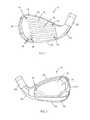
- FIG. 1is a front perspective view of a golf club head in accordance with the present invention
- FIG. 2is a rear perspective view of the golf club head of FIG. 1 ;
- FIG. 3is an exploded view of the golf club head of FIG. 1 ;
- FIG. 4is a rear view of another embodiment of a golf club head in accordance with the present invention.
- FIG. 5is a rear view of an embodiment of a sole member included in a golf club head of the present invention.
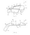
- FIG. 6is a rear view of another embodiment of a golf club head in accordance with the present invention.
- FIG. 7is a rear view of a portion of the golf club head of FIG. 6 ;
- FIG. 8is a side view of a sole member of the golf club head of FIG. 6 .
- FIG. 9is another side view of the sole member of FIG. 8 ;
- FIG. 10is an alternative embodiment of a sole member that may be included in the golf club head of FIG. 6 ;
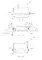
- FIG. 11is a rear perspective view of another embodiment of a golf club head in accordance with the present invention.
- FIG. 12is a side view of a portion of the golf club head of FIG. 11 ;
- FIG. 13is a side view of a sole member of the golf club head of FIG. 11 ;
- FIG. 14is another side view of the sole member of FIG. 13 ;
- FIG. 15is another side view of the sole member of FIG. 13 .
- the present inventionis directed to modular golf clubs.
- the inventive golf clubsgenerally include a multi-component structure that allows various attributes to be altered.
- an iron-type golf club head 10generally includes a face 12 and a body 16 that supports face 12 .
- Face 12includes a generally planar ball striking surface 14 and a plurality of score lines 18 , or grooves, that extend into face 12 from ball striking surface 14 .
- Score lines 18assist in imparting spin to a golf ball during impact and may have various configurations to produce desired spin characteristics.
- Body 16provides the majority of the mass of club head 10 and is configured to distribute the mass so that club head has a desired behavior during impact with a golf ball and/or the ground during a swing.
- body 16may have a muscle-back or a cavity-back configuration so that the forgiveness and playability may be tuned.
- body 16has a cavity-back configuration that provides perimeter weighting to increase the moment of inertia of club head 10 to add forgiveness during misaligned ball impacts.
- the mass of body 16is concentrated in locations spaced from the geometric center of club head 10 , such as in a heel portion 20 and a toe portion 22 .
- Body 16also includes a hosel 28 for attaching a golf club shaft.
- a back platemay also be attached to body 16 .
- the back platemay be coupled to any portion of body 16 , such as within a back cavity 32 that is defined by the perimeter weighting of body 16 and a rear surface 15 of face 12 .
- the back platemay be constructed to provide weight adjustment, vibration damping and/or desired aesthetics as will be described in greater detail below. [multi-material, etc]
- Sole portion 24 of golf club head 10may also include a sole member 36 that is constructed separate from body 16 and coupled thereto.
- body 16includes a sole cavity 34 that is configured to receive a sole member 36 .
- Sole member 36is shaped to complement the shape of sole cavity 34 .
- sole member 36includes a heel portion 46 and a toe portion 47 that are each generally more voluminous than a necked down central portion 48 .
- the shapeis generally preferred so that the moment of inertia may be altered more efficiently by altering the mass properties of the sole member such as by including weight inserts or cavities in selected portions of the sole member 36 .
- sole member 36is removably coupled to body 16 using removable mechanical fasteners 44 that extend through body 16 .
- the removable fastenerscouple both sole member 36 and face 12 to body 16 so that body 16 is sandwiched therebetween.
- a plurality of aperturesis included in face 12 and the apertures preferably receive threaded fasteners that extend into body 16 .
- upper apertures 38extend through face 12 and align with threaded bores included in body 16 .
- Lower apertures 40extend through face 12 and align with apertures 42 of body 16 and threaded bores included in sole member 36 .
- Face 12 , body 16 and sole member 36may be constructed from any metal or non-metal material. Suitable materials for the components include metallic materials such as aluminum, stainless steel, carbon steel, titanium, magnesium, and alloys thereof; and non-metallic materials such as carbon fiber composites, plastics and fiber reinforced plastics. Additionally, face 12 may be constructed so that it may be disposable such as by having a selected wear rate that requires the face to be replaced after a predetermined amount of use. Suitable materials for body 16 include, but are not limited to, stainless steel, carbon steel, titanium, aluminum and alloys thereof and portions may be constructed from materials having greater density such as lead, tungsten, gold, or silver to provide a desired mass distribution.
- a golf club head 40includes an alternative configuration of the fastening features for a face 52 , a body 56 and a sole member 58 .
- the fastening featuresare oriented so that they are not visible on the ball striking surface of the golf club head.
- body 56includes a plurality of apertures 60 located generally around a back cavity 62 of the golf club head that are configured to receive fasteners 61 .
- Sole member 58also includes apertures 64 that are aligned with corresponding apertures in body 56 and are configured to receive fasteners 61 .
- Face 52includes a plurality of threaded bores that are engaged by the fasteners to retain face 52 and sole member 58 coupled to body 56 .
- a plurality of sole members and facesmay be provided and removably coupled to the body so that a plurality of configurations of the golf club head may be created.
- Combinations of a face and a sole membermay be provided so that the overall mass of the golf club head may be held constant while the mass is shifted to different portions of the golf club head.
- a combination having a lightweight face and a heavy sole membermay be provided in addition to a combination having a heavy face and a lightweight sole member while each combination has the same overall mass.
- a plurality of sole membersmay be provided having different masses and/or weight ports or cavities so that mass may be added or removed from the golf club head.
- a plurality of sole membersmay be provided having different shapes including bounce surfaces, heel/toe relief, and camber.
- sole member 66provides an alternative bounce surface that includes a plurality of rails 67 separated by a central depression 68 .
- the rails 67converge from the trailing edge to a front edge of the sole member. Rails 67 are positioned so that they are approximately equidistant from the heel to toe center of the sole of the golf club head.
- Each rail 67defines a ground contact surface 69 that is offset relative to the remainder of the sole member so that when sole member 66 is installed in a golf club and the golf club is placed at address, the ground contact surfaces define the lowest portions of the golf club.
- the sole membermay include a single rail that may further be located centrally on the sole member.
- the railsneed not be convergent toward the leading edge, and may alternatively be divergent in that direction or parallel in a forward/aft direction.
- the sole membermay only include one or more depressions so that portions of the lower sole surface are offset toward a top line portion of the club head relative to the remainder of the lower sole surface.
- a plurality of different facesmay be provided that include a plurality of different configurations.
- the configurationsmay alter any attribute of the face and/or the club head, such as spin generation and mass distribution.
- the plurality of different facesmay have different masses, hardness, groove configurations, materials, machine patterns, roughness, coatings and/or surface treatments.
- a plurality of bodiesmay be provided.
- the plurality of bodiesprovide alternative configurations for various physical attributes. Those physical attributes include the amount of offset, loft, lie, bounce, sole width/shape, mass distribution, hosel length, topline thickness, etc.
- golf club head 70has a muscle-back configuration and includes a body 72 , a sole member 74 and a fastener 76 .
- Fastener 76extends through an aperture included in body 72 and engages a bore 78 included in sole member 74 so that sole member 74 is releasably coupled to body 72 .
- the mass of body 72is generally distributed more evenly horizontally across the club head from a heel portion 80 to a toe portion 82 compared to the previously described cavity-back configuration. However, the mass of body 72 is concentrated vertically below the geometric center in a muscle portion of the club head that includes a sole portion 84 . Above the muscle portion, in the upper portion of the golf club head, the mass of body 72 is evenly distributed to a top line portion 86 . Body 72 also includes a hosel 88 for attaching a golf club shaft.
- the muscle portion of the golf club headis configured to receive and to be removably coupled to sole member 74 .
- a portion of the muscle back portionis configured to provide a receptacle for sole member 74 .
- the receptacleis generally defined by a heel side wall 98 , a toe side wall 100 , a top wall 99 and a base wall 101 and is formed as a tapered slot 90 that is tapered so that it narrows toward top wall 99 and fastener 76 .
- Slot 90also includes a peripheral undercut formed by a plurality of undercuts 104 , 105 , 106 .
- the undercutsare aligned in a plane that is parallel to a ball-striking face of golf club 70 .
- Sole member 74is shaped to complement the shape of the receptacle, slot 90 .
- sole member 74is generally wedge-shaped and includes side walls that generally converge from a leading edge 96 to a trailing edge 94 .
- slot 90 and sole member 74are shaped so that as fastener 76 is tightened, sole member 74 is drawn into forcible abutment with a heel side wall 98 and a toe side wall 100 of slot 90 .
- a plurality of flangesincluding heel flange 107 , toe flange 108 , and top flange 109 are included on sole member 74 that slidably engage the peripheral undercuts of slot 90 .
- the undercuts of slot 90 and the flanges of sole member 74are oriented so that sole member 74 is slidably received in slot 90 in a direction from the leading edge to the top line and parallel to the ball-striking face so that base wall 101 of slot 90 slides against a base wall 95 of sole member 74 .
- the undercuts and flangesmay be provided around any portion of the perimeters of the slot and the sole member. As shown, those features are located on the heel side, the toe side and the top side of the slot and sole member, but it should be appreciated that they may be included on only the heel and/or toe sides or only on the top side if desired.
- the interface between sole member 74 and slot 90is selected to minimize the forces placed on fastener 76 during use of the golf club.
- the interfaceis configured so that during impact between the golf club and the playing surface and between the golf club and a golf ball the forces are predominantly transferred directly between body 72 and sole member 74 , rather than through fastener 76 .
- the engagement of the undercuts and flangesprovide a direct load path between the sole member and the body.
- the sole membermay be constructed as a single, homogeneous component or it may have a multi-piece and/or multi-material construction.
- a sole member 110includes a multi-piece and multi-material construction.
- sole member 110includes a body member 112 and an insert 114 .
- Sole member 110is shaped to complement the shape of slot 90 of body 72 .
- sole member 110is generally wedge-shaped and has an overall fore to aft width that generally decreases from a trailing edge 116 to a leading edge 118 and an overall heel to toe length that generally increases from trailing edge 116 to leading edge 118 .
- slot 90 and sole member 110are shaped so that as fastener 76 is tightened in bore 120 , sole member 110 is drawn into forcible abutment with a heel side surface 98 and a toe side surface 100 of slot 90 .
- a golf club head 130has a muscle-back configuration and includes a body 132 having a ball striking surface 133 , an insert (e.g., sole member 134 ) and a plurality of fasteners 136 .
- Each of fasteners 136extends through an aperture included in body 132 and engages a bore included in sole member 134 so that sole member 134 is releasably coupled to body 132 .
- the mass of body 132is generally distributed more evenly horizontally across the club head from a heel portion 138 to a toe portion 140 compared to the previously described cavity-back configuration. However, the mass of body 132 is concentrated vertically below the geometric center in a muscle portion of the club head that includes a sole portion 134 . Above the muscle portion, in the upper portion of the golf club head, the mass of body 132 is evenly distributed to a top line portion 142 . Body 132 also includes a hosel 144 for attaching a golf club shaft.
- the muscle portion of the golf club headis configured to receive and to be coupled to sole member 134 .
- a portion of the muscle back portionis removed to provide a receptacle for sole member 134 .
- the receptacleis formed as a channel 146 that extends through the muscle back portion and a portion of the upper portion of the golf club toward top line portion 142 .
- Channel 146is formed by a base wall 148 , a heel side wall 150 and a toe side wall 152 .
- Base wallis a substantially planar wall that is approximately parallel with ball striking surface 133 .
- Heel side wall 150 and toe side wall 152are each angled relative to base wall 148 so that channel is wider in a heel to toe direction at a trailing edge 154 of the golf club head than adjacent a leading edge 156 so that they each define a draft angle ⁇ , shown in FIG. 12 .
- Sole member 134is received within channel 146 and is coupled to body 132 using fasteners 136 .
- Sole member 134includes a base wall 158 , a heel side wall 160 , a toe side wall 162 , a sole wall 164 , and an aft wall 166 .
- Base wall 158forms a generally curved or planar surface that abuts base wall 148 of channel 146 when sole member 134 is engaged with body 132 .
- Each of heel side wall 160 and toe side wall 162is angled relative to base wall 158 by an angle ⁇ .
- angle 0has a magnitude that is less than the magnitude of angle a so that there is an angled gap 168 having an angle ⁇ , corresponding to the difference between angles ⁇ and ⁇ , between the adjacent side walls of sole member 134 and channel 146 .
- Fasteners 136are oriented in a heel to toe direction so that tightening fasteners 136 reduces the size of gap 168 and places the ball-striking surface 133 in tension.
- the wallis preferably cylindrical. In the present embodiment, tension is applied across the face in a heel to toe direction, but it should be appreciated that the receptacle and the insert may be oriented to provide any desired tension orientation.
- the insertmay include features to alter the mass of the insert while providing an outer profile that matches the remainder of the golf club head body.
- sole member 134includes a weight insert 170 that increases the mass of sole member 134 so that golf club head 130 has a desired overall mass. It should be appreciated that any mass altering features may be included, such as weights and cavities so that the mass of the insert may be increased or reduced.
- the apertures included in body 132 that receive fasteners 136extend generally in a heel to toe direction and intersect channel 146 .
Landscapes
- Health & Medical Sciences (AREA)
- General Health & Medical Sciences (AREA)
- Physical Education & Sports Medicine (AREA)
- Golf Clubs (AREA)
Abstract
Description
Claims (12)
Priority Applications (2)
| Application Number | Priority Date | Filing Date | Title |
|---|---|---|---|
| US12/760,684US8491405B2 (en) | 2010-04-15 | 2010-04-15 | Modular golf club |
| US13/946,399US8840485B2 (en) | 2010-04-15 | 2013-07-19 | Modular golf club |
Applications Claiming Priority (1)
| Application Number | Priority Date | Filing Date | Title |
|---|---|---|---|
| US12/760,684US8491405B2 (en) | 2010-04-15 | 2010-04-15 | Modular golf club |
Related Child Applications (1)
| Application Number | Title | Priority Date | Filing Date |
|---|---|---|---|
| US13/946,399ContinuationUS8840485B2 (en) | 2010-04-15 | 2013-07-19 | Modular golf club |
Publications (2)
| Publication Number | Publication Date |
|---|---|
| US20110256953A1 US20110256953A1 (en) | 2011-10-20 |
| US8491405B2true US8491405B2 (en) | 2013-07-23 |
Family
ID=44788599
Family Applications (2)
| Application Number | Title | Priority Date | Filing Date |
|---|---|---|---|
| US12/760,684Active2031-10-11US8491405B2 (en) | 2010-04-15 | 2010-04-15 | Modular golf club |
| US13/946,399ActiveUS8840485B2 (en) | 2010-04-15 | 2013-07-19 | Modular golf club |
Family Applications After (1)
| Application Number | Title | Priority Date | Filing Date |
|---|---|---|---|
| US13/946,399ActiveUS8840485B2 (en) | 2010-04-15 | 2013-07-19 | Modular golf club |
Country Status (1)
| Country | Link |
|---|---|
| US (2) | US8491405B2 (en) |
Cited By (19)
| Publication number | Priority date | Publication date | Assignee | Title |
|---|---|---|---|---|
| US20130109497A1 (en)* | 2011-10-27 | 2013-05-02 | Bridgestone Sports Co., Ltd. | Golf club head |
| US20130165251A1 (en)* | 2011-12-27 | 2013-06-27 | Douglas C. Jorgensen | Golf club with reversible sole |
| US20130344988A1 (en)* | 2012-06-20 | 2013-12-26 | Ronald K. Hettinger | Iron-type golf club |
| US20140274441A1 (en)* | 2013-03-13 | 2014-09-18 | Karsten Manufacturing Corporation | Variable bounce height club heads and related methods |
| US8840485B2 (en)* | 2010-04-15 | 2014-09-23 | Acushnet Company | Modular golf club |
| US20160193511A1 (en)* | 2013-03-13 | 2016-07-07 | Karsten Manufacturing Corporation | Variable bounce height club heads and related methods |
| US9579548B2 (en) | 2012-05-31 | 2017-02-28 | Nike, Inc. | Golf club head or other ball striking device with face having modulus variance |
| US20170252613A1 (en)* | 2016-03-01 | 2017-09-07 | Nike, Inc | Iron-type golf club head or other ball striking device |
| US9821202B2 (en) | 2009-05-29 | 2017-11-21 | Acushnet Company | Wedge type golf club head |
| US20180256946A1 (en)* | 2007-07-25 | 2018-09-13 | Karsten Manufacturing Corporation | Club head sets with varying characteristics and related methods |
| US20180280768A1 (en)* | 2011-11-28 | 2018-10-04 | Acushnet Company | Golf club head and method of manufacture |
| US10137339B1 (en) | 2017-12-29 | 2018-11-27 | Acushnet Company | Golf club having removable face |
| US10166444B1 (en) | 2017-12-29 | 2019-01-01 | Acushnet Company | Golf club with removable face |
| US10384105B2 (en)* | 2017-12-28 | 2019-08-20 | Acushnet Company | Golf club with interchangeable sole |
| US10661128B2 (en) | 2015-10-06 | 2020-05-26 | Sumitomo Rubber Industries, Ltd. | Adjustable club head |
| US10780329B2 (en) | 2015-10-06 | 2020-09-22 | Sumitomo Rubber Industries, Ltd. | Multi-component golf club wedge |
| US11065513B2 (en) | 2011-11-28 | 2021-07-20 | Acushnet Company | Set of golf club heads and method of manufacture |
| US20230070096A1 (en)* | 2021-09-09 | 2023-03-09 | Acushnet Company | Golf club head with improved striking face |
| US12296235B2 (en) | 2023-04-28 | 2025-05-13 | Acushnet Company | Modular golf club including an interchangeable sole |
Families Citing this family (11)
| Publication number | Priority date | Publication date | Assignee | Title |
|---|---|---|---|---|
| US10434389B2 (en)* | 2009-06-11 | 2019-10-08 | Karsten Manufacturing Corporation | Golf club weight attachment mechanisms and related methods |
| US11918867B2 (en) | 2011-11-28 | 2024-03-05 | Acushnet Company | Co-forged golf club head and method of manufacture |
| US20160184669A1 (en)* | 2011-11-28 | 2016-06-30 | Acushnet Company | Co-forged golf club head and method of manufacture |
| US20130288823A1 (en) | 2011-11-28 | 2013-10-31 | Acushnet Company | Co-forged golf club head and method of manufacture |
| US8911302B1 (en) | 2012-10-29 | 2014-12-16 | Callaway Golf Company | Iron-type golf club head |
| JP5572249B1 (en)* | 2013-07-30 | 2014-08-13 | ダンロップスポーツ株式会社 | Iron type golf club head |
| US9750993B2 (en)* | 2015-02-19 | 2017-09-05 | Acushnet Company | Weighted iron set |
| KR102607133B1 (en)* | 2015-05-22 | 2023-11-27 | 카스턴 매뉴팩츄어링 코오포레이숀 | Golf club head with high-density body and low-density face |
| JP6711175B2 (en)* | 2016-06-30 | 2020-06-17 | 住友ゴム工業株式会社 | Iron type golf club head |
| CN108905114A (en)* | 2018-08-27 | 2018-11-30 | 南京佑天金属科技有限公司 | A kind of glof club head |
| JP7725898B2 (en)* | 2021-07-12 | 2025-08-20 | 住友ゴム工業株式会社 | Golf club head |
Citations (35)
| Publication number | Priority date | Publication date | Assignee | Title |
|---|---|---|---|---|
| US2328583A (en) | 1941-05-17 | 1943-09-07 | Milton B Reach | Golf club |
| US2332342A (en) | 1940-03-08 | 1943-10-19 | Milton B Reach | Golf club |
| US2530446A (en) | 1947-05-08 | 1950-11-21 | John A Beardsley | Combination golf club |
| US2774600A (en) | 1954-02-25 | 1956-12-18 | Milton B Reach | Anti-nicking golf club |
| US4540178A (en)* | 1983-08-30 | 1985-09-10 | Johnson Louis W | Golf iron and method of construction |
| US4630827A (en) | 1984-03-19 | 1986-12-23 | Yonex Kabushiki Kaisha | Golf club head |
| US4667963A (en)* | 1985-03-18 | 1987-05-26 | Yonex Kabushiki Kaisha | Golf club head |
| US4699383A (en) | 1985-03-28 | 1987-10-13 | Maruman Golf Co., Ltd. | Club-head |
| US4883275A (en)* | 1986-07-21 | 1989-11-28 | Lynx Golf, Inc. | Gold club iron head |
| US4992236A (en) | 1990-01-16 | 1991-02-12 | Shira Chester S | Method of making a golf club head and the article produced thereby |
| US5050879A (en) | 1990-01-22 | 1991-09-24 | Cipa Manufacturing Corporation | Golf driver with variable weighting for changing center of gravity |
| US5190290A (en)* | 1990-11-13 | 1993-03-02 | Daiwa Golf Co., Ltd. | Head for golf club |
| US5275413A (en) | 1992-12-17 | 1994-01-04 | Tom Sprague | Golf club with supplement portion |
| US5346213A (en) | 1992-01-23 | 1994-09-13 | Daiwa Golf Co., Ltd. | Golf club head |
| US5439223A (en) | 1992-04-02 | 1995-08-08 | Kobayashi; Kenji | Golf club head |
| US5509660A (en) | 1993-08-17 | 1996-04-23 | Elmer; John C. | Golf clubs |
| US5522593A (en)* | 1993-05-31 | 1996-06-04 | Kabushiki Kaisha Endo Seisakusho | Golf club head |
| US5536011A (en)* | 1994-06-21 | 1996-07-16 | Gutowski; Thaddeus | Perimeter-weighted golf club iron and method for making same |
| US5540436A (en)* | 1994-10-25 | 1996-07-30 | Lynx Golf, Inc. | Set of golf club irons having a low density rear cavity perimeter insert for selected weight distribution of each iron |
| US5776010A (en)* | 1997-01-22 | 1998-07-07 | Callaway Golf Company | Weight structure on a golf club head |
| US5807186A (en) | 1997-03-18 | 1998-09-15 | Chen; Archer C. C. | Golf club including lie adjusting device |
| US5833551A (en)* | 1996-09-09 | 1998-11-10 | Taylor Made Golf Company, Inc. | Iron golf club head |
| US5938540A (en) | 1998-01-27 | 1999-08-17 | Lu; Clive S. | Golf club with interchangeable sole |
| US6080068A (en) | 1997-12-26 | 2000-06-27 | Kabushiki Kaisha Endo Seisakusho | Golf club |
| US6290609B1 (en)* | 1999-03-11 | 2001-09-18 | K.K. Endo Seisakusho | Iron golf club |
| US6554719B2 (en)* | 1998-02-09 | 2003-04-29 | Taylor Made Golf Company, Inc. | Correlated set of golf clubs |
| US6569029B1 (en) | 2001-08-23 | 2003-05-27 | Edward Hamburger | Golf club head having replaceable bounce angle portions |
| US6592468B2 (en)* | 2000-12-01 | 2003-07-15 | Taylor Made Golf Company, Inc. | Golf club head |
| US6929563B2 (en)* | 2002-06-20 | 2005-08-16 | Bridgestone Sports Co., Ltd. | Iron type golf club head |
| US7022027B2 (en)* | 2003-09-05 | 2006-04-04 | Chen Ming T | Tri-weight correlated set of iron type golf clubs |
| US7144336B2 (en)* | 2002-09-20 | 2006-12-05 | Callaway Golf Company | Iron golf club |
| US7530902B2 (en)* | 2006-06-12 | 2009-05-12 | Sri Sports Limited | Iron-type golf club head |
| US7604550B1 (en) | 2006-12-12 | 2009-10-20 | Marvin Kirk Currie | Sand wedge with an interchangeable faceplate |
| US7749100B2 (en)* | 2006-07-11 | 2010-07-06 | Nike, Inc. | Golf clubs and golf club heads having fluid-filled bladders and/or interior chambers |
| US7988565B2 (en)* | 2008-07-31 | 2011-08-02 | Sri Sports Limited | Golf club head |
Family Cites Families (21)
| Publication number | Priority date | Publication date | Assignee | Title |
|---|---|---|---|---|
| US1349805A (en)* | 1919-03-27 | 1920-08-17 | Charles W Booth | Golf-club |
| US1355889A (en)* | 1920-02-11 | 1920-10-19 | Alfred J Campbell | Golf-club |
| US1509429A (en)* | 1924-01-19 | 1924-09-23 | John A Hillerich | Golf club |
| US1525352A (en)* | 1924-02-27 | 1925-02-03 | Aitken James Abram Garfield | Golf-club |
| US1535270A (en)* | 1924-11-01 | 1925-04-28 | Ralph G Tyler | Golf club |
| US3692306A (en)* | 1971-02-18 | 1972-09-19 | Cecil C Glover | Golf club having integrally formed face and sole plate with weight means |
| USD307783S (en)* | 1986-08-01 | 1990-05-08 | Daiwa Gold Co., Ltd. | Golf club head |
| CA2415721A1 (en)* | 2000-07-13 | 2002-01-24 | Spalding Sports Worldwide, Inc. | Iron type golf club head with high strength insert |
| US8182362B2 (en)* | 2001-12-17 | 2012-05-22 | Fu Sheng Industrial Co., Ltd. | Golf club head |
| JP2007260316A (en) | 2006-03-30 | 2007-10-11 | Daiwa Seiko Inc | Iron golf club |
| US7662051B2 (en)* | 2007-09-11 | 2010-02-16 | Cindy Rhodes | Golf head |
| US8062150B2 (en)* | 2007-09-13 | 2011-11-22 | Acushnet Company | Iron-type golf club |
| US20090082133A1 (en)* | 2007-09-20 | 2009-03-26 | Nelson Precision Casting Co., Ltd. | Plating layer structure of golf club head and forming method thereof |
| JP4378736B2 (en) | 2007-10-16 | 2009-12-09 | 福寿 佐藤 | Golf club |
| US20090291772A1 (en)* | 2008-05-21 | 2009-11-26 | Robert Boyd | Golf club and golf club head with interchangeable body component |
| JP5406467B2 (en)* | 2008-06-06 | 2014-02-05 | ダンロップスポーツ株式会社 | Iron type golf club head |
| US7651413B1 (en)* | 2008-07-09 | 2010-01-26 | Well Jet International Co., Ltd. | Golf club head of heterogeneous metals |
| JP4977176B2 (en)* | 2009-06-23 | 2012-07-18 | ダンロップスポーツ株式会社 | Iron type golf club head |
| US8491405B2 (en)* | 2010-04-15 | 2013-07-23 | Acushnet Company | Modular golf club |
| US8454453B2 (en)* | 2011-03-09 | 2013-06-04 | Acushnet Company | Multi-material iron type golf club head |
| JP5872847B2 (en)* | 2011-10-27 | 2016-03-01 | ブリヂストンスポーツ株式会社 | Golf club head |
- 2010
- 2010-04-15USUS12/760,684patent/US8491405B2/enactiveActive
- 2013
- 2013-07-19USUS13/946,399patent/US8840485B2/enactiveActive
Patent Citations (35)
| Publication number | Priority date | Publication date | Assignee | Title |
|---|---|---|---|---|
| US2332342A (en) | 1940-03-08 | 1943-10-19 | Milton B Reach | Golf club |
| US2328583A (en) | 1941-05-17 | 1943-09-07 | Milton B Reach | Golf club |
| US2530446A (en) | 1947-05-08 | 1950-11-21 | John A Beardsley | Combination golf club |
| US2774600A (en) | 1954-02-25 | 1956-12-18 | Milton B Reach | Anti-nicking golf club |
| US4540178A (en)* | 1983-08-30 | 1985-09-10 | Johnson Louis W | Golf iron and method of construction |
| US4630827A (en) | 1984-03-19 | 1986-12-23 | Yonex Kabushiki Kaisha | Golf club head |
| US4667963A (en)* | 1985-03-18 | 1987-05-26 | Yonex Kabushiki Kaisha | Golf club head |
| US4699383A (en) | 1985-03-28 | 1987-10-13 | Maruman Golf Co., Ltd. | Club-head |
| US4883275A (en)* | 1986-07-21 | 1989-11-28 | Lynx Golf, Inc. | Gold club iron head |
| US4992236A (en) | 1990-01-16 | 1991-02-12 | Shira Chester S | Method of making a golf club head and the article produced thereby |
| US5050879A (en) | 1990-01-22 | 1991-09-24 | Cipa Manufacturing Corporation | Golf driver with variable weighting for changing center of gravity |
| US5190290A (en)* | 1990-11-13 | 1993-03-02 | Daiwa Golf Co., Ltd. | Head for golf club |
| US5346213A (en) | 1992-01-23 | 1994-09-13 | Daiwa Golf Co., Ltd. | Golf club head |
| US5439223A (en) | 1992-04-02 | 1995-08-08 | Kobayashi; Kenji | Golf club head |
| US5275413A (en) | 1992-12-17 | 1994-01-04 | Tom Sprague | Golf club with supplement portion |
| US5522593A (en)* | 1993-05-31 | 1996-06-04 | Kabushiki Kaisha Endo Seisakusho | Golf club head |
| US5509660A (en) | 1993-08-17 | 1996-04-23 | Elmer; John C. | Golf clubs |
| US5536011A (en)* | 1994-06-21 | 1996-07-16 | Gutowski; Thaddeus | Perimeter-weighted golf club iron and method for making same |
| US5540436A (en)* | 1994-10-25 | 1996-07-30 | Lynx Golf, Inc. | Set of golf club irons having a low density rear cavity perimeter insert for selected weight distribution of each iron |
| US5833551A (en)* | 1996-09-09 | 1998-11-10 | Taylor Made Golf Company, Inc. | Iron golf club head |
| US5776010A (en)* | 1997-01-22 | 1998-07-07 | Callaway Golf Company | Weight structure on a golf club head |
| US5807186A (en) | 1997-03-18 | 1998-09-15 | Chen; Archer C. C. | Golf club including lie adjusting device |
| US6080068A (en) | 1997-12-26 | 2000-06-27 | Kabushiki Kaisha Endo Seisakusho | Golf club |
| US5938540A (en) | 1998-01-27 | 1999-08-17 | Lu; Clive S. | Golf club with interchangeable sole |
| US6554719B2 (en)* | 1998-02-09 | 2003-04-29 | Taylor Made Golf Company, Inc. | Correlated set of golf clubs |
| US6290609B1 (en)* | 1999-03-11 | 2001-09-18 | K.K. Endo Seisakusho | Iron golf club |
| US6592468B2 (en)* | 2000-12-01 | 2003-07-15 | Taylor Made Golf Company, Inc. | Golf club head |
| US6569029B1 (en) | 2001-08-23 | 2003-05-27 | Edward Hamburger | Golf club head having replaceable bounce angle portions |
| US6929563B2 (en)* | 2002-06-20 | 2005-08-16 | Bridgestone Sports Co., Ltd. | Iron type golf club head |
| US7144336B2 (en)* | 2002-09-20 | 2006-12-05 | Callaway Golf Company | Iron golf club |
| US7022027B2 (en)* | 2003-09-05 | 2006-04-04 | Chen Ming T | Tri-weight correlated set of iron type golf clubs |
| US7530902B2 (en)* | 2006-06-12 | 2009-05-12 | Sri Sports Limited | Iron-type golf club head |
| US7749100B2 (en)* | 2006-07-11 | 2010-07-06 | Nike, Inc. | Golf clubs and golf club heads having fluid-filled bladders and/or interior chambers |
| US7604550B1 (en) | 2006-12-12 | 2009-10-20 | Marvin Kirk Currie | Sand wedge with an interchangeable faceplate |
| US7988565B2 (en)* | 2008-07-31 | 2011-08-02 | Sri Sports Limited | Golf club head |
Cited By (35)
| Publication number | Priority date | Publication date | Assignee | Title |
|---|---|---|---|---|
| US11465018B2 (en)* | 2007-07-25 | 2022-10-11 | Karsten Manufacturing Corporation | Club head sets with varying characteristics and related methods |
| US20180256946A1 (en)* | 2007-07-25 | 2018-09-13 | Karsten Manufacturing Corporation | Club head sets with varying characteristics and related methods |
| US9821202B2 (en) | 2009-05-29 | 2017-11-21 | Acushnet Company | Wedge type golf club head |
| US8840485B2 (en)* | 2010-04-15 | 2014-09-23 | Acushnet Company | Modular golf club |
| US20130109497A1 (en)* | 2011-10-27 | 2013-05-02 | Bridgestone Sports Co., Ltd. | Golf club head |
| US8876624B2 (en)* | 2011-10-27 | 2014-11-04 | Bridgestone Sports Co., Ltd. | Golf club head |
| US12121783B2 (en) | 2011-11-28 | 2024-10-22 | Acushnet Company | Set of golf club heads and method of manufacture |
| US11065513B2 (en) | 2011-11-28 | 2021-07-20 | Acushnet Company | Set of golf club heads and method of manufacture |
| US20180280768A1 (en)* | 2011-11-28 | 2018-10-04 | Acushnet Company | Golf club head and method of manufacture |
| US11504589B2 (en) | 2011-11-28 | 2022-11-22 | Acushnet Company | Set of golf club heads and method of manufacture |
| US20130165251A1 (en)* | 2011-12-27 | 2013-06-27 | Douglas C. Jorgensen | Golf club with reversible sole |
| US10080935B2 (en) | 2012-05-31 | 2018-09-25 | Karsten Manufacturing Corporation | Golf club head or other ball striking device with face having modulus variance |
| US9579548B2 (en) | 2012-05-31 | 2017-02-28 | Nike, Inc. | Golf club head or other ball striking device with face having modulus variance |
| US10427013B2 (en) | 2012-05-31 | 2019-10-01 | Karsten Manufacturing Corporation | Golf club head or other ball striking device with face having modulus variance |
| US11358036B2 (en) | 2012-05-31 | 2022-06-14 | Karsten Manufacturing Corporation | Golf club head or other ball striking device with face having modulus variance |
| US20130344988A1 (en)* | 2012-06-20 | 2013-12-26 | Ronald K. Hettinger | Iron-type golf club |
| US20140274441A1 (en)* | 2013-03-13 | 2014-09-18 | Karsten Manufacturing Corporation | Variable bounce height club heads and related methods |
| US10974108B2 (en)* | 2013-03-13 | 2021-04-13 | Karsten Manufacturing Corporation | Variable bounce height club heads and related methods |
| US10137341B2 (en)* | 2013-03-13 | 2018-11-27 | Karsten Manufacturing Corporation | Variable bounce height club heads and related methods |
| US20160193511A1 (en)* | 2013-03-13 | 2016-07-07 | Karsten Manufacturing Corporation | Variable bounce height club heads and related methods |
| US10525313B2 (en)* | 2013-03-13 | 2020-01-07 | Karsten Manufacturing Corporation | Variable bounce height club heads and related methods |
| US10661128B2 (en) | 2015-10-06 | 2020-05-26 | Sumitomo Rubber Industries, Ltd. | Adjustable club head |
| US10780329B2 (en) | 2015-10-06 | 2020-09-22 | Sumitomo Rubber Industries, Ltd. | Multi-component golf club wedge |
| US10300352B2 (en)* | 2016-03-01 | 2019-05-28 | Karsten Manufacturing Corporation | Iron-type golf club head or other ball striking device |
| US10881922B2 (en) | 2016-03-01 | 2021-01-05 | Karsten Manufacturing Corporation | Iron-type golf club head or other ball striking device |
| US11819742B2 (en) | 2016-03-01 | 2023-11-21 | Karsten Manufacturing Corporation | Iron-type golf club head or other ball striking device |
| US20170252613A1 (en)* | 2016-03-01 | 2017-09-07 | Nike, Inc | Iron-type golf club head or other ball striking device |
| US10806980B2 (en)* | 2017-12-28 | 2020-10-20 | Acushnet Company | Golf club with interchangeable sole |
| US20190366175A1 (en)* | 2017-12-28 | 2019-12-05 | Acushnet Company | Golf club with interchangeable sole |
| US10384105B2 (en)* | 2017-12-28 | 2019-08-20 | Acushnet Company | Golf club with interchangeable sole |
| US10166444B1 (en) | 2017-12-29 | 2019-01-01 | Acushnet Company | Golf club with removable face |
| US10137339B1 (en) | 2017-12-29 | 2018-11-27 | Acushnet Company | Golf club having removable face |
| US20230070096A1 (en)* | 2021-09-09 | 2023-03-09 | Acushnet Company | Golf club head with improved striking face |
| US11969630B2 (en)* | 2021-09-09 | 2024-04-30 | Acushnet Company | Golf club head with improved striking face |
| US12296235B2 (en) | 2023-04-28 | 2025-05-13 | Acushnet Company | Modular golf club including an interchangeable sole |
Also Published As
| Publication number | Publication date |
|---|---|
| US8840485B2 (en) | 2014-09-23 |
| US20130303302A1 (en) | 2013-11-14 |
| US20110256953A1 (en) | 2011-10-20 |
Similar Documents
| Publication | Publication Date | Title |
|---|---|---|
| US8491405B2 (en) | Modular golf club | |
| US10245484B2 (en) | Iron type golf club head | |
| US8414422B2 (en) | External weight for golf club head | |
| US8449408B2 (en) | Iron-type golf clubs | |
| US10258849B2 (en) | Golf club and golf club head structures | |
| US10245480B2 (en) | Golf club head or other ball striking device having impact-influencing body features | |
| US8376878B2 (en) | Golf club head having variable center of gravity location | |
| US11684834B2 (en) | Iron-type golf club heads with a dual-density insert | |
| US8262506B2 (en) | Golf club head with composite weight port | |
| US8550933B2 (en) | Swing-weight-adjustable golf clubs and clubheads | |
| US7083531B2 (en) | Iron-type golf club | |
| US7238119B2 (en) | Golf club head with undercut | |
| US8608591B2 (en) | Golf club head | |
| US7942760B2 (en) | Transitioning hollow golf clubs | |
| US12121779B1 (en) | Systems and methods for a weighted golf club head | |
| US11617925B2 (en) | Golf club heads and methods to manufacture golf club heads | |
| US20130165251A1 (en) | Golf club with reversible sole | |
| US10166444B1 (en) | Golf club with removable face | |
| US10137339B1 (en) | Golf club having removable face | |
| US20240058658A1 (en) | Golf club heads and methods to manufacture golf club heads | |
| US20230302331A1 (en) | Weighted iron set | |
| US20240149120A1 (en) | Golf club head |
Legal Events
| Date | Code | Title | Description |
|---|---|---|---|
| AS | Assignment | Owner name:ACUSHNET COMPANY, MASSACHUSETTS Free format text:ASSIGNMENT OF ASSIGNORS INTEREST;ASSIGNORS:JORGENSEN, DOUGLAS C.;RICK, HELENE;ROACH, RYAN L.;AND OTHERS;SIGNING DATES FROM 20100413 TO 20100414;REEL/FRAME:024236/0618 | |
| AS | Assignment | Owner name:KOREA DEVELOPMENT BANK, NEW YORK BRANCH, NEW YORK Free format text:SECURITY AGREEMENT;ASSIGNOR:ACUSHNET COMPANY;REEL/FRAME:027347/0053 Effective date:20111031 | |
| STCF | Information on status: patent grant | Free format text:PATENTED CASE | |
| AS | Assignment | Owner name:WELLS FARGO BANK, NATIONAL ASSOCIATION, AS ADMINISTRATIVE AGENT, CALIFORNIA Free format text:SECURITY INTEREST;ASSIGNOR:ACUSHNET COMPANY;REEL/FRAME:039506/0030 Effective date:20160728 Owner name:WELLS FARGO BANK, NATIONAL ASSOCIATION, AS ADMINIS Free format text:SECURITY INTEREST;ASSIGNOR:ACUSHNET COMPANY;REEL/FRAME:039506/0030 Effective date:20160728 | |
| AS | Assignment | Owner name:ACUSHNET COMPANY, MASSACHUSETTS Free format text:RELEASE OF SECURITY INTEREST IN PATENTS PREVIOUSLY RECORDED AT REEL/FRAME (027347/0053);ASSIGNOR:KOREA DEVELOPMENT BANK, NEW YORK BRANCH;REEL/FRAME:039939/0259 Effective date:20160728 | |
| FPAY | Fee payment | Year of fee payment:4 | |
| MAFP | Maintenance fee payment | Free format text:PAYMENT OF MAINTENANCE FEE, 8TH YEAR, LARGE ENTITY (ORIGINAL EVENT CODE: M1552); ENTITY STATUS OF PATENT OWNER: LARGE ENTITY Year of fee payment:8 | |
| AS | Assignment | Owner name:JPMORGAN CHASE BANK, N.A., AS SUCCESSOR ADMINISTRATIVE AGENT, ILLINOIS Free format text:ASSIGNMENT OF SECURITY INTEREST IN PATENTS (ASSIGNS 039506-0030);ASSIGNOR:WELLS FARGO BANK, NATIONAL ASSOCIATION, AS RESIGNING ADMINISTRATIVE AGENT;REEL/FRAME:061521/0414 Effective date:20220802 Owner name:JPMORGAN CHASE BANK, N.A., AS ADMINISTRATIVE AGENT, ILLINOIS Free format text:SECURITY INTEREST;ASSIGNOR:ACUSHNET COMPANY;REEL/FRAME:061099/0236 Effective date:20220802 | |
| MAFP | Maintenance fee payment | Free format text:PAYMENT OF MAINTENANCE FEE, 12TH YEAR, LARGE ENTITY (ORIGINAL EVENT CODE: M1553); ENTITY STATUS OF PATENT OWNER: LARGE ENTITY Year of fee payment:12 |