US8489201B2 - Shielded diathermy applicator with automatic tuning and low incidental radiation - Google Patents
Shielded diathermy applicator with automatic tuning and low incidental radiationDownload PDFInfo
- Publication number
- US8489201B2 US8489201B2US12/796,778US79677810AUS8489201B2US 8489201 B2US8489201 B2US 8489201B2US 79677810 AUS79677810 AUS 79677810AUS 8489201 B2US8489201 B2US 8489201B2
- Authority
- US
- United States
- Prior art keywords
- conductive
- radiation
- patient
- applicator
- coil structure
- Prior art date
- Legal status (The legal status is an assumption and is not a legal conclusion. Google has not performed a legal analysis and makes no representation as to the accuracy of the status listed.)
- Active, expires
Links
- 230000005855radiationEffects0.000titleclaimsabstractdescription41
- 230000008878couplingEffects0.000claimsabstractdescription12
- 238000010168coupling processMethods0.000claimsabstractdescription12
- 238000005859coupling reactionMethods0.000claimsabstractdescription12
- 230000001225therapeutic effectEffects0.000claimsabstractdescription4
- 125000006850spacer groupChemical group0.000claimsdescription30
- 239000000758substrateSubstances0.000claimsdescription13
- 239000000463materialSubstances0.000claimsdescription12
- 238000000034methodMethods0.000claimsdescription5
- 238000009297electrocoagulationMethods0.000claimsdescription4
- 229920001721polyimidePolymers0.000claims2
- 239000003990capacitorSubstances0.000description23
- 238000006243chemical reactionMethods0.000description4
- 239000006260foamSubstances0.000description3
- 229920001207NorylPolymers0.000description2
- 239000004727NorylSubstances0.000description2
- 229920006362Teflon®Polymers0.000description2
- 238000007792additionMethods0.000description2
- 238000010586diagramMethods0.000description2
- 238000002955isolationMethods0.000description2
- 239000002184metalSubstances0.000description2
- 229910052751metalInorganic materials0.000description2
- 238000012986modificationMethods0.000description2
- 230000004048modificationEffects0.000description2
- 229920003223poly(pyromellitimide-1,4-diphenyl ether)Polymers0.000description2
- -1polytetrafluoroethylenePolymers0.000description2
- 229920001343polytetrafluoroethylenePolymers0.000description2
- 239000004810polytetrafluoroethyleneSubstances0.000description2
- 230000008707rearrangementEffects0.000description2
- 238000006467substitution reactionMethods0.000description2
- 238000004804windingMethods0.000description2
- RYGMFSIKBFXOCR-UHFFFAOYSA-NCopperChemical compound[Cu]RYGMFSIKBFXOCR-UHFFFAOYSA-N0.000description1
- 239000004677NylonSubstances0.000description1
- 239000004698PolyethyleneSubstances0.000description1
- 210000001015abdomenAnatomy0.000description1
- 230000008859changeEffects0.000description1
- 238000010276constructionMethods0.000description1
- 239000003989dielectric materialSubstances0.000description1
- 230000000694effectsEffects0.000description1
- 230000005684electric fieldEffects0.000description1
- 230000005284excitationEffects0.000description1
- 230000001939inductive effectEffects0.000description1
- 229920001778nylonPolymers0.000description1
- 229920000573polyethylenePolymers0.000description1
Images


Classifications
- A—HUMAN NECESSITIES
- A61—MEDICAL OR VETERINARY SCIENCE; HYGIENE
- A61N—ELECTROTHERAPY; MAGNETOTHERAPY; RADIATION THERAPY; ULTRASOUND THERAPY
- A61N1/00—Electrotherapy; Circuits therefor
- A61N1/40—Applying electric fields by inductive or capacitive coupling ; Applying radio-frequency signals
- A61N1/403—Applying electric fields by inductive or capacitive coupling ; Applying radio-frequency signals for thermotherapy, e.g. hyperthermia
Definitions
- This inventionrelates to the field of bioelectromagnetics, specifically, the conversion of radio frequency (RF) energy in human or animal tissue to achieve therapeutic purposes both thermal and athermal. It represents advancements in equipment design that substantially reduce the incidental radiation of energy, while improving the consistency of energy conversion within the desired target tissue.
- RFradio frequency
- RF coil diathermy systemsutilize coils to radiate both electric and magnetic fields.
- the proximity of the coils to the target tissueresults in concentration of the electric and magnetic fields generated by RF excitation of the coils and energy conversion in the tissues near the coils.
- a problem with these coilsis that significant fields can also exist at distances away from the coils, which can cause RF energy conversion within other tissue, exposure to workers nearby, and exposure to others in the general vicinity of the coils. It would, therefore, be desirable to provide an RF coil diathermy system that avoids the foregoing problems.
- an applicator apparatusfor supplying RF power for therapeutic diathermic treatment of a patient.
- the applicatorincludes radiation shielding for shielding the applicator against misapplication of radiation to objects in the surroundings and unintended areas of the patient's body, and a coupling device for electrically coupling the radiation shielding device to at least one point of the body of the patient in a low impedance manner.
- the radiation shieldingcan include a conductive grid and at least one conductive pad electrically connected to the conductive grid to provide capacitive coupling to the body of the patient at least at one point.
- the periphery of the radiation shieldingcan curve or wrap around the non-applying areas of the applicator to form a curved conductive grid having radial spurs or fingers.
- the conductive padscan be circular in shape and can be connected at the electrical termination of each radial spur or finger of the curved conductive grid.
- the conductive gridcan include a substrate comprised of printed circuit material.
- the conductive gridcan include an electrically conductive pattern disposed on a flexible, insulative substrate.
- the methodincludes providing a radio frequency diathermy applicator device including a first flexible coil structure, a second flexible coil structure, and a first non-conductive spacer between the first and second flexible coil structures.
- the methodalso includes providing a second non-conductive spacer disposed between the first flexible coil structure and a radiation shield that includes an electrically conductive grid pattern on a flexible, insulative substrate having radial fingers, wherein the electrically conductive grid pattern includes conductive pads on the radial fingers; and wherein said radial fingers can be curved around the first non-conductive spacer, the first flexible coil structure, and the second non-conductive spacer, and coupled to the first non-conductive spacer, wherein said conductive pads are positioned on the first non-conductive spacer on a surface thereof opposite the first flexible coil structure.
- FIG. 1Ais an exploded perspective view of a flexible coil structure of a prior art radio frequency diathermy device
- FIG. 1Bis a cross-sectional view of the radio frequency diathermy device of FIG. 1A in an assembled state
- FIG. 2is a cross-sectional view of a radiation shielded diathermy applicator in accordance with the present invention coupled to the body of a patient or treatment target;
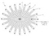
- FIG. 3is a radiation shielding device of the applicator of FIG. 2 ;
- FIG. 4is an electrical schematic diagram of an RF diathermy device
- FIG. 5is a lumped series tuned circuit model of the tuning circuit of FIG. 4 ;
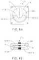
- FIG. 6Ais a plan view of the adjustable dielectric constant variable capacitor that can be used with the tuned circuit model of FIG. 5 ;
- FIG. 6Bis a cross-sectional view of the adjustable dielectric constant variable capacitor shown in FIG. 6A .
- a prior art flexible coil structure 1like the one shown in U.S. 2006/0119462, which is incorporated herein by reference, includes a secondary flexible coil structure 5 having a flexible, spiral-like winding which is physically coupled or positioned in spaced relation to a primary flexible coil structure 3 that also has a flexible, spiral-like winding, and a non-conductive spacer 4 disposed between and in contact with both primary flexible coil structure 3 and secondary flexible coil structure 5 .
- coil structures 3 , 5are two-dimensional spirals, each occupying a separate plane. Desirably, these separate planes are parallel to each other with spacer 4 disposed between and coupled to both coil structures 3 , 5 . Desirably, coil structures 3 , 5 have a common central axis 7 and are positioned in spaced relation along central axis 7 . In one, non-limiting embodiment, coil structures 3 , 5 include 18-gauge stranded silver-plated copper wire disposed on a sheet or substrate of insulative polytetrafluoroethylene (PTFE). Other types of wires and insulative sheets would also be acceptable.
- PTFEinsulative polytetrafluoroethylene
- FIG. 2a cross-sectional view of a radiation shielded diathermy applicator 9 coupled to a patient 12 or treatment target is depicted.
- the exterior of applicator 9is a non-conductive, flexible pouch 11 which allows applicator 9 to conform to a patient's chest, abdomen, back, and/or neck.
- pouch 11is made from nylon. However, this is not to be construed as limiting the invention.
- Applicator 9is in the form of a pad-shaped structure that includes a non-conductive layer 13 that separates pouch 11 from secondary flexible coil structure 5 contained within the pad structure of applicator 9 .
- Applicator 9also includes a non-conductive layer 14 that separates a radiation shield 17 (described hereinafter) from pouch 11 .
- Secondary flexible coil structure 5is embedded or disposed between layer 13 and spacer 4 .
- Primary flexible coil structure 3is embedded or disposed between spacer 4 and a non-conductive radiation shield spacer 15 .
- Spacer 4separates secondary flexible coil structure 5 from primary flexible coil structure 3 .
- Layer 13provides space between patient 12 and secondary flexible coil structure 5 when applicator 9 is being used by patient 12 .
- layer 13 , layer 14 , spacer 4 , and radiation shield spacer 15are each made from closed-cell polyethylene foams with thermoresistance, although other types of flexible, insulative material would also be acceptable.
- layer 13 , layer 14 and spacer 4are made of foam having a thickness of 9.525 mm
- radiation shield spacer 15is a foam layer having a thickness of 31.75 mm.
- other thicknesses and materialswould also be acceptable.
- radiation shield 17covers the non-patient facing side of radiation shield spacer 15 and has radial fingers 19 that curve around radiation shield spacer 15 , primary flexible coil structure 3 , spacer 4 , and connect to the patient-facing side of spacer 4 .
- Velcro® 21is used to connect each radial finger 19 to spacer 4 .
- thisis not to be construed as limiting the invention since it is envisioned that any other suitable and/or desirable means can be utilized to connect each finger to spacer 4 .
- a conductive pad 22At the end of each radial finger 19 is a conductive pad 22 that faces the body part of patient 12 under treatment when applicator 9 is worn by a patient.
- each pad 22provides capacitive coupling to the body of the patient 12 .
- Radiation shield 17also includes a conductive pad 24 which is coupled to a ground reference, e.g., a ground 31 sheath of coaxial cable 32 (shown in FIG. 4 ) in use of radiation shield 17 .
- Radiation shield 17includes conducting tracks 23 formed on a flexible printed circuit material made of a flexible, insulative substrate 25 . Conducting tracks 23 are also disposed on substrate 25 and electrically coupled to conductive pads 22 and conductive pad 24 .
- Non-limiting examples of materials that can be used for this substrateinclude FR-4, G-10, or Kapton®. Kapton® is a registered trademark of E.I. du Pont de Nemours and Company.
- radiation shield 17has the grid-like pattern of conducting tracks 23 shown in FIG. 3 . However, this is not to be construed as limiting the invention as it is envisioned that any suitable and/or desirable pattern having the same effect as the grid-like pattern shown in FIG. 3 can be used. It should also be noted that other materials could be substituted for substrate 25 provided that any such material has sufficient flexibility and dielectric strength.
- radiation shield 17adds only a small amount of stray capacitance across secondary flexible coil 5 while allowing electric field lines to terminate on the radiation shield conducting tracks 23 , which are coupled to a ground reference via conducting pad 24 coupled to the ground sheath 31 of coaxial cable 32 .
- radial fingers 19 of radiation shield 17remain constant in width as the radius of the radial fingers 19 increases radially from the center axis 27 of the radiation shield 17 .
- the pattern of radial fingers 19 on the peripheryallows the fingers to be curved around shield spacer 15 , primary flexible coil structure 3 , and spacer 4 .
- the conductive pads 22 at the ends of radial fingers 19define capacitive coupling elements that are positioned in spaced relation to the body tissue of patient 12 when applicator 9 is worn by the patient 12 .
- Each conductive pad 22acts as one plate of a capacitor, with the body tissue of patient 12 acting as a second plate of a capacitor, and layer 13 acting as a dielectric between each pad 22 and the body tissue of patient 12 .
- Conductive pads 22along with the body of patient 12 and layer 13 , form a capacitor which capacitively couples conductive tracks 23 to the patient's body 12 . More specifically, each conductive pad 22 spaced from the body of patient 12 by layer 13 acts as a separate capacitor in parallel with the combination of each of the other pads 22 spaced from the body of patient 12 by layer 13 . When multiple conductive pads 22 come into close proximity (spaced relation) with the body of patient 12 to form multiple parallel capacitors, these parallel capacitors act as a single large capacitor. Radiation shield 17 therefore avoids RF radiation fields from emanating to the surrounding environments by capacitively coupling these fields to the body of patient 12 .
- FIG. 4an electrical schematic diagram including supporting circuitry used with primary and secondary flexible coil structures 3 , 5 in an RF diathermy device 28 is shown.
- Resistor R pis a representation of the body of patient 12 .
- Inductor L 2is a representation of secondary flexible coil structure 5 and inductor L 1 is a representation of primary flexible coil structure 3 .
- Capacitor C 1is a representation of the capacitance that exists by the spacing among patient 12 , primary flexible coil structure 3 , and secondary flexible coil structure 5 .
- the capacitance of capacitor C 1may also include the capacitance of conductive pads 22 adjacent the body of patient 12 .
- Capacitor C 2is a variable capacitor that can be connected in parallel with R p and C 1 .
- Capacitor C 2enables tuning by matching the impedance of the combination of C 1 , C 2 , L 2 , and R p to the impedance of supporting circuitry so the same impedance can be realized throughout diathermy device 28 regardless of the patient 12 coupled to the device 28 .
- This impedance matchingallows the resonant frequency of the combination of C 1 , C 2 , L 2 , and R p to be about the same for each patient 12 that uses the device.
- An isolation device 29e.g. a balun transforms an unbalanced input signal on the L 3 side of device 29 into a balanced output signal on the L 4 side of device 29 , which output signal is supplied to primary flexible coil structure 3 .
- Isolation device 29acts to electrical isolate primary and secondary flexible coil structure 3 and 5 from a ground reference, such as, without limitation, the ground 31 of a 75 ohm coaxial cable 32 , whereupon primary and secondary flexible coil structures 3 and 5 can “float” relative to said ground reference.
- Coaxial cable 32connects the L 3 side of device 29 to an RF generator.
- a lumped, series tuned model circuit 33is depicted.
- the schematic depicted in FIG. 4 of RF diathermy applicator 28can be reduced to create model circuit 33 .
- resistor R prepresents patient 12 ;
- variable capacitor 30represents the lumped capacitance of applicator 28 , including variable capacitor C 2 ;
- variable inductor 29represents the lumped inductance of applicator 28 , and resistor 35 represents the lumped resistance of applicator 28 .
- These elementsare connected to an RF generator (not shown) via coaxial cable 32 .
- the tuning range of model circuit 33may be selected so as to avoid resonance when body tissue is not coupled to applicator 9 .
- a resistive value R s of resistor 35changes with tissue loading. Specifically, resistive value R, is lower when resistor 35 is unloaded and is higher when resistor 35 is “heavily loaded”. Resistive value R s changes over a range of about 2:1 in practice and the resulting currents and voltages across the tuning circuit elements can then also be expected to vary as much as 2:1 at resonance and even more at detuned conditions.
- resistor 35simplifies into a 50 ohm resistor. With 35 watts present, this represents a voltage of about 42 Volts rms and a current of 42/50 ⁇ 0.84 Amps.
- variable capacitor C 2includes a moveable section of two low-loss dielectric materials 37 , 39 that cause the average dielectric constant between the fixed metal plates (Contact A and Contact B) of capacitor C 2 to vary over a two-to-one range as the moveable section is rotated or moved between Contact A and Contact B.
- the materials 37 , 39 selected in this particular embodimentare Teflon® and Noryl®, with approximate dielectric constants of 2 and 4, respectively. Teflon® is a registered trademark of E.I. du Pont de Nemours and Company.
- Noryl®is a registered trademark of Saudi Basic Industries Corporation (SABIC). It should be noted that other materials could be substituted for either of materials 37 , 39 , depending on the range of capacitance desired. Use of these materials avoids the need for the metal plates (i.e., Contact A and Contact B) to have a moveable electrical contact, greatly improving reliability and lowering cost.
- the construction of variable capacitor C 2 in one embodimentis a circular design. It should be noted that other mechanical arrangements (for example a linear array) could be utilized without affecting the intended scope of this invention.
- Variable capacitor C 2is used to tune the radio frequency of RF diathermy device 28 to resonance, the value of which depends upon stray capacitances across secondary flexible coil structure 5 .
- the transformed impedance caused by variable capacitor C 2varies from inductive to resistive and then to capacitive as the stray capacitances change and as variable capacitor C 2 is adjusted.
Landscapes
- Health & Medical Sciences (AREA)
- Engineering & Computer Science (AREA)
- Biomedical Technology (AREA)
- Nuclear Medicine, Radiotherapy & Molecular Imaging (AREA)
- Radiology & Medical Imaging (AREA)
- Life Sciences & Earth Sciences (AREA)
- Animal Behavior & Ethology (AREA)
- General Health & Medical Sciences (AREA)
- Public Health (AREA)
- Veterinary Medicine (AREA)
- Radiation-Therapy Devices (AREA)
- Surgical Instruments (AREA)
Abstract
Description
Claims (8)
Priority Applications (1)
| Application Number | Priority Date | Filing Date | Title |
|---|---|---|---|
| US12/796,778US8489201B2 (en) | 2009-06-09 | 2010-06-09 | Shielded diathermy applicator with automatic tuning and low incidental radiation |
Applications Claiming Priority (2)
| Application Number | Priority Date | Filing Date | Title |
|---|---|---|---|
| US18539309P | 2009-06-09 | 2009-06-09 | |
| US12/796,778US8489201B2 (en) | 2009-06-09 | 2010-06-09 | Shielded diathermy applicator with automatic tuning and low incidental radiation |
Publications (2)
| Publication Number | Publication Date |
|---|---|
| US20110060391A1 US20110060391A1 (en) | 2011-03-10 |
| US8489201B2true US8489201B2 (en) | 2013-07-16 |
Family
ID=43309453
Family Applications (1)
| Application Number | Title | Priority Date | Filing Date |
|---|---|---|---|
| US12/796,778Active2031-03-11US8489201B2 (en) | 2009-06-09 | 2010-06-09 | Shielded diathermy applicator with automatic tuning and low incidental radiation |
Country Status (2)
| Country | Link |
|---|---|
| US (1) | US8489201B2 (en) |
| WO (1) | WO2010144548A2 (en) |
Cited By (1)
| Publication number | Priority date | Publication date | Assignee | Title |
|---|---|---|---|---|
| US20160256704A1 (en)* | 2015-03-02 | 2016-09-08 | KAIO Therapy, LLC | Systems and methods for providing alternating magnetic field therapy |
Families Citing this family (25)
| Publication number | Priority date | Publication date | Assignee | Title |
|---|---|---|---|---|
| US8500732B2 (en) | 2008-10-21 | 2013-08-06 | Hermes Innovations Llc | Endometrial ablation devices and systems |
| US8821486B2 (en) | 2009-11-13 | 2014-09-02 | Hermes Innovations, LLC | Tissue ablation systems and methods |
| US8197477B2 (en) | 2008-10-21 | 2012-06-12 | Hermes Innovations Llc | Tissue ablation methods |
| US8197476B2 (en) | 2008-10-21 | 2012-06-12 | Hermes Innovations Llc | Tissue ablation systems |
| US8540708B2 (en) | 2008-10-21 | 2013-09-24 | Hermes Innovations Llc | Endometrial ablation method |
| US8382753B2 (en) | 2008-10-21 | 2013-02-26 | Hermes Innovations, LLC | Tissue ablation methods |
| US9662163B2 (en) | 2008-10-21 | 2017-05-30 | Hermes Innovations Llc | Endometrial ablation devices and systems |
| US8715278B2 (en)* | 2009-11-11 | 2014-05-06 | Minerva Surgical, Inc. | System for endometrial ablation utilizing radio frequency |
| US9289257B2 (en) | 2009-11-13 | 2016-03-22 | Minerva Surgical, Inc. | Methods and systems for endometrial ablation utilizing radio frequency |
| US8529562B2 (en) | 2009-11-13 | 2013-09-10 | Minerva Surgical, Inc | Systems and methods for endometrial ablation |
| US11896282B2 (en) | 2009-11-13 | 2024-02-13 | Hermes Innovations Llc | Tissue ablation systems and method |
| US8956348B2 (en) | 2010-07-21 | 2015-02-17 | Minerva Surgical, Inc. | Methods and systems for endometrial ablation |
| US9510897B2 (en) | 2010-11-05 | 2016-12-06 | Hermes Innovations Llc | RF-electrode surface and method of fabrication |
| US9867996B2 (en) | 2011-11-16 | 2018-01-16 | Btl Holdings Limited | Methods and systems for skin treatment |
| US9901394B2 (en) | 2013-04-04 | 2018-02-27 | Hermes Innovations Llc | Medical ablation system and method of making |
| US9802057B2 (en)* | 2013-05-22 | 2017-10-31 | Viatherm Therapeutics LLC | Universal diathermy heat applicator |
| US9649125B2 (en) | 2013-10-15 | 2017-05-16 | Hermes Innovations Llc | Laparoscopic device |
| US10492856B2 (en) | 2015-01-26 | 2019-12-03 | Hermes Innovations Llc | Surgical fluid management system and method of use |
| CN107708591B (en) | 2015-04-29 | 2020-09-29 | 席勒斯科技有限公司 | Medical ablation device and method of use |
| US20160346560A1 (en)* | 2015-05-26 | 2016-12-01 | Regear Life Sciences Inc. | Diathermy Heat Applicator Array with Cancellation of Extraneous Incidental Radiation |
| US10052149B2 (en) | 2016-01-20 | 2018-08-21 | RELIGN Corporation | Arthroscopic devices and methods |
| CN109561899A (en) | 2016-04-22 | 2019-04-02 | 锐凌公司 | Arthroscope device and method |
| CN109661209A (en) | 2016-07-01 | 2019-04-19 | 锐凌公司 | Arthroscope device and method |
| US11554214B2 (en) | 2019-06-26 | 2023-01-17 | Meditrina, Inc. | Fluid management system |
| US20230126722A1 (en)* | 2020-03-12 | 2023-04-27 | Best Medical International, Inc. | Radiotherapy applicator system |
Citations (11)
| Publication number | Priority date | Publication date | Assignee | Title |
|---|---|---|---|---|
| US4068292A (en) | 1975-03-27 | 1978-01-10 | International Medical Electronics, Inc. | Electrostatic shield for diathermy treatment head |
| US5107832A (en) | 1991-03-11 | 1992-04-28 | Raul Guibert | Universal thermotherapy applicator |
| US5160828A (en) | 1990-03-06 | 1992-11-03 | The United States Of America As Represented By The Secretary Of The Navy | Electromagnetic warming of submerged extremities |
| US6094599A (en) | 1998-03-24 | 2000-07-25 | Ehti Medical Corporation | RF diathermy and faradic muscle stimulation treatment |
| US20020040233A1 (en) | 1998-01-15 | 2002-04-04 | George Frank R. | Pulsed electromagnetic energy treatment apparatus and method |
| US6471695B1 (en)* | 2000-09-06 | 2002-10-29 | Radiotherapeutics, Inc. | Apparatus and method for shielding tissue during tumor ablation |
| US20040119033A1 (en) | 1999-09-17 | 2004-06-24 | George Frank R. | Cover for electromagnetic treatment applicator |
| US6853865B2 (en) | 2002-09-04 | 2005-02-08 | Selicor, Inc. | Apparatus for RF diathermy treatment |
| US20060119462A1 (en) | 2004-12-02 | 2006-06-08 | Selicor, Inc. | Radio frequency diathermy application system and device |
| US7769468B2 (en)* | 2006-03-03 | 2010-08-03 | Bsd Medical Corporation | Transparent electromagnetic applicator and hyperthermia treatment method |
| US20100305560A1 (en)* | 2009-05-29 | 2010-12-02 | Vivant Medical, Inc. | Microwave Ablation Safety Pad, Microwave Safety Pad System and Method of Use |
Family Cites Families (28)
| Publication number | Priority date | Publication date | Assignee | Title |
|---|---|---|---|---|
| IT610737A (en) | 1955-11-18 | 1900-01-01 | ||
| US3661744A (en) | 1966-07-26 | 1972-05-09 | Grace W R & Co | Photocurable liquid polyene-polythiol polymer compositions |
| US4181752A (en) | 1974-09-03 | 1980-01-01 | Minnesota Mining And Manufacturing Company | Acrylic-type pressure sensitive adhesives by means of ultraviolet radiation curing |
| US4303485A (en) | 1979-08-20 | 1981-12-01 | Minnesota Mining And Manufacturing Company | Ultraviolet polymerization of acrylate monomers using oxidizable tin compounds |
| US4436858A (en) | 1982-05-14 | 1984-03-13 | Hercules Incorporated | Plasticized polydicyclopentadiene and a method for making the same |
| US4619979A (en) | 1984-03-28 | 1986-10-28 | Minnesota Mining And Manufacturing Company | Continuous free radial polymerization in a wiped-surface reactor |
| US5506300A (en) | 1985-01-04 | 1996-04-09 | Thoratec Laboratories Corporation | Compositions that soften at predetermined temperatures and the method of making same |
| US4737559A (en) | 1986-05-19 | 1988-04-12 | Minnesota Mining And Manufacturing Co. | Pressure-sensitive adhesive crosslinked by copolymerizable aromatic ketone monomers |
| US4808638A (en) | 1986-10-14 | 1989-02-28 | Loctite Corporation | Thiolene compositions on based bicyclic 'ene compounds |
| JP2502132B2 (en) | 1988-09-30 | 1996-05-29 | 三菱重工業株式会社 | Shape memory polyurethane elastomer molded body |
| JPH02121907A (en) | 1988-10-31 | 1990-05-09 | Mitsubishi Heavy Ind Ltd | Cosmetic for human |
| JP2959775B2 (en) | 1988-11-11 | 1999-10-06 | 日本ゼオン株式会社 | Material for shape memory molding |
| JPH0832766B2 (en) | 1988-12-07 | 1996-03-29 | 帝人株式会社 | Shape memory cross-linked polymer molded article and method for producing the same |
| US5459175A (en) | 1990-11-28 | 1995-10-17 | Loctite Corporation | Optical fiber primary coatings and fibers coated therewith |
| US5665822A (en) | 1991-10-07 | 1997-09-09 | Landec Corporation | Thermoplastic Elastomers |
| EP0498602A3 (en) | 1991-02-06 | 1992-10-07 | Nippon Zeon Co., Ltd. | Composite molding and production process and use thereof |
| US5182360A (en) | 1991-10-17 | 1993-01-26 | Loctite Corporation | Tris(norbornenyl) isocyanurate |
| JP2686589B2 (en) | 1993-10-28 | 1997-12-08 | 富士高分子株式会社 | Method for producing curable resin-impregnated expandable sheet material |
| US5512612A (en) | 1994-04-04 | 1996-04-30 | Minnesota Mining And Manufacturing Company | Pressure sensitive adhesive employing a water-dispersible polymer and articles made there from |
| US5804610A (en) | 1994-09-09 | 1998-09-08 | Minnesota Mining And Manufacturing Company | Methods of making packaged viscoelastic compositions |
| US5637646A (en) | 1995-12-14 | 1997-06-10 | Minnesota Mining And Manufacturing Company | Bulk radical polymerization using a batch reactor |
| ATE266434T1 (en) | 1998-02-23 | 2004-05-15 | Massachusetts Inst Technology | BIODEGRADABLE POLYMERS WITH SHAPE MEMORY |
| DE69931474T2 (en) | 1998-02-23 | 2007-05-10 | Mnemoscience Gmbh | SHAPE MEMORY POLYMER |
| EP1226742B1 (en) | 1999-11-03 | 2006-12-27 | Nexicor, LLC | Hand held induction tool |
| US20050244353A1 (en) | 2002-04-10 | 2005-11-03 | Mnemoscience Gmbh | Method for achieving shape memory effects on hair by combining shape memory polymers with cationic active ingredients |
| US20040030062A1 (en) | 2002-05-02 | 2004-02-12 | Mather Patrick T. | Castable shape memory polymers |
| WO2004033553A1 (en) | 2002-10-11 | 2004-04-22 | University Of Connecticut | Crosslinked polycyclooctene |
| DE10334784A1 (en) | 2003-07-30 | 2005-03-03 | Mnemoscience Gmbh | Cosmetic composition with polyol / polyester block polymers |
- 2010
- 2010-06-09WOPCT/US2010/037933patent/WO2010144548A2/enactiveApplication Filing
- 2010-06-09USUS12/796,778patent/US8489201B2/enactiveActive
Patent Citations (14)
| Publication number | Priority date | Publication date | Assignee | Title |
|---|---|---|---|---|
| US4068292A (en) | 1975-03-27 | 1978-01-10 | International Medical Electronics, Inc. | Electrostatic shield for diathermy treatment head |
| US5160828A (en) | 1990-03-06 | 1992-11-03 | The United States Of America As Represented By The Secretary Of The Navy | Electromagnetic warming of submerged extremities |
| US5107832A (en) | 1991-03-11 | 1992-04-28 | Raul Guibert | Universal thermotherapy applicator |
| US20020040233A1 (en) | 1998-01-15 | 2002-04-04 | George Frank R. | Pulsed electromagnetic energy treatment apparatus and method |
| US6735481B1 (en) | 1998-03-24 | 2004-05-11 | Ehti Medical Corporation | RF diathermy and faradic muscle stimulation treatment |
| US6094599A (en) | 1998-03-24 | 2000-07-25 | Ehti Medical Corporation | RF diathermy and faradic muscle stimulation treatment |
| US20040230226A1 (en) | 1998-03-24 | 2004-11-18 | Ehti Medical Corporation | RF diathermy and faradic muscle stimulation treatment |
| US20080215115A1 (en) | 1998-03-24 | 2008-09-04 | Coventina Healthcare Enterprises, Inc. | RF Diathermy and Faradic Muscle Stimulation Treatment |
| US20040119033A1 (en) | 1999-09-17 | 2004-06-24 | George Frank R. | Cover for electromagnetic treatment applicator |
| US6471695B1 (en)* | 2000-09-06 | 2002-10-29 | Radiotherapeutics, Inc. | Apparatus and method for shielding tissue during tumor ablation |
| US6853865B2 (en) | 2002-09-04 | 2005-02-08 | Selicor, Inc. | Apparatus for RF diathermy treatment |
| US20060119462A1 (en) | 2004-12-02 | 2006-06-08 | Selicor, Inc. | Radio frequency diathermy application system and device |
| US7769468B2 (en)* | 2006-03-03 | 2010-08-03 | Bsd Medical Corporation | Transparent electromagnetic applicator and hyperthermia treatment method |
| US20100305560A1 (en)* | 2009-05-29 | 2010-12-02 | Vivant Medical, Inc. | Microwave Ablation Safety Pad, Microwave Safety Pad System and Method of Use |
Cited By (2)
| Publication number | Priority date | Publication date | Assignee | Title |
|---|---|---|---|---|
| US20160256704A1 (en)* | 2015-03-02 | 2016-09-08 | KAIO Therapy, LLC | Systems and methods for providing alternating magnetic field therapy |
| US10500409B2 (en)* | 2015-03-02 | 2019-12-10 | KAIO Therapy, LLC | Systems and methods for providing alternating magnetic field therapy |
Also Published As
| Publication number | Publication date |
|---|---|
| US20110060391A1 (en) | 2011-03-10 |
| WO2010144548A3 (en) | 2011-03-31 |
| WO2010144548A2 (en) | 2010-12-16 |
Similar Documents
| Publication | Publication Date | Title |
|---|---|---|
| US8489201B2 (en) | Shielded diathermy applicator with automatic tuning and low incidental radiation | |
| KR101387841B1 (en) | Mri compatible electrode circuit | |
| US8666513B2 (en) | Implantable lead with shielding | |
| US7917213B2 (en) | MRI compatible implanted electronic medical lead | |
| JP5073829B2 (en) | Implantable lead with variable coil conductor pitch | |
| JPH0527069B2 (en) | ||
| US12412979B2 (en) | Antenna device and communication terminal apparatus | |
| CN104422912B (en) | Antenna device for receiving magnetic resonance signals | |
| US20230200904A1 (en) | Apparatus for application of evanescent waves to biological tissues | |
| US8805540B2 (en) | MRI compatible cable | |
| US4823811A (en) | Electrostatic deep heating applicator | |
| US8761899B2 (en) | MRI compatible conductive wires | |
| KR101825279B1 (en) | Mri compatible electrode circuit | |
| US9802057B2 (en) | Universal diathermy heat applicator | |
| US8831743B2 (en) | MRI compatible electrode circuit | |
| CN114976658A (en) | MRI system and RF transmitting antenna device | |
| CN114910838B (en) | Magnetic field enhancement assembly and magnetic field enhancement device | |
| US20220125510A1 (en) | Apparatus for application of evanescent waves to biological tissues | |
| CN114910843B (en) | Magnetic field enhancement device | |
| CA2902564C (en) | Mri compatible electrode circuit | |
| WO2013188227A1 (en) | Mri compatible conductive wires | |
| CN114910847A (en) | Magnetic field enhancement components and magnetic field enhancement devices | |
| HK1217096B (en) | Mri compatible electrode circuit |
Legal Events
| Date | Code | Title | Description |
|---|---|---|---|
| AS | Assignment | Owner name:REGEAR LIFE SCIENCES, INC., PENNSYLVANIA Free format text:ASSIGNMENT OF ASSIGNORS INTEREST;ASSIGNORS:UNETICH, ROBERT M.;HANLON, JAMES;SIGNING DATES FROM 20100924 TO 20101030;REEL/FRAME:025420/0244 | |
| AS | Assignment | Owner name:GENERAL ELECTRIC CAPITAL CORPORATION, MARYLAND Free format text:SECURITY AGREEMENT;ASSIGNOR:REGEAR LIFE SCIENCES, INC.;REEL/FRAME:029005/0109 Effective date:20120824 | |
| STCF | Information on status: patent grant | Free format text:PATENTED CASE | |
| AS | Assignment | Owner name:REGEAR LIFE SCIENCES, LLC, PENNSYLVANIA Free format text:CHANGE OF NAME;ASSIGNOR:REGEAR LIFE SCIENCES, INC.;REEL/FRAME:034262/0413 Effective date:20141120 | |
| FPAY | Fee payment | Year of fee payment:4 | |
| AS | Assignment | Owner name:VIATHERM THERAPEUTICS, LLC, MARYLAND Free format text:ASSIGNMENT OF ASSIGNORS INTEREST;ASSIGNOR:REGEAR LIFE SCIENCES, INC.;REEL/FRAME:051204/0440 Effective date:20180101 | |
| FEPP | Fee payment procedure | Free format text:MAINTENANCE FEE REMINDER MAILED (ORIGINAL EVENT CODE: REM.); ENTITY STATUS OF PATENT OWNER: SMALL ENTITY | |
| FEPP | Fee payment procedure | Free format text:7.5 YR SURCHARGE - LATE PMT W/IN 6 MO, SMALL ENTITY (ORIGINAL EVENT CODE: M2555); ENTITY STATUS OF PATENT OWNER: SMALL ENTITY | |
| MAFP | Maintenance fee payment | Free format text:PAYMENT OF MAINTENANCE FEE, 8TH YR, SMALL ENTITY (ORIGINAL EVENT CODE: M2552); ENTITY STATUS OF PATENT OWNER: SMALL ENTITY Year of fee payment:8 | |
| MAFP | Maintenance fee payment | Free format text:PAYMENT OF MAINTENANCE FEE, 12TH YR, SMALL ENTITY (ORIGINAL EVENT CODE: M2553); ENTITY STATUS OF PATENT OWNER: SMALL ENTITY Year of fee payment:12 |