US8488936B2 - Fiber retainer for cable trough member - Google Patents
Fiber retainer for cable trough memberDownload PDFInfo
- Publication number
- US8488936B2 US8488936B2US12/763,268US76326810AUS8488936B2US 8488936 B2US8488936 B2US 8488936B2US 76326810 AUS76326810 AUS 76326810AUS 8488936 B2US8488936 B2US 8488936B2
- Authority
- US
- United States
- Prior art keywords
- trough
- retainer
- cable
- coupled
- sidewall
- Prior art date
- Legal status (The legal status is an assumption and is not a legal conclusion. Google has not performed a legal analysis and makes no representation as to the accuracy of the status listed.)
- Expired - Fee Related, expires
Links
Images


Classifications
- G—PHYSICS
- G02—OPTICS
- G02B—OPTICAL ELEMENTS, SYSTEMS OR APPARATUS
- G02B6/00—Light guides; Structural details of arrangements comprising light guides and other optical elements, e.g. couplings
- G02B6/44—Mechanical structures for providing tensile strength and external protection for fibres, e.g. optical transmission cables
- G02B6/4439—Auxiliary devices
- G02B6/4459—Ducts; Conduits; Hollow tubes for air blown fibres
Definitions
- optical fibersfor signal transmissions
- optical fiber cable managementrequires industry attention.
- optical fiber managementOne area of optical fiber management that is necessary is the routing of optical fibers from one piece of equipment to another.
- optical fiber cablesmay be routed between fiber distribution equipment and optical line terminating equipment.
- the cable routingcan take place in concealed ceiling areas or in any other manner to route cables from one location to another.
- routing systemsWhen routing optical fibers and other cables such as copper wires, it is desirable that a routing system will be readily modifiable and adaptable to changes in equipment needs. Accordingly, such routing systems include a plurality of components, such as trough members and couplers, for defining the cable routing paths. The trough members are joined together by couplers.
- U.S. Pat. Nos. 5,067,678; 5,316,243; and 5,752,781teach cable routing systems that include a plurality of trough members and couplers.
- trough membersit can be desirable to easily route cables into and out of the trough members.
- the open endscan allow fiber to potentially escape from the trough members. Even if the trough members include covers to close the open ends, it may be necessary to periodically gain access to the interior portions of the trough members to, for example, add or remove fibers.
- Embodiments of the present disclosureare directed to systems and methods for the management and routing of telecommunication cables and, more particularly, to cable trough members.
- the trough membersinclude a plurality of retainer members coupled to sidewalls of the trough members.
- the retainer membersassist in maintaining cables within an interior of the trough members.
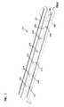
- FIG. 1is a perspective view of an example cable routing system.
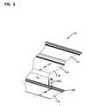
- FIG. 2is a perspective view of a portion of the cable routing system of FIG. 1 .
- FIG. 3is an end view of a portion of the cable routing system of FIG. 1 .
- FIG. 4is a side view of a sidewall of an example trough member of the portion of the cable routing system of FIG. 3 .
- FIG. 5is an end view of another portion of the cable routing system of FIG. 1 .
- FIG. 6is an end view of an example retainer member of the cable routing system of FIG. 1 .
- FIG. 7is a side view of the retainer member of FIG. 6 .
- FIG. 8is another side view of the retainer member of FIG. 6 .
- FIG. 9is an end view of another portion of the cable routing system of FIG. 1 .
- FIG. 10is another end view of another portion of the cable routing system of FIG. 1 .
- FIG. 11is a perspective view of another example retainer member.
- FIG. 12is an end view of the retainer member of FIG. 11 .
- FIG. 13is a side view of the retainer member of FIG. 11 .
- FIG. 14is a side view of a portion of another example trough member.
- FIG. 15is a side view of another portion of the trough member of FIG. 14 .
- FIG. 16is a perspective view of a portion of the trough member of FIG. 15 .
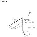
- FIG. 17is a perspective view of another example retainer member.
- FIG. 18is another perspective view of the retainer member of FIG. 17 .
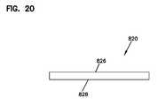
- FIG. 19is a top view of an example mounting member.
- FIG. 20is a side view of the mounting member of FIG. 19 .
- Embodiments of the present disclosureare directed to systems and methods for the management and routing of telecommunication cables and, more particularly, to cable trough members.
- the trough membersinclude a plurality of retainer members coupled to sidewalls of the trough members.
- the retainer membersassist in maintaining cables within an interior of the trough members.
- trough memberis used to refer to any trough, fitting, railway, raceway, or similarly configured component including any number of ends.
- the trough memberscan be positioned to extend vertically or horizontally.
- FIGS. 1-10an example embodiment of a cable routing system 101 including a trough member 100 is shown.
- the example trough member 100includes first and second sidewalls 112 and 116 coupled to a third wall 114 generally forming a U-shaped trough with an interior space 118 through which cables 119 such as fiber can be run.
- the trough member 100extends lengthwise in a vertical or horizontal direction when in use.
- the trough member 100extends from a first end 111 to a second end 113 .
- the trough member 100can be of varying lengths and widths, and can be coupled to other trough members or similar structures to form the cable routing system 101 .
- Each of the free ends of the sidewalls 112 , 116includes a hinge portion 120 .
- the hinge portion 120is used to allow a cover 121 to be coupled to the trough member 100 .
- the cover 121can be coupled to the hinge portions 120 and can be moved between closed and open positions.
- the trough member 100also includes a plurality of retainer members 202 , 204 , 206 , 208 , 210 , 212 , 214 , 216 , 218 , 220 , 222 (collectively referred to as “retainer members”).
- the retainer membersare coupled to the sidewalls 112 , 116 .
- the retainer membersassist in maintaining the cables 119 within the interior 118 of the trough member 100 .
- the retainer members 212 , 214are coupled to sidewalls 112 , 116 , respectively.
- the retainer members 212 , 214extend towards one another to cover a portion of the open end of the trough member 100 .
- a space 232 formed between the retainer members 212 , 214allows the cables 119 to enter and exit the interior 118 .
- the space 232is smaller than the opening of the trough member 100 to assist in cable retention when the cover 121 is in the open position.
- the sidewall 112includes a plurality of openings 302 , 304 , 306 , 308 , 310 formed in a line along the sidewall 112 .
- the openings 302 , 304 , 306 , 308 , 310are formed at periodic intervals along the sidewalls 112 , 116 .
- the openings 302 , 306 , 310are “keyhole-shaped” to include a smaller diameter aperture 312 in communication with a larger diameter aperture 314 .
- the openings 302 , 304 , 306 , 308 , 310allow the retainer members to be coupled to the sidewalls 112 , 116 in a variety of manners.
- FIG. 5another portion of the trough member 100 is shown.
- the retainer member 220extends farther across the opening of the trough member 100 so that an opening 234 formed between the retainer members 220 , 222 is smaller than the opening 232 .
- Other configurations, as described below,are possible.
- the retainer member 220includes a first portion 402 and a second portion 404 .
- the first portion 402is coupled to the second portion 404 at an angle (e.g., a right angle or another obtuse angle) so that the retainer member 220 forms an “L” shape.
- the first and second portions 402 , 404each include locking members 406 and detent members 412 .
- Two locking members 406are provided on each of the first and second portions 402 , 404 .
- the locking members 406each include a head portion 408 and a stem portion 410 .
- the head portion 408 of each of the locking members 406 on either of the first and second portions 402 , 404is sized to fit into and through the larger diameter apertures 314 of two adjacent ones of the openings 302 , 306 , 310 in the sidewalls 112 , 116 of the trough member.
- the stem portions 410can be slid into the smaller diameter apertures 312 .
- the head portions 408are too large to fit through the smaller diameters apertures 312 .
- the detent member 412when moved into this locked position, the detent member 412 is positioned in the respective opening 304 , 308 on the sidewall 112 , 116 . In this locked position, the retainer member 220 is coupled to the respective sidewall 112 , 116 .
- either the first portion 402 or the second portion 404can be coupled to the respectively sidewall 112 , 116 , since both portions include the locking members 406 and detent members 412 . This can be advantageous, for example, when the first and second portions 402 , 404 are different lengths.
- a length 401 of first portion 402is shorter than a length 403 the second portion 404 .
- the second portion 404can be coupled to the respective sidewall 112 , 116 , thereby allowing the shorter first portion 402 to extend into the interior 118 of the trough member 100 .
- the first portion 402can be coupled to the respective sidewall 112 , 116 , thereby allowing the longer second portion 404 to extend into the interior 118 of the trough member 100 .
- Other configurationsare possible.
- FIG. 9another portion of the trough member 100 is shown.
- the retainer member 216is mounted in the first two openings 302 , 306 on the sidewall 112
- the retainer member 218is mounted in the second two openings 306 , 308 on the sidewall 116 .
- the cable that is positioned within the interior 118 of the trough member 100must be moved through this opening 510 in a zigzag or tortuous path to remove the cable, thereby further maintaining the cable in the trough member 100 .
- retainer members 204 , 206are shown.
- the retainer member 206is inverted when the retainer member 206 is mounted to the sidewall 116 .
- the locking members 406 of the retainer member 206can be placed in the openings 302 , 306 , 310 formed on sidewall 116 to mount the retainer member 206 .
- the resulting configurationis a central channel 502 formed between the retainer members 204 , 206 . Cables can be routed through this central channel 502 , if desired.
- the retainer memberscan be inverted when mounted to the sidewalls 112 , 116 because the distances 482 , 484 between the locking members 406 and the detent member 412 are equal on each portion of the retainer members. See FIG. 6 .
- the distances 482 , 484can be configured to be different (and the placement of the mating openings 302 , 304 , 306 , 308 , 310 on the sidewalls 112 , 116 correspondingly modified as well) so that the retainer members can only be coupled to the sidewalls 112 , 116 in one orientation.
- retainer membersare selected based on the need for cable retainment. For example, if greater retainment is needed, retainer members having a longer first or second portion can be selected so that the resulting exposed opening in the trough member is smaller.
- the retainer membersare mounted to the sidewalls of the trough member at the desired position, height, and orientation. This is accomplished by placing the locking members of each of the retainer members in the two openings at the desired position, height, and orientation. The retainer member is then moved so that the locking members are slid into the narrower portion of the openings and the detent member is received in the mid-point opening on the sidewall. In this position, the retainer member is mounted to the sidewall. Multiple retainer members can be mounted at different positions along the trough member, at different heights, and at different orientations to accomplish the desired retainment.
- each retainer memberis grasped and pulled slightly away from the sidewall. This moves the detent member out of the opening in the sidewall. At this point, the retainer member can be slid relative to the sidewall so that the locking members move to the wider portions of the openings in the sidewalls. The locking members can then pass through the wider portions of the openings, and the retainer member can then be removed from the sidewall.
- FIGS. 11-13another embodiment of a retainer member 600 is shown.
- the retainer member 600is similar to that of the retainer members described above, except that the retainer member 600 only includes locking members 406 and the detent member 412 on a first portion 602 of the retainer member 600 .
- the second portion 604does not include any locking members or detents. In this configuration, only the first portion 602 of the retainer member 600 can be mounted to the sidewalls 112 , 116 of the trough member 100 .
- the second portion 604 of the retainer member 600also includes an angled end portion 622 .
- the angled end portion 622can be mated with a corresponding retainer member mounted to the opposite sidewall of the trough member to form an opening that is angled with respect to the longitudinal direction of the trough member.
- the trough member 700is similar to the trough member 100 , except that sidewalls of the trough member 700 are slotted instead of being solid like the trough member 100 .
- the trough member 700includes a plurality of slots 715 formed in the sidewalls 712 , 716 .
- the slots 715are sized to allow cable to enter or exit the interior space of the trough member 700 through the slots 715 .
- the slots 715are formed at periodic intervals along the sidewalls 712 , 716 . Other configurations are possible.
- the trough member 700also includes the openings 302 , 304 , 306 , 308 , 310 formed in a line along the sidewalls 712 , 716 .
- the openings 302 , 304 , 306 , 308 , 310are formed at periodic intervals along the sidewalls 712 , 716 between adjacent slots 715 .
- the openings 302 , 304 , 306 , 308 , 310allow the retainer members to be coupled to the sidewalls 712 , 716 , as shown in FIG. 16 .
- the retainer member 800is similar to that of the retainer members described above, except that the retainer member 800 does not have any locking members 406 and detent members 412 on first and second portions 802 , 804 of the retainer member 800 . Instead, the retainer member 800 includes mounting surfaces 806 , 808 that are sized to receive a mounting member 820 .
- the mounting member 820is a double-sided piece of adhesive tape that can be used to mount the retainer member 800 to the sidewalls of the trough members 100 , 700 .
- the mounting surfaces 806 , 808include dimensions 810 , 812 and 814 , 812 , respectively.
- the dimensions 806 , 808 , 810 , 812can be sized to receive the mounting member 820 , which includes dimensions 822 , 824 .
- the mounting member 820includes first and second sides 826 , 828 .
- Each of the sides 826 , 828includes a mounting substance, such as an adhesive like glue.
- One of the sides 826 , 828can be coupled to one of the mounting surfaces 806 , 808 , and the other of the sides 826 , 828 can be mounted to one of the sidewalls of the trough members 100 , 700 .
- the mounting member 820is affixed to one of the mounting surfaces 806 , 808 when assembled, and the user can remove a release liner and mount the retainer member 800 to one of the sidewalls of the trough members 100 , 700 when in use.
- the mounting member 820can be provided separate from the retainer member 800 . The user can decide which of the first and second portions 802 , 804 to mount the mounting member 820 .
- the dimensions 810 , 812 of the mounting surface 806 on the first portion 802can differ from the dimensions 814 , 816 of the mounting surface 808 of the second portion 808 .
- the dimensions 822 , 824 of the mounting member 820can be sized to correspond to one of the dimensions 810 , 812 of the mounting surface 806 or the dimensions 814 , 816 of the mounting surface 808 .
- the mounting surface 804 , 806need not be defined on the first and second portions 802 , 804 . Instead, the mounting member 820 can be placed anywhere on the surface of the mounting surfaces 804 , 806 .
- gluecan be applied directly to the first or second portions 802 , 804 to mount the respective portion 802 , 804 to one of the sidewalls of the trough members 100 , 700 .
- the trough membersare extruded from a synthetic thermoplastic polymer such as an acrylonitrile-butadiene-styrene(ABS)/polycarbonate blend.
- a synthetic thermoplastic polymersuch as an acrylonitrile-butadiene-styrene(ABS)/polycarbonate blend.
- ABSacrylonitrile-butadiene-styrene
- Other manufacturing methodse.g., molding
- materialscan also be used.
- the openings in the sidewalls of the trough members for receiving the locking members and detent memberscan be formed by punching the sidewalls of the trough members at the desired periodic intervals.
- the slots in the trough member 700can be formed by punching and/or cutting the slots into the sidewalls of the trough member.
- the retainer memberscan be made of from a synthetic thermoplastic polymer such as an acrylonitrile-butadiene-styrene(ABS)/polycarbonate blend.
- the retainer memberscan be formed using various manufacturing techniques, such as by injection molding. Other manufacturing techniques and materials can be used.
Landscapes
- Physics & Mathematics (AREA)
- General Physics & Mathematics (AREA)
- Optics & Photonics (AREA)
- Laying Of Electric Cables Or Lines Outside (AREA)
Abstract
Description
Claims (17)
Priority Applications (1)
| Application Number | Priority Date | Filing Date | Title |
|---|---|---|---|
| US12/763,268US8488936B2 (en) | 2009-04-20 | 2010-04-20 | Fiber retainer for cable trough member |
Applications Claiming Priority (2)
| Application Number | Priority Date | Filing Date | Title |
|---|---|---|---|
| US17087509P | 2009-04-20 | 2009-04-20 | |
| US12/763,268US8488936B2 (en) | 2009-04-20 | 2010-04-20 | Fiber retainer for cable trough member |
Publications (2)
| Publication Number | Publication Date |
|---|---|
| US20100266256A1 US20100266256A1 (en) | 2010-10-21 |
| US8488936B2true US8488936B2 (en) | 2013-07-16 |
Family
ID=42981036
Family Applications (1)
| Application Number | Title | Priority Date | Filing Date |
|---|---|---|---|
| US12/763,268Expired - Fee RelatedUS8488936B2 (en) | 2009-04-20 | 2010-04-20 | Fiber retainer for cable trough member |
Country Status (1)
| Country | Link |
|---|---|
| US (1) | US8488936B2 (en) |
Cited By (5)
| Publication number | Priority date | Publication date | Assignee | Title |
|---|---|---|---|---|
| US20140263109A1 (en)* | 2013-03-15 | 2014-09-18 | Streater LLC | Gondola shelf wire routing tray |
| US10076054B2 (en)* | 2016-03-31 | 2018-09-11 | Cisco Technology, Inc. | Adjustable cable management for fiber and cable |
| US10444459B2 (en) | 2015-10-19 | 2019-10-15 | Commscope Technologies Llc | Articulating optical fiber guide system |
| US20210176888A1 (en)* | 2019-08-05 | 2021-06-10 | Panduit Corp. | Cable manager with a hinged door |
| US12066675B1 (en)* | 2023-12-20 | 2024-08-20 | Frontier Communications Holdings, Llc | Optical fiber trough having split design |
Families Citing this family (4)
| Publication number | Priority date | Publication date | Assignee | Title |
|---|---|---|---|---|
| US8344247B2 (en) | 2009-07-15 | 2013-01-01 | Adc Telecommunications, Inc. | Twist-in latching arrangement for cable management structure |
| US20120281958A1 (en)* | 2011-05-05 | 2012-11-08 | 3M Innovative Properties Company | Re-enterable cabling system for in-building applications |
| GB2510362A (en)* | 2013-01-31 | 2014-08-06 | Budha Singh Dhinjan | Electrical cable capping system |
| US10575429B2 (en)* | 2017-04-04 | 2020-02-25 | Cisco Technology, Inc. | Adjustable cable management slide and direction control for optimized routing |
Citations (22)
| Publication number | Priority date | Publication date | Assignee | Title |
|---|---|---|---|---|
| US3890459A (en) | 1974-06-17 | 1975-06-17 | Panduit Corp | Wireway system and retaining finger for use therein |
| US4136257A (en) | 1978-03-01 | 1979-01-23 | Taylor Philip W | Wire duct with wire retaining clip |
| US4965969A (en)* | 1989-03-13 | 1990-10-30 | Antenen Dan E | Gutter guard |
| US5067678A (en) | 1989-07-31 | 1991-11-26 | Adc Telecommunications, Inc. | Optic cable management system |
| US5316243A (en) | 1989-07-31 | 1994-05-31 | Adc Telecommunications, Inc. | Optic cable management |
| US5752781A (en) | 1997-03-14 | 1998-05-19 | Adc Telecommunications, Inc. | Fiber trough coupling |
| US5756933A (en)* | 1994-10-05 | 1998-05-26 | Medaes, Inc. | Wall mountable universal bracket for use with a raceway system |
| US5898134A (en) | 1997-06-30 | 1999-04-27 | Panduit Corp. | Wire retainer |
| US6044194A (en) | 1997-03-17 | 2000-03-28 | Tii-Ditel, Inc. | Fiber optic cable bend radius control |
| US6193198B1 (en)* | 1998-09-17 | 2001-02-27 | Daimlerchrysler Ag | Method and arrangement for securing an assembly onto a support using a pre-installed securing bolt outfitted with a safety cap |
| US6437243B1 (en) | 1999-03-03 | 2002-08-20 | Panduit Corp. | Wireway system having a pivotable cover |
| US6468112B1 (en) | 1999-01-11 | 2002-10-22 | Adc Telecommunications, Inc. | Vertical cable management system with ribcage structure |
| US6567602B2 (en)* | 2001-07-11 | 2003-05-20 | Siemens Information And Communication Networks, Inc. | Fiber-optic cable trough, low-profile PCB mount |
| US20040007372A1 (en)* | 2000-09-15 | 2004-01-15 | Chatsworth Products, Inc. | Vertical cable management rack |
| US20040094491A1 (en)* | 2002-11-15 | 2004-05-20 | Smith Trevor D. | Cable management assembly, system and method |
| US6766093B2 (en) | 2000-03-28 | 2004-07-20 | Panduit Corp. | Cable manager for network rack |
| US6835891B1 (en) | 2003-11-05 | 2004-12-28 | Adc Telecommunications, Inc. | Cover for cable trough |
| US20060110117A1 (en)* | 2004-11-19 | 2006-05-25 | Sam Denovich | Cable management system |
| US7285027B2 (en) | 2004-03-22 | 2007-10-23 | Panduit Corp. | Vertical cable manager |
| US7315680B1 (en) | 2006-06-21 | 2008-01-01 | Adc Telecommunications, Inc. | Cable routing devices with integrated couplers |
| US20080134477A1 (en)* | 2006-12-12 | 2008-06-12 | Airbus Uk Limited | Cable routing clip |
| US7677400B2 (en) | 2005-04-07 | 2010-03-16 | Adc Telecommunications, Inc. | Cable management assembly, system and method |
- 2010
- 2010-04-20USUS12/763,268patent/US8488936B2/ennot_activeExpired - Fee Related
Patent Citations (36)
| Publication number | Priority date | Publication date | Assignee | Title |
|---|---|---|---|---|
| US3890459A (en) | 1974-06-17 | 1975-06-17 | Panduit Corp | Wireway system and retaining finger for use therein |
| US4136257A (en) | 1978-03-01 | 1979-01-23 | Taylor Philip W | Wire duct with wire retaining clip |
| US4965969A (en)* | 1989-03-13 | 1990-10-30 | Antenen Dan E | Gutter guard |
| US5067678A (en) | 1989-07-31 | 1991-11-26 | Adc Telecommunications, Inc. | Optic cable management system |
| US5316243A (en) | 1989-07-31 | 1994-05-31 | Adc Telecommunications, Inc. | Optic cable management |
| US5756933A (en)* | 1994-10-05 | 1998-05-26 | Medaes, Inc. | Wall mountable universal bracket for use with a raceway system |
| US5752781A (en) | 1997-03-14 | 1998-05-19 | Adc Telecommunications, Inc. | Fiber trough coupling |
| US6044194A (en) | 1997-03-17 | 2000-03-28 | Tii-Ditel, Inc. | Fiber optic cable bend radius control |
| US5898134A (en) | 1997-06-30 | 1999-04-27 | Panduit Corp. | Wire retainer |
| US6193198B1 (en)* | 1998-09-17 | 2001-02-27 | Daimlerchrysler Ag | Method and arrangement for securing an assembly onto a support using a pre-installed securing bolt outfitted with a safety cap |
| US6964588B2 (en) | 1999-01-11 | 2005-11-15 | Adc Telecommunications, Inc. | Vertical cable management system with ribcage structure |
| US7220150B2 (en) | 1999-01-11 | 2007-05-22 | Adc Telecommunications, Inc. | Vertical cable management system with ribcage structure |
| US7381100B2 (en) | 1999-01-11 | 2008-06-03 | Adc Telecommunications, Inc. | Vertical cable management system with ribcage structure |
| US6468112B1 (en) | 1999-01-11 | 2002-10-22 | Adc Telecommunications, Inc. | Vertical cable management system with ribcage structure |
| US6918796B2 (en) | 1999-01-11 | 2005-07-19 | Adc Telecommunications, Inc. | Vertical cable management system with ribcage structure |
| US20090091909A1 (en) | 1999-01-11 | 2009-04-09 | Adc Telecommunications, Inc. | Vertical cable management system with ribcage structure |
| US6437243B1 (en) | 1999-03-03 | 2002-08-20 | Panduit Corp. | Wireway system having a pivotable cover |
| US6766093B2 (en) | 2000-03-28 | 2004-07-20 | Panduit Corp. | Cable manager for network rack |
| US20040007372A1 (en)* | 2000-09-15 | 2004-01-15 | Chatsworth Products, Inc. | Vertical cable management rack |
| US6567602B2 (en)* | 2001-07-11 | 2003-05-20 | Siemens Information And Communication Networks, Inc. | Fiber-optic cable trough, low-profile PCB mount |
| US20040094491A1 (en)* | 2002-11-15 | 2004-05-20 | Smith Trevor D. | Cable management assembly, system and method |
| US7083051B2 (en) | 2002-11-15 | 2006-08-01 | Adc Telecommunications, Inc. | Cable management assembly, system and method |
| US7513374B2 (en) | 2002-11-15 | 2009-04-07 | Adc Telecommunications, Inc. | Cable management assembly, system and method |
| US20090223909A1 (en) | 2002-11-15 | 2009-09-10 | Adc Telecommunications, Inc. | Cable management assembly, system and method |
| US7331473B2 (en) | 2002-11-15 | 2008-02-19 | Adc Telecommunications, Inc. | Cable management assembly, system and method |
| US7411126B2 (en) | 2003-11-05 | 2008-08-12 | Adc Telecommunications, Inc. | Cover for cable trough |
| US7060901B2 (en) | 2003-11-05 | 2006-06-13 | Adc Telecommunications, Inc. | Cover for cable trough |
| US6835891B1 (en) | 2003-11-05 | 2004-12-28 | Adc Telecommunications, Inc. | Cover for cable trough |
| US7285027B2 (en) | 2004-03-22 | 2007-10-23 | Panduit Corp. | Vertical cable manager |
| US7458859B2 (en) | 2004-03-22 | 2008-12-02 | Panduit Corp. | Vertical cable manager |
| US20090093169A1 (en) | 2004-03-22 | 2009-04-09 | Panduit Corp. | Vertical Cable Manager |
| US20060110117A1 (en)* | 2004-11-19 | 2006-05-25 | Sam Denovich | Cable management system |
| US7677400B2 (en) | 2005-04-07 | 2010-03-16 | Adc Telecommunications, Inc. | Cable management assembly, system and method |
| US7315680B1 (en) | 2006-06-21 | 2008-01-01 | Adc Telecommunications, Inc. | Cable routing devices with integrated couplers |
| US20080185483A1 (en) | 2006-06-21 | 2008-08-07 | Adc Telecommunications, Inc. | Cable Routing Devices with Integrated Couplers |
| US20080134477A1 (en)* | 2006-12-12 | 2008-06-12 | Airbus Uk Limited | Cable routing clip |
Non-Patent Citations (14)
| Title |
|---|
| Panduit, 068548, Wiring Duct SA-WDCB05 (replaces SA101N64D-LP), accessed Apr. 15, 2009, 76 pages. |
| Panduit, 068904, 5'' Wire Retainer, Copyright 1998, 1 page. |
| Panduit, 068904, 5″ Wire Retainer, Copyright 1998, 1 page. |
| Panduit, 069285, Hinged Cover Wiring Duct, Copyright 2007, 4 pages. |
| Panduit, 077627, Wire Retainer for US slotted "F" Duct Drawing #35818034, Jan. 21, 1994, 1 page. |
| Panduit, 078558, Drawing #35541-60, Mar. 13, 1997, 1 page. |
| Panduit, 078561, Wiring Duct and Cable Management Wire Retainer Drawing #35541-63, Mar. 13, 1997, 1 page. |
| Panduit, 098786, F-Duct Wire Retainer, Copyright 2000, 2 pages. |
| Panduit, FWR-C, Copyright 1995-2009, 1 page. |
| Panduit, Panduct® Solid Wall Raceway Type FS and Type D Wiring Duct Wire Retainer (WRS-A-C10), Copyright 1995-2009, 1 page. |
| Panduit, Solid Wall Duct Wire Retainer (WRS-A), Sep. 17, 2001, 1 page. |
| Panduit, Solid Wall Duct Wire Retainer Drawing #36402-11, Sep. 17, 2001, 1 page. |
| Panduit, WR2-C, Copyright 1995-2009, 1 page. |
| Panduit, WR5-C, Copyright 1995-2009, 1 page. |
Cited By (9)
| Publication number | Priority date | Publication date | Assignee | Title |
|---|---|---|---|---|
| US20140263109A1 (en)* | 2013-03-15 | 2014-09-18 | Streater LLC | Gondola shelf wire routing tray |
| US9265345B2 (en)* | 2013-03-15 | 2016-02-23 | Streater LLC | Gondola shelf wire routing tray |
| US10444459B2 (en) | 2015-10-19 | 2019-10-15 | Commscope Technologies Llc | Articulating optical fiber guide system |
| US10823929B2 (en) | 2015-10-19 | 2020-11-03 | Commscope Technologies Llc | Articulating optical fiber guide system |
| US11487072B2 (en) | 2015-10-19 | 2022-11-01 | Commscope Technologies Llc | Articulating optical fiber guide system |
| US10076054B2 (en)* | 2016-03-31 | 2018-09-11 | Cisco Technology, Inc. | Adjustable cable management for fiber and cable |
| US20210176888A1 (en)* | 2019-08-05 | 2021-06-10 | Panduit Corp. | Cable manager with a hinged door |
| US11706894B2 (en)* | 2019-08-05 | 2023-07-18 | Panduit Corp. | Cable manager with a hinged door |
| US12066675B1 (en)* | 2023-12-20 | 2024-08-20 | Frontier Communications Holdings, Llc | Optical fiber trough having split design |
Also Published As
| Publication number | Publication date |
|---|---|
| US20100266256A1 (en) | 2010-10-21 |
Similar Documents
| Publication | Publication Date | Title |
|---|---|---|
| US8488936B2 (en) | Fiber retainer for cable trough member | |
| US7615710B2 (en) | Hinge for cable trough cover | |
| US8965167B2 (en) | Cable trough system and method | |
| US6739795B1 (en) | Telescoping trough | |
| US6918796B2 (en) | Vertical cable management system with ribcage structure | |
| US8254744B2 (en) | Cable trough system and method | |
| US6631875B1 (en) | Cable trough with separate side elements | |
| CN101473501B (en) | Cable trough system and related accessories and connection method between trough system and accessories | |
| US7411126B2 (en) | Cover for cable trough | |
| US6597854B2 (en) | Optical cable exit trough | |
| US5316243A (en) | Optic cable management | |
| US6609684B2 (en) | Flexible snap-together cable trough | |
| US20250007262A1 (en) | Pathway isolation fitting for a fiber trough system | |
| US20090189025A1 (en) | Telescoping cover for cable trough system | |
| US20100263902A1 (en) | Offset Slotting for Cable Trough Member | |
| US12259592B2 (en) | Cable troughs for managing fiber optic cables | |
| WO2020264021A1 (en) | Apparatus for managing fiber optic cables | |
| MXPA01006997A (en) | Vertical cable management system with ribcage structure |
Legal Events
| Date | Code | Title | Description |
|---|---|---|---|
| AS | Assignment | Owner name:ADC TELECOMMUNICATIONS, INC., MINNESOTA Free format text:ASSIGNMENT OF ASSIGNORS INTEREST;ASSIGNOR:SAYRES, DEREK;REEL/FRAME:024257/0424 Effective date:20100414 | |
| STCF | Information on status: patent grant | Free format text:PATENTED CASE | |
| AS | Assignment | Owner name:TYCO ELECTRONICS SERVICES GMBH, SWITZERLAND Free format text:ASSIGNMENT OF ASSIGNORS INTEREST;ASSIGNOR:ADC TELECOMMUNICATIONS, INC.;REEL/FRAME:036060/0174 Effective date:20110930 | |
| AS | Assignment | Owner name:COMMSCOPE EMEA LIMITED, IRELAND Free format text:ASSIGNMENT OF ASSIGNORS INTEREST;ASSIGNOR:TYCO ELECTRONICS SERVICES GMBH;REEL/FRAME:036956/0001 Effective date:20150828 | |
| AS | Assignment | Owner name:COMMSCOPE TECHNOLOGIES LLC, NORTH CAROLINA Free format text:ASSIGNMENT OF ASSIGNORS INTEREST;ASSIGNOR:COMMSCOPE EMEA LIMITED;REEL/FRAME:037012/0001 Effective date:20150828 | |
| AS | Assignment | Owner name:JPMORGAN CHASE BANK, N.A., AS COLLATERAL AGENT, ILLINOIS Free format text:PATENT SECURITY AGREEMENT (TERM);ASSIGNOR:COMMSCOPE TECHNOLOGIES LLC;REEL/FRAME:037513/0709 Effective date:20151220 Owner name:JPMORGAN CHASE BANK, N.A., AS COLLATERAL AGENT, ILLINOIS Free format text:PATENT SECURITY AGREEMENT (ABL);ASSIGNOR:COMMSCOPE TECHNOLOGIES LLC;REEL/FRAME:037514/0196 Effective date:20151220 Owner name:JPMORGAN CHASE BANK, N.A., AS COLLATERAL AGENT, IL Free format text:PATENT SECURITY AGREEMENT (TERM);ASSIGNOR:COMMSCOPE TECHNOLOGIES LLC;REEL/FRAME:037513/0709 Effective date:20151220 Owner name:JPMORGAN CHASE BANK, N.A., AS COLLATERAL AGENT, IL Free format text:PATENT SECURITY AGREEMENT (ABL);ASSIGNOR:COMMSCOPE TECHNOLOGIES LLC;REEL/FRAME:037514/0196 Effective date:20151220 | |
| FPAY | Fee payment | Year of fee payment:4 | |
| AS | Assignment | Owner name:COMMSCOPE, INC. OF NORTH CAROLINA, NORTH CAROLINA Free format text:RELEASE BY SECURED PARTY;ASSIGNOR:JPMORGAN CHASE BANK, N.A.;REEL/FRAME:048840/0001 Effective date:20190404 Owner name:ANDREW LLC, NORTH CAROLINA Free format text:RELEASE BY SECURED PARTY;ASSIGNOR:JPMORGAN CHASE BANK, N.A.;REEL/FRAME:048840/0001 Effective date:20190404 Owner name:ALLEN TELECOM LLC, ILLINOIS Free format text:RELEASE BY SECURED PARTY;ASSIGNOR:JPMORGAN CHASE BANK, N.A.;REEL/FRAME:048840/0001 Effective date:20190404 Owner name:REDWOOD SYSTEMS, INC., NORTH CAROLINA Free format text:RELEASE BY SECURED PARTY;ASSIGNOR:JPMORGAN CHASE BANK, N.A.;REEL/FRAME:048840/0001 Effective date:20190404 Owner name:COMMSCOPE TECHNOLOGIES LLC, NORTH CAROLINA Free format text:RELEASE BY SECURED PARTY;ASSIGNOR:JPMORGAN CHASE BANK, N.A.;REEL/FRAME:048840/0001 Effective date:20190404 Owner name:COMMSCOPE TECHNOLOGIES LLC, NORTH CAROLINA Free format text:RELEASE BY SECURED PARTY;ASSIGNOR:JPMORGAN CHASE BANK, N.A.;REEL/FRAME:049260/0001 Effective date:20190404 Owner name:REDWOOD SYSTEMS, INC., NORTH CAROLINA Free format text:RELEASE BY SECURED PARTY;ASSIGNOR:JPMORGAN CHASE BANK, N.A.;REEL/FRAME:049260/0001 Effective date:20190404 Owner name:ANDREW LLC, NORTH CAROLINA Free format text:RELEASE BY SECURED PARTY;ASSIGNOR:JPMORGAN CHASE BANK, N.A.;REEL/FRAME:049260/0001 Effective date:20190404 Owner name:COMMSCOPE, INC. OF NORTH CAROLINA, NORTH CAROLINA Free format text:RELEASE BY SECURED PARTY;ASSIGNOR:JPMORGAN CHASE BANK, N.A.;REEL/FRAME:049260/0001 Effective date:20190404 Owner name:ALLEN TELECOM LLC, ILLINOIS Free format text:RELEASE BY SECURED PARTY;ASSIGNOR:JPMORGAN CHASE BANK, N.A.;REEL/FRAME:049260/0001 Effective date:20190404 | |
| AS | Assignment | Owner name:WILMINGTON TRUST, NATIONAL ASSOCIATION, AS COLLATE Free format text:PATENT SECURITY AGREEMENT;ASSIGNOR:COMMSCOPE TECHNOLOGIES LLC;REEL/FRAME:049892/0051 Effective date:20190404 Owner name:JPMORGAN CHASE BANK, N.A., NEW YORK Free format text:ABL SECURITY AGREEMENT;ASSIGNORS:COMMSCOPE, INC. OF NORTH CAROLINA;COMMSCOPE TECHNOLOGIES LLC;ARRIS ENTERPRISES LLC;AND OTHERS;REEL/FRAME:049892/0396 Effective date:20190404 Owner name:JPMORGAN CHASE BANK, N.A., NEW YORK Free format text:TERM LOAN SECURITY AGREEMENT;ASSIGNORS:COMMSCOPE, INC. OF NORTH CAROLINA;COMMSCOPE TECHNOLOGIES LLC;ARRIS ENTERPRISES LLC;AND OTHERS;REEL/FRAME:049905/0504 Effective date:20190404 Owner name:WILMINGTON TRUST, NATIONAL ASSOCIATION, AS COLLATERAL AGENT, CONNECTICUT Free format text:PATENT SECURITY AGREEMENT;ASSIGNOR:COMMSCOPE TECHNOLOGIES LLC;REEL/FRAME:049892/0051 Effective date:20190404 | |
| FEPP | Fee payment procedure | Free format text:MAINTENANCE FEE REMINDER MAILED (ORIGINAL EVENT CODE: REM.); ENTITY STATUS OF PATENT OWNER: LARGE ENTITY | |
| FEPP | Fee payment procedure | Free format text:7.5 YR SURCHARGE - LATE PMT W/IN 6 MO, LARGE ENTITY (ORIGINAL EVENT CODE: M1555); ENTITY STATUS OF PATENT OWNER: LARGE ENTITY | |
| MAFP | Maintenance fee payment | Free format text:PAYMENT OF MAINTENANCE FEE, 8TH YEAR, LARGE ENTITY (ORIGINAL EVENT CODE: M1552); ENTITY STATUS OF PATENT OWNER: LARGE ENTITY Year of fee payment:8 | |
| AS | Assignment | Owner name:WILMINGTON TRUST, DELAWARE Free format text:SECURITY INTEREST;ASSIGNORS:ARRIS SOLUTIONS, INC.;ARRIS ENTERPRISES LLC;COMMSCOPE TECHNOLOGIES LLC;AND OTHERS;REEL/FRAME:060752/0001 Effective date:20211115 | |
| AS | Assignment | Owner name:APOLLO ADMINISTRATIVE AGENCY LLC, NEW YORK Free format text:SECURITY INTEREST;ASSIGNORS:ARRIS ENTERPRISES LLC;COMMSCOPE TECHNOLOGIES LLC;COMMSCOPE INC., OF NORTH CAROLINA;AND OTHERS;REEL/FRAME:069889/0114 Effective date:20241217 | |
| AS | Assignment | Owner name:RUCKUS WIRELESS, LLC (F/K/A RUCKUS WIRELESS, INC.), NORTH CAROLINA Free format text:RELEASE OF SECURITY INTEREST AT REEL/FRAME 049905/0504;ASSIGNOR:JPMORGAN CHASE BANK, N.A., AS COLLATERAL AGENT;REEL/FRAME:071477/0255 Effective date:20241217 Owner name:COMMSCOPE TECHNOLOGIES LLC, NORTH CAROLINA Free format text:RELEASE OF SECURITY INTEREST AT REEL/FRAME 049905/0504;ASSIGNOR:JPMORGAN CHASE BANK, N.A., AS COLLATERAL AGENT;REEL/FRAME:071477/0255 Effective date:20241217 Owner name:COMMSCOPE, INC. OF NORTH CAROLINA, NORTH CAROLINA Free format text:RELEASE OF SECURITY INTEREST AT REEL/FRAME 049905/0504;ASSIGNOR:JPMORGAN CHASE BANK, N.A., AS COLLATERAL AGENT;REEL/FRAME:071477/0255 Effective date:20241217 Owner name:ARRIS SOLUTIONS, INC., NORTH CAROLINA Free format text:RELEASE OF SECURITY INTEREST AT REEL/FRAME 049905/0504;ASSIGNOR:JPMORGAN CHASE BANK, N.A., AS COLLATERAL AGENT;REEL/FRAME:071477/0255 Effective date:20241217 Owner name:ARRIS TECHNOLOGY, INC., NORTH CAROLINA Free format text:RELEASE OF SECURITY INTEREST AT REEL/FRAME 049905/0504;ASSIGNOR:JPMORGAN CHASE BANK, N.A., AS COLLATERAL AGENT;REEL/FRAME:071477/0255 Effective date:20241217 Owner name:ARRIS ENTERPRISES LLC (F/K/A ARRIS ENTERPRISES, INC.), NORTH CAROLINA Free format text:RELEASE OF SECURITY INTEREST AT REEL/FRAME 049905/0504;ASSIGNOR:JPMORGAN CHASE BANK, N.A., AS COLLATERAL AGENT;REEL/FRAME:071477/0255 Effective date:20241217 | |
| FEPP | Fee payment procedure | Free format text:MAINTENANCE FEE REMINDER MAILED (ORIGINAL EVENT CODE: REM.); ENTITY STATUS OF PATENT OWNER: LARGE ENTITY | |
| LAPS | Lapse for failure to pay maintenance fees | Free format text:PATENT EXPIRED FOR FAILURE TO PAY MAINTENANCE FEES (ORIGINAL EVENT CODE: EXP.); ENTITY STATUS OF PATENT OWNER: LARGE ENTITY | |
| STCH | Information on status: patent discontinuation | Free format text:PATENT EXPIRED DUE TO NONPAYMENT OF MAINTENANCE FEES UNDER 37 CFR 1.362 | |
| FP | Lapsed due to failure to pay maintenance fee | Effective date:20250716 |