US8488129B2 - Combined object capturing system and display device and associated method - Google Patents
Combined object capturing system and display device and associated methodDownload PDFInfo
- Publication number
- US8488129B2 US8488129B2US11/868,352US86835207AUS8488129B2US 8488129 B2US8488129 B2US 8488129B2US 86835207 AUS86835207 AUS 86835207AUS 8488129 B2US8488129 B2US 8488129B2
- Authority
- US
- United States
- Prior art keywords
- display device
- measurement
- computer
- image
- capturing system
- Prior art date
- Legal status (The legal status is an assumption and is not a legal conclusion. Google has not performed a legal analysis and makes no representation as to the accuracy of the status listed.)
- Active, expires
Links
- 238000000034methodMethods0.000titleclaimsabstractdescription24
- 238000005259measurementMethods0.000claimsabstractdescription37
- 238000001514detection methodMethods0.000claimsabstractdescription28
- 239000000463materialSubstances0.000claimsdescription5
- 238000012545processingMethods0.000claimsdescription3
- 230000006870functionEffects0.000description6
- 239000011159matrix materialSubstances0.000description4
- 230000005855radiationEffects0.000description4
- 238000004364calculation methodMethods0.000description2
- 238000004590computer programMethods0.000description2
- 238000010586diagramMethods0.000description2
- 239000004973liquid crystal related substanceSubstances0.000description2
- 238000012986modificationMethods0.000description2
- 230000004048modificationEffects0.000description2
- 230000005055memory storageEffects0.000description1
- 230000003287optical effectEffects0.000description1
Images


Classifications
- G—PHYSICS
- G01—MEASURING; TESTING
- G01B—MEASURING LENGTH, THICKNESS OR SIMILAR LINEAR DIMENSIONS; MEASURING ANGLES; MEASURING AREAS; MEASURING IRREGULARITIES OF SURFACES OR CONTOURS
- G01B11/00—Measuring arrangements characterised by the use of optical techniques
- G01B11/24—Measuring arrangements characterised by the use of optical techniques for measuring contours or curvatures
- G01B11/25—Measuring arrangements characterised by the use of optical techniques for measuring contours or curvatures by projecting a pattern, e.g. one or more lines, moiré fringes on the object
Definitions
- the disclosurerelates to a combined object capturing system and display device and associated method based on a three-dimensional (“3D”) measurements and two-dimensional (“2D”) measurements of an object near a display device.
- 3Dthree-dimensional
- 2Dtwo-dimensional
- the triangulation method of measuring the surface shape of material objectsutilizes the projection of light onto the surface of the object that is, generally, an amplitude-modulated, time-modulated and/or wavelength-modulated (“structured light”).
- structured lightAn image of structured light projected onto the surface of an object (hereinafter referred to as “the image”) is captured by a camera in a direction different from the direction that the structured light is projected. The image is then analyzed to calculate the shape of the object's surface.
- a number of parameters impact analysis resultssuch as parameters of the particular system that forms the structured light and scans the image, the shape of the surface, the distance between the surface of the object and the components of the system, the orientation of the object in relation to the components of the system. Since generally most of the parameters listed are either previously known or easily identified, with the exception of the shape of the object, the distance between the surface of the object and the components of the system, the orientation of the object in relation to the components of the system, it is possible to determine the shape of the object's surface using a triangulation method to analyze the image.
- an object capturing systemcombined with, integrated with, otherwise attached to or otherwise positioned alongside a display device, comprising: at least one projection device for projecting a structured light pattern onto a surface of an object; at least one detection device, wherein at least one of the detection devices captures at least one image of the structured light pattern acting on the surface of the object; and a computing device for determining a measurement relating to the captured image.
- a method for capturing an object near a display devicecomprising: projecting at least one structured light pattern from at least one projection device onto a surface of the object; capturing at least one image of the object with at least one detection device, wherein at least one image includes an image of the structured light pattern acting on the surface of the object; and determining a measurement relating to the surface of the object.
- the display devicemay provide a position and orientation for the object to assume with respect to the projection and detection devices.
- the surface of the objectmay be disposed in a position and an orientation occurring during use of the display device.
- the measurement relating to the surface of the objectmay determine a level of use of the display device or a computer connected to the display device or any other device connected to the display device.
- the measurement relating to the surface of the objectmay be processed constantly to determine the level of use of the display device or a computer connected to the display device or any other device connected to the display device.
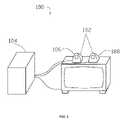
- FIG. 1shows a perspective view of an embodiment of the combined object capturing system and display device for capturing an object near a display device in accordance with one or more embodiments of the present disclosure
- FIG. 2shows a block diagram of the combined object capturing system and display device for capturing an object near a display device in accordance with one or more embodiments of the present disclosure
- FIG. 3shows an embodiment of the combined object capturing system and display device including a desktop computer in accordance with one or more embodiments of the present disclosure
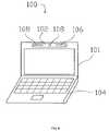
- FIG. 4shows an embodiment of the combined object capturing system and display device including a laptop computer in accordance with one or more embodiments of the present disclosure.
- the present disclosureincludes the combined object capturing system and display device for capturing images of an object near a display device. Certain embodiments of the present disclosure will now be discussed with reference to the aforementioned figures, wherein like reference numerals refer to like components.
- FIG. 1shows a perspective view of an embodiment of the combined object capturing system and display device 100 for capturing at least one image, scene or video of an object 111 positioned near the integrated object capturing system and display device 100 in accordance with one or more embodiments of the present disclosure.
- the combined object capturing system and display device 100may include an object capturing system 102 .
- the object capturing system 102is combined with or integrated with a display device 101 . While the object capturing system 102 will be referred to herein as being combined or integrated with the display device 101 , it is understood that the terms combined and integrated shall also refer to the object capturing system 102 being connected to or otherwise attached to the display device in a fixed or removable relationship or otherwise positioned alongside or adjacent to the display device 101 . In one or more embodiments, the object capturing system 102 positioned alongside or adjacent to the display device 101 is an integrated device.
- the object capturing system 102includes at least one projection device 106 that projects structured light 113 about a projection area 114 .
- the structured light 113may be projected onto a surface 110 of an object 111 near the display device 101 .
- the object capturing system 102further includes at least one detection device 108 , wherein the at least one of the detection devices 108 captures at least one image of the structured light 113 acting on a surface 110 of the object 111 .
- the detection device 108may include a field of view 118 that encompasses a portion of the surface 110 of the object 111 . It will be described herein that the object capturing system 102 captures images of the object 111 , where it is understood that such image capturing may include any number of captured images or a video or scene of the object 111 .
- a computing device 104is connected to the projection device 106 and the detection device 108 such that the computing device 104 may analyze the images captured by the detection device 108 to perform desired calculations such as, but not limited to, the 3D shape of the surface 110 of the object 111 , the distance to the object 111 , the orientation of the surface 110 being captured, 2D images of the surface 110 of the object 111 , and recognition of the object 111 .
- the computing device 104may also control the projection device 106 and/or the detection device 108 and the respective components of each.
- the computing device 104may be integrated with the object capturing system 102 . In one or more embodiments, the computing device 104 may be separate from the object capturing system 102 .
- the display device 101may be any device that displays information to a user or toward the object 111 .
- the display device 101may include, but is not limited to, a computer monitor, an LCD, a desktop computer, a laptop computer, a television, a portable or mobile telephone, a personal digital assistant, a handheld computing device, a remote terminal, or any other type of display or device that may include a display.
- At least one component of the object capturing system 102may be fixably or removably attached or integrated into the display device 101 .
- the projection device 106 and the detection device 108 of the object capturing unit 102may each be fixably or removably attached to or integrated into the display device 101 .
- at least one component of the object capturing system 102may be positioned alongside or adjacent to the display device 101 .
- the position and/or orientation of the object 111 with respect to the object capturing system 100may be determined based on the position and orientation of the object 111 with respect to the display device 101 .
- the display device 101may provide a reference position and/or a reference orientation for the position and orientation of object 111 .
- an object 111may be positioned adjacent to a display portion or screen of the display device 101 and oriented such that the surface 110 to be analyzed by the object capturing system 102 is directed toward the display portion of the display device 101 .
- the object capturing system 102may analyze the surface 110 of the object 111 .
- the object capturing system 102may base its calculations on the assumption that the object 111 is disposed at a reference position and/or in the reference orientation.
- the computing device 104may be combined or integrated with the display device 101 . In one or more embodiments, the computing device 104 may be separate from the display device 101 . In one or more embodiments, the computing device 104 interacts with the display device 101 such that the computing device 104 causes the display device 101 to provide an image. In one or more computing device 104 .
- the computing device 104 of object capturing system 100may include a general-purpose computer system which is suitable for implementing the methods for the 3D and 2D measurements of the shape of material objects in accordance with the present disclosure.
- the computing system 104is only one example of a suitable computing environment and is not intended to suggest any limitation as to the scope of use or functionality of the invention.
- the present system and method for combined object capturing system and display device 100is operational with numerous other general purpose or special purpose computing system environments or configurations.
- Examples of well known computing systems, environments, and/or configurationsthat may be suitable for use with the invention include, but are not limited to, personal computers, server computers, hand-held or laptop devices, multiprocessor systems, microprocessor-based systems, programmable consumer electronics, networked PCs, minicomputers, mainframe computers, distributed computing environments that include any of the above systems or devices, and the like.
- the analysis performed by the computing system 104 by algorithms and methodsmay be described in the general context of computer-executable instructions, such as program modules being executed by a computer.
- program modulesinclude routines, programs, objects, components, data structures, etc. that perform particular tasks or implement particular abstract data types.
- These algorithms and methodsmay also be practiced in distributed computing environments where tasks are performed by remote processing devices that are linked through a communications network.
- program modulesmay be located in both local and remote computer storage media including memory storage devices.
- the computing system 104may analyze the image captured by the detection device 108 by executing one or more computer programs.
- the computer programsmay be stored in a memory medium or storage medium such as a memory and/or ROM, or they may be provided to a CPU through a network connection or other I/O connection.
- While a computer or a computing devicewill be referred to herein as being connected to or associated with the display device 101 , it is understood that the terms computer and computing device shall also refer to the computing system 104 or otherwise to another device connected to or associated with the display device 101 .
- the object 111may be any material object capable of being captured with the object capturing system 102 , including, but not limited to, a face of a user of the display device 101 , a body part (e.g., a hand, palm, fingerprint, etc.) of a user of the display device 101 , an capturing badge, and any other object that can be identified by the combined object capturing system and display device 100 .
- the reference position and/or the reference orientation provided by the display device 101may correspond to a position and/or an orientation associated with the use of the display device 101 .
- the reference position and/or the reference orientation provided by the display device 101may be the position and/or the orientation at which the user would maintain its face during operation of the display device 101 .
- the object 111may be captured by the object capturing system 102 and then the captured images may be used for identification purposes based upon historical operation of the combined object capturing system and display device 100 .
- the historical operationmay include a setup phase of the object capturing system 102 , wherein the projection device 106 projects the structured light 113 on the object 111 , the detection devices 108 captures images of the surface 110 of the object 111 , and the computing device 104 analyzes the captured image. A measurement based on a result of the historical operation of the object 111 may be recorded.
- a measurement of the subsequent operation generated by the computing system 104may be compared to the measurement of the historical operation. If the measurement of subsequent operation corresponds to the measurement of the historical operation, then the object 111 is identified as the historical object; otherwise, the object 111 is identified as an object other than the historical object.
- the measurement results used in the setup phasemay be obtained from an external source and input into the combined object capturing system and display device 100 .
- the object capturing system 102may be capable of interfacing with the display device 101 such that a measurement made during an operation of the combined object capturing system and display device 100 may cause the display device 101 to perform a function of the display device 101 .
- the object capturing system 102may be capable of interfacing with the display device 101 such that a level of access to the display device 101 or the computing device 104 or another device connected to the display device 101 or computing device 104 may be provided based upon a measurement made during an operation of the object capturing system 102 .
- an object 111may be identified as a historical object, the object 111 may be granted a level of access to the display device 101 or another device, wherein the level of access is associated with the historical object.
- the level of access associated with the historical objectmay be determined during a setup phase of the object capturing system 102 .
- the face of a usercould be analyzed such that a user would be provided with secure access to the computing system 104 and/or use of the display device 101 through recognition of certain characteristics of the user captured by the object capturing system 102 .
- the level of access to the display device 101may determine at least one of: an image that may be displayed on the display device 101 ; access to or use of a function that the user may execute on the display device 101 or the computing device 104 or any other device connected to the display device 101 or the computing device 104 ; and a function that may be automatically displayed by the display device 101 or executed by the computing device 104 .
- the usermay not execute certain functions of the display device 101 or the computing device 104 if the object 111 is not identified as the historical object associated with a level of access necessary to execute such functions.
- the measurements described hereinmay be processed constantly.
- FIG. 2shows a block diagram of the combined object capturing system and display device 100 for capturing an object 111 near the display device 101 in accordance with one or more embodiments of the present disclosure.
- the combined object capturing system and display device 100may include at least one projection device 106 and at least one detection device 108 .
- the projection device 106is a slide projector including a light source 126 and a light modulating device 122 for modulating the light emitted from the light source 126 .
- the light modulating device 122may be a slide-type including a slide, a liquid crystal display (LCD)-type including a liquid crystal screen, or other device for creating a structured light 113 .
- LCDliquid crystal display
- the projection device 106may include a lens 181 having a vertex 124 for projecting a slide image as structured light 113 about a projection area 114 onto a surface 110 of an object 111 near the display device 101 .
- the structured light 113can also be generated using other methods, such as interferential, moir and diffractive light generation methods.
- the projection device 106projects the structured light 113 in a wavelength selected from one of optical, visible and infrared wavelengths. In at least one embodiment, the projection device 106 is a continuous light source. In at least one embodiment, the projection device 106 is incorporated in the display device 101 itself, wherein the display device 101 projects the structured light 113 .
- the detection device 108may include a photographic lens 180 having a vertex 130 , a matrix radiation receiver 128 and a driver 132 .
- the photographic lens 180forms an image on the surface of the matrix radiation receiver 128 .
- the driver 132functions as an electronic signal management and processing unit which controls operation of the matrix radiation receiver 128 and may convert the image captured by the matrix radiation receiver 128 to another format (e.g., VGA, bmp, jpeg, etc.) as desired or required before the captured image is transferred to a computing device 104 .
- the detection device 108may include a field of view 118 that encompasses a portion of the surface 110 of the object 111 .
- the projection device 106may include a projector axis 112
- the detection device 108may include a detector axis 116 , such that a triangulation angle 120 is the angle between the projector axis 112 and the detector axis 116 .
- the combined object capturing system and display device 100may include a display device 101 that comprises a display or monitor for a desktop computer 104 .
- FIG. 4shows an embodiment of the combined object capturing system and display device 100 in which the display device 101 is a component of a laptop computer 104 in accordance with one or more embodiments of the present disclosure.
Landscapes
- Engineering & Computer Science (AREA)
- Computer Vision & Pattern Recognition (AREA)
- Physics & Mathematics (AREA)
- General Physics & Mathematics (AREA)
- Length Measuring Devices By Optical Means (AREA)
- User Interface Of Digital Computer (AREA)
- Image Processing (AREA)
- Controls And Circuits For Display Device (AREA)
- Cash Registers Or Receiving Machines (AREA)
Abstract
Description
Claims (18)
Priority Applications (14)
| Application Number | Priority Date | Filing Date | Title |
|---|---|---|---|
| US11/868,352US8488129B2 (en) | 2007-10-05 | 2007-10-05 | Combined object capturing system and display device and associated method |
| JP2010528136AJP2010540970A (en) | 2007-10-05 | 2008-10-02 | Integrated object capturing system, display device, and related method |
| PL08836503TPL2208186T3 (en) | 2007-10-05 | 2008-10-02 | Combined object capturing system and display device and associated method |
| RU2010117657/08ARU2502136C2 (en) | 2007-10-05 | 2008-10-02 | Combined object capturing system and display device and associated method |
| EP08836503.6AEP2208186B8 (en) | 2007-10-05 | 2008-10-02 | Combined object capturing system and display device and associated method |
| MX2010003691AMX2010003691A (en) | 2007-10-05 | 2008-10-02 | Combined object capturing system and display device and associated method. |
| AU2008308677AAU2008308677A1 (en) | 2007-10-05 | 2008-10-02 | Combined object capturing system and display device and associated method |
| KR1020107009979AKR20100074254A (en) | 2007-10-05 | 2008-10-02 | Combined object capturing system and display device and associated method |
| CN2008801192675ACN102027317B (en) | 2007-10-05 | 2008-10-02 | Combined object capturing system and display device and associated method |
| ES08836503TES2824825T3 (en) | 2007-10-05 | 2008-10-02 | Combined object capture system and display device and associated method |
| PCT/US2008/078623WO2009046218A2 (en) | 2007-10-05 | 2008-10-02 | Combined object capturing system and display device and associated method |
| AU2012238301AAU2012238301A1 (en) | 2007-10-05 | 2012-10-10 | Combined object capturing system and display device and associated method |
| JP2013268323AJP2014089203A (en) | 2007-10-05 | 2013-12-26 | Combined object capturing system, display device, and associated method |
| AU2016277593AAU2016277593B2 (en) | 2007-10-05 | 2016-12-20 | Combined object capturing system and display device and associated method |
Applications Claiming Priority (1)
| Application Number | Priority Date | Filing Date | Title |
|---|---|---|---|
| US11/868,352US8488129B2 (en) | 2007-10-05 | 2007-10-05 | Combined object capturing system and display device and associated method |
Publications (2)
| Publication Number | Publication Date |
|---|---|
| US20090091581A1 US20090091581A1 (en) | 2009-04-09 |
| US8488129B2true US8488129B2 (en) | 2013-07-16 |
Family
ID=40522882
Family Applications (1)
| Application Number | Title | Priority Date | Filing Date |
|---|---|---|---|
| US11/868,352Active2031-03-05US8488129B2 (en) | 2007-10-05 | 2007-10-05 | Combined object capturing system and display device and associated method |
Country Status (11)
| Country | Link |
|---|---|
| US (1) | US8488129B2 (en) |
| EP (1) | EP2208186B8 (en) |
| JP (2) | JP2010540970A (en) |
| KR (1) | KR20100074254A (en) |
| CN (1) | CN102027317B (en) |
| AU (3) | AU2008308677A1 (en) |
| ES (1) | ES2824825T3 (en) |
| MX (1) | MX2010003691A (en) |
| PL (1) | PL2208186T3 (en) |
| RU (1) | RU2502136C2 (en) |
| WO (1) | WO2009046218A2 (en) |
Cited By (2)
| Publication number | Priority date | Publication date | Assignee | Title |
|---|---|---|---|---|
| US10565718B2 (en) | 2018-04-18 | 2020-02-18 | Faro Technologies, Inc. | System and method of scanning an environment |
| US10736757B2 (en) | 2017-01-13 | 2020-08-11 | Adapttech Limited | Fitting system |
Families Citing this family (19)
| Publication number | Priority date | Publication date | Assignee | Title |
|---|---|---|---|---|
| KR20080064155A (en) | 2005-10-14 | 2008-07-08 | 어플라이드 리써치 어쏘시에이츠 뉴질랜드 리미티드 | Method and apparatus for monitoring surface features |
| US8427424B2 (en) | 2008-09-30 | 2013-04-23 | Microsoft Corporation | Using physical objects in conjunction with an interactive surface |
| US8730309B2 (en) | 2010-02-23 | 2014-05-20 | Microsoft Corporation | Projectors and depth cameras for deviceless augmented reality and interaction |
| US9329469B2 (en) | 2011-02-17 | 2016-05-03 | Microsoft Technology Licensing, Llc | Providing an interactive experience using a 3D depth camera and a 3D projector |
| US9480907B2 (en) | 2011-03-02 | 2016-11-01 | Microsoft Technology Licensing, Llc | Immersive display with peripheral illusions |
| US20120223885A1 (en)* | 2011-03-02 | 2012-09-06 | Microsoft Corporation | Immersive display experience |
| US9597587B2 (en) | 2011-06-08 | 2017-03-21 | Microsoft Technology Licensing, Llc | Locational node device |
| KR101268515B1 (en)* | 2011-07-22 | 2013-06-04 | 경북대학교 산학협력단 | 3-dimensional scanner and method of reconstructing 3-dimensional image |
| US9179844B2 (en) | 2011-11-28 | 2015-11-10 | Aranz Healthcare Limited | Handheld skin measuring or monitoring device |
| CN104541126A (en)* | 2012-06-26 | 2015-04-22 | 西门子公司 | Device for mobile pattern projection and its application |
| US10979249B1 (en)* | 2014-03-02 | 2021-04-13 | Twitter, Inc. | Event-based content presentation using a social media platform |
| JP6516453B2 (en)* | 2014-11-26 | 2019-05-22 | 株式会社ミツトヨ | Image measuring device and measuring device |
| DK3436773T3 (en) | 2016-04-01 | 2021-07-12 | Lego As | Toy scanner |
| US10013527B2 (en) | 2016-05-02 | 2018-07-03 | Aranz Healthcare Limited | Automatically assessing an anatomical surface feature and securely managing information related to the same |
| US11116407B2 (en) | 2016-11-17 | 2021-09-14 | Aranz Healthcare Limited | Anatomical surface assessment methods, devices and systems |
| WO2018185560A2 (en) | 2017-04-04 | 2018-10-11 | Aranz Healthcare Limited | Anatomical surface assessment methods, devices and systems |
| WO2019012534A1 (en)* | 2017-07-12 | 2019-01-17 | Guardian Optical Technologies Ltd. | Visual, depth and micro-vibration data extraction using a unified imaging device |
| KR102668245B1 (en)* | 2018-10-29 | 2024-05-23 | 삼성전자주식회사 | Apparatus and method for measuring depth of three dimensions |
| WO2020234653A1 (en) | 2019-05-20 | 2020-11-26 | Aranz Healthcare Limited | Automated or partially automated anatomical surface assessment methods, devices and systems |
Citations (16)
| Publication number | Priority date | Publication date | Assignee | Title |
|---|---|---|---|---|
| US6064759A (en)* | 1996-11-08 | 2000-05-16 | Buckley; B. Shawn | Computer aided inspection machine |
| US6252623B1 (en) | 1998-05-15 | 2001-06-26 | 3Dmetrics, Incorporated | Three dimensional imaging system |
| US6341016B1 (en) | 1999-08-06 | 2002-01-22 | Michael Malione | Method and apparatus for measuring three-dimensional shape of object |
| US6493095B1 (en) | 1999-04-13 | 2002-12-10 | Inspeck Inc. | Optional 3D digitizer, system and method for digitizing an object |
| US20030112447A1 (en)* | 2001-12-19 | 2003-06-19 | General Electric Company | Method and device for reduction in noise in images from shiny parts |
| US20040105580A1 (en) | 2002-11-22 | 2004-06-03 | Hager Gregory D. | Acquisition of three-dimensional images by an active stereo technique using locally unique patterns |
| US20050195383A1 (en)* | 1994-05-23 | 2005-09-08 | Breed David S. | Method for obtaining information about objects in a vehicular blind spot |
| US20060039600A1 (en)* | 2004-08-19 | 2006-02-23 | Solem Jan E | 3D object recognition |
| US20060044546A1 (en)* | 2002-11-11 | 2006-03-02 | Qinetiq Limited | Ranging apparatus |
| US20060103853A1 (en)* | 2004-11-12 | 2006-05-18 | The Boeing Company | Optical projection system |
| US20060132803A1 (en)* | 2004-12-17 | 2006-06-22 | The Boeing Company | Method and apparatus for combining a targetless optical measurement function and optical projection of information |
| US20060206724A1 (en)* | 2005-02-16 | 2006-09-14 | David Schaufele | Biometric-based systems and methods for identity verification |
| US20080106746A1 (en)* | 2005-10-11 | 2008-05-08 | Alexander Shpunt | Depth-varying light fields for three dimensional sensing |
| US20080172261A1 (en)* | 2007-01-12 | 2008-07-17 | Jacob C Albertson | Adjusting a consumer experience based on a 3d captured image stream of a consumer response |
| US7612869B2 (en)* | 1998-02-25 | 2009-11-03 | California Institute Of Technology | Aperture coded camera for three dimensional imaging |
| US7774075B2 (en)* | 2002-11-06 | 2010-08-10 | Lin Julius J Y | Audio-visual three-dimensional input/output |
Family Cites Families (15)
| Publication number | Priority date | Publication date | Assignee | Title |
|---|---|---|---|---|
| US4449189A (en)* | 1981-11-20 | 1984-05-15 | Siemens Corporation | Personal access control system using speech and face recognition |
| DE4324849C2 (en)* | 1993-07-23 | 1995-07-13 | Schneider Rundfunkwerke Ag | Video system for generating a color video image on a screen |
| DE19712844A1 (en)* | 1997-03-26 | 1998-10-08 | Siemens Ag | Method for three-dimensional identification of objects |
| JP2001012922A (en)* | 1999-06-29 | 2001-01-19 | Minolta Co Ltd | Three-dimensional data-processing device |
| CN1304114A (en)* | 1999-12-13 | 2001-07-18 | 中国科学院自动化研究所 | Identity identification method based on multiple biological characteristics |
| JP2001204047A (en)* | 2000-01-21 | 2001-07-27 | Minolta Co Ltd | Three-dimensional input device |
| CA2306515A1 (en)* | 2000-04-25 | 2001-10-25 | Inspeck Inc. | Internet stereo vision, 3d digitizing, and motion capture camera |
| EP1681613B1 (en)* | 2000-10-13 | 2009-11-11 | LG Electronics Inc. | Apparatus for automatically adjusting angle of image device for information processing equipment |
| US7248716B2 (en)* | 2001-07-06 | 2007-07-24 | Palantyr Research, Llc | Imaging system, methodology, and applications employing reciprocal space optical design |
| JP2003270719A (en)* | 2002-03-13 | 2003-09-25 | Osaka Industrial Promotion Organization | Projection method, projector, and method and system for supporting work |
| JP2004318823A (en)* | 2003-03-28 | 2004-11-11 | Seiko Epson Corp | Information display system, information processing device, pointing device, and pointer mark display method in information display system |
| JP2007048232A (en)* | 2005-08-12 | 2007-02-22 | Fuji Xerox Co Ltd | Information processing device, information processing method, and computer program |
| JP4826234B2 (en)* | 2005-11-30 | 2011-11-30 | オムロン株式会社 | Face authentication apparatus, security strength changing method and program |
| CN101501442B (en)* | 2006-03-14 | 2014-03-19 | 普莱姆传感有限公司 | Depth-varying light field for 3D sensing |
| JP2007256116A (en)* | 2006-03-23 | 2007-10-04 | Brother Ind Ltd | Three-dimensional shape detector |
- 2007
- 2007-10-05USUS11/868,352patent/US8488129B2/enactiveActive
- 2008
- 2008-10-02AUAU2008308677Apatent/AU2008308677A1/ennot_activeAbandoned
- 2008-10-02WOPCT/US2008/078623patent/WO2009046218A2/enactiveApplication Filing
- 2008-10-02CNCN2008801192675Apatent/CN102027317B/enactiveActive
- 2008-10-02MXMX2010003691Apatent/MX2010003691A/enactiveIP Right Grant
- 2008-10-02RURU2010117657/08Apatent/RU2502136C2/enactive
- 2008-10-02PLPL08836503Tpatent/PL2208186T3/enunknown
- 2008-10-02EPEP08836503.6Apatent/EP2208186B8/enactiveActive
- 2008-10-02JPJP2010528136Apatent/JP2010540970A/enactivePending
- 2008-10-02KRKR1020107009979Apatent/KR20100074254A/ennot_activeCeased
- 2008-10-02ESES08836503Tpatent/ES2824825T3/enactiveActive
- 2012
- 2012-10-10AUAU2012238301Apatent/AU2012238301A1/ennot_activeAbandoned
- 2013
- 2013-12-26JPJP2013268323Apatent/JP2014089203A/ennot_activeWithdrawn
- 2016
- 2016-12-20AUAU2016277593Apatent/AU2016277593B2/enactiveActive
Patent Citations (16)
| Publication number | Priority date | Publication date | Assignee | Title |
|---|---|---|---|---|
| US20050195383A1 (en)* | 1994-05-23 | 2005-09-08 | Breed David S. | Method for obtaining information about objects in a vehicular blind spot |
| US6064759A (en)* | 1996-11-08 | 2000-05-16 | Buckley; B. Shawn | Computer aided inspection machine |
| US7612869B2 (en)* | 1998-02-25 | 2009-11-03 | California Institute Of Technology | Aperture coded camera for three dimensional imaging |
| US6252623B1 (en) | 1998-05-15 | 2001-06-26 | 3Dmetrics, Incorporated | Three dimensional imaging system |
| US6493095B1 (en) | 1999-04-13 | 2002-12-10 | Inspeck Inc. | Optional 3D digitizer, system and method for digitizing an object |
| US6341016B1 (en) | 1999-08-06 | 2002-01-22 | Michael Malione | Method and apparatus for measuring three-dimensional shape of object |
| US20030112447A1 (en)* | 2001-12-19 | 2003-06-19 | General Electric Company | Method and device for reduction in noise in images from shiny parts |
| US7774075B2 (en)* | 2002-11-06 | 2010-08-10 | Lin Julius J Y | Audio-visual three-dimensional input/output |
| US20060044546A1 (en)* | 2002-11-11 | 2006-03-02 | Qinetiq Limited | Ranging apparatus |
| US20040105580A1 (en) | 2002-11-22 | 2004-06-03 | Hager Gregory D. | Acquisition of three-dimensional images by an active stereo technique using locally unique patterns |
| US20060039600A1 (en)* | 2004-08-19 | 2006-02-23 | Solem Jan E | 3D object recognition |
| US20060103853A1 (en)* | 2004-11-12 | 2006-05-18 | The Boeing Company | Optical projection system |
| US20060132803A1 (en)* | 2004-12-17 | 2006-06-22 | The Boeing Company | Method and apparatus for combining a targetless optical measurement function and optical projection of information |
| US20060206724A1 (en)* | 2005-02-16 | 2006-09-14 | David Schaufele | Biometric-based systems and methods for identity verification |
| US20080106746A1 (en)* | 2005-10-11 | 2008-05-08 | Alexander Shpunt | Depth-varying light fields for three dimensional sensing |
| US20080172261A1 (en)* | 2007-01-12 | 2008-07-17 | Jacob C Albertson | Adjusting a consumer experience based on a 3d captured image stream of a consumer response |
Non-Patent Citations (2)
| Title |
|---|
| Form PCT/ISA/210 in connection with International Application No. PCT/US2008/078623; filed Oct. 2, 2008 (Artec Group, Inc. et al.) 3 pgs. |
| Form PCT/ISA/237 in connection with International Application No. PCT/US2008/078623; filed Oct. 2, 2008 (Artec Group, Inc. et al.) 4 pgs. |
Cited By (4)
| Publication number | Priority date | Publication date | Assignee | Title |
|---|---|---|---|---|
| US10736757B2 (en) | 2017-01-13 | 2020-08-11 | Adapttech Limited | Fitting system |
| US10565718B2 (en) | 2018-04-18 | 2020-02-18 | Faro Technologies, Inc. | System and method of scanning an environment |
| US10896517B2 (en) | 2018-04-18 | 2021-01-19 | Faro Technologies, Inc. | System and method of scanning an environment |
| US11016196B2 (en) | 2018-04-18 | 2021-05-25 | Faro Technologies, Inc. | System and method of scanning an environment |
Also Published As
| Publication number | Publication date |
|---|---|
| AU2016277593B2 (en) | 2018-08-09 |
| RU2502136C2 (en) | 2013-12-20 |
| ES2824825T3 (en) | 2021-05-13 |
| US20090091581A1 (en) | 2009-04-09 |
| JP2010540970A (en) | 2010-12-24 |
| CN102027317A (en) | 2011-04-20 |
| WO2009046218A2 (en) | 2009-04-09 |
| WO2009046218A3 (en) | 2009-05-22 |
| EP2208186B1 (en) | 2020-07-22 |
| CN102027317B (en) | 2013-05-01 |
| EP2208186B8 (en) | 2020-09-02 |
| AU2012238301A1 (en) | 2012-11-01 |
| EP2208186A4 (en) | 2016-05-11 |
| AU2016277593A1 (en) | 2017-01-12 |
| PL2208186T3 (en) | 2021-02-08 |
| JP2014089203A (en) | 2014-05-15 |
| RU2010117657A (en) | 2011-11-10 |
| AU2008308677A1 (en) | 2009-04-09 |
| KR20100074254A (en) | 2010-07-01 |
| EP2208186A2 (en) | 2010-07-21 |
| MX2010003691A (en) | 2010-08-03 |
Similar Documents
| Publication | Publication Date | Title |
|---|---|---|
| US8488129B2 (en) | Combined object capturing system and display device and associated method | |
| KR101601331B1 (en) | System and method for three-dimensional measurment of the shape of material object | |
| US8170297B2 (en) | Face authentication system and face authentication method | |
| US20080267454A1 (en) | Measurement apparatus and control method | |
| US20040008259A1 (en) | Optical methods for remotely measuring objects | |
| US9025067B2 (en) | Apparatus and method for image super-resolution using integral shifting optics | |
| US20150369593A1 (en) | Orthographic image capture system | |
| EP3371779B1 (en) | Systems and methods for forming models of three dimensional objects | |
| CN107493428A (en) | Shooting control method and device | |
| CN116438467A (en) | Depth measurement by display | |
| US20170186170A1 (en) | Facial contour recognition for identification | |
| US10403002B2 (en) | Method and system for transforming between physical images and virtual images | |
| HK1146501B (en) | Combined object capturing system and display device and associated method | |
| HK1146501A (en) | Combined object capturing system and display device and associated method | |
| US9842402B1 (en) | Detecting foreground regions in panoramic video frames | |
| Cai et al. | A new method of detecting fingertip touch for the projector-camera HCI system | |
| CN107623823B (en) | Video communication background display method and device | |
| HK1148064B (en) | System and method for three-dimensional measurement of the shape of material objects | |
| HK1148064A (en) | System and method for three-dimensional measurement of the shape of material objects | |
| HK1208902A1 (en) | Portable three-dimensional metrology with data displayed on the measured surface |
Legal Events
| Date | Code | Title | Description |
|---|---|---|---|
| AS | Assignment | Owner name:ARTEC VENTURES, RUSSIAN FEDERATION Free format text:ASSIGNMENT OF ASSIGNORS INTEREST;ASSIGNOR:LAPA, YAN N.;REEL/FRAME:019927/0204 Effective date:20071005 | |
| AS | Assignment | Owner name:ARTEC GROUP, INC., CALIFORNIA Free format text:ASSIGNMENT OF ASSIGNORS INTEREST;ASSIGNOR:ARTEC VENTURES, A CORPORATION;REEL/FRAME:021437/0698 Effective date:20080822 | |
| STCF | Information on status: patent grant | Free format text:PATENTED CASE | |
| AS | Assignment | Owner name:ARTEC EUROPE, S.A.R.L., LUXEMBOURG Free format text:ASSIGNMENT OF ASSIGNORS INTEREST;ASSIGNOR:ARTEC GROUP INC.;REEL/FRAME:037240/0823 Effective date:20140401 | |
| FPAY | Fee payment | Year of fee payment:4 | |
| MAFP | Maintenance fee payment | Free format text:PAYMENT OF MAINTENANCE FEE, 8TH YR, SMALL ENTITY (ORIGINAL EVENT CODE: M2552); ENTITY STATUS OF PATENT OWNER: SMALL ENTITY Year of fee payment:8 | |
| MAFP | Maintenance fee payment | Free format text:PAYMENT OF MAINTENANCE FEE, 12TH YR, SMALL ENTITY (ORIGINAL EVENT CODE: M2553); ENTITY STATUS OF PATENT OWNER: SMALL ENTITY Year of fee payment:12 |