US8487686B2 - Active guarding for reduction of resistive and capacitive signal loading with adjustable control of compensation level - Google Patents
Active guarding for reduction of resistive and capacitive signal loading with adjustable control of compensation levelDownload PDFInfo
- Publication number
- US8487686B2 US8487686B2US12/594,075US59407508AUS8487686B2US 8487686 B2US8487686 B2US 8487686B2US 59407508 AUS59407508 AUS 59407508AUS 8487686 B2US8487686 B2US 8487686B2
- Authority
- US
- United States
- Prior art keywords
- impedance
- signal
- parasitic
- gain
- transmission channel
- Prior art date
- Legal status (The legal status is an assumption and is not a legal conclusion. Google has not performed a legal analysis and makes no representation as to the accuracy of the status listed.)
- Expired - Fee Related, expires
Links
Images


Classifications
- H—ELECTRICITY
- H03—ELECTRONIC CIRCUITRY
- H03F—AMPLIFIERS
- H03F1/00—Details of amplifiers with only discharge tubes, only semiconductor devices or only unspecified devices as amplifying elements
- H03F1/56—Modifications of input or output impedances, not otherwise provided for
- H—ELECTRICITY
- H03—ELECTRONIC CIRCUITRY
- H03F—AMPLIFIERS
- H03F1/00—Details of amplifiers with only discharge tubes, only semiconductor devices or only unspecified devices as amplifying elements
- H03F1/08—Modifications of amplifiers to reduce detrimental influences of internal impedances of amplifying elements
- H03F1/14—Modifications of amplifiers to reduce detrimental influences of internal impedances of amplifying elements by use of neutralising means
Definitions
- Applicants' teachingsare related to a method and circuit for reducing resistive and capacitive signal loading.
- I compV signal ⁇ ( G - 1 ) ⁇ ( 1 Z comp ) Equation ⁇ ⁇ ( 2 )
- Circuit 500can also comprise compensation level portion 580 , when used in a configuration similar to FIG. 3 .
- Compensation level portion 580is in turn comprised of resistor 546 and capacitor 548 .
- Compensation level portion 580is used as the compensation impedance.
- gain control portion 530 and compensation level portion 582one may adjust the compensation current that is provided to the signal-transmission channel, and thereby match the compensation current magnitude to the magnitude of the leakage current. This may be done according to equation (3) given above. It should be understood however, that in various embodiments, where circuit 500 is used in a configuration similar to FIG. 4 , compensation level portion 580 and output 526 can be omitted.
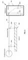
- Circuit 600comprises amplifier 610 , which is coupled to compensation impedance 680 . Both amplifier 610 and compensation impedance 680 are coupled to signal path 682 , which has parasitic impedance 684 .
- Parasitic capacitance 684may be comprised of various impedances such as capacitances 686 and 688 , which may be distributed throughout the signal-transmission channel 682 . Parasitic capacitances 686 and 688 have termination points 685 b .
- Both compensation impedance 680 and parasitic impedance 684are illustrated as only containing capacitances. However, it is not intended to exclude embodiments in which compensation impedance 680 and parasitic impedance 684 include resistances or a combination of capacitances and resistances, which may appear as some combination of parallel or serial connections.
- Amplifier 610comprises an operational amplifier 612 , with a non-inverting input 614 , an inverting input 616 , an output node 617 , and power rails 618 and 620 .
- Amplifier 610further comprises resistor 634 connected between the non-inverting input 614 and signal-transmission channel 682 .
- Resistor 636which is connected between ground 638 and inverting input 616 , as well as resistor 640 , form a gain control portion. In various embodiments, the values of resistors 636 and 640 are selected to have a gain with a value greater than 1.
- Capacitor 642 , resistor 644 and resistor 646form a stability control portion.
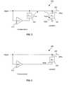
- Amplifier 710comprises an operational amplifier 712 , which may be, but is not limited to being, implemented as an U21 LMH6642 operation amplifier.
- Operational amplifier 712has a non-inverting input 714 , an inverting input 716 , an output node 717 , and power rails 718 and 720 .
- Amplifier 710further comprises resistor 734 connected between the inverting input 714 and signal-transmission channel 782 .
- Resistor 736has a value of 100 k ⁇ and is connected between ground 738 and inverting input 716 .
- Resistor 740has a value of 10 k ⁇ and is connected in parallel with capacitor 742 .
- Resistors 738 and 740form a gain control portion.
- Capacitor 742 and resistor 746form a stability control portion.
- Capacitor 742has a value of 10 pF, and resistor 746 has value of 100 ⁇ .
- Circuit 700may be utilized when the termination point of the parasitic impedance is not readily accessible. Specifically, it may not be possible to connect the output of amplifier 710 to terminal 785 b of parasitic impedance 784 .
- phase lead of an appropriate signalmay be added to the amplifier of any of the above signals. This requires that the circuit be able to predict the future values of the signal. In the case of sinusoidal signals, or any other periodic signal, this may be accomplished very easily as the value of such a signal may always be predicted for any future time.
- FIG. 9is a schematic diagram of a circuit 900 according to various embodiments of applicants' teachings. Specifically, FIG. 9 , illustrates the application of active guarding circuits according to applicants' teachings to a circuit similar to that illustrated in FIG. 2 .
Landscapes
- Engineering & Computer Science (AREA)
- Power Engineering (AREA)
- Amplifiers (AREA)
- Networks Using Active Elements (AREA)
Abstract
Description
Icomp=Ileakage
Claims (22)
Priority Applications (1)
| Application Number | Priority Date | Filing Date | Title |
|---|---|---|---|
| US12/594,075US8487686B2 (en) | 2007-03-30 | 2008-03-31 | Active guarding for reduction of resistive and capacitive signal loading with adjustable control of compensation level |
Applications Claiming Priority (3)
| Application Number | Priority Date | Filing Date | Title |
|---|---|---|---|
| US90920607P | 2007-03-30 | 2007-03-30 | |
| US12/594,075US8487686B2 (en) | 2007-03-30 | 2008-03-31 | Active guarding for reduction of resistive and capacitive signal loading with adjustable control of compensation level |
| PCT/CA2008/000588WO2008119166A1 (en) | 2007-03-30 | 2008-03-31 | Active guarding for reduction of resistive and capactive signal loading with adjustable control of compensation level |
Publications (2)
| Publication Number | Publication Date |
|---|---|
| US20100109739A1 US20100109739A1 (en) | 2010-05-06 |
| US8487686B2true US8487686B2 (en) | 2013-07-16 |
Family
ID=39807749
Family Applications (1)
| Application Number | Title | Priority Date | Filing Date |
|---|---|---|---|
| US12/594,075Expired - Fee RelatedUS8487686B2 (en) | 2007-03-30 | 2008-03-31 | Active guarding for reduction of resistive and capacitive signal loading with adjustable control of compensation level |
Country Status (7)
| Country | Link |
|---|---|
| US (1) | US8487686B2 (en) |
| EP (1) | EP2137589B1 (en) |
| JP (1) | JP5101685B2 (en) |
| AU (1) | AU2008234370B2 (en) |
| CA (1) | CA2703361C (en) |
| ES (1) | ES2537077T3 (en) |
| WO (1) | WO2008119166A1 (en) |
Cited By (1)
| Publication number | Priority date | Publication date | Assignee | Title |
|---|---|---|---|---|
| US20160015290A1 (en)* | 2014-07-17 | 2016-01-21 | Samsung Electronics Co., Ltd. | Method and apparatus for measuring bioimpedance |
Families Citing this family (15)
| Publication number | Priority date | Publication date | Assignee | Title |
|---|---|---|---|---|
| AUPQ113799A0 (en) | 1999-06-22 | 1999-07-15 | University Of Queensland, The | A method and device for measuring lymphoedema |
| US8744564B2 (en) | 2004-06-18 | 2014-06-03 | Impedimed Limited | Oedema detection |
| WO2006056074A1 (en) | 2004-11-26 | 2006-06-01 | Z-Tech (Canada) Inc. | Weighted gradient method and system for diagnosing disease |
| US20110054343A1 (en) | 2005-07-01 | 2011-03-03 | Impedimed Limited | Monitoring system |
| EP2460468A1 (en) | 2005-07-01 | 2012-06-06 | Impedimed Limited | Monitoring system |
| JP5208749B2 (en) | 2005-10-11 | 2013-06-12 | インペダイムド・リミテッド | Hydration status monitoring |
| AU2007266311B2 (en) | 2006-05-30 | 2014-01-30 | Impedimed Limited | Impedance measurements |
| AU2007327573B2 (en) | 2006-11-30 | 2013-07-18 | Impedimed Limited | Measurement apparatus |
| WO2008128281A1 (en) | 2007-04-20 | 2008-10-30 | Impedimed Limited | Monitoring system and probe |
| AU2008207672B2 (en) | 2008-02-15 | 2013-10-31 | Impedimed Limited | Impedance Analysis |
| US9615766B2 (en) | 2008-11-28 | 2017-04-11 | Impedimed Limited | Impedance measurement process |
| US9615767B2 (en) | 2009-10-26 | 2017-04-11 | Impedimed Limited | Fluid level indicator determination |
| CA2778770A1 (en)* | 2009-11-18 | 2011-05-26 | Chung Shing Fan | Signal distribution for patient-electrode measurements |
| GB2544920B (en)* | 2011-05-12 | 2018-02-07 | Thermo Fisher Scient (Bremen) Gmbh | Electrostatic ion trapping with shielding conductor |
| WO2015021339A1 (en)* | 2013-08-07 | 2015-02-12 | Xagenic Inc. | Potentiostat reference electrode interface |
Citations (217)
| Publication number | Priority date | Publication date | Assignee | Title |
|---|---|---|---|---|
| US3316896A (en) | 1962-10-18 | 1967-05-02 | Thomasset Auguste Louis | Apparatus and methods for the measure of the electrical impedance of living organisms |
| US3851641A (en) | 1973-11-29 | 1974-12-03 | J Toole | Method and apparatus for determining internal impedance of animal body part |
| US3871359A (en) | 1973-06-25 | 1975-03-18 | Interscience Technology Corp | Impedance measuring system |
| US4008712A (en) | 1975-11-14 | 1977-02-22 | J. M. Richards Laboratories | Method for monitoring body characteristics |
| US4034854A (en) | 1976-07-16 | 1977-07-12 | M I Systems, Inc. | Electrode package |
| US4144878A (en) | 1974-06-19 | 1979-03-20 | Wheeler H Brownell | Occlusive impedance phlebograph and method therefor |
| US4184486A (en) | 1977-08-11 | 1980-01-22 | Radelkis Elektrokemiai Muszergyarto Szovetkezet | Diagnostic method and sensor device for detecting lesions in body tissues |
| DE2912349A1 (en) | 1979-03-29 | 1980-10-16 | Liebisch Geb | Detector system for human skin moisture content - has scanning head with two contact electrodes attached to skin under specified pressure |
| US4291708A (en) | 1977-11-02 | 1981-09-29 | Yeda Research & Development Co. Ltd. | Apparatus and method for detection of tumors in tissue |
| FR2486386A1 (en) | 1980-07-09 | 1982-01-15 | Argamakoff Alexis | Thermographic and impedance measurer for cancer scanning - has single electrode or matrix supplying temp. and impedance signals |
| US4314563A (en) | 1970-09-24 | 1982-02-09 | The United States Of America As Represented By The Administrator Of The Veterans Administration | Apparatus for measuring relative changes in blood volume in a portion of an animal body to detect a venous occlusion |
| US4365634A (en) | 1979-12-06 | 1982-12-28 | C. R. Bard, Inc. | Medical electrode construction |
| US4407288A (en) | 1981-02-18 | 1983-10-04 | Mieczyslaw Mirowski | Implantable heart stimulator and stimulation method |
| US4407300A (en) | 1980-07-14 | 1983-10-04 | Davis Robert E | Potentiometric diagnosis of cancer in vivo |
| US4450527A (en) | 1982-06-29 | 1984-05-22 | Bomed Medical Mfg. Ltd. | Noninvasive continuous cardiac output monitor |
| US4458694A (en) | 1977-11-02 | 1984-07-10 | Yeda Research & Development Co., Ltd. | Apparatus and method for detection of tumors in tissue |
| US4468832A (en) | 1983-06-24 | 1984-09-04 | Libman Broom Company | Refill sponge mop assembly |
| US4486835A (en) | 1981-05-13 | 1984-12-04 | Yeda Research And Development Co. Ltd. | Apparatus and techniques for electric tomography |
| US4537203A (en) | 1980-10-21 | 1985-08-27 | Tokyo Shibaura Denki Kabushiki Kaisha | Abnormal cell detecting device |
| US4539640A (en) | 1982-01-12 | 1985-09-03 | Tasc Ltd. | Reconstruction system and methods for impedance imaging |
| US4557271A (en) | 1983-05-11 | 1985-12-10 | Stoller Kenneth P | Method and apparatus for detecting body illness, dysfunction, disease and/or pathology |
| GB2131558B (en) | 1982-11-05 | 1986-03-05 | Walter Farrer | Measuring potential difference |
| US4583549A (en) | 1984-05-30 | 1986-04-22 | Samir Manoli | ECG electrode pad |
| US4602338A (en) | 1982-09-02 | 1986-07-22 | British Telecommunications | Impedance measurement in 4-wire to 2-wire converters |
| US4617639A (en) | 1984-08-08 | 1986-10-14 | Caterpillar Industrial Inc. | Hour meter apparatus and method |
| US4646754A (en) | 1985-02-19 | 1987-03-03 | Seale Joseph B | Non-invasive determination of mechanical characteristics in the body |
| US4686477A (en) | 1985-09-30 | 1987-08-11 | Mobil Oil Corporation | Multiple frequency electric excitation method and identifying complex lithologies of subsurface formations |
| US4688580A (en) | 1985-07-11 | 1987-08-25 | The Johns Hopkins University | Non-invasive electromagnetic technique for monitoring bone healing and bone fracture localization |
| US4763660A (en) | 1985-12-10 | 1988-08-16 | Cherne Industries, Inc. | Flexible and disposable electrode belt device |
| US4793362A (en) | 1982-04-22 | 1988-12-27 | Karolinska Institutet | Method and apparatus for monitoring the fluid balance of the body |
| US4895163A (en) | 1988-05-24 | 1990-01-23 | Bio Analogics, Inc. | System for body impedance data acquisition |
| US4905705A (en) | 1989-03-03 | 1990-03-06 | Research Triangle Institute | Impedance cardiometer |
| US4911175A (en) | 1987-09-17 | 1990-03-27 | Diana Twyman | Method for measuring total body cell mass and total extracellular mass by bioelectrical resistance and reactance |
| US4942880A (en) | 1981-01-28 | 1990-07-24 | Ceske Vysoke Uceni Technicke V Praze | Method for non-invasive electric diagnosis and therapy in hemodialysis and general medicine |
| US4951682A (en) | 1988-06-22 | 1990-08-28 | The Cleveland Clinic Foundation | Continuous cardiac output by impedance measurements in the heart |
| US5025784A (en) | 1987-09-05 | 1991-06-25 | Harbin Polytechnic University | Apparatus and method for detecting and processing impedance rheogram |
| US5063937A (en) | 1990-09-12 | 1991-11-12 | Wright State University | Multiple frequency bio-impedance measurement system |
| EP0249823B1 (en) | 1986-06-16 | 1991-12-18 | Pacesetter AB | Device for the control of a heart pacer using impedance measurement at body tissues |
| US5143079A (en) | 1989-08-02 | 1992-09-01 | Yeda Research And Development Company Limited | Apparatus for detection of tumors in tissue |
| US5197479A (en) | 1991-05-13 | 1993-03-30 | Mortara Instrument | Automatic electrode channel impedance measurement system for egg monitor |
| US5246008A (en) | 1991-01-11 | 1993-09-21 | Guido Fehling | Method for monitoring a patient for rejection reactions to an implanted heart |
| US5280429A (en) | 1991-04-30 | 1994-01-18 | Xitron Technologies | Method and apparatus for displaying multi-frequency bio-impedance |
| US5305192A (en) | 1991-11-01 | 1994-04-19 | Linear Technology Corporation | Switching regulator circuit using magnetic flux-sensing |
| US5309917A (en) | 1991-09-12 | 1994-05-10 | Drexel University | System and method of impedance cardiography and heartbeat determination |
| US5311878A (en) | 1990-06-13 | 1994-05-17 | British Technology Group Limited | Real-time electrical impedance tomography system |
| US5372141A (en) | 1992-07-01 | 1994-12-13 | Body Composition Analyzers, Inc. | Body composition analyzer |
| US5415164A (en) | 1991-11-04 | 1995-05-16 | Biofield Corp. | Apparatus and method for screening and diagnosing trauma or disease in body tissues |
| US5421344A (en) | 1991-10-23 | 1995-06-06 | Max Reinhard | Method and means of determining the health condition of a living creature |
| GB2260416B (en) | 1991-10-10 | 1995-07-26 | Smiths Industries Plc | Resistance monitors |
| US5465730A (en) | 1991-07-26 | 1995-11-14 | British Technology Group Ltd. | Electrical impedance tomography |
| EP0357309B1 (en) | 1988-08-29 | 1995-11-22 | B.I. Incorporated | Personnel monitoring system |
| US5469859A (en) | 1992-06-24 | 1995-11-28 | N.I. Medical Ltd. | Non-invasive method and device for collecting measurements representing body activity and determining cardiorespiratory parameters of the human body based upon the measurements collected |
| US5503157A (en) | 1995-03-17 | 1996-04-02 | Sramek; Bohumir | System for detection of electrical bioimpedance signals |
| US5505209A (en) | 1994-07-07 | 1996-04-09 | Reining International, Ltd. | Impedance cardiograph apparatus and method |
| US5544662A (en) | 1991-07-09 | 1996-08-13 | Rensselaer Polytechnic Institute | High-speed electric tomography |
| US5557242A (en) | 1995-05-22 | 1996-09-17 | Motorola, Inc. | Method and apparatus for dielectric absorption compensation |
| US5588429A (en) | 1991-07-09 | 1996-12-31 | Rensselaer Polytechnic Institute | Process for producing optimal current patterns for electrical impedance tomography |
| US5596283A (en) | 1991-06-26 | 1997-01-21 | Digital Equipment Corporation | Continuous motion electrical circuit interconnect test method and apparatus |
| FR2748928A1 (en) | 1996-05-23 | 1997-11-28 | Jabourian Artin Pascal | Portable electronic cardiac rhythm detector |
| US5704355A (en) | 1994-07-01 | 1998-01-06 | Bridges; Jack E. | Non-invasive system for breast cancer detection |
| US5718231A (en) | 1993-06-15 | 1998-02-17 | British Technology Group Ltd. | Laser ultrasound probe and ablator |
| US5732710A (en) | 1996-08-09 | 1998-03-31 | R.S. Medical Monitoring Ltd. | Method and device for stable impedance plethysmography |
| US5746214A (en) | 1992-10-30 | 1998-05-05 | British Technology Group Limited | Investigation of a body |
| US5759159A (en) | 1996-09-25 | 1998-06-02 | Ormco Corporation | Method and apparatus for apical detection with complex impedance measurement |
| RU2112416C1 (en) | 1994-05-10 | 1998-06-10 | Научно-исследовательский институт вычислительной техники | Method for checking of tissue or organ condition after operation and device for its realization |
| US5788643A (en) | 1997-04-22 | 1998-08-04 | Zymed Medical Instrumentation, Inc. | Process for monitoring patients with chronic congestive heart failure |
| US5800350A (en) | 1993-11-01 | 1998-09-01 | Polartechnics, Limited | Apparatus for tissue type recognition |
| US5807251A (en) | 1994-03-11 | 1998-09-15 | British Technology Group Limited | Electrical impedance tomography |
| US5807272A (en) | 1995-10-31 | 1998-09-15 | Worcester Polytechnic Institute | Impedance spectroscopy system for ischemia monitoring and detection |
| US5807270A (en) | 1994-06-20 | 1998-09-15 | Williams; Christopher Edward | Brain damage monitor |
| US5810742A (en) | 1994-10-24 | 1998-09-22 | Transcan Research & Development Co., Ltd. | Tissue characterization based on impedance images and on impedance measurements |
| US5919142A (en) | 1995-06-22 | 1999-07-06 | Btg International Limited | Electrical impedance tomography method and apparatus |
| US6011992A (en) | 1996-05-09 | 2000-01-04 | Church Of Spirtual Technology | System for measuring and indicating changes in the resistance of a living body |
| US6015389A (en) | 1995-12-06 | 2000-01-18 | Btg International Limited | Impedance pneumography |
| US6018677A (en) | 1997-11-25 | 2000-01-25 | Tectrix Fitness Equipment, Inc. | Heart rate monitor and method |
| JP2000107138A (en) | 1998-10-01 | 2000-04-18 | Denso Corp | Health management apparatus |
| JP2000139867A (en) | 1998-11-10 | 2000-05-23 | Sekisui Chem Co Ltd | Body composition estimation method, body composition estimation apparatus and recording medium recording body composition estimation program |
| US6122544A (en) | 1998-05-01 | 2000-09-19 | Organ; Leslie William | Electrical impedance method and apparatus for detecting and diagnosing diseases |
| US6125297A (en) | 1998-02-06 | 2000-09-26 | The United States Of America As Represented By The United States National Aeronautics And Space Administration | Body fluids monitor |
| US6142949A (en) | 1998-11-24 | 2000-11-07 | Ortivus Ab | Lead protection and identification system |
| US6151523A (en) | 1997-03-06 | 2000-11-21 | Nte S.A. | Apparatus and procedure for measuring volumes and global and segmental corporal composition in human beings |
| US6173003B1 (en) | 1998-03-26 | 2001-01-09 | Visteon Global Technologies, Inc. | Dither noise source with notched frequency spectrum |
| JP2001070273A (en) | 1999-09-03 | 2001-03-21 | Tanita Corp | Bioelectric impedance measuring method and body composition measuring device |
| US6228022B1 (en) | 1998-10-28 | 2001-05-08 | Sdgi Holdings, Inc. | Methods and instruments for spinal surgery |
| US6233473B1 (en) | 1999-02-16 | 2001-05-15 | Hologic, Inc. | Determining body composition using fan beam dual-energy x-ray absorptiometry |
| US6236886B1 (en) | 1996-12-11 | 2001-05-22 | Technology Commercialization International | Method for producing a tomographic image of the body and electric impedance tomograph |
| US6248083B1 (en) | 1997-03-25 | 2001-06-19 | Radi Medical Systems Ab | Device for pressure measurements |
| US6256532B1 (en) | 1999-07-29 | 2001-07-03 | Biospace Co., Ltd. | Apparatus for analyzing body composition based on bioelectrical impedance analysis and method thereof |
| US20010007056A1 (en) | 1999-01-25 | 2001-07-05 | Cardiac Pacemakers, Inc. | Cardiac rhythm management system with painless defibrillation lead impedance measurement |
| US20010007924A1 (en) | 1999-12-28 | 2001-07-12 | Tanita Corporation | Apparatus for detemining degree of restoration of diseased part |
| JP2001224568A (en) | 2000-02-15 | 2001-08-21 | Yamato Scale Co Ltd | Adipometer |
| US20010020138A1 (en) | 2000-01-21 | 2001-09-06 | Tanita Corporation | Method for measuring the degree of edema and apparatus using the same |
| US6292690B1 (en) | 2000-01-12 | 2001-09-18 | Measurement Specialities Inc. | Apparatus and method for measuring bioelectric impedance |
| US20010025139A1 (en) | 2000-01-31 | 2001-09-27 | Pearlman Justin D. | Multivariate cardiac monitor |
| JP2001321352A (en) | 2000-05-16 | 2001-11-20 | Sekisui Chem Co Ltd | Electric characteristic measuring device |
| US6339722B1 (en) | 1995-09-26 | 2002-01-15 | A. J. Van Liebergen Holding B.V. | Apparatus for the in-vivo non-invasive measurement of a biological parameter concerning a bodily fluid of a person or animal |
| US20020020138A1 (en) | 2000-07-03 | 2002-02-21 | Walker Steven H. | Structural metal member for use in a roof truss or a floor joist |
| US20020022787A1 (en) | 2000-08-01 | 2002-02-21 | Tanita Corporation | Body water amount condition judging apparatus by multi-frequency bioelectric impedance measurement |
| US6354996B1 (en) | 1998-04-15 | 2002-03-12 | Braun Gmbh | Body composition analyzer with trend display |
| WO2001078831A3 (en) | 2000-04-18 | 2002-05-23 | Motorolabunc | Wireless system protocol for telemetry monitoring |
| US20020072686A1 (en) | 2000-05-18 | 2002-06-13 | Nuvasive, Inc. | Tissue discrimination and applications in medical procedures |
| WO2002047548A1 (en) | 2000-12-14 | 2002-06-20 | Art Haven 9 Co., Ltd. | Body impedance measuring instrument |
| US20020079910A1 (en) | 1999-08-26 | 2002-06-27 | Tanita Corporation | Apparatus for measuring the bioelectrical impedance of a living body |
| US20020093991A1 (en) | 2000-08-11 | 2002-07-18 | Toshiaki Kurihara | Physical quantity display device for displaying physical quantity of multiple signals, method and recording medium |
| US20020093992A1 (en) | 2001-01-09 | 2002-07-18 | Guido Plangger | Driver circuit for a display device |
| US20020123694A1 (en) | 2000-12-28 | 2002-09-05 | Organ Leslie W. | Electrical impedance method and apparatus for detecting and diagnosing diseases |
| US20020161311A1 (en) | 1999-06-22 | 2002-10-31 | The University Of Queensland | Method and device for measuring tissue oedema |
| US20020163408A1 (en) | 2000-04-21 | 2002-11-07 | Mitsuru Fujii | Static relay and communication device using static relay |
| JP2002330938A (en) | 2001-05-10 | 2002-11-19 | Inax Corp | Toilet seat device with body fat meter |
| EP0869360B1 (en) | 1997-03-06 | 2002-12-18 | Nte, S.A. | Method for determining composition and quality of meat material |
| US20020194419A1 (en) | 2001-03-28 | 2002-12-19 | Rajput Sher Singh | Simulated circuit layout for low voltage, low power and high performance type II current conveyor |
| WO2002100267A1 (en) | 2001-06-13 | 2002-12-19 | Compumedics Limited | Methods and apparatus for monitoring consciousness |
| US6497659B1 (en) | 1999-04-09 | 2002-12-24 | Spacelabs Medical, Inc. | System for identifying a cable transmitting a signal from a sensor to an electronic instrument |
| US20030004403A1 (en) | 2001-06-29 | 2003-01-02 | Darrel Drinan | Gateway platform for biological monitoring and delivery of therapeutic compounds |
| US20030023184A1 (en) | 2001-07-23 | 2003-01-30 | Jonathan Pitts-Crick | Method and system for diagnosing and administering therapy of pulmonary congestion |
| US20030028221A1 (en) | 2001-07-31 | 2003-02-06 | Qingsheng Zhu | Cardiac rhythm management system for edema |
| US20030050570A1 (en) | 2001-07-19 | 2003-03-13 | Tanita Corporation | Apparatus for measurement of living body |
| US20030073916A1 (en) | 2000-04-28 | 2003-04-17 | Cardiac Pacemakers, Inc. | Automatic input impedance balancing for electrocardiogram (ECG) sensing applications |
| JP2003116805A (en) | 2001-10-12 | 2003-04-22 | Sekisui Chem Co Ltd | Electric characteristic measuring system |
| US6569160B1 (en) | 2000-07-07 | 2003-05-27 | Biosense, Inc. | System and method for detecting electrode-tissue contact |
| US20030105411A1 (en) | 2000-03-03 | 2003-06-05 | Smallwood Rodney Harris | Electrical impedance measuring method for differentiating tissue types |
| US6584348B2 (en) | 2000-05-31 | 2003-06-24 | Given Imaging Ltd. | Method for measurement of electrical characteristics of tissue |
| US20030120170A1 (en) | 2000-08-14 | 2003-06-26 | Fansan Zhu | Device and method for monitoring and controlling physiologic parameters of a dialysis patient using segmental bioimpedance |
| US6618616B2 (en) | 2000-06-30 | 2003-09-09 | Tanita Corporation | Bioelectrical impedance measuring apparatus |
| US6623312B2 (en) | 2001-10-04 | 2003-09-23 | Unilead International | Precordial electrocardiogram electrode connector |
| US6625487B2 (en) | 2001-07-17 | 2003-09-23 | Koninklijke Philips Electronics N.V. | Bioelectrical impedance ECG measurement and defibrillator implementing same |
| US6631292B1 (en) | 2001-03-23 | 2003-10-07 | Rjl Systems, Inc. | Bio-electrical impedance analyzer |
| US6633777B2 (en) | 1998-07-06 | 2003-10-14 | Aleksander Pastor | Apparatus for evaluation of skin impedance variations |
| US6667650B2 (en)* | 2002-03-27 | 2003-12-23 | Texas Instruments Incorporated | Current leakage compensation circuit and method |
| US20040015095A1 (en) | 2002-07-16 | 2004-01-22 | Jianhua Li | Method and device for measuring signals for electrical impedance tomography by using correlation techinique |
| US20040019292A1 (en) | 2002-07-29 | 2004-01-29 | Drinan Darrel Dean | Method and apparatus for bioelectric impedance based identification of subjects |
| US6714814B2 (en) | 2000-03-30 | 2004-03-30 | Tanita Corporation | Bioelectrical impedance measuring apparatus |
| EP1238630A3 (en) | 2001-03-01 | 2004-03-31 | Tre Esse Progettazione Biomedica S.r.l | Process and implantable device for the intrapulmonary assessing of density dependant physical properties of the lung tissue |
| US6723049B2 (en) | 2001-06-15 | 2004-04-20 | Polartechnics Limited | Apparatus for tissue type recognition using multiple measurement techniques |
| US20040077944A1 (en) | 2000-05-21 | 2004-04-22 | Sebastian Steinberg | Combined impedance imaging and mammography |
| US20040158167A1 (en) | 2002-11-27 | 2004-08-12 | Smith Kenneth Carless | Apparatus and method for performing impedance measurements |
| US20040167423A1 (en) | 2002-12-20 | 2004-08-26 | Luana Pillon | RXc graph and RXc Z-score graph methods |
| US20040204658A1 (en) | 2003-04-10 | 2004-10-14 | Dietz Phillip W. | Systems and methods for providing an enhanced bioelectric sensing surface |
| US20040210150A1 (en) | 2003-01-09 | 2004-10-21 | Juha Virtanen | Shield arrangement for ECG lead wires |
| US20040252870A1 (en) | 2000-04-11 | 2004-12-16 | Reeves Anthony P. | System and method for three-dimensional image rendering and analysis |
| US6845264B1 (en) | 1998-10-08 | 2005-01-18 | Victor Skladnev | Apparatus for recognizing tissue types |
| US20050033281A1 (en) | 2002-05-23 | 2005-02-10 | Adiana, Inc. | Catheter placement detection system and operator interface |
| US20050039763A1 (en) | 2001-12-12 | 2005-02-24 | Matthias Kraemer | Determining the hydration status of a patient |
| US6870109B1 (en) | 2001-06-29 | 2005-03-22 | Cadwell Industries, Inc. | System and device for reducing signal interference in patient monitoring systems |
| US20050101875A1 (en) | 2001-10-04 | 2005-05-12 | Right Corporation | Non-invasive body composition monitor, system and method |
| US20050098343A1 (en) | 2003-11-07 | 2005-05-12 | Tanita Corporation | Shielded cable, and bioelectrical impedance value or biological composition data acquiring apparatus using the same |
| US20050107719A1 (en) | 2002-07-03 | 2005-05-19 | Tel-Aviv University Future Technology Development L.P. | Apparatus for monitoring CHF patients using bio-impedance technique |
| US20050113704A1 (en) | 2003-11-26 | 2005-05-26 | Lawson Corey J. | Patient monitoring system that incorporates memory into patient parameter cables |
| US20050117196A1 (en) | 2003-09-22 | 2005-06-02 | Fuji Photo Film Co., Ltd. | Spatial light modulator, spatial light modulator array, and exposure apparatus |
| EP1146344B1 (en) | 2000-04-10 | 2005-06-08 | Matsushita Electric Industrial Co., Ltd. | Multiplex voltage measurement apparatus |
| JP2005143786A (en) | 2003-11-14 | 2005-06-09 | Tanita Corp | Biological measuring device |
| US20050124908A1 (en) | 2003-12-03 | 2005-06-09 | Andres Belalcazar | Monitoring thoracic fluid changes |
| US6906533B1 (en) | 2002-04-17 | 2005-06-14 | Funai Elec. Co. Ltd. | TV remote control unit with body fat measurement function |
| US20050137480A1 (en) | 2001-10-01 | 2005-06-23 | Eckhard Alt | Remote control of implantable device through medical implant communication service band |
| US20050151545A1 (en) | 2004-01-08 | 2005-07-14 | Information And Communication University Research And Industrial Cooperation Group | Apparatus for measuring electrical impedance |
| EP1553871A1 (en) | 2002-10-09 | 2005-07-20 | Queensland University of Technology | High resolution bio-impedance device |
| US6922586B2 (en) | 2002-05-20 | 2005-07-26 | Richard J. Davies | Method and system for detecting electrophysiological changes in pre-cancerous and cancerous tissue |
| EP1114610B1 (en) | 2000-01-05 | 2005-07-27 | Tanita Corporation | Apparatus for determining degree of fatigue of human body |
| US20050177062A1 (en) | 2002-10-07 | 2005-08-11 | Cnsystems Medizintechnik Gmbh | Impedance-based measuring method for hemodynamic parameters |
| US20050192488A1 (en) | 2004-02-12 | 2005-09-01 | Biopeak Corporation | Non-invasive method and apparatus for determining a physiological parameter |
| US20050203435A1 (en) | 2004-03-15 | 2005-09-15 | Tanita Corporation | Skin condition estimating apparatus |
| US20050261743A1 (en) | 2004-05-19 | 2005-11-24 | Kroll Mark W | System and method for automated fluid monitoring |
| CA2231038C (en) | 1998-05-05 | 2005-12-13 | Leslie W. Organ | Electrical impedance method and apparatus for detecting and diagnosing diseases |
| EP1452131B1 (en) | 2003-02-25 | 2005-12-28 | Tanita Corporation | Venous distensibility evaluation index measuring apparatus |
| US20060004300A1 (en) | 2002-11-22 | 2006-01-05 | James Kennedy | Multifrequency bioimpedance determination |
| US20060085049A1 (en) | 2004-10-20 | 2006-04-20 | Nervonix, Inc. | Active electrode, bio-impedance based, tissue discrimination system and methods of use |
| US20060085048A1 (en) | 2004-10-20 | 2006-04-20 | Nervonix, Inc. | Algorithms for an active electrode, bioimpedance-based tissue discrimination system |
| EP1338246B1 (en) | 2002-02-25 | 2006-04-26 | Tanita Corporation | Deep-vein thrombosis determination apparatus |
| US20060111652A1 (en) | 2004-11-22 | 2006-05-25 | Mcleod Kenneth J | Method for enhancing blood and lymph flow in the extremities |
| US20060116599A1 (en) | 2004-11-13 | 2006-06-01 | The Boeing Company | Electrical impedance tomography using a virtual short measurement technique |
| US20060122523A1 (en) | 2002-10-17 | 2006-06-08 | Giorgio Bonmassar | Arrangement and method for detecting abnormalities and inconsistencies in a body |
| US20060122540A1 (en) | 2000-08-14 | 2006-06-08 | Fansan Zhu | Device and method for the determination of dry weight by continuous measurement of resistance and calculation of circumference in a body segment using segmental bioimpedance analysis |
| US20060197509A1 (en) | 2005-03-01 | 2006-09-07 | Takashi Kanamori | Method and apparatus for voltage regulation |
| US20060224079A1 (en) | 2005-03-31 | 2006-10-05 | Washchuk Bohdan O | Edema monitoring system and method utilizing an implantable medical device |
| US20060224080A1 (en) | 2005-03-30 | 2006-10-05 | Omron Healthcare Co. Ltd. | Body fat measuring apparatus capable of measuring visceral fat with high accuracy |
| US7130680B2 (en) | 2003-05-02 | 2006-10-31 | Tanita Corporation | Body composition measurement apparatus |
| US20060264775A1 (en) | 2003-03-14 | 2006-11-23 | Mills Gary N | Methods of and apparatus for determining fluid volume presence in mammalian tissue |
| US20060270942A1 (en) | 2002-12-05 | 2006-11-30 | Mcadams Eric T | Wound mapping system |
| GB2426824A (en) | 2005-06-03 | 2006-12-06 | Sheffield Teaching Hospitals | Body tissue impedance measuring probe with wireless transmitter |
| CA2613524A1 (en) | 2005-07-01 | 2007-01-11 | Impedance Cardiology Systems Inc. | Pulmonary monitoring system |
| US20070010758A1 (en) | 2005-07-07 | 2007-01-11 | Drager Medical Ag & Co. Kg | electroimpedance tomograph with common-mode signal suppression |
| CA2615845A1 (en) | 2005-07-20 | 2007-01-25 | Impedance Cardiology Systems, Inc. | Index determination |
| US20070027402A1 (en) | 2003-09-12 | 2007-02-01 | Renal Reserach Institute, Llc | Bioimpedance methods and apparatus |
| US7180354B2 (en)* | 2004-03-25 | 2007-02-20 | International Business Machines Corporation | Receiver having full signal path differential offset cancellation capabilities |
| US20070043303A1 (en) | 2005-08-17 | 2007-02-22 | Osypka Markus J | Method and apparatus for digital demodulation and further processing of signals obtained in the measurement of electrical bioimpedance or bioadmittance in an object |
| US20070087703A1 (en) | 2005-10-19 | 2007-04-19 | Shenzhen Mindray Bio-Medical Electronics Co., Ltd. | Method and apparatus for suppressing power frequency common mode interference |
| US20070106342A1 (en) | 2005-11-08 | 2007-05-10 | Schumann Daniel H | Device and method for the treatment of pain with electrical energy |
| US7270580B2 (en) | 2004-11-22 | 2007-09-18 | Cardio Dynamics International Corporation | Methods and apparatus for conducting electrical current |
| EP1247487B1 (en) | 2001-04-03 | 2008-01-02 | Osypka Medical GmbH | Apparatus and method for determining an approximate value of the stroke volume and the cardiac output of the heart |
| US20080004904A1 (en) | 2006-06-30 | 2008-01-03 | Tran Bao Q | Systems and methods for providing interoperability among healthcare devices |
| US20080009759A1 (en) | 2004-06-21 | 2008-01-10 | Impedance Cardiology System, Inc. | Cardiac monitoring system |
| US20080009757A1 (en) | 2003-07-31 | 2008-01-10 | Alexander Noson Tsoglin | Noninvasive Multi-Channel Monitoring of Hemodynamic Parameters |
| JP2008022995A (en) | 2006-07-19 | 2008-02-07 | Fukuda Denshi Co Ltd | Vein inspection device and vein inspection method |
| US20080039700A1 (en) | 2001-06-29 | 2008-02-14 | Darrel Drinan | Hydration monitoring |
| US7353058B2 (en) | 2005-12-07 | 2008-04-01 | Healthy Biotech Corp. Ltd. | Bio-impedance sensing device for homecare and eHealth |
| US7362157B2 (en)* | 2005-03-14 | 2008-04-22 | Infineon Technologies Ag | Circuit arrangement with a transistor having a reduced reverse current |
| EP1948017A1 (en) | 2005-10-11 | 2008-07-30 | Impedance Cardiology Systems Inc. | Hydration status monitoring |
| US20080205717A1 (en) | 2003-03-24 | 2008-08-28 | Cornell Research Foundation, Inc. | System and method for three-dimensional image rendering and analysis |
| EP1629772B1 (en) | 2004-08-31 | 2008-10-22 | Tanita Corporation | Body composition meter adapted for children |
| US20080319336A1 (en) | 2004-06-18 | 2008-12-25 | Leigh Ward | Oedema Detection |
| EP1219937B1 (en) | 2000-12-28 | 2009-02-18 | Tanita Corporation | Postpartum supporting apparatus |
| US20090076345A1 (en) | 2007-09-14 | 2009-03-19 | Corventis, Inc. | Adherent Device with Multiple Physiological Sensors |
| US20090076350A1 (en) | 2007-09-14 | 2009-03-19 | Corventis, Inc. | Data Collection in a Multi-Sensor Patient Monitor |
| US20090076343A1 (en) | 2007-09-14 | 2009-03-19 | Corventis, Inc. | Energy Management for Adherent Patient Monitor |
| US20090082679A1 (en) | 2004-06-21 | 2009-03-26 | Impedance Cardiology Systems, Inc. | Cardiac monitoring system |
| US20090105555A1 (en) | 2007-04-30 | 2009-04-23 | Dacso Clifford C | Non-invasive monitoring of physiological measurements in a distributed health care environment |
| US20090177099A1 (en) | 2003-03-20 | 2009-07-09 | Michael Smith | Peripheral impedance plethysmography electrode and system with detection of electrode spacing |
| US20090264776A1 (en) | 2008-04-17 | 2009-10-22 | Terence Vardy | Measurement of physiological characteristics |
| US20090287102A1 (en) | 2008-02-15 | 2009-11-19 | Impedimed Limited | Blood flow assessment of venous insufficiency |
| US20090318778A1 (en) | 2007-04-30 | 2009-12-24 | Clifford Dacso | Non-invasive monitoring of physiological measurements in a distributed health care environment |
| US7642814B2 (en)* | 2006-12-06 | 2010-01-05 | Texas Instruments Incorporated | Leakage compensation circuit using limiting current inverter |
| US7706872B2 (en) | 2002-12-06 | 2010-04-27 | Tallinn Technical University | Method and device for measurement of electrical bioimpedance |
| US7733224B2 (en) | 2006-06-30 | 2010-06-08 | Bao Tran | Mesh network personal emergency response appliance |
| US20100145164A1 (en) | 2008-12-05 | 2010-06-10 | Steven Howell | Remote health monitoring method and system |
| US20100168530A1 (en) | 2006-11-30 | 2010-07-01 | Impedimed Limited | Measurement apparatus |
| US20100234701A1 (en) | 2007-09-07 | 2010-09-16 | Ok Kyung Cho | Medical measurement device for bioelectrical impedance measurement |
| US20110060239A1 (en) | 2008-01-22 | 2011-03-10 | Richelle Leanne Gaw | Analysing impedance measurements |
Family Cites Families (2)
| Publication number | Priority date | Publication date | Assignee | Title |
|---|---|---|---|---|
| US5563587A (en)* | 1994-03-21 | 1996-10-08 | Rosemount Inc. | Current cancellation circuit |
| US6078215A (en)* | 1998-07-20 | 2000-06-20 | Fiori, Jr.; David | Impedance altering apparatus |
- 2008
- 2008-03-31CACA2703361Apatent/CA2703361C/ennot_activeExpired - Fee Related
- 2008-03-31JPJP2010501336Apatent/JP5101685B2/ennot_activeExpired - Fee Related
- 2008-03-31EPEP08733686.3Apatent/EP2137589B1/ennot_activeNot-in-force
- 2008-03-31ESES08733686.3Tpatent/ES2537077T3/enactiveActive
- 2008-03-31WOPCT/CA2008/000588patent/WO2008119166A1/enactiveApplication Filing
- 2008-03-31AUAU2008234370Apatent/AU2008234370B2/ennot_activeCeased
- 2008-03-31USUS12/594,075patent/US8487686B2/ennot_activeExpired - Fee Related
Patent Citations (241)
| Publication number | Priority date | Publication date | Assignee | Title |
|---|---|---|---|---|
| US3316896A (en) | 1962-10-18 | 1967-05-02 | Thomasset Auguste Louis | Apparatus and methods for the measure of the electrical impedance of living organisms |
| US4314563A (en) | 1970-09-24 | 1982-02-09 | The United States Of America As Represented By The Administrator Of The Veterans Administration | Apparatus for measuring relative changes in blood volume in a portion of an animal body to detect a venous occlusion |
| US3871359A (en) | 1973-06-25 | 1975-03-18 | Interscience Technology Corp | Impedance measuring system |
| US3851641A (en) | 1973-11-29 | 1974-12-03 | J Toole | Method and apparatus for determining internal impedance of animal body part |
| US4144878A (en) | 1974-06-19 | 1979-03-20 | Wheeler H Brownell | Occlusive impedance phlebograph and method therefor |
| US4008712A (en) | 1975-11-14 | 1977-02-22 | J. M. Richards Laboratories | Method for monitoring body characteristics |
| US4034854A (en) | 1976-07-16 | 1977-07-12 | M I Systems, Inc. | Electrode package |
| US4184486A (en) | 1977-08-11 | 1980-01-22 | Radelkis Elektrokemiai Muszergyarto Szovetkezet | Diagnostic method and sensor device for detecting lesions in body tissues |
| US4291708A (en) | 1977-11-02 | 1981-09-29 | Yeda Research & Development Co. Ltd. | Apparatus and method for detection of tumors in tissue |
| US4458694A (en) | 1977-11-02 | 1984-07-10 | Yeda Research & Development Co., Ltd. | Apparatus and method for detection of tumors in tissue |
| DE2912349A1 (en) | 1979-03-29 | 1980-10-16 | Liebisch Geb | Detector system for human skin moisture content - has scanning head with two contact electrodes attached to skin under specified pressure |
| US4365634A (en) | 1979-12-06 | 1982-12-28 | C. R. Bard, Inc. | Medical electrode construction |
| FR2486386A1 (en) | 1980-07-09 | 1982-01-15 | Argamakoff Alexis | Thermographic and impedance measurer for cancer scanning - has single electrode or matrix supplying temp. and impedance signals |
| US4407300A (en) | 1980-07-14 | 1983-10-04 | Davis Robert E | Potentiometric diagnosis of cancer in vivo |
| US4537203A (en) | 1980-10-21 | 1985-08-27 | Tokyo Shibaura Denki Kabushiki Kaisha | Abnormal cell detecting device |
| US4942880A (en) | 1981-01-28 | 1990-07-24 | Ceske Vysoke Uceni Technicke V Praze | Method for non-invasive electric diagnosis and therapy in hemodialysis and general medicine |
| US4407288B1 (en) | 1981-02-18 | 2000-09-19 | Mieczyslaw Mirowski | Implantable heart stimulator and stimulation method |
| US4407288A (en) | 1981-02-18 | 1983-10-04 | Mieczyslaw Mirowski | Implantable heart stimulator and stimulation method |
| US4486835A (en) | 1981-05-13 | 1984-12-04 | Yeda Research And Development Co. Ltd. | Apparatus and techniques for electric tomography |
| US4539640A (en) | 1982-01-12 | 1985-09-03 | Tasc Ltd. | Reconstruction system and methods for impedance imaging |
| US4793362A (en) | 1982-04-22 | 1988-12-27 | Karolinska Institutet | Method and apparatus for monitoring the fluid balance of the body |
| US4450527A (en) | 1982-06-29 | 1984-05-22 | Bomed Medical Mfg. Ltd. | Noninvasive continuous cardiac output monitor |
| US4602338A (en) | 1982-09-02 | 1986-07-22 | British Telecommunications | Impedance measurement in 4-wire to 2-wire converters |
| GB2131558B (en) | 1982-11-05 | 1986-03-05 | Walter Farrer | Measuring potential difference |
| US4557271A (en) | 1983-05-11 | 1985-12-10 | Stoller Kenneth P | Method and apparatus for detecting body illness, dysfunction, disease and/or pathology |
| US4468832A (en) | 1983-06-24 | 1984-09-04 | Libman Broom Company | Refill sponge mop assembly |
| US4583549A (en) | 1984-05-30 | 1986-04-22 | Samir Manoli | ECG electrode pad |
| US4617639A (en) | 1984-08-08 | 1986-10-14 | Caterpillar Industrial Inc. | Hour meter apparatus and method |
| US4646754A (en) | 1985-02-19 | 1987-03-03 | Seale Joseph B | Non-invasive determination of mechanical characteristics in the body |
| US4688580A (en) | 1985-07-11 | 1987-08-25 | The Johns Hopkins University | Non-invasive electromagnetic technique for monitoring bone healing and bone fracture localization |
| US4686477A (en) | 1985-09-30 | 1987-08-11 | Mobil Oil Corporation | Multiple frequency electric excitation method and identifying complex lithologies of subsurface formations |
| US4763660A (en) | 1985-12-10 | 1988-08-16 | Cherne Industries, Inc. | Flexible and disposable electrode belt device |
| EP0249823B1 (en) | 1986-06-16 | 1991-12-18 | Pacesetter AB | Device for the control of a heart pacer using impedance measurement at body tissues |
| US5025784A (en) | 1987-09-05 | 1991-06-25 | Harbin Polytechnic University | Apparatus and method for detecting and processing impedance rheogram |
| US4911175A (en) | 1987-09-17 | 1990-03-27 | Diana Twyman | Method for measuring total body cell mass and total extracellular mass by bioelectrical resistance and reactance |
| US4895163A (en) | 1988-05-24 | 1990-01-23 | Bio Analogics, Inc. | System for body impedance data acquisition |
| US5449000A (en) | 1988-05-24 | 1995-09-12 | Abc Development | System for body impedance data acquisition utilizing segmental impedance & multiple frequency impedance |
| US4951682A (en) | 1988-06-22 | 1990-08-28 | The Cleveland Clinic Foundation | Continuous cardiac output by impedance measurements in the heart |
| EP0357309B1 (en) | 1988-08-29 | 1995-11-22 | B.I. Incorporated | Personnel monitoring system |
| US4905705A (en) | 1989-03-03 | 1990-03-06 | Research Triangle Institute | Impedance cardiometer |
| US5143079A (en) | 1989-08-02 | 1992-09-01 | Yeda Research And Development Company Limited | Apparatus for detection of tumors in tissue |
| US5311878A (en) | 1990-06-13 | 1994-05-17 | British Technology Group Limited | Real-time electrical impedance tomography system |
| US5063937A (en) | 1990-09-12 | 1991-11-12 | Wright State University | Multiple frequency bio-impedance measurement system |
| US5246008A (en) | 1991-01-11 | 1993-09-21 | Guido Fehling | Method for monitoring a patient for rejection reactions to an implanted heart |
| US5280429A (en) | 1991-04-30 | 1994-01-18 | Xitron Technologies | Method and apparatus for displaying multi-frequency bio-impedance |
| US5197479A (en) | 1991-05-13 | 1993-03-30 | Mortara Instrument | Automatic electrode channel impedance measurement system for egg monitor |
| US5596283A (en) | 1991-06-26 | 1997-01-21 | Digital Equipment Corporation | Continuous motion electrical circuit interconnect test method and apparatus |
| US5544662A (en) | 1991-07-09 | 1996-08-13 | Rensselaer Polytechnic Institute | High-speed electric tomography |
| US5588429A (en) | 1991-07-09 | 1996-12-31 | Rensselaer Polytechnic Institute | Process for producing optimal current patterns for electrical impedance tomography |
| US5465730A (en) | 1991-07-26 | 1995-11-14 | British Technology Group Ltd. | Electrical impedance tomography |
| US5309917A (en) | 1991-09-12 | 1994-05-10 | Drexel University | System and method of impedance cardiography and heartbeat determination |
| GB2260416B (en) | 1991-10-10 | 1995-07-26 | Smiths Industries Plc | Resistance monitors |
| US5421344A (en) | 1991-10-23 | 1995-06-06 | Max Reinhard | Method and means of determining the health condition of a living creature |
| US5305192A (en) | 1991-11-01 | 1994-04-19 | Linear Technology Corporation | Switching regulator circuit using magnetic flux-sensing |
| US5415164A (en) | 1991-11-04 | 1995-05-16 | Biofield Corp. | Apparatus and method for screening and diagnosing trauma or disease in body tissues |
| US5469859A (en) | 1992-06-24 | 1995-11-28 | N.I. Medical Ltd. | Non-invasive method and device for collecting measurements representing body activity and determining cardiorespiratory parameters of the human body based upon the measurements collected |
| US5372141A (en) | 1992-07-01 | 1994-12-13 | Body Composition Analyzers, Inc. | Body composition analyzer |
| US5746214A (en) | 1992-10-30 | 1998-05-05 | British Technology Group Limited | Investigation of a body |
| US5718231A (en) | 1993-06-15 | 1998-02-17 | British Technology Group Ltd. | Laser ultrasound probe and ablator |
| US5800350A (en) | 1993-11-01 | 1998-09-01 | Polartechnics, Limited | Apparatus for tissue type recognition |
| US5807251A (en) | 1994-03-11 | 1998-09-15 | British Technology Group Limited | Electrical impedance tomography |
| RU2112416C1 (en) | 1994-05-10 | 1998-06-10 | Научно-исследовательский институт вычислительной техники | Method for checking of tissue or organ condition after operation and device for its realization |
| US5807270A (en) | 1994-06-20 | 1998-09-15 | Williams; Christopher Edward | Brain damage monitor |
| US5704355A (en) | 1994-07-01 | 1998-01-06 | Bridges; Jack E. | Non-invasive system for breast cancer detection |
| US5505209A (en) | 1994-07-07 | 1996-04-09 | Reining International, Ltd. | Impedance cardiograph apparatus and method |
| US5810742A (en) | 1994-10-24 | 1998-09-22 | Transcan Research & Development Co., Ltd. | Tissue characterization based on impedance images and on impedance measurements |
| US5503157A (en) | 1995-03-17 | 1996-04-02 | Sramek; Bohumir | System for detection of electrical bioimpedance signals |
| US5529072A (en) | 1995-03-17 | 1996-06-25 | Sramek; Bohumir | System for detection of electrical bioimpedance signals |
| US5557242A (en) | 1995-05-22 | 1996-09-17 | Motorola, Inc. | Method and apparatus for dielectric absorption compensation |
| US5919142A (en) | 1995-06-22 | 1999-07-06 | Btg International Limited | Electrical impedance tomography method and apparatus |
| US6339722B1 (en) | 1995-09-26 | 2002-01-15 | A. J. Van Liebergen Holding B.V. | Apparatus for the in-vivo non-invasive measurement of a biological parameter concerning a bodily fluid of a person or animal |
| US5807272A (en) | 1995-10-31 | 1998-09-15 | Worcester Polytechnic Institute | Impedance spectroscopy system for ischemia monitoring and detection |
| US6015389A (en) | 1995-12-06 | 2000-01-18 | Btg International Limited | Impedance pneumography |
| US6011992A (en) | 1996-05-09 | 2000-01-04 | Church Of Spirtual Technology | System for measuring and indicating changes in the resistance of a living body |
| FR2748928A1 (en) | 1996-05-23 | 1997-11-28 | Jabourian Artin Pascal | Portable electronic cardiac rhythm detector |
| US5732710A (en) | 1996-08-09 | 1998-03-31 | R.S. Medical Monitoring Ltd. | Method and device for stable impedance plethysmography |
| US5759159A (en) | 1996-09-25 | 1998-06-02 | Ormco Corporation | Method and apparatus for apical detection with complex impedance measurement |
| US6236886B1 (en) | 1996-12-11 | 2001-05-22 | Technology Commercialization International | Method for producing a tomographic image of the body and electric impedance tomograph |
| US6151523A (en) | 1997-03-06 | 2000-11-21 | Nte S.A. | Apparatus and procedure for measuring volumes and global and segmental corporal composition in human beings |
| EP0869360B1 (en) | 1997-03-06 | 2002-12-18 | Nte, S.A. | Method for determining composition and quality of meat material |
| US6248083B1 (en) | 1997-03-25 | 2001-06-19 | Radi Medical Systems Ab | Device for pressure measurements |
| US5788643A (en) | 1997-04-22 | 1998-08-04 | Zymed Medical Instrumentation, Inc. | Process for monitoring patients with chronic congestive heart failure |
| US6018677A (en) | 1997-11-25 | 2000-01-25 | Tectrix Fitness Equipment, Inc. | Heart rate monitor and method |
| US6125297A (en) | 1998-02-06 | 2000-09-26 | The United States Of America As Represented By The United States National Aeronautics And Space Administration | Body fluids monitor |
| US6173003B1 (en) | 1998-03-26 | 2001-01-09 | Visteon Global Technologies, Inc. | Dither noise source with notched frequency spectrum |
| US6354996B1 (en) | 1998-04-15 | 2002-03-12 | Braun Gmbh | Body composition analyzer with trend display |
| US6122544A (en) | 1998-05-01 | 2000-09-19 | Organ; Leslie William | Electrical impedance method and apparatus for detecting and diagnosing diseases |
| CA2231038C (en) | 1998-05-05 | 2005-12-13 | Leslie W. Organ | Electrical impedance method and apparatus for detecting and diagnosing diseases |
| US6633777B2 (en) | 1998-07-06 | 2003-10-14 | Aleksander Pastor | Apparatus for evaluation of skin impedance variations |
| JP2000107138A (en) | 1998-10-01 | 2000-04-18 | Denso Corp | Health management apparatus |
| US6845264B1 (en) | 1998-10-08 | 2005-01-18 | Victor Skladnev | Apparatus for recognizing tissue types |
| US6228022B1 (en) | 1998-10-28 | 2001-05-08 | Sdgi Holdings, Inc. | Methods and instruments for spinal surgery |
| JP2000139867A (en) | 1998-11-10 | 2000-05-23 | Sekisui Chem Co Ltd | Body composition estimation method, body composition estimation apparatus and recording medium recording body composition estimation program |
| US6142949A (en) | 1998-11-24 | 2000-11-07 | Ortivus Ab | Lead protection and identification system |
| US20010007056A1 (en) | 1999-01-25 | 2001-07-05 | Cardiac Pacemakers, Inc. | Cardiac rhythm management system with painless defibrillation lead impedance measurement |
| US6233473B1 (en) | 1999-02-16 | 2001-05-15 | Hologic, Inc. | Determining body composition using fan beam dual-energy x-ray absorptiometry |
| US6497659B1 (en) | 1999-04-09 | 2002-12-24 | Spacelabs Medical, Inc. | System for identifying a cable transmitting a signal from a sensor to an electronic instrument |
| US6760617B2 (en) | 1999-06-22 | 2004-07-06 | The University Of Queensland | Method and device for measuring tissue oedema |
| US20020161311A1 (en) | 1999-06-22 | 2002-10-31 | The University Of Queensland | Method and device for measuring tissue oedema |
| US20040186392A1 (en) | 1999-06-22 | 2004-09-23 | The University Of Queensland | Method and device for measuring tissue oedema |
| US6256532B1 (en) | 1999-07-29 | 2001-07-03 | Biospace Co., Ltd. | Apparatus for analyzing body composition based on bioelectrical impedance analysis and method thereof |
| US20020079910A1 (en) | 1999-08-26 | 2002-06-27 | Tanita Corporation | Apparatus for measuring the bioelectrical impedance of a living body |
| US6724200B2 (en) | 1999-08-26 | 2004-04-20 | Tanita Corporation | Apparatus for measuring the bioelectrical impedance of a living body |
| JP2001070273A (en) | 1999-09-03 | 2001-03-21 | Tanita Corp | Bioelectric impedance measuring method and body composition measuring device |
| US6532384B1 (en) | 1999-09-03 | 2003-03-11 | Tanita Corporation | Bioelectrical impedence measuring method and body composition measuring apparatus |
| US20010007924A1 (en) | 1999-12-28 | 2001-07-12 | Tanita Corporation | Apparatus for detemining degree of restoration of diseased part |
| EP1112715B1 (en) | 1999-12-28 | 2006-03-08 | Tanita Corporation | Apparatus for determining degree of restoration of diseased part |
| US6496725B2 (en) | 1999-12-28 | 2002-12-17 | Tanita Corporation | Apparatus for determining degree of restoration of diseased part |
| EP1114610B1 (en) | 2000-01-05 | 2005-07-27 | Tanita Corporation | Apparatus for determining degree of fatigue of human body |
| US6292690B1 (en) | 2000-01-12 | 2001-09-18 | Measurement Specialities Inc. | Apparatus and method for measuring bioelectric impedance |
| US6714813B2 (en) | 2000-01-21 | 2004-03-30 | Tanita Corporation | Method for measuring the degree of edema and apparatus using the same |
| US20010020138A1 (en) | 2000-01-21 | 2001-09-06 | Tanita Corporation | Method for measuring the degree of edema and apparatus using the same |
| US20010025139A1 (en) | 2000-01-31 | 2001-09-27 | Pearlman Justin D. | Multivariate cardiac monitor |
| JP2001224568A (en) | 2000-02-15 | 2001-08-21 | Yamato Scale Co Ltd | Adipometer |
| US20030105411A1 (en) | 2000-03-03 | 2003-06-05 | Smallwood Rodney Harris | Electrical impedance measuring method for differentiating tissue types |
| US6714814B2 (en) | 2000-03-30 | 2004-03-30 | Tanita Corporation | Bioelectrical impedance measuring apparatus |
| EP1146344B1 (en) | 2000-04-10 | 2005-06-08 | Matsushita Electric Industrial Co., Ltd. | Multiplex voltage measurement apparatus |
| US20080002873A1 (en) | 2000-04-11 | 2008-01-03 | Cornell Research Foundation, Inc. | System and method for three-dimensional image rendering and analysis |
| US20040252870A1 (en) | 2000-04-11 | 2004-12-16 | Reeves Anthony P. | System and method for three-dimensional image rendering and analysis |
| WO2001078831A3 (en) | 2000-04-18 | 2002-05-23 | Motorolabunc | Wireless system protocol for telemetry monitoring |
| US20020163408A1 (en) | 2000-04-21 | 2002-11-07 | Mitsuru Fujii | Static relay and communication device using static relay |
| US20030073916A1 (en) | 2000-04-28 | 2003-04-17 | Cardiac Pacemakers, Inc. | Automatic input impedance balancing for electrocardiogram (ECG) sensing applications |
| JP2001321352A (en) | 2000-05-16 | 2001-11-20 | Sekisui Chem Co Ltd | Electric characteristic measuring device |
| US20020072686A1 (en) | 2000-05-18 | 2002-06-13 | Nuvasive, Inc. | Tissue discrimination and applications in medical procedures |
| US20040077944A1 (en) | 2000-05-21 | 2004-04-22 | Sebastian Steinberg | Combined impedance imaging and mammography |
| US6584348B2 (en) | 2000-05-31 | 2003-06-24 | Given Imaging Ltd. | Method for measurement of electrical characteristics of tissue |
| US7477937B2 (en) | 2000-06-30 | 2009-01-13 | Tanita Corporation | Bioelectrical impedance measuring apparatus |
| US6618616B2 (en) | 2000-06-30 | 2003-09-09 | Tanita Corporation | Bioelectrical impedance measuring apparatus |
| US20020020138A1 (en) | 2000-07-03 | 2002-02-21 | Walker Steven H. | Structural metal member for use in a roof truss or a floor joist |
| US6569160B1 (en) | 2000-07-07 | 2003-05-27 | Biosense, Inc. | System and method for detecting electrode-tissue contact |
| EP1177760B1 (en) | 2000-08-01 | 2007-06-27 | Tanita Corporation | A body water amount condition judging apparatus by multi-frequency bioelectric impedance measurement |
| US20020022787A1 (en) | 2000-08-01 | 2002-02-21 | Tanita Corporation | Body water amount condition judging apparatus by multi-frequency bioelectric impedance measurement |
| US6643543B2 (en) | 2000-08-01 | 2003-11-04 | Tanita Corporation | Body water amount condition judging apparatus by multi-frequency bioelectric impedance measurement |
| US20020093991A1 (en) | 2000-08-11 | 2002-07-18 | Toshiaki Kurihara | Physical quantity display device for displaying physical quantity of multiple signals, method and recording medium |
| US20030120170A1 (en) | 2000-08-14 | 2003-06-26 | Fansan Zhu | Device and method for monitoring and controlling physiologic parameters of a dialysis patient using segmental bioimpedance |
| US20060122540A1 (en) | 2000-08-14 | 2006-06-08 | Fansan Zhu | Device and method for the determination of dry weight by continuous measurement of resistance and calculation of circumference in a body segment using segmental bioimpedance analysis |
| WO2002047548A1 (en) | 2000-12-14 | 2002-06-20 | Art Haven 9 Co., Ltd. | Body impedance measuring instrument |
| US20020123694A1 (en) | 2000-12-28 | 2002-09-05 | Organ Leslie W. | Electrical impedance method and apparatus for detecting and diagnosing diseases |
| US6768921B2 (en) | 2000-12-28 | 2004-07-27 | Z-Tech (Canada) Inc. | Electrical impedance method and apparatus for detecting and diagnosing diseases |
| US20040210158A1 (en) | 2000-12-28 | 2004-10-21 | Z-Tech (Canada) Inc. | Electrical impedance method and apparatus for detecting and diagnosing diseases |
| EP1219937B1 (en) | 2000-12-28 | 2009-02-18 | Tanita Corporation | Postpartum supporting apparatus |
| US20020093992A1 (en) | 2001-01-09 | 2002-07-18 | Guido Plangger | Driver circuit for a display device |
| EP1238630A3 (en) | 2001-03-01 | 2004-03-31 | Tre Esse Progettazione Biomedica S.r.l | Process and implantable device for the intrapulmonary assessing of density dependant physical properties of the lung tissue |
| US6631292B1 (en) | 2001-03-23 | 2003-10-07 | Rjl Systems, Inc. | Bio-electrical impedance analyzer |
| US20020194419A1 (en) | 2001-03-28 | 2002-12-19 | Rajput Sher Singh | Simulated circuit layout for low voltage, low power and high performance type II current conveyor |
| EP1247487B1 (en) | 2001-04-03 | 2008-01-02 | Osypka Medical GmbH | Apparatus and method for determining an approximate value of the stroke volume and the cardiac output of the heart |
| JP2002330938A (en) | 2001-05-10 | 2002-11-19 | Inax Corp | Toilet seat device with body fat meter |
| WO2002100267A1 (en) | 2001-06-13 | 2002-12-19 | Compumedics Limited | Methods and apparatus for monitoring consciousness |
| US6723049B2 (en) | 2001-06-15 | 2004-04-20 | Polartechnics Limited | Apparatus for tissue type recognition using multiple measurement techniques |
| US20030004403A1 (en) | 2001-06-29 | 2003-01-02 | Darrel Drinan | Gateway platform for biological monitoring and delivery of therapeutic compounds |
| US20080039700A1 (en) | 2001-06-29 | 2008-02-14 | Darrel Drinan | Hydration monitoring |
| US6870109B1 (en) | 2001-06-29 | 2005-03-22 | Cadwell Industries, Inc. | System and device for reducing signal interference in patient monitoring systems |
| US6625487B2 (en) | 2001-07-17 | 2003-09-23 | Koninklijke Philips Electronics N.V. | Bioelectrical impedance ECG measurement and defibrillator implementing same |
| US20030050570A1 (en) | 2001-07-19 | 2003-03-13 | Tanita Corporation | Apparatus for measurement of living body |
| US20030023184A1 (en) | 2001-07-23 | 2003-01-30 | Jonathan Pitts-Crick | Method and system for diagnosing and administering therapy of pulmonary congestion |
| US20030028221A1 (en) | 2001-07-31 | 2003-02-06 | Qingsheng Zhu | Cardiac rhythm management system for edema |
| US20050137480A1 (en) | 2001-10-01 | 2005-06-23 | Eckhard Alt | Remote control of implantable device through medical implant communication service band |
| US20050101875A1 (en) | 2001-10-04 | 2005-05-12 | Right Corporation | Non-invasive body composition monitor, system and method |
| US6623312B2 (en) | 2001-10-04 | 2003-09-23 | Unilead International | Precordial electrocardiogram electrode connector |
| JP2003116805A (en) | 2001-10-12 | 2003-04-22 | Sekisui Chem Co Ltd | Electric characteristic measuring system |
| US20050039763A1 (en) | 2001-12-12 | 2005-02-24 | Matthias Kraemer | Determining the hydration status of a patient |
| EP1338246B1 (en) | 2002-02-25 | 2006-04-26 | Tanita Corporation | Deep-vein thrombosis determination apparatus |
| US6667650B2 (en)* | 2002-03-27 | 2003-12-23 | Texas Instruments Incorporated | Current leakage compensation circuit and method |
| US6906533B1 (en) | 2002-04-17 | 2005-06-14 | Funai Elec. Co. Ltd. | TV remote control unit with body fat measurement function |
| US6922586B2 (en) | 2002-05-20 | 2005-07-26 | Richard J. Davies | Method and system for detecting electrophysiological changes in pre-cancerous and cancerous tissue |
| US20050033281A1 (en) | 2002-05-23 | 2005-02-10 | Adiana, Inc. | Catheter placement detection system and operator interface |
| US20050107719A1 (en) | 2002-07-03 | 2005-05-19 | Tel-Aviv University Future Technology Development L.P. | Apparatus for monitoring CHF patients using bio-impedance technique |
| US20040015095A1 (en) | 2002-07-16 | 2004-01-22 | Jianhua Li | Method and device for measuring signals for electrical impedance tomography by using correlation techinique |
| US20040019292A1 (en) | 2002-07-29 | 2004-01-29 | Drinan Darrel Dean | Method and apparatus for bioelectric impedance based identification of subjects |
| US20050177062A1 (en) | 2002-10-07 | 2005-08-11 | Cnsystems Medizintechnik Gmbh | Impedance-based measuring method for hemodynamic parameters |
| EP1553871A1 (en) | 2002-10-09 | 2005-07-20 | Queensland University of Technology | High resolution bio-impedance device |
| US20060122523A1 (en) | 2002-10-17 | 2006-06-08 | Giorgio Bonmassar | Arrangement and method for detecting abnormalities and inconsistencies in a body |
| US20060004300A1 (en) | 2002-11-22 | 2006-01-05 | James Kennedy | Multifrequency bioimpedance determination |
| US7457660B2 (en) | 2002-11-27 | 2008-11-25 | Z-Tech (Canada) Inc. | Eliminating interface artifact errors in bioimpedance measurements |
| US20040181164A1 (en) | 2002-11-27 | 2004-09-16 | Smith Kenneth Carless | Eliminating interface artifact errors in bioimpedance measurements |
| US7212852B2 (en) | 2002-11-27 | 2007-05-01 | Z-Tech (Canada) Inc. | Bioimpedance measurement using controller-switched current injection and multiplexer selected electrode connection |
| US20040158167A1 (en) | 2002-11-27 | 2004-08-12 | Smith Kenneth Carless | Apparatus and method for performing impedance measurements |
| US20060270942A1 (en) | 2002-12-05 | 2006-11-30 | Mcadams Eric T | Wound mapping system |
| US7706872B2 (en) | 2002-12-06 | 2010-04-27 | Tallinn Technical University | Method and device for measurement of electrical bioimpedance |
| US20040167423A1 (en) | 2002-12-20 | 2004-08-26 | Luana Pillon | RXc graph and RXc Z-score graph methods |
| US20040210150A1 (en) | 2003-01-09 | 2004-10-21 | Juha Virtanen | Shield arrangement for ECG lead wires |
| EP1452131B1 (en) | 2003-02-25 | 2005-12-28 | Tanita Corporation | Venous distensibility evaluation index measuring apparatus |
| US20060264775A1 (en) | 2003-03-14 | 2006-11-23 | Mills Gary N | Methods of and apparatus for determining fluid volume presence in mammalian tissue |
| US20090177099A1 (en) | 2003-03-20 | 2009-07-09 | Michael Smith | Peripheral impedance plethysmography electrode and system with detection of electrode spacing |
| US20080205717A1 (en) | 2003-03-24 | 2008-08-28 | Cornell Research Foundation, Inc. | System and method for three-dimensional image rendering and analysis |
| US20040204658A1 (en) | 2003-04-10 | 2004-10-14 | Dietz Phillip W. | Systems and methods for providing an enhanced bioelectric sensing surface |
| US7130680B2 (en) | 2003-05-02 | 2006-10-31 | Tanita Corporation | Body composition measurement apparatus |
| US20080009757A1 (en) | 2003-07-31 | 2008-01-10 | Alexander Noson Tsoglin | Noninvasive Multi-Channel Monitoring of Hemodynamic Parameters |
| US20070027402A1 (en) | 2003-09-12 | 2007-02-01 | Renal Reserach Institute, Llc | Bioimpedance methods and apparatus |
| US20050117196A1 (en) | 2003-09-22 | 2005-06-02 | Fuji Photo Film Co., Ltd. | Spatial light modulator, spatial light modulator array, and exposure apparatus |
| US20050098343A1 (en) | 2003-11-07 | 2005-05-12 | Tanita Corporation | Shielded cable, and bioelectrical impedance value or biological composition data acquiring apparatus using the same |
| JP2005143786A (en) | 2003-11-14 | 2005-06-09 | Tanita Corp | Biological measuring device |
| US20050113704A1 (en) | 2003-11-26 | 2005-05-26 | Lawson Corey J. | Patient monitoring system that incorporates memory into patient parameter cables |
| US20050124908A1 (en) | 2003-12-03 | 2005-06-09 | Andres Belalcazar | Monitoring thoracic fluid changes |
| US7148701B2 (en) | 2004-01-08 | 2006-12-12 | Information and Communication University In-Duk Hwang | Apparatus for measuring electrical impedance |
| US20050151545A1 (en) | 2004-01-08 | 2005-07-14 | Information And Communication University Research And Industrial Cooperation Group | Apparatus for measuring electrical impedance |
| US20050192488A1 (en) | 2004-02-12 | 2005-09-01 | Biopeak Corporation | Non-invasive method and apparatus for determining a physiological parameter |
| US20050203435A1 (en) | 2004-03-15 | 2005-09-15 | Tanita Corporation | Skin condition estimating apparatus |
| US7180354B2 (en)* | 2004-03-25 | 2007-02-20 | International Business Machines Corporation | Receiver having full signal path differential offset cancellation capabilities |
| US20050261743A1 (en) | 2004-05-19 | 2005-11-24 | Kroll Mark W | System and method for automated fluid monitoring |
| US20080319336A1 (en) | 2004-06-18 | 2008-12-25 | Leigh Ward | Oedema Detection |
| US20080009759A1 (en) | 2004-06-21 | 2008-01-10 | Impedance Cardiology System, Inc. | Cardiac monitoring system |
| US20090082679A1 (en) | 2004-06-21 | 2009-03-26 | Impedance Cardiology Systems, Inc. | Cardiac monitoring system |
| EP1629772B1 (en) | 2004-08-31 | 2008-10-22 | Tanita Corporation | Body composition meter adapted for children |
| US20060085048A1 (en) | 2004-10-20 | 2006-04-20 | Nervonix, Inc. | Algorithms for an active electrode, bioimpedance-based tissue discrimination system |
| US20060085049A1 (en) | 2004-10-20 | 2006-04-20 | Nervonix, Inc. | Active electrode, bio-impedance based, tissue discrimination system and methods of use |
| US20060116599A1 (en) | 2004-11-13 | 2006-06-01 | The Boeing Company | Electrical impedance tomography using a virtual short measurement technique |
| US20060111652A1 (en) | 2004-11-22 | 2006-05-25 | Mcleod Kenneth J | Method for enhancing blood and lymph flow in the extremities |
| US7270580B2 (en) | 2004-11-22 | 2007-09-18 | Cardio Dynamics International Corporation | Methods and apparatus for conducting electrical current |
| US20060197509A1 (en) | 2005-03-01 | 2006-09-07 | Takashi Kanamori | Method and apparatus for voltage regulation |
| US7362157B2 (en)* | 2005-03-14 | 2008-04-22 | Infineon Technologies Ag | Circuit arrangement with a transistor having a reduced reverse current |
| US20060224080A1 (en) | 2005-03-30 | 2006-10-05 | Omron Healthcare Co. Ltd. | Body fat measuring apparatus capable of measuring visceral fat with high accuracy |
| US20060224079A1 (en) | 2005-03-31 | 2006-10-05 | Washchuk Bohdan O | Edema monitoring system and method utilizing an implantable medical device |
| GB2426824A (en) | 2005-06-03 | 2006-12-06 | Sheffield Teaching Hospitals | Body tissue impedance measuring probe with wireless transmitter |
| EP1903938A4 (en) | 2005-07-01 | 2010-01-20 | Impedance Cardiology Systems I | Pulmonary monitoring system |
| US20090143663A1 (en) | 2005-07-01 | 2009-06-04 | Impedance Cardiology Systems Inc. | Pulmonary Monitoring System |
| CA2613524A1 (en) | 2005-07-01 | 2007-01-11 | Impedance Cardiology Systems Inc. | Pulmonary monitoring system |
| US20070010758A1 (en) | 2005-07-07 | 2007-01-11 | Drager Medical Ag & Co. Kg | electroimpedance tomograph with common-mode signal suppression |
| EP1909642A1 (en) | 2005-07-20 | 2008-04-16 | Impedance Cardiology Systems Inc. | Index determination |
| CA2615845A1 (en) | 2005-07-20 | 2007-01-25 | Impedance Cardiology Systems, Inc. | Index determination |
| US20070043303A1 (en) | 2005-08-17 | 2007-02-22 | Osypka Markus J | Method and apparatus for digital demodulation and further processing of signals obtained in the measurement of electrical bioimpedance or bioadmittance in an object |
| EP1948017A1 (en) | 2005-10-11 | 2008-07-30 | Impedance Cardiology Systems Inc. | Hydration status monitoring |
| US20090043222A1 (en) | 2005-10-11 | 2009-02-12 | Scott Chetham | Hydration status monitoring |
| US20070087703A1 (en) | 2005-10-19 | 2007-04-19 | Shenzhen Mindray Bio-Medical Electronics Co., Ltd. | Method and apparatus for suppressing power frequency common mode interference |
| US20070106342A1 (en) | 2005-11-08 | 2007-05-10 | Schumann Daniel H | Device and method for the treatment of pain with electrical energy |
| US7353058B2 (en) | 2005-12-07 | 2008-04-01 | Healthy Biotech Corp. Ltd. | Bio-impedance sensing device for homecare and eHealth |
| US7733224B2 (en) | 2006-06-30 | 2010-06-08 | Bao Tran | Mesh network personal emergency response appliance |
| US20080004904A1 (en) | 2006-06-30 | 2008-01-03 | Tran Bao Q | Systems and methods for providing interoperability among healthcare devices |
| JP2008022995A (en) | 2006-07-19 | 2008-02-07 | Fukuda Denshi Co Ltd | Vein inspection device and vein inspection method |
| US20100168530A1 (en) | 2006-11-30 | 2010-07-01 | Impedimed Limited | Measurement apparatus |
| US7642814B2 (en)* | 2006-12-06 | 2010-01-05 | Texas Instruments Incorporated | Leakage compensation circuit using limiting current inverter |
| US20090105555A1 (en) | 2007-04-30 | 2009-04-23 | Dacso Clifford C | Non-invasive monitoring of physiological measurements in a distributed health care environment |
| US20090318778A1 (en) | 2007-04-30 | 2009-12-24 | Clifford Dacso | Non-invasive monitoring of physiological measurements in a distributed health care environment |
| US20100234701A1 (en) | 2007-09-07 | 2010-09-16 | Ok Kyung Cho | Medical measurement device for bioelectrical impedance measurement |
| US20090076350A1 (en) | 2007-09-14 | 2009-03-19 | Corventis, Inc. | Data Collection in a Multi-Sensor Patient Monitor |
| US20090076343A1 (en) | 2007-09-14 | 2009-03-19 | Corventis, Inc. | Energy Management for Adherent Patient Monitor |
| US20090076345A1 (en) | 2007-09-14 | 2009-03-19 | Corventis, Inc. | Adherent Device with Multiple Physiological Sensors |
| US20110060239A1 (en) | 2008-01-22 | 2011-03-10 | Richelle Leanne Gaw | Analysing impedance measurements |
| US20090287102A1 (en) | 2008-02-15 | 2009-11-19 | Impedimed Limited | Blood flow assessment of venous insufficiency |
| US20090264776A1 (en) | 2008-04-17 | 2009-10-22 | Terence Vardy | Measurement of physiological characteristics |
| US20100145164A1 (en) | 2008-12-05 | 2010-06-10 | Steven Howell | Remote health monitoring method and system |
Non-Patent Citations (57)
| Title |
|---|
| Abdullah M. Z.; Simulation of an inverse problem in electrical impedance tomography using resistance electrical network analogues; International Journal of Electrical Engineering Education; vol. 36, No. 4, pp. 311-324; Oct. 1999. |
| Al-Hatib, F.; Patient Instrument connection errors in bioelectrical impedance measurement; Physiological Measurement; vol. 19, No. 2, pp. 285-296; May 2, 1998. |
| Bella, et al., Relations Of Left Ventricular Mass to Fat-Free and Adipose Body Mass: The Strong Heart Study, (1998) Circulation, vol. 98, pp. 2538-2544. |
| Boulier, a. et al.; Fat-Free Mass Estimation by Two Electrode Impedance Method; American Journal of Clinical Nutrition; vol. 52, pp. 581-585; 1990. |
| Bracco, D. et al., Bedside determination of fluid accumulation after cardiac surgery using segmental bioelectrical impedance, Critical Care Medicine, vol. 26, No. 6, pp. 1065-1070, 1998. |
| Chaudary, S.S. et al.; Dielectric Properties of Normal & Malignant Human Breast Tissues at Radiowave and Microwave Frequencies; Indian Journal of Biochemistry & Biophysics; vol. 21, No. 1, pp. 76-79; 1984. |
| Chiolero, R.L. et al.; Assessment of changes in body water by bioimpedance in acutely ill surgical patients; Intensive Care Medicine; vol. 18, pp. 322-326; 1992. |
| Chumlea et al.; Bioelectrical Impedance and Body Composition: Present Status and Future Directions; Nutrition Reviews; vol. 52, no. 4, pp. 123-131; 1994. |
| Cornish, B.H. et al.; Alteration of the extracellular and total body water vols. measured by multiple frequency bioelectrical impedance analysis; Nutrition Research; vol. 14, No. 5, pp. 717-727; 1994. |
| Cornish, B.H. et al.; Bioelectrical impedance for monitoring the efficacy of lymphoedema treatment programmes; Breast Cancer Research and Treatment; vol. 38, pp. 169-176; 1996. |
| Cornish, B.H. et al.; Data analysis in multiple-frequency bioelectrical impedance analysis; Physiological Measurement; vol. 19, No. 2, pp. 275-283; May 1, 1998. |
| Cornish, B.H. et al.; Early diagnosis of lymphedema using multiple frequency bioimpedance; Lymphology; vol. 34, pp. 2-11; Mar. 2001. |
| Cornish, B.H. et al.; Early diagnosis of lymphoedema in postsurgery breast cancer patients; Annals New York Academy of Sciences; pp. 571-575; May 2000. |
| Cornish, B.H. et al.; Quantification of Lymphoedema using Multi-frequency Bioimpedance; Applied Radiation and Isotopes; vol. 49, No. 5/6, pp. 651-652; 1998. |
| De Luca, F. et al., Use of low-frequency electrical impedance measurements to determine phospoholipid content in amniotic fluid; Physics in Medicine and Biology, vol. 41, pp. 1863-1869, 1996. |
| Deurenberg, P. et al., Multi-frequency bioelectrical impedance: a comparison between the Cole-Cole modelling and Hanai equations with the classicaly impedance index approach, Annals of Human Biology, vol. 23, No. 1, pp. 31-40, 1996. |
| Dines K.A. et al.; Analysis of electrical conductivity imaging; Geophysics; vol. 46, No. 7, pp. 1025-1036; Jul. 1981. |
| Ellis, K.J. et al; Human hydrometry: comparison of multifrequency bioelectrical impedance with 2H20 and bromine dilution; Journal of Applied Physiology; vol. 85, No. 3, pp. 1056-1062; 1998. |
| Forslund, a.H. et al.; Evaluation of modified multicompartment models to calculate body composition in healthy males; American Journal of Clinical Nutrition; vol. 63, pp. 856-62; 1996. |
| Gersing, E.; Impedance spectroscopy on living tissue for determination of the state of Organs; Bioelectrochemistry and Bioenergetics; vol. 45, pp. 145-149; 1998. |
| Gerth, W.A. et al.; A computer-based bioelectrical impedance spectroscopic system for noninvasive assessment of compartmental fluid redistribution; Third Annual IEEE Symposium on Computer Based Medical Systems, 3-6 Jun. 1990, University of NC. At Chapel Hill; pp. 446-453; Jun. 1990. |
| Gudivaka R. et al; Single- and multifrequency models for bioelectrical impedance analysis of body water compartments; Applied Physiology; vol. 87, Issue 3, pp. 1087-1096; 1999. |
| Iacobellis, G., et al. Influence Of Excess Fat On Cardiac Morphology And Function: Study in Uncomplicated Obesity, (2002) Obesity Research, vol. 10, Pp. 767-773. |
| International Search report issued in International Application No. PCT/US2008/000588 dated Aug. 13, 2008. |
| Jones, C.H. et al; Extracellular fluid volume determined by bioelectric impedance and serum albumin in CAPD patients; Nephrology Dialysis Transplantation; vol. 13, pp. 393-397; 1998. |
| Jossinet, J. et al.; A Study for Breast Imaging with a Circular Array of Impedance Electrodes; Proc. Vth Int. Conf. Bioelectrical Impedance, 1981, Tokyo, Japan; pp. 83-86; 1981. |
| Jossinet, J. et al.; Technical Implementation and Evaluation of a Bioelectrical Breast Scanner; Proc.10.sup.th Int. Conf. IEEE Engng. Med. Biol., 1988, New Orleans, USA (Imped. Imaging II); vol. 1. P. 289; 1988. |
| Kanai, H. et al.; Electrcial Measurment of Fluid Distribution in Legs and Arms; Medical Progress through technology; pp. 159-170; 1987. |
| Karason, K., et al., Impact Of Blood Pressure And Insulin On The Relationship Between Body Fat And Left Ventricular Structure, (2003) European Heart Journal, vol. 24, pp. 1500-1505. |
| Kim, C.T. et al.; Bioelectrical impedance changes in regional extracellular fluid alterations; Electromyography and Clinical Neurophysiology; vol. 37, pp. 297-304; 1997. |
| Liu R. et al; Primary Multi-frequency Data Analyze in Electrical Impedance Scanning; Proceedings of.The IEEE-Embs 2005, 27th Annual International Conference of the Engineering in Medicine and Biology Society, Shanghai, China; pp. 1504-1507; Sep. 1-4, 2005. |
| Lozano, A. et al.; Two-frequency impedance plethysmograph: real and imaginary parts; Medical & Biological Engineering & Computing; vol. 28, No. 1, pp. 38-42; Jan. 1990. |
| Lukaski, H.C. et al.; Estimation of Body Fluid vols. Using Tetrapolar Bioelectrical Impedance Measurements; Aviation, Space, and Environmental Medicine; pp. 1163-1169; Dec. 1998. |
| Man, B. et al. Results of Preclinical Tests for Breast Cancer Detection by Dielectric Measurements; XII Int. Conf. Med. Biol. Engng. 1979, Jerusalem, Israel. Springer Int., Berlin; Section 30.4; 1980. |
| Mattar, J.A., Application of Total Body Impedance to the Critically III Patient, New Horizons, vol. 4, No. 4, pp. 493-503, 1996. |
| McCullagh, Wa et al., Bioelectrical impedance analysis measures the ejection fraction of the calf muscle pump, IFMBE Proceedings, 2007, vol. 17, pp. 619-619. |
| McDougal D., et al.; Body Composition Measurements From Whole Body Resistance and Reactance; Surgical Forum; vol. 36, pp. 43-44; 1986. |
| Osterman K.S. et al.; Multifrequency electrical impedance imaging: preliminary in vivo experience in breast; Physiological Measurement; vol. 21, No. 1, pp. 99-109; Feb. 2000. |
| Ott, M. et al.; Bioelectrical Impedance Analysis as a Predictor of Survival in Patients with Human Immunodeficiency Virus Infection; Journal of Acquired Immune Deficiency Syndromes and Human Retrovirology; vol. 9, pp. 20-25; 1995 |
| Pethig, R. et al.; The Passive Electrical Properties of Biological Systems: Their Significance in Physiology, Biophysics and Biotechnology; Physics in Medicine and Biology; vol. 32, pp. 933-970; 1987. |
| Piperno, G. et al.; Breast Cancer Screening by Impedance Measurements; Frontiers of Medical & Biological Engineering; vol. 2, pp. 111-117; 1990. |
| Rigaud, B. et al.; Bioelectrical Impedance Techniques in Medicine; Critical Reviews in Biomedical Engineering; vol. 24 (4-6), pp. 257-351; 1996. |
| Schneider, I.; Broadband signals for electrical impedance measurements for long bone fractures; Engineering in Medicine and Biology Society, 1996. Bridging Disciplines for Biomedicine. Proceedings of the 18th Annual International Conference of the IEEE; vol. 5, pp. 1934-1935; Oct. 31, 1996. |
| Skidmore, R. et al.; A Data Collection System for Gathering Electrical Impedance Measurements from the Human Breast; Clinical Physics Physiological Measurement; vol. 8, pp. 99-102; 1987. |
| Sollish, B.D. et al.; Micropressor-assisted Screening Techniques; Israel Journal of Medical Sciences; vol. 17, pp. 859-864; 1981. |
| Steijaert, M. et al.; The use of multi-frequency impedance to determine total body water and extracellular water in obese and lean female individuals; International Journal of Obesity; vol. 21, pp. 930-934; 1997. |
| Surowiec, A.J. et al.; Dielectric Properties of Brest Carcinima and the Surrounding Tissues; IEEE Transactions on Biomedical Engineering; vol. 35, pp. 257-263; 1988. |
| Tedner, B.; Equipment Using Impedance Technique for Automatic Recording of Fluid-Volume Changes During Haemodialysis; Medical & Biological Engineering & Computing; pp. 285-290; 1983. |
| Thomas, B.J. et al.; Bioimpedance Spectrometry in Determination of Body Water Compartments: Accuracy and Clinical Significance; Applied Radiation and Isotopes; vol. 49, No. 5/6, pp. 447-455; 1998. |
| Thomas. B.J. et al.; Bioelectrical impedance analysis for measurement of body fluid vols. -A review; Journal of Clinical Engineering; vol. 17, No. 16, pp. 505-510; 1992. |
| Thomas. B.J.; Future Technologies; Asia Pacific Journal Clinical Nutrition; vol. 4, pp. 157-159; 1995. |
| Ulgen, Y. et al.; Electrical parameters of human blood; Engineering in Medicine and Biology Society, 1998. Proceedings of the 20th Annual International Conference of the IEEE; vol. 6, pp. 2983-2986; Nov. 1, 1998. |
| Ward, L.C. et al., Multi-frequency bioelectrical impedance augments the diagnosis and management of lymphoedema in post-mastectomy patients, European Journal of Clinical Investigation, vol. 22, pp. 751-754, 1992. |
| Ward, L.C. et al.; Determination of Cole parameters in multiple frequency bioelectrical impedance analysis using only the measurement of impedances; Four-frequency fitting; Physiological Measurement; vol. 27, No. 9, pp. 839-850; Sep. 2006. |
| Ward, L.C. et al.; There is a better way to measure Lymphodema; National Lymphedema Network Newsletter; vol. 7, No. 4, pp. 89-92; Oct. 1995. |
| Woodrow, G. et al; Effects of icodextrin in automated peritoneal dialysis on blood pressure and bioelectrical impedance analysis; Nephrology Dialysis Transplantation; vol. 15, pp. 862-866; 2000. |
| Yoshinaga, M., Effect Of Total Adipose Weight And Systemic Hypertension On Left Ventricular Mass In Children, American Journal of Cardiology, (1995) vol. 76, Pp. 785-787. |
Cited By (3)
| Publication number | Priority date | Publication date | Assignee | Title |
|---|---|---|---|---|
| US20160015290A1 (en)* | 2014-07-17 | 2016-01-21 | Samsung Electronics Co., Ltd. | Method and apparatus for measuring bioimpedance |
| US10022064B2 (en)* | 2014-07-17 | 2018-07-17 | Samsung Electronics Co., Ltd. | Method and apparatus for measuring bioimpedance |
| US10952633B2 (en) | 2014-07-17 | 2021-03-23 | Samsung Electronics Co., Ltd. | Method and apparatus for measuring bioimpedance |
Also Published As
| Publication number | Publication date |
|---|---|
| AU2008234370A1 (en) | 2008-10-09 |
| EP2137589A1 (en) | 2009-12-30 |
| WO2008119166A1 (en) | 2008-10-09 |
| US20100109739A1 (en) | 2010-05-06 |
| JP2010523067A (en) | 2010-07-08 |
| EP2137589A4 (en) | 2012-10-31 |
| ES2537077T3 (en) | 2015-06-02 |
| AU2008234370B2 (en) | 2011-06-30 |
| EP2137589B1 (en) | 2015-02-25 |
| CA2703361A1 (en) | 2008-10-09 |
| JP5101685B2 (en) | 2012-12-19 |
| CA2703361C (en) | 2016-06-28 |
Similar Documents
| Publication | Publication Date | Title |
|---|---|---|
| US8487686B2 (en) | Active guarding for reduction of resistive and capacitive signal loading with adjustable control of compensation level | |
| CN1715933B (en) | Wide bandwidth attenuator input circuit for a measurement probe | |
| EP2566048B1 (en) | Amplifier circuit | |
| US9203351B2 (en) | Offset cancellation with minimum noise impact and gain-bandwidth degradation | |
| US8319579B2 (en) | Passive filter and AC coupler receiver interface | |
| US9595931B2 (en) | Two differential amplifier configuration | |
| US8363710B2 (en) | Tunable equalizer and methods for adjusting the tunable equalizer | |
| US7893746B1 (en) | High speed intra-pair de-skew circuit | |
| US8368461B2 (en) | Second-order low-pass filter | |
| US20120326790A1 (en) | Amplifier device with reiterable error correction scheme with balanced negative feedback | |
| US9825602B2 (en) | Amplifier | |
| US8680919B2 (en) | Impedance adjustments in amplifiers | |
| CN104931996B (en) | The signal condition system of Larger Dynamic fast pulse in radiation detection | |
| SE441560B (en) | HYBRID CIRCUIT | |
| US6670847B1 (en) | Inductive amplifier with a feed forward boost | |
| US20240027496A1 (en) | Amplifier circuit and measurement apparatus | |
| US7123080B2 (en) | Differential amplification input circuit | |
| US11616529B2 (en) | Adaptive cable equalizer | |
| US9871495B2 (en) | Thermal compensation for amplifiers | |
| US7613239B2 (en) | Digital signal offset adjusting apparatus and pulse pattern generator using the same | |
| CN115967406B (en) | Feedforward echo cancellation device | |
| Hewson et al. | Optimising high frequency integrator operation of rogowski current transducers | |
| US20180123531A1 (en) | Amplifier circuit with reduced feedforward current | |
| US12273085B2 (en) | Attenuation circuitry | |
| JP2009031223A (en) | Compensation circuit, probe device, probe device kit |
Legal Events
| Date | Code | Title | Description |
|---|---|---|---|
| AS | Assignment | Owner name:IMPEDIMED LIMITED, AUSTRALIA Free format text:ASSIGNMENT OF ASSIGNORS INTEREST;ASSIGNOR:Z-TECH (CANADA) INC.;REEL/FRAME:030589/0517 Effective date:20100309 Owner name:Z-TECH (CANADA) INC., CANADA Free format text:ASSIGNMENT OF ASSIGNORS INTEREST;ASSIGNORS:IRONSTONE, JOEL;WANG, DAVID;ZHANG, FRANK;AND OTHERS;SIGNING DATES FROM 20080508 TO 20080516;REEL/FRAME:030589/0434 | |
| STCF | Information on status: patent grant | Free format text:PATENTED CASE | |
| CC | Certificate of correction | ||
| FEPP | Fee payment procedure | Free format text:PAT HOLDER CLAIMS SMALL ENTITY STATUS, ENTITY STATUS SET TO SMALL (ORIGINAL EVENT CODE: LTOS); ENTITY STATUS OF PATENT OWNER: SMALL ENTITY | |
| FPAY | Fee payment | Year of fee payment:4 | |
| MAFP | Maintenance fee payment | Free format text:PAYMENT OF MAINTENANCE FEE, 8TH YR, SMALL ENTITY (ORIGINAL EVENT CODE: M2552); ENTITY STATUS OF PATENT OWNER: SMALL ENTITY Year of fee payment:8 | |
| AS | Assignment | Owner name:SWK FUNDING LLC, TEXAS Free format text:SECURITY INTEREST;ASSIGNOR:IMPEDIMED LIMITED ACN 089 705 144, AN AUSTRALIAN PUBLIC COMPANY;REEL/FRAME:070175/0058 Effective date:20250205 | |
| FEPP | Fee payment procedure | Free format text:MAINTENANCE FEE REMINDER MAILED (ORIGINAL EVENT CODE: REM.); ENTITY STATUS OF PATENT OWNER: SMALL ENTITY | |
| LAPS | Lapse for failure to pay maintenance fees | Free format text:PATENT EXPIRED FOR FAILURE TO PAY MAINTENANCE FEES (ORIGINAL EVENT CODE: EXP.); ENTITY STATUS OF PATENT OWNER: SMALL ENTITY | |
| STCH | Information on status: patent discontinuation | Free format text:PATENT EXPIRED DUE TO NONPAYMENT OF MAINTENANCE FEES UNDER 37 CFR 1.362 | |
| FP | Lapsed due to failure to pay maintenance fee | Effective date:20250716 |