US8487218B2 - Support matrix arrangement - Google Patents
Support matrix arrangementDownload PDFInfo
- Publication number
- US8487218B2 US8487218B2US12/311,218US31121807AUS8487218B2US 8487218 B2US8487218 B2US 8487218B2US 31121807 AUS31121807 AUS 31121807AUS 8487218 B2US8487218 B2US 8487218B2
- Authority
- US
- United States
- Prior art keywords
- gas shield
- ribbon elements
- planar member
- gas
- deflector
- Prior art date
- Legal status (The legal status is an assumption and is not a legal conclusion. Google has not performed a legal analysis and makes no representation as to the accuracy of the status listed.)
- Expired - Fee Related, expires
Links
Images
Classifications
- B—PERFORMING OPERATIONS; TRANSPORTING
- B23—MACHINE TOOLS; METAL-WORKING NOT OTHERWISE PROVIDED FOR
- B23K—SOLDERING OR UNSOLDERING; WELDING; CLADDING OR PLATING BY SOLDERING OR WELDING; CUTTING BY APPLYING HEAT LOCALLY, e.g. FLAME CUTTING; WORKING BY LASER BEAM
- B23K9/00—Arc welding or cutting
- B23K9/16—Arc welding or cutting making use of shielding gas
Definitions
- the present inventionrelates to support matrix arrangements and more particularly to a support matrix arrangement utilised with respect to a porous flaccid material utilised to act as a diffuser in relation to creating a gas shield or a protective area in such situations as with regard to forming welds.
- a metering devicefor a shield in order to eliminate vortexes and draughts etc., in a protective gas flow.
- This metering devicewill typically comprise a micro perforated sheet or fine wire mesh that ideally causes a gentle stream free effusion of shielding gas from its surface to form a homogeneous vortex free cloud that completely envelops the weld areas.
- the finer the mesh or the higher density perforationsare provided the more vortex free the shield cloud and the less liable it is to dynamic break up or entrainment of spurious edge gases.
- An often used solutionis to pass the protective gas through a wire wool just prior to the metering medium in order to create a randomised and stream free flow which the metering medium then aligns and normalises about the work piece.
- a support matrix arrangement for flaccid materialcomprising a first planar member and a second planar member overlaying each other with a material between them, the arrangement characterised in that each planar member incorporates ribbon elements to present the material in a substantially flat configuration, the ribbon elements extending across each planar member with at least one deflector portion whereby deflection to accommodate distortion is substantially in the plane of the planar member.
- the deflector portions in the first planar membermirror the deflector portions in the second planar member either side of the respective overlaying ribbon elements.
- the deflector portioncomprises a loop.
- the arrangementis provided in a frame.
- the ribbon elementsextend from one side of the frame to the other in the form of lateral ribbon elements.
- the deflector portions in lateral ribbon elementshave a bulbous necked loop configuration, that is to say similar to an Omega sign.
- intermediate ribbon elementsextend between lateral ribbon elements.
- deflector portions in intermediate ribbon elementshave a U loop configuration.
- intermediate ribbon elementsare substantially S shaped and extend from a base portion of deflector portions in lateral ribbon elements.
- the ribbon elementshave a width less than or equal to the thickness of the planar members.
- the support matrix arrangementis part of a flow regulator or meter for a gas flow with the material acting as a diffuser between the planar members.
- the diffuseracts to meter a gas flow such as an argon gas flow to act as a shield about a shape metal deposition or weld site.
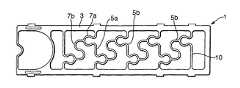
- FIG. 1is a schematic plan view of a first planar member in accordance with aspects of the present invention
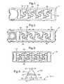
- FIG. 2is a schematic plan view of a second planar member in accordance with aspects of the present invention.
- FIG. 3is a schematic illustration of the planar members illustrated in FIGS. 1 and 2 overlaying each other;
- FIG. 4is a schematic illustration of utilisation of a support matrix arrangement in accordance with aspects of the present invention with regard to a gas shield about a weld site.
- a support matrix arrangement in accordance with aspects of the present inventionis designed to provide a substantially fixed spatial orientation, that is to say flat arrangement to support a material such as a flaccid porous material utilised to provide diffuse flow across the metering apparatus incorporating the matrix support arrangement.
- the term ‘flaccid’is intended to mean a material that is insufficiently rigid to support itself and therefore requires support, for example a woven cloth.
- the matrix support arrangement in accordance with aspects of the present inventionis utilised on both sides of a mesh or porous material in order to prevent it, that is to say the metering mesh, from buckling in either a convex, concave or indeterminate manner providing spurious gas flow results.
- FIGS. 1 to 3respectively illustrate a first planar member, a second planar member and an assembly of the planar members 1 , 2 as an overlay to allow a metering mesh to be located between them.
- each planar member 1 , 2comprises a frame 3 , 4 within which ribbon elements 5 , 6 extend across from one side to the other in order to support the mesh or porous material between the members 1 , 2 .
- the ribbon members 5 , 6are provided as lateral ribbon members 5 a , 6 a and intermediate ribbon members 5 b , 6 b .
- These respective ribbon members 5 , 6incorporate deflector portions 7 , 8 .
- the purpose of the ribbon members 5 , 6 and deflector portions 7 , 8is to ensure that an arrangement 9 formed by overlaying the members 1 , 2 accommodates bilateral thermal expansion or other distortion in the plane of the arrangement 9 , that is to say X and Y directions whilst remaining substantially distortion free in the plane Z perpendicular to this flat plane direction, that is to say perpendicular to the page upon which the Figs. are depicted. It will be appreciated by remaining substantially flat, that the effectiveness of the supported mesh material as a diffuser between the members 1 , 2 in the overlaid arrangement 9 is substantially stable in terms of gas control metering over a wide range of temperatures and so achieves consistency and repeatability of presentation of a gas shield and therefore process control.
- the respective ribbons 5 , 6 and deflector portions 7 , 8 in the respective planar members 1 , 2are mirror images of each other in order to appropriately support the intermediate mesh or porous material. This mirroring is about the major axis of the arrangement.
- the restrained mesh or mesh material as indicatedwill be potentially flaccid over the temperature ranges experienced and there will also be thermal expansion and contraction of the respective ribbon elements 5 , 6 .
- thermal expansion and contractioncan be accommodated by movement of these deflector portions 7 , 8 in the plane (X and Y) of the members 1 , 2 and therefore distortion outwardly prevented.
- Such distortion away from the plane of the arrangement 9 as indicatedwill create disparities and patch differentials in the matrix support which in turn will result in inconsistency in the gas flow metering effect across the arrangement 9 .
- the deflector portions 7 , 8 as illustrated in FIGS. 1 to 3will be loops with appropriate shaping, distribution and size to provide the desired deflection response, bilateral thermal expansion and retraction in the plane of the arrangement 9 , that is to say members 1 , 2 without deflection perpendicular to that plane.
- Lateral ribbon members 5 a , 6 bwill generally incorporate bulbous loops which have a neck portion consistent and similar to an Omega sign.
- the deflector portions 7 a , 7 bcan open and contract to accommodate expansion and contraction.
- Intermediate ribbon members 5 b , 6 bwill tend to incorporate U bend loops across bottom base portions, that is to say opposite to the neck part of the lateral deflector portions 7 a , 8 a in order to again allow expansion and contraction and anchor the other deflector portions to prevent outward buckling.
- the specific configuration of the ribbon members and deflector portionswill depend upon particular requirements.
- the members 1 , 2will be designed to suit the fit, form and function to achieve particular specification requirements in terms of supporting a mesh or metering control or otherwise for a diffuser in the arrangement 9 .
- spacing of the deflector portions, the relative size of deflector portions, the number of deflector portions and their general aspect ratiois not tied to a particular configuration but dependent upon requirements in terms of expected thermal expansion and contraction or other distortions which may be imposed upon the supported metering mesh or matrix.
- the ribbon membersextend substantially across the metering mesh or porous material and as such may constitute a gas flow blockage area across that mesh which may influence the characteristics of the metering mesh.
- these characteristicswill be substantially consistent for the reasons described above, that is to say the arrangement 9 will remain substantially flat and therefore there will be predictability and consistency with regard to the gas metering effect across the arrangement 9 .
- the ribbon width and number density of deflector portionswill be chosen not to have adverse effects upon the diffuser metering control process of the mesh supported by the arrangement 9 in accordance with aspects of the present invention.
- the ribbon memberswill have a width 10 which is equal to or less than the thickness of the members 1 , 2 . In such circumstances any blocking effects will generally be reduced as the metering mesh, whether it be woven or perforated or otherwise, becomes finer.
- an arrangement 9 in accordance with aspects of the present inventionwill comprise two members 1 , 2 overlaying each other and with mirror or symmetrical presentation of the deflector members.
- two members 1 , 2overlaying each other and with mirror or symmetrical presentation of the deflector members.
- three or more members with appropriate deflector membersmay be formed with respective mesh portions between them in order to ensure a flat configuration and therefore consistency with regard to metering effects.
- a matrix support arrangement in accordance with aspects of the present inventionwill be formed from any appropriate material to enable that mesh to be formed and provide reliable response over the temperature ranges and other conditions such as chemical environments.
- the members 1 , 2will be formed from a thin metal material appropriately cut or punched to achieve the desired ribbon members and deflector portions therein. However, in some circumstances plastics materials may be used.
- defector membersmay be shaped differently to the hooped configurations described above where necessary and appropriate in order to achieve bilateral deflection of the deflector portions preferentially to prevent outward buckling. It will also be understood where appropriate in view of the nature of size and other factors the deflector members may be differently shaped in different portions of the planar members to meet regional or zonal requirements within an arrangement in order to provide again an in plane bilateral deflection rather than outward buckling which would create inconsistencies in presentation and support of the metering mesh or porous material between the planar members.
- FIG. 4provides a schematic illustration of usage of a matrix support arrangement in accordance with aspects of the present invention with regard to presenting shielding for the welding process.
- a work piece 20is located upon an appropriate surface 21 such that the gas flow 22 provides local shielding about the work piece 20 .
- This gas flow 22is presented from a head 23 incorporating a metering mesh 24 between planar members 25 , 26 in accordance with aspects of the present invention.
- the mesh 24 as indicated previouslyis substantially flat and incorporates perforations or interstices which ensure that the gas flow 22 avoids as much as possible problems with respect to inconsistency of flow over different parts of the work piece 20 .
- a mesh support arrangementin accordance with aspects of the present invention, remains in a flat configuration there is consistency as indicated with the gas flow 22 cloud and therefore consistency in weld protection both pre-welding and post welding.
- a metering device in order to present a shieldwill provide consistency and so ideally causes a gentle stream free effusion of gas from its surface to give a homogenous vortex free cloud completely enveloping the work piece 20 during pre and post weld stages such that the weld formation or other process such as shape metal deposition (SMD) provides consistent results.
- the gas flowis presented through a conduit 27 and a metering mesh 24 causes diffusion to create this homogenous vortex free cloud about the work piece 20 .
Landscapes
- Engineering & Computer Science (AREA)
- Physics & Mathematics (AREA)
- Plasma & Fusion (AREA)
- Mechanical Engineering (AREA)
- Measuring Volume Flow (AREA)
Abstract
Description
Claims (13)
Applications Claiming Priority (3)
| Application Number | Priority Date | Filing Date | Title |
|---|---|---|---|
| GBGB0621388.8AGB0621388D0 (en) | 2006-10-27 | 2006-10-27 | A support matrix arrangement |
| GB0621388.8 | 2006-10-27 | ||
| PCT/GB2007/003705WO2008050080A1 (en) | 2006-10-27 | 2007-10-01 | A support matrix arrangement |
Publications (2)
| Publication Number | Publication Date |
|---|---|
| US20100001161A1 US20100001161A1 (en) | 2010-01-07 |
| US8487218B2true US8487218B2 (en) | 2013-07-16 |
Family
ID=37546077
Family Applications (1)
| Application Number | Title | Priority Date | Filing Date |
|---|---|---|---|
| US12/311,218Expired - Fee RelatedUS8487218B2 (en) | 2006-10-27 | 2007-10-01 | Support matrix arrangement |
Country Status (5)
| Country | Link |
|---|---|
| US (1) | US8487218B2 (en) |
| EP (1) | EP2078164B1 (en) |
| GB (1) | GB0621388D0 (en) |
| SG (1) | SG176424A1 (en) |
| WO (1) | WO2008050080A1 (en) |
Citations (17)
| Publication number | Priority date | Publication date | Assignee | Title |
|---|---|---|---|---|
| US1701805A (en)* | 1927-02-11 | 1929-02-12 | Irwin L Dunn | Explosion arrester |
| GB833837A (en) | 1958-02-24 | 1960-05-04 | Universal Oil Prod Co | Improvements in and relating to the concentrating of hydrogen |
| GB1021732A (en) | 1962-01-09 | 1966-03-09 | Union Carbide Corp | Improvements in or relating to electric arc working |
| US3576966A (en)* | 1967-03-27 | 1971-05-04 | Air Reduction | Arc-welding in narrow gap |
| US3895210A (en)* | 1973-06-11 | 1975-07-15 | Diamond Shamrock Corp | Apparatus for forming a dimensionally stable anode |
| US4007908A (en)* | 1975-05-09 | 1977-02-15 | Masoneilan International, Inc. | Process and device for attenuating noise caused by a valve during the expansion of a fluid |
| US4697345A (en)* | 1985-12-12 | 1987-10-06 | Cruce Evie C | Apparatus for segmenting edible peels of fruit and the like |
| US4902418A (en)* | 1985-11-22 | 1990-02-20 | Sulzer Brothers Limited | Element having a porous wall |
| US4919541A (en)* | 1986-04-07 | 1990-04-24 | Sulzer Brothers Limited | Gas-liquid mass transfer apparatus and method |
| US5486383A (en)* | 1994-08-08 | 1996-01-23 | Praxair Technology, Inc. | Laminar flow shielding of fluid jet |
| US5591241A (en)* | 1993-07-19 | 1997-01-07 | The Boc Group Plc | Liquid vapor contact apparatus |
| US5941281A (en)* | 1997-02-04 | 1999-08-24 | Fisher Controls International, Inc. | Fluid pressure reduction device |
| US5981897A (en)* | 1996-06-20 | 1999-11-09 | General Electric Company | Apparatus for distributing cover gas in reduced-width groove during welding |
| US6273938B1 (en)* | 1999-08-13 | 2001-08-14 | 3M Innovative Properties Company | Channel flow filter |
| EP1238594A2 (en) | 2001-03-05 | 2002-09-11 | Ivo Pera | Tobacco smoke filter and relative composition made of antioxidant and mineral substances |
| US6575617B2 (en)* | 2000-05-08 | 2003-06-10 | Sulzer Chemtech Ag | Static mixer with profiled layers |
| US20090045122A1 (en)* | 2007-08-17 | 2009-02-19 | Jun-Nan Lin | Fine bubble diffuser membrane for water and wastewater treatment |
- 2006
- 2006-10-27GBGBGB0621388.8Apatent/GB0621388D0/ennot_activeCeased
- 2007
- 2007-10-01WOPCT/GB2007/003705patent/WO2008050080A1/enactiveApplication Filing
- 2007-10-01USUS12/311,218patent/US8487218B2/ennot_activeExpired - Fee Related
- 2007-10-01EPEP07823964.7Apatent/EP2078164B1/ennot_activeNot-in-force
- 2007-10-01SGSG2011078565Apatent/SG176424A1/enunknown
Patent Citations (18)
| Publication number | Priority date | Publication date | Assignee | Title |
|---|---|---|---|---|
| US1701805A (en)* | 1927-02-11 | 1929-02-12 | Irwin L Dunn | Explosion arrester |
| GB833837A (en) | 1958-02-24 | 1960-05-04 | Universal Oil Prod Co | Improvements in and relating to the concentrating of hydrogen |
| GB1021732A (en) | 1962-01-09 | 1966-03-09 | Union Carbide Corp | Improvements in or relating to electric arc working |
| DE1515228B1 (en) | 1962-01-09 | 1971-06-16 | Union Carbide Corp | Method and device for processing workpieces by means of an arc under protective gas |
| US3576966A (en)* | 1967-03-27 | 1971-05-04 | Air Reduction | Arc-welding in narrow gap |
| US3895210A (en)* | 1973-06-11 | 1975-07-15 | Diamond Shamrock Corp | Apparatus for forming a dimensionally stable anode |
| US4007908A (en)* | 1975-05-09 | 1977-02-15 | Masoneilan International, Inc. | Process and device for attenuating noise caused by a valve during the expansion of a fluid |
| US4902418A (en)* | 1985-11-22 | 1990-02-20 | Sulzer Brothers Limited | Element having a porous wall |
| US4697345A (en)* | 1985-12-12 | 1987-10-06 | Cruce Evie C | Apparatus for segmenting edible peels of fruit and the like |
| US4919541A (en)* | 1986-04-07 | 1990-04-24 | Sulzer Brothers Limited | Gas-liquid mass transfer apparatus and method |
| US5591241A (en)* | 1993-07-19 | 1997-01-07 | The Boc Group Plc | Liquid vapor contact apparatus |
| US5486383A (en)* | 1994-08-08 | 1996-01-23 | Praxair Technology, Inc. | Laminar flow shielding of fluid jet |
| US5981897A (en)* | 1996-06-20 | 1999-11-09 | General Electric Company | Apparatus for distributing cover gas in reduced-width groove during welding |
| US5941281A (en)* | 1997-02-04 | 1999-08-24 | Fisher Controls International, Inc. | Fluid pressure reduction device |
| US6273938B1 (en)* | 1999-08-13 | 2001-08-14 | 3M Innovative Properties Company | Channel flow filter |
| US6575617B2 (en)* | 2000-05-08 | 2003-06-10 | Sulzer Chemtech Ag | Static mixer with profiled layers |
| EP1238594A2 (en) | 2001-03-05 | 2002-09-11 | Ivo Pera | Tobacco smoke filter and relative composition made of antioxidant and mineral substances |
| US20090045122A1 (en)* | 2007-08-17 | 2009-02-19 | Jun-Nan Lin | Fine bubble diffuser membrane for water and wastewater treatment |
Non-Patent Citations (1)
| Title |
|---|
| Anonymous, "Welding of Titanium Alloys," Welding Technology Institute of Australia, (online), http://www.wtia.com.au/pdf/TGN-MS-02%2, Apr. 21, 2006, pp. 1-6. |
Also Published As
| Publication number | Publication date |
|---|---|
| EP2078164B1 (en) | 2014-12-03 |
| US20100001161A1 (en) | 2010-01-07 |
| GB0621388D0 (en) | 2006-12-06 |
| EP2078164A1 (en) | 2009-07-15 |
| SG176424A1 (en) | 2011-12-29 |
| WO2008050080A1 (en) | 2008-05-02 |
Similar Documents
| Publication | Publication Date | Title |
|---|---|---|
| DE102006039238B4 (en) | flowmeter | |
| US5605399A (en) | Progressive motionless mixer | |
| US8487218B2 (en) | Support matrix arrangement | |
| CN111733380B (en) | Mask plate assembly, screen stretching method and evaporation device | |
| JPH0529879B2 (en) | ||
| JPWO2007129708A1 (en) | Wig clip | |
| JPH0229919B2 (en) | ||
| JPH10135132A (en) | Gas circulation system, gas circulation method and lithographic apparatus | |
| JP2959644B2 (en) | Large screen projection display | |
| CN110629156A (en) | Mask plate and preparation method thereof | |
| EP0971363B1 (en) | Support grid for a nuclear reactor fuel assembly | |
| KR20200040474A (en) | Mask integrated frame and producing method of mask integrated frame | |
| US11932003B2 (en) | Precision cut printing screen | |
| TW492034B (en) | Masking device for a flat-screen colour-display cathode-ray tube with a tensioned shadow mask made of Fe-Ni alloys | |
| US6415011B1 (en) | Spacer and a fuel assembly for a nuclear boiling water reactor | |
| US6420823B1 (en) | Shadow mask structure and color CRT | |
| US6650038B1 (en) | CRT having a tension mask with reinforcing support means | |
| JP5032475B2 (en) | Fuel assemblies for pressurized water reactors | |
| RU2827693C1 (en) | Device for arrangement of catalytic system in contact apparatus of ammonia oxidation, contact apparatus for oxidation of ammonia and method of device installation in apparatus | |
| JP7601253B2 (en) | Heat Diffusion Device | |
| JP2004346645A (en) | Partition sheet, partition wall, and method of installing partition wall | |
| JP4401046B2 (en) | Mask for screen printing | |
| JP2021517865A (en) | Cooling device and method for operating the cooling device | |
| CN209146426U (en) | A kind of inverted arch slit type bursting disc of failure by shear | |
| JP7746617B1 (en) | Water intake panel and method for manufacturing water intake panel |
Legal Events
| Date | Code | Title | Description |
|---|---|---|---|
| AS | Assignment | Owner name:ROLLS-ROYCE PLC, GREAT BRITAIN Free format text:ASSIGNMENT OF ASSIGNORS INTEREST;ASSIGNOR:BISHOP, JEFFREY CHARLES;REEL/FRAME:022475/0500 Effective date:20090225 | |
| FEPP | Fee payment procedure | Free format text:PAYOR NUMBER ASSIGNED (ORIGINAL EVENT CODE: ASPN); ENTITY STATUS OF PATENT OWNER: LARGE ENTITY | |
| STCF | Information on status: patent grant | Free format text:PATENTED CASE | |
| FPAY | Fee payment | Year of fee payment:4 | |
| MAFP | Maintenance fee payment | Free format text:PAYMENT OF MAINTENANCE FEE, 8TH YEAR, LARGE ENTITY (ORIGINAL EVENT CODE: M1552); ENTITY STATUS OF PATENT OWNER: LARGE ENTITY Year of fee payment:8 | |
| FEPP | Fee payment procedure | Free format text:MAINTENANCE FEE REMINDER MAILED (ORIGINAL EVENT CODE: REM.); ENTITY STATUS OF PATENT OWNER: LARGE ENTITY | |
| LAPS | Lapse for failure to pay maintenance fees | Free format text:PATENT EXPIRED FOR FAILURE TO PAY MAINTENANCE FEES (ORIGINAL EVENT CODE: EXP.); ENTITY STATUS OF PATENT OWNER: LARGE ENTITY | |
| STCH | Information on status: patent discontinuation | Free format text:PATENT EXPIRED DUE TO NONPAYMENT OF MAINTENANCE FEES UNDER 37 CFR 1.362 | |
| FP | Lapsed due to failure to pay maintenance fee | Effective date:20250716 |