US8486575B2 - Passive hydrogen vent for a fuel cell - Google Patents
Passive hydrogen vent for a fuel cellDownload PDFInfo
- Publication number
- US8486575B2 US8486575B2US10/772,699US77269904AUS8486575B2US 8486575 B2US8486575 B2US 8486575B2US 77269904 AUS77269904 AUS 77269904AUS 8486575 B2US8486575 B2US 8486575B2
- Authority
- US
- United States
- Prior art keywords
- hydrogen
- fuel cell
- enclosure
- vent
- coolant
- Prior art date
- Legal status (The legal status is an assumption and is not a legal conclusion. Google has not performed a legal analysis and makes no representation as to the accuracy of the status listed.)
- Expired - Fee Related, expires
Links
Images


Classifications
- H—ELECTRICITY
- H01—ELECTRIC ELEMENTS
- H01M—PROCESSES OR MEANS, e.g. BATTERIES, FOR THE DIRECT CONVERSION OF CHEMICAL ENERGY INTO ELECTRICAL ENERGY
- H01M8/00—Fuel cells; Manufacture thereof
- H01M8/24—Grouping of fuel cells, e.g. stacking of fuel cells
- H01M8/2465—Details of groupings of fuel cells
- H01M8/247—Arrangements for tightening a stack, for accommodation of a stack in a tank or for assembling different tanks
- H01M8/2475—Enclosures, casings or containers of fuel cell stacks
- H—ELECTRICITY
- H01—ELECTRIC ELEMENTS
- H01M—PROCESSES OR MEANS, e.g. BATTERIES, FOR THE DIRECT CONVERSION OF CHEMICAL ENERGY INTO ELECTRICAL ENERGY
- H01M8/00—Fuel cells; Manufacture thereof
- H01M8/04—Auxiliary arrangements, e.g. for control of pressure or for circulation of fluids
- H01M8/04007—Auxiliary arrangements, e.g. for control of pressure or for circulation of fluids related to heat exchange
- H—ELECTRICITY
- H01—ELECTRIC ELEMENTS
- H01M—PROCESSES OR MEANS, e.g. BATTERIES, FOR THE DIRECT CONVERSION OF CHEMICAL ENERGY INTO ELECTRICAL ENERGY
- H01M8/00—Fuel cells; Manufacture thereof
- H01M8/04—Auxiliary arrangements, e.g. for control of pressure or for circulation of fluids
- H01M8/04082—Arrangements for control of reactant parameters, e.g. pressure or concentration
- H01M8/04089—Arrangements for control of reactant parameters, e.g. pressure or concentration of gaseous reactants
- H—ELECTRICITY
- H01—ELECTRIC ELEMENTS
- H01M—PROCESSES OR MEANS, e.g. BATTERIES, FOR THE DIRECT CONVERSION OF CHEMICAL ENERGY INTO ELECTRICAL ENERGY
- H01M8/00—Fuel cells; Manufacture thereof
- H01M8/04—Auxiliary arrangements, e.g. for control of pressure or for circulation of fluids
- H01M8/04007—Auxiliary arrangements, e.g. for control of pressure or for circulation of fluids related to heat exchange
- H01M8/04029—Heat exchange using liquids
- Y—GENERAL TAGGING OF NEW TECHNOLOGICAL DEVELOPMENTS; GENERAL TAGGING OF CROSS-SECTIONAL TECHNOLOGIES SPANNING OVER SEVERAL SECTIONS OF THE IPC; TECHNICAL SUBJECTS COVERED BY FORMER USPC CROSS-REFERENCE ART COLLECTIONS [XRACs] AND DIGESTS
- Y02—TECHNOLOGIES OR APPLICATIONS FOR MITIGATION OR ADAPTATION AGAINST CLIMATE CHANGE
- Y02E—REDUCTION OF GREENHOUSE GAS [GHG] EMISSIONS, RELATED TO ENERGY GENERATION, TRANSMISSION OR DISTRIBUTION
- Y02E60/00—Enabling technologies; Technologies with a potential or indirect contribution to GHG emissions mitigation
- Y02E60/30—Hydrogen technology
- Y02E60/50—Fuel cells
- Y—GENERAL TAGGING OF NEW TECHNOLOGICAL DEVELOPMENTS; GENERAL TAGGING OF CROSS-SECTIONAL TECHNOLOGIES SPANNING OVER SEVERAL SECTIONS OF THE IPC; TECHNICAL SUBJECTS COVERED BY FORMER USPC CROSS-REFERENCE ART COLLECTIONS [XRACs] AND DIGESTS
- Y02—TECHNOLOGIES OR APPLICATIONS FOR MITIGATION OR ADAPTATION AGAINST CLIMATE CHANGE
- Y02P—CLIMATE CHANGE MITIGATION TECHNOLOGIES IN THE PRODUCTION OR PROCESSING OF GOODS
- Y02P70/00—Climate change mitigation technologies in the production process for final industrial or consumer products
- Y02P70/50—Manufacturing or production processes characterised by the final manufactured product
Definitions
- the present inventionrelates to fuel cells; and more particularly, to various enclosures in a fuel cell system.
- Fuel cellshave been used as a power source in many applications. For example, fuel cells have been proposed for use in electrical vehicular power plants to replace internal combustion engines.
- PEMproton exchange membrane
- hydrogenis supplied to the anode of the fuel cell and oxygen is supplied as the oxidant to the cathode.
- the oxygencan be either a pure form (O 2 ) or air (a mixture of O 2 and N2).
- PEM fuel cellsinclude a membrane electrode assembly (MEA) comprising a thin, proton transmissive, non-electrically conductive, gas impermeable, solid polymer electrolyte membrane having the anode catalyst on one face and the cathode catalyst on the opposite face.
- MEAmembrane electrode assembly
- the MEAis sandwiched between a pair of non-porous, electrically conductive elements or plates which (1) serve as current collectors for the anode and cathode, and (2) contain appropriate channels and/or openings formed therein for distributing the fuel cell's gaseous reactants over the surfaces of the respective anode and cathode catalysts.
- fuel cellis typically used to refer to either a single cell or a plurality of cells (stack) depending on the context.
- a plurality of individual cellsare typically bundled together to form a fuel cell stack and are commonly arranged in electrical series.
- Each cell within the stackincludes the membrane electrode assembly (MEA) described earlier, and each such MEA provides its increment of voltage.
- MEAmembrane electrode assembly
- the electrically conductive plates sandwiching the MEAsmay contain an array of grooves in the faces thereof that define a reactant flow field for distributing the fuel cell's gaseous reactants (i.e., hydrogen and oxygen in the form of air) over the surfaces of the respective cathode and anode.
- These reactant flow fieldsgenerally include a plurality of lands that define a plurality of flow channels therebetween through which the gaseous reactants flow from a supply header at one end of the flow channels to an exhaust header at the opposite end of the flow channels.
- a plurality of cellsare stacked together in electrical series while being separated by a gas impermeable, electrically conductive bipolar plate.
- the bipolar plateis an assembly formed by securing a pair of thin metal sheets having reactant flow fields formed on their external face surfaces.
- an internal coolant flow fieldis provided between the metal plates of the bipolar plate assembly.
- Hydrogenhas been known to accumulate in the coolant system of the fuel cell. For example, hydrogen has been found to migrate into the coolant flow field and accumulate in the cooling system. Hydrogen may also disassociate from the coolant itself. Previous approaches to venting accumulated hydrogen from a fuel cell have included use of a hydrogen detector and/or fan to actively ventilate the reservoir. These electrical devices consume electricity, reducing the efficiency of the fuel cell. In addition, they can result in ventilating coolant vapor, thereby evaporating the coolant.
- the present inventionis capable of eliminating one or more of the disadvantages discussed above.
- hydrogenmay also accumulate in a fuel cell housing enclosure and/or in fuel cell system enclosures other than the coolant flow path.
- hydrogenmay leak from various pipes and fittings of the hydrogen flow path, including the hydrogen supply.
- Certain aspects of the present inventioncan also enable the venting of accumulated hydrogen from these other enclosures of a fuel cell.
- a fuel cellin accordance with one aspect of the present invention a fuel cell is provided.
- the fuel cellhas a hydrogen flow path adapted to pass hydrogen into communication with an anode catalyst of an MEA.
- a coolant flow pathis adapted to pass coolant through the fuel cell to cool the fuel cell.
- An enclosureencompasses at least a portion of the hydrogen flow path, the coolant flow path, or both.
- a hydrogen ventis adapted to vent hydrogen from the enclosure without reliance upon any electrical device.
- a method of manufacturing a fuel cellincludes creating a hydrogen fuel flow path to conduct hydrogen through the fuel cell.
- An enclosureis created which captures hydrogen that leaks, directly or indirectly, from the hydrogen flow path.
- the concentration of hydrogen which leaks into the enclosureis passively maintained below a level of about 4 percent.
- FIG. 1is an exploded isometric view of a PEM fuel stack
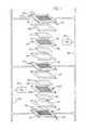
- FIG. 2is a schematic view of a fuel cell including various enclosures, each having a hydrogen vent according to the present invention.
- FIG. 1schematically depicts a partial PEM fuel cell stack having a pair of membrane-electrode-assemblies (MEAs) 8 and 10 separated from each other by a non-porous, electrically-conductive bipolar plate 12 .
- MEAsmembrane-electrode-assemblies
- Each of the MEAs 8 , 10have a cathode face 8 c , 10 c and an anode face 8 a , 10 a .
- the MEAs 8 and 10 , and bipolar plate 12are stacked together between non-porous, electrically-conductive, liquid-cooled bipolar plates 14 and 16 .
- the bipolar plates 12 , 14 and 16each include flow fields 18 , 20 and 22 having a plurality of flow channels formed in the faces of the plates for distributing fuel and oxidant gases (i.e., H 2 & O 2 ) to the reactive faces of the MEAs 8 and 10 .
- Nonconductive gaskets or seals 26 , 28 , 30 , and 32provide a seal and electrical insulation between the several plates of the fuel cell stack.
- Porous, gas permeable, electrically conductive sheets 34 , 36 , 38 and 40press up against the electrode faces of the MEAs 8 and 10 and serve as primary current collectors for the electrodes.
- Primary current collectors 34 , 36 , 38 and 40also provide mechanical supports for the MEAs 8 and 10 , especially at locations where the MEAs are otherwise unsupported in the flow field.
- Suitable primary current collectorsinclude carbon/graphite paper/cloth, fine mesh noble metal screens, open cell noble metal foams, and the like which conduct current from the electrodes while allowing gas to pass therethrough.
- Bipolar plates 14 and 16press up against the primary current collector 34 on the cathode face 8 c of MEA 8 and primary current collector 40 on the anode face 10 a of MEA 10 , while the bipolar plate 12 presses up against the primary current collector 36 on the anode face 8 a of MEA 8 and against the primary current collector 38 on the cathode face 10 c of MEA 10 .
- An oxidant gassuch as oxygen or air is supplied to the cathode side of the fuel cell stack from a storage tank 46 via appropriate supply plumbing 42 .
- a fuelsuch as hydrogen is supplied to the anode side of the fuel cell from a storage tank 48 via appropriate supply plumbing 44 .
- the oxygen tank 46may be eliminated, and air supplied to the cathode side from the ambient.
- the hydrogen tank 48may be eliminated and hydrogen supplied to the anode side from a reformer which catalytically generates hydrogen from methanol or a liquid hydrocarbon (e.g., gasoline).
- Exhaust plumbing(not shown) for both the H 2 and O 2 /air sides of the MEAs is also provided for removing H 2 -depleted anode gas from the anode flow field and O 2 -depleted cathode gas from the cathode flow field.
- Coolant plumbing 50 and 52is provided for supplying and exhausting liquid coolant to the bipolar plates 14 and 16 , as needed.
- Each of the bipolar plates 14 and 16include a plurality of flow channels forming a coolant flow field.
- the cooling systemincludes inlet line or pipe 50 in fluid communication, via an appropriate manifold to the coolant flow fields of bipolar plates 14 and 16 . After traveling through the coolant flow fields, the coolant passes out of the fuel cell stack 60 via an appropriate header to coolant outlet line 52 .
- An electronic control valve 62controls passage of the coolant through bypass line 68 and/or through line 64 to a radiator and/or fan 66 .
- bypass line 68 and/or through line 64to a radiator and/or fan 66 .
- the coolant from the fuel cell stack 60mixes with coolant flowing from the coolant reservoir 72 through line 70 , as necessary.
- a pump 74pumps the coolant back into the fuel cell stack 60 via line or pipe 76 .
- a drain line 84is also provided to permit coolant to be drained from the fuel cell stack 60 into the coolant reservoir 72 by manipulation of a drain valve 86 .
- the coolanttravels through the fuel cell stack 60 it comes into close proximity to hydrogen also traveling through the fuel cell stack 60 .
- the hydrogen and the coolantmay be traveling in adjacent channels of their respective flow fields separated only by a sealant. Hydrogen has the potential to migrate into the coolant flow channels or the enclosure that defines the coolant flow path.
- any hydrogen that might have migrated into the coolant enclosuretends to accumulate in the highest point within the coolant system. Typically, this highest point is in the coolant reservoir 72 . Consequently, it is desirable to locate a hydrogen vent 88 in a wall of the coolant enclosure defining the flow path; preferably in a wall 90 of the coolant reservoir 72 .
- the coolant flow pathis defined by the enclosure created by, e.g., the flow channels in the fuel cell stack 60 , the coolant reservoir 72 and the lines 50 , 52 , 64 , 68 , 70 and 76 .
- the hydrogen vent 88may be placed within a wall of any of these enclosure components of the coolant flow path.
- the hydrogen vent 88 of this embodimentis adapted to allow hydrogen to pass therethrough while simultaneously preventing any coolant (including evaporating coolant vapor) from passing therethrough.
- the hydrogen vent 88is preferably adapted to prevent a frame front from passing into the enclosure through the hydrogen vent 88 .
- the hydrogen vent 88provides pores (represented by the cross-hatching) which are sufficiently large to allow hydrogen molecules to pass therethrough. The pores are also preferably sufficiently small that coolant, including coolant vapors, cannot pass therethrough.
- the hydrogen vent 88is passive.
- “passive”means that the hydrogen vent does not require any electrical or other active components to function.
- the hydrogen vent 88requires no electrical components such as a sensor, controller, or fan are required.
- the hydrogen vent 88is preferably adapted to passively vent hydrogen such that the hydrogen remains below about 4 percent within the enclosure 72 ; and more preferably, below about 1 percent.
- the hydrogen vent 88is preferably made of a porous material selected from the group consisting of cellulose, plastic (for example, a foamed plastic) or metal (for example, a sintered metal).
- the fuel cell systemhas various enclosures, including a fuel cell stack enclosure 92 .
- This fuel cell stack enclosure 92encompasses an area surrounding a part of the coolant flow path. For example, it includes inlet coolant 51 , the coolant flow fields, and coolant outlet 53 .
- the fuel cell enclosure 92includes an area surrounding a part of the hydrogen flow path and the oxygen flow path.
- the fuel cell enclosuresurrounds the inlet 94 , hydrogen flow field, and the outlet 96 .
- the fittings and headers which connect the various components of the hydrogen flow path within the fuel cell enclosure 92are potential sources for hydrogen leaks.
- hydrogen which may have migrated into the cooling systemmay potentially leak from corresponding fittings and manifolds from the coolant flow path within the fuel cell enclosure 92 .
- a hydrogen vent 98is located within a wall 100 of the fuel cell enclosure 92 . This hydrogen vent 98 has the same properties discussed above with respect to the hydrogen vent 88 of the coolant flow reservoir 72 .
- the fuel cell system enclosure defining the coolant flow path, including lines 50 , 52 , 64 , 68 , 76 and reservoir 72 , the hydrogen supply tank 48 and the fuel cell enclosure 92are all located within an overall fuel cell system enclosure 110 .
- This system enclosure 110encompasses an area surrounding the coolant reservoir 72 and the fuel cell stack enclosure 92 .
- hydrogen vented through the hydrogen vent 88 of the coolant reservoir 72 or through the hydrogen vent 98 of the fuel cell enclosure 92is still contained within the system enclosure 110 .
- the hydrogen supply tank 48is located within the system enclosure 110 .
- the hydrogen tank 48may be replaced with a reformer.
- the entire hydrogen flow pathis enclosed within the system enclosure 110 , although H 2 -depleted gas leaving the fuel cell stack 60 via outlet 96 exits the system enclosure 110 .
- this system enclosure 110includes various potential hydrogen sources.
- hydrogenmay be vented into the system enclosure 110 by the coolant reservoir 72 hydrogen vent 88 or by the fuel cell enclosure 92 hydrogen vent 98 .
- hydrogenmay potentially leak from the hydrogen supply tank 48 or reformer and associated hydrogen flow lines 111 and fittings.
- a hydrogen vent 108is located within a wall 112 of the system enclosure 110 to vent hydrogen to the atmosphere. This hydrogen vent 108 has the same properties discussed above with respect to the previously identified hydrogen vents 88 , 98 .
- the hydrogen supply tankmay be located outside of the system enclosure, but have its own hydrogen supply enclosure encompassing the area around the hydrogen supply tank.
- an oxygen supply tankmay additionally be located within the system enclosure of FIG. 2 .
Landscapes
- Life Sciences & Earth Sciences (AREA)
- Engineering & Computer Science (AREA)
- Manufacturing & Machinery (AREA)
- Sustainable Development (AREA)
- Sustainable Energy (AREA)
- Chemical & Material Sciences (AREA)
- Chemical Kinetics & Catalysis (AREA)
- Electrochemistry (AREA)
- General Chemical & Material Sciences (AREA)
- Fuel Cell (AREA)
Abstract
Description
Claims (15)
Priority Applications (1)
| Application Number | Priority Date | Filing Date | Title |
|---|---|---|---|
| US10/772,699US8486575B2 (en) | 2004-02-05 | 2004-02-05 | Passive hydrogen vent for a fuel cell |
Applications Claiming Priority (1)
| Application Number | Priority Date | Filing Date | Title |
|---|---|---|---|
| US10/772,699US8486575B2 (en) | 2004-02-05 | 2004-02-05 | Passive hydrogen vent for a fuel cell |
Publications (2)
| Publication Number | Publication Date |
|---|---|
| US20050175873A1 US20050175873A1 (en) | 2005-08-11 |
| US8486575B2true US8486575B2 (en) | 2013-07-16 |
Family
ID=34826639
Family Applications (1)
| Application Number | Title | Priority Date | Filing Date |
|---|---|---|---|
| US10/772,699Expired - Fee RelatedUS8486575B2 (en) | 2004-02-05 | 2004-02-05 | Passive hydrogen vent for a fuel cell |
Country Status (1)
| Country | Link |
|---|---|
| US (1) | US8486575B2 (en) |
Cited By (1)
| Publication number | Priority date | Publication date | Assignee | Title |
|---|---|---|---|---|
| US12438165B2 (en) | 2021-08-24 | 2025-10-07 | Hydrogenics Corporation | Systems and methods for ventilating a fuel cell enclosure |
Families Citing this family (3)
| Publication number | Priority date | Publication date | Assignee | Title |
|---|---|---|---|---|
| US7807309B2 (en)* | 2004-09-03 | 2010-10-05 | Gm Global Technology Operations, Inc. | Integrated coolant header venting for a fuel cell stack |
| US7576660B2 (en)* | 2007-05-30 | 2009-08-18 | Ford Global Technologies, Llc | Fuel retention monitoring system for a pressurized hydrogen storage tank on a vehicle and method of use |
| JP2012521070A (en)* | 2009-03-18 | 2012-09-10 | ユーティーシー パワー コーポレイション | Fuel cell with purge manifold |
Citations (58)
| Publication number | Priority date | Publication date | Assignee | Title |
|---|---|---|---|---|
| US4168349A (en)* | 1978-04-27 | 1979-09-18 | Westinghouse Electric Corp. | Iron/air battery system having circulating electrolyte and a horizontal cell configuration |
| US4344832A (en) | 1979-07-03 | 1982-08-17 | Licentia Patent-Verwaltungs-G.M.B.H. | Electrode system for a fuel or electrolysis cell arrangement |
| US4769297A (en) | 1987-11-16 | 1988-09-06 | International Fuel Cells Corporation | Solid polymer electrolyte fuel cell stack water management system |
| US5108849A (en) | 1989-08-30 | 1992-04-28 | Her Majesty The Queen In Right Of Canada, As Represented By The Minister Of National Defence In Her Britannic Majesty's Government Of The United Kingdom Of Great Britain And Northern Ireland | Fuel cell fluid flow field plate |
| US5230966A (en) | 1991-09-26 | 1993-07-27 | Ballard Power Systems Inc. | Coolant flow field plate for electrochemical fuel cells |
| US5252410A (en) | 1991-09-13 | 1993-10-12 | Ballard Power Systems Inc. | Lightweight fuel cell membrane electrode assembly with integral reactant flow passages |
| US5264299A (en) | 1991-12-26 | 1993-11-23 | International Fuel Cells Corporation | Proton exchange membrane fuel cell support plate and an assembly including the same |
| US5300370A (en) | 1992-11-13 | 1994-04-05 | Ballard Power Systems Inc. | Laminated fluid flow field assembly for electrochemical fuel cells |
| US5482680A (en) | 1992-10-09 | 1996-01-09 | Ballard Power Systems, Inc. | Electrochemical fuel cell assembly with integral selective oxidizer |
| US5514487A (en) | 1994-12-27 | 1996-05-07 | Ballard Power Systems Inc. | Edge manifold assembly for an electrochemical fuel cell stack |
| US5521018A (en) | 1993-12-10 | 1996-05-28 | Ballard Power Systems Inc. | Embossed fluid flow field plate for electrochemical fuel cells |
| US5547776A (en) | 1991-01-15 | 1996-08-20 | Ballard Power Systems Inc. | Electrochemical fuel cell stack with concurrently flowing coolant and oxidant streams |
| US5623390A (en)* | 1993-12-15 | 1997-04-22 | Alps Electric Co., Ltd. | Computer having nickel-hydrogen battery and vent holes sealed with porous film |
| US5624769A (en) | 1995-12-22 | 1997-04-29 | General Motors Corporation | Corrosion resistant PEM fuel cell |
| US5641586A (en) | 1995-12-06 | 1997-06-24 | The Regents Of The University Of California Office Of Technology Transfer | Fuel cell with interdigitated porous flow-field |
| US5663113A (en) | 1994-04-25 | 1997-09-02 | Asahi Kasei Kogyo Kabushiki Kaisha | Ammoxidation catalyst composition |
| US5686199A (en) | 1996-05-07 | 1997-11-11 | Alliedsignal Inc. | Flow field plate for use in a proton exchange membrane fuel cell |
| US5707755A (en) | 1996-12-09 | 1998-01-13 | General Motors Corporation | PEM/SPE fuel cell |
| US5769909A (en) | 1996-05-31 | 1998-06-23 | International Fuel Cells Corp. | Method and apparatus for desulfurizing fuel gas |
| US5773160A (en) | 1994-06-24 | 1998-06-30 | Ballard Power Systems Inc. | Electrochemical fuel cell stack with concurrent flow of coolant and oxidant streams and countercurrent flow of fuel and oxidant streams |
| US5776624A (en) | 1996-12-23 | 1998-07-07 | General Motors Corporation | Brazed bipolar plates for PEM fuel cells |
| US5804326A (en) | 1996-12-20 | 1998-09-08 | Ballard Power Systems Inc. | Integrated reactant and coolant fluid flow field layer for an electrochemical fuel cell |
| US5846668A (en) | 1996-03-07 | 1998-12-08 | Tanaka Kikinzoku Kogyo K. K. | Fuel cell, electrolytic cell and process of cooling and/or dehumidifying same |
| US5874182A (en) | 1995-12-18 | 1999-02-23 | Ballard Power Systems Inc. | Method and apparatus for reducing reactant crossover in a liquid feed electrochemical fuel cell |
| US5928807A (en) | 1995-11-15 | 1999-07-27 | Ballard Power Systems Inc. | Integrated seal for a PEM fuel cell |
| US5945232A (en) | 1998-04-03 | 1999-08-31 | Plug Power, L.L.C. | PEM-type fuel cell assembly having multiple parallel fuel cell sub-stacks employing shared fluid plate assemblies and shared membrane electrode assemblies |
| US5981098A (en) | 1997-08-28 | 1999-11-09 | Plug Power, L.L.C. | Fluid flow plate for decreased density of fuel cell assembly |
| US6013385A (en)* | 1997-07-25 | 2000-01-11 | Emprise Corporation | Fuel cell gas management system |
| WO2000017952A1 (en) | 1998-09-18 | 2000-03-30 | Energy Partners, L.C. | Self-humidifying fuel cell |
| US6054228A (en) | 1996-06-06 | 2000-04-25 | Lynntech, Inc. | Fuel cell system for low pressure operation |
| US6099984A (en) | 1997-12-15 | 2000-08-08 | General Motors Corporation | Mirrored serpentine flow channels for fuel cell |
| US6146779A (en) | 1999-04-01 | 2000-11-14 | Plug Power Inc. | Fluid flow plate, fuel cell assembly system, and method employing same for controlling heat in fuel cells |
| US6159626A (en) | 1999-07-06 | 2000-12-12 | General Motors Corporation | Fuel cell system logic for differentiating between rapid and normal shutdown commands |
| US6159629A (en) | 1998-12-17 | 2000-12-12 | Ballard Power Systems Inc. | Volume effecient layered manifold assembly for electrochemical fuel cell stacks |
| US6174616B1 (en) | 1998-10-07 | 2001-01-16 | Plug Power Inc. | Fuel cell assembly unit for promoting fluid service and design flexibility |
| US6186254B1 (en) | 1996-05-29 | 2001-02-13 | Xcelliss Fuel Cell Engines Inc. | Temperature regulating system for a fuel cell powered vehicle |
| US6261710B1 (en) | 1998-11-25 | 2001-07-17 | Institute Of Gas Technology | Sheet metal bipolar plate design for polymer electrolyte membrane fuel cells |
| US6277509B1 (en)* | 1999-04-12 | 2001-08-21 | International Fuel Cells Llc | Hydride bed water recovery system for a fuel cell power plant |
| US6306354B1 (en) | 1996-05-17 | 2001-10-23 | International Fuel Cells, Llc | Shift converter |
| US6309773B1 (en) | 1999-12-13 | 2001-10-30 | General Motors Corporation | Serially-linked serpentine flow channels for PEM fuel cell |
| US6322919B1 (en) | 1999-08-16 | 2001-11-27 | Alliedsignal Inc. | Fuel cell and bipolar plate for use with same |
| FR2810795A1 (en) | 2000-06-27 | 2001-12-28 | Technicatome | Bipolar plate for a fuel cell comprises two metallic plates separated by segments and having recesses for the production of a composite conducting body in a single molding operation |
| US6358642B1 (en) | 1999-12-02 | 2002-03-19 | General Motors Corporation | Flow channels for fuel cell |
| US6360835B1 (en) | 2000-02-16 | 2002-03-26 | General Motors Corporation | Thermal management of fuel-cell-powered vehicles |
| US6372376B1 (en) | 1999-12-07 | 2002-04-16 | General Motors Corporation | Corrosion resistant PEM fuel cell |
| US6376112B1 (en) | 2000-02-11 | 2002-04-23 | General Motors Corporation | Controlled shutdown of a fuel cell |
| US20020114984A1 (en)* | 2001-02-21 | 2002-08-22 | Edlund David J. | Fuel cell system with stored hydrogen |
| US20020160245A1 (en)* | 2001-04-27 | 2002-10-31 | Suat Genc | Release valve and method for venting a system |
| US6503653B2 (en) | 2001-02-23 | 2003-01-07 | General Motors Corporation | Stamped bipolar plate for PEM fuel cell stack |
| US20030064266A1 (en)* | 2000-03-31 | 2003-04-03 | Kabushiki Kaisha Toshiba | Polymer electrolyte fuel cell stack and method for operating the same and gas vent valve |
| US20030118881A1 (en)* | 2001-07-31 | 2003-06-26 | Plug Power Inc. | Method and apparatus for collecting condensate in an integrated fuel cell system |
| US20030232228A1 (en)* | 2002-06-17 | 2003-12-18 | Grasso Albert P. | Coolant mixture separator assembly for use in a polymer electrolyte membrane (PEM) fuel cell power plant |
| US20040001982A1 (en)* | 2002-07-01 | 2004-01-01 | Reiser Carl A. | Initiating operation of an electric vehicle or other load powered by a fuel cell at sub-freezing temperature |
| US20040062964A1 (en)* | 2002-09-30 | 2004-04-01 | Kabushiki Kaisha Toshiba | Direct methanol fuel cell system |
| US20040151962A1 (en)* | 2003-01-31 | 2004-08-05 | Paul Adams | Fuel cartridge for fuel cells |
| US20040175608A1 (en)* | 2003-03-07 | 2004-09-09 | Lisi Daniel J. | Polymeric separator plates |
| US20050058861A1 (en)* | 2003-09-17 | 2005-03-17 | Pettit William H. | Method and apparatus for hydrogen detection and dilution |
| US20050106438A1 (en)* | 2003-11-19 | 2005-05-19 | Ralph Hobmeyr | Vehicle plumbing to release hydrogen from fluid |
- 2004
- 2004-02-05USUS10/772,699patent/US8486575B2/ennot_activeExpired - Fee Related
Patent Citations (60)
| Publication number | Priority date | Publication date | Assignee | Title |
|---|---|---|---|---|
| US4168349A (en)* | 1978-04-27 | 1979-09-18 | Westinghouse Electric Corp. | Iron/air battery system having circulating electrolyte and a horizontal cell configuration |
| US4344832A (en) | 1979-07-03 | 1982-08-17 | Licentia Patent-Verwaltungs-G.M.B.H. | Electrode system for a fuel or electrolysis cell arrangement |
| US4769297A (en) | 1987-11-16 | 1988-09-06 | International Fuel Cells Corporation | Solid polymer electrolyte fuel cell stack water management system |
| US5108849A (en) | 1989-08-30 | 1992-04-28 | Her Majesty The Queen In Right Of Canada, As Represented By The Minister Of National Defence In Her Britannic Majesty's Government Of The United Kingdom Of Great Britain And Northern Ireland | Fuel cell fluid flow field plate |
| US5547776A (en) | 1991-01-15 | 1996-08-20 | Ballard Power Systems Inc. | Electrochemical fuel cell stack with concurrently flowing coolant and oxidant streams |
| WO1994009519A1 (en) | 1991-09-13 | 1994-04-28 | Ballard Power Systems | Lightweight fuel cell membrane electrode assembly with integral reactant flow passages |
| US5252410A (en) | 1991-09-13 | 1993-10-12 | Ballard Power Systems Inc. | Lightweight fuel cell membrane electrode assembly with integral reactant flow passages |
| US5230966A (en) | 1991-09-26 | 1993-07-27 | Ballard Power Systems Inc. | Coolant flow field plate for electrochemical fuel cells |
| US5264299A (en) | 1991-12-26 | 1993-11-23 | International Fuel Cells Corporation | Proton exchange membrane fuel cell support plate and an assembly including the same |
| US5482680A (en) | 1992-10-09 | 1996-01-09 | Ballard Power Systems, Inc. | Electrochemical fuel cell assembly with integral selective oxidizer |
| US5300370A (en) | 1992-11-13 | 1994-04-05 | Ballard Power Systems Inc. | Laminated fluid flow field assembly for electrochemical fuel cells |
| US5521018A (en) | 1993-12-10 | 1996-05-28 | Ballard Power Systems Inc. | Embossed fluid flow field plate for electrochemical fuel cells |
| US5623390A (en)* | 1993-12-15 | 1997-04-22 | Alps Electric Co., Ltd. | Computer having nickel-hydrogen battery and vent holes sealed with porous film |
| US5663113A (en) | 1994-04-25 | 1997-09-02 | Asahi Kasei Kogyo Kabushiki Kaisha | Ammoxidation catalyst composition |
| US5773160A (en) | 1994-06-24 | 1998-06-30 | Ballard Power Systems Inc. | Electrochemical fuel cell stack with concurrent flow of coolant and oxidant streams and countercurrent flow of fuel and oxidant streams |
| US5514487A (en) | 1994-12-27 | 1996-05-07 | Ballard Power Systems Inc. | Edge manifold assembly for an electrochemical fuel cell stack |
| US5928807A (en) | 1995-11-15 | 1999-07-27 | Ballard Power Systems Inc. | Integrated seal for a PEM fuel cell |
| US5641586A (en) | 1995-12-06 | 1997-06-24 | The Regents Of The University Of California Office Of Technology Transfer | Fuel cell with interdigitated porous flow-field |
| US5874182A (en) | 1995-12-18 | 1999-02-23 | Ballard Power Systems Inc. | Method and apparatus for reducing reactant crossover in a liquid feed electrochemical fuel cell |
| US5624769A (en) | 1995-12-22 | 1997-04-29 | General Motors Corporation | Corrosion resistant PEM fuel cell |
| USRE37284E1 (en) | 1995-12-22 | 2001-07-17 | General Motors Corporation | Corrosion resistant PEM fuel cell |
| US5846668A (en) | 1996-03-07 | 1998-12-08 | Tanaka Kikinzoku Kogyo K. K. | Fuel cell, electrolytic cell and process of cooling and/or dehumidifying same |
| US5686199A (en) | 1996-05-07 | 1997-11-11 | Alliedsignal Inc. | Flow field plate for use in a proton exchange membrane fuel cell |
| US6306354B1 (en) | 1996-05-17 | 2001-10-23 | International Fuel Cells, Llc | Shift converter |
| US6186254B1 (en) | 1996-05-29 | 2001-02-13 | Xcelliss Fuel Cell Engines Inc. | Temperature regulating system for a fuel cell powered vehicle |
| US5769909A (en) | 1996-05-31 | 1998-06-23 | International Fuel Cells Corp. | Method and apparatus for desulfurizing fuel gas |
| US6054228A (en) | 1996-06-06 | 2000-04-25 | Lynntech, Inc. | Fuel cell system for low pressure operation |
| US5707755A (en) | 1996-12-09 | 1998-01-13 | General Motors Corporation | PEM/SPE fuel cell |
| US5804326A (en) | 1996-12-20 | 1998-09-08 | Ballard Power Systems Inc. | Integrated reactant and coolant fluid flow field layer for an electrochemical fuel cell |
| US5776624A (en) | 1996-12-23 | 1998-07-07 | General Motors Corporation | Brazed bipolar plates for PEM fuel cells |
| US6013385A (en)* | 1997-07-25 | 2000-01-11 | Emprise Corporation | Fuel cell gas management system |
| US5981098A (en) | 1997-08-28 | 1999-11-09 | Plug Power, L.L.C. | Fluid flow plate for decreased density of fuel cell assembly |
| US6099984A (en) | 1997-12-15 | 2000-08-08 | General Motors Corporation | Mirrored serpentine flow channels for fuel cell |
| US5945232A (en) | 1998-04-03 | 1999-08-31 | Plug Power, L.L.C. | PEM-type fuel cell assembly having multiple parallel fuel cell sub-stacks employing shared fluid plate assemblies and shared membrane electrode assemblies |
| WO2000017952A1 (en) | 1998-09-18 | 2000-03-30 | Energy Partners, L.C. | Self-humidifying fuel cell |
| US6174616B1 (en) | 1998-10-07 | 2001-01-16 | Plug Power Inc. | Fuel cell assembly unit for promoting fluid service and design flexibility |
| US6261710B1 (en) | 1998-11-25 | 2001-07-17 | Institute Of Gas Technology | Sheet metal bipolar plate design for polymer electrolyte membrane fuel cells |
| US6159629A (en) | 1998-12-17 | 2000-12-12 | Ballard Power Systems Inc. | Volume effecient layered manifold assembly for electrochemical fuel cell stacks |
| US6146779A (en) | 1999-04-01 | 2000-11-14 | Plug Power Inc. | Fluid flow plate, fuel cell assembly system, and method employing same for controlling heat in fuel cells |
| US6277509B1 (en)* | 1999-04-12 | 2001-08-21 | International Fuel Cells Llc | Hydride bed water recovery system for a fuel cell power plant |
| US6159626A (en) | 1999-07-06 | 2000-12-12 | General Motors Corporation | Fuel cell system logic for differentiating between rapid and normal shutdown commands |
| US6322919B1 (en) | 1999-08-16 | 2001-11-27 | Alliedsignal Inc. | Fuel cell and bipolar plate for use with same |
| US6358642B1 (en) | 1999-12-02 | 2002-03-19 | General Motors Corporation | Flow channels for fuel cell |
| US6372376B1 (en) | 1999-12-07 | 2002-04-16 | General Motors Corporation | Corrosion resistant PEM fuel cell |
| US6309773B1 (en) | 1999-12-13 | 2001-10-30 | General Motors Corporation | Serially-linked serpentine flow channels for PEM fuel cell |
| US6376112B1 (en) | 2000-02-11 | 2002-04-23 | General Motors Corporation | Controlled shutdown of a fuel cell |
| US6360835B1 (en) | 2000-02-16 | 2002-03-26 | General Motors Corporation | Thermal management of fuel-cell-powered vehicles |
| US20030064266A1 (en)* | 2000-03-31 | 2003-04-03 | Kabushiki Kaisha Toshiba | Polymer electrolyte fuel cell stack and method for operating the same and gas vent valve |
| FR2810795A1 (en) | 2000-06-27 | 2001-12-28 | Technicatome | Bipolar plate for a fuel cell comprises two metallic plates separated by segments and having recesses for the production of a composite conducting body in a single molding operation |
| US20020114984A1 (en)* | 2001-02-21 | 2002-08-22 | Edlund David J. | Fuel cell system with stored hydrogen |
| US6503653B2 (en) | 2001-02-23 | 2003-01-07 | General Motors Corporation | Stamped bipolar plate for PEM fuel cell stack |
| US20020160245A1 (en)* | 2001-04-27 | 2002-10-31 | Suat Genc | Release valve and method for venting a system |
| US20030118881A1 (en)* | 2001-07-31 | 2003-06-26 | Plug Power Inc. | Method and apparatus for collecting condensate in an integrated fuel cell system |
| US20030232228A1 (en)* | 2002-06-17 | 2003-12-18 | Grasso Albert P. | Coolant mixture separator assembly for use in a polymer electrolyte membrane (PEM) fuel cell power plant |
| US20040001982A1 (en)* | 2002-07-01 | 2004-01-01 | Reiser Carl A. | Initiating operation of an electric vehicle or other load powered by a fuel cell at sub-freezing temperature |
| US20040062964A1 (en)* | 2002-09-30 | 2004-04-01 | Kabushiki Kaisha Toshiba | Direct methanol fuel cell system |
| US20040151962A1 (en)* | 2003-01-31 | 2004-08-05 | Paul Adams | Fuel cartridge for fuel cells |
| US20040175608A1 (en)* | 2003-03-07 | 2004-09-09 | Lisi Daniel J. | Polymeric separator plates |
| US20050058861A1 (en)* | 2003-09-17 | 2005-03-17 | Pettit William H. | Method and apparatus for hydrogen detection and dilution |
| US20050106438A1 (en)* | 2003-11-19 | 2005-05-19 | Ralph Hobmeyr | Vehicle plumbing to release hydrogen from fluid |
Non-Patent Citations (1)
| Title |
|---|
| 3M Novec Engineered Fluid HFE-8401HT, "A New Heat Transfer Fluid with Unique Heat Transfer Properties," pp. 1-7 (1999). |
Cited By (1)
| Publication number | Priority date | Publication date | Assignee | Title |
|---|---|---|---|---|
| US12438165B2 (en) | 2021-08-24 | 2025-10-07 | Hydrogenics Corporation | Systems and methods for ventilating a fuel cell enclosure |
Also Published As
| Publication number | Publication date |
|---|---|
| US20050175873A1 (en) | 2005-08-11 |
Similar Documents
| Publication | Publication Date | Title |
|---|---|---|
| US6974648B2 (en) | Nested bipolar plate for fuel cell and method | |
| US7291414B2 (en) | Reactant feed for nested stamped plates for a compact fuel cell | |
| US6146779A (en) | Fluid flow plate, fuel cell assembly system, and method employing same for controlling heat in fuel cells | |
| US8304123B2 (en) | Ambient pressure fuel cell system employing partial air humidification | |
| US6924052B2 (en) | Coolant flow field design for fuel cell stacks | |
| US8956779B2 (en) | Sealed water vapor transfer unit assembly with integrated load transferring structure | |
| US20100136456A1 (en) | Polymer electrolyte fuel cell and fuel cell sealing member for the same | |
| CN107994239B (en) | Flow channel cross-sectional design with more elastic contact pressure distribution on metal bead seal at intersection between bead and flow channel | |
| US11205786B2 (en) | Fuel cell having heating unit therefor | |
| US9368816B2 (en) | Shutdown strategy to avoid carbon corrosion due to slow hydrogen/air intrusion rates | |
| CN108091900B (en) | Pressure variation reduction by embossing in the vicinity of the flange | |
| US8029942B2 (en) | Fuel cell system with flow field capable of removing liquid water from the high-pressure channels | |
| US20120178004A1 (en) | Fuel cell | |
| US20050100775A1 (en) | One piece bipolar plate with spring seals | |
| CA2403156C (en) | A fuel cell stack and a method of supplying reactant gases to the fuel cell stack | |
| US8298714B2 (en) | Tunnel bridge with elastomeric seal for a fuel cell stack repeating unit | |
| US8486575B2 (en) | Passive hydrogen vent for a fuel cell | |
| CN110571449B (en) | Fuel cell stack assembly | |
| US20080145741A1 (en) | Fuel battery cell and fuel cell stack | |
| US20250046848A1 (en) | Air-cooled fuel cell system | |
| KR20250085378A (en) | Fuel cell | |
| JP2023089338A (en) | Air-cooling fuel cell system | |
| KR20240122469A (en) | Integrated gas distribution plate for high temperature electrochemical hydrogen compressor | |
| JP2024104345A (en) | Air-cooled fuel cell | |
| JP2004127708A (en) | Polymer electrolyte fuel cell |
Legal Events
| Date | Code | Title | Description |
|---|---|---|---|
| AS | Assignment | Owner name:GENERAL MOTORS CORPORATION, MICHIGAN Free format text:ASSIGNMENT OF ASSIGNORS INTEREST;ASSIGNORS:EDWARDS, LEROY M.;HOCHGRAF, CLARK G.;SIGNING DATES FROM 20040126 TO 20040129;REEL/FRAME:014963/0881 Owner name:GENERAL MOTORS CORPORATION, MICHIGAN Free format text:ASSIGNMENT OF ASSIGNORS INTEREST;ASSIGNORS:EDWARDS, LEROY M.;HOCHGRAF, CLARK G.;REEL/FRAME:014963/0881;SIGNING DATES FROM 20040126 TO 20040129 | |
| AS | Assignment | Owner name:GM GLOBAL TECHNOLOGY OPERATIONS, INC.,MICHIGAN Free format text:ASSIGNMENT OF ASSIGNORS INTEREST;ASSIGNOR:GENERAL MOTORS CORPORATION;REEL/FRAME:022092/0737 Effective date:20050119 Owner name:GM GLOBAL TECHNOLOGY OPERATIONS, INC., MICHIGAN Free format text:ASSIGNMENT OF ASSIGNORS INTEREST;ASSIGNOR:GENERAL MOTORS CORPORATION;REEL/FRAME:022092/0737 Effective date:20050119 | |
| AS | Assignment | Owner name:UNITED STATES DEPARTMENT OF THE TREASURY,DISTRICT Free format text:SECURITY AGREEMENT;ASSIGNOR:GM GLOBAL TECHNOLOGY OPERATIONS, INC.;REEL/FRAME:022201/0547 Effective date:20081231 Owner name:UNITED STATES DEPARTMENT OF THE TREASURY, DISTRICT Free format text:SECURITY AGREEMENT;ASSIGNOR:GM GLOBAL TECHNOLOGY OPERATIONS, INC.;REEL/FRAME:022201/0547 Effective date:20081231 | |
| AS | Assignment | Owner name:CITICORP USA, INC. AS AGENT FOR HEDGE PRIORITY SEC Free format text:SECURITY AGREEMENT;ASSIGNOR:GM GLOBAL TECHNOLOGY OPERATIONS, INC.;REEL/FRAME:022553/0446 Effective date:20090409 Owner name:CITICORP USA, INC. AS AGENT FOR BANK PRIORITY SECU Free format text:SECURITY AGREEMENT;ASSIGNOR:GM GLOBAL TECHNOLOGY OPERATIONS, INC.;REEL/FRAME:022553/0446 Effective date:20090409 | |
| AS | Assignment | Owner name:GM GLOBAL TECHNOLOGY OPERATIONS, INC.,MICHIGAN Free format text:RELEASE BY SECURED PARTY;ASSIGNOR:UNITED STATES DEPARTMENT OF THE TREASURY;REEL/FRAME:023124/0429 Effective date:20090709 Owner name:GM GLOBAL TECHNOLOGY OPERATIONS, INC., MICHIGAN Free format text:RELEASE BY SECURED PARTY;ASSIGNOR:UNITED STATES DEPARTMENT OF THE TREASURY;REEL/FRAME:023124/0429 Effective date:20090709 | |
| AS | Assignment | Owner name:GM GLOBAL TECHNOLOGY OPERATIONS, INC.,MICHIGAN Free format text:RELEASE BY SECURED PARTY;ASSIGNORS:CITICORP USA, INC. AS AGENT FOR BANK PRIORITY SECURED PARTIES;CITICORP USA, INC. AS AGENT FOR HEDGE PRIORITY SECURED PARTIES;REEL/FRAME:023127/0468 Effective date:20090814 Owner name:GM GLOBAL TECHNOLOGY OPERATIONS, INC., MICHIGAN Free format text:RELEASE BY SECURED PARTY;ASSIGNORS:CITICORP USA, INC. AS AGENT FOR BANK PRIORITY SECURED PARTIES;CITICORP USA, INC. AS AGENT FOR HEDGE PRIORITY SECURED PARTIES;REEL/FRAME:023127/0468 Effective date:20090814 | |
| AS | Assignment | Owner name:UNITED STATES DEPARTMENT OF THE TREASURY,DISTRICT Free format text:SECURITY AGREEMENT;ASSIGNOR:GM GLOBAL TECHNOLOGY OPERATIONS, INC.;REEL/FRAME:023156/0052 Effective date:20090710 Owner name:UNITED STATES DEPARTMENT OF THE TREASURY, DISTRICT Free format text:SECURITY AGREEMENT;ASSIGNOR:GM GLOBAL TECHNOLOGY OPERATIONS, INC.;REEL/FRAME:023156/0052 Effective date:20090710 | |
| AS | Assignment | Owner name:UAW RETIREE MEDICAL BENEFITS TRUST,MICHIGAN Free format text:SECURITY AGREEMENT;ASSIGNOR:GM GLOBAL TECHNOLOGY OPERATIONS, INC.;REEL/FRAME:023162/0001 Effective date:20090710 Owner name:UAW RETIREE MEDICAL BENEFITS TRUST, MICHIGAN Free format text:SECURITY AGREEMENT;ASSIGNOR:GM GLOBAL TECHNOLOGY OPERATIONS, INC.;REEL/FRAME:023162/0001 Effective date:20090710 | |
| AS | Assignment | Owner name:GM GLOBAL TECHNOLOGY OPERATIONS, INC., MICHIGAN Free format text:RELEASE BY SECURED PARTY;ASSIGNOR:UAW RETIREE MEDICAL BENEFITS TRUST;REEL/FRAME:025311/0770 Effective date:20101026 Owner name:GM GLOBAL TECHNOLOGY OPERATIONS, INC., MICHIGAN Free format text:RELEASE BY SECURED PARTY;ASSIGNOR:UNITED STATES DEPARTMENT OF THE TREASURY;REEL/FRAME:025245/0442 Effective date:20100420 | |
| AS | Assignment | Owner name:WILMINGTON TRUST COMPANY, DELAWARE Free format text:SECURITY AGREEMENT;ASSIGNOR:GM GLOBAL TECHNOLOGY OPERATIONS, INC.;REEL/FRAME:025327/0262 Effective date:20101027 | |
| AS | Assignment | Owner name:GM GLOBAL TECHNOLOGY OPERATIONS LLC, MICHIGAN Free format text:CHANGE OF NAME;ASSIGNOR:GM GLOBAL TECHNOLOGY OPERATIONS, INC.;REEL/FRAME:025780/0902 Effective date:20101202 | |
| FEPP | Fee payment procedure | Free format text:PAYOR NUMBER ASSIGNED (ORIGINAL EVENT CODE: ASPN); ENTITY STATUS OF PATENT OWNER: LARGE ENTITY | |
| STCF | Information on status: patent grant | Free format text:PATENTED CASE | |
| AS | Assignment | Owner name:GM GLOBAL TECHNOLOGY OPERATIONS LLC, MICHIGAN Free format text:RELEASE BY SECURED PARTY;ASSIGNOR:WILMINGTON TRUST COMPANY;REEL/FRAME:034371/0676 Effective date:20141017 | |
| FPAY | Fee payment | Year of fee payment:4 | |
| FEPP | Fee payment procedure | Free format text:MAINTENANCE FEE REMINDER MAILED (ORIGINAL EVENT CODE: REM.); ENTITY STATUS OF PATENT OWNER: LARGE ENTITY | |
| LAPS | Lapse for failure to pay maintenance fees | Free format text:PATENT EXPIRED FOR FAILURE TO PAY MAINTENANCE FEES (ORIGINAL EVENT CODE: EXP.); ENTITY STATUS OF PATENT OWNER: LARGE ENTITY | |
| STCH | Information on status: patent discontinuation | Free format text:PATENT EXPIRED DUE TO NONPAYMENT OF MAINTENANCE FEES UNDER 37 CFR 1.362 | |
| FP | Lapsed due to failure to pay maintenance fee | Effective date:20210716 |