US8486109B2 - Devices for introduction into a body via a substantially straight conduit to form a predefined curved configuration, and methods employing such devices - Google Patents
Devices for introduction into a body via a substantially straight conduit to form a predefined curved configuration, and methods employing such devicesDownload PDFInfo
- Publication number
- US8486109B2 US8486109B2US13/093,889US201113093889AUS8486109B2US 8486109 B2US8486109 B2US 8486109B2US 201113093889 AUS201113093889 AUS 201113093889AUS 8486109 B2US8486109 B2US 8486109B2
- Authority
- US
- United States
- Prior art keywords
- elongated element
- segments
- configuration
- segment
- predefined
- Prior art date
- Legal status (The legal status is an assumption and is not a legal conclusion. Google has not performed a legal analysis and makes no representation as to the accuracy of the status listed.)
- Expired - Fee Related, expires
Links
Images


Classifications
- A—HUMAN NECESSITIES
- A61—MEDICAL OR VETERINARY SCIENCE; HYGIENE
- A61B—DIAGNOSIS; SURGERY; IDENTIFICATION
- A61B17/00—Surgical instruments, devices or methods
- A61B17/16—Instruments for performing osteoclasis; Drills or chisels for bones; Trepans
- A61B17/17—Guides or aligning means for drills, mills, pins or wires
- A61B17/1739—Guides or aligning means for drills, mills, pins or wires specially adapted for particular parts of the body
- A61B17/1757—Guides or aligning means for drills, mills, pins or wires specially adapted for particular parts of the body for the spine
- A—HUMAN NECESSITIES
- A61—MEDICAL OR VETERINARY SCIENCE; HYGIENE
- A61B—DIAGNOSIS; SURGERY; IDENTIFICATION
- A61B17/00—Surgical instruments, devices or methods
- A61B17/16—Instruments for performing osteoclasis; Drills or chisels for bones; Trepans
- A61B17/1613—Component parts
- A61B17/1615—Drill bits, i.e. rotating tools extending from a handpiece to contact the worked material
- A—HUMAN NECESSITIES
- A61—MEDICAL OR VETERINARY SCIENCE; HYGIENE
- A61B—DIAGNOSIS; SURGERY; IDENTIFICATION
- A61B17/00—Surgical instruments, devices or methods
- A61B17/16—Instruments for performing osteoclasis; Drills or chisels for bones; Trepans
- A61B17/17—Guides or aligning means for drills, mills, pins or wires
- A61B17/1796—Guides or aligning means for drills, mills, pins or wires for holes for sutures or flexible wires
- A—HUMAN NECESSITIES
- A61—MEDICAL OR VETERINARY SCIENCE; HYGIENE
- A61B—DIAGNOSIS; SURGERY; IDENTIFICATION
- A61B17/00—Surgical instruments, devices or methods
- A61B17/56—Surgical instruments or methods for treatment of bones or joints; Devices specially adapted therefor
- A61B17/58—Surgical instruments or methods for treatment of bones or joints; Devices specially adapted therefor for osteosynthesis, e.g. bone plates, screws or setting implements
- A61B17/68—Internal fixation devices, including fasteners and spinal fixators, even if a part thereof projects from the skin
- A61B17/70—Spinal positioners or stabilisers, e.g. stabilisers comprising fluid filler in an implant
- A61B17/7094—Solid vertebral fillers; devices for inserting such fillers
- A—HUMAN NECESSITIES
- A61—MEDICAL OR VETERINARY SCIENCE; HYGIENE
- A61B—DIAGNOSIS; SURGERY; IDENTIFICATION
- A61B17/00—Surgical instruments, devices or methods
- A61B17/16—Instruments for performing osteoclasis; Drills or chisels for bones; Trepans
- A61B17/1642—Instruments for performing osteoclasis; Drills or chisels for bones; Trepans for producing a curved bore
- A—HUMAN NECESSITIES
- A61—MEDICAL OR VETERINARY SCIENCE; HYGIENE
- A61B—DIAGNOSIS; SURGERY; IDENTIFICATION
- A61B17/00—Surgical instruments, devices or methods
- A61B17/16—Instruments for performing osteoclasis; Drills or chisels for bones; Trepans
- A61B17/1662—Instruments for performing osteoclasis; Drills or chisels for bones; Trepans for particular parts of the body
- A61B17/1671—Instruments for performing osteoclasis; Drills or chisels for bones; Trepans for particular parts of the body for the spine
- A—HUMAN NECESSITIES
- A61—MEDICAL OR VETERINARY SCIENCE; HYGIENE
- A61F—FILTERS IMPLANTABLE INTO BLOOD VESSELS; PROSTHESES; DEVICES PROVIDING PATENCY TO, OR PREVENTING COLLAPSING OF, TUBULAR STRUCTURES OF THE BODY, e.g. STENTS; ORTHOPAEDIC, NURSING OR CONTRACEPTIVE DEVICES; FOMENTATION; TREATMENT OR PROTECTION OF EYES OR EARS; BANDAGES, DRESSINGS OR ABSORBENT PADS; FIRST-AID KITS
- A61F2/00—Filters implantable into blood vessels; Prostheses, i.e. artificial substitutes or replacements for parts of the body; Appliances for connecting them with the body; Devices providing patency to, or preventing collapsing of, tubular structures of the body, e.g. stents
- A61F2/02—Prostheses implantable into the body
- A61F2/30—Joints
- A61F2002/30001—Additional features of subject-matter classified in A61F2/28, A61F2/30 and subgroups thereof
- A61F2002/30003—Material related properties of the prosthesis or of a coating on the prosthesis
- A61F2002/3006—Properties of materials and coating materials
- A61F2002/3008—Properties of materials and coating materials radio-opaque, e.g. radio-opaque markers
- A—HUMAN NECESSITIES
- A61—MEDICAL OR VETERINARY SCIENCE; HYGIENE
- A61F—FILTERS IMPLANTABLE INTO BLOOD VESSELS; PROSTHESES; DEVICES PROVIDING PATENCY TO, OR PREVENTING COLLAPSING OF, TUBULAR STRUCTURES OF THE BODY, e.g. STENTS; ORTHOPAEDIC, NURSING OR CONTRACEPTIVE DEVICES; FOMENTATION; TREATMENT OR PROTECTION OF EYES OR EARS; BANDAGES, DRESSINGS OR ABSORBENT PADS; FIRST-AID KITS
- A61F2/00—Filters implantable into blood vessels; Prostheses, i.e. artificial substitutes or replacements for parts of the body; Appliances for connecting them with the body; Devices providing patency to, or preventing collapsing of, tubular structures of the body, e.g. stents
- A61F2/02—Prostheses implantable into the body
- A61F2/30—Joints
- A61F2002/30001—Additional features of subject-matter classified in A61F2/28, A61F2/30 and subgroups thereof
- A61F2002/30108—Shapes
- A61F2002/30199—Three-dimensional shapes
- A61F2002/30242—Three-dimensional shapes spherical
- A—HUMAN NECESSITIES
- A61—MEDICAL OR VETERINARY SCIENCE; HYGIENE
- A61F—FILTERS IMPLANTABLE INTO BLOOD VESSELS; PROSTHESES; DEVICES PROVIDING PATENCY TO, OR PREVENTING COLLAPSING OF, TUBULAR STRUCTURES OF THE BODY, e.g. STENTS; ORTHOPAEDIC, NURSING OR CONTRACEPTIVE DEVICES; FOMENTATION; TREATMENT OR PROTECTION OF EYES OR EARS; BANDAGES, DRESSINGS OR ABSORBENT PADS; FIRST-AID KITS
- A61F2/00—Filters implantable into blood vessels; Prostheses, i.e. artificial substitutes or replacements for parts of the body; Appliances for connecting them with the body; Devices providing patency to, or preventing collapsing of, tubular structures of the body, e.g. stents
- A61F2/02—Prostheses implantable into the body
- A61F2/30—Joints
- A61F2/44—Joints for the spine, e.g. vertebrae, spinal discs
- A61F2002/4415—Joints for the spine, e.g. vertebrae, spinal discs elements of the prosthesis being arranged in a chain like manner
- A—HUMAN NECESSITIES
- A61—MEDICAL OR VETERINARY SCIENCE; HYGIENE
- A61F—FILTERS IMPLANTABLE INTO BLOOD VESSELS; PROSTHESES; DEVICES PROVIDING PATENCY TO, OR PREVENTING COLLAPSING OF, TUBULAR STRUCTURES OF THE BODY, e.g. STENTS; ORTHOPAEDIC, NURSING OR CONTRACEPTIVE DEVICES; FOMENTATION; TREATMENT OR PROTECTION OF EYES OR EARS; BANDAGES, DRESSINGS OR ABSORBENT PADS; FIRST-AID KITS
- A61F2/00—Filters implantable into blood vessels; Prostheses, i.e. artificial substitutes or replacements for parts of the body; Appliances for connecting them with the body; Devices providing patency to, or preventing collapsing of, tubular structures of the body, e.g. stents
- A61F2/02—Prostheses implantable into the body
- A61F2/30—Joints
- A61F2/44—Joints for the spine, e.g. vertebrae, spinal discs
- A61F2/442—Intervertebral or spinal discs, e.g. resilient
- A61F2002/444—Intervertebral or spinal discs, e.g. resilient for replacing the nucleus pulposus
- A—HUMAN NECESSITIES
- A61—MEDICAL OR VETERINARY SCIENCE; HYGIENE
- A61F—FILTERS IMPLANTABLE INTO BLOOD VESSELS; PROSTHESES; DEVICES PROVIDING PATENCY TO, OR PREVENTING COLLAPSING OF, TUBULAR STRUCTURES OF THE BODY, e.g. STENTS; ORTHOPAEDIC, NURSING OR CONTRACEPTIVE DEVICES; FOMENTATION; TREATMENT OR PROTECTION OF EYES OR EARS; BANDAGES, DRESSINGS OR ABSORBENT PADS; FIRST-AID KITS
- A61F2230/00—Geometry of prostheses classified in groups A61F2/00 - A61F2/26 or A61F2/82 or A61F9/00 or A61F11/00 or subgroups thereof
- A61F2230/0063—Three-dimensional shapes
- A61F2230/0071—Three-dimensional shapes spherical
- A—HUMAN NECESSITIES
- A61—MEDICAL OR VETERINARY SCIENCE; HYGIENE
- A61F—FILTERS IMPLANTABLE INTO BLOOD VESSELS; PROSTHESES; DEVICES PROVIDING PATENCY TO, OR PREVENTING COLLAPSING OF, TUBULAR STRUCTURES OF THE BODY, e.g. STENTS; ORTHOPAEDIC, NURSING OR CONTRACEPTIVE DEVICES; FOMENTATION; TREATMENT OR PROTECTION OF EYES OR EARS; BANDAGES, DRESSINGS OR ABSORBENT PADS; FIRST-AID KITS
- A61F2250/00—Special features of prostheses classified in groups A61F2/00 - A61F2/26 or A61F2/82 or A61F9/00 or A61F11/00 or subgroups thereof
- A61F2250/0058—Additional features; Implant or prostheses properties not otherwise provided for
- A61F2250/0096—Markers and sensors for detecting a position or changes of a position of an implant, e.g. RF sensors, ultrasound markers
- A61F2250/0098—Markers and sensors for detecting a position or changes of a position of an implant, e.g. RF sensors, ultrasound markers radio-opaque, e.g. radio-opaque markers
- Y—GENERAL TAGGING OF NEW TECHNOLOGICAL DEVELOPMENTS; GENERAL TAGGING OF CROSS-SECTIONAL TECHNOLOGIES SPANNING OVER SEVERAL SECTIONS OF THE IPC; TECHNICAL SUBJECTS COVERED BY FORMER USPC CROSS-REFERENCE ART COLLECTIONS [XRACs] AND DIGESTS
- Y10—TECHNICAL SUBJECTS COVERED BY FORMER USPC
- Y10S—TECHNICAL SUBJECTS COVERED BY FORMER USPC CROSS-REFERENCE ART COLLECTIONS [XRACs] AND DIGESTS
- Y10S623/00—Prosthesis, i.e. artificial body members, parts thereof, or aids and accessories therefor
- Y10S623/902—Method of implanting
- Y10S623/908—Bone
Definitions
- the present inventionrelates to devices for introduction into a body via a substantially straight conduit to form a predefined curved configuration, and methods employing such devices.
- straight elementsIn the general field of mechanical engineering, this includes insertion of drills, nails, screws and rods of various kinds into structures such as walls, articles such as furnishings, other inanimate bodies, plant bodies such as wood, and animal or human bodies. In certain cases, the straight elements have structures or mechanisms for securing the elements against withdrawal from the body.
- steerable flexible elementsare introduced into a body.
- Steerable flexible elementscan be introduced through straight conduits and can then be deflected within the body in order to steer them to a desired location, thereby allowing the elements to reach a location at an arbitrary desired depth within a body.
- These elementsdo not generally assume a well defined curved configuration within the body, and typically do not turn through angles of more than about 180°.
- steerable elementsare specifically kept away from their mechanical limit of flexing in order to avoid structural damage through over-flexing.
- None of the aboveprovide a structure or method through which a curved structure can be introduced into a body via a straight conduit and then assumes a deployed position in a predefined curved configuration within the body, and particularly where the predefined curved structure turns through more than 180°, has a variable curvature and/or assumes a three dimensional (non-planar) geometry.
- the present inventionis a device for introduction along a guide into a body and assuming within the body a predefined curved configuration.
- a device for introduction along a guide into a bodycomprising: an elongated element formed primarily from a plurality of sequentially flexibly interconnected segments, the elongated element being configured such that: (a) when the elongated element is confined by the guide to an insertion configuration, compressive forces are transferred from each segment to the next so that the elongated element can be pushed so as to advance along the guide; and (b) when the elongated element is not confined by the guide to the insertion configuration, each segment is deflectable relative to adjacent segments until at least one abutment surface of each of the segments comes into abutment with at least one corresponding abutment surface of each adjacent segment, thereby defining a fully flexed state of the elongated element, the fully flexed state corresponding to a predefined curved configuration of the elongated element; and wherein a terminal
- the predefined curved configurationincludes an arc turning through an angle of at least 180°.
- the segmentsare sequentially flexibly interconnected by a flat connecting portion of flexible material interconnecting between adjacent of the segments.
- each of the flat connecting portionsis integrally formed with adjacent of the segments.
- all of the segments and the flat connecting portionsare integrally formed.
- the flat connecting portionsare resiliently biased to deflect the segments so that the elongated element tends to assume the fully flexed state.
- each of the segmentsis formed as a non-hollow block of material.
- each of the segmentsis formed as a hollow block of material.
- a tensile elementdeployed along a length of the elongated element for providing additional biasing of the elongated element to the fully flexed state.
- the abutment surface of each of the segments and the corresponding abutment surface of each adjacent one of the segmentsare configured with interlocking features such that, in the fully flexed state, the interlocking features help resist torsional deformation of the elongated element.
- the guideis a conduit with a substantially rectangular cross-section.
- At least one fixation arrangementfor fixing a part of the elongated element relative to the body such that the elongated element forms at least part of an implant.
- a drilling elementassociated with a distal end of the elongated element.
- a length of the elongated elementis at least ten times greater than each transverse dimension of the elongated element.
- a device for introduction into a bodycomprising: an elongated element formed primarily from a plurality of sequentially flexibly interconnected segments, the elongated element being configured such that: (a) the elongated element assumes an insertion configuration for introduction into the body; and (b) each segment is deflectable relative to adjacent segments until at least one abutment surface of each of the segments comes into abutment with at least one corresponding abutment surface of each adjacent segment, thereby defining a fully flexed state of the elongated element, the fully flexed state corresponding to a predefined curved configuration of the elongated element, wherein a terminal segment of the plurality of segments is formed with a leading surface angled so as to tend to deflect the elongated element from the insertion configuration to the curved configuration as the elongated element is advanced into the body.
- the elongated elementis initially deployed within a conduit having a substantially rectangular cross-section, thereby maintaining the insertion configuration, and progressively assumes the curved configuration on emerging from the conduit.
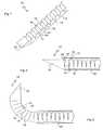
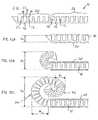
- FIG. 1is an isometric view of a first implementation of a device, constructed and operative according to the teachings of the present invention, for introduction into a body via a substantially straight conduit to form a predefined curved configuration;
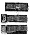
- FIG. 2is a side view of the device of FIG. 1 during insertion along a straight conduit, the conduit being cut-away for clarity of presentation;
- FIG. 3is a view similar to FIG. 2 showing the device extending beyond the straight conduit and assuming a predefined curved configuration
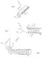
- FIG. 4is an isometric view of a second implementation of a device, constructed and operative according to the teachings of the present invention, for introduction into a body via a substantially straight conduit to form a predefined curved configuration, the device having a hollow central channel;
- FIG. 5is a side view of the device of FIG. 4 during insertion along a straight conduit, the conduit being cut-away for clarity of presentation;
- FIG. 6is a view similar to FIG. 5 showing the device extending beyond the straight conduit and assuming a predefined curved configuration
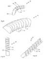
- FIG. 7is an isometric view of a third implementation of a device, constructed and operative according to the teachings of the present invention, for introduction into a body via a substantially straight conduit to form a predefined curved configuration, the device having a circular cross-sectional shape;
- FIG. 8is an isometric view of a fourth implementation of a device, constructed and operative according to the teachings of the present invention, for introduction into a body via a substantially straight conduit to form a predefined curved configuration, the device having a semicircular cross-sectional shape;
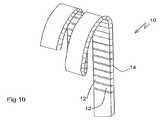
- FIG. 9Ais a front view of a fifth implementation of a device, constructed and operative according to the teachings of the present invention, for introduction into a body via a substantially straight conduit to form a predefined curved configuration, the device having oblique effective hinges between adjacent segments;
- FIG. 9Bis an isometric view of the device of FIG. 9A ;
- FIG. 10is a view similar to FIG. 9A showing the device in its predefined curved configuration
- FIG. 11is a side view of a sixth implementation of a device, constructed and operative according to the teachings of the present invention, for introduction into a body via a substantially straight conduit to form a predefined curved configuration, the device having a first region configured to produce a predefined curved configuration with a first radius of curvature and a second region configured to produce a predefined curved configuration with a second radius of curvature;
- FIGS. 12A , 12 B and 12 Care side views of the device of FIG. 11 at three stages during insertion along a straight conduit, the conduit being cut-away for clarity of presentation;
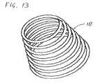
- FIG. 13is an isometric view of a seventh implementation of a device, constructed and operative according to the teachings of the present invention, for introduction into a body via a substantially straight conduit to form a predefined curved configuration, the device having a predefined shape corresponding to a conical helix;
- FIG. 14is a front view of an eighth implementation of a device, constructed and operative according to the teachings of the present invention, for introduction into a body via a substantially straight conduit to form a predefined curved configuration, the device having a predefined curved shape including both a flat spiral with a closed cylindrical helix;
- FIGS. 15A and 15Bare a partial schematic isometric view, and a partial schematic side view, of part of a device according to the present invention showing an arrangement for interlocking between adjacent segments of the device, the device being shown in its straight and curved states, respectively;
- FIGS. 16A and 16Bare a partial schematic isometric views of part of a device according to the present invention showing an alternative arrangement for interlocking between adjacent segments of the device, for a solid and hollow device, respectively;
- FIGS. 17A and 17Bare isometric cut-away views of a device according to the present invention showing an arrangement for interlocking between adjacent coils of a predefined curved shape corresponding to a closed helix;
- FIGS. 18A and 18Bare schematic partial side views of a device according to the present invention in its predefined curved shape and its straightened shape, respectively, showing an implementation of hinged interconnection for an arbitrarily curved shape;
- FIGS. 19A-19Care schematic isometric, longitudinal cross-sectional and end views, respectively, of an individual segment for use in a further implementation of a device according to the teachings of the present invention.
- FIGS. 19D and 19Eare schematic longitudinal cross-sectional views of a device formed from a plurality of the segments of FIGS. 19A-19C , the device being shown in its straightened state and predefined curved shape, respectively;
- FIG. 20Ais a schematic side view of components of a drill assembly, constructed and operative according to the teachings of the present invention.
- FIG. 20Bis a schematic side view of the drill assembly of FIG. 20A assembled
- FIG. 20Cis a schematic cross-sectional view through the drill assembly of FIG. 20B ;
- FIGS. 21A and 21Bare schematic side views, taken at orthogonal angles, illustrating the operation of the drill assembly of FIG. 20A ;
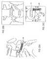
- FIGS. 22A-22Care schematic illustrations of an implementation of the present invention for posterior cervical bone anchoring using quadru-cortical bone engagement
- FIGS. 23A-23Care schematic illustrations of an implementation of the present invention for anterior cervical bone anchoring using quadru-cortical bone engagement
- FIG. 24is a schematic illustration of an implementation of the present invention for inter-vertebral disc reinforcement
- FIGS. 25A-25Care schematic lateral, anterior and axial views, respectively, showing an implementation of the present invention for inter-vertebral disc replacement
- FIG. 26Ais a schematic lateral view showing an implementation of the present invention for inter-vertebral disc replacement with adjustable height restoration
- FIGS. 26B and 26Care axial cross-sectional views taken along lines B-B and C-C, respectively, in FIG. 26A ;
- FIGS. 27A-27Care schematic posterior views of two adjacent vertebrae during progressive correction of scoliosis as a minimally invasive procedure according to the present invention.
- FIGS. 28A-28Care schematic sagittal cross-sectional views illustrating three variant implementations of multiple-segment vertebral body reinforcement according to the present invention.
- FIG. 29Ais a sagittal cross-sectional view illustrating a spinal column with healthy vertebrae
- FIG. 29Bis a view similar to FIG. 29A illustrating a collapsed vertebra
- FIG. 29Cis a view of the spinal column of FIG. 29B illustrating schematically the restoration of vertebral height according to the teachings of the present invention.
- the present inventionis a device for introduction into a body via a substantially straight conduit to form a predefined curved configuration, and methods employing such a device.
- the present inventionprovides a family of devices all based on a common inventive concept but varying in their specific implementations, and most notably, in the specific predefined curved form which the devices are configured to assume when they are inserted into a body.
- the devicesare defined geometrically by their structure, and mechanically by their properties, but are not limited to use in any specific field of technology or any specific application. These devices will be described below with reference to FIGS. 1-19E . Then, with reference to FIGS. 20A-29C , a small number of exemplary applications employing these devices will be presented, primarily in the field of medical treatment of the human body.
- FIGS. 1-3show a first basic illustration of a device, constructed and operative according to the teachings of the present invention, for introduction into a body via a substantially straight conduit 20 , and assuming within the body a predefined curved configuration.
- the device of each embodiment of the present inventionincludes an elongated element 10 formed primarily from a plurality of segments 12 sequentially interconnected so as to form an effective hinge 14 between adjacent segments 12 .
- Segments 12 and effective hinges 14are configured such that: (a) when the elongated element 10 is confined to a substantially straight state, effective hinges 14 transfer compressive forces from each segment 12 to the next so that the elongated element 10 can be pushed so as to advance through substantially straight conduit 20 ; and (b) when elongated element 10 is not confined to a substantially straight state, effective hinges 14 allow deflection of each segment 12 relative to adjacent segments 12 until at least one abutment surface 16 of each segments comes into abutment with at least one corresponding abutment surface 18 of each adjacent segment, thereby defining a fully flexed state of elongated element 10 corresponding to a predefined curved configuration of the elongated element.
- the device of the present inventionthus defined is capable of insertion into a body to any desired depth, since it initially follows a substantially straight path, and then deploys within the body to form a predefined curved structure in which adjacent segments are interconnected at an effective hinge and abut via at least one additional surface, thereby providing considerable mechanical stability.
- a wide range of curved or convoluted structurescan be introduced temporarily or permanently via an insertion opening which has dimensions corresponding to the cross-sectional dimensions of the elongated element making up the final shape.
- the devices of the present inventionmay thus be used for a wide range of applications including, but not limited to: forming a curved channel through a body; cutting-out a sample of material from a body; providing a curved anchoring structure within a body; joining together two parts of a body; aligning two parts of a body; forming a reinforcing structure within a body; filling a region of a body; and expanding a spacing between parts of a body.
- elongated element 10is resiliently biased so as to tend to deflect towards its predefined curved state. This may be achieved through pre-biasing of effective hinges 14 or by addition of supplementary springs or other resilient elements (not shown).
- the geometry of elongated element 10is chosen such that mechanical resistance during insertion of element 10 into a body causes deflection of the device to its curved state. According to either of the above options, flexing of the device is progressive, occurring continuously as the device is extended beyond the delivery conduit 20 .
- a selectively operable mechanism(not shown), such as one or more drawstring, may be provided for allowing a user to selectively induce deflection to the predefined curved configuration.
- the present inventioncan be used in a wide range of fields of application including, but not limited to, building, mining, industrial applications, carpentry, and medicine.
- the “body” within which the device is deployedmay be any body, including but not limited to: a human body; an animal body; wood; other biological materials; walls; furniture; minerals; and other inanimate objects.
- the dimensions, materials and other design parameters for the device of the present inventionmust be selected to render it suited to the intended application, as will be clear to one ordinarily skilled in the field of applications for which it is to be used.
- elongated element 10 as illustrated in FIG. 1is preferably formed from a single elongated rod of rectangular cross-section from which a series of transverse slots are cut to subdivide the elongated element into segments 12 .
- the relatively thin connecting bridge of material left beneath the slotsrenders the interconnections flexible, thereby providing effective hinges 14 .
- the slotsare shown here as V-shape slots, corresponding to sloped end surfaces of segments 12 .
- Other slot shapessuch as U-shaped slots, rectangular slots, and more complex shaped slots, may also be used.
- Effective hinges 14are thus integrally formed as flat connecting portions of flexible material interconnecting between adjacent segments.
- the term “flat”is used in this context to refer to the cross-sectional shape, namely, that in cross-section along the effective axis of the hinge, the thickness of the integral hinge is significantly less than its width, thereby providing a well-defined direction of flexing.
- the integral hingemay have significant length extending between segments 12 (as illustrated in certain examples below) or may have minimal length (such as illustrated here). Effective hinges 14 preferably provide resistance to relative motion of adjacent segments 12 other than the intended hinged motion, thereby avoiding unwanted torsional deformation of elongated element 10 .
- elongated element 10terminates in a beveled distal tip 22 angled so as to tend to deflect the elongated element into the fully flexed state as the elongated element advances through a medium.
- the beveled distal tip 22preferably has a leading edge on the side from which the slots are cut and a bevel surface facing away from the side of slots.
- This shapewhen advanced into a compressible or displaceable medium, tends to be deflected so as to follow a curved path, thereby bending elongated element 10 progressively towards its fully flexed curved form as it advances beyond delivery conduit 20 , as shown in FIG. 3 .
- the dimensions of the device of the present inventionare chosen according to the intended application and the required predefined curved shape which is to be formed.
- an element with a width and height of one meter or moremay be used.
- certain delicate medical applicationsmay use an elongated element with a width and height of 5 millimeters or less.
- lateral dimensions of 1-30 mmare suitable.
- elongated element 10is termed “elongated” in the sense that its length is significantly longer than both its width and its height. Most preferably, a length of elongated element 10 is at least ten times greater than each transverse dimension (height and width) of the elongated element.
- the deviceis configured to form a predefined curved configuration including an arc turning through an angle of at least 180°, and in many cases, passing through one or more complete revolutions as will be illustrated in a number of examples below.
- the materials for the device of the present inventionare also chosen according to the intended application and the mechanical and other properties which are required, and may be any suitable materials.
- various metals and metal alloysreferred to collectively as metallic materials
- various plastics and other polymer materialsare suitable.
- Other possibilitiesinclude, but are not limited to, composite materials and ceramic materials.
- biocompatibleare used, typically either metallic materials or polymers such as PEEK.
- the terms “two-dimensional” and “planar”are used to refer to the geometry of the predefined curved configuration of certain embodiments such as those of FIGS. 1-8 and 11 - 12 C, whereas the terms “three-dimensional” and “non-planar” are used to refer to the geometry of the predefined curved configuration of embodiments such as those of FIGS. 9A-10 , 13 and 14 . These terms are used to classify the nature of the curvature exhibited, i.e., that a circle or flat spiral is a “planar” geometry whereas a helix or cone is a “non-planar” geometry. Clearly, even the “planar” geometry implementations also occupy space in three dimensions due to the width of the elements.
- elongated element 10is cut from a solid rod such that each segment 12 is formed as a non-hollow block of material.
- each segment 12is formed as a non-hollow block of material.
- a first alternative implementationemploys a flexible strip as a backbone for the device to which segments 12 (separate blocks) are attached by any suitable attachment technique.
- An example of this kindis illustrated below with reference to FIGS. 19 a - 19 E.
- a second alternative implementationemploys a pivotal interlocking hinge arrangement, of a type either with or without a hinge pin, for connecting between initially separate segments 12 .
- Substantially straight conduit 20may be any suitable conduit, preferably close-fitting to the external shape of elongated element 10 in its substantially straight configuration.
- Conduit 20may be made of similar materials to elongated element 10 , or may be made from any other materials which are compatible with the intended application.
- conduit 20is the preferred example of a structure for restricting elongated element to a substantially straight configuration during a first part of insertion into a body, it should be noted that other alternatives also fall within the general scope of the present invention.
- an equivalent effectmay be achieved using a centrally deployed rail passing at least partially within elongated element 10 which restricts a part of elongated element 10 to its straight configuration.
- FIGS. 4-6show a second implementation of the device of the present invention. This implementation is generally similar to that of FIGS. 1-3 , differing in two respects, as will now be detailed.
- the slotsare formed as rectangular slots, so that the abutment surfaces 16 and 18 are only along the upper edges of the adjacent segments.
- This formhas certain advantages of simplicity of manufacture, and is also less sensitive to the presence of foreign matter between the abutment surfaces interfering with the curved configuration.
- the curved structurehas triangular lateral openings between adjacent segments which may be undesirable for certain applications.
- this implementationis formed from a hollow rod, resulting in an elongated element 10 in which each segment 12 is a hollow block of material.
- the resulting central channel through elongated element 10may be useful for a wide range of functions, including but not limited to: cutting out a sample of material from a body; excavating a volume of material from a body; insertion of a flexible tool through elongated element 10 to reach a target location within a body; delivering a quantity of fluid or other material to a target location within a body; providing a drive shaft for a drilling tool or other tool located at the distal end of elongated element 10 ; relaying illumination and/or images to/from a target location within a body; filling with cement to fix a deployed configuration of elongated element 10 ; and filling elongated element 10 with other materials for imparting desired properties to elongated element 10 or surrounding regions of a body.
- FIGS. 4-6can be fully understood by analogy with the structure and function of the implementation of FIGS. 1-3 described above.
- FIGS. 7 and 8it should be noted that elongated element 10 may be implemented with a wide range of different cross-sectional shapes.
- FIG. 7shows an implementation in which elongated element 10 is substantially circular in cross-section.
- effective hinges 14are preferably formed as integral hinges by leaving a portion corresponding to a chord of the circle bridging between adjacent segments 12 .
- FIG. 8shows an implementation in which elongated element 10 is substantially semi-circular.
- Effective hinges 14 interconnecting segments 12are preferably formed at the flat side of the elongated element.
- FIGS. 9A , 9 B and 10illustrate an implementation of the device of the present invention generally similar to that of FIGS. 1-3 but wherein the predefined curved configuration is a helix.
- the slots between adjacent segments 12and therefore the axes of effective hinges 14 , are at an oblique angle relative to a direction of elongation of elongated element 10 .
- angle ⁇denotes the inclination of the effective hinge axes relative to a line perpendicular to the direction of extension of elongated element 10 .
- this oblique angle of the effective hinges 14is that the predefined curved configuration includes a lateral component of curvature, thereby forming a helix as shown in FIG. 10 .
- Varying angle of inclination avaries the pitch of the helix, so that the helix can be designed to be either open as shown (i.e., with space between adjacent coils of the helix) or closed (i.e., where adjacent coils touch each other).
- FIG. 11illustrates an elongated element 10 which produces a predefined curved configuration (visible in FIG. 12C ) including a first region 24 having a first radius of curvature R 1 and a second region 26 having a second radius of curvature R 2 greater than R 1 .
- the size of segments 12 and their spacingare varied between regions 24 and 26 so that a greater degree of deflection occurs between adjacent segments 12 and/or the segments are more closely spaced in region 24 .
- FIGS. 12A-12Cillustrate the sequence of deployment of the device of FIG. 11 as it is advanced from conduit 20 .
- the distal tip of elongated element 10first advances beyond conduit 20 , it occupies a height dimension h 1 corresponding substantially to the corresponding dimension of the device in its substantially straight configuration.
- the up-down dimension as illustratedis referred to here for convenience as “height” although the device can clearly be used in any orientation.
- region 24starts to assume its predefined curved configuration, thereby defining a part of a substantially circular form of diameter (and hence height) h 2 which is twice the smaller radius of curvature R 1 .
- region 26progressively extends beyond conduit 20 to form an arc of radius R 2 , and hence raising the overall height to h 3 (twice R 2 ).
- the overall effectis gradual opening of a shape which is referred to herein as a spiral.
- this effectcould be continued, for example by forming a third region of elongated element 10 with more closely spaced segments configured to provide a yet larger radius of curvature.
- spiralis used herein in its colloquial sense to refer to any shape which spirals inwards/outwards, and is not limited to a geometric spiral which is referred to herein as a “perfect spiral”.
- the spiral formed from a stepped increase in radius of curvature as described heremay be preferred due to its simplicity of manufacture. Nevertheless, it will be appreciated that it is possible to vary segment size and/or inter-segment spacing in a continuous manner to achieve a close approximation to a perfect spiral, or any other varying curvature profile desired.
- FIGS. 13 and 14it should be noted that the principles of lateral progression described above with reference to FIGS. 9A-10 and of variable curvature described above with reference to FIGS. 11-12C can be combined to achieve an effectively unlimited range of convoluted three-dimensional structures in which radius of curvature and axial progression are arbitrarily chosen according to a specific desired application.
- FIGS. 13 and 14illustrate two examples of particular importance which combine these principles.
- FIG. 13illustrates schematically a predefined curved configuration of an elongated element 10 which is formed as a conical spiral, i.e., a series of coils with sequentially increasing radius of curvature combined with axial progression.
- the variation of the radius of curvaturemay be either continuous (i.e., varying between each adjacent pair of segments) or may be varied in steps, such as every few segments, or every 90° or 180° of a coil.
- FIG. 14shows a further preferred example in which a distal part of elongated element 10 is configured to form a planar spiral 30 (similar to FIG. 12C ) and a second portion of elongated element 10 forms a helix 32 .
- helix 32is preferably a closed helix, i.e., where each coil sits in contact with the adjacent coils (referred to as “stacked coils”). This contact between coils renders the shape structurally strong so that the device can be used for lifting part of a body or separating between two parts of a body, even where considerable forces are involved.
- the presence of the planar spiral at the distal endensures that a flat surface contacts the body to be lifted, thereby avoiding heavy abrasion of the lifted body by the leading end of the elongated element.
- FIGS. 15A-17Bit will be noted that various modifications of the shape of segments 12 may be made in order to provide various forms of interlocking, thereby improving mechanical stability of the predefined curved configurations of the present invention.
- FIGS. 15A and 15Bshow one possible modification in which abutment surfaces 16 and corresponding abutment surfaces 18 are configured with interlocking features such that, in the fully flexed state of FIG. 15B , the interlocking features help resist torsional deformation of the elongated element.
- abutment surfaces 16are formed with slots 34 while complementary abutment surfaces 18 are formed with projecting ridges 36 configured for engaging slots 34 .
- FIGS. 16A and 16Billustrate the same concept implemented without sharp ridges and slots, but rather with concavely and convexly curved abutment surfaces 16 and 18 .
- FIG. 16Billustrates the same structure as FIG. 16A implemented in a hollow embodiment.
- FIGS. 17A and 17Billustrate an additional option specifically for closed helical forms such as helix 32 of FIG. 14 in order to further stabilize the resulting stack of coils.
- lateral surfaces of segments 12are formed with complementary interlocking features so as to inhibit lateral displacement of successive coils of the helix.
- these complementary interlocking featuresare implemented as such as ridges 38 and slots 40 .
- a single step or shoulder 42is provided in the example of FIG. 17B . This second option is also useful for stabilizing a closed conical spiral where the difference in radial dimensions between adjacent coils is equal to the width of the single step.
- FIGS. 18A and 18Billustrate schematically an alternative approach to implementing the device of the present invention which facilitates forming elongated elements with arbitrarily shaped predefined curved configurations in two or three dimensions, and which are biased to their curved configurations.
- an elongated elementtypically having a uniform cross-section, is first formed into the desired predefined curved configuration by known techniques. These may include wire or bar shaping techniques for metallic material, and molding or extrusion for polymer materials. For three-dimensional shapes, a round cross-section is typically preferred.
- the elongated elementis then cut to form a plurality of slits 44 from the inside of the local curvature of the element outwards and, in the case of a round cross-section, a corresponding clearance channel 46 from the opposite side of the element.
- a round bore 48is formed at the base of each slit 44 to spread stresses within the material.
- FIGS. 19A-19Ethe devices of the present invention may be implemented using a wide variety of structures for segments 12 and effective hinges 14 .
- FIGS. 19A-19Cshow an implementation of a segment 12 formed as a separate block
- FIGS. 19D and 19Eshow an elongated element 10 formed from a series of such blocks positioned in abutment along a sheet-spring element 60 .
- the sheet spring 60passes through channels 62 formed in each segment 12 , thereby aligning the segments.
- the sheet springis preferably pre-biased to a curved form so that it returns resiliently to the curved form of FIG. 19E and can be straightened to the form of FIG. 19D .
- each segment 10further features a substantially cylindrical central opening 64 , openings 64 being aligned in the elongated element to form a “hollow” element in the sense used above.
- This round central channelis particularly suited to applications such as the flexible drill shaft described below with reference to FIGS. 20A-21B .
- the inventionmay be used in any situation where it is useful to provide a structure with a predefined curved shape which can be straightened into an elongated structure for convenient delivery, such as along a conduit.
- types of application for which the present invention is usefulinclude, but are not limited to: tunneling or drilling to form a channel; extracting material; anchoring to a body; clamping together two bodies; providing a reinforcing structure; as a filler structure; as an expander; and as a medical implant.
- the devicemay form its own channel by one or more process including compacting material, displacing material, or, in the case of hollow embodiments such as in FIGS. 4-6 , cutting out a core of material which enters the hollow of the device.
- a mechanism(not shown) may be provided for mechanically advancing the device into the material.
- itmay be necessary or preferable to provide the device with active drilling capabilities.
- FIGS. 20A-21BOne configuration suitable for implementing the present invention in combination with a drill is illustrated schematically in FIGS. 20A-21B .
- FIGS. 20A-20Cshow a curve-drilling attachment, implemented according to the teachings of the present invention, for use with a conventional or slightly modified drill.
- the attachmentincludes a rotating drill element 50 formed from a rotatable drive shaft of which at least a portion 52 is flexible and which terminates in a drilling burr 54 .
- the flexible portion 52 of the shaftmay be implemented as a helical spring as shown, or as various other flexible drive element effective for transferring rotational power to the drilling burr.
- the drill element 50is located within a hollow implementation of elongated element 10 which is anchored around flexible portion 52 but does not rotate.
- Around elongated element 10is an outer conduit 56 which is urged by a spring 58 towards drilling burr 54 .
- the elongated element 10 and outer conduit 56 of the preferred embodiment shown hereare implemented with rectangular cross-sections.
- FIGS. 21A and 21Billustrate the operation of the drill attachment.
- outer conduit 56is held back, either by being too large to follow the drill element into the hole or due to a flange (not shown) located to define a straight-drilling depth.
- outer conduit 56 stops advancingsubsequent advancing of the drill element 50 allows the portion of elongated element 10 beyond the conduit to assume its predefined curved configuration, in this case an arc of a circle, thereby bending the flexible portion 52 so that drilling burr 54 follows an arcuate path as seen in FIG. 21B .
- a drill attachment and corresponding drilling methodmay be used in a wide variety of applications. For example, in household applications, arcuate drilled channels may be used for anchoring to a wall or other object. Similarly, in dental applications, this form of drilling may be important for anchoring implants within bone. Other non-limiting examples of applications will be discussed below.
- this drilling techniquecan be used for drilling more complex three-dimensional structures.
- a helical hollow elongated elementit is possible to drill a helical bore through solid material.
- Such a boremay be valuable for various applications, including but not limited to, forming a helical cooling channel for pumping a coolant within a cylindrical wall of a cylinder.
- FIGS. 22A-22C and 23 A- 23 Cillustrate a further medical application of the arcuate drilling technique of the present invention for providing bone anchoring.
- the examples illustrated in these figuresrelate to anchoring in the cervical vertebrae, which are considered highly problematic due to the lack of cancellous bone volume.
- this preferred example of the present inventionachieves effective anchoring by using four non-collinear regions of engagement which pass through cortical bone (surfaces). This mode of anchoring is referred to herein as “quadru-cortical bone engagement”. The four regions of engagement are illustrated by numbered lines in FIGS. 22A and 23A . In the case of FIGS.
- the anchoring elementmay be the elongated element 10 inserted during drilling. Alternatively, the entire drill assembly may be withdrawn and a separate anchoring element inserted in the channel.
- FIG. 24this illustrates a related technique and corresponding structure for inter-vertebral disc reinforcement.
- an elongated element 10according to the present invention passing vertically in a semicircular arc between pedicle screws 66 in vertically adjacent vertebrae.
- the properties of elongated element 10and specifically the capability of opening up toward a lower-curvature state, allow significant relative movement between vertebrae for flexion or translation.
- the opposition of the element against bending tighter than its predefined curved formprovides significant vertical load-bearing ability, thereby maintaining spacing between the vertebrae and relieving pressure from the inter-vertebral disc (not shown).
- additional resilient material 68may be incorporated into elongated element 10 so as to provide an additional cushioning effect.
- FIGS. 25A-25Cillustrate an application of a helical elongated element of the present invention as an inter-vertebral disc replacement.
- the element 10is preferably inserted via a single pedicle screw 66 to which it is fixated after insertion.
- the external footprint of the helical implantis approximately cylindrical, and is positioned with its axis directed laterally, thereby providing support between adjacent vertebrae while allowing flexion motion.
- FIGS. 26A-26Cillustrate a further preferred implementation of the present invention employing the structure of FIG. 14 for inter-vertebral disc replacement with adjustable height restoration.
- the deviceis introduced directly between the pedicles into the inter-vertebral volume, preferably previously evacuated by a discectomy.
- the distal part of the elongated elementfirst forms a flat spiral, thereby providing a non-abrasive contact surface for the upper (or lower) vertebra.
- the closed helixbegins to accumulate, gradually lifting the upper vertebra away from the lower one until the desired height restoration is achieved.
- the elongated elementis then anchored to a single pedicle screw 66 and severed to provide an anchored disc replacement.
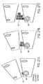
- FIGS. 27A-27Cshow schematically a minimally invasive procedure according to the present invention for progressive correction of scoliosis.
- a spiral implementation of an elongated elementis introduced through a pedicle delivery screw on the side of the spinal column where vertebral separation is required.
- the increasing diameter of the structureprogressively lifts the side of the upper vertebra away from the lower vertebra.
- This processcan be performed in parallel for a number of vertebrae. If the procedure is performed using only local anesthetic, the patient can be asked to stand between adjustments of the vertebral correction, and the adjustments can be performed iteratively until optimal correction is achieved.
- the elementsare fixated to the pedicle screw and severed, remaining as implants.
- FIGS. 28A-28Cthese illustrate the use of elongated helical implementations of the present invention as multiple-segment vertebral body reinforcements.
- an elongated element 10with a tight helical form, it is possible to introduce a reinforcing element via a single pedicle screw which will then extend vertically through the vertebral bodies and discs of multiple adjacent vertebrae. This provides reinforcement and support for the spinal column while preserving flexibility.
- the elementmay extend upwards as shown in FIG. 28A or downwards as shown in FIG. 28B . Since only one pedicle is needed for introduction of each element, it is further possible to introduce one element via a first pedicle extending upwards and second via the other pedicle extending downwards, as illustrated in FIG. 28C .
- FIGS. 29A-29Can implementation of the present invention for vertebral height restoration will now be described. Like in the height restoration for an intervertebral disc described above with reference to FIGS. 26A-26C , this aspect of the present invention is also advantageously implemented using the form of elongated element described above with reference to FIG. 14 , and in a manner analogous to that described in FIGS. 26A-26C .
- FIGS. 29A and 29Bcontrast a spinal column with healthy vertebrae against another with a collapsed vertebra.
- FIG. 29Cillustrates the spinal column of FIG. 29B after introduction of an elongated element 10 according to the teachings of the present invention.
- the black lines overlaid over the vertebrae adjacent to the collapsed vertebra of FIGS. 29B and 29Cshow clearly the vertebral height restoration achieved.
- the internal volume within the deployed elementmay be filled with suitable biocompatible material to impart additional structural or therapeutic properties.
- suitable biocompatible materialinclude, but are not limited to, bone cement, flexible biocompatible fillers and osteo-inductive agents for promoting bone growth, including bone grafts and bone marrow.
- therapeutic materials which can be introduced into the internal volumeinclude, but are not limited to, antibiotics, anti-neoplastic agents and anti-mitotic agents.
- the various hollow implementations of the elongated elementmay optionally be used for sampling tissue, such as for a biopsy, or for removing tissue, such as for a discectomy.
Landscapes
- Health & Medical Sciences (AREA)
- Orthopedic Medicine & Surgery (AREA)
- Surgery (AREA)
- Life Sciences & Earth Sciences (AREA)
- Biomedical Technology (AREA)
- Public Health (AREA)
- Veterinary Medicine (AREA)
- Engineering & Computer Science (AREA)
- Nuclear Medicine, Radiotherapy & Molecular Imaging (AREA)
- Heart & Thoracic Surgery (AREA)
- Medical Informatics (AREA)
- Molecular Biology (AREA)
- Animal Behavior & Ethology (AREA)
- General Health & Medical Sciences (AREA)
- Dentistry (AREA)
- Oral & Maxillofacial Surgery (AREA)
- Neurology (AREA)
- Prostheses (AREA)
Abstract
Description
Claims (17)
Priority Applications (1)
| Application Number | Priority Date | Filing Date | Title |
|---|---|---|---|
| US13/093,889US8486109B2 (en) | 2004-08-11 | 2011-04-26 | Devices for introduction into a body via a substantially straight conduit to form a predefined curved configuration, and methods employing such devices |
Applications Claiming Priority (7)
| Application Number | Priority Date | Filing Date | Title |
|---|---|---|---|
| US10/915,478US20060036241A1 (en) | 2004-08-11 | 2004-08-11 | Spinal surgery system and method |
| US11/028,655US7503920B2 (en) | 2004-08-11 | 2005-01-05 | Spinal surgery system and method |
| US68957005P | 2005-06-13 | 2005-06-13 | |
| PCT/IL2005/001393WO2006072941A2 (en) | 2005-01-05 | 2005-12-28 | Straight introduction device that assumes curved configuration |
| US81321307A | 2007-07-02 | 2007-07-02 | |
| US12/960,503US8236029B2 (en) | 2004-08-11 | 2010-12-05 | Devices for introduction into a body via a substantially straight conduit to for a predefined curved configuration, and methods employing such devices |
| US13/093,889US8486109B2 (en) | 2004-08-11 | 2011-04-26 | Devices for introduction into a body via a substantially straight conduit to form a predefined curved configuration, and methods employing such devices |
Related Parent Applications (1)
| Application Number | Title | Priority Date | Filing Date |
|---|---|---|---|
| US12/960,503ContinuationUS8236029B2 (en) | 2004-08-11 | 2010-12-05 | Devices for introduction into a body via a substantially straight conduit to for a predefined curved configuration, and methods employing such devices |
Publications (2)
| Publication Number | Publication Date |
|---|---|
| US20110202133A1 US20110202133A1 (en) | 2011-08-18 |
| US8486109B2true US8486109B2 (en) | 2013-07-16 |
Family
ID=46332510
Family Applications (8)
| Application Number | Title | Priority Date | Filing Date |
|---|---|---|---|
| US12/960,503Expired - Fee RelatedUS8236029B2 (en) | 2004-08-11 | 2010-12-05 | Devices for introduction into a body via a substantially straight conduit to for a predefined curved configuration, and methods employing such devices |
| US12/965,882Expired - Fee RelatedUS8241328B2 (en) | 2004-08-11 | 2010-12-12 | Devices for introduction into a body via a substantially straight conduit to form a predefined curved configuration, and methods employing such devices |
| US13/081,518Expired - Fee RelatedUS8906098B2 (en) | 2004-08-11 | 2011-04-07 | Devices for introduction into a body via a substantially straight conduit to form a predefined curved configuration, and methods employing such devices |
| US13/093,883Expired - Fee RelatedUS8206423B2 (en) | 2004-08-11 | 2011-04-26 | Devices for introduction into a body via a substantially straight conduit to form a predefined curved configuration, and methods employing such devices |
| US13/093,889Expired - Fee RelatedUS8486109B2 (en) | 2004-08-11 | 2011-04-26 | Devices for introduction into a body via a substantially straight conduit to form a predefined curved configuration, and methods employing such devices |
| US13/490,483Expired - LifetimeUS8597330B2 (en) | 2004-08-11 | 2012-06-07 | Devices for introduction into a body via a substantially straight conduit to form a predefined curved configuration, and methods employing such devices |
| US13/860,545Expired - LifetimeUS8900235B2 (en) | 2004-08-11 | 2013-04-11 | Devices for introduction into a body via a substantially straight conduit to form a predefined curved configuration, and methods employing such devices |
| US14/556,295AbandonedUS20150088139A1 (en) | 2004-08-11 | 2014-12-01 | Devices for introduction into a body via a substantially straight conduit to form a predefined curved configuration, and methods employing such devices |
Family Applications Before (4)
| Application Number | Title | Priority Date | Filing Date |
|---|---|---|---|
| US12/960,503Expired - Fee RelatedUS8236029B2 (en) | 2004-08-11 | 2010-12-05 | Devices for introduction into a body via a substantially straight conduit to for a predefined curved configuration, and methods employing such devices |
| US12/965,882Expired - Fee RelatedUS8241328B2 (en) | 2004-08-11 | 2010-12-12 | Devices for introduction into a body via a substantially straight conduit to form a predefined curved configuration, and methods employing such devices |
| US13/081,518Expired - Fee RelatedUS8906098B2 (en) | 2004-08-11 | 2011-04-07 | Devices for introduction into a body via a substantially straight conduit to form a predefined curved configuration, and methods employing such devices |
| US13/093,883Expired - Fee RelatedUS8206423B2 (en) | 2004-08-11 | 2011-04-26 | Devices for introduction into a body via a substantially straight conduit to form a predefined curved configuration, and methods employing such devices |
Family Applications After (3)
| Application Number | Title | Priority Date | Filing Date |
|---|---|---|---|
| US13/490,483Expired - LifetimeUS8597330B2 (en) | 2004-08-11 | 2012-06-07 | Devices for introduction into a body via a substantially straight conduit to form a predefined curved configuration, and methods employing such devices |
| US13/860,545Expired - LifetimeUS8900235B2 (en) | 2004-08-11 | 2013-04-11 | Devices for introduction into a body via a substantially straight conduit to form a predefined curved configuration, and methods employing such devices |
| US14/556,295AbandonedUS20150088139A1 (en) | 2004-08-11 | 2014-12-01 | Devices for introduction into a body via a substantially straight conduit to form a predefined curved configuration, and methods employing such devices |
Country Status (1)
| Country | Link |
|---|---|
| US (8) | US8236029B2 (en) |
Cited By (40)
| Publication number | Priority date | Publication date | Assignee | Title |
|---|---|---|---|---|
| US9592132B2 (en) | 2015-01-09 | 2017-03-14 | Shape Memory Orthopedics | Shape-memory spinal fusion system |
| US9662225B2 (en) | 2012-03-06 | 2017-05-30 | DePuy Synthes Products, Inc. | Nubbed plate |
| US9687354B2 (en) | 2008-03-26 | 2017-06-27 | DePuy Synthes Products, Inc. | Posterior intervertebral disc inserter and expansion techniques |
| US9713538B2 (en) | 2006-07-31 | 2017-07-25 | DePuy Synthes Products, Inc. | Spinal fusion implant |
| US9724207B2 (en) | 2003-02-14 | 2017-08-08 | DePuy Synthes Products, Inc. | In-situ formed intervertebral fusion device and method |
| US9801725B2 (en) | 2009-12-09 | 2017-10-31 | DePuy Synthes Products, Inc. | Aspirating implants and method of bony regeneration |
| US9936938B2 (en) | 2007-09-28 | 2018-04-10 | DePuy Synthes Products, Inc. | Balloon with shape control for spinal procedures |
| US9956085B2 (en) | 2005-12-23 | 2018-05-01 | DePuy Synthes Products, Inc. | Flexible elongated chain implant and method of supporting body tissue with same |
| US9993349B2 (en) | 2002-06-27 | 2018-06-12 | DePuy Synthes Products, Inc. | Intervertebral disc |
| US10182921B2 (en) | 2012-11-09 | 2019-01-22 | DePuy Synthes Products, Inc. | Interbody device with opening to allow packing graft and other biologics |
| US10206787B2 (en) | 2006-12-22 | 2019-02-19 | Medos International Sarl | Composite vertebral spacers and instrument |
| US10335289B2 (en) | 2010-09-23 | 2019-07-02 | DePuy Synthes Products, Inc. | Stand alone intervertebral fusion device |
| US10369015B2 (en) | 2010-09-23 | 2019-08-06 | DePuy Synthes Products, Inc. | Implant inserter having a laterally-extending dovetail engagement feature |
| US10433974B2 (en) | 2003-06-30 | 2019-10-08 | DePuy Synthes Products, Inc. | Intervertebral implant with conformable endplate |
| US10500062B2 (en) | 2009-12-10 | 2019-12-10 | DePuy Synthes Products, Inc. | Bellows-like expandable interbody fusion cage |
| US10624758B2 (en) | 2009-03-30 | 2020-04-21 | DePuy Synthes Products, Inc. | Zero profile spinal fusion cage |
| US10888433B2 (en) | 2016-12-14 | 2021-01-12 | DePuy Synthes Products, Inc. | Intervertebral implant inserter and related methods |
| US10940016B2 (en) | 2017-07-05 | 2021-03-09 | Medos International Sarl | Expandable intervertebral fusion cage |
| US10966840B2 (en) | 2010-06-24 | 2021-04-06 | DePuy Synthes Products, Inc. | Enhanced cage insertion assembly |
| US10973652B2 (en) | 2007-06-26 | 2021-04-13 | DePuy Synthes Products, Inc. | Highly lordosed fusion cage |
| US11273050B2 (en) | 2006-12-07 | 2022-03-15 | DePuy Synthes Products, Inc. | Intervertebral implant |
| US11344424B2 (en) | 2017-06-14 | 2022-05-31 | Medos International Sarl | Expandable intervertebral implant and related methods |
| US11426290B2 (en) | 2015-03-06 | 2022-08-30 | DePuy Synthes Products, Inc. | Expandable intervertebral implant, system, kit and method |
| US11426286B2 (en) | 2020-03-06 | 2022-08-30 | Eit Emerging Implant Technologies Gmbh | Expandable intervertebral implant |
| US11446155B2 (en) | 2017-05-08 | 2022-09-20 | Medos International Sarl | Expandable cage |
| US11446156B2 (en) | 2018-10-25 | 2022-09-20 | Medos International Sarl | Expandable intervertebral implant, inserter instrument, and related methods |
| US11452607B2 (en) | 2010-10-11 | 2022-09-27 | DePuy Synthes Products, Inc. | Expandable interspinous process spacer implant |
| US11497619B2 (en) | 2013-03-07 | 2022-11-15 | DePuy Synthes Products, Inc. | Intervertebral implant |
| US11510788B2 (en) | 2016-06-28 | 2022-11-29 | Eit Emerging Implant Technologies Gmbh | Expandable, angularly adjustable intervertebral cages |
| US11529241B2 (en) | 2010-09-23 | 2022-12-20 | DePuy Synthes Products, Inc. | Fusion cage with in-line single piece fixation |
| US11596523B2 (en) | 2016-06-28 | 2023-03-07 | Eit Emerging Implant Technologies Gmbh | Expandable and angularly adjustable articulating intervertebral cages |
| US11602438B2 (en) | 2008-04-05 | 2023-03-14 | DePuy Synthes Products, Inc. | Expandable intervertebral implant |
| US11654033B2 (en) | 2010-06-29 | 2023-05-23 | DePuy Synthes Products, Inc. | Distractible intervertebral implant |
| US11737881B2 (en) | 2008-01-17 | 2023-08-29 | DePuy Synthes Products, Inc. | Expandable intervertebral implant and associated method of manufacturing the same |
| US11752009B2 (en) | 2021-04-06 | 2023-09-12 | Medos International Sarl | Expandable intervertebral fusion cage |
| US11850160B2 (en) | 2021-03-26 | 2023-12-26 | Medos International Sarl | Expandable lordotic intervertebral fusion cage |
| US11911287B2 (en) | 2010-06-24 | 2024-02-27 | DePuy Synthes Products, Inc. | Lateral spondylolisthesis reduction cage |
| USRE49973E1 (en) | 2013-02-28 | 2024-05-21 | DePuy Synthes Products, Inc. | Expandable intervertebral implant, system, kit and method |
| US12090064B2 (en) | 2022-03-01 | 2024-09-17 | Medos International Sarl | Stabilization members for expandable intervertebral implants, and related systems and methods |
| US12440346B2 (en) | 2023-03-31 | 2025-10-14 | DePuy Synthes Products, Inc. | Expandable intervertebral implant |
Families Citing this family (44)
| Publication number | Priority date | Publication date | Assignee | Title |
|---|---|---|---|---|
| EP1713408B1 (en) | 2004-02-09 | 2010-09-15 | DePuy Spine, Inc. | Systems for spinal surgery |
| WO2006034436A2 (en) | 2004-09-21 | 2006-03-30 | Stout Medical Group, L.P. | Expandable support device and method of use |
| US8092528B2 (en) | 2005-05-27 | 2012-01-10 | Depuy Spine, Inc. | Intervertebral ligament having a helical bone fastener |
| WO2008103781A2 (en) | 2007-02-21 | 2008-08-28 | Benvenue Medical, Inc. | Devices for treating the spine |
| AU2006279558B2 (en) | 2005-08-16 | 2012-05-17 | Izi Medical Products, Llc | Spinal tissue distraction devices |
| US8366773B2 (en) | 2005-08-16 | 2013-02-05 | Benvenue Medical, Inc. | Apparatus and method for treating bone |
| EP2023864B1 (en) | 2006-05-01 | 2019-07-10 | Stout Medical Group, L.P. | Expandable support device |
| EP2124778B1 (en) | 2007-02-21 | 2019-09-25 | Benvenue Medical, Inc. | Devices for treating the spine |
| US8273124B2 (en) | 2007-05-17 | 2012-09-25 | Depuy Spine, Inc. | Self-distracting cage |
| EP2265200B1 (en)* | 2008-03-14 | 2020-05-27 | Mazor Robotics Ltd. | Segmented insert for intervertebral support |
| WO2010056895A1 (en) | 2008-11-12 | 2010-05-20 | Stout Medical Group, L.P. | Fixation device and method |
| US20100211176A1 (en) | 2008-11-12 | 2010-08-19 | Stout Medical Group, L.P. | Fixation device and method |
| US9028553B2 (en) | 2009-11-05 | 2015-05-12 | DePuy Synthes Products, Inc. | Self-pivoting spinal implant and associated instrumentation |
| WO2011149557A1 (en)* | 2010-05-27 | 2011-12-01 | Stout Medical Group, L.P. | Support device and method for use |
| EP2608747A4 (en) | 2010-08-24 | 2015-02-11 | Flexmedex Llc | Support device and method for use |
| US9220535B2 (en)* | 2010-10-26 | 2015-12-29 | Christian Röbling | Process for introducing a stabilizing element into a vertebral column |
| US9700425B1 (en) | 2011-03-20 | 2017-07-11 | Nuvasive, Inc. | Vertebral body replacement and insertion methods |
| EP3485851B1 (en) | 2011-03-22 | 2021-08-25 | DePuy Synthes Products, LLC | Universal trial for lateral cages |
| US20140012261A1 (en)* | 2012-07-09 | 2014-01-09 | Henry Nita | Ultrasound Enhanced Selective Tissue Removal Method and Apparatus |
| US8814873B2 (en) | 2011-06-24 | 2014-08-26 | Benvenue Medical, Inc. | Devices and methods for treating bone tissue |
| EP2747682A4 (en) | 2011-08-23 | 2015-01-21 | Flexmedex Llc | Tissue removal device and method |
| US9198765B1 (en) | 2011-10-31 | 2015-12-01 | Nuvasive, Inc. | Expandable spinal fusion implants and related methods |
| US9060870B2 (en) | 2012-02-05 | 2015-06-23 | Michael J. Milella, Jr. | In-situ formed spinal implant |
| US9532881B2 (en) | 2012-08-12 | 2017-01-03 | Brian Albert Hauck | Memory material implant system and methods of use |
| US9445918B1 (en) | 2012-10-22 | 2016-09-20 | Nuvasive, Inc. | Expandable spinal fusion implants and related instruments and methods |
| US10022245B2 (en) | 2012-12-17 | 2018-07-17 | DePuy Synthes Products, Inc. | Polyaxial articulating instrument |
| US10085783B2 (en) | 2013-03-14 | 2018-10-02 | Izi Medical Products, Llc | Devices and methods for treating bone tissue |
| US9572676B2 (en) | 2013-03-14 | 2017-02-21 | DePuy Synthes Products, Inc. | Adjustable multi-volume balloon for spinal interventions |
| US9358120B2 (en) | 2013-03-14 | 2016-06-07 | DePuy Synthes Products, Inc. | Expandable coil spinal implant |
| US9585761B2 (en) | 2013-03-14 | 2017-03-07 | DePuy Synthes Products, Inc. | Angulated rings and bonded foils for use with balloons for fusion and dynamic stabilization |
| US9314254B2 (en)* | 2013-03-15 | 2016-04-19 | DePuy Synthes Products, Inc. | Methods and devices for removing a spinal disc |
| US9795493B1 (en) | 2013-03-15 | 2017-10-24 | Nuvasive, Inc. | Expandable intervertebral implant and methods of use thereof |
| HK1246626A1 (en) | 2015-01-09 | 2018-09-14 | 孚美公司 | Rigid segmented flexible anchors |
| US20220183853A1 (en)* | 2015-09-04 | 2022-06-16 | Jeffrey Scott Smith | Expandable interbody fusion device for use with posterior to lateral approach |
| TWI642401B (en)* | 2017-03-03 | 2018-12-01 | 財團法人工業技術研究院 | Minimally invasive surgical device |
| CN108523961B (en)* | 2017-03-03 | 2021-01-26 | 财团法人工业技术研究院 | Minimally invasive surgical instruments |
| US10966843B2 (en) | 2017-07-18 | 2021-04-06 | DePuy Synthes Products, Inc. | Implant inserters and related methods |
| US11045331B2 (en) | 2017-08-14 | 2021-06-29 | DePuy Synthes Products, Inc. | Intervertebral implant inserters and related methods |
| US11317949B2 (en) | 2018-04-25 | 2022-05-03 | Loubert S. Suddaby | Segmented alignment rod assembly |
| US11580268B2 (en) | 2018-04-25 | 2023-02-14 | Loubert S. Suddaby | Method of creating a customized segmented alignment rod for alignment of a spine |
| US10624683B2 (en)* | 2018-04-25 | 2020-04-21 | Loubert S. Suddaby | Segmented alignment rod assembly |
| US11583323B2 (en)* | 2018-07-12 | 2023-02-21 | Treace Medical Concepts, Inc. | Multi-diameter bone pin for installing and aligning bone fixation plate while minimizing bone damage |
| SG11202108429PA (en)* | 2019-02-20 | 2021-09-29 | Edwards Lifesciences Corp | Counterflexing steerable catheter for transcatheter heart valve therapy |
| US11047249B2 (en)* | 2019-05-01 | 2021-06-29 | Raytheon Technologies Corporation | Labyrinth seal with passive check valve |
Citations (19)
| Publication number | Priority date | Publication date | Assignee | Title |
|---|---|---|---|---|
| US5285795A (en) | 1991-09-12 | 1994-02-15 | Surgical Dynamics, Inc. | Percutaneous discectomy system having a bendable discectomy probe and a steerable cannula |
| US5702454A (en) | 1993-04-21 | 1997-12-30 | Sulzer Orthopadie Ag | Process for implanting an invertebral prosthesis |
| US5756127A (en) | 1996-10-29 | 1998-05-26 | Wright Medical Technology, Inc. | Implantable bioresorbable string of calcium sulfate beads |
| US20010032017A1 (en) | 1999-12-30 | 2001-10-18 | Alfaro Arthur A. | Intervertebral implants |
| US6387130B1 (en) | 1999-04-16 | 2002-05-14 | Nuvasive, Inc. | Segmented linked intervertebral implant systems |
| US20050278023A1 (en) | 2004-06-10 | 2005-12-15 | Zwirkoski Paul A | Method and apparatus for filling a cavity |
| US7037339B2 (en) | 2001-09-27 | 2006-05-02 | Zimmer Spine, Inc. | Modular spinal fusion device |
| US7267687B2 (en) | 2001-10-02 | 2007-09-11 | Rex Medical, L.P | Spinal implant and method of use |
| US20080300601A1 (en) | 2007-05-31 | 2008-12-04 | Fabian Henry F | Spine surgery method and instrumentation |
| US20080312743A1 (en) | 2007-06-15 | 2008-12-18 | Thierry Vila | Nucleus Prostheses |
| US7547319B2 (en) | 2005-06-15 | 2009-06-16 | Ouroboros Medical | Mechanical apparatus and method for artificial disc replacement |
| US20090270873A1 (en) | 2008-04-24 | 2009-10-29 | Fabian Henry F | Spine surgery method and inserter |
| US20100185290A1 (en) | 2007-06-29 | 2010-07-22 | Curtis Compton | Flexible chain implants and instrumentation |
| US7785368B2 (en) | 2005-08-16 | 2010-08-31 | Benvenue Medical, Inc. | Spinal tissue distraction devices |
| US20110009969A1 (en) | 2009-07-09 | 2011-01-13 | Puno Rolando M | Inter-Body Implantation System and Method |
| US7905920B2 (en) | 2004-08-19 | 2011-03-15 | Foster-Miller, Inc. | Support system for intervertebral fusion |
| US7909872B2 (en) | 2005-06-03 | 2011-03-22 | Zipnick Richard I | Minimally invasive apparatus to manipulate and revitalize spinal column disc |
| US7918874B2 (en) | 2004-08-11 | 2011-04-05 | Nonlinear Technologies Ltd. | Devices for introduction into a body along a substantially straight guide to form a predefined curved configuration, and methods employing same |
| US7938860B2 (en) | 2000-08-30 | 2011-05-10 | Warsaw Orthopedic, Inc. | Intervertebral disc nucleus implants and methods |
Family Cites Families (97)
| Publication number | Priority date | Publication date | Assignee | Title |
|---|---|---|---|---|
| US5059193A (en) | 1989-11-20 | 1991-10-22 | Spine-Tech, Inc. | Expandable spinal implant and surgical method |
| US5152744A (en) | 1990-02-07 | 1992-10-06 | Smith & Nephew Dyonics | Surgical instrument |
| DE4128332A1 (en)* | 1991-08-27 | 1993-03-04 | Man Ceramics Gmbh | SPINE BONE REPLACEMENT |
| US5695913A (en)* | 1995-02-28 | 1997-12-09 | Fuji Photo Film Co., Ltd. | Process for the formation of color image |
| US5695513A (en) | 1996-03-01 | 1997-12-09 | Metagen, Llc | Flexible cutting tool and methods for its use |
| US6159214A (en) | 1996-07-31 | 2000-12-12 | Michelson; Gary K. | Milling instrumentation and method for preparing a space between adjacent vertebral bodies |
| US6190414B1 (en) | 1996-10-31 | 2001-02-20 | Surgical Dynamics Inc. | Apparatus for fusion of adjacent bone structures |
| US20080086212A1 (en) | 1997-01-02 | 2008-04-10 | St. Francis Medical Technologies, Inc. | Spine distraction implant |
| US7959652B2 (en) | 2005-04-18 | 2011-06-14 | Kyphon Sarl | Interspinous process implant having deployable wings and method of implantation |
| WO1998034552A1 (en) | 1997-02-06 | 1998-08-13 | Surgical Dynamics | Expandable non-threaded spinal fusion device |
| US6039761A (en) | 1997-02-12 | 2000-03-21 | Li Medical Technologies, Inc. | Intervertebral spacer and tool and method for emplacement thereof |
| IL128261A0 (en) | 1999-01-27 | 1999-11-30 | Disc O Tech Medical Tech Ltd | Expandable element |
| DE19710392C1 (en) | 1997-03-13 | 1999-07-01 | Haehnel Michael | Slipped disc implant comprises an extensible, hinged or wound body |
| JP3539124B2 (en) | 1997-03-27 | 2004-07-07 | 富士写真光機株式会社 | Trocar with angle mechanism |
| US7331963B2 (en) | 1997-10-06 | 2008-02-19 | Warsaw Orthopedic, Inc. | Drill head for use in placing an intervertebral disc device |
| US6126689A (en) | 1998-06-15 | 2000-10-03 | Expanding Concepts, L.L.C. | Collapsible and expandable interbody fusion device |
| US6193757B1 (en) | 1998-10-29 | 2001-02-27 | Sdgi Holdings, Inc. | Expandable intervertebral spacers |
| DE19903762C1 (en)* | 1999-01-30 | 2000-11-16 | Aesculap Ag & Co Kg | Surgical instrument for inserting intervertebral implants |
| US6607530B1 (en)* | 1999-05-10 | 2003-08-19 | Highgate Orthopedics, Inc. | Systems and methods for spinal fixation |
| US6419705B1 (en) | 1999-06-23 | 2002-07-16 | Sulzer Spine-Tech Inc. | Expandable fusion device and method |
| NL1012719C1 (en) | 1999-07-28 | 2001-01-30 | Veldhuizen Dr Ag | Spine prosthesis. |
| US6830570B1 (en) | 1999-10-21 | 2004-12-14 | Sdgi Holdings, Inc. | Devices and techniques for a posterior lateral disc space approach |
| US20030191474A1 (en) | 2000-02-16 | 2003-10-09 | Cragg Andrew H. | Apparatus for performing a discectomy through a trans-sacral axial bore within the vertebrae of the spine |
| US6641582B1 (en) | 2000-07-06 | 2003-11-04 | Sulzer Spine-Tech Inc. | Bone preparation instruments and methods |
| US6419696B1 (en)* | 2000-07-06 | 2002-07-16 | Paul A. Spence | Annuloplasty devices and related heart valve repair methods |
| US6602288B1 (en)* | 2000-10-05 | 2003-08-05 | Edwards Lifesciences Corporation | Minimally-invasive annuloplasty repair segment delivery template, system and method of use |
| US6595998B2 (en) | 2001-03-08 | 2003-07-22 | Spinewave, Inc. | Tissue distraction device |
| NL1018438C1 (en) | 2001-07-02 | 2003-01-08 | Baat Medical Engineering B V | Foldable and foldable tools for placement in a spine. |
| US6375682B1 (en) | 2001-08-06 | 2002-04-23 | Lewis W. Fleischmann | Collapsible, rotatable and expandable spinal hydraulic prosthetic device |
| EP1432369B1 (en)* | 2001-08-31 | 2008-02-27 | Mitral Interventions | Apparatus for valve repair |
| US6764510B2 (en)* | 2002-01-09 | 2004-07-20 | Myocor, Inc. | Devices and methods for heart valve treatment |
| US7087055B2 (en) | 2002-06-25 | 2006-08-08 | Sdgi Holdings, Inc. | Minimally invasive expanding spacer and method |
| US8317798B2 (en) | 2002-06-25 | 2012-11-27 | Warsaw Orthopedic | Minimally invasive expanding spacer and method |
| WO2006047598A1 (en) | 2002-09-27 | 2006-05-04 | Surgifile, Inc. | Surgical file system |
| WO2004028351A2 (en) | 2002-09-27 | 2004-04-08 | Surgifile, Inc. | Shielded reciprocating surgical file |
| EP1605836A1 (en) | 2003-03-13 | 2005-12-21 | SDGI Holdings, Inc. | Vertebral endplate preparation tool kit |
| US20040215222A1 (en) | 2003-04-25 | 2004-10-28 | Michael Krivoruchko | Intravascular material removal device |
| JP5078355B2 (en)* | 2003-05-23 | 2012-11-21 | グローバス メディカル インコーポレイティッド | Spine stabilization system |
| US7578820B2 (en) | 2003-09-02 | 2009-08-25 | Moore Jeffrey D | Devices and techniques for a minimally invasive disc space preparation and implant insertion |
| US6923813B2 (en) | 2003-09-03 | 2005-08-02 | Kyphon Inc. | Devices for creating voids in interior body regions and related methods |
| AU2004283727A1 (en) | 2003-10-23 | 2005-05-06 | Trans1 Inc. | Tools and tool kits for performing minimally invasive procedures on the spine |
| US7789912B2 (en) | 2004-01-08 | 2010-09-07 | Spine Wave, Inc. | Apparatus and method for injecting fluent material at a distracted tissue site |
| US8784421B2 (en) | 2004-03-03 | 2014-07-22 | Boston Scientific Scimed, Inc. | Apparatus and methods for removing vertebral bone and disc tissue |
| US7959634B2 (en) | 2004-03-29 | 2011-06-14 | Soteira Inc. | Orthopedic surgery access devices |
| US20050261692A1 (en) | 2004-05-21 | 2005-11-24 | Scimed Life Systems, Inc. | Articulating tissue removal probe and methods of using the same |
| FR2871366A1 (en) | 2004-06-09 | 2005-12-16 | Ceravic Soc Par Actions Simpli | PROSTHETIC EXPANSIBLE BONE IMPLANT |
| US7678148B2 (en) | 2004-07-23 | 2010-03-16 | Warsaw Orthopedic, Inc. | Expandable spinal implant having interlocking geometry for structural support |
| US7799081B2 (en) | 2004-09-14 | 2010-09-21 | Aeolin, Llc | System and method for spinal fusion |
| JP5243034B2 (en) | 2004-10-15 | 2013-07-24 | バクサノ,インク. | Tissue removal device |
| US20080103504A1 (en) | 2006-10-30 | 2008-05-01 | Schmitz Gregory P | Percutaneous spinal stenosis treatment |
| JP2008531071A (en) | 2005-01-05 | 2008-08-14 | シーガル ティゾニー | Device for introducing a predetermined curvilinear structure by being introduced into an object via a substantially straight conduit and method of using this device |
| US20060229624A1 (en) | 2005-03-31 | 2006-10-12 | Zimmer Technology, Inc. | Orthopaedic cutting instrument and method |
| US7674296B2 (en) | 2005-04-21 | 2010-03-09 | Globus Medical, Inc. | Expandable vertebral prosthesis |
| US8308802B2 (en) | 2010-01-21 | 2012-11-13 | Globus Medical, Inc. | Expandable vertebral prosthesis |
| US20070055259A1 (en) | 2005-08-17 | 2007-03-08 | Norton Britt K | Apparatus and methods for removal of intervertebral disc tissues |
| US8123750B2 (en) | 2005-08-17 | 2012-02-28 | Corespine Technologies, Llc | Apparatus and methods for removal of intervertebral disc tissues |
| US8062298B2 (en) | 2005-10-15 | 2011-11-22 | Baxano, Inc. | Flexible tissue removal devices and methods |
| US7914534B2 (en) | 2006-03-28 | 2011-03-29 | Loubert Suddaby | Disk preparation tool |
| US7842038B2 (en)* | 2006-05-04 | 2010-11-30 | Warsaw Orthopedic, Inc. | Method for using retractable stylet and cannula combination to form an opening in bone |
| US8025697B2 (en) | 2006-09-21 | 2011-09-27 | Custom Spine, Inc. | Articulating interbody spacer, vertebral body replacement |
| GB2442274A (en)* | 2006-09-29 | 2008-04-02 | Brian Eadie | Identification tag applicator with automatic release mechanism |
| US8137352B2 (en) | 2006-10-16 | 2012-03-20 | Depuy Spine, Inc. | Expandable intervertebral tool system and method |
| EP2088938A2 (en) | 2006-11-15 | 2009-08-19 | Aoi Medical, Inc. | Tissue cavitation device and method |
| US7947078B2 (en) | 2007-01-09 | 2011-05-24 | Nonlinear Technologies Ltd. | Devices for forming curved or closed-loop structures |
| EP2114257B1 (en) | 2007-02-09 | 2013-05-22 | Alphatec Spine, Inc. | Curvilinear spinal access device |
| CN101687067A (en) | 2007-02-22 | 2010-03-31 | 脊柱诊察公司 | Expandable rotating device and method for tissue aspiration |
| US8021429B2 (en) | 2007-03-08 | 2011-09-20 | Zimmer Spine, Inc. | Deployable segmented TLIF device |
| US20080243126A1 (en) | 2007-03-26 | 2008-10-02 | Robert Gutierrez | Rotary angled scraper for spinal disc space preparation |
| WO2008124650A1 (en) | 2007-04-06 | 2008-10-16 | Interlace Medical, Inc. | Method, system and device for tissue removal |
| US20090131952A1 (en) | 2007-05-21 | 2009-05-21 | Brian Schumacher | Delivery system and method for inflatable devices |
| US7967867B2 (en) | 2007-05-31 | 2011-06-28 | Spine Wave, Inc. | Expandable interbody fusion device |
| US7922767B2 (en) | 2007-07-07 | 2011-04-12 | Jmea Corporation | Disk fusion implant |
| WO2009073918A2 (en) | 2007-12-10 | 2009-06-18 | Cellixe Pty Ltd | Agent delivery device and method |
| US20090240334A1 (en) | 2008-03-19 | 2009-09-24 | Richelsoph Marc E | Vertebral device for restoration of vertebral body height |
| US8221425B2 (en) | 2008-04-30 | 2012-07-17 | Warsaw Orthopedic, Inc. | Percutaneous discectomy and endplate preparation tool |
| US8052375B2 (en) | 2008-06-02 | 2011-11-08 | General Electric Company | Fluidic sealing for turbomachinery |
| US8277506B2 (en) | 2008-06-24 | 2012-10-02 | Carefusion 2200, Inc. | Method and structure for stabilizing a vertebral body |
| US20100030216A1 (en) | 2008-07-30 | 2010-02-04 | Arcenio Gregory B | Discectomy tool having counter-rotating nucleus disruptors |
| KR20100016990A (en)* | 2008-08-05 | 2010-02-16 | 삼성전자주식회사 | Solar cell and method of manufacturing the same |
| US8147554B2 (en) | 2008-10-13 | 2012-04-03 | Globus Medical, Inc. | Intervertebral spacer |
| US8951546B2 (en) | 2008-12-23 | 2015-02-10 | Surmodics Pharmaceuticals, Inc. | Flexible implantable composites and implants comprising same |
| US8470043B2 (en) | 2008-12-23 | 2013-06-25 | Benvenue Medical, Inc. | Tissue removal tools and methods of use |
| US20100179557A1 (en) | 2009-01-15 | 2010-07-15 | Husted Daniel S | Adjustable Powered Rongeur |
| US8394101B2 (en) | 2009-02-23 | 2013-03-12 | Globus Medical, Inc. | Discectomy instrument |
| US8142463B2 (en) | 2009-03-13 | 2012-03-27 | Kyphon Sarl | Battery operated nucleus disruptor device for intervertebral disc |
| EP2408382A4 (en) | 2009-03-13 | 2013-06-19 | Univ Toledo | FOLDING CAGE LITTLE INVASIVE |
| US8292963B2 (en) | 2009-04-23 | 2012-10-23 | Warsaw Orthopedic, Inc. | Expandable implant for supporting skeletal structures |
| US20120157766A1 (en) | 2009-05-21 | 2012-06-21 | The Regents Of The University Of Michigan | Device for endoscopic treatment of upper gastrointestinal bleeding |
| EP2480143A4 (en) | 2009-09-24 | 2014-11-19 | Medicinelodge Inc Dba Imds Co Innovation | Surgical rasping systems and methods |
| US8685098B2 (en) | 2010-06-25 | 2014-04-01 | Globus Medical, Inc. | Expandable fusion device and method of installation thereof |
| WO2011060077A1 (en) | 2009-11-10 | 2011-05-19 | Spine View, Inc. | Angled grinder |
| US8506635B2 (en) | 2010-06-02 | 2013-08-13 | Warsaw Orthopedic, Inc. | System and methods for a laterally expanding implant |
| US8979860B2 (en) | 2010-06-24 | 2015-03-17 | DePuy Synthes Products. LLC | Enhanced cage insertion device |
| EP2590579B1 (en) | 2010-07-07 | 2019-08-28 | Carevature Medical Ltd. | Surgical device for tissue removal |
| US8398713B2 (en) | 2010-09-03 | 2013-03-19 | Globus Medical, Inc. | Expandable fusion device and method of installation thereof |
| US20120109186A1 (en) | 2010-10-29 | 2012-05-03 | Parrott David A | Articulating laparoscopic surgical instruments |
| US20120123546A1 (en) | 2010-11-15 | 2012-05-17 | MEDevice IP Holdings, LLC. | Implant apparatus for spinal fusion |
- 2010
- 2010-12-05USUS12/960,503patent/US8236029B2/ennot_activeExpired - Fee Related
- 2010-12-12USUS12/965,882patent/US8241328B2/ennot_activeExpired - Fee Related
- 2011
- 2011-04-07USUS13/081,518patent/US8906098B2/ennot_activeExpired - Fee Related
- 2011-04-26USUS13/093,883patent/US8206423B2/ennot_activeExpired - Fee Related
- 2011-04-26USUS13/093,889patent/US8486109B2/ennot_activeExpired - Fee Related
- 2012
- 2012-06-07USUS13/490,483patent/US8597330B2/ennot_activeExpired - Lifetime
- 2013
- 2013-04-11USUS13/860,545patent/US8900235B2/ennot_activeExpired - Lifetime
- 2014
- 2014-12-01USUS14/556,295patent/US20150088139A1/ennot_activeAbandoned
Patent Citations (19)
| Publication number | Priority date | Publication date | Assignee | Title |
|---|---|---|---|---|
| US5285795A (en) | 1991-09-12 | 1994-02-15 | Surgical Dynamics, Inc. | Percutaneous discectomy system having a bendable discectomy probe and a steerable cannula |
| US5702454A (en) | 1993-04-21 | 1997-12-30 | Sulzer Orthopadie Ag | Process for implanting an invertebral prosthesis |
| US5756127A (en) | 1996-10-29 | 1998-05-26 | Wright Medical Technology, Inc. | Implantable bioresorbable string of calcium sulfate beads |
| US6387130B1 (en) | 1999-04-16 | 2002-05-14 | Nuvasive, Inc. | Segmented linked intervertebral implant systems |
| US20010032017A1 (en) | 1999-12-30 | 2001-10-18 | Alfaro Arthur A. | Intervertebral implants |
| US7938860B2 (en) | 2000-08-30 | 2011-05-10 | Warsaw Orthopedic, Inc. | Intervertebral disc nucleus implants and methods |
| US7037339B2 (en) | 2001-09-27 | 2006-05-02 | Zimmer Spine, Inc. | Modular spinal fusion device |
| US7267687B2 (en) | 2001-10-02 | 2007-09-11 | Rex Medical, L.P | Spinal implant and method of use |
| US20050278023A1 (en) | 2004-06-10 | 2005-12-15 | Zwirkoski Paul A | Method and apparatus for filling a cavity |
| US7918874B2 (en) | 2004-08-11 | 2011-04-05 | Nonlinear Technologies Ltd. | Devices for introduction into a body along a substantially straight guide to form a predefined curved configuration, and methods employing same |
| US7905920B2 (en) | 2004-08-19 | 2011-03-15 | Foster-Miller, Inc. | Support system for intervertebral fusion |
| US7909872B2 (en) | 2005-06-03 | 2011-03-22 | Zipnick Richard I | Minimally invasive apparatus to manipulate and revitalize spinal column disc |
| US7547319B2 (en) | 2005-06-15 | 2009-06-16 | Ouroboros Medical | Mechanical apparatus and method for artificial disc replacement |
| US7785368B2 (en) | 2005-08-16 | 2010-08-31 | Benvenue Medical, Inc. | Spinal tissue distraction devices |
| US20080300601A1 (en) | 2007-05-31 | 2008-12-04 | Fabian Henry F | Spine surgery method and instrumentation |
| US20080312743A1 (en) | 2007-06-15 | 2008-12-18 | Thierry Vila | Nucleus Prostheses |
| US20100185290A1 (en) | 2007-06-29 | 2010-07-22 | Curtis Compton | Flexible chain implants and instrumentation |
| US20090270873A1 (en) | 2008-04-24 | 2009-10-29 | Fabian Henry F | Spine surgery method and inserter |
| US20110009969A1 (en) | 2009-07-09 | 2011-01-13 | Puno Rolando M | Inter-Body Implantation System and Method |
Cited By (108)
| Publication number | Priority date | Publication date | Assignee | Title |
|---|---|---|---|---|
| US9993349B2 (en) | 2002-06-27 | 2018-06-12 | DePuy Synthes Products, Inc. | Intervertebral disc |
| US10238500B2 (en) | 2002-06-27 | 2019-03-26 | DePuy Synthes Products, Inc. | Intervertebral disc |
| US11207187B2 (en) | 2003-02-14 | 2021-12-28 | DePuy Synthes Products, Inc. | In-situ formed intervertebral fusion device and method |
| US10639164B2 (en) | 2003-02-14 | 2020-05-05 | DePuy Synthes Products, Inc. | In-situ formed intervertebral fusion device and method |
| US10376372B2 (en) | 2003-02-14 | 2019-08-13 | DePuy Synthes Products, Inc. | In-situ formed intervertebral fusion device and method |
| US9724207B2 (en) | 2003-02-14 | 2017-08-08 | DePuy Synthes Products, Inc. | In-situ formed intervertebral fusion device and method |
| US10492918B2 (en) | 2003-02-14 | 2019-12-03 | DePuy Synthes Products, Inc. | In-situ formed intervertebral fusion device and method |
| US10555817B2 (en) | 2003-02-14 | 2020-02-11 | DePuy Synthes Products, Inc. | In-situ formed intervertebral fusion device and method |
| US9788963B2 (en) | 2003-02-14 | 2017-10-17 | DePuy Synthes Products, Inc. | In-situ formed intervertebral fusion device and method |
| US10420651B2 (en) | 2003-02-14 | 2019-09-24 | DePuy Synthes Products, Inc. | In-situ formed intervertebral fusion device and method |
| US9801729B2 (en) | 2003-02-14 | 2017-10-31 | DePuy Synthes Products, Inc. | In-situ formed intervertebral fusion device and method |
| US9808351B2 (en) | 2003-02-14 | 2017-11-07 | DePuy Synthes Products, Inc. | In-situ formed intervertebral fusion device and method |
| US9814589B2 (en) | 2003-02-14 | 2017-11-14 | DePuy Synthes Products, Inc. | In-situ formed intervertebral fusion device and method |
| US9814590B2 (en) | 2003-02-14 | 2017-11-14 | DePuy Synthes Products, Inc. | In-situ formed intervertebral fusion device and method |
| US10433971B2 (en) | 2003-02-14 | 2019-10-08 | DePuy Synthes Products, Inc. | In-situ formed intervertebral fusion device and method |
| US9925060B2 (en) | 2003-02-14 | 2018-03-27 | DePuy Synthes Products, Inc. | In-situ formed intervertebral fusion device and method |
| US11096794B2 (en) | 2003-02-14 | 2021-08-24 | DePuy Synthes Products, Inc. | In-situ formed intervertebral fusion device and method |
| US9730803B2 (en) | 2003-02-14 | 2017-08-15 | DePuy Synthes Products, Inc. | Method of in-situ formation of an intervertebral fusion device |
| US10575959B2 (en) | 2003-02-14 | 2020-03-03 | DePuy Synthes Products, Inc. | In-situ formed intervertebral fusion device and method |
| US10786361B2 (en) | 2003-02-14 | 2020-09-29 | DePuy Synthes Products, Inc. | In-situ formed intervertebral fusion device and method |
| US10085843B2 (en) | 2003-02-14 | 2018-10-02 | DePuy Synthes Products, Inc. | In-situ formed intervertebral fusion device and method |
| US10405986B2 (en) | 2003-02-14 | 2019-09-10 | DePuy Synthes Products, Inc. | In-situ formed intervertebral fusion device and method |
| US10583013B2 (en) | 2003-02-14 | 2020-03-10 | DePuy Synthes Products, Inc. | In-situ formed intervertebral fusion device and method |
| US11432938B2 (en) | 2003-02-14 | 2022-09-06 | DePuy Synthes Products, Inc. | In-situ intervertebral fusion device and method |
| US10433974B2 (en) | 2003-06-30 | 2019-10-08 | DePuy Synthes Products, Inc. | Intervertebral implant with conformable endplate |
| US11612493B2 (en) | 2003-06-30 | 2023-03-28 | DePuy Synthes Products, Inc. | Intervertebral implant with conformable endplate |
| US10881520B2 (en) | 2005-12-23 | 2021-01-05 | DePuy Synthes Products, Inc. | Flexible elongated chain implant and method of supporting body tissue with same |
| US9956085B2 (en) | 2005-12-23 | 2018-05-01 | DePuy Synthes Products, Inc. | Flexible elongated chain implant and method of supporting body tissue with same |
| US11406508B2 (en) | 2005-12-23 | 2022-08-09 | DePuy Synthes Products, Inc. | Flexible elongated chain implant and method of supporting body tissue with same |
| US11701233B2 (en) | 2005-12-23 | 2023-07-18 | DePuy Synthes Products, Inc. | Flexible elongated chain implant and method of supporting body tissue with same |
| US10010428B2 (en) | 2006-07-31 | 2018-07-03 | DePuy Synthes Products, Inc. | Spinal fusion implant |
| US9737413B2 (en) | 2006-07-31 | 2017-08-22 | DePuy Synthes Products, Inc. | Spinal fusion implant |
| US9713538B2 (en) | 2006-07-31 | 2017-07-25 | DePuy Synthes Products, Inc. | Spinal fusion implant |
| US10695191B2 (en) | 2006-07-31 | 2020-06-30 | DePuy Synthes Products, Inc. | Spinal fusion implant |
| US11432942B2 (en) | 2006-12-07 | 2022-09-06 | DePuy Synthes Products, Inc. | Intervertebral implant |
| US11642229B2 (en) | 2006-12-07 | 2023-05-09 | DePuy Synthes Products, Inc. | Intervertebral implant |
| US11660206B2 (en) | 2006-12-07 | 2023-05-30 | DePuy Synthes Products, Inc. | Intervertebral implant |
| US11497618B2 (en) | 2006-12-07 | 2022-11-15 | DePuy Synthes Products, Inc. | Intervertebral implant |
| US11273050B2 (en) | 2006-12-07 | 2022-03-15 | DePuy Synthes Products, Inc. | Intervertebral implant |
| US11712345B2 (en) | 2006-12-07 | 2023-08-01 | DePuy Synthes Products, Inc. | Intervertebral implant |
| US11020237B2 (en) | 2006-12-22 | 2021-06-01 | Medos International Sarl | Composite vertebral spacers and instrument |
| US10206787B2 (en) | 2006-12-22 | 2019-02-19 | Medos International Sarl | Composite vertebral spacers and instrument |
| US10973652B2 (en) | 2007-06-26 | 2021-04-13 | DePuy Synthes Products, Inc. | Highly lordosed fusion cage |
| US11622868B2 (en) | 2007-06-26 | 2023-04-11 | DePuy Synthes Products, Inc. | Highly lordosed fusion cage |
| US12426868B2 (en) | 2007-09-28 | 2025-09-30 | DePuy Synthes Products, Inc. | Balloon with shape control for spinal procedures |
| US10786231B2 (en) | 2007-09-28 | 2020-09-29 | DePuy Synthes Products, Inc. | Balloon with shape control for spinal procedures |
| US9936938B2 (en) | 2007-09-28 | 2018-04-10 | DePuy Synthes Products, Inc. | Balloon with shape control for spinal procedures |
| US11737881B2 (en) | 2008-01-17 | 2023-08-29 | DePuy Synthes Products, Inc. | Expandable intervertebral implant and associated method of manufacturing the same |
| US9687354B2 (en) | 2008-03-26 | 2017-06-27 | DePuy Synthes Products, Inc. | Posterior intervertebral disc inserter and expansion techniques |
| US10206784B2 (en) | 2008-03-26 | 2019-02-19 | DePuy Synthes Products, Inc. | Posterior intervertebral disc inserter and expansion techniques |
| US12023255B2 (en) | 2008-04-05 | 2024-07-02 | DePuy Synthes Products, Inc. | Expandable inter vertebral implant |
| US11712342B2 (en) | 2008-04-05 | 2023-08-01 | DePuy Synthes Products, Inc. | Expandable intervertebral implant |
| US11602438B2 (en) | 2008-04-05 | 2023-03-14 | DePuy Synthes Products, Inc. | Expandable intervertebral implant |
| US11712341B2 (en) | 2008-04-05 | 2023-08-01 | DePuy Synthes Products, Inc. | Expandable intervertebral implant |
| US11707359B2 (en) | 2008-04-05 | 2023-07-25 | DePuy Synthes Products, Inc. | Expandable intervertebral implant |
| US11701234B2 (en) | 2008-04-05 | 2023-07-18 | DePuy Synthes Products, Inc. | Expandable intervertebral implant |
| US11617655B2 (en) | 2008-04-05 | 2023-04-04 | DePuy Synthes Products, Inc. | Expandable intervertebral implant |
| US12011361B2 (en) | 2008-04-05 | 2024-06-18 | DePuy Synthes Products, Inc. | Expandable intervertebral implant |
| US11612491B2 (en) | 2009-03-30 | 2023-03-28 | DePuy Synthes Products, Inc. | Zero profile spinal fusion cage |
| US12097124B2 (en) | 2009-03-30 | 2024-09-24 | DePuy Synthes Products, Inc. | Zero profile spinal fusion cage |
| US10624758B2 (en) | 2009-03-30 | 2020-04-21 | DePuy Synthes Products, Inc. | Zero profile spinal fusion cage |
| US9801725B2 (en) | 2009-12-09 | 2017-10-31 | DePuy Synthes Products, Inc. | Aspirating implants and method of bony regeneration |
| US10342662B2 (en) | 2009-12-09 | 2019-07-09 | DePuy Synthes Products, Inc. | Aspirating implants and method of bony regeneration |
| US10500062B2 (en) | 2009-12-10 | 2019-12-10 | DePuy Synthes Products, Inc. | Bellows-like expandable interbody fusion cage |
| US11607321B2 (en) | 2009-12-10 | 2023-03-21 | DePuy Synthes Products, Inc. | Bellows-like expandable interbody fusion cage |
| US11911287B2 (en) | 2010-06-24 | 2024-02-27 | DePuy Synthes Products, Inc. | Lateral spondylolisthesis reduction cage |
| US11872139B2 (en) | 2010-06-24 | 2024-01-16 | DePuy Synthes Products, Inc. | Enhanced cage insertion assembly |
| US12318304B2 (en) | 2010-06-24 | 2025-06-03 | DePuy Synthes Products, Inc. | Lateral spondylolisthesis reduction cage |
| US10966840B2 (en) | 2010-06-24 | 2021-04-06 | DePuy Synthes Products, Inc. | Enhanced cage insertion assembly |
| US11654033B2 (en) | 2010-06-29 | 2023-05-23 | DePuy Synthes Products, Inc. | Distractible intervertebral implant |
| US10335289B2 (en) | 2010-09-23 | 2019-07-02 | DePuy Synthes Products, Inc. | Stand alone intervertebral fusion device |
| US10369015B2 (en) | 2010-09-23 | 2019-08-06 | DePuy Synthes Products, Inc. | Implant inserter having a laterally-extending dovetail engagement feature |
| US11529241B2 (en) | 2010-09-23 | 2022-12-20 | DePuy Synthes Products, Inc. | Fusion cage with in-line single piece fixation |
| US12109127B2 (en) | 2010-09-23 | 2024-10-08 | DePuy Synthes Products, Inc. | Implant inserter having a laterally-extending dovetail engagement feature |
| US11382768B2 (en) | 2010-09-23 | 2022-07-12 | DePuy Synthes Products, Inc. | Implant inserter having a laterally-extending dovetail engagement feature |
| US11678996B2 (en) | 2010-09-23 | 2023-06-20 | DePuy Synthes Products, Inc. | Stand alone intervertebral fusion device |
| US11452607B2 (en) | 2010-10-11 | 2022-09-27 | DePuy Synthes Products, Inc. | Expandable interspinous process spacer implant |
| US9662225B2 (en) | 2012-03-06 | 2017-05-30 | DePuy Synthes Products, Inc. | Nubbed plate |
| US11844702B2 (en) | 2012-03-06 | 2023-12-19 | DePuy Synthes Products, Inc. | Nubbed plate |
| US9872781B2 (en) | 2012-03-06 | 2018-01-23 | DePuy Synthes Products, Inc. | Nubbed plate |
| US9668877B2 (en) | 2012-03-06 | 2017-06-06 | DePuy Synthes Products, Inc. | Nubbed plate |
| US11071634B2 (en) | 2012-03-06 | 2021-07-27 | DePuy Synthes Products, Inc. | Nubbed plate |
| US10327915B2 (en) | 2012-03-06 | 2019-06-25 | DePuy Synthes Products, Inc. | Nubbed plate |
| US11497616B2 (en) | 2012-11-09 | 2022-11-15 | DePuy Synthes Products, Inc. | Interbody device with opening to allow packing graft and other biologics |
| US10182921B2 (en) | 2012-11-09 | 2019-01-22 | DePuy Synthes Products, Inc. | Interbody device with opening to allow packing graft and other biologics |
| USRE49973E1 (en) | 2013-02-28 | 2024-05-21 | DePuy Synthes Products, Inc. | Expandable intervertebral implant, system, kit and method |
| US11497619B2 (en) | 2013-03-07 | 2022-11-15 | DePuy Synthes Products, Inc. | Intervertebral implant |
| US11850164B2 (en) | 2013-03-07 | 2023-12-26 | DePuy Synthes Products, Inc. | Intervertebral implant |
| US9592132B2 (en) | 2015-01-09 | 2017-03-14 | Shape Memory Orthopedics | Shape-memory spinal fusion system |
| US11426290B2 (en) | 2015-03-06 | 2022-08-30 | DePuy Synthes Products, Inc. | Expandable intervertebral implant, system, kit and method |
| US11596523B2 (en) | 2016-06-28 | 2023-03-07 | Eit Emerging Implant Technologies Gmbh | Expandable and angularly adjustable articulating intervertebral cages |
| US11596522B2 (en) | 2016-06-28 | 2023-03-07 | Eit Emerging Implant Technologies Gmbh | Expandable and angularly adjustable intervertebral cages with articulating joint |
| US11510788B2 (en) | 2016-06-28 | 2022-11-29 | Eit Emerging Implant Technologies Gmbh | Expandable, angularly adjustable intervertebral cages |
| US12390343B2 (en) | 2016-06-28 | 2025-08-19 | Eit Emerging Implant Technologies Gmbh | Expandable, angularly adjustable intervertebral cages |
| US12433757B2 (en) | 2016-06-28 | 2025-10-07 | Eit Emerging Implant Technologies Gmbh | Expandable, angularly adjustable and articulating intervertebral cages |
| US10888433B2 (en) | 2016-12-14 | 2021-01-12 | DePuy Synthes Products, Inc. | Intervertebral implant inserter and related methods |
| US12427031B2 (en) | 2017-05-08 | 2025-09-30 | Medos International Sarl | Expandable cage |
| US11446155B2 (en) | 2017-05-08 | 2022-09-20 | Medos International Sarl | Expandable cage |
| US11344424B2 (en) | 2017-06-14 | 2022-05-31 | Medos International Sarl | Expandable intervertebral implant and related methods |
| US10940016B2 (en) | 2017-07-05 | 2021-03-09 | Medos International Sarl | Expandable intervertebral fusion cage |
| US11446156B2 (en) | 2018-10-25 | 2022-09-20 | Medos International Sarl | Expandable intervertebral implant, inserter instrument, and related methods |
| US11806245B2 (en) | 2020-03-06 | 2023-11-07 | Eit Emerging Implant Technologies Gmbh | Expandable intervertebral implant |
| US11426286B2 (en) | 2020-03-06 | 2022-08-30 | Eit Emerging Implant Technologies Gmbh | Expandable intervertebral implant |
| US11850160B2 (en) | 2021-03-26 | 2023-12-26 | Medos International Sarl | Expandable lordotic intervertebral fusion cage |
| US12023258B2 (en) | 2021-04-06 | 2024-07-02 | Medos International Sarl | Expandable intervertebral fusion cage |
| US11752009B2 (en) | 2021-04-06 | 2023-09-12 | Medos International Sarl | Expandable intervertebral fusion cage |
| US12090064B2 (en) | 2022-03-01 | 2024-09-17 | Medos International Sarl | Stabilization members for expandable intervertebral implants, and related systems and methods |
| US12440346B2 (en) | 2023-03-31 | 2025-10-14 | DePuy Synthes Products, Inc. | Expandable intervertebral implant |
Also Published As
| Publication number | Publication date |
|---|---|
| US20110118789A1 (en) | 2011-05-19 |
| US8236029B2 (en) | 2012-08-07 |
| US8206423B2 (en) | 2012-06-26 |
| US20110153019A1 (en) | 2011-06-23 |
| US8900235B2 (en) | 2014-12-02 |
| US8597330B2 (en) | 2013-12-03 |
| US20120245570A1 (en) | 2012-09-27 |
| US20110264146A1 (en) | 2011-10-27 |
| US8241328B2 (en) | 2012-08-14 |
| US20130289568A1 (en) | 2013-10-31 |
| US20150088139A1 (en) | 2015-03-26 |
| US20110202133A1 (en) | 2011-08-18 |
| US8906098B2 (en) | 2014-12-09 |
| US20110184515A1 (en) | 2011-07-28 |
Similar Documents
| Publication | Publication Date | Title |
|---|---|---|
| US8486109B2 (en) | Devices for introduction into a body via a substantially straight conduit to form a predefined curved configuration, and methods employing such devices | |
| US8465524B2 (en) | Devices for introduction into a body via a substantially straight conduit to form a predefined curved configuration, and methods employing such devices | |
| EP2633829B1 (en) | Device for introduction into a body along a substantially straight elongated-element-restricting structure | |
| US7918874B2 (en) | Devices for introduction into a body along a substantially straight guide to form a predefined curved configuration, and methods employing same | |
| US11992417B2 (en) | Flexible anchoring and fusion devices and methods of using the same | |
| US8579903B2 (en) | Devices and methods for stabilizing a spinal region | |
| JP6072704B2 (en) | Method and apparatus for minimally invasive insertion of an intervertebral implant | |
| US20060276790A1 (en) | Minimally invasive facet joint repair | |
| US20080228192A1 (en) | Cannula | |
| JP2008531071A (en) | Device for introducing a predetermined curvilinear structure by being introduced into an object via a substantially straight conduit and method of using this device | |
| IL183156A (en) | Devices for introduction into a body via a substantially straight conduit to form a predefined curved configuration and methods employing such devices |
Legal Events
| Date | Code | Title | Description |
|---|---|---|---|
| STCF | Information on status: patent grant | Free format text:PATENTED CASE | |
| FPAY | Fee payment | Year of fee payment:4 | |
| AS | Assignment | Owner name:NONLINEAR TECHNOLOGIES LTD., ISRAEL Free format text:ASSIGNMENT OF ASSIGNORS INTEREST;ASSIGNOR:SIEGAL, TZONY, DR.;REEL/FRAME:046946/0940 Effective date:20090215 Owner name:SEASPINE, INC., CALIFORNIA Free format text:ASSIGNMENT OF ASSIGNORS INTEREST;ASSIGNOR:NLT SPINE LTD.;REEL/FRAME:046946/0960 Effective date:20180508 Owner name:NLT SPINE LTD., ISRAEL Free format text:CHANGE OF NAME;ASSIGNOR:NONLINEAR TECHNOLOGIES LTD.;REEL/FRAME:047129/0401 Effective date:20120117 | |
| MAFP | Maintenance fee payment | Free format text:PAYMENT OF MAINTENANCE FEE, 8TH YR, SMALL ENTITY (ORIGINAL EVENT CODE: M2552); ENTITY STATUS OF PATENT OWNER: SMALL ENTITY Year of fee payment:8 | |
| AS | Assignment | Owner name:WELLS FARGO BANK, NATIONAL ASSOCIATION, CALIFORNIA Free format text:SECURITY INTEREST;ASSIGNORS:SEASPINE HOLDINGS CORPORATION;SEASPINE ORTHOPEDICS CORPORATION;SEASPINE, INC.;AND OTHERS;REEL/FRAME:057941/0609 Effective date:20211026 | |
| AS | Assignment | Owner name:WELLS FARGO BANK, NATIONAL ASSOCIATION, AS AGENT, CALIFORNIA Free format text:SECOND AMENDMENT TO PATENT SECURITY AGREEMENT;ASSIGNORS:SEASPINE HOLDINGS CORPORATION;SEASPINE ORTHOPEDICS CORPORATION;SEASPINE, INC.;AND OTHERS;REEL/FRAME:060715/0395 Effective date:20220715 | |
| AS | Assignment | Owner name:7D SURGICAL USA INC., CALIFORNIA Free format text:RELEASE BY SECURED PARTY;ASSIGNOR:WELLS FARGO BANK, NATIONAL ASSOCIATION;REEL/FRAME:062336/0593 Effective date:20230105 Owner name:SEASPINE ORTHOPEDICS INTERMEDIATECO, INC., CALIFORNIA Free format text:RELEASE BY SECURED PARTY;ASSIGNOR:WELLS FARGO BANK, NATIONAL ASSOCIATION;REEL/FRAME:062336/0593 Effective date:20230105 Owner name:THEKEN SPINE, LLC, CALIFORNIA Free format text:RELEASE BY SECURED PARTY;ASSIGNOR:WELLS FARGO BANK, NATIONAL ASSOCIATION;REEL/FRAME:062336/0593 Effective date:20230105 Owner name:ISOTIS ORTHOBIOLOGICS, INC., CALIFORNIA Free format text:RELEASE BY SECURED PARTY;ASSIGNOR:WELLS FARGO BANK, NATIONAL ASSOCIATION;REEL/FRAME:062336/0593 Effective date:20230105 Owner name:SEASPINE SALES LLC, CALIFORNIA Free format text:RELEASE BY SECURED PARTY;ASSIGNOR:WELLS FARGO BANK, NATIONAL ASSOCIATION;REEL/FRAME:062336/0593 Effective date:20230105 Owner name:ISOTIS, INC., CALIFORNIA Free format text:RELEASE BY SECURED PARTY;ASSIGNOR:WELLS FARGO BANK, NATIONAL ASSOCIATION;REEL/FRAME:062336/0593 Effective date:20230105 Owner name:SEASPINE, INC., CALIFORNIA Free format text:RELEASE BY SECURED PARTY;ASSIGNOR:WELLS FARGO BANK, NATIONAL ASSOCIATION;REEL/FRAME:062336/0593 Effective date:20230105 Owner name:SEASPINE ORTHOPEDICS CORPORATION, CALIFORNIA Free format text:RELEASE BY SECURED PARTY;ASSIGNOR:WELLS FARGO BANK, NATIONAL ASSOCIATION;REEL/FRAME:062336/0593 Effective date:20230105 Owner name:SEASPINE HOLDINGS CORPORATION, CALIFORNIA Free format text:RELEASE BY SECURED PARTY;ASSIGNOR:WELLS FARGO BANK, NATIONAL ASSOCIATION;REEL/FRAME:062336/0593 Effective date:20230105 | |
| AS | Assignment | Owner name:JPMORGAN CHASE BANK, N.A., AS ADMINISTRATIVE ASSISTANT, ILLINOIS Free format text:SECURITY INTEREST;ASSIGNORS:SEASPINE ORTHOPEDICS CORPORATION;SEASPINE, INC.;ISOTIS ORTHOBIOLOGICS, INC.;AND OTHERS;REEL/FRAME:062819/0650 Effective date:20230217 | |
| FEPP | Fee payment procedure | Free format text:ENTITY STATUS SET TO UNDISCOUNTED (ORIGINAL EVENT CODE: BIG.); ENTITY STATUS OF PATENT OWNER: LARGE ENTITY | |
| AS | Assignment | Owner name:BLUE TORCH FINANCE LLC, AS COLLATERAL AGENT, NEW YORK Free format text:SECURITY INTEREST;ASSIGNOR:SEASPINE, INC.;REEL/FRAME:066257/0718 Effective date:20231106 | |
| AS | Assignment | Owner name:THEKEN SPINE, LLC, CALIFORNIA Free format text:RELEASE BY SECURED PARTY;ASSIGNOR:JPMORGAN CHASE BANK, N.A.;REEL/FRAME:069323/0561 Effective date:20241107 Owner name:ISOTIS ORTHOBIOLOGICS, INC., CALIFORNIA Free format text:RELEASE BY SECURED PARTY;ASSIGNOR:JPMORGAN CHASE BANK, N.A.;REEL/FRAME:069323/0561 Effective date:20241107 Owner name:SEASPINE, INC., CALIFORNIA Free format text:RELEASE BY SECURED PARTY;ASSIGNOR:JPMORGAN CHASE BANK, N.A.;REEL/FRAME:069323/0561 Effective date:20241107 Owner name:SEASPINE ORTHOPEDICS CORPORATION, CALIFORNIA Free format text:RELEASE BY SECURED PARTY;ASSIGNOR:JPMORGAN CHASE BANK, N.A.;REEL/FRAME:069323/0561 Effective date:20241107 | |
| AS | Assignment | Owner name:OXFORD FINANCE LLC, AS AGENT, VIRGINIA Free format text:SECURITY INTEREST;ASSIGNORS:ORTHOFIX MEDICAL INC.;ORTHOFIX US LLC;SPINAL KINETICS LLC;AND OTHERS;REEL/FRAME:069332/0761 Effective date:20241107 | |
| AS | Assignment | Owner name:THEKEN SPINE, LLC, CALIFORNIA Free format text:RELEASE BY SECURED PARTY;ASSIGNOR:BLUE TORCH FINANCE LLC;REEL/FRAME:069358/0110 Effective date:20241111 Owner name:SPINAL KINETICS LLC, CALIFORNIA Free format text:RELEASE BY SECURED PARTY;ASSIGNOR:BLUE TORCH FINANCE LLC;REEL/FRAME:069358/0110 Effective date:20241111 Owner name:SEASPINE ORTHOPEDICS CORPORATION, CALIFORNIA Free format text:RELEASE BY SECURED PARTY;ASSIGNOR:BLUE TORCH FINANCE LLC;REEL/FRAME:069358/0110 Effective date:20241111 Owner name:SEASPINE, INC., CALIFORNIA Free format text:RELEASE BY SECURED PARTY;ASSIGNOR:BLUE TORCH FINANCE LLC;REEL/FRAME:069358/0110 Effective date:20241111 Owner name:ORTHOFIX US, LLC, TEXAS Free format text:RELEASE BY SECURED PARTY;ASSIGNOR:BLUE TORCH FINANCE LLC;REEL/FRAME:069358/0110 Effective date:20241111 Owner name:ISOTIS ORTHOBIOLOGICS, INC., CALIFORNIA Free format text:RELEASE BY SECURED PARTY;ASSIGNOR:BLUE TORCH FINANCE LLC;REEL/FRAME:069358/0110 Effective date:20241111 | |
| FEPP | Fee payment procedure | Free format text:MAINTENANCE FEE REMINDER MAILED (ORIGINAL EVENT CODE: REM.); ENTITY STATUS OF PATENT OWNER: LARGE ENTITY | |
| LAPS | Lapse for failure to pay maintenance fees | Free format text:PATENT EXPIRED FOR FAILURE TO PAY MAINTENANCE FEES (ORIGINAL EVENT CODE: EXP.); ENTITY STATUS OF PATENT OWNER: LARGE ENTITY | |
| STCH | Information on status: patent discontinuation | Free format text:PATENT EXPIRED DUE TO NONPAYMENT OF MAINTENANCE FEES UNDER 37 CFR 1.362 | |
| FP | Lapsed due to failure to pay maintenance fee | Effective date:20250716 |