US8485910B2 - Sealed end t-nut - Google Patents
Sealed end t-nutDownload PDFInfo
- Publication number
- US8485910B2 US8485910B2US12/329,601US32960108AUS8485910B2US 8485910 B2US8485910 B2US 8485910B2US 32960108 AUS32960108 AUS 32960108AUS 8485910 B2US8485910 B2US 8485910B2
- Authority
- US
- United States
- Prior art keywords
- flange
- nut
- end cap
- barrel
- opening
- Prior art date
- Legal status (The legal status is an assumption and is not a legal conclusion. Google has not performed a legal analysis and makes no representation as to the accuracy of the status listed.)
- Expired - Fee Related, expires
Links
Images


Classifications
- F—MECHANICAL ENGINEERING; LIGHTING; HEATING; WEAPONS; BLASTING
- F16—ENGINEERING ELEMENTS AND UNITS; GENERAL MEASURES FOR PRODUCING AND MAINTAINING EFFECTIVE FUNCTIONING OF MACHINES OR INSTALLATIONS; THERMAL INSULATION IN GENERAL
- F16B—DEVICES FOR FASTENING OR SECURING CONSTRUCTIONAL ELEMENTS OR MACHINE PARTS TOGETHER, e.g. NAILS, BOLTS, CIRCLIPS, CLAMPS, CLIPS OR WEDGES; JOINTS OR JOINTING
- F16B37/00—Nuts or like thread-engaging members
- B—PERFORMING OPERATIONS; TRANSPORTING
- B23—MACHINE TOOLS; METAL-WORKING NOT OTHERWISE PROVIDED FOR
- B23K—SOLDERING OR UNSOLDERING; WELDING; CLADDING OR PLATING BY SOLDERING OR WELDING; CUTTING BY APPLYING HEAT LOCALLY, e.g. FLAME CUTTING; WORKING BY LASER BEAM
- B23K11/00—Resistance welding; Severing by resistance heating
- B23K11/14—Projection welding
- F—MECHANICAL ENGINEERING; LIGHTING; HEATING; WEAPONS; BLASTING
- F16—ENGINEERING ELEMENTS AND UNITS; GENERAL MEASURES FOR PRODUCING AND MAINTAINING EFFECTIVE FUNCTIONING OF MACHINES OR INSTALLATIONS; THERMAL INSULATION IN GENERAL
- F16B—DEVICES FOR FASTENING OR SECURING CONSTRUCTIONAL ELEMENTS OR MACHINE PARTS TOGETHER, e.g. NAILS, BOLTS, CIRCLIPS, CLAMPS, CLIPS OR WEDGES; JOINTS OR JOINTING
- F16B33/00—Features common to bolt and nut
- F16B33/004—Sealing; Insulation
- F—MECHANICAL ENGINEERING; LIGHTING; HEATING; WEAPONS; BLASTING
- F16—ENGINEERING ELEMENTS AND UNITS; GENERAL MEASURES FOR PRODUCING AND MAINTAINING EFFECTIVE FUNCTIONING OF MACHINES OR INSTALLATIONS; THERMAL INSULATION IN GENERAL
- F16B—DEVICES FOR FASTENING OR SECURING CONSTRUCTIONAL ELEMENTS OR MACHINE PARTS TOGETHER, e.g. NAILS, BOLTS, CIRCLIPS, CLAMPS, CLIPS OR WEDGES; JOINTS OR JOINTING
- F16B37/00—Nuts or like thread-engaging members
- F16B2037/007—Nuts or like thread-engaging members with a blind hole
Definitions
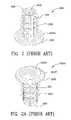
- barbs or prongs 202are illustrated protruding from shank 201 .
- Shank 201terminates in end portion 205 .
- Flange 203 Ftapers 203 T to edge 203 .
- Reference numeral 203 Udenotes the underside of the flange.
- Inner threads 204are illustrated in FIG. 2 .
- the advantages of this manufacturing methodinclude a part fully threaded all the way to the cap.
- the threadis fully formed from near the flange end of the T-Nut to the end of the barrel.
- a short fasteneris formed which functions as if it were a longer fastener.
- the manufacturing method for the short fastener of this inventionis highly automated and per part cycle times are low.
- the fastenercan be made from steel with a wide range of platings or even stainless steel for corrosion resistance.
- the fastenerwill be competitive from a manufactured cost standpoint.
- the fastenercan be made in a wide variety of thread sizes, barrel lengths and flange diameters. The flange provides excellent pull out resistance in molding applications.
- FIG. 1Ais another view of the screw machine brass insert.
- FIG. 2is a zinc die cast insert.
- FIG. 3Ais a another perspective view of the t-nut threaded completely through the part.
- FIG. 3Bis a top view of the t-nut with through threads.
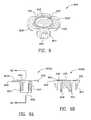
- FIG. 5is an exploded perspective view taken of the end cap and t-nut with through threads.
- FIG. 5Ais a perspective view of the end cap and the t-nut joined together.
- FIG. 5Bis an end view of the end cap secured to the t-nut.
- FIG. 5Dis a cross-sectional view taken along the lines 5 D- 5 D of FIG. 5C .
- FIG. 7Ais a front view of a 4-prong t-nut and end cap joined thereto.
Landscapes
- Engineering & Computer Science (AREA)
- General Engineering & Computer Science (AREA)
- Mechanical Engineering (AREA)
- Bolts, Nuts, And Washers (AREA)
Abstract
Description
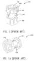
- 100—prior art screw machine brass insert.
- 100A—another view of the prior art screw machine brass insert
- 101—hexagonal head of the prior art screw machine brass insert
- 102—tapered recess leading to the threads of the prior art screw machine brass insert
- 103—inner threads of the prior art screw machine brass insert
- 104—larger hexagonal head of the prior art screw machine brass insert
- 105—shank of the prior art screw machine brass insert
- 200—prior art zinc die cast insert
- 200A—another view of the prior art zinc die cast insert
- 201—shank of the prior art zinc die cast insert
- 202—barb or prong of the prior art zinc die cast insert
- 203—end or edge of the head of the prior art zinc die cast insert
- 203F—flange or face of the head of the prior art zinc die cast insert
- 203T—tapered portion of the head of the prior art zinc die cast insert
- 203U—underside of the flange
- 204—inner threads of the prior art zinc die cast insert
- 205—end of the shank of the prior art zinc die cast insert
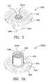
- 300—top perspective view of a t-nut thread all the way through the part
- 300A—another perspective view of the t-nut with thread all the way through the part
- 300B—top view of the t-nut with through threads.
- 300C—side view of the t-nut with through threads.
- 300D—cross-sectional view taken along the
lines 3D-3D ofFIG. 3C . - 301—flange of the head of the t-nut
- 302—threads of the t-nut
- 303—shank of the t-nut
- 304—radius interconnecting the shank and flange
- 305—flange
- 306—circumferential edge of the flange
- 308—end portion of the shank
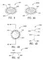
- 400—perspective view of the outer portion of the end cap of the invention
- 400A—perspective view of the inner portion of the end cap of the invention with a raised upper lip
- 400B—top view of the end cap
- 400C—side view of the end cap
- 400D—cross-sectional view taken along the
lines 4D-4D ofFIG. 4B - 401—lip of the end cap
- 402—annular recess in outer portion of the cap
- 403—outer/center portion of the cap
- 410—inner lip of the end cap
- 411—raised annular portion of the inside portion of the cap
- 412—inner/center portion of the cap
- 420—edge of the cap
- 500—exploded perspective view taken of the end cap and t-nut with through threads
- 500A—a perspective view of the end cap and the t-nut joined together
- 500B—end view of the end cap secured to the t-nut
- 500C—front view of the end cap
- 500D—cross-sectional view taken along the
lines 5D-5D ofFIG. 5C - 501—resistance weld of the end cap and the t-nut
- 600—perspective view of an upset hex t-nut and an end cap affixed thereto
- 600A—front view of an upset hex nut and end cap joined thereto
- 600B—cross-section of the upset hex nut and end cap illustrated in
FIG. 6A taken along thelines 6B-6B - 601—resistance weld of the end cap and the upset hex nut
- 601f—flange
- 602—threaded portion of the barrel
- 602A—slot between the upset edge portions of the upset hex nut
- 603—shank of the upset hex nut
- 608—end portion of the upset hex nut
- 620—upset edge portion of the upset hex nut
- 700—perspective view of a 4-prong t-nut and an end cap affixed thereto
- 700A—front view of a 4-prong t-nut and end cap joined thereto
- 700B—cross-sectional view of a 4-prong t-nut and an end cap illustrated in
FIG. 7A taken along thelines 7B-7B - 701—resistance weld of the end cap and the 4-prong t-nut
- 701F—flange portion of the 4-prong t-nut
- 702—threaded barrel
- 702A—cut portion of the 4-prong t-nut
- 703—shank of the 4-prong t-nut
- 704—deformed flap of the 4-prong t-nut
- 708—end of shank portion
- 800—perspective view of a propel nut and an end cap affixed thereto
- 800A—front view of a propel nut and end cap joined thereto
- 800B—cross-sectional view of a propel nut and an end cap illustrated in
FIG. 8A taken along thelines 8B-8B - 801—resistance weld of the end cap and the propel nut
- 801F—flange portion of the propel nut
- 802—threaded barrel
- 802A—barb on shank of the propel nut
- 803—shank of the propel nut
- 806—edge of the flange of the propel nut
- 900—perspective view of a hopper feed nut and an end cap affixed thereto
- 900A—front view of a hopper feed nut and end cap joined thereto
- 900B—cross-section of a hopper feed nut and an end cap illustrated in
FIG. 9A taken along thelines 9B-9B - 901—resistance weld of the end cap and the hopper feed nut
- 901F—flange portion of the hopper feed nut
- 906—edge of the flange of the hopper feed nut
- 907—prongs of the hopper feed nut
- 908—end of barrel
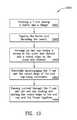
- 1000—schematic diagram for making the closed end fastener
- 1001—forming a t-nut having a barrel and a flange
- 1002—tapping the barrel and threading the barrel
- 1003—forming an end cap having a recess in the outer side thereof and a raised ridge on the inner side thereof
- 1004—forcefully interengaging the t-nut and the end cap with electrodes
- 1005—passing current through the t-nut and the end cap heating and melting the raised ridge of the end cap and the flange together
Claims (11)
Priority Applications (1)
| Application Number | Priority Date | Filing Date | Title |
|---|---|---|---|
| US12/329,601US8485910B2 (en) | 2008-08-18 | 2008-12-07 | Sealed end t-nut |
Applications Claiming Priority (2)
| Application Number | Priority Date | Filing Date | Title |
|---|---|---|---|
| US8985908P | 2008-08-18 | 2008-08-18 | |
| US12/329,601US8485910B2 (en) | 2008-08-18 | 2008-12-07 | Sealed end t-nut |
Publications (2)
| Publication Number | Publication Date |
|---|---|
| US20100041486A1 US20100041486A1 (en) | 2010-02-18 |
| US8485910B2true US8485910B2 (en) | 2013-07-16 |
Family
ID=41681649
Family Applications (1)
| Application Number | Title | Priority Date | Filing Date |
|---|---|---|---|
| US12/329,601Expired - Fee RelatedUS8485910B2 (en) | 2008-08-18 | 2008-12-07 | Sealed end t-nut |
Country Status (1)
| Country | Link |
|---|---|
| US (1) | US8485910B2 (en) |
Cited By (16)
| Publication number | Priority date | Publication date | Assignee | Title |
|---|---|---|---|---|
| US20120269599A1 (en)* | 2011-04-20 | 2012-10-25 | Shayan Malek | Threaded structures with solder management features |
| US20150192841A1 (en)* | 2014-01-07 | 2015-07-09 | Gopro, Inc. | Camera Mount for Sports Board |
| US9506577B2 (en)* | 2013-04-30 | 2016-11-29 | Tilden C. Harris | Safety valve device |
| US20170261024A1 (en)* | 2014-09-23 | 2017-09-14 | A-Fax Limited | Pin |
| USD894256S1 (en) | 2018-08-31 | 2020-08-25 | Gopro, Inc. | Camera mount |
| USD905786S1 (en) | 2018-08-31 | 2020-12-22 | Gopro, Inc. | Camera mount |
| US10928711B2 (en) | 2018-08-07 | 2021-02-23 | Gopro, Inc. | Camera and camera mount |
| US11306760B2 (en) | 2017-04-04 | 2022-04-19 | Daniel Paul Chairs, Llc | Non-rotating T-nut and screw catch for use in a chair panel and method for using the same |
| US11619254B2 (en)* | 2021-06-25 | 2023-04-04 | GM Global Technology Operations LLC | Protective covers for weld-on fasteners and welding processes using cover-protected weld-on fasteners |
| USD991318S1 (en) | 2020-08-14 | 2023-07-04 | Gopro, Inc. | Camera |
| USD997232S1 (en) | 2019-09-17 | 2023-08-29 | Gopro, Inc. | Camera |
| USD1036536S1 (en) | 2017-12-28 | 2024-07-23 | Gopro, Inc. | Camera |
| USD1043795S1 (en)* | 2022-04-21 | 2024-09-24 | Hongfeng Liu | Camera base |
| US12321084B2 (en) | 2022-08-12 | 2025-06-03 | Gopro, Inc. | Interconnect mechanism for image capture device |
| US12379650B2 (en) | 2023-02-15 | 2025-08-05 | Gopro, Inc. | Reinforced image capture devices including interconnect mechanisms with a threaded accessory interface |
| USD1096914S1 (en) | 2024-03-15 | 2025-10-07 | Gopro, Inc. | Camera mount |
Families Citing this family (3)
| Publication number | Priority date | Publication date | Assignee | Title |
|---|---|---|---|---|
| US8585000B2 (en)* | 2008-05-22 | 2013-11-19 | Mainstream Energy Corporation | Universal end clamp |
| CN105081188B (en)* | 2015-09-17 | 2017-09-12 | 宾科汽车紧固件(昆山)有限公司 | Electronic parking adjusting nut cold-heading device and its processing method |
| JP6955123B1 (en)* | 2020-11-02 | 2021-10-27 | 株式会社T・P・S・クリエーションズ | Surface mount nut manufacturing method, surface mount nut manufacturing equipment, bottomed tubular body manufacturing method, and surface mount nut |
Citations (156)
| Publication number | Priority date | Publication date | Assignee | Title |
|---|---|---|---|---|
| US180064A (en) | 1876-07-18 | Improvement in nuts | ||
| US244379A (en) | 1881-07-19 | Thumb-nut | ||
| US397988A (en) | 1889-02-19 | Thumb-nut wrench | ||
| US596948A (en) | 1898-01-04 | George a | ||
| US797545A (en) | 1905-04-17 | 1905-08-15 | Charles G Ette | Socket-washer. |
| US812294A (en) | 1905-05-29 | 1906-02-13 | Elijah T Harris | Wing-nut. |
| US1112525A (en) | 1913-05-05 | 1914-10-06 | Eastman Kodak Co | Tripod-socket for camera-beds. |
| US1773146A (en) | 1927-01-06 | 1930-08-19 | Central Screw Company | Wing nut |
| US1881836A (en) | 1926-02-15 | 1932-10-11 | Mitchell Robert | Clinch-on nut |
| US1893067A (en) | 1931-07-02 | 1933-01-03 | Lock Nut Company | Nut lock |
| US1919728A (en) | 1932-12-27 | 1933-07-25 | Central Screw Company | Wing nut |
| US2026757A (en) | 1934-07-24 | 1936-01-07 | Elastic Stop Nut Corp | Nut structure |
| US2049104A (en) | 1935-04-29 | 1936-07-28 | R A Simpson Mfg Company Inc | Wing nut |
| US2202405A (en)* | 1936-07-31 | 1940-05-28 | Midland Steel Prod Co | Method of resistance welding |
| US2208779A (en) | 1936-10-14 | 1940-07-23 | Tinnerman Products Inc | Fastening device |
| US2267379A (en) | 1938-09-28 | 1941-12-23 | Tinnerman Products Inc | Molding construction and the like |
| US2314756A (en) | 1941-06-14 | 1943-03-23 | United Carr Fastener Corp | Lock nut |
| US2321201A (en)* | 1942-06-15 | 1943-06-08 | Wall Wire Products Company | Welded nut and plate assembly and process of making the same |
| US2321497A (en) | 1941-05-08 | 1943-06-08 | Richard W Luce | Threaded locking device |
| US2343947A (en) | 1942-08-12 | 1944-03-14 | Auslander Henry | Wing nut |
| US2381936A (en) | 1942-07-23 | 1945-08-14 | United Carr Fastener Corp | Lock nut device |
| US2383141A (en) | 1943-02-23 | 1945-08-21 | Jr Alfred E Maage | Wing nut |
| US2477430A (en) | 1943-06-24 | 1949-07-26 | Swanstrom Klas Arent | Locking nut and method of manufacturing the same |
| US2685721A (en) | 1952-10-25 | 1954-08-10 | Illinois Tool Works | Resilient stud fastener |
| US2909206A (en)* | 1950-03-10 | 1959-10-20 | Kenneth L Johnson | Weld nut with inwardly sloping flash pockets |
| US2936668A (en) | 1956-09-17 | 1960-05-17 | Gen Motors Corp | Stud retaining spring clip |
| US2968206A (en) | 1957-07-23 | 1961-01-17 | Omoto Bunnosuke | Inner tube valve holder |
| US3004784A (en) | 1959-07-20 | 1961-10-17 | Tubular Structures Corp Of Ame | Coupling pin |
| US3037596A (en) | 1960-01-28 | 1962-06-05 | Ford Motor Co | Trim panel fastener |
| US3050097A (en) | 1959-10-22 | 1962-08-21 | United Carr Fastener Corp | Snap-in bolt retainer |
| US3146656A (en) | 1960-11-07 | 1964-09-01 | Richards Shear Company | Blade mounting bolts |
| US3234612A (en) | 1962-12-13 | 1966-02-15 | Raymond A | Panel fastener |
| US3235917A (en) | 1964-08-21 | 1966-02-22 | Leroy F Skubic | Mounting device |
| US3270610A (en)* | 1963-08-20 | 1966-09-06 | United Carr Inc | Sealed hollow fastener members |
| US3289724A (en) | 1964-02-20 | 1966-12-06 | Penn Eng & Mfg Corp | Self-locking nut having secured locking ring |
| US3319509A (en) | 1965-04-26 | 1967-05-16 | Romeo Costantino | Wing nut |
| US3353580A (en) | 1966-05-12 | 1967-11-21 | F & E Mfg Company | Nut and bolt construction |
| US3358727A (en) | 1965-02-26 | 1967-12-19 | United Carr Inc | Counterboring flanged nut |
| US3403218A (en) | 1967-07-28 | 1968-09-24 | Slater Electric Inc | Mounting means for wiring devices |
| US3461936A (en) | 1967-10-19 | 1969-08-19 | Robert D Weber | Self-retained tension nut |
| US3505636A (en) | 1967-05-08 | 1970-04-07 | Clell D Mcdowell | Clamping bolt assembly for an easily loosened clamp |
| US3646982A (en) | 1969-09-12 | 1972-03-07 | Rex Chainbelt Inc | Encapsulated floating and nonfloating fasteners |
| US3704507A (en) | 1970-03-23 | 1972-12-05 | Mac Lean Fogg Lock Nut Co | Method of fabricating and attaching pierce nuts to a panel |
| US3809139A (en) | 1972-05-26 | 1974-05-07 | Kean Mfg Corp | Clinch-slide nut, panel assembly and method of forming same |
| US3845860A (en) | 1971-04-01 | 1974-11-05 | Multifastener Corp | Fastener strip |
| US3878599A (en) | 1969-07-11 | 1975-04-22 | Multifastener Corp | Method of forming a nut and panel assembly |
| US3900967A (en) | 1974-07-26 | 1975-08-26 | Pease Co | Adjustable sill and threshold assembly |
| US3920059A (en) | 1970-02-20 | 1975-11-18 | Mac Lean Fogg Lock Nut Co | Combination of relatively thin sheet of metal and pierce nut |
| US3926236A (en) | 1972-10-30 | 1975-12-16 | Multifastener Corp | Self-fastening nut, panel assembly and apparatus |
| US3962828A (en) | 1974-08-01 | 1976-06-15 | Combustion Engineering, Inc. | Adjustable framing member |
| US3967412A (en) | 1975-09-17 | 1976-07-06 | Peachtree Doors, Inc. | Adjustable threshold |
| US3983388A (en) | 1975-10-06 | 1976-09-28 | Automation Systems, Inc. | Apparatus for hardware item inspection |
| US4018257A (en) | 1975-12-15 | 1977-04-19 | Cold Fasteners, Inc. | Self-flanging nut and joint construction |
| US4074464A (en) | 1976-10-04 | 1978-02-21 | Mccay Dariel | Adjustable threshold |
| US4172523A (en) | 1972-03-09 | 1979-10-30 | Walter Becker | Applicator for retaining rings |
| US4266460A (en)* | 1979-06-11 | 1981-05-12 | Klimowicz Jerome R | Multiple piece bolt-type fastener |
| US4279341A (en) | 1979-10-15 | 1981-07-21 | Illinois Tool Works Inc. | Fastener strip |
| US4306654A (en) | 1977-11-28 | 1981-12-22 | Maclean-Fogg Company | Flanged nut fastener strip |
| US4352258A (en) | 1980-08-04 | 1982-10-05 | Pease Company | Adjustable sill and threshold |
| US4376334A (en) | 1981-04-27 | 1983-03-15 | Illinois Tool Works Inc. | Method of making terminal clamp assembly |
| US4377360A (en) | 1980-05-05 | 1983-03-22 | Wire Products Company, Inc. | Channel nut and method of making same |
| US4379537A (en) | 1981-08-10 | 1983-04-12 | Whipple Patent Management Corporation | Cable hanger |
| US4387535A (en) | 1981-12-07 | 1983-06-14 | Manco Tape, Inc. | Adjustable threshold assembly |
| US4447987A (en) | 1981-03-19 | 1984-05-15 | Decor Doors Manufacturing Ltd. | Adjustable threshold and sill assembly |
| US4476653A (en) | 1983-01-10 | 1984-10-16 | John M. Chupik | Door sill and adjustable threshold |
| US4508478A (en) | 1983-07-11 | 1985-04-02 | Sigma Tool & Machine Limited | Tee nut fastener member |
| US4580322A (en) | 1982-06-24 | 1986-04-08 | Dzuz Fastener Co., Inc. | Quick release fastener |
| US4595325A (en) | 1984-09-28 | 1986-06-17 | Eaton Corporation | Self-locking prevailing torque fastener |
| US4768907A (en) | 1986-07-14 | 1988-09-06 | Gauron Richard F | Gang nut assembly |
| US4770275A (en) | 1985-05-29 | 1988-09-13 | Williams Patrick Y | Leveller for ladders and other apparatus |
| US4790701A (en) | 1987-05-08 | 1988-12-13 | Jacobson Mfg. Co., Inc. | Floating fastener retainer assembly with removable fasteners |
| US4860513A (en) | 1988-01-25 | 1989-08-29 | Whitman Robert E | Roofing fastener |
| US4903831A (en) | 1984-08-15 | 1990-02-27 | Francis Terry E | Automatic nailer system |
| US4913609A (en) | 1986-04-02 | 1990-04-03 | Emhart Industries, Inc. | Profiled bolt mounting unit |
| US4945680A (en) | 1989-02-14 | 1990-08-07 | Donat Flamand Inc. | Threshold system for a domestic door |
| US4961553A (en) | 1988-10-03 | 1990-10-09 | Todd George R | Support system for pipes and other loads |
| US4971499A (en) | 1984-12-24 | 1990-11-20 | Ladouceur Harold A | Nut and panel assembly |
| US4991365A (en) | 1989-06-09 | 1991-02-12 | Harter Corporation | Foot and leveling mechanism for panels in a relocatable wall |
| US5010690A (en) | 1990-04-14 | 1991-04-30 | Imperial Products, Inc. | Adjustable threshold assembly with water-tight seals |
| US5078537A (en) | 1990-11-01 | 1992-01-07 | Nic Autotec Co., Ltd. | Connecting device |
| US5096350A (en) | 1988-09-02 | 1992-03-17 | Buell Industries, Inc. | Cage nut |
| US5108238A (en) | 1991-03-20 | 1992-04-28 | Ewing Paul E | Torque limiting bolt for power wrench tightening |
| US5114014A (en) | 1991-02-19 | 1992-05-19 | David Ascalon | Token holder |
| US5136814A (en) | 1991-05-09 | 1992-08-11 | Headrick Management Corporation | Draining door sill assembly with adjustable threshold cap |
| US5138814A (en) | 1988-12-05 | 1992-08-18 | Lippert Holding Company | Wall partition units |
| US5152582A (en) | 1991-03-28 | 1992-10-06 | American Seating Company | Self-aligning fastener system having stud-engaging resilient legs |
| US5179804A (en) | 1991-10-31 | 1993-01-19 | Young Robert H | Self draining door sill assembly |
| US5195854A (en) | 1991-06-21 | 1993-03-23 | Nagayama Electronic Industry Co. Ltd. | Tee nut |
| US5199836A (en) | 1992-04-13 | 1993-04-06 | Gogarty Brian J | T-nut |
| US5205092A (en) | 1991-07-18 | 1993-04-27 | Psa Threshold Limited | Threshold mat |
| US5214843A (en) | 1990-04-23 | 1993-06-01 | Bromley Keith G | Apparatus for applying tee-nut fasteners to workpieces |
| US5230181A (en) | 1992-12-21 | 1993-07-27 | Imperial Products, Inc. | Adjustable threshold assembly with water-impervious seal |
| US5238344A (en) | 1991-05-16 | 1993-08-24 | Yutaka Nagayama | Tee nut |
| US5239728A (en) | 1992-06-23 | 1993-08-31 | Kawneer Company, Inc. | Interlocking adjustable center pivot |
| US5244326A (en) | 1992-05-19 | 1993-09-14 | Arne Henriksen | Closed end ridged neck threaded fastener |
| US5273351A (en) | 1991-06-28 | 1993-12-28 | Rubel Edward R | Directional fastener assembly |
| US5290131A (en)* | 1991-03-22 | 1994-03-01 | Arne Henriksen | Barbed shank fastener |
| US5297851A (en) | 1991-12-05 | 1994-03-29 | Westinghouse Electric Corp. | Chair fastening device |
| US5299686A (en) | 1990-04-23 | 1994-04-05 | Bromley Keith G | Rolled strip of tee-nut fasteners for tee-nut fastener setting apparatus |
| US5314427A (en) | 1992-10-13 | 1994-05-24 | Marlowe Goble E | Channel ligament clamp |
| US5327645A (en) | 1990-04-23 | 1994-07-12 | Bromley Keith G | Tee-nut fastener feed means for tee-nut fastener setting apparatus |
| US5348432A (en)* | 1993-05-14 | 1994-09-20 | Nagayama Electronic Industry Co., Ltd. | Tee nut |
| US5388940A (en) | 1993-11-18 | 1995-02-14 | Herren; Harold | Screen rail bolt retainer |
| US5391031A (en) | 1992-05-22 | 1995-02-21 | Unimation, Inc. | Method and insert for connecting components to plastic members |
| US5423645A (en) | 1993-08-04 | 1995-06-13 | Profil Verbindungstechnik Gmbh & Co. Kg | Fastener and panel assembly |
| US5426894A (en) | 1993-12-03 | 1995-06-27 | Headrick; J. Charles | Continuous sidelight sill with adaptable threshold caps |
| US5429466A (en) | 1993-07-02 | 1995-07-04 | Nagayama Electronic Industry Co. Ltd. | Tee nut |
| US5445483A (en) | 1993-08-23 | 1995-08-29 | Emhart Inc. | Female clinch fastener with cold-formed locking flange and associated installation method |
| US5489173A (en) | 1992-12-19 | 1996-02-06 | Hilti Aktiengesellschaft | Device for attachment to a fastening rail |
| US5501558A (en) | 1994-08-25 | 1996-03-26 | Sigma Tool & Machine | Anti-friction Tee-nut with deflected edges |
| US5503596A (en) | 1993-05-14 | 1996-04-02 | Nagayama Electronic Industry Co., Ltd. | Method of manufacturing tee nuts |
| US5517788A (en) | 1994-11-23 | 1996-05-21 | Imperial Products, Inc. | Adjustable threshold assembly with water-tight seal |
| US5524391A (en) | 1995-03-20 | 1996-06-11 | Imperial Products, Inc. | Adjustable threshold assembly with water-tight seal |
| US5564873A (en) | 1980-02-02 | 1996-10-15 | Multifastener Corporation | Self-attaching fastening element and method of attachment |
| US5588266A (en) | 1993-12-03 | 1996-12-31 | Headrick; J. Charles | Continuous sidelight sill with adaptable threshold caps and removable paint shield |
| US5611173A (en) | 1993-12-03 | 1997-03-18 | Headrick Manufacturing Co., Inc. | Continuous sidelight sill with adaptable threshold caps and removable paint shield |
| US5618144A (en) | 1995-09-11 | 1997-04-08 | Sigma Tool & Machine | Tee-nut with enlarged barrel end |
| US5624217A (en) | 1995-12-29 | 1997-04-29 | Hungerford, Jr.; Charles S. | Connector for facilitating a connection between a channel member and a support member |
| US5722131A (en) | 1995-07-25 | 1998-03-03 | Sigma Tool & Machine | Clip for furniture springs, and method of manufacture |
| US5762190A (en) | 1997-02-03 | 1998-06-09 | Sigma Tool & Machine | Tee-nut holder strip |
| US5863164A (en) | 1998-01-23 | 1999-01-26 | Sigma Tool & Machine | Tee-nut with radiussed barrel end |
| US5879119A (en) | 1997-06-27 | 1999-03-09 | 4B Elevator Components Limited | Bucket elevator construction bolt |
| US5893538A (en) | 1991-09-13 | 1999-04-13 | Onishi; Yoshio | Conduit clamp |
| US5904461A (en) | 1998-05-07 | 1999-05-18 | Mckarge, Jr.; Gerald G. | Locking T-nut |
| US5918738A (en) | 1998-11-12 | 1999-07-06 | Sigma Tool & Machine | Tee-nut strip with edge membranes |
| US5993320A (en) | 1997-07-11 | 1999-11-30 | Stafast Products Inc. | Tee nut and method of manufacture |
| US6071052A (en) | 1997-06-30 | 2000-06-06 | Lok-Mor, Inc. | Extended height lock nut |
| US6109849A (en) | 1998-07-16 | 2000-08-29 | Nagayama Electronic Industry Co., Ltd. | Tee nut |
| US6129431A (en) | 1996-12-30 | 2000-10-10 | Hansen, Jr.; Harold R. | Modular shelving system |
| US6129493A (en) | 1999-10-26 | 2000-10-10 | Sigma Tool & Machine | Tee-nut with globular shaped sleeve |
| US6131347A (en) | 1998-09-11 | 2000-10-17 | Krueger International, Inc. | Reconfigurable wall panel partition system |
| US6174117B1 (en) | 1998-04-07 | 2001-01-16 | Koyo Seiko Co., Ltd. | Fastening structure including a bolt having a serration that is press-fit into a bolt hole of a flange |
| US6183181B1 (en)* | 1999-10-27 | 2001-02-06 | Sigma Tool & Machine | Sealed end tee-nut |
| US6185870B1 (en) | 1999-08-06 | 2001-02-13 | Stafast Products, Inc. | Adjustable threshold assembly |
| US6203231B1 (en) | 1997-07-30 | 2001-03-20 | Arturo Salice S.P.A. | Fastening plate for a metal fitting means, preferably to fasten a hinge arm to a supporting wall of a piece of furniture |
| US6272814B1 (en) | 1999-11-22 | 2001-08-14 | Wakai & Co., Ltd. | Method of packaging nut assemblies |
| US6305888B1 (en) | 1999-10-06 | 2001-10-23 | Sigma Tool & Machine | T-nut with indented leading and trailing edge flanges |
| US6345477B1 (en) | 2000-03-24 | 2002-02-12 | Tt Technologies, Inc. | Door sill assembly having adjustable threshold |
| US6349907B1 (en) | 1997-12-29 | 2002-02-26 | Herman Miller, Inc. | Height adjustable glide device |
| US6407351B1 (en) | 1999-09-29 | 2002-06-18 | Premark Feg L.L.C. | Thread covering assembly for adjustable support feet and the like |
| US20030035700A1 (en) | 2001-08-20 | 2003-02-20 | Chi-Cheng Chiang | Anti-loosening nail exclusively for wood |
| US6550999B2 (en) | 2000-04-06 | 2003-04-22 | Lir France | Dispenser with disengageable screw mechanism |
| US6637994B2 (en) | 2002-03-26 | 2003-10-28 | Falcon Fasteners Reg'd | Square-headed rivet fastener |
| US6640968B2 (en) | 2001-09-13 | 2003-11-04 | Stafast Products, Inc. | Retainer |
| US6701570B2 (en) | 1997-09-09 | 2004-03-09 | Kimball International, Inc. | Standardized furniture unit and bracket therefor |
| US20040234356A1 (en) | 2001-08-15 | 2004-11-25 | Parker John M. | Self-attaching fastener |
| US6832696B2 (en) | 2001-12-20 | 2004-12-21 | Hilti Aktiengesellschaft | Strip magazine |
| US6854943B2 (en) | 2002-06-27 | 2005-02-15 | Nagayama Electronic Industry Co., Ltd. | T-nut |
| US7021221B2 (en) | 2003-04-07 | 2006-04-04 | Del Frari Paul J | Holding device with demountable panels and shelf |
| US7287732B2 (en) | 2005-05-31 | 2007-10-30 | Balistreri Thomas W | Leveling device |
| US20080069660A1 (en) | 2006-09-19 | 2008-03-20 | Stafast Products, Inc. | Hopper fed tee-nut having counterbore with nylon lock |
| US20080193254A1 (en) | 2007-02-09 | 2008-08-14 | Stephen Selle | Fastener |
| US7427180B2 (en) | 2001-08-15 | 2008-09-23 | Whitesell International Corporation | Self-attaching fastener systems |
| US7484700B2 (en) | 2007-02-09 | 2009-02-03 | Stafast Products, Inc. | Leveling device and method for making same |
| US7524129B2 (en) | 2006-06-01 | 2009-04-28 | Stafast Products, Inc. | Fastener and process for using same |
| US7540699B2 (en) | 2004-04-15 | 2009-06-02 | Stafast Products, Inc. | Adjustable threshold fastener with flanges |
- 2008
- 2008-12-07USUS12/329,601patent/US8485910B2/ennot_activeExpired - Fee Related
Patent Citations (161)
| Publication number | Priority date | Publication date | Assignee | Title |
|---|---|---|---|---|
| US180064A (en) | 1876-07-18 | Improvement in nuts | ||
| US244379A (en) | 1881-07-19 | Thumb-nut | ||
| US397988A (en) | 1889-02-19 | Thumb-nut wrench | ||
| US596948A (en) | 1898-01-04 | George a | ||
| US797545A (en) | 1905-04-17 | 1905-08-15 | Charles G Ette | Socket-washer. |
| US812294A (en) | 1905-05-29 | 1906-02-13 | Elijah T Harris | Wing-nut. |
| US1112525A (en) | 1913-05-05 | 1914-10-06 | Eastman Kodak Co | Tripod-socket for camera-beds. |
| US1881836A (en) | 1926-02-15 | 1932-10-11 | Mitchell Robert | Clinch-on nut |
| US1773146A (en) | 1927-01-06 | 1930-08-19 | Central Screw Company | Wing nut |
| US1893067A (en) | 1931-07-02 | 1933-01-03 | Lock Nut Company | Nut lock |
| US1919728A (en) | 1932-12-27 | 1933-07-25 | Central Screw Company | Wing nut |
| US2026757A (en) | 1934-07-24 | 1936-01-07 | Elastic Stop Nut Corp | Nut structure |
| US2049104A (en) | 1935-04-29 | 1936-07-28 | R A Simpson Mfg Company Inc | Wing nut |
| US2202405A (en)* | 1936-07-31 | 1940-05-28 | Midland Steel Prod Co | Method of resistance welding |
| US2208779A (en) | 1936-10-14 | 1940-07-23 | Tinnerman Products Inc | Fastening device |
| US2267379A (en) | 1938-09-28 | 1941-12-23 | Tinnerman Products Inc | Molding construction and the like |
| US2321497A (en) | 1941-05-08 | 1943-06-08 | Richard W Luce | Threaded locking device |
| US2314756A (en) | 1941-06-14 | 1943-03-23 | United Carr Fastener Corp | Lock nut |
| US2321201A (en)* | 1942-06-15 | 1943-06-08 | Wall Wire Products Company | Welded nut and plate assembly and process of making the same |
| US2381936A (en) | 1942-07-23 | 1945-08-14 | United Carr Fastener Corp | Lock nut device |
| US2343947A (en) | 1942-08-12 | 1944-03-14 | Auslander Henry | Wing nut |
| US2383141A (en) | 1943-02-23 | 1945-08-21 | Jr Alfred E Maage | Wing nut |
| US2477430A (en) | 1943-06-24 | 1949-07-26 | Swanstrom Klas Arent | Locking nut and method of manufacturing the same |
| US2909206A (en)* | 1950-03-10 | 1959-10-20 | Kenneth L Johnson | Weld nut with inwardly sloping flash pockets |
| US2685721A (en) | 1952-10-25 | 1954-08-10 | Illinois Tool Works | Resilient stud fastener |
| US2936668A (en) | 1956-09-17 | 1960-05-17 | Gen Motors Corp | Stud retaining spring clip |
| US2968206A (en) | 1957-07-23 | 1961-01-17 | Omoto Bunnosuke | Inner tube valve holder |
| US3004784A (en) | 1959-07-20 | 1961-10-17 | Tubular Structures Corp Of Ame | Coupling pin |
| US3050097A (en) | 1959-10-22 | 1962-08-21 | United Carr Fastener Corp | Snap-in bolt retainer |
| US3037596A (en) | 1960-01-28 | 1962-06-05 | Ford Motor Co | Trim panel fastener |
| US3146656A (en) | 1960-11-07 | 1964-09-01 | Richards Shear Company | Blade mounting bolts |
| US3234612A (en) | 1962-12-13 | 1966-02-15 | Raymond A | Panel fastener |
| US3270610A (en)* | 1963-08-20 | 1966-09-06 | United Carr Inc | Sealed hollow fastener members |
| US3289724A (en) | 1964-02-20 | 1966-12-06 | Penn Eng & Mfg Corp | Self-locking nut having secured locking ring |
| US3235917A (en) | 1964-08-21 | 1966-02-22 | Leroy F Skubic | Mounting device |
| US3358727A (en) | 1965-02-26 | 1967-12-19 | United Carr Inc | Counterboring flanged nut |
| US3319509A (en) | 1965-04-26 | 1967-05-16 | Romeo Costantino | Wing nut |
| US3353580A (en) | 1966-05-12 | 1967-11-21 | F & E Mfg Company | Nut and bolt construction |
| US3505636A (en) | 1967-05-08 | 1970-04-07 | Clell D Mcdowell | Clamping bolt assembly for an easily loosened clamp |
| US3403218A (en) | 1967-07-28 | 1968-09-24 | Slater Electric Inc | Mounting means for wiring devices |
| US3461936A (en) | 1967-10-19 | 1969-08-19 | Robert D Weber | Self-retained tension nut |
| US3878599A (en) | 1969-07-11 | 1975-04-22 | Multifastener Corp | Method of forming a nut and panel assembly |
| US3646982A (en) | 1969-09-12 | 1972-03-07 | Rex Chainbelt Inc | Encapsulated floating and nonfloating fasteners |
| US3920059A (en) | 1970-02-20 | 1975-11-18 | Mac Lean Fogg Lock Nut Co | Combination of relatively thin sheet of metal and pierce nut |
| US3704507A (en) | 1970-03-23 | 1972-12-05 | Mac Lean Fogg Lock Nut Co | Method of fabricating and attaching pierce nuts to a panel |
| US3845860A (en) | 1971-04-01 | 1974-11-05 | Multifastener Corp | Fastener strip |
| US4172523A (en) | 1972-03-09 | 1979-10-30 | Walter Becker | Applicator for retaining rings |
| US3809139A (en) | 1972-05-26 | 1974-05-07 | Kean Mfg Corp | Clinch-slide nut, panel assembly and method of forming same |
| US3926236A (en) | 1972-10-30 | 1975-12-16 | Multifastener Corp | Self-fastening nut, panel assembly and apparatus |
| US3900967A (en) | 1974-07-26 | 1975-08-26 | Pease Co | Adjustable sill and threshold assembly |
| US3962828A (en) | 1974-08-01 | 1976-06-15 | Combustion Engineering, Inc. | Adjustable framing member |
| US3967412A (en) | 1975-09-17 | 1976-07-06 | Peachtree Doors, Inc. | Adjustable threshold |
| US3983388A (en) | 1975-10-06 | 1976-09-28 | Automation Systems, Inc. | Apparatus for hardware item inspection |
| US4018257A (en) | 1975-12-15 | 1977-04-19 | Cold Fasteners, Inc. | Self-flanging nut and joint construction |
| US4074464A (en) | 1976-10-04 | 1978-02-21 | Mccay Dariel | Adjustable threshold |
| US4306654A (en) | 1977-11-28 | 1981-12-22 | Maclean-Fogg Company | Flanged nut fastener strip |
| US4266460A (en)* | 1979-06-11 | 1981-05-12 | Klimowicz Jerome R | Multiple piece bolt-type fastener |
| US4279341A (en) | 1979-10-15 | 1981-07-21 | Illinois Tool Works Inc. | Fastener strip |
| US5564873A (en) | 1980-02-02 | 1996-10-15 | Multifastener Corporation | Self-attaching fastening element and method of attachment |
| US4377360A (en) | 1980-05-05 | 1983-03-22 | Wire Products Company, Inc. | Channel nut and method of making same |
| US4352258A (en) | 1980-08-04 | 1982-10-05 | Pease Company | Adjustable sill and threshold |
| US4447987A (en) | 1981-03-19 | 1984-05-15 | Decor Doors Manufacturing Ltd. | Adjustable threshold and sill assembly |
| US4376334A (en) | 1981-04-27 | 1983-03-15 | Illinois Tool Works Inc. | Method of making terminal clamp assembly |
| US4379537A (en) | 1981-08-10 | 1983-04-12 | Whipple Patent Management Corporation | Cable hanger |
| US4387535A (en) | 1981-12-07 | 1983-06-14 | Manco Tape, Inc. | Adjustable threshold assembly |
| US4580322A (en) | 1982-06-24 | 1986-04-08 | Dzuz Fastener Co., Inc. | Quick release fastener |
| US4476653A (en) | 1983-01-10 | 1984-10-16 | John M. Chupik | Door sill and adjustable threshold |
| US4508478A (en) | 1983-07-11 | 1985-04-02 | Sigma Tool & Machine Limited | Tee nut fastener member |
| US4903831A (en) | 1984-08-15 | 1990-02-27 | Francis Terry E | Automatic nailer system |
| US4595325A (en) | 1984-09-28 | 1986-06-17 | Eaton Corporation | Self-locking prevailing torque fastener |
| US4971499A (en) | 1984-12-24 | 1990-11-20 | Ladouceur Harold A | Nut and panel assembly |
| US4770275A (en) | 1985-05-29 | 1988-09-13 | Williams Patrick Y | Leveller for ladders and other apparatus |
| US4913609A (en) | 1986-04-02 | 1990-04-03 | Emhart Industries, Inc. | Profiled bolt mounting unit |
| US4768907A (en) | 1986-07-14 | 1988-09-06 | Gauron Richard F | Gang nut assembly |
| US4790701A (en) | 1987-05-08 | 1988-12-13 | Jacobson Mfg. Co., Inc. | Floating fastener retainer assembly with removable fasteners |
| US4860513A (en) | 1988-01-25 | 1989-08-29 | Whitman Robert E | Roofing fastener |
| US5096350A (en) | 1988-09-02 | 1992-03-17 | Buell Industries, Inc. | Cage nut |
| US4961553A (en) | 1988-10-03 | 1990-10-09 | Todd George R | Support system for pipes and other loads |
| US5138814A (en) | 1988-12-05 | 1992-08-18 | Lippert Holding Company | Wall partition units |
| US4945680A (en) | 1989-02-14 | 1990-08-07 | Donat Flamand Inc. | Threshold system for a domestic door |
| US4991365A (en) | 1989-06-09 | 1991-02-12 | Harter Corporation | Foot and leveling mechanism for panels in a relocatable wall |
| US5010690A (en) | 1990-04-14 | 1991-04-30 | Imperial Products, Inc. | Adjustable threshold assembly with water-tight seals |
| US5214843A (en) | 1990-04-23 | 1993-06-01 | Bromley Keith G | Apparatus for applying tee-nut fasteners to workpieces |
| US5327645A (en) | 1990-04-23 | 1994-07-12 | Bromley Keith G | Tee-nut fastener feed means for tee-nut fastener setting apparatus |
| US5299686A (en) | 1990-04-23 | 1994-04-05 | Bromley Keith G | Rolled strip of tee-nut fasteners for tee-nut fastener setting apparatus |
| US5078537A (en) | 1990-11-01 | 1992-01-07 | Nic Autotec Co., Ltd. | Connecting device |
| US5114014A (en) | 1991-02-19 | 1992-05-19 | David Ascalon | Token holder |
| US5108238A (en) | 1991-03-20 | 1992-04-28 | Ewing Paul E | Torque limiting bolt for power wrench tightening |
| US5290131A (en)* | 1991-03-22 | 1994-03-01 | Arne Henriksen | Barbed shank fastener |
| US5152582A (en) | 1991-03-28 | 1992-10-06 | American Seating Company | Self-aligning fastener system having stud-engaging resilient legs |
| US5136814A (en) | 1991-05-09 | 1992-08-11 | Headrick Management Corporation | Draining door sill assembly with adjustable threshold cap |
| US5238344A (en) | 1991-05-16 | 1993-08-24 | Yutaka Nagayama | Tee nut |
| US5195854A (en) | 1991-06-21 | 1993-03-23 | Nagayama Electronic Industry Co. Ltd. | Tee nut |
| US5273351A (en) | 1991-06-28 | 1993-12-28 | Rubel Edward R | Directional fastener assembly |
| US5205092A (en) | 1991-07-18 | 1993-04-27 | Psa Threshold Limited | Threshold mat |
| US5893538A (en) | 1991-09-13 | 1999-04-13 | Onishi; Yoshio | Conduit clamp |
| US5179804A (en) | 1991-10-31 | 1993-01-19 | Young Robert H | Self draining door sill assembly |
| US5297851A (en) | 1991-12-05 | 1994-03-29 | Westinghouse Electric Corp. | Chair fastening device |
| US5199836A (en) | 1992-04-13 | 1993-04-06 | Gogarty Brian J | T-nut |
| US5244326A (en) | 1992-05-19 | 1993-09-14 | Arne Henriksen | Closed end ridged neck threaded fastener |
| US5391031A (en) | 1992-05-22 | 1995-02-21 | Unimation, Inc. | Method and insert for connecting components to plastic members |
| US5239728A (en) | 1992-06-23 | 1993-08-31 | Kawneer Company, Inc. | Interlocking adjustable center pivot |
| US5314427A (en) | 1992-10-13 | 1994-05-24 | Marlowe Goble E | Channel ligament clamp |
| US5489173A (en) | 1992-12-19 | 1996-02-06 | Hilti Aktiengesellschaft | Device for attachment to a fastening rail |
| US5230181A (en) | 1992-12-21 | 1993-07-27 | Imperial Products, Inc. | Adjustable threshold assembly with water-impervious seal |
| US5348432A (en)* | 1993-05-14 | 1994-09-20 | Nagayama Electronic Industry Co., Ltd. | Tee nut |
| US5348432C1 (en)* | 1993-05-14 | 2001-01-09 | Nagayama Denshi Kogyo Kk | Tee nut |
| US5503596A (en) | 1993-05-14 | 1996-04-02 | Nagayama Electronic Industry Co., Ltd. | Method of manufacturing tee nuts |
| US5429466A (en) | 1993-07-02 | 1995-07-04 | Nagayama Electronic Industry Co. Ltd. | Tee nut |
| US5423645A (en) | 1993-08-04 | 1995-06-13 | Profil Verbindungstechnik Gmbh & Co. Kg | Fastener and panel assembly |
| US5445483A (en) | 1993-08-23 | 1995-08-29 | Emhart Inc. | Female clinch fastener with cold-formed locking flange and associated installation method |
| US5388940A (en) | 1993-11-18 | 1995-02-14 | Herren; Harold | Screen rail bolt retainer |
| US5588266A (en) | 1993-12-03 | 1996-12-31 | Headrick; J. Charles | Continuous sidelight sill with adaptable threshold caps and removable paint shield |
| US5611173A (en) | 1993-12-03 | 1997-03-18 | Headrick Manufacturing Co., Inc. | Continuous sidelight sill with adaptable threshold caps and removable paint shield |
| US5426894A (en) | 1993-12-03 | 1995-06-27 | Headrick; J. Charles | Continuous sidelight sill with adaptable threshold caps |
| US5501558A (en) | 1994-08-25 | 1996-03-26 | Sigma Tool & Machine | Anti-friction Tee-nut with deflected edges |
| US5517788A (en) | 1994-11-23 | 1996-05-21 | Imperial Products, Inc. | Adjustable threshold assembly with water-tight seal |
| US5524391A (en) | 1995-03-20 | 1996-06-11 | Imperial Products, Inc. | Adjustable threshold assembly with water-tight seal |
| US5638641A (en) | 1995-03-20 | 1997-06-17 | Imperial Products, Inc. | Adjustable threshold assembly with water-tight seal |
| US5722131A (en) | 1995-07-25 | 1998-03-03 | Sigma Tool & Machine | Clip for furniture springs, and method of manufacture |
| US5618144A (en) | 1995-09-11 | 1997-04-08 | Sigma Tool & Machine | Tee-nut with enlarged barrel end |
| US5624217A (en) | 1995-12-29 | 1997-04-29 | Hungerford, Jr.; Charles S. | Connector for facilitating a connection between a channel member and a support member |
| US6129431A (en) | 1996-12-30 | 2000-10-10 | Hansen, Jr.; Harold R. | Modular shelving system |
| US5762190A (en) | 1997-02-03 | 1998-06-09 | Sigma Tool & Machine | Tee-nut holder strip |
| US5879119A (en) | 1997-06-27 | 1999-03-09 | 4B Elevator Components Limited | Bucket elevator construction bolt |
| US6071052A (en) | 1997-06-30 | 2000-06-06 | Lok-Mor, Inc. | Extended height lock nut |
| US5993320A (en) | 1997-07-11 | 1999-11-30 | Stafast Products Inc. | Tee nut and method of manufacture |
| US6095738A (en) | 1997-07-11 | 2000-08-01 | Stafast Products, Inc. | Tee nut and method of manufacture |
| US6203231B1 (en) | 1997-07-30 | 2001-03-20 | Arturo Salice S.P.A. | Fastening plate for a metal fitting means, preferably to fasten a hinge arm to a supporting wall of a piece of furniture |
| US6701570B2 (en) | 1997-09-09 | 2004-03-09 | Kimball International, Inc. | Standardized furniture unit and bracket therefor |
| US6349907B1 (en) | 1997-12-29 | 2002-02-26 | Herman Miller, Inc. | Height adjustable glide device |
| US5863164A (en) | 1998-01-23 | 1999-01-26 | Sigma Tool & Machine | Tee-nut with radiussed barrel end |
| US6174117B1 (en) | 1998-04-07 | 2001-01-16 | Koyo Seiko Co., Ltd. | Fastening structure including a bolt having a serration that is press-fit into a bolt hole of a flange |
| US5904461A (en) | 1998-05-07 | 1999-05-18 | Mckarge, Jr.; Gerald G. | Locking T-nut |
| US6109849A (en) | 1998-07-16 | 2000-08-29 | Nagayama Electronic Industry Co., Ltd. | Tee nut |
| US6131347A (en) | 1998-09-11 | 2000-10-17 | Krueger International, Inc. | Reconfigurable wall panel partition system |
| US5918738A (en) | 1998-11-12 | 1999-07-06 | Sigma Tool & Machine | Tee-nut strip with edge membranes |
| US6209722B1 (en) | 1998-11-12 | 2001-04-03 | Sigma Tool & Machine, A Partnership Of Sigma Tool & Machine Ltd. | Tee-nut strip with edge membranes |
| US6185870B1 (en) | 1999-08-06 | 2001-02-13 | Stafast Products, Inc. | Adjustable threshold assembly |
| US6407351B1 (en) | 1999-09-29 | 2002-06-18 | Premark Feg L.L.C. | Thread covering assembly for adjustable support feet and the like |
| US6305888B1 (en) | 1999-10-06 | 2001-10-23 | Sigma Tool & Machine | T-nut with indented leading and trailing edge flanges |
| US6129493A (en) | 1999-10-26 | 2000-10-10 | Sigma Tool & Machine | Tee-nut with globular shaped sleeve |
| US6183181B1 (en)* | 1999-10-27 | 2001-02-06 | Sigma Tool & Machine | Sealed end tee-nut |
| US6272814B1 (en) | 1999-11-22 | 2001-08-14 | Wakai & Co., Ltd. | Method of packaging nut assemblies |
| US6345477B1 (en) | 2000-03-24 | 2002-02-12 | Tt Technologies, Inc. | Door sill assembly having adjustable threshold |
| US6550999B2 (en) | 2000-04-06 | 2003-04-22 | Lir France | Dispenser with disengageable screw mechanism |
| US7427180B2 (en) | 2001-08-15 | 2008-09-23 | Whitesell International Corporation | Self-attaching fastener systems |
| US20040234356A1 (en) | 2001-08-15 | 2004-11-25 | Parker John M. | Self-attaching fastener |
| US20030035700A1 (en) | 2001-08-20 | 2003-02-20 | Chi-Cheng Chiang | Anti-loosening nail exclusively for wood |
| US6640968B2 (en) | 2001-09-13 | 2003-11-04 | Stafast Products, Inc. | Retainer |
| US6832696B2 (en) | 2001-12-20 | 2004-12-21 | Hilti Aktiengesellschaft | Strip magazine |
| US6637994B2 (en) | 2002-03-26 | 2003-10-28 | Falcon Fasteners Reg'd | Square-headed rivet fastener |
| US6854943B2 (en) | 2002-06-27 | 2005-02-15 | Nagayama Electronic Industry Co., Ltd. | T-nut |
| US7021221B2 (en) | 2003-04-07 | 2006-04-04 | Del Frari Paul J | Holding device with demountable panels and shelf |
| US7540699B2 (en) | 2004-04-15 | 2009-06-02 | Stafast Products, Inc. | Adjustable threshold fastener with flanges |
| US7287732B2 (en) | 2005-05-31 | 2007-10-30 | Balistreri Thomas W | Leveling device |
| US7524129B2 (en) | 2006-06-01 | 2009-04-28 | Stafast Products, Inc. | Fastener and process for using same |
| US20080069660A1 (en) | 2006-09-19 | 2008-03-20 | Stafast Products, Inc. | Hopper fed tee-nut having counterbore with nylon lock |
| US7674081B2 (en) | 2006-09-19 | 2010-03-09 | Stafast Products, Inc. | Hopper fed tee-nut having counterbore with nylon lock |
| US20080193254A1 (en) | 2007-02-09 | 2008-08-14 | Stephen Selle | Fastener |
| US7484700B2 (en) | 2007-02-09 | 2009-02-03 | Stafast Products, Inc. | Leveling device and method for making same |
Non-Patent Citations (1)
| Title |
|---|
| Groover, Mikell, Fundamentals of Modern Manufacturing, 2002, John Wiley & Sons, 2nd Edition, p. 703.* |
Cited By (28)
| Publication number | Priority date | Publication date | Assignee | Title |
|---|---|---|---|---|
| US20120269599A1 (en)* | 2011-04-20 | 2012-10-25 | Shayan Malek | Threaded structures with solder management features |
| US9506577B2 (en)* | 2013-04-30 | 2016-11-29 | Tilden C. Harris | Safety valve device |
| US20170051839A1 (en)* | 2013-04-30 | 2017-02-23 | Tilden C. Harris | Safety valve device |
| US20150192841A1 (en)* | 2014-01-07 | 2015-07-09 | Gopro, Inc. | Camera Mount for Sports Board |
| US9122133B2 (en)* | 2014-01-07 | 2015-09-01 | Gopro, Inc. | Camera mount for sports board |
| US9513535B2 (en)* | 2014-01-07 | 2016-12-06 | Gopro, Inc. | Camera mount for sports board |
| US20170261024A1 (en)* | 2014-09-23 | 2017-09-14 | A-Fax Limited | Pin |
| US10711819B2 (en)* | 2014-09-23 | 2020-07-14 | Three Smith Group Limited | Pin |
| US11306760B2 (en) | 2017-04-04 | 2022-04-19 | Daniel Paul Chairs, Llc | Non-rotating T-nut and screw catch for use in a chair panel and method for using the same |
| USD1079788S1 (en) | 2017-12-28 | 2025-06-17 | Gopro, Inc. | Camera |
| USD1036536S1 (en) | 2017-12-28 | 2024-07-23 | Gopro, Inc. | Camera |
| US12399419B2 (en) | 2018-08-07 | 2025-08-26 | Gopro, Inc. | Camera and camera mount |
| US10928711B2 (en) | 2018-08-07 | 2021-02-23 | Gopro, Inc. | Camera and camera mount |
| US11662651B2 (en) | 2018-08-07 | 2023-05-30 | Gopro, Inc. | Camera and camera mount |
| USD989165S1 (en) | 2018-08-31 | 2023-06-13 | Gopro, Inc. | Camera mount |
| USD894256S1 (en) | 2018-08-31 | 2020-08-25 | Gopro, Inc. | Camera mount |
| USD1023115S1 (en) | 2018-08-31 | 2024-04-16 | Gopro, Inc. | Camera mount |
| USD905786S1 (en) | 2018-08-31 | 2020-12-22 | Gopro, Inc. | Camera mount |
| USD997232S1 (en) | 2019-09-17 | 2023-08-29 | Gopro, Inc. | Camera |
| USD1024165S1 (en) | 2019-09-17 | 2024-04-23 | Gopro, Inc. | Camera |
| USD1090676S1 (en) | 2019-09-17 | 2025-08-26 | Gopro, Inc. | Camera |
| USD1004676S1 (en) | 2020-08-14 | 2023-11-14 | Gopro, Inc. | Camera |
| USD991318S1 (en) | 2020-08-14 | 2023-07-04 | Gopro, Inc. | Camera |
| US11619254B2 (en)* | 2021-06-25 | 2023-04-04 | GM Global Technology Operations LLC | Protective covers for weld-on fasteners and welding processes using cover-protected weld-on fasteners |
| USD1043795S1 (en)* | 2022-04-21 | 2024-09-24 | Hongfeng Liu | Camera base |
| US12321084B2 (en) | 2022-08-12 | 2025-06-03 | Gopro, Inc. | Interconnect mechanism for image capture device |
| US12379650B2 (en) | 2023-02-15 | 2025-08-05 | Gopro, Inc. | Reinforced image capture devices including interconnect mechanisms with a threaded accessory interface |
| USD1096914S1 (en) | 2024-03-15 | 2025-10-07 | Gopro, Inc. | Camera mount |
Also Published As
| Publication number | Publication date |
|---|---|
| US20100041486A1 (en) | 2010-02-18 |
Similar Documents
| Publication | Publication Date | Title |
|---|---|---|
| US8485910B2 (en) | Sealed end t-nut | |
| CN106660162B (en) | It is adapted to couple to the engagement auxiliary element of the method for few two components | |
| CA2683277C (en) | Component assembly consisting of a fastener element and a sheet metal part and also a method for manufacturing such a component assembly | |
| US10903587B2 (en) | Resistance welding fastener, apparatus and methods | |
| US3635272A (en) | Threaded fastening device and method of making the same | |
| US8939689B2 (en) | Functional element in the form of a press-in element | |
| US7401394B1 (en) | Method of attaching a fastener element to a metal panel | |
| US20170317432A1 (en) | Cable lug comprising a nut or functional part, method for the production of such a cable lug, and nut | |
| US8007216B2 (en) | Plastic threaded insert | |
| US9695853B2 (en) | High energy absorption joint | |
| EP3936272A1 (en) | Resistance welding fastener | |
| US20110097173A1 (en) | Functional element, component assembly comprising the functional element in combination with a sheet metal part, method for the manufacture of a component assembly and also method for the manufacture of the functional element | |
| US3353849A (en) | Plastic container closure assembly | |
| EP0707688A1 (en) | Insert for connecting components to plastic members | |
| EP0537824A2 (en) | Ultrasonic insert stud and method of assembly | |
| US8591158B2 (en) | Spacer element for the attachment of a sheet metal part, component assembly and method for its manufacture | |
| JPS6249490B2 (en) | ||
| US6765171B1 (en) | Projection welding of flanged weld nut | |
| FI79207C (en) | Electrical contact device for sandwich-like, plastic and at least one plastic membrane enclosed with a metal membrane | |
| KR100785550B1 (en) | Nut for press-fit joining, press-fit joining structure and press-fit joining method using the same | |
| JPH1158518A (en) | Plastic welding method and device therefor | |
| CN211525300U (en) | Arrow-shaped embossing tooth pressure riveting nut | |
| JPS597551B2 (en) | Nut welding method | |
| CN210318111U (en) | Anti-rotation riveting nut for plastic workpiece | |
| JP2019093633A (en) | Manufacturing method of metal resin conjugate |
Legal Events
| Date | Code | Title | Description |
|---|---|---|---|
| AS | Assignment | Owner name:STAFAST PRODUCTS, INC.,OHIO Free format text:ASSIGNMENT OF ASSIGNORS INTEREST;ASSIGNOR:SELLE, STEPHEN;REEL/FRAME:021934/0548 Effective date:20081121 Owner name:STAFAST PRODUCTS, INC., OHIO Free format text:ASSIGNMENT OF ASSIGNORS INTEREST;ASSIGNOR:SELLE, STEPHEN;REEL/FRAME:021934/0548 Effective date:20081121 | |
| STCF | Information on status: patent grant | Free format text:PATENTED CASE | |
| CC | Certificate of correction | ||
| FPAY | Fee payment | Year of fee payment:4 | |
| MAFP | Maintenance fee payment | Free format text:PAYMENT OF MAINTENANCE FEE, 8TH YR, SMALL ENTITY (ORIGINAL EVENT CODE: M2552); ENTITY STATUS OF PATENT OWNER: SMALL ENTITY Year of fee payment:8 | |
| FEPP | Fee payment procedure | Free format text:MAINTENANCE FEE REMINDER MAILED (ORIGINAL EVENT CODE: REM.); ENTITY STATUS OF PATENT OWNER: SMALL ENTITY | |
| LAPS | Lapse for failure to pay maintenance fees | Free format text:PATENT EXPIRED FOR FAILURE TO PAY MAINTENANCE FEES (ORIGINAL EVENT CODE: EXP.); ENTITY STATUS OF PATENT OWNER: SMALL ENTITY | |
| STCH | Information on status: patent discontinuation | Free format text:PATENT EXPIRED DUE TO NONPAYMENT OF MAINTENANCE FEES UNDER 37 CFR 1.362 | |
| FP | Lapsed due to failure to pay maintenance fee | Effective date:20250716 |