US8485820B1 - Devices and methods for enhancing bone growth - Google Patents
Devices and methods for enhancing bone growthDownload PDFInfo
- Publication number
- US8485820B1 US8485820B1US13/335,371US201113335371AUS8485820B1US 8485820 B1US8485820 B1US 8485820B1US 201113335371 AUS201113335371 AUS 201113335371AUS 8485820 B1US8485820 B1US 8485820B1
- Authority
- US
- United States
- Prior art keywords
- bone
- patient
- rig
- implant
- receiving
- Prior art date
- Legal status (The legal status is an assumption and is not a legal conclusion. Google has not performed a legal analysis and makes no representation as to the accuracy of the status listed.)
- Expired - Fee Related
Links
Images


Classifications
- A—HUMAN NECESSITIES
- A61—MEDICAL OR VETERINARY SCIENCE; HYGIENE
- A61C—DENTISTRY; APPARATUS OR METHODS FOR ORAL OR DENTAL HYGIENE
- A61C8/00—Means to be fixed to the jaw-bone for consolidating natural teeth or for fixing dental prostheses thereon; Dental implants; Implanting tools
- A61C8/0018—Means to be fixed to the jaw-bone for consolidating natural teeth or for fixing dental prostheses thereon; Dental implants; Implanting tools characterised by the shape
- A61C8/0027—Frames
- A—HUMAN NECESSITIES
- A61—MEDICAL OR VETERINARY SCIENCE; HYGIENE
- A61B—DIAGNOSIS; SURGERY; IDENTIFICATION
- A61B6/00—Apparatus or devices for radiation diagnosis; Apparatus or devices for radiation diagnosis combined with radiation therapy equipment
- A61B6/02—Arrangements for diagnosis sequentially in different planes; Stereoscopic radiation diagnosis
- A61B6/03—Computed tomography [CT]
- A61B6/032—Transmission computed tomography [CT]
- A—HUMAN NECESSITIES
- A61—MEDICAL OR VETERINARY SCIENCE; HYGIENE
- A61B—DIAGNOSIS; SURGERY; IDENTIFICATION
- A61B6/00—Apparatus or devices for radiation diagnosis; Apparatus or devices for radiation diagnosis combined with radiation therapy equipment
- A61B6/50—Apparatus or devices for radiation diagnosis; Apparatus or devices for radiation diagnosis combined with radiation therapy equipment specially adapted for specific body parts; specially adapted for specific clinical applications
- A61B6/51—Apparatus or devices for radiation diagnosis; Apparatus or devices for radiation diagnosis combined with radiation therapy equipment specially adapted for specific body parts; specially adapted for specific clinical applications for dentistry
- A—HUMAN NECESSITIES
- A61—MEDICAL OR VETERINARY SCIENCE; HYGIENE
- A61C—DENTISTRY; APPARATUS OR METHODS FOR ORAL OR DENTAL HYGIENE
- A61C13/00—Dental prostheses; Making same
- A61C13/0003—Making bridge-work, inlays, implants or the like
- A61C13/0006—Production methods
- A61C13/0019—Production methods using three dimensional printing
- A—HUMAN NECESSITIES
- A61—MEDICAL OR VETERINARY SCIENCE; HYGIENE
- A61C—DENTISTRY; APPARATUS OR METHODS FOR ORAL OR DENTAL HYGIENE
- A61C8/00—Means to be fixed to the jaw-bone for consolidating natural teeth or for fixing dental prostheses thereon; Dental implants; Implanting tools
- A61C8/0003—Not used, see subgroups
- A61C8/0004—Consolidating natural teeth
- A61C8/0006—Periodontal tissue or bone regeneration
- A—HUMAN NECESSITIES
- A61—MEDICAL OR VETERINARY SCIENCE; HYGIENE
- A61C—DENTISTRY; APPARATUS OR METHODS FOR ORAL OR DENTAL HYGIENE
- A61C8/00—Means to be fixed to the jaw-bone for consolidating natural teeth or for fixing dental prostheses thereon; Dental implants; Implanting tools
- A61C8/0018—Means to be fixed to the jaw-bone for consolidating natural teeth or for fixing dental prostheses thereon; Dental implants; Implanting tools characterised by the shape
- A61C8/0031—Juxtaosseous implants, i.e. implants lying over the outer surface of the jaw bone
- A—HUMAN NECESSITIES
- A61—MEDICAL OR VETERINARY SCIENCE; HYGIENE
- A61C—DENTISTRY; APPARATUS OR METHODS FOR ORAL OR DENTAL HYGIENE
- A61C8/00—Means to be fixed to the jaw-bone for consolidating natural teeth or for fixing dental prostheses thereon; Dental implants; Implanting tools
- A61C8/0018—Means to be fixed to the jaw-bone for consolidating natural teeth or for fixing dental prostheses thereon; Dental implants; Implanting tools characterised by the shape
- A61C8/0036—Tooth replica
- A—HUMAN NECESSITIES
- A61—MEDICAL OR VETERINARY SCIENCE; HYGIENE
- A61F—FILTERS IMPLANTABLE INTO BLOOD VESSELS; PROSTHESES; DEVICES PROVIDING PATENCY TO, OR PREVENTING COLLAPSING OF, TUBULAR STRUCTURES OF THE BODY, e.g. STENTS; ORTHOPAEDIC, NURSING OR CONTRACEPTIVE DEVICES; FOMENTATION; TREATMENT OR PROTECTION OF EYES OR EARS; BANDAGES, DRESSINGS OR ABSORBENT PADS; FIRST-AID KITS
- A61F2/00—Filters implantable into blood vessels; Prostheses, i.e. artificial substitutes or replacements for parts of the body; Appliances for connecting them with the body; Devices providing patency to, or preventing collapsing of, tubular structures of the body, e.g. stents
- A61F2/02—Prostheses implantable into the body
- A61F2/28—Bones
- A61F2/2803—Bones for mandibular reconstruction
- A—HUMAN NECESSITIES
- A61—MEDICAL OR VETERINARY SCIENCE; HYGIENE
- A61F—FILTERS IMPLANTABLE INTO BLOOD VESSELS; PROSTHESES; DEVICES PROVIDING PATENCY TO, OR PREVENTING COLLAPSING OF, TUBULAR STRUCTURES OF THE BODY, e.g. STENTS; ORTHOPAEDIC, NURSING OR CONTRACEPTIVE DEVICES; FOMENTATION; TREATMENT OR PROTECTION OF EYES OR EARS; BANDAGES, DRESSINGS OR ABSORBENT PADS; FIRST-AID KITS
- A61F2/00—Filters implantable into blood vessels; Prostheses, i.e. artificial substitutes or replacements for parts of the body; Appliances for connecting them with the body; Devices providing patency to, or preventing collapsing of, tubular structures of the body, e.g. stents
- A61F2/02—Prostheses implantable into the body
- A61F2/28—Bones
- A61F2/2875—Skull or cranium
- A—HUMAN NECESSITIES
- A61—MEDICAL OR VETERINARY SCIENCE; HYGIENE
- A61K—PREPARATIONS FOR MEDICAL, DENTAL OR TOILETRY PURPOSES
- A61K6/00—Preparations for dentistry
- A61K6/80—Preparations for artificial teeth, for filling teeth or for capping teeth
- A61K6/84—Preparations for artificial teeth, for filling teeth or for capping teeth comprising metals or alloys
- A—HUMAN NECESSITIES
- A61—MEDICAL OR VETERINARY SCIENCE; HYGIENE
- A61K—PREPARATIONS FOR MEDICAL, DENTAL OR TOILETRY PURPOSES
- A61K6/00—Preparations for dentistry
- A61K6/80—Preparations for artificial teeth, for filling teeth or for capping teeth
- A61K6/849—Preparations for artificial teeth, for filling teeth or for capping teeth comprising inorganic cements
- A61K6/878—Zirconium oxide
- A—HUMAN NECESSITIES
- A61—MEDICAL OR VETERINARY SCIENCE; HYGIENE
- A61C—DENTISTRY; APPARATUS OR METHODS FOR ORAL OR DENTAL HYGIENE
- A61C13/00—Dental prostheses; Making same
- A61C13/0003—Making bridge-work, inlays, implants or the like
- A61C13/0006—Production methods
- A61C13/0018—Production methods using laser
- A—HUMAN NECESSITIES
- A61—MEDICAL OR VETERINARY SCIENCE; HYGIENE
- A61F—FILTERS IMPLANTABLE INTO BLOOD VESSELS; PROSTHESES; DEVICES PROVIDING PATENCY TO, OR PREVENTING COLLAPSING OF, TUBULAR STRUCTURES OF THE BODY, e.g. STENTS; ORTHOPAEDIC, NURSING OR CONTRACEPTIVE DEVICES; FOMENTATION; TREATMENT OR PROTECTION OF EYES OR EARS; BANDAGES, DRESSINGS OR ABSORBENT PADS; FIRST-AID KITS
- A61F2/00—Filters implantable into blood vessels; Prostheses, i.e. artificial substitutes or replacements for parts of the body; Appliances for connecting them with the body; Devices providing patency to, or preventing collapsing of, tubular structures of the body, e.g. stents
- A61F2/02—Prostheses implantable into the body
- A61F2/28—Bones
- A61F2002/2835—Bone graft implants for filling a bony defect or an endoprosthesis cavity, e.g. by synthetic material or biological material
- A—HUMAN NECESSITIES
- A61—MEDICAL OR VETERINARY SCIENCE; HYGIENE
- A61F—FILTERS IMPLANTABLE INTO BLOOD VESSELS; PROSTHESES; DEVICES PROVIDING PATENCY TO, OR PREVENTING COLLAPSING OF, TUBULAR STRUCTURES OF THE BODY, e.g. STENTS; ORTHOPAEDIC, NURSING OR CONTRACEPTIVE DEVICES; FOMENTATION; TREATMENT OR PROTECTION OF EYES OR EARS; BANDAGES, DRESSINGS OR ABSORBENT PADS; FIRST-AID KITS
- A61F2/00—Filters implantable into blood vessels; Prostheses, i.e. artificial substitutes or replacements for parts of the body; Appliances for connecting them with the body; Devices providing patency to, or preventing collapsing of, tubular structures of the body, e.g. stents
- A61F2/02—Prostheses implantable into the body
- A61F2/28—Bones
- A61F2/2875—Skull or cranium
- A61F2002/2889—Maxillary, premaxillary or molar implants
- A—HUMAN NECESSITIES
- A61—MEDICAL OR VETERINARY SCIENCE; HYGIENE
- A61F—FILTERS IMPLANTABLE INTO BLOOD VESSELS; PROSTHESES; DEVICES PROVIDING PATENCY TO, OR PREVENTING COLLAPSING OF, TUBULAR STRUCTURES OF THE BODY, e.g. STENTS; ORTHOPAEDIC, NURSING OR CONTRACEPTIVE DEVICES; FOMENTATION; TREATMENT OR PROTECTION OF EYES OR EARS; BANDAGES, DRESSINGS OR ABSORBENT PADS; FIRST-AID KITS
- A61F2/00—Filters implantable into blood vessels; Prostheses, i.e. artificial substitutes or replacements for parts of the body; Appliances for connecting them with the body; Devices providing patency to, or preventing collapsing of, tubular structures of the body, e.g. stents
- A61F2/02—Prostheses implantable into the body
- A61F2/30—Joints
- A61F2002/30001—Additional features of subject-matter classified in A61F2/28, A61F2/30 and subgroups thereof
- A61F2002/30316—The prosthesis having different structural features at different locations within the same prosthesis; Connections between prosthetic parts; Special structural features of bone or joint prostheses not otherwise provided for
- A61F2002/30535—Special structural features of bone or joint prostheses not otherwise provided for
- A61F2002/30576—Special structural features of bone or joint prostheses not otherwise provided for with extending fixation tabs
- A61F2002/30578—Special structural features of bone or joint prostheses not otherwise provided for with extending fixation tabs having apertures, e.g. for receiving fixation screws
- B—PERFORMING OPERATIONS; TRANSPORTING
- B33—ADDITIVE MANUFACTURING TECHNOLOGY
- B33Y—ADDITIVE MANUFACTURING, i.e. MANUFACTURING OF THREE-DIMENSIONAL [3-D] OBJECTS BY ADDITIVE DEPOSITION, ADDITIVE AGGLOMERATION OR ADDITIVE LAYERING, e.g. BY 3-D PRINTING, STEREOLITHOGRAPHY OR SELECTIVE LASER SINTERING
- B33Y10/00—Processes of additive manufacturing
- B—PERFORMING OPERATIONS; TRANSPORTING
- B33—ADDITIVE MANUFACTURING TECHNOLOGY
- B33Y—ADDITIVE MANUFACTURING, i.e. MANUFACTURING OF THREE-DIMENSIONAL [3-D] OBJECTS BY ADDITIVE DEPOSITION, ADDITIVE AGGLOMERATION OR ADDITIVE LAYERING, e.g. BY 3-D PRINTING, STEREOLITHOGRAPHY OR SELECTIVE LASER SINTERING
- B33Y80/00—Products made by additive manufacturing
Definitions
- the present inventionis generally related to implants for compensating bone loss in the mammalian body, and more particularly, and for example devices and methods for replacing or creating facial bone.
- Bone lossis a phenomenon that may occur for any number of reasons during one's life (whether human, mammal, or any other vertebrate).
- Dental implantsare fixtures of metal, typically titanium alloy, which are surgically screwed into the jawbone, often for replacing missing teeth. In the case of a dental implant, the implant is an anchor for a naturally-appearing false tooth or a set of false teeth.
- the success rate of dental implantsdepends on where and how the implants are placed and their purpose. It is important that the subject has enough bone in the area of the missing tooth/teeth for the implants to be attached to. Implants are used to replace single, multiple or all teeth. Implants are increasingly being used to replace fixed bridges and removable partial or full dentures.
- implantsmay well be an option for candidate as long as the patient has enough bone in the area of the missing tooth/teeth to facilitate the anchorage of the implants. If the patient does not have enough bone for this purpose, a bone graft may be necessary.
- Dental implantsare alternatives to fixed bridge, a removable partial dentures or removable full dentures.
- the typical implant procedureis a surgical placement of the implant or implants in the patient's jawbone which requires a three to six months healing period before the implant restoration (crown) can be placed. During this healing time, the bone grows in and around the titanium implant creating a very strong support. Although the rejection or failure rate of dental implants is low, in the event such rejection happens, the implant is replaced with another implant of a slightly larger size or do bone graft and place another implant
- a flipperis a false tooth to temporarily take the place of a missing tooth before the permanent crown is placed on the implant.
- a flippercan be attached via a wire or an acrylic base that fits on the roof of the mouth. Flippers are meant to be a temporary solution while awaiting the permanent crown to be placed on the implant(s).
- implantsthere are many implants available, each designed for a specific function. Most are made of titanium alloy, an inert metal which has been proven to be effective at fusing with living bone, a process known as osseointegration.
- Bone graftscan build up or fill in jawbone defects allowing the placement of dental implants.
- the dentistwill order a special CAT scan of the patient's jawbone.
- a model of the jawboneis constructed. This model is used by a dental laboratory to fabricate the custom subperiosteal implant to fit the subject's jaw.
- a surgical procedureis then carried out where the jawbone is exposed and the implant placed. The gums are closed with several stitches and the replacement teeth are placed on the abutments of the subperiosteal implant.
- the present inventionrelates to devices and methods for implanting a device in a patient's body.
- the implantable device embodying features of the present inventioninclude a body formed from a rig having a trabecular meshwork structure with shapes suitable for a particular anatomical area of interest.
- the deviceis a dental implant serving as a platform for placement of dental crowns or bridges.
- the present devices and methodsenhance the growth of bone, as for example, the mandibular bone.
- the growthis new bone growth where for any number of reasons, the original bone was either lost or never existent.
- an implantable devicecomprising a 3 dimensional trabecular meshwork structure having a length, a height, a width, a first end, and a second end, at least one fixating surface for receiving a fixating element for operatively attaching the rig to the bone and at least one cap receiving surface for receiving one or more caps thereon.
- the length of the structureis nominally defined by a distance between the first end and second end of the structure, and ranges from about 5 mm to about 200 mm.
- the height of the structureis nominally defined by a distance between a lower rim and an upper rim of the structure, and ranges from about 1 mm to about 60 mm.
- the structureis formed from a plurality of cell structures.
- the plurality of cell structurescomprises a matrix having a depth and height which ranges from about 1 to about 9 cells, and from about 9 to about 1 cell, respectively.
- each cellhas an inner surface area ranging from about 50 microns to about 10 mm.
- the ratio of the total inner area of the cells to the total surface area of the structureranges from about 10% to about 90%.
- the lower rim of the structureincludes at least one bone fixation surface.
- at least one cap receiving surfacesinclude at least one abutment receiving surface for receiving a crown thereof.
- Also provided is a method for implanting a device in a patient's bodycomprising identifying a patient suitable for receiving an implant such as a dental implant, commissioning a three dimensional image of a target area of the patient's body for receiving the implant, commissioning a design of the implant using computer modeling, commissioning the construction of the implant using deposition method, and affixing the implant within the patient's body.
- the imageis procured using CT scan.
- the implantis constructed using a 3D laser printing techniques by 3D Laser Sintering Printing.
- the implantis constructed from a bio-compatible material.
- the bio-compatible materialcomprises at least one of titanium alloy or zirconium.
- the implant material of the present inventionis non-porous or substantially non-porous.
- the surface of the implantis textured in areas where bone growth is desirable to maximize the surface between the bone and the rig.
- the implant surfaceis smooth to minimize undesirable bacteria collection at the soft tissue level (e.g., gum level).
- the implantis a dental implant and the affixing of the implant within the patient's body comprises reflecting a gum of the patient to expose a bone area suitable for receiving the dental implant, disposing a dental implant on the bone area, the dental implant comprising a rig having a three (3) dimensional trabecular meshwork structure having a length, a height, a width, a first end, and a second end, at least one fixating surface for receiving a fixating element to operatively attach the rig to the patient and at least one cap receiving surface for receiving one or more caps thereon.
- the righas a plurality of cells forming the meshwork and facilitating the fixation of the dental implant to the patient's bone.
- the methodfurther comprises applying bone graft substance to the plurality of the cells.
- the methodfurther comprises disposing at least one permanent abutment on a pre-determined portion of the cap receiving surface fixating the gum in place, and disposing one or more caps on the at least one permanent abutment.
- disposing of the permanent abutmentoccurs during at least substantially the same surgical procedure as the disposing of the rig in the patient's mouth.
- disposing of the permanent abutmentoccurs in a substantially subsequent surgical procedure following the disposing of the rig in the patient's mouth after the passage of a period of time.
- the subsequent surgical procedurecomprises, disposing healing abutments onto the rig, and allowing passage of time before disposing the permanent abutment step.
- the rigbeing a three dimensional structure, includes several sides, surfaces, and/or ends, herein described relative to a patient's mouth once implanted therein. It should, however, be appreciated by those skilled in the art that such relative positional references are for ease of reference.
- the rigincludes a length, a height, a width, a front end or edge, and a back end or edge, an outer surface, and an inner surface.
- the front endrefers to the side closest to the patient's front teeth; back end refers to the end opposite the front end; outer surface refers to the side of the device facing the cheek of the patient; the inner surface refers to the side of the device opposite the outer surface; the length refers to the dimension extending from the front end (toward the front tooth) to the back end (toward the molar tooth); height refers to the dimension extending vertically from the surface adjacent the lower jaw toward the roof of the mouth; width refers to the dimension extending between the outer surface and the inner surface.
- the length of the structuremay nominally be defined by a distance between the first end and second end (or rim) of the structure, and ranges from any amount to fit within a patient's mouth.
- the range of lengthmay be from about 5 mm to about 200 mm.
- the height of the structuremay be nominally defined by a distance between a lower rim and an upper rim (or lower edge and upper edge) of the structure, and ranges from any amount to fit within a patient's mouth.
- the range of heightmay be from about 1 mm to about 60 mm.
- the structuremay be formed from a plurality of cell structures.
- the plurality of cell structurescomprises a matrix having a depth and height which ranges from any amount to fit within a patient's mouth.
- the range of depth and heightmay be from about 1 to about 9 cells.
- the range of depth and heightmay also, for example, range from about 9 to about 1 cell.
- each cellhas an inner surface area ranging from any amount to fit within a patient's mouth.
- the inner surface area rangemay be from about 50 microns to about 10 mm.
- the ratio of the total inner area of the cells to the total surface area of the structuremay range from any amount to fit within a patient's mouth.
- the ratio of the total inner area of the cells to the total surface area of the structuremay range from about 10% to about 90%.
- the matrixhaving a plurality of cell structures, may also be referred to as a rig, platform, device, implant, mesh network, meshwork, scaffolding, structure, metallic bridge, plate, or combinations thereof.
- the matrixmay also be made of any type of suitable material.
- the implantincludes at least one bone fixation feature for being operatively attachable to a bone surface of the patient.
- the implantable devicein an embodiment, includes at least one cap (or similar coverings including crowns) receiving surface for receiving one or more caps (and/or crowns or similar objects) thereon.
- the healing period for any method or procedure described hereinmay vary from patient to patient and can be of any length of time.
- the healing periodcan be two weeks, one month, six weeks, two months, ten weeks, three months, fourteen weeks, four months, eighteen weeks, five months, twenty-two weeks, six months, twenty-six weeks, seven months, thirty weeks, eight months, thirty-four weeks, nine months, thirty-eight weeks, ten months, forty-two weeks, eleven months, forty-six weeks, and a year.
- the implants and methods using the sameprovide for a single or a multi-step process (e.g., periods of delay in between treatments and/or separate surgical procedures).
- the implants and methods embodying features of the present inventionprovide for relatively immediate placement of the implant configured for integration with the patient's bone within the body, and in particular, in areas having bone deficiency.
- the implants and methods embodying features of the present inventioncomprise a multi-step process where there are periods of delay and healing in between separate surgical procedures.
- the rigin the case of the rig being implanted in the lower jaw of the patient, at least the lower edge, surface, or rim will include the bone fixation surface for affixation of the device to the lower jaw of the patient.
- the rigat its front and/or back ends, may also include at least one or more bone fixation surface.
- the rigmay include, at the top edge or surface or rim (as for example the edge opposite the lower jaw bone and directed toward the roof of the mouth), a cap (or crown) receiving surface.
- the cap-receiving surfaceis configured for securely receiving thereon a cap or similar device, such as a dental crown.
- the rig at the upper surfaceincludes at least one abutment surface, disposable between the rig and the cap, for receiving the dental cap thereon.
- the at least one abutment surfacemay be splinted rigidly as one piece with the rig or attachable to the rig by suitable means and structures including but not limited to adhesives, male/female attachments, screws and the like.
- the rigmay be custom designed using any number of suitable means such as three dimensional (3D) modeling software to fit the particular anatomical area of interest such as an edentulous area of the specific patient. Such design may be carried out upon imaging of the patient's anatomical area of interest using techniques and tools such as CT scan of the jaw. Upon completion of the design of the rig, the virtual design may be transformed into a physical structure/rig by way of suitable techniques such as 3D Laser Sintering printers, such as those available from Materialise, 3D systems.
- suitable techniquessuch as 3D Laser Sintering printers, such as those available from Materialise, 3D systems.
- the bio-compatible materialmay be of any type, percentage composition, combination, purity, strength and the like.
- the bio-compatible materialmay be of general biocompatibility, immunological biocompatibility, or bio-energetic biocompatibility. Any type of biocompatible material may be used, for example, composite filling, porcelain, aluminum oxide, gallium alloys, non-allergenic or non-toxic metals, amalgam, alloy, direct composite, indirect composite inlay/onlay, porcelain inlay/onlay, gold inlay/onlay, titanium inlay/onlay, gold or silver, non-precious alloys, zirconium oxide, titanium, and combinations thereof.
- the rigincludes cavities or cells defined by a plurality of girders which in turn form a truss.
- the bone mattermay fill in the cavities over time.
- the rigis configured to include a relatively higher cavity or cell surface area to implant surface area for enhanced subsequent integration with the patient's bone.
- the rigmay be hyroxyapatite coated, plasma sprayed, or etched (e.g., chemically etched) to provide the increased bone/implant surface.
- Rigs constructed according to the present inventionprovide for enhanced bone conduction.
- the rigs employed as scaffolding structuresallow autogenous, allograft, and or xenograft bone graft substance or bone morphogentic protein to grown in and around the rig to replace the missing bone.
- the rigmay be affixed to the bone, e.g., jaw bone, by suitable means such as screws, wires, intrusions into the jaw bone by drilling specific osteotomies to allow certain parts of the rig to endosseously integrate with the patient's body.
- the rigwill, in time, become a part of the patient's body as bone grows inside and around the rig's mesh-like structure.
- the implants embodying features of the present inventionmay be implanted as a single stage implant procedure.
- the abutments(or abutment surfaces) can be splinted as one part of the rig. Transitional or permanent prosthesis may also be disposed on the same day of the procedure.
- the rigmay be placed initially in the patient's mouth, separated, from permanent abutments.
- the rigmay be placed in the mouth along with healing screws. This configuration may allow the bone to grow and integrate with the rig and to be covered at least substantially with soft tissue. Thereafter, after passage of sufficient time (e.g., 6 months), during the next stage of the procedure, healing screws are removed and healing abutments are placed in the rig to allow the placement of permanent abutments and prosthesis at, preferably, a later time.
- the rigmay be covered with resorbable or non-resorbable membrane, connective tissue, pericardium membrane, alloderm graft, or any other suitable material held in soft tissue coverage and to allow for a sufficiently effective protection of the rig and the bone graft.
- the rigmay be used in other implant reconstructive procedures in other suitable areas of the jaw or the anatomy all together, where bone will be necessary or useful to grow in certain shape, form, and/or volume.
- implant reconstructive proceduresinclude orthopedics, plastic surgery, oral and maxillofacial surgery, ENT (ear, nose, throat), or any other anatomical area and procedure which may benefit from the devices and methods of the present invention.
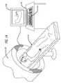
- FIG. 1Ais a simplified illustration of a patient undergoing imaging procedure.
- FIG. 1Bis a simplified illustration of the process for capturing the image of the patient's mouth and fabricating an implantable device having the features of the present invention.
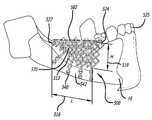
- FIGS. 2A and 2Bare simplified illustrations of an implantable device embodying features of the present invention disposed within a patient's mouth.
- FIG. 3is a simplified illustration of a process for exposing a patient's jaw bone by reflecting the gums and oral mucosa covering the bone.
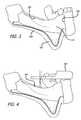
- FIG. 4is a simplified illustration of a step in a process for disposing an implantable device embodying features of the present invention in a patient's mouth, showing the disposal of a surgical guide in the patient's mouth.
- FIGS. 5 and 6are a simplified illustrations of steps in a process for disposing an implantable device embodying features of the present invention in a patient's mouth, showing the disposal of a device in the patient's mouth.
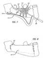
- FIG. 7is a simplified illustration of a step in a process for disposing an implantable device embodying features of the present invention in a patient's mouth, showing the application of bone graft substance onto and/or within cavities of the device.
- FIG. 8is a simplified illustration of a step in a process for disposing the device of FIG. 7 in a patient's mouth, showing the suturing of the flap.
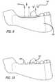
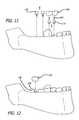
- FIG. 9is a simplified illustration of a step in a process for implanting the device of FIG. 8 in a patient's mouth, showing the removal of healing screws and placement of healing abutments.
- FIG. 10is a simplified illustration of a step in a process for implanting the device of FIG. 9 in a patient's mouth, showing healing abutments in place.
- FIG. 11is a simplified illustration of a step in a process for implanting the device of FIG. 10 in a patient's mouth, showing the removal of healing abutments.
- FIG. 12is a simplified illustration of a step in a process for implanting the device of FIG. 11 in a patient's mouth, showing the placement of crowns.
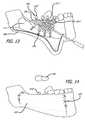
- FIG. 13is a simplified illustration of a step in a process for disposing an implantable device embodying features of the present invention in a patient's mouth, showing the application of bone graft substance onto and/or within cavities of the device, with abutments being integrated with the rig.
- FIG. 14is a simplified illustration of a step in a process for implanting the device of FIG. 13 in a patient's mouth, showing the suturing of the soft tissue flap.
- FIGS. 15A and 15Bare simplified side views of steps in a process for replacing bone and restoring function when the whole body of mandible or whole segment of the mandible is missing due to various reasons such as cancer, gunshot, facial trauma, etc.
- FIGS. 16A and 16 Bare front views of illustrations of FIGS. 15A and 15B .
- FIGS. 17A and 17 Bare top views of illustrations of FIGS. 15A and 15B .
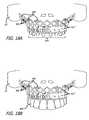
- FIGS. 18A and 18Bare simplified front views of steps in a process for restoring the aesthetic and function in atrophic jaw where all the teeth are missing.
- FIGS. 19A and 19 Bare side views of illustrations of FIGS. 18A and 18B .
- FIGS. 20A and 20 Bare top (occlusal) views of illustrations of FIGS. 18A and 18B .
- the present inventionrelates to devices and methods for implanting an implantable device in a patient's body.
- the deviceis a dental implant serving as a platform for placement of dental crowns and/or caps and/or fixed or removable prosthesis.
- a patient 10is identified needing a dental implant.
- the patientsuffers from total or substantial bone loss in the jaw.
- the physiciancommissions a three dimensional image 11 of the patient's anatomical area of interest using a 3D scanning tool 130 .
- the anatomical area of interestmay be the patient's mouth requiring such implant.
- the image and related informationmay be captured on a data storage 160 , either local or remote to the scanning tool.
- the image and related informationmay be displayed on a display 190 with a keyboard 210 providing the means for data and instructional communication between an operator and the scanning tool 130 .
- the imageis used to create a virtual implantable device.
- the commissioning and design, as for example shown in 13 of FIG. 1 B, of the suitable implantmay include the use of any appropriate tool including computer modeling.
- the fabrication of the implantis then commissioned, as for example shown in 15 of FIG. 1B .
- the virtual implantable deviceis thereafter used to create a 3D implantable device 500 (as shown in FIGS. 2A and 2B ), using techniques such as 3D laser printing.
- the implantmay be fabricated using other suitable methods, including, but not limited to, deposition or casting.
- a 3D laser printer 17used to fabricate the implantable device 500 .
- 3D printingis a form of additive manufacturing technology where a three dimensional object is created by laying down successive layers of material.
- 3D printersare generally faster, more affordable and easier to use than other additive manufacturing technologies.
- 3D printersoffer product developers the ability to print parts and assemblies made of several materials with different mechanical and physical properties in a single build process.
- Advanced 3D printing technologiesyield models that can serve as product prototypes. Using techniques and equipment such as 3D laser printers, great resolution, accuracy, and precision in the fabrication of the desired object can be obtained.
- the implant using methods embodying the present inventionwill be affixed within the patient, e.g., patient's mouth.
- an exemplary implantable device 500is shown as disposed in a subject's mouth.
- the implantable device 500includes a trabecular meshwork structure such as a rig 513 having a length 516 , a height 519 , a width 521 , a front edge (or rim) 524 , and back edge 527 , an outer edge or surface 535 , and an inner edge or surface 533 .
- the rig 513includes pluralities of girder-like structures 514 defining a plurality of cavities 515 therebetween. It should be noted that the term girder-like is not intended to be limited to elements which may form traditional triangular truss structures or elements and the network may take any suitable form or geometry as for example, the truss-like structures having curved elements such as struts in a cardiovascular stent.
- the nouns describing the various parts of the deviceare used for ease of reference and are as defined by the present inventor.
- the front edge 524refers to the side closest to the patient's lips
- back edge 527refers to the edge opposite the front edge
- outer edge surface 535to the side of the device facing the cheek of the patient
- the inner surface 533refers to the side of the device opposite the outer surface
- the length 516refers to the dimension extending from the front edge (e.g., front teeth 525 ) to the back edge 527 (toward the molar tooth)
- height 519refers to the dimension extending vertically in the direction from the lower jaw toward the roof of the mouth
- width 521refers to the dimension extending between the outer surface and the inner surface.
- the implant 500includes at least one bone fixation feature 540 for being operatively attachable to a bone surface 542 of the patient, and at least one cap (or similar coverings including crowns) receiving feature 546 (see for example, FIG. 13 ) for receiving one or more caps 549 (and/or crowns) thereon (See FIG. 14 ).
- the at least one bone fixation feature 540is configured for being fixedly attachable to the lower jawbone 16 of the patient and the at least one cap receiving feature 546 is opposite the at least one fixation feature 540 .
- a gum 522is incised by way of an incision 555 and reflected 558 exposing the jawbone 16 .
- a surgical guide 561is positioned on the teeth. Osteotomes 564 are drilled through the surgical guide 561 into the jawbone 16 . The surgical guide 561 is thereafter removed.
- a rig 513 ′such as a titanium rig, and incorporated with root-form implant 567 is then placed on the jawbone 16 .
- Fixating elements 560such as fixating screws, are used to fixate the rig 513 ′ onto the jawbone 16 on either or both the front and back of the jawbone. The fixating may occur in one or more places along the jawbone as appropriate.
- one or more fixating screws 560may be positioned through fixation ports 561 in outer surface 573 of the jawbone, on the inner surface 576 of the jawbone, front-portion of the jawbone, and/or backside-portion of the jawbone, or any other portion as may be necessary.
- One or more healing elementssuch as healing screws 579 are positioned in the rig 513 ′. As shown in FIG. 6 , a plurality of healing screws 579 are positioned on the top surface 582 of the rig (or the bottom surface if the rig were disposed on the upper jaw). The rig is secured in place as can be seen from FIGS. 5 and 6 , on both the outer and the inner potions of the jawbone.
- Bone graft substance 590is placed in and around the rig using appropriate tools such as surgical spatula 593 .
- the bone graft substance 590is particularly placed inside the cavities/cells 515 formed by the girders 514 .
- the bone graft substancecovers at least substantially the inside and the outside of the rig.
- the rigprovides scaffold, where the bone graft will conduct bone growth.
- Membrane 620is placed over, at least a substantial portion, of the rig to cover the rig and the bone graft substance. In the embodiment shown, the membrane at least substantially covers the healing screws 579 .
- the gum 522is then sutured in place using sutures 625 or other similar elements.
- FIGS. 9 and 10after passage of suitable period of time, for example 6 months, the healing screws 579 are exposed and removed.
- Healing abutments 630are placed on the rig 513 ′ where the healing screws 579 were previously located.
- the healing abutments 630are removed and permanent abutments 670 and crowns 549 are placed onto the rig 513 ′.
- Abutment fixating screws 673may be used to secure the permanent abutments 670 onto the rig 513 .
- the suturesmay also be removed at this time (or the sutures may of the disintegratable or resorbable type).
- a rig 513 ′′ incorporated with root-form implant 567 ′′ and abutments 670 ′′is placed on the jawbone 16 .
- Fixating screws 560are used to fixate the rig 513 ′′ on the jawbone.
- Bone graft substance 590is placed in and around the rig similar to that describe in relation to FIG. 7 .
- the rig 513 ′′provides a scaffold where the bone graft will conduct bone.
- Membrane 620is placed on top of the rig (and the incorporated abutments′′) and the bone graft.
- the gumis sutured in place using sutures 625 .
- the crowns 549are disposed on the abutments 670 ′′, all during the same surgical procedure.
- the rigwill eventually fuse with the jawbone over time.
- an exemplary implantable device 500is shown as disposed in a patient's mouth to replace a missing segment of the lower jaw (mandible) which may have been a result of any number of circumstances such as cancer, gun shot wound, or the like.
- the rig 513 ′′incorporated with root-form implant 567 ′′ and abutments 670 ′′, is disposed on the mandible bone 16 , after a portion of the gum has been excised and reflected.
- Fixating screws 560are used to fixate the rig 513 ′′ on the jawbone.
- Bone graft substance 590is placed in and around the rig similar to that describe in relation to FIGS. 13 and 14 .
- the rig 513 ′′provides a scaffold where the bone graft will conduce bone.
- Membrane 620(not shown) is placed on top of the rig (and the incorporated abutments′′) and the bone graft. The gum is sutured in place using sutures 625 .
- crowns 549are disposed on the abutments 670 ′′, all during the same surgical procedure.
- the rigwill eventually fuse with the jawbone over time.
- the crowns 549may be pre-disposed on the abutments 670 ′′ prior to the rig being disposed on the jawbone.
- the lower portion of the implantmay have a sufficiently large surface area in order to provide the necessary affixation of the implant to the jawbone.
- an exemplary implantable device 500is shown as disposed in a patient's mouth to replace missing teeth of a patient with severe to moderate bone loss on the edentulous upper jaw 16 ′′.
- Bone graftsmay be used in combination with the method and/or device herein. Bone grafts may also be used before and/or after the method and/or device described herein. There are several types of bone grafts, any of which may be used at any time sequence or frame of time in reference to the present invention. Bone grafts may be used wherein the bone to be grafted to the jaw is taken, or harvested, from the patient's own body. The area where the bone is harvested from, known as the donor site, is usually the mouth or the hip. This is the patient's own bone and is very compatible with his/her body. Autografts are generally the best graft technique and usually result in the greatest regeneration of missing jawbone.
- Allograftsare taken from human donors. Bone obtained in this manner undergoes rigorous tests and sterilization. The patient's body converts the donor bone into the patient's natural bone, thereby rebuilding his/her resorbed jawbone. Xenografts are harvested from animals. The animal bone, most commonly bovine (cow), is specially processed to make it biocompatible and sterile. It acts like a filler which in time the patient's body will replace with natural bone. After this replacement process is complete, dental implants may be placed to support the teeth. Alloplastic grafts are inert, man-made synthetic materials. The modern artificial joint replacement procedure uses metal alloplastic grafts. For bone replacement a man-made material that mimics natural bone is used.
- the patient's bodymay or may not replace the alloplastic graft with the patient's natural bone. In those cases where it is not replaced, it acts as a lattice or scaffold upon which natural bone is built. In either case, the end result is to create enough bone for the placement of dental implants.
- recombinant human bone morphogenetic proteine.g., available from Medtronic Corporation
- osteoblastbone forming cells
- Other types of bone grafting using recombinant DNA technologysuch as, for example, growth factors and/or morphogens may also be used.
- Root-form implantsmay be incorporated as part or parts of the method and/or device herein. Root form implant, when they are incorporated in the device or rig could be partially placed inside the present bone when the bone volume allows to aid in the primary retention and fixation of the device. Root-form implants may also be used in areas adjacent to where the device is placed before and/or after the method and/or device described herein. There are several types of root-form implants, any of which may be used at any time sequence or frame of time in reference to the present invention. Root-form implants may be the closest in shape and size to the natural tooth root. They are commonly used in wide, deep bone to provide a base for replacement of one, several or a complete arch of teeth.
- the healing periodusually varies from patient to patient and can be of any time length.
- the healing periodcan be two weeks, one month, six weeks, two months, ten weeks, three months, fourteen weeks, four months, eighteen weeks, five months, twenty-two weeks, six months, twenty-six weeks, seven months, thirty weeks, eight months, thirty-four weeks, nine months, thirty-eight weeks, ten months, forty-two weeks, eleven months, forty-six weeks, and a year.
- Plate-form implantsare usually used when the bone is so narrow that it may not be suitable for the root-form implant and the area is not suitable for bone grafting.
- the plate-form implantis flat and long so it can fit into the narrow jawbone. After application of anesthetic, the dentist will expose the area of the jawbone to be implanted and prepare the bone to accept the shape of the implant. The number of incisions depends upon the number of implants being placed. The implant is carefully set into place and the gums are closed with several stitches. Like root-form implants, there is usually a healing period for osseointegration, although some plate form implants are designed for immediate restoration.
- the plate form implant or implantscould be incorporated as part or parts of the rig.
- the plate formcould be implanted in the area adjacent to the area where the device is implanted before or after the device is implanted.
- the subperiosteal implantmay be prescribed.
- the subperiosteal implantis custom made and designed to sit on top of the bone, but under the gums. There are two methods for its placement.
- the dentistwill expose the jawbone and take an impression or model of the bone using special materials.
- This modelis used by a dental laboratory to carefully create the custom implant to fit the patient's jaw.
- a second procedureis then carried out where the jawbone is exposed and the implant placed.
- the gumsare closed with several stitches and replacement teeth are put into place.
- the dentistwill order a special CAT scan of the patient's jawbone.
- a model of the jawboneis constructed. This model is used by a dental laboratory to fabricate the custom subperiosteal implant to fit the patient's jaw.
- a surgical procedureis then carried out where the jawbone is exposed and the implant placed. The gums are closed with several stitches and the replacement teeth are put into place.
Landscapes
- Health & Medical Sciences (AREA)
- Life Sciences & Earth Sciences (AREA)
- Oral & Maxillofacial Surgery (AREA)
- Animal Behavior & Ethology (AREA)
- General Health & Medical Sciences (AREA)
- Public Health (AREA)
- Veterinary Medicine (AREA)
- Epidemiology (AREA)
- Engineering & Computer Science (AREA)
- Orthopedic Medicine & Surgery (AREA)
- Dentistry (AREA)
- Biomedical Technology (AREA)
- Heart & Thoracic Surgery (AREA)
- Plastic & Reconstructive Surgery (AREA)
- Medical Informatics (AREA)
- Transplantation (AREA)
- Vascular Medicine (AREA)
- Cardiology (AREA)
- Physics & Mathematics (AREA)
- Optics & Photonics (AREA)
- Molecular Biology (AREA)
- High Energy & Nuclear Physics (AREA)
- Pathology (AREA)
- Radiology & Medical Imaging (AREA)
- Biophysics (AREA)
- Nuclear Medicine, Radiotherapy & Molecular Imaging (AREA)
- Surgery (AREA)
- Developmental Biology & Embryology (AREA)
- Neurosurgery (AREA)
- Inorganic Chemistry (AREA)
- Chemical & Material Sciences (AREA)
- Pulmonology (AREA)
- Manufacturing & Machinery (AREA)
- Theoretical Computer Science (AREA)
- Prostheses (AREA)
- Dental Prosthetics (AREA)
Abstract
Description
Claims (11)
Priority Applications (16)
| Application Number | Priority Date | Filing Date | Title |
|---|---|---|---|
| US13/335,371US8485820B1 (en) | 2011-12-22 | 2011-12-22 | Devices and methods for enhancing bone growth |
| AU2012358904AAU2012358904A1 (en) | 2011-12-22 | 2012-12-20 | Devices and methods for enhancing bone growth |
| EP12859870.3AEP2793734B1 (en) | 2011-12-22 | 2012-12-20 | Dental device for enhancing bone growth |
| CN201280064035.0ACN103997985A (en) | 2011-12-22 | 2012-12-20 | Device and method for enhancing bone growth |
| MX2014007503AMX2014007503A (en) | 2011-12-22 | 2012-12-20 | Devices and methods for enhancing bone growth. |
| KR1020147020597AKR20140113982A (en) | 2011-12-22 | 2012-12-20 | Devices and methods for enhancing bone growth |
| EP17181413.0AEP3263065A1 (en) | 2011-12-22 | 2012-12-20 | Devices and methods for enhancing bone growth |
| US14/367,908US9308060B2 (en) | 2011-12-22 | 2012-12-20 | Devices and methods for enhancing bone growth |
| PCT/US2012/070886WO2013096592A1 (en) | 2011-12-22 | 2012-12-20 | Devices and methods for enhancing bone growth |
| CA2859662ACA2859662A1 (en) | 2011-12-22 | 2012-12-20 | Devices and methods for enhancing bone growth |
| JP2014548880AJP2015507491A (en) | 2011-12-22 | 2012-12-20 | Devices and methods for enhancing bone growth |
| BR112014015268ABR112014015268A8 (en) | 2011-12-22 | 2012-12-20 | implantable dental device and method to implant in a patient's mouth |
| US13/919,827US8888485B2 (en) | 2011-12-22 | 2013-06-17 | Devices and methods for enhancing bone growth |
| IL233235AIL233235A0 (en) | 2011-12-22 | 2014-06-18 | Devices and methods for enhancing bone growth |
| IN4602CHN2014IN2014CN04602A (en) | 2011-12-22 | 2014-06-18 | |
| US14/512,403US9649178B2 (en) | 2011-12-22 | 2014-10-11 | Devices and methods for enhancing bone growth |
Applications Claiming Priority (1)
| Application Number | Priority Date | Filing Date | Title |
|---|---|---|---|
| US13/335,371US8485820B1 (en) | 2011-12-22 | 2011-12-22 | Devices and methods for enhancing bone growth |
Related Child Applications (2)
| Application Number | Title | Priority Date | Filing Date |
|---|---|---|---|
| US14/367,908ContinuationUS9308060B2 (en) | 2011-12-22 | 2012-12-20 | Devices and methods for enhancing bone growth |
| US13/919,827ContinuationUS8888485B2 (en) | 2011-12-22 | 2013-06-17 | Devices and methods for enhancing bone growth |
Publications (2)
| Publication Number | Publication Date |
|---|---|
| US20130164707A1 US20130164707A1 (en) | 2013-06-27 |
| US8485820B1true US8485820B1 (en) | 2013-07-16 |
Family
ID=48654901
Family Applications (4)
| Application Number | Title | Priority Date | Filing Date |
|---|---|---|---|
| US13/335,371Expired - Fee RelatedUS8485820B1 (en) | 2011-12-22 | 2011-12-22 | Devices and methods for enhancing bone growth |
| US14/367,908Expired - Fee RelatedUS9308060B2 (en) | 2011-12-22 | 2012-12-20 | Devices and methods for enhancing bone growth |
| US13/919,827ActiveUS8888485B2 (en) | 2011-12-22 | 2013-06-17 | Devices and methods for enhancing bone growth |
| US14/512,403Expired - Fee RelatedUS9649178B2 (en) | 2011-12-22 | 2014-10-11 | Devices and methods for enhancing bone growth |
Family Applications After (3)
| Application Number | Title | Priority Date | Filing Date |
|---|---|---|---|
| US14/367,908Expired - Fee RelatedUS9308060B2 (en) | 2011-12-22 | 2012-12-20 | Devices and methods for enhancing bone growth |
| US13/919,827ActiveUS8888485B2 (en) | 2011-12-22 | 2013-06-17 | Devices and methods for enhancing bone growth |
| US14/512,403Expired - Fee RelatedUS9649178B2 (en) | 2011-12-22 | 2014-10-11 | Devices and methods for enhancing bone growth |
Country Status (12)
| Country | Link |
|---|---|
| US (4) | US8485820B1 (en) |
| EP (2) | EP3263065A1 (en) |
| JP (1) | JP2015507491A (en) |
| KR (1) | KR20140113982A (en) |
| CN (1) | CN103997985A (en) |
| AU (1) | AU2012358904A1 (en) |
| BR (1) | BR112014015268A8 (en) |
| CA (1) | CA2859662A1 (en) |
| IL (1) | IL233235A0 (en) |
| IN (1) | IN2014CN04602A (en) |
| MX (1) | MX2014007503A (en) |
| WO (1) | WO2013096592A1 (en) |
Cited By (33)
| Publication number | Priority date | Publication date | Assignee | Title |
|---|---|---|---|---|
| US20140038132A1 (en)* | 2012-07-31 | 2014-02-06 | Zimmer Trabecular Metal Technology, Inc. | Dental regenerative device made of porous metal |
| US20160113748A1 (en)* | 2014-10-24 | 2016-04-28 | Alfredo Villa | Dental prosthesis for cattle |
| US9539069B2 (en) | 2012-04-26 | 2017-01-10 | Zimmer Dental, Inc. | Dental implant wedges |
| US9545302B2 (en) | 2013-11-20 | 2017-01-17 | Dermagenesis Llc | Skin printing and auto-grafting |
| US9554877B2 (en)* | 2012-07-31 | 2017-01-31 | Zimmer, Inc. | Dental regenerative device made of porous metal |
| US20170312057A1 (en)* | 2016-04-29 | 2017-11-02 | Jung-Chuan CHENG | Tooth implantation technique and a subperiosteal implant manufacturing method for the solution of extreme atrophy of a tooth bone |
| US9861482B2 (en)* | 2008-08-26 | 2018-01-09 | Andy Boiangiu | Dental bone implant and implant method |
| US20190000628A1 (en)* | 2011-02-28 | 2019-01-03 | DePuy Synthes Products, Inc. | Modular tissue scaffolds |
| US10183442B1 (en) | 2018-03-02 | 2019-01-22 | Additive Device, Inc. | Medical devices and methods for producing the same |
| US10357367B2 (en)* | 2017-09-11 | 2019-07-23 | DePuy Synthes Products, Inc. | Patient-specific mandible graft cage |
| USD870889S1 (en) | 2018-03-02 | 2019-12-24 | Restor3D, Inc. | Cutout airway stent |
| USD870888S1 (en) | 2018-03-02 | 2019-12-24 | Restor3D, Inc. | Accordion airway stent |
| USD870890S1 (en) | 2018-03-02 | 2019-12-24 | Restor3D, Inc. | Spiral airway stent |
| US10517737B2 (en) | 2015-05-22 | 2019-12-31 | Stryker European Operations Limited | Joint or segmental bone implant for deformity correction |
| USD871577S1 (en) | 2018-03-02 | 2019-12-31 | Restor3D, Inc. | Studded airway stent |
| CN110891520A (en)* | 2017-07-10 | 2020-03-17 | 卡尔·莱宾格医疗技术有限责任两合公司 | Bone augmentation element and kit of bone augmentation elements with inserted (dental) implants |
| US10688726B2 (en)* | 2014-03-04 | 2020-06-23 | Royal Melbourne Institute Of Technology | Method for producing a customised orthopaedic implant |
| US20200205984A1 (en)* | 2018-12-26 | 2020-07-02 | Medyssey Co., Ltd. | Patient-specific mandibular implant inserted into mandibular defect region and method of manufacturing the same |
| US10772732B1 (en) | 2020-01-08 | 2020-09-15 | Restor3D, Inc. | Sheet based triply periodic minimal surface implants for promoting osseointegration and methods for producing same |
| US10828108B2 (en) | 2015-06-25 | 2020-11-10 | Buck Medical Research Ltd. | Orthopaedic or biologic support structure, methods of making and methods of use |
| US10889053B1 (en) | 2019-03-25 | 2021-01-12 | Restor3D, Inc. | Custom surgical devices and method for manufacturing the same |
| USD920516S1 (en) | 2020-01-08 | 2021-05-25 | Restor3D, Inc. | Osteotomy wedge |
| USD920517S1 (en) | 2020-01-08 | 2021-05-25 | Restor3D, Inc. | Osteotomy wedge |
| USD920515S1 (en) | 2020-01-08 | 2021-05-25 | Restor3D, Inc. | Spinal implant |
| US11123162B2 (en) | 2015-08-14 | 2021-09-21 | Nt-Trading Gmbh & Co. Kg | Method for producing an anatomical dental implant |
| US20220031430A1 (en)* | 2019-02-15 | 2022-02-03 | Dae Kyung LEE | Dental implant and surgery guide therefor |
| US11540900B2 (en) | 2018-05-03 | 2023-01-03 | The United States Of America As Represented By The Secretary Of The Navy | Dental ridge augmentation matrix with integrated dental implant surgical drill guide system |
| US11806028B1 (en) | 2022-10-04 | 2023-11-07 | Restor3D, Inc. | Surgical guides and processes for producing and using the same |
| US11850144B1 (en) | 2022-09-28 | 2023-12-26 | Restor3D, Inc. | Ligament docking implants and processes for making and using same |
| US11960266B1 (en) | 2023-08-23 | 2024-04-16 | Restor3D, Inc. | Patient-specific medical devices and additive manufacturing processes for producing the same |
| USD1051384S1 (en) | 2023-03-24 | 2024-11-12 | Restor3D, Inc. | Bone fixation pin |
| USD1052732S1 (en) | 2023-05-25 | 2024-11-26 | Restor3D, Inc. | Subtalar wedge |
| USD1053353S1 (en) | 2023-03-24 | 2024-12-03 | Restor3D, Inc. | Orthopedic screw |
Families Citing this family (52)
| Publication number | Priority date | Publication date | Assignee | Title |
|---|---|---|---|---|
| TWI532469B (en)* | 2011-12-23 | 2016-05-11 | 奧齒泰有限責任公司 | Dental membrane |
| WO2013120067A1 (en)* | 2012-02-09 | 2013-08-15 | Osseous Technologies Of America | Biocompatible containment member for bone augmentation surgery made of processed natural membrane from an animal donor |
| US10405945B2 (en) | 2013-03-14 | 2019-09-10 | National Dentex, Llc | Bone foundation guide and method of use |
| US10639129B2 (en) | 2013-03-14 | 2020-05-05 | National Dentex, Llc | Bone foundation guide system and method |
| US10278789B2 (en) | 2013-03-14 | 2019-05-07 | National Dentex, Llc | Bone foundation guide system and method |
| US10398530B2 (en) | 2013-03-14 | 2019-09-03 | National Dentex, Llc | Bone foundation guide system and method |
| US10307226B2 (en) | 2013-03-14 | 2019-06-04 | National Dentex, Llc | Bone foundation guide and method of use |
| US20160250002A1 (en)* | 2013-10-15 | 2016-09-01 | Marvin Cota | One Piece Custom Made Dental Device For Holding Multiple Teeth |
| CN104665905B (en) | 2013-11-26 | 2018-04-06 | 财团法人工业技术研究院 | Bionic fixing device |
| CN104665906B (en) | 2013-11-26 | 2017-09-08 | 财团法人工业技术研究院 | Bionic fixing device |
| CN104665913B (en) | 2013-11-26 | 2017-06-06 | 财团法人工业技术研究院 | Bionic fixing device and pulling-out device thereof |
| CN103637862B (en)* | 2013-12-18 | 2015-12-23 | 北京爱康宜诚医疗器材股份有限公司 | Jawbone recovery support |
| ES2544904B1 (en)* | 2014-03-04 | 2016-07-07 | Francisco Javier RUIZ GINER | DENTAL ARTIFICIAL GRAFT |
| WO2015138657A1 (en) | 2014-03-11 | 2015-09-17 | Ohio State Innovation Foundation | Methods, devices, and manufacture of the devices for musculoskeletal reconstructive surgery |
| JP2016033959A (en)* | 2014-07-31 | 2016-03-10 | 株式会社東芝 | Load tap changer and load switch for load tap changer |
| JP2016033940A (en)* | 2014-07-31 | 2016-03-10 | 株式会社東芝 | Gas insulated transformer |
| TWI548429B (en) | 2014-11-07 | 2016-09-11 | 財團法人工業技術研究院 | Medical composite material method for fabricating the same and applications thereof |
| US10751100B2 (en) | 2014-12-17 | 2020-08-25 | Medartis Holding Ag | Bone screws and surgical sets comprising bone screws |
| JP6605607B2 (en) | 2014-12-17 | 2019-11-13 | メダルティス・ホールディング・アクチェンゲゼルシャフト | Bone plate, surgical set and reconstruction set |
| EP3087954B1 (en)* | 2015-04-27 | 2019-01-30 | Peter Kessler | Jaw bone transplant arrangement |
| US10449017B2 (en)* | 2015-06-08 | 2019-10-22 | Cadskills Bvba | Subperiosteal jaw implant |
| WO2016201580A1 (en)* | 2015-06-18 | 2016-12-22 | Panthera Dental Inc. | Method and system for generating a model of a subperiosteal dental implant device and customized implant head |
| US20170007359A1 (en) | 2015-07-07 | 2017-01-12 | Align Technology, Inc. | Direct fabrication of orthodontic appliances with variable properties |
| EP3364908A1 (en) | 2015-10-23 | 2018-08-29 | Daniel R. Llop | Bone foundation guide system and method |
| US10898332B2 (en)* | 2015-11-24 | 2021-01-26 | Ossdsign Ab | Bone implants and methods for correcting bone defects |
| TWI587847B (en)* | 2015-12-07 | 2017-06-21 | 財團法人工業技術研究院 | Implant device for osseous integration |
| DE102015122800B3 (en)* | 2015-12-23 | 2017-05-11 | Karl Leibinger Medizintechnik Gmbh & Co. Kg | Bone structure adapted molded implant with socket and associated manufacturing process |
| CN106994054A (en)* | 2016-01-22 | 2017-08-01 | 郑荣川 | Novel manufacturing method of subperiosteal implant |
| BR112018015139A2 (en) | 2016-01-28 | 2018-12-18 | Depuy Synthes Products Inc | graft containment cage separation accessory |
| EP3407837B1 (en)* | 2016-01-28 | 2021-07-07 | DePuy Synthes Products, Inc. | Helical bone graft containment cage |
| CA3015801A1 (en) | 2016-03-05 | 2017-09-14 | National Dentex, Llc | Bone foundation guide system and method |
| KR101774149B1 (en) | 2016-03-23 | 2017-09-04 | 가톨릭대학교 산학협력단 | Method for manufacturing implant using implant -scaffold assembled type |
| CN105769362B (en)* | 2016-04-26 | 2018-10-09 | 中山大学孙逸仙纪念医院 | Guiding device for the 3D printing that Dental implantion and mandibular integration are rebuild |
| FR3057458B1 (en)* | 2016-10-19 | 2018-11-16 | Anthogyr | ASSEMBLY FOR PREPARING A DENTAL PROSTHESIS |
| IT201600118979A1 (en)* | 2016-11-24 | 2018-05-24 | Eaglegrid S R L Via Rossini 19 24129 Bergamo Bg | Method of production of a grid of a Juxtaoxian implant |
| CN107009612A (en)* | 2017-06-07 | 2017-08-04 | 珠海天威飞马打印耗材有限公司 | The forming method of the threedimensional model of threedimensional model and rejected region |
| KR102294050B1 (en)* | 2017-06-13 | 2021-08-25 | 가톨릭대학교 산학협력단 | Artificial tooth structure manufacturing method by 3D printing and Artificial tooth structure manufactured by the method |
| DE102017115403A1 (en)* | 2017-07-10 | 2019-01-10 | Karl Leibinger Medizintechnik Gmbh & Co. Kg | Bioresorbable bone implant and manufacturing process |
| KR101984703B1 (en)* | 2017-08-14 | 2019-05-31 | 한국생산기술연구원 | Artificial bone having flexible mesh structure and method for manufacturing the same |
| CN108078655B (en)* | 2017-12-13 | 2019-10-25 | 重庆医科大学附属口腔医院 | Mandibular bionic implant and preparation method thereof |
| EP3768191A4 (en)* | 2018-03-21 | 2021-12-15 | Panthera Dental Inc. | SUBPERIOSTAL DENTAL IMPLANT |
| CN108720949B (en)* | 2018-04-02 | 2024-09-27 | 成都登特牙科技术开发有限公司 | Support structure for dental additive manufacturing |
| CN108888379A (en)* | 2018-08-15 | 2018-11-27 | 重庆医科大学附属口腔医院 | Bone increment support structure and preparation method thereof |
| CN109662807A (en)* | 2019-01-15 | 2019-04-23 | 上海交通大学医学院附属第九人民医院 | A kind of titanium net implants of the personalized Level of Alveolar Bone increment generated using three-dimensional printing technology |
| US11123163B2 (en)* | 2019-04-04 | 2021-09-21 | Dentsply Sirona Inc. | Custom dental membrane |
| CN110613533B (en)* | 2019-09-23 | 2023-11-07 | 浙江工业大学 | PEKK personalized implant design and production method and implant for repair of mandibular box-shaped defect |
| TWI716156B (en)* | 2019-10-18 | 2021-01-11 | 財團法人工業技術研究院 | Mandibular reconstruction prosthesis |
| US20210145549A1 (en)* | 2019-11-14 | 2021-05-20 | Biomet 3I, Llc | Implant placement assist system |
| CN111202608A (en)* | 2020-02-27 | 2020-05-29 | 广州市健齿生物科技有限公司 | Repair titanium mesh for alveolar bone grafting and preparation method thereof |
| WO2022057994A1 (en)* | 2020-09-16 | 2022-03-24 | Ayad Seif Eldein Mohamed Kamel | Computer aided design computer aided manufacturing milled titanium restoration as a graft for the lost dental bone |
| CN112472334B (en)* | 2020-11-25 | 2021-10-29 | 广州市弘健生物医用制品科技有限公司 | A scaffold structure for alveolar bone reconstruction |
| US20230210639A1 (en)* | 2021-12-31 | 2023-07-06 | Biomet 3I, Llc | Dental support screw |
Citations (14)
| Publication number | Priority date | Publication date | Assignee | Title |
|---|---|---|---|---|
| US5006070A (en)* | 1989-02-27 | 1991-04-09 | Shigeru Komatsu | Dental implant with y-shaped body |
| US5306149A (en)* | 1991-07-15 | 1994-04-26 | Institut Straumann Ag | Implant for attaching a substitute tooth or the like to a jaw |
| US5769637A (en)* | 1996-05-22 | 1998-06-23 | Sofamor Danek Properties, Inc. | Dental implant and alveolar process augmentation structures and method of installation |
| US6030218A (en) | 1999-04-12 | 2000-02-29 | Robinson; Dane Q. | Osseo-integrated sub-periosteal implant |
| US6328765B1 (en) | 1998-12-03 | 2001-12-11 | Gore Enterprise Holdings, Inc. | Methods and articles for regenerating living tissue |
| US6379962B1 (en) | 1997-11-14 | 2002-04-30 | Bonetec Corporation | Polymer scaffold having microporous polymer struts defining interconnected macropores |
| US20050010304A1 (en) | 2003-06-16 | 2005-01-13 | Jamali Amir Ali | Device and method for reconstruction of osseous skeletal defects |
| US20070248933A1 (en) | 2003-10-10 | 2007-10-25 | Dentigenix Inc. | Methods for treating dental conditions using tissue scaffolds |
| US20070269769A1 (en) | 2006-05-18 | 2007-11-22 | Marcello Marchesi | Method for the guided regeneration of bone and/or periodontal tissues in the medical surgical and dental field and device thus obtainable |
| US20090215007A1 (en) | 2005-05-04 | 2009-08-27 | Richard Caterini | Dental implant with porous trabecular structure |
| US20090291415A1 (en) | 2006-07-05 | 2009-11-26 | Medintal Ltd | Device and Method for Gingival Attachment Associated with Endosseous Implants |
| US20100137990A1 (en) | 2007-02-20 | 2010-06-03 | National University Of Ireland, Galway | Porous Substrates for Implantation |
| US20100161061A1 (en)* | 2008-12-18 | 2010-06-24 | Jessee Hunt | Truss implant |
| US20100256773A1 (en) | 2007-07-03 | 2010-10-07 | Vlaamse Instelling Voor Technologisch Onderzoek N.V. (Vito) | Surgical implant composed of a porous core and a dense surface layer |
Family Cites Families (7)
| Publication number | Priority date | Publication date | Assignee | Title |
|---|---|---|---|---|
| US5433607A (en)* | 1991-07-15 | 1995-07-18 | Institut Straumann Ag | Implant for attaching a substitute tooth or the like to a jaw |
| DE4242889A1 (en)* | 1992-12-18 | 1994-06-23 | Merck Patent Gmbh | Hollow endoprostheses with filling that promotes bone growth |
| US20060147332A1 (en)* | 2004-12-30 | 2006-07-06 | Howmedica Osteonics Corp. | Laser-produced porous structure |
| US20050192675A1 (en)* | 2004-03-01 | 2005-09-01 | Robinson Dane Q. | Device for use in stimulating bone growth |
| ITUD20040213A1 (en)* | 2004-11-12 | 2005-02-12 | Oralplant Srl | MEDICAL DEVICE FOR REGENERATION E |
| WO2008095332A1 (en)* | 2007-02-01 | 2008-08-14 | Lucky 5-7 Corporation Limited | Denture carrier fixed on the surface of jawbone |
| US20100291508A1 (en)* | 2009-05-13 | 2010-11-18 | Jensen Ole T | Biocompatible shell for bone treatment |
- 2011
- 2011-12-22USUS13/335,371patent/US8485820B1/ennot_activeExpired - Fee Related
- 2012
- 2012-12-20MXMX2014007503Apatent/MX2014007503A/ennot_activeApplication Discontinuation
- 2012-12-20USUS14/367,908patent/US9308060B2/ennot_activeExpired - Fee Related
- 2012-12-20WOPCT/US2012/070886patent/WO2013096592A1/enactiveApplication Filing
- 2012-12-20BRBR112014015268Apatent/BR112014015268A8/ennot_activeIP Right Cessation
- 2012-12-20AUAU2012358904Apatent/AU2012358904A1/ennot_activeAbandoned
- 2012-12-20CNCN201280064035.0Apatent/CN103997985A/enactivePending
- 2012-12-20EPEP17181413.0Apatent/EP3263065A1/ennot_activeWithdrawn
- 2012-12-20JPJP2014548880Apatent/JP2015507491A/enactivePending
- 2012-12-20EPEP12859870.3Apatent/EP2793734B1/ennot_activeNot-in-force
- 2012-12-20KRKR1020147020597Apatent/KR20140113982A/ennot_activeWithdrawn
- 2012-12-20CACA2859662Apatent/CA2859662A1/ennot_activeAbandoned
- 2013
- 2013-06-17USUS13/919,827patent/US8888485B2/enactiveActive
- 2014
- 2014-06-18ILIL233235Apatent/IL233235A0/enunknown
- 2014-06-18ININ4602CHN2014patent/IN2014CN04602A/enunknown
- 2014-10-11USUS14/512,403patent/US9649178B2/ennot_activeExpired - Fee Related
Patent Citations (14)
| Publication number | Priority date | Publication date | Assignee | Title |
|---|---|---|---|---|
| US5006070A (en)* | 1989-02-27 | 1991-04-09 | Shigeru Komatsu | Dental implant with y-shaped body |
| US5306149A (en)* | 1991-07-15 | 1994-04-26 | Institut Straumann Ag | Implant for attaching a substitute tooth or the like to a jaw |
| US5769637A (en)* | 1996-05-22 | 1998-06-23 | Sofamor Danek Properties, Inc. | Dental implant and alveolar process augmentation structures and method of installation |
| US6379962B1 (en) | 1997-11-14 | 2002-04-30 | Bonetec Corporation | Polymer scaffold having microporous polymer struts defining interconnected macropores |
| US6328765B1 (en) | 1998-12-03 | 2001-12-11 | Gore Enterprise Holdings, Inc. | Methods and articles for regenerating living tissue |
| US6030218A (en) | 1999-04-12 | 2000-02-29 | Robinson; Dane Q. | Osseo-integrated sub-periosteal implant |
| US20050010304A1 (en) | 2003-06-16 | 2005-01-13 | Jamali Amir Ali | Device and method for reconstruction of osseous skeletal defects |
| US20070248933A1 (en) | 2003-10-10 | 2007-10-25 | Dentigenix Inc. | Methods for treating dental conditions using tissue scaffolds |
| US20090215007A1 (en) | 2005-05-04 | 2009-08-27 | Richard Caterini | Dental implant with porous trabecular structure |
| US20070269769A1 (en) | 2006-05-18 | 2007-11-22 | Marcello Marchesi | Method for the guided regeneration of bone and/or periodontal tissues in the medical surgical and dental field and device thus obtainable |
| US20090291415A1 (en) | 2006-07-05 | 2009-11-26 | Medintal Ltd | Device and Method for Gingival Attachment Associated with Endosseous Implants |
| US20100137990A1 (en) | 2007-02-20 | 2010-06-03 | National University Of Ireland, Galway | Porous Substrates for Implantation |
| US20100256773A1 (en) | 2007-07-03 | 2010-10-07 | Vlaamse Instelling Voor Technologisch Onderzoek N.V. (Vito) | Surgical implant composed of a porous core and a dense surface layer |
| US20100161061A1 (en)* | 2008-12-18 | 2010-06-24 | Jessee Hunt | Truss implant |
Non-Patent Citations (4)
| Title |
|---|
| PCT, International Search Report and The Written Opinion of the International Searching Authority, on the PCT Counterpart of the present application (PCT/US2012/070886, dated Feb. 25, 2013-9 pages). |
| PCT, International Search Report and The Written Opinion of the International Searching Authority, on the PCT Counterpart of the present application (PCT/US2012/070886, dated Feb. 25, 2013—9 pages). |
| Zimmer Holding, Inc., Clinical Advantages of Trabecular Metal(TM) Technology Demonstrated in New Studies http://www.zimmer.com/en-US/hcp/news/news-02-2011-clinical-advantages-of-trabecular-metal.jspx, Feb. 17, 2011, San Diego, CA. |
| Zimmer Holding, Inc., Clinical Advantages of Trabecular Metal™ Technology Demonstrated in New Studies http://www.zimmer.com/en-US/hcp/news/news-02-2011-clinical-advantages-of-trabecular-metal.jspx, Feb. 17, 2011, San Diego, CA. |
Cited By (51)
| Publication number | Priority date | Publication date | Assignee | Title |
|---|---|---|---|---|
| US9861482B2 (en)* | 2008-08-26 | 2018-01-09 | Andy Boiangiu | Dental bone implant and implant method |
| US10500053B2 (en)* | 2011-02-28 | 2019-12-10 | DePuy Synthes Products, Inc. | Modular tissue scaffolds |
| US12023251B2 (en) | 2011-02-28 | 2024-07-02 | DePuy Synthes Products, Inc. | Modular tissue scaffolds |
| US20190000628A1 (en)* | 2011-02-28 | 2019-01-03 | DePuy Synthes Products, Inc. | Modular tissue scaffolds |
| US11793644B2 (en) | 2011-02-28 | 2023-10-24 | DePuy Synthes Products, Inc. | Modular tissue scaffolds |
| US9539069B2 (en) | 2012-04-26 | 2017-01-10 | Zimmer Dental, Inc. | Dental implant wedges |
| US10517698B2 (en) | 2012-04-26 | 2019-12-31 | Zimmer Dental, Inc. | Dental implant wedges |
| US20140038132A1 (en)* | 2012-07-31 | 2014-02-06 | Zimmer Trabecular Metal Technology, Inc. | Dental regenerative device made of porous metal |
| US9554877B2 (en)* | 2012-07-31 | 2017-01-31 | Zimmer, Inc. | Dental regenerative device made of porous metal |
| US9545302B2 (en) | 2013-11-20 | 2017-01-17 | Dermagenesis Llc | Skin printing and auto-grafting |
| US10688726B2 (en)* | 2014-03-04 | 2020-06-23 | Royal Melbourne Institute Of Technology | Method for producing a customised orthopaedic implant |
| US9566142B2 (en)* | 2014-10-24 | 2017-02-14 | Alfredo Villa | Dental prosthesis for cattle |
| US20160113748A1 (en)* | 2014-10-24 | 2016-04-28 | Alfredo Villa | Dental prosthesis for cattle |
| US11395747B2 (en) | 2015-05-22 | 2022-07-26 | Stryker European Operations Limited | Joint or segmental bone implant for deformity correction |
| US11759332B2 (en) | 2015-05-22 | 2023-09-19 | Stryker European Operations Limited | Joint or segmental bone implant for deformity correction |
| US10517737B2 (en) | 2015-05-22 | 2019-12-31 | Stryker European Operations Limited | Joint or segmental bone implant for deformity correction |
| US10828108B2 (en) | 2015-06-25 | 2020-11-10 | Buck Medical Research Ltd. | Orthopaedic or biologic support structure, methods of making and methods of use |
| US11123162B2 (en) | 2015-08-14 | 2021-09-21 | Nt-Trading Gmbh & Co. Kg | Method for producing an anatomical dental implant |
| US20170312057A1 (en)* | 2016-04-29 | 2017-11-02 | Jung-Chuan CHENG | Tooth implantation technique and a subperiosteal implant manufacturing method for the solution of extreme atrophy of a tooth bone |
| CN110891520A (en)* | 2017-07-10 | 2020-03-17 | 卡尔·莱宾格医疗技术有限责任两合公司 | Bone augmentation element and kit of bone augmentation elements with inserted (dental) implants |
| US20190290436A1 (en)* | 2017-09-11 | 2019-09-26 | DePuy Synthes Products, Inc. | Patient-specific mandible graft cage |
| US10357367B2 (en)* | 2017-09-11 | 2019-07-23 | DePuy Synthes Products, Inc. | Patient-specific mandible graft cage |
| US10850442B1 (en) | 2018-03-02 | 2020-12-01 | Restor3D, Inc. | Medical devices and methods for producing the same |
| USD870888S1 (en) | 2018-03-02 | 2019-12-24 | Restor3D, Inc. | Accordion airway stent |
| US10183442B1 (en) | 2018-03-02 | 2019-01-22 | Additive Device, Inc. | Medical devices and methods for producing the same |
| USD870889S1 (en) | 2018-03-02 | 2019-12-24 | Restor3D, Inc. | Cutout airway stent |
| USD870890S1 (en) | 2018-03-02 | 2019-12-24 | Restor3D, Inc. | Spiral airway stent |
| USD871577S1 (en) | 2018-03-02 | 2019-12-31 | Restor3D, Inc. | Studded airway stent |
| US11540900B2 (en) | 2018-05-03 | 2023-01-03 | The United States Of America As Represented By The Secretary Of The Navy | Dental ridge augmentation matrix with integrated dental implant surgical drill guide system |
| US20200205984A1 (en)* | 2018-12-26 | 2020-07-02 | Medyssey Co., Ltd. | Patient-specific mandibular implant inserted into mandibular defect region and method of manufacturing the same |
| US11701230B2 (en)* | 2018-12-26 | 2023-07-18 | Medyssey Co., Ltd. | Patient-specific mandibular implant inserted into mandibular defect region and method of manufacturing the same |
| US20220031430A1 (en)* | 2019-02-15 | 2022-02-03 | Dae Kyung LEE | Dental implant and surgery guide therefor |
| US10889053B1 (en) | 2019-03-25 | 2021-01-12 | Restor3D, Inc. | Custom surgical devices and method for manufacturing the same |
| US11484413B1 (en) | 2020-01-08 | 2022-11-01 | Restor3D, Inc. | Sheet based triply periodic minimal surface implants for promoting osseointegration and methods for producing same |
| USD1013876S1 (en) | 2020-01-08 | 2024-02-06 | Restor3D, Inc. | Osteotomy wedge |
| USD992116S1 (en) | 2020-01-08 | 2023-07-11 | Restor3D, Inc. | Osteotomy wedge |
| USD920516S1 (en) | 2020-01-08 | 2021-05-25 | Restor3D, Inc. | Osteotomy wedge |
| US10772732B1 (en) | 2020-01-08 | 2020-09-15 | Restor3D, Inc. | Sheet based triply periodic minimal surface implants for promoting osseointegration and methods for producing same |
| USD920517S1 (en) | 2020-01-08 | 2021-05-25 | Restor3D, Inc. | Osteotomy wedge |
| USD1071220S1 (en) | 2020-01-08 | 2025-04-15 | Restor3D, Inc. | Osteotomy wedge |
| US11026798B1 (en) | 2020-01-08 | 2021-06-08 | Restor3D, Inc. | Sheet based triply periodic minimal surface implants for promoting osseointegration and methods for producing same |
| USD1013875S1 (en) | 2020-01-08 | 2024-02-06 | Restor3D, Inc. | Spinal implant |
| USD920515S1 (en) | 2020-01-08 | 2021-05-25 | Restor3D, Inc. | Spinal implant |
| US11850144B1 (en) | 2022-09-28 | 2023-12-26 | Restor3D, Inc. | Ligament docking implants and processes for making and using same |
| US12042159B1 (en) | 2022-10-04 | 2024-07-23 | Restor3D, Inc. | Surgical guides and processes for producing and using the same |
| US11806028B1 (en) | 2022-10-04 | 2023-11-07 | Restor3D, Inc. | Surgical guides and processes for producing and using the same |
| USD1051384S1 (en) | 2023-03-24 | 2024-11-12 | Restor3D, Inc. | Bone fixation pin |
| USD1053353S1 (en) | 2023-03-24 | 2024-12-03 | Restor3D, Inc. | Orthopedic screw |
| USD1052732S1 (en) | 2023-05-25 | 2024-11-26 | Restor3D, Inc. | Subtalar wedge |
| US11960266B1 (en) | 2023-08-23 | 2024-04-16 | Restor3D, Inc. | Patient-specific medical devices and additive manufacturing processes for producing the same |
| US12265373B1 (en) | 2023-08-23 | 2025-04-01 | Restor3D, Inc. | Patient-specific medical devices and additive manufacturing processes for producing the same |
Also Published As
| Publication number | Publication date |
|---|---|
| BR112014015268A2 (en) | 2017-06-13 |
| EP3263065A1 (en) | 2018-01-03 |
| WO2013096592A1 (en) | 2013-06-27 |
| IN2014CN04602A (en) | 2015-09-18 |
| US20130164707A1 (en) | 2013-06-27 |
| US20150093717A1 (en) | 2015-04-02 |
| EP2793734B1 (en) | 2017-07-19 |
| US20150140511A1 (en) | 2015-05-21 |
| MX2014007503A (en) | 2014-11-25 |
| CN103997985A (en) | 2014-08-20 |
| US20130280675A1 (en) | 2013-10-24 |
| EP2793734A1 (en) | 2014-10-29 |
| BR112014015268A8 (en) | 2017-06-13 |
| IL233235A0 (en) | 2014-08-31 |
| AU2012358904A1 (en) | 2014-07-17 |
| KR20140113982A (en) | 2014-09-25 |
| CA2859662A1 (en) | 2013-06-27 |
| US8888485B2 (en) | 2014-11-18 |
| US9649178B2 (en) | 2017-05-16 |
| JP2015507491A (en) | 2015-03-12 |
| US9308060B2 (en) | 2016-04-12 |
| EP2793734A4 (en) | 2015-08-26 |
Similar Documents
| Publication | Publication Date | Title |
|---|---|---|
| US8485820B1 (en) | Devices and methods for enhancing bone growth | |
| EP2685931B1 (en) | Method of manufacturing a customised dental implant | |
| US7708557B2 (en) | Customized dental prosthesis for periodontal- or osseointegration, and related systems and methods | |
| US8454362B2 (en) | Customized dental prosthesis for periodontal- or osseointegration, and related systems and methods | |
| US8602780B2 (en) | Customized dental prosthesis for periodontal or osseointegration and related systems and methods | |
| US9707058B2 (en) | Patient-specific implants with improved osseointegration | |
| RU2739695C2 (en) | Bone strengthening implant comprising a hole for determining a drilling vector and a female plate for jaw implantation, as well as a method for making an implant | |
| Grizas et al. | A detailed decision tree to create, preserve, transfer, and support the emergence profile in anterior maxillary implants using custom abutments | |
| US20210244512A1 (en) | Dental implant | |
| US20230210639A1 (en) | Dental support screw | |
| KR20190040590A (en) | General-purpose abutment with reduced Surgery procedure | |
| Assadawy | Immediate Dental Implant Practical Steps at Your Fingertips | |
| US20160302892A1 (en) | Supraosseous dental implant | |
| US12426996B2 (en) | Dental membrane | |
| US20110262882A1 (en) | Natural Tooth Replacement (NTR): An Alternative to Tooth Root Canal (RCT) Therapy and Immediate Root-Form Implant Placement Into Extraction Socket | |
| JPH0638807B2 (en) | Implant set | |
| Butterworth et al. | Prosthetic rehabilitaton | |
| Darbar | Dental Implants for Hygienists and Therapists | |
| Meijer et al. | Immediate Implant Placement in the Maxillary Esthetic Zone | |
| KR20230089463A (en) | Assembly for animal implants | |
| Scortecci | Multicenter Clinical Applications | |
| CN119606573A (en) | Personalized retention device and manufacturing method for keratinized gingival transplantation around oral implants | |
| Pal | Dental Implants: Their Design and Manufacture | |
| Pandey et al. | Understanding implant esthetics: Where function meets looks. |
Legal Events
| Date | Code | Title | Description |
|---|---|---|---|
| STCF | Information on status: patent grant | Free format text:PATENTED CASE | |
| FPAY | Fee payment | Year of fee payment:4 | |
| FEPP | Fee payment procedure | Free format text:MAINTENANCE FEE REMINDER MAILED (ORIGINAL EVENT CODE: REM.); ENTITY STATUS OF PATENT OWNER: SMALL ENTITY | |
| LAPS | Lapse for failure to pay maintenance fees | Free format text:PATENT EXPIRED FOR FAILURE TO PAY MAINTENANCE FEES (ORIGINAL EVENT CODE: EXP.); ENTITY STATUS OF PATENT OWNER: SMALL ENTITY | |
| STCH | Information on status: patent discontinuation | Free format text:PATENT EXPIRED DUE TO NONPAYMENT OF MAINTENANCE FEES UNDER 37 CFR 1.362 | |
| FP | Lapsed due to failure to pay maintenance fee | Effective date:20210716 | |
| PRDP | Patent reinstated due to the acceptance of a late maintenance fee | Effective date:20220109 | |
| FEPP | Fee payment procedure | Free format text:PETITION RELATED TO MAINTENANCE FEES FILED (ORIGINAL EVENT CODE: PMFP); ENTITY STATUS OF PATENT OWNER: MICROENTITY Free format text:PETITION RELATED TO MAINTENANCE FEES GRANTED (ORIGINAL EVENT CODE: PMFG); ENTITY STATUS OF PATENT OWNER: MICROENTITY Free format text:ENTITY STATUS SET TO MICRO (ORIGINAL EVENT CODE: MICR); ENTITY STATUS OF PATENT OWNER: MICROENTITY Free format text:SURCHARGE, PETITION TO ACCEPT PYMT AFTER EXP, UNINTENTIONAL (ORIGINAL EVENT CODE: M3558); ENTITY STATUS OF PATENT OWNER: MICROENTITY | |
| MAFP | Maintenance fee payment | Free format text:PAYMENT OF MAINTENANCE FEE, 8TH YEAR, MICRO ENTITY (ORIGINAL EVENT CODE: M3552); ENTITY STATUS OF PATENT OWNER: MICROENTITY Year of fee payment:8 | |
| STCF | Information on status: patent grant | Free format text:PATENTED CASE | |
| FEPP | Fee payment procedure | Free format text:MAINTENANCE FEE REMINDER MAILED (ORIGINAL EVENT CODE: REM.); ENTITY STATUS OF PATENT OWNER: MICROENTITY | |
| LAPS | Lapse for failure to pay maintenance fees | Free format text:PATENT EXPIRED FOR FAILURE TO PAY MAINTENANCE FEES (ORIGINAL EVENT CODE: EXP.); ENTITY STATUS OF PATENT OWNER: MICROENTITY | |
| STCH | Information on status: patent discontinuation | Free format text:PATENT EXPIRED DUE TO NONPAYMENT OF MAINTENANCE FEES UNDER 37 CFR 1.362 | |
| FP | Lapsed due to failure to pay maintenance fee | Effective date:20250716 |