US8485543B2 - Independent suspension and steering assembly - Google Patents
Independent suspension and steering assemblyDownload PDFInfo
- Publication number
- US8485543B2 US8485543B2US12/799,469US79946910AUS8485543B2US 8485543 B2US8485543 B2US 8485543B2US 79946910 AUS79946910 AUS 79946910AUS 8485543 B2US8485543 B2US 8485543B2
- Authority
- US
- United States
- Prior art keywords
- chassis
- leaf spring
- pair
- spring assembly
- suspension system
- Prior art date
- Legal status (The legal status is an assumption and is not a legal conclusion. Google has not performed a legal analysis and makes no representation as to the accuracy of the status listed.)
- Active, expires
Links
Images


Classifications
- B—PERFORMING OPERATIONS; TRANSPORTING
- B62—LAND VEHICLES FOR TRAVELLING OTHERWISE THAN ON RAILS
- B62D—MOTOR VEHICLES; TRAILERS
- B62D7/00—Steering linkage; Stub axles or their mountings
- B62D7/18—Steering knuckles; King pins
- B—PERFORMING OPERATIONS; TRANSPORTING
- B60—VEHICLES IN GENERAL
- B60G—VEHICLE SUSPENSION ARRANGEMENTS
- B60G11/00—Resilient suspensions characterised by arrangement, location or kind of springs
- B60G11/32—Resilient suspensions characterised by arrangement, location or kind of springs having springs of different kinds
- B60G11/34—Resilient suspensions characterised by arrangement, location or kind of springs having springs of different kinds including leaf springs
- B60G11/46—Resilient suspensions characterised by arrangement, location or kind of springs having springs of different kinds including leaf springs and also fluid springs
- B60G11/465—Resilient suspensions characterised by arrangement, location or kind of springs having springs of different kinds including leaf springs and also fluid springs with a flexible wall
- B—PERFORMING OPERATIONS; TRANSPORTING
- B60—VEHICLES IN GENERAL
- B60G—VEHICLE SUSPENSION ARRANGEMENTS
- B60G3/00—Resilient suspensions for a single wheel
- B60G3/18—Resilient suspensions for a single wheel with two or more pivoted arms, e.g. parallelogram
- B60G3/20—Resilient suspensions for a single wheel with two or more pivoted arms, e.g. parallelogram all arms being rigid
- B—PERFORMING OPERATIONS; TRANSPORTING
- B62—LAND VEHICLES FOR TRAVELLING OTHERWISE THAN ON RAILS
- B62D—MOTOR VEHICLES; TRAILERS
- B62D5/00—Power-assisted or power-driven steering
- B62D5/04—Power-assisted or power-driven steering electrical, e.g. using an electric servo-motor connected to, or forming part of, the steering gear
- B62D5/0403—Power-assisted or power-driven steering electrical, e.g. using an electric servo-motor connected to, or forming part of, the steering gear characterised by constructional features, e.g. common housing for motor and gear box
- B—PERFORMING OPERATIONS; TRANSPORTING
- B62—LAND VEHICLES FOR TRAVELLING OTHERWISE THAN ON RAILS
- B62D—MOTOR VEHICLES; TRAILERS
- B62D5/00—Power-assisted or power-driven steering
- B62D5/04—Power-assisted or power-driven steering electrical, e.g. using an electric servo-motor connected to, or forming part of, the steering gear
- B62D5/0421—Electric motor acting on or near steering gear
- B—PERFORMING OPERATIONS; TRANSPORTING
- B62—LAND VEHICLES FOR TRAVELLING OTHERWISE THAN ON RAILS
- B62D—MOTOR VEHICLES; TRAILERS
- B62D7/00—Steering linkage; Stub axles or their mountings
- B62D7/06—Steering linkage; Stub axles or their mountings for individually-pivoted wheels, e.g. on king-pins
- B62D7/08—Steering linkage; Stub axles or their mountings for individually-pivoted wheels, e.g. on king-pins the pivotal axes being situated in a single plane transverse to the longitudinal centre line of the vehicle
- B—PERFORMING OPERATIONS; TRANSPORTING
- B62—LAND VEHICLES FOR TRAVELLING OTHERWISE THAN ON RAILS
- B62D—MOTOR VEHICLES; TRAILERS
- B62D7/00—Steering linkage; Stub axles or their mountings
- B62D7/20—Links, e.g. track rods
- B—PERFORMING OPERATIONS; TRANSPORTING
- B60—VEHICLES IN GENERAL
- B60G—VEHICLE SUSPENSION ARRANGEMENTS
- B60G2200/00—Indexing codes relating to suspension types
- B60G2200/10—Independent suspensions
- B60G2200/14—Independent suspensions with lateral arms
- B60G2200/144—Independent suspensions with lateral arms with two lateral arms forming a parallelogram
- B—PERFORMING OPERATIONS; TRANSPORTING
- B60—VEHICLES IN GENERAL
- B60G—VEHICLE SUSPENSION ARRANGEMENTS
- B60G2200/00—Indexing codes relating to suspension types
- B60G2200/40—Indexing codes relating to the wheels in the suspensions
- B60G2200/44—Indexing codes relating to the wheels in the suspensions steerable
- B—PERFORMING OPERATIONS; TRANSPORTING
- B60—VEHICLES IN GENERAL
- B60G—VEHICLE SUSPENSION ARRANGEMENTS
- B60G2202/00—Indexing codes relating to the type of spring, damper or actuator
- B60G2202/10—Type of spring
- B60G2202/11—Leaf spring
- B60G2202/114—Leaf spring transversally arranged
- B—PERFORMING OPERATIONS; TRANSPORTING
- B60—VEHICLES IN GENERAL
- B60G—VEHICLE SUSPENSION ARRANGEMENTS
- B60G2202/00—Indexing codes relating to the type of spring, damper or actuator
- B60G2202/10—Type of spring
- B60G2202/15—Fluid spring
- B60G2202/152—Pneumatic spring
- B—PERFORMING OPERATIONS; TRANSPORTING
- B60—VEHICLES IN GENERAL
- B60G—VEHICLE SUSPENSION ARRANGEMENTS
- B60G2204/00—Indexing codes related to suspensions per se or to auxiliary parts
- B60G2204/10—Mounting of suspension elements
- B60G2204/12—Mounting of springs or dampers
- B60G2204/121—Mounting of leaf springs
- B—PERFORMING OPERATIONS; TRANSPORTING
- B60—VEHICLES IN GENERAL
- B60G—VEHICLE SUSPENSION ARRANGEMENTS
- B60G2204/00—Indexing codes related to suspensions per se or to auxiliary parts
- B60G2204/10—Mounting of suspension elements
- B60G2204/12—Mounting of springs or dampers
- B60G2204/126—Mounting of pneumatic springs
- B—PERFORMING OPERATIONS; TRANSPORTING
- B60—VEHICLES IN GENERAL
- B60G—VEHICLE SUSPENSION ARRANGEMENTS
- B60G2204/00—Indexing codes related to suspensions per se or to auxiliary parts
- B60G2204/10—Mounting of suspension elements
- B60G2204/15—Mounting of subframes
- B—PERFORMING OPERATIONS; TRANSPORTING
- B60—VEHICLES IN GENERAL
- B60G—VEHICLE SUSPENSION ARRANGEMENTS
- B60G2204/00—Indexing codes related to suspensions per se or to auxiliary parts
- B60G2204/40—Auxiliary suspension parts; Adjustment of suspensions
- B60G2204/43—Fittings, brackets or knuckles
- B—PERFORMING OPERATIONS; TRANSPORTING
- B60—VEHICLES IN GENERAL
- B60G—VEHICLE SUSPENSION ARRANGEMENTS
- B60G2206/00—Indexing codes related to the manufacturing of suspensions: constructional features, the materials used, procedures or tools
- B60G2206/01—Constructional features of suspension elements, e.g. arms, dampers, springs
- B60G2206/10—Constructional features of arms
- B60G2206/121—Constructional features of arms the arm having an H or X-shape
- B—PERFORMING OPERATIONS; TRANSPORTING
- B60—VEHICLES IN GENERAL
- B60G—VEHICLE SUSPENSION ARRANGEMENTS
- B60G2206/00—Indexing codes related to the manufacturing of suspensions: constructional features, the materials used, procedures or tools
- B60G2206/01—Constructional features of suspension elements, e.g. arms, dampers, springs
- B60G2206/50—Constructional features of wheel supports or knuckles, e.g. steering knuckles, spindle attachments
- B—PERFORMING OPERATIONS; TRANSPORTING
- B60—VEHICLES IN GENERAL
- B60G—VEHICLE SUSPENSION ARRANGEMENTS
- B60G2206/00—Indexing codes related to the manufacturing of suspensions: constructional features, the materials used, procedures or tools
- B60G2206/01—Constructional features of suspension elements, e.g. arms, dampers, springs
- B60G2206/60—Subframe construction
- B—PERFORMING OPERATIONS; TRANSPORTING
- B60—VEHICLES IN GENERAL
- B60G—VEHICLE SUSPENSION ARRANGEMENTS
- B60G2300/00—Indexing codes relating to the type of vehicle
- B60G2300/02—Trucks; Load vehicles
- B60G2300/026—Heavy duty trucks
Definitions
- the present inventionrelates to independent suspension assemblies and, more particularly, to independent suspension assemblies that can be used with the steerable wheels of a vehicle.
- Steering suspensions for heavy duty truckssuch as, semi-tractor trucks, class 8 trucks, fire trucks, etc.
- a solid axleextending under the truck engine in a generally perpendicular or transverse direction to the longitudinal centerline of the truck.
- spindlesare typically pivotally attached with kingpins for pivotally mounting the truck front steering wheels.
- the vehicle chassis of such rigid front axle suspensionsis often supported over the axle using leaf springs and/or air springs.
- the suspension characteristics of suspension systems having a rigid axle extending across and between the front wheels of the vehicleare generally undesirable because a bump experienced by one of the front wheels causes the entire front axle and, thus, the vehicle to move in response to the bump.
- the present inventionprovides an improved independent suspension and steering system that can be used with large trucks such as semi-tractor trucks, class 8 trucks, fire trucks, etc., and which is rated for load capacities in excess of 18,000 pounds.
- the improved independent suspension and steering systemcan be used on both front and rear engine vehicles.
- the present inventioncomprises, in one form thereof, an independent suspension system for a pair of steerable wheels which includes a vehicle chassis defining a longitudinally extending vehicle centerline and a transversely extending leaf spring assembly.
- the leaf spring assemblyis fixedly secured proximate a transverse midpoint of the leaf spring assembly to the chassis proximate the vehicle centerline.
- the leaf spring assemblyincludes opposing ends wherein each of the opposing ends are vertically displaceable relative to the transverse midpoint.
- the chassisalso includes a pair of knuckle carriers and a pair of steering knuckles.
- Each of the knuckle carriersare relatively vertically moveably mounted on the chassis with each of the opposing ends of the leaf spring assembly being pivotally coupled with a respective one of the knuckle carriers whereby vertical movement of the knuckle carriers is dampened.
- the steering knucklesare adapted to have the steerable wheels mounted thereon with each of the steering knuckles being pivotally supported on a respective one of the knuckle carriers.
- the present inventioncomprises, in another form thereof, an independent suspension system for a pair of steerable wheels.
- the independent suspension systemincludes a vehicle chassis, a transversely extending leaf spring assembly, a pair of knuckle carriers, a pair of shackles and a pair of steering knuckles.
- the vehicle chassisdefines a longitudinally extending vehicle centerline.
- the leaf spring assemblyis fixedly secured to the chassis and includes opposing ends with each of the opposing ends being vertically displaceable relative to the chassis.
- Each of the knuckle carriersis relatively vertically moveably mounted on the chassis.
- Each of the shacklesis pivotally coupled to one of the opposing ends of the leaf spring assembly with a first pivotal joint and is pivotally coupled to a respective one of the knuckle carriers with a second pivotal joint.
- the first and second pivotal jointsdefine pivot axes that are parallel and spaced apart on each of the shackles.
- the steering knucklesare adapted to have the steerable wheels mounted thereon with each of the steering knuckles being pivotally supported on a respective one of the knuckle carriers.
- the inventioncomprises, in still another form thereof, an independent suspension system for a pair of steerable wheels.
- the independent suspension systemincludes a vehicle chassis, a transversely extending leaf spring assembly, a pair of control arms, a pair of knuckle carriers and a pair of steering knuckles.
- the vehicle chassisdefines a longitudinally extending vehicle centerline.
- the leaf spring assemblyis fixedly secured to the chassis and includes opposing ends with each of the opposing ends being vertically displaceable relative to the chassis.
- Each of the control armsis pivotally mounted to the chassis and thereby defines a pair of first pivot axes.
- Each of the knuckle carriersis pivotally coupled to one of the control arms and thereby defines a pair of second pivot axes.
- Each of the knuckle carriersis also pivotally coupled to one of the opposing ends of the leaf spring assembly thereby defining a pair of third pivot axes.
- the first, second and third pivot axesare disposed substantially parallel.
- the knuckle carriersare each vertically moveable relative to the chassis.
- the steering knucklesare adapted to have the steerable wheels mounted thereon and each of the steering knuckles is pivotally supported on a respective one of the knuckle carriers.
- the inventioncomprises, in another form thereof, a steering unit for a vehicle defining a longitudinal axis and having independent suspension assemblies for a pair of transversely spaced steerable wheels.
- the steering unitincludes a transversely extending relay rod and first and second tie rods respectively coupled to the relay rod at transversely spaced first and second locations.
- First and second steering knucklesare respectively coupled to the first and second tie rods and are pivotal about substantially vertical knuckle axes.
- the first and second steering knucklesare also each adapted to support a steerable wheel wherein the first and second tie rods operably couple the relay rod with the first and second steering knuckles such that transverse movement of the relay rod simultaneously pivots the steering knuckles about the knuckle axes.
- the steering unitalso includes at least one steering gear having an output shaft and a connecting rod that operably transmits movement of the output shaft to the relay rod wherein movement of the output shaft transversely displaces the relay rod.
- the connecting rodis coupled with the relay rod at a first joint positioned transversely between the first and second locations at which the tie rods are coupled to the relay rod.
- FIG. 1is perspective view of a steering unit assembly having two steering gears.
- FIG. 2is a front view of the steering unit assembly of FIG. 1 .
- FIG. 3is a top view of the steering unit assembly of FIG. 1 .
- FIG. 4is a partially exploded perspective view showing the attachment of a steering gear on the chassis.
- FIG. 5is a front view of the chassis.
- FIG. 6is a side view of the chassis.
- FIG. 7is a front view of the chassis with the steering unit and front wheel hubs mounted thereon.
- FIG. 8is a cross sectional view taken along line A-A of FIG. 7 .
- FIG. 9is a perspective view of an alternative steering unit assembly having only a single steering gear.
- FIG. 10is a top view of the steering unit assembly of FIG. 9 .
- FIG. 11is a front view of the steering unit assembly of FIG. 9 .
- FIG. 12is a perspective view of another steering unit assembly.
- FIG. 13is a top view of the steering unit assembly of FIG. 12 .
- FIG. 14is a front view of the steering unit assembly of FIG. 12 .
- FIG. 15is a partially exploded perspective view showing the attachment of an upper and a lower control arm on the chassis.
- FIG. 16is a top view of a lower control arm.
- FIG. 17is a top view of an upper control arm.
- FIG. 18is a partially exploded perspective view showing the attachment of a leaf spring assembly to the chassis.
- FIG. 19is a front view showing the attachment of the leaf spring to a knuckle carrier.
- FIG. 20is a cross sectional view taken along the longitudinal centerline of the vehicle showing the securement of the leaf spring.
- FIG. 21is a front view of one side of the suspension and steering assembly.
- FIG. 22is a front view of one side of the suspension and steering assembly with the lower control arm removed.
- FIG. 23is a perspective view showing the attachment of the leaf spring to the knuckle carrier.
- FIG. 24is a perspective view showing the attachment of the leaf spring to the chassis and to one of the knuckle carriers.
- FIG. 25is a bottom view of the chassis and suspension system with the lower leaf spring cover plate removed.
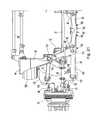
- FIGS. 1-3A steering unit assembly 20 in accordance with the present invention is shown in FIGS. 1-3 .
- Steering unit assembly 20includes a transversely extending relay rod 22 .
- the transversely spaced opposite ends of relay rod 22are operably coupled to tie rods 24 with ball joints 26 .
- Ball joints 26allow for 360 degrees of rotation about horizontal axes 28 that extend substantially parallel with the longitudinal axis or centerline 30 of the vehicle in which steering unit assembly 20 is mounted.
- Steering unit assembly 20includes two steering gears 32 which provide a power assist to the steering wheel of the vehicle.
- Steering gears 32have a hydraulically driven output shaft that is driven in response to a rotational input from the steering wheel of the vehicle.
- the illustrated steering gears 32are conventional hydraulically powered steering gears that operate in a manner well-known to those having ordinary skill in the art. While the illustrated steering gears 32 are hydraulically powered, alternative embodiments could alternatively employ electrically powered steering gears or other forms of power assist or torque transfer devices.
- Each of the steering gears 32have an output shaft 34 that is connected with relay rod 22 with a connecting rod 36 .
- output shafts 34define vertical rotational axes 35 .
- Connecting rods 36are secured at one end to output shafts 34 and rotate along with output shafts 34 .
- the opposite ends of connecting rods 36are secured to relay rod 22 with ball joints 38 .
- Connecting rods 36are pivotally coupled with the vehicle chassis via output shafts 34 and steering gears 32 and thereby act as support arms for relay rod 22 .
- Connecting rods 36are also referred to herein as Pitman arms and/or Pitman rods because rods 36 are secured to a rotating shaft at one end and a translating member at their opposite ends.
- the ball joints 38 coupling connecting rods 36 with relay rod 22are positioned transversely between ball joints 26 .
- the movement of output shaft 34is thereby transmitted by connecting rods 36 resulting in the transverse displacement of relay rod 22 .
- Ball joints 38are oriented so that they allow 360 degrees of rotation about substantially parallel vertical axes 40 .
- vertical rotational axes 40 of ball joints 38 and horizontal rotational axes 28 of ball joints 26are thereby oriented at a 90 degree angle relative to each other.
- ball jointstypically define a primary axis about which 360 degrees of rotation is permitted and also allow pivotal movement about other axes although rotational movement about axes other than the primary axis is often limited to less than 360 degrees.
- Steering gears 32are secured to the vehicle chassis 44 and output shafts 34 are rotated in cooperation as steering gears 32 each receive input from the steering wheel (not shown).
- output shafts 34rotate Pitman arms 36
- relay rod 22is moved laterally.
- tie rods 24are also moved laterally.
- Each of the tie rods 24is connected with a steering knuckle 46 by a ball joint 42 .
- Tie rods 24thereby simultaneously rotate steering knuckles 46 about king pin 48 to steer the wheels supported on the steering knuckles 46 .
- ball joints 42are oriented such that they allow for 360 degrees of rotation about the substantially vertical axes 49 of king pins 48 .
- Knuckle axes 49is best seen in FIG. 11 and is positioned at a substantially, but not precisely, vertical orientation. If greater vertical movement of steering knuckles 46 is desired, ball joints 42 can be re-oriented. (Steering knuckles 46 and king pins 48 can be seen in FIGS. 9-14 which illustrate alternative steering unit assemblies.)
- FIGS. 4-6illustrate the installation of steering gears 32 on vehicle chassis 44 .
- Vehicle chassis 44is a front chassis for a large truck.
- Chassis 44has a “cradle” like form which includes a central void for receiving a large engine. Dashed lines 52 ( FIG. 5 ) indicate the central void area within chassis 44 where the engine is located.
- Chassis 44includes side assemblies 54 located on opposite lateral sides of engine 52 .
- Chassis 44includes a tubular cross member 56 that extends between the upper ends of side assemblies 54 .
- Two lower cross member assemblies 58extend between side chassis assemblies 54 below engine 52 .
- Each of the lower cross member assemblies 58include a structural cross member 60 which, in the illustrated embodiment, takes the form of a tubular member having a slight bend.
- Mounting brackets 62are secured to the opposite ends of cross member 60 and are secured with threaded fasteners 64 , e.g., nut and bolt assemblies.
- Cross members 56 , 58are structural and provide
- brackets 62engage side assemblies 54 on surfaces that are inwardly slanted in a generally V-shaped configuration. This orientation of the mounting surfaces allows cross member assembly 58 to be supported on side chassis assemblies 54 when fasteners 64 are removed.
- cross member assemblies 58allows the cross member assemblies 58 to be more easily attached and detached from chassis 44 .
- threaded fasteners 64can be removed and cross member assemblies 58 will remain in place supported on chassis 44 . This is useful both when removing the assemblies 58 and also when re-attaching the assemblies 58 .
- a side mounting bracket 66 and a lower mounting bracket 68are used when securing steering gears 32 to side chassis assemblies 54 .
- Mounting brackets 66 , 68are secured using threaded fasteners 70 or other suitable means.
- Lower mounting bracket 68includes an opening 72 through which the output shaft 34 of steering gear 32 extends.
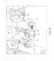
- FIG. 7illustrates the front chassis 44 with steering unit assembly 20 mounted thereon along with the steering knuckles 46 and wheel hub assemblies 74 .
- Wheel hub assemblies 74are rotatably mounted on spindles 76 (see FIGS. 9-14 ) which extend outwardly from steering knuckles 46 .
- the steering knuckles 46 and wheel hub assemblies 74are supported on knuckle carriers 126 that are moveable in a vertical direction.
- Two separate pairs of pivotal upper and lower control arms 78 , 80( FIGS. 15-17 ) maintain spindles 76 in generally horizontal orientation as steering knuckles 46 independently move in a vertical direction in response to irregularities in the road surface.
- the steering unit assembly 20 A illustrated in FIGS. 9-11is generally similar to steering unit 20 .
- steering unit 20 Aincludes only a single steering gear 32 .
- a connecting rod 36connects the output shaft 34 of steering gear 32 to relay rod 21 .
- an idler arm 82is pivotally mounted on chassis 44 with pivot joint 84 .
- Ball joints 37secure connecting rod 36 and idler arm 82 to relay rod 21 .
- Ball joints 27secure the outer ends of relay rod 21 to tie rods 24 .
- Relay rod 21differs from relay rod 22 and has a simplified structure.
- each of the four ball joints 37 , 27 associated with relay rod 21lie in a line 51 .
- each of the four ball joints 27 , 37provide for 360 degree rotation about vertical axes 29 , 39 .
- the steering unit assembly 20 B illustrated in FIGS. 12-14is generally similar to steering unit 20 A. Like steering unit 20 A, steering unit 20 B uses a single steering gear 32 and an idler arm 82 . Steering unit 20 B differs from Steering unit 20 A only in how steering gear 32 is connected with relay rod 21 . Instead of directly connecting steering gear 32 with relay rod 21 via a single connecting rod 36 , a linkage assembly 86 is disposed between the steering gear 32 and relay rod 21 . Linkage assembly 86 includes a lever arm 88 connected to the output shaft 34 of steering gear 32 at connection 90 . An intermediate rod 92 is pivotally connected to lever arm 88 at pivot joint 94 . Another pivot joint 96 connects intermediate rod 92 to an L-shaped bell crank 98 .
- Bell crank 98is mounted on chassis 44 at opening 100 and pivots about a pivot joint mounted within opening 100 . Bell crank 98 is also secured to relay rod 21 via a ball joint 37 .
- intermediate rod 92will pivot bell crank 98 about opening 100 and thereby move relay rod 21 due to the ball joint 37 which connects bell crank 98 with relay rod 21 .
- the independent suspension system 102includes two separate independent suspension assemblies 104 for mounting a paired set of wheels on the vehicle.
- the two wheels (not shown) mounted on the illustrated suspension assemblies 104are the front steerable wheels of the vehicle and are located on opposite sides of the longitudinal centerline 30 of the vehicle.
- the illustrated independent suspension system 102is adapted to be mounted on a truck or other vehicle chassis which includes a pair of side chassis assemblies 54 but may also be used with vehicles having alternative chassis configurations.
- the illustrated embodimentemploys independent suspension assemblies 104 with the front, steerable wheels of the vehicle, similar independent suspension assemblies could also be employed with rear steerable or non-steerable wheels of the vehicle.
- the front wheels of the vehicleare supported on steering knuckles 46 .
- Spindles 76 located on knuckles 46supports wheel hub assemblies 74 which, in turn, support a pair of transversely spaced wheels in a customary manner.
- Wheel hub assemblies 74have a conventional construction and include a brake drum, brake actuator and lug nuts for mounting the wheel.
- King pins 48rotatably mount steering knuckles 46 on knuckle carriers 126 as best understood with reference to FIGS. 21 and 22 .
- knuckle carriers 126are secured to chassis 44 with upper and lower control arms 78 , 80 .
- the upper and lower control arms 78 , 80form a parallelogram structure with chassis 40 and each of the knuckle carriers 126 .
- knuckle carriers 126move vertically relative to chassis 44 while maintaining a substantially constant orientation relative to the chassis 44 and ground surface.
- king pin 48 mounted thereonis maintained at a substantially constant orientation relative to the ground surface.
- steering knuckle 46is rotatably mounted on the king pin 48 and thereby the carrier 126 , steering knuckle 46 and the steerable wheel mounted thereon are also vertically moveable relative to chassis 44 .
- King pin 48allows steering knuckle 46 to rotate relative to knuckle carrier 126 to thereby allow for steering movement of the wheel mounted on steering knuckle 46 as the steering knuckles 46 are selectively rotated about king pins 48 by tie rods 24 .
- the knuckle carriers 126are pivotally attached at their upper ends to an upper control arm 78 with pivot joints 106 .
- the illustrated upper control arms 78are H-shaped with a cross member 78 a joining the two limbs 78 b of upper control arm 78 .
- Pivot joints 106are secured to distal ends 105 of limbs 78 b of upper control arm 78 .
- Pivot joints 106allow the knuckle carriers 126 to rotate about a longitudinally extending axis 107 .
- the upper control arms 78are pivotally attached, opposite knuckle carriers 126 , to side chassis assemblies 54 .
- Bushings 108 and bolts 110pivotally secure upper control arms 46 to chassis 44 and define a longitudinally extending axis 112 about which upper control arms 78 pivot relative to chassis 44 .
- Axes 107 and 112are parallel with each other and substantially parallel with longitudinal axis 30 .
- Relative pivotal movement between upper control arm 78 and steering knuckle 46 about longitudinally extending axis 107 at pivot joint 106 and between upper control arm 78 and chassis 44 about longitudinally extending axis 112allows knuckle carrier 126 to move vertically up and down.
- the knuckle carriers 126are pivotally attached at their lower ends to lower control arms 80 with pivot joints 114 .
- the illustrated lower control arms 80are H-shaped with a cross member 80 a joining the two limbs 80 b of lower control arm 80 .
- Pivot joints 114are secured to distal ends 116 of limbs 80 b of lower control arm 80 .
- Pivot joints 114allow the knuckle carriers 126 to pivot about a longitudinally extending axis 118 .
- the lower control arms 80are pivotally attached, opposite knuckle carriers 126 , to side chassis assemblies 54 .
- Bushings 120 and bolts 122pivotally secure lower control arms 80 to chassis 44 and define a longitudinally extending axis 124 about which lower control arms 80 pivot relative to chassis 44 .
- Relative pivotal movement between lower control arm 80 and knuckle carrier 126 about longitudinally extending axis 118 at pivot joints 114 and between lower control arm 80 and chassis 44 about longitudinally extending axis 124allow knuckle carriers 126 to move vertically up and down.
- Axes 118 and 124are parallel with each other and axes 107 and 112 and control arms 78 , 80 thereby form a parallelogram structure. In the illustrated embodiment, all four of these axes are substantially parallel with longitudinally extending vehicle centerline 30 .
- the parallelogram structure formed by upper and lower control arms 78 , 80maintain knuckle carriers 126 in an upright orientation.
- steering knuckles 46are vertically displaceable relative to the vehicle chassis 44 by the pivotal movement of upper and lower control arms 78 , 80 and vertical movement of knuckle carrier 126 on which steering knuckles 46 are mounted.
- Steering knuckles 46are pivotal about king pins 48 to provide for steering rotation of the wheels mounted on spindles 76 .
- Ball joints 26 , 42 on the opposite ends of tie rods 24allow for the relative vertical movement of steering knuckles 46 and relay rod 20 and the pivotal movement of steering knuckles 46 about king pins 48 .
- the suspension systemincludes air springs 128 , leaf spring assembly 130 and shock absorbers 134 .
- Vertical loads from the steerable wheels mounted on spindles 76are transferred to steering knuckles 46 and then to knuckle carriers 126 in a customary manner. Loads are then transferred to chassis 44 and dampened by air springs 128 , leaf spring assembly 130 and shock absorbers 134 .
- air springs 128the lower end of air springs 128 are secured to mounting brackets 132 while the upper end of air springs 128 are secured to side chassis assemblies 54 .
- Mounting brackets 132are secured to the upper end of knuckle carriers 126 and, thus, air springs 128 transfer vertical forces between knuckle carriers 126 and chassis 44 as can be readily understood with reference to FIGS. 18 , 21 and 22 .
- the illustrated embodimentutilizes conventional air springs 128 .
- Conventional telescoping shock absorbers 134are also employed in the illustrated suspension system to transfer loads between knuckle carriers 126 and chassis 44 . As best understood with reference to FIGS. 21-24 , a conventional shock absorber 134 is secured to each of the knuckle carriers 126 and to the chassis 44 with pivotal joints 136 .
- Leaf spring assembly 130is shown in an exploded view in FIG. 18 and extends between the two knuckle carriers 126 .
- the illustrated leaf spring assembly 130includes an upper leaf spring member 138 and a lower leaf spring member 140 .
- Opposing ends 139 of leaf springs 138 , 140are vertically displaceable relative to the transverse midpoint of leaf spring assembly 130 which is fixed relative to chassis 44 .
- Bushings 142are secured to the opposite ends 139 of lower leaf spring member 140 and pivot bolts 143 pivotally secure leaf spring member 140 to shackle 144 .
- Shackle 144is, in turn, pivotally mounted with a pivot bolt 148 to a shackle bracket 146 secured on knuckle carrier 126 .
- the opposite ends 139 of leaf springs 138 , 140are pivotally secured to a shackle 144 which is itself pivotally secured to knuckle carrier 126 .
- Pivot bolts 143 and 148define pivot axes 145 and 147 respectively. As can be seen in FIG. 19 , axes 145 and 147 are parallel with each other and spaced apart. Axes 145 and 147 are also substantially parallel with longitudinal centerline 30 .
- each of the knuckle carriers 126are pivotally coupled with upper and lower control arms 78 , 80 and shackle members 144 which are each, in turn, pivotally coupled with chassis 44 .
- shackles 144are pivotally coupled to leaf spring assembly 130 which, in turn, is fixed to chassis 44 .
- upper control arms 78are secured to knuckle carriers 126 on the upper regions of knuckle carriers 126 while the lower control arms 80 as well as shackles 44 are secured to knuckle carriers 126 on the lower regions of knuckle carriers 126 .
- the upper control arm 78 and its pivot axes 107 , 112 for each knuckle carrier 126is disposed at a higher vertical position than both lower control arm 80 and its pivot axes 118 , 124 as well as shackles 144 and its pivot axes 147 , 145 .
- shackle members 144merely couple knuckle carriers 126 with leaf spring assembly 130 to thereby dampen the vertical movement of knuckle carriers 126 . It is envisioned, however, that lower control arms 80 could be omitted for some applications and that the pivotal connections between the knuckle carriers 126 and the upper control arm 78 and shackle 44 would be sufficient to maintain the knuckle carriers 126 in a substantially upright orientation.
- a generally H-shaped metal plate 150( FIG. 25 ) is secured to the bottom of side chassis assemblies 54 with the central web 152 of plate 150 extending laterally between the two opposing side chassis assemblies 54 .
- Central web 152forms a downwardly opening channel 154 through which leaf spring members 138 , 140 extend.
- Leaf spring members 138 , 140are secured to chassis 44 at their transverse midpoint within channel 154 proximate the vehicle centerline 30 as best seen in FIGS. 20 , 24 and 25 .
- Engagement plates 156 , 158are located on the top and bottom of leaf spring members 138 , 140 at the midpoint of the leaf spring assembly and secure leaf springs 138 , 140 therebetween. As can be seen in FIG.
- a spacer plate 160is positioned between upper engagement plate 156 and metal plate 150 at the midpoint of leaf springs 138 , 140 .
- Spacer member 160positions leaf springs 138 , 140 at a distance from metal plate 150 and allows leaf springs 138 , 140 to flex within channel 154 .
- Fasteners 162which take the form of a threaded nut and bolt assembly in the illustrated embodiment, extend through metal plate 150 and engagement plates 156 , 158 and tightly secure leaf springs 138 , 140 together and to chassis 44 at the midpoint of leaf springs 138 , 140 .
- a cover plate 164( FIG. 18 ) is attached to the bottom side of metal plate 150 and provides some protection to leaf springs 138 , 140 from road debris. Cover plate 164 is spaced away from leaf springs 138 , 140 near the midpoint of leaf springs 138 , 140 and includes cutouts 166 at its opposite lateral ends to permit the free flexing of leaf springs 138 , 140 . Cover plate 164 also includes access openings 167 to provide access to fasteners 162 .
- Channel member 154 formed by bottom plate 150includes outwardly extending flanges 153 disposed on opposite sides of the channel member 154 . Cover plate 164 is attached to flanges 153 with fasteners 168 . Cover plate 164 is not shown in FIGS. 21 , 22 , 24 and 25 so that leaf spring assembly 130 may be more clearly depicted.
Landscapes
- Engineering & Computer Science (AREA)
- Mechanical Engineering (AREA)
- Chemical & Material Sciences (AREA)
- Combustion & Propulsion (AREA)
- Transportation (AREA)
- Vehicle Body Suspensions (AREA)
Abstract
Description
Claims (29)
Priority Applications (1)
| Application Number | Priority Date | Filing Date | Title |
|---|---|---|---|
| US12/799,469US8485543B2 (en) | 2009-04-29 | 2010-04-26 | Independent suspension and steering assembly |
Applications Claiming Priority (2)
| Application Number | Priority Date | Filing Date | Title |
|---|---|---|---|
| US21483409P | 2009-04-29 | 2009-04-29 | |
| US12/799,469US8485543B2 (en) | 2009-04-29 | 2010-04-26 | Independent suspension and steering assembly |
Publications (2)
| Publication Number | Publication Date |
|---|---|
| US20100276901A1 US20100276901A1 (en) | 2010-11-04 |
| US8485543B2true US8485543B2 (en) | 2013-07-16 |
Family
ID=43029806
Family Applications (1)
| Application Number | Title | Priority Date | Filing Date |
|---|---|---|---|
| US12/799,469Active2031-02-02US8485543B2 (en) | 2009-04-29 | 2010-04-26 | Independent suspension and steering assembly |
Country Status (1)
| Country | Link |
|---|---|
| US (1) | US8485543B2 (en) |
Cited By (18)
| Publication number | Priority date | Publication date | Assignee | Title |
|---|---|---|---|---|
| US20130241167A1 (en)* | 2012-03-14 | 2013-09-19 | Fiat Group Automobiles S.P.A. | Motor-vehicle suspension system with transverse control arms and central leaf spring connecting the arms |
| US9475357B1 (en)* | 2015-04-13 | 2016-10-25 | Reyco Granning, Llc | Strut and air spring IFS assembly maximizing available steering knuckle wheel cut |
| US10093356B2 (en) | 2017-02-21 | 2018-10-09 | Arvinmeritor Technology, Llc | Suspension system |
| US20180312026A1 (en)* | 2017-04-27 | 2018-11-01 | Benteler Automobiltechnik Gmbh | Check rail with a pivot bearing |
| US20180370314A1 (en)* | 2017-06-23 | 2018-12-27 | Dr. Ing. H.C. F. Porsche Aktiengesellschaft | Transverse leaf spring arrangement of a chassis axle of a motor vehicle |
| CN111252139A (en)* | 2020-01-18 | 2020-06-09 | 浙江农林大学 | Improved electronic differential control device for four-wheel drive four-wheel steering of electric vehicles |
| WO2021050605A1 (en)* | 2019-09-09 | 2021-03-18 | Canoo Inc. | Suspension system |
| US11161402B2 (en) | 2019-05-20 | 2021-11-02 | Canoo Technologies Inc. | Electric vehicle platform |
| US11225117B2 (en)* | 2017-12-08 | 2022-01-18 | Isuzu Motors Limited | Suspension device |
| US11251494B2 (en) | 2019-09-20 | 2022-02-15 | Canoo Technologies Inc. | Electric vehicle battery enclosure |
| US11318995B2 (en) | 2019-07-02 | 2022-05-03 | Canoo Technologies Inc. | Impact features |
| US11370263B2 (en)* | 2019-10-25 | 2022-06-28 | Caterpillar Inc. | Space frame front upper body support and frame connection |
| US20220212512A1 (en)* | 2019-06-25 | 2022-07-07 | Nhk Spring Co., Ltd. | Suspension device |
| US11607977B2 (en) | 2019-09-20 | 2023-03-21 | Canoo Technologies Inc. | Vehicle seating systems |
| US20230166573A1 (en)* | 2021-12-01 | 2023-06-01 | Hyundai Motor Company | Vehicle suspension spring device and vehicle suspension system having the same |
| US11731691B2 (en) | 2019-09-11 | 2023-08-22 | Super ATV, LLC | Rear end steering and mounting system |
| US11742540B2 (en) | 2019-01-07 | 2023-08-29 | Canoo Technologies Inc. | Methods and systems for battery pack thermal management |
| US12420869B2 (en) | 2019-07-02 | 2025-09-23 | Canoo Technologies Inc. | Method to reduced lateral deflection of longitudinal members in side impact |
Families Citing this family (27)
| Publication number | Priority date | Publication date | Assignee | Title |
|---|---|---|---|---|
| US9102205B2 (en)* | 2011-02-01 | 2015-08-11 | Polaris Industries Inc. | All terrain vehicle |
| USD666949S1 (en)* | 2011-04-28 | 2012-09-11 | Heidts Acquisition, Llc | Independent rear suspension kit |
| CN102501897B (en)* | 2011-10-29 | 2014-04-02 | 郑州宇通客车股份有限公司 | Follow-up steering mechanism and independent suspension support bridge using same |
| US9828024B2 (en) | 2013-02-06 | 2017-11-28 | Steering Solutions Ip Holding Corporation | Power steering system |
| EP2765060B1 (en)* | 2013-02-06 | 2018-04-11 | Steering Solutions IP Holding Corporation | Vehicle electric power steering contorl system |
| CN103738136B (en)* | 2014-01-27 | 2017-02-15 | 徐州重型机械有限公司 | Independent suspension system and crane with same |
| USD784881S1 (en)* | 2015-11-04 | 2017-04-25 | Steeda Autosports, Inc. | Bushing kit for aligning an independent rear suspension sub-frame to a vehicle body |
| CN108473038A (en) | 2015-12-17 | 2018-08-31 | 艾科泰国际知识产权控股有限公司 | Axle components for vehicles |
| US10981609B2 (en) | 2015-12-30 | 2021-04-20 | Nikola Corporation | Systems, methods, and devices for an automobile door or window |
| US10207751B2 (en)* | 2016-05-09 | 2019-02-19 | Nikola Motor Company Llc | Motor gearbox assembly |
| US11001129B2 (en) | 2015-12-30 | 2021-05-11 | Nikola Corporation | Cargo door for semi-truck |
| WO2017193130A1 (en) | 2016-05-06 | 2017-11-09 | Axletech International Ip Holdings, Llc | Axle assembly with electric motor |
| US10266025B2 (en) | 2016-05-06 | 2019-04-23 | Arvinmeritor Technology, Llc | Suspension module having an air spring pedestal |
| US10435075B2 (en)* | 2016-05-06 | 2019-10-08 | Arvinmeritor Technology, Llc | Suspension module having a subframe assembly |
| USD821930S1 (en)* | 2016-06-06 | 2018-07-03 | Axletech International Ip Holdings, Llc | Gearbox assembly for an axle |
| DE102017112049A1 (en)* | 2017-06-01 | 2018-12-06 | Dr. Ing. H.C. F. Porsche Aktiengesellschaft | Subframe for a rear axle of a motor vehicle |
| JP7161846B2 (en)* | 2017-11-21 | 2022-10-27 | ナブテスコ株式会社 | steering gear |
| EP3572304B1 (en)* | 2018-05-25 | 2021-08-18 | BOMAG GmbH | Construction machine, especially paver |
| US11034204B2 (en)* | 2018-09-25 | 2021-06-15 | Auto Ip Llc | Vehicle suspension |
| USD927578S1 (en) | 2018-09-27 | 2021-08-10 | Allison Transmission, Inc. | Axle assembly |
| US10926596B2 (en)* | 2019-02-28 | 2021-02-23 | Arvinmeritor Technology, Llc | Suspension system |
| US10913321B2 (en) | 2019-03-04 | 2021-02-09 | Arvinmeritor Technology, Llc | Suspension system |
| US10814917B2 (en)* | 2019-03-04 | 2020-10-27 | Arvinmeritor Technology, Llc | Assembly having a skid plate module |
| CN109849606A (en)* | 2019-03-14 | 2019-06-07 | 扬州东升汽车零部件股份有限公司 | The front suspension assembly of commercial vehicle |
| US20230052313A1 (en)* | 2021-08-13 | 2023-02-16 | China Automotive Systems, Inc. | Electric steering assemblies for commercial vehicles |
| CN216184315U (en)* | 2021-09-29 | 2022-04-05 | 宁德时代新能源科技股份有限公司 | Suspension structure, vehicle |
| US20240083211A1 (en)* | 2022-09-08 | 2024-03-14 | Foretravel, Inc. | Heavy duty vehicle suspension with user controlled pneumatic assist |
Citations (36)
| Publication number | Priority date | Publication date | Assignee | Title |
|---|---|---|---|---|
| US1976409A (en)* | 1934-05-12 | 1934-10-09 | William H Nutt | Vehicle wheel suspension |
| US2069420A (en) | 1934-01-02 | 1937-02-02 | Packard Motor Car Co | Motor vehicle |
| US3257123A (en)* | 1964-06-02 | 1966-06-21 | Cambria Spring Co | Spring suspension system for a vehicle |
| US3913941A (en)* | 1974-07-08 | 1975-10-21 | Ford Motor Co | Independent rear suspension for motor vehicles |
| US4288096A (en)* | 1978-10-13 | 1981-09-08 | Honda Giken Kogyo Kabushiki Kaisha | Front wheel suspension mechanism for vehicle |
| US4313618A (en)* | 1980-01-28 | 1982-02-02 | Robinson Russell S | Resilient suspension means for light vehicles |
| US4422666A (en)* | 1981-08-05 | 1983-12-27 | Spring Technology, Ltd. | Suspension mechanism for automotive vehicles |
| US4458918A (en)* | 1981-12-24 | 1984-07-10 | Ford Motor Company | Rear wheel suspension with a transverse leaf spring |
| US4546997A (en)* | 1983-07-28 | 1985-10-15 | John Shuttleworth | Vehicle steering and suspension system |
| US4779894A (en)* | 1985-09-07 | 1988-10-25 | Gkn Technology Limited | Vehicle suspension |
| US4813704A (en)* | 1988-06-20 | 1989-03-21 | Chrysler Motors Corporation | Dual strut wheel suspension |
| US4854606A (en) | 1986-06-16 | 1989-08-08 | Bertin & Cie | Vehicle suspension assembly |
| US4867474A (en) | 1987-11-23 | 1989-09-19 | General Motors Corporation | Adaptive vehicle suspension system |
| US4887841A (en)* | 1986-04-23 | 1989-12-19 | Gkn Technology Limited | Vehicle suspension |
| US4903984A (en) | 1984-03-15 | 1990-02-27 | Honda Giken Kogyo Kabushiki Kaisha | Suspension device |
| US4997202A (en) | 1988-04-15 | 1991-03-05 | Honda Giken Kogyo Kabushiki Kaisha | Suspension system |
| US5058918A (en) | 1989-03-08 | 1991-10-22 | Honda Giken Kogyo Kabushiki Kaisha | Suspension system for motor vehicle |
| US5141209A (en)* | 1987-12-01 | 1992-08-25 | Honda Giken Kogyo Kabushiki Kaisha | Transverse leaf spring type suspension |
| US5251930A (en)* | 1991-01-17 | 1993-10-12 | Honda Giken Kogyo Kabushiki Kaisha | Suspension system with transverse leaf spring |
| US5833026A (en)* | 1994-06-28 | 1998-11-10 | Ab Volvo | Wheel suspension for a pair of driven vehicle wheels |
| US20010042967A1 (en)* | 2000-05-18 | 2001-11-22 | Lars Stenvall | Wheel suspension for a vehicle |
| US20020043780A1 (en)* | 1999-04-26 | 2002-04-18 | Anders Sandahl | Vehicle wheel suspension arrangement |
| US6390486B1 (en) | 1999-09-03 | 2002-05-21 | Ford Global Technologies, Inc. | Wheel suspension for motor vehicles with a wheel-guiding leaf spring |
| US6457729B2 (en)* | 2000-05-18 | 2002-10-01 | Volvo Personvagnar Ab | Wheel suspension for a vehicle |
| US20030234506A1 (en)* | 2002-05-30 | 2003-12-25 | Kenji Yokoyama | Suspension |
| US20040051262A1 (en) | 2002-09-12 | 2004-03-18 | Young Melvin R. | Sled apparatus |
| US6832773B2 (en)* | 2002-05-30 | 2004-12-21 | Mitsubishi Fuso Truck And Bus Corporation | Suspension |
| US20050023792A1 (en) | 2003-08-01 | 2005-02-03 | Miller Steven R. | Lateral leaf spring with inboard air spring trailer suspension |
| US20070075513A1 (en)* | 2005-10-04 | 2007-04-05 | Les Fontes Pns Ltee | Suspension reinforcing kit for a small all terrain vehicle |
| US20070131474A1 (en)* | 2005-12-12 | 2007-06-14 | Ford Global Technologies, Llc | Vehicle wheel suspension assembly |
| US20080252033A1 (en)* | 2007-04-10 | 2008-10-16 | Platner David K | Composite spring with resilient attachment interface |
| US7516968B2 (en)* | 2005-04-29 | 2009-04-14 | Hendrickson Usa, L.L.C. | Wishbone-shaped linkage component and suspension systems incorporating the same |
| US20090218780A1 (en)* | 2006-03-01 | 2009-09-03 | Daimler Ag | Independent suspension for a double-wishbone high link axle |
| US20100123296A1 (en)* | 2008-11-17 | 2010-05-20 | Eric Mark Chelgren | Wheelchair suspension system |
| US20110079978A1 (en)* | 2009-10-01 | 2011-04-07 | Oshkosh Corporation | Axle assembly |
| US7971890B2 (en)* | 2007-07-16 | 2011-07-05 | Reyco Granning, Llc | Independent suspension assembly |
- 2010
- 2010-04-26USUS12/799,469patent/US8485543B2/enactiveActive
Patent Citations (38)
| Publication number | Priority date | Publication date | Assignee | Title |
|---|---|---|---|---|
| US2069420A (en) | 1934-01-02 | 1937-02-02 | Packard Motor Car Co | Motor vehicle |
| US1976409A (en)* | 1934-05-12 | 1934-10-09 | William H Nutt | Vehicle wheel suspension |
| US3257123A (en)* | 1964-06-02 | 1966-06-21 | Cambria Spring Co | Spring suspension system for a vehicle |
| US3913941A (en)* | 1974-07-08 | 1975-10-21 | Ford Motor Co | Independent rear suspension for motor vehicles |
| US4288096A (en)* | 1978-10-13 | 1981-09-08 | Honda Giken Kogyo Kabushiki Kaisha | Front wheel suspension mechanism for vehicle |
| US4313618A (en)* | 1980-01-28 | 1982-02-02 | Robinson Russell S | Resilient suspension means for light vehicles |
| US4422666A (en)* | 1981-08-05 | 1983-12-27 | Spring Technology, Ltd. | Suspension mechanism for automotive vehicles |
| US4458918A (en)* | 1981-12-24 | 1984-07-10 | Ford Motor Company | Rear wheel suspension with a transverse leaf spring |
| US4546997A (en)* | 1983-07-28 | 1985-10-15 | John Shuttleworth | Vehicle steering and suspension system |
| US4903984A (en) | 1984-03-15 | 1990-02-27 | Honda Giken Kogyo Kabushiki Kaisha | Suspension device |
| US4779894A (en)* | 1985-09-07 | 1988-10-25 | Gkn Technology Limited | Vehicle suspension |
| US4887841A (en)* | 1986-04-23 | 1989-12-19 | Gkn Technology Limited | Vehicle suspension |
| US4854606A (en) | 1986-06-16 | 1989-08-08 | Bertin & Cie | Vehicle suspension assembly |
| US4867474A (en) | 1987-11-23 | 1989-09-19 | General Motors Corporation | Adaptive vehicle suspension system |
| US5141209A (en)* | 1987-12-01 | 1992-08-25 | Honda Giken Kogyo Kabushiki Kaisha | Transverse leaf spring type suspension |
| US4997202A (en) | 1988-04-15 | 1991-03-05 | Honda Giken Kogyo Kabushiki Kaisha | Suspension system |
| US4813704A (en)* | 1988-06-20 | 1989-03-21 | Chrysler Motors Corporation | Dual strut wheel suspension |
| US5058918A (en) | 1989-03-08 | 1991-10-22 | Honda Giken Kogyo Kabushiki Kaisha | Suspension system for motor vehicle |
| US5251930A (en)* | 1991-01-17 | 1993-10-12 | Honda Giken Kogyo Kabushiki Kaisha | Suspension system with transverse leaf spring |
| US5833026A (en)* | 1994-06-28 | 1998-11-10 | Ab Volvo | Wheel suspension for a pair of driven vehicle wheels |
| US20020043780A1 (en)* | 1999-04-26 | 2002-04-18 | Anders Sandahl | Vehicle wheel suspension arrangement |
| US6588779B2 (en)* | 1999-04-26 | 2003-07-08 | Volvo Car Corporation | Vehicle wheel suspension arrangement |
| US6390486B1 (en) | 1999-09-03 | 2002-05-21 | Ford Global Technologies, Inc. | Wheel suspension for motor vehicles with a wheel-guiding leaf spring |
| US20010042967A1 (en)* | 2000-05-18 | 2001-11-22 | Lars Stenvall | Wheel suspension for a vehicle |
| US6457729B2 (en)* | 2000-05-18 | 2002-10-01 | Volvo Personvagnar Ab | Wheel suspension for a vehicle |
| US6832773B2 (en)* | 2002-05-30 | 2004-12-21 | Mitsubishi Fuso Truck And Bus Corporation | Suspension |
| US20030234506A1 (en)* | 2002-05-30 | 2003-12-25 | Kenji Yokoyama | Suspension |
| US6863290B2 (en)* | 2002-05-30 | 2005-03-08 | Mitsubishi Fuso Truck And Bus Corporation | Suspension |
| US20040051262A1 (en) | 2002-09-12 | 2004-03-18 | Young Melvin R. | Sled apparatus |
| US20050023792A1 (en) | 2003-08-01 | 2005-02-03 | Miller Steven R. | Lateral leaf spring with inboard air spring trailer suspension |
| US7516968B2 (en)* | 2005-04-29 | 2009-04-14 | Hendrickson Usa, L.L.C. | Wishbone-shaped linkage component and suspension systems incorporating the same |
| US20070075513A1 (en)* | 2005-10-04 | 2007-04-05 | Les Fontes Pns Ltee | Suspension reinforcing kit for a small all terrain vehicle |
| US20070131474A1 (en)* | 2005-12-12 | 2007-06-14 | Ford Global Technologies, Llc | Vehicle wheel suspension assembly |
| US20090218780A1 (en)* | 2006-03-01 | 2009-09-03 | Daimler Ag | Independent suspension for a double-wishbone high link axle |
| US20080252033A1 (en)* | 2007-04-10 | 2008-10-16 | Platner David K | Composite spring with resilient attachment interface |
| US7971890B2 (en)* | 2007-07-16 | 2011-07-05 | Reyco Granning, Llc | Independent suspension assembly |
| US20100123296A1 (en)* | 2008-11-17 | 2010-05-20 | Eric Mark Chelgren | Wheelchair suspension system |
| US20110079978A1 (en)* | 2009-10-01 | 2011-04-07 | Oshkosh Corporation | Axle assembly |
Cited By (28)
| Publication number | Priority date | Publication date | Assignee | Title |
|---|---|---|---|---|
| US8777248B2 (en)* | 2012-03-14 | 2014-07-15 | Fiat Group Automobiles S.P.A. | Motor-vehicle suspension system with transverse control arms and central leaf spring connecting the arms |
| US20130241167A1 (en)* | 2012-03-14 | 2013-09-19 | Fiat Group Automobiles S.P.A. | Motor-vehicle suspension system with transverse control arms and central leaf spring connecting the arms |
| US9475357B1 (en)* | 2015-04-13 | 2016-10-25 | Reyco Granning, Llc | Strut and air spring IFS assembly maximizing available steering knuckle wheel cut |
| US10093356B2 (en) | 2017-02-21 | 2018-10-09 | Arvinmeritor Technology, Llc | Suspension system |
| US10974558B2 (en)* | 2017-04-27 | 2021-04-13 | Benteler Automobiltechnik Gmbh | Check rail with a pivot bearing |
| US20180312026A1 (en)* | 2017-04-27 | 2018-11-01 | Benteler Automobiltechnik Gmbh | Check rail with a pivot bearing |
| US20180370314A1 (en)* | 2017-06-23 | 2018-12-27 | Dr. Ing. H.C. F. Porsche Aktiengesellschaft | Transverse leaf spring arrangement of a chassis axle of a motor vehicle |
| US11225117B2 (en)* | 2017-12-08 | 2022-01-18 | Isuzu Motors Limited | Suspension device |
| US11742540B2 (en) | 2019-01-07 | 2023-08-29 | Canoo Technologies Inc. | Methods and systems for battery pack thermal management |
| US11161402B2 (en) | 2019-05-20 | 2021-11-02 | Canoo Technologies Inc. | Electric vehicle platform |
| US11292326B2 (en) | 2019-05-20 | 2022-04-05 | Canoo Technologies Inc. | Electric vehicle platform |
| US11833895B2 (en) | 2019-05-20 | 2023-12-05 | Canoo Technologies Inc. | Electric vehicle platform |
| US12103375B2 (en) | 2019-05-20 | 2024-10-01 | Canoo Technologies Inc. | Electric vehicle platform |
| US20220212512A1 (en)* | 2019-06-25 | 2022-07-07 | Nhk Spring Co., Ltd. | Suspension device |
| US11820185B2 (en)* | 2019-06-25 | 2023-11-21 | Nhk Spring Co., Ltd. | Suspension device |
| US12168475B2 (en) | 2019-07-02 | 2024-12-17 | Canoo Technologies Inc. | Impact features |
| US11318995B2 (en) | 2019-07-02 | 2022-05-03 | Canoo Technologies Inc. | Impact features |
| US12420869B2 (en) | 2019-07-02 | 2025-09-23 | Canoo Technologies Inc. | Method to reduced lateral deflection of longitudinal members in side impact |
| US11618292B2 (en) | 2019-09-09 | 2023-04-04 | Canoo Technologies Inc. | Suspension system |
| WO2021050605A1 (en)* | 2019-09-09 | 2021-03-18 | Canoo Inc. | Suspension system |
| US11731691B2 (en) | 2019-09-11 | 2023-08-22 | Super ATV, LLC | Rear end steering and mounting system |
| US11738670B2 (en) | 2019-09-20 | 2023-08-29 | Canoo Technologies Inc. | Vehicle seating systems |
| US11607977B2 (en) | 2019-09-20 | 2023-03-21 | Canoo Technologies Inc. | Vehicle seating systems |
| US11251494B2 (en) | 2019-09-20 | 2022-02-15 | Canoo Technologies Inc. | Electric vehicle battery enclosure |
| US11370263B2 (en)* | 2019-10-25 | 2022-06-28 | Caterpillar Inc. | Space frame front upper body support and frame connection |
| CN111252139A (en)* | 2020-01-18 | 2020-06-09 | 浙江农林大学 | Improved electronic differential control device for four-wheel drive four-wheel steering of electric vehicles |
| US20230166573A1 (en)* | 2021-12-01 | 2023-06-01 | Hyundai Motor Company | Vehicle suspension spring device and vehicle suspension system having the same |
| US11890906B2 (en)* | 2021-12-01 | 2024-02-06 | Hyundai Motor Company | Vehicle suspension spring device and vehicle suspension system having the same |
Also Published As
| Publication number | Publication date |
|---|---|
| US20100276901A1 (en) | 2010-11-04 |
Similar Documents
| Publication | Publication Date | Title |
|---|---|---|
| US8485543B2 (en) | Independent suspension and steering assembly | |
| US7971890B2 (en) | Independent suspension assembly | |
| RU2550784C2 (en) | Suspension system for heavy and professional vehicles | |
| US4705294A (en) | Air suspension assembly with universal pivoted hanger bearings and rigid mount angular torque spring-beam | |
| EP0287278B1 (en) | A vehicle chassis transverse structural member | |
| US9242672B2 (en) | Utility vehicle | |
| CA2389140C (en) | Suspension structure | |
| US20100276904A1 (en) | High travel independent suspension with upright | |
| US6866277B2 (en) | Front suspension | |
| US11964531B2 (en) | Transverse wheel suspension system | |
| US20070013160A1 (en) | Steer axle suspension | |
| MXPA04006583A (en) | Control rod suspension with outboard shock. | |
| US7188850B2 (en) | Beam axle suspension with diagonal link | |
| JPH06510721A (en) | Axle structure for commercial vehicles | |
| CN119894693A (en) | Chassis axle structure with axle for commercial vehicle | |
| CN119907747A (en) | Axle structure for a utility vehicle chassis including an axle bridge | |
| US4344642A (en) | Vehicle axle mounting arrangement | |
| AU2014328481B2 (en) | Conversion of a two-wheel drive vehicle to a four-wheel drive vehicle | |
| WO2018015942A1 (en) | Vehicle wheel knuckle configuration | |
| RU2509657C2 (en) | Suspension of transport facility | |
| RU2567133C9 (en) | Independent suspension of rear wheels | |
| RU2567133C2 (en) | Independent suspension of rear wheels | |
| JP3189708B2 (en) | Vehicle suspension | |
| JP2025528586A (en) | Axle structure for a utility vehicle chassis with an axle bridge | |
| GB2184073A (en) | Suspension units for trailers |
Legal Events
| Date | Code | Title | Description |
|---|---|---|---|
| AS | Assignment | Owner name:TUTHILL CORPORATION, ILLINOIS Free format text:ASSIGNMENT OF ASSIGNORS INTEREST;ASSIGNORS:RICHARDSON, GREGORY A.;HINZ, JOHN A.;CONAWAY, RICHARD LEE;REEL/FRAME:024377/0385 Effective date:20100421 | |
| AS | Assignment | Owner name:TUTHILL CORPORATION, ILLINOIS Free format text:PARTIAL RELEASE BY SECURED PARTY;ASSIGNOR:BANK OF AMERICA, N.A.;REEL/FRAME:025663/0035 Effective date:20110107 | |
| AS | Assignment | Owner name:REYCO GRANNING, LLC, MISSOURI Free format text:ASSIGNMENT OF ASSIGNORS INTEREST;ASSIGNOR:TUTHILL CORPORATION;REEL/FRAME:026420/0610 Effective date:20110518 | |
| STCF | Information on status: patent grant | Free format text:PATENTED CASE | |
| FEPP | Fee payment procedure | Free format text:PAT HOLDER NO LONGER CLAIMS SMALL ENTITY STATUS, ENTITY STATUS SET TO UNDISCOUNTED (ORIGINAL EVENT CODE: STOL); ENTITY STATUS OF PATENT OWNER: LARGE ENTITY | |
| FPAY | Fee payment | Year of fee payment:4 | |
| MAFP | Maintenance fee payment | Free format text:PAYMENT OF MAINTENANCE FEE, 8TH YEAR, LARGE ENTITY (ORIGINAL EVENT CODE: M1552); ENTITY STATUS OF PATENT OWNER: LARGE ENTITY Year of fee payment:8 | |
| MAFP | Maintenance fee payment | Free format text:PAYMENT OF MAINTENANCE FEE, 12TH YEAR, LARGE ENTITY (ORIGINAL EVENT CODE: M1553); ENTITY STATUS OF PATENT OWNER: LARGE ENTITY Year of fee payment:12 | |
| AS | Assignment | Owner name:HENDRICKSON MT. VERNON, LLC, ILLINOIS Free format text:ASSIGNMENT OF ASSIGNORS INTEREST;ASSIGNOR:REYCO GRANNING LLC;REEL/FRAME:070981/0392 Effective date:20240531 |