US8480749B2 - Friction fit and vertebral endplate-preserving spinal implant - Google Patents
Friction fit and vertebral endplate-preserving spinal implantDownload PDFInfo
- Publication number
- US8480749B2 US8480749B2US13/462,904US201213462904AUS8480749B2US 8480749 B2US8480749 B2US 8480749B2US 201213462904 AUS201213462904 AUS 201213462904AUS 8480749 B2US8480749 B2US 8480749B2
- Authority
- US
- United States
- Prior art keywords
- implant
- spinal implant
- bone
- anterior
- posterior
- Prior art date
- Legal status (The legal status is an assumption and is not a legal conclusion. Google has not performed a legal analysis and makes no representation as to the accuracy of the status listed.)
- Expired - Lifetime
Links
Images


Classifications
- A—HUMAN NECESSITIES
- A61—MEDICAL OR VETERINARY SCIENCE; HYGIENE
- A61F—FILTERS IMPLANTABLE INTO BLOOD VESSELS; PROSTHESES; DEVICES PROVIDING PATENCY TO, OR PREVENTING COLLAPSING OF, TUBULAR STRUCTURES OF THE BODY, e.g. STENTS; ORTHOPAEDIC, NURSING OR CONTRACEPTIVE DEVICES; FOMENTATION; TREATMENT OR PROTECTION OF EYES OR EARS; BANDAGES, DRESSINGS OR ABSORBENT PADS; FIRST-AID KITS
- A61F2/00—Filters implantable into blood vessels; Prostheses, i.e. artificial substitutes or replacements for parts of the body; Appliances for connecting them with the body; Devices providing patency to, or preventing collapsing of, tubular structures of the body, e.g. stents
- A61F2/02—Prostheses implantable into the body
- A61F2/30—Joints
- A61F2/44—Joints for the spine, e.g. vertebrae, spinal discs
- A61F2/4455—Joints for the spine, e.g. vertebrae, spinal discs for the fusion of spinal bodies, e.g. intervertebral fusion of adjacent spinal bodies, e.g. fusion cages
- A61F2/4465—Joints for the spine, e.g. vertebrae, spinal discs for the fusion of spinal bodies, e.g. intervertebral fusion of adjacent spinal bodies, e.g. fusion cages having a circular or kidney shaped cross-section substantially perpendicular to the axis of the spine
- A—HUMAN NECESSITIES
- A61—MEDICAL OR VETERINARY SCIENCE; HYGIENE
- A61F—FILTERS IMPLANTABLE INTO BLOOD VESSELS; PROSTHESES; DEVICES PROVIDING PATENCY TO, OR PREVENTING COLLAPSING OF, TUBULAR STRUCTURES OF THE BODY, e.g. STENTS; ORTHOPAEDIC, NURSING OR CONTRACEPTIVE DEVICES; FOMENTATION; TREATMENT OR PROTECTION OF EYES OR EARS; BANDAGES, DRESSINGS OR ABSORBENT PADS; FIRST-AID KITS
- A61F2/00—Filters implantable into blood vessels; Prostheses, i.e. artificial substitutes or replacements for parts of the body; Appliances for connecting them with the body; Devices providing patency to, or preventing collapsing of, tubular structures of the body, e.g. stents
- A61F2/02—Prostheses implantable into the body
- A61F2/30—Joints
- A61F2/3094—Designing or manufacturing processes
- A61F2/30965—Reinforcing the prosthesis by embedding particles or fibres during moulding or dipping
- A—HUMAN NECESSITIES
- A61—MEDICAL OR VETERINARY SCIENCE; HYGIENE
- A61F—FILTERS IMPLANTABLE INTO BLOOD VESSELS; PROSTHESES; DEVICES PROVIDING PATENCY TO, OR PREVENTING COLLAPSING OF, TUBULAR STRUCTURES OF THE BODY, e.g. STENTS; ORTHOPAEDIC, NURSING OR CONTRACEPTIVE DEVICES; FOMENTATION; TREATMENT OR PROTECTION OF EYES OR EARS; BANDAGES, DRESSINGS OR ABSORBENT PADS; FIRST-AID KITS
- A61F2/00—Filters implantable into blood vessels; Prostheses, i.e. artificial substitutes or replacements for parts of the body; Appliances for connecting them with the body; Devices providing patency to, or preventing collapsing of, tubular structures of the body, e.g. stents
- A61F2/02—Prostheses implantable into the body
- A61F2/30—Joints
- A61F2/46—Special tools for implanting artificial joints
- A61F2/4684—Trial or dummy prostheses
- A—HUMAN NECESSITIES
- A61—MEDICAL OR VETERINARY SCIENCE; HYGIENE
- A61F—FILTERS IMPLANTABLE INTO BLOOD VESSELS; PROSTHESES; DEVICES PROVIDING PATENCY TO, OR PREVENTING COLLAPSING OF, TUBULAR STRUCTURES OF THE BODY, e.g. STENTS; ORTHOPAEDIC, NURSING OR CONTRACEPTIVE DEVICES; FOMENTATION; TREATMENT OR PROTECTION OF EYES OR EARS; BANDAGES, DRESSINGS OR ABSORBENT PADS; FIRST-AID KITS
- A61F2/00—Filters implantable into blood vessels; Prostheses, i.e. artificial substitutes or replacements for parts of the body; Appliances for connecting them with the body; Devices providing patency to, or preventing collapsing of, tubular structures of the body, e.g. stents
- A61F2/02—Prostheses implantable into the body
- A61F2/28—Bones
- A61F2002/2817—Bone stimulation by chemical reactions or by osteogenic or biological products for enhancing ossification, e.g. by bone morphogenetic or morphogenic proteins [BMP] or by transforming growth factors [TGF]
- A—HUMAN NECESSITIES
- A61—MEDICAL OR VETERINARY SCIENCE; HYGIENE
- A61F—FILTERS IMPLANTABLE INTO BLOOD VESSELS; PROSTHESES; DEVICES PROVIDING PATENCY TO, OR PREVENTING COLLAPSING OF, TUBULAR STRUCTURES OF THE BODY, e.g. STENTS; ORTHOPAEDIC, NURSING OR CONTRACEPTIVE DEVICES; FOMENTATION; TREATMENT OR PROTECTION OF EYES OR EARS; BANDAGES, DRESSINGS OR ABSORBENT PADS; FIRST-AID KITS
- A61F2/00—Filters implantable into blood vessels; Prostheses, i.e. artificial substitutes or replacements for parts of the body; Appliances for connecting them with the body; Devices providing patency to, or preventing collapsing of, tubular structures of the body, e.g. stents
- A61F2/02—Prostheses implantable into the body
- A61F2/28—Bones
- A61F2002/2835—Bone graft implants for filling a bony defect or an endoprosthesis cavity, e.g. by synthetic material or biological material
- A—HUMAN NECESSITIES
- A61—MEDICAL OR VETERINARY SCIENCE; HYGIENE
- A61F—FILTERS IMPLANTABLE INTO BLOOD VESSELS; PROSTHESES; DEVICES PROVIDING PATENCY TO, OR PREVENTING COLLAPSING OF, TUBULAR STRUCTURES OF THE BODY, e.g. STENTS; ORTHOPAEDIC, NURSING OR CONTRACEPTIVE DEVICES; FOMENTATION; TREATMENT OR PROTECTION OF EYES OR EARS; BANDAGES, DRESSINGS OR ABSORBENT PADS; FIRST-AID KITS
- A61F2/00—Filters implantable into blood vessels; Prostheses, i.e. artificial substitutes or replacements for parts of the body; Appliances for connecting them with the body; Devices providing patency to, or preventing collapsing of, tubular structures of the body, e.g. stents
- A61F2/02—Prostheses implantable into the body
- A61F2/30—Joints
- A61F2002/30001—Additional features of subject-matter classified in A61F2/28, A61F2/30 and subgroups thereof
- A61F2002/30003—Material related properties of the prosthesis or of a coating on the prosthesis
- A61F2002/30004—Material related properties of the prosthesis or of a coating on the prosthesis the prosthesis being made from materials having different values of a given property at different locations within the same prosthesis
- A61F2002/30014—Material related properties of the prosthesis or of a coating on the prosthesis the prosthesis being made from materials having different values of a given property at different locations within the same prosthesis differing in elasticity, stiffness or compressibility
- A—HUMAN NECESSITIES
- A61—MEDICAL OR VETERINARY SCIENCE; HYGIENE
- A61F—FILTERS IMPLANTABLE INTO BLOOD VESSELS; PROSTHESES; DEVICES PROVIDING PATENCY TO, OR PREVENTING COLLAPSING OF, TUBULAR STRUCTURES OF THE BODY, e.g. STENTS; ORTHOPAEDIC, NURSING OR CONTRACEPTIVE DEVICES; FOMENTATION; TREATMENT OR PROTECTION OF EYES OR EARS; BANDAGES, DRESSINGS OR ABSORBENT PADS; FIRST-AID KITS
- A61F2/00—Filters implantable into blood vessels; Prostheses, i.e. artificial substitutes or replacements for parts of the body; Appliances for connecting them with the body; Devices providing patency to, or preventing collapsing of, tubular structures of the body, e.g. stents
- A61F2/02—Prostheses implantable into the body
- A61F2/30—Joints
- A61F2002/30001—Additional features of subject-matter classified in A61F2/28, A61F2/30 and subgroups thereof
- A61F2002/30108—Shapes
- A61F2002/3011—Cross-sections or two-dimensional shapes
- A61F2002/30112—Rounded shapes, e.g. with rounded corners
- A61F2002/30133—Rounded shapes, e.g. with rounded corners kidney-shaped or bean-shaped
- A—HUMAN NECESSITIES
- A61—MEDICAL OR VETERINARY SCIENCE; HYGIENE
- A61F—FILTERS IMPLANTABLE INTO BLOOD VESSELS; PROSTHESES; DEVICES PROVIDING PATENCY TO, OR PREVENTING COLLAPSING OF, TUBULAR STRUCTURES OF THE BODY, e.g. STENTS; ORTHOPAEDIC, NURSING OR CONTRACEPTIVE DEVICES; FOMENTATION; TREATMENT OR PROTECTION OF EYES OR EARS; BANDAGES, DRESSINGS OR ABSORBENT PADS; FIRST-AID KITS
- A61F2/00—Filters implantable into blood vessels; Prostheses, i.e. artificial substitutes or replacements for parts of the body; Appliances for connecting them with the body; Devices providing patency to, or preventing collapsing of, tubular structures of the body, e.g. stents
- A61F2/02—Prostheses implantable into the body
- A61F2/30—Joints
- A61F2002/30001—Additional features of subject-matter classified in A61F2/28, A61F2/30 and subgroups thereof
- A61F2002/30316—The prosthesis having different structural features at different locations within the same prosthesis; Connections between prosthetic parts; Special structural features of bone or joint prostheses not otherwise provided for
- A61F2002/30329—Connections or couplings between prosthetic parts, e.g. between modular parts; Connecting elements
- A61F2002/30405—Connections or couplings between prosthetic parts, e.g. between modular parts; Connecting elements made by screwing complementary threads machined on the parts themselves
- A—HUMAN NECESSITIES
- A61—MEDICAL OR VETERINARY SCIENCE; HYGIENE
- A61F—FILTERS IMPLANTABLE INTO BLOOD VESSELS; PROSTHESES; DEVICES PROVIDING PATENCY TO, OR PREVENTING COLLAPSING OF, TUBULAR STRUCTURES OF THE BODY, e.g. STENTS; ORTHOPAEDIC, NURSING OR CONTRACEPTIVE DEVICES; FOMENTATION; TREATMENT OR PROTECTION OF EYES OR EARS; BANDAGES, DRESSINGS OR ABSORBENT PADS; FIRST-AID KITS
- A61F2/00—Filters implantable into blood vessels; Prostheses, i.e. artificial substitutes or replacements for parts of the body; Appliances for connecting them with the body; Devices providing patency to, or preventing collapsing of, tubular structures of the body, e.g. stents
- A61F2/02—Prostheses implantable into the body
- A61F2/30—Joints
- A61F2002/30001—Additional features of subject-matter classified in A61F2/28, A61F2/30 and subgroups thereof
- A61F2002/30316—The prosthesis having different structural features at different locations within the same prosthesis; Connections between prosthetic parts; Special structural features of bone or joint prostheses not otherwise provided for
- A61F2002/30535—Special structural features of bone or joint prostheses not otherwise provided for
- A61F2002/30593—Special structural features of bone or joint prostheses not otherwise provided for hollow
- A—HUMAN NECESSITIES
- A61—MEDICAL OR VETERINARY SCIENCE; HYGIENE
- A61F—FILTERS IMPLANTABLE INTO BLOOD VESSELS; PROSTHESES; DEVICES PROVIDING PATENCY TO, OR PREVENTING COLLAPSING OF, TUBULAR STRUCTURES OF THE BODY, e.g. STENTS; ORTHOPAEDIC, NURSING OR CONTRACEPTIVE DEVICES; FOMENTATION; TREATMENT OR PROTECTION OF EYES OR EARS; BANDAGES, DRESSINGS OR ABSORBENT PADS; FIRST-AID KITS
- A61F2/00—Filters implantable into blood vessels; Prostheses, i.e. artificial substitutes or replacements for parts of the body; Appliances for connecting them with the body; Devices providing patency to, or preventing collapsing of, tubular structures of the body, e.g. stents
- A61F2/02—Prostheses implantable into the body
- A61F2/30—Joints
- A61F2002/30001—Additional features of subject-matter classified in A61F2/28, A61F2/30 and subgroups thereof
- A61F2002/30316—The prosthesis having different structural features at different locations within the same prosthesis; Connections between prosthetic parts; Special structural features of bone or joint prostheses not otherwise provided for
- A61F2002/30535—Special structural features of bone or joint prostheses not otherwise provided for
- A61F2002/30604—Special structural features of bone or joint prostheses not otherwise provided for modular
- A—HUMAN NECESSITIES
- A61—MEDICAL OR VETERINARY SCIENCE; HYGIENE
- A61F—FILTERS IMPLANTABLE INTO BLOOD VESSELS; PROSTHESES; DEVICES PROVIDING PATENCY TO, OR PREVENTING COLLAPSING OF, TUBULAR STRUCTURES OF THE BODY, e.g. STENTS; ORTHOPAEDIC, NURSING OR CONTRACEPTIVE DEVICES; FOMENTATION; TREATMENT OR PROTECTION OF EYES OR EARS; BANDAGES, DRESSINGS OR ABSORBENT PADS; FIRST-AID KITS
- A61F2/00—Filters implantable into blood vessels; Prostheses, i.e. artificial substitutes or replacements for parts of the body; Appliances for connecting them with the body; Devices providing patency to, or preventing collapsing of, tubular structures of the body, e.g. stents
- A61F2/02—Prostheses implantable into the body
- A61F2/30—Joints
- A61F2/30767—Special external or bone-contacting surface, e.g. coating for improving bone ingrowth
- A61F2/30771—Special external or bone-contacting surface, e.g. coating for improving bone ingrowth applied in original prostheses, e.g. holes or grooves
- A61F2002/30772—Apertures or holes, e.g. of circular cross section
- A61F2002/30784—Plurality of holes
- A61F2002/30785—Plurality of holes parallel
- A—HUMAN NECESSITIES
- A61—MEDICAL OR VETERINARY SCIENCE; HYGIENE
- A61F—FILTERS IMPLANTABLE INTO BLOOD VESSELS; PROSTHESES; DEVICES PROVIDING PATENCY TO, OR PREVENTING COLLAPSING OF, TUBULAR STRUCTURES OF THE BODY, e.g. STENTS; ORTHOPAEDIC, NURSING OR CONTRACEPTIVE DEVICES; FOMENTATION; TREATMENT OR PROTECTION OF EYES OR EARS; BANDAGES, DRESSINGS OR ABSORBENT PADS; FIRST-AID KITS
- A61F2/00—Filters implantable into blood vessels; Prostheses, i.e. artificial substitutes or replacements for parts of the body; Appliances for connecting them with the body; Devices providing patency to, or preventing collapsing of, tubular structures of the body, e.g. stents
- A61F2/02—Prostheses implantable into the body
- A61F2/30—Joints
- A61F2/30767—Special external or bone-contacting surface, e.g. coating for improving bone ingrowth
- A61F2/30771—Special external or bone-contacting surface, e.g. coating for improving bone ingrowth applied in original prostheses, e.g. holes or grooves
- A61F2002/30836—Special external or bone-contacting surface, e.g. coating for improving bone ingrowth applied in original prostheses, e.g. holes or grooves knurled
- A—HUMAN NECESSITIES
- A61—MEDICAL OR VETERINARY SCIENCE; HYGIENE
- A61F—FILTERS IMPLANTABLE INTO BLOOD VESSELS; PROSTHESES; DEVICES PROVIDING PATENCY TO, OR PREVENTING COLLAPSING OF, TUBULAR STRUCTURES OF THE BODY, e.g. STENTS; ORTHOPAEDIC, NURSING OR CONTRACEPTIVE DEVICES; FOMENTATION; TREATMENT OR PROTECTION OF EYES OR EARS; BANDAGES, DRESSINGS OR ABSORBENT PADS; FIRST-AID KITS
- A61F2/00—Filters implantable into blood vessels; Prostheses, i.e. artificial substitutes or replacements for parts of the body; Appliances for connecting them with the body; Devices providing patency to, or preventing collapsing of, tubular structures of the body, e.g. stents
- A61F2/02—Prostheses implantable into the body
- A61F2/30—Joints
- A61F2/30767—Special external or bone-contacting surface, e.g. coating for improving bone ingrowth
- A61F2/30771—Special external or bone-contacting surface, e.g. coating for improving bone ingrowth applied in original prostheses, e.g. holes or grooves
- A61F2002/30878—Special external or bone-contacting surface, e.g. coating for improving bone ingrowth applied in original prostheses, e.g. holes or grooves with non-sharp protrusions, for instance contacting the bone for anchoring, e.g. keels, pegs, pins, posts, shanks, stems, struts
- A61F2002/30891—Plurality of protrusions
- A61F2002/30892—Plurality of protrusions parallel
- A—HUMAN NECESSITIES
- A61—MEDICAL OR VETERINARY SCIENCE; HYGIENE
- A61F—FILTERS IMPLANTABLE INTO BLOOD VESSELS; PROSTHESES; DEVICES PROVIDING PATENCY TO, OR PREVENTING COLLAPSING OF, TUBULAR STRUCTURES OF THE BODY, e.g. STENTS; ORTHOPAEDIC, NURSING OR CONTRACEPTIVE DEVICES; FOMENTATION; TREATMENT OR PROTECTION OF EYES OR EARS; BANDAGES, DRESSINGS OR ABSORBENT PADS; FIRST-AID KITS
- A61F2/00—Filters implantable into blood vessels; Prostheses, i.e. artificial substitutes or replacements for parts of the body; Appliances for connecting them with the body; Devices providing patency to, or preventing collapsing of, tubular structures of the body, e.g. stents
- A61F2/02—Prostheses implantable into the body
- A61F2/30—Joints
- A61F2/30767—Special external or bone-contacting surface, e.g. coating for improving bone ingrowth
- A61F2002/30906—Special external or bone-contacting surface, e.g. coating for improving bone ingrowth shot- sand- or grit-blasted
- A—HUMAN NECESSITIES
- A61—MEDICAL OR VETERINARY SCIENCE; HYGIENE
- A61F—FILTERS IMPLANTABLE INTO BLOOD VESSELS; PROSTHESES; DEVICES PROVIDING PATENCY TO, OR PREVENTING COLLAPSING OF, TUBULAR STRUCTURES OF THE BODY, e.g. STENTS; ORTHOPAEDIC, NURSING OR CONTRACEPTIVE DEVICES; FOMENTATION; TREATMENT OR PROTECTION OF EYES OR EARS; BANDAGES, DRESSINGS OR ABSORBENT PADS; FIRST-AID KITS
- A61F2/00—Filters implantable into blood vessels; Prostheses, i.e. artificial substitutes or replacements for parts of the body; Appliances for connecting them with the body; Devices providing patency to, or preventing collapsing of, tubular structures of the body, e.g. stents
- A61F2/02—Prostheses implantable into the body
- A61F2/30—Joints
- A61F2/30767—Special external or bone-contacting surface, e.g. coating for improving bone ingrowth
- A61F2002/30925—Special external or bone-contacting surface, e.g. coating for improving bone ingrowth etched
- A—HUMAN NECESSITIES
- A61—MEDICAL OR VETERINARY SCIENCE; HYGIENE
- A61F—FILTERS IMPLANTABLE INTO BLOOD VESSELS; PROSTHESES; DEVICES PROVIDING PATENCY TO, OR PREVENTING COLLAPSING OF, TUBULAR STRUCTURES OF THE BODY, e.g. STENTS; ORTHOPAEDIC, NURSING OR CONTRACEPTIVE DEVICES; FOMENTATION; TREATMENT OR PROTECTION OF EYES OR EARS; BANDAGES, DRESSINGS OR ABSORBENT PADS; FIRST-AID KITS
- A61F2/00—Filters implantable into blood vessels; Prostheses, i.e. artificial substitutes or replacements for parts of the body; Appliances for connecting them with the body; Devices providing patency to, or preventing collapsing of, tubular structures of the body, e.g. stents
- A61F2/02—Prostheses implantable into the body
- A61F2/30—Joints
- A61F2/44—Joints for the spine, e.g. vertebrae, spinal discs
- A61F2002/448—Joints for the spine, e.g. vertebrae, spinal discs comprising multiple adjacent spinal implants within the same intervertebral space or within the same vertebra, e.g. comprising two adjacent spinal implants
- A—HUMAN NECESSITIES
- A61—MEDICAL OR VETERINARY SCIENCE; HYGIENE
- A61F—FILTERS IMPLANTABLE INTO BLOOD VESSELS; PROSTHESES; DEVICES PROVIDING PATENCY TO, OR PREVENTING COLLAPSING OF, TUBULAR STRUCTURES OF THE BODY, e.g. STENTS; ORTHOPAEDIC, NURSING OR CONTRACEPTIVE DEVICES; FOMENTATION; TREATMENT OR PROTECTION OF EYES OR EARS; BANDAGES, DRESSINGS OR ABSORBENT PADS; FIRST-AID KITS
- A61F2/00—Filters implantable into blood vessels; Prostheses, i.e. artificial substitutes or replacements for parts of the body; Appliances for connecting them with the body; Devices providing patency to, or preventing collapsing of, tubular structures of the body, e.g. stents
- A61F2/02—Prostheses implantable into the body
- A61F2/30—Joints
- A61F2/46—Special tools for implanting artificial joints
- A61F2/4603—Special tools for implanting artificial joints for insertion or extraction of endoprosthetic joints or of accessories thereof
- A61F2002/4629—Special tools for implanting artificial joints for insertion or extraction of endoprosthetic joints or of accessories thereof connected to the endoprosthesis or implant via a threaded connection
- A—HUMAN NECESSITIES
- A61—MEDICAL OR VETERINARY SCIENCE; HYGIENE
- A61F—FILTERS IMPLANTABLE INTO BLOOD VESSELS; PROSTHESES; DEVICES PROVIDING PATENCY TO, OR PREVENTING COLLAPSING OF, TUBULAR STRUCTURES OF THE BODY, e.g. STENTS; ORTHOPAEDIC, NURSING OR CONTRACEPTIVE DEVICES; FOMENTATION; TREATMENT OR PROTECTION OF EYES OR EARS; BANDAGES, DRESSINGS OR ABSORBENT PADS; FIRST-AID KITS
- A61F2220/00—Fixations or connections for prostheses classified in groups A61F2/00 - A61F2/26 or A61F2/82 or A61F9/00 or A61F11/00 or subgroups thereof
- A61F2220/0025—Connections or couplings between prosthetic parts, e.g. between modular parts; Connecting elements
- A—HUMAN NECESSITIES
- A61—MEDICAL OR VETERINARY SCIENCE; HYGIENE
- A61F—FILTERS IMPLANTABLE INTO BLOOD VESSELS; PROSTHESES; DEVICES PROVIDING PATENCY TO, OR PREVENTING COLLAPSING OF, TUBULAR STRUCTURES OF THE BODY, e.g. STENTS; ORTHOPAEDIC, NURSING OR CONTRACEPTIVE DEVICES; FOMENTATION; TREATMENT OR PROTECTION OF EYES OR EARS; BANDAGES, DRESSINGS OR ABSORBENT PADS; FIRST-AID KITS
- A61F2310/00—Prostheses classified in A61F2/28 or A61F2/30 - A61F2/44 being constructed from or coated with a particular material
- A61F2310/00005—The prosthesis being constructed from a particular material
- A61F2310/00011—Metals or alloys
- A61F2310/00017—Iron- or Fe-based alloys, e.g. stainless steel
- A—HUMAN NECESSITIES
- A61—MEDICAL OR VETERINARY SCIENCE; HYGIENE
- A61F—FILTERS IMPLANTABLE INTO BLOOD VESSELS; PROSTHESES; DEVICES PROVIDING PATENCY TO, OR PREVENTING COLLAPSING OF, TUBULAR STRUCTURES OF THE BODY, e.g. STENTS; ORTHOPAEDIC, NURSING OR CONTRACEPTIVE DEVICES; FOMENTATION; TREATMENT OR PROTECTION OF EYES OR EARS; BANDAGES, DRESSINGS OR ABSORBENT PADS; FIRST-AID KITS
- A61F2310/00—Prostheses classified in A61F2/28 or A61F2/30 - A61F2/44 being constructed from or coated with a particular material
- A61F2310/00005—The prosthesis being constructed from a particular material
- A61F2310/00011—Metals or alloys
- A61F2310/00023—Titanium or titanium-based alloys, e.g. Ti-Ni alloys
Definitions
- the inventionrelates generally to interbody spinal implants and methods of using such implants and, more particularly, to an implant having one or more openings of predetermined sizes and shapes to achieve design trade offs depending upon a particular application.
- the spineis a column made of vertebrae and discs.
- the vertebraeprovide the support and structure of the spine while the spinal discs, located between the vertebrae, act as cushions or “shock absorbers.” These discs also contribute to the flexibility and motion of the spinal column. Over time, the discs may become diseased or infected, may develop deformities such as tears or cracks, or may simply lose structural integrity (e.g., the discs may bulge or flatten). Impaired discs can affect the anatomical functions of the vertebrae, due to the resultant lack of proper biomechanical support, and are often associated with chronic back pain.
- Spinal fusionhas become a recognized surgical procedure for mitigating back pain by restoring biomechanical and anatomical integrity to the spine.
- Spinal fusion techniquesinvolve the removal, or partial removal, of at least one intervertebral disc and preparation of the disc space for receiving an implant by shaping the exposed vertebral endplates. An implant is then inserted between the opposing endplates.
- Spinal fusion procedurescan be achieved using a posterior or an anterior approach.
- Anterior interbody fusion proceduresgenerally have the advantages of reduced operative times and reduced blood loss. Further, anterior procedures do not interfere with the posterior anatomic structure of the lumbar spine. Anterior procedures also minimize scarring within the spinal canal while still achieving improved fusion rates, which is advantageous from a structural and biomechanical perspective. These generally preferred anterior procedures are particularly advantageous in providing improved access to the disc space, and thus correspondingly better endplate preparation.
- interbody implant systemshave been introduced to facilitate interbody fusion.
- Traditional threaded implantsinvolve at least two cylindrical bodies, each typically packed with bone graft material, surgically placed on opposite sides of the mid-sagittal plane through pre-tapped holes within the intervertebral disc space. This location is not the preferable seating position for an implant system, however, because only a relatively small portion of the vertebral endplate is contacted by these cylindrical implants. Accordingly, these implant bodies will likely contact the softer cancellous bone rather than the stronger cortical bone, or apophyseal rim, of the vertebral endplate.
- the seating of these threaded cylindrical implantsmay also compromise biomechanical integrity by reducing the area in which to distribute mechanical forces, thus increasing the apparent stress experienced by both the implant and vertebrae. Still further, a substantial risk of implant subsidence (defined as sinking or settling) into the softer cancellous bone of the vertebral body may arise from such improper seating.
- open ring-shaped cage implant systemsare generally shaped to mimic the anatomical contour of the vertebral body.
- Traditional ring-shaped cagesare generally comprised of allograft bone material, however, harvested from the human femur.
- allograft bone materialrestricts the usable size and shape of the resultant implant.
- many of these femoral ring-shaped cagesgenerally have a medial-lateral width of less than 25 mm. Therefore, these cages may not be of a sufficient size to contact the strong cortical bone, or apophyseal rim, of the vertebral endplate.
- These size-limited implant systemsmay also poorly accommodate related instrumentation such as drivers, reamers, distractors, and the like.
- these implant systemsmay lack sufficient structural integrity to withstand repeated impact and may fracture during implantation.
- other traditional non-allograft ring-shaped cage systemsmay be size-limited due to varied and complex supplemental implant instrumentation which may obstruct the disc space while requiring greater exposure of the operating space.
- These supplemental implant instrumentation systemsalso generally increase the instrument load upon the surgeon.
- the surgical procedure corresponding to an implant systemshould preserve as much vertebral endplate bone surface as possible by minimizing the amount of bone removed.
- This vertebral endplate bone surface, or subchondral boneis generally much stronger than the underlying cancellous bone.
- Preservation of the endplate bone stockensures biomechanical integrity of the endplates and minimizes the risk of implant subsidence.
- proper interbody implant designshould provide for optimal seating of the implant while utilizing the maximum amount of available supporting vertebral bone stock.
- interbody spinal implantsgenerally do not seat properly on the preferred structural bone located near the apophyseal rim of the vertebral body, which is primarily composed of preferred dense subchondral bone. Accordingly, there is a need in the art for interbody spinal implants which better utilize the structurally supportive bone of the apophyseal rim.
- challengescan be identified as inherent in traditional anterior spinal fusion devices.
- Such challengesinclude: (1) end-plate preparation; (2) implant difficulty; (3) materials of construction; (4) implant expulsion; (5) implant subsidence; (6) insufficient room for bone graft; (7) stress shielding; (8) lack of implant incorporation with vertebral bone; (9) limitations on radiographic visualization; and (10) cost of manufacture and inventory.
- the firstis aggressive end-plate removal with box-chisel types of tools to create a nice match of end-plate geometry with implant geometry.
- the end-platesare typically destroyed. Such destruction means that the load-bearing implant is pressed against soft cancellous bone and the implant tends to subside.
- the second traditional end-plate preparation methodpreserves the end-plates by just removing cartilage with curettes.
- the end-platesare concave; hence, if a flat implant is used, the implant is not very stable. Even if a convex implant is used, it is very difficult to match the implant geometry with the end-plate geometry, as the end-plate geometry varies from patient-to-patient and on the extent of disease.
- the third traditional end-plate preparation methoduses threaded fusion cages.
- the cagesare implanted by reaming out corresponding threads in the end-plates. This method also violates the structure.
- Traditional anterior spinal fusion devicescan also be difficult to implant.
- Some traditional implants with teethhave sharp edges. These edges can bind to the surrounding soft tissue during implantation, creating surgical challenges.
- secondary instrumentationis used to keep the disc space distracted during implantation.
- the use of such instrumentationmeans that the exposure needs to be large enough to accommodate the instrumentation. If there is a restriction on the exposure size, then the maximum size of the implant available for use is correspondingly limited.
- the need for secondary instrumentation for distraction during implantationalso adds an additional step or two in surgery.
- secondary instrumentationmay sometimes over-distract the annulus, reducing the ability of the annulus to compress a relatively undersized implant. The compression provided by the annulus on the implant is important to maintain the initial stability of the implant.
- anterior spinal surgerythere are traditionally three trajectories of implants: anterior, antero-lateral, and lateral.
- Each approachhas its advantages and drawbacks. Sometimes the choice of the approach is dictated by surgeon preference, and sometimes it is dictated by patient anatomy and biomechanics.
- a typical traditional implanthas design features to accommodate only one or two of these approaches in a single implant, restricting intra-operative flexibility.
- Typical devicesare made of PEEK or cadaver bone. Materials such as PEEK or cadaver bone do not have the structural strength to withstand impact loads required during implantation and may fracture during implantation.
- PEEKis an abbreviation for polyetherether-ketone, a high-performance engineering thermoplastic with excellent chemical and fatigue resistance plus thermal stability. With a maximum continuous working temperature of 480° F., PEEK offers superior mechanical properties. Superior chemical resistance has allowed PEEK to work effectively as a metal replacement in harsh environments. PEEK grades offer chemical and water resistance similar to PPS (polyphenylene sulfide), but can operate at higher temperatures. PEEK materials are inert to all common solvents and resist a wide range of organic and inorganic liquids. Thus, for hostile environments, PEEK is a high-strength alternative to fluoropolymers.
- cadaver bonehas several drawbacks.
- the shapes and sizes of the implantsare restricted by the bone from which the implant is machined.
- Cadaver bonecarries with it the risk of disease transmission and raises shelf-life and storage issues.
- cadaver bonehas insufficient mechanical strength for clinical application.
- Subsidence of the implantis a complex issue and has been attributed to many factors. Some of these factors include aggressive removal of the end-plate; an implant stiffness significantly greater than the vertebral bone; smaller sized implants which tend to seat in the center of the disc space, against the weakest region of the end-plates; and implants with sharp edges which can cause localized stress fractures in the end-plates at the point of contact.
- the most common solution to the problem of subsidenceis to choose a less stiff implant material. This is why PEEK and cadaver bone have become the most common materials for spinal fusion implants. PEEK is softer than cortical bone, but harder than cancellous bone.
- Cadaver bone implantsare restricted in their size by the bone from which they are machined. Their wall thickness also has to be great to create sufficient structural integrity for their desired clinical application. These design restrictions do not leave much room for filling the bone graft material into cortical bone implants. The exposure-driven limitations on implant size narrow the room left inside the implant geometry for bone grafting even for metal implants. Such room is further reduced in the case of PEEK implants because their wall thickness needs to be greater as compared to metal implants due to structural strength needs.
- the bone graft packed inside the implantneeds to be loaded mechanically.
- the stiffness of the implant materialis much greater than the adjacent vertebral bone and takes up a majority of the mechanical loads, “shielding” the bone graft material from becoming mechanically loaded.
- the most common solutionis to choose a less stiff implant material. Again, this is why PEEK and cadaver bone have become the most common materials for spinal fusion implants. As noted above, although harder than cancellous bone, PEEK is softer than cortical bone.
- the typical fusion implantis not able to incorporate with the vertebral bone, even years after implantation. Such inability persists despite the use of a variety of different materials to construct the implants.
- cadaver boneis resorbable and will be replaced by new bone once it resorbs.
- Hedrocelis a composite material composed of carbon and tantalum, an inert metal, that has been used as a material for spinal fusion implants. Hedrocel is designed to allow bone in-growth into the implant.
- PEEKhas been reported to become surrounded by fibrous tissue which precludes it from incorporating with surrounding bone.
- bio-active materialswhich can incorporate into bone. The application of such bio-active materials has been limited, however, for several reasons, including biocompatibility, structural strength, and lack of regulatory approval.
- PEEKis radiolucent. Traditional implants made of PEEK need to have radiographic markers embedded into the implants so that implant position can be tracked on an X-ray. Cadaver bone has some radiopacity and does not interfere with radiographic assessment as much as metal implants.
- the inventionis directed to interbody spinal implants and to methods of using such implants.
- the implantscan be inserted, using methods of the invention, from a variety of vantages, including anterior, antero-lateral, and lateral implantation.
- the spinal implantis preferably adapted to be inserted into a prepared disc space via a procedure which does not destroy the vertebral end-plates, or contacts the vertebral end-plates only peripherally, allowing the intact vertebral end-plates to deflect like a diaphragm under axial compressive loads generated due to physiologic activities and pressurize the bone graft material disposed inside the spinal implant.
- a spinal implantis generally oval-shaped in transverse cross-section, and comprises a top surface, a bottom surface, opposing lateral sides, and opposing anterior and posterior portions.
- the posterior portiondefines a leading end for insertion into a disc space, has a generally rounded nose profile, and has a shorter height than the anterior portion such that the implant comprises a lordotic angle capable of aligning the spine.
- the top surface, the bottom surface, or bothhave a roughened surface topography adapted to grip bone and inhibit migration of the implant.
- the lengths between the top surface and the posterior portion, the bottom surface and the posterior portion, the top surface and the lateral sides, and the bottom surface and the lateral sidesinclude generally rounded or blunt and radiused intersections.
- the junction of the top and/or bottom surface and the anterior portioncomprises an expulsion-resistant edge to resist pullout of the implant from the spine.
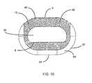
- the spinal implantis preferably substantially hollow and comprises a centrally disposed vertical aperture extending from the top surface to the bottom surface, defining a transverse rim in the top and bottom surfaces having a greater first thickness in the area of the posterior portion than a second thickness in the area of the anterior portion to improve utilization of the vertebrae, and having a maximum width at its center, between the opposing lateral sides, and tapering inwardly from the center to each of its ends, one end proximate the anterior portion and the other end proximate the posterior portion.
- the substantially hollow portionmay contain a bone graft material adapted to facilitate the formation of a solid fusion column within the spine.
- the bone graft materialmay be cancellous autograft bone, allograft bone, demineralized bone matrix (DBM), porous synthetic bone graft substitute, bone morphogenic protein (BMP), or a combination thereof.
- the spinal implantmay be fabricated from a metal.
- a preferred metalis titanium.
- the spinal implantmay be fabricated from a non-metallic material, non-limiting examples of which include polyetherether-ketone, hedrocel, ultra-high molecular weight polyethylene, and combinations thereof.
- the spinal implantmay be fabricated from both a metal and a non-metallic material, including a composite thereof.
- a compositemay be formed, in part, of titanium and, in part, of polyetherether-ketone, hedrocel, ultra-high molecular weight polyethylene, or combinations thereof.
- the anterior portionmay be substantially flat and adapted to receive impact from an implant tool.
- the anterior portionmay comprise an opening for achieving one or more of the following functions: being adapted to engage a delivery device, facilitating delivery of bone graft material to the substantially hollow center, enhancing visibility of the implant, and providing access to the bone graft material.
- the inventionalso features systems that include such interbody spinal implants.
- the systemsmay comprise an implant and a distractor.
- the systemsmay further comprise a rasp.
- the systemsmay further comprise an implant holder capable of engaging an opening on the anterior portion of the spinal implant.
- the systemsmay further comprise a bone graft material, non-limiting examples of which include cancellous autograft bone, allograft bone, demineralized bone matrix (DBM), porous synthetic bone graft substitute, bone morphogenic protein (BMP), or a combination thereof.
- BBMdemineralized bone matrix
- BMPbone morphogenic protein
- the distractor of the systemsmay comprise a top surface, a bottom surface, opposing lateral sides, and opposing anterior and posterior portions, with the posterior portion defining a leading end for insertion first into a disc space, having a generally rounded nose profile, and having a shorter height than the anterior portion such that the distractor comprises a lordotic angle.
- the distractoris adapted to be inserted into a prepared disc space via a procedure which does not destroy the vertebral end-plates, or contacts the vertebral end-plates only peripherally.
- the rasp of the systemsmay comprise a top surface, a bottom surface, opposing lateral sides, opposing anterior and posterior portions, and a plurality of teeth having a tip facing the anterior portion.
- the teethpreferably extend laterally across the top surface, the bottom surface, or the top and bottom surfaces of the rasp.
- the posterior portion of the rasppreferably defines a leading end for insertion first into a disc space, has a generally rounded nose profile, and has a shorter height than the anterior portion such that the rasp comprises a lordotic angle.
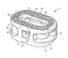
- FIG. 1shows a perspective view of an embodiment of the interbody spinal implant having a generally oval shape and roughened surface topography on the top surface;
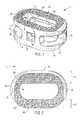
- FIG. 2depicts a top view of the interbody spinal implant
- FIG. 3depicts an anterior view of the interbody spinal implant
- FIG. 4depicts a posterior view of the interbody spinal implant
- FIG. 5Adepicts a first post-operative radiograph showing visualization of an embodiment of the interbody spinal implant
- FIG. 5Bdepicts a second post-operative radiograph showing visualization of an embodiment of the interbody spinal implant
- FIG. 5Cdepicts a third post-operative radiograph showing visualization of an embodiment of the interbody spinal implant
- FIG. 6shows an exemplary surgical tool (implant holder) to be used with certain embodiments of the interbody spinal implant
- FIG. 7shows an exemplary distractor used during certain methods of implantation
- FIG. 8shows an exemplary rasp used during certain methods of implantation
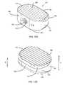
- FIG. 9shows an isometric view of an embodiment of the interbody spinal implant having a generally oval shape, a roughened surface topography, and rounded edges about the proximal surface;
- FIG. 10shows a top view of the embodiment of the interbody spinal implant shown in FIG. 9 , and further shows anti-expulsion edges;
- FIG. 11shows a side view of the embodiment of the interbody spinal implant shown in
- FIG. 9
- FIG. 12Ashows an anterior, isometric view of an embodiment of a rasp instrument to assist in preparation of the bone for accommodation of the interbody spinal implant shown in FIG. 9 ;
- FIG. 12Bshows a posterior, isometric view of an embodiment of a rasp instrument to assist in preparation of the bone for accommodation of the interbody spinal implant shown in FIG. 9 ;
- FIG. 12Cshows a side view of the rasp instrument shown in FIG. 12A and FIG. 12B ;
- FIG. 12Dshows an enlarged view of the rasping teeth of the rasp instrument shown in FIG. 12C ;
- FIG. 12Eshows a front-on view of the anterior portion of the rasp instrument shown in FIG. 12A and FIG. 12B ;
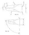
- FIG. 13Ashows a posterior, isometric view of a trial instrument to assist in sizing the implant during surgery
- FIG. 13Bshows an anterior, isometric view of a trial instrument to assist in sizing the implant during surgery
- FIG. 13Cshows a side view of the trial instrument shown in FIG. 13A and FIG. 13B ;
- FIG. 13Dshows a front-on view of the anterior portion of the trial instrument shown in FIG. 13A and FIG. 13B .
- Certain embodiments of the inventionmay be especially suited for placement between adjacent human vertebral bodies.
- the implants of the inventionmay be used in procedures such as Anterior Lumbar Interbody Fusion (ALIF), Posterior Lumbar Interbody Fusion (PLIF), Transforaminal Lumbar Interbody Fusion (TLIF), and cervical fusion. Certain embodiments do not extend beyond the outer dimensions of the vertebral bodies.
- Interbody spinal implantsallow for improved seating over the apophyseal rim of the vertebral body. Still further, interbody spinal implants, as now taught, better utilize this vital surface area over which fusion may occur and may better bear the considerable biomechanical loads presented through the spinal column with minimal interference with other anatomical or neurological spinal structures. Even further, interbody spinal implants, according to certain aspects of the invention, allow for improved visualization of implant seating and fusion assessment. Interbody spinal implants, as now taught, may also facilitate osteointegration with the surrounding living bone.
- Anterior interbody spinal implants in accordance with certain aspects of the inventioncan be preferably made of a durable material such as stainless steel, stainless steel alloy, titanium, or titanium alloy, but can also be made of other durable materials such as, but not limited to, polymeric, ceramic, and composite materials.
- a durable materialsuch as stainless steel, stainless steel alloy, titanium, or titanium alloy
- other durable materialssuch as, but not limited to, polymeric, ceramic, and composite materials.
- certain embodiments of the inventionmay be comprised of a biocompatible, polymeric matrix reinforced with bioactive fillers, fibers, or both.
- Certain embodiments of the inventionmay be comprised of urethane dimethacrylate (DUDMA)/tri-ethylene glycol dimethacrylate (TEDGMA) blended resin and a plurality of fillers and fibers including bioactive fillers and E-glass fibers.
- Durable materialsmay also consist of any number of pure metals, metal alloys, or both.
- Titanium and its alloysare generally preferred for certain embodiments of the invention due to their acceptable, and desirable, strength and biocompatibility.
- certain embodiments of the present interbody spinal implantmay have improved structural integrity and may better resist fracture during implantation by impact. Interbody spinal implants, as now taught, may therefore be used as a distractor during implantation.
- FIG. 1shows a perspective view of a first embodiment of the interbody spinal implant 1 especially well adapted for use in an ALIF procedure.
- FIG. 9shows a perspective view of an alternative embodiment of the interbody spinal implant 1 .
- the interbody spinal implant 1includes a body having a top surface 10 , a bottom surface 20 , opposing lateral sides 30 , and opposing anterior 40 and posterior 50 portions.
- One or both of the top surface 10 and the bottom surface 20has a roughened topography 80 .
- the roughened topography 80is distinct from the teeth provided on the surfaces of some conventional devices.
- the interbody spinal implant 1is substantially hollow and has a generally oval-shaped transverse cross-sectional area with smooth, rounded, or both smooth and rounded lateral sides 30 and posterior-lateral corners 52 .
- a substantially hollow implant 1includes an implant 1 having at least about 33% of the interior volume of the implant 1 vacant.
- the implant 1includes at least one vertical aperture 60 that extends the entire height of the implant body. As illustrated in the top view of FIG. 2 and FIG. 10 , the vertical aperture 60 may further define a transverse rim 100 having a greater posterior portion thickness 55 than an anterior portion thickness 45 .
- the opposing lateral sides 30 and the anterior portion 40have a rim thickness 45 of about 5 mm, while the posterior portion 50 has a rim thickness 55 of about 7 mm.
- the rim posterior portion thickness 55may allow for better stress sharing between the implant 1 and the adjacent vertebral endplates and helps to compensate for the weaker posterior endplate bone.
- the transverse rim 100has a generally large surface area and contacts the vertebral endplate. The transverse rim 100 may act to better distribute contact stresses upon the implant 1 , and hence minimize the risk of subsidence while maximizing contact with the apophyseal supportive bone.
- the transverse rim 100may have a substantially constant thickness (e.g., for the anterior portion thickness 45 to be substantially the same as the posterior portion thickness 55 ) or for the posterior portion 50 to have a rim thickness 55 less than that of the opposing lateral sides 30 and the anterior portion 40 .
- implant fixationmay depend, at least in part, on the attachment and proliferation of osteoblasts and like-functioning cells upon the implant surface. Still further, it appears that these cells attach more readily to relatively rough surfaces rather than smooth surfaces. In this manner, a surface may be bioactive due to its ability to facilitate cellular attachment and osteointegration.
- the surface roughened topography 80may better promote the osteointegration of the implant 1 .
- the surface roughened topography 80may also better grip the vertebral endplate surfaces and inhibit implant migration of the implant 1 upon placement and seating in a patient.
- the implant 1further includes the roughened topography 80 on at least a portion of its top 10 and bottom 20 surfaces for gripping adjacent bone and inhibiting migration of the implant 1 .
- FIG. 1 and FIG. 9show roughened topography 80 on embodiments of the implant 1 .
- the roughened topography 80may be obtained through a variety of techniques including, without limitation, chemical etching, shot peening, plasma etching, laser etching, or abrasive blasting (such as sand or grit blasting).
- the interbody spinal implant 1may be comprised of titanium, or a titanium alloy, having the surface roughened topography 80 .
- the surfaces of the implant 1are preferably bioactive.
- the roughened topography 80is obtained via the repetitive masking and chemical or electrochemical milling processes described in U.S. Pat. Nos. 5,258,098; 5,507,815; 5,922,029; and 6,193,762. Each of these patents is incorporated in this document by reference.
- the surfaceis prepared through an etching process which utilizes the random application of a maskant and subsequent etching of the metallic substrate in areas unprotected by the maskant. This etching process is repeated a number of times as necessitated by the amount and nature of the irregularities required for any particular application.
- Control of the strength of the etchant material, the temperature at which the etching process takes place, and the time allotted for the etching processallow fine control over the resulting surface produced by the process.
- the number of repetitions of the etching processcan also be used to control the surface features.
- an etchant mixture of nitric acid (HNO 3 ) and hydrofluoric (HF) acidmay be repeatedly applied to a titanium surface to produce an average etch depth of about 0.53 mm.
- Interbody spinal implants 1in accordance with some preferred embodiments of the invention, may be comprised of titanium, or a titanium alloy, having an average surface roughness of about 100 ⁇ m. Surface roughness may be measured using a laser profilometer or other standard instrumentation.
- chemical modification of the titanium implant surfacescan be achieved using HF and a combination of hydrochloric acid and sulfuric acid (HCl/H 2 SO 4 ).
- HFhydrochloric acid and sulfuric acid
- the first exposureis to HF and the second is to HCl/H 2 SO 4 .
- Chemical acid etching alone of the titanium implant surfacehas the potential to greatly enhance osteointegration without adding particulate matter (e.g., hydroxyapatite) or embedding surface contaminants (e.g., grit particles).
- the implant 1may be shaped to reduce the risk of subsidence, and improve stability, by maximizing contact with the apophyseal rim of vertebral endplates.
- Embodimentsmay be provided in a variety of anatomical footprints having a medial-lateral width ranging from about 32 mm to about 44 mm.
- An interbody spinal implant 1generally does not require extensive supplemental or obstructive implant instrumentation to maintain the prepared disc space during implantation.
- the interbody spinal implant 1 and associated implantation methodsallow for larger-sized implants as compared with other size-limited interbody spinal implants known in the art. This advantage allows for greater medial-lateral width and correspondingly greater contact with the apophyseal rim.
- FIG. 3depicts an anterior view
- FIG. 4depicts a posterior view, of an embodiment of the interbody spinal implant 1 .
- the implant 1has an opening 90 in the anterior portion 40 .
- the posterior portion 50has a similarly shaped opening 90 .
- the embodiment shown in FIG. 9may also have a posterior portion 50 with a similarly shaped opening 90 (not shown).
- only the anterior portion 40has the opening 90 while the posterior portion 50 has an alternative opening 92 (which may have a size and shape different from the opening 90 ).
- the opening 90has a number of functions. One function is to facilitate manipulation of the implant 1 by the caretaker.
- the caretakermay insert a surgical tool into the opening 90 and, through the engagement between the surgical tool and the opening 90 , manipulate the implant 1 .
- the opening 90may be threaded to enhance the engagement.
- FIG. 6shows an exemplary surgical tool, specifically an implant holder 2 , to be used with certain embodiments of the interbody spinal implant 1 .
- the implant holder 2has a handle 4 that the caretaker can easily grasp and an end 6 that engages the opening 90 .
- the end 6may be threaded to engage corresponding threads in the opening 90 .
- the size and shape of the opening 90can be varied to accommodate a variety of tools.
- the opening 90is substantially square as illustrated in FIGS. 1 , 3 , 4 , and 9 , other sizes and shapes are feasible.
- the implant 1may further include at least one transverse aperture 70 that extends the entire transverse length of the implant body. As shown in FIGS. 5A-5C and in FIG. 9 , the at least one transverse aperture 70 may provide improved visibility of the implant 1 during surgical procedures to ensure proper implant placement and seating, and may also improve post-operative assessment of implant fusion. Still further, the substantially hollow area defined by the implant 1 may be filled with cancellous autograft bone, allograft bone, DBM, porous synthetic bone graft substitute, BMP, or combinations of these materials (collectively, bone graft materials), to facilitate the formation of a solid fusion column within the spine of a patient.
- the anterior portion 40 , or trailing edge, of the implant 1is preferably generally greater in height than the opposing posterior portion 50 .
- the implant 1may comprise a lordotic-angle, e.g., may be wedge-shaped to facilitate sagittal alignment.
- the anterior portion 40 of the implant 1may comprise a height H that is larger than the height H′ of the posterior portion 50 , as shown in FIG. 9 and FIG. 11A .
- the anterior portion 40 height H and posterior portion 50 height H′may vary, and may vary independently, in order to accommodate different lordotic angles in the spines of different patients.
- FIG. 11A and FIG. 11Bthe implant 1 may better compensate for less supportive bone such as that which may be found in the posterior regions of the vertebral endplate.
- the anterior portion 40 height H and the posterior portion 50 height H′may each independently be from about 5 mm to about 75 mm.
- the height H and the height H′may each independently be from about 8 mm to about 20 mm.
- either the height H or the height H′may be selected from about 5 mm, about 8 mm, about 10 mm, about 12 mm, about 14 mm, about 16 mm, about 18 mm, about 20 mm, about 22 mm, about 24 mm, about 25 mm, about 28 mm, about 30 mm, about 33 mm, about 35 mm, about 38 mm, about 40 mm, about 43 mm, about 45 mm, about 48 mm, about 50 mm, about 53 mm, about 55 mm, about 58 mm, about 60 mm, about 63 mm, about 65 mm, about 68 mm, about 70 mm, about 75 mm, or about 80 mm.
- the difference in the anterior portion 40 height H and the posterior portion 50 height H′may result in a lordotic angle L of from about 3 degrees to about 15 degrees, from the horizontal plane of the implant 1 .
- the implant 1comprises an angle of about 4 degrees, about 5 degrees, about 6 degrees, about 7 degrees, about 8 degrees, about 9 degrees, about 10 degrees, about 11 degrees, or about 12 degrees. Angles of lordosis of about 4 degrees, about 6 degrees, about 7 degrees, or about 12 degrees are highly preferred.
- the posterior portion 50 of the interbody implant 1may also be highly radiused, thus allowing for ease of implantation into the disc space.
- the posterior portion 50may have a generally blunt nosed profile, including a generally rounded profile, for example, as shown in FIG. 9 and in FIG. 11A .
- the posterior portion edges 54including the top and bottom edges and lateral corner edges of the posterior portion 50 , are preferably generally rounded, and are preferably smooth.
- the anterior portion 40 of the implant 1is substantially flat.
- the anterior portion 40provides a face that can receive impact from a tool, such as a surgical hammer, to force the implant 1 into position.
- the implant 1has a first expulsion-resistant edge 8 where the anterior portion 40 meets the top surface 10 , where the anterior portion 40 meets the bottom surface 20 , or in both locations; see, e.g., FIG. 1 , FIG. 9 , and FIG. 10 .
- the edge 8may be sharp or sharpened, or may comprise a blade, a lip, a ridge, or a barb.
- the expulsion-resistant edges 8(top and/or bottom) function to resist movement of the implant 1 out from the spine once the implant 1 has been inserted into position.
- the implant 1may also comprise a second expulsion-resistant edge 9 on at least the posterior edge 62 of the vertical aperture 60 , as shown in FIG. 10 .
- the second expulsion-resistant edge 9may be present where the vertical aperture 60 intersects the top surface 10 , where the vertical aperture 60 intersects the bottom surface 20 , or in both locations.
- the edge 9may be sharp or sharpened, or may comprise a blade, a lip, a ridge, or a barb.
- the expulsion-resistant edges 9top and/or bottom function to resist movement of the implant 1 out from the spine once the implant 1 has been inserted into position, and may be used in addition to or in lieu of the expulsion-resistant edge 8 on the anterior portion 40 .
- first expulsion-resistant edge 8 and the second expulsion-resistant edge 9function to resist movement of the implant 1 out from the spine once it the implant 1 has been inserted into position, and their movement resistance may be additive, though their respective contributions to resistance may not be equal.
- the expulsion-resistant edge 8may comprise an anti-expulsion edge angle E, for example, as shown in FIG. 11B .
- the anti-expulsion edge angle Emay be from about 80 degrees to about 100 degrees.
- the anti-expulsion edge angle Emay be measured by taking into account the lordosis angle L of the implant 1 .
- the anti-expulsion edge angle Eis measured by subtracting half of the lordotic angle L from 90. For example, where the lordosis angle L of the implant 1 is 12 degrees, the anti-expulsion edge angle E is 84 degrees (90 ⁇ (12 ⁇ 0.5)).
- the anti-expulsion edge angle Emay be about 80 degrees, about 81 degrees, about 82 degrees, about 83 degrees, about 84 degrees, about 85 degrees, about 86 degrees, about 86.5 degrees, about 87 degrees, about 88 degrees, or about 89 degrees.
- Certain embodiments of the inventionare particularly suited for use during interbody spinal implant procedures (or vertebral body replacement procedures) and may act as a final distractor during implantation, thus minimizing the instrument load upon the surgeon.
- the spinemay first be exposed via an anterior approach and the center of the disc space identified.
- the disc spaceis then initially prepared for implant insertion by removing vertebral cartilage.
- Soft tissue and residual cartilagemay then also be removed from the vertebral endplates.
- Vertebral distractionmay be performed using trials of various-sized embodiments of the interbody spinal implant 1 .
- the determinatively sized interbody implant 1may then be inserted in the prepared disc space for final placement.
- the distraction procedure and final insertionmay also be performed under fluoroscopic guidance.
- the substantially hollow area within the implant bodymay optionally be filled, at least partially, with bone fusion-enabling materials such as, without limitation, cancellous autograft bone, allograft bone, DBM, porous synthetic bone graft substitute, BMP, or combinations of those materials.
- bone fusion-enabling materialmay be delivered to the interior of the interbody spinal implant 1 using a delivery device mated with the opening 90 in the anterior portion 40 of the implant 1 .
- the interbody spinal implant 1may be generally larger than those currently known in the art, and therefore have a correspondingly larger hollow area which may deliver larger volumes of fusion-enabling bone graft material.
- the bone graft materialmay be delivered such that it fills the full volume, or less than the full volume, of the implant interior and surrounding disc space appropriately.
- the spinal implant 1is easier to use than ring-shaped cages made of allograft bone material. For example, it is easier to prepare the graft bed, relative to the allograft cage, for the spinal implant 1 . And ring allograft cages typically are not sufficiently wide to be implanted on the apophasis.
- the spinal implant 1offers a large internal area for bone graft material and does not require graft preparation, cutting, or trimming.
- the central aperture 60 of the spinal implant 1can be filled with cancellous allograft, porous synthetic bone graft substitute, or BMP. The process of healing the bone can proceed by intra-membranous ossification rather than the much slower process of enchondral ossification.
- the spinal implant 1is generally stronger than allograft cages.
- the risk of osteolysis(or, more generally, disease transmission) is minimal with the spinal implant 1 because titanium is osteocompatible.
- the titanium of the spinal implant 1is unaffected by BMP; there have been reports that BMP causes resorption of allograft bone.
- the spinal implant 1In contrast to conventional treaded titanium cages, which offer little bone-to-bone contact (about 9%), the spinal implant 1 has a much higher bone-to-bone contact area and commensurately little metal-to-bone interface. Unlike threaded titanium cages which have too large a diameter, the spinal implant 1 can be relatively easily used in “tall” disc spaces. The spinal implant 1 can also be used in either a “stand alone” manner in collapsed discs or as an adjunct to a 360-degree fusion providing cervical column support.
- the spinal implant 1offers safety advantages over conventional-used threaded cages.
- the spinal implant 1is also easier to implant, avoiding the tubes necessary to insert some conventional cages, and easier to center. Without having to put a tube into the disc space, the vein can be visualized by both the spine surgeon and the vascular surgeon while working with the spinal implant 1 .
- Anterior-posterior (AP) fluoroscopycan easily be achieved with trial before implanting the spinal implant 1 , ensuring proper placement.
- the smooth and rounded edges 54 of the spinal implant 1facilitate insertion and enhance safety.
- no reaming of the endplatewhich weakens the interface between the endplate and the cage, is necessary for the spinal implant 1 . Therefore, no reamers or taps are generally needed to insert and position the spinal implant 1 .
- the spinal implant 1avoids the need for secondary instruments. Moreover, relative to PEEK or carbon fiber cages, the spinal implant 1 provides better distraction through endplate sparing and being designed to be implanted on the apophysis (the bony protuberance of the human spine).
- the titanium of the top surface 10 and 210 and the bottom plate 20 of the spinal implant 1binds to bone with a mechanical (knawling) and a chemical (a hydrophilic) bond. In contrast, bone repels PEEK and such incompatibility can lead to locked pesudoarthrosis.
- the disc spacemay be accessed using a standard mini open retroperitoneal laparotomy approach.
- the center of the disc spaceis located by AP fluoroscopy taking care to make sure the pedicles are equidistant from the spinous process.
- the disc spaceis then incised by making a window in the annulus for insertion of certain embodiments of the spinal implant 1 (a 32 or 36 mm window in the annulus is typically suitable for insertion).
- the process according to the inventionminimizes, if it does not eliminate, the cutting of bone.
- the endplatesare cleaned of all cartilage with a curette, however, and a size-specific rasp (or broach) may then be used.
- FIG. 8shows one example of a rasp 14 that may be used during certain methods of implantation.
- a 32 mm or a 36 mm rasp 14may be used.
- a single rasp 14may be used during implantation to remove a minimal amount of bone.
- a lateral c-arm fluoroscopycan be used to follow insertion of the rasp 14 in the posterior disc space.
- the smallest height rasp 14 that touches both endplatese.g., the superior and inferior endplates
- distractionalso called implant trials or distraction plugs. It is usually possible to distract 2-3 mm higher than the rasp 14 that is used because the disk space is elastic.
- FIGS. 12A-Eshow another embodiment of a rasp 101 that may be used during certain methods of implantation.
- a 32 mm or a 36 mm rasp 101may be used.
- a single rasp 101may be used during implantation to remove a minimal amount of bone.
- a lateral c-arm fluoroscopycan be used to follow insertion of the rasp 101 in the posterior disc space.
- the smallest height rasp 101 that touches both endplatese.g., the superior and inferior endplates
- distractionalso called implant trials or distraction plugs. It is usually possible to distract 2-3 mm higher than the rasp 101 that is used because the disk space is elastic.
- the rasp 101comprises a top surface 110 , a bottom surface 120 , opposing lateral sides 130 , and opposing anterior 140 and posterior 150 portions.
- the anterior portion 140may comprise an instrument connection 190 ( FIG. 12E ), to allow the user to connect an instrument (not shown) to the rasp 101 , for example, to move the rasp 101 during tissue clearing.
- the instrument connection 190may comprise screw threads 192 to facilitate the connection.
- the anterior portion 140 of the rasp 101is preferably generally greater in height than the opposing posterior portion 150 .
- the rasp 101may comprise a lordotic-angle, e.g., may be wedge-shaped.
- the anterior portion 140 of the rasp 101may comprise a height H that is larger than the height H′ of the posterior portion 150 , as shown in FIG. 12B and FIG. 12C .
- the anterior portion 140 height H and posterior portion 150 height H′may vary, and may vary independently, in order to accommodate different lordotic angles.
- the anterior portion 140 height H and the posterior portion 150 height H′may each independently be from about 5 mm to about 75 mm. In preferred aspects, the height H and the height H′ may each independently be from about 8 mm to about 20 mm. Thus, for example, either the height H or the height H′ may be selected from about 5 mm, about 8 mm, about 10 mm, about 12 mm, about 14 mm, about 16 mm, about 18 mm, about 20 mm, about 22 mm, about 24 mm, about 25 mm, about 28 mm, about 30 mm, about 33 mm, about 35 mm, about 38 mm, about 40 mm, about 43 mm, about 45 mm, about 48 mm, about 50 mm, about 53 mm, about 55 mm, about 58 mm, about 60 mm, about 63 mm, about 65 mm, about 68 mm, about 70 mm, about 75 mm, or about 80 mm.
- the difference in the anterior portion 140 height H and the posterior portion 150 height H′may result in a lordotic angle of from about 3 degrees to about 15 degrees, from the horizontal plane of the rasp 101 .
- the rasp 101comprises an angle of about 4 degrees, about 5 degrees, about 6 degrees, about 7 degrees, about 8 degrees, about 9 degrees, about 10 degrees, about 11 degrees, or about 12 degrees. Angles of lordosis of about 4 degrees, about 6 degrees, about 7 degrees, or about 12 degrees are highly preferred.
- the posterior portion 150 of the rasp 101may also be highly radiused.
- the posterior portion 150may have a generally blunt nosed profile, including a generally rounded profile, for example, as shown in FIG. 12B .
- Posterior portion edges 154 of the rasp 101including the top and bottom edges and lateral corner edges of the posterior portion 150 , are preferably generally rounded, and are preferably smooth.
- the rasp 101comprises a plurality of teeth 180 extending laterally across either or both of the top portion 110 and the bottom portion 120 of the rasp 101 .
- each tooth 180includes a sharp tip that faces the anterior portion 140 of the rasp 101 .
- the tip of each tooth 180is in a rearward-facing direction.
- FIG. 12Dshows an enlarged, side view of two teeth 180 from the top portion 110 of the rasp 101 , as enlarged from the position A shown in FIG. 12C .
- FIG. 7shows an exemplary distractor 12 used during certain methods of implantation.
- the implant trials, or distractors 12are solid polished blocks which have a peripheral geometry identical to that of the implant 1 . These distractor blocks may be made in various heights to match the height of the implant 1 .
- the disc spaceis adequately distracted by sequentially expanding it with distractors 12 of progressively increasing heights.
- the distractor 12is then left in the disc space and the centering location may be checked by placing the c-arm back into the AP position. If the location is confirmed as correct (e.g., centered), the c-arm is turned back into the lateral position.
- the spinal implant 1is filled with autologous bone graft or bone graft substitute.
- the distractor 12is removed and the spinal implant 1 is inserted under c-arm fluoroscopy visualization.
- the process according to the inventiondoes not use a secondary distractor; rather, distraction of the disc space is provided by the spinal implant 1 itself (i.e., the implant 1 itself is used as a distractor).
- FIGS. 13A-Dshow an exemplary trial instrument/distractor 201 that may be used during certain methods of implantation.
- the trial instrument 201may be used as a distraction tool, and preferably has a peripheral geometry identical to that of the implant 1 .
- the trial instrument 201may be made in various heights, for example, to match the height H of the anterior portion 40 of the implant 1 .
- the disc spacemay be distracted by expanding it with trial instrument 201 .
- the trial instrument 201may be left in the disc space and the centering location may be checked by placing the c-arm back into the AP position. If the location is confirmed as correct (e.g., centered), the c-arm is turned back into the lateral position.
- the spinal implant 1is filled with autologous bone graft or bone graft substitute.
- the trial instrument 201is removed and the spinal implant 1 is inserted under c-arm fluoroscopy visualization.
- the process according to the inventiondoes not use a secondary distractor; rather, distraction of the disc space is provided by the spinal implant 1 itself (i.e., the implant 1 itself is used as a distractor).
- the trial instrument 201comprises a top surface 210 , a bottom surface 220 , opposing lateral sides 230 , and opposing anterior 240 and posterior 250 portions.
- the anterior portion 240may comprise an instrument connection 290 ( FIG. 13B , FIG. 13D ), to allow the user to connect an instrument (not shown) to the trial instrument 201 , for example, to reposition or remove the trial instrument 201 .
- the instrument connection 290may comprise screw threads 292 to facilitate the connection.
- the anterior portion 240 of the trial instrument 201is preferably generally greater in height than the opposing posterior portion 250 .
- the trial instrument 201may comprise a lordotic-angle, e.g., may be wedge-shaped.
- the anterior portion 240 of the trial instrument 201may comprise a height H that is larger than the height H′ of the posterior portion 250 , as shown in FIG. 13C .
- the anterior portion 240 height H and posterior portion 250 height H′may vary, and may vary independently, in order to accommodate different lordotic angles.
- the anterior portion 240 height H and the posterior portion 250 height H′may each independently be from about 5 mm to about 75 mm.
- the height H and the height H′may each independently be from about 8 mm to about 20 mm.
- either the height H or the height H′may be selected from about 5 mm, about 8 mm, about 10 mm, about 12 mm, about 14 mm, about 16 mm, about 18 mm, about 20 mm, about 22 mm, about 24 mm, about 25 mm, about 28 mm, about 30 mm, about 33 mm, about 35 mm, about 38 mm, about 40 mm, about 43 mm, about 45 mm, about 48 mm, about 50 mm, about 53 mm, about 55 mm, about 58 mm, about 60 mm, about 63 mm, about 65 mm, about 68 mm, about 70 mm, about 75 mm, or about 80 mm.
- the difference in the anterior portion 240 height H and the posterior portion 250 height H′may result in a lordotic angle of from about 3 degrees to about 15 degrees, from the horizontal plane of the trial instrument 201 .
- the trial instrument 201comprises an angle of about 4 degrees, about 5 degrees, about 6 degrees, about 7 degrees, about 8 degrees, about 9 degrees, about 10 degrees, about 11 degrees, or about 12 degrees. Angles of lordosis of about 4 degrees, about 6 degrees, about 7 degrees, or about 12 degrees are highly preferred.
- the posterior portion 250 of the trial instrument 201may also be highly radiused.
- the posterior portion 250may have a generally blunt nosed profile, including a generally rounded profile, for example, as shown in FIG. 13A .
- Posterior portion edges 254 of the trial instrument 201are preferably generally rounded, and are preferably smooth.
- a rasp 14 as shown in FIG. 8 or a rasp 101 as shown in FIGS. 12A-Epreferably substantially minimizes or eliminates removal of bone, thus substantially minimizing or eliminating impact to the natural anatomical arch, or concavity, of the vertebral endplate while preserving much of the apophyseal rim.
- Preservation of the anatomical concavityis particularly advantageous in maintaining biomechanical integrity of the spine. For example, in a healthy spine, the transfer of compressive loads from the vertebrae to the spinal disc is achieved via hoop stresses acting upon the natural arch of the endplate. The distribution of forces, and resultant hoop stress, along the natural arch allows the relatively thin shell of subchondral bone to transfer large amounts of load.
- the vertebral endplate natural archmay be significantly removed due to excessive surface preparation for implant placement and seating. This is especially common where the implant is to be seated near the center of the vertebral endplate or the implant is of relatively small medial-lateral width. Breaching the vertebral endplate natural arch disrupts the biomechanical integrity of the vertebral endplate such that shear stress, rather than hoop stress, acts upon the endplate surface. This redistribution of stresses may result in subsidence of the implant into the vertebral body.
- interbody spinal implant 1includes smooth, rounded, and highly radiused posterior portions and lateral sides which may minimize extraneous bone removal for endplate preparation and reduce localized stress concentrations.
- interbody surgical implant 1 and methods of using itare particularly useful in preserving the natural arch of the vertebral endplate and minimizing the chance of implant subsidence.
- endplatesare spared during the process of inserting the spinal implant 1 , hoop stress of the inferior and superior endplates is maintained. Spared endplates allow the transfer of axial stress to the apophasis. Endplate flexion allows the bone graft placed in the interior of the spinal implant 1 to accept and share stress transmitted from the endplates. In addition, spared endplates minimize the concern that BMP might erode the cancellous bone.
- Interbody spinal implant 1is durable and can be impacted between the endplates with standard instrumentation. Therefore, certain embodiments of the invention may be used as the final distractor during implantation. In this manner, the disc space may be under-distracted (e.g., distracted to some height less than the height of the interbody spinal implant 1 ) to facilitate press-fit implantation. Further, certain embodiments of the current invention having a smooth and rounded posterior portion (and lateral sides) may facilitate easier insertion into the disc space. Still further, those embodiments having a surface roughened topography 80 may lessen the risk of excessive bone removal during distraction as compared to implants having teeth, ridges, or threads currently known in the art even in view of a press-fit surgical distraction method.
- the interbody surgical implant 1may provide secure seating and prove difficult to remove.
- certain embodiments of the interbody spinal implant 1may maintain a position between the vertebral endplates due, at least in part, to resultant annular tension attributable to press-fit surgical implantation and, post-operatively, improved osteointegration at the top surface 10 , the bottom surface 20 , or both top and bottom surfaces.
- Implant systems and methodstension the vertebral annulus via distraction. These embodiments and methods may also restore spinal lordosis, thus improving sagittal and coronal alignment.
- Implant systems currently known in the artrequire additional instrumentation, such as distraction plugs, to tension the annulus. These distraction plugs require further tertiary instrumentation, however, to maintain the lordotic correction during actual spinal implant insertion. If tertiary instrumentation is not used, then some amount of lordotic correction may be lost upon distraction plug removal.
- Interbody spinal implant 1is particularly advantageous in improving spinal lordosis without the need for tertiary instrumentation, thus reducing the instrument load upon the surgeon. This reduced instrument load may further decrease the complexity, and required steps, of the implantation procedure.
- spinal implant 1may also reduce deformities (such as isthmic spondylolythesis) caused by distraction implant methods.
- Traditional implant systemsrequire secondary or additional instrumentation to maintain the relative position of the vertebrae or distract collapsed disc spaces.
- interbody spinal implant 1may be used as the final distractor and thus maintain the relative position of the vertebrae without the need for secondary instrumentation.
- Certain embodimentscollectively comprise a family of implants, each having a common design philosophy. These implants and the associated surgical technique have been designed to address at least the ten, separate challenges associated with the current generation of traditional anterior spinal fusion devices listed above in the Background section of this document.
- Embodiments of the inventionallow end-plate preparation with custom-designed rasps 14 , 101 .
- These rasps 14 , 101preferably have a geometry matched with the geometry of the implant.
- the rasps 14 , 101conveniently remove cartilage from the endplates and remove minimal bone, only in the postero-lateral regions of the vertebral end-plates. It has been reported in the literature that the end-plate is the strongest in postero-lateral regions.
- embodiments of the inventionfirst adequately distract the disc space by inserting (through impaction) and removing sequentially larger sizes of very smooth distractors 12 or by inserting and removing a trial instrument 201 , which respectively have been size matched with the size of the available implant 1 .
- the surgeonprepares the end-plate with a rasp 14 , 101 .
- the height of the implant 1is preferably about 1 mm greater than the height of the rasp 14 , 101 used for end-plate preparation, to create some additional tension in the annulus by implantation, which creates a stable implant construct in the disc space.
- the implant geometryhas features which allow it to be implanted via any one of an anterior, antero-lateral, or lateral approach, providing tremendous intra-operative flexibility of options.
- the implant 1is designed such that all the impact loads are applied only to the titanium part of the construct. Thus, the implant 1 has adequate strength to allow impact.
- the sides of the implant 1have smooth surfaces to allow for easy implantation and, specifically, to prevent binding of the implant 1 to soft tissues during implantation.
- the inventionencompasses a number of different implant 1 configurations, including a one-piece, titanium-only implant and a composite implant formed of top and bottom plates (components) made out of titanium.
- the surfaces exposed to the vertebral bodyare dual acid etched to allow for bony in-growth over time, and to provide resistance against expulsion.
- the top and bottom titanium platesare assembled together with the implant body that is injection molded with PEEK.
- the net resultis a composite implant that has engineered stiffness for its clinical application.
- the axial loadis borne by the PEEK component of the construct.
- an intact vertebral end-platedeflects like a diaphragm under axial compressive loads generated due to physiologic activities. If a spinal fusion implant is inserted in the prepared disc space via a procedure which does not destroy the end-plates, and if the implant contacts the end-plates only peripherally, the central dome of the end-plates can still deflect under physiologic loads. This deflection of the dome can pressurize the bone graft material packed inside the spinal implant, hence allowing it to heal naturally.
- the implant 1 designed according to certain embodimentsallows the vertebral end-plate to deflect and allows healing of the bone graft into fusion.
- edges 8 , 9certain faces of the implant 1 have sharp edges 8 , 9 . These edges 8 , 9 tend to “dig” into the end-plates slightly and help to resist expulsion.
- the edges 8 , 9may be present on the top surface 10 of the implant 1 , the bottom surface 20 of the implant 1 , or both surfaces of the implant 1 .
- top and bottom surfaces of the implantare made out of titanium and are dual acid etched.
- the dual acid etching processcreates a highly roughened texture on these surfaces, which generates tremendous resistance to expulsion.
- the width of these dual acid etched surfacesis very broad and creates a large area of contact with the vertebral end-plates, further increasing the resistance to expulsion.
- the implant 1has a large foot-print, and offers several sizes. Because there is no secondary instrument required to maintain distraction during implantation, all the medial-lateral (ML) exposure is available as implantable ML width of the implant. This feature allows the implant to contact the vertebral end-plates at the peripheral apophyseal rim, where the end-plates are the strongest and least likely to subside.
- MLmedial-lateral
- the implant constructhas an engineered stiffness to minimize the stiffness mismatch with the vertebral body which it contacts.
- the implant 1has a large foot-print.
- titaniumprovides high strength for a small volume.
- the large foot-print along with the engineered use of titaniumallows for a large volume of bone graft to be placed inside the implant.
- an intact vertebral end-platedeflects like a diaphragm under axial compressive loads generated due to physiologic activities. If a spinal fusion implant is inserted in the prepared disc space via a procedure which does not destroy the end-plate, and if the implant contacts the end-plates only peripherally, the central dome of the end-plates can still deflect under physiologic loads. This deflection of the dome can pressurize the bone graft material packed inside the spinal implant, hence allowing it to heal naturally.
- the implant 1according to certain embodiments of the invention allows the vertebral end-plate to deflect and facilitates healing of the bone graft into fusion.
- the top and bottom surfaces of the implant 1are made of titanium and are dual acid etched.
- the dual acid etched surface treatment of titaniumallows in-growth of bone to the surfaces.
- the implant 1is designed to incorporate with the vertebral bone over time. It may be that the in-growth happens sooner than fusion. If so, there may be an opportunity for the patients treated with the implant 1 to return to normal activity levels sooner than currently recommended by standards of care.
- the titanium-only embodiment of the inventionhas been designed with large windows to allow for radiographic evaluation of fusion, both through AP and lateral X-rays.
- a composite implantminimizes the volume of titanium, and localizes it to the top and bottom surfaces.
- the rest of the implantis made of PEEK which is radiolucent and allows for free radiographic visualization.
Landscapes
- Health & Medical Sciences (AREA)
- Engineering & Computer Science (AREA)
- Biomedical Technology (AREA)
- Neurology (AREA)
- Orthopedic Medicine & Surgery (AREA)
- Cardiology (AREA)
- Oral & Maxillofacial Surgery (AREA)
- Transplantation (AREA)
- Heart & Thoracic Surgery (AREA)
- Vascular Medicine (AREA)
- Life Sciences & Earth Sciences (AREA)
- Animal Behavior & Ethology (AREA)
- General Health & Medical Sciences (AREA)
- Public Health (AREA)
- Veterinary Medicine (AREA)
- Prostheses (AREA)
Abstract
Description
Claims (24)
Priority Applications (1)
| Application Number | Priority Date | Filing Date | Title |
|---|---|---|---|
| US13/462,904US8480749B2 (en) | 2005-05-06 | 2012-06-06 | Friction fit and vertebral endplate-preserving spinal implant |
Applications Claiming Priority (3)
| Application Number | Priority Date | Filing Date | Title |
|---|---|---|---|
| US11/123,359US7662186B2 (en) | 2005-05-06 | 2005-05-06 | Anterior interbody spinal implant |
| US12/151,198US8262737B2 (en) | 2005-05-06 | 2008-05-05 | Composite interbody spinal implant having openings of predetermined size and shape |
| US13/462,904US8480749B2 (en) | 2005-05-06 | 2012-06-06 | Friction fit and vertebral endplate-preserving spinal implant |
Related Parent Applications (1)
| Application Number | Title | Priority Date | Filing Date |
|---|---|---|---|
| US12/151,198Continuation-In-PartUS8262737B2 (en) | 2005-05-06 | 2008-05-05 | Composite interbody spinal implant having openings of predetermined size and shape |
Publications (2)
| Publication Number | Publication Date |
|---|---|
| US20120239150A1 US20120239150A1 (en) | 2012-09-20 |
| US8480749B2true US8480749B2 (en) | 2013-07-09 |
Family
ID=46829093
Family Applications (1)
| Application Number | Title | Priority Date | Filing Date |
|---|---|---|---|
| US13/462,904Expired - LifetimeUS8480749B2 (en) | 2005-05-06 | 2012-06-06 | Friction fit and vertebral endplate-preserving spinal implant |
Country Status (1)
| Country | Link |
|---|---|
| US (1) | US8480749B2 (en) |
Cited By (17)
| Publication number | Priority date | Publication date | Assignee | Title |
|---|---|---|---|---|
| US9216096B2 (en) | 2010-03-16 | 2015-12-22 | Pinnacle Spine Group, Llc | Intervertebral implants and related tools |
| US9380932B1 (en) | 2011-11-02 | 2016-07-05 | Pinnacle Spine Group, Llc | Retractor devices for minimally invasive access to the spine |
| US10070970B2 (en) | 2013-03-14 | 2018-09-11 | Pinnacle Spine Group, Llc | Interbody implants and graft delivery systems |
| US10182923B2 (en) | 2015-01-14 | 2019-01-22 | Stryker European Holdings I, Llc | Spinal implant with porous and solid surfaces |
| US10265189B2 (en) | 2016-09-13 | 2019-04-23 | Warsaw Orthopedic, Inc. | Interbody spinal fusion device |
| US10271959B2 (en) | 2009-02-11 | 2019-04-30 | Howmedica Osteonics Corp. | Intervertebral implant with integrated fixation |
| US10414022B2 (en) | 2014-04-11 | 2019-09-17 | Biomet 3I, Llc | Implant with high primary stability and accelerated secondary stability |
| US10537666B2 (en) | 2015-05-18 | 2020-01-21 | Stryker European Holdings I, Llc | Partially resorbable implants and methods |
| US10603182B2 (en) | 2015-01-14 | 2020-03-31 | Stryker European Holdings I, Llc | Spinal implant with fluid delivery capabilities |
| US10736752B1 (en) | 2017-10-24 | 2020-08-11 | Omnia Medical, LLC | Multi-material multi-component spinal implant |
| US10835388B2 (en) | 2017-09-20 | 2020-11-17 | Stryker European Operations Holdings Llc | Spinal implants |
| US11051953B2 (en) | 2019-07-31 | 2021-07-06 | Zavation Medical Products, Llc | Porous spinal implant |
| US11065126B2 (en) | 2018-08-09 | 2021-07-20 | Stryker European Operations Holdings Llc | Interbody implants and optimization features thereof |
| US11766339B1 (en) | 2017-10-24 | 2023-09-26 | Omnia Medical, LLC | Multi-material multi-component spinal implant |
| US11857436B1 (en) | 2019-07-31 | 2024-01-02 | Zavation Medical Products, Llc | Porous spinal implant |
| EP3049030B1 (en)* | 2013-09-26 | 2025-04-16 | Warsaw Orthopedic, Inc. | Intrabody osteotomy implant |
| US12279965B2 (en) | 2017-09-08 | 2025-04-22 | Xtant Medical Holdings, Inc. | Intervertebral implants, instruments, and methods |
Families Citing this family (41)
| Publication number | Priority date | Publication date | Assignee | Title |
|---|---|---|---|---|
| US8262737B2 (en) | 2005-05-06 | 2012-09-11 | Titan Spine, Llc | Composite interbody spinal implant having openings of predetermined size and shape |
| US8585767B2 (en) | 2005-05-06 | 2013-11-19 | Titan Spine, Llc | Endplate-preserving spinal implant with an integration plate having durable connectors |
| US8617248B2 (en) | 2005-05-06 | 2013-12-31 | Titan Spine, Llc | Spinal implant having variable ratios of the integration surface area to the axial passage area |
| US9168147B2 (en) | 2005-05-06 | 2015-10-27 | Titan Spine, Llc | Self-deploying locking screw retention device |
| US8562684B2 (en) | 2005-05-06 | 2013-10-22 | Titan Spine, Llc | Endplate-preserving spinal implant with an integration plate having a roughened surface topography |
| US11096796B2 (en) | 2005-05-06 | 2021-08-24 | Titan Spine, Llc | Interbody spinal implant having a roughened surface topography on one or more internal surfaces |
| US8758443B2 (en) | 2005-05-06 | 2014-06-24 | Titan Spine, Llc | Implants with integration surfaces having regular repeating surface patterns |
| US8545568B2 (en) | 2005-05-06 | 2013-10-01 | Titan Spine, Llc | Method of using instruments and interbody spinal implants to enhance distraction |
| US8551176B2 (en) | 2005-05-06 | 2013-10-08 | Titan Spine, Llc | Spinal implant having a passage for enhancing contact between bone graft material and cortical endplate bone |
| US8992622B2 (en) | 2005-05-06 | 2015-03-31 | Titan Spine, Llc | Interbody spinal implant having a roughened surface topography |
| US8585766B2 (en) | 2005-05-06 | 2013-11-19 | Titan Spine, Llc | Endplate-preserving spinal implant with an integration plate having durable connectors |
| US8758442B2 (en) | 2005-05-06 | 2014-06-24 | Titan Spine, Llc | Composite implants having integration surfaces composed of a regular repeating pattern |
| US8585765B2 (en) | 2005-05-06 | 2013-11-19 | Titan Spine, Llc | Endplate-preserving spinal implant having a raised expulsion-resistant edge |
| US8814939B2 (en) | 2005-05-06 | 2014-08-26 | Titan Spine, Llc | Implants having three distinct surfaces |
| US8562685B2 (en) | 2005-05-06 | 2013-10-22 | Titan Spine, Llc | Spinal implant and integration plate for optimizing vertebral endplate contact load-bearing edges |
| US8591590B2 (en) | 2005-05-06 | 2013-11-26 | Titan Spine, Llc | Spinal implant having a transverse aperture |
| US9125756B2 (en) | 2005-05-06 | 2015-09-08 | Titan Spine, Llc | Processes for producing regular repeating patterns on surfaces of interbody devices |
| US9132021B2 (en) | 2011-10-07 | 2015-09-15 | Pioneer Surgical Technology, Inc. | Intervertebral implant |
| US8992619B2 (en) | 2011-11-01 | 2015-03-31 | Titan Spine, Llc | Microstructured implant surfaces |
| CA2880825C (en) | 2012-03-20 | 2021-03-16 | Titan Spine, Llc | Friction-fit spinal endplate and endplate-preserving method |
| EP2716261A1 (en) | 2012-10-02 | 2014-04-09 | Titan Spine, LLC | Implants with self-deploying anchors |
| US9498349B2 (en) | 2012-10-09 | 2016-11-22 | Titan Spine, Llc | Expandable spinal implant with expansion wedge and anchor |
| US11311312B2 (en) | 2013-03-15 | 2022-04-26 | Medtronic, Inc. | Subcutaneous delivery tool |
| US9615935B2 (en) | 2014-01-30 | 2017-04-11 | Titan Spine, Llc | Thermally activated shape memory spring assemblies for implant expansion |
| US10687956B2 (en) | 2014-06-17 | 2020-06-23 | Titan Spine, Inc. | Corpectomy implants with roughened bioactive lateral surfaces |
| US10492921B2 (en) | 2015-04-29 | 2019-12-03 | Institute for Musculoskeletal Science and Education, Ltd. | Implant with arched bone contacting elements |
| US10709570B2 (en) | 2015-04-29 | 2020-07-14 | Institute for Musculoskeletal Science and Education, Ltd. | Implant with a diagonal insertion axis |
| JP6768001B2 (en) | 2015-04-29 | 2020-10-14 | インスティテュート フォー マスキュロスケレタル サイエンス アンド エジュケイション,リミテッド | Coiled implants and systems and how to make them |
| US10449051B2 (en) | 2015-04-29 | 2019-10-22 | Institute for Musculoskeletal Science and Education, Ltd. | Implant with curved bone contacting elements |
| US11033394B2 (en) | 2016-10-25 | 2021-06-15 | Institute for Musculoskeletal Science and Education, Ltd. | Implant with multi-layer bone interfacing lattice |
| US10478312B2 (en) | 2016-10-25 | 2019-11-19 | Institute for Musculoskeletal Science and Education, Ltd. | Implant with protected fusion zones |
| US10512549B2 (en) | 2017-03-13 | 2019-12-24 | Institute for Musculoskeletal Science and Education, Ltd. | Implant with structural members arranged around a ring |
| USD907771S1 (en) | 2017-10-09 | 2021-01-12 | Pioneer Surgical Technology, Inc. | Intervertebral implant |
| US10940015B2 (en) | 2017-11-21 | 2021-03-09 | Institute for Musculoskeletal Science and Education, Ltd. | Implant with improved flow characteristics |
| US10744001B2 (en) | 2017-11-21 | 2020-08-18 | Institute for Musculoskeletal Science and Education, Ltd. | Implant with improved bone contact |
| WO2019152581A1 (en)* | 2018-01-31 | 2019-08-08 | Institute for Musculoskeletal Science and Education, Ltd. | Implant with a diagonal insertion axis |
| US10537447B2 (en)* | 2018-03-30 | 2020-01-21 | Warsaw Orthopedic, Inc. | Radiolucent trial |
| US10905567B2 (en) | 2019-04-26 | 2021-02-02 | Warsaw Orthopedic, Inc. | Spinal implant system and method |
| USD955579S1 (en) | 2019-04-26 | 2022-06-21 | Warsaw Orthopedic, Inc. | Surgical implant |
| USD948048S1 (en) | 2019-04-26 | 2022-04-05 | Warsaw Orthopedic, Inc. | Surgical implant |
| US11166825B1 (en) | 2020-07-01 | 2021-11-09 | Warsaw Orthopedic, Inc. | Spinal implant |
Citations (173)
| Publication number | Priority date | Publication date | Assignee | Title |
|---|---|---|---|---|
| US4314876A (en) | 1980-03-17 | 1982-02-09 | The Diversey Corporation | Titanium etching solution |
| US4904261A (en) | 1987-08-06 | 1990-02-27 | A. W. Showell (Surgicraft) Limited | Spinal implants |
| US5015247A (en) | 1988-06-13 | 1991-05-14 | Michelson Gary K | Threaded spinal implant |
| US5071437A (en) | 1989-02-15 | 1991-12-10 | Acromed Corporation | Artificial disc |
| US5258098A (en) | 1991-06-17 | 1993-11-02 | Cycam, Inc. | Method of production of a surface adapted to promote adhesion |
| US5306309A (en) | 1992-05-04 | 1994-04-26 | Calcitek, Inc. | Spinal disk implant and implantation kit |
| EP0599419A2 (en) | 1992-11-26 | 1994-06-01 | ESKA Implants GmbH & Co. | Disk-shaped implant for reinforcing adjacent vertebrae |
| US5425772A (en) | 1993-09-20 | 1995-06-20 | Brantigan; John W. | Prosthetic implant for intervertebral spinal fusion |
| US5443514A (en) | 1993-10-01 | 1995-08-22 | Acromed Corporation | Method for using spinal implants |
| US5456723A (en) | 1989-03-23 | 1995-10-10 | Institut Straumann Ag | Metallic implant anchorable to bone tissue for replacing a broken or diseased bone |
| US5571188A (en) | 1992-12-04 | 1996-11-05 | Astra Aktiebolag | Process for treating a metallic surgical implant |
| US5603338A (en) | 1994-11-30 | 1997-02-18 | Innovative Implants, Inc. | Implant surface preparation utilizing acid treatment |
| US5609635A (en) | 1988-06-28 | 1997-03-11 | Michelson; Gary K. | Lordotic interbody spinal fusion implants |
| US5702449A (en) | 1995-06-07 | 1997-12-30 | Danek Medical, Inc. | Reinforced porous spinal implants |
| US5766252A (en) | 1995-01-24 | 1998-06-16 | Osteonics Corp. | Interbody spinal prosthetic implant and method |
| US5776199A (en) | 1988-06-28 | 1998-07-07 | Sofamor Danek Properties | Artificial spinal fusion implants |
| US5860973A (en) | 1995-02-27 | 1999-01-19 | Michelson; Gary Karlin | Translateral spinal implant |
| US5863201A (en) | 1994-11-30 | 1999-01-26 | Implant Innovations, Inc. | Infection-blocking dental implant |
| US5885079A (en) | 1998-06-22 | 1999-03-23 | Core-Vent Corporation | Selective surface, endosseous dental implants |
| US5888224A (en) | 1993-09-21 | 1999-03-30 | Synthesis (U.S.A.) | Implant for intervertebral space |
| US5968098A (en) | 1996-10-22 | 1999-10-19 | Surgical Dynamics, Inc. | Apparatus for fusing adjacent bone structures |
| US5984922A (en) | 1993-07-09 | 1999-11-16 | Mckay; Douglas William | Spinal fixation device and method |
| US6033582A (en) | 1996-01-22 | 2000-03-07 | Etex Corporation | Surface modification of medical implants |
| US6039762A (en) | 1995-06-07 | 2000-03-21 | Sdgi Holdings, Inc. | Reinforced bone graft substitutes |
| US6059829A (en) | 1995-03-08 | 2000-05-09 | Synthese | Intervertebral implant |
| US6080158A (en) | 1999-08-23 | 2000-06-27 | Lin; Chih-I | Intervertebral fusion device |
| US6123705A (en) | 1988-06-13 | 2000-09-26 | Sdgi Holdings, Inc. | Interbody spinal fusion implants |
| US6143032A (en) | 1997-11-12 | 2000-11-07 | Schafer Micomed Gmbh | Intervertebral implant |
| US6183255B1 (en) | 2000-03-27 | 2001-02-06 | Yoshiki Oshida | Titanium material implants |
| US6193757B1 (en) | 1998-10-29 | 2001-02-27 | Sdgi Holdings, Inc. | Expandable intervertebral spacers |
| US6241771B1 (en) | 1997-08-13 | 2001-06-05 | Cambridge Scientific, Inc. | Resorbable interbody spinal fusion devices |
| US6241770B1 (en) | 1999-03-05 | 2001-06-05 | Gary K. Michelson | Interbody spinal fusion implant having an anatomically conformed trailing end |
| US6245108B1 (en) | 1999-02-25 | 2001-06-12 | Spineco | Spinal fusion implant |
| JP2001170092A (en) | 1999-12-21 | 2001-06-26 | Nippon Electric Glass Co Ltd | Vertebral arch spacer for enlarging operation of vertebral canal |
| US6296664B1 (en) | 1998-06-17 | 2001-10-02 | Surgical Dynamics, Inc. | Artificial intervertebral disc |
| US20010039454A1 (en) | 1993-11-02 | 2001-11-08 | John Ricci | Orthopedic implants having ordered microgeometric surface patterns |
| US20010047208A1 (en) | 1999-12-08 | 2001-11-29 | Michelson Gary K. | Spinal implant surface configuration |
| US6342074B1 (en) | 1999-04-30 | 2002-01-29 | Nathan S. Simpson | Anterior lumbar interbody fusion implant and method for fusing adjacent vertebrae |
| US6350283B1 (en) | 2000-04-19 | 2002-02-26 | Gary K. Michelson | Bone hemi-lumbar interbody spinal implant having an asymmetrical leading end and method of installation thereof |
| US6387130B1 (en) | 1999-04-16 | 2002-05-14 | Nuvasive, Inc. | Segmented linked intervertebral implant systems |
| US20020087212A1 (en)* | 2000-12-29 | 2002-07-04 | James Stephen B. | Spinal implant |
| US6423095B1 (en) | 1995-10-16 | 2002-07-23 | Sdgi Holdings, Inc. | Intervertebral spacers |
| US6432140B1 (en) | 1999-12-10 | 2002-08-13 | Chih-I Lin | Intervertebral retrieval device |
| US6458159B1 (en) | 2000-08-15 | 2002-10-01 | John S. Thalgott | Disc prosthesis |
| US20020161443A1 (en)* | 2001-04-02 | 2002-10-31 | Michelson Gary K. | Artificial contoured spinal fusion implants made of a material other than bone |
| US6482233B1 (en) | 1998-01-29 | 2002-11-19 | Synthes(U.S.A.) | Prosthetic interbody spacer |
| US20020173854A1 (en) | 2001-01-25 | 2002-11-21 | Tecomet, Inc. | Method for making a mesh-and-plate surgical implant |
| US6485517B1 (en) | 1999-05-05 | 2002-11-26 | Gary K. Michelson | Nested interbody spinal fusion implants |
| US6491723B1 (en) | 1996-02-27 | 2002-12-10 | Implant Innovations, Inc. | Implant surface preparation method |
| US20030014116A1 (en)* | 2001-07-16 | 2003-01-16 | Ralph James D. | Intervertebral spacer having a flexible wire mesh vertebral body contact element |
| US6558424B2 (en) | 2001-06-28 | 2003-05-06 | Depuy Acromed | Modular anatomic fusion device |
| US20030105527A1 (en) | 2001-12-03 | 2003-06-05 | Surgical Dynamics, Inc. | Apparatus for fusing adjacent bone structures |
| US20030109928A1 (en) | 2000-07-12 | 2003-06-12 | Denis Pasquet | Intersomatic implant |
| US6579318B2 (en) | 2000-06-12 | 2003-06-17 | Ortho Development Corporation | Intervertebral spacer |
| US20030125739A1 (en) | 2001-12-12 | 2003-07-03 | Bagga Charanpreet S. | Bioactive spinal implants and method of manufacture thereof |
| US6592624B1 (en) | 1999-11-24 | 2003-07-15 | Depuy Acromed, Inc. | Prosthetic implant element |
| US6599322B1 (en) | 2001-01-25 | 2003-07-29 | Tecomet, Inc. | Method for producing undercut micro recesses in a surface, a surgical implant made thereby, and method for fixing an implant to bone |
| US20030153975A1 (en) | 2002-02-12 | 2003-08-14 | Byrd John Abbott | Vertebral Interbody cage with translatable locking screw |
| US6610089B1 (en) | 1997-08-26 | 2003-08-26 | Sdgi Holdings, Inc. | Spinal implant and cutting tool preparation accessory for mounting the implant |
| US20030181980A1 (en) | 2002-03-21 | 2003-09-25 | Berry Bret M. | Vertebral body and disc space replacement devices |
| US20030181981A1 (en) | 2000-05-11 | 2003-09-25 | Jean-Philippe Lemaire | Anterior lumbar interbody implant |
| US20030187506A1 (en) | 2002-03-27 | 2003-10-02 | Raymond Ross | Modular disc prosthesis |
| US6635086B2 (en) | 2000-05-30 | 2003-10-21 | Blacksheep Technologies Incorporated | Implant for placement between cervical vertebrae |
| US6652765B1 (en) | 1994-11-30 | 2003-11-25 | Implant Innovations, Inc. | Implant surface preparation |
| US6702855B1 (en) | 1999-01-29 | 2004-03-09 | Institut Straumann Ag | Osteophilic implants |
| US6719794B2 (en) | 2001-05-03 | 2004-04-13 | Synthes (U.S.A.) | Intervertebral implant for transforaminal posterior lumbar interbody fusion procedure |
| US6730127B2 (en) | 2000-07-10 | 2004-05-04 | Gary K. Michelson | Flanged interbody spinal fusion implants |
| US6740118B2 (en) | 2002-01-09 | 2004-05-25 | Sdgi Holdings, Inc. | Intervertebral prosthetic joint |
| US6743231B1 (en) | 2000-10-02 | 2004-06-01 | Sulzer Spine-Tech Inc. | Temporary spinal fixation apparatuses and methods |
| US20040117020A1 (en) | 1999-10-21 | 2004-06-17 | George Frey | Devices and techniques for a posterior lateral disc space approach |
| US20040127993A1 (en)* | 2002-10-16 | 2004-07-01 | Erich Kast | Spreader implant for placement between vertebrae |
| US6758849B1 (en) | 1995-02-17 | 2004-07-06 | Sdgi Holdings, Inc. | Interbody spinal fusion implants |
| US20040153154A1 (en) | 2003-01-23 | 2004-08-05 | Wolfgang Dinkelacker | Bone implant and method for manufacturing same |
| US20040167632A1 (en) | 2003-02-24 | 2004-08-26 | Depuy Products, Inc. | Metallic implants having roughened surfaces and methods for producing the same |
| WO2004041131A3 (en) | 2002-10-31 | 2004-09-02 | Spinal Concepts Inc | Movable disc implant |
| US20040210309A1 (en) | 2001-10-11 | 2004-10-21 | Denzer Alain J | Osteophilic implants |
| US20040265780A1 (en) | 2003-05-16 | 2004-12-30 | Robb T. Tait | Surface treatment process for implants made of titanium alloy |
| US20040267367A1 (en) | 2003-06-30 | 2004-12-30 | Depuy Acromed, Inc | Intervertebral implant with conformable endplate |
| US20050021150A1 (en) | 1999-12-08 | 2005-01-27 | Michelson Gary K. | Orthopedic implant surface configuration with a projection having a back cut |
| US20050027360A1 (en) | 2003-08-01 | 2005-02-03 | Webb Scott A. | Spinal implant |
| US20050060034A1 (en) | 2003-09-15 | 2005-03-17 | Sdgi Holdings, Inc. | Revisable prosthetic device |
| US20050075734A1 (en) | 2003-10-07 | 2005-04-07 | Michael Fulton | Spinal implant |
| US20050085913A1 (en) | 2003-03-31 | 2005-04-21 | Robert Fraser | Spinal fixation plate |
| US6902581B2 (en) | 2000-10-24 | 2005-06-07 | Kowmedica Osteonics Corp. | Apparatus for fusing adjacent bone structure |
| US20050131416A1 (en)* | 2002-11-12 | 2005-06-16 | Jansen Keith E. | SERRATOME vertebral cortical endplate cutter |
| US20050147942A1 (en) | 2001-12-21 | 2005-07-07 | Jan Hall | Method for producing a surface structure on an implant, and such an implant |
| US6923810B1 (en) | 1988-06-13 | 2005-08-02 | Gary Karlin Michelson | Frusto-conical interbody spinal fusion implants |
| US20050251257A1 (en) | 2004-05-04 | 2005-11-10 | Mitchell Margaret E | Spinal implants with body and insert |
| US6974480B2 (en) | 2001-05-03 | 2005-12-13 | Synthes (Usa) | Intervertebral implant for transforaminal posterior lumbar interbody fusion procedure |
| US6981975B2 (en) | 2002-02-02 | 2006-01-03 | Sdgi Holdings, Inc. | Method for inserting a spinal fusion implant having deployable bone engaging projections |
| US20060041313A1 (en) | 2004-08-19 | 2006-02-23 | Sdgi Holdings, Inc. | Intervertebral disc system |
| US7018418B2 (en) | 2001-01-25 | 2006-03-28 | Tecomet, Inc. | Textured surface having undercut micro recesses in a surface |
| US20060093646A1 (en) | 2004-10-28 | 2006-05-04 | Cima Michael J | Orthopedic and dental implant devices providing controlled drug delivery |
| US20060100705A1 (en) | 2004-11-10 | 2006-05-11 | Rolando Puno | Intervertebral spacer |
| US7044972B2 (en) | 2001-01-30 | 2006-05-16 | Synthes Ag Chur | Bone implant, in particular, an inter-vertebral implant |
| US7048870B1 (en) | 1993-12-20 | 2006-05-23 | Astrazeneca Ab | Metallic implant and process for treating a metallic implant |
| US7060073B2 (en) | 1999-10-21 | 2006-06-13 | Sdgi Holdings, Inc. | Devices and techniques for a posterior lateral disc space approach |
| US20060149376A1 (en) | 2003-06-03 | 2006-07-06 | Shimp Lawrence A | Bioimplant with nonuniformly configured protrusions on the load bearing surfaces thereof |
| US20060149372A1 (en) | 2004-12-17 | 2006-07-06 | Paxson Robert D | Artificial spinal disc |
| US7087085B2 (en) | 2000-07-26 | 2006-08-08 | Straumann Holding Ag | Surface-modified implants |
| WO2006081843A1 (en) | 2005-02-01 | 2006-08-10 | Advanced Medical Technologies Ag | Expandable implant placeable between two vertebral bodies |
| US20060190079A1 (en) | 2005-01-21 | 2006-08-24 | Naim Istephanous | Articulating spinal disc implants with amorphous metal elements |
| US20060219661A1 (en) | 2005-02-24 | 2006-10-05 | Towse Ross W | Surface treatment methods for implants made of titanium or titanium alloy |
| US7128760B2 (en) | 2001-03-27 | 2006-10-31 | Warsaw Orthopedic, Inc. | Radially expanding interbody spinal fusion implants, instrumentation, and methods of insertion |
| WO2006116306A2 (en) | 2005-04-26 | 2006-11-02 | Synthes (U.S.A) | Spinal implant |
| US7137997B2 (en) | 2003-12-29 | 2006-11-21 | Globus Medical, Inc. | Spinal fusion implant |
| US20060265065A1 (en) | 2005-05-06 | 2006-11-23 | Bagga Charanpreet S | Anterior interbody spinal implant |
| US7144428B2 (en) | 2000-09-19 | 2006-12-05 | Eduardo Aldecoa Anitua | Method for surface treatment of implants or prosthesis made of titanium or other materials |
| US20060293748A1 (en) | 2005-06-24 | 2006-12-28 | Spineworks, Llc | Prosthetic implant, and a method and tool for the insertion of same |
| US7169183B2 (en) | 2000-03-14 | 2007-01-30 | Warsaw Orthopedic, Inc. | Vertebral implant for promoting arthrodesis of the spine |
| USD539934S1 (en) | 2005-11-04 | 2007-04-03 | Spinal Elements, Inc. | Interbody fusion device |
| US7201775B2 (en) | 2002-09-24 | 2007-04-10 | Bogomir Gorensek | Stabilizing device for intervertebral disc, and methods thereof |
| US20070093898A1 (en) | 2005-09-26 | 2007-04-26 | Schwab Frank J | Transforaminal hybrid implant |
| USD541940S1 (en) | 2005-11-04 | 2007-05-01 | Spinal Elements, Inc. | Interbody fusion device |
| US7220280B2 (en) | 2002-10-16 | 2007-05-22 | Advanced Medical Technologies Ag | Spreader implant for placement between vertebrae |
| US20070118223A1 (en) | 2005-11-23 | 2007-05-24 | Warsaw Orthopedic Inc. | Posterior Articular Disc and Method for Implantation |
| US7223289B2 (en) | 2002-04-16 | 2007-05-29 | Warsaw Orthopedic, Inc. | Annulus repair systems and techniques |
| US7226480B2 (en) | 2000-08-15 | 2007-06-05 | Depuy Spine, Inc. | Disc prosthesis |
| US7238186B2 (en) | 1995-03-27 | 2007-07-03 | Warsaw Orthopedic, Inc. | Interbody fusion device and method for restoration of normal spinal anatomy |
| US7255698B2 (en) | 1994-03-28 | 2007-08-14 | Warsaw Orthopedic, Inc. | Apparatus and method for anterior spinal stabilization |
| US20070233248A1 (en) | 2005-09-26 | 2007-10-04 | Schwab Frank J | Anterior hybrid implant |
| WO2007089905A3 (en) | 2006-02-01 | 2007-10-04 | Synthes Usa | Interspinous process spacer |
| US20070233247A1 (en) | 2005-09-26 | 2007-10-04 | Schwab Frank J | Hybrid intervertebral spinal fusion implant |
| US7288093B2 (en) | 1988-06-13 | 2007-10-30 | Warsaw Orthopedic, Inc. | Spinal fusion implant having a curved end |
| US20070260320A1 (en) | 2005-03-28 | 2007-11-08 | Peterman Marc M | Spinal system and method including lateral approach |
| US20070270956A1 (en) | 2006-04-13 | 2007-11-22 | Sdgi Holdings, Inc. | Vertebral fusion implants and methods of use |
| US20070282441A1 (en) | 2006-05-19 | 2007-12-06 | Katie Stream | Spinal Stabilization Device and Methods |
| US20080071380A1 (en) | 2006-09-19 | 2008-03-20 | Thomas Sweeney | Systems and Methods for Percutaneous Placement of Interspinous Process Spacers |
| US7347873B2 (en) | 1998-01-30 | 2008-03-25 | Synthes (U.S.A.) | Intervertebral allograft spacer |
| US20080077171A1 (en) | 2006-09-25 | 2008-03-27 | Spinal Elements, Inc. | Retractor |
| US7368065B2 (en) | 2005-06-23 | 2008-05-06 | Depuy Products, Inc. | Implants with textured surface and methods for producing the same |
| US20080195209A1 (en) | 2001-11-09 | 2008-08-14 | Javier Garcia | Spinal implant |
| WO2008103843A1 (en) | 2007-02-22 | 2008-08-28 | Spinal Elements, Inc. | Vertebral facet joint drill and method of use |
| US20080221689A1 (en) | 2007-03-10 | 2008-09-11 | Christopher Chaput | Artificial disc with unique articulating geometry and associated methods |
| US20080262623A1 (en) | 2005-05-06 | 2008-10-23 | Titan Spine, Llc | Composite interbody spinal implant having openings of predetermined size and shape |
| US20080269764A1 (en) | 2007-04-25 | 2008-10-30 | Spinal Elements, Inc. | Spinal implant distractor/inserter |
| US20080269806A1 (en) | 2007-04-24 | 2008-10-30 | Jeffrey Zhang | Prostheses for locking an artificial disc in an intervertebral disc space |
| US20090005784A1 (en) | 2007-04-25 | 2009-01-01 | Spinal Elements, Inc. | Spinal implant distractor/inserter |
| WO2009006225A2 (en) | 2007-06-28 | 2009-01-08 | Spinal Elements, Inc. | Spinal stabilization device |
| US20090024132A1 (en) | 2007-07-19 | 2009-01-22 | Spinal Elements, Inc. | Attachable instrument guide with detachable handle |
| WO2009029458A1 (en) | 2007-08-24 | 2009-03-05 | Spinal Elements, Inc. | Loop rod spinal stabilization device |
| US20090088853A1 (en) | 2007-09-27 | 2009-04-02 | Nexgen Spine, Inc. | Orthopedic device assembly with elements coupled by a retaining structure |
| US7517363B2 (en) | 2002-06-27 | 2009-04-14 | Depuy Acromed, Inc. | Intervertebral disc having translation |
| US20090132048A1 (en) | 2006-04-13 | 2009-05-21 | Camlog Biotechnologies Ag | Biodegrading Coatings of Salt for Protecting Implants Against Organic Contaminants |
| US20090182432A1 (en) | 1999-06-04 | 2009-07-16 | Warsaw Orthopedic, Inc. | Artificial disc implant |
| US20090187247A1 (en) | 2008-01-23 | 2009-07-23 | Metcalf Jr Newton H | Spinal implant having a resorbable anchor device for temporarily securing an interbody device to adjacent upper and lower vertebrae |
| US7569074B2 (en) | 2003-12-11 | 2009-08-04 | Warsaw Orthopedic, Inc. | Expandable intervertebral implant |
| US20090204152A1 (en) | 2004-02-06 | 2009-08-13 | Spinal Elements, Inc. | Vertebral facet joint prosthesis and method of fixation |
| USD599019S1 (en) | 2008-03-07 | 2009-08-25 | Nuvasive, Inc. | Spinal fusion implant |
| US20090234362A1 (en) | 2008-03-12 | 2009-09-17 | Spinal Elements, Inc. | Offset opposing arm spinal implant distractor/inserter |
| US20090264928A1 (en) | 2004-06-10 | 2009-10-22 | Spinal Elements, Inc. | Implant and method for facet immobilization |
| US7608107B2 (en) | 2000-07-07 | 2009-10-27 | Warsaw Orthopedic, Inc. | Expandable implant with interlocking walls and method for use thereof |
| US20090276049A1 (en) | 2005-01-28 | 2009-11-05 | Peter Weiland | Implant for Transforaminal Intracorporeal Fusion |
| US7615078B2 (en) | 2002-03-21 | 2009-11-10 | Warsaw Orthopedic, Inc. | Vertebral body and disc space replacement devices |
| WO2009140544A1 (en) | 2008-05-15 | 2009-11-19 | Spinal Elements, Inc. | Method for accessing a spinal facet joint |
| EP1449544B1 (en) | 2003-02-24 | 2010-04-14 | DePuy Products, Inc. | Metallic implants having roughened surfaces and methods for producing the same |
| US20100121385A1 (en) | 2008-11-10 | 2010-05-13 | Spinal Elements, Inc. | Rod reducer instrument for spinal surgery |
| US7744612B2 (en) | 2004-02-10 | 2010-06-29 | Spinal Elements, Inc. | System and method for protecting neurovascular structures |
| US20100173264A1 (en) | 2007-07-09 | 2010-07-08 | Astra Tech Ab | Nanosurface |
| US20100204798A1 (en) | 2005-10-21 | 2010-08-12 | Stryker Spine | System and method for fusion cage implantation |
| US20100218854A1 (en) | 2007-09-10 | 2010-09-02 | Garcia Saban Francisco J | Method for obtaining a surface of titanium-based metal implant to be inserted into bone tissue |
| US20100249937A1 (en) | 2009-03-27 | 2010-09-30 | Spinal Elements, Inc. | Flanged interbody fusion device |
| US20100274286A1 (en) | 2009-04-23 | 2010-10-28 | Spinal Elements, Inc. | Transverse connectors |
| US20110040301A1 (en) | 2007-02-22 | 2011-02-17 | Spinal Elements, Inc. | Vertebral facet joint drill and method of use |
| US7901462B2 (en) | 2005-06-23 | 2011-03-08 | Depuy Products, Inc. | Implants with textured surface and methods for producing the same |
| US20110224796A1 (en) | 2008-11-07 | 2011-09-15 | Advanced Medical Technologies Ag | Implant for fusing spinal column segments |
| US20110230970A1 (en) | 2010-03-16 | 2011-09-22 | Pinnacle Spine Group, Llc | Intervertebral implants and graft delivery systems and methods |
| US20110233169A1 (en) | 2010-03-29 | 2011-09-29 | Biomet 3I, Llc | Titanium nano-scale etching on an implant surface |
| EP2386274A1 (en) | 2010-05-14 | 2011-11-16 | Titan Spine, LLC | Interbody spinal implant having internally textured surfaces |
| US20120009341A1 (en) | 2009-02-12 | 2012-01-12 | Snu R&Db Foundation | Method for modifying the surface of a bioinert material |
| US8100955B2 (en) | 2005-03-17 | 2012-01-24 | Spinal Elements, Inc. | Orthopedic expansion fastener |
| US20120136443A1 (en) | 2009-03-04 | 2012-05-31 | Advanced Medical Technologies Ag | Implant system having at least three support elements |
| US20120239151A1 (en) | 2005-05-06 | 2012-09-20 | Titan Spine, Llc | Method of using instruments and interbody spinal implants to enhance distraction |
- 2012
- 2012-06-06USUS13/462,904patent/US8480749B2/ennot_activeExpired - Lifetime
Patent Citations (227)
| Publication number | Priority date | Publication date | Assignee | Title |
|---|---|---|---|---|
| US4314876A (en) | 1980-03-17 | 1982-02-09 | The Diversey Corporation | Titanium etching solution |
| US4904261A (en) | 1987-08-06 | 1990-02-27 | A. W. Showell (Surgicraft) Limited | Spinal implants |
| US5015247A (en) | 1988-06-13 | 1991-05-14 | Michelson Gary K | Threaded spinal implant |
| US6923810B1 (en) | 1988-06-13 | 2005-08-02 | Gary Karlin Michelson | Frusto-conical interbody spinal fusion implants |
| US6123705A (en) | 1988-06-13 | 2000-09-26 | Sdgi Holdings, Inc. | Interbody spinal fusion implants |
| US7288093B2 (en) | 1988-06-13 | 2007-10-30 | Warsaw Orthopedic, Inc. | Spinal fusion implant having a curved end |
| US6478823B1 (en) | 1988-06-28 | 2002-11-12 | Sofamor Danek Holdings, Inc. | Artificial spinal fusion implants |
| US7066961B2 (en) | 1988-06-28 | 2006-06-27 | Gary Karlin Michelson | Spinal implant |
| US5776199A (en) | 1988-06-28 | 1998-07-07 | Sofamor Danek Properties | Artificial spinal fusion implants |
| US5609635A (en) | 1988-06-28 | 1997-03-11 | Michelson; Gary K. | Lordotic interbody spinal fusion implants |
| US5071437A (en) | 1989-02-15 | 1991-12-10 | Acromed Corporation | Artificial disc |
| US5456723A (en) | 1989-03-23 | 1995-10-10 | Institut Straumann Ag | Metallic implant anchorable to bone tissue for replacing a broken or diseased bone |
| US6193762B1 (en) | 1991-06-17 | 2001-02-27 | Cycam, Inc. | Surface for use on an implantable device |
| US5507815A (en) | 1991-06-17 | 1996-04-16 | Cycam, Inc. | Random surface protrusions on an implantable device |
| US5258098A (en) | 1991-06-17 | 1993-11-02 | Cycam, Inc. | Method of production of a surface adapted to promote adhesion |
| US5922029A (en) | 1991-06-17 | 1999-07-13 | Cycam, Inc. | Surface for use on an implantable device and method of production therefor |
| US6911249B2 (en) | 1991-06-17 | 2005-06-28 | Medsource Technologies Pittsburgh, Inc. | Surface for use on implantable device |
| US5306309A (en) | 1992-05-04 | 1994-04-26 | Calcitek, Inc. | Spinal disk implant and implantation kit |
| EP0599419A2 (en) | 1992-11-26 | 1994-06-01 | ESKA Implants GmbH & Co. | Disk-shaped implant for reinforcing adjacent vertebrae |
| US5571188A (en) | 1992-12-04 | 1996-11-05 | Astra Aktiebolag | Process for treating a metallic surgical implant |
| US5984922A (en) | 1993-07-09 | 1999-11-16 | Mckay; Douglas William | Spinal fixation device and method |
| US5425772A (en) | 1993-09-20 | 1995-06-20 | Brantigan; John W. | Prosthetic implant for intervertebral spinal fusion |
| US5888224A (en) | 1993-09-21 | 1999-03-30 | Synthesis (U.S.A.) | Implant for intervertebral space |
| US5443514A (en) | 1993-10-01 | 1995-08-22 | Acromed Corporation | Method for using spinal implants |
| US20010039454A1 (en) | 1993-11-02 | 2001-11-08 | John Ricci | Orthopedic implants having ordered microgeometric surface patterns |
| US7048870B1 (en) | 1993-12-20 | 2006-05-23 | Astrazeneca Ab | Metallic implant and process for treating a metallic implant |
| US20080014243A1 (en) | 1993-12-20 | 2008-01-17 | Astrazeneca, A Sweden Corporation | Metallic implant and process for treating a metallic implant |
| US7255698B2 (en) | 1994-03-28 | 2007-08-14 | Warsaw Orthopedic, Inc. | Apparatus and method for anterior spinal stabilization |
| US5603338A (en) | 1994-11-30 | 1997-02-18 | Innovative Implants, Inc. | Implant surface preparation utilizing acid treatment |
| US5876453A (en) | 1994-11-30 | 1999-03-02 | Implant Innovations, Inc. | Implant surface preparation |
| US5863201A (en) | 1994-11-30 | 1999-01-26 | Implant Innovations, Inc. | Infection-blocking dental implant |
| US6652765B1 (en) | 1994-11-30 | 2003-11-25 | Implant Innovations, Inc. | Implant surface preparation |
| US5766252A (en) | 1995-01-24 | 1998-06-16 | Osteonics Corp. | Interbody spinal prosthetic implant and method |
| US6758849B1 (en) | 1995-02-17 | 2004-07-06 | Sdgi Holdings, Inc. | Interbody spinal fusion implants |
| US5860973A (en) | 1995-02-27 | 1999-01-19 | Michelson; Gary Karlin | Translateral spinal implant |
| US6059829A (en) | 1995-03-08 | 2000-05-09 | Synthese | Intervertebral implant |
| US7238186B2 (en) | 1995-03-27 | 2007-07-03 | Warsaw Orthopedic, Inc. | Interbody fusion device and method for restoration of normal spinal anatomy |
| US7503933B2 (en) | 1995-06-07 | 2009-03-17 | Warsaw Orthopedic, Inc. | Lordotic interbody spinal fusion implants |
| US6039762A (en) | 1995-06-07 | 2000-03-21 | Sdgi Holdings, Inc. | Reinforced bone graft substitutes |
| US6447544B1 (en) | 1995-06-07 | 2002-09-10 | Gary Karlin Michelson | Lordotic interbody spinal fusion implants |
| US6302914B1 (en) | 1995-06-07 | 2001-10-16 | Gary Karlin Michelson | Lordotic interbody spinal fusion implants |
| US5702449A (en) | 1995-06-07 | 1997-12-30 | Danek Medical, Inc. | Reinforced porous spinal implants |
| US20050038512A1 (en) | 1995-06-07 | 2005-02-17 | Michelson Gary Karlin | Implant having arcuate upper and lower bearing surfaces along a longitudinal axis |
| US20040230306A1 (en) | 1995-10-16 | 2004-11-18 | Hoeck James E. Van | Intervertebral spacers |
| US7311734B2 (en) | 1995-10-16 | 2007-12-25 | Warsaw Orthopedic, Inc. | Intervertebral spacers |
| US6423095B1 (en) | 1995-10-16 | 2002-07-23 | Sdgi Holdings, Inc. | Intervertebral spacers |
| US6033582A (en) | 1996-01-22 | 2000-03-07 | Etex Corporation | Surface modification of medical implants |
| US6491723B1 (en) | 1996-02-27 | 2002-12-10 | Implant Innovations, Inc. | Implant surface preparation method |
| US5968098A (en) | 1996-10-22 | 1999-10-19 | Surgical Dynamics, Inc. | Apparatus for fusing adjacent bone structures |
| US6241771B1 (en) | 1997-08-13 | 2001-06-05 | Cambridge Scientific, Inc. | Resorbable interbody spinal fusion devices |
| US20070010885A1 (en) | 1997-08-26 | 2007-01-11 | Mingyan Liu | Spinal implant and cutting tool preparation accessory for mounting the implant |
| US6610089B1 (en) | 1997-08-26 | 2003-08-26 | Sdgi Holdings, Inc. | Spinal implant and cutting tool preparation accessory for mounting the implant |
| US7112224B2 (en) | 1997-08-26 | 2006-09-26 | Sdgi Holdings, Inc. | Spinal implant and cutting tool preparation accessory for mounting the implant |
| US6143032A (en) | 1997-11-12 | 2000-11-07 | Schafer Micomed Gmbh | Intervertebral implant |
| EP0916323B1 (en) | 1997-11-12 | 2003-01-02 | Bernd Schäfer | Intervertebral implant |
| US6482233B1 (en) | 1998-01-29 | 2002-11-19 | Synthes(U.S.A.) | Prosthetic interbody spacer |
| US7347873B2 (en) | 1998-01-30 | 2008-03-25 | Synthes (U.S.A.) | Intervertebral allograft spacer |
| US6296664B1 (en) | 1998-06-17 | 2001-10-02 | Surgical Dynamics, Inc. | Artificial intervertebral disc |
| US5885079A (en) | 1998-06-22 | 1999-03-23 | Core-Vent Corporation | Selective surface, endosseous dental implants |
| US7655042B2 (en) | 1998-10-29 | 2010-02-02 | Warsaw Orthopedic, Inc. | Expandable intervertebral spacers |
| US6193757B1 (en) | 1998-10-29 | 2001-02-27 | Sdgi Holdings, Inc. | Expandable intervertebral spacers |
| US6395031B1 (en) | 1998-10-29 | 2002-05-28 | Sdgi Holdings, Inc. | Expandable intervertebral spacers |
| US6833006B2 (en) | 1998-10-29 | 2004-12-21 | Sdgi Holdings, Inc. | Expandable intervertebral spacers |
| US6702855B1 (en) | 1999-01-29 | 2004-03-09 | Institut Straumann Ag | Osteophilic implants |
| US6245108B1 (en) | 1999-02-25 | 2001-06-12 | Spineco | Spinal fusion implant |
| US20010016777A1 (en) | 1999-02-25 | 2001-08-23 | Spineco | Spinal fusion implant |
| US6676703B2 (en) | 1999-02-25 | 2004-01-13 | Depuy Acromed, Inc. | Spinal fusion implant |
| US6241770B1 (en) | 1999-03-05 | 2001-06-05 | Gary K. Michelson | Interbody spinal fusion implant having an anatomically conformed trailing end |
| US6387130B1 (en) | 1999-04-16 | 2002-05-14 | Nuvasive, Inc. | Segmented linked intervertebral implant systems |
| US6342074B1 (en) | 1999-04-30 | 2002-01-29 | Nathan S. Simpson | Anterior lumbar interbody fusion implant and method for fusing adjacent vertebrae |
| US6485517B1 (en) | 1999-05-05 | 2002-11-26 | Gary K. Michelson | Nested interbody spinal fusion implants |
| US20090182432A1 (en) | 1999-06-04 | 2009-07-16 | Warsaw Orthopedic, Inc. | Artificial disc implant |
| US6080158A (en) | 1999-08-23 | 2000-06-27 | Lin; Chih-I | Intervertebral fusion device |
| US20040117020A1 (en) | 1999-10-21 | 2004-06-17 | George Frey | Devices and techniques for a posterior lateral disc space approach |
| US7060073B2 (en) | 1999-10-21 | 2006-06-13 | Sdgi Holdings, Inc. | Devices and techniques for a posterior lateral disc space approach |
| US6592624B1 (en) | 1999-11-24 | 2003-07-15 | Depuy Acromed, Inc. | Prosthetic implant element |
| US7244275B2 (en) | 1999-12-08 | 2007-07-17 | Warsaw Orthopedic, Inc. | Orthopedic implant surface configuration with a projection having a back cut |
| US20050021150A1 (en) | 1999-12-08 | 2005-01-27 | Michelson Gary K. | Orthopedic implant surface configuration with a projection having a back cut |
| US20010047208A1 (en) | 1999-12-08 | 2001-11-29 | Michelson Gary K. | Spinal implant surface configuration |
| US7166129B2 (en) | 1999-12-08 | 2007-01-23 | Warsaw Orthopedic, Inc. | Method for forming a spinal implant surface configuration |
| US6432140B1 (en) | 1999-12-10 | 2002-08-13 | Chih-I Lin | Intervertebral retrieval device |
| JP2001170092A (en) | 1999-12-21 | 2001-06-26 | Nippon Electric Glass Co Ltd | Vertebral arch spacer for enlarging operation of vertebral canal |
| US7169183B2 (en) | 2000-03-14 | 2007-01-30 | Warsaw Orthopedic, Inc. | Vertebral implant for promoting arthrodesis of the spine |
| US20070118220A1 (en) | 2000-03-14 | 2007-05-24 | Mingyan Liu | Vertebral implant for promoting arthrodesis of the spine |
| US6183255B1 (en) | 2000-03-27 | 2001-02-06 | Yoshiki Oshida | Titanium material implants |
| US6350283B1 (en) | 2000-04-19 | 2002-02-26 | Gary K. Michelson | Bone hemi-lumbar interbody spinal implant having an asymmetrical leading end and method of installation thereof |
| US20030181981A1 (en) | 2000-05-11 | 2003-09-25 | Jean-Philippe Lemaire | Anterior lumbar interbody implant |
| US6635086B2 (en) | 2000-05-30 | 2003-10-21 | Blacksheep Technologies Incorporated | Implant for placement between cervical vertebrae |
| US6579318B2 (en) | 2000-06-12 | 2003-06-17 | Ortho Development Corporation | Intervertebral spacer |
| US7608107B2 (en) | 2000-07-07 | 2009-10-27 | Warsaw Orthopedic, Inc. | Expandable implant with interlocking walls and method for use thereof |
| US6730127B2 (en) | 2000-07-10 | 2004-05-04 | Gary K. Michelson | Flanged interbody spinal fusion implants |
| US20030109928A1 (en) | 2000-07-12 | 2003-06-12 | Denis Pasquet | Intersomatic implant |
| US7087085B2 (en) | 2000-07-26 | 2006-08-08 | Straumann Holding Ag | Surface-modified implants |
| US7662190B2 (en) | 2000-07-26 | 2010-02-16 | Straumann Holding Ag | Surface-modified implants |
| US7226480B2 (en) | 2000-08-15 | 2007-06-05 | Depuy Spine, Inc. | Disc prosthesis |
| US6458159B1 (en) | 2000-08-15 | 2002-10-01 | John S. Thalgott | Disc prosthesis |
| US7144428B2 (en) | 2000-09-19 | 2006-12-05 | Eduardo Aldecoa Anitua | Method for surface treatment of implants or prosthesis made of titanium or other materials |
| US6743231B1 (en) | 2000-10-02 | 2004-06-01 | Sulzer Spine-Tech Inc. | Temporary spinal fixation apparatuses and methods |
| US6902581B2 (en) | 2000-10-24 | 2005-06-07 | Kowmedica Osteonics Corp. | Apparatus for fusing adjacent bone structure |
| US20020087212A1 (en)* | 2000-12-29 | 2002-07-04 | James Stephen B. | Spinal implant |
| US7018418B2 (en) | 2001-01-25 | 2006-03-28 | Tecomet, Inc. | Textured surface having undercut micro recesses in a surface |
| US6620332B2 (en) | 2001-01-25 | 2003-09-16 | Tecomet, Inc. | Method for making a mesh-and-plate surgical implant |
| US6599322B1 (en) | 2001-01-25 | 2003-07-29 | Tecomet, Inc. | Method for producing undercut micro recesses in a surface, a surgical implant made thereby, and method for fixing an implant to bone |
| US20020173854A1 (en) | 2001-01-25 | 2002-11-21 | Tecomet, Inc. | Method for making a mesh-and-plate surgical implant |
| US7044972B2 (en) | 2001-01-30 | 2006-05-16 | Synthes Ag Chur | Bone implant, in particular, an inter-vertebral implant |
| US20060167549A1 (en) | 2001-01-30 | 2006-07-27 | Synthes Ag Chur And Synthes (Usa) | Bone implant, in particular, an inter-vertebral implant |
| US7128760B2 (en) | 2001-03-27 | 2006-10-31 | Warsaw Orthopedic, Inc. | Radially expanding interbody spinal fusion implants, instrumentation, and methods of insertion |
| US7410501B2 (en) | 2001-03-27 | 2008-08-12 | Warsaw Orthopedic, Inc. | Radially expanding interbody spinal fusion implants, instrumentation, and method of insertion |
| US20020161443A1 (en)* | 2001-04-02 | 2002-10-31 | Michelson Gary K. | Artificial contoured spinal fusion implants made of a material other than bone |
| US6890355B2 (en) | 2001-04-02 | 2005-05-10 | Gary K. Michelson | Artificial contoured spinal fusion implants made of a material other than bone |
| US6719794B2 (en) | 2001-05-03 | 2004-04-13 | Synthes (U.S.A.) | Intervertebral implant for transforaminal posterior lumbar interbody fusion procedure |
| US6974480B2 (en) | 2001-05-03 | 2005-12-13 | Synthes (Usa) | Intervertebral implant for transforaminal posterior lumbar interbody fusion procedure |
| US6558424B2 (en) | 2001-06-28 | 2003-05-06 | Depuy Acromed | Modular anatomic fusion device |
| US20030014116A1 (en)* | 2001-07-16 | 2003-01-16 | Ralph James D. | Intervertebral spacer having a flexible wire mesh vertebral body contact element |
| US20040210309A1 (en) | 2001-10-11 | 2004-10-21 | Denzer Alain J | Osteophilic implants |
| US20080195209A1 (en) | 2001-11-09 | 2008-08-14 | Javier Garcia | Spinal implant |
| US20030105527A1 (en) | 2001-12-03 | 2003-06-05 | Surgical Dynamics, Inc. | Apparatus for fusing adjacent bone structures |
| US20030125739A1 (en) | 2001-12-12 | 2003-07-03 | Bagga Charanpreet S. | Bioactive spinal implants and method of manufacture thereof |
| US20050147942A1 (en) | 2001-12-21 | 2005-07-07 | Jan Hall | Method for producing a surface structure on an implant, and such an implant |
| US6740118B2 (en) | 2002-01-09 | 2004-05-25 | Sdgi Holdings, Inc. | Intervertebral prosthetic joint |
| US6981975B2 (en) | 2002-02-02 | 2006-01-03 | Sdgi Holdings, Inc. | Method for inserting a spinal fusion implant having deployable bone engaging projections |
| US20030153975A1 (en) | 2002-02-12 | 2003-08-14 | Byrd John Abbott | Vertebral Interbody cage with translatable locking screw |
| US7615078B2 (en) | 2002-03-21 | 2009-11-10 | Warsaw Orthopedic, Inc. | Vertebral body and disc space replacement devices |
| US20030181980A1 (en) | 2002-03-21 | 2003-09-25 | Berry Bret M. | Vertebral body and disc space replacement devices |
| US20030187506A1 (en) | 2002-03-27 | 2003-10-02 | Raymond Ross | Modular disc prosthesis |
| US6726720B2 (en) | 2002-03-27 | 2004-04-27 | Depuy Spine, Inc. | Modular disc prosthesis |
| US7223289B2 (en) | 2002-04-16 | 2007-05-29 | Warsaw Orthopedic, Inc. | Annulus repair systems and techniques |
| US7517363B2 (en) | 2002-06-27 | 2009-04-14 | Depuy Acromed, Inc. | Intervertebral disc having translation |
| US7201775B2 (en) | 2002-09-24 | 2007-04-10 | Bogomir Gorensek | Stabilizing device for intervertebral disc, and methods thereof |
| US20070288028A1 (en) | 2002-09-24 | 2007-12-13 | Bogomir Gorensek | Implantable intervertebral disc shearing device |
| US7220280B2 (en) | 2002-10-16 | 2007-05-22 | Advanced Medical Technologies Ag | Spreader implant for placement between vertebrae |
| US20040127993A1 (en)* | 2002-10-16 | 2004-07-01 | Erich Kast | Spreader implant for placement between vertebrae |
| WO2004041131A3 (en) | 2002-10-31 | 2004-09-02 | Spinal Concepts Inc | Movable disc implant |
| US20050131416A1 (en)* | 2002-11-12 | 2005-06-16 | Jansen Keith E. | SERRATOME vertebral cortical endplate cutter |
| US20040153154A1 (en) | 2003-01-23 | 2004-08-05 | Wolfgang Dinkelacker | Bone implant and method for manufacturing same |
| EP1449544B1 (en) | 2003-02-24 | 2010-04-14 | DePuy Products, Inc. | Metallic implants having roughened surfaces and methods for producing the same |
| US20040167632A1 (en) | 2003-02-24 | 2004-08-26 | Depuy Products, Inc. | Metallic implants having roughened surfaces and methods for producing the same |
| US7501073B2 (en) | 2003-02-24 | 2009-03-10 | Depuy Products, Inc. | Methods for producing metallic implants having roughened surfaces |
| US20050085913A1 (en) | 2003-03-31 | 2005-04-21 | Robert Fraser | Spinal fixation plate |
| US20040265780A1 (en) | 2003-05-16 | 2004-12-30 | Robb T. Tait | Surface treatment process for implants made of titanium alloy |
| US20060149376A1 (en) | 2003-06-03 | 2006-07-06 | Shimp Lawrence A | Bioimplant with nonuniformly configured protrusions on the load bearing surfaces thereof |
| US20040267367A1 (en) | 2003-06-30 | 2004-12-30 | Depuy Acromed, Inc | Intervertebral implant with conformable endplate |
| US20050027360A1 (en) | 2003-08-01 | 2005-02-03 | Webb Scott A. | Spinal implant |
| US20050060034A1 (en) | 2003-09-15 | 2005-03-17 | Sdgi Holdings, Inc. | Revisable prosthetic device |
| US7041137B2 (en) | 2003-10-07 | 2006-05-09 | Lanx, Llc | Spinal implant |
| US20050075734A1 (en) | 2003-10-07 | 2005-04-07 | Michael Fulton | Spinal implant |
| US7569074B2 (en) | 2003-12-11 | 2009-08-04 | Warsaw Orthopedic, Inc. | Expandable intervertebral implant |
| US20090312837A1 (en) | 2003-12-11 | 2009-12-17 | Warsaw Orthopedic Inc. | Expandable intervertebral implant |
| US7137997B2 (en) | 2003-12-29 | 2006-11-21 | Globus Medical, Inc. | Spinal fusion implant |
| US7998172B2 (en) | 2004-02-06 | 2011-08-16 | Spinal Elements, Inc. | Vertebral facet joint prosthesis and method of fixation |
| US20110082503A1 (en) | 2004-02-06 | 2011-04-07 | Spinal Elements, Inc. | Vertebral facet joint prosthesis and method of fixation |
| US20090204152A1 (en) | 2004-02-06 | 2009-08-13 | Spinal Elements, Inc. | Vertebral facet joint prosthesis and method of fixation |
| US7846183B2 (en) | 2004-02-06 | 2010-12-07 | Spinal Elements, Inc. | Vertebral facet joint prosthesis and method of fixation |
| US20100228288A1 (en) | 2004-02-10 | 2010-09-09 | Spinal Elements, Inc. | System and method for protecting neurovascular structures |
| US7744612B2 (en) | 2004-02-10 | 2010-06-29 | Spinal Elements, Inc. | System and method for protecting neurovascular structures |
| US20050251257A1 (en) | 2004-05-04 | 2005-11-10 | Mitchell Margaret E | Spinal implants with body and insert |
| US20120046695A9 (en) | 2004-06-10 | 2012-02-23 | Spinal Elements, Inc. | Implant and method for facet immobilization |
| US20090264928A1 (en) | 2004-06-10 | 2009-10-22 | Spinal Elements, Inc. | Implant and method for facet immobilization |
| US20060041313A1 (en) | 2004-08-19 | 2006-02-23 | Sdgi Holdings, Inc. | Intervertebral disc system |
| US20060093646A1 (en) | 2004-10-28 | 2006-05-04 | Cima Michael J | Orthopedic and dental implant devices providing controlled drug delivery |
| US20060100705A1 (en) | 2004-11-10 | 2006-05-11 | Rolando Puno | Intervertebral spacer |
| US20060149372A1 (en) | 2004-12-17 | 2006-07-06 | Paxson Robert D | Artificial spinal disc |
| US20060190079A1 (en) | 2005-01-21 | 2006-08-24 | Naim Istephanous | Articulating spinal disc implants with amorphous metal elements |
| US20090276049A1 (en) | 2005-01-28 | 2009-11-05 | Peter Weiland | Implant for Transforaminal Intracorporeal Fusion |
| WO2006081843A1 (en) | 2005-02-01 | 2006-08-10 | Advanced Medical Technologies Ag | Expandable implant placeable between two vertebral bodies |
| US20060219661A1 (en) | 2005-02-24 | 2006-10-05 | Towse Ross W | Surface treatment methods for implants made of titanium or titanium alloy |
| US20120158056A1 (en) | 2005-03-17 | 2012-06-21 | Spinal Elements, Inc. | Orthopedic expansion fastener |
| US8100955B2 (en) | 2005-03-17 | 2012-01-24 | Spinal Elements, Inc. | Orthopedic expansion fastener |
| US20070260320A1 (en) | 2005-03-28 | 2007-11-08 | Peterman Marc M | Spinal system and method including lateral approach |
| WO2006116306A2 (en) | 2005-04-26 | 2006-11-02 | Synthes (U.S.A) | Spinal implant |
| US20080262623A1 (en) | 2005-05-06 | 2008-10-23 | Titan Spine, Llc | Composite interbody spinal implant having openings of predetermined size and shape |
| US20120239151A1 (en) | 2005-05-06 | 2012-09-20 | Titan Spine, Llc | Method of using instruments and interbody spinal implants to enhance distraction |
| US20060265065A1 (en) | 2005-05-06 | 2006-11-23 | Bagga Charanpreet S | Anterior interbody spinal implant |
| US7662186B2 (en)* | 2005-05-06 | 2010-02-16 | Titan Spine, Llc | Anterior interbody spinal implant |
| WO2006121795B1 (en) | 2005-05-06 | 2008-03-06 | Titan Spine Llc | Anterior interbody spinal implant |
| US7368065B2 (en) | 2005-06-23 | 2008-05-06 | Depuy Products, Inc. | Implants with textured surface and methods for producing the same |
| US7901462B2 (en) | 2005-06-23 | 2011-03-08 | Depuy Products, Inc. | Implants with textured surface and methods for producing the same |
| US20060293748A1 (en) | 2005-06-24 | 2006-12-28 | Spineworks, Llc | Prosthetic implant, and a method and tool for the insertion of same |
| US20070233247A1 (en) | 2005-09-26 | 2007-10-04 | Schwab Frank J | Hybrid intervertebral spinal fusion implant |
| US20070093898A1 (en) | 2005-09-26 | 2007-04-26 | Schwab Frank J | Transforaminal hybrid implant |
| US20070233248A1 (en) | 2005-09-26 | 2007-10-04 | Schwab Frank J | Anterior hybrid implant |
| US20100204798A1 (en) | 2005-10-21 | 2010-08-12 | Stryker Spine | System and method for fusion cage implantation |
| USD566276S1 (en) | 2005-11-04 | 2008-04-08 | Spinal Elements, Inc. | Interbody fusion device |
| USD541940S1 (en) | 2005-11-04 | 2007-05-01 | Spinal Elements, Inc. | Interbody fusion device |
| USD539934S1 (en) | 2005-11-04 | 2007-04-03 | Spinal Elements, Inc. | Interbody fusion device |
| USD564095S1 (en) | 2005-11-04 | 2008-03-11 | Spinal Elements, Inc. | Interbody fusion device |
| US20070118223A1 (en) | 2005-11-23 | 2007-05-24 | Warsaw Orthopedic Inc. | Posterior Articular Disc and Method for Implantation |
| WO2007089905A3 (en) | 2006-02-01 | 2007-10-04 | Synthes Usa | Interspinous process spacer |
| US20090132048A1 (en) | 2006-04-13 | 2009-05-21 | Camlog Biotechnologies Ag | Biodegrading Coatings of Salt for Protecting Implants Against Organic Contaminants |
| US20070270956A1 (en) | 2006-04-13 | 2007-11-22 | Sdgi Holdings, Inc. | Vertebral fusion implants and methods of use |
| US20070282441A1 (en) | 2006-05-19 | 2007-12-06 | Katie Stream | Spinal Stabilization Device and Methods |
| US20080071380A1 (en) | 2006-09-19 | 2008-03-20 | Thomas Sweeney | Systems and Methods for Percutaneous Placement of Interspinous Process Spacers |
| US20120149991A1 (en) | 2006-09-25 | 2012-06-14 | Spinal Elements, Inc. | Method of using a surgical tissue retractor |
| US20080077171A1 (en) | 2006-09-25 | 2008-03-27 | Spinal Elements, Inc. | Retractor |
| US8142355B2 (en) | 2006-09-25 | 2012-03-27 | Spinal Elements, Inc. | Surgical tissue retractor |
| WO2008103843A1 (en) | 2007-02-22 | 2008-08-28 | Spinal Elements, Inc. | Vertebral facet joint drill and method of use |
| US20110040301A1 (en) | 2007-02-22 | 2011-02-17 | Spinal Elements, Inc. | Vertebral facet joint drill and method of use |
| US20080221689A1 (en) | 2007-03-10 | 2008-09-11 | Christopher Chaput | Artificial disc with unique articulating geometry and associated methods |
| US20080269806A1 (en) | 2007-04-24 | 2008-10-30 | Jeffrey Zhang | Prostheses for locking an artificial disc in an intervertebral disc space |
| US20090005784A1 (en) | 2007-04-25 | 2009-01-01 | Spinal Elements, Inc. | Spinal implant distractor/inserter |
| US20120123424A1 (en) | 2007-04-25 | 2012-05-17 | Spinal Elements, Inc. | Spinal implant distractor/inserter |
| US8062304B2 (en) | 2007-04-25 | 2011-11-22 | Spinal Elements, Inc. | Spinal implant distractor/inserter |
| US20080269764A1 (en) | 2007-04-25 | 2008-10-30 | Spinal Elements, Inc. | Spinal implant distractor/inserter |
| WO2009006225A2 (en) | 2007-06-28 | 2009-01-08 | Spinal Elements, Inc. | Spinal stabilization device |
| US20090082819A1 (en) | 2007-06-28 | 2009-03-26 | Spinal Elements, Inc. | Spinal stabilization device |
| US20100173264A1 (en) | 2007-07-09 | 2010-07-08 | Astra Tech Ab | Nanosurface |
| US8172854B2 (en) | 2007-07-19 | 2012-05-08 | Spinal Elements, Inc. | Attachable instrument guide with detachable handle |
| US20090024132A1 (en) | 2007-07-19 | 2009-01-22 | Spinal Elements, Inc. | Attachable instrument guide with detachable handle |
| WO2009029458A1 (en) | 2007-08-24 | 2009-03-05 | Spinal Elements, Inc. | Loop rod spinal stabilization device |
| US20090088800A1 (en) | 2007-08-24 | 2009-04-02 | Spinal Elements, Inc. | Loop rod spinal stablization device |
| US20100218854A1 (en) | 2007-09-10 | 2010-09-02 | Garcia Saban Francisco J | Method for obtaining a surface of titanium-based metal implant to be inserted into bone tissue |
| US20090088853A1 (en) | 2007-09-27 | 2009-04-02 | Nexgen Spine, Inc. | Orthopedic device assembly with elements coupled by a retaining structure |
| US20090187247A1 (en) | 2008-01-23 | 2009-07-23 | Metcalf Jr Newton H | Spinal implant having a resorbable anchor device for temporarily securing an interbody device to adjacent upper and lower vertebrae |
| USD599019S1 (en) | 2008-03-07 | 2009-08-25 | Nuvasive, Inc. | Spinal fusion implant |
| US20090234362A1 (en) | 2008-03-12 | 2009-09-17 | Spinal Elements, Inc. | Offset opposing arm spinal implant distractor/inserter |
| WO2009129262A1 (en) | 2008-04-18 | 2009-10-22 | Spinal Elements, Inc | Implant and method for facet immobilization |
| WO2009140544A1 (en) | 2008-05-15 | 2009-11-19 | Spinal Elements, Inc. | Method for accessing a spinal facet joint |
| US20110224796A1 (en) | 2008-11-07 | 2011-09-15 | Advanced Medical Technologies Ag | Implant for fusing spinal column segments |
| US20100121385A1 (en) | 2008-11-10 | 2010-05-13 | Spinal Elements, Inc. | Rod reducer instrument for spinal surgery |
| US20120009341A1 (en) | 2009-02-12 | 2012-01-12 | Snu R&Db Foundation | Method for modifying the surface of a bioinert material |
| US20120136443A1 (en) | 2009-03-04 | 2012-05-31 | Advanced Medical Technologies Ag | Implant system having at least three support elements |
| US20100249937A1 (en) | 2009-03-27 | 2010-09-30 | Spinal Elements, Inc. | Flanged interbody fusion device |
| US20100274286A1 (en) | 2009-04-23 | 2010-10-28 | Spinal Elements, Inc. | Transverse connectors |
| US20120123548A1 (en) | 2010-03-16 | 2012-05-17 | Pinnacle Spine Group, Llc | Methods of delivering an implant to an intervertebral space |
| US20110230970A1 (en) | 2010-03-16 | 2011-09-22 | Pinnacle Spine Group, Llc | Intervertebral implants and graft delivery systems and methods |
| US20110233169A1 (en) | 2010-03-29 | 2011-09-29 | Biomet 3I, Llc | Titanium nano-scale etching on an implant surface |
| EP2386274A1 (en) | 2010-05-14 | 2011-11-16 | Titan Spine, LLC | Interbody spinal implant having internally textured surfaces |
Non-Patent Citations (11)
Cited By (34)
| Publication number | Priority date | Publication date | Assignee | Title |
|---|---|---|---|---|
| US10271959B2 (en) | 2009-02-11 | 2019-04-30 | Howmedica Osteonics Corp. | Intervertebral implant with integrated fixation |
| US9649203B2 (en) | 2010-03-16 | 2017-05-16 | Pinnacle Spine Group, Llc | Methods of post-filling an intervertebral implant |
| US9788973B2 (en) | 2010-03-16 | 2017-10-17 | Pinnacle Spine Group, Llc | Spinal implant |
| US9216096B2 (en) | 2010-03-16 | 2015-12-22 | Pinnacle Spine Group, Llc | Intervertebral implants and related tools |
| US9380932B1 (en) | 2011-11-02 | 2016-07-05 | Pinnacle Spine Group, Llc | Retractor devices for minimally invasive access to the spine |
| US10070970B2 (en) | 2013-03-14 | 2018-09-11 | Pinnacle Spine Group, Llc | Interbody implants and graft delivery systems |
| EP3049030B1 (en)* | 2013-09-26 | 2025-04-16 | Warsaw Orthopedic, Inc. | Intrabody osteotomy implant |
| US10414022B2 (en) | 2014-04-11 | 2019-09-17 | Biomet 3I, Llc | Implant with high primary stability and accelerated secondary stability |
| US11000386B2 (en) | 2015-01-14 | 2021-05-11 | Stryker European Holdings I, Llc | Spinal implant with porous and solid surfaces |
| US11266510B2 (en) | 2015-01-14 | 2022-03-08 | Stryker European Operations Holdings Llc | Spinal implant with fluid delivery capabilities |
| US10603182B2 (en) | 2015-01-14 | 2020-03-31 | Stryker European Holdings I, Llc | Spinal implant with fluid delivery capabilities |
| US10182923B2 (en) | 2015-01-14 | 2019-01-22 | Stryker European Holdings I, Llc | Spinal implant with porous and solid surfaces |
| US12268613B2 (en) | 2015-01-14 | 2025-04-08 | Stryker European Operations Holdings Llc | Spinal implant with porous and solid surfaces |
| US12263279B2 (en) | 2015-05-18 | 2025-04-01 | Stryker European Operations Holdings Llc | Partially resorbable implants and methods |
| US11623027B2 (en) | 2015-05-18 | 2023-04-11 | Stryker European Operations Holdings Llc | Partially resorbable implants and methods |
| US10537666B2 (en) | 2015-05-18 | 2020-01-21 | Stryker European Holdings I, Llc | Partially resorbable implants and methods |
| US10973651B2 (en) | 2016-09-13 | 2021-04-13 | Warsaw Orthopedic, Inc. | Interbody spinal fusion device |
| US10265189B2 (en) | 2016-09-13 | 2019-04-23 | Warsaw Orthopedic, Inc. | Interbody spinal fusion device |
| US11666452B2 (en) | 2016-09-13 | 2023-06-06 | Warsaw Orthopedic, Inc. | Interbody spinal fusion device |
| US12279965B2 (en) | 2017-09-08 | 2025-04-22 | Xtant Medical Holdings, Inc. | Intervertebral implants, instruments, and methods |
| US12133806B2 (en) | 2017-09-20 | 2024-11-05 | Stryker European Operations Holdings Llc | Spinal implants |
| US11622867B2 (en) | 2017-09-20 | 2023-04-11 | Stryker European Operations Holdings Llc | Spinal implants |
| US10835388B2 (en) | 2017-09-20 | 2020-11-17 | Stryker European Operations Holdings Llc | Spinal implants |
| US10918497B1 (en) | 2017-10-24 | 2021-02-16 | Omnia Medical, LLC | Multi-material multi-component spinal implant |
| US11819418B1 (en) | 2017-10-24 | 2023-11-21 | Omnia Medical, LLC | Multi-material multi-component spinal implant |
| US11766339B1 (en) | 2017-10-24 | 2023-09-26 | Omnia Medical, LLC | Multi-material multi-component spinal implant |
| US10751196B1 (en) | 2017-10-24 | 2020-08-25 | Omnia Medical, LLC | Multi-material multi-component spinal implant |
| US10736752B1 (en) | 2017-10-24 | 2020-08-11 | Omnia Medical, LLC | Multi-material multi-component spinal implant |
| US11857430B2 (en) | 2018-08-09 | 2024-01-02 | Stryker European Operations Holdings Llc | Interbody implants and optimization features thereof |
| US12263091B2 (en) | 2018-08-09 | 2025-04-01 | Stryker European Operations Holdings Llc | Interbody implants and optimization features thereof |
| US11065126B2 (en) | 2018-08-09 | 2021-07-20 | Stryker European Operations Holdings Llc | Interbody implants and optimization features thereof |
| US11771566B2 (en) | 2019-07-31 | 2023-10-03 | Zavation Medical Products, Llc | Porous spinal implant |
| US11857436B1 (en) | 2019-07-31 | 2024-01-02 | Zavation Medical Products, Llc | Porous spinal implant |
| US11051953B2 (en) | 2019-07-31 | 2021-07-06 | Zavation Medical Products, Llc | Porous spinal implant |
Also Published As
| Publication number | Publication date |
|---|---|
| US20120239150A1 (en) | 2012-09-20 |
Similar Documents
| Publication | Publication Date | Title |
|---|---|---|
| US8480749B2 (en) | Friction fit and vertebral endplate-preserving spinal implant | |
| US8834571B2 (en) | Interbody spinal implant having a roughened surface topography | |
| US8992622B2 (en) | Interbody spinal implant having a roughened surface topography | |
| US8435302B2 (en) | Instruments and interbody spinal implants enhancing disc space distraction | |
| US8545568B2 (en) | Method of using instruments and interbody spinal implants to enhance distraction | |
| US8403991B2 (en) | Implant with critical ratio of load bearing surface area to central opening area | |
| US8940053B2 (en) | Spinal implant and integration plate for optimizing vertebral endplate contact load-bearing edges | |
| US8551176B2 (en) | Spinal implant having a passage for enhancing contact between bone graft material and cortical endplate bone | |
| US20100076559A1 (en) | Composite telescoping anterior interbody spinal implant | |
| US8617248B2 (en) | Spinal implant having variable ratios of the integration surface area to the axial passage area | |
| US7662186B2 (en) | Anterior interbody spinal implant | |
| US8591590B2 (en) | Spinal implant having a transverse aperture | |
| US8585765B2 (en) | Endplate-preserving spinal implant having a raised expulsion-resistant edge | |
| US8562684B2 (en) | Endplate-preserving spinal implant with an integration plate having a roughened surface topography | |
| US8585766B2 (en) | Endplate-preserving spinal implant with an integration plate having durable connectors | |
| US20120239154A1 (en) | Endplate-preserving spinal implant with an integration plate having durable connectors | |
| CA2882943C (en) | Spinal implant having a passage for enhancing contact between bone graft material and cortical endplate bone |
Legal Events
| Date | Code | Title | Description |
|---|---|---|---|
| STCF | Information on status: patent grant | Free format text:PATENTED CASE | |
| AS | Assignment | Owner name:TITAN SPINE, LLC, WISCONSIN Free format text:ASSIGNMENT OF ASSIGNORS INTEREST;ASSIGNORS:ULLRICH, PETER F., JR.;PATTERSON, CHAD J.;SCHNEIDER, JENNIFER M.;SIGNING DATES FROM 20130722 TO 20130723;REEL/FRAME:030932/0140 | |
| AS | Assignment | Owner name:MB FINANCIAL BANK, N.A., WISCONSIN Free format text:SECURITY INTEREST;ASSIGNOR:TITAN SPINE, LLC;REEL/FRAME:036799/0001 Effective date:20151014 | |
| FPAY | Fee payment | Year of fee payment:4 | |
| AS | Assignment | Owner name:TITAN SPINE, INC., WISCONSIN Free format text:CERTIFICATE OF CONVERSION;ASSIGNOR:TITAN SPINE, LLC;REEL/FRAME:046100/0953 Effective date:20180430 | |
| AS | Assignment | Owner name:TITAN SPINE, LLC, WISCONSIN Free format text:SECURITY INTEREST;ASSIGNOR:FIFTH THIRD BANK SBM MB FINANCIAL BANK, N.A.;REEL/FRAME:050188/0722 Effective date:20190627 | |
| FEPP | Fee payment procedure | Free format text:ENTITY STATUS SET TO UNDISCOUNTED (ORIGINAL EVENT CODE: BIG.); ENTITY STATUS OF PATENT OWNER: LARGE ENTITY | |
| MAFP | Maintenance fee payment | Free format text:PAYMENT OF MAINTENANCE FEE, 8TH YEAR, LARGE ENTITY (ORIGINAL EVENT CODE: M1552); ENTITY STATUS OF PATENT OWNER: LARGE ENTITY Year of fee payment:8 | |
| MAFP | Maintenance fee payment | Free format text:PAYMENT OF MAINTENANCE FEE, 12TH YEAR, LARGE ENTITY (ORIGINAL EVENT CODE: M1553); ENTITY STATUS OF PATENT OWNER: LARGE ENTITY Year of fee payment:12 |