US8480715B2 - Spinal implant system and method - Google Patents
Spinal implant system and methodDownload PDFInfo
- Publication number
- US8480715B2 US8480715B2US11/752,200US75220007AUS8480715B2US 8480715 B2US8480715 B2US 8480715B2US 75220007 AUS75220007 AUS 75220007AUS 8480715 B2US8480715 B2US 8480715B2
- Authority
- US
- United States
- Prior art keywords
- implant
- plate
- spacer
- spacer member
- insertion tool
- Prior art date
- Legal status (The legal status is an assumption and is not a legal conclusion. Google has not performed a legal analysis and makes no representation as to the accuracy of the status listed.)
- Expired - Fee Related, expires
Links
Images


Classifications
- A—HUMAN NECESSITIES
- A61—MEDICAL OR VETERINARY SCIENCE; HYGIENE
- A61F—FILTERS IMPLANTABLE INTO BLOOD VESSELS; PROSTHESES; DEVICES PROVIDING PATENCY TO, OR PREVENTING COLLAPSING OF, TUBULAR STRUCTURES OF THE BODY, e.g. STENTS; ORTHOPAEDIC, NURSING OR CONTRACEPTIVE DEVICES; FOMENTATION; TREATMENT OR PROTECTION OF EYES OR EARS; BANDAGES, DRESSINGS OR ABSORBENT PADS; FIRST-AID KITS
- A61F2/00—Filters implantable into blood vessels; Prostheses, i.e. artificial substitutes or replacements for parts of the body; Appliances for connecting them with the body; Devices providing patency to, or preventing collapsing of, tubular structures of the body, e.g. stents
- A61F2/02—Prostheses implantable into the body
- A61F2/30—Joints
- A61F2/44—Joints for the spine, e.g. vertebrae, spinal discs
- A61F2/442—Intervertebral or spinal discs, e.g. resilient
- A—HUMAN NECESSITIES
- A61—MEDICAL OR VETERINARY SCIENCE; HYGIENE
- A61F—FILTERS IMPLANTABLE INTO BLOOD VESSELS; PROSTHESES; DEVICES PROVIDING PATENCY TO, OR PREVENTING COLLAPSING OF, TUBULAR STRUCTURES OF THE BODY, e.g. STENTS; ORTHOPAEDIC, NURSING OR CONTRACEPTIVE DEVICES; FOMENTATION; TREATMENT OR PROTECTION OF EYES OR EARS; BANDAGES, DRESSINGS OR ABSORBENT PADS; FIRST-AID KITS
- A61F2/00—Filters implantable into blood vessels; Prostheses, i.e. artificial substitutes or replacements for parts of the body; Appliances for connecting them with the body; Devices providing patency to, or preventing collapsing of, tubular structures of the body, e.g. stents
- A61F2/02—Prostheses implantable into the body
- A61F2/30—Joints
- A61F2/44—Joints for the spine, e.g. vertebrae, spinal discs
- A61F2/4455—Joints for the spine, e.g. vertebrae, spinal discs for the fusion of spinal bodies, e.g. intervertebral fusion of adjacent spinal bodies, e.g. fusion cages
- A—HUMAN NECESSITIES
- A61—MEDICAL OR VETERINARY SCIENCE; HYGIENE
- A61B—DIAGNOSIS; SURGERY; IDENTIFICATION
- A61B17/00—Surgical instruments, devices or methods
- A61B17/56—Surgical instruments or methods for treatment of bones or joints; Devices specially adapted therefor
- A61B17/58—Surgical instruments or methods for treatment of bones or joints; Devices specially adapted therefor for osteosynthesis, e.g. bone plates, screws or setting implements
- A61B17/68—Internal fixation devices, including fasteners and spinal fixators, even if a part thereof projects from the skin
- A61B17/80—Cortical plates, i.e. bone plates; Instruments for holding or positioning cortical plates, or for compressing bones attached to cortical plates
- A61B17/8033—Cortical plates, i.e. bone plates; Instruments for holding or positioning cortical plates, or for compressing bones attached to cortical plates having indirect contact with screw heads, or having contact with screw heads maintained with the aid of additional components, e.g. nuts, wedges or head covers
- A61B17/8047—Cortical plates, i.e. bone plates; Instruments for holding or positioning cortical plates, or for compressing bones attached to cortical plates having indirect contact with screw heads, or having contact with screw heads maintained with the aid of additional components, e.g. nuts, wedges or head covers wherein the additional element surrounds the screw head in the plate hole
- A—HUMAN NECESSITIES
- A61—MEDICAL OR VETERINARY SCIENCE; HYGIENE
- A61F—FILTERS IMPLANTABLE INTO BLOOD VESSELS; PROSTHESES; DEVICES PROVIDING PATENCY TO, OR PREVENTING COLLAPSING OF, TUBULAR STRUCTURES OF THE BODY, e.g. STENTS; ORTHOPAEDIC, NURSING OR CONTRACEPTIVE DEVICES; FOMENTATION; TREATMENT OR PROTECTION OF EYES OR EARS; BANDAGES, DRESSINGS OR ABSORBENT PADS; FIRST-AID KITS
- A61F2/00—Filters implantable into blood vessels; Prostheses, i.e. artificial substitutes or replacements for parts of the body; Appliances for connecting them with the body; Devices providing patency to, or preventing collapsing of, tubular structures of the body, e.g. stents
- A61F2/02—Prostheses implantable into the body
- A61F2/30—Joints
- A61F2/46—Special tools for implanting artificial joints
- A61F2/4603—Special tools for implanting artificial joints for insertion or extraction of endoprosthetic joints or of accessories thereof
- A61F2/4611—Special tools for implanting artificial joints for insertion or extraction of endoprosthetic joints or of accessories thereof of spinal prostheses
- A—HUMAN NECESSITIES
- A61—MEDICAL OR VETERINARY SCIENCE; HYGIENE
- A61B—DIAGNOSIS; SURGERY; IDENTIFICATION
- A61B17/00—Surgical instruments, devices or methods
- A61B17/56—Surgical instruments or methods for treatment of bones or joints; Devices specially adapted therefor
- A61B17/58—Surgical instruments or methods for treatment of bones or joints; Devices specially adapted therefor for osteosynthesis, e.g. bone plates, screws or setting implements
- A61B17/68—Internal fixation devices, including fasteners and spinal fixators, even if a part thereof projects from the skin
- A61B17/70—Spinal positioners or stabilisers, e.g. stabilisers comprising fluid filler in an implant
- A61B17/7062—Devices acting on, attached to, or simulating the effect of, vertebral processes, vertebral facets or ribs ; Tools for such devices
- A—HUMAN NECESSITIES
- A61—MEDICAL OR VETERINARY SCIENCE; HYGIENE
- A61B—DIAGNOSIS; SURGERY; IDENTIFICATION
- A61B17/00—Surgical instruments, devices or methods
- A61B17/56—Surgical instruments or methods for treatment of bones or joints; Devices specially adapted therefor
- A61B17/58—Surgical instruments or methods for treatment of bones or joints; Devices specially adapted therefor for osteosynthesis, e.g. bone plates, screws or setting implements
- A61B17/68—Internal fixation devices, including fasteners and spinal fixators, even if a part thereof projects from the skin
- A61B17/80—Cortical plates, i.e. bone plates; Instruments for holding or positioning cortical plates, or for compressing bones attached to cortical plates
- A61B17/8033—Cortical plates, i.e. bone plates; Instruments for holding or positioning cortical plates, or for compressing bones attached to cortical plates having indirect contact with screw heads, or having contact with screw heads maintained with the aid of additional components, e.g. nuts, wedges or head covers
- A—HUMAN NECESSITIES
- A61—MEDICAL OR VETERINARY SCIENCE; HYGIENE
- A61B—DIAGNOSIS; SURGERY; IDENTIFICATION
- A61B17/00—Surgical instruments, devices or methods
- A61B17/56—Surgical instruments or methods for treatment of bones or joints; Devices specially adapted therefor
- A61B17/58—Surgical instruments or methods for treatment of bones or joints; Devices specially adapted therefor for osteosynthesis, e.g. bone plates, screws or setting implements
- A61B17/68—Internal fixation devices, including fasteners and spinal fixators, even if a part thereof projects from the skin
- A61B17/80—Cortical plates, i.e. bone plates; Instruments for holding or positioning cortical plates, or for compressing bones attached to cortical plates
- A61B17/8052—Cortical plates, i.e. bone plates; Instruments for holding or positioning cortical plates, or for compressing bones attached to cortical plates immobilised relative to screws by interlocking form of the heads and plate holes, e.g. conical or threaded
- A61B17/8057—Cortical plates, i.e. bone plates; Instruments for holding or positioning cortical plates, or for compressing bones attached to cortical plates immobilised relative to screws by interlocking form of the heads and plate holes, e.g. conical or threaded the interlocking form comprising a thread
- A—HUMAN NECESSITIES
- A61—MEDICAL OR VETERINARY SCIENCE; HYGIENE
- A61B—DIAGNOSIS; SURGERY; IDENTIFICATION
- A61B17/00—Surgical instruments, devices or methods
- A61B17/02—Surgical instruments, devices or methods for holding wounds open, e.g. retractors; Tractors
- A61B17/025—Joint distractors
- A61B2017/0256—Joint distractors for the spine
- A—HUMAN NECESSITIES
- A61—MEDICAL OR VETERINARY SCIENCE; HYGIENE
- A61F—FILTERS IMPLANTABLE INTO BLOOD VESSELS; PROSTHESES; DEVICES PROVIDING PATENCY TO, OR PREVENTING COLLAPSING OF, TUBULAR STRUCTURES OF THE BODY, e.g. STENTS; ORTHOPAEDIC, NURSING OR CONTRACEPTIVE DEVICES; FOMENTATION; TREATMENT OR PROTECTION OF EYES OR EARS; BANDAGES, DRESSINGS OR ABSORBENT PADS; FIRST-AID KITS
- A61F2/00—Filters implantable into blood vessels; Prostheses, i.e. artificial substitutes or replacements for parts of the body; Appliances for connecting them with the body; Devices providing patency to, or preventing collapsing of, tubular structures of the body, e.g. stents
- A61F2/02—Prostheses implantable into the body
- A61F2/28—Bones
- A61F2002/2835—Bone graft implants for filling a bony defect or an endoprosthesis cavity, e.g. by synthetic material or biological material
- A—HUMAN NECESSITIES
- A61—MEDICAL OR VETERINARY SCIENCE; HYGIENE
- A61F—FILTERS IMPLANTABLE INTO BLOOD VESSELS; PROSTHESES; DEVICES PROVIDING PATENCY TO, OR PREVENTING COLLAPSING OF, TUBULAR STRUCTURES OF THE BODY, e.g. STENTS; ORTHOPAEDIC, NURSING OR CONTRACEPTIVE DEVICES; FOMENTATION; TREATMENT OR PROTECTION OF EYES OR EARS; BANDAGES, DRESSINGS OR ABSORBENT PADS; FIRST-AID KITS
- A61F2/00—Filters implantable into blood vessels; Prostheses, i.e. artificial substitutes or replacements for parts of the body; Appliances for connecting them with the body; Devices providing patency to, or preventing collapsing of, tubular structures of the body, e.g. stents
- A61F2/02—Prostheses implantable into the body
- A61F2/30—Joints
- A61F2002/30001—Additional features of subject-matter classified in A61F2/28, A61F2/30 and subgroups thereof
- A61F2002/30108—Shapes
- A61F2002/3011—Cross-sections or two-dimensional shapes
- A61F2002/30112—Rounded shapes, e.g. with rounded corners
- A61F2002/3013—Rounded shapes, e.g. with rounded corners figure-"8"- or hourglass-shaped
- A—HUMAN NECESSITIES
- A61—MEDICAL OR VETERINARY SCIENCE; HYGIENE
- A61F—FILTERS IMPLANTABLE INTO BLOOD VESSELS; PROSTHESES; DEVICES PROVIDING PATENCY TO, OR PREVENTING COLLAPSING OF, TUBULAR STRUCTURES OF THE BODY, e.g. STENTS; ORTHOPAEDIC, NURSING OR CONTRACEPTIVE DEVICES; FOMENTATION; TREATMENT OR PROTECTION OF EYES OR EARS; BANDAGES, DRESSINGS OR ABSORBENT PADS; FIRST-AID KITS
- A61F2/00—Filters implantable into blood vessels; Prostheses, i.e. artificial substitutes or replacements for parts of the body; Appliances for connecting them with the body; Devices providing patency to, or preventing collapsing of, tubular structures of the body, e.g. stents
- A61F2/02—Prostheses implantable into the body
- A61F2/30—Joints
- A61F2002/30001—Additional features of subject-matter classified in A61F2/28, A61F2/30 and subgroups thereof
- A61F2002/30316—The prosthesis having different structural features at different locations within the same prosthesis; Connections between prosthetic parts; Special structural features of bone or joint prostheses not otherwise provided for
- A61F2002/30329—Connections or couplings between prosthetic parts, e.g. between modular parts; Connecting elements
- A61F2002/30383—Connections or couplings between prosthetic parts, e.g. between modular parts; Connecting elements made by laterally inserting a protrusion, e.g. a rib into a complementarily-shaped groove
- A61F2002/30387—Dovetail connection
- A—HUMAN NECESSITIES
- A61—MEDICAL OR VETERINARY SCIENCE; HYGIENE
- A61F—FILTERS IMPLANTABLE INTO BLOOD VESSELS; PROSTHESES; DEVICES PROVIDING PATENCY TO, OR PREVENTING COLLAPSING OF, TUBULAR STRUCTURES OF THE BODY, e.g. STENTS; ORTHOPAEDIC, NURSING OR CONTRACEPTIVE DEVICES; FOMENTATION; TREATMENT OR PROTECTION OF EYES OR EARS; BANDAGES, DRESSINGS OR ABSORBENT PADS; FIRST-AID KITS
- A61F2/00—Filters implantable into blood vessels; Prostheses, i.e. artificial substitutes or replacements for parts of the body; Appliances for connecting them with the body; Devices providing patency to, or preventing collapsing of, tubular structures of the body, e.g. stents
- A61F2/02—Prostheses implantable into the body
- A61F2/30—Joints
- A61F2002/30001—Additional features of subject-matter classified in A61F2/28, A61F2/30 and subgroups thereof
- A61F2002/30316—The prosthesis having different structural features at different locations within the same prosthesis; Connections between prosthetic parts; Special structural features of bone or joint prostheses not otherwise provided for
- A61F2002/30329—Connections or couplings between prosthetic parts, e.g. between modular parts; Connecting elements
- A61F2002/30383—Connections or couplings between prosthetic parts, e.g. between modular parts; Connecting elements made by laterally inserting a protrusion, e.g. a rib into a complementarily-shaped groove
- A61F2002/3039—Connections or couplings between prosthetic parts, e.g. between modular parts; Connecting elements made by laterally inserting a protrusion, e.g. a rib into a complementarily-shaped groove with possibility of relative movement of the rib within the groove
- A61F2002/30398—Sliding
- A61F2002/30401—Sliding with additional means for preventing or locking said sliding
- A—HUMAN NECESSITIES
- A61—MEDICAL OR VETERINARY SCIENCE; HYGIENE
- A61F—FILTERS IMPLANTABLE INTO BLOOD VESSELS; PROSTHESES; DEVICES PROVIDING PATENCY TO, OR PREVENTING COLLAPSING OF, TUBULAR STRUCTURES OF THE BODY, e.g. STENTS; ORTHOPAEDIC, NURSING OR CONTRACEPTIVE DEVICES; FOMENTATION; TREATMENT OR PROTECTION OF EYES OR EARS; BANDAGES, DRESSINGS OR ABSORBENT PADS; FIRST-AID KITS
- A61F2/00—Filters implantable into blood vessels; Prostheses, i.e. artificial substitutes or replacements for parts of the body; Appliances for connecting them with the body; Devices providing patency to, or preventing collapsing of, tubular structures of the body, e.g. stents
- A61F2/02—Prostheses implantable into the body
- A61F2/30—Joints
- A61F2002/30001—Additional features of subject-matter classified in A61F2/28, A61F2/30 and subgroups thereof
- A61F2002/30316—The prosthesis having different structural features at different locations within the same prosthesis; Connections between prosthetic parts; Special structural features of bone or joint prostheses not otherwise provided for
- A61F2002/30329—Connections or couplings between prosthetic parts, e.g. between modular parts; Connecting elements
- A61F2002/30476—Connections or couplings between prosthetic parts, e.g. between modular parts; Connecting elements locked by an additional locking mechanism
- A61F2002/305—Snap connection
- A—HUMAN NECESSITIES
- A61—MEDICAL OR VETERINARY SCIENCE; HYGIENE
- A61F—FILTERS IMPLANTABLE INTO BLOOD VESSELS; PROSTHESES; DEVICES PROVIDING PATENCY TO, OR PREVENTING COLLAPSING OF, TUBULAR STRUCTURES OF THE BODY, e.g. STENTS; ORTHOPAEDIC, NURSING OR CONTRACEPTIVE DEVICES; FOMENTATION; TREATMENT OR PROTECTION OF EYES OR EARS; BANDAGES, DRESSINGS OR ABSORBENT PADS; FIRST-AID KITS
- A61F2/00—Filters implantable into blood vessels; Prostheses, i.e. artificial substitutes or replacements for parts of the body; Appliances for connecting them with the body; Devices providing patency to, or preventing collapsing of, tubular structures of the body, e.g. stents
- A61F2/02—Prostheses implantable into the body
- A61F2/30—Joints
- A61F2002/30001—Additional features of subject-matter classified in A61F2/28, A61F2/30 and subgroups thereof
- A61F2002/30316—The prosthesis having different structural features at different locations within the same prosthesis; Connections between prosthetic parts; Special structural features of bone or joint prostheses not otherwise provided for
- A61F2002/30535—Special structural features of bone or joint prostheses not otherwise provided for
- A61F2002/30576—Special structural features of bone or joint prostheses not otherwise provided for with extending fixation tabs
- A61F2002/30578—Special structural features of bone or joint prostheses not otherwise provided for with extending fixation tabs having apertures, e.g. for receiving fixation screws
- A—HUMAN NECESSITIES
- A61—MEDICAL OR VETERINARY SCIENCE; HYGIENE
- A61F—FILTERS IMPLANTABLE INTO BLOOD VESSELS; PROSTHESES; DEVICES PROVIDING PATENCY TO, OR PREVENTING COLLAPSING OF, TUBULAR STRUCTURES OF THE BODY, e.g. STENTS; ORTHOPAEDIC, NURSING OR CONTRACEPTIVE DEVICES; FOMENTATION; TREATMENT OR PROTECTION OF EYES OR EARS; BANDAGES, DRESSINGS OR ABSORBENT PADS; FIRST-AID KITS
- A61F2/00—Filters implantable into blood vessels; Prostheses, i.e. artificial substitutes or replacements for parts of the body; Appliances for connecting them with the body; Devices providing patency to, or preventing collapsing of, tubular structures of the body, e.g. stents
- A61F2/02—Prostheses implantable into the body
- A61F2/30—Joints
- A61F2002/30001—Additional features of subject-matter classified in A61F2/28, A61F2/30 and subgroups thereof
- A61F2002/30316—The prosthesis having different structural features at different locations within the same prosthesis; Connections between prosthetic parts; Special structural features of bone or joint prostheses not otherwise provided for
- A61F2002/30535—Special structural features of bone or joint prostheses not otherwise provided for
- A61F2002/30604—Special structural features of bone or joint prostheses not otherwise provided for modular
- A61F2002/30616—Sets comprising a plurality of prosthetic parts of different sizes or orientations
- A—HUMAN NECESSITIES
- A61—MEDICAL OR VETERINARY SCIENCE; HYGIENE
- A61F—FILTERS IMPLANTABLE INTO BLOOD VESSELS; PROSTHESES; DEVICES PROVIDING PATENCY TO, OR PREVENTING COLLAPSING OF, TUBULAR STRUCTURES OF THE BODY, e.g. STENTS; ORTHOPAEDIC, NURSING OR CONTRACEPTIVE DEVICES; FOMENTATION; TREATMENT OR PROTECTION OF EYES OR EARS; BANDAGES, DRESSINGS OR ABSORBENT PADS; FIRST-AID KITS
- A61F2/00—Filters implantable into blood vessels; Prostheses, i.e. artificial substitutes or replacements for parts of the body; Appliances for connecting them with the body; Devices providing patency to, or preventing collapsing of, tubular structures of the body, e.g. stents
- A61F2/02—Prostheses implantable into the body
- A61F2/30—Joints
- A61F2/30767—Special external or bone-contacting surface, e.g. coating for improving bone ingrowth
- A61F2/30771—Special external or bone-contacting surface, e.g. coating for improving bone ingrowth applied in original prostheses, e.g. holes or grooves
- A61F2002/30772—Apertures or holes, e.g. of circular cross section
- A—HUMAN NECESSITIES
- A61—MEDICAL OR VETERINARY SCIENCE; HYGIENE
- A61F—FILTERS IMPLANTABLE INTO BLOOD VESSELS; PROSTHESES; DEVICES PROVIDING PATENCY TO, OR PREVENTING COLLAPSING OF, TUBULAR STRUCTURES OF THE BODY, e.g. STENTS; ORTHOPAEDIC, NURSING OR CONTRACEPTIVE DEVICES; FOMENTATION; TREATMENT OR PROTECTION OF EYES OR EARS; BANDAGES, DRESSINGS OR ABSORBENT PADS; FIRST-AID KITS
- A61F2/00—Filters implantable into blood vessels; Prostheses, i.e. artificial substitutes or replacements for parts of the body; Appliances for connecting them with the body; Devices providing patency to, or preventing collapsing of, tubular structures of the body, e.g. stents
- A61F2/02—Prostheses implantable into the body
- A61F2/30—Joints
- A61F2/30767—Special external or bone-contacting surface, e.g. coating for improving bone ingrowth
- A61F2/30771—Special external or bone-contacting surface, e.g. coating for improving bone ingrowth applied in original prostheses, e.g. holes or grooves
- A61F2002/3082—Grooves
- A—HUMAN NECESSITIES
- A61—MEDICAL OR VETERINARY SCIENCE; HYGIENE
- A61F—FILTERS IMPLANTABLE INTO BLOOD VESSELS; PROSTHESES; DEVICES PROVIDING PATENCY TO, OR PREVENTING COLLAPSING OF, TUBULAR STRUCTURES OF THE BODY, e.g. STENTS; ORTHOPAEDIC, NURSING OR CONTRACEPTIVE DEVICES; FOMENTATION; TREATMENT OR PROTECTION OF EYES OR EARS; BANDAGES, DRESSINGS OR ABSORBENT PADS; FIRST-AID KITS
- A61F2/00—Filters implantable into blood vessels; Prostheses, i.e. artificial substitutes or replacements for parts of the body; Appliances for connecting them with the body; Devices providing patency to, or preventing collapsing of, tubular structures of the body, e.g. stents
- A61F2/02—Prostheses implantable into the body
- A61F2/30—Joints
- A61F2/30767—Special external or bone-contacting surface, e.g. coating for improving bone ingrowth
- A61F2/30771—Special external or bone-contacting surface, e.g. coating for improving bone ingrowth applied in original prostheses, e.g. holes or grooves
- A61F2002/30878—Special external or bone-contacting surface, e.g. coating for improving bone ingrowth applied in original prostheses, e.g. holes or grooves with non-sharp protrusions, for instance contacting the bone for anchoring, e.g. keels, pegs, pins, posts, shanks, stems, struts
- A—HUMAN NECESSITIES
- A61—MEDICAL OR VETERINARY SCIENCE; HYGIENE
- A61F—FILTERS IMPLANTABLE INTO BLOOD VESSELS; PROSTHESES; DEVICES PROVIDING PATENCY TO, OR PREVENTING COLLAPSING OF, TUBULAR STRUCTURES OF THE BODY, e.g. STENTS; ORTHOPAEDIC, NURSING OR CONTRACEPTIVE DEVICES; FOMENTATION; TREATMENT OR PROTECTION OF EYES OR EARS; BANDAGES, DRESSINGS OR ABSORBENT PADS; FIRST-AID KITS
- A61F2/00—Filters implantable into blood vessels; Prostheses, i.e. artificial substitutes or replacements for parts of the body; Appliances for connecting them with the body; Devices providing patency to, or preventing collapsing of, tubular structures of the body, e.g. stents
- A61F2/02—Prostheses implantable into the body
- A61F2/30—Joints
- A61F2/30767—Special external or bone-contacting surface, e.g. coating for improving bone ingrowth
- A61F2002/3092—Special external or bone-contacting surface, e.g. coating for improving bone ingrowth having an open-celled or open-pored structure
- A—HUMAN NECESSITIES
- A61—MEDICAL OR VETERINARY SCIENCE; HYGIENE
- A61F—FILTERS IMPLANTABLE INTO BLOOD VESSELS; PROSTHESES; DEVICES PROVIDING PATENCY TO, OR PREVENTING COLLAPSING OF, TUBULAR STRUCTURES OF THE BODY, e.g. STENTS; ORTHOPAEDIC, NURSING OR CONTRACEPTIVE DEVICES; FOMENTATION; TREATMENT OR PROTECTION OF EYES OR EARS; BANDAGES, DRESSINGS OR ABSORBENT PADS; FIRST-AID KITS
- A61F2/00—Filters implantable into blood vessels; Prostheses, i.e. artificial substitutes or replacements for parts of the body; Appliances for connecting them with the body; Devices providing patency to, or preventing collapsing of, tubular structures of the body, e.g. stents
- A61F2/02—Prostheses implantable into the body
- A61F2/30—Joints
- A61F2/46—Special tools for implanting artificial joints
- A61F2/4603—Special tools for implanting artificial joints for insertion or extraction of endoprosthetic joints or of accessories thereof
- A61F2002/4625—Special tools for implanting artificial joints for insertion or extraction of endoprosthetic joints or of accessories thereof with relative movement between parts of the instrument during use
- A61F2002/4627—Special tools for implanting artificial joints for insertion or extraction of endoprosthetic joints or of accessories thereof with relative movement between parts of the instrument during use with linear motion along or rotating motion about the instrument axis or the implantation direction, e.g. telescopic, along a guiding rod, screwing inside the instrument
- A—HUMAN NECESSITIES
- A61—MEDICAL OR VETERINARY SCIENCE; HYGIENE
- A61F—FILTERS IMPLANTABLE INTO BLOOD VESSELS; PROSTHESES; DEVICES PROVIDING PATENCY TO, OR PREVENTING COLLAPSING OF, TUBULAR STRUCTURES OF THE BODY, e.g. STENTS; ORTHOPAEDIC, NURSING OR CONTRACEPTIVE DEVICES; FOMENTATION; TREATMENT OR PROTECTION OF EYES OR EARS; BANDAGES, DRESSINGS OR ABSORBENT PADS; FIRST-AID KITS
- A61F2/00—Filters implantable into blood vessels; Prostheses, i.e. artificial substitutes or replacements for parts of the body; Appliances for connecting them with the body; Devices providing patency to, or preventing collapsing of, tubular structures of the body, e.g. stents
- A61F2/02—Prostheses implantable into the body
- A61F2/30—Joints
- A61F2/46—Special tools for implanting artificial joints
- A61F2/4603—Special tools for implanting artificial joints for insertion or extraction of endoprosthetic joints or of accessories thereof
- A61F2002/4625—Special tools for implanting artificial joints for insertion or extraction of endoprosthetic joints or of accessories thereof with relative movement between parts of the instrument during use
- A61F2002/4628—Special tools for implanting artificial joints for insertion or extraction of endoprosthetic joints or of accessories thereof with relative movement between parts of the instrument during use with linear motion along or rotating motion about an axis transverse to the instrument axis or to the implantation direction, e.g. clamping
- A—HUMAN NECESSITIES
- A61—MEDICAL OR VETERINARY SCIENCE; HYGIENE
- A61F—FILTERS IMPLANTABLE INTO BLOOD VESSELS; PROSTHESES; DEVICES PROVIDING PATENCY TO, OR PREVENTING COLLAPSING OF, TUBULAR STRUCTURES OF THE BODY, e.g. STENTS; ORTHOPAEDIC, NURSING OR CONTRACEPTIVE DEVICES; FOMENTATION; TREATMENT OR PROTECTION OF EYES OR EARS; BANDAGES, DRESSINGS OR ABSORBENT PADS; FIRST-AID KITS
- A61F2/00—Filters implantable into blood vessels; Prostheses, i.e. artificial substitutes or replacements for parts of the body; Appliances for connecting them with the body; Devices providing patency to, or preventing collapsing of, tubular structures of the body, e.g. stents
- A61F2/02—Prostheses implantable into the body
- A61F2/30—Joints
- A61F2/46—Special tools for implanting artificial joints
- A61F2002/4681—Special tools for implanting artificial joints by applying mechanical shocks, e.g. by hammering
- A—HUMAN NECESSITIES
- A61—MEDICAL OR VETERINARY SCIENCE; HYGIENE
- A61F—FILTERS IMPLANTABLE INTO BLOOD VESSELS; PROSTHESES; DEVICES PROVIDING PATENCY TO, OR PREVENTING COLLAPSING OF, TUBULAR STRUCTURES OF THE BODY, e.g. STENTS; ORTHOPAEDIC, NURSING OR CONTRACEPTIVE DEVICES; FOMENTATION; TREATMENT OR PROTECTION OF EYES OR EARS; BANDAGES, DRESSINGS OR ABSORBENT PADS; FIRST-AID KITS
- A61F2/00—Filters implantable into blood vessels; Prostheses, i.e. artificial substitutes or replacements for parts of the body; Appliances for connecting them with the body; Devices providing patency to, or preventing collapsing of, tubular structures of the body, e.g. stents
- A61F2/02—Prostheses implantable into the body
- A61F2/30—Joints
- A61F2/46—Special tools for implanting artificial joints
- A61F2002/4687—Mechanical guides for implantation instruments
- A—HUMAN NECESSITIES
- A61—MEDICAL OR VETERINARY SCIENCE; HYGIENE
- A61F—FILTERS IMPLANTABLE INTO BLOOD VESSELS; PROSTHESES; DEVICES PROVIDING PATENCY TO, OR PREVENTING COLLAPSING OF, TUBULAR STRUCTURES OF THE BODY, e.g. STENTS; ORTHOPAEDIC, NURSING OR CONTRACEPTIVE DEVICES; FOMENTATION; TREATMENT OR PROTECTION OF EYES OR EARS; BANDAGES, DRESSINGS OR ABSORBENT PADS; FIRST-AID KITS
- A61F2220/00—Fixations or connections for prostheses classified in groups A61F2/00 - A61F2/26 or A61F2/82 or A61F9/00 or A61F11/00 or subgroups thereof
- A61F2220/0025—Connections or couplings between prosthetic parts, e.g. between modular parts; Connecting elements
- A—HUMAN NECESSITIES
- A61—MEDICAL OR VETERINARY SCIENCE; HYGIENE
- A61F—FILTERS IMPLANTABLE INTO BLOOD VESSELS; PROSTHESES; DEVICES PROVIDING PATENCY TO, OR PREVENTING COLLAPSING OF, TUBULAR STRUCTURES OF THE BODY, e.g. STENTS; ORTHOPAEDIC, NURSING OR CONTRACEPTIVE DEVICES; FOMENTATION; TREATMENT OR PROTECTION OF EYES OR EARS; BANDAGES, DRESSINGS OR ABSORBENT PADS; FIRST-AID KITS
- A61F2230/00—Geometry of prostheses classified in groups A61F2/00 - A61F2/26 or A61F2/82 or A61F9/00 or A61F11/00 or subgroups thereof
- A61F2230/0002—Two-dimensional shapes, e.g. cross-sections
- A61F2230/0004—Rounded shapes, e.g. with rounded corners
- A61F2230/001—Figure-8-shaped, e.g. hourglass-shaped
- A—HUMAN NECESSITIES
- A61—MEDICAL OR VETERINARY SCIENCE; HYGIENE
- A61F—FILTERS IMPLANTABLE INTO BLOOD VESSELS; PROSTHESES; DEVICES PROVIDING PATENCY TO, OR PREVENTING COLLAPSING OF, TUBULAR STRUCTURES OF THE BODY, e.g. STENTS; ORTHOPAEDIC, NURSING OR CONTRACEPTIVE DEVICES; FOMENTATION; TREATMENT OR PROTECTION OF EYES OR EARS; BANDAGES, DRESSINGS OR ABSORBENT PADS; FIRST-AID KITS
- A61F2310/00—Prostheses classified in A61F2/28 or A61F2/30 - A61F2/44 being constructed from or coated with a particular material
- A61F2310/00389—The prosthesis being coated or covered with a particular material
- A61F2310/00395—Coating or prosthesis-covering structure made of metals or of alloys
- A61F2310/00407—Coating made of titanium or of Ti-based alloys
- A—HUMAN NECESSITIES
- A61—MEDICAL OR VETERINARY SCIENCE; HYGIENE
- A61F—FILTERS IMPLANTABLE INTO BLOOD VESSELS; PROSTHESES; DEVICES PROVIDING PATENCY TO, OR PREVENTING COLLAPSING OF, TUBULAR STRUCTURES OF THE BODY, e.g. STENTS; ORTHOPAEDIC, NURSING OR CONTRACEPTIVE DEVICES; FOMENTATION; TREATMENT OR PROTECTION OF EYES OR EARS; BANDAGES, DRESSINGS OR ABSORBENT PADS; FIRST-AID KITS
- A61F2310/00—Prostheses classified in A61F2/28 or A61F2/30 - A61F2/44 being constructed from or coated with a particular material
- A61F2310/00389—The prosthesis being coated or covered with a particular material
- A61F2310/00592—Coating or prosthesis-covering structure made of ceramics or of ceramic-like compounds
- A61F2310/00796—Coating or prosthesis-covering structure made of a phosphorus-containing compound, e.g. hydroxy(l)apatite
- A—HUMAN NECESSITIES
- A61—MEDICAL OR VETERINARY SCIENCE; HYGIENE
- A61F—FILTERS IMPLANTABLE INTO BLOOD VESSELS; PROSTHESES; DEVICES PROVIDING PATENCY TO, OR PREVENTING COLLAPSING OF, TUBULAR STRUCTURES OF THE BODY, e.g. STENTS; ORTHOPAEDIC, NURSING OR CONTRACEPTIVE DEVICES; FOMENTATION; TREATMENT OR PROTECTION OF EYES OR EARS; BANDAGES, DRESSINGS OR ABSORBENT PADS; FIRST-AID KITS
- A61F2310/00—Prostheses classified in A61F2/28 or A61F2/30 - A61F2/44 being constructed from or coated with a particular material
- A61F2310/00389—The prosthesis being coated or covered with a particular material
- A61F2310/00976—Coating or prosthesis-covering structure made of proteins or of polypeptides, e.g. of bone morphogenic proteins BMP or of transforming growth factors TGF
Definitions
- Embodiments of the present inventionrelate to spinal implants. Even more particularly, embodiments of the present invention relate to spinal implants that utilize implant plates and spacers.
- An intervertebral discmay be subject to degeneration due to trauma, disease, and/or aging. Treatment of a degenerated disc may include partial or full removal of the intervertebral disc. This may destabilize the spinal column resulting in subsidence or deformation of vertebrae and possible alteration of the natural separation distance between adjacent vertebrae.
- a spinal implantcan be inserted in the space created by the removal or partial removal of the intervertebral disc between adjacent vertebrae. The spinal implant may maintain the height of the spine and restore stability to the spine. Maintaining the appropriate distance between the vertebrae helps reduce the pressure applied to nerves that pass between the vertebral bodies, thereby reducing pain and nerve damage.
- the spinal implantmay be a fusion device that allows bone growth to fuse the implant to the adjacent vertebrae.
- One type of implant used to promote fusionincludes a pair of engaging plates and struts. The engaging plates engage the vertebrae and the struts separate the engaging plates to provide the appropriate separation. The engaging plates can be selected to achieve a desired lordotic angle. Implants having engaging plates and struts are described in U.S. Pat. No. 6,045,579 by Hochschuer et al., U.S. Provisional Patent Application No. 60/363,219 by Landry et al. and U.S. patent application Ser. No. 10/387,361 by Landry et al., each of which is fully incorporated by reference herein.
- Spinal implants as described abovecan provide the proper lordotic alignment and vertebral separation for a particular patient. Such implants, however, typically rely on the compressive forces of the spine to hold them in place. The spinal implant, however, may move laterally causing the implant to become misaligned.
- Embodiments of the present inventionprovide a spinal implant system and method.
- One embodiment of the present inventionincludes a spinal implant comprising a first implant plate, a second implant plate, a spacer member coupled between the first implant plate and the second implant plate and an end plate coupled to the spacer member, the end plate configured to couple to adjacent vertebrae.
- the implant platescan include spacer channels that receive the spacer member and insertion tool channels that receive an insertion tool.
- the spacer channelis near the center of the plate and the insertion tool channels are on either side of the spacer channel.
- the spacer channels and insertion tool channelscan be dovetailed or otherwise shaped to capture a portion of the spacer member and insertion tool. Mating connectors can prevent removal of the spacer member from the spacer channels.
- the implant platescan have various sizes. Additionally, the implant plates can have various slopes to achieve a particular lordotic angle when implanted.
- the spacer membercan also have a selected shape to achieve a desired separation between the implant plates and lordotic angle. According to one embodiment, the end plate and spacer member can be a single piece of material.
- FIG. 1Another embodiment of the present invention can include a spinal implant comprising a first implant plate, a second implant plate, a spacer member at least partially inserted between the first implant plate and the second implant plate and an end plate integrated with the spacer member configured to couple to adjacent vertebrae.
- the first implant platecan include a first spacer channel, a first insertion tool channel and a second insertion tool channel.
- the first spacer channelcan be least partially defined by sidewalls configured to capture at least a first portion of the spacer member.
- the first insertion tool channel and the second insertion tool channelare positioned on opposite sides of the first spacer channel and can be at least partially defined by sidewalls configured to capture respective portions of the insertion tool.
- the second implant platecan comprise a second spacer channel, third insertion tool channel and fourth insertion tool channel.
- the second spacer channelcan be at least partially defined by sidewalls configured to capture at least a second portion of the spacer member.
- the third insertion tool channel and fourth insertion tool channelare positioned on opposite sides of the second spacer channel and can be at least partially defined by sidewalls configured to capture respective portions of the insertion tool.
- Another embodiment of the present inventioncan include a method of forming a spinal implant comprising inserting a first implant plate having a first spacer channel and a second implant plate having a second spacer channel in a space between adjacent vertebrae, distracting the first implant plate and second implant plate from an initial position to a second position with an insertion tool, moving an end plate and spacer member to insert the spacer member in the first spacer channel and the second spacer channel, and fastening the end plate to the adjacent vertebrae.
- the spacer memberis guided to the first spacer channel and second spacer channel using the insertion tool.
- Yet another embodiment of the present inventioncan include a spreader for forming an implant between adjacent bone structures comprising, a first arm configured to couple to first implant plate and a second arm configured to couple to a second implant plate.
- the first arm and second armare configured to distract to move the first implant plate and second implant from an initial position to a distracted position and are shaped to guide an end plate and spacer member from a first position to a second position in which the spacer member is coupled to the first implant plate and the second implant plate.
- FIG. 1is a diagrammatic representation of a side view of one embodiment of a spinal implant
- FIG. 2is a diagrammatic representation of an oblique view of one embodiment of a spinal implant
- FIG. 3is a diagrammatic representation of an inside surface of one embodiment of an implant plate
- FIG. 4is a diagrammatic representation of an end view of one embodiment of an implant plate
- FIG. 5is a diagrammatic representation of various embodiments of channel shapes
- FIG. 6is a diagrammatic representation of a cross-sectional view of one embodiment of an integrated end plate and spacer member
- FIG. 7is a diagrammatic representation of a top view of one embodiment of an integrated end plate and spacer member
- FIG. 8is a diagrammatic representation of and end view of one embodiment of an integrated end plate and spacer member
- FIG. 9is a diagrammatic representation of another end view of one embodiment of an integrated end plate and spacer member
- FIG. 10is a diagrammatic representation of one embodiment of an insertion tool
- FIG. 11is a diagrammatic representation of one embodiment of an arm of an insertion tool
- FIGS. 12 a - 12 care diagrammatic representations of an insertion tool and spinal implant in various stages of an insertion process
- FIG. 13is a diagrammatic representation of one embodiment of a bone screw attached to an end plate
- FIG. 14is a diagrammatic representation of another embodiment of a bone screw attached to an end plate
- FIG. 15is a diagrammatic representation of an embodiment of multiple bone screws attached to an end plate
- FIG. 16is a diagrammatic representation of another embodiment of multiple bone screws attached to an end plate
- FIG. 17is a diagrammatic representation of another embodiment of a bone screw and end plate
- FIG. 18is a diagrammatic representation of yet another embodiment of a bone screw and end plate
- FIG. 19is a diagrammatic representation of an embodiment of a ring
- FIGS. 20 a - 20 bare diagrammatic representations of cross-sectional views of various embodiments rings
- FIG. 21 a - 21 bare diagrammatic representations of cross-sectional views of various embodiments of bone screw heads.
- FIG. 22is a diagrammatic representation of another embodiment of a bone screw and end plate.
- FIGURESPreferred embodiments of the invention are illustrated in the FIGURES, like numerals being used to refer to like and corresponding parts of the various drawings.
- the spinal implantmay be a fusion device that allows bone growth to fuse the implant to the adjacent vertebrae.
- a spinal implantcan include implant plates to engage adjacent vertebrae and a spacer to maintain separation between the implant plates.
- the connection between the implant plates and spacercan be a frictional or interference connection that prevents the implant plates from fully disengaging from the spacer.
- each engaging platecan include a dovetailed channel that receives a complementarily shaped portion of the spacer. The dovetails (or shaped surface) prevent the implant plates from vertically separating from the spacer during use.
- the friction and/or interference connectioncan limit relative motion of the spacer and implant plates to prevent the spacer and implant plates from disengaging.
- the spacercan be connected to or integrated with an end plate that attaches to the adjacent vertebral bodies using fasteners.
- the end platecan reduce stress on the spacer and prevent the spacer from exiting the space between the vertebral bodies.
- the spinal implantcan be adapted for anterior procedures such that a surgeon inserts the engaging plates from an anterior position and fastens the end plate to an anterior side of the vertebral bodies.
- the implant platescan also be adapted to receive an insertion tool.
- the insertion toolcan be used to both separate the implant plates during insertion and guide the spacer to channels in the implant plate.
- the insertion toolcan include two arms with one arm supporting the upper implant plate and the other arm supporting the lower implant plate. Each arm can include two or more prongs that are received by complementary channels in the respective implant plate.
- the prongs of the insertion toolare spaced so that they can straddle a portion of the end plate and act as guides to guide the end plate and the spacer to the implant plates.
- the end plateis positioned between the prongs so that the end plate can move towards the implant plates.
- a surgeoncan select the appropriate implant plates, spacer or end plate based on size, desired lordotic angle or other factors.
- the surgeoncan position the end plate between the prongs of each arm of the insertion tool so that the end plate is unable to fall out of the insertion tool when prongs are parallel with the ground, but is able to move towards the end of the insertion tool.
- the surgeoncan connect the implant plates to the end of each arm.
- the insertion toolcan then be inserted into the body so that the engaging plates are in the cavity formed by the removal or partial removal of the vertebral disc.
- the surgeoncan separate the arms of the insertion tool to distract the implant plates.
- the implant platesare suitably positioned, the surgeon can move the end plate towards the implant plates causing the spacer to couple to the implant plates to complete the implant.
- the surgeoncan further fasten the end plate to the vertebral bodies using suitable fasteners.
- FIG. 1is a diagrammatic representation of a side view one embodiment of an implant 100 .
- Implant 100can include implant plates 110 and 112 to contact the vertebrae, a spacer member 115 to maintain a vertical distance between the adjacent vertebrae and an end plate 120 to secure the implant. Spacer member 115 can be coupled to end plate 120 (e.g., as an integrated piece, using a fastener or through other suitable mechanism).
- Implant 100can comprise any biocompatible material, including, but not limited to, titanium, titanium allow, stainless steel, ceramic material, bone, polymers or combinations thereof.
- implant 100is formed of a titanium and aluminum alloy, such as Ti6Al4V-Eli.
- Implant plates 110 and 112may have a variety of different form factors and sizes.
- outer face 125may be angled relative to inner face 130 and outer face 127 may be angled relative to inner face 132 so that a desired alignment of the adjacent vertebrae is achieved when implant 100 is in place.
- the outer faces of the implant platesmay be sloped to allow an anterior side height to differ from a posterior side height.
- spacer member 115may be sloped to achieve a similar result.
- outer faces 125 and 127may be curved. This curvature may allow outer faces 125 and 127 to substantially conform to the shapes of vertebral surfaces, particularly the anatomical domes of the respective vertebra.
- outer faces 125 and 127achieve at least 75% contact with the corresponding vertebrae.
- outer faces 125 and 127can be coated with titanium plasma spray, bone morphogenic proteins, hydroxyapatite and/or other coatings.
- outer faces 125 and 127may be roughed by processes such as, but not limited to, chemical etching, surface abrading, shot peening, electric discharge roughening or embedding particles in the surface.
- Implant plates 110 and 112may include a number of protrusions 135 that can extend into adjacent vertebrae to better hold implant plates 110 and 112 in place.
- Protrusions 135can be arranged in radial rows or other arrangements with any number of protrusions.
- Protrusions 135can extend any distance, but preferably extend from 0.2 mm to 1 mm from the respective outer face.
- Surgical kits for implant 100can include any number of implant plates.
- a surgical kit for implant 100can include a number of small, medium and large implant plates with various slopes from that, as an example, range from 0 to 9 degrees in approximately three degree increments. This allows the surgeon to form implant 100 to have the appropriate sized plates for a patient and to achieve lordotic adjustment from about 0 degrees (where both implant plates have 0 degree slopes) to 18 degrees (where both implant plates have 9 degree slopes).
- plates with different slopescan be selected (e.g., a lordotic adjustment of 9 degrees can be achieved by selecting an Implant plate with a 0 degree slope and an Implant plate with a 9 degree slope).
- the surgeoncan select spacer members and implant plates with various slopes to achieve the desired lordotic adjustment.
- the implant platescan be color coded and/or include other indicia to indicate size, slope and other parameters.
- Implant plates 110 and 112can couple to spacer member 115 using, for example, fasteners, chemical bonding, a friction fit, mating connectors or other suitable connection.
- a friction fitmay be formed between spacer member 115 and implant plates 110 and 112 to couple implant plates 110 and 112 to spacer member 115 .
- Channels that hold spacer member 115may include projections that fit within indentions in spacer member 115 to form an interference fit when the spacer member 115 is fully inserted in the channel.
- the channelsmay include indentions that mate with projections extending from spacer member 115 when spacer member 115 is fully inserted into the channel of implant plates 110 and 112 .
- implant plates 110 and 112are held in place or limited in movement relative to spacer member 115 by both the friction fit and the mating connector.
- spacer member 115 or implant plates 110 and 112may deform during attachment.
- a threshold amount of forcemay be required to connect implant plates 110 and 112 to spacer member 115 to inhibit unintentional full insertion of spacer member 115 into implant plates 110 and 112 and to inhibit removal of spacer member 115 once in place.
- Spacer member 115can be connected to or be integrated with plate 120 .
- the size of spacer member 115can be selected to provide the appropriate distance between implant plates 110 and 112 and hence the appropriate vertical distance between the vertebrae between which implant 100 is implanted.
- Spacer member 115can also be shaped to limit the distance that implant plates 110 and 112 are inserted into the cavity between the vertebrae.
- spacer member 115can be shaped so that a desired lordotic angle is achieved when implant 100 is inserted.
- spacer member 115can include be a partial wedge shape with so that the anterior height of spacer member 115 is different than the posterior height of spacer member 115 .
- the center of spacer member 115is a cavity (better shown in FIG. 7 , discussed below).
- This cavitycan be packed with bone growth material.
- the bone growth materialcan include autograft bone (such as bone from the patient's lilac crest), allograft bone, synthetic bone growth material or combinations thereof.
- End plate 120can be flat, curved or have any suitable form factor for spinal surgery.
- end plate 120includes holes for fasteners that allow plate 120 to be attached to the appropriate vertebrae.
- fastenersinclude, but are not limited to, bone screws, nails, rivets, trocars, pins, barbs or other threaded or non-threaded member which is securable within or to bone.
- bone screwscan be attached to plate 120 in a manner that allows for polyaxial rotation prior to attachment to the bone.
- One example of a mechanism for attaching a plate to vertebrae that allows for polyaxial rotation of bone screwsis described in U.S. patent application Ser. No.
- End plate 120may be attached to the spine with any number of fasteners.
- End plate 120 and spacer member 115can be formed of a single piece of material.
- End plate 120can include a passage that opens to outer surface 143 of end plate 120 and the center of spacer member 115 . The passage both strengthens end plate 120 under compressive loads and provides access to the center of spacer member 115 .
- FIG. 2is a diagrammatic representation illustrating an oblique view of one embodiment implant 100 showing end plate 120 , spacer member 115 and implant plates 110 and 112
- FIG. 2emphasizes outer surface 125 of implant plate 110 and showing features such as protrusions 135 discussed above.
- FIG. 2illustrates an entrance to passage 140 that can lead to the cavity at the center of spacer member 115
- FIG. 2further illustrates that implant plates 110 and 112 can include holes defined there through (e.g., hole 144 , for example).
- the holes of implant plate 110can align with the holes of implant plate 112 when implant 100 is assembled. These holes can allow bone to pass as bone growth occurs, thereby allowing the vertebrae to fuse together.
- FIG. 2further illustrates holes 145 for fasteners to attach plate 120 to the adjacent vertebrae.
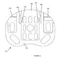
- FIG. 3is a diagrammatic representation illustrating one embodiment of inner face 130 of implant plate 110 .
- Inner face 130can include recessed portions to define channels 155 and channel 160 .
- channels 155receive an insertion tool.
- the sidewalls of channels 155can angled (e.g., dovetailed) or otherwise shaped to mate and form a frictional connection with the complementarily shaped insertion tool.
- Channels 155 and the complementary portion of the insertion toolcan be shaped so that the insertion tool is only removed from implant plate 110 by sliding the insertion tool out of channels 155 in the opposite direction from which it was inserted into channels 155 .
- the depth of insertion of the insertion toolcan be limited by the length of channels 155 , a stop in the channels, a stop on the insertion tool or by other mechanism.
- Channel 160can be shaped and sized to engage with spacer member 115 .
- the sidewalls of channel 160can also be angled (e.g., dovetailed) or otherwise shaped to capture spacer member 115 .
- Implant plate 110can include detents 165 with protrusions 170 that help prevent spacer member 115 from sliding out of channel 160 .
- Detents 165can be formed so that they return to approximately their original positions if pushed outward from the center of channel 160 . As spacer member 115 slides into channel 160 , detents 165 can push away from the center of channel 160 until protrusions 170 fit in complementary indentions in spacer member 115 (shown in FIG. 7 ).
- Protrusions 170 and the complementary indentionsmate to limit movement of implant plate 110 (and implant 112 ) relative to spacer member 115 .
- movementis limited so that spacer member 115 can not be easily removed from implant plate 110 .
- the mating connectionprevents implant plate 110 from sliding off of spacer member 115 during expected use as a spinal implant.
- the depth of insertion of spacer member 115can be limited by the length of channel 160 , a stop in channel 160 , a stop on spacer member 115 or end plate 120 or by other suitable mechanism.
- FIG. 4is a diagrammatic representation illustrating an end view of one embodiment of implant plate 110 . Assuming implant plate 110 is used in an anterior approach procedure, FIG. 4 is an anterior end view. As shown in FIG. 4 , implant plate 110 includes channels 155 open to the anterior end with dovetailed walls 175 . Similarly, implant plate 110 includes channel 160 open to the anterior end with dovetailed walls 180 . Walls 175 and 180 are angled so that the respective channels are wider closer to the outer face than the inner side of implant plate 110 . Channels 155 and 160 can be otherwise shaped to respectively receive the insertion device and spacer member 115 .
- FIG. 5is a diagrammatic representation of end views of other example channel shapes for receiving the insertion device or spacer member 115 . Keyhole, “T”, and partial “T” shapes are shown. The embodiments of FIG. 5 are provided by way of example and not limitation.
- FIG. 6is a diagrammatic representation of a cross-sectional view of one embodiment of an integrated end plate 120 and spacer member 115 .
- End plate 120can have be flat, curved or other suitable form factor for spinal surgery.
- Spacer member 115can be connected to or be integrated with plate 120 .
- the size of spacer member 115can be selected to provide the appropriate distance between implant plates 110 and 112 and depth of insertion.
- spacer member 115can be shaped so that a desired lordotic angle is achieved when implant 100 is inserted.
- spacer member 115can be a partial wedge shape so that the anterior height of spacer member 115 is different than the posterior height of spacer member 115 .
- Spacer member 115can include a cavity 195 that can be packed with bone growth material.
- End plate 120can include a passage 140 that opens to outer surface 143 of end plate 120 and the center of spacer member 115 to allow access to cavity 195 .
- FIG. 7is a diagrammatic representation of a top view of integrated end plate 120 and spacer member 115 .
- Spacer member 115can include indents 190 to capture protrusion 170 of implant plate 110 (shown in FIG. 3 ). As illustrated in FIG. 7 , spacer member 115 can also form a cavity 195 . Bone growth or other material can be packed in cavity 195 .
- FIG. 8is a diagrammatic representation of an end view of integrated end plate 120 and spacer member 115 .
- Spacer member 115has a complementary shape to channel 160 of the implant plates 110 and 112 so that a portion of spacer member 115 is captured by the sidewalls of channel 160 .
- spacer member 115can include tapered (or other shaped) flanges 197 that are captured by the dovetailed sidewalls of the respective channels 160 . When in place, the joint formed by channels 160 and flanges 197 prevent the implant plates from vertically separating from spacer member 115 .
- End plate 120can have a “bow” shape in which the upper and lower portions of end plate 120 are wider than the center portion. As discussed below in conjunction with FIG. 11 , this allows end plate 120 to limit the separation distance of an insertion tool.
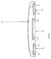
- FIG. 9is a diagrammatic representation of an end view of end plate 120 .
- FIG. 9represents an anterior view.
- End plate 120can include fastener holes 145 to allow end plate 120 to be fastened to adjacent vertebrae. Additionally, end plate 120 can include an opening to passage 140 to allow access to cavity 195 (shown in FIG. 7 ). End plate 120 can also include recessed feature 205 that can aid in alignment of a driver during insertion of spinal implant 100 .
- FIG. 10is a diagrammatic representation of one embodiment of a separator 200 (i.e., a portion of an insertion device) to insert implant 100 .
- Separator 200can include arms 210 and 212 .
- Arms 210 and 212can include respective attachment portions that couple separator 200 to respective arms of a spreader using a friction fit, mating fit or other suitable connection mechanism.
- Arm 210couples to implant plate 110 and arm 212 couples to implant plate 112 (e.g., through frictional connections or other connections).
- End plate 120 and spacer member 115are movably captured in a channel formed in separator 200 so that end plate 120 and spacer member 115 can slide toward implant plates 110 and 112 .
- FIG. 11is a diagrammatic representation of a bottom view of one embodiment of arm 212 .
- Arm 212can include prongs 215 shaped to fit corresponding channels in implant plate 112 (e.g., channels 155 shown in FIG. 3 ).
- prongs 215can be separated by a distance that is sufficient to straddle the center portion of end plate 120 but not the top and bottom portions of end plate 120 .
- the gap between prongs 215is greater than the width of the center of end plate 120 but less than the width of the top and bottom portions of end plate 120 . Consequently, prongs 215 (and the corresponding prongs on the arm 210 ) form a channel down which end plate 120 and the integrated or connected spacer member 115 can move.
- the bow shape or other shape of end plate 120limits the separation distance of arms 210 and 212 .
- Arm 212can define a passage 225 .
- This passagecan allow a driver (e.g., a slap hammer or other driver) access to end plate 120 .
- the drivercan assert a force on end plate 120 to move end plate 120 into position during implantation.
- passage 225allows materials to be added to end plate assembly 120 . For example material can be injected through passage 225 , passage 140 (shown in FIG. 2 ) into cavity 195 formed by spacer member 115 (shown in FIG. 7 ).
- FIGS. 12 a - cillustrate one embodiment of separator 200 and implant 100 during various stages of insertion.
- FIG. 12 aillustrates separator 200 from one side
- FIGS. 12 b and 12 cillustrate separator 200 from the opposite side during the procedure.
- a surgeoncan make an incision on the anterior side of the body during a discectomy procedure.
- Implant plates 110 and 112 , end plate 120 and spacer member 115can be loaded on separator 200 ( FIG. 12 a ) and separator 200 inserted into the body using a spreader such that implant plates 110 and 112 are inserted in the space created by removal or partial removal of a vertebral disc.
- Arms 210 and 212are separated to separate implant plates 110 and 112 ( FIG. 12 b ).
- the separation distancecan be limited by the geometry of end plate 120 or through another suitable mechanism.
- spacer member 115can be moved to join with implant plates 110 and 112 ( FIG. 12 c ).
- End plate 120can then be attached to the vertebral bodies using fasteners.
- Separator 200can be removed from implant plates 110 and 112 .
- Various portions or all of separator 200 and implant 100may be radiopaque or include radiopaque markers to allow viewing with medical imaging devices to ensure proper placement of implant 100 .
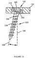
- FIG. 13depicts a cross-sectional view of an embodiment of one of the holes 145 (also shown in FIG. 2 ) in which screw 320 is disposed.
- Hole 145is preferably substantially spherical in shape so that a head 332 of screw 320 may be rotated and moved to various positions within borehole 312 .
- Ring 318is preferably sized to fit into hole 145 between plate 120 and head 332 .
- the outer surface of ring 318is preferably curved to permit movement of the ring within hole 145 .
- ring 318is like that of a ball and socket since ring 318 may be rotated both horizontally and vertically in clockwise and counterclockwise directions within hole 145 . Ring 318 may also be rotated in directions that are angled away from the horizontal and vertical directions.
- ring 318at least partially surrounds head 332 of screw 320 which is positioned within hole 145 .
- a shank 334 of bone screw 320preferably has threading 336 to allow the screw to be inserted into a bone when it is rotated in a clockwise direction.
- Head 332preferably includes a cavity 342 that extends from the top of the head to an inner portion of the head.
- Cavity 342may be shaped to receive the end of any fastening device e.g., a socket wrench that may be used to turn screw 320 .
- Screw 320may be simultaneously screwed into a bone and moved to its desired position.
- the inner surface of ring 318 and the outer surface of head 332are preferably tapered and shaped to mate with each other.
- the bottom portion of head 332is preferably smaller than the upper portion of ring 318 .
- head 332preferably applies a radial force to ring 318 , thereby causing the ring to expand within the hole and increase the size of the gap in ring 318 that allows ring 318 to expand.
- An interference fitmay form between screw head 332 , ring 318 , and plate 120 in which these elements fit so tightly together that they obstruct the movements of each other.
- the hoop stress of ring 318 on head 332may fixedly attach screw 320 to plate 120 .
- screw head 332 and ring 318may be positioned within hole 145 such that their left sides are at a higher elevation than their right sides.
- FIG. 13shows that positioning screw head 332 in this configuration may result in a centerline 338 of shank 334 being obliquely angulated with respect to plate 120 .
- centerline 338may be positioned where it is at an angle ranging from 0 to 15 degrees with respect to an imaginary axis 340 which is perpendicular to plate 120 .
- FIG. 13demonstrates shank 334 of screw 320 being angled to the left of imaginary axis 340 while FIG. 14 demonstrates shank 334 being angled to the right of imaginary axis 340 .
- Screw 320is not limited to these positions and can be angled in various directions, such as into the page.
- FIGS. 15 and 16depict different embodiments of end plate 120 with fasteners inserted.
- FIG. 15shows that screws 320 may be positioned within holes 145 such that they extend in converging directions with respect to each other.
- the screws 320 depicted in FIG. 16are shown as being positioned such that their shanks 334 extend in diverging directions with respect to each other. Screws 320 may be moved to such positions as described above. Since bone screws 320 may be placed in diverging or converging directions through holes 145 at both ends of plate 120 , screw backout may be greatly reduced. Further, the use of rings 318 to fixedly attach screws 320 to plate 120 may prevent damage to tissue structures by any screws that are able to escape from the bone.
- Rings 318preferably do not extend above the upper surface of plate 120 , and thus advantageously do not contact tissue structures.
- Screw 320may be placed in a uni-cortical position within the bone since the problem of screw backout is greatly reduced by the diverging or converging screw configurations.
- end plate 120is prepared for surgical implantation by pre-positioning of rings 318 within holes 145 .
- holesmay be drilled and tapped into the bones to which plate 120 is to be attached. Plate 120 may then be positioned adjacent to the bones when spacer member 115 is coupled to implant plate 110 and implant plate 112 .
- Each of the screws 320may be screwed into the bone holes while they are being positioned within their corresponding holes 145 .
- Each pair of screws 320 at opposite ends 120may be positioned so that shanks of the screws are at oblique angles relative to the plate.
- the insertion force of each screw 320 into each ring 318preferably causes the ring to exert a compressive force on the screw head, thereby fixably connecting the screws to plate 120 .
- FIG. 17A side view of another embodiment of a spinal plate 120 and fasteners is shown in FIG. 17 .
- This embodimentincludes a bone screw 420 and a ring 418 .
- Plate 120may be used to stabilize a bony structure such as the spine to facilitate a bone fusion (e.g., a spinal fusion).
- the bone screw 420may be used to connect plate 120 to a bone such as a vertebra.
- Ring 418preferably fixes bone screw 420 to plate 120 at a selected angle that depends upon the patient's anatomy.
- each hole 145preferably has a curvate inner surface 413 for engaging the outer surface 423 of ring 418 .
- the inner surface 413preferably has the shape of a portion of an outer surface of a sphere.
- Hole 145has a width that is defined across the inner surface 413 of the borehole.
- the width of the boreholemay vary in a direction axially through the borehole.
- the width of the holespreferably increases from a surface of the plate to about the middle of the plate.
- the width of the hole 145preferably decreases from about the middle of the plate to an opposite surface of the plate such that the hole has a maximum width near the midpoint between the surfaces.
- the outer surface 423 of ring 418is preferably curvate for engaging the inner surface 413 of the borehole.
- the shape of surfaces 423 and 413preferably allow ring 418 to swivel within the borehole.
- the swiveling actionmay be similar to that of a ball and socket joint.
- the ringpreferably surrounds at least a portion of the head 425 of a bone screw.
- the enlarged end 427 disposed on head 425is optional and need not be included if it inhibits angulation of the bone screw.
- the swiveling of the ring within the boreholepreferably enables the shank 435 of the bone screw 420 to rotate in a substantially conical range of motion. In this manner, the head is preferably movable within the borehole, and the shank is adjustably positionable at a plurality of angles substantially oblique to the plate.
- the surfaces 423 and 413are preferably shaped to provide a conical range of motion to the shank that is within a preferred range of angles.
- the headis preferably movable within the borehole such that the shank can be positioned at a selected angle relative to an imaginary axis running perpendicular to the plate proximate borehole 145 .
- the selected angleis preferably less than about 45 degrees, more preferably less than about 30 degrees, and more preferably still less than about 15 degrees.
- Ring 418preferably has an outer width that is less than or about equal to the width of hole 145 at a location between the surfaces of plate 120 . In this manner, ring 418 may be positioned within hole 145 proximate the middle of the hole to enable the bone screw 420 to extend substantially perpendicularly from the bone plate 120 .
- rings 418Prior to surgery, rings 418 are preferably pre-positioned within holes 145 of plate 120 , “Pre-positioned” is taken to mean that the rings are capable of swiveling within the borehole but are preferably inhibited from falling out of the borehole because of the reduced width of the borehole proximate the upper and lower surfaces.
- the width of the borehole proximate the upper and lower surfaces of plate 120is preferably less than or about equal to the outer width of the ring to inhibit the ring from falling out of the borehole. In this manner, the surgeon may use a plate 120 having rings 418 pre-positioned within the holes 145 such that the rings will not fall into the surgical wound when implant 100 is installed.
- the rings 418can be manually positioned within holes 145 during surgery.
- Ring 418preferably includes one or more slots or gaps. The slot preferable allows the ring to be contracted or expanded. Contraction of ring 418 may allow the ring to be positioned within the borehole during surgery. Once positioned within the borehole the ring preferably expands and is inhibited from falling out of the borehole.
- the ring 418is preferably capable of being swiveled such that one portion of the ring is adjacent to one surface of plate 120 while another portion of the ring lies adjacent to the opposite surface of plate 120 .
- Ring 418is preferably sufficiently thin to allow it to reside within the borehole without extending from the borehole beyond the surfaces of plate 120 .
- the ring and screw headremain within the hole 145 to minimize the profile of implant 100 .
- the bone screw 420may be capable of being angulated relative to the plate 120 such that ring 418 extends from the hole 145 beyond a surface of the plate 120 .
- the head 425is preferably screwed into ring 418 to create a fixed connection between bone screw 420 and plate 120 at a selected angle.
- screw head 425preferably contains head threading 421 on its outer surface that is complementary to ring threading 419 contained on the inner surface of ring 418 .
- the head threading 421preferably mates with the ring threading 419 to enhance the connection between the bone screw 420 and the ring 418 .
- the head 425preferably has a cavity 442 formed on its upper surface for receiving a driving tool such as a screw driver or an alien wrench.
- the head threading 421 on the head 425 and the ring threading 419 on the inner surface of ring 418is preferably substantially fine relative to the threading 436 on bone screw 420 . That is, the pitch of the head threading 421 and ring threading 419 is preferably smaller than that on bone screw 420 .
- the ring threading 419preferably has multiple starts to facilitate connection of the bone screw and the ring. In one embodiment, the ring threading 419 has a double start such that the head can be started into the ring threading at either one of two orientations offset by 180 degrees. In another embodiment, the ring threading has a triple start such that the head can be started into the ring threading at any one of three orientations offset by 420 degrees.
- the ring threading 419 and head threading 421are preferably pitched to a substantially similar degree to the threading 436 on the bone screw 420 .
- the ring threading 419 and head threading 421are pitched such that the head 425 causes expansion of the ring 418 while the bone screw 420 is being inserted into the bone.
- holesmay be drilled and tapped into the bones to which plate 120 is to be attached.
- Plate 120may then be positioned adjacent to the bones.
- a ring 418may be positioned within the borehole.
- a bone screw 420may be positioned through ring 418 such that the head threading 421 of head 425 engages the ring threading 419 of ring 418 .
- the bone screw 420may then be rotated to insert the bone screw into the bone.
- the head threads and ring threadspreferably interact such that the head is moved into the ring. Movement of the head 425 into the ring 418 preferably causes the ring to expand such that the orientation of the bone screw 420 relative to the plate 120 is fixed.
- the ring threading and head threadingis pitched such the orientation of the bone screw 420 is fixed after plate 120 engages the bone.
- the bone screwsmay be used in pairs to prevent screw backout.
- the bone screwsare preferably positioned into the bone in substantially converging or substantially diverging directions relative to one another.
- the outer surface of the head 425is preferably tapered so that screwing the head into the ring causes a change in width (e.g., expansion) of the ring 418 to fix the bone screw 420 in position relative to the plate 120 .
- the inner surface of the ring 418may also be tapered to substantially match the taper on the outer surface of the head. At least a portion of the head 425 preferably has a width greater than the inner width of the ring 418 . As the screw head is screwed into the ring 418 , the ring preferably expands outwardly from its inner surface to accommodate the increasing width of the screw head 425 .
- the ring 418may contain a slot or gap as previously described to facilitate expansion of the ring against the inner surface 413 of the hole 145 .
- the slotis preferably widened as a result of force received from head 425 .
- the force exerted by head 425 against the inner surface of ring 418preferably presses the ring into a fixed engagement against inner surface 413 of hole 145 .
- ring 418may contain one or more partial slots 445 , as depicted in FIG. 19 .
- Each partial slot 445preferably extends from a top 447 or bottom 449 of ring 418 into the ring. Partial slots may extend up to about midpoint 448 of ring 418 .
- a plurality of slots 445may be oriented about the ring such that alternate slots extend from the top 447 and/or the bottom 449 of ring 418 , as depicted in FIG. 19 . These alternating partial slots preferably facilitate the expansion and contraction of ring 418 .
- FIGS. 20A and 20BCross-sectional views of two embodiments of ring 418 having threaded section 419 are shown in FIGS. 20A and 20B .
- the ringmay contain an inner surface that is tapered (as shown in FIG. 20A ) or that is substantially untapered (as shown in FIG. 20B ).
- Cross-sectional views of two embodiments of screw 420are shown in FIGS. 21A and 21B .
- the head 425may have a substantially untapered outer surface (as shown in FIG. 21A ) or a substantially tapered outer surface (as shown in FIG. 21B ).
- each of the heads of the screws depicted in FIGS. 21A and 21Bmay be used in combination with either of the rings 418 depicted in FIGS. 20A and 20B .
- the head of the screwmay include an outer surface having a substantially untapered portion along with a tapered portion proximate its end for expanding the ring 418 .
- a “ring”is taken to mean any member capable of fitting between the inner surface 413 of a fastener hole and the bone screw 420 to connect the bone screw to the plate 120 .
- the ringis preferably substantially circular to surround head 425 , but the ring may instead have a non-circular shape.
- the ringmay be made of a number of biocompatible materials including metals, plastics, and composites.
- a stronger connection between the bone screw 420 and the plate 120may be formed by texturing either outer surface 431 of head 425 of bone screw 420 or inner surface 433 of ring 418 , as depicted in FIG. 22 .
- both surfacesare textured to inhibit movement of the bone screw with respect to the plate.
- outer surface 431 of head 425 and inner surface 433 of ring 418may be formed as relatively smooth surfaces. While the friction between these smooth surfaces tends to be sufficient to maintain bone screw 420 in a fixed position with respect to plate 120 , under stressful conditions the bone screw may be forced out of ring 418 .
- the coefficient of friction of the surfacemay be increased so that a large amount of force is needed to overcome the frictional connection between head 425 of bone screw 420 and ring 418 . This increase in friction between bone screw 420 and ring 418 may further inhibit screw backout from plate 120 .
- a number of textured surfacesmay be used to increase the coefficient of friction between ring 418 and head 425 of bone screw 420 .
- any process which transforms a relatively smooth surface into a roughened surface having an increased coefficient of frictionmay be used.
- Methods for forming a roughened surfaceinclude, but are not limited to: sanding, forming grooves within a surface, ball peening processes, electric discharge processes, and embedding of hard particles within a surface.
- a plurality of groovesmay be formed in outer surface 431 of head 425 of bone screw 420 or inner surface 433 of ring 418 .
- a plurality of groovesis formed in both outer surface 431 and inner surface 433 . While it is preferred that both outer surface 431 and the inner surface 433 (is the lead line for 433 in the right place?) be textured, texturing of only one of the surfaces may be sufficient to attain additional resistance to movement.
- the frictional surfacemay be created by an electrical discharge process.
- An electrical discharge processis based on the principle of removal of portions of a metal surface by spark discharges. Typically a spark is generated between the surface to be treated and an electrode by creating potential differential between the tool and the electrode. The spark produced tends to remove a portion of the surface disposed between the electrode and the surface.
- the electrodeis relatively small such that only small portions of the surface are removed.
- By moving the electrode about the surfacenumerous cavities may be formed within the surface. Typically these cavities are somewhat pyramidal in shape. Various patterns may be formed within the surface depending on how the electrode is positioned during the discharge. Electric discharge machines are well known in the art. A method for forming a frictional surface within a metal surface using an electric discharge process is described in U.S. Pat. No. 4,964,641 to Miesch et al. which is incorporated by reference as if set forth herein.
- a variety of patternsmay be formed using an electric discharge machine.
- a diamond pattern or a waffle patternis formed on either inner surface 433 of ring 418 or outer surface 431 of head 425 of bone screw 420 .
- inner surface 431 of ring 418 and/or outer surface 433 of head 125 of bone screw 120may be textured by the use of a shot peening process.
- a shot peening process for forming a textured surfaceis described in U.S. Pat. No. 5,526,664 to Vetter which is incorporated by reference as if set forth herein.
- a shot peening processinvolves propelling a stream of hardened balls, typically made of steel, at a relatively high velocity at a surface. To create a pattern upon an area of the surface the stream is typically moved about the surface. The speed by which the stream is moved about the surface tends to determine the type of textured surface formed.
- the streamis moved such that a pattern resulting in a textured surface having ridges and valleys is formed on inner surface 433 of ring 418 and outer surface 431 of head 425 of bone screw 420 .
- the ridges and valleysmay interact with each other to provide additional resistance to movement in either a longitudinal direction or a direction perpendicular to the longitudinal axis.
- the textured surfacemay be produced by embedding sharp hardened particles in the surface.
- a method for embedding sharp hardened particles in a metal surfaceis described in U.S. Pat. No. 4,768,787 to Shira which is incorporated by reference as if set forth herein.
- the method of Shirainvolves using a laser or other high energy source to heat the surface such that the surface melts in selected areas. Just before the molten area re-solidifies, a stream of abrasive particles is directed to the area. In this manner some of the particles tend to become embedded within the molten surface.
- the particlestypically have a number of sharp edges that protrude from the surface after the particles have been embedded within the surface.
- outer surface 431 of head 425 of bone screw 420may be textured using a pattern of grooves.
- Inner surface of ring 418may be textured using an electrical discharge method. When coupled together the textured surfaces of bone screw 420 and ring 418 may interact with each other to provide additional resistance to movement in either a longitudinal direction or a direction perpendicular to the longitudinal axis.
- Textured surfacesmay also be formed on any of the other surfaces of the plate system. The formation of textured surfaces preferably increases the frictional resistance between the various components of the plate system.
Landscapes
- Health & Medical Sciences (AREA)
- Engineering & Computer Science (AREA)
- Biomedical Technology (AREA)
- Orthopedic Medicine & Surgery (AREA)
- Neurology (AREA)
- Transplantation (AREA)
- Life Sciences & Earth Sciences (AREA)
- Animal Behavior & Ethology (AREA)
- Veterinary Medicine (AREA)
- Public Health (AREA)
- General Health & Medical Sciences (AREA)
- Heart & Thoracic Surgery (AREA)
- Vascular Medicine (AREA)
- Oral & Maxillofacial Surgery (AREA)
- Cardiology (AREA)
- Physical Education & Sports Medicine (AREA)
- Surgery (AREA)
- Nuclear Medicine, Radiotherapy & Molecular Imaging (AREA)
- Medical Informatics (AREA)
- Molecular Biology (AREA)
- Prostheses (AREA)
Abstract
Description
Claims (17)
Priority Applications (4)
| Application Number | Priority Date | Filing Date | Title |
|---|---|---|---|
| US11/752,200US8480715B2 (en) | 2007-05-22 | 2007-05-22 | Spinal implant system and method |
| PCT/US2008/061933WO2008147621A1 (en) | 2007-05-22 | 2008-04-30 | Spinal implant system and method |
| EP08747133AEP2162100A1 (en) | 2007-05-22 | 2008-04-30 | Spinal implant system and method |
| US13/936,495US20130282127A1 (en) | 2007-05-22 | 2013-07-08 | Spinal implant system and method |
Applications Claiming Priority (1)
| Application Number | Priority Date | Filing Date | Title |
|---|---|---|---|
| US11/752,200US8480715B2 (en) | 2007-05-22 | 2007-05-22 | Spinal implant system and method |
Related Parent Applications (1)
| Application Number | Title | Priority Date | Filing Date |
|---|---|---|---|
| US12/489,566Continuation-In-PartUS9089256B2 (en) | 2007-06-13 | 2009-06-23 | Medical robotic system providing an auxiliary view including range of motion limitations for articulatable instruments extending out of a distal end of an entry guide |
Related Child Applications (2)
| Application Number | Title | Priority Date | Filing Date |
|---|---|---|---|
| US12/780,071Continuation-In-PartUS8620473B2 (en) | 2007-06-13 | 2010-05-14 | Medical robotic system with coupled control modes |
| US13/936,495ContinuationUS20130282127A1 (en) | 2007-05-22 | 2013-07-08 | Spinal implant system and method |
Publications (2)
| Publication Number | Publication Date |
|---|---|
| US20080294260A1 US20080294260A1 (en) | 2008-11-27 |
| US8480715B2true US8480715B2 (en) | 2013-07-09 |
Family
ID=39563612
Family Applications (2)
| Application Number | Title | Priority Date | Filing Date |
|---|---|---|---|
| US11/752,200Expired - Fee RelatedUS8480715B2 (en) | 2007-05-22 | 2007-05-22 | Spinal implant system and method |
| US13/936,495AbandonedUS20130282127A1 (en) | 2007-05-22 | 2013-07-08 | Spinal implant system and method |
Family Applications After (1)
| Application Number | Title | Priority Date | Filing Date |
|---|---|---|---|
| US13/936,495AbandonedUS20130282127A1 (en) | 2007-05-22 | 2013-07-08 | Spinal implant system and method |
Country Status (3)
| Country | Link |
|---|---|
| US (2) | US8480715B2 (en) |
| EP (1) | EP2162100A1 (en) |
| WO (1) | WO2008147621A1 (en) |
Cited By (32)
| Publication number | Priority date | Publication date | Assignee | Title |
|---|---|---|---|---|
| US20120172989A1 (en)* | 2009-04-27 | 2012-07-05 | Mccarthy Kevin | Vertebral osteosynthetis equipment |
| WO2016077606A1 (en)* | 2014-11-12 | 2016-05-19 | Medivest, Llc | Spinal spacing implant, spinal spacer assembly, expander and insertion instrument, kit and methods of assembly and use |
| US9566169B2 (en) | 2014-03-13 | 2017-02-14 | DePuy Synthes Products, Inc. | ACIS allograft designs |
| US9724207B2 (en) | 2003-02-14 | 2017-08-08 | DePuy Synthes Products, Inc. | In-situ formed intervertebral fusion device and method |
| US9949769B2 (en) | 2004-03-06 | 2018-04-24 | DePuy Synthes Products, Inc. | Dynamized interspinal implant |
| US10433974B2 (en) | 2003-06-30 | 2019-10-08 | DePuy Synthes Products, Inc. | Intervertebral implant with conformable endplate |
| US10888433B2 (en) | 2016-12-14 | 2021-01-12 | DePuy Synthes Products, Inc. | Intervertebral implant inserter and related methods |
| US10940016B2 (en) | 2017-07-05 | 2021-03-09 | Medos International Sarl | Expandable intervertebral fusion cage |
| US10966840B2 (en) | 2010-06-24 | 2021-04-06 | DePuy Synthes Products, Inc. | Enhanced cage insertion assembly |
| US10973652B2 (en) | 2007-06-26 | 2021-04-13 | DePuy Synthes Products, Inc. | Highly lordosed fusion cage |
| US11273050B2 (en) | 2006-12-07 | 2022-03-15 | DePuy Synthes Products, Inc. | Intervertebral implant |
| US11278420B2 (en) | 2019-10-25 | 2022-03-22 | Zavation, Llc | Recessed pocket spinal implant |
| US11344424B2 (en) | 2017-06-14 | 2022-05-31 | Medos International Sarl | Expandable intervertebral implant and related methods |
| US11426286B2 (en) | 2020-03-06 | 2022-08-30 | Eit Emerging Implant Technologies Gmbh | Expandable intervertebral implant |
| US11426290B2 (en) | 2015-03-06 | 2022-08-30 | DePuy Synthes Products, Inc. | Expandable intervertebral implant, system, kit and method |
| US11446156B2 (en) | 2018-10-25 | 2022-09-20 | Medos International Sarl | Expandable intervertebral implant, inserter instrument, and related methods |
| US11446155B2 (en) | 2017-05-08 | 2022-09-20 | Medos International Sarl | Expandable cage |
| US11452607B2 (en) | 2010-10-11 | 2022-09-27 | DePuy Synthes Products, Inc. | Expandable interspinous process spacer implant |
| US11497619B2 (en) | 2013-03-07 | 2022-11-15 | DePuy Synthes Products, Inc. | Intervertebral implant |
| US11510788B2 (en) | 2016-06-28 | 2022-11-29 | Eit Emerging Implant Technologies Gmbh | Expandable, angularly adjustable intervertebral cages |
| US11596523B2 (en) | 2016-06-28 | 2023-03-07 | Eit Emerging Implant Technologies Gmbh | Expandable and angularly adjustable articulating intervertebral cages |
| US11602438B2 (en) | 2008-04-05 | 2023-03-14 | DePuy Synthes Products, Inc. | Expandable intervertebral implant |
| US11607321B2 (en) | 2009-12-10 | 2023-03-21 | DePuy Synthes Products, Inc. | Bellows-like expandable interbody fusion cage |
| US11612491B2 (en) | 2009-03-30 | 2023-03-28 | DePuy Synthes Products, Inc. | Zero profile spinal fusion cage |
| US11654033B2 (en) | 2010-06-29 | 2023-05-23 | DePuy Synthes Products, Inc. | Distractible intervertebral implant |
| US11737881B2 (en) | 2008-01-17 | 2023-08-29 | DePuy Synthes Products, Inc. | Expandable intervertebral implant and associated method of manufacturing the same |
| US11752009B2 (en) | 2021-04-06 | 2023-09-12 | Medos International Sarl | Expandable intervertebral fusion cage |
| US11850160B2 (en) | 2021-03-26 | 2023-12-26 | Medos International Sarl | Expandable lordotic intervertebral fusion cage |
| US11911287B2 (en) | 2010-06-24 | 2024-02-27 | DePuy Synthes Products, Inc. | Lateral spondylolisthesis reduction cage |
| USRE49973E1 (en) | 2013-02-28 | 2024-05-21 | DePuy Synthes Products, Inc. | Expandable intervertebral implant, system, kit and method |
| US12090064B2 (en) | 2022-03-01 | 2024-09-17 | Medos International Sarl | Stabilization members for expandable intervertebral implants, and related systems and methods |
| US12440346B2 (en) | 2023-03-31 | 2025-10-14 | DePuy Synthes Products, Inc. | Expandable intervertebral implant |
Families Citing this family (50)
| Publication number | Priority date | Publication date | Assignee | Title |
|---|---|---|---|---|
| FR2897259B1 (en) | 2006-02-15 | 2008-05-09 | Ldr Medical Soc Par Actions Si | INTERSOMATIC TRANSFORAMINAL CAGE WITH INTERBREBAL FUSION GRAFT AND CAGE IMPLANTATION INSTRUMENT |
| FR2824261B1 (en) | 2001-05-04 | 2004-05-28 | Ldr Medical | INTERVERTEBRAL DISC PROSTHESIS AND IMPLEMENTATION METHOD AND TOOLS |
| FR2827156B1 (en) | 2001-07-13 | 2003-11-14 | Ldr Medical | VERTEBRAL CAGE DEVICE WITH MODULAR FASTENING |
| FR2846550B1 (en) | 2002-11-05 | 2006-01-13 | Ldr Medical | INTERVERTEBRAL DISC PROSTHESIS |
| FR2858546B1 (en) | 2003-08-04 | 2006-04-28 | Spine Next Sa | INTERVERTEBRAL DISC PROSTHESIS |
| FR2865629B1 (en) | 2004-02-04 | 2007-01-26 | Ldr Medical | INTERVERTEBRAL DISC PROSTHESIS |
| EP2113227B1 (en) | 2004-02-04 | 2015-07-29 | LDR Medical | Intervertebral disc prosthesis |
| FR2869528B1 (en) | 2004-04-28 | 2007-02-02 | Ldr Medical | INTERVERTEBRAL DISC PROSTHESIS |
| FR2879436B1 (en) | 2004-12-22 | 2007-03-09 | Ldr Medical | INTERVERTEBRAL DISC PROSTHESIS |
| FR2891135B1 (en) | 2005-09-23 | 2008-09-12 | Ldr Medical Sarl | INTERVERTEBRAL DISC PROSTHESIS |
| FR2893838B1 (en) | 2005-11-30 | 2008-08-08 | Ldr Medical Soc Par Actions Si | PROSTHESIS OF INTERVERTEBRAL DISC AND INSTRUMENTATION OF INSERTION OF THE PROSTHESIS BETWEEN VERTEBRATES |
| US8465546B2 (en) | 2007-02-16 | 2013-06-18 | Ldr Medical | Intervertebral disc prosthesis insertion assemblies |
| FR2916956B1 (en) | 2007-06-08 | 2012-12-14 | Ldr Medical | INTERSOMATIC CAGE, INTERVERTEBRAL PROSTHESIS, ANCHORING DEVICE AND IMPLANTATION INSTRUMENTATION |
| CN105326585B (en) | 2009-09-17 | 2018-12-11 | Ldr控股公司 | Intervertebral implant with extensible bone anchoring element |
| WO2011080535A1 (en) | 2009-12-31 | 2011-07-07 | Lrd Medical | Anchoring device, intervertebral implant and implantation instrument |
| US8945227B2 (en)* | 2010-02-01 | 2015-02-03 | X-Spine Systems, Inc. | Spinal implant co-insertion system and method |
| US8377139B2 (en) | 2010-06-17 | 2013-02-19 | Aesculap Implant Systems, Llc | Standalone interbody fusion device with locking and release mechanism |
| CA2829565A1 (en)* | 2011-03-10 | 2012-09-13 | DePuy Synthes Products, LLC | Awl screw fixation members and related systems |
| US9277946B2 (en)* | 2011-09-06 | 2016-03-08 | Amendia, Inc. | Spinal fusion system |
| US20140058446A1 (en)* | 2011-09-28 | 2014-02-27 | Avi Bernstein | Spinal implant system |
| US9198764B2 (en) | 2012-01-31 | 2015-12-01 | Blackstone Medical, Inc. | Intervertebral disc prosthesis and method |
| FR2987256B1 (en) | 2012-02-24 | 2014-08-08 | Ldr Medical | ANCHORING DEVICE FOR INTERVERTEBRAL IMPLANT, INTERVERTEBRAL IMPLANT AND IMPLANTATION INSTRUMENTATION |
| CN104519812B (en)* | 2012-03-28 | 2018-04-10 | 费瑟特-链接公司 | The reinforcing implant for vertebral plate with cantilevered bridgeware |
| US10076364B2 (en) | 2012-06-29 | 2018-09-18 | K2M, Inc. | Minimal-profile anterior cervical plate and cage apparatus and method of using same |
| GB2507965B (en)* | 2012-11-14 | 2018-12-19 | Steris Instrument Man Services Inc | Cage assembly for tibial tuberosity advancement procedure |
| US10327910B2 (en) | 2013-03-14 | 2019-06-25 | X-Spine Systems, Inc. | Spinal implant and assembly |
| FR3005569B1 (en) | 2013-05-16 | 2021-09-03 | Ldr Medical | VERTEBRAL IMPLANT, VERTEBRAL IMPLANT FIXATION DEVICE AND IMPLANTATION INSTRUMENTATION |
| PL3052054T3 (en) | 2013-10-02 | 2020-06-29 | Motion Medical | Spinal implant for interbody use |
| WO2015048997A1 (en)* | 2013-10-02 | 2015-04-09 | Vigas | Spinal implant for interbody use |
| FR3016793B1 (en) | 2014-01-30 | 2021-05-07 | Ldr Medical | ANCHORING DEVICE FOR SPINAL IMPLANT, SPINAL IMPLANT AND IMPLANTATION INSTRUMENTATION |
| FR3020756B1 (en) | 2014-05-06 | 2022-03-11 | Ldr Medical | VERTEBRAL IMPLANT, VERTEBRAL IMPLANT FIXATION DEVICE AND IMPLANT INSTRUMENTATION |
| US9561113B2 (en)* | 2014-12-23 | 2017-02-07 | Globus Medical, Inc. | Vertebral implants and methods for installation thereof |
| CA2983488C (en)* | 2015-04-24 | 2020-12-22 | Biomet Manufacturing, Llc | Clavicle implants |
| KR101658320B1 (en)* | 2015-07-07 | 2016-09-20 | 이종호 | variable cross-sectioned orthodontic archwire equipped with integrated hook |
| US10130402B2 (en)* | 2015-09-25 | 2018-11-20 | Globus Medical, Inc. | Bone fixation devices having a locking feature |
| WO2018040240A1 (en)* | 2016-08-30 | 2018-03-08 | 北京市富乐科技开发有限公司 | Zero-incisura spinal fusion cage system |
| US10925747B2 (en)* | 2016-10-19 | 2021-02-23 | Imds Llc | Intervertebral cage |
| EP4108194A1 (en) | 2018-03-02 | 2022-12-28 | Stryker European Holdings I, LLC | Bone plates and associated screws |
| AU2019342137A1 (en) | 2018-09-20 | 2021-03-25 | Spinal Elements, Inc. | Spinal implant device |
| GB201818849D0 (en) | 2018-11-19 | 2019-01-02 | Axis Spine Tech Ltd | Intervertebral devices |
| US20230038323A1 (en)* | 2018-11-19 | 2023-02-09 | Axis Spine Technologies Ltd | Intervertebral devices |
| GB201902002D0 (en) | 2019-02-13 | 2019-04-03 | Axis Spine Tech Ltd | Intervertebral devices |
| GB201818850D0 (en)* | 2018-11-19 | 2019-01-02 | Axis Spine Tech Ltd | Intervertebral devices |
| GB201818847D0 (en)* | 2018-11-19 | 2019-01-02 | Axis Spine Tech Ltd | Intervertebral devices |
| US11219536B2 (en) | 2019-05-01 | 2022-01-11 | Simplify Medical Pty Ltd | Intervertebral prosethetic disc placement and removal systems |
| US11633219B2 (en)* | 2019-06-26 | 2023-04-25 | Globus Medical, Inc. | Fenestrated pedicle nail |
| GB201910668D0 (en) | 2019-07-25 | 2019-09-11 | Axis Spine Tech Ltd | Assemblies for and methods of determing height and angle of an intervertebral device |
| GB201910640D0 (en) | 2019-07-25 | 2019-09-11 | Axis Spine Tech Ltd | Insertions instruments |
| US11911284B2 (en) | 2020-11-19 | 2024-02-27 | Spinal Elements, Inc. | Curved expandable interbody devices and deployment tools |
| WO2022133456A1 (en) | 2020-12-17 | 2022-06-23 | Spinal Elements, Inc. | Spinal implant device |
Citations (362)
| Publication number | Priority date | Publication date | Assignee | Title |
|---|---|---|---|---|
| US3486505A (en) | 1967-05-22 | 1969-12-30 | Gordon M Morrison | Orthopedic surgical instrument |
| US4143332A (en) | 1975-11-13 | 1979-03-06 | Compagnie Generale D'electricite S.A. | Wave-length selective cut-out device |
| US4388921A (en) | 1980-05-28 | 1983-06-21 | Institut Straumann Ag | Device comprising a plate and screws for fastening a plate to a bone |
| US4401112A (en) | 1980-09-15 | 1983-08-30 | Rezaian Seyed M | Spinal fixator |
| US4433677A (en) | 1981-05-29 | 1984-02-28 | Max Bernhard Ulrich | Implantable splint for correcting lumbosacral spondylodesis |
| US4492226A (en) | 1979-10-10 | 1985-01-08 | Vsesojuzny Nauchno-Issledovatelsky I Ispytatelny Institut Meditsinskoi Tekhniki | Device for uniting bone fragments |
| US4501269A (en) | 1981-12-11 | 1985-02-26 | Washington State University Research Foundation, Inc. | Process for fusing bone joints |
| US4503848A (en) | 1981-04-08 | 1985-03-12 | Aesculap-Werke Aktiengesellschaft | Osteosynthesis plate |
| US4570618A (en) | 1983-11-23 | 1986-02-18 | Henry Ford Hospital | Intervertebral body wire stabilization |
| US4599086A (en)* | 1985-06-07 | 1986-07-08 | Doty James R | Spine stabilization device and method |
| US4604995A (en) | 1984-03-30 | 1986-08-12 | Stephens David C | Spinal stabilizer |
| US4641636A (en) | 1983-05-04 | 1987-02-10 | Cotrel Yves P C A | Device for supporting the rachis |
| US4643178A (en) | 1984-04-23 | 1987-02-17 | Fabco Medical Products, Inc. | Surgical wire and method for the use thereof |
| US4697586A (en) | 1986-06-24 | 1987-10-06 | Gazale William J | Combined chisel-guide surgical instrument |
| US4714469A (en) | 1987-02-26 | 1987-12-22 | Pfizer Hospital Products Group, Inc. | Spinal implant |
| US4743256A (en) | 1985-10-04 | 1988-05-10 | Brantigan John W | Surgical prosthetic implant facilitating vertebral interbody fusion and method |
| WO1988003781A1 (en) | 1986-11-25 | 1988-06-02 | Synthes Ag | Osteosynthetic device |
| US4763644A (en) | 1984-02-28 | 1988-08-16 | Webb Peter J | Spinal fixation |
| US4768787A (en) | 1987-06-15 | 1988-09-06 | Shira Chester S | Golf club including high friction striking face |
| SU1424826A1 (en) | 1986-05-22 | 1988-09-23 | Белорусский научно-исследовательский институт травматологии и ортопедии | Fixative for spinal column |
| US4805602A (en) | 1986-11-03 | 1989-02-21 | Danninger Medical Technology | Transpedicular screw and rod system |
| US4834757A (en) | 1987-01-22 | 1989-05-30 | Brantigan John W | Prosthetic implant |
| US4863476A (en) | 1986-08-29 | 1989-09-05 | Shepperd John A N | Spinal implant |
| US4887596A (en) | 1988-03-02 | 1989-12-19 | Synthes (U.S.A.) | Open backed pedicle screw |
| US4946458A (en) | 1986-04-25 | 1990-08-07 | Harms Juergen | Pedicle screw |
| US4950269A (en) | 1988-06-13 | 1990-08-21 | Acromed Corporation | Spinal column fixation device |
| US4961740A (en) | 1988-10-17 | 1990-10-09 | Surgical Dynamics, Inc. | V-thread fusion cage and method of fusing a bone joint |
| US4964641A (en) | 1990-01-26 | 1990-10-23 | Diversified Metal Incorporated | Golf club with electrical discharge machined face |
| US4966600A (en) | 1989-01-26 | 1990-10-30 | Songer Robert J | Surgical securance method |
| US4987892A (en) | 1989-04-04 | 1991-01-29 | Krag Martin H | Spinal fixation device |
| US5005562A (en) | 1988-06-24 | 1991-04-09 | Societe De Fabrication De Material Orthopedique | Implant for spinal osteosynthesis device, in particular in traumatology |
| US5047029A (en) | 1988-06-10 | 1991-09-10 | Synthes (U.S.A.) | Clamp and system for internal fixation |
| US5055104A (en) | 1989-11-06 | 1991-10-08 | Surgical Dynamics, Inc. | Surgically implanting threaded fusion cages between adjacent low-back vertebrae by an anterior approach |
| US5074864A (en) | 1988-12-21 | 1991-12-24 | Zimmer, Inc. | Clamp assembly for use in a spinal system |
| US5102412A (en) | 1990-06-19 | 1992-04-07 | Chaim Rogozinski | System for instrumentation of the spine in the treatment of spinal deformities |
| US5108399A (en) | 1988-09-17 | 1992-04-28 | Boehringer Ingelheim Gmbh | Device for osteosynthesis and process for producing it |
| US5108446A (en) | 1990-11-26 | 1992-04-28 | Sulzer Brothers Limited | Hip joint prosthesis |
| US5116340A (en) | 1989-01-26 | 1992-05-26 | Songer Robert J | Surgical securance apparatus |
| US5123926A (en) | 1991-02-22 | 1992-06-23 | Madhavan Pisharodi | Artificial spinal prosthesis |
| US5127912A (en) | 1990-10-05 | 1992-07-07 | R. Charles Ray | Sacral implant system |
| US5129388A (en) | 1989-02-09 | 1992-07-14 | Vignaud Jean Louis | Device for supporting the spinal column |
| US5129904A (en) | 1986-08-05 | 1992-07-14 | Illi Oscar E | Osteosynthetic implant |
| US5147359A (en) | 1988-12-21 | 1992-09-15 | Zimmer, Inc. | Spinal hook body |
| US5154718A (en) | 1988-12-21 | 1992-10-13 | Zimmer, Inc. | Spinal coupler assembly |
| US5171278A (en) | 1991-02-22 | 1992-12-15 | Madhavan Pisharodi | Middle expandable intervertebral disk implants |
| US5176678A (en) | 1991-03-14 | 1993-01-05 | Tsou Paul M | Orthopaedic device with angularly adjustable anchor attachments to the vertebrae |
| US5176680A (en) | 1990-02-08 | 1993-01-05 | Vignaud Jean Louis | Device for the adjustable fixing of spinal osteosynthesis rods |
| US5192321A (en) | 1989-03-29 | 1993-03-09 | Andrew Strokon | Apparatus and method for knee surgery |
| US5192327A (en) | 1991-03-22 | 1993-03-09 | Brantigan John W | Surgical prosthetic implant for vertebrae |
| US5201734A (en) | 1988-12-21 | 1993-04-13 | Zimmer, Inc. | Spinal locking sleeve assembly |
| US5242448A (en) | 1991-08-01 | 1993-09-07 | Pettine Kenneth A | Bone probe |
| US5242445A (en) | 1991-12-05 | 1993-09-07 | Danek Medical, Inc. | Split eyebolt for spinal rod |
| US5246442A (en) | 1991-12-31 | 1993-09-21 | Danek Medical, Inc. | Spinal hook |
| US5261909A (en) | 1992-02-18 | 1993-11-16 | Danek Medical, Inc. | Variable angle screw for spinal implant system |
| US5263953A (en) | 1991-12-31 | 1993-11-23 | Spine-Tech, Inc. | Apparatus and system for fusing bone joints |
| US5281222A (en) | 1992-06-30 | 1994-01-25 | Zimmer, Inc. | Spinal implant system |
| US5282801A (en) | 1993-02-17 | 1994-02-01 | Danek Medical, Inc. | Top tightening clamp assembly for a spinal fixation system |
| US5290312A (en) | 1991-09-03 | 1994-03-01 | Alphatec | Artificial vertebral body |
| US5290494A (en) | 1990-03-05 | 1994-03-01 | Board Of Regents, The University Of Texas System | Process of making a resorbable implantation device |
| US5303718A (en) | 1990-12-29 | 1994-04-19 | Milan Krajicek | Method and device for the osteosynthesis of bones |
| US5304179A (en) | 1993-06-17 | 1994-04-19 | Amei Technologies Inc. | System and method for installing a spinal fixation system at variable angles |
| US5306307A (en) | 1991-07-22 | 1994-04-26 | Calcitek, Inc. | Spinal disk implant |
| US5306309A (en) | 1992-05-04 | 1994-04-26 | Calcitek, Inc. | Spinal disk implant and implantation kit |
| US5312405A (en) | 1992-07-06 | 1994-05-17 | Zimmer, Inc. | Spinal rod coupler |
| US5312410A (en) | 1992-12-07 | 1994-05-17 | Danek Medical, Inc. | Surgical cable tensioner |
| US5318566A (en) | 1992-06-22 | 1994-06-07 | Danek Medical, Inc. | Sternotomy cable and method |
| US5336223A (en) | 1993-02-04 | 1994-08-09 | Rogers Charles L | Telescoping spinal fixator |
| US5336240A (en) | 1991-03-04 | 1994-08-09 | Liebscherkunststofftechnik | Bone-dowel assembly for anchoring a suture |
| US5344422A (en) | 1989-10-30 | 1994-09-06 | Synthes (U.S.A.) | Pedicular screw clamp |
| US5348026A (en) | 1992-09-29 | 1994-09-20 | Smith & Nephew Richards Inc. | Osteoinductive bone screw |
| US5357983A (en) | 1992-03-17 | 1994-10-25 | Danek Medical, Inc. | Method for subcutaneous suprafascial pedicular internal fixation |
| DE4323956C1 (en) | 1993-07-19 | 1994-10-27 | Eska Medical Gmbh & Co | Fusion dowel for vertebrae |
| US5360431A (en) | 1990-04-26 | 1994-11-01 | Cross Medical Products | Transpedicular screw system and method of use |
| US5360429A (en) | 1992-02-20 | 1994-11-01 | Jbs Societe Anonyme | Device for straightening, fixing, compressing, and elongating cervical vertebrae |
| US5361766A (en) | 1993-02-17 | 1994-11-08 | David Nichols | Quick release bone probe and x-ray marker |
| US5364399A (en) | 1993-02-05 | 1994-11-15 | Danek Medical, Inc. | Anterior cervical plating system |
| US5370697A (en) | 1992-04-21 | 1994-12-06 | Sulzer Medizinaltechnik Ag | Artificial intervertebral disk member |
| US5380325A (en) | 1992-11-06 | 1995-01-10 | Biomat | Osteosynthesis device for spinal consolidation |
| US5385583A (en) | 1991-08-19 | 1995-01-31 | Sofamor | Implant for an osteosynthesis device, particular for the spine |
| US5390683A (en) | 1991-02-22 | 1995-02-21 | Pisharodi; Madhavan | Spinal implantation methods utilizing a middle expandable implant |
| US5395374A (en) | 1993-09-02 | 1995-03-07 | Danek Medical, Inc. | Orthopedic cabling method and apparatus |
| US5397364A (en) | 1993-10-12 | 1995-03-14 | Danek Medical, Inc. | Anterior interbody fusion device |
| US5403315A (en) | 1992-04-29 | 1995-04-04 | Danek Medical, Inc. | Positionable spinal fixation device |
| US5405391A (en) | 1993-02-16 | 1995-04-11 | Hednerson; Fraser C. | Fusion stabilization chamber |
| US5415658A (en) | 1993-12-14 | 1995-05-16 | Pioneer Laboratories, Inc. | Surgical cable loop connector |
| US5417690A (en) | 1993-09-20 | 1995-05-23 | Codman & Shurtleff, Inc. | Surgical cable |
| US5423820A (en) | 1993-07-20 | 1995-06-13 | Danek Medical, Inc. | Surgical cable and crimp |
| US5423825A (en) | 1992-06-10 | 1995-06-13 | Levine; Andrew S. | Spinal fusion instruments and methods |
| US5425772A (en) | 1993-09-20 | 1995-06-20 | Brantigan; John W. | Prosthetic implant for intervertebral spinal fusion |
| US5429863A (en) | 1991-06-03 | 1995-07-04 | Acromed Corporation | Fiber reinforced composite structure |
| US5431658A (en) | 1994-02-14 | 1995-07-11 | Moskovich; Ronald | Facilitator for vertebrae grafts and prostheses |
| US5443514A (en) | 1993-10-01 | 1995-08-22 | Acromed Corporation | Method for using spinal implants |
| FR2717068A1 (en) | 1994-03-14 | 1995-09-15 | Biomat | Intersomatic cage insertable between two vertebral bodies |
| US5458642A (en) | 1994-01-18 | 1995-10-17 | Beer; John C. | Synthetic intervertebral disc |
| US5466237A (en) | 1993-11-19 | 1995-11-14 | Cross Medical Products, Inc. | Variable locking stabilizer anchor seat and screw |
| US5480437A (en) | 1987-08-27 | 1996-01-02 | Draenert; Klaus | Prestressed surgical network |
| US5484437A (en) | 1988-06-13 | 1996-01-16 | Michelson; Gary K. | Apparatus and method of inserting spinal implants |
| US5489307A (en) | 1993-02-10 | 1996-02-06 | Spine-Tech, Inc. | Spinal stabilization surgical method |
| US5489308A (en) | 1989-07-06 | 1996-02-06 | Spine-Tech, Inc. | Spinal implant |
| US5496318A (en) | 1993-01-08 | 1996-03-05 | Advanced Spine Fixation Systems, Inc. | Interspinous segmental spine fixation device |
| US5507746A (en) | 1994-07-27 | 1996-04-16 | Lin; Chih-I | Holding and fixing mechanism for orthopedic surgery |
| US5514180A (en) | 1994-01-14 | 1996-05-07 | Heggeness; Michael H. | Prosthetic intervertebral devices |
| US5520690A (en) | 1995-04-13 | 1996-05-28 | Errico; Joseph P. | Anterior spinal polyaxial locking screw plate assembly |
| US5522899A (en) | 1988-06-28 | 1996-06-04 | Sofamor Danek Properties, Inc. | Artificial spinal fusion implants |
| US5526664A (en) | 1994-09-07 | 1996-06-18 | Progressive Technologies, Inc. | Method of forming a textured pattern on a metal plate which pattern is transformed to a plastic part, and a press plate and plastic part produced thereby |
| US5527341A (en) | 1991-05-24 | 1996-06-18 | Synthes (U.S.A) | Resorbable tendon and bone augmentation device |
| US5531751A (en) | 1993-06-02 | 1996-07-02 | Gerhard Weber | Aiming tube assembly |
| US5536271A (en) | 1994-06-02 | 1996-07-16 | Depuy, Inc. | Patella reaming system |
| US5536270A (en) | 1994-02-24 | 1996-07-16 | Pioneer Laboratories, Inc. | Cable system for bone securance |
| US5545165A (en) | 1992-10-09 | 1996-08-13 | Biedermann Motech Gmbh | Anchoring member |
| US5549608A (en) | 1995-07-13 | 1996-08-27 | Fastenetix, L.L.C. | Advanced polyaxial locking screw and coupling element device for use with rod fixation apparatus |
| US5549612A (en) | 1992-11-25 | 1996-08-27 | Codman & Shurtleff, Inc. | Osteosynthesis plate system |
| US5554157A (en) | 1995-07-13 | 1996-09-10 | Fastenetix, L.L.C. | Rod securing polyaxial locking screw and coupling element assembly |
| US5554191A (en) | 1994-01-26 | 1996-09-10 | Biomat | Intersomatic vertebral cage |
| US5563124A (en) | 1991-04-22 | 1996-10-08 | Intermedics Orthopedics/ Denver, Inc. | Osteogenic product and process |
| FR2732887A1 (en) | 1995-04-12 | 1996-10-18 | Euros Sa | Connector for lengthwise and transverse spinal support rods |
| US5569253A (en) | 1994-03-29 | 1996-10-29 | Danek Medical, Inc. | Variable-angle surgical cable crimp assembly and method |
| US5571192A (en) | 1994-07-02 | 1996-11-05 | Heinrich Ulrich | Prosthetic vertebral implant |
| US5575792A (en) | 1995-07-14 | 1996-11-19 | Fastenetix, L.L.C. | Extending hook and polyaxial coupling element device for use with top loading rod fixation devices |
| US5578033A (en) | 1995-07-13 | 1996-11-26 | Fastenetix, L.L.C. | Advanced polyaxial locking hook and coupling element device for use with side loading rod fixation devices |
| US5578034A (en) | 1995-06-07 | 1996-11-26 | Danek Medical, Inc. | Apparatus for preventing screw backout in a bone plate fixation system |
| US5584834A (en) | 1995-07-13 | 1996-12-17 | Fastenetix, L.L.C. | Polyaxial locking screw and coupling element assembly for use with side loading rod fixation apparatus |
| US5586984A (en) | 1995-07-13 | 1996-12-24 | Fastenetix, L.L.C. | Polyaxial locking screw and coupling element assembly for use with rod fixation apparatus |
| WO1997000054A1 (en) | 1995-06-19 | 1997-01-03 | Sven Olerud | An adjustable spacing device and a method of adjusting the distance between two vertebrae with the aid of said spacing device in spinal surgical operations |
| US5591235A (en) | 1995-03-15 | 1997-01-07 | Kuslich; Stephen D. | Spinal fixation device |
| US5593409A (en) | 1988-06-13 | 1997-01-14 | Sofamor Danek Group, Inc. | Interbody spinal fusion implants |
| FR2736535A1 (en) | 1995-07-10 | 1997-01-17 | Martin Jean Jacques | Spinal osteosynthesis device to immobilise portion of spine e.g. in case of pathological degeneration between vertebrae |
| US5601556A (en) | 1994-03-18 | 1997-02-11 | Pisharodi; Madhavan | Apparatus for spondylolisthesis reduction |
| US5601553A (en) | 1994-10-03 | 1997-02-11 | Synthes (U.S.A.) | Locking plate and bone screw |
| FR2737656A1 (en)* | 1995-08-09 | 1997-02-14 | Jbs Sa | IMPACTOR DEVICE FOR PLACING A PROSTHESIS FOR INTERVERTEBRAL DISCS |
| US5603713A (en) | 1991-09-24 | 1997-02-18 | Aust; Gilbert M. | Anterior lumbar/cervical bicortical compression plate |
| WO1997006753A2 (en) | 1995-08-11 | 1997-02-27 | Bernhard Zientek | Intervertebral implant, process for widening and instruments for implanting an intervertebral implant |
| US5607428A (en) | 1995-05-01 | 1997-03-04 | Lin; Kwan C. | Orthopedic fixation device having a double-threaded screw |
| US5607425A (en) | 1993-10-08 | 1997-03-04 | Rogozinski; Chaim | Apparatus, method and system for the treatment of spinal conditions |
| US5607424A (en) | 1995-04-10 | 1997-03-04 | Tropiano; Patrick | Domed cage |
| US5607430A (en) | 1995-08-25 | 1997-03-04 | Biomet, Inc. | Bone stabilization implant having a bone plate portion with integral cable clamping means |
| US5609635A (en) | 1988-06-28 | 1997-03-11 | Michelson; Gary K. | Lordotic interbody spinal fusion implants |
| US5609636A (en) | 1994-05-23 | 1997-03-11 | Spine-Tech, Inc. | Spinal implant |
| US5609596A (en) | 1995-03-09 | 1997-03-11 | Smith & Nephew Richards Inc. | Guide rod holder for manipulating surgical wires and pins |
| US5609592A (en) | 1993-01-04 | 1997-03-11 | Danek Medical, Inc. | Spinal Fixation System |
| US5609593A (en) | 1995-07-13 | 1997-03-11 | Fastenetix, Llc | Advanced polyaxial locking hook and coupling element device for use with top loading rod fixation devices |
| US5609594A (en) | 1995-07-13 | 1997-03-11 | Fastenetix Llc | Extending hook and polyaxial coupling element device for use with side loading road fixation devices |
| US5611801A (en) | 1994-11-29 | 1997-03-18 | Pioneer Laboratories, Inc. | Method and apparatus for bone fracture fixation |
| US5611800A (en) | 1994-02-15 | 1997-03-18 | Alphatec Manufacturing, Inc. | Spinal fixation system |
| US5613967A (en) | 1995-04-28 | 1997-03-25 | Acromed Corporation | Apparatus for maintaining bone portions in a desired spatial relationship |
| US5620443A (en) | 1995-01-25 | 1997-04-15 | Danek Medical, Inc. | Anterior screw-rod connector |
| FR2727005B1 (en) | 1994-11-18 | 1997-04-18 | Euros Sa | ANTERIOR STABILIZATION DEVICE OF THE CERVICAL RACHIS |
| US5624441A (en) | 1993-08-19 | 1997-04-29 | Danek Medical, Inc. | Attachment plate for top-tightening clamp assembly in a spinal fixation system |
| US5626579A (en) | 1993-02-12 | 1997-05-06 | The Cleveland Clinic Foundation | Bone transport and lengthening system |
| US5628740A (en) | 1993-12-23 | 1997-05-13 | Mullane; Thomas S. | Articulating toggle bolt bone screw |
| US5628756A (en) | 1993-01-06 | 1997-05-13 | Smith & Nephew Richards Inc. | Knotted cable attachment apparatus formed of braided polymeric fibers |
| US5630816A (en) | 1995-05-01 | 1997-05-20 | Kambin; Parviz | Double barrel spinal fixation system and method |
| US5632747A (en) | 1995-03-15 | 1997-05-27 | Osteotech, Inc. | Bone dowel cutter |
| US5634925A (en) | 1993-02-19 | 1997-06-03 | Alphatec Manufacturing, Inc. | Apparatus and method for spinal fixation system |
| EP0778007A1 (en) | 1995-12-07 | 1997-06-11 | Groupe Lepine | Assembly device for elongated osteosynthesis elements, particularly for the spine |
| US5643260A (en) | 1995-02-14 | 1997-07-01 | Smith & Nephew, Inc. | Orthopedic fixation system |
| US5643264A (en) | 1995-09-13 | 1997-07-01 | Danek Medical, Inc. | Iliac screw |
| US5645084A (en) | 1995-06-07 | 1997-07-08 | Danek Medical, Inc. | Method for spinal fusion without decortication |
| US5645544A (en) | 1995-09-13 | 1997-07-08 | Danek Medical, Inc. | Variable angle extension rod |
| US5645598A (en) | 1996-01-16 | 1997-07-08 | Smith & Nephew, Inc. | Spinal fusion device with porous material |
| US5645549A (en) | 1995-04-24 | 1997-07-08 | Danek Medical, Inc. | Template for positioning interbody fusion devices |
| US5649927A (en) | 1995-09-27 | 1997-07-22 | Pioneer Laboratories, Inc. | Cable crimp system |
| US5651283A (en) | 1995-11-14 | 1997-07-29 | Terray Corporation | Bone plate shaping device |
| US5651789A (en) | 1990-03-08 | 1997-07-29 | Sofamor Danek Group | Transverse fixation device for ensuring a rigid transverse connection between two rods of a spinal osteosynthesis system |
| US5653709A (en) | 1992-12-04 | 1997-08-05 | Synthes (U.S.A.) | Modular marrow nail |
| US5653708A (en) | 1992-12-28 | 1997-08-05 | Advanced Spine Fixation Systems, Inc. | Cervical spine rod fixation system |
| US5653763A (en) | 1996-03-29 | 1997-08-05 | Fastenetix, L.L.C. | Intervertebral space shape conforming cage device |
| US5658335A (en) | 1995-03-09 | 1997-08-19 | Cohort Medical Products Group, Inc. | Spinal fixator |
| US5658516A (en) | 1991-06-10 | 1997-08-19 | United States Surgical Corporation | Method of making a prospthetic implant |
| US5658289A (en) | 1993-09-24 | 1997-08-19 | Linvatec Corporation | Ligament graft protection apparatus and method |
| US5662653A (en) | 1996-02-22 | 1997-09-02 | Pioneer Laboratories, Inc. | Surgical rod-to-bone attachment |
| US5665112A (en) | 1995-06-06 | 1997-09-09 | Thal; Raymond | Knotless suture anchor assembly |
| US5665122A (en) | 1995-01-31 | 1997-09-09 | Kambin; Parviz | Expandable intervertebral cage and surgical method |
| US5665088A (en) | 1993-10-06 | 1997-09-09 | Smith & Nephew Richards Inc. | Bone section reattachment apparatus and method |
| US5667506A (en) | 1992-10-22 | 1997-09-16 | Danek Medical, Inc. | Spinal rod transverse connector for supporting vertebral fixation elements |
| US5668288A (en) | 1996-04-16 | 1997-09-16 | Depuy Orthopaedics, Inc. | Polyester ionomers for implant fabrication |
| US5667507A (en) | 1995-12-04 | 1997-09-16 | Fastenetix, Llc | Compression locking variable length cross-link device for use with dual rod apparatus |
| US5667508A (en) | 1996-05-01 | 1997-09-16 | Fastenetix, Llc | Unitary locking cap for use with a pedicle screw |
| US5669909A (en) | 1995-03-27 | 1997-09-23 | Danek Medical, Inc. | Interbody fusion device and method for restoration of normal spinal anatomy |
| US5669911A (en) | 1995-04-13 | 1997-09-23 | Fastenetix, L.L.C. | Polyaxial pedicle screw |
| US5669910A (en) | 1996-01-02 | 1997-09-23 | Pioneer Laboratories, Inc. | Crosslink for implantable rods |
| US5672175A (en) | 1993-08-27 | 1997-09-30 | Martin; Jean Raymond | Dynamic implanted spinal orthosis and operative procedure for fitting |
| US5672176A (en) | 1995-03-15 | 1997-09-30 | Biedermann; Lutz | Anchoring member |
| US5671695A (en) | 1994-07-28 | 1997-09-30 | Depuy Inc. | Replacement ligament graft passer and method |
| US5674295A (en) | 1994-10-17 | 1997-10-07 | Raymedica, Inc. | Prosthetic spinal disc nucleus |
| US5674296A (en) | 1994-11-14 | 1997-10-07 | Spinal Dynamics Corporation | Human spinal disc prosthesis |
| US5674222A (en) | 1994-06-01 | 1997-10-07 | Synthes (U.S.A.) | Forked plate |
| US5676701A (en) | 1993-01-14 | 1997-10-14 | Smith & Nephew, Inc. | Low wear artificial spinal disc |
| US5676666A (en) | 1994-08-23 | 1997-10-14 | Spinetech, Inc. | Cervical spine stabilization system |
| US5676665A (en) | 1995-06-23 | 1997-10-14 | Bryan; Donald W. | Spinal fixation apparatus and method |
| US5676703A (en) | 1994-05-11 | 1997-10-14 | Gelbard; Steven D. | Spinal stabilization implant system |
| US5681311A (en) | 1994-09-15 | 1997-10-28 | Smith & Nephew, Inc. | Osteosynthesis apparatus |
| US5681312A (en) | 1996-05-31 | 1997-10-28 | Acromed Corporation | Spine construct with band clamp |
| US5683391A (en) | 1995-06-07 | 1997-11-04 | Danek Medical, Inc. | Anterior spinal instrumentation and method for implantation and revision |
| US5683392A (en) | 1995-10-17 | 1997-11-04 | Wright Medical Technology, Inc. | Multi-planar locking mechanism for bone fixation |
| US5683394A (en) | 1995-09-29 | 1997-11-04 | Advanced Spine Fixation Systems, Inc. | Fusion mass constrainer |
| US5683393A (en) | 1996-12-23 | 1997-11-04 | Third Millennium Engineering, Llc | Bidirectional rod-hook locking mechanism |
| US5688273A (en) | 1995-10-23 | 1997-11-18 | Fastenetix, Llc. | Spinal implant apparatus having a single central rod and plow hooks |
| US5688280A (en) | 1995-01-06 | 1997-11-18 | Bristol-Myers Squibb Co. | Instrumentation for use in orthopaedic surgery |
| US5688274A (en) | 1995-10-23 | 1997-11-18 | Fastenetix Llc. | Spinal implant device having a single central rod and claw hooks |
| US5688272A (en) | 1995-03-30 | 1997-11-18 | Danek Medical, Inc. | Top-tightening transverse connector for a spinal fixation system |
| US5688279A (en) | 1992-09-01 | 1997-11-18 | Depuy Orthopedics, Inc. | Alignment guide for a bone cutting block |
| US5690631A (en) | 1996-09-11 | 1997-11-25 | Walter Lorenz Surgical, Inc. | Multi-configurable plating system |
| US5690842A (en) | 1995-09-12 | 1997-11-25 | Zimmer, Inc. | Orthopaedic wire with an enlarged end and method of forming the same |
| US5690629A (en) | 1996-04-24 | 1997-11-25 | Acromed Corporation | Apparatus for maintaining vertebrae of a spinal column in a desired spatial relationship |
| US5690632A (en) | 1995-11-30 | 1997-11-25 | Schwartz; Paul Steven | Osteosynthesis screw fastener having angularly adjustable threads and methods of use therefor |
| US5690633A (en) | 1994-09-23 | 1997-11-25 | Smith & Nephew Richards, Inc. | Orthopedic fracture fixation device |
| US5693053A (en) | 1995-10-19 | 1997-12-02 | Sdgi Holdings, Inc. | Variable angle and transitional linking member |
| US5693100A (en) | 1991-02-22 | 1997-12-02 | Pisharodi; Madhavan | Middle expandable intervertebral disk implant |
| US5697977A (en) | 1994-03-18 | 1997-12-16 | Pisharodi; Madhavan | Method and apparatus for spondylolisthesis reduction |
| US5697929A (en) | 1995-10-18 | 1997-12-16 | Cross Medical Products, Inc. | Self-limiting set screw for use with spinal implant systems |
| US5700292A (en) | 1992-11-09 | 1997-12-23 | Hospital For Joint Diseases | Spinal stabilization system and method |
| US5702399A (en) | 1996-05-16 | 1997-12-30 | Pioneer Laboratories, Inc. | Surgical cable screw connector |
| US5702455A (en) | 1996-07-03 | 1997-12-30 | Saggar; Rahul | Expandable prosthesis for spinal fusion |
| US5702453A (en) | 1994-12-09 | 1997-12-30 | Sofamor Danek Group | Adjustable vertebral body replacement |
| US5702454A (en) | 1993-04-21 | 1997-12-30 | Sulzer Orthopadie Ag | Process for implanting an invertebral prosthesis |
| US5702450A (en) | 1993-06-28 | 1997-12-30 | Bisserie; Michel | Intervertebral disk prosthesis |
| US5702449A (en) | 1995-06-07 | 1997-12-30 | Danek Medical, Inc. | Reinforced porous spinal implants |
| US5702394A (en) | 1993-04-20 | 1997-12-30 | Stryker Corporation | Assembly piece for an osteosynthesis device |
| US5702392A (en) | 1995-09-25 | 1997-12-30 | Wu; Shing-Sheng | Coupling plate for spinal correction and a correction device of using the same |
| US5702451A (en) | 1995-02-14 | 1997-12-30 | Biedermann; Lutz | Space holder, in particular for a vertebra or an intervertebral disk |
| US5702395A (en) | 1992-11-10 | 1997-12-30 | Sofamor S.N.C. | Spine osteosynthesis instrumentation for an anterior approach |
| US5702396A (en) | 1995-03-27 | 1997-12-30 | Hoenig; Johannes Franz | Osteosynthesis plate |
| US5702452A (en) | 1995-01-23 | 1997-12-30 | Sofamor S.N.C. | Spinal osteosynthesis device with median hook and vertebral anchoring support |
| US5702391A (en) | 1995-05-16 | 1997-12-30 | Lin; Chih-I | Intervertebral fusion device |
| US5704936A (en) | 1992-04-10 | 1998-01-06 | Eurosurgical | Spinal osteosynthesis device |
| US5704937A (en) | 1993-08-27 | 1998-01-06 | Paulette Fairant | Operative equipment for fixing spinal instrumentation |
| US5707372A (en) | 1996-07-11 | 1998-01-13 | Third Millennium Engineering, Llc. | Multiple node variable length cross-link device |
| US5707395A (en) | 1997-01-16 | 1998-01-13 | Li Medical Technologies, Inc. | Surgical fastener and method and apparatus for ligament repair |
| US5709685A (en) | 1996-05-21 | 1998-01-20 | Sdgi Holdings, Inc. | Positionable clip for provisionally capturing a component on a spinal rod |
| US5709681A (en) | 1995-09-19 | 1998-01-20 | Pennig; Dietmar | Device for osteosynthesis |
| US5709682A (en) | 1994-11-30 | 1998-01-20 | Medoff; Robert J. | Surgical clamp for fixation of bone fragments |
| US5709683A (en) | 1995-12-19 | 1998-01-20 | Spine-Tech, Inc. | Interbody bone implant having conjoining stabilization features for bony fusion |
| US5709684A (en) | 1995-12-04 | 1998-01-20 | Fastenetix, Llc | Advanced compression locking variable length cross-link device |
| US5709686A (en) | 1995-03-27 | 1998-01-20 | Synthes (U.S.A.) | Bone plate |
| US5713841A (en) | 1993-02-12 | 1998-02-03 | Graham; Richard A. | Inflatable cervical cervico-thoracic thoraco-lumbar and lumbar exercising device |
| US5713903A (en) | 1991-03-22 | 1998-02-03 | United States Surgical Corporation | Orthopedic fastener |
| US5713898A (en) | 1993-05-18 | 1998-02-03 | Schafer Micomed Gmbh | Orthopedic surgical holding device |
| US5713904A (en) | 1997-02-12 | 1998-02-03 | Third Millennium Engineering, Llc | Selectively expandable sacral fixation screw-sleeve device |
| US5713899A (en) | 1995-04-27 | 1998-02-03 | Societe Jbs Sa | Cervical cage designed for the performance of intersomatic arthrodesis |
| US5713900A (en) | 1996-05-31 | 1998-02-03 | Acromed Corporation | Apparatus for retaining bone portions in a desired spatial relationship |
| US5716415A (en) | 1993-10-01 | 1998-02-10 | Acromed Corporation | Spinal implant |
| US5716356A (en) | 1994-07-18 | 1998-02-10 | Biedermann; Lutz | Anchoring member and adjustment tool therefor |
| US5716358A (en) | 1994-12-02 | 1998-02-10 | Johnson & Johnson Professional, Inc. | Directional bone fixation device |
| US5716355A (en) | 1995-04-10 | 1998-02-10 | Sofamor Danek Group, Inc. | Transverse connection for spinal rods |
| US5716359A (en) | 1995-05-30 | 1998-02-10 | Asahi Kogaku Kogyo Kabushiki Kaisha | Anchor and method for fixing a screw in bone |
| US5716357A (en) | 1993-10-08 | 1998-02-10 | Rogozinski; Chaim | Spinal treatment and long bone fixation apparatus and method |
| US5716416A (en) | 1996-09-10 | 1998-02-10 | Lin; Chih-I | Artificial intervertebral disk and method for implanting the same |
| US5720751A (en) | 1996-11-27 | 1998-02-24 | Jackson; Roger P. | Tools for use in seating spinal rods in open ended implants |
| US5720747A (en) | 1994-03-11 | 1998-02-24 | Burke; Dennis W. | Apparatus for crimping a surgical wire |
| US5720746A (en) | 1994-11-16 | 1998-02-24 | Soubeiran; Arnaud Andre | Device for displacing two bodies relative to each other |
| US5722977A (en) | 1996-01-24 | 1998-03-03 | Danek Medical, Inc. | Method and means for anterior lumbar exact cut with quadrilateral osteotome and precision guide/spacer |
| WO1998014142A1 (en) | 1996-10-01 | 1998-04-09 | Surgical Dynamics, Inc. | Spinal fusion implant and method of insertion thereof |
| US5749916A (en) | 1997-01-21 | 1998-05-12 | Spinal Innovations | Fusion implant |
| US5782830A (en) | 1995-10-16 | 1998-07-21 | Sdgi Holdings, Inc. | Implant insertion device |
| US5797909A (en) | 1988-06-13 | 1998-08-25 | Michelson; Gary Karlin | Apparatus for inserting spinal implants |
| US5800550A (en) | 1996-03-13 | 1998-09-01 | Sertich; Mario M. | Interbody fusion cage |
| US5814084A (en) | 1996-01-16 | 1998-09-29 | University Of Florida Tissue Bank, Inc. | Diaphysial cortical dowel |
| US5860973A (en) | 1995-02-27 | 1999-01-19 | Michelson; Gary Karlin | Translateral spinal implant |
| US5865847A (en) | 1997-03-06 | 1999-02-02 | Sulzer Spine-Tech Inc. | Lordotic spinal implant |
| US5876457A (en) | 1997-05-20 | 1999-03-02 | George J. Picha | Spinal implant |
| US5888223A (en) | 1995-12-08 | 1999-03-30 | Bray, Jr.; Robert S. | Anterior stabilization device |
| US5888227A (en) | 1995-10-20 | 1999-03-30 | Synthes (U.S.A.) | Inter-vertebral implant |
| US5895427A (en) | 1989-07-06 | 1999-04-20 | Sulzer Spine-Tech Inc. | Method for spinal fixation |
| US5897556A (en) | 1997-06-02 | 1999-04-27 | Sdgi Holdings, Inc. | Device for supporting weak bony structures |
| US5916267A (en)* | 1997-04-07 | 1999-06-29 | Arthit Sitiso | Anterior spinal implant system for vertebral body prosthesis |
| US5961554A (en) | 1996-12-31 | 1999-10-05 | Janson; Frank S | Intervertebral spacer |
| US5980522A (en) | 1994-07-22 | 1999-11-09 | Koros; Tibor | Expandable spinal implants |
| US5984922A (en) | 1993-07-09 | 1999-11-16 | Mckay; Douglas William | Spinal fixation device and method |
| US6030635A (en) | 1998-02-27 | 2000-02-29 | Musculoskeletal Transplant Foundation | Malleable paste for filling bone defects |
| US6033438A (en) | 1997-06-03 | 2000-03-07 | Sdgi Holdings, Inc. | Open intervertebral spacer |
| US6045579A (en) | 1997-05-01 | 2000-04-04 | Spinal Concepts, Inc. | Adjustable height fusion device |
| US6083225A (en) | 1996-03-14 | 2000-07-04 | Surgical Dynamics, Inc. | Method and instrumentation for implant insertion |
| US6090143A (en) | 1998-09-21 | 2000-07-18 | Meriwether; Michael W. | Box cage for intervertebral body fusion |
| US6099527A (en) | 1998-04-30 | 2000-08-08 | Spinal Concepts, Inc. | Bone protector and method |
| US6106557A (en) | 1998-07-23 | 2000-08-22 | Howmedica Gmbh | Reconstruction system for vertebra |
| US6113638A (en) | 1999-02-26 | 2000-09-05 | Williams; Lytton A. | Method and apparatus for intervertebral implant anchorage |
| US6113602A (en) | 1999-03-26 | 2000-09-05 | Sulzer Spine-Tech Inc. | Posterior spinal instrument guide and method |
| US6123705A (en) | 1988-06-13 | 2000-09-26 | Sdgi Holdings, Inc. | Interbody spinal fusion implants |
| US6146420A (en) | 1997-12-10 | 2000-11-14 | Sdgi Holdings, Inc. | Osteogenic fusion device |
| US6149651A (en) | 1997-06-02 | 2000-11-21 | Sdgi Holdings, Inc. | Device for supporting weak bony structures |
| US6156037A (en) | 1998-10-28 | 2000-12-05 | Sdgi Holdings, Inc. | Anterior lateral spine cage-plate fixation device and technique |
| US6174311B1 (en) | 1998-10-28 | 2001-01-16 | Sdgi Holdings, Inc. | Interbody fusion grafts and instrumentation |
| US6176882B1 (en) | 1998-02-20 | 2001-01-23 | Biedermann Motech Gmbh | Intervertebral implant |
| US6183517B1 (en) | 1998-12-16 | 2001-02-06 | Loubert Suddaby | Expandable intervertebral fusion implant and applicator |
| US6190414B1 (en) | 1996-10-31 | 2001-02-20 | Surgical Dynamics Inc. | Apparatus for fusion of adjacent bone structures |
| US6193757B1 (en) | 1998-10-29 | 2001-02-27 | Sdgi Holdings, Inc. | Expandable intervertebral spacers |
| US6197033B1 (en) | 1998-04-09 | 2001-03-06 | Sdgi Holdings, Inc. | Guide sleeve for offset vertebrae |
| US6200322B1 (en) | 1999-08-13 | 2001-03-13 | Sdgi Holdings, Inc. | Minimal exposure posterior spinal interbody instrumentation and technique |
| WO2001019295A1 (en) | 1999-09-14 | 2001-03-22 | Spine Solutions Inc. | Instrument for inserting intervertebral implants |
| US6206922B1 (en) | 1995-03-27 | 2001-03-27 | Sdgi Holdings, Inc. | Methods and instruments for interbody fusion |
| US6210412B1 (en) | 1988-06-13 | 2001-04-03 | Gary Karlin Michelson | Method for inserting frusto-conical interbody spinal fusion implants |
| US6224631B1 (en) | 1998-03-20 | 2001-05-01 | Sulzer Spine-Tech Inc. | Intervertebral implant with reduced contact area and method |
| US6224607B1 (en) | 1999-01-25 | 2001-05-01 | Gary K. Michelson | Instrumentation and method for creating an intervertebral space for receiving an implant |
| US6235059B1 (en) | 1996-04-03 | 2001-05-22 | Scient'x (Societe A Responsabilite Limitee) | Intersomatic setting and fusion system |
| US6241770B1 (en) | 1999-03-05 | 2001-06-05 | Gary K. Michelson | Interbody spinal fusion implant having an anatomically conformed trailing end |
| US6241729B1 (en) | 1998-04-09 | 2001-06-05 | Sdgi Holdings, Inc. | Method and instrumentation for posterior interbody fusion |
| US6245072B1 (en) | 1995-03-27 | 2001-06-12 | Sdgi Holdings, Inc. | Methods and instruments for interbody fusion |
| US6245108B1 (en) | 1999-02-25 | 2001-06-12 | Spineco | Spinal fusion implant |
| US6251140B1 (en) | 1998-05-27 | 2001-06-26 | Nuvasive, Inc. | Interlocking spinal inserts |
| US6261296B1 (en) | 1998-10-02 | 2001-07-17 | Synthes U.S.A. | Spinal disc space distractor |
| US6264656B1 (en) | 1988-06-13 | 2001-07-24 | Gary Karlin Michelson | Threaded spinal implant |
| US6267763B1 (en) | 1999-03-31 | 2001-07-31 | Surgical Dynamics, Inc. | Method and apparatus for spinal implant insertion |
| US6283966B1 (en) | 1999-07-07 | 2001-09-04 | Sulzer Spine-Tech Inc. | Spinal surgery tools and positioning method |
| US20010020185A1 (en) | 1997-04-25 | 2001-09-06 | Tegementa L.L.C. | Threaded fusion cage anchoring device and method |
| US6290724B1 (en) | 1998-05-27 | 2001-09-18 | Nuvasive, Inc. | Methods for separating and stabilizing adjacent vertebrae |
| US6296665B1 (en) | 2000-03-20 | 2001-10-02 | Electro-Biology, Inc. | Method and apparatus for spinal fixation |
| US6309421B1 (en) | 1994-03-18 | 2001-10-30 | Madhavan Pisharodi | Rotating, locking intervertebral disk stabilizer and applicator |
| US6325827B1 (en) | 1999-02-01 | 2001-12-04 | Blacksheep Technologies, Inc. | Intervertebral implant |
| US6342074B1 (en) | 1999-04-30 | 2002-01-29 | Nathan S. Simpson | Anterior lumbar interbody fusion implant and method for fusing adjacent vertebrae |
| US6371986B1 (en) | 1998-10-27 | 2002-04-16 | George W. Bagby | Spinal fusion device, bone joining implant, and vertebral fusion implant |
| US6371989B1 (en) | 1996-09-13 | 2002-04-16 | Jean-Luc Chauvin | Method of providing proper vertebral spacing |
| US6387130B1 (en) | 1999-04-16 | 2002-05-14 | Nuvasive, Inc. | Segmented linked intervertebral implant systems |
| US20020058939A1 (en)* | 1997-08-04 | 2002-05-16 | Spinal Concepts, Inc. | System and method for stabilizing the human spine with a bone plate |
| US6395030B1 (en)* | 1998-06-18 | 2002-05-28 | Michigan Technological University | Spinal fixation system |
| US6409766B1 (en) | 1998-07-30 | 2002-06-25 | Expanding Concepts, Llc | Collapsible and expandable interbody fusion device |
| US6416515B1 (en) | 1996-10-24 | 2002-07-09 | Spinal Concepts, Inc. | Spinal fixation system |
| US6419705B1 (en) | 1999-06-23 | 2002-07-16 | Sulzer Spine-Tech Inc. | Expandable fusion device and method |
| US6423095B1 (en) | 1995-10-16 | 2002-07-23 | Sdgi Holdings, Inc. | Intervertebral spacers |
| US6428541B1 (en) | 1998-04-09 | 2002-08-06 | Sdgi Holdings, Inc. | Method and instrumentation for vertebral interbody fusion |
| US6432107B1 (en) | 2000-01-15 | 2002-08-13 | Bret A. Ferree | Enhanced surface area spinal fusion devices |
| US6432106B1 (en) | 1999-11-24 | 2002-08-13 | Depuy Acromed, Inc. | Anterior lumbar interbody fusion cage with locking plate |
| US6436098B1 (en) | 1993-06-10 | 2002-08-20 | Sofamor Danek Holdings, Inc. | Method for inserting spinal implants and for securing a guard to the spine |
| US6447545B1 (en) | 2000-07-01 | 2002-09-10 | George W. Bagby | Self-aligning bone implant |
| US6454806B1 (en) | 1999-07-26 | 2002-09-24 | Advanced Prosthetic Technologies, Inc. | Spinal surgical prosthesis |
| US6458159B1 (en) | 2000-08-15 | 2002-10-01 | John S. Thalgott | Disc prosthesis |
| US6461359B1 (en) | 1999-11-10 | 2002-10-08 | Clifford Tribus | Spine stabilization device |
| US20020169508A1 (en)* | 1998-06-18 | 2002-11-14 | Pioneer Laboratories, Inc. | Spinal fixation system |
| US6482233B1 (en) | 1998-01-29 | 2002-11-19 | Synthes(U.S.A.) | Prosthetic interbody spacer |
| US6485517B1 (en) | 1999-05-05 | 2002-11-26 | Gary K. Michelson | Nested interbody spinal fusion implants |
| US6491724B1 (en) | 1999-08-13 | 2002-12-10 | Bret Ferree | Spinal fusion cage with lordosis correction |
| US6500205B1 (en) | 2000-04-19 | 2002-12-31 | Gary K. Michelson | Expandable threaded arcuate interbody spinal fusion implant with cylindrical configuration during insertion |
| US6517544B1 (en) | 1998-06-09 | 2003-02-11 | Gary K. Michelson | Device and method for preparing a space between adjacent vertebrae to receive an insert |
| US6520993B2 (en) | 2000-12-29 | 2003-02-18 | Depuy Acromed, Inc. | Spinal implant |
| US6520967B1 (en) | 1999-10-20 | 2003-02-18 | Cauthen Research Group, Inc. | Spinal implant insertion instrument for spinal interbody prostheses |
| US6524318B1 (en) | 1999-10-18 | 2003-02-25 | Sulzer Spine-Tech Inc. | Spinal surgery instruments and methods |
| WO2003032812A2 (en) | 2001-10-17 | 2003-04-24 | Medicinelodge, Inc. | Adjustable bone fusion implant and method |
| US6576017B2 (en) | 2001-02-06 | 2003-06-10 | Sdgi Holdings, Inc. | Spinal implant with attached ligament and methods |
| US6610093B1 (en) | 2000-07-28 | 2003-08-26 | Perumala Corporation | Method and apparatus for stabilizing adjacent vertebrae |
| US6641614B1 (en) | 1997-05-01 | 2003-11-04 | Spinal Concepts, Inc. | Multi-variable-height fusion device |
| US6652533B2 (en) | 2001-09-20 | 2003-11-25 | Depuy Acromed, Inc. | Medical inserter tool with slaphammer |
| US20040002761A1 (en)* | 2002-06-27 | 2004-01-01 | Christopher Rogers | Intervertebral disc having translation |
| US20040030387A1 (en)* | 2002-03-11 | 2004-02-12 | Landry Michael E. | Instrumentation and procedure for implanting spinal implant devices |
| US6716218B2 (en) | 2001-02-28 | 2004-04-06 | Hol-Med Corporation | Instrument for bone distraction and compression having ratcheting tips |
| US6726720B2 (en)* | 2002-03-27 | 2004-04-27 | Depuy Spine, Inc. | Modular disc prosthesis |
| WO2004054477A1 (en) | 2002-12-17 | 2004-07-01 | Mathys Medizinaltechnik Ag | Intervertebral implant comprising joint parts that are mounted to form a universal joint |
| US6764491B2 (en) | 1999-10-21 | 2004-07-20 | Sdgi Holdings, Inc. | Devices and techniques for a posterior lateral disc space approach |
| US20040143332A1 (en)* | 2002-10-31 | 2004-07-22 | Krueger David J. | Movable disc implant |
| FR2815846B1 (en) | 2000-10-30 | 2004-09-24 | Fixano | VERTEBRAL ARTHRODESIS DEVICE |
| US20040220590A1 (en)* | 2003-03-06 | 2004-11-04 | Rafail Zubok | Instrumentation and methods for use in implanting a cervical disc replacement device |
| US20040249377A1 (en) | 2001-07-12 | 2004-12-09 | Kaes David R. | Intervertebral implant with movement resistant structure |
| US20050101960A1 (en)* | 2001-04-03 | 2005-05-12 | Vincent Fiere | Stabilised interbody fusion system for vertebrae |
| US6893464B2 (en) | 2002-03-05 | 2005-05-17 | The Regents Of The University Of California | Method and apparatus for providing an expandable spinal fusion cage |
| US6899735B2 (en)* | 2002-10-02 | 2005-05-31 | Sdgi Holdings, Inc. | Modular intervertebral prosthesis system |
| US20050159813A1 (en) | 2004-01-15 | 2005-07-21 | Molz Fred J.Iv | Spinal implant construct and method for implantation |
| US7001432B2 (en)* | 2002-03-12 | 2006-02-21 | Cervitech, Inc. | Intervertebral prosthesis |
| US20060064107A1 (en)* | 2004-09-23 | 2006-03-23 | Rudi Bertagnoli | Distractor for lumbar insertion instrument |
| US7060097B2 (en)* | 2003-03-31 | 2006-06-13 | Depuy Spine, Inc. | Method and apparatus for implant stability |
| US7112222B2 (en) | 2003-03-31 | 2006-09-26 | Depuy Spine, Inc. | Anterior lumbar interbody fusion cage with locking plate |
| US20060235533A1 (en) | 2005-03-17 | 2006-10-19 | Jason Blain | Flanged interbody fusion device with hinge |
| US7419505B2 (en)* | 2003-04-22 | 2008-09-02 | Fleischmann Lewis W | Collapsible, rotatable, and tiltable hydraulic spinal disc prosthesis system with selectable modular components |
| US7625379B2 (en)* | 2004-01-26 | 2009-12-01 | Warsaw Orthopedic, Inc. | Methods and instrumentation for inserting intervertebral grafts and devices |
Family Cites Families (4)
| Publication number | Priority date | Publication date | Assignee | Title |
|---|---|---|---|---|
| JPH066810Y2 (en)* | 1989-11-29 | 1994-02-23 | 旭光学工業株式会社 | Vertebral body fixation plate |
| US5725772A (en)* | 1995-10-13 | 1998-03-10 | Shirodkar; Nikhil M. | Wastewater treatment system |
| US20070050030A1 (en)* | 2005-08-23 | 2007-03-01 | Kim Richard C | Expandable implant device with interchangeable spacer |
| JP2011502708A (en)* | 2007-11-16 | 2011-01-27 | ジンテス ゲゼルシャフト ミット ベシュレンクテル ハフツング | Low profile intervertebral implant |
- 2007
- 2007-05-22USUS11/752,200patent/US8480715B2/ennot_activeExpired - Fee Related
- 2008
- 2008-04-30EPEP08747133Apatent/EP2162100A1/ennot_activeWithdrawn
- 2008-04-30WOPCT/US2008/061933patent/WO2008147621A1/enactiveApplication Filing
- 2013
- 2013-07-08USUS13/936,495patent/US20130282127A1/ennot_activeAbandoned
Patent Citations (409)
| Publication number | Priority date | Publication date | Assignee | Title |
|---|---|---|---|---|
| US3486505A (en) | 1967-05-22 | 1969-12-30 | Gordon M Morrison | Orthopedic surgical instrument |
| US4143332A (en) | 1975-11-13 | 1979-03-06 | Compagnie Generale D'electricite S.A. | Wave-length selective cut-out device |
| US4492226A (en) | 1979-10-10 | 1985-01-08 | Vsesojuzny Nauchno-Issledovatelsky I Ispytatelny Institut Meditsinskoi Tekhniki | Device for uniting bone fragments |
| US4388921A (en) | 1980-05-28 | 1983-06-21 | Institut Straumann Ag | Device comprising a plate and screws for fastening a plate to a bone |
| US4401112A (en) | 1980-09-15 | 1983-08-30 | Rezaian Seyed M | Spinal fixator |
| US4503848A (en) | 1981-04-08 | 1985-03-12 | Aesculap-Werke Aktiengesellschaft | Osteosynthesis plate |
| US4433677A (en) | 1981-05-29 | 1984-02-28 | Max Bernhard Ulrich | Implantable splint for correcting lumbosacral spondylodesis |
| US4501269A (en) | 1981-12-11 | 1985-02-26 | Washington State University Research Foundation, Inc. | Process for fusing bone joints |
| US4641636A (en) | 1983-05-04 | 1987-02-10 | Cotrel Yves P C A | Device for supporting the rachis |
| US4570618A (en) | 1983-11-23 | 1986-02-18 | Henry Ford Hospital | Intervertebral body wire stabilization |
| US4763644A (en) | 1984-02-28 | 1988-08-16 | Webb Peter J | Spinal fixation |
| US4604995A (en) | 1984-03-30 | 1986-08-12 | Stephens David C | Spinal stabilizer |
| US4643178A (en) | 1984-04-23 | 1987-02-17 | Fabco Medical Products, Inc. | Surgical wire and method for the use thereof |
| US4599086A (en)* | 1985-06-07 | 1986-07-08 | Doty James R | Spine stabilization device and method |
| US4743256A (en) | 1985-10-04 | 1988-05-10 | Brantigan John W | Surgical prosthetic implant facilitating vertebral interbody fusion and method |
| US4946458A (en) | 1986-04-25 | 1990-08-07 | Harms Juergen | Pedicle screw |
| SU1424826A1 (en) | 1986-05-22 | 1988-09-23 | Белорусский научно-исследовательский институт травматологии и ортопедии | Fixative for spinal column |
| US4697586A (en) | 1986-06-24 | 1987-10-06 | Gazale William J | Combined chisel-guide surgical instrument |
| US5129904A (en) | 1986-08-05 | 1992-07-14 | Illi Oscar E | Osteosynthetic implant |
| EP0260044B1 (en) | 1986-08-29 | 1991-05-22 | John Anthony Norman Shepperd | Spinal implant |
| US4863476A (en) | 1986-08-29 | 1989-09-05 | Shepperd John A N | Spinal implant |
| US4805602A (en) | 1986-11-03 | 1989-02-21 | Danninger Medical Technology | Transpedicular screw and rod system |
| WO1988003781A1 (en) | 1986-11-25 | 1988-06-02 | Synthes Ag | Osteosynthetic device |
| US4834757A (en) | 1987-01-22 | 1989-05-30 | Brantigan John W | Prosthetic implant |
| US4878915A (en) | 1987-01-22 | 1989-11-07 | Brantigan John W | Surgical prosthetic implant facilitating vertebral interbody fusion |
| US4714469A (en) | 1987-02-26 | 1987-12-22 | Pfizer Hospital Products Group, Inc. | Spinal implant |
| US4768787A (en) | 1987-06-15 | 1988-09-06 | Shira Chester S | Golf club including high friction striking face |
| US5480437A (en) | 1987-08-27 | 1996-01-02 | Draenert; Klaus | Prestressed surgical network |
| US4887596A (en) | 1988-03-02 | 1989-12-19 | Synthes (U.S.A.) | Open backed pedicle screw |
| US5047029A (en) | 1988-06-10 | 1991-09-10 | Synthes (U.S.A.) | Clamp and system for internal fixation |
| US5797909A (en) | 1988-06-13 | 1998-08-25 | Michelson; Gary Karlin | Apparatus for inserting spinal implants |
| US6123705A (en) | 1988-06-13 | 2000-09-26 | Sdgi Holdings, Inc. | Interbody spinal fusion implants |
| US4950269A (en) | 1988-06-13 | 1990-08-21 | Acromed Corporation | Spinal column fixation device |
| US5785710A (en) | 1988-06-13 | 1998-07-28 | Sofamor Danek Group, Inc. | Interbody spinal fusion implants |
| US5484437A (en) | 1988-06-13 | 1996-01-16 | Michelson; Gary K. | Apparatus and method of inserting spinal implants |
| US5505732A (en) | 1988-06-13 | 1996-04-09 | Michelson; Gary K. | Apparatus and method of inserting spinal implants |
| US5593409A (en) | 1988-06-13 | 1997-01-14 | Sofamor Danek Group, Inc. | Interbody spinal fusion implants |
| US6210412B1 (en) | 1988-06-13 | 2001-04-03 | Gary Karlin Michelson | Method for inserting frusto-conical interbody spinal fusion implants |
| US6264656B1 (en) | 1988-06-13 | 2001-07-24 | Gary Karlin Michelson | Threaded spinal implant |
| US6270498B1 (en) | 1988-06-13 | 2001-08-07 | Gary Karlin Michelson | Apparatus for inserting spinal implants |
| US5005562A (en) | 1988-06-24 | 1991-04-09 | Societe De Fabrication De Material Orthopedique | Implant for spinal osteosynthesis device, in particular in traumatology |
| US6447547B1 (en) | 1988-06-28 | 2002-09-10 | Sofamor Danek Group, Inc. | Artificial spinal fusion implants |
| US5522899A (en) | 1988-06-28 | 1996-06-04 | Sofamor Danek Properties, Inc. | Artificial spinal fusion implants |
| US5776199A (en) | 1988-06-28 | 1998-07-07 | Sofamor Danek Properties | Artificial spinal fusion implants |
| US6478823B1 (en) | 1988-06-28 | 2002-11-12 | Sofamor Danek Holdings, Inc. | Artificial spinal fusion implants |
| US5609635A (en) | 1988-06-28 | 1997-03-11 | Michelson; Gary K. | Lordotic interbody spinal fusion implants |
| US5108399A (en) | 1988-09-17 | 1992-04-28 | Boehringer Ingelheim Gmbh | Device for osteosynthesis and process for producing it |
| US4961740B1 (en) | 1988-10-17 | 1997-01-14 | Surgical Dynamics Inc | V-thread fusion cage and method of fusing a bone joint |
| US5026373A (en) | 1988-10-17 | 1991-06-25 | Surgical Dynamics, Inc. | Surgical method and apparatus for fusing adjacent bone structures |
| US4961740A (en) | 1988-10-17 | 1990-10-09 | Surgical Dynamics, Inc. | V-thread fusion cage and method of fusing a bone joint |
| US5201734A (en) | 1988-12-21 | 1993-04-13 | Zimmer, Inc. | Spinal locking sleeve assembly |
| US5154718A (en) | 1988-12-21 | 1992-10-13 | Zimmer, Inc. | Spinal coupler assembly |
| US5147359A (en) | 1988-12-21 | 1992-09-15 | Zimmer, Inc. | Spinal hook body |
| US5074864A (en) | 1988-12-21 | 1991-12-24 | Zimmer, Inc. | Clamp assembly for use in a spinal system |
| US5116340A (en) | 1989-01-26 | 1992-05-26 | Songer Robert J | Surgical securance apparatus |
| US4966600A (en) | 1989-01-26 | 1990-10-30 | Songer Robert J | Surgical securance method |
| US5129388A (en) | 1989-02-09 | 1992-07-14 | Vignaud Jean Louis | Device for supporting the spinal column |
| US5192321A (en) | 1989-03-29 | 1993-03-09 | Andrew Strokon | Apparatus and method for knee surgery |
| US4987892A (en) | 1989-04-04 | 1991-01-29 | Krag Martin H | Spinal fixation device |
| US5895427A (en) | 1989-07-06 | 1999-04-20 | Sulzer Spine-Tech Inc. | Method for spinal fixation |
| US5489308A (en) | 1989-07-06 | 1996-02-06 | Spine-Tech, Inc. | Spinal implant |
| US6287343B1 (en) | 1989-07-06 | 2001-09-11 | Sulzer Spine-Tech, Inc. | Threaded spinal implant with bone ingrowth openings |
| US5344422A (en) | 1989-10-30 | 1994-09-06 | Synthes (U.S.A.) | Pedicular screw clamp |
| US5055104A (en) | 1989-11-06 | 1991-10-08 | Surgical Dynamics, Inc. | Surgically implanting threaded fusion cages between adjacent low-back vertebrae by an anterior approach |
| US4964641A (en) | 1990-01-26 | 1990-10-23 | Diversified Metal Incorporated | Golf club with electrical discharge machined face |
| US5176680A (en) | 1990-02-08 | 1993-01-05 | Vignaud Jean Louis | Device for the adjustable fixing of spinal osteosynthesis rods |
| US5290494A (en) | 1990-03-05 | 1994-03-01 | Board Of Regents, The University Of Texas System | Process of making a resorbable implantation device |
| US5651789A (en) | 1990-03-08 | 1997-07-29 | Sofamor Danek Group | Transverse fixation device for ensuring a rigid transverse connection between two rods of a spinal osteosynthesis system |
| US5360431A (en) | 1990-04-26 | 1994-11-01 | Cross Medical Products | Transpedicular screw system and method of use |
| US5474555A (en) | 1990-04-26 | 1995-12-12 | Cross Medical Products | Spinal implant system |
| US5102412A (en) | 1990-06-19 | 1992-04-07 | Chaim Rogozinski | System for instrumentation of the spine in the treatment of spinal deformities |
| US5181917A (en) | 1990-06-19 | 1993-01-26 | Chaim Rogozinski | System and method for instrumentation of the spine in the treatment of spinal deformities |
| US5127912A (en) | 1990-10-05 | 1992-07-07 | R. Charles Ray | Sacral implant system |
| US5108446A (en) | 1990-11-26 | 1992-04-28 | Sulzer Brothers Limited | Hip joint prosthesis |
| US5303718A (en) | 1990-12-29 | 1994-04-19 | Milan Krajicek | Method and device for the osteosynthesis of bones |
| US5171278A (en) | 1991-02-22 | 1992-12-15 | Madhavan Pisharodi | Middle expandable intervertebral disk implants |
| US5693100A (en) | 1991-02-22 | 1997-12-02 | Pisharodi; Madhavan | Middle expandable intervertebral disk implant |
| US5390683A (en) | 1991-02-22 | 1995-02-21 | Pisharodi; Madhavan | Spinal implantation methods utilizing a middle expandable implant |
| US5123926A (en) | 1991-02-22 | 1992-06-23 | Madhavan Pisharodi | Artificial spinal prosthesis |
| US5336240A (en) | 1991-03-04 | 1994-08-09 | Liebscherkunststofftechnik | Bone-dowel assembly for anchoring a suture |
| US5176678A (en) | 1991-03-14 | 1993-01-05 | Tsou Paul M | Orthopaedic device with angularly adjustable anchor attachments to the vertebrae |
| US5192327A (en) | 1991-03-22 | 1993-03-09 | Brantigan John W | Surgical prosthetic implant for vertebrae |
| US5713903A (en) | 1991-03-22 | 1998-02-03 | United States Surgical Corporation | Orthopedic fastener |
| US5563124A (en) | 1991-04-22 | 1996-10-08 | Intermedics Orthopedics/ Denver, Inc. | Osteogenic product and process |
| US5527341A (en) | 1991-05-24 | 1996-06-18 | Synthes (U.S.A) | Resorbable tendon and bone augmentation device |
| US5429863A (en) | 1991-06-03 | 1995-07-04 | Acromed Corporation | Fiber reinforced composite structure |
| US5658516A (en) | 1991-06-10 | 1997-08-19 | United States Surgical Corporation | Method of making a prospthetic implant |
| US5306307A (en) | 1991-07-22 | 1994-04-26 | Calcitek, Inc. | Spinal disk implant |
| US5242448A (en) | 1991-08-01 | 1993-09-07 | Pettine Kenneth A | Bone probe |
| US5385583A (en) | 1991-08-19 | 1995-01-31 | Sofamor | Implant for an osteosynthesis device, particular for the spine |
| US5290312A (en) | 1991-09-03 | 1994-03-01 | Alphatec | Artificial vertebral body |
| US5603713A (en) | 1991-09-24 | 1997-02-18 | Aust; Gilbert M. | Anterior lumbar/cervical bicortical compression plate |
| US5242445A (en) | 1991-12-05 | 1993-09-07 | Danek Medical, Inc. | Split eyebolt for spinal rod |
| US5263953A (en) | 1991-12-31 | 1993-11-23 | Spine-Tech, Inc. | Apparatus and system for fusing bone joints |
| US5246442A (en) | 1991-12-31 | 1993-09-21 | Danek Medical, Inc. | Spinal hook |
| US5261909A (en) | 1992-02-18 | 1993-11-16 | Danek Medical, Inc. | Variable angle screw for spinal implant system |
| US5360429A (en) | 1992-02-20 | 1994-11-01 | Jbs Societe Anonyme | Device for straightening, fixing, compressing, and elongating cervical vertebrae |
| US5357983A (en) | 1992-03-17 | 1994-10-25 | Danek Medical, Inc. | Method for subcutaneous suprafascial pedicular internal fixation |
| US5569248A (en) | 1992-03-17 | 1996-10-29 | Danek Medical, Inc. | Apparatus for subcutaneous suprafascial pedicular internal fixation |
| US5704936A (en) | 1992-04-10 | 1998-01-06 | Eurosurgical | Spinal osteosynthesis device |
| US5370697A (en) | 1992-04-21 | 1994-12-06 | Sulzer Medizinaltechnik Ag | Artificial intervertebral disk member |
| US5403315A (en) | 1992-04-29 | 1995-04-04 | Danek Medical, Inc. | Positionable spinal fixation device |
| US5306309A (en) | 1992-05-04 | 1994-04-26 | Calcitek, Inc. | Spinal disk implant and implantation kit |
| US5423825A (en) | 1992-06-10 | 1995-06-13 | Levine; Andrew S. | Spinal fusion instruments and methods |
| US5318566A (en) | 1992-06-22 | 1994-06-07 | Danek Medical, Inc. | Sternotomy cable and method |
| US5281222A (en) | 1992-06-30 | 1994-01-25 | Zimmer, Inc. | Spinal implant system |
| EP0578320B1 (en) | 1992-07-06 | 2001-09-26 | Bristol-Myers Squibb Company | Spinal rod coupler |
| US5312405A (en) | 1992-07-06 | 1994-05-17 | Zimmer, Inc. | Spinal rod coupler |
| US5688279A (en) | 1992-09-01 | 1997-11-18 | Depuy Orthopedics, Inc. | Alignment guide for a bone cutting block |
| US5348026A (en) | 1992-09-29 | 1994-09-20 | Smith & Nephew Richards Inc. | Osteoinductive bone screw |
| US5545165A (en) | 1992-10-09 | 1996-08-13 | Biedermann Motech Gmbh | Anchoring member |
| US5667506A (en) | 1992-10-22 | 1997-09-16 | Danek Medical, Inc. | Spinal rod transverse connector for supporting vertebral fixation elements |
| US5380325A (en) | 1992-11-06 | 1995-01-10 | Biomat | Osteosynthesis device for spinal consolidation |
| US5700292A (en) | 1992-11-09 | 1997-12-23 | Hospital For Joint Diseases | Spinal stabilization system and method |
| US5702395A (en) | 1992-11-10 | 1997-12-30 | Sofamor S.N.C. | Spine osteosynthesis instrumentation for an anterior approach |
| US5616144A (en) | 1992-11-25 | 1997-04-01 | Codman & Shurtleff, Inc. | Osteosynthesis plate system |
| US5549612A (en) | 1992-11-25 | 1996-08-27 | Codman & Shurtleff, Inc. | Osteosynthesis plate system |
| US5653709A (en) | 1992-12-04 | 1997-08-05 | Synthes (U.S.A.) | Modular marrow nail |
| US5312410A (en) | 1992-12-07 | 1994-05-17 | Danek Medical, Inc. | Surgical cable tensioner |
| US5653708A (en) | 1992-12-28 | 1997-08-05 | Advanced Spine Fixation Systems, Inc. | Cervical spine rod fixation system |
| US5609592A (en) | 1993-01-04 | 1997-03-11 | Danek Medical, Inc. | Spinal Fixation System |
| US5628756A (en) | 1993-01-06 | 1997-05-13 | Smith & Nephew Richards Inc. | Knotted cable attachment apparatus formed of braided polymeric fibers |
| US5496318A (en) | 1993-01-08 | 1996-03-05 | Advanced Spine Fixation Systems, Inc. | Interspinous segmental spine fixation device |
| US5676701A (en) | 1993-01-14 | 1997-10-14 | Smith & Nephew, Inc. | Low wear artificial spinal disc |
| US5336223A (en) | 1993-02-04 | 1994-08-09 | Rogers Charles L | Telescoping spinal fixator |
| US5364399A (en) | 1993-02-05 | 1994-11-15 | Danek Medical, Inc. | Anterior cervical plating system |
| US5700291A (en) | 1993-02-10 | 1997-12-23 | Spine-Tech, Inc. | Laparoscopic spinal stabilization method |
| US5489307A (en) | 1993-02-10 | 1996-02-06 | Spine-Tech, Inc. | Spinal stabilization surgical method |
| US5720748A (en) | 1993-02-10 | 1998-02-24 | Spine-Tech, Inc. | Spinal stabilization surgical apparatus |
| US5947971A (en) | 1993-02-10 | 1999-09-07 | Sulzer Spine-Tech Inc. | Spinal stabilization surgical apparatus |
| US5626579A (en) | 1993-02-12 | 1997-05-06 | The Cleveland Clinic Foundation | Bone transport and lengthening system |
| US5713841A (en) | 1993-02-12 | 1998-02-03 | Graham; Richard A. | Inflatable cervical cervico-thoracic thoraco-lumbar and lumbar exercising device |
| US5405391A (en) | 1993-02-16 | 1995-04-11 | Hednerson; Fraser C. | Fusion stabilization chamber |
| US5361766A (en) | 1993-02-17 | 1994-11-08 | David Nichols | Quick release bone probe and x-ray marker |
| US5282801A (en) | 1993-02-17 | 1994-02-01 | Danek Medical, Inc. | Top tightening clamp assembly for a spinal fixation system |
| US5634925A (en) | 1993-02-19 | 1997-06-03 | Alphatec Manufacturing, Inc. | Apparatus and method for spinal fixation system |
| US5702394A (en) | 1993-04-20 | 1997-12-30 | Stryker Corporation | Assembly piece for an osteosynthesis device |
| US5702454A (en) | 1993-04-21 | 1997-12-30 | Sulzer Orthopadie Ag | Process for implanting an invertebral prosthesis |
| US5713898A (en) | 1993-05-18 | 1998-02-03 | Schafer Micomed Gmbh | Orthopedic surgical holding device |
| US5531751A (en) | 1993-06-02 | 1996-07-02 | Gerhard Weber | Aiming tube assembly |
| US6436098B1 (en) | 1993-06-10 | 2002-08-20 | Sofamor Danek Holdings, Inc. | Method for inserting spinal implants and for securing a guard to the spine |
| US5304179A (en) | 1993-06-17 | 1994-04-19 | Amei Technologies Inc. | System and method for installing a spinal fixation system at variable angles |
| US5702450A (en) | 1993-06-28 | 1997-12-30 | Bisserie; Michel | Intervertebral disk prosthesis |
| US5984922A (en) | 1993-07-09 | 1999-11-16 | Mckay; Douglas William | Spinal fixation device and method |
| US6468276B1 (en) | 1993-07-09 | 2002-10-22 | Mckay Douglas William | Spinal fixation device and method |
| DE4323956C1 (en) | 1993-07-19 | 1994-10-27 | Eska Medical Gmbh & Co | Fusion dowel for vertebrae |
| US5423820A (en) | 1993-07-20 | 1995-06-13 | Danek Medical, Inc. | Surgical cable and crimp |
| US5624441A (en) | 1993-08-19 | 1997-04-29 | Danek Medical, Inc. | Attachment plate for top-tightening clamp assembly in a spinal fixation system |
| US5704937A (en) | 1993-08-27 | 1998-01-06 | Paulette Fairant | Operative equipment for fixing spinal instrumentation |
| US5672175A (en) | 1993-08-27 | 1997-09-30 | Martin; Jean Raymond | Dynamic implanted spinal orthosis and operative procedure for fitting |
| US5395374A (en) | 1993-09-02 | 1995-03-07 | Danek Medical, Inc. | Orthopedic cabling method and apparatus |
| US5417690A (en) | 1993-09-20 | 1995-05-23 | Codman & Shurtleff, Inc. | Surgical cable |
| US5425772A (en) | 1993-09-20 | 1995-06-20 | Brantigan; John W. | Prosthetic implant for intervertebral spinal fusion |
| US5658289A (en) | 1993-09-24 | 1997-08-19 | Linvatec Corporation | Ligament graft protection apparatus and method |
| US5443514A (en) | 1993-10-01 | 1995-08-22 | Acromed Corporation | Method for using spinal implants |
| US5716415A (en) | 1993-10-01 | 1998-02-10 | Acromed Corporation | Spinal implant |
| US5665088A (en) | 1993-10-06 | 1997-09-09 | Smith & Nephew Richards Inc. | Bone section reattachment apparatus and method |
| US5716357A (en) | 1993-10-08 | 1998-02-10 | Rogozinski; Chaim | Spinal treatment and long bone fixation apparatus and method |
| US5607425A (en) | 1993-10-08 | 1997-03-04 | Rogozinski; Chaim | Apparatus, method and system for the treatment of spinal conditions |
| US5397364A (en) | 1993-10-12 | 1995-03-14 | Danek Medical, Inc. | Anterior interbody fusion device |
| US5466237A (en) | 1993-11-19 | 1995-11-14 | Cross Medical Products, Inc. | Variable locking stabilizer anchor seat and screw |
| US5415658A (en) | 1993-12-14 | 1995-05-16 | Pioneer Laboratories, Inc. | Surgical cable loop connector |
| US5628740A (en) | 1993-12-23 | 1997-05-13 | Mullane; Thomas S. | Articulating toggle bolt bone screw |
| US5514180A (en) | 1994-01-14 | 1996-05-07 | Heggeness; Michael H. | Prosthetic intervertebral devices |
| US5458642A (en) | 1994-01-18 | 1995-10-17 | Beer; John C. | Synthetic intervertebral disc |
| US5554191A (en) | 1994-01-26 | 1996-09-10 | Biomat | Intersomatic vertebral cage |
| US5431658A (en) | 1994-02-14 | 1995-07-11 | Moskovich; Ronald | Facilitator for vertebrae grafts and prostheses |
| US5611800A (en) | 1994-02-15 | 1997-03-18 | Alphatec Manufacturing, Inc. | Spinal fixation system |
| US5693046A (en) | 1994-02-24 | 1997-12-02 | Pioneer Laboratories, Inc. | Cable system for bone securance |
| US5536270A (en) | 1994-02-24 | 1996-07-16 | Pioneer Laboratories, Inc. | Cable system for bone securance |
| US5720747A (en) | 1994-03-11 | 1998-02-24 | Burke; Dennis W. | Apparatus for crimping a surgical wire |
| FR2717068A1 (en) | 1994-03-14 | 1995-09-15 | Biomat | Intersomatic cage insertable between two vertebral bodies |
| US5697977A (en) | 1994-03-18 | 1997-12-16 | Pisharodi; Madhavan | Method and apparatus for spondylolisthesis reduction |
| US6309421B1 (en) | 1994-03-18 | 2001-10-30 | Madhavan Pisharodi | Rotating, locking intervertebral disk stabilizer and applicator |
| US5601556A (en) | 1994-03-18 | 1997-02-11 | Pisharodi; Madhavan | Apparatus for spondylolisthesis reduction |
| US5569253A (en) | 1994-03-29 | 1996-10-29 | Danek Medical, Inc. | Variable-angle surgical cable crimp assembly and method |
| US5676703A (en) | 1994-05-11 | 1997-10-14 | Gelbard; Steven D. | Spinal stabilization implant system |
| US5609636A (en) | 1994-05-23 | 1997-03-11 | Spine-Tech, Inc. | Spinal implant |
| US5658337A (en) | 1994-05-23 | 1997-08-19 | Spine-Tech, Inc. | Intervertebral fusion implant |
| US5674222A (en) | 1994-06-01 | 1997-10-07 | Synthes (U.S.A.) | Forked plate |
| US5536271A (en) | 1994-06-02 | 1996-07-16 | Depuy, Inc. | Patella reaming system |
| US5571192A (en) | 1994-07-02 | 1996-11-05 | Heinrich Ulrich | Prosthetic vertebral implant |
| US5716356A (en) | 1994-07-18 | 1998-02-10 | Biedermann; Lutz | Anchoring member and adjustment tool therefor |
| US5980522A (en) | 1994-07-22 | 1999-11-09 | Koros; Tibor | Expandable spinal implants |
| US5507746A (en) | 1994-07-27 | 1996-04-16 | Lin; Chih-I | Holding and fixing mechanism for orthopedic surgery |
| US5671695A (en) | 1994-07-28 | 1997-09-30 | Depuy Inc. | Replacement ligament graft passer and method |
| US5676666A (en) | 1994-08-23 | 1997-10-14 | Spinetech, Inc. | Cervical spine stabilization system |
| US5526664A (en) | 1994-09-07 | 1996-06-18 | Progressive Technologies, Inc. | Method of forming a textured pattern on a metal plate which pattern is transformed to a plastic part, and a press plate and plastic part produced thereby |
| US5681311A (en) | 1994-09-15 | 1997-10-28 | Smith & Nephew, Inc. | Osteosynthesis apparatus |
| US5690633A (en) | 1994-09-23 | 1997-11-25 | Smith & Nephew Richards, Inc. | Orthopedic fracture fixation device |
| US5601553A (en) | 1994-10-03 | 1997-02-11 | Synthes (U.S.A.) | Locking plate and bone screw |
| US5674295A (en) | 1994-10-17 | 1997-10-07 | Raymedica, Inc. | Prosthetic spinal disc nucleus |
| US5674296A (en) | 1994-11-14 | 1997-10-07 | Spinal Dynamics Corporation | Human spinal disc prosthesis |
| US5720746A (en) | 1994-11-16 | 1998-02-24 | Soubeiran; Arnaud Andre | Device for displacing two bodies relative to each other |
| FR2727005B1 (en) | 1994-11-18 | 1997-04-18 | Euros Sa | ANTERIOR STABILIZATION DEVICE OF THE CERVICAL RACHIS |
| US5611801A (en) | 1994-11-29 | 1997-03-18 | Pioneer Laboratories, Inc. | Method and apparatus for bone fracture fixation |
| US5709682A (en) | 1994-11-30 | 1998-01-20 | Medoff; Robert J. | Surgical clamp for fixation of bone fragments |
| US5716358A (en) | 1994-12-02 | 1998-02-10 | Johnson & Johnson Professional, Inc. | Directional bone fixation device |
| US5702453A (en) | 1994-12-09 | 1997-12-30 | Sofamor Danek Group | Adjustable vertebral body replacement |
| US5688280A (en) | 1995-01-06 | 1997-11-18 | Bristol-Myers Squibb Co. | Instrumentation for use in orthopaedic surgery |
| US5702452A (en) | 1995-01-23 | 1997-12-30 | Sofamor S.N.C. | Spinal osteosynthesis device with median hook and vertebral anchoring support |
| US5620443A (en) | 1995-01-25 | 1997-04-15 | Danek Medical, Inc. | Anterior screw-rod connector |
| US5665122A (en) | 1995-01-31 | 1997-09-09 | Kambin; Parviz | Expandable intervertebral cage and surgical method |
| US5702451A (en) | 1995-02-14 | 1997-12-30 | Biedermann; Lutz | Space holder, in particular for a vertebra or an intervertebral disk |
| US5643260A (en) | 1995-02-14 | 1997-07-01 | Smith & Nephew, Inc. | Orthopedic fixation system |
| US6224595B1 (en) | 1995-02-17 | 2001-05-01 | Sofamor Danek Holdings, Inc. | Method for inserting a spinal implant |
| US5860973A (en) | 1995-02-27 | 1999-01-19 | Michelson; Gary Karlin | Translateral spinal implant |
| US5609596A (en) | 1995-03-09 | 1997-03-11 | Smith & Nephew Richards Inc. | Guide rod holder for manipulating surgical wires and pins |
| US5658335A (en) | 1995-03-09 | 1997-08-19 | Cohort Medical Products Group, Inc. | Spinal fixator |
| US5591235A (en) | 1995-03-15 | 1997-01-07 | Kuslich; Stephen D. | Spinal fixation device |
| US5632747A (en) | 1995-03-15 | 1997-05-27 | Osteotech, Inc. | Bone dowel cutter |
| US5672176A (en) | 1995-03-15 | 1997-09-30 | Biedermann; Lutz | Anchoring member |
| US6206922B1 (en) | 1995-03-27 | 2001-03-27 | Sdgi Holdings, Inc. | Methods and instruments for interbody fusion |
| US6471724B2 (en) | 1995-03-27 | 2002-10-29 | Sdgi Holdings, Inc. | Methods and instruments for interbody fusion |
| US6245072B1 (en) | 1995-03-27 | 2001-06-12 | Sdgi Holdings, Inc. | Methods and instruments for interbody fusion |
| US5702396A (en) | 1995-03-27 | 1997-12-30 | Hoenig; Johannes Franz | Osteosynthesis plate |
| US5709686A (en) | 1995-03-27 | 1998-01-20 | Synthes (U.S.A.) | Bone plate |
| US5782919A (en) | 1995-03-27 | 1998-07-21 | Sdgi Holdings, Inc. | Interbody fusion device and method for restoration of normal spinal anatomy |
| US5669909A (en) | 1995-03-27 | 1997-09-23 | Danek Medical, Inc. | Interbody fusion device and method for restoration of normal spinal anatomy |
| US6375655B1 (en) | 1995-03-27 | 2002-04-23 | Sdgi Holdings, Inc. | Interbody fusion device and method for restoration of normal spinal anatomy |
| US5688272A (en) | 1995-03-30 | 1997-11-18 | Danek Medical, Inc. | Top-tightening transverse connector for a spinal fixation system |
| US5607424A (en) | 1995-04-10 | 1997-03-04 | Tropiano; Patrick | Domed cage |
| US5716355A (en) | 1995-04-10 | 1998-02-10 | Sofamor Danek Group, Inc. | Transverse connection for spinal rods |
| FR2732887A1 (en) | 1995-04-12 | 1996-10-18 | Euros Sa | Connector for lengthwise and transverse spinal support rods |
| US5647873A (en) | 1995-04-13 | 1997-07-15 | Fastenetix, L.L.C. | Bicentric polyaxial locking screw and coupling element |
| US5520690A (en) | 1995-04-13 | 1996-05-28 | Errico; Joseph P. | Anterior spinal polyaxial locking screw plate assembly |
| US5690630A (en) | 1995-04-13 | 1997-11-25 | Fastenetix, Llc | Polyaxial pedicle screw |
| US5531746A (en) | 1995-04-13 | 1996-07-02 | Fastenetix, L.L.C. | Posterior spinal polyaxial locking lateral mass screw plate assembly |
| US5607426A (en) | 1995-04-13 | 1997-03-04 | Fastenletix, L.L.C. | Threaded polyaxial locking screw plate assembly |
| US5669911A (en) | 1995-04-13 | 1997-09-23 | Fastenetix, L.L.C. | Polyaxial pedicle screw |
| US5643265A (en) | 1995-04-13 | 1997-07-01 | Fastenetix, L.L.C. | Dynamic compression polyaxial locking screw plate assembly |
| US5645549A (en) | 1995-04-24 | 1997-07-08 | Danek Medical, Inc. | Template for positioning interbody fusion devices |
| US6096044A (en) | 1995-04-24 | 2000-08-01 | Sdgi Holdings, Inc. | Template assembly for facilitating the placement of interbody fusion devices |
| US5713899A (en) | 1995-04-27 | 1998-02-03 | Societe Jbs Sa | Cervical cage designed for the performance of intersomatic arthrodesis |
| US5613967A (en) | 1995-04-28 | 1997-03-25 | Acromed Corporation | Apparatus for maintaining bone portions in a desired spatial relationship |
| US5630816A (en) | 1995-05-01 | 1997-05-20 | Kambin; Parviz | Double barrel spinal fixation system and method |
| US5607428A (en) | 1995-05-01 | 1997-03-04 | Lin; Kwan C. | Orthopedic fixation device having a double-threaded screw |
| US5702391A (en) | 1995-05-16 | 1997-12-30 | Lin; Chih-I | Intervertebral fusion device |
| US5716359A (en) | 1995-05-30 | 1998-02-10 | Asahi Kogaku Kogyo Kabushiki Kaisha | Anchor and method for fixing a screw in bone |
| US5665112A (en) | 1995-06-06 | 1997-09-09 | Thal; Raymond | Knotless suture anchor assembly |
| US6447544B1 (en) | 1995-06-07 | 2002-09-10 | Gary Karlin Michelson | Lordotic interbody spinal fusion implants |
| US5578034A (en) | 1995-06-07 | 1996-11-26 | Danek Medical, Inc. | Apparatus for preventing screw backout in a bone plate fixation system |
| US5645084A (en) | 1995-06-07 | 1997-07-08 | Danek Medical, Inc. | Method for spinal fusion without decortication |
| US5702449A (en) | 1995-06-07 | 1997-12-30 | Danek Medical, Inc. | Reinforced porous spinal implants |
| US6139551A (en) | 1995-06-07 | 2000-10-31 | Sdgi Holdings, Inc. | Anterior spinal instrumentation and method for implantation and revision |
| US5683391A (en) | 1995-06-07 | 1997-11-04 | Danek Medical, Inc. | Anterior spinal instrumentation and method for implantation and revision |
| US6302914B1 (en) | 1995-06-07 | 2001-10-16 | Gary Karlin Michelson | Lordotic interbody spinal fusion implants |
| WO1997000054A1 (en) | 1995-06-19 | 1997-01-03 | Sven Olerud | An adjustable spacing device and a method of adjusting the distance between two vertebrae with the aid of said spacing device in spinal surgical operations |
| US5676665A (en) | 1995-06-23 | 1997-10-14 | Bryan; Donald W. | Spinal fixation apparatus and method |
| FR2736535A1 (en) | 1995-07-10 | 1997-01-17 | Martin Jean Jacques | Spinal osteosynthesis device to immobilise portion of spine e.g. in case of pathological degeneration between vertebrae |
| US5549608A (en) | 1995-07-13 | 1996-08-27 | Fastenetix, L.L.C. | Advanced polyaxial locking screw and coupling element device for use with rod fixation apparatus |
| US5609594A (en) | 1995-07-13 | 1997-03-11 | Fastenetix Llc | Extending hook and polyaxial coupling element device for use with side loading road fixation devices |
| US5586984A (en) | 1995-07-13 | 1996-12-24 | Fastenetix, L.L.C. | Polyaxial locking screw and coupling element assembly for use with rod fixation apparatus |
| US5554157A (en) | 1995-07-13 | 1996-09-10 | Fastenetix, L.L.C. | Rod securing polyaxial locking screw and coupling element assembly |
| US5584834A (en) | 1995-07-13 | 1996-12-17 | Fastenetix, L.L.C. | Polyaxial locking screw and coupling element assembly for use with side loading rod fixation apparatus |
| US5578033A (en) | 1995-07-13 | 1996-11-26 | Fastenetix, L.L.C. | Advanced polyaxial locking hook and coupling element device for use with side loading rod fixation devices |
| US5609593A (en) | 1995-07-13 | 1997-03-11 | Fastenetix, Llc | Advanced polyaxial locking hook and coupling element device for use with top loading rod fixation devices |
| US5575792A (en) | 1995-07-14 | 1996-11-19 | Fastenetix, L.L.C. | Extending hook and polyaxial coupling element device for use with top loading rod fixation devices |
| FR2737656A1 (en)* | 1995-08-09 | 1997-02-14 | Jbs Sa | IMPACTOR DEVICE FOR PLACING A PROSTHESIS FOR INTERVERTEBRAL DISCS |
| WO1997006753A2 (en) | 1995-08-11 | 1997-02-27 | Bernhard Zientek | Intervertebral implant, process for widening and instruments for implanting an intervertebral implant |
| US5607430A (en) | 1995-08-25 | 1997-03-04 | Biomet, Inc. | Bone stabilization implant having a bone plate portion with integral cable clamping means |
| US5690842A (en) | 1995-09-12 | 1997-11-25 | Zimmer, Inc. | Orthopaedic wire with an enlarged end and method of forming the same |
| US5643264A (en) | 1995-09-13 | 1997-07-01 | Danek Medical, Inc. | Iliac screw |
| US5645544A (en) | 1995-09-13 | 1997-07-08 | Danek Medical, Inc. | Variable angle extension rod |
| US5709681A (en) | 1995-09-19 | 1998-01-20 | Pennig; Dietmar | Device for osteosynthesis |
| US5702392A (en) | 1995-09-25 | 1997-12-30 | Wu; Shing-Sheng | Coupling plate for spinal correction and a correction device of using the same |
| US5649927A (en) | 1995-09-27 | 1997-07-22 | Pioneer Laboratories, Inc. | Cable crimp system |
| US5683394A (en) | 1995-09-29 | 1997-11-04 | Advanced Spine Fixation Systems, Inc. | Fusion mass constrainer |
| US6423095B1 (en) | 1995-10-16 | 2002-07-23 | Sdgi Holdings, Inc. | Intervertebral spacers |
| US5782830A (en) | 1995-10-16 | 1998-07-21 | Sdgi Holdings, Inc. | Implant insertion device |
| US5683392A (en) | 1995-10-17 | 1997-11-04 | Wright Medical Technology, Inc. | Multi-planar locking mechanism for bone fixation |
| US5697929A (en) | 1995-10-18 | 1997-12-16 | Cross Medical Products, Inc. | Self-limiting set screw for use with spinal implant systems |
| US5693053A (en) | 1995-10-19 | 1997-12-02 | Sdgi Holdings, Inc. | Variable angle and transitional linking member |
| US5888227A (en) | 1995-10-20 | 1999-03-30 | Synthes (U.S.A.) | Inter-vertebral implant |
| US5688274A (en) | 1995-10-23 | 1997-11-18 | Fastenetix Llc. | Spinal implant device having a single central rod and claw hooks |
| US5688273A (en) | 1995-10-23 | 1997-11-18 | Fastenetix, Llc. | Spinal implant apparatus having a single central rod and plow hooks |
| US5651283A (en) | 1995-11-14 | 1997-07-29 | Terray Corporation | Bone plate shaping device |
| US5690632A (en) | 1995-11-30 | 1997-11-25 | Schwartz; Paul Steven | Osteosynthesis screw fastener having angularly adjustable threads and methods of use therefor |
| US5667507A (en) | 1995-12-04 | 1997-09-16 | Fastenetix, Llc | Compression locking variable length cross-link device for use with dual rod apparatus |
| US5709684A (en) | 1995-12-04 | 1998-01-20 | Fastenetix, Llc | Advanced compression locking variable length cross-link device |
| EP0778007A1 (en) | 1995-12-07 | 1997-06-11 | Groupe Lepine | Assembly device for elongated osteosynthesis elements, particularly for the spine |
| US5702393A (en) | 1995-12-07 | 1997-12-30 | Groupe Lepine | Assembly device for elongate components of osteosynthesis, especially spinal, equipment |
| US5888223A (en) | 1995-12-08 | 1999-03-30 | Bray, Jr.; Robert S. | Anterior stabilization device |
| US5709683A (en) | 1995-12-19 | 1998-01-20 | Spine-Tech, Inc. | Interbody bone implant having conjoining stabilization features for bony fusion |
| US5669910A (en) | 1996-01-02 | 1997-09-23 | Pioneer Laboratories, Inc. | Crosslink for implantable rods |
| US5645598A (en) | 1996-01-16 | 1997-07-08 | Smith & Nephew, Inc. | Spinal fusion device with porous material |
| US5814084A (en) | 1996-01-16 | 1998-09-29 | University Of Florida Tissue Bank, Inc. | Diaphysial cortical dowel |
| US5722977A (en) | 1996-01-24 | 1998-03-03 | Danek Medical, Inc. | Method and means for anterior lumbar exact cut with quadrilateral osteotome and precision guide/spacer |
| US5662653A (en) | 1996-02-22 | 1997-09-02 | Pioneer Laboratories, Inc. | Surgical rod-to-bone attachment |
| US5800550A (en) | 1996-03-13 | 1998-09-01 | Sertich; Mario M. | Interbody fusion cage |
| US6083225A (en) | 1996-03-14 | 2000-07-04 | Surgical Dynamics, Inc. | Method and instrumentation for implant insertion |
| US5653763A (en) | 1996-03-29 | 1997-08-05 | Fastenetix, L.L.C. | Intervertebral space shape conforming cage device |
| US6235059B1 (en) | 1996-04-03 | 2001-05-22 | Scient'x (Societe A Responsabilite Limitee) | Intersomatic setting and fusion system |
| US5668288A (en) | 1996-04-16 | 1997-09-16 | Depuy Orthopaedics, Inc. | Polyester ionomers for implant fabrication |
| US5690629A (en) | 1996-04-24 | 1997-11-25 | Acromed Corporation | Apparatus for maintaining vertebrae of a spinal column in a desired spatial relationship |
| US5667508A (en) | 1996-05-01 | 1997-09-16 | Fastenetix, Llc | Unitary locking cap for use with a pedicle screw |
| US5702399A (en) | 1996-05-16 | 1997-12-30 | Pioneer Laboratories, Inc. | Surgical cable screw connector |
| US5709685A (en) | 1996-05-21 | 1998-01-20 | Sdgi Holdings, Inc. | Positionable clip for provisionally capturing a component on a spinal rod |
| US5713900A (en) | 1996-05-31 | 1998-02-03 | Acromed Corporation | Apparatus for retaining bone portions in a desired spatial relationship |
| US5681312A (en) | 1996-05-31 | 1997-10-28 | Acromed Corporation | Spine construct with band clamp |
| US5702455A (en) | 1996-07-03 | 1997-12-30 | Saggar; Rahul | Expandable prosthesis for spinal fusion |
| US5707372A (en) | 1996-07-11 | 1998-01-13 | Third Millennium Engineering, Llc. | Multiple node variable length cross-link device |
| US5716416A (en) | 1996-09-10 | 1998-02-10 | Lin; Chih-I | Artificial intervertebral disk and method for implanting the same |
| US5690631A (en) | 1996-09-11 | 1997-11-25 | Walter Lorenz Surgical, Inc. | Multi-configurable plating system |
| US6371989B1 (en) | 1996-09-13 | 2002-04-16 | Jean-Luc Chauvin | Method of providing proper vertebral spacing |
| WO1998014142A1 (en) | 1996-10-01 | 1998-04-09 | Surgical Dynamics, Inc. | Spinal fusion implant and method of insertion thereof |
| US5782832A (en) | 1996-10-01 | 1998-07-21 | Surgical Dynamics, Inc. | Spinal fusion implant and method of insertion thereof |
| US6416515B1 (en) | 1996-10-24 | 2002-07-09 | Spinal Concepts, Inc. | Spinal fixation system |
| US6190414B1 (en) | 1996-10-31 | 2001-02-20 | Surgical Dynamics Inc. | Apparatus for fusion of adjacent bone structures |
| US5720751A (en) | 1996-11-27 | 1998-02-24 | Jackson; Roger P. | Tools for use in seating spinal rods in open ended implants |
| US5683393A (en) | 1996-12-23 | 1997-11-04 | Third Millennium Engineering, Llc | Bidirectional rod-hook locking mechanism |
| US5961554A (en) | 1996-12-31 | 1999-10-05 | Janson; Frank S | Intervertebral spacer |
| US5707395A (en) | 1997-01-16 | 1998-01-13 | Li Medical Technologies, Inc. | Surgical fastener and method and apparatus for ligament repair |
| US5749916A (en) | 1997-01-21 | 1998-05-12 | Spinal Innovations | Fusion implant |
| US5713904A (en) | 1997-02-12 | 1998-02-03 | Third Millennium Engineering, Llc | Selectively expandable sacral fixation screw-sleeve device |
| US5865847A (en) | 1997-03-06 | 1999-02-02 | Sulzer Spine-Tech Inc. | Lordotic spinal implant |
| US5897593A (en) | 1997-03-06 | 1999-04-27 | Sulzer Spine-Tech Inc. | Lordotic spinal implant |
| US5916267A (en)* | 1997-04-07 | 1999-06-29 | Arthit Sitiso | Anterior spinal implant system for vertebral body prosthesis |
| US20010020185A1 (en) | 1997-04-25 | 2001-09-06 | Tegementa L.L.C. | Threaded fusion cage anchoring device and method |
| US6045579A (en) | 1997-05-01 | 2000-04-04 | Spinal Concepts, Inc. | Adjustable height fusion device |
| US6080193A (en) | 1997-05-01 | 2000-06-27 | Spinal Concepts, Inc. | Adjustable height fusion device |
| US6706070B1 (en) | 1997-05-01 | 2004-03-16 | Spinal Concepts, Inc. | Multi-variable-height fusion device |
| US6576016B1 (en) | 1997-05-01 | 2003-06-10 | Spinal Concepts, Inc. | Adjustable height fusion device |
| US6641614B1 (en) | 1997-05-01 | 2003-11-04 | Spinal Concepts, Inc. | Multi-variable-height fusion device |
| US5876457A (en) | 1997-05-20 | 1999-03-02 | George J. Picha | Spinal implant |
| US6346122B1 (en) | 1997-05-20 | 2002-02-12 | George J. Picha | Spinal implant |
| US5897556A (en) | 1997-06-02 | 1999-04-27 | Sdgi Holdings, Inc. | Device for supporting weak bony structures |
| US6149651A (en) | 1997-06-02 | 2000-11-21 | Sdgi Holdings, Inc. | Device for supporting weak bony structures |
| US6033438A (en) | 1997-06-03 | 2000-03-07 | Sdgi Holdings, Inc. | Open intervertebral spacer |
| US20020058939A1 (en)* | 1997-08-04 | 2002-05-16 | Spinal Concepts, Inc. | System and method for stabilizing the human spine with a bone plate |
| US6146420A (en) | 1997-12-10 | 2000-11-14 | Sdgi Holdings, Inc. | Osteogenic fusion device |
| US6482233B1 (en) | 1998-01-29 | 2002-11-19 | Synthes(U.S.A.) | Prosthetic interbody spacer |
| US6176882B1 (en) | 1998-02-20 | 2001-01-23 | Biedermann Motech Gmbh | Intervertebral implant |
| US6030635A (en) | 1998-02-27 | 2000-02-29 | Musculoskeletal Transplant Foundation | Malleable paste for filling bone defects |
| US6224631B1 (en) | 1998-03-20 | 2001-05-01 | Sulzer Spine-Tech Inc. | Intervertebral implant with reduced contact area and method |
| US6241729B1 (en) | 1998-04-09 | 2001-06-05 | Sdgi Holdings, Inc. | Method and instrumentation for posterior interbody fusion |
| US6197033B1 (en) | 1998-04-09 | 2001-03-06 | Sdgi Holdings, Inc. | Guide sleeve for offset vertebrae |
| US6428541B1 (en) | 1998-04-09 | 2002-08-06 | Sdgi Holdings, Inc. | Method and instrumentation for vertebral interbody fusion |
| US6099527A (en) | 1998-04-30 | 2000-08-08 | Spinal Concepts, Inc. | Bone protector and method |
| US6290724B1 (en) | 1998-05-27 | 2001-09-18 | Nuvasive, Inc. | Methods for separating and stabilizing adjacent vertebrae |
| US6251140B1 (en) | 1998-05-27 | 2001-06-26 | Nuvasive, Inc. | Interlocking spinal inserts |
| US6517544B1 (en) | 1998-06-09 | 2003-02-11 | Gary K. Michelson | Device and method for preparing a space between adjacent vertebrae to receive an insert |
| US6395030B1 (en)* | 1998-06-18 | 2002-05-28 | Michigan Technological University | Spinal fixation system |
| US20020169508A1 (en)* | 1998-06-18 | 2002-11-14 | Pioneer Laboratories, Inc. | Spinal fixation system |
| US6106557A (en) | 1998-07-23 | 2000-08-22 | Howmedica Gmbh | Reconstruction system for vertebra |
| US6409766B1 (en) | 1998-07-30 | 2002-06-25 | Expanding Concepts, Llc | Collapsible and expandable interbody fusion device |
| US6090143A (en) | 1998-09-21 | 2000-07-18 | Meriwether; Michael W. | Box cage for intervertebral body fusion |
| US6261296B1 (en) | 1998-10-02 | 2001-07-17 | Synthes U.S.A. | Spinal disc space distractor |
| US6371986B1 (en) | 1998-10-27 | 2002-04-16 | George W. Bagby | Spinal fusion device, bone joining implant, and vertebral fusion implant |
| US6156037A (en) | 1998-10-28 | 2000-12-05 | Sdgi Holdings, Inc. | Anterior lateral spine cage-plate fixation device and technique |
| US6174311B1 (en) | 1998-10-28 | 2001-01-16 | Sdgi Holdings, Inc. | Interbody fusion grafts and instrumentation |
| US6193757B1 (en) | 1998-10-29 | 2001-02-27 | Sdgi Holdings, Inc. | Expandable intervertebral spacers |
| US6183517B1 (en) | 1998-12-16 | 2001-02-06 | Loubert Suddaby | Expandable intervertebral fusion implant and applicator |
| US6224607B1 (en) | 1999-01-25 | 2001-05-01 | Gary K. Michelson | Instrumentation and method for creating an intervertebral space for receiving an implant |
| US6325827B1 (en) | 1999-02-01 | 2001-12-04 | Blacksheep Technologies, Inc. | Intervertebral implant |
| US6245108B1 (en) | 1999-02-25 | 2001-06-12 | Spineco | Spinal fusion implant |
| US6113638A (en) | 1999-02-26 | 2000-09-05 | Williams; Lytton A. | Method and apparatus for intervertebral implant anchorage |
| US6241770B1 (en) | 1999-03-05 | 2001-06-05 | Gary K. Michelson | Interbody spinal fusion implant having an anatomically conformed trailing end |
| US6113602A (en) | 1999-03-26 | 2000-09-05 | Sulzer Spine-Tech Inc. | Posterior spinal instrument guide and method |
| US6267763B1 (en) | 1999-03-31 | 2001-07-31 | Surgical Dynamics, Inc. | Method and apparatus for spinal implant insertion |
| US6387130B1 (en) | 1999-04-16 | 2002-05-14 | Nuvasive, Inc. | Segmented linked intervertebral implant systems |
| US6342074B1 (en) | 1999-04-30 | 2002-01-29 | Nathan S. Simpson | Anterior lumbar interbody fusion implant and method for fusing adjacent vertebrae |
| US6485517B1 (en) | 1999-05-05 | 2002-11-26 | Gary K. Michelson | Nested interbody spinal fusion implants |
| US6419705B1 (en) | 1999-06-23 | 2002-07-16 | Sulzer Spine-Tech Inc. | Expandable fusion device and method |
| US6283966B1 (en) | 1999-07-07 | 2001-09-04 | Sulzer Spine-Tech Inc. | Spinal surgery tools and positioning method |
| US6454806B1 (en) | 1999-07-26 | 2002-09-24 | Advanced Prosthetic Technologies, Inc. | Spinal surgical prosthesis |
| US6200322B1 (en) | 1999-08-13 | 2001-03-13 | Sdgi Holdings, Inc. | Minimal exposure posterior spinal interbody instrumentation and technique |
| US6491724B1 (en) | 1999-08-13 | 2002-12-10 | Bret Ferree | Spinal fusion cage with lordosis correction |
| US7118580B1 (en)* | 1999-09-14 | 2006-10-10 | Spine Solutions Inc. | Instrument for inserting intervertebral implants |
| WO2001019295A1 (en) | 1999-09-14 | 2001-03-22 | Spine Solutions Inc. | Instrument for inserting intervertebral implants |
| US6524318B1 (en) | 1999-10-18 | 2003-02-25 | Sulzer Spine-Tech Inc. | Spinal surgery instruments and methods |
| US6520967B1 (en) | 1999-10-20 | 2003-02-18 | Cauthen Research Group, Inc. | Spinal implant insertion instrument for spinal interbody prostheses |
| US6764491B2 (en) | 1999-10-21 | 2004-07-20 | Sdgi Holdings, Inc. | Devices and techniques for a posterior lateral disc space approach |
| US6461359B1 (en) | 1999-11-10 | 2002-10-08 | Clifford Tribus | Spine stabilization device |
| US6432106B1 (en) | 1999-11-24 | 2002-08-13 | Depuy Acromed, Inc. | Anterior lumbar interbody fusion cage with locking plate |
| US6432107B1 (en) | 2000-01-15 | 2002-08-13 | Bret A. Ferree | Enhanced surface area spinal fusion devices |
| US6296665B1 (en) | 2000-03-20 | 2001-10-02 | Electro-Biology, Inc. | Method and apparatus for spinal fixation |
| US6500205B1 (en) | 2000-04-19 | 2002-12-31 | Gary K. Michelson | Expandable threaded arcuate interbody spinal fusion implant with cylindrical configuration during insertion |
| US6447545B1 (en) | 2000-07-01 | 2002-09-10 | George W. Bagby | Self-aligning bone implant |
| US6610093B1 (en) | 2000-07-28 | 2003-08-26 | Perumala Corporation | Method and apparatus for stabilizing adjacent vertebrae |
| US6458159B1 (en) | 2000-08-15 | 2002-10-01 | John S. Thalgott | Disc prosthesis |
| FR2815846B1 (en) | 2000-10-30 | 2004-09-24 | Fixano | VERTEBRAL ARTHRODESIS DEVICE |
| US6520993B2 (en) | 2000-12-29 | 2003-02-18 | Depuy Acromed, Inc. | Spinal implant |
| US6576017B2 (en) | 2001-02-06 | 2003-06-10 | Sdgi Holdings, Inc. | Spinal implant with attached ligament and methods |
| US6716218B2 (en) | 2001-02-28 | 2004-04-06 | Hol-Med Corporation | Instrument for bone distraction and compression having ratcheting tips |
| US20050101960A1 (en)* | 2001-04-03 | 2005-05-12 | Vincent Fiere | Stabilised interbody fusion system for vertebrae |
| US20040249377A1 (en) | 2001-07-12 | 2004-12-09 | Kaes David R. | Intervertebral implant with movement resistant structure |
| US6652533B2 (en) | 2001-09-20 | 2003-11-25 | Depuy Acromed, Inc. | Medical inserter tool with slaphammer |
| US6648917B2 (en) | 2001-10-17 | 2003-11-18 | Medicinelodge, Inc. | Adjustable bone fusion implant and method |
| US6562074B2 (en) | 2001-10-17 | 2003-05-13 | Medicinelodge, Inc. | Adjustable bone fusion implant and method |
| WO2003032812A2 (en) | 2001-10-17 | 2003-04-24 | Medicinelodge, Inc. | Adjustable bone fusion implant and method |
| US6852129B2 (en) | 2001-10-17 | 2005-02-08 | Movdice Holding, Inc. | Adjustable bone fusion implant and method |
| US6893464B2 (en) | 2002-03-05 | 2005-05-17 | The Regents Of The University Of California | Method and apparatus for providing an expandable spinal fusion cage |
| US20040030387A1 (en)* | 2002-03-11 | 2004-02-12 | Landry Michael E. | Instrumentation and procedure for implanting spinal implant devices |
| US7001432B2 (en)* | 2002-03-12 | 2006-02-21 | Cervitech, Inc. | Intervertebral prosthesis |
| US6726720B2 (en)* | 2002-03-27 | 2004-04-27 | Depuy Spine, Inc. | Modular disc prosthesis |
| US20040002761A1 (en)* | 2002-06-27 | 2004-01-01 | Christopher Rogers | Intervertebral disc having translation |
| US6899735B2 (en)* | 2002-10-02 | 2005-05-31 | Sdgi Holdings, Inc. | Modular intervertebral prosthesis system |
| US20040143332A1 (en)* | 2002-10-31 | 2004-07-22 | Krueger David J. | Movable disc implant |
| WO2004054477A1 (en) | 2002-12-17 | 2004-07-01 | Mathys Medizinaltechnik Ag | Intervertebral implant comprising joint parts that are mounted to form a universal joint |
| US20040220590A1 (en)* | 2003-03-06 | 2004-11-04 | Rafail Zubok | Instrumentation and methods for use in implanting a cervical disc replacement device |
| US7060097B2 (en)* | 2003-03-31 | 2006-06-13 | Depuy Spine, Inc. | Method and apparatus for implant stability |
| US7112222B2 (en) | 2003-03-31 | 2006-09-26 | Depuy Spine, Inc. | Anterior lumbar interbody fusion cage with locking plate |
| US7419505B2 (en)* | 2003-04-22 | 2008-09-02 | Fleischmann Lewis W | Collapsible, rotatable, and tiltable hydraulic spinal disc prosthesis system with selectable modular components |
| US20050159813A1 (en) | 2004-01-15 | 2005-07-21 | Molz Fred J.Iv | Spinal implant construct and method for implantation |
| US7625379B2 (en)* | 2004-01-26 | 2009-12-01 | Warsaw Orthopedic, Inc. | Methods and instrumentation for inserting intervertebral grafts and devices |
| US20060064107A1 (en)* | 2004-09-23 | 2006-03-23 | Rudi Bertagnoli | Distractor for lumbar insertion instrument |
| US20060235533A1 (en) | 2005-03-17 | 2006-10-19 | Jason Blain | Flanged interbody fusion device with hinge |
| US20060235409A1 (en) | 2005-03-17 | 2006-10-19 | Jason Blain | Flanged interbody fusion device |
Non-Patent Citations (51)
| Title |
|---|
| AcroMed Corporation Publication entitled "The ISOLA Transverse Rod Connectors: Principles and Techniques," 10 pp. |
| AcroMed Publication entitled "AcroMed Spinal Solutions for Cervical Pathologies," pp. 1-8, Jul. 1995. |
| Acromed Publication entitled "The ISOLA Spinal System-Versatility, simplicity and minimal profile in the surgical treatment of the spine," pp. 1-15, 1994. |
| AcroMed publication entitled, "Instruments," 3 pp. |
| Apfelbaum, R., M.D., Aesculap Scientific Information publication entitled, "Posterior Transarticular C1-2 Screw Fixation for Atlantoaxial Instability," pp. 1-15, 1993. |
| Beadling, Lee, Orthopedics Today Publication entitled "FDA Clears Spinal Cages for Interbody Lumbar Fusion," pp. 1-2. |
| BNI Quarterly Publication entitled "Lateral Mass Posterior Plating and Facet Fusion for Cervical Spine Instability," vol. 7, No. 2, pp. i,ii, 1-12, 1991. |
| Codman Publication entitled "Sof'wire Cable System," 6 pp. |
| Danek Group, Inc., Medical Divisional Publication entitled "TSRH Spinal System-Unmatched versatility," pp. 1-4, 1992. |
| Danek Medical, Inc. Publication entitled, "TSRH Lumbar System," pp. 1-4, 1991. |
| Danek Publication entitled "AXIS-Fixation System," pp. 1-6, 1993. |
| Danek Surgical Technique Manual entitled "TSRH Crosslink," pp. 1-8. |
| Danek Surgical Technique Manual entitled "TSRH Spinal Implant System," pp. 1-16. |
| Danek Titanium Cable System publication by Danek Group, Inc., 6 pp., 1994. |
| Deputy Motech, Inc. publication entitled "Moss Miami 3-Dimensional Spinal Instrumentation: Taking Spinal Instrumentation to a New Dimension," 8 pp., 1995. |
| Dialog Web results for search for English language abstract for DE 4323956 downloaded and printed from www.dialogweb.com on Jan. 22, 1999 (2 pages), Jul. 19, 1993. |
| Dialog Web results for search for English language abstract for fr2717068 downloaded and printed from www.dialogweb.com on Jan. 22, 1999 (1 page), Sep. 15, 1995. |
| Dialog Web results for search for English language abstract for SU1424826 downloaded and printed from www.dialogweb.com on Jan. 22, 1999 (2 pages), Sep. 23, 1988. |
| Dickman, Curtis A. et al., "Wire Fixation for the Cervical Spine: Biomechanical Principles and Surgical Techniques," BNI Quarterly, vol. 9, No. 4, pp. 2-16, Fall 1993. |
| Dickman, Curtis A., et al., BNI Quarterly Publication entitled "Techniques of Screw Fixation of the Cervical Spine," vol. 9 No. 4, pp. 27-39, Fall 1993. |
| Examination Report issued for European Patent Application No. 08 747 133.0, mailed Nov. 8, 2010, 4 pgs. |
| Foley, M.D., et al., "Aline Anterior Cervical Plating System," Smith & Nephew Richards, Inc., Orthopaedics Catalog Information, pp. 1-16, Sep. 1996. |
| Huhn, Stephen L. et al., "Posterior Spinal Osteosynthesis for Cervical Fracture/Dislocation Using a Flexible Multistrand Cable System: Technical Note," Neurosurgery, vol. 29, No. 6, pp. 943-946, 1991. |
| International Preliminary Report on Patentability for PCT/US2008/061933, issued Nov. 24, 2009, mailed Dec. 3, 2009, 11 pgs. |
| International Search Report and Written Opinion mailed on Nov. 5, 2008 for International Application No. PCT/US2008/061933 (17 pp.). |
| J. Neurosurg Publication entitled "Posterior plates in the management of cervical instability: long-term results in 44 patients," vol. 81, pp. 341-349, 1994. |
| Lowery, Gary L., M.D., Ph.D., Sofamor Danek Group, Inc. Publication entitled "Orion Anterior Cervical Plate System: Surgical Technique," pp. 1-24, 1994. |
| M. Aebi, M.D., et al., "Treatment of Cervical Spine Injuries with Anterior Plating: Indications, Techniques, and Results," vol. 16, No. 3S, pp. S38-S45, Mar. 1991 Supplement. |
| MedPro Month Publication entitled "Trends in Spine & Disk Surgery," vol. VI, No. 11-12, pp. 280-284. |
| O'Brien, John P., Ph.D., Orthopaedic Product News Article entitled "Interbody Fusion of the Lumbar Spine," pp. 1-3. |
| Oxland, Thomas R., Ph.D., et al., SpineTech Inc. Publication entitled "Biomechanical Rationale-The BAK Interbody Fusion System: An Innovative Solutions," pp. 1-16. |
| Publication by AcroMed entitled "ACROMED Cable System by Songer," 4 pp., Sep. 1993. |
| Publication entitled "Spinal Disorders," 4 pp. |
| Roy et al., "Variation of Young's Modulus and Hardness in Human Lumbar Vertebrae Measured by Nanoindentation," pp. 1-4. |
| Shufflebarger, Harry L., M.D., "Moss Miama Spinal Instrumentation System: Methods of Fixation of the Spondylopelvic Junction," Lumbosacral and Spinopelvic Fixation, Raven Publishers, Philadelphia, pp. 381-393., 1996. |
| Shufflebarger, Harry L., M.D., Dupuy Motech publication entitled "Clinical Issue: Rod Rotation in Scoliosis Surgery," 5 pp. |
| Slone et al., RadioGraphics Publication entitled "Spinal Fixation," vol. 13 No. 2, pp. 341-356, Mar. 1993. |
| Sofamor Danek publication entitled "Atlas Cable System: Evolution of the Cable System for Spinal Applications," 2 pp., 1995. |
| Songer, Matthew N., M.D., "Acromed Cable System by Songer: Technique Manual," pp. 1-20, 1993. |
| Songer, Matthew, M.D., "Acromed Cable System by Songer: Cervical Technique Manual," pp. 1-17. |
| Spinal Concepts Inc. Publication entitled, "The BacFix ss-Posterior Lower Back Fixation System-Written Surgical Technique," pp. 1-11, 1997. |
| SpineTech, Inc. publication entitled "Patient Information on Spinal Fusion Surgery and the BAK Interbody Fusion System," 10 pp. |
| SpineTech, Inc. publication entitled "The BAK Interbody Fusion System," 4 pp., 1996. |
| SpineTech, Inc. publication entitled, "The Bone Harvester," 2pp., 1996. |
| SpineTech, Inc. publications entitled "Instrumentation BAK Interbody Fusion System," "Biomechanics BAK Interbody Fusion System," and "Porosity BAK Interbody Fusion System," 12 pp., 1996. |
| SpineTech, Inc., publication entitled "BAK/Cervical Interbody Fusion System," 2 pp., 1994. |
| Surgical Dynamics Ray Threaded Fusion Cage Device Surgical Technique Manual, pp. 1-10. |
| Surgical Dynamics Ray Threaded Fusion Cage, pp. 1-6. |
| Synthes Publication entitled "Small Notched Titanium Reconstruction Plate System," pp. 1-6, 1996. |
| Synthes Spine Publication entitled "The Universal Spinal System-Internal Fixation to the Spine," pp. 1-15, 1994. |
| Wright Medical Technology Publication entitled, "Versalok Low Back Fixation System," pp. 1-4, 1996. |
Cited By (81)
| Publication number | Priority date | Publication date | Assignee | Title |
|---|---|---|---|---|
| US10433971B2 (en) | 2003-02-14 | 2019-10-08 | DePuy Synthes Products, Inc. | In-situ formed intervertebral fusion device and method |
| US11096794B2 (en) | 2003-02-14 | 2021-08-24 | DePuy Synthes Products, Inc. | In-situ formed intervertebral fusion device and method |
| US11432938B2 (en) | 2003-02-14 | 2022-09-06 | DePuy Synthes Products, Inc. | In-situ intervertebral fusion device and method |
| US11207187B2 (en) | 2003-02-14 | 2021-12-28 | DePuy Synthes Products, Inc. | In-situ formed intervertebral fusion device and method |
| US9724207B2 (en) | 2003-02-14 | 2017-08-08 | DePuy Synthes Products, Inc. | In-situ formed intervertebral fusion device and method |
| US9788963B2 (en) | 2003-02-14 | 2017-10-17 | DePuy Synthes Products, Inc. | In-situ formed intervertebral fusion device and method |
| US9801729B2 (en) | 2003-02-14 | 2017-10-31 | DePuy Synthes Products, Inc. | In-situ formed intervertebral fusion device and method |
| US9808351B2 (en) | 2003-02-14 | 2017-11-07 | DePuy Synthes Products, Inc. | In-situ formed intervertebral fusion device and method |
| US9814590B2 (en) | 2003-02-14 | 2017-11-14 | DePuy Synthes Products, Inc. | In-situ formed intervertebral fusion device and method |
| US9814589B2 (en) | 2003-02-14 | 2017-11-14 | DePuy Synthes Products, Inc. | In-situ formed intervertebral fusion device and method |
| US9925060B2 (en) | 2003-02-14 | 2018-03-27 | DePuy Synthes Products, Inc. | In-situ formed intervertebral fusion device and method |
| US10555817B2 (en) | 2003-02-14 | 2020-02-11 | DePuy Synthes Products, Inc. | In-situ formed intervertebral fusion device and method |
| US10085843B2 (en) | 2003-02-14 | 2018-10-02 | DePuy Synthes Products, Inc. | In-situ formed intervertebral fusion device and method |
| US10376372B2 (en) | 2003-02-14 | 2019-08-13 | DePuy Synthes Products, Inc. | In-situ formed intervertebral fusion device and method |
| US10405986B2 (en) | 2003-02-14 | 2019-09-10 | DePuy Synthes Products, Inc. | In-situ formed intervertebral fusion device and method |
| US10420651B2 (en) | 2003-02-14 | 2019-09-24 | DePuy Synthes Products, Inc. | In-situ formed intervertebral fusion device and method |
| US10786361B2 (en) | 2003-02-14 | 2020-09-29 | DePuy Synthes Products, Inc. | In-situ formed intervertebral fusion device and method |
| US10639164B2 (en) | 2003-02-14 | 2020-05-05 | DePuy Synthes Products, Inc. | In-situ formed intervertebral fusion device and method |
| US10583013B2 (en) | 2003-02-14 | 2020-03-10 | DePuy Synthes Products, Inc. | In-situ formed intervertebral fusion device and method |
| US10492918B2 (en) | 2003-02-14 | 2019-12-03 | DePuy Synthes Products, Inc. | In-situ formed intervertebral fusion device and method |
| US10575959B2 (en) | 2003-02-14 | 2020-03-03 | DePuy Synthes Products, Inc. | In-situ formed intervertebral fusion device and method |
| US10433974B2 (en) | 2003-06-30 | 2019-10-08 | DePuy Synthes Products, Inc. | Intervertebral implant with conformable endplate |
| US11612493B2 (en) | 2003-06-30 | 2023-03-28 | DePuy Synthes Products, Inc. | Intervertebral implant with conformable endplate |
| US9949769B2 (en) | 2004-03-06 | 2018-04-24 | DePuy Synthes Products, Inc. | Dynamized interspinal implant |
| US10433881B2 (en) | 2004-03-06 | 2019-10-08 | DePuy Synthes Products, Inc. | Dynamized interspinal implant |
| US10512489B2 (en) | 2004-03-06 | 2019-12-24 | DePuy Synthes Products, Inc. | Dynamized interspinal implant |
| US11432942B2 (en) | 2006-12-07 | 2022-09-06 | DePuy Synthes Products, Inc. | Intervertebral implant |
| US11642229B2 (en) | 2006-12-07 | 2023-05-09 | DePuy Synthes Products, Inc. | Intervertebral implant |
| US11497618B2 (en) | 2006-12-07 | 2022-11-15 | DePuy Synthes Products, Inc. | Intervertebral implant |
| US11660206B2 (en) | 2006-12-07 | 2023-05-30 | DePuy Synthes Products, Inc. | Intervertebral implant |
| US11273050B2 (en) | 2006-12-07 | 2022-03-15 | DePuy Synthes Products, Inc. | Intervertebral implant |
| US11712345B2 (en) | 2006-12-07 | 2023-08-01 | DePuy Synthes Products, Inc. | Intervertebral implant |
| US11622868B2 (en) | 2007-06-26 | 2023-04-11 | DePuy Synthes Products, Inc. | Highly lordosed fusion cage |
| US10973652B2 (en) | 2007-06-26 | 2021-04-13 | DePuy Synthes Products, Inc. | Highly lordosed fusion cage |
| US11737881B2 (en) | 2008-01-17 | 2023-08-29 | DePuy Synthes Products, Inc. | Expandable intervertebral implant and associated method of manufacturing the same |
| US11712342B2 (en) | 2008-04-05 | 2023-08-01 | DePuy Synthes Products, Inc. | Expandable intervertebral implant |
| US11602438B2 (en) | 2008-04-05 | 2023-03-14 | DePuy Synthes Products, Inc. | Expandable intervertebral implant |
| US12023255B2 (en) | 2008-04-05 | 2024-07-02 | DePuy Synthes Products, Inc. | Expandable inter vertebral implant |
| US12011361B2 (en) | 2008-04-05 | 2024-06-18 | DePuy Synthes Products, Inc. | Expandable intervertebral implant |
| US11712341B2 (en) | 2008-04-05 | 2023-08-01 | DePuy Synthes Products, Inc. | Expandable intervertebral implant |
| US11707359B2 (en) | 2008-04-05 | 2023-07-25 | DePuy Synthes Products, Inc. | Expandable intervertebral implant |
| US11701234B2 (en) | 2008-04-05 | 2023-07-18 | DePuy Synthes Products, Inc. | Expandable intervertebral implant |
| US11617655B2 (en) | 2008-04-05 | 2023-04-04 | DePuy Synthes Products, Inc. | Expandable intervertebral implant |
| US12097124B2 (en) | 2009-03-30 | 2024-09-24 | DePuy Synthes Products, Inc. | Zero profile spinal fusion cage |
| US11612491B2 (en) | 2009-03-30 | 2023-03-28 | DePuy Synthes Products, Inc. | Zero profile spinal fusion cage |
| US8956416B2 (en)* | 2009-04-27 | 2015-02-17 | Medicrea International | Vertebral osteosynthetis equipment |
| US20120172989A1 (en)* | 2009-04-27 | 2012-07-05 | Mccarthy Kevin | Vertebral osteosynthetis equipment |
| US11607321B2 (en) | 2009-12-10 | 2023-03-21 | DePuy Synthes Products, Inc. | Bellows-like expandable interbody fusion cage |
| US11911287B2 (en) | 2010-06-24 | 2024-02-27 | DePuy Synthes Products, Inc. | Lateral spondylolisthesis reduction cage |
| US10966840B2 (en) | 2010-06-24 | 2021-04-06 | DePuy Synthes Products, Inc. | Enhanced cage insertion assembly |
| US11872139B2 (en) | 2010-06-24 | 2024-01-16 | DePuy Synthes Products, Inc. | Enhanced cage insertion assembly |
| US12318304B2 (en) | 2010-06-24 | 2025-06-03 | DePuy Synthes Products, Inc. | Lateral spondylolisthesis reduction cage |
| US11654033B2 (en) | 2010-06-29 | 2023-05-23 | DePuy Synthes Products, Inc. | Distractible intervertebral implant |
| US11452607B2 (en) | 2010-10-11 | 2022-09-27 | DePuy Synthes Products, Inc. | Expandable interspinous process spacer implant |
| USRE49973E1 (en) | 2013-02-28 | 2024-05-21 | DePuy Synthes Products, Inc. | Expandable intervertebral implant, system, kit and method |
| US11850164B2 (en) | 2013-03-07 | 2023-12-26 | DePuy Synthes Products, Inc. | Intervertebral implant |
| US11497619B2 (en) | 2013-03-07 | 2022-11-15 | DePuy Synthes Products, Inc. | Intervertebral implant |
| US9566169B2 (en) | 2014-03-13 | 2017-02-14 | DePuy Synthes Products, Inc. | ACIS allograft designs |
| WO2016077606A1 (en)* | 2014-11-12 | 2016-05-19 | Medivest, Llc | Spinal spacing implant, spinal spacer assembly, expander and insertion instrument, kit and methods of assembly and use |
| US10667915B2 (en) | 2014-11-12 | 2020-06-02 | Medivest, Llc | Spinal spacing implant, spinal spacer assembly, expander and insertion instrument, kit and methods of assembly and use |
| US11744706B2 (en) | 2014-11-12 | 2023-09-05 | Medivest, Llc | Spinal spacing implant, spinal spacer assembly, expander and insertion instrument, kit and methods of assembly and use |
| US11426290B2 (en) | 2015-03-06 | 2022-08-30 | DePuy Synthes Products, Inc. | Expandable intervertebral implant, system, kit and method |
| US12390343B2 (en) | 2016-06-28 | 2025-08-19 | Eit Emerging Implant Technologies Gmbh | Expandable, angularly adjustable intervertebral cages |
| US11510788B2 (en) | 2016-06-28 | 2022-11-29 | Eit Emerging Implant Technologies Gmbh | Expandable, angularly adjustable intervertebral cages |
| US12433757B2 (en) | 2016-06-28 | 2025-10-07 | Eit Emerging Implant Technologies Gmbh | Expandable, angularly adjustable and articulating intervertebral cages |
| US11596523B2 (en) | 2016-06-28 | 2023-03-07 | Eit Emerging Implant Technologies Gmbh | Expandable and angularly adjustable articulating intervertebral cages |
| US11596522B2 (en) | 2016-06-28 | 2023-03-07 | Eit Emerging Implant Technologies Gmbh | Expandable and angularly adjustable intervertebral cages with articulating joint |
| US10888433B2 (en) | 2016-12-14 | 2021-01-12 | DePuy Synthes Products, Inc. | Intervertebral implant inserter and related methods |
| US11446155B2 (en) | 2017-05-08 | 2022-09-20 | Medos International Sarl | Expandable cage |
| US12427031B2 (en) | 2017-05-08 | 2025-09-30 | Medos International Sarl | Expandable cage |
| US11344424B2 (en) | 2017-06-14 | 2022-05-31 | Medos International Sarl | Expandable intervertebral implant and related methods |
| US10940016B2 (en) | 2017-07-05 | 2021-03-09 | Medos International Sarl | Expandable intervertebral fusion cage |
| US11446156B2 (en) | 2018-10-25 | 2022-09-20 | Medos International Sarl | Expandable intervertebral implant, inserter instrument, and related methods |
| US11278420B2 (en) | 2019-10-25 | 2022-03-22 | Zavation, Llc | Recessed pocket spinal implant |
| US11426286B2 (en) | 2020-03-06 | 2022-08-30 | Eit Emerging Implant Technologies Gmbh | Expandable intervertebral implant |
| US11806245B2 (en) | 2020-03-06 | 2023-11-07 | Eit Emerging Implant Technologies Gmbh | Expandable intervertebral implant |
| US11850160B2 (en) | 2021-03-26 | 2023-12-26 | Medos International Sarl | Expandable lordotic intervertebral fusion cage |
| US12023258B2 (en) | 2021-04-06 | 2024-07-02 | Medos International Sarl | Expandable intervertebral fusion cage |
| US11752009B2 (en) | 2021-04-06 | 2023-09-12 | Medos International Sarl | Expandable intervertebral fusion cage |
| US12090064B2 (en) | 2022-03-01 | 2024-09-17 | Medos International Sarl | Stabilization members for expandable intervertebral implants, and related systems and methods |
| US12440346B2 (en) | 2023-03-31 | 2025-10-14 | DePuy Synthes Products, Inc. | Expandable intervertebral implant |
Also Published As
| Publication number | Publication date |
|---|---|
| US20080294260A1 (en) | 2008-11-27 |
| WO2008147621A1 (en) | 2008-12-04 |
| WO2008147621A8 (en) | 2010-01-21 |
| EP2162100A1 (en) | 2010-03-17 |
| US20130282127A1 (en) | 2013-10-24 |
Similar Documents
| Publication | Publication Date | Title |
|---|---|---|
| US8480715B2 (en) | Spinal implant system and method | |
| US8216312B2 (en) | Spinal interbody system and method | |
| US20240108474A1 (en) | Plate and cage system | |
| US8007523B2 (en) | System and method for stabilizing the human spine with a bone plate | |
| US6030389A (en) | System and method for stabilizing the human spine with a bone plate | |
| US7611527B2 (en) | System and method for stabilizing the human spine with a bone plate | |
| US9320549B2 (en) | Spinal fixation plates | |
| US9592131B2 (en) | Apparatus and method for stabilizing adjacent bone portions | |
| JP6181236B2 (en) | Independent intervertebral fusion device | |
| US9539110B2 (en) | Interbody prosthetic device with compound-arc, blade anchor | |
| KR101107274B1 (en) | Screw Fixtures for Lumbar Artificial Discs | |
| KR20190102897A (en) | Integrated Lumbar Interbody Fusion Cage |
Legal Events
| Date | Code | Title | Description |
|---|---|---|---|
| AS | Assignment | Owner name:ABBOTT LABORATORIES, ILLINOIS Free format text:ASSIGNMENT OF ASSIGNORS INTEREST;ASSIGNOR:GRAY, WAYNE;REEL/FRAME:019905/0311 Effective date:20070726 | |
| AS | Assignment | Owner name:ABBOTT SPINE INC., TEXAS Free format text:CORRECTIVE ASSIGNMENT TO CORRECT THE RECEIVING PARTY DATA ON THE RECORDATION FORM, CHANGING ABBOTT LABORATORIES TO ABBOTT SPINE INC. PREVIOUSLY RECORDED ON REEL 019905 FRAME 0311;ASSIGNOR:GRAY, WAYNE;REEL/FRAME:021650/0527 Effective date:20070726 Owner name:ABBOTT SPINE INC., TEXAS Free format text:CORRECTIVE ASSIGNMENT TO CORRECT THE RECEIVING PARTY DATA ON THE RECORDATION FORM, CHANGING ABBOTT LABORATORIES TO ABBOTT SPINE INC. PREVIOUSLY RECORDED ON REEL 019905 FRAME 0311. ASSIGNOR(S) HEREBY CONFIRMS THE CORRECTION FROM ABBOTT LABORATORIES TO ABBOTT SPINE INC. ;ASSIGNOR:GRAY, WAYNE;REEL/FRAME:021650/0527 Effective date:20070726 | |
| AS | Assignment | Owner name:ZIMMER SPINE AUSTIN, INC., TEXAS Free format text:ASSIGNMENT OF ASSIGNORS INTEREST;ASSIGNOR:ABBOTT SPINE INC.;REEL/FRAME:023258/0967 Effective date:20081215 | |
| AS | Assignment | Owner name:ZIMMER SPINE, INC.,MINNESOTA Free format text:MERGER;ASSIGNOR:ZIMMER SPINE AUSTIN, INC.;REEL/FRAME:023267/0178 Effective date:20090828 Owner name:ZIMMER SPINE, INC., MINNESOTA Free format text:MERGER;ASSIGNOR:ZIMMER SPINE AUSTIN, INC.;REEL/FRAME:023267/0178 Effective date:20090828 | |
| STCF | Information on status: patent grant | Free format text:PATENTED CASE | |
| FPAY | Fee payment | Year of fee payment:4 | |
| MAFP | Maintenance fee payment | Free format text:PAYMENT OF MAINTENANCE FEE, 8TH YEAR, LARGE ENTITY (ORIGINAL EVENT CODE: M1552); ENTITY STATUS OF PATENT OWNER: LARGE ENTITY Year of fee payment:8 | |
| AS | Assignment | Owner name:ZIMMER BIOMET SPINE, INC., INDIANA Free format text:MERGER;ASSIGNOR:ZIMMER SPINE, INC.;REEL/FRAME:066891/0022 Effective date:20160930 | |
| AS | Assignment | Owner name:CERBERUS BUSINESS FINANCE AGENCY, LLC, NEW YORK Free format text:GRANT OF A SECURITY INTEREST -- PATENTS;ASSIGNORS:ZIMMER BIOMET SPINE, LLC;EBI, LLC;REEL/FRAME:066970/0806 Effective date:20240401 | |
| AS | Assignment | Owner name:ZIMMER BIOMET SPINE, LLC, COLORADO Free format text:CHANGE OF NAME;ASSIGNOR:ZIMMER BIOMET SPINE, INC.;REEL/FRAME:069772/0121 Effective date:20240220 Owner name:HIGHRIDGE MEDICAL, LLC, COLORADO Free format text:CHANGE OF NAME;ASSIGNOR:ZIMMER BIOMET SPINE, LLC;REEL/FRAME:069772/0248 Effective date:20240405 | |
| FEPP | Fee payment procedure | Free format text:MAINTENANCE FEE REMINDER MAILED (ORIGINAL EVENT CODE: REM.); ENTITY STATUS OF PATENT OWNER: LARGE ENTITY | |
| LAPS | Lapse for failure to pay maintenance fees | Free format text:PATENT EXPIRED FOR FAILURE TO PAY MAINTENANCE FEES (ORIGINAL EVENT CODE: EXP.); ENTITY STATUS OF PATENT OWNER: LARGE ENTITY | |
| STCH | Information on status: patent discontinuation | Free format text:PATENT EXPIRED DUE TO NONPAYMENT OF MAINTENANCE FEES UNDER 37 CFR 1.362 | |
| FP | Lapsed due to failure to pay maintenance fee | Effective date:20250709 |