US8480634B2 - Pressure compensating device - Google Patents
Pressure compensating deviceDownload PDFInfo
- Publication number
- US8480634B2 US8480634B2US12/322,476US32247609AUS8480634B2US 8480634 B2US8480634 B2US 8480634B2US 32247609 AUS32247609 AUS 32247609AUS 8480634 B2US8480634 B2US 8480634B2
- Authority
- US
- United States
- Prior art keywords
- compensating device
- diaphragm
- port
- internal chamber
- pressure compensating
- Prior art date
- Legal status (The legal status is an assumption and is not a legal conclusion. Google has not performed a legal analysis and makes no representation as to the accuracy of the status listed.)
- Active - Reinstated, expires
Links
Images


Classifications
- A—HUMAN NECESSITIES
- A61—MEDICAL OR VETERINARY SCIENCE; HYGIENE
- A61M—DEVICES FOR INTRODUCING MEDIA INTO, OR ONTO, THE BODY; DEVICES FOR TRANSDUCING BODY MEDIA OR FOR TAKING MEDIA FROM THE BODY; DEVICES FOR PRODUCING OR ENDING SLEEP OR STUPOR
- A61M5/00—Devices for bringing media into the body in a subcutaneous, intra-vascular or intramuscular way; Accessories therefor, e.g. filling or cleaning devices, arm-rests
- A61M5/14—Infusion devices, e.g. infusing by gravity; Blood infusion; Accessories therefor
- A61M5/168—Means for controlling media flow to the body or for metering media to the body, e.g. drip meters, counters ; Monitoring media flow to the body
- A61M5/16877—Adjusting flow; Devices for setting a flow rate
- A—HUMAN NECESSITIES
- A61—MEDICAL OR VETERINARY SCIENCE; HYGIENE
- A61M—DEVICES FOR INTRODUCING MEDIA INTO, OR ONTO, THE BODY; DEVICES FOR TRANSDUCING BODY MEDIA OR FOR TAKING MEDIA FROM THE BODY; DEVICES FOR PRODUCING OR ENDING SLEEP OR STUPOR
- A61M2205/00—General characteristics of the apparatus
- A61M2205/33—Controlling, regulating or measuring
- A61M2205/3331—Pressure; Flow
- A61M2205/3344—Measuring or controlling pressure at the body treatment site
Definitions
- Fluids and drugsare frequently administered to patients by intravenous infusion, also known as IV therapy.
- IV therapy administrationa bag of IV solution is usually hung above a patient. Gravity pulls the IV solution downwards through a flexible line of delivery tubing to a venipuncture site on the patient, often in the forearm, wrist, or hand.
- a pinch valve or roller clampcan be included on the outer surface of the tubing. Pinch valves and roller clamps compress the tubing to progressively restrict the flow of the IV solution reaching the patient's vein.
- An embodiment of the present inventionis a pressure compensating device including a housing and a compensating disc.
- the housingincludes an inlet port, an outlet port fluidly connected to the inlet port, an annular land surrounding the outlet port and an internal chamber located between the inlet port and the outlet port.
- the compensating discis located within the internal chamber and has a diaphragm with a centrally located flex point. The diaphragm engages the land allowing the flex point to flex freely above the outlet port.
- FIG. 1Another embodiment of the present invention is a pressure compensating device including a housing and a compensating disc.
- the housinghas an upper housing section and a lower housing section.
- An inletextends from the upper housing and an outlet extends from the lower housing.
- An internal chamberis located between the upper housing and the lower housing.
- An inlet portis located in the upper housing fluidly connecting the inlet to the chamber and an outlet port is located in the lower housing fluidly connecting the outlet to the chamber.
- a port ringsurrounds the outlet port and has a height.
- An annular landsurrounds the port ring and has an upper surface, an outer diameter and a height.
- the compensating discis located within the internal chamber.
- the compensating discincludes a thick outer rim.
- the rimhas a top surface, a side surface, a bottom surface, a height, an inner diameter and an outer diameter.
- the compensating discalso includes a diaphragm that extends across the bottom surface to the outer diameter.
- the diaphragmhas a top side, a bottom side and a centrally located flex point.
- the rim height relative to the land height, the inner diameter of the rim relative to the outer diameter of the land, and the annular land height relative to the port ring heightare related such that the diaphragm engages and stretches across the land equally thereby bringing the flex point in alignment with a central axis of the outlet port.
- FIG. 1is a schematic view of an IV therapy administration system including a pressure compensating device in accordance with the present invention.
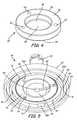
- FIG. 2is an exploded side view of pressure compensating device from FIG. 1 .
- FIG. 3is a top perspective view of the lower housing from FIG. 2 .
- FIG. 4is a top perspective view of the compensating disc from FIG. 2 .
- FIG. 5is a bottom perspective view of the upper housing from FIG. 2 .
- FIG. 6is a cross section of the pressure compensating device from FIG. 2 assembled.
- FIG. 1is a schematic view of IV therapy administration system 10 including pressure compensating device 12 in accordance with the present invention. Depicted in FIG. 1 are the components of IV therapy administration system 10 : pressure compensating device 12 , IV bag 14 , upper tubing 16 , lower tubing 18 , venipuncture site 20 , and patient 22 . Pressure compensating device 12 compensates for variations in the head pressure of IV solution in IV therapy administration system 10 .
- Pressure compensating device 12is located between IV bag 14 and venipuncture site 20 . Fluidly connecting pressure compensating device 12 to IV bag 14 is flexible upper tubing 16 . Similarly, flexible lower tubing 18 connects pressure compensating device 12 to venipuncture site 20 on patient 22 . Located along upper tubing 16 or lower tubing 18 , a flow control regulator, such as but not limited to a pinch valve or roller clamp, can be incorporated into IV therapy administration system 10 . Venipuncture site 20 provides direct access to patient's 22 circulatory system via a needle inserted into a peripheral vein. To administer the contents of IV bag 14 to patient 22 , IV bag 14 is hung above patient 22 with pressure compensating device 12 positioned between IV bag 14 and venipuncture site 20 .
- a flow control regulatorsuch as but not limited to a pinch valve or roller clamp
- IV therapy administration system 10uses gravity to pull an IV solution downwardly out of IV bag 14 through upper tubing 16 to pressure compensating device 12 through lower tubing 18 and into venipuncture site 20 on patient 22 .
- Pressure compensating device 12uses fluid head pressure exerted on IV solution in IV bag 14 to overcome the venous back pressure of patient 22 . As IV therapy progresses, however, the volume of solution within IV bag 14 is reduced. The reduced volume changes head pressure in IV administration system 10 , thereby slowing the rate at which IV solution is delivered to venipuncture site 20 .
- Pressure compensating device 12is configured to compensate for such variations in fluid pressure and maintain a predetermined flow rate.
- FIG. 2is an exploded side view of pressure compensating device from FIG. 1 .
- Depicted in FIG. 2are the components of pressure compensating device 12 : lower housing 24 , upper housing 26 , compensating disc 28 , internal chamber 29 , inlet 30 , top surface 32 , outlet 34 , and bottom surface 36 .
- the components of pressure compensating device 12are assembled to compensate for changes in fluid pressure within IV administration system 10 .
- Pressure compensating device 12is constructed from lower housing 24 and upper housing 26 .
- Lower housing 24 and upper housing 26can be formed by injection molding of a suitable medical grade plastic material such as polypropylene. Just as the names indicate, lower housing 24 is located beneath and attached to upper housing 26 . In between upper housing 26 and lower housing 24 , is compensating disc 28 . Compensating disc 28 can be formed by compression molding of a suitable medical grade material elastomer, such as silicone rubber.
- Upper housing 26 and lower housing 24fit together to form internal chamber 29 above and below compensating disc 28 . Attached to upper housing 26 is inlet 30 . More specifically, inlet 30 extends at an approximately right angle from top surface 32 of upper housing 26 . In opposition to inlet 30 is outlet 34 attached to lower housing 24 . Outlet 30 extends at an approximately right angle from bottom surface 36 of lower housing 24 . So assembled, the components of pressure compensating device 12 function together to maintain the set flow rate despite changes in fluid pressure between inlet 30 and outlet 34 .
- IV solutionenters pressure compensating device 12 via inlet 30 on upper housing 26 .
- fluidencounters compensating disc 28 .
- a top surface of compensating disc 28is at essentially the same pressure as IV fluid within IV bag 14
- a bottom surface of compensating disc 28is at essentially the same pressure as venipuncture site 20 . If pressure exerted on the top surface of compensating disc 28 is reduced, compensating disc 28 will flex away from lower housing 24 effectively increasing the effective size of an outlet port on lower housing 24 . A larger outlet port increases the rate of fluid flow out of outlet 34 .
- FIG. 3is a top perspective view of lower housing 24 from FIG. 2 . Depicted in FIG. 3 are the components of lower housing 24 : outlet 34 , bottom surface 36 , top surface 38 , rim 40 , flange 42 , notches 43 , track 44 , sealing ring 45 , channel 46 , outlet port 48 , outlet port ring 49 , and land 50 . Lower housing 24 is configured to form a bottom portion of internal chamber 29 , which holds compensating disc 28 .
- Lower housing 24has a bottom surface 36 and an opposing top surface 38 . Extending downwardly from an approximate center of bottom surface 36 is outlet 34 . In the depicted embodiment, outlet 34 forms an approximately right angle with bottom surface 36 of lower housing 24 , and is sized to receive medical tubing, such as lower tubing 18 .
- the circumference of lower housing 24is defined by rim 40 , which protrudes upwardly from top surface 38 of lower housing 24 .
- flange 42Within rim 40 and also extending upwardly from top surface 38 is flange 42 .
- Flange 42includes upper portion 42 A, lower portion 42 B, and shoulder 42 C located between upper portion 42 A and lower portion 42 B. Although flange 42 is mostly continuous and annular, one or more cut-outs or notches 43 can extend into flange 42 .
- sealing ring 45is annular and continuous around top surface 38 of lower housing 24 .
- sealing ring 45has a height between approximately 0.005 and 0.015 inches (0.0127 and 0.0381 centimeters) and a width between approximately 0.015 and 0.025 inches (0.0381 and 0.0635 centimeters), although the invention is not so limited. Sealing ring 45 can assume any configuration capable of maintaining a proper seal with compensating disc 28 .
- sealing ring 45Located within sealing ring 45 is radial channel 46 extending from a location near sealing ring 45 to centrally located outlet port 48 .
- Outlet port 48leads fluid from channel 46 into outlet 34 and therefore, out of compensating device 12 .
- Also within sealing ring 45 and extending around outlet port 48is raised port ring 49 .
- Between port ring 49 and sealing ring 45is raised land 50 .
- Land 50is substantially annular and convex except for a small cut-out where channel 46 is connected to outlet port 48 to allow for fluid connection.
- Lower housing 24is the lowermost portion of compensating device 12 .
- Outlet 34is the location where fluid is discharged from flow rate regulator 12 , usually into lower tubing 18 for administration to patient 22 .
- Upwardly extending rim 40 , flange 42 , notches 43 A and 43 B, and track 44are all configured to couple with corresponding mating parts depending downwardly from upper housing 26 .
- fluid exiting upper housing 26arrives on a top surface of compensating disc 28 , which rests centrally on top surface 38 within flange 42 . More specifically, compensating disc 28 engages sealing ring 45 and land 50 of lower housing 24 . Sealing ring 45 functions to prevent fluid from leaking out of lower housing 24 and also secures compensating disc 28 onto lower housing 24 .
- Compensating disc 28engages or stretches across land 50 so that it is sufficiently taut to allow flexing or oscillation above outlet port 48 .
- fluidarrives at channel 46 of lower housing 24 . From channel 46 , fluid is directed inwards toward outlet port 48 .
- Outlet port 48is fluidly connected to outlet 34 where fluid is discharged from compensating device 12 . So assembled, lower housing 24 engages compensating disc 28 , which flexes in response to changes in fluid pressure.
- FIG. 4is a top perspective view of compensating disc 28 from FIG. 2 . Depicted in FIG. 4 are the components of compensating disc 28 : top surface 52 , bottom surface 54 , rim 56 , diaphragm 58 , flex point 59 , holes 60 , and through bore 62 . Diaphragm 58 flexes to compensate for a difference in fluid pressure between inlet 30 and outlet 34 .
- Compensating disc 28has top surface 52 and opposing bottom surface 54 .
- Thick annular rim 56extends around a circumference of compensating disc 28 .
- Extending across bottom surface 54 of annular rim 56is diaphragm 58 .
- Diaphragm 58attaches to an outer diameter of, and is integral with, rim 56 .
- Centrally located within diaphragm 58is flex point 59 .
- Two holes 60are shown extending into rim 56 , although more or less holes 60 are possible.
- One through bore 62is also shown extending all the way through rim 56 , although more or less bores 62 are possible.
- Holes 60are configured to precisely align disc 28 to mating upper housing 26 such that through bore 62 is precisely centered under flow channel outlet 82 B (shown in FIG. 5 ).
- compensating disc 28When assembled into compensating device 12 , compensating disc 28 is located in internal chamber 29 formed between upper housing 26 and lower housing 24 . So placed, at least a portion of top surface 52 contacts upper housing 26 . Similarly, at least a portion of bottom surface 54 contacts lower housing 24 . More specifically, bottom surface of diaphragm 58 contacts an outer diameter and top surface of land 50 on lower housing 24 . Bottom surface of diaphragm 58 stretches up and over land 50 so that diaphragm 58 is slightly taut. When diaphragm 58 is stretched over land 50 , flex point 59 is aligned over a central axis of outlet port 48 .
- Flex point 59 of diaphragm 58is configured to flex or deflect toward and away from port ring 49 in response to changes in fluid pressure.
- Holes 60mate with locator pins 74 projecting from upper housing 26 to align through bore 62 with flow channel outlet 82 B, located on upper housing 26 .
- Through bore 62then provides a fluid connection between upper housing 26 and lower housing 24 .
- the arrangement of compensating disc 28 with respect to upper housing 26is discussed further with reference to FIG. 5 .
- FIG. 5is a bottom perspective view of upper housing 26 from FIG. 2 .
- Depicted in FIG. 5are the components of upper housing 26 as seen from the bottom: inlet 30 , top surface 32 , outer lip 64 , inner lip 66 , track 68 , sealing ring 70 , bottom surface 72 , locator pins 74 , centering ribs 76 , tabs 78 , inlet port 80 , flow channel 82 , and puck 84 .
- Upper housing 26mates with lower housing 24 to create internal chamber 29 , which houses compensating disc 28 .
- Upper housing 26has inlet 30 extending from an approximate center of top surface 32 .
- Inlet 30extends outwardly and upwardly from top surface 32 of upper housing 26 at an angle of approximately 90 degrees.
- inlet 30is circular in cross-section and sized to be connectable to conventional medical tubing, such as upper tubing 16 .
- Inlet 30defines an inlet passage for receiving liquid that fluidly connects inlet port 80 to flow channel 82 .
- Facing in the opposite direction from top surface 32is bottom surface 72 .
- Extending downwardly from bottom surface 72are outer lip 64 and inner lip 66 . Both inner lip 66 and outer lip 64 are annular and continuous.
- Outer lip 64depends from the periphery of upper housing 26 , and inner lip 66 is located inside of outer lip 64 such that annular track 68 is created between outer lip 64 and inner lip 66 .
- annular sealing ring 70Located inside of inner lip 66 is annular sealing ring 70 , and located inside of sealing ring 70 are locator pins 74 , inlet port 80 , flow channel 82 and flow channel outlet port 82 B.
- two locator pins 74extend downward from bottom surface 72 to create a necessary alignment with holes 60 in disc 28 such that through bore 62 is aligned with flow channel outlet port 82 B.
- Sealing ring 70is similar in structure to sealing ring 45 described above in that it has a height between approximately 0.005 and 0.015 inches (0.0127 and 0.0381 centimeters) and a width between approximately 0.015 and 0.025 inches (0.0381 and 0.0635 centimeters), although the invention is not so limited. Sealing ring 70 can assume any configuration capable of maintaining a proper seal with compensating disc 28 .
- Flow channel 82extends from inlet port 80 along bottom surface of puck 84 and bottom surface 72 of upper housing 26 to fluidly connect inlet port 80 to flow channel outlet port 82 B.
- Ribs 76protrude centrally from inner lip 66 at regular intervals, as do tabs 78 , to aid in mating upper housing 26 to lower housing 24 .
- inner lip 66 of upper housing 26is configured to slide over flange 42 and encapsulate compensating disc 28 inside internal chamber 29 . More specifically, inner lip 66 of upper housing 26 rests on shoulder 42 C of lower housing 24 . Sealing ring 70 grips and thereby seals compensating disc 28 to bottom surface 72 of upper housing 26 to prevent leaks. To further secure compensating disc 28 into its predetermined location, locator pins 74 are received into holes 60 located on rim 56 , thereby placing through bore 62 in fluid communication with inlet port 80 .
- centering ribs 76center inner lip 66 of upper housing 26 with respect to an outer surface of flange 42 from lower housing 24 .
- Boss 78 Aengages notch 43 A and boss 78 B engages notch 43 B to ensure proper rotational alignment of middle housing 26 and lower housing 24 .
- Channel 82conducts fluid from inlet 30 to inlet port 80 .
- Puck 84is a convex protrusion extending centrally from bottom surface 72 around channel 82 . So configured, upper housing 26 forms a top portion of internal chamber 29 , which houses compensating disc 28 .
- FIG. 6is a cross section of compensating device 12 from FIG. 2 fully assembled for use in IV therapy administration system 10 .
- components of compensating device 12described in detail above: lower housing 24 , upper housing 26 , compensating disc 28 , inlet 30 , and outlet 34 .
- dimensions A-Nwhich can be used to manufacture the depicted embodiment of compensating device 12 .
- lower housing 24has approximately the following dimensions.
- Land 50has diameter A between about 0.450 inches (1.14 cm) and about 0.460 inches (1.17 cm), more preferably between about 0.454 inches (1.15 cm) and about 0.457 inches (1.16 cm).
- Land 50has height B between about 0.050 inches (0.127 cm) and about 0.060 inches (0.152 cm), more preferably between about 0.053 inches (0.135 cm) and about 0.057 inches (0.145 cm).
- the raised portion of land 50has radius C between about 0.010 inches (0.025 cm) and about 0.030 inches (0.077 cm), more preferably between about 0.020 inches (0.051 cm) and about 0.025 inches (0.064 cm).
- Outlet port ring 49has height E between about 0.047 inches (0.120 cm) to about 0.057 inches (0.145 cm), more preferably between about 0.049 inches (0.124 cm) and 0.054 inches (0.137 cm).
- Flange 42has inner diameter F between about 0.875 inches (2.22 cm) and about 0.885 inches (2.25 cm), more preferably between about 0.879 inches (2.23 cm) and about 0.882 inches (2.24 cm).
- compensating disc 28has approximately the following dimensions.
- Rim 56has height G between about 0.134 inches (0.340 cm) and about 0.144 inches (0.366 cm), more preferably between about 0.136 inches (0.346 cm) and about 0.142 inches (0.361 cm).
- Rim 56has outer diameter H between about 0.867 inches (2.20 cm) and about 0.877 inches (2.23 cm), more preferably between about 0.870 inches (2.21 cm) and about 0.875 inches (2.22 cm).
- Rim 56has inner diameter I between about 0.505 inches (1.28 cm) and about 0.520 inches (1.32 cm), more preferably between about 0.510 inches (1.30 cm) and about 0.515 inches (1.31 cm).
- Diaphragm 58has a thickness J between about 0.008 inches (0.020 cm) and about 0.020 inches (0.051 cm), more preferably between about 0.010 inches (0.025 cm) and about 0.016 inches (0.041 cm).
- Compensating disc 28can be fabricated by compression molding using a silicone material having approximately the following material characteristics: durometer (Shore A) 50 and above (ASTM D-2240), tensile strength 1100 to 1200 (ASTM D-412), elongation percent 200-300 (ASTM D-412), modulus at 100 percent 60 to 70 (ASTM D-624), tear strength 50 to 60 (ASTM D-624), and Bayshore resilience 60 and above (ASTM D-624).
- upper housing 26has approximately the following dimensions.
- Puck 84has height L between about 0.055 inches (0.140 cm) and about 0.065 inches (0.165 cm), more preferably between about 0.057 inches (0.145 cm) and about 0.061 inches (0.155 cm).
- Distance M between puck 84 and land 50is between about 0.005 inches (0.013 cm) and about 0.040 inches (0.102 cm), more preferably between about 0.010 inches (0.025 cm) and about 0.030 inches (0.076 cm).
- rim 56 height G relative to land 50 height Bhas a ratio between about 2 and about 3.
- Rim 56 inner diameter I relative to land 50 outer diameter Ahas a ratio between about 1.10 and about 1.15.
- Land 50 height B relative to port ring 49 height Ehas a ratio between about 1.0 and about 1.1.
- a distance between about 0.015 inches (0.038 cm) and about 0.040 inches (0.102 cm)should span between a top surface of land 50 and a bottom surface of puck 84 .
- rim 56 height G and inner diameter Iare dimensioned relative to the distance between top surface 38 of lower housing 24 and puck 84 of upper housing 26 .
- internal chamber 29must have sufficient depth to allow diaphragm 58 to flex freely. Construction of pressure compensating device 12 with the above recited ratios has been shown to optimize the effectiveness of pressure compensation.
- Compensating device 12is designed to compensate for changes in pressure between fluid entering inlet 30 and fluid exiting outlet 34 .
- gravitypulls IV solution out of IV bag 14 through upper tubing 16 and into inlet 30 .
- fluidpasses through inlet port 80 , fills the upper chamber and is routed radially via flow channel 82 to flow channel outlet port 82 B.
- Fluidthen flows through bore 62 into flow channel 46 , under bottom surface 54 of diaphragm 58 filling the lower chamber 29 . Fluid then passes through outlet port 48 and through outlet 34 .
- fluid pressureis exerted upon top and bottom surfaces of diaphragm 58 such that flex point 59 flexes at some frequency and amplitude.
- flex point 59flexes towards or away from outlet port 48 . Fluid flows through outlet port 48 where gravity pulls the fluid out of outlet 34 through lower tubing 18 and into venipuncutre site 20 on patient 22 .
- the top surface of diaphragm 58is at essentially the same pressure as IV bag 14
- the bottom surface of diaphragm 58is at essentially the same pressure as venipuncture site 20 .
- a decrease in head pressurereduces the amount of pressure exerted on top surface of diaphragm 58 relative to pressure exerted on bottom surface of diaphragm 58 , thereby forcing diaphragm 58 of compensating disc 28 to either increase or decrease the frequency and amplitude at which diaphragm 58 oscillates towards or away from outlet 48 of lower housing 24 .
- diaphragm 58moves away from outlet ring 49 it effectively increases space for fluid to enter outlet port 48 , thereby increasing rate of fluid flow.
- Compensating device 12uses compensating disc 28 to maintain the pressure differential between the inlet 30 and outlet 34 .
- a top surface of land 50is preferably parallel to a bottom surface of puck 84 .
- Top surface 38 of lower housing 24is also preferably parallel to bottom surface 72 of upper housing 26 .
- a top surface of outlet ring 49is preferably parallel to bottom surface 54 of diaphragm 58 when diaphragm 58 is not deflected by a pressure differential.
- Such parallelismalong with the dimensions described above, ensure that diaphragm 58 is stretched equally across land 50 and therefore, flex point 59 is aligned over a central axis of outlet port 48 .
Landscapes
- Health & Medical Sciences (AREA)
- Hematology (AREA)
- General Health & Medical Sciences (AREA)
- Vascular Medicine (AREA)
- Engineering & Computer Science (AREA)
- Anesthesiology (AREA)
- Biomedical Technology (AREA)
- Veterinary Medicine (AREA)
- Life Sciences & Earth Sciences (AREA)
- Heart & Thoracic Surgery (AREA)
- Animal Behavior & Ethology (AREA)
- Public Health (AREA)
- Physics & Mathematics (AREA)
- Fluid Mechanics (AREA)
- Infusion, Injection, And Reservoir Apparatuses (AREA)
- Measuring Fluid Pressure (AREA)
Abstract
Description
Claims (16)
Priority Applications (2)
| Application Number | Priority Date | Filing Date | Title |
|---|---|---|---|
| US12/322,476US8480634B2 (en) | 2009-02-03 | 2009-02-03 | Pressure compensating device |
| PCT/US2010/000200WO2010090708A2 (en) | 2009-02-03 | 2010-01-26 | Pressure compensating device |
Applications Claiming Priority (1)
| Application Number | Priority Date | Filing Date | Title |
|---|---|---|---|
| US12/322,476US8480634B2 (en) | 2009-02-03 | 2009-02-03 | Pressure compensating device |
Publications (2)
| Publication Number | Publication Date |
|---|---|
| US20100198154A1 US20100198154A1 (en) | 2010-08-05 |
| US8480634B2true US8480634B2 (en) | 2013-07-09 |
Family
ID=42398301
Family Applications (1)
| Application Number | Title | Priority Date | Filing Date |
|---|---|---|---|
| US12/322,476Active - Reinstated2029-04-20US8480634B2 (en) | 2009-02-03 | 2009-02-03 | Pressure compensating device |
Country Status (2)
| Country | Link |
|---|---|
| US (1) | US8480634B2 (en) |
| WO (1) | WO2010090708A2 (en) |
Families Citing this family (1)
| Publication number | Priority date | Publication date | Assignee | Title |
|---|---|---|---|---|
| DE102013212325A1 (en)* | 2013-06-26 | 2014-12-31 | B. Braun Melsungen Ag | Adjustment device for a flow regulator |
Citations (60)
| Publication number | Priority date | Publication date | Assignee | Title |
|---|---|---|---|---|
| US3207641A (en) | 1960-10-11 | 1965-09-21 | Exxon Research Engineering Co | Process for coating a reinforcing element with a polyfunctional monomer, applying a resinifiable mixture and laminating |
| US3532126A (en) | 1967-11-01 | 1970-10-06 | Gen Electric | Ganged variable fluidic resistor device |
| US3620500A (en) | 1970-02-04 | 1971-11-16 | Deseret Pharma | Variable aperture fluid flow control apparatus |
| US3656138A (en) | 1970-03-18 | 1972-04-11 | Interscience Corp | Infusion monitoring device |
| US3785378A (en) | 1972-04-06 | 1974-01-15 | C Stewart | Flow control valve for intravenous fluids |
| US3806086A (en) | 1973-03-15 | 1974-04-23 | Nosco Plastics | Automatic shut-off valve for administration of sterile fluids |
| US3841354A (en) | 1973-05-22 | 1974-10-15 | R Mcdonnell | Flow regulating device |
| US3868973A (en) | 1973-03-16 | 1975-03-04 | Howard R Bierman | Flow controlling or metering device |
| US3957082A (en) | 1974-09-26 | 1976-05-18 | Arbrook, Inc. | Six-way stopcock |
| US4079737A (en) | 1975-01-14 | 1978-03-21 | Med-Pak Corporation | Control valve for infusion system |
| US4146055A (en) | 1977-03-21 | 1979-03-27 | Ryder International Corporation | Valve structure |
| US4300552A (en) | 1978-09-01 | 1981-11-17 | Imed Corporation | Apparatus for controlling the flow of intravenous fluid to a patient |
| US4361147A (en) | 1979-01-22 | 1982-11-30 | Master Medical Corporation | Flow control device for administration of intravenous fluids |
| US4384680A (en) | 1976-10-26 | 1983-05-24 | Hydro-Plan Engineering Ltd. | Fluid flow regulator unit |
| US4415003A (en)* | 1981-02-18 | 1983-11-15 | Nypro Inc. | Control of fluid flow using a flexible disc |
| US4474574A (en) | 1982-01-11 | 1984-10-02 | Alza Corporation | Formulation dispenser for use with a parenteral delivery system |
| US4504263A (en) | 1982-12-22 | 1985-03-12 | Valleylab, Inc. | Flow rate monitor with optical sensing chamber |
| US4515588A (en) | 1983-05-16 | 1985-05-07 | Health Care Concepts, Inc. | I.V. flow regulator |
| US4533348A (en) | 1983-07-29 | 1985-08-06 | Alza Corporation | In-line drug dispenser for use in intravenous therapy |
| US4581014A (en) | 1984-04-03 | 1986-04-08 | Ivac Corporation | Fluid infusion system |
| US4589872A (en) | 1985-02-19 | 1986-05-20 | Bellin Matthew E | Quick action flow regulator for medical apparatus |
| US4593717A (en) | 1983-08-12 | 1986-06-10 | Levasseur Joseph E | Valve |
| US4604093A (en) | 1984-06-12 | 1986-08-05 | I-Flow Corporation | Apparatus and method for administering multiple fluid infusions |
| US4613325A (en) | 1982-07-19 | 1986-09-23 | Abrams Lawrence M | Flow rate sensing device |
| US4634434A (en) | 1985-02-19 | 1987-01-06 | Biomedical Dynamics Corporation | Apparatus for regulating the flow of fluid in medical apparatus |
| US4722732A (en) | 1986-10-20 | 1988-02-02 | James Martin | Intravenous fluid supply system |
| US4738665A (en) | 1985-09-27 | 1988-04-19 | Hall Hill Co. | Method and apparatus for controlling flow rate of fluid |
| US4769012A (en) | 1984-11-02 | 1988-09-06 | Codan Medizinische Gerate Gmbh & Co. Kg | Gravity infusion and transfusion flow regulating device |
| US4789000A (en) | 1984-07-13 | 1988-12-06 | Aslanian Jerry L | Flow control device for administration |
| US4802506A (en) | 1984-07-13 | 1989-02-07 | Aslanian Jerry L | Flow control device for administration of intravenous fluids |
| US4807660A (en) | 1984-07-13 | 1989-02-28 | Aslanian Jerry L | Flow control device for administration of intravenous fluids |
| US4822344A (en) | 1986-12-05 | 1989-04-18 | Sta-Set Corp. | Apparatus for controlling fluid flow rate |
| US4874386A (en) | 1986-12-05 | 1989-10-17 | Sta-Set Corporation | Fluid dispensing device |
| US4917687A (en) | 1986-12-05 | 1990-04-17 | Sta-Set Corporation | Apparatus for controlling fluid flow rate |
| US4925451A (en) | 1988-04-18 | 1990-05-15 | Amendolia Pasquale J | I.V. flow control device |
| US4947856A (en) | 1988-10-26 | 1990-08-14 | Abbott Laboratories | Fluid pressure monitoring and flow control apparatus |
| US5005604A (en) | 1984-07-13 | 1991-04-09 | Aslanian Jerry L | Flow control device for administration of intravenous fluids |
| US5009251A (en) | 1988-11-15 | 1991-04-23 | Baxter International, Inc. | Fluid flow control |
| US5014750A (en) | 1988-03-14 | 1991-05-14 | Baxter International Inc. | Systems having fixed and variable flow rate control mechanisms |
| US5033714A (en) | 1988-03-14 | 1991-07-23 | Baxter International Inc. | Systems having fixed and variable flow rate control mechanisms |
| USD319506S (en) | 1989-05-17 | 1991-08-27 | Baxter International Inc. | I.V. flow regulator |
| US5113904A (en) | 1984-07-13 | 1992-05-19 | Aslanian Jerry L | Flow control device for administration of intravenous fluids |
| US5176360A (en) | 1988-03-14 | 1993-01-05 | Baxter International Inc. | Infusor having fixed and variable flow rate control mechanisms |
| US5190527A (en) | 1989-09-25 | 1993-03-02 | Baxter International Inc. | Intravenous metering device |
| US5234413A (en) | 1989-07-25 | 1993-08-10 | Wonder Terry M | Infusion rate regulator device |
| US5240035A (en) | 1991-03-04 | 1993-08-31 | Jerry Aslanian | Pressure compensated flow control device for IV administration |
| US5241985A (en) | 1986-03-04 | 1993-09-07 | Deka Products Limited Partnership | Flow control valve system |
| US5346477A (en) | 1989-09-29 | 1994-09-13 | Harmac Medical Products, Inc. | Pressure gauge for regulating pressure in a disposable pressure cuff |
| US5413282A (en) | 1993-10-28 | 1995-05-09 | James Hardie Irrigation, Inc. | Pressure compensating emitter with shut down flush |
| US5445622A (en) | 1994-12-20 | 1995-08-29 | Brown; Eric W. | Flow switch device for medical applications |
| US5499968A (en) | 1990-03-08 | 1996-03-19 | Macnaught Pty Limited | Flow controllers for fluid infusion sets |
| US5520661A (en)* | 1994-07-25 | 1996-05-28 | Baxter International Inc. | Fluid flow regulator |
| US5730730A (en) | 1995-09-29 | 1998-03-24 | Darling, Jr.; Phillip H. | Liquid flow rate control device |
| US6213986B1 (en) | 1995-09-29 | 2001-04-10 | Appro Healthcare, Inc. | Liquid flow rate control device |
| US6290681B1 (en) | 1994-12-20 | 2001-09-18 | Remote Medical Corporation | Flow monitoring device for medical application |
| US20030135164A1 (en)* | 2002-01-16 | 2003-07-17 | Simon Michael G. | Pressure compensating IV flow control regulator |
| US6709417B1 (en) | 1995-06-07 | 2004-03-23 | Deka Products Limited Partnership | Valve for intravenous-line flow-control system |
| US20050065480A1 (en) | 2001-11-29 | 2005-03-24 | Lee Sang Bin | Device for regulating flow rate of intravenous medical solution during injection |
| US20050131335A1 (en) | 2003-12-11 | 2005-06-16 | Gambro Lundia Ab. | Switching device and apparatus for controlling flow of a fluid |
| US20050197631A1 (en) | 2004-03-02 | 2005-09-08 | Schinazi Robert G. | Flow restrictor device for a medical apparatus |
- 2009
- 2009-02-03USUS12/322,476patent/US8480634B2/enactiveActive - Reinstated
- 2010
- 2010-01-26WOPCT/US2010/000200patent/WO2010090708A2/enactiveApplication Filing
Patent Citations (60)
| Publication number | Priority date | Publication date | Assignee | Title |
|---|---|---|---|---|
| US3207641A (en) | 1960-10-11 | 1965-09-21 | Exxon Research Engineering Co | Process for coating a reinforcing element with a polyfunctional monomer, applying a resinifiable mixture and laminating |
| US3532126A (en) | 1967-11-01 | 1970-10-06 | Gen Electric | Ganged variable fluidic resistor device |
| US3620500A (en) | 1970-02-04 | 1971-11-16 | Deseret Pharma | Variable aperture fluid flow control apparatus |
| US3656138A (en) | 1970-03-18 | 1972-04-11 | Interscience Corp | Infusion monitoring device |
| US3785378A (en) | 1972-04-06 | 1974-01-15 | C Stewart | Flow control valve for intravenous fluids |
| US3806086A (en) | 1973-03-15 | 1974-04-23 | Nosco Plastics | Automatic shut-off valve for administration of sterile fluids |
| US3868973A (en) | 1973-03-16 | 1975-03-04 | Howard R Bierman | Flow controlling or metering device |
| US3841354A (en) | 1973-05-22 | 1974-10-15 | R Mcdonnell | Flow regulating device |
| US3957082A (en) | 1974-09-26 | 1976-05-18 | Arbrook, Inc. | Six-way stopcock |
| US4079737A (en) | 1975-01-14 | 1978-03-21 | Med-Pak Corporation | Control valve for infusion system |
| US4384680A (en) | 1976-10-26 | 1983-05-24 | Hydro-Plan Engineering Ltd. | Fluid flow regulator unit |
| US4146055A (en) | 1977-03-21 | 1979-03-27 | Ryder International Corporation | Valve structure |
| US4300552A (en) | 1978-09-01 | 1981-11-17 | Imed Corporation | Apparatus for controlling the flow of intravenous fluid to a patient |
| US4361147A (en) | 1979-01-22 | 1982-11-30 | Master Medical Corporation | Flow control device for administration of intravenous fluids |
| US4415003A (en)* | 1981-02-18 | 1983-11-15 | Nypro Inc. | Control of fluid flow using a flexible disc |
| US4474574A (en) | 1982-01-11 | 1984-10-02 | Alza Corporation | Formulation dispenser for use with a parenteral delivery system |
| US4613325A (en) | 1982-07-19 | 1986-09-23 | Abrams Lawrence M | Flow rate sensing device |
| US4504263A (en) | 1982-12-22 | 1985-03-12 | Valleylab, Inc. | Flow rate monitor with optical sensing chamber |
| US4515588A (en) | 1983-05-16 | 1985-05-07 | Health Care Concepts, Inc. | I.V. flow regulator |
| US4533348A (en) | 1983-07-29 | 1985-08-06 | Alza Corporation | In-line drug dispenser for use in intravenous therapy |
| US4593717A (en) | 1983-08-12 | 1986-06-10 | Levasseur Joseph E | Valve |
| US4581014A (en) | 1984-04-03 | 1986-04-08 | Ivac Corporation | Fluid infusion system |
| US4604093A (en) | 1984-06-12 | 1986-08-05 | I-Flow Corporation | Apparatus and method for administering multiple fluid infusions |
| US4807660A (en) | 1984-07-13 | 1989-02-28 | Aslanian Jerry L | Flow control device for administration of intravenous fluids |
| US4802506A (en) | 1984-07-13 | 1989-02-07 | Aslanian Jerry L | Flow control device for administration of intravenous fluids |
| US5005604A (en) | 1984-07-13 | 1991-04-09 | Aslanian Jerry L | Flow control device for administration of intravenous fluids |
| US5113904A (en) | 1984-07-13 | 1992-05-19 | Aslanian Jerry L | Flow control device for administration of intravenous fluids |
| US4789000A (en) | 1984-07-13 | 1988-12-06 | Aslanian Jerry L | Flow control device for administration |
| US4769012A (en) | 1984-11-02 | 1988-09-06 | Codan Medizinische Gerate Gmbh & Co. Kg | Gravity infusion and transfusion flow regulating device |
| US4589872A (en) | 1985-02-19 | 1986-05-20 | Bellin Matthew E | Quick action flow regulator for medical apparatus |
| US4634434A (en) | 1985-02-19 | 1987-01-06 | Biomedical Dynamics Corporation | Apparatus for regulating the flow of fluid in medical apparatus |
| US4738665A (en) | 1985-09-27 | 1988-04-19 | Hall Hill Co. | Method and apparatus for controlling flow rate of fluid |
| US5241985A (en) | 1986-03-04 | 1993-09-07 | Deka Products Limited Partnership | Flow control valve system |
| US4722732A (en) | 1986-10-20 | 1988-02-02 | James Martin | Intravenous fluid supply system |
| US4822344A (en) | 1986-12-05 | 1989-04-18 | Sta-Set Corp. | Apparatus for controlling fluid flow rate |
| US4874386A (en) | 1986-12-05 | 1989-10-17 | Sta-Set Corporation | Fluid dispensing device |
| US4917687A (en) | 1986-12-05 | 1990-04-17 | Sta-Set Corporation | Apparatus for controlling fluid flow rate |
| US5176360A (en) | 1988-03-14 | 1993-01-05 | Baxter International Inc. | Infusor having fixed and variable flow rate control mechanisms |
| US5033714A (en) | 1988-03-14 | 1991-07-23 | Baxter International Inc. | Systems having fixed and variable flow rate control mechanisms |
| US5014750A (en) | 1988-03-14 | 1991-05-14 | Baxter International Inc. | Systems having fixed and variable flow rate control mechanisms |
| US4925451A (en) | 1988-04-18 | 1990-05-15 | Amendolia Pasquale J | I.V. flow control device |
| US4947856A (en) | 1988-10-26 | 1990-08-14 | Abbott Laboratories | Fluid pressure monitoring and flow control apparatus |
| US5009251A (en) | 1988-11-15 | 1991-04-23 | Baxter International, Inc. | Fluid flow control |
| USD319506S (en) | 1989-05-17 | 1991-08-27 | Baxter International Inc. | I.V. flow regulator |
| US5234413A (en) | 1989-07-25 | 1993-08-10 | Wonder Terry M | Infusion rate regulator device |
| US5190527A (en) | 1989-09-25 | 1993-03-02 | Baxter International Inc. | Intravenous metering device |
| US5346477A (en) | 1989-09-29 | 1994-09-13 | Harmac Medical Products, Inc. | Pressure gauge for regulating pressure in a disposable pressure cuff |
| US5499968A (en) | 1990-03-08 | 1996-03-19 | Macnaught Pty Limited | Flow controllers for fluid infusion sets |
| US5240035A (en) | 1991-03-04 | 1993-08-31 | Jerry Aslanian | Pressure compensated flow control device for IV administration |
| US5413282A (en) | 1993-10-28 | 1995-05-09 | James Hardie Irrigation, Inc. | Pressure compensating emitter with shut down flush |
| US5520661A (en)* | 1994-07-25 | 1996-05-28 | Baxter International Inc. | Fluid flow regulator |
| US5445622A (en) | 1994-12-20 | 1995-08-29 | Brown; Eric W. | Flow switch device for medical applications |
| US6290681B1 (en) | 1994-12-20 | 2001-09-18 | Remote Medical Corporation | Flow monitoring device for medical application |
| US6709417B1 (en) | 1995-06-07 | 2004-03-23 | Deka Products Limited Partnership | Valve for intravenous-line flow-control system |
| US5730730A (en) | 1995-09-29 | 1998-03-24 | Darling, Jr.; Phillip H. | Liquid flow rate control device |
| US6213986B1 (en) | 1995-09-29 | 2001-04-10 | Appro Healthcare, Inc. | Liquid flow rate control device |
| US20050065480A1 (en) | 2001-11-29 | 2005-03-24 | Lee Sang Bin | Device for regulating flow rate of intravenous medical solution during injection |
| US20030135164A1 (en)* | 2002-01-16 | 2003-07-17 | Simon Michael G. | Pressure compensating IV flow control regulator |
| US20050131335A1 (en) | 2003-12-11 | 2005-06-16 | Gambro Lundia Ab. | Switching device and apparatus for controlling flow of a fluid |
| US20050197631A1 (en) | 2004-03-02 | 2005-09-08 | Schinazi Robert G. | Flow restrictor device for a medical apparatus |
Non-Patent Citations (2)
| Title |
|---|
| 3M Health Care brochure, "3M IV Flow Regulator Sets" (1993), 4 pages. |
| PCT International Search Report and the Written Opinion of the International Searching Authority, Sep. 27, 2010, 14 pages. |
Also Published As
| Publication number | Publication date |
|---|---|
| US20100198154A1 (en) | 2010-08-05 |
| WO2010090708A2 (en) | 2010-08-12 |
| WO2010090708A3 (en) | 2010-12-02 |
Similar Documents
| Publication | Publication Date | Title |
|---|---|---|
| US7361165B2 (en) | Pressure compensating IV flow control regulator | |
| US5147333A (en) | Needleless injection port with automatic backcheck valve | |
| US5305795A (en) | Nonreturn valve, in particular for medical infusion appliances | |
| US4141379A (en) | Check valve | |
| US8057437B2 (en) | Radially sealing vavle for an infusion set | |
| US5025829A (en) | Parenteral check valve | |
| CA1152823A (en) | Implantable drug infusion regulator | |
| US20220313977A1 (en) | Priming apparatus for a drip chamber of a fluid infusion system | |
| US9901676B2 (en) | Bidirectional valve with improved threshold pressure accuracy | |
| EP0247824A2 (en) | Valve for medication infusion system | |
| US20100152680A1 (en) | One-way valve, especially low pressure check valve for use in the medical technique | |
| EP3019214B1 (en) | Check valve system | |
| AU2003205156A1 (en) | Pressure compensating IV flow control regulator | |
| US9052025B2 (en) | Bidirectional duckbill valve apparatus and a method for its use | |
| US6932110B2 (en) | Unidirectional valve appliance | |
| US10543350B2 (en) | Port septum with integral valve | |
| US8480634B2 (en) | Pressure compensating device | |
| EP2945689B1 (en) | Anti free flow valve | |
| US8556869B2 (en) | IV flow rate regulator | |
| US20150231385A1 (en) | Low opening pressure anti-siphon check valve | |
| WO2003024519A1 (en) | Anti free-flow valve | |
| CN221601046U (en) | Infusion connector | |
| CN104587569B (en) | A kind of Novel bubble-prevention infusion device | |
| US20230022342A1 (en) | Coupler device for valve assembly for use with medical infusion device | |
| CN113289084A (en) | Backflow prevention device for infusion apparatus and drainage bag |
Legal Events
| Date | Code | Title | Description |
|---|---|---|---|
| FEPP | Fee payment procedure | Free format text:PAYOR NUMBER ASSIGNED (ORIGINAL EVENT CODE: ASPN); ENTITY STATUS OF PATENT OWNER: MICROENTITY | |
| STCF | Information on status: patent grant | Free format text:PATENTED CASE | |
| FPAY | Fee payment | Year of fee payment:4 | |
| FEPP | Fee payment procedure | Free format text:MAINTENANCE FEE REMINDER MAILED (ORIGINAL EVENT CODE: REM.); ENTITY STATUS OF PATENT OWNER: SMALL ENTITY | |
| LAPS | Lapse for failure to pay maintenance fees | Free format text:PATENT EXPIRED FOR FAILURE TO PAY MAINTENANCE FEES (ORIGINAL EVENT CODE: EXP.); ENTITY STATUS OF PATENT OWNER: SMALL ENTITY | |
| STCH | Information on status: patent discontinuation | Free format text:PATENT EXPIRED DUE TO NONPAYMENT OF MAINTENANCE FEES UNDER 37 CFR 1.362 | |
| FP | Lapsed due to failure to pay maintenance fee | Effective date:20210709 | |
| PRDP | Patent reinstated due to the acceptance of a late maintenance fee | Effective date:20211022 | |
| FEPP | Fee payment procedure | Free format text:PETITION RELATED TO MAINTENANCE FEES FILED (ORIGINAL EVENT CODE: PMFP); ENTITY STATUS OF PATENT OWNER: MICROENTITY Free format text:PETITION RELATED TO MAINTENANCE FEES GRANTED (ORIGINAL EVENT CODE: PMFG); ENTITY STATUS OF PATENT OWNER: MICROENTITY Free format text:ENTITY STATUS SET TO MICRO (ORIGINAL EVENT CODE: MICR); ENTITY STATUS OF PATENT OWNER: MICROENTITY Free format text:SURCHARGE, PETITION TO ACCEPT PYMT AFTER EXP, UNINTENTIONAL (ORIGINAL EVENT CODE: M3558); ENTITY STATUS OF PATENT OWNER: MICROENTITY | |
| MAFP | Maintenance fee payment | Free format text:PAYMENT OF MAINTENANCE FEE, 8TH YEAR, MICRO ENTITY (ORIGINAL EVENT CODE: M3552); ENTITY STATUS OF PATENT OWNER: MICROENTITY Year of fee payment:8 | |
| STCF | Information on status: patent grant | Free format text:PATENTED CASE | |
| FEPP | Fee payment procedure | Free format text:MAINTENANCE FEE REMINDER MAILED (ORIGINAL EVENT CODE: REM.); ENTITY STATUS OF PATENT OWNER: MICROENTITY | |
| FEPP | Fee payment procedure | Free format text:SURCHARGE FOR LATE PAYMENT, MICRO ENTITY (ORIGINAL EVENT CODE: M3556); ENTITY STATUS OF PATENT OWNER: MICROENTITY | |
| MAFP | Maintenance fee payment | Free format text:PAYMENT OF MAINTENANCE FEE, 12TH YEAR, MICRO ENTITY (ORIGINAL EVENT CODE: M3553); ENTITY STATUS OF PATENT OWNER: MICROENTITY Year of fee payment:12 |