US8480406B2 - Interface device and method for interfacing instruments to medical procedure simulation systems - Google Patents
Interface device and method for interfacing instruments to medical procedure simulation systemsDownload PDFInfo
- Publication number
- US8480406B2 US8480406B2US11/204,646US20464605AUS8480406B2US 8480406 B2US8480406 B2US 8480406B2US 20464605 AUS20464605 AUS 20464605AUS 8480406 B2US8480406 B2US 8480406B2
- Authority
- US
- United States
- Prior art keywords
- capture mechanism
- insertion device
- interface device
- instrument
- capture
- Prior art date
- Legal status (The legal status is an assumption and is not a legal conclusion. Google has not performed a legal analysis and makes no representation as to the accuracy of the status listed.)
- Expired - Fee Related, expires
Links
Images


Classifications
- G—PHYSICS
- G09—EDUCATION; CRYPTOGRAPHY; DISPLAY; ADVERTISING; SEALS
- G09B—EDUCATIONAL OR DEMONSTRATION APPLIANCES; APPLIANCES FOR TEACHING, OR COMMUNICATING WITH, THE BLIND, DEAF OR MUTE; MODELS; PLANETARIA; GLOBES; MAPS; DIAGRAMS
- G09B23/00—Models for scientific, medical, or mathematical purposes, e.g. full-sized devices for demonstration purposes
- G09B23/28—Models for scientific, medical, or mathematical purposes, e.g. full-sized devices for demonstration purposes for medicine
- G09B23/285—Models for scientific, medical, or mathematical purposes, e.g. full-sized devices for demonstration purposes for medicine for injections, endoscopy, bronchoscopy, sigmoidscopy, insertion of contraceptive devices or enemas
Definitions
- the present inventionpertains to computerized simulation systems, generally of the types disclosed in: International Publication Number WO 96/28800, published Sep. 19, 1996 and entitled “Computer Based Medical Procedure Simulation System”; and the above-mentioned patent applications.
- the disclosure of the above-referenced international publicationis incorporated herein by reference in its entirety.
- the present inventionpertains to an interface device for a computerized medical procedure simulation system, the interface device including peripherals in the form of mock or actual medical instruments for use by a medical practitioner in performing various steps of a medical procedure in order to provide an enhanced realistic simulation of that procedure.
- minimally invasive medical proceduressuch as endoscopic or interventional radiological procedures
- endoscopic or interventional radiological proceduresmay be utilized by physicians to accomplish tasks that would otherwise require a patient to undergo open surgery.
- an angioplasty-balloon proceduremay be utilized by physicians to open and eliminate blockages in a blood vessel
- endoscopic proceduresmay be utilized by physicians to view and/or perform medical procedures on a bodily region of interest.
- Performance of minimally invasive medical proceduresrequires great skill to avoid complications that may cause serious injury to a patient and/or require the patient to undergo open surgery.
- the physicianis required to navigate a guidewire, catheter and sheath through an arterial network to a blockage point and inflate a balloon to eliminate the blockage, while avoiding a number of possible complications, such as rupturing an artery wall or dissecting the wall of the artery.
- physiciansneed to acquire the necessary skill levels and experience to perform minimally invasive medical procedures in order to ensure successful performance of these types of procedures on patients.
- a proceduremay usually only be performed once on a particular live patient and typically requires the presence of a skilled physician to supervise and oversee the procedure to avoid serious injury to the patient.
- training physicians or other medical professionals in minimally invasive surgical procedures on live patientsrequires the use of proper facilities and equipment (e.g., hospital facilities and equipment), thereby incurring substantial costs and limiting procedure practice to a particular time and location.
- the quantity of physicians that may practice or perform minimally invasive surgical proceduresis severely restricted, thereby limiting the quantity of physicians that may acquire sufficient experience to perform these types of procedures.
- U.S. Pat. No. 4,907,973discloses an expert system simulator for modeling realistic internal environments.
- the simulatormay be utilized to simulate an endoscopic procedure, whereby a mock endoscope is inserted and manipulated within a model.
- the modelincludes a mock bodily region of interest and a plurality of sensors to detect the position of the endoscope.
- a computerreceives signals from the sensors, and retrieves data from memory in accordance with those signals representing the view observed from the measured endoscope position during a real operation.
- the datais subsequently shown on a video display, whereby the displayed image is adjusted based on movement of the endoscope within the model.
- the simulatormay be used to simulate an angioplasty-balloon operation, whereby a mock catheter is inserted and manipulated within an internal arterial modeling device.
- the internal arterial modeling devicemay include mock arterial paths with sensors to track the progress of the inserted catheter within those paths.
- a computerretrieves and processes data from storage based on sensor data received from the internal sensors, and sends the processed data to a display that provides a visual display simulating a realistic environment (e.g., a view of the catheter within an arterial network).
- U.S. Pat. No. 4,642,055discloses a hemodynamic monitoring training system that allows medical professionals to obtain substantial experience in hemodynamic monitoring (e.g., placement of a catheter passed from a distant vein through the heart to the pulmonary vasculature for purposes of measuring intracardiac, pulmonary artery and wedge pressures to determine the type or extent of cardiopulmonary disease, to evaluate therapeutic measures and to monitor cardiac function).
- the systemincludes a trainer, computer, display, keyboard and mouse and simulates the catheterization process.
- a catheter having a balloon disposed at its distal endis inserted within a trainer manikin at a catheter insertion point.
- the balloonis typically inflated to assist the catheter tip through the heart, and may be inflated in the pulmonary artery to measure wedge pressure.
- the manikinincludes tubes representing veins extending internally from the insertion points, and a position sensor that measures advancement of the catheter tip past the sensor.
- the sensor dataenables the computer to determine the location of the catheter tip within a corresponding actual human body based on catheter manipulation within the trainer manikin.
- the computerreceives signals from the trainer and may provide on the display a simulated fluoroscope image showing simulated movement of the catheter through the heart and vasculature.
- the Hon and Saliterman systemssuffer from several disadvantages. Specifically, these systems utilize a physical model, thereby restricting training of a medical procedure to a particular bodily region or arterial paths defined by that model. Further, use of physical models degrades realism of the simulation and reduces the benefits of simulation training since the models usually do not contain substantially the same complex anatomy as an actual body, and permit a physician or other medical professional to become accustomed to performing a procedure on the same model anatomy. Performance of the procedure on another bodily region or through different arterial paths within the Hon and Saliterman systems typically requires a new model or substantial modifications to an existing model, thereby limiting flexibility of the systems and increasing system costs.
- the Saliterman systemdoes not provide computer-controlled force feedback to an instrument, thereby degrading realism of the simulation and reducing the benefits of simulation training.
- the Saliterman systemdoes not provide a computer simulated feel of forces applied to an instrument during an actual medical procedure.
- medical procedure simulation systemsemploy virtual reality technology to simulate performance of a medical procedure on a virtual bodily region of interest.
- Various types of interface devicesare typically utilized by these systems to enable a user to interact with the simulation system.
- the interface devicesmay provide force feedback to the user to simulate the forces encountered during an actual medical procedure.
- International Publication Number WO 95/02233discloses a medical procedure simulation system that utilizes virtual reality technology and force feedback to provide an accurate simulation of endoscopic medical procedures.
- the systemincludes a display device, sound device, graphics/image processing engine and storage module and programmable tactile/force reflecting mechanisms (e.g., disposed within an interface device) that provide force feedback to generate the “feel” of medical instruments and the interaction of the instruments with an anatomical simulation.
- Force feedbackis typically accomplished by a tactile/force reflecting mechanism via a four axis device that imparts forces and torques to a user's hands through a member representative of a medical instrument in response to manipulation of that member.
- the forces and torquesare applied to the user's hands based on the position of the member in relation to characteristics of a geometric model of an organ or virtual reality simulation of a medical procedure environment.
- the forces and torquesare typically generated by four servomotors that manipulate the member to provide a realistic feel during simulation.
- U.S. Pat. No. 5,623,582discloses a human/computer interface tool, typically for use with virtual reality simulation systems.
- the interface toolpreferably interfaces a substantially cylindrical object, such as a shaft of a surgeon's tool, to a simulation system computer such that the computer may generate signals to provide a virtual reality simulation with force feedback applied to the object.
- the interface toolincludes a gimbal mechanism, having two degrees of freedom, coupled to a support, and preferably three electromechanical transducers.
- the objectwhen engaged by the gimbal mechanism, may move with three degrees of freedom within a spherical coordinate space, whereby each transducer is associated with and senses a respective degree of freedom of motion of the object.
- a fourth transducermay be utilized by the interface tool to measure rotation of the object about an axis.
- the interface toolmay accommodate catheter insertion virtual reality systems, typically utilizing catheters having two degrees of freedom of motion, whereby the interface tool includes two transducers that are associated with and sense translation and rotation of a catheter, respectively.
- the transducers of the interface toolmay include actuators to impart a force upon the object to provide force feedback to a user.
- U.S. Pat. No. 5,821,920discloses an apparatus for interfacing an elongated flexible object with an electrical system including an object receiving portion and a rotation transducer.
- the rotation transducerdetermines rotational motion of an elongated object when the object is engaged with the object receiving portion and provides an electrochemical interface between the object and electrical system.
- the rotation transducermay further include an actuator and translational transducer to further provide a translation electrochemical interface between the object and electrical system.
- a tandem configurationmay be utilized for accommodating a device having an external shaft and an elongated flexible object. This configuration includes first and second object receiving portions that respectively accommodate the external shaft and elongated object.
- the first and second object receiving portionseach have an actuator and translation transducer, whereby a rotation transducer is rotatably coupled to the second object receiving portion.
- an object receiving portionmay be part of a gimbal apparatus.
- the transducers of the interface devicemay be implemented as input transducers for sensing motion, or output transducers for imparting forces onto the elongated object.
- U.S. Pat. No. 5,704,791discloses a virtual surgery system that enables simulation of a surgical procedure using image data of a patient and devices simulating the physical instruments a surgeon utilizes in an actual procedure.
- Image datacorresponding to a portion of an anatomy in a three dimensional data set, is stored in a memory of a computer, whereby a user input device is used to move through the image data, while the image data is viewed on a display.
- a virtual surgerymay be simulated based on the image data and manipulation of the input device.
- force feedbackmay be provided based on physical constraint models or edge and collision detection between a virtual tool and walls or edges of the image data.
- a surgical simulator user input device of the systemincludes a first virtual scope device attached to an end-portion of a hose that extends into and through a first virtual orifice and a box device.
- the first virtual orificeis attached at a top portion of the box device and accommodates the hose, while the box device includes an arrangement that handles and may further apply force feedback to the hose.
- a second instrumentis attached to a shaft that extends through a second virtual orifice defined in the first virtual scope device. Signals from the first virtual scope device, the second instrument and/or the first and second virtual orifices are provided to the computer to enable simulation of a surgical procedure.
- the virtual reality systems described abovesuffer from several disadvantages.
- the virtual reality systemsgenerally interface an elongated object without utilizing mechanisms to firmly grasp and capture the object, thereby degrading accuracy of object motion measurements.
- the virtual reality systemsgenerally accommodate a limited quantity of instruments within a nested instrument assembly, and do not permit exchange of instruments during a simulation, thereby reducing the benefits of simulation training since a medical professional may only gain experience for portions of a medical procedure utilizing the accommodated instruments.
- the virtual reality systemsgenerally accommodate either a limited quantity of independently inserted instruments, or a single nested instrument assembly, thereby limiting simulation training to specific procedures or portions of procedures utilizing the accommodated instruments (e.g., the systems generally do not accommodate plural independently inserted nested instrument assemblies, or plural independently inserted instruments where one of the instruments is a nested instrument assembly).
- the virtual reality systemstypically include fixed entry sites, thereby limiting the simulated procedure to a particular patient or entry site orientation.
- the Jacobus and Rosenberg (U.S. Pat. No. 5,623,582) systemsgenerally employ a plurality of actuators to provide force feedback to a single instrument, thereby increasing system complexity and cost.
- Another computer interface device for surgical simulation systemsincludes the Immersion PROBE produced by Immersion Corporation of Palo Alto, Calif.
- This interface deviceincludes a pen-like stylus supported on a light-weight mechanical linkage having six degrees of freedom, and reports the position and orientation of the stylus to a computer via a serial port interface.
- Sensorsare disposed at the linkage joints and send spatial coordinates (i.e., X, Y, Z) and orientation (i.e., roll, pitch, yaw) of the stylus to the computer.
- this interface devicedoes not resemble a common medical instrument and does not provide a manner to apply computer controlled force feedback to the interface device, thereby degrading realism of a simulation and reducing benefits of simulation training.
- Yet another object of the present inventionis to enhance realism within a medical procedure simulation system and to provide enhanced training of a medical procedure to practitioners by interfacing plural independently inserted instruments (e.g., that may include a nested instrument assembly) to the medical procedure simulation system via an interface device to enable realistic simulation of these instruments during a medical procedure.
- plural independently inserted instrumentse.g., that may include a nested instrument assembly
- Still another object of the present inventionis to enhance measurement of instrument motion within the interface device by firmly grasping and capturing an instrument via an interface device capture mechanism.
- a further object of the present inventionis to enhance realism within a medical procedure simulation system and to provide enhanced training of a medical procedure to medical practitioners by enabling a patient entry site to be manipulable to various orientations to permit realistic simulation of medical procedures on patients in different positions.
- an interface device and method for interfacing instruments to a medical procedure simulation systemserve to interface peripherals in the form of mock medical instruments to the medical procedure simulation system computer to enable simulation of medical procedures.
- the interface deviceincludes a housing having a mock bodily region of interest to facilitate insertion of a mock instrument, such as an endoscope tube, into the interface device via an orifice.
- the mock bodily region of interestmay be pivotable to simulate various patient orientations.
- the endoscope tubetraverses the orifice and a guide tube, and is subsequently engaged by a capture mechanism in order to measure rotational and translational motion of the endoscope tube.
- the capture mechanismis disposed at the proximal end of an inner tube, disposed in slidable relation within an outer tube, whereby the outer tube receives the endoscope tube from the guide tube.
- the inner tube distal endis attached to a trolley assembly having a rotational encoder to measure rotation of the inner tube, and hence, the endoscope tube, whereby the trolley assembly is coupled to a belt extending between and about first and second pulleys.
- a translational encoderis disposed proximate the first pulley to measure pulley rotation based on belt or trolley assembly motion, thereby providing an indication of endoscope tube translational motion.
- An actuatoris disposed proximate the second pulley to impede or enhance pulley rotation and belt or trolley assembly motion, thereby providing force feedback to the endoscope tube.
- the measured motionis provided to the computer system to reflect instrument motion on the display during the simulation.
- the interface devicemay be configured to measure instrument manipulation via a carrier assembly.
- the instrumentis inserted into the interface device, and extends to the carrier assembly.
- the carrier assemblyincludes a rotational encoder having a rotatable shaft that engages the instrument, via a set screw, to measure rotational motion.
- the carrier assemblyis attached to a belt that extends between and about first and second pulleys.
- a translational encoderis disposed proximate the first pulley to measure pulley rotation based on carrier assembly motion, thereby providing an indication of instrument translational motion.
- An actuatoris disposed proximate the second pulley to impede pulley rotation and belt or carrier assembly motion, thereby providing force feedback to the instrument.
- the interface devicemay further be configured to measure instrument manipulation via a carriage assembly.
- the instrumentis inserted into the interface device and extends through a bellows to the carriage assembly.
- the bellowsincludes a series of stabilizer openings to prevent buckling of the instrument.
- the carriage assemblyincludes a capture mechanism in the form of a collet assembly to grasp the instrument, and a rotational encoder to measure rotational motion of the instrument.
- a translational encoderis disposed toward the carriage assembly upper portion proximate an encoder strip to measure translational motion of the carriage assembly, and hence, the instrument translational motion.
- the carriage assemblyis connected to a belt extending between and about first and second pulleys.
- An actuatoris disposed proximate the first pulley to enhance or impede pulley rotation and carriage assembly motion, thereby providing force feedback to the instrument.
- This configurationmay further include a plurality of carriage assemblies to accommodate instrument assemblies having a plurality of nested instruments, whereby each carriage assembly includes a collet assembly of a particular dimension and grasps, measures manipulation of and provides force feedback to a particular instrument as described above.
- the interface devicemay include a plurality of the carriage assembly configurations described above arranged in parallel relation to simultaneously accommodate a plurality of independently inserted instruments.
- FIG. 1is a block diagram of a medical procedure simulation system including an interface device according to the present invention.
- FIG. 2is a schematic illustration of an exemplary display for the medical procedure simulation system of FIG. 1 .
- FIG. 3is a side view in elevation and partial section of the interface device of the medical procedure simulation system of FIG. 1 .
- FIG. 4is a side view in elevation and partial section of an instrument capture mechanism of the interface device of FIG. 3 .
- FIG. 5is a side view in elevation and partial section of the instrument capture mechanism of FIG. 4 in an expanded state to receive or release an endoscope navigation tube.
- FIG. 6is a side view in elevation and partial section of the instrument capture mechanism of FIG. 4 in a compressed state to engage an endoscope navigation tube.
- FIG. 7is a side view in elevation and partial section of a medical procedure simulation system interface device including a pivotable entry site according to the present invention.
- FIG. 8is a view in elevation of an interface device motion communication tube including an instrument capture mechanism according to the present invention.
- FIG. 9is a block diagram of the medical procedure simulation system of FIG. 1 having an interface device accommodating a wire, catheter and sheath according to the present invention.
- FIG. 10is a side view in elevation of an exemplary wire, catheter and sheath assembly.
- FIG. 11 ais a side view in elevation and partial section of an interface device for interfacing a catheter to a medical procedure simulation system according to the present invention.
- FIG. 11 bis a side view in elevation and partial section of a carrier of the interface device of FIG. 11 a.
- FIG. 12is an exploded view in perspective of an alternative embodiment of the interface device of FIG. 11 a according to the present invention.
- FIG. 13 ais an exploded perspective view of a carriage assembly of the interface device of FIG. 12 .
- FIG. 13 bis a perspective view of a collet of the carriage assembly of FIG. 13 a.
- FIGS. 14 a - 14 dare side views in elevation and partial section of the carriage assembly of the interface device of FIG. 12 illustrating operation of an instrument capture and quick-release mechanism.
- FIG. 15is an exploded view in perspective of an alternative embodiment of the interface device of FIG. 12 accommodating plural independently inserted instruments according to the present invention.
- FIG. 16is a side view in elevation and partial section of an interface device configuration of the device of FIG. 15 including plural carriage assemblies for accommodating a wire, catheter and sheath assembly according to the present invention.
- FIGS. 17 a - 17 bare a side views in elevation and partial section of an interface device configuration of the interface device of FIG. 15 including plural carriage assemblies having an automatic capture and release mechanism according to the present invention.
- FIG. 1An overall system for simulating medical procedures, preferably endoscopic procedures such as bronchoscopy, laryngoscopy, gastroscopy, colonoscopy, sigmoidoscopy, arthroscopy, laparoscopy or ureteroscopy, is illustrated in FIG. 1 .
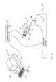
- the medical procedure simulation systemincludes a computer system 25 , an interface device 20 , an actual or mock endoscope 22 and a communications interface 24 for transferring signals between computer system 25 , interface device 20 and actual or mock endoscope 22 .
- Computer system 25preferably includes a monitor 28 , base 26 (e.g., including processor(s), memories and accompanying hardware), keyboard 27 and mouse 29 , and is typically implemented by a conventional or commercially available workstation, such as those manufactured by IBM, Dell or Silicon Graphics, Inc.
- the computer systemsimulates, via software, an endoscopic or other medical procedure (e.g., an interventional radiology procedure), while displaying a simulated particular bodily region of interest (e.g., a tracheobronchial tree having a plurality of segments) on monitor 28 .
- the simulation displaypreferably emulates an endoscopic video display of an image retrieved by a fiber-optic camera system integrated into an endoscope.
- An exemplary display of the simulation system showing a tracheobronchial treeis illustrated in FIG. 2 .
- Interface device 20includes at least one orifice, such as a simulated nostril, throat, anus, or puncture (as by trocar) etc., for receiving actual or mock endoscope 22 .
- Endoscope 22typically includes a handle 21 , working channel 15 , working channel tool 23 , thumb lever 19 and switches 18 .
- the endoscopeis typically inserted into an interface device orifice and manipulated to perform a simulated endoscopic procedure.
- Interface device 20measures manipulation of endoscope 22 and working channel tool 23 , and provides signals indicating the measured manipulation to computer system 25 .
- Computer system 25processes the signals to display, via monitor 28 , the internal bodily region of interest (e.g., a tracheobronchial tree as shown in FIG.
- Computer system 25further provides force feedback to the endoscope based on manipulation of the endoscope.
- Communications interface 24transfers the manipulation and force feedback signals between computer system 25 , interface device 20 and endoscope 22 .
- Working channel tool 23enables simulation of various devices, such as a needle transbronchial biopsy tool, a grasping bronchial biopsy tool, forceps, laser or other instrument that may be inserted within and manipulated via an endoscope working channel during an endoscopic procedure.
- the working channel toolis similar to a cable attached to an actual biopsy tool, forceps or transbronchial biopsy tool.
- a mock endoscope for the simulation systemtypically contains approximately ten inches of the working channel tool and permits the working channel tool to move within and external of the endoscope approximately three inches, or to be removed entirely and replaced by a different working channel tool. Translational and rotational motion of the working channel tool is generally measured by encoders (not shown) disposed within the endoscope.
- the working channelmay optionally include actuators to provide force feedback to the working channel tools.
- Outer tube 58includes cross-sectional dimensions greater than the cross-sectional dimensions of guide tube 34 such that a step or shoulder 104 is formed at the interface between the outer and guide tubes.
- An inner tube 56includes cross-sectional dimensions less than the cross-sectional dimensions of outer tube 58 , whereby the inner tube is disposed in slidable relation within the outer tube.
- Capture mechanism 38is disposed toward the proximal end of inner tube 56 and engages navigation tube 49 such that inner tube 56 is translated and rotated based on manipulation of endoscope 22 as illustrated in FIG. 4 .
- capture mechanism 38is disposed toward the proximal end of inner tube 56 and includes disc 72 , woven mesh tubular member 74 and substantially annular washers 68 , 76 , 78 .
- Disc 72is disposed at the capture mechanism distal end and is attached to washer 68 via fasteners 64 , whereby the washer is disposed proximally of the disc.
- the distal end of woven mesh tubular member 74is inserted through washer 68 and attached to disc 72 .
- the woven mesh tubular memberis typically constructed of spirally wound material and includes expandable and compressed states, whereby the woven mesh tubular member cross-sectional dimensions increase when the member is compressed and decrease when the member is expanded.
- the proximal end of woven mesh tubular member 74is inserted through washer 78 and attached to washer 76 .
- Washer 76is disposed proximally of washer 78 and is connected to washer 78 via fasteners 64 .
- a helical spring 70is disposed between washers 68 , 78 and about woven mesh tubular member 74 .
- the cross-sectional dimensions of the springare greater than the cross-sectional dimensions of the woven mesh tubular member and openings within washers 68 , 78 to permit the spring to enter expanded and compressed states.
- the springenables the woven mesh tubular member to enter the compressed and or expanded state in order to vary the tubular member cross-sectional dimensions for engaging and releasing navigation tube 49 .
- expansion of spring 70causes woven mesh tubular member 74 to expand, thereby extending the woven mesh tubular member and decreasing the cross-sectional dimensions of that member due to the spiral-shaped nature of the woven mesh material.
- compression of spring 70decreases the length of woven mesh tubular member 74 , thereby increasing the cross-sectional dimensions of the woven mesh tubular member.
- the differing cross-sectional dimensions of the woven mesh tubular memberenable capture mechanism 38 to securely grasp and release navigation tube 49 without electronic or other mechanical mechanisms as illustrated in FIGS. 5-6 .
- inner tube 56is disposed within outer tube 58 with washer 76 positioned adjacent shoulder 104 of outer tube 58 ( FIG. 5 ).
- Magnets 96 , 98are respectively disposed toward the distal ends of the inner and outer tubes to maintain inner tube 56 within outer tube 58 and bias spring 70 to a compressed state.
- the compressed state of spring 70causes woven mesh tubular member 74 to enter a compressed state, thereby increasing the woven mesh tubular member cross-sectional dimensions.
- Navigation tube 49is inserted into interface device 20 ( FIG.
- Navigation tube 49extends through woven mesh tubular member 74 and interfaces disc 72 . Additional force applied to the endoscope enables navigation tube 49 to overcome the attraction force of magnets 96 , 98 and to move inner tube 56 distally relative to outer tube 58 ( FIG. 6 ). The motion of inner tube 56 enables spring 70 to expand, thereby causing woven mesh tubular member 74 to enter an expanded state with decreased cross-sectional dimensions.
- the decreased cross-sectional dimensions of the woven mesh tubular membersecurely grip navigation tube 49 to enable inner tube 56 to be manipulated based on forces applied to endoscope 22 .
- inner tube 56When navigation tube 49 is removed from interface device 20 , inner tube 56 is moved proximally within outer tube 58 to the state where washer 76 contacts shoulder 104 then causing washer 68 to oppose the force of spring 70 .
- the springsubsequently transitions from an expanded ( FIG. 6 ) to a compressed state ( FIG. 5 ) as described above.
- the compression of spring 70causes woven mesh tubular member 74 to enter a compressed state, thereby increasing the cross-sectional dimensions of the woven mesh tubular member.
- the attraction force of magnets 96 , 98maintain inner tube 56 within outer tube 58 , thereby maintaining the compressed state of spring 70 and woven mesh tubular member 74 .
- the increased cross-sectional dimensions of woven mesh tubular member 74exceeds the cross-sectional dimensions of navigation tube 49 , thereby enabling the woven mesh tubular member to release the navigation tube to permit removal of the navigation tube from the interface device.
- Trolley assembly 46that enables measurement of translational and rotational motion of navigation tube 49 via sensed motion of inner tube 56 .
- Trolley assembly 46is attached to a belt 44 that extends between and about a pair of pulleys 42 , 43 disposed on corresponding supports 39 , 41 .
- Supports 39 , 41are separated by a distance similar to the length of inner tube 56 , and include guide rails 40 extending between the supports with belt 44 disposed between the guide rails.
- Trolley assembly 46includes openings defined in the trolley assembly portion adjacent belt 44 for receiving guide rails 40 to direct trolley assembly motion.
- a rotation encoder 30is disposed on the trolley assembly and includes a shaft that interfaces the distal end of inner tube 56 to measure rotational motion of navigation tube 49 , while a translation encoder 31 is disposed on support 41 to interface pulley 43 and measure translational motion of the navigation tube.
- additional translational force applied to the endoscopee.g., motion of the navigation tube into simulated lungs
- the trolley assembly motionmanipulates belt 44 about pulleys 42 , 43 , thereby causing the pulleys to rotate.
- a medical practitioneris able to view the inside lumen or other interior region of the bodily cavity.
- a bronchoscopemay be inserted into a nasal opening and extend into the lungs.
- a medical practitionertypically manipulates the bronchoscope in its degrees of freedom (e.g., translational, rotation and flexion of the bronchoscope distal tip) to safely navigate down a lumen or opening in branches of a bronchial tree.
- the bronchoscopetypically encounters bifurcations (e.g., the bronchial tree bifurcates into various lobes, segments and sub-segments) and may contact walls of the bronchi, whereby the medical practitioner feels forces on the bronchoscope.
- a force feedback unit 60is employed within the interface device. Specifically, force feedback unit 60 is disposed on support 39 adjacent pulley 42 to impart forces encountered during an actual procedure, such as touching lung walls or bronchial walls at a bifurcation during a bronchoscope examination. Force feedback unit 60 is typically implemented by an electromagnetic device and receives control signals from computer system 25 via communications interface 24 . Computer system 25 determines, based on manipulation of the endoscope, the feedback force to apply, and sends control signals to communications interface 24 .
- the communications interfaceincludes digital to analog converters (DAC) and converts the computer system control signals to analog signals in order to transmit the signals to the interface device to control force feedback unit 60 .
- DACdigital to analog converters
- the force feedback unitimparts a magnetic force on pulley 42 to impede or enhance pulley rotation and trolley assembly motion. The impeded motion requires additional force to be applied to the endoscope to overcome the magnetic force, while enhanced motion requires application of less force, thereby providing a realistic feel to the endoscopic procedure.
- thumb lever 19 of endoscope 22may be utilized to simulate flexing or bending of the navigation tube distal end.
- the endoscopetypically includes an encoder (not shown) to measure manipulation of thumb lever 19 and provide a signal to computer system 25 , via communications interface 24 , in substantially the same manner described above for the rotation and translation encoders.
- Manipulation of the thumb leverenables simulation of virtual camera motion at the distal end of the endoscope.
- the thumb levermay optionally include adjustable frictional resistance using any one of a number of damping mechanisms, and additionally may include computer controlled force feedback via an actuator (not shown).
- Switches 18 of endoscope 22may be used to simulate irrigation with fluids, suction of the fluids from the lungs and to control a simulated recording system that may capture video and/or still images from the monitor system.
- the switchesprovide signals to computer system 25 , via communications interface 24 , to enable the computer system to perform the desired simulation.
- a medical practitioner or usermanipulates an endoscope 22 , such as a bronchoscope, and inserts navigation tube 49 into a bodily opening or nostril 36 of mock head 62 .
- the endoscopeis typically manipulated in a manner similar to that utilized during an actual procedure.
- the endoscopeis held in one hand, while the other hand manipulates the navigation tube.
- Navigation tube 49traverses guide tube 34 and interfaces capture mechanism 38 .
- the capture mechanismengages navigation tube 49 as described above. Once navigation tube 49 engages the capture mechanism, inner tube 56 and navigation tube 49 are effectively mated such that translational and rotational motion of the distal tip of navigation tube 49 within the virtual patient is reflected by inner tube 56 .
- the translational and rotational motion of inner tube 56is measured to enable computer system 25 to simulate the movement of the endoscope within a virtual patient (e.g., the distance the navigation tube has been inserted into the virtual patient and rotation of the navigation tube).
- the navigation tubeapplies force to inner tube 56 via capture mechanism 38 .
- the inner tube translational motionmoves trolley assembly 46 between supports 39 , 41 , thereby causing belt 44 to rotate pulleys 42 , 43 .
- Translation encoder 31 attached to pulley 43measures pulley rotation and provides a signal to computer system 25 , via communications interface 24 , indicating translational motion of the navigation tube.
- Simulation of flexing the distal end of navigation tube 49is accomplished via manipulation of thumb lever 19 of endoscope 22 .
- the motion of the thumb leveris measured by an encoder (not shown), typically disposed within endoscope handle 21 , that provides a signal to computer system 25 , via communications interface 24 , indicating the motion of the thumb lever.
- Computer system 25processes the signal to determine flexing of the tube and a resulting simulated image produced from a camera based on the position of the flexed tube.
- the medical practitionermay perform a simulated biopsy.
- the biopsyis typically performed by an assistant upon verbal command during an actual procedure, however, the simulated biopsy is performed by computer system 25 as described below.
- a biopsy toolis selected, via computer system 25 , and working channel tool 23 is inserted into the endoscope and manipulated by the user to perform the biopsy.
- computer system 25displays simulated extension of the biopsy tool from the endoscope working channel (e.g., up to several centimeters beyond the distal end of the navigation tube).
- the working channel toolis typically shown in the simulated visual field of the simulated fiber-optic camera.
- the medical practitionercontinues to manipulate the working channel tool to position the tool adjacent lung tissue of the simulated patient.
- the medical practitionercommands computer system 25 , via keyboard 27 , to take a sample.
- Computer system 25proceeds to open and close biopsy forceps to simulate taking of a biopsy from lung tissue.
- the simulated procedureis similar to an actual procedure whereby an endoscope with a fiber optic camera at its distal tip is simulated by computer system 25 based on manipulation of endoscope 22 within interface device 20 .
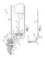
- interface device 120includes a housing or case 122 , a mock anatomical site 162 , such as a head, an angle bracket or support 116 for supporting head 162 and pivoting mechanisms 112 , 114 for enabling head 162 to pivot relative to housing 122 and support 116 , respectively.
- Housing 122includes front, rear and side walls that collectively define a housing interior.
- the interface device front wallis typically formed of overlapping sections, such as an upper section or overhang 152 and a lower section or flange 154 .
- Sensing and force-feedback assembly 110is disposed within housing 122 for measuring manipulation of and providing force-feed-back to endoscope navigation tube 49 during simulation of a medical procedure.
- the sensing assemblyincludes substantially the same components and functions in substantially the same manner as the interface device components described above to measure navigation tube manipulation and provide force-feedback.
- Mock head 162includes a nostril or orifice 136 that serves as an entry site for receiving the endoscope navigation tube.
- Angle bracket 116is attached to lower section or flange 154 of the interface device front wall.
- the angle bracketincludes an interface section 170 that is attached, via pivoting mechanism 112 , to the interface device front wall, an anatomical site section 172 that supports head 162 , and an angled section 174 that extends between the interface and anatomical site sections at an angle relative to each of those sections.
- the angle bracket sectionsmay be connected at any desired angle.
- Mock head 162is affixed to a backing plate 118 via fasteners 126 .
- Plate 118is attached to pivoting mechanism 114 to enable head 162 to pivot relative to angle bracket 116 .
- pivoting mechanism 114includes a ring 130 rotatably coupled to a fixed, substantially conical retainer 128 .
- Pivoting mechanism 112is disposed between angle bracket 116 and the interface device front wall. Pivoting mechanism 112 provides an additional degree of freedom for mock head 162 substantially orthogonal to the degree of freedom provided by pivoting mechanism 114 . Pivoting mechanism 112 includes a ring 134 that is rotatably coupled to a fixed, substantially annular retainer 144 and attached to angle bracket 116 via fasteners 140 . The retainer is attached to the lower section or flange 154 of housing front wall via fasteners 142 . Ring 134 is substantially similar to ring 130 of pivoting mechanism 114 , and enables the angle bracket to pivot relative to housing 122 .
- An outer tube 158extends from nostril 136 through pivoting mechanism 114 (e.g., retainer 128 and ring 130 ) and angle bracket 116 and curves toward pivoting mechanism 112 disposed on flange 154 of interface device front wall. Outer tube 158 extends from the curved portion through pivoting mechanism 112 (e.g., retainer 144 and ring 134 ) and angle bracket 116 into the housing interior to sensing assembly 110 . Outer tube 158 is similar to and performs the functions of the outer and guide tubes described above.
- the outer tubeis rotatable about its longitudinal axis via pivoting mechanism 112 (e.g., retainer 144 and ring 134 ), whereby the interior of conical retainer 128 surrounds and forces the outer tube to rotate relative to the housing when head 162 is pivoted via pivoting mechanism 112 .
- pivoting mechanism 112e.g., retainer 144 and ring 134
- an inner tube 156is disposed within outer tube 158 to capture and emulate endoscope navigation tube motion as illustrated in FIG. 8 .
- inner tube 156includes cross-sectional dimensions less than the cross-sectional dimensions of outer tube 158 , whereby the inner tube is disposed in slidable relation within the outer tube.
- a flexible torsion tube 148is disposed at the proximal end of the inner tube, while an instrument capture mechanism 138 is disposed at the proximal end of torsion tube 148 .
- a plurality of substantially annular spacers 150are disposed about the torsion tube between the inner tube and capture mechanism.
- Capture mechanism 138is substantially similar to the instrument capture mechanism described above.
- Inner tube 156is initially positioned within outer tube 158 such that torsion tube 148 flexes to traverse the outer tube curved portion and position the capture mechanism adjacent nostril 136 .
- mechanism 138captures the tube, thereby enabling inner tube 156 to emulate the endoscope navigation tube manipulation and facilitate measurement of that manipulation via sensing assembly 110 in substantially the same manner described above.
- Pivoting mechanisms 112 , 114provide degrees of freedom that enable mock head 162 to be pivoted or rotated into various desired or appropriate positions for simulation.
- mock head 162may be pivoted to a position as shown in FIG. 7 , thereby simulating a patient lying on their back.
- head 162may be pivoted from the patient back lying position approximately ninety-degrees relative to housing 122 , via mechanism 112 , to simulate a patient lying on their side.
- head 162may be pivoted from the patient side lying position approximately ninety-degrees relative to the angle bracket, via mechanism 114 , to simulate a seated patient, while mechanism 112 may further enable pivoting of head 162 to simulate a partially reclined seated patient.
- mock head 162can be pivoted into multiple positions via mechanisms 112 , 114 that provide substantially orthogonal degrees of freedom.
- interface device 120Operation of interface device 120 is described with reference to FIGS. 1 , 7 - 8 .
- head 162is manipulated via mechanisms 112 , 114 to any desired position or orientation suitable for a particular simulation.
- the medical procedure simulation systemsubsequently performs a simulation in substantially the same manner described above.
- a medical practitioner or usermanipulates an endoscope 22 and inserts navigation tube 49 into a bodily opening or nostril of mock head 162 .
- Navigation tube 49interfaces capture mechanism 138 , thereby enabling inner tube 156 to reflect translational and rotational motion of the navigation tube.
- Sensing assembly 110measures the manipulation of the navigation tube and provides information to computer system 25 via communications interface 24 to enable simulation of force-feedback and traversal of the endoscope within a virtual patient.
- Endovascular proceduresgenerally require a medical practitioner to guide instruments through a patient vascular system (e.g., including arteries and veins) to access a remote site of interest where the instruments are utilized.
- the remote sitemay be located within or adjacent a vein or artery, or may be located within the heart itself (e.g., during procedures of heart valve repair or heart pacing leads placement or manipulation).
- the sheathprovides an opening into a vein or artery, whereby the dilator is removed from the sheath lumen and replaced by a catheter that is inserted into the sheath and manipulated through the vein or artery based on a fluoroscope display to a site of interest.
- a guidewiremay be inserted into the catheter to extend beyond the catheter tip for navigation around difficult passages in the patient vascular tree. The catheter may then be navigated by the wire through the difficult passage.
- the medical practitioneris required to control the depth (e.g., translational) and rotational orientation of the tips of several mutually co-axial instruments in order to successfully complete that procedure.
- long flexible instrumentse.g., catheters, guidewires, etc.
- the distance the instrument is inserted within the body and the angle of rotation of the instrument distal endare frequently a function of a large quantity of variables, such as the materials constructing the instrument, the portion of the instrument disposed within the patient body, and the forces encountered by the instrument.
- Computer system 25processes the signals to display, via monitor 28 , the internal bodily region of interest, while adjusting the display (e.g., vascular models) to reflect manipulation of the wire, catheter and sheath.
- interface device 314may provide force feedback to the wire, catheter and sheath (e.g., oppose or enable rotational and/or translational motion of these instruments) in accordance with control signals from the computer system to simulate the forces encountered during an actual procedure.
- Communications interface 24transfers the manipulation and force feedback signals between computer system 25 and interface device 314 in substantially the same manner described above. It is to be understood that the interface device may interface various instruments (e.g., endoscopes, tubes, navigation instruments, etc.) to a simulation system to simulate a variety of medical procedures in substantially the same manner described below.
- an exemplary instrument assembly for use in an interventional radiology procedure and for interfacing computer system 25 via interface device 314is illustrated in FIG. 10 .
- an assembly 330includes wire 302 , catheter 304 and sheath 306 .
- Catheter 304is disposed within and extends beyond the sheath proximal and distal ends, while wire 302 is disposed within and extends beyond the catheter proximal and distal ends.
- This nested arrangementenables independent manipulation of the instruments in order to navigate within a patient and utilize tools or other implements disposed at the distal ends of the instruments, such as a balloon or other implement.
- the proximal portions of the wire, catheter and sheathare each located external of the interface device, and each of these instruments may include a corresponding handle 308 , 310 , 312 disposed toward their proximal end to enable manipulation of that instrument.
- the distal portions of the instrumentsare similarly nested to enable the interface device to measure manipulation of and apply force feedback to a particular instrument.
- interface device 314includes a frame 410 having a base 430 and supports 432 , 434 , and a carrier assembly 412 disposed between the supports.
- Support 432extends from the proximal end of, and substantially perpendicular to, the base, while support 434 extends from the distal end of the base substantially parallel to support 432 .
- An outer tube 416is attached to frame 410 and extends from support 432 toward carrier assembly 412 , while an inner tube 414 is disposed within the outer tube and extends beyond the outer tube distal end to the carrier assembly.
- the outer tubeincludes cross-sectional dimensions greater than the cross-sectional dimensions of the inner tube such that the inner and outer tubes are in slidable relation.
- the proximal end of outer tube 416is disposed within an opening or orifice 419 defined in support 432 for receiving a distal end of a catheter 418 . Since the catheter is flexible, the catheter tends to buckle under compressive stress induced by translational motion of the catheter into the interface device. However, the combination of the slidable inner tube and outer tube provide a telescoping action that stabilizes the catheter and prevents buckling.
- interface device 314Operation of interface device 314 is described with reference to FIG. 11 a .
- catheter 418is inserted into orifice 419 and manipulated by a user to traverse the outer and inner tubes to carrier assembly 412 .
- the catheterfurther extends through the carrier support opening and encoder shaft, whereby the catheter is firmly engaged by set screw 403 .
- set screw 403Once the catheter is engaged, further insertion of the catheter into the interface device by the user causes the carrier assembly to move toward support 434 .
- force applied to remove the catheter from the interface devicecauses the carrier assembly to move toward support 432 .
- the carrier assembly motionenables belt 424 to traverse and rotate pulleys 420 , 426 .
- Encoder 422measures the rotational motion of pulley 420 , and hence, the translational motion of the catheter, and provides a signal to the computer system via the communications interface.
- Rotational motion of the catheterenables tubular shaft 440 to rotate since the catheter is connected to the shaft via set screw 403 .
- Encoder 404measures the rotational motion of tube 440 , and hence, the rotational motion of the catheter, and provides a signal to the computer system via the communications interface.
- the interface devicemeasures both the translational and rotational motion of the catheter, whereby these motions are partially dependent upon the force applied by the user to the catheter proximal end to enable catheter motion.
- the computer systemprocesses the encoder signals to enable the simulation to reflect catheter motion, and may provide control signals to actuator 428 to provide force feedback.
- actuator 428may apply force to pulley 426 to enhance or oppose the catheter translational motion.
- the applied forcemay impede pulley and belt motion, thereby requiring additional force to manipulate the catheter.
- the applied forcemay facilitate rotation of the pulley and enhance belt motion, thereby requiring less force to manipulate the catheter.
- the actuatorapplies force to pulley 426 in accordance with control signals determined by the computer system, whereby the forces may cause catheter 418 to store a certain amount of hysteresis or play for both translational and rotational motion (e.g., compression or stretching). This hysteresis or play is the difference between observed rotational and/or translational motion at the proximal and distal ends of catheter 418 .
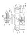
- interface device 314includes a frame 504 having a base 540 and supports 542 , 544 , and a carriage assembly 520 disposed between the supports.
- Base 540includes legs 528 , preferably constructed of rubber, to stabilize the device.
- Support 542extends from a proximal portion of, and substantially perpendicular to, base 540 , while support 544 extends from the distal end of the base substantially parallel to support 542 .
- a bracket 506is disposed proximally of support 542 on base 540 , and supports a pulley 510 and an actuator 508 connected to the pulley via a shaft.
- Guide openings 523 , 525are defined in each bellows section to receive and fit loosely over corresponding guide rods 516 , 518 , respectively, while stabilization opening 521 is defined toward the approximate center of each section to receive and prevent buckling of the catheter.
- the bellowsis supported by guide rods 516 , 518 , and is typically not directly connected to the supports or carriage assembly.
- carriage assembly 520includes a carriage 562 , preferably a machined block of aluminum, having a guide 590 disposed on a top surface to engage guide rod 516 , and a channel 592 formed through the carriage to engage guide rod 518 .
- a fastener 596extends down from a carriage side to engage belt 512 ( FIG. 12 ), while an encoder 524 is disposed adjacent guide 590 .
- a catheter channel 594is formed through the intermediate portion of the carriage to receive catheter 500 from bellows 522 .
- a collet bearing 566is typically pressed into the distal portion of carriage 562 coincident channel 594 .
- An encoder disk 550is pressed onto the proximal end of collet 568 , while an encoder sensor 558 fits over the disk and is attached to carriage 562 .
- Each of the above-described elements of the carriage assemblyincludes an opening to enable instruments, such as catheters, to be inserted into and/or through the assembly depending upon instrument dimensions as described above. Stabilization holes 521 are maintained coincident the element openings to stabilize the instrument and enable the instrument to be inserted into the carriage assembly.
- the carriage assemblytraverses frame 504 via guide rods 516 , 518 and is limited to translational motion as described below.
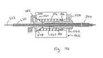
- FIGS. 14 a - 14 dOperation of the collet to engage an appropriately dimensioned instrument is illustrated in FIGS. 14 a - 14 d .
- lever 582is pivoted about pivot pin 564 in a counterclockwise direction (e.g., toward the interface device proximal end), thereby forcing collet expander 578 , disposed proximate the lever, further into the carriage assembly.
- the collet expandercompresses spring 576 , and includes a conical proximal tip that separates the collet distal end to enable jaws 567 to enter an open state for receiving an appropriately dimensioned instrument ( FIG. 14 a ).
- the collet proximal portionis attached to encoder disk 550 , whereby the collet rotates, via bearing 566 , to reflect catheter rotation.
- Encoder disk 550similarly rotates with collet 568 , whereby encoder sensor 558 senses marks on the disk to measure rotation of the disk and the catheter.
- the colletsmay be of varying dimensions to enable capture of a particular instrument.
- an assembly including wire 632 , inner catheter 630 and catheter 500is inserted into carriage 562 ( FIG. 14 d ), whereby each of these instruments is independently manipulable.
- the colletincludes sufficient dimensions to enable the assembly to traverse the carriage, while permitting jaws 567 to grasp catheter 500 in substantially the same manner described above.
- the carriage assemblythus measures motion of catheter 500 , while wire 632 and inner catheter 630 extend to corresponding carriages (e.g., FIG. 15 ) having appropriately dimensioned collets to grasp and measure motion of these instruments in substantially the same manner described above.
- catheter 500is inserted into orifice 501 by a user and traverses tube 502 and bellows 522 until being engaged by collet 568 of carriage assembly 520 .
- Lever extension 583is manipulated toward support 544 to pivot lever 582 and enable the collet to grasp the catheter as described above.
- the levermay alternatively be forced toward the interface device proximal end to actuate a quick-release as described above. Further insertion of catheter 500 into the interface device by the user forces carriage 520 to move toward support 544 .
- encoder 524senses marks on encoder bar 526 to measure translational motion of the carriage assembly, and hence, the catheter.
- the translational motion measured by the encoderdiffers from the translational motion of the catheter relative to the orifice since the catheter is subject to expansion and compression due to forces exerted by the user.
- the encoderprovides a signal indicating the measured translational motion of the catheter to the computer system via the communications interface.
- rotational motion of the catheterrotates encoder disk 550 , thereby enabling sensor 558 to measure that rotational motion.
- the sensorprovides a signal indicating the measured rotational motion to the computer system via the communications interface.
- the computer systemprocesses the signals to update the display and determine force feedback signals.
- Force feedbackis accomplished via actuator 508 affecting pulley motion. Since the carriage assembly is connected to belt 512 , the carriage assembly motion causes belt 512 to traverse and rotate pulleys 510 , 514 . Control signals from the computer system control the actuator to impede or enhance rotation of pulley 510 . When pulley rotation is impeded, additional force is required to manipulate translational motion of the catheter, while enhancing pulley rotation enables less force to manipulate the catheter. Force feedback is typically utilized to simulate forces encountered during an actual procedure when inserting or removing a catheter within a patient. Thus, the user feels at the proximal end of the instrument forces imparted to the instrument distal end based on a simulated procedure.
- FIG. 15An alternative interface device configuration for accommodating nested and/or independently inserted instruments is illustrated in FIG. 15 .
- the interface deviceis substantially similar to, and functions in substantially the same manner as, the interface device described above for FIGS. 12 , 13 a - 13 b and 14 a - 14 d except that the interface device of FIG. 15 accommodates nested and/or independently inserted instruments.
- the interface deviceincludes a base 700 for receiving frame 504 and its associated components, and a cover 704 .
- the cover proximal portiontypically includes openings or mock orifices 712 of a simulated anatomy (not shown), typically mounted on a platform 702 , to enable instruments to be inserted into the interface device.
- Frame 504is substantially similar to the frame described above for FIG. 12 and includes components for accommodating independently inserted instruments.
- the independently inserted instrumentsare accommodated by respective configurations 722 and 724 arranged in parallel relation.
- Configuration 724is substantially similar to, and functions in substantially the same manner as, the configuration of FIG. 12 and receives an instrument, such as a catheter, through tube 502 .
- Catheter motionis measured by carriage assembly 520 , whereby signals indicating the measured motion are provided to the computer system to determine force feedback and update the display in substantially the same manner described above.
- Carriage assemblies 706 , 708 , 710are substantially similar to and measure rotational and translational motion of a corresponding instrument in substantially the same manner described above for carriage assembly 520 .
- Carriage assemblies 706 , 708 , 710are each connected to respective belts disposed about and extending between the proximal and distal (partially shown) pulleys. The actuators and pulleys enable the carriage assemblies to provide force feedback to the particular instrument engaged by that assembly in substantially the same manner described above for carriage assembly 520 .
- Bellows 522are disposed between support 542 and carriage assembly 706 , between carriage assemblies 706 and 708 and between carriage assemblies 708 and 710 , to prevent buckling of the particular instruments as described above.
- the interface devicemay include any quantity (e.g., at least one) of configurations each having any quantity (e.g., at least one) of carriage assemblies to accommodate any desired quantity of instruments.
- an instrument assembly(not shown e.g., including a wire, catheter and sheath) and another instrument (e.g., a catheter) are inserted by a user through corresponding orifices 712 , 714 and traverse tube 502 to extend to the carriage assemblies.
- Configuration 724measures manipulation of the instrument (e.g., catheter) as described above, while the instrument assembly extends through carriage assemblies 706 , 708 and 710 .
- Each carriage assembly 706 , 708 , 710includes a collet of an appropriate dimension and captures, measures manipulation of, and provides force feedback to, a particular instrument (e.g., sheath, catheter and wire, respectively) as described above.
- Configurations 722 , 724operate in parallel to provide the computer system with measured manipulation signals for their corresponding instruments to enable the computer system to determine force feedback and update the display to reflect the manipulations for each instrument in substantially the same manner described above.
- the interface device of FIG. 11 amay include plural carrier assemblies to handle plural instruments, similar to the manner described above.
- the interface devicemay further include an automatic capture and release mechanism as illustrated in FIGS. 17 a - 17 b .
- the interface deviceincludes a configuration, similar to configuration 724 described above for FIG. 15 , having carriage assemblies 706 (not shown), 708 , 710 separated by bellows (not shown) and arranged in a manner substantially similar to FIG. 16 .
- the mechanismis described with reference to carriage assemblies 708 , 710 for illustrative purposes, whereby the mechanism may equally be employed between the remaining carriage assemblies or a carriage assembly and the frame as described below.
- Carriage assemblies 708 , 710are substantially similar to carriage assemblies 708 , 710 described above except that the carriage assemblies further include components to facilitate an automatic capture and release mechanism.
- carriage assembly 710includes a bracket 814 extending from the carriage assembly upper portion, while carriage assembly 708 includes a bracket 806 extending from its upper portion.
- a rod 804is disposed through openings defined in brackets 806 , 814 to couple carriage assemblies 708 , 710 .
- Bracket 814includes a spring screw 816 having a spring-loaded nylon plunger to engage rod 804 .
- the spring screwmay be adjusted to control application of frictional force to rod 804 , thereby simulating friction that may be encountered between nested instruments (e.g., wire 302 and catheter 304 ).
- Bracket 806includes a set screw 808 for engaging rod 804 , whereby translational motion of the rod is initiated in response to translational motion of carriage assembly 708 .
- a stop 818is disposed toward the distal and of rod 804 via a set screw 820 . The stop limits the distance that wire 302 may be inserted into the interface device relative to catheter 304 . This may be utilized to simulate hollow devices having a closed end, such as a heart placing lead.
- a wire styletis utilized to stiffen the lead for navigation into the heart, whereby the stylet is removed at the completion of the procedure to return the lead to a flexible state. Additional stylet insertion is typically prevented by the end of the lead, which may be simulated by adjustment of stop 818 .
- the travelercontacts projection 840 , and pivots lever extension 583 toward carriage assembly 710 in response to overcoming the bias forces on the lever to release wire 302 ( FIG. 17 b ).
- Wire 302is released from carriage assembly 710 , and carriage assemblies 708 , 710 maintain their positions relative to each other due to the tension of spring 832 holding extension 844 against the proximal side of traveler 810 .
- the wiremay be withdrawn and exchanged for another instrument as described below.
- a new instrumentmay be inserted through catheter 304 and into the interface device.
- the instrumentis inserted to extend to carriage assembly 710 .
- Additional insertion forcecauses carriage assembly 710 to move distally and away from carriage assembly 708 .
- Section 844 of rocker 824interfaces traveler 810 , whereby the rocker is subsequently pivoted in a clockwise direction.
- Stop pin 838limits rotation of rocker 824 when the rocker rotates sufficiently to enable section 842 to be positioned proximate the distal side of traveler 810 .
- the spring bias of lever extension 583pivots the lever to capture the new instrument ( FIG. 17 a ) as described above.
- each carriage assembly 706 , 708 , 710typically includes the mechanism components of carriage assemblies 708 , 710 described above (e.g., components 806 and 890 shown on carriage assembly 708 in FIGS. 17 a - 17 b ).
- the appropriate componentse.g., the carriage assemblies may not include or utilize some components; for example, bracket 806 of carriage assembly 710 (not shown) is typically not utilized since that assembly is not coupled to subsequent assemblies in the particular arrangement) are arranged to interface a corresponding rod as described above, whereby an independent rod is disposed between carriage assemblies 708 , 710 , between carriage assemblies 706 , 708 , and between carriage assembly 706 and an interface device frame.
- the rod associated with carriage assembly 706is attached to the frame to serve as a ground, similar to the function of bracket 806 described above.
- the mechanismis implemented to facilitate automatic capture and release of the sheath, catheter and wire by respective carriage assemblers 706 , 708 , 710 in substantially the same manner described above.
- the automatic capture and release mechanismmay alternatively utilize magnets (e.g., a magnet disposed on a carriage assembly and another magnet disposed on rod 804 or other support) to generate a magnetic force to overcome the lever bias and pivot the lever to desired positions, similar to the magnets described above for FIG. 3 .
- the automatic capture and release mechanismmay be utilized in the system of FIG. 3 to maintain the inner tube within the outer tube.
- the mechanism componentsmay be attached to the inner and outer tubes in a manner similar to the carriage assembly arrangement described above.
- the interface devices of the present inventionmay be utilized with various elongated or other instruments (e.g., endoscopes, catheters, wires, sheaths, etc.) for simulating a variety of medical procedures, and are not limited to the specific instruments or applications disclosed herein.
- the computer system of the medical procedure simulation systemmay be implemented by any conventional or other processing system.
- the communications interfacemay include any circuitry (e.g., analog to digital converters, digital to analog converters, etc.) and/or processors to transfer and/or convert signals for compatibility between an interface device and processing system. The functions of the communications interface may further be performed within the interface device or processing system.
- the endoscope or other instrumentsmay include various switches, buttons, dials or levers to simulate various events.
- the endoscope switchesmay be used to simulate irrigation and suction and video captures including freeze frame and returning to dynamic video capture.
- the interface device and instrument capture mechanismmay be utilized with actual endoscopes to permit medical practitioners to train with instruments used during endoscopic procedures.
- the endoscopemay further include force feedback on the various switches or levers. The force feedback may be applied by an actuator configured to apply a static or dynamic force to the endoscope component. The actuator may be adjusted to provide a desired force.
- the encoders of the interface devices and instrumentsmay be implemented by any conventional or other encoders or devices, such as an optical encoder, an analog encoder or a potentiometer.
- the translational encoders of the interface devicesmay alternatively be implemented by a linear encoder reading a linear target strip, typically including light and dark bands, disposed along a motion path of the trolley, carrier or carriage.
- Force feedbackmay be provided by the interface devices via a passive or active braking mechanism or an active motor or other actuator attached to the trolley, carrier or carriage that utilizes frictional forces to impede motion (e.g., friction force against the frame, guide rods or guide rails).
- additional force feedback unitsmay be employed, similar to force feedback units described above, to impede rotational motion of instruments.
- the interface devicesmay utilize any anatomical sites, such as a nostril, mouth, ear, anus, urethra, etc. Further, any types of orifices may be utilized such as orifices made surgically (e.g., an opening made in the stomach for laparoscopic procedures).
- the interface devices described abovemay each include a pivotable entry site, whereby the site may be pivoted to any desired position or orientation.
- the interface devicesmay include any conventional or other types of pivoting mechanisms that can pivot the site in any quantity of or any particular degree of freedom.
- the simulation systemmay similarly simulate any desired anatomical site or orifice.
- the interface devicesmay include additional encoders as described above to measure the entry site orientation and enable the simulation system to simulate a procedure based on that orientation.
- the capture mechanismmay be implemented by any conventional or other devices, such as a collet (e.g., any type of standard collet (e.g., spring or screws)), chuck, quick connect (e.g., standard quick connects, such as those used for high pressure hoses), or quick-disconnect type devices that enable transmission of force and torque.
- the capture mechanismmay utilize mechanical, magnetic (e.g., solenoid and plunger), air pressure, or other devices to effect capture.
- the automatic capture mechanismmay utilize sensors and computer control to sense when to capture and release.
- an instrumentmay be modified at the tip to fit over an expandable male fitting inside the interface device (e.g., scissors type, balloon, balls forced outward by a conical wedge, etc.).
- the capture mechanism and colletmay be of any size or shape to accommodate a particular instrument.
- the carrier or carriagemay be supported via guide rods, but may alternatively be supported via air bearings where the carrier or carriage includes a flat base supported by a surface with holes through which air is forced providing a thin layer of air between the carrier or carriage and support surface, thus a very low friction carrier or carriage friction guide.
- the carriagemay utilize any conventional levers or switches manipulated in any fashion to facilitate capture and release.
- An interface devicemay include any quantity (e.g., at least one) of trolleys, carriers and carriages to accommodate any quantity of nested or other instruments.
- the various encoders, actuators, pulleys, belts and other components of the present inventionmay be implemented by any conventional or other types of components performing the above-described functions.
- the componentsmay be of any shape or size, may be constructed of any suitable materials, and may be arranged in any fashion within the interface devices.
- the trolley, carrier and carriagesmay be of any shape or size, and may move via any conventional or other devices, such as wheels, guide rails, tracks, sufficient slippery surface including air bearings, etc.
- the beltsmay be constructed of any suitable material, and may be implemented by any belt, cable, rope, chain or other suitable device.
- the beltsmay be disposed in any fashion within the interface device.
- the pulleysmay be implemented by any type of pulley, gear or other device compatible with the belt.
- the set screws utilized in the present inventionmay be implemented by any conventional set screws or any other conventional device for grasping an instrument.
- the inner or other interface device tubesmay be attached to the frame and/or trolley, carrier, or carriage via any conventional or other techniques.
- the bellowsmay be of any quantity, shape or size and may be constructed of any suitable materials.
- the bellowsmay be implemented by any device capable of supporting an instrument and preventing buckling.
- the anti-buckling function provided by telescoping tubes or by bellows hereinmay also be provided by a tube which has been slit to enable a portion of the carriage (e.g. the capture mechanism and zero or more sensors) and the medical tool to move inside the tube while the remainder of the carriage moves outside the slit.
- the slitis of sufficiently small width to prevent the medical tool from buckling out through the slit, but is of a sufficiently wide dimension so as to allow the two portions of the carriage inside and outside the tube to be coupled.
- a long hole drilled close to and parallel to the surface of a solid material, with a slit cut into the material extending into the holemay be substituted for the slit tube.
- the foam blockmay be implemented by any sufficiently resilient material.
- the automatic capture mechanismmay utilize rods of any quantity (e.g., at least one), shape (e.g., round or rectangular) or size.
- the mechanismmay utilize any mechanical, electrical or other forces to pivot the lever for capture or release, such as magnets, springs, rubber bands, etc. Similarly, these devices may be utilized with the inner and outer tube mechanism to enable capture and release.
- the mechanismmay be employed in any quantity to automatically engage particular instruments, and may extend to any number of mutually coaxial instruments.
- the various interface device embodimentsmay be implemented either individually or in any combination to accommodate various instruments. Further, the various manners of measuring instrument manipulation and providing force feedback within the interface devices may be utilized in any of the above-described embodiments.
- the inventionmakes available a novel interface device and method for interfacing instruments to medical procedure simulation systems wherein various instruments are interfaced to a medical procedure simulation system to simulate performance of a variety of medical procedures.
Landscapes
- Engineering & Computer Science (AREA)
- General Physics & Mathematics (AREA)
- Health & Medical Sciences (AREA)
- Physics & Mathematics (AREA)
- Computational Mathematics (AREA)
- Mathematical Optimization (AREA)
- Medical Informatics (AREA)
- Medicinal Chemistry (AREA)
- Chemical & Material Sciences (AREA)
- Algebra (AREA)
- Radiology & Medical Imaging (AREA)
- Pulmonology (AREA)
- Mathematical Analysis (AREA)
- General Health & Medical Sciences (AREA)
- Mathematical Physics (AREA)
- Pure & Applied Mathematics (AREA)
- Business, Economics & Management (AREA)
- Educational Administration (AREA)
- Educational Technology (AREA)
- Theoretical Computer Science (AREA)
- Endoscopes (AREA)
Abstract
Description
Claims (20)
Priority Applications (1)
| Application Number | Priority Date | Filing Date | Title |
|---|---|---|---|
| US11/204,646US8480406B2 (en) | 1996-09-04 | 2005-08-15 | Interface device and method for interfacing instruments to medical procedure simulation systems |
Applications Claiming Priority (7)
| Application Number | Priority Date | Filing Date | Title |
|---|---|---|---|
| US2543396P | 1996-09-04 | 1996-09-04 | |
| US08/923,477US6106301A (en) | 1996-09-04 | 1997-09-04 | Interventional radiology interface apparatus and method |
| US7267298P | 1998-01-28 | 1998-01-28 | |
| US10566198P | 1998-10-26 | 1998-10-26 | |
| US11654599P | 1999-01-21 | 1999-01-21 | |
| US09/237,969US6929481B1 (en) | 1996-09-04 | 1999-01-27 | Interface device and method for interfacing instruments to medical procedure simulation systems |
| US11/204,646US8480406B2 (en) | 1996-09-04 | 2005-08-15 | Interface device and method for interfacing instruments to medical procedure simulation systems |
Related Parent Applications (1)
| Application Number | Title | Priority Date | Filing Date |
|---|---|---|---|
| US09/237,969ContinuationUS6929481B1 (en) | 1996-09-04 | 1999-01-27 | Interface device and method for interfacing instruments to medical procedure simulation systems |
Publications (2)
| Publication Number | Publication Date |
|---|---|
| US20060046235A1 US20060046235A1 (en) | 2006-03-02 |
| US8480406B2true US8480406B2 (en) | 2013-07-09 |
Family
ID=34831474
Family Applications (4)
| Application Number | Title | Priority Date | Filing Date |
|---|---|---|---|
| US09/237,969Expired - LifetimeUS6929481B1 (en) | 1996-09-04 | 1999-01-27 | Interface device and method for interfacing instruments to medical procedure simulation systems |
| US10/657,079Expired - Fee RelatedUS7833018B2 (en) | 1996-09-04 | 2003-09-09 | Interface device and method for interfacing instruments to medical procedure simulation systems |
| US10/657,144Expired - Fee RelatedUS7931470B2 (en) | 1996-09-04 | 2003-09-09 | Interface device and method for interfacing instruments to medical procedure simulation systems |
| US11/204,646Expired - Fee RelatedUS8480406B2 (en) | 1996-09-04 | 2005-08-15 | Interface device and method for interfacing instruments to medical procedure simulation systems |
Family Applications Before (3)
| Application Number | Title | Priority Date | Filing Date |
|---|---|---|---|
| US09/237,969Expired - LifetimeUS6929481B1 (en) | 1996-09-04 | 1999-01-27 | Interface device and method for interfacing instruments to medical procedure simulation systems |
| US10/657,079Expired - Fee RelatedUS7833018B2 (en) | 1996-09-04 | 2003-09-09 | Interface device and method for interfacing instruments to medical procedure simulation systems |
| US10/657,144Expired - Fee RelatedUS7931470B2 (en) | 1996-09-04 | 2003-09-09 | Interface device and method for interfacing instruments to medical procedure simulation systems |
Country Status (1)
| Country | Link |
|---|---|
| US (4) | US6929481B1 (en) |
Cited By (20)
| Publication number | Priority date | Publication date | Assignee | Title |
|---|---|---|---|---|
| US20090208915A1 (en)* | 2008-02-15 | 2009-08-20 | Pugh Carla M | Clinical assessment and training system |
| US20120146632A1 (en)* | 2009-07-20 | 2012-06-14 | Koninklijke Philips Electronics N.V. | Apparatus and method for influencing and/or detecting magnetic particles |
| RU2546406C1 (en)* | 2013-11-29 | 2015-04-10 | Общество с ограниченной ответственностью "Эйдос-Медицина" | Drive for tactile feedback generation to load instrument |
| US9361809B1 (en) | 2015-03-30 | 2016-06-07 | Cae Inc. | Tracking system |
| US9361808B1 (en) | 2015-03-30 | 2016-06-07 | Cae Inc. | Tracking system |
| US20170249866A1 (en)* | 2016-02-26 | 2017-08-31 | Cae Healthcare Canada Inc. | Apparatus for simulating insertion of an elongated instrument into a structure and medical insertion simulator |
| US20170249865A1 (en)* | 2016-02-26 | 2017-08-31 | Cae Healthcare Canada Inc. | Apparatus for simulating insertion of an elongated instrument into a structure providing axial rotating connection of the elongated instrument to a carriage |
| US20170249867A1 (en)* | 2016-02-26 | 2017-08-31 | Cae Healthcare Canada Inc. | Apparatus for simulating insertion of an elongated instrument into a structure including a pulley and a pulley position sensing arrangement |
| US9847044B1 (en) | 2011-01-03 | 2017-12-19 | Smith & Nephew Orthopaedics Ag | Surgical implement training process |
| US10380919B2 (en) | 2013-11-21 | 2019-08-13 | SonoSim, Inc. | System and method for extended spectrum ultrasound training using animate and inanimate training objects |
| US10380920B2 (en) | 2013-09-23 | 2019-08-13 | SonoSim, Inc. | System and method for augmented ultrasound simulation using flexible touch sensitive surfaces |
| US10613629B2 (en) | 2015-03-27 | 2020-04-07 | Chad Laurendeau | System and method for force feedback interface devices |
| US10810907B2 (en) | 2016-12-19 | 2020-10-20 | National Board Of Medical Examiners | Medical training and performance assessment instruments, methods, and systems |
| US11495142B2 (en) | 2019-01-30 | 2022-11-08 | The Regents Of The University Of California | Ultrasound trainer with internal optical tracking |
| US11600201B1 (en) | 2015-06-30 | 2023-03-07 | The Regents Of The University Of California | System and method for converting handheld diagnostic ultrasound systems into ultrasound training systems |
| US11627944B2 (en) | 2004-11-30 | 2023-04-18 | The Regents Of The University Of California | Ultrasound case builder system and method |
| US11631342B1 (en) | 2012-05-25 | 2023-04-18 | The Regents Of University Of California | Embedded motion sensing technology for integration within commercial ultrasound probes |
| US11749137B2 (en) | 2017-01-26 | 2023-09-05 | The Regents Of The University Of California | System and method for multisensory psychomotor skill training |
| US11810473B2 (en) | 2019-01-29 | 2023-11-07 | The Regents Of The University Of California | Optical surface tracking for medical simulation |
| US12399923B1 (en) | 2023-09-15 | 2025-08-26 | Gabriele Nataneli | Multi-modal enhancement of large language models without retraining |
Families Citing this family (168)
| Publication number | Priority date | Publication date | Assignee | Title |
|---|---|---|---|---|
| US8016598B2 (en)* | 1996-05-08 | 2011-09-13 | Gaumard Scientific Company, Inc. | Interactive education system for teaching patient care |
| US20090148822A1 (en) | 2007-12-07 | 2009-06-11 | Gaumard Scientific Company, Inc. | Interactive Education System for Teaching Patient Care |
| US7811090B2 (en)* | 1996-05-08 | 2010-10-12 | Gaumard Scientific Company, Inc. | Interactive education system for teaching patient care |
| US8696362B2 (en)* | 1996-05-08 | 2014-04-15 | Gaumard Scientific Company, Inc. | Interactive education system for teaching patient care |
| US7976312B2 (en)* | 1996-05-08 | 2011-07-12 | Gaumard Scientific Company, Inc. | Interactive education system for teaching patient care |
| US7976313B2 (en)* | 2000-08-17 | 2011-07-12 | Gaumard Scientific Company, Inc. | Interactive education system for teaching patient care |
| SE518252C2 (en)* | 2001-01-24 | 2002-09-17 | Goeteborg University Surgical | Method of simulation of a surgical step, method of simulation of surgical operation and system of simulation of a surgical step |
| WO2003021553A1 (en)* | 2001-09-03 | 2003-03-13 | Xitact S.A. | Device for simulating a rod-shaped surgical instrument for generating a feedback signal |
| EP1472661B1 (en)* | 2002-01-08 | 2008-08-27 | KEYMED (MEDICAL & INDUSTRIAL EQUIPMENT) LIMITED | A dummy medical instrument for use in a simulator |
| WO2004051598A2 (en)* | 2002-11-27 | 2004-06-17 | The Boeing Company | Simulated, interactive training lab for radiologic procedures |
| SE0203567D0 (en)* | 2002-12-03 | 2002-12-03 | Mentice Ab | In interventional simulator control system |
| SE525157C2 (en)* | 2002-12-03 | 2004-12-14 | Mentice Ab | Simulation system for invasive surgery |
| JP4355291B2 (en)* | 2002-12-03 | 2009-10-28 | メンティセ アクチボラゲット | Interventional simulator system |
| CA2468481A1 (en)* | 2003-05-26 | 2004-11-26 | John T. Forbis | Multi-position rail for a barrier |
| US8276091B2 (en)* | 2003-09-16 | 2012-09-25 | Ram Consulting | Haptic response system and method of use |
| WO2005039835A1 (en)* | 2003-10-24 | 2005-05-06 | The University Of Western Ontario | Force reflective robotic control system and minimally invasive surgical device |
| GB2409326B (en)* | 2003-12-19 | 2005-12-07 | Keymed | A dummy medical instrument for use in a simulator |
| US20060084050A1 (en)* | 2004-01-12 | 2006-04-20 | Haluck Randy S | Portable virtual reality medical demonstration and training apparatus |
| US7802990B2 (en)* | 2004-01-23 | 2010-09-28 | Korndorffer James R Jr | Laparoscopic camera navigation trainer |
| US8403674B2 (en)* | 2004-03-23 | 2013-03-26 | Laerdal Medical As | Vascular-access simulation system with ergonomic features |
| US20050278195A1 (en)* | 2004-05-28 | 2005-12-15 | Getz Harry L | Method for scheduling viewing of a live medical procedure |
| US7455523B2 (en)* | 2004-06-14 | 2008-11-25 | Medical Simulation Corporation | Medical simulation system and method |
| GB0420977D0 (en)* | 2004-09-21 | 2004-10-20 | Keymed Medicals & Ind Equip | An instrument for use in a medical simulator |
| GB2418521B (en)* | 2004-09-22 | 2007-05-30 | Keymed | Endoscopy training simulator |
| US6981945B1 (en)* | 2004-11-12 | 2006-01-03 | Artann Laboratories, Inc. | Colonoscope handgrip with force and torque monitor |
| US7542816B2 (en) | 2005-01-27 | 2009-06-02 | Outland Research, Llc | System, method and computer program product for automatically selecting, suggesting and playing music media files |
| US7562117B2 (en) | 2005-09-09 | 2009-07-14 | Outland Research, Llc | System, method and computer program product for collaborative broadcast media |
| US20070189544A1 (en) | 2005-01-15 | 2007-08-16 | Outland Research, Llc | Ambient sound responsive media player |
| US7489979B2 (en) | 2005-01-27 | 2009-02-10 | Outland Research, Llc | System, method and computer program product for rejecting or deferring the playing of a media file retrieved by an automated process |
| US20110020779A1 (en)* | 2005-04-25 | 2011-01-27 | University Of Washington | Skill evaluation using spherical motion mechanism |
| WO2006138672A2 (en)* | 2005-06-17 | 2006-12-28 | Fei Company | Combined hardware and software instrument simulator for use as a teaching aid |
| US7519537B2 (en) | 2005-07-19 | 2009-04-14 | Outland Research, Llc | Method and apparatus for a verbo-manual gesture interface |
| US7917148B2 (en) | 2005-09-23 | 2011-03-29 | Outland Research, Llc | Social musical media rating system and method for localized establishments |
| US8176101B2 (en) | 2006-02-07 | 2012-05-08 | Google Inc. | Collaborative rejection of media for physical establishments |
| US7577522B2 (en) | 2005-12-05 | 2009-08-18 | Outland Research, Llc | Spatially associated personal reminder system and method |
| US7586032B2 (en) | 2005-10-07 | 2009-09-08 | Outland Research, Llc | Shake responsive portable media player |
| US20070103437A1 (en)* | 2005-10-26 | 2007-05-10 | Outland Research, Llc | Haptic metering for minimally invasive medical procedures |
| US20070117075A1 (en)* | 2005-11-22 | 2007-05-24 | Gordon Michael S | Cardiopulmonary patient simulator |
| US20070117076A1 (en)* | 2005-11-22 | 2007-05-24 | Gordon Michael S | Cardiopulmonary patient simulator |
| US7316568B2 (en)* | 2005-11-22 | 2008-01-08 | University Of Miami | Cardiopulmonary patient simulator |
| US20070134637A1 (en)* | 2005-12-08 | 2007-06-14 | Simbionix Ltd. | Medical simulation device with motion detector |
| US9224303B2 (en) | 2006-01-13 | 2015-12-29 | Silvertree Media, Llc | Computer based system for training workers |
| US20070207448A1 (en)* | 2006-03-03 | 2007-09-06 | The National Retina Institute | Method and system for using simulation techniques in ophthalmic surgery training |
| US20070218438A1 (en)* | 2006-03-17 | 2007-09-20 | Sanders Jerrie L | Tracheotomy teaching aid |
| WO2007117586A2 (en)* | 2006-04-08 | 2007-10-18 | Allan Millman | Method and system for interactive simulation of materials |
| US8786613B2 (en) | 2006-04-08 | 2014-07-22 | Alan Millman | Method and system for interactive simulation of materials and models |
| KR101477133B1 (en)* | 2006-06-13 | 2014-12-29 | 인튜어티브 서지컬 인코포레이티드 | Minimally invasive surgical system |
| US20080088578A1 (en)* | 2006-10-16 | 2008-04-17 | Immersion Corporation | Flexible object simulator |
| US10186172B2 (en) | 2007-05-21 | 2019-01-22 | Jc3 Innovations, Llc | Blood glucose testing and monitoring system and method |
| US9886874B2 (en) | 2007-05-21 | 2018-02-06 | Johnson County Community College Foundation, Inc. | Medical device and procedure simulation and training |
| US8251703B2 (en)* | 2007-05-21 | 2012-08-28 | Johnson County Community College Foundation, Inc. | Healthcare training system and method |
| US9280916B2 (en) | 2007-05-21 | 2016-03-08 | Johnson County Community College Foundation, Inc. | Healthcare training system and method |
| US9905135B2 (en) | 2007-05-21 | 2018-02-27 | Jc3 Innovations, Llc | Medical device and procedure simulation and training |
| US9916773B2 (en) | 2007-05-21 | 2018-03-13 | Jc3 Innovations, Llc | Medical device and procedure simulation and training |
| US9892659B2 (en) | 2007-05-21 | 2018-02-13 | Johnson County Community College Foundation, Inc. | Medical device and procedure simulation and training |
| WO2009008750A1 (en)* | 2007-07-12 | 2009-01-15 | Airway Limited | Endoscope simulator |
| WO2009132067A1 (en)* | 2008-04-22 | 2009-10-29 | Immersion Medical | Systems and methods for surgical simulation and training |
| US9125562B2 (en) | 2009-07-01 | 2015-09-08 | Avinger, Inc. | Catheter-based off-axis optical coherence tomography imaging system |
| US8062316B2 (en) | 2008-04-23 | 2011-11-22 | Avinger, Inc. | Catheter system and method for boring through blocked vascular passages |
| US9788790B2 (en) | 2009-05-28 | 2017-10-17 | Avinger, Inc. | Optical coherence tomography for biological imaging |
| US8696695B2 (en) | 2009-04-28 | 2014-04-15 | Avinger, Inc. | Guidewire positioning catheter |
| US8011551B2 (en) | 2008-07-01 | 2011-09-06 | Tyco Healthcare Group Lp | Retraction mechanism with clutch-less drive for use with a surgical apparatus |
| US20100248200A1 (en)* | 2008-09-26 | 2010-09-30 | Ladak Hanif M | System, Method and Computer Program for Virtual Reality Simulation for Medical Procedure Skills Training |
| WO2010129892A2 (en)* | 2009-05-07 | 2010-11-11 | Immersion Corporation | Method and apparatus for providing a haptic feedback shape-changing display |
| US8803798B2 (en)* | 2009-05-07 | 2014-08-12 | Immersion Corporation | System and method for shape deformation and force display of devices |
| US9104791B2 (en) | 2009-05-28 | 2015-08-11 | Immersion Corporation | Systems and methods for editing a model of a physical system for a simulation |
| WO2010144663A2 (en)* | 2009-06-11 | 2010-12-16 | University Of Pittsburgh - Of The Commonwealth System Of Higher Education | Real-time x-ray vision for healthcare simulation |
| WO2011003006A2 (en) | 2009-07-01 | 2011-01-06 | Avinger, Inc. | Atherectomy catheter with laterally-displaceable tip |
| US9711066B2 (en) | 2009-08-18 | 2017-07-18 | Airway Limited | Endoscope simulator |
| EP2497077A1 (en)* | 2009-11-02 | 2012-09-12 | Bangor University | Haptic needle as part of medical training simulator. |
| JP5775881B2 (en)* | 2010-01-15 | 2015-09-09 | イマージョン コーポレーションImmersion Corporation | System and method for minimally invasive surgical tools with tactile feedback |
| US8442806B2 (en)* | 2010-03-03 | 2013-05-14 | Immersion Medical, Inc. | Systems and methods for simulations utilizing a virtual coupling |
| US9345510B2 (en) | 2010-07-01 | 2016-05-24 | Avinger, Inc. | Atherectomy catheters with longitudinally displaceable drive shafts |
| US10548478B2 (en) | 2010-07-01 | 2020-02-04 | Avinger, Inc. | Balloon atherectomy catheters with imaging |
| US11382653B2 (en) | 2010-07-01 | 2022-07-12 | Avinger, Inc. | Atherectomy catheter |
| WO2014039096A1 (en) | 2012-09-06 | 2014-03-13 | Avinger, Inc. | Re-entry stylet for catheter |
| EP2622594B1 (en) | 2010-10-01 | 2018-08-22 | Applied Medical Resources Corporation | Portable laparoscopic trainer |
| US8636519B2 (en)* | 2010-10-05 | 2014-01-28 | Biosense Webster (Israel) Ltd. | Simulation of an invasive procedure |
| US8716973B1 (en)* | 2011-02-28 | 2014-05-06 | Moog Inc. | Haptic user interface |
| EP2691038B1 (en) | 2011-03-28 | 2016-07-20 | Avinger, Inc. | Occlusion-crossing devices, imaging, and atherectomy devices |
| US9949754B2 (en) | 2011-03-28 | 2018-04-24 | Avinger, Inc. | Occlusion-crossing devices |
| US8932063B2 (en)* | 2011-04-15 | 2015-01-13 | Ams Research Corporation | BPH laser ablation simulation |
| US9548003B2 (en) | 2011-04-20 | 2017-01-17 | Vito Forte | System, method and computer program for training for medical examinations involving body parts with concealed anatomy |
| US9707043B2 (en) | 2011-09-02 | 2017-07-18 | Stryker Corporation | Surgical instrument including housing, a cutting accessory that extends from the housing and actuators that establish the position of the cutting accessory relative to the housing |
| EP2754142B1 (en) | 2011-09-09 | 2019-12-18 | Cook Medical Technologies LLC | Sialendoscopy demonstration apparatus |
| US10734116B2 (en) | 2011-10-04 | 2020-08-04 | Quantant Technology, Inc. | Remote cloud based medical image sharing and rendering semi-automated or fully automated network and/or web-based, 3D and/or 4D imaging of anatomy for training, rehearsing and/or conducting medical procedures, using multiple standard X-ray and/or other imaging projections, without a need for special hardware and/or systems and/or pre-processing/analysis of a captured image data |
| US9105200B2 (en) | 2011-10-04 | 2015-08-11 | Quantant Technology, Inc. | Semi-automated or fully automated, network and/or web-based, 3D and/or 4D imaging of anatomy for training, rehearsing and/or conducting medical procedures, using multiple standard X-ray and/or other imaging projections, without a need for special hardware and/or systems and/or pre-processing/analysis of a captured image data |
| EP3653151A1 (en) | 2011-10-17 | 2020-05-20 | Avinger, Inc. | Atherectomy catheters and non-contact actuation mechanism for catheters |
| US9218753B2 (en) | 2011-10-21 | 2015-12-22 | Applied Medical Resources Corporation | Simulated tissue structure for surgical training |
| US9345406B2 (en) | 2011-11-11 | 2016-05-24 | Avinger, Inc. | Occlusion-crossing devices, atherectomy devices, and imaging |
| KR101953187B1 (en) | 2011-12-20 | 2019-02-28 | 어플라이드 메디컬 리소시스 코포레이션 | Advanced surgical simulation |
| US8746075B2 (en) | 2012-02-16 | 2014-06-10 | 7-Sigma, Inc. | Flexible electrically conductive nanotube sensor for elastomeric devices |
| US9489869B2 (en)* | 2012-02-24 | 2016-11-08 | Arizona Board Of Regents, On Behalf Of The University Of Arizona | Portable low cost computer assisted surgical trainer and assessment system |
| WO2013172970A1 (en) | 2012-05-14 | 2013-11-21 | Avinger, Inc. | Atherectomy catheters with imaging |
| US9557156B2 (en) | 2012-05-14 | 2017-01-31 | Avinger, Inc. | Optical coherence tomography with graded index fiber for biological imaging |
| EP2849660B1 (en) | 2012-05-14 | 2021-08-25 | Avinger, Inc. | Atherectomy catheter drive assemblies |
| JP6334517B2 (en)* | 2012-05-14 | 2018-05-30 | インテュイティブ サージカル オペレーションズ, インコーポレイテッド | System and method for deformation compensation using shape sensing |
| US9245428B2 (en) | 2012-08-02 | 2016-01-26 | Immersion Corporation | Systems and methods for haptic remote control gaming |
| CA2880277A1 (en) | 2012-08-03 | 2014-02-06 | Applied Medical Resources Corporation | Simulated stapling and energy based ligation for surgical training |
| US20140051049A1 (en) | 2012-08-17 | 2014-02-20 | Intuitive Surgical Operations, Inc. | Anatomical model and method for surgical training |
| US11284916B2 (en) | 2012-09-06 | 2022-03-29 | Avinger, Inc. | Atherectomy catheters and occlusion crossing devices |
| US9498247B2 (en) | 2014-02-06 | 2016-11-22 | Avinger, Inc. | Atherectomy catheters and occlusion crossing devices |
| JP2015532450A (en) | 2012-09-26 | 2015-11-09 | アプライド メディカル リソーシーズ コーポレイション | Surgical training model for laparoscopic procedures |
| US10679520B2 (en) | 2012-09-27 | 2020-06-09 | Applied Medical Resources Corporation | Surgical training model for laparoscopic procedures |
| WO2014052612A1 (en) | 2012-09-27 | 2014-04-03 | Applied Medical Resources Corporation | Surgical training model for laparoscopic procedures |
| US9959786B2 (en) | 2012-09-27 | 2018-05-01 | Applied Medical Resources Corporation | Surgical training model for laparoscopic procedures |
| EP2901439A1 (en) | 2012-09-28 | 2015-08-05 | Applied Medical Resources Corporation | Surgical training model for laparoscopic procedures |
| CA2885314C (en) | 2012-09-28 | 2021-01-19 | Applied Medical Resources Corporation | Surgical training model for transluminal laparoscopic procedures |
| US10279155B1 (en) | 2012-11-02 | 2019-05-07 | Michael B. Siegel | Methods and systems for bathing nose and sinus passages |
| EP2738756A1 (en)* | 2012-11-30 | 2014-06-04 | Surgical Science Sweden AB | User interface device for surgical simulation system |
| GB2511337B (en)* | 2013-02-28 | 2018-06-06 | Keymed Medical & Industrial Equipment Ltd | A Force Feedback Device |
| AU2014224004B2 (en) | 2013-03-01 | 2018-04-05 | Applied Medical Resources Corporation | Advanced surgical simulation constructions and methods |
| US20140272870A1 (en)* | 2013-03-14 | 2014-09-18 | 7-Sigma, Inc. | Responsive model with sensors |
| US11096717B2 (en) | 2013-03-15 | 2021-08-24 | Avinger, Inc. | Tissue collection device for catheter |
| WO2014143064A1 (en) | 2013-03-15 | 2014-09-18 | Avinger, Inc. | Chronic total occlusion crossing devices with imaging |
| CN105228514B (en) | 2013-03-15 | 2019-01-22 | 阿维格公司 | Optical Pressure Sensor Assembly |
| CA3139494A1 (en) | 2013-05-15 | 2014-11-20 | Applied Medical Resources Corporation | Hernia model |
| EP2811479B1 (en)* | 2013-06-07 | 2017-08-02 | Surgical Science Sweden AB | A user interface for a surgical simulation system |
| KR102607634B1 (en) | 2013-06-18 | 2023-11-29 | 어플라이드 메디컬 리소시스 코포레이션 | Gallbladder model for teaching and practicing surgical procedures |
| EP3019096B1 (en) | 2013-07-08 | 2023-07-05 | Avinger, Inc. | System for identification of elastic lamina to guide interventional therapy |
| AU2014293036B2 (en) | 2013-07-24 | 2017-12-21 | Applied Medical Resources Corporation | First entry model |
| US10198966B2 (en) | 2013-07-24 | 2019-02-05 | Applied Medical Resources Corporation | Advanced first entry model for surgical simulation |
| US9842515B1 (en) | 2013-10-03 | 2017-12-12 | Encoris Group Corporation, Inc. | Apparatus for surgical training |
| WO2015095715A1 (en)* | 2013-12-20 | 2015-06-25 | Intuitive Surgical Operations, Inc. | Simulator system for medical procedure training |
| USD746239S1 (en) | 2014-01-17 | 2015-12-29 | Cardiovascular Systems, Inc. | Control holder |
| USD761438S1 (en) | 2014-01-17 | 2016-07-12 | Cardiovascular Systems, Inc. | Surgical simulator device |
| US9589484B2 (en) | 2014-01-24 | 2017-03-07 | Cardiovascular Systems, Inc. | Simulation device |
| MX2016010141A (en) | 2014-02-06 | 2017-04-06 | Avinger Inc | Atherectomy catheters and occlusion crossing devices. |
| ES2891756T3 (en) | 2014-03-26 | 2022-01-31 | Applied Med Resources | Simulated dissectable tissue |
| US10357277B2 (en) | 2014-07-08 | 2019-07-23 | Avinger, Inc. | High speed chronic total occlusion crossing devices |
| WO2016005959A1 (en)* | 2014-07-11 | 2016-01-14 | Indian Institute Of Science | A device for simulating endoscopy and a system thereof |
| US10902745B2 (en) | 2014-10-08 | 2021-01-26 | All India Institute Of Medical Sciences | Neuro-endoscope box trainer |
| AU2015347077B2 (en) | 2014-11-13 | 2021-08-12 | Applied Medical Resources Corporation | Simulated tissue models and methods |
| KR102586607B1 (en) | 2015-02-19 | 2023-10-10 | 어플라이드 메디컬 리소시스 코포레이션 | Simulated tissue structures and methods |
| ES2716924T3 (en) | 2015-05-14 | 2019-06-18 | Applied Med Resources | Synthetic tissue structures for training and electrosurgical stimulation |
| AU2016276771B2 (en) | 2015-06-09 | 2022-02-03 | Applied Medical Resources Corporation | Hysterectomy model |
| CN105078579A (en)* | 2015-07-06 | 2015-11-25 | 嘉恒医疗科技(上海)有限公司 | Simulation training system for nasal endoscopic surgery navigation |
| US10568520B2 (en) | 2015-07-13 | 2020-02-25 | Avinger, Inc. | Micro-molded anamorphic reflector lens for image guided therapeutic/diagnostic catheters |
| KR102697097B1 (en) | 2015-07-16 | 2024-08-21 | 어플라이드 메디컬 리소시스 코포레이션 | Simulated exciseable tissue |
| WO2017015438A1 (en) | 2015-07-22 | 2017-01-26 | Applied Medical Resources Corporation | Appendectomy model |
| JP6560929B2 (en) | 2015-08-04 | 2019-08-14 | 東レエンジニアリング株式会社 | Operation feeling reproduction device |
| KR20250099424A (en) | 2015-10-02 | 2025-07-01 | 어플라이드 메디컬 리소시스 코포레이션 | Hysterectomy Model |
| JP6886975B2 (en) | 2015-11-20 | 2021-06-16 | アプライド メディカル リソーシーズ コーポレイション | Simulated incisable tissue |
| US9849379B2 (en) | 2015-11-25 | 2017-12-26 | Immersion Corporation | Haptic peripheral having a deformable substrate configured for amplified deformation |
| US9841818B2 (en) | 2015-12-21 | 2017-12-12 | Immersion Corporation | Haptic peripheral having a plurality of deformable membranes and a motor to move radial pins |
| JP6927986B2 (en) | 2016-01-25 | 2021-09-01 | アビンガー・インコーポレイテッドAvinger, Inc. | OCT imaging catheter with delay compensation |
| EP3435892B1 (en) | 2016-04-01 | 2024-04-03 | Avinger, Inc. | Atherectomy catheter with serrated cutter |
| US11344327B2 (en) | 2016-06-03 | 2022-05-31 | Avinger, Inc. | Catheter device with detachable distal end |
| ES2946810T3 (en) | 2016-06-27 | 2023-07-26 | Applied Med Resources | simulated abdominal wall |
| WO2018006041A1 (en) | 2016-06-30 | 2018-01-04 | Avinger, Inc. | Atherectomy catheter with shapeable distal tip |
| EP3574504A1 (en)* | 2017-01-24 | 2019-12-04 | Tietronix Software, Inc. | System and method for three-dimensional augmented reality guidance for use of medical equipment |
| US20210327304A1 (en)* | 2017-01-24 | 2021-10-21 | Tienovix, Llc | System and method for augmented reality guidance for use of equpment systems |
| US20210295048A1 (en)* | 2017-01-24 | 2021-09-23 | Tienovix, Llc | System and method for augmented reality guidance for use of equipment systems |
| US20210327303A1 (en)* | 2017-01-24 | 2021-10-21 | Tienovix, Llc | System and method for augmented reality guidance for use of equipment systems |
| WO2018142297A1 (en) | 2017-02-01 | 2018-08-09 | Indian Institute Of Science | A compliant mechanism for simulating endoscopy |
| ES3004046T3 (en) | 2017-02-14 | 2025-03-11 | Applied Med Resources | Laparoscopic training system |
| US10847057B2 (en) | 2017-02-23 | 2020-11-24 | Applied Medical Resources Corporation | Synthetic tissue structures for electrosurgical training and simulation |
| IT201700091381A1 (en)* | 2017-08-07 | 2019-02-07 | Vincenzo Cennamo | COMMAND PERIPHERALS FOR THE SIMULATION OF ENDOSCOPIC PROCEDURES. |
| US20200211419A1 (en)* | 2017-09-22 | 2020-07-02 | Micoto Technology Inc. | Medical simulator |
| US11298505B2 (en)* | 2018-03-05 | 2022-04-12 | Intuitive Surgical Operations, Inc. | Deployable bellows for delivery of a flexible, elongate device and methods of use |
| US12167867B2 (en) | 2018-04-19 | 2024-12-17 | Avinger, Inc. | Occlusion-crossing devices |
| AU2020315615A1 (en) | 2019-07-15 | 2022-02-17 | Stryker Corporation | Robotic hand-held surgical instrument systems and methods |
| CN114746033B (en) | 2019-10-18 | 2025-01-10 | 阿维格公司 | Blocking crossing device |
| WO2021211310A1 (en)* | 2020-04-17 | 2021-10-21 | University Of Washington | Control system for robotic catheter |
| US20220183664A1 (en) | 2020-12-10 | 2022-06-16 | Olympus Medical Systems Corporation | Real-time sampling system |
| JP2024512759A (en) | 2021-04-02 | 2024-03-19 | ベクトン・ディキンソン・アンド・カンパニー | Instrument advancement device with anti-buckling function |
| CN113633387B (en)* | 2021-06-21 | 2024-01-26 | 安徽理工大学 | Surgical field tracking supporting laparoscopic minimally invasive robot touch interaction method and system |
| US11906009B2 (en) | 2021-07-30 | 2024-02-20 | Corindus, Inc. | Rotational joint assembly for robotic medical system |
Citations (201)
| Publication number | Priority date | Publication date | Assignee | Title |
|---|---|---|---|---|
| US1889330A (en) | 1932-02-23 | 1932-11-29 | Homer C Humes | Screw holding attachment for screw drivers |
| US2972140A (en) | 1958-09-23 | 1961-02-14 | Hirsch Joseph | Apparatus and method for communication through the sense of touch |
| US3157853A (en) | 1957-12-06 | 1964-11-17 | Hirsch Joseph | Tactile communication system |
| US3220121A (en) | 1962-07-08 | 1965-11-30 | Communications Patents Ltd | Ground-based flight training or simulating apparatus |
| US3226846A (en) | 1964-12-17 | 1966-01-04 | Wilford C Wood | Medical teaching aid |
| US3304434A (en) | 1965-06-01 | 1967-02-14 | Bunker Ramo | Position control system employing pulse producing means indicative of magnitude and direction of movement |
| US3497668A (en) | 1966-08-25 | 1970-02-24 | Joseph Hirsch | Tactile control system |
| US3517446A (en) | 1967-04-19 | 1970-06-30 | Singer General Precision | Vehicle trainer controls and control loading |
| US3520060A (en) | 1969-07-01 | 1970-07-14 | Us Health Education & Welfare | Dental x-ray teaching and training replica |
| US3541541A (en) | 1967-06-21 | 1970-11-17 | Stanford Research Inst | X-y position indicator for a display system |
| US3623064A (en) | 1968-10-11 | 1971-11-23 | Bell & Howell Co | Paging receiver having cycling eccentric mass |
| US3748366A (en) | 1971-09-30 | 1973-07-24 | J Rader | Teaching aid for demonstrating drug circulation or the like in human body |
| US3775865A (en) | 1972-07-24 | 1973-12-04 | R Rowan | Simulator for teaching suturing techniques |
| US3902687A (en) | 1973-06-25 | 1975-09-02 | Robert E Hightower | Aircraft indicator system |
| US3903614A (en) | 1970-03-27 | 1975-09-09 | Singer Co | Apparatus for simulating aircraft control loading |
| US3911416A (en) | 1974-08-05 | 1975-10-07 | Motorola Inc | Silent call pager |
| US4127752A (en) | 1977-10-13 | 1978-11-28 | Sheldahl, Inc. | Tactile touch switch panel |
| US4160508A (en) | 1977-08-19 | 1979-07-10 | Nasa | Controller arm for a remotely related slave arm |
| US4236325A (en) | 1978-12-26 | 1980-12-02 | The Singer Company | Simulator control loading inertia compensator |
| US4262549A (en) | 1978-05-10 | 1981-04-21 | Schwellenbach Donald D | Variable mechanical vibrator |
| US4321047A (en) | 1980-06-05 | 1982-03-23 | Bradley Landis | Simulator and process for teaching surgical knot tying techniques |
| US4333070A (en) | 1981-02-06 | 1982-06-01 | Barnes Robert W | Motor vehicle fuel-waste indicator |
| US4360345A (en) | 1980-07-14 | 1982-11-23 | American Heart Association, Inc. | Health education system |
| US4409479A (en) | 1981-12-03 | 1983-10-11 | Xerox Corporation | Optical cursor control device |
| US4423428A (en) | 1979-11-27 | 1983-12-27 | Shigeo Kuwabara | Pencil head for automatic drawing instrument |
| USD272833S (en) | 1978-08-03 | 1984-02-28 | Daniel Van Assche | Display surface of the drug effect on brain capillary blood flow and nerve impulse transmission demonstrator |
| US4439162A (en) | 1982-01-21 | 1984-03-27 | George Blaine | Training manikin for medical instruction |
| US4459113A (en) | 1981-08-31 | 1984-07-10 | Boscaro Gatti Antonino E | Device for specializing in the use of endoscopes |
| US4464117A (en) | 1980-08-27 | 1984-08-07 | Dr. Ing. Reiner Foerst Gmbh | Driving simulator apparatus |
| US4484191A (en) | 1982-06-14 | 1984-11-20 | Vavra George S | Tactile signaling systems for aircraft |
| US4490810A (en) | 1982-02-16 | 1984-12-25 | Hon David C | Automated instruction, game and data retrieval system |
| US4513235A (en) | 1982-01-22 | 1985-04-23 | British Aerospace Public Limited Company | Control apparatus |
| US4581491A (en) | 1984-05-04 | 1986-04-08 | Research Corporation | Wearable tactile sensory aid providing information on voice pitch and intonation patterns |
| US4599070A (en) | 1981-07-29 | 1986-07-08 | Control Interface Company Limited | Aircraft simulator and simulated control system therefor |
| US4642055A (en) | 1985-06-24 | 1987-02-10 | Saliterman Steven S | Hemodynamic monitoring trainer |
| US4708656A (en) | 1985-11-11 | 1987-11-24 | Fokker B.V. | Simulator of mechanical properties of a steering system |
| US4712101A (en) | 1984-12-04 | 1987-12-08 | Cheetah Control, Inc. | Control mechanism for electronic apparatus |
| US4713007A (en) | 1985-10-11 | 1987-12-15 | Alban Eugene P | Aircraft controls simulator |
| US4726772A (en) | 1986-12-01 | 1988-02-23 | Kurt Amplatz | Medical simulator |
| US4767333A (en) | 1987-08-17 | 1988-08-30 | Born Grant R | Laser evolved models |
| US4773865A (en) | 1987-06-26 | 1988-09-27 | Baldwin Jere F | Training mannequin |
| US4775563A (en) | 1985-03-27 | 1988-10-04 | Kaempen Charles E | Composite spring-lock coupling |
| US4789340A (en) | 1987-08-18 | 1988-12-06 | Zikria Bashir A | Surgical student teaching aid |
| US4794392A (en) | 1987-02-20 | 1988-12-27 | Motorola, Inc. | Vibrator alert device for a communication receiver |
| US4804328A (en) | 1986-06-26 | 1989-02-14 | Barrabee Kent P | Interactive audio-visual teaching method and device |
| US4807158A (en) | 1986-09-30 | 1989-02-21 | Daleco/Ivex Partners, Ltd. | Method and apparatus for sampling images to simulate movement within a multidimensional space |
| US4846154A (en)* | 1988-06-13 | 1989-07-11 | Macanally Richard B | Dual view endoscope |
| US4867685A (en) | 1987-09-24 | 1989-09-19 | The Trustees Of The College Of Aeronautics | Audio visual instructional system |
| US4867168A (en) | 1987-12-10 | 1989-09-19 | The Secretary Of State For The United Kingdom Atomic Energy Authority In Her Britannic Majesty's Government Of The United Kingdom Of Great Britain And Northern Ireland | Apparatus for simulating inspection equipment |
| US4879668A (en) | 1986-12-19 | 1989-11-07 | General Electric Company | Method of displaying internal surfaces of three-dimensional medical images |
| US4885565A (en) | 1988-06-01 | 1989-12-05 | General Motors Corporation | Touchscreen CRT with tactile feedback |
| US4891764A (en) | 1985-12-06 | 1990-01-02 | Tensor Development Inc. | Program controlled force measurement and control system |
| EP0349086A1 (en) | 1988-06-29 | 1990-01-03 | Stork Kwant B.V. | Control system |
| US4907973A (en) | 1988-11-14 | 1990-03-13 | Hon David C | Expert system simulator for modeling realistic internal environments and performance |
| US4930770A (en) | 1988-12-01 | 1990-06-05 | Baker Norman A | Eccentrically loaded computerized positive/negative exercise machine |
| US4934694A (en) | 1985-12-06 | 1990-06-19 | Mcintosh James L | Computer controlled exercise system |
| US4936892A (en) | 1987-08-03 | 1990-06-26 | Bayer Aktiengesellschaft | 1-arylpyrazoles, compositions and use |
| US4936862A (en) | 1986-05-30 | 1990-06-26 | Walker Peter S | Method of designing and manufacturing a human joint prosthesis |
| US4955654A (en) | 1987-12-21 | 1990-09-11 | National Space Development Agency Of Japan | End effector |
| US5019761A (en) | 1989-02-21 | 1991-05-28 | Kraft Brett W | Force feedback control for backhoe |
| US5022384A (en) | 1990-05-14 | 1991-06-11 | Capitol Systems | Vibrating/massage chair |
| US5022407A (en) | 1990-01-24 | 1991-06-11 | Topical Testing, Inc. | Apparatus for automated tactile testing |
| US5035242A (en) | 1990-04-16 | 1991-07-30 | David Franklin | Method and apparatus for sound responsive tactile stimulation of deaf individuals |
| US5038089A (en) | 1988-03-23 | 1991-08-06 | The United States Of America As Represented By The Administrator Of The National Aeronautics And Space Administration | Synchronized computational architecture for generalized bilateral control of robot arms |
| US5044956A (en) | 1989-01-12 | 1991-09-03 | Atari Games Corporation | Control device such as a steering wheel for video vehicle simulator with realistic feedback forces |
| US5077608A (en) | 1990-09-19 | 1991-12-31 | Dubner Computer Systems, Inc. | Video effects system able to intersect a 3-D image with a 2-D image |
| US5078152A (en) | 1985-06-23 | 1992-01-07 | Loredan Biomedical, Inc. | Method for diagnosis and/or training of proprioceptor feedback capabilities in a muscle and joint system of a human patient |
| US5086401A (en) | 1990-05-11 | 1992-02-04 | International Business Machines Corporation | Image-directed robotic system for precise robotic surgery including redundant consistency checking |
| US5099846A (en) | 1988-12-23 | 1992-03-31 | Hardy Tyrone L | Method and apparatus for video presentation from a variety of scanner imaging sources |
| US5112228A (en) | 1989-11-13 | 1992-05-12 | Advanced Cardiovascular Systems, Inc. | Vascular model |
| US5113872A (en) | 1990-04-18 | 1992-05-19 | Cordis Corporation | Guidewire extension system with connectors |
| US5130794A (en) | 1990-03-29 | 1992-07-14 | Ritchey Kurtis J | Panoramic display system |
| US5137458A (en) | 1991-01-11 | 1992-08-11 | Physio-Control Corporation | Electrode placement training system |
| US5149270A (en) | 1990-10-29 | 1992-09-22 | Mckeown M J | Apparatus for practicing surgical procedures |
| US5165897A (en) | 1990-08-10 | 1992-11-24 | Tini Alloy Company | Programmable tactile stimulator array system and method of operation |
| US5175459A (en) | 1991-08-19 | 1992-12-29 | Motorola, Inc. | Low profile vibratory alerting device |
| US5185561A (en) | 1991-07-23 | 1993-02-09 | Digital Equipment Corporation | Torque motor as a tactile feedback device in a computer system |
| US5186695A (en) | 1989-02-03 | 1993-02-16 | Loredan Biomedical, Inc. | Apparatus for controlled exercise and diagnosis of human performance |
| US5205289A (en) | 1988-12-23 | 1993-04-27 | Medical Instrumentation And Diagnostics Corporation | Three-dimensional computer graphics simulation and computerized numerical optimization for dose delivery and treatment planning |
| US5205822A (en)* | 1991-06-10 | 1993-04-27 | Cordis Corporation | Replaceable dilatation catheter |
| US5212473A (en) | 1991-02-21 | 1993-05-18 | Typeright Keyboard Corp. | Membrane keyboard and method of using same |
| US5220260A (en) | 1991-10-24 | 1993-06-15 | Lex Computer And Management Corporation | Actuator having electronically controllable tactile responsiveness |
| US5222499A (en) | 1989-11-15 | 1993-06-29 | Allen George S | Method and apparatus for imaging the anatomy |
| US5231996A (en)* | 1992-01-28 | 1993-08-03 | Medtronic, Inc. | Removable endocardial lead |
| US5240417A (en) | 1991-03-14 | 1993-08-31 | Atari Games Corporation | System and method for bicycle riding simulation |
| US5261404A (en) | 1991-07-08 | 1993-11-16 | Mick Peter R | Three-dimensional mammal anatomy imaging system and method |
| US5271290A (en) | 1991-10-29 | 1993-12-21 | United Kingdom Atomic Energy Authority | Actuator assembly |
| US5273038A (en) | 1990-07-09 | 1993-12-28 | Beavin William C | Computer simulation of live organ |
| US5275174A (en) | 1985-10-30 | 1994-01-04 | Cook Jonathan A | Repetitive strain injury assessment |
| US5283970A (en) | 1992-09-25 | 1994-02-08 | Strombecker Corporation | Toy guns |
| US5290276A (en) | 1992-02-06 | 1994-03-01 | Sewell Jr Frank | Rotatable laparoscopic puncturing instrument |
| US5290232A (en)* | 1991-06-10 | 1994-03-01 | Cordis Corporation | Replaceable dilatation catheter |
| US5295694A (en) | 1992-10-27 | 1994-03-22 | Levin John M | Laparoscopic surgery simulating game |
| US5299810A (en) | 1991-03-21 | 1994-04-05 | Atari Games Corporation | Vehicle simulator including cross-network feedback |
| US5309140A (en) | 1991-11-26 | 1994-05-03 | The United States Of America As Represented By The Secretary Of The Navy | Feedback system for remotely operated vehicles |
| US5311422A (en) | 1990-06-28 | 1994-05-10 | The United States Of America As Represented By The Administrator Of The National Aeronautics And Space Administration | General purpose architecture for intelligent computer-aided training |
| US5320538A (en) | 1992-09-23 | 1994-06-14 | Hughes Training, Inc. | Interactive aircraft training system and method |
| US5320537A (en) | 1993-03-16 | 1994-06-14 | Triangle Research And Development Corporation | Microsurgical training apparatus |
| US5320326A (en) | 1993-06-11 | 1994-06-14 | Ted Ju | Improved structure of a quick-connect pipe fitting |
| US5322441A (en) | 1990-10-05 | 1994-06-21 | Texas Instruments Incorporated | Method and apparatus for providing a portable visual display |
| US5333106A (en) | 1992-10-09 | 1994-07-26 | Circadian, Inc. | Apparatus and visual display method for training in the power use of aerosol pharmaceutical inhalers |
| US5334027A (en) | 1991-02-25 | 1994-08-02 | Terry Wherlock | Big game fish training and exercise device and method |
| US5338198A (en) | 1993-11-22 | 1994-08-16 | Dacim Laboratory Inc. | Dental modeling simulator |
| US5343871A (en) | 1992-03-13 | 1994-09-06 | Mindscope Incorporated | Method and apparatus for biofeedback |
| US5354202A (en) | 1990-08-01 | 1994-10-11 | Atari Games Corporation | System and method for driver training with multiple driver competition |
| GB2252656B (en) | 1991-02-11 | 1994-12-14 | Keymed | Improvements in endoscopy training apparatus |
| US5377116A (en) | 1991-07-01 | 1994-12-27 | Valenite Inc. | Method and system for designing a cutting tool |
| US5376007A (en) | 1991-12-19 | 1994-12-27 | Zirm; Matthias | Apparatus and method for teaching and learning microsurgical operating techniques |
| US5385474A (en) | 1992-12-09 | 1995-01-31 | Brindle; Charles | Medical simulator |
| US5389865A (en) | 1992-12-02 | 1995-02-14 | Cybernet Systems Corporation | Method and system for providing a tactile virtual reality and manipulator defining an interface device therefor |
| US5391081A (en) | 1992-05-13 | 1995-02-21 | University Of Florida Research Foundation, Incorporated | Method and apparatus for simulating neuromuscular stimulation during medical surgery |
| US5403191A (en) | 1991-10-21 | 1995-04-04 | Tuason; Leo B. | Laparoscopic surgery simulator and method of use |
| US5436622A (en) | 1993-07-06 | 1995-07-25 | Motorola, Inc. | Variable frequency vibratory alert method and structure |
| US5437607A (en) | 1992-06-02 | 1995-08-01 | Hwe, Inc. | Vibrating massage apparatus |
| US5438529A (en) | 1994-01-26 | 1995-08-01 | Immersion Human Interface Corporation | Percussion input device for personal computer systems |
| US5451924A (en) | 1993-01-14 | 1995-09-19 | Massachusetts Institute Of Technology | Apparatus for providing sensory substitution of force feedback |
| US5454722A (en) | 1993-11-12 | 1995-10-03 | Project Orbis International, Inc. | Interactive multimedia eye surgery training apparatus and method |
| US5463712A (en)* | 1994-12-05 | 1995-10-31 | Cawood; Charles D. | Fiberoptic casing for endoscopes and method of making |
| US5466213A (en) | 1993-07-06 | 1995-11-14 | Massachusetts Institute Of Technology | Interactive robotic therapist |
| US5476493A (en) | 1993-05-19 | 1995-12-19 | Pacesetter, Inc. | Implantable lead having self-locking suture sleeve |
| US5480307A (en) | 1992-02-11 | 1996-01-02 | Kaltenbach & Voigt Gmbh & Co. | Training and practice apparatus for simulating and practicing clinical dental processes |
| US5483254A (en) | 1993-12-28 | 1996-01-09 | Dimensional Displays Inc. | 3D video display devices |
| US5482472A (en) | 1993-11-17 | 1996-01-09 | Board Of Regents, The University Of Texas System | Electrical signal generator interface with three-dimensional electrical pathway and transparent heart and method of visually simulating cardiac waveforms in three dimensions |
| US5483961A (en) | 1993-03-19 | 1996-01-16 | Kelly; Patrick J. | Magnetic field digitizer for stereotactic surgery |
| US5509810A (en) | 1993-02-04 | 1996-04-23 | Rofeh Simulations Limited | Interactive neonatal resuscitation training simulator and method |
| US5510832A (en) | 1993-12-01 | 1996-04-23 | Medi-Vision Technologies, Inc. | Synthesized stereoscopic imaging system and method |
| US5513992A (en) | 1992-02-21 | 1996-05-07 | Refait; Denis | Apparatus for simulating physiological and physiopathological conditions |
| US5518406A (en) | 1993-11-24 | 1996-05-21 | Waters; Tammie C. | Percutaneous endoscopic gastrostomy teaching device |
| US5531227A (en) | 1994-01-28 | 1996-07-02 | Schneider Medical Technologies, Inc. | Imaging device and method |
| US5546943A (en) | 1994-12-09 | 1996-08-20 | Gould; Duncan K. | Stimulating a beneficial human response by using visualization of medical scan data to achieve psychoneuroimmunological virtual reality |
| US5547382A (en) | 1990-06-28 | 1996-08-20 | Honda Giken Kogyo Kabushiki Kaisha | Riding simulation system for motorcycles |
| US5552995A (en) | 1993-11-24 | 1996-09-03 | The Trustees Of The Stevens Institute Of Technology | Concurrent engineering design tool and method |
| WO1996028800A1 (en) | 1995-03-10 | 1996-09-19 | High Techsplanations, Inc. | Computer based medical procedure simulation system |
| US5567047A (en) | 1994-07-12 | 1996-10-22 | Braun Aktiengesellschaft | Tool coupling assembly for a handheld blender |
| US5575761A (en) | 1994-07-27 | 1996-11-19 | Hajianpour; Mohammed-Ali | Massage device applying variable-frequency vibration in a variable pulse sequence |
| US5576727A (en) | 1993-07-16 | 1996-11-19 | Immersion Human Interface Corporation | Electromechanical human-computer interface with force feedback |
| US5589854A (en) | 1995-06-22 | 1996-12-31 | Tsai; Ming-Chang | Touching feedback device |
| US5593306A (en) | 1994-10-19 | 1997-01-14 | Ambu International A/S | Manikin unit |
| US5609485A (en) | 1994-10-03 | 1997-03-11 | Medsim, Ltd. | Medical reproduction system |
| US5613937A (en) | 1993-02-22 | 1997-03-25 | Heartport, Inc. | Method of retracting heart tissue in closed-chest heart surgery using endo-scopic retraction |
| US5623582A (en) | 1994-07-14 | 1997-04-22 | Immersion Human Interface Corporation | Computer interface or control input device for laparoscopic surgical instrument and other elongated mechanical objects |
| US5629594A (en) | 1992-12-02 | 1997-05-13 | Cybernet Systems Corporation | Force feedback system |
| GB2288686B (en) | 1994-04-21 | 1997-07-23 | Univ Bristol | Medical training device and method |
| US5666138A (en) | 1994-11-22 | 1997-09-09 | Culver; Craig F. | Interface control |
| US5667517A (en) | 1992-01-17 | 1997-09-16 | Ethicon, Inc. | Endoscopic surgical system with sensing means |
| US5682886A (en) | 1995-12-26 | 1997-11-04 | Musculographics Inc | Computer-assisted surgical system |
| US5687259A (en) | 1995-03-17 | 1997-11-11 | Virtual Eyes, Incorporated | Aesthetic imaging system |
| US5691898A (en) | 1995-09-27 | 1997-11-25 | Immersion Human Interface Corp. | Safe and low cost computer peripherals with force feedback for consumer applications |
| US5690582A (en) | 1993-02-02 | 1997-11-25 | Tectrix Fitness Equipment, Inc. | Interactive exercise apparatus |
| US5702419A (en)* | 1994-09-21 | 1997-12-30 | Wake Forest University | Expandable, intraluminal stents |
| US5704791A (en) | 1995-03-29 | 1998-01-06 | Gillio; Robert G. | Virtual surgery system instrument |
| US5721566A (en) | 1995-01-18 | 1998-02-24 | Immersion Human Interface Corp. | Method and apparatus for providing damping force feedback |
| US5724264A (en) | 1993-07-16 | 1998-03-03 | Immersion Human Interface Corp. | Method and apparatus for tracking the position and orientation of a stylus and for digitizing a 3-D object |
| US5722836A (en) | 1996-05-21 | 1998-03-03 | Simulab Corporation | Reflected-image videoendoscopic surgical trainer and method of training |
| US5731804A (en) | 1995-01-18 | 1998-03-24 | Immersion Human Interface Corp. | Method and apparatus for providing high bandwidth, low noise mechanical I/O for computer systems |
| USD392878S (en) | 1995-09-27 | 1998-03-31 | A-Dec, Inc. | Dental patient simulator |
| US5734373A (en) | 1993-07-16 | 1998-03-31 | Immersion Human Interface Corporation | Method and apparatus for controlling force feedback interface systems utilizing a host computer |
| US5739811A (en) | 1993-07-16 | 1998-04-14 | Immersion Human Interface Corporation | Method and apparatus for controlling human-computer interface systems providing force feedback |
| US5740802A (en) | 1993-04-20 | 1998-04-21 | General Electric Company | Computer graphic and live video system for enhancing visualization of body structures during surgery |
| US5742278A (en) | 1994-01-27 | 1998-04-21 | Microsoft Corporation | Force feedback joystick with digital signal processor controlled by host processor |
| US5746753A (en) | 1996-05-13 | 1998-05-05 | Boston Scientific Corporation | Needle grasping apparatus |
| US5767839A (en) | 1995-01-18 | 1998-06-16 | Immersion Human Interface Corporation | Method and apparatus for providing passive force feedback to human-computer interface systems |
| US5768134A (en) | 1994-04-19 | 1998-06-16 | Materialise, Naamloze Vennootschap | Method for making a perfected medical model on the basis of digital image information of a part of the body |
| US5766016A (en) | 1994-11-14 | 1998-06-16 | Georgia Tech Research Corporation | Surgical simulator and method for simulating surgical procedure |
| US5769640A (en) | 1992-12-02 | 1998-06-23 | Cybernet Systems Corporation | Method and system for simulating medical procedures including virtual reality and control method and system for use therein |
| US5769650A (en) | 1995-06-19 | 1998-06-23 | Sumitomo Wiring Systems, Ltd. | Connector and cover therefor |
| US5772836A (en) | 1996-02-27 | 1998-06-30 | Bridgestone Corporation | Turning apparatus for tire components |
| US5785630A (en) | 1993-02-02 | 1998-07-28 | Tectrix Fitness Equipment, Inc. | Interactive exercise apparatus |
| US5800179A (en) | 1996-07-23 | 1998-09-01 | Medical Simulation Corporation | System for training persons to perform minimally invasive surgical procedures |
| US5805140A (en) | 1993-07-16 | 1998-09-08 | Immersion Corporation | High bandwidth force feedback interface using voice coils and flexures |
| US5807115A (en) | 1996-01-31 | 1998-09-15 | Hu; Oliver Yoa-Pu | Dissolution apparatus simulating physiological gastrointestinal conditions |
| US5817107A (en) | 1995-12-28 | 1998-10-06 | Schaller; Guenter | Grasping instrument with a guided-on, attachable modified knot pusher |
| US5821920A (en) | 1994-07-14 | 1998-10-13 | Immersion Human Interface Corporation | Control input device for interfacing an elongated flexible object with a computer system |
| US5820600A (en)* | 1996-05-14 | 1998-10-13 | Innerdyne, Inc. | Adjustable introducer valve |
| US5825308A (en) | 1996-11-26 | 1998-10-20 | Immersion Human Interface Corporation | Force feedback interface having isotonic and isometric functionality |
| US5828197A (en) | 1996-10-25 | 1998-10-27 | Immersion Human Interface Corporation | Mechanical interface having multiple grounded actuators |
| US5853292A (en) | 1996-05-08 | 1998-12-29 | Gaumard Scientific Company, Inc. | Computerized education system for teaching patient care |
| US5855583A (en) | 1996-02-20 | 1999-01-05 | Computer Motion, Inc. | Method and apparatus for performing minimally invasive cardiac procedures |
| US5873731A (en) | 1995-10-20 | 1999-02-23 | Eagle Simulation, Inc. | Patient drug recognition system |
| US5873732A (en) | 1997-09-26 | 1999-02-23 | Hasson; Harrith M. | Apparatus for training for the performance of a medical procedure |
| US5880976A (en) | 1997-02-21 | 1999-03-09 | Carnegie Mellon University | Apparatus and method for facilitating the implantation of artificial components in joints |
| US5882207A (en) | 1992-05-13 | 1999-03-16 | University Of Florida Research Foundation | Apparatus and method for quantifying fluid delivered to a patient simulator |
| US5889670A (en) | 1991-10-24 | 1999-03-30 | Immersion Corporation | Method and apparatus for tactilely responsive user interface |
| US5891131A (en) | 1993-02-01 | 1999-04-06 | Arizona Board Of Regents | Method and apparatus for automated simulation and design of corneal refractive procedures |
| US5909380A (en) | 1994-05-04 | 1999-06-01 | Universite Des Sciences Et Techniques De Lille | Device and method for simulating an examination or a surgical operation performed on a simulated organ |
| US5910146A (en)* | 1990-05-14 | 1999-06-08 | Medisys Technologies, Inc. | Device for assisting childbirth |
| US5945056A (en) | 1997-05-28 | 1999-08-31 | Simutech Limited | Method of making a surgical simulator |
| US5947743A (en) | 1997-09-26 | 1999-09-07 | Hasson; Harrith M. | Apparatus for training for the performance of a medical procedure |
| US5951301A (en) | 1995-06-09 | 1999-09-14 | Simulab Corporation | Anatomical simulator for videoendoscopic surgical training |
| US5956040A (en) | 1996-10-04 | 1999-09-21 | Olympus Optical Co., Ltd. | Simulation system using computer graphics and model expression method in simulation system |
| US5967790A (en) | 1996-03-06 | 1999-10-19 | United Surgical Services Limited | Surgical model |
| EP0970714A3 (en) | 1998-07-10 | 2000-04-05 | Mitsubishi Denki Kabushiki Kaisha | Actuator for independent axial and rotational actuation of a catheter or similar elongated object |
| US6057828A (en) | 1993-07-16 | 2000-05-02 | Immersion Corporation | Method and apparatus for providing force sensations in virtual environments in accordance with host software |
| US6086528A (en) | 1997-09-11 | 2000-07-11 | Adair; Edwin L. | Surgical devices with removable imaging capability and methods of employing same |
| US6104382A (en) | 1997-10-31 | 2000-08-15 | Immersion Corporation | Force feedback transmission mechanisms |
| US6111577A (en) | 1996-04-04 | 2000-08-29 | Massachusetts Institute Of Technology | Method and apparatus for determining forces to be applied to a user through a haptic interface |
| US6160489A (en) | 1994-06-23 | 2000-12-12 | Motorola, Inc. | Wireless communication device adapted to generate a plurality of distinctive tactile alert patterns |
| US6223100B1 (en) | 1992-01-21 | 2001-04-24 | Sri, International | Apparatus and method for performing computer enhanced surgery with articulated instrument |
| US6302908B1 (en)* | 1997-03-24 | 2001-10-16 | Juan Carlos Parodi | Arterial graft device and method of positioning the same |
| US6377011B1 (en) | 2000-01-26 | 2002-04-23 | Massachusetts Institute Of Technology | Force feedback user interface for minimally invasive surgical simulator and teleoperator and other similar apparatus |
| US6422941B1 (en) | 1994-09-21 | 2002-07-23 | Craig Thorner | Universal tactile feedback system for computer video games and simulations |
Family Cites Families (25)
| Publication number | Priority date | Publication date | Assignee | Title |
|---|---|---|---|---|
| US1642151A (en) | 1925-12-08 | 1927-09-13 | Jones George Augustus | Mouse trap |
| GB2063474B (en) | 1979-10-24 | 1984-06-06 | Olympus Optical Co | Coeliac cavity ultrasonic diagnosis apparatus |
| US4638798A (en) | 1980-09-10 | 1987-01-27 | Shelden C Hunter | Stereotactic method and apparatus for locating and treating or removing lesions |
| FR2592514B1 (en) | 1985-12-27 | 1988-04-08 | Beer Gabel Marc | SIMULATION APPARATUS FOR STUDYING ENDOSCOPY |
| JPH0724147B2 (en) | 1986-06-17 | 1995-03-15 | ソニー株式会社 | Decoding method of multiple writing data |
| JPH048381Y2 (en) | 1986-07-10 | 1992-03-03 | ||
| JPH02185278A (en) | 1989-01-12 | 1990-07-19 | Taito Corp | Light beam gun shooting game device |
| SU1732371A1 (en) | 1989-03-30 | 1992-05-07 | Донецкий государственный медицинский институт им.М.Горького | Medical simulator |
| EP0485766A3 (en) | 1990-11-06 | 1993-06-30 | Biomechanics Corporation Of America | Anthropometric computer aided design method and system |
| JPH05192449A (en) | 1992-01-20 | 1993-08-03 | Taito Corp | Video type rifle-shooting battle game machine and its control method |
| DE4211004C2 (en) | 1992-04-02 | 1996-08-14 | Kaltenbach & Voigt | Dental articulator and dental articulator system |
| EP0658265A1 (en) | 1993-07-06 | 1995-06-21 | Cybernet Systems Corporation | Method and system for simulating medical procedures including virtual reality and control method and system for use therein |
| US5339723A (en) | 1993-09-30 | 1994-08-23 | Ethicon, Inc. | Pressurized fluid actuation system for amplifying operator input force in a surgical instrument |
| CA2205361C (en) | 1994-11-23 | 2004-03-16 | Immersion Human Interface Corporation | Method and apparatus for providing mechanical i/o for computer systems interfaced with elongated objects |
| US6169540B1 (en) | 1995-12-01 | 2001-01-02 | Immersion Corporation | Method and apparatus for designing force sensations in force feedback applications |
| NZ314490A (en) | 1996-04-10 | 1998-12-23 | Bristol Myers Squibb Co | Customised ostomy device and manufacture thereof - measuring, electronic recording and fabricating an adhesive wafer and collection pouch |
| US5928135A (en) | 1996-08-15 | 1999-07-27 | Ethicon Endo-Surgery, Inc. | Method and devices for endoscopic vessel harvesting |
| WO1998010387A2 (en) | 1996-09-04 | 1998-03-12 | Ht Medical Systems, Inc. | Interventional radiology interface apparatus and method |
| US7815436B2 (en) | 1996-09-04 | 2010-10-19 | Immersion Corporation | Surgical simulation interface device and method |
| JPH11178837A (en) | 1997-10-06 | 1999-07-06 | General Electric Co <Ge> | Reference structure constitution system and reference structure assembly |
| CA2310089A1 (en) | 1997-11-13 | 1999-05-27 | Stephen Carlyle Flint | Designing and manufacturing a custom breast prosthesis |
| IL123073A0 (en) | 1998-01-26 | 1998-09-24 | Simbionix Ltd | Endoscopic tutorial system |
| AU2589699A (en) | 1998-02-06 | 1999-08-23 | Ronald J. Brinkerhoff | Device for visualizing, dissecting and harvesting vessels |
| US6088020A (en) | 1998-08-12 | 2000-07-11 | Mitsubishi Electric Information Technology Center America, Inc. (Ita) | Haptic device |
| US6113395A (en) | 1998-08-18 | 2000-09-05 | Hon; David C. | Selectable instruments with homing devices for haptic virtual reality medical simulation |
- 1999
- 1999-01-27USUS09/237,969patent/US6929481B1/ennot_activeExpired - Lifetime
- 2003
- 2003-09-09USUS10/657,079patent/US7833018B2/ennot_activeExpired - Fee Related
- 2003-09-09USUS10/657,144patent/US7931470B2/ennot_activeExpired - Fee Related
- 2005
- 2005-08-15USUS11/204,646patent/US8480406B2/ennot_activeExpired - Fee Related
Patent Citations (219)
| Publication number | Priority date | Publication date | Assignee | Title |
|---|---|---|---|---|
| US1889330A (en) | 1932-02-23 | 1932-11-29 | Homer C Humes | Screw holding attachment for screw drivers |
| US3157853A (en) | 1957-12-06 | 1964-11-17 | Hirsch Joseph | Tactile communication system |
| US2972140A (en) | 1958-09-23 | 1961-02-14 | Hirsch Joseph | Apparatus and method for communication through the sense of touch |
| US3220121A (en) | 1962-07-08 | 1965-11-30 | Communications Patents Ltd | Ground-based flight training or simulating apparatus |
| US3226846A (en) | 1964-12-17 | 1966-01-04 | Wilford C Wood | Medical teaching aid |
| US3304434A (en) | 1965-06-01 | 1967-02-14 | Bunker Ramo | Position control system employing pulse producing means indicative of magnitude and direction of movement |
| US3497668A (en) | 1966-08-25 | 1970-02-24 | Joseph Hirsch | Tactile control system |
| US3517446A (en) | 1967-04-19 | 1970-06-30 | Singer General Precision | Vehicle trainer controls and control loading |
| US3541541A (en) | 1967-06-21 | 1970-11-17 | Stanford Research Inst | X-y position indicator for a display system |
| US3623064A (en) | 1968-10-11 | 1971-11-23 | Bell & Howell Co | Paging receiver having cycling eccentric mass |
| US3520060A (en) | 1969-07-01 | 1970-07-14 | Us Health Education & Welfare | Dental x-ray teaching and training replica |
| US3903614A (en) | 1970-03-27 | 1975-09-09 | Singer Co | Apparatus for simulating aircraft control loading |
| US3748366A (en) | 1971-09-30 | 1973-07-24 | J Rader | Teaching aid for demonstrating drug circulation or the like in human body |
| US3775865A (en) | 1972-07-24 | 1973-12-04 | R Rowan | Simulator for teaching suturing techniques |
| US3902687A (en) | 1973-06-25 | 1975-09-02 | Robert E Hightower | Aircraft indicator system |
| US3911416A (en) | 1974-08-05 | 1975-10-07 | Motorola Inc | Silent call pager |
| US4160508A (en) | 1977-08-19 | 1979-07-10 | Nasa | Controller arm for a remotely related slave arm |
| US4127752A (en) | 1977-10-13 | 1978-11-28 | Sheldahl, Inc. | Tactile touch switch panel |
| US4262549A (en) | 1978-05-10 | 1981-04-21 | Schwellenbach Donald D | Variable mechanical vibrator |
| USD272833S (en) | 1978-08-03 | 1984-02-28 | Daniel Van Assche | Display surface of the drug effect on brain capillary blood flow and nerve impulse transmission demonstrator |
| US4236325A (en) | 1978-12-26 | 1980-12-02 | The Singer Company | Simulator control loading inertia compensator |
| US4423428A (en) | 1979-11-27 | 1983-12-27 | Shigeo Kuwabara | Pencil head for automatic drawing instrument |
| US4321047A (en) | 1980-06-05 | 1982-03-23 | Bradley Landis | Simulator and process for teaching surgical knot tying techniques |
| US4360345A (en) | 1980-07-14 | 1982-11-23 | American Heart Association, Inc. | Health education system |
| US4464117A (en) | 1980-08-27 | 1984-08-07 | Dr. Ing. Reiner Foerst Gmbh | Driving simulator apparatus |
| US4333070A (en) | 1981-02-06 | 1982-06-01 | Barnes Robert W | Motor vehicle fuel-waste indicator |
| US4599070A (en) | 1981-07-29 | 1986-07-08 | Control Interface Company Limited | Aircraft simulator and simulated control system therefor |
| US4459113A (en) | 1981-08-31 | 1984-07-10 | Boscaro Gatti Antonino E | Device for specializing in the use of endoscopes |
| US4409479A (en) | 1981-12-03 | 1983-10-11 | Xerox Corporation | Optical cursor control device |
| US4439162A (en) | 1982-01-21 | 1984-03-27 | George Blaine | Training manikin for medical instruction |
| US4513235A (en) | 1982-01-22 | 1985-04-23 | British Aerospace Public Limited Company | Control apparatus |
| US4490810A (en) | 1982-02-16 | 1984-12-25 | Hon David C | Automated instruction, game and data retrieval system |
| US4484191A (en) | 1982-06-14 | 1984-11-20 | Vavra George S | Tactile signaling systems for aircraft |
| US4581491A (en) | 1984-05-04 | 1986-04-08 | Research Corporation | Wearable tactile sensory aid providing information on voice pitch and intonation patterns |
| US4712101A (en) | 1984-12-04 | 1987-12-08 | Cheetah Control, Inc. | Control mechanism for electronic apparatus |
| US4775563A (en) | 1985-03-27 | 1988-10-04 | Kaempen Charles E | Composite spring-lock coupling |
| US5078152A (en) | 1985-06-23 | 1992-01-07 | Loredan Biomedical, Inc. | Method for diagnosis and/or training of proprioceptor feedback capabilities in a muscle and joint system of a human patient |
| US4642055A (en) | 1985-06-24 | 1987-02-10 | Saliterman Steven S | Hemodynamic monitoring trainer |
| US4713007A (en) | 1985-10-11 | 1987-12-15 | Alban Eugene P | Aircraft controls simulator |
| US5275174B1 (en) | 1985-10-30 | 1998-08-04 | Jonathan A Cook | Repetitive strain injury assessment |
| US5275174A (en) | 1985-10-30 | 1994-01-04 | Cook Jonathan A | Repetitive strain injury assessment |
| US4708656A (en) | 1985-11-11 | 1987-11-24 | Fokker B.V. | Simulator of mechanical properties of a steering system |
| US4934694A (en) | 1985-12-06 | 1990-06-19 | Mcintosh James L | Computer controlled exercise system |
| US4891764A (en) | 1985-12-06 | 1990-01-02 | Tensor Development Inc. | Program controlled force measurement and control system |
| US4936862A (en) | 1986-05-30 | 1990-06-26 | Walker Peter S | Method of designing and manufacturing a human joint prosthesis |
| US4804328A (en) | 1986-06-26 | 1989-02-14 | Barrabee Kent P | Interactive audio-visual teaching method and device |
| US4807158A (en) | 1986-09-30 | 1989-02-21 | Daleco/Ivex Partners, Ltd. | Method and apparatus for sampling images to simulate movement within a multidimensional space |
| US4726772A (en) | 1986-12-01 | 1988-02-23 | Kurt Amplatz | Medical simulator |
| US4879668A (en) | 1986-12-19 | 1989-11-07 | General Electric Company | Method of displaying internal surfaces of three-dimensional medical images |
| US4794392A (en) | 1987-02-20 | 1988-12-27 | Motorola, Inc. | Vibrator alert device for a communication receiver |
| US4773865A (en) | 1987-06-26 | 1988-09-27 | Baldwin Jere F | Training mannequin |
| US4936892A (en) | 1987-08-03 | 1990-06-26 | Bayer Aktiengesellschaft | 1-arylpyrazoles, compositions and use |
| US4767333A (en) | 1987-08-17 | 1988-08-30 | Born Grant R | Laser evolved models |
| US4789340A (en) | 1987-08-18 | 1988-12-06 | Zikria Bashir A | Surgical student teaching aid |
| US4867685A (en) | 1987-09-24 | 1989-09-19 | The Trustees Of The College Of Aeronautics | Audio visual instructional system |
| US4867168A (en) | 1987-12-10 | 1989-09-19 | The Secretary Of State For The United Kingdom Atomic Energy Authority In Her Britannic Majesty's Government Of The United Kingdom Of Great Britain And Northern Ireland | Apparatus for simulating inspection equipment |
| US4955654A (en) | 1987-12-21 | 1990-09-11 | National Space Development Agency Of Japan | End effector |
| US5038089A (en) | 1988-03-23 | 1991-08-06 | The United States Of America As Represented By The Administrator Of The National Aeronautics And Space Administration | Synchronized computational architecture for generalized bilateral control of robot arms |
| US4885565A (en) | 1988-06-01 | 1989-12-05 | General Motors Corporation | Touchscreen CRT with tactile feedback |
| US4846154A (en)* | 1988-06-13 | 1989-07-11 | Macanally Richard B | Dual view endoscope |
| EP0349086A1 (en) | 1988-06-29 | 1990-01-03 | Stork Kwant B.V. | Control system |
| US4907973A (en) | 1988-11-14 | 1990-03-13 | Hon David C | Expert system simulator for modeling realistic internal environments and performance |
| US4930770A (en) | 1988-12-01 | 1990-06-05 | Baker Norman A | Eccentrically loaded computerized positive/negative exercise machine |
| US5205289A (en) | 1988-12-23 | 1993-04-27 | Medical Instrumentation And Diagnostics Corporation | Three-dimensional computer graphics simulation and computerized numerical optimization for dose delivery and treatment planning |
| US5099846A (en) | 1988-12-23 | 1992-03-31 | Hardy Tyrone L | Method and apparatus for video presentation from a variety of scanner imaging sources |
| US5044956A (en) | 1989-01-12 | 1991-09-03 | Atari Games Corporation | Control device such as a steering wheel for video vehicle simulator with realistic feedback forces |
| US5186695A (en) | 1989-02-03 | 1993-02-16 | Loredan Biomedical, Inc. | Apparatus for controlled exercise and diagnosis of human performance |
| US5019761A (en) | 1989-02-21 | 1991-05-28 | Kraft Brett W | Force feedback control for backhoe |
| US5112228A (en) | 1989-11-13 | 1992-05-12 | Advanced Cardiovascular Systems, Inc. | Vascular model |
| US5222499A (en) | 1989-11-15 | 1993-06-29 | Allen George S | Method and apparatus for imaging the anatomy |
| US5022407A (en) | 1990-01-24 | 1991-06-11 | Topical Testing, Inc. | Apparatus for automated tactile testing |
| US5130794A (en) | 1990-03-29 | 1992-07-14 | Ritchey Kurtis J | Panoramic display system |
| US5035242A (en) | 1990-04-16 | 1991-07-30 | David Franklin | Method and apparatus for sound responsive tactile stimulation of deaf individuals |
| US5113872A (en) | 1990-04-18 | 1992-05-19 | Cordis Corporation | Guidewire extension system with connectors |
| US5086401A (en) | 1990-05-11 | 1992-02-04 | International Business Machines Corporation | Image-directed robotic system for precise robotic surgery including redundant consistency checking |
| US5910146A (en)* | 1990-05-14 | 1999-06-08 | Medisys Technologies, Inc. | Device for assisting childbirth |
| US5022384A (en) | 1990-05-14 | 1991-06-11 | Capitol Systems | Vibrating/massage chair |
| US5547382A (en) | 1990-06-28 | 1996-08-20 | Honda Giken Kogyo Kabushiki Kaisha | Riding simulation system for motorcycles |
| US5311422A (en) | 1990-06-28 | 1994-05-10 | The United States Of America As Represented By The Administrator Of The National Aeronautics And Space Administration | General purpose architecture for intelligent computer-aided training |
| US5273038A (en) | 1990-07-09 | 1993-12-28 | Beavin William C | Computer simulation of live organ |
| US5354202A (en) | 1990-08-01 | 1994-10-11 | Atari Games Corporation | System and method for driver training with multiple driver competition |
| US5165897A (en) | 1990-08-10 | 1992-11-24 | Tini Alloy Company | Programmable tactile stimulator array system and method of operation |
| US5077608A (en) | 1990-09-19 | 1991-12-31 | Dubner Computer Systems, Inc. | Video effects system able to intersect a 3-D image with a 2-D image |
| US5322441A (en) | 1990-10-05 | 1994-06-21 | Texas Instruments Incorporated | Method and apparatus for providing a portable visual display |
| US5149270A (en) | 1990-10-29 | 1992-09-22 | Mckeown M J | Apparatus for practicing surgical procedures |
| US5137458A (en) | 1991-01-11 | 1992-08-11 | Physio-Control Corporation | Electrode placement training system |
| GB2252656B (en) | 1991-02-11 | 1994-12-14 | Keymed | Improvements in endoscopy training apparatus |
| US5212473A (en) | 1991-02-21 | 1993-05-18 | Typeright Keyboard Corp. | Membrane keyboard and method of using same |
| US5334027A (en) | 1991-02-25 | 1994-08-02 | Terry Wherlock | Big game fish training and exercise device and method |
| US5240417A (en) | 1991-03-14 | 1993-08-31 | Atari Games Corporation | System and method for bicycle riding simulation |
| US5299810A (en) | 1991-03-21 | 1994-04-05 | Atari Games Corporation | Vehicle simulator including cross-network feedback |
| US5290232A (en)* | 1991-06-10 | 1994-03-01 | Cordis Corporation | Replaceable dilatation catheter |
| US5205822A (en)* | 1991-06-10 | 1993-04-27 | Cordis Corporation | Replaceable dilatation catheter |
| US5377116A (en) | 1991-07-01 | 1994-12-27 | Valenite Inc. | Method and system for designing a cutting tool |
| US5261404A (en) | 1991-07-08 | 1993-11-16 | Mick Peter R | Three-dimensional mammal anatomy imaging system and method |
| US5185561A (en) | 1991-07-23 | 1993-02-09 | Digital Equipment Corporation | Torque motor as a tactile feedback device in a computer system |
| US5175459A (en) | 1991-08-19 | 1992-12-29 | Motorola, Inc. | Low profile vibratory alerting device |
| US5403191A (en) | 1991-10-21 | 1995-04-04 | Tuason; Leo B. | Laparoscopic surgery simulator and method of use |
| US5889670A (en) | 1991-10-24 | 1999-03-30 | Immersion Corporation | Method and apparatus for tactilely responsive user interface |
| US6876891B1 (en) | 1991-10-24 | 2005-04-05 | Immersion Corporation | Method and apparatus for providing tactile responsiveness in an interface device |
| US5559412A (en) | 1991-10-24 | 1996-09-24 | Lex Computer And Management Corporation | Actuator having electronically controllable tactile responsiveness |
| US5414337A (en) | 1991-10-24 | 1995-05-09 | Lex Computer And Management Corporation | Actuator having electronically controllable tactile responsiveness |
| US5220260A (en) | 1991-10-24 | 1993-06-15 | Lex Computer And Management Corporation | Actuator having electronically controllable tactile responsiveness |
| US5271290A (en) | 1991-10-29 | 1993-12-21 | United Kingdom Atomic Energy Authority | Actuator assembly |
| US5309140A (en) | 1991-11-26 | 1994-05-03 | The United States Of America As Represented By The Secretary Of The Navy | Feedback system for remotely operated vehicles |
| US5376007A (en) | 1991-12-19 | 1994-12-27 | Zirm; Matthias | Apparatus and method for teaching and learning microsurgical operating techniques |
| US5667517A (en) | 1992-01-17 | 1997-09-16 | Ethicon, Inc. | Endoscopic surgical system with sensing means |
| US6223100B1 (en) | 1992-01-21 | 2001-04-24 | Sri, International | Apparatus and method for performing computer enhanced surgery with articulated instrument |
| US5231996A (en)* | 1992-01-28 | 1993-08-03 | Medtronic, Inc. | Removable endocardial lead |
| US5290276A (en) | 1992-02-06 | 1994-03-01 | Sewell Jr Frank | Rotatable laparoscopic puncturing instrument |
| US5480307A (en) | 1992-02-11 | 1996-01-02 | Kaltenbach & Voigt Gmbh & Co. | Training and practice apparatus for simulating and practicing clinical dental processes |
| US5513992A (en) | 1992-02-21 | 1996-05-07 | Refait; Denis | Apparatus for simulating physiological and physiopathological conditions |
| US5343871A (en) | 1992-03-13 | 1994-09-06 | Mindscope Incorporated | Method and apparatus for biofeedback |
| US5391081A (en) | 1992-05-13 | 1995-02-21 | University Of Florida Research Foundation, Incorporated | Method and apparatus for simulating neuromuscular stimulation during medical surgery |
| US5890908A (en) | 1992-05-13 | 1999-04-06 | University Of Florida Research Foundation | Apparatus for and method of simulating the injection and volatilizing of a volatile drug |
| US5941710A (en) | 1992-05-13 | 1999-08-24 | University Of Florida Research Foundation | Apparatus and method of simulating the determination of continuous blood gases in a patient simulator |
| US5882207A (en) | 1992-05-13 | 1999-03-16 | University Of Florida Research Foundation | Apparatus and method for quantifying fluid delivered to a patient simulator |
| US5437607A (en) | 1992-06-02 | 1995-08-01 | Hwe, Inc. | Vibrating massage apparatus |
| US5320538A (en) | 1992-09-23 | 1994-06-14 | Hughes Training, Inc. | Interactive aircraft training system and method |
| US5283970A (en) | 1992-09-25 | 1994-02-08 | Strombecker Corporation | Toy guns |
| US5333106A (en) | 1992-10-09 | 1994-07-26 | Circadian, Inc. | Apparatus and visual display method for training in the power use of aerosol pharmaceutical inhalers |
| US5295694A (en) | 1992-10-27 | 1994-03-22 | Levin John M | Laparoscopic surgery simulating game |
| US5389865A (en) | 1992-12-02 | 1995-02-14 | Cybernet Systems Corporation | Method and system for providing a tactile virtual reality and manipulator defining an interface device therefor |
| US5629594A (en) | 1992-12-02 | 1997-05-13 | Cybernet Systems Corporation | Force feedback system |
| US5459382A (en) | 1992-12-02 | 1995-10-17 | Cybernet Systems Corporation | Method and system for providing a tactile virtual reality and manipulator defining an interface device therefor |
| US5769640A (en) | 1992-12-02 | 1998-06-23 | Cybernet Systems Corporation | Method and system for simulating medical procedures including virtual reality and control method and system for use therein |
| US5459382B1 (en) | 1992-12-02 | 1998-06-09 | Cybernet Systems Corp | Method and system for providing a tactile virtual reality and manipulator defining an interface device therefor |
| US5385474A (en) | 1992-12-09 | 1995-01-31 | Brindle; Charles | Medical simulator |
| US5451924A (en) | 1993-01-14 | 1995-09-19 | Massachusetts Institute Of Technology | Apparatus for providing sensory substitution of force feedback |
| US5891131A (en) | 1993-02-01 | 1999-04-06 | Arizona Board Of Regents | Method and apparatus for automated simulation and design of corneal refractive procedures |
| US5690582A (en) | 1993-02-02 | 1997-11-25 | Tectrix Fitness Equipment, Inc. | Interactive exercise apparatus |
| US5785630A (en) | 1993-02-02 | 1998-07-28 | Tectrix Fitness Equipment, Inc. | Interactive exercise apparatus |
| US5509810A (en) | 1993-02-04 | 1996-04-23 | Rofeh Simulations Limited | Interactive neonatal resuscitation training simulator and method |
| US5613937A (en) | 1993-02-22 | 1997-03-25 | Heartport, Inc. | Method of retracting heart tissue in closed-chest heart surgery using endo-scopic retraction |
| US5320537A (en) | 1993-03-16 | 1994-06-14 | Triangle Research And Development Corporation | Microsurgical training apparatus |
| US5483961A (en) | 1993-03-19 | 1996-01-16 | Kelly; Patrick J. | Magnetic field digitizer for stereotactic surgery |
| US5740802A (en) | 1993-04-20 | 1998-04-21 | General Electric Company | Computer graphic and live video system for enhancing visualization of body structures during surgery |
| US5476493A (en) | 1993-05-19 | 1995-12-19 | Pacesetter, Inc. | Implantable lead having self-locking suture sleeve |
| US5320326A (en) | 1993-06-11 | 1994-06-14 | Ted Ju | Improved structure of a quick-connect pipe fitting |
| US5466213A (en) | 1993-07-06 | 1995-11-14 | Massachusetts Institute Of Technology | Interactive robotic therapist |
| US5436622A (en) | 1993-07-06 | 1995-07-25 | Motorola, Inc. | Variable frequency vibratory alert method and structure |
| US5701140A (en) | 1993-07-16 | 1997-12-23 | Immersion Human Interface Corp. | Method and apparatus for providing a cursor control interface with force feedback |
| US5739811A (en) | 1993-07-16 | 1998-04-14 | Immersion Human Interface Corporation | Method and apparatus for controlling human-computer interface systems providing force feedback |
| US5576727A (en) | 1993-07-16 | 1996-11-19 | Immersion Human Interface Corporation | Electromechanical human-computer interface with force feedback |
| US5805140A (en) | 1993-07-16 | 1998-09-08 | Immersion Corporation | High bandwidth force feedback interface using voice coils and flexures |
| US6057828A (en) | 1993-07-16 | 2000-05-02 | Immersion Corporation | Method and apparatus for providing force sensations in virtual environments in accordance with host software |
| US5724264A (en) | 1993-07-16 | 1998-03-03 | Immersion Human Interface Corp. | Method and apparatus for tracking the position and orientation of a stylus and for digitizing a 3-D object |
| US5734373A (en) | 1993-07-16 | 1998-03-31 | Immersion Human Interface Corporation | Method and apparatus for controlling force feedback interface systems utilizing a host computer |
| US5454722A (en) | 1993-11-12 | 1995-10-03 | Project Orbis International, Inc. | Interactive multimedia eye surgery training apparatus and method |
| US5482472A (en) | 1993-11-17 | 1996-01-09 | Board Of Regents, The University Of Texas System | Electrical signal generator interface with three-dimensional electrical pathway and transparent heart and method of visually simulating cardiac waveforms in three dimensions |
| US5338198A (en) | 1993-11-22 | 1994-08-16 | Dacim Laboratory Inc. | Dental modeling simulator |
| US5552995A (en) | 1993-11-24 | 1996-09-03 | The Trustees Of The Stevens Institute Of Technology | Concurrent engineering design tool and method |
| US5518406A (en) | 1993-11-24 | 1996-05-21 | Waters; Tammie C. | Percutaneous endoscopic gastrostomy teaching device |
| US5510832A (en) | 1993-12-01 | 1996-04-23 | Medi-Vision Technologies, Inc. | Synthesized stereoscopic imaging system and method |
| US5483254A (en) | 1993-12-28 | 1996-01-09 | Dimensional Displays Inc. | 3D video display devices |
| US5438529A (en) | 1994-01-26 | 1995-08-01 | Immersion Human Interface Corporation | Percussion input device for personal computer systems |
| US5742278A (en) | 1994-01-27 | 1998-04-21 | Microsoft Corporation | Force feedback joystick with digital signal processor controlled by host processor |
| US5531227A (en) | 1994-01-28 | 1996-07-02 | Schneider Medical Technologies, Inc. | Imaging device and method |
| US5768134A (en) | 1994-04-19 | 1998-06-16 | Materialise, Naamloze Vennootschap | Method for making a perfected medical model on the basis of digital image information of a part of the body |
| GB2288686B (en) | 1994-04-21 | 1997-07-23 | Univ Bristol | Medical training device and method |
| US5909380A (en) | 1994-05-04 | 1999-06-01 | Universite Des Sciences Et Techniques De Lille | Device and method for simulating an examination or a surgical operation performed on a simulated organ |
| US6160489A (en) | 1994-06-23 | 2000-12-12 | Motorola, Inc. | Wireless communication device adapted to generate a plurality of distinctive tactile alert patterns |
| US5567047A (en) | 1994-07-12 | 1996-10-22 | Braun Aktiengesellschaft | Tool coupling assembly for a handheld blender |
| US5821920A (en) | 1994-07-14 | 1998-10-13 | Immersion Human Interface Corporation | Control input device for interfacing an elongated flexible object with a computer system |
| US5623582A (en) | 1994-07-14 | 1997-04-22 | Immersion Human Interface Corporation | Computer interface or control input device for laparoscopic surgical instrument and other elongated mechanical objects |
| US5575761A (en) | 1994-07-27 | 1996-11-19 | Hajianpour; Mohammed-Ali | Massage device applying variable-frequency vibration in a variable pulse sequence |
| US6422941B1 (en) | 1994-09-21 | 2002-07-23 | Craig Thorner | Universal tactile feedback system for computer video games and simulations |
| US5702419A (en)* | 1994-09-21 | 1997-12-30 | Wake Forest University | Expandable, intraluminal stents |
| US5609485A (en) | 1994-10-03 | 1997-03-11 | Medsim, Ltd. | Medical reproduction system |
| US5593306A (en) | 1994-10-19 | 1997-01-14 | Ambu International A/S | Manikin unit |
| US5766016A (en) | 1994-11-14 | 1998-06-16 | Georgia Tech Research Corporation | Surgical simulator and method for simulating surgical procedure |
| US5666138A (en) | 1994-11-22 | 1997-09-09 | Culver; Craig F. | Interface control |
| US5617498A (en)* | 1994-12-05 | 1997-04-01 | Cawood; Charles D. | Light-transmitting outer casings for endoscopes and methods of making |
| US5463712A (en)* | 1994-12-05 | 1995-10-31 | Cawood; Charles D. | Fiberoptic casing for endoscopes and method of making |
| US5546943A (en) | 1994-12-09 | 1996-08-20 | Gould; Duncan K. | Stimulating a beneficial human response by using visualization of medical scan data to achieve psychoneuroimmunological virtual reality |
| US5767839A (en) | 1995-01-18 | 1998-06-16 | Immersion Human Interface Corporation | Method and apparatus for providing passive force feedback to human-computer interface systems |
| US5731804A (en) | 1995-01-18 | 1998-03-24 | Immersion Human Interface Corp. | Method and apparatus for providing high bandwidth, low noise mechanical I/O for computer systems |
| US5721566A (en) | 1995-01-18 | 1998-02-24 | Immersion Human Interface Corp. | Method and apparatus for providing damping force feedback |
| WO1996028800A1 (en) | 1995-03-10 | 1996-09-19 | High Techsplanations, Inc. | Computer based medical procedure simulation system |
| US5687259A (en) | 1995-03-17 | 1997-11-11 | Virtual Eyes, Incorporated | Aesthetic imaging system |
| US5825941A (en) | 1995-03-17 | 1998-10-20 | Mirror Software Corporation | Aesthetic imaging system |
| US5800177A (en) | 1995-03-29 | 1998-09-01 | Gillio; Robert G. | Surgical simulator user input device |
| US5755577A (en) | 1995-03-29 | 1998-05-26 | Gillio; Robert G. | Apparatus and method for recording data of a surgical procedure |
| US5800178A (en) | 1995-03-29 | 1998-09-01 | Gillio; Robert G. | Virtual surgery input device |
| US5704791A (en) | 1995-03-29 | 1998-01-06 | Gillio; Robert G. | Virtual surgery system instrument |
| US5882206A (en) | 1995-03-29 | 1999-03-16 | Gillio; Robert G. | Virtual surgery system |
| US5791908A (en) | 1995-03-29 | 1998-08-11 | Gillio; Robert G. | Apparatus and method for telesurgery |
| US5951301A (en) | 1995-06-09 | 1999-09-14 | Simulab Corporation | Anatomical simulator for videoendoscopic surgical training |
| US5769650A (en) | 1995-06-19 | 1998-06-23 | Sumitomo Wiring Systems, Ltd. | Connector and cover therefor |
| US5589854A (en) | 1995-06-22 | 1996-12-31 | Tsai; Ming-Chang | Touching feedback device |
| US5691898A (en) | 1995-09-27 | 1997-11-25 | Immersion Human Interface Corp. | Safe and low cost computer peripherals with force feedback for consumer applications |
| USD392878S (en) | 1995-09-27 | 1998-03-31 | A-Dec, Inc. | Dental patient simulator |
| US5873731A (en) | 1995-10-20 | 1999-02-23 | Eagle Simulation, Inc. | Patient drug recognition system |
| US5682886A (en) | 1995-12-26 | 1997-11-04 | Musculographics Inc | Computer-assisted surgical system |
| US5817107A (en) | 1995-12-28 | 1998-10-06 | Schaller; Guenter | Grasping instrument with a guided-on, attachable modified knot pusher |
| US5807115A (en) | 1996-01-31 | 1998-09-15 | Hu; Oliver Yoa-Pu | Dissolution apparatus simulating physiological gastrointestinal conditions |
| US5855583A (en) | 1996-02-20 | 1999-01-05 | Computer Motion, Inc. | Method and apparatus for performing minimally invasive cardiac procedures |
| US5772836A (en) | 1996-02-27 | 1998-06-30 | Bridgestone Corporation | Turning apparatus for tire components |
| US5967790A (en) | 1996-03-06 | 1999-10-19 | United Surgical Services Limited | Surgical model |
| US6111577A (en) | 1996-04-04 | 2000-08-29 | Massachusetts Institute Of Technology | Method and apparatus for determining forces to be applied to a user through a haptic interface |
| US5853292A (en) | 1996-05-08 | 1998-12-29 | Gaumard Scientific Company, Inc. | Computerized education system for teaching patient care |
| US5746753A (en) | 1996-05-13 | 1998-05-05 | Boston Scientific Corporation | Needle grasping apparatus |
| US5820600A (en)* | 1996-05-14 | 1998-10-13 | Innerdyne, Inc. | Adjustable introducer valve |
| US5722836A (en) | 1996-05-21 | 1998-03-03 | Simulab Corporation | Reflected-image videoendoscopic surgical trainer and method of training |
| US6062865A (en) | 1996-07-23 | 2000-05-16 | Medical Simulation Corporation | System for training persons to perform minimally invasive surgical procedures |
| US5800179A (en) | 1996-07-23 | 1998-09-01 | Medical Simulation Corporation | System for training persons to perform minimally invasive surgical procedures |
| US5956040A (en) | 1996-10-04 | 1999-09-21 | Olympus Optical Co., Ltd. | Simulation system using computer graphics and model expression method in simulation system |
| US5828197A (en) | 1996-10-25 | 1998-10-27 | Immersion Human Interface Corporation | Mechanical interface having multiple grounded actuators |
| US5825308A (en) | 1996-11-26 | 1998-10-20 | Immersion Human Interface Corporation | Force feedback interface having isotonic and isometric functionality |
| US5995738A (en) | 1997-02-21 | 1999-11-30 | Carnegie Mellon University | Apparatus and method for facilitating the implantation of artificial components in joints |
| US5880976A (en) | 1997-02-21 | 1999-03-09 | Carnegie Mellon University | Apparatus and method for facilitating the implantation of artificial components in joints |
| US6302908B1 (en)* | 1997-03-24 | 2001-10-16 | Juan Carlos Parodi | Arterial graft device and method of positioning the same |
| US5945056A (en) | 1997-05-28 | 1999-08-31 | Simutech Limited | Method of making a surgical simulator |
| US6086528A (en) | 1997-09-11 | 2000-07-11 | Adair; Edwin L. | Surgical devices with removable imaging capability and methods of employing same |
| US5873732A (en) | 1997-09-26 | 1999-02-23 | Hasson; Harrith M. | Apparatus for training for the performance of a medical procedure |
| US5947743A (en) | 1997-09-26 | 1999-09-07 | Hasson; Harrith M. | Apparatus for training for the performance of a medical procedure |
| US6104382A (en) | 1997-10-31 | 2000-08-15 | Immersion Corporation | Force feedback transmission mechanisms |
| EP0970714A3 (en) | 1998-07-10 | 2000-04-05 | Mitsubishi Denki Kabushiki Kaisha | Actuator for independent axial and rotational actuation of a catheter or similar elongated object |
| US6377011B1 (en) | 2000-01-26 | 2002-04-23 | Massachusetts Institute Of Technology | Force feedback user interface for minimally invasive surgical simulator and teleoperator and other similar apparatus |
Non-Patent Citations (57)
| Title |
|---|
| Adelstein et al., "Design and Implementation of a Force Reflecting Manipulandum for Manual Control Research", DSC-vol. 42, Advances in Robotics ASME, 1992, pp. 1-12. |
| Adelstein, "A Virtual Environment System for the Study of Human Arm Tremor", Ph.D. Dissertation, Dept. of Mechanical Engineering, MIT, Jun. 1989, 33 pages. |
| Aukstakalnis, et al., "Silicon Mirage: The Art and Science of Virtual Reality", 1992, pp. 129-180. |
| Baigrie, Stephan A., "Electric Control Loading-A Low Cost, High Performance Alternative", Proceedings of Interservice/Industry Training Systems Conference, Nov. 6-8, 1990 pp. 247-254. |
| Bejczy et al., "Generalization of Bilateral Force-Reflecting Control of Manipulators", Proceedings of Fourth CISM-IFToMM, Sep. 8-12, 1981. |
| Bejczy et al., "Kinesthetic Coupling Between Operator and Remote Manipulator", International Computer Technology Conference, The American Society of Mechanical Engineers, Aug. 12-15, 1980. |
| Bejczy et al., "Universal Computer Control System (UCCS) for Space Telerobots", IEEE, Mar. 31-Apr. 3, 1987, pp. 318-324. |
| Bejczy, "Sensors, Controls, and Man-Machine Interface for Advanced Teleoperation", Science, vol. 208, No. 4450, 1980, pp. 1327-1335. |
| Bejczy, et al., "A Laboratory Breadboard System for Dual-Arm Teleoperation", SOAR '89 Workshop, Jul. 25-27, 1989, pp. 1-12. |
| Bliss et al., "Optical-to-Tactile Image Conversion for the Blind", IEEE Transaction of Man-Machine Systems, vol. MMS-11, No. 1, Mar. 1970, pp.'58-65. |
| Brooks et al., "Hand Controllers for Teleoperation", A State-of-the-Art Technology Survey and Evaluation, JPL Publication 85-11, Mar. 1, 1985, pp. 1-84. |
| Burdea et al., "Distributed Virtual Force Feedback", IEEE International Conference on Robotics and Automation, May 2, 1993, pp. 25-44. |
| Calder, "Design of a Force-Feedback Touch-Inducing Actuator for Teleoperator Robot Control", Bachelor of Science Thesis, MIT, May 1993, pp. 1-37. |
| Caldwell et al., "Enhanced Tactile Feedback (Tele-Taction) Using a Multi-Functional Sensory System", IEEE, 1993, pp. 955-960. |
| Cyberman Technology Specification, Logic Cyberman SWIFT Supplement to Logitech Mouse Reference and Programming Guide, Apr. 5, 1994, pp. 1-29. |
| Eberhardt et al., "Inducing Dynamic Haptic Perception by the Hand: System Description and Some Results", DSC-vol. 56-1, Dynamic Systems and Control, vol. 1, ASME, 1984, pp. 345-351. |
| Eberhardt et al., "OMAR-A Haptic Display for Speech Perception by Deaf and Deaf-Blind Individuals", IEEE, 1993, pp. 195-201. |
| Gobel et al., "Tactile Feedback Applied to Computer Mice", International Journal of Human-Computer Interaction, vol. 7, No. 1, 1995, pp. 1-5. |
| Gotow et al., "Controlled Impedance Test Apparatus for Studying Human Interpretation of Kinesthetic Feedback", Proceedings of the 1989 American Control Conference, Jun. 21-23, 1989, pp. 332-337. |
| Howe, "A Force-Reflecting Teleoperated Hand System for the Study of Tactile Sensing in Precision Manipulation", IEEE, 1992, pp. 1321-1326. |
| IBM Technical Disclosure Bulletin, "Mouse Ball-Actuating Device with Force and Tactile Feedback", vol. 32, No. 9B, Feb. 1990. |
| Iwata, "Pen-Based Haptic Virtual Environment", IEEE, 1993, pp. 287-292. |
| Jacobsen et al., "High Performance, Dextrous Telerobotic Manipulator with Force Reflection", Intervention/ROV '91, Conference & Exposition, May 21-23, 1991, pp. 213-218. |
| Japanese Application No. 2000-529699, Non-Final Notice of Reasons for Rejection, dated Mar. 2, 2009. |
| Japanese Patent Office, First Office Action, Application No. 2009-209258, dated Apr. 2, 2010. |
| Japanese Patent Office, First Office Action, Application No. 2010-226893, dated Jan. 7, 2011. |
| Johnson, "Shape-Memory Alloy Tactical Feedback Actuator", Armstrong Aerospace Medical Research Laboratory, Aug. 1990, pp. 1-33. |
| Jones et al., "A Perceptual Analysis of Stiffness", Experimental Brain Research, vol. 79, No. 1, 1990, pp. 150-156. |
| Kacamarek et al., "Tactile Displays", Virtual Environment Technologies, Chapter 9, 1995, pp. 349-414. |
| Kontarinis et al., "Display of High-Frequency Tactile Information to Teleoperators", SPIE vol. 2057, 1993, pp. 40-50. |
| Kontarinis et al., "Tactile Display of Vibratory Information in Teleoperation and Virtual Environments", Presence, 1995, pp. 1-24. |
| Lake, CYBERMAN from Logitech, 1994. |
| Marcus, "Touch Feedback in Surgery", Proceeding Cutting Edge, Sep. 8-11, 1994, pp. 96-97. |
| McAffee et al., "Teleoperator Subsystem/Telerobot Demonstrator: Force Reflecting Hand Controller Equipment Manual", Jan. 1988. |
| Minsky, "Computational Haptics: The Sandpaper System for Synthesizing Texture for a Force-Feedback Display", Ph.D. Dissertation, MIT, Jun. 1995. |
| Noll, "Man-Machine Tactile", SID Journal, Jul./Aug. 1972. |
| Ouhyoung et al., "The Development of a Low-Cost Force Feedback Joystick and its Use in the Virtual Environment", Proceedings of the Third Pacific Conference on Computer Graphics and Applications, Aug. 21-24, 1995, pp. 309-319. |
| Ouh-young, "Force Display in Molecular Docking", Doctoral Dissertation, 1990, pp. 1-369. |
| Ouhyoung, et al., "A Low-Cost Force Feedback Joystick and its Use in PC Video Games", IEEE Transactions on Consumer Electronics, vol. 41, No. 3, Aug. 1995. |
| Patrick et al., "Design and Testing of a Non-Reactive, Fingertip, Tactile Display for Interaction with Remote Environment", Cooperative Intelligent Robotics in Space, SPIE vol. 1387, 1990, pp. 215-222. |
| Patrick, "Design, Construction, and Testing of a Fingertip Tactile Display for Interaction with Virtual and Remote Environments", Aug. 1990, pp. 1-109. |
| Pimentel et al., Virtual Reality Through the New Looking Glass, 1994, pp. 41-202. |
| Rabinowitz et al., "Multidimensional Tactile Displays: Identification of Vigratory Intensity, Frequency, and Contractor Area", Journal of the Accoustical Society of America vol. 82, No. 4, Oct. 1987, pp. 1243-1252. |
| Rosenberg, "Virtual Fixtures: Preceptual Overlays Enhance Operator Performance in Telepresence Tasks", Ph.D. Dissertation, Jun. 1994. |
| Russo et al., "Controlling Dissipative Magnetic Particle Brakes in Force Reflective Devices", Advances in Robotics ASME, DSC-vol. 42, 1992, pp. 63-70. |
| Russo, "The Design and Implementation of a Three Degree of Freedom Force Output Joystick", MIT Libraries Archives, May 1990, pp. 1-131. |
| Safe Flight Instrument Corp, Technical Manual Overhaul Instructions with Parts Breakdown, Coaxial Control Shaker Part No. C-25502, Jul. 15, 1980, 21 pages. |
| Safe Flight Instrument Corporation, Component Maintenance Manual Coaxial Control Shaker Part No. C-25502, Jul. 1, 1987, 3 pages. |
| Scannell, "Taking a Joystick Ride", Computer Currents, Boston Edition vol. 9, No. 11, Nov. 1994, 3 pages. |
| Shimoga, "Finger Force and touch Feedback Issues in Dexterous Telemanipulation", Proceedings of Fourth Annual Conference on Intelligent Robotic Systems for Space Exploration, Sep. 30-Oct. 1, 1992, pp. 159-178. |
| Snow et al., "Model-X Force-Reflecting-Hand-Controller", Jun. 15, 1989. |
| Stanley et al., "Computer Simulation of Interacting Dynamic Mechanical Systems Using Distributed Memory Parallel Processors", Advances in Robotics ASME, DSC-vol. 42, 1992, pp. 55-61. |
| Tadros, "Control System Design for a Three Degree of Freedom Virtual Environment Simulator Using Motor/Brake Pair Actuators", MIT Archive, Feb. 2, 1990, pp. 2-88. |
| Terry et al., "Tactile Feedback in a Computer Mouse", Proceedings of Fourteenth Annual Northeast Bioengineering Conference, Mar. 10-11, 1988, pp. 146-149. |
| United States Patent and Trademark Office, Office Action, U.S. Appl. No. 10/657,144, mailed Jun. 9, 2009. |
| Wiker, "Teletouch Display Development Phase 1 Report", Technical Report 1230, Jul. 1988. |
| Yamakita et al., "Tele-Virtual Reality of Dynamic Mechanical Model", IEEE, 1992, pp. 1103-1110. |
Cited By (30)
| Publication number | Priority date | Publication date | Assignee | Title |
|---|---|---|---|---|
| US11627944B2 (en) | 2004-11-30 | 2023-04-18 | The Regents Of The University Of California | Ultrasound case builder system and method |
| US8764450B2 (en)* | 2008-02-15 | 2014-07-01 | Carla M. Pugh | Clinical assessment and training system |
| US20090208915A1 (en)* | 2008-02-15 | 2009-08-20 | Pugh Carla M | Clinical assessment and training system |
| US20120146632A1 (en)* | 2009-07-20 | 2012-06-14 | Koninklijke Philips Electronics N.V. | Apparatus and method for influencing and/or detecting magnetic particles |
| US8981770B2 (en)* | 2009-07-20 | 2015-03-17 | Koninklijke Philips N.V. | Apparatus and method for influencing and/or detecting magnetic particles |
| US9847044B1 (en) | 2011-01-03 | 2017-12-19 | Smith & Nephew Orthopaedics Ag | Surgical implement training process |
| US11631342B1 (en) | 2012-05-25 | 2023-04-18 | The Regents Of University Of California | Embedded motion sensing technology for integration within commercial ultrasound probes |
| US10380920B2 (en) | 2013-09-23 | 2019-08-13 | SonoSim, Inc. | System and method for augmented ultrasound simulation using flexible touch sensitive surfaces |
| US11594150B1 (en) | 2013-11-21 | 2023-02-28 | The Regents Of The University Of California | System and method for extended spectrum ultrasound training using animate and inanimate training objects |
| US11315439B2 (en) | 2013-11-21 | 2022-04-26 | SonoSim, Inc. | System and method for extended spectrum ultrasound training using animate and inanimate training objects |
| US10380919B2 (en) | 2013-11-21 | 2019-08-13 | SonoSim, Inc. | System and method for extended spectrum ultrasound training using animate and inanimate training objects |
| EA029844B1 (en)* | 2013-11-29 | 2018-05-31 | Общество с ограниченной ответственностью "Эйдос-Медицина" | Drive for generating force-related tactile feedback on an instrument |
| RU2546406C1 (en)* | 2013-11-29 | 2015-04-10 | Общество с ограниченной ответственностью "Эйдос-Медицина" | Drive for tactile feedback generation to load instrument |
| WO2015080625A1 (en)* | 2013-11-29 | 2015-06-04 | Общество с ограниченной ответственностью "Эйдос-Медицина" | Drive for generating force-related tactile feedback on an instrument |
| US20170004732A1 (en)* | 2013-11-29 | 2017-01-05 | "Eidos-Medicine", Ltd, | Drive for generating force-related tactile feedback on an instrument |
| US10559226B2 (en)* | 2013-11-29 | 2020-02-11 | Eidos-Medicine Llc | Drive for generating force-related tactile feedback on an instrument |
| US10613629B2 (en) | 2015-03-27 | 2020-04-07 | Chad Laurendeau | System and method for force feedback interface devices |
| US9361808B1 (en) | 2015-03-30 | 2016-06-07 | Cae Inc. | Tracking system |
| US9361809B1 (en) | 2015-03-30 | 2016-06-07 | Cae Inc. | Tracking system |
| US11600201B1 (en) | 2015-06-30 | 2023-03-07 | The Regents Of The University Of California | System and method for converting handheld diagnostic ultrasound systems into ultrasound training systems |
| US20170249866A1 (en)* | 2016-02-26 | 2017-08-31 | Cae Healthcare Canada Inc. | Apparatus for simulating insertion of an elongated instrument into a structure and medical insertion simulator |
| US9754513B1 (en)* | 2016-02-26 | 2017-09-05 | Cae Healthcare Canada Inc. | Apparatus for simulating insertion of an elongated instrument into a structure including a pulley and a pulley position sensing arrangement |
| US10134306B2 (en)* | 2016-02-26 | 2018-11-20 | Cae Healthcare Canada Inc. | Apparatus for simulating insertion of an elongated instrument into a structure and medical insertion simulator |
| US20170249865A1 (en)* | 2016-02-26 | 2017-08-31 | Cae Healthcare Canada Inc. | Apparatus for simulating insertion of an elongated instrument into a structure providing axial rotating connection of the elongated instrument to a carriage |
| US20170249867A1 (en)* | 2016-02-26 | 2017-08-31 | Cae Healthcare Canada Inc. | Apparatus for simulating insertion of an elongated instrument into a structure including a pulley and a pulley position sensing arrangement |
| US10810907B2 (en) | 2016-12-19 | 2020-10-20 | National Board Of Medical Examiners | Medical training and performance assessment instruments, methods, and systems |
| US11749137B2 (en) | 2017-01-26 | 2023-09-05 | The Regents Of The University Of California | System and method for multisensory psychomotor skill training |
| US11810473B2 (en) | 2019-01-29 | 2023-11-07 | The Regents Of The University Of California | Optical surface tracking for medical simulation |
| US11495142B2 (en) | 2019-01-30 | 2022-11-08 | The Regents Of The University Of California | Ultrasound trainer with internal optical tracking |
| US12399923B1 (en) | 2023-09-15 | 2025-08-26 | Gabriele Nataneli | Multi-modal enhancement of large language models without retraining |
Also Published As
| Publication number | Publication date |
|---|---|
| US7833018B2 (en) | 2010-11-16 |
| US6929481B1 (en) | 2005-08-16 |
| US20040045561A1 (en) | 2004-03-11 |
| US20060046235A1 (en) | 2006-03-02 |
| US20040048230A1 (en) | 2004-03-11 |
| US7931470B2 (en) | 2011-04-26 |
Similar Documents
| Publication | Publication Date | Title |
|---|---|---|
| US8480406B2 (en) | Interface device and method for interfacing instruments to medical procedure simulation systems | |
| US7806696B2 (en) | Interface device and method for interfacing instruments to medical procedure simulation systems | |
| US5755577A (en) | Apparatus and method for recording data of a surgical procedure | |
| US6470302B1 (en) | Interface device and method for interfacing instruments to vascular access simulation systems | |
| US7815436B2 (en) | Surgical simulation interface device and method | |
| US6106301A (en) | Interventional radiology interface apparatus and method | |
| US6375471B1 (en) | Actuator for independent axial and rotational actuation of a catheter or similar elongated object | |
| US20070275359A1 (en) | Kit, operating element and haptic device for use in surgical simulation systems | |
| WO2018152122A1 (en) | Laparoscopic training system | |
| CA2144505A1 (en) | Computer based medical procedure simulation system | |
| Peifer et al. | Applied virtual reality for simulation of endoscopic retrograde cholangio—Pancreatography (ERCP) | |
| EP0970661A2 (en) | Method and system for providing haptic feedback to the user of a catheter or similar elongated object | |
| GB2384613A (en) | Interfacing medical instruments with medical simulations systems. | |
| EP0970662A1 (en) | Actuator assembly for actuation of a set of concentric catheters or similar tubular objects | |
| Chui et al. | Tactile controlling and image manipulating apparatus for computer simulation of image guided surgery | |
| WO1998024083A1 (en) | Coronary angioplasty simulator apparatus | |
| GB2381933A (en) | Deformable skin traction simulation system. |
Legal Events
| Date | Code | Title | Description |
|---|---|---|---|
| AS | Assignment | Owner name:HT MEDICAL SYSTEMS, INC., MARYLAND Free format text:ASSIGNMENT OF ASSIGNORS INTEREST;ASSIGNORS:ALEXANDER, DAVID;BROWN, J. MICHAEL;CABAHUG, ERIC;AND OTHERS;SIGNING DATES FROM 19990225 TO 19990402;REEL/FRAME:019503/0733 Owner name:HT MEDICAL SYSTEMS, INC., MARYLAND Free format text:ASSIGNMENT OF ASSIGNORS INTEREST;ASSIGNORS:ALEXANDER, DAVID;BROWN, J. MICHAEL;CABAHUG, ERIC;AND OTHERS;REEL/FRAME:019503/0733;SIGNING DATES FROM 19990225 TO 19990402 | |
| AS | Assignment | Owner name:IMMERSION MEDICAL, INC., MARYLAND Free format text:CHANGE OF NAME;ASSIGNOR:HT MEDICAL SYSTEMS, INC.;REEL/FRAME:019515/0699 Effective date:20010201 | |
| AS | Assignment | Owner name:IMMERSION MEDICAL, INC., MARYLAND Free format text:CHANGE OF ADDRESS OF ASSIGNEE;ASSIGNORS:ALEXANDER, DAVID;BROWN, MICHAEL J.;CABAHUG, ERIC;AND OTHERS;SIGNING DATES FROM 19990225 TO 19990402;REEL/FRAME:030558/0055 | |
| STCF | Information on status: patent grant | Free format text:PATENTED CASE | |
| AS | Assignment | Owner name:IMMERSION MEDICAL, INC., MARYLAND Free format text:CORRECTIVE ASSIGNMENT TO CORRECT THE ASSIGNOR MICHAEL J. BROWN PREVIOUSLY RECORDED ON REEL 030558 FRAME 0055. ASSIGNOR(S) HEREBY CONFIRMS THE CORRECT ASSIGNOR NAME IS J. MICHAEL BROWN;ASSIGNORS:ALEXANDER, DAVID;BROWN, J. MICHAEL;CABAHUG, ERIC;AND OTHERS;SIGNING DATES FROM 19990225 TO 19990402;REEL/FRAME:031095/0764 | |
| CC | Certificate of correction | ||
| FPAY | Fee payment | Year of fee payment:4 | |
| FEPP | Fee payment procedure | Free format text:MAINTENANCE FEE REMINDER MAILED (ORIGINAL EVENT CODE: REM.); ENTITY STATUS OF PATENT OWNER: LARGE ENTITY | |
| LAPS | Lapse for failure to pay maintenance fees | Free format text:PATENT EXPIRED FOR FAILURE TO PAY MAINTENANCE FEES (ORIGINAL EVENT CODE: EXP.); ENTITY STATUS OF PATENT OWNER: LARGE ENTITY | |
| STCH | Information on status: patent discontinuation | Free format text:PATENT EXPIRED DUE TO NONPAYMENT OF MAINTENANCE FEES UNDER 37 CFR 1.362 | |
| FP | Lapsed due to failure to pay maintenance fee | Effective date:20210709 |