US8480312B2 - Ruggedized fiber optic/electrical connection system - Google Patents
Ruggedized fiber optic/electrical connection systemDownload PDFInfo
- Publication number
- US8480312B2 US8480312B2US13/021,416US201113021416AUS8480312B2US 8480312 B2US8480312 B2US 8480312B2US 201113021416 AUS201113021416 AUS 201113021416AUS 8480312 B2US8480312 B2US 8480312B2
- Authority
- US
- United States
- Prior art keywords
- fiber optic
- adapter
- ruggedized
- connector
- electrical
- Prior art date
- Legal status (The legal status is an assumption and is not a legal conclusion. Google has not performed a legal analysis and makes no representation as to the accuracy of the status listed.)
- Expired - Fee Related, expires
Links
Images


Classifications
- G—PHYSICS
- G02—OPTICS
- G02B—OPTICAL ELEMENTS, SYSTEMS OR APPARATUS
- G02B6/00—Light guides; Structural details of arrangements comprising light guides and other optical elements, e.g. couplings
- G02B6/24—Coupling light guides
- G02B6/36—Mechanical coupling means
- G02B6/38—Mechanical coupling means having fibre to fibre mating means
- G02B6/3807—Dismountable connectors, i.e. comprising plugs
- G02B6/381—Dismountable connectors, i.e. comprising plugs of the ferrule type, e.g. fibre ends embedded in ferrules, connecting a pair of fibres
- G02B6/3817—Dismountable connectors, i.e. comprising plugs of the ferrule type, e.g. fibre ends embedded in ferrules, connecting a pair of fibres containing optical and electrical conductors
- G—PHYSICS
- G02—OPTICS
- G02B—OPTICAL ELEMENTS, SYSTEMS OR APPARATUS
- G02B6/00—Light guides; Structural details of arrangements comprising light guides and other optical elements, e.g. couplings
- G02B6/24—Coupling light guides
- G02B6/36—Mechanical coupling means
- G02B6/38—Mechanical coupling means having fibre to fibre mating means
- G02B6/3807—Dismountable connectors, i.e. comprising plugs
- G02B6/381—Dismountable connectors, i.e. comprising plugs of the ferrule type, e.g. fibre ends embedded in ferrules, connecting a pair of fibres
- G02B6/3825—Dismountable connectors, i.e. comprising plugs of the ferrule type, e.g. fibre ends embedded in ferrules, connecting a pair of fibres with an intermediate part, e.g. adapter, receptacle, linking two plugs
- G—PHYSICS
- G02—OPTICS
- G02B—OPTICAL ELEMENTS, SYSTEMS OR APPARATUS
- G02B6/00—Light guides; Structural details of arrangements comprising light guides and other optical elements, e.g. couplings
- G02B6/24—Coupling light guides
- G02B6/36—Mechanical coupling means
- G02B6/38—Mechanical coupling means having fibre to fibre mating means
- G02B6/3807—Dismountable connectors, i.e. comprising plugs
- G02B6/3873—Connectors using guide surfaces for aligning ferrule ends, e.g. tubes, sleeves, V-grooves, rods, pins, balls
- G02B6/3874—Connectors using guide surfaces for aligning ferrule ends, e.g. tubes, sleeves, V-grooves, rods, pins, balls using tubes, sleeves to align ferrules
- G—PHYSICS
- G02—OPTICS
- G02B—OPTICAL ELEMENTS, SYSTEMS OR APPARATUS
- G02B6/00—Light guides; Structural details of arrangements comprising light guides and other optical elements, e.g. couplings
- G02B6/24—Coupling light guides
- G02B6/36—Mechanical coupling means
- G02B6/38—Mechanical coupling means having fibre to fibre mating means
- G02B6/3807—Dismountable connectors, i.e. comprising plugs
- G02B6/3887—Anchoring optical cables to connector housings, e.g. strain relief features
- G—PHYSICS
- G02—OPTICS
- G02B—OPTICAL ELEMENTS, SYSTEMS OR APPARATUS
- G02B6/00—Light guides; Structural details of arrangements comprising light guides and other optical elements, e.g. couplings
- G02B6/24—Coupling light guides
- G02B6/36—Mechanical coupling means
- G02B6/38—Mechanical coupling means having fibre to fibre mating means
- G02B6/3807—Dismountable connectors, i.e. comprising plugs
- G02B6/389—Dismountable connectors, i.e. comprising plugs characterised by the method of fastening connecting plugs and sockets, e.g. screw- or nut-lock, snap-in, bayonet type
- G02B6/3894—Screw-lock type
- G—PHYSICS
- G02—OPTICS
- G02B—OPTICAL ELEMENTS, SYSTEMS OR APPARATUS
- G02B6/00—Light guides; Structural details of arrangements comprising light guides and other optical elements, e.g. couplings
- G02B6/24—Coupling light guides
- G02B6/36—Mechanical coupling means
- G02B6/38—Mechanical coupling means having fibre to fibre mating means
- G02B6/3807—Dismountable connectors, i.e. comprising plugs
- G02B6/3897—Connectors fixed to housings, casing, frames or circuit boards
- G—PHYSICS
- G02—OPTICS
- G02B—OPTICAL ELEMENTS, SYSTEMS OR APPARATUS
- G02B6/00—Light guides; Structural details of arrangements comprising light guides and other optical elements, e.g. couplings
- G02B6/24—Coupling light guides
- G02B6/42—Coupling light guides with opto-electronic elements
- G02B6/4292—Coupling light guides with opto-electronic elements the light guide being disconnectable from the opto-electronic element, e.g. mutually self aligning arrangements
- G02B6/4293—Coupling light guides with opto-electronic elements the light guide being disconnectable from the opto-electronic element, e.g. mutually self aligning arrangements hybrid electrical and optical connections for transmitting electrical and optical signals
- G—PHYSICS
- G02—OPTICS
- G02B—OPTICAL ELEMENTS, SYSTEMS OR APPARATUS
- G02B6/00—Light guides; Structural details of arrangements comprising light guides and other optical elements, e.g. couplings
- G02B6/44—Mechanical structures for providing tensile strength and external protection for fibres, e.g. optical transmission cables
- G02B6/4401—Optical cables
- G02B6/4429—Means specially adapted for strengthening or protecting the cables
- G02B6/4434—Central member to take up tensile loads
- G—PHYSICS
- G02—OPTICS
- G02B—OPTICAL ELEMENTS, SYSTEMS OR APPARATUS
- G02B6/00—Light guides; Structural details of arrangements comprising light guides and other optical elements, e.g. couplings
- G02B6/24—Coupling light guides
- G02B6/36—Mechanical coupling means
- G02B6/38—Mechanical coupling means having fibre to fibre mating means
- G02B6/3807—Dismountable connectors, i.e. comprising plugs
- G02B6/3887—Anchoring optical cables to connector housings, e.g. strain relief features
- G02B6/3888—Protection from over-extension or over-compression
Definitions
- the present disclosurerelates to fiber optic and electrical connection systems, and more particularly to connection systems that simultaneously connect both optical and electrical circuits.
- Fiber optic cablesare widely used to transmit light signals for high speed data transmission.
- a fiber optic cabletypically includes: (1) an optical fiber or optical fibers; (2) a buffer or buffers that surrounds the fiber or fibers; (3) a strength layer and/or strength members that surrounds the buffer or buffers; and (4) an outer jacket.
- Optical fibersfunction to carry optical signals.
- a typical optical fiberincludes an inner core surrounded by a cladding that is covered by a coating.
- Bufferse.g., loose or tight buffer tubes
- Strength layers and/or strength membersadd mechanical strength to fiber optic cables to protect the internal optical fibers against stresses applied to the cables during installation and thereafter.
- Example strength layers/strength membersinclude aramid yarn, steel, glass-reinforced plastic (GRP), and epoxy reinforced glass roving. Outer jackets provide protection against damage caused by crushing, abrasions, and other physical damage. Outer jackets also provide protection against chemical damage (e.g., ozone, alkali, acids).
- Fiber optic cable connection systemsare used to facilitate connecting and disconnecting fiber optic cables in the field without requiring a splice.
- a typical fiber optic cable connection system for interconnecting two fiber optic cablesincludes fiber optic connectors mounted at the ends of the fiber optic cables, and an adapter for mechanically and optically coupling the fiber optic connectors together.
- Fiber optic connectorsgenerally include ferrules that support the ends of the optical fibers of the fiber optic cables. The end faces of the ferrules are typically polished and are often angled.
- the adapterincludes co-axially aligned ports (i.e., receptacles) for receiving the fiber optic connectors desired to be interconnected.
- the adapterincludes an internal sleeve that receives and aligns the ferrules of the fiber optic connectors when the connectors are inserted within the ports of the adapter. With the ferrules and their associated fibers aligned within the sleeve of the adapter, a fiber optic signal can pass from one fiber to the next.
- the adapteralso typically has a mechanical fastening arrangement (e.g., a snap-fit arrangement) for mechanically retaining the fiber optic connectors within the adapter.
- a mechanical fastening arrangemente.g., a snap-fit arrangement
- One aspect of the present disclosurerelates to a fiber optic and electrical connection system that includes a fiber optic cable, a ruggedized fiber optic connector, and a ruggedized fiber optic adapter.
- the fiber optic cableincludes first and second strength members that are electrically conductive, an optical fiber, and a cable jacket that is positioned around the first and the second strength members and the optical fiber.
- the ruggedized fiber optic connectorterminates an end of the fiber optic cable and includes a connector housing with a first end for receiving the first and the second strength members and a second opposite end with a plug portion. A ferrule is mounted to the plug portion and terminates the optical fiber of the fiber optic cable.
- the ruggedized fiber optic connectorincludes a first electrical conductor and a second electrical conductor. The first electrical conductor is electrically connected with the first strength member, and the second electrical conductor is electrically connected with the second strength member.
- the ruggedized fiber optic adapterincludes an adapter housing with a first end that defines a ruggedized port and an opposite second end that defines a non-ruggedized port.
- a ferrule sleeve within the adapter housingis adapted to receive the ferrule of the ruggedized fiber optic connector and is accessible from both the ruggedized and the non-ruggedized ports.
- the ruggedized fiber optic adapterincludes a third electrical conductor and a fourth electrical conductor.
- the third electrical conductorincludes a first contact that is accessible from the ruggedized port and a second contact that is positioned outside the adapter housing.
- the fourth electrical conductorincludes a third contact that is accessible from the ruggedized port and a fourth contact that is positioned outside the adapter housing.
- the ruggedized port of the ruggedized fiber optic adapteris configured to receive the plug portion of the ruggedized fiber optic connector.
- the ruggedized portincludes internal threads that threadingly receive external threads of the coupling nut, and the ruggedized port includes a sealing surface that engages the sealing member of the ruggedized fiber optic connector when the ruggedized fiber optic connector is fully connected to the ruggedized fiber optic adapter.
- the first contact of the third electrical conductor of the ruggedized fiber optic adapterelectrically contacts the first electrical conductor of the ruggedized fiber optic connector and the second contact of the fourth electrical conductor of the ruggedized fiber optic adapter electrically contacts the second electrical conductor of the ruggedized fiber optic connector when the ruggedized fiber optic connector is fully connected to the ruggedized fiber optic adapter.
- the first and the second strength members of the fiber optic cablecan be electrically insulated from each other.
- the first and the second electrical conductors of the ruggedized fiber optic connectorcan be electrically insulated from each other.
- the third and the fourth electrical conductors of the ruggedized fiber optic adaptercan be electrically insulated from each other.
- the first and the second strength memberscan include a glass reinforced plastic clad by a conductive material.
- the connector housing of the ruggedized fiber optic connectorcan include a first channel for receiving the first strength member and a second channel for receiving the second strength member of the fiber optic cable.
- the first electrical conductorcan include a first lug at least partially between the first strength member and a wall of the first channel
- the second electrical conductorcan include a second lug at least partially between the second strength member and a wall of the second channel.
- the first lugelectrically connects the first electrical conductor to the first strength member
- the second lugelectrically connects the second electrical conductor to the second strength member.
- the first lugcan be bonded to the first strength member, and the second lug can be bonded to the second strength member by an electrically conducting material.
- the plug portion of the connector housing of the ruggedized fiber optic connectorcan include a first detent positioned opposite from a second detent.
- the first detentcan expose a contacting portion of the first electrical conductor
- the second detentcan expose a contacting portion of the second electrical conductor.
- the ferrule sleeve of the ruggedized fiber optic adaptercan define a central longitudinal axis.
- the first contact of the third electrical conductorcan be spring-loaded toward the longitudinal axis
- the second contact of the fourth electrical conductorcan be spring-loaded toward the longitudinal axis.
- the first and the second contactscan initially spread apart from each other upon insertion of the plug portion of the connector housing into the ruggedized port of the ruggedized fiber optic adapter.
- the first contactcan press into the first detent and the second contact can press into the second detent when the ruggedized fiber optic connector is fully connected to the ruggedized fiber optic adapter.
- the first contactcan electrically contact the contacting portion of the first electrical conductor and the second contact can electrically contact the contacting portion of the second electrical conductor when the ruggedized fiber optic connector is fully connected to the ruggedized fiber optic adapter.
- the adapter housing of the ruggedized fiber optic adaptercan include first and second slots between the first and the second ends of the adapter housing.
- the first and the second slotscan extend through a wall of the adapter housing from the ruggedized port to an exterior of the adapter housing.
- inventive aspectscan relate to individual features and to combinations of features. It is to be understood that both the forgoing general description and the following detailed description are exemplary and explanatory only and are not restrictive of the broad inventive concepts upon which the embodiments disclosed herein are based.
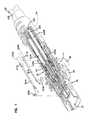
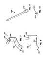
- FIG. 1is a cut-away perspective view of an optical/electrical cable terminated by an optical/electrical connector with the optical/electrical connector connected to an optical/electrical adapter and electrical conductors of the optical/electrical connector and the optical/electrical adapter vertically exploded above the connector and the adapter;
- FIG. 2is the cut-away perspective view of FIG. 1 but with the uncut electrical conductors of FIG. 1 unexploded;
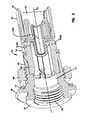
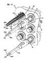
- FIG. 3is a cross-sectional perspective view of the optical/electrical adapter of FIG. 1 with the electrical conductors of the optical/electrical adapter removed;
- FIG. 4is the cross-sectional perspective view of FIG. 3 but with the electrical conductors shown;
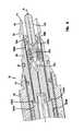
- FIG. 5is a cross-sectional perspective view of the optical/electrical connector of FIG. 1 with the electrical conductors of the optical/electrical connector removed;
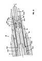
- FIG. 6is the cross-sectional perspective view of FIG. 5 but with the electrical conductors shown;
- FIG. 7is a perspective view of the electrical conductor of the optical/electrical adapter of FIG. 1 ;
- FIG. 8is a side elevation view of the electrical conductor of the optical/electrical adapter of FIG. 1 ;
- FIG. 9is a perspective view of the electrical conductor of the optical/electrical connector of FIG. 1 ;
- FIG. 10is a rear elevation view of the electrical conductor of the optical/electrical connector of FIG. 1 ;
- FIG. 11is a partial perspective view of a cabinet with six of the optical/electrical adapters of FIG. 1 mounted in openings of a cabinet panel of the cabinet and three of the optical/electrical connectors of FIG. 1 connected to three of the adapters and one of the adapter-connector pairs shown in horizontal cross-section;
- FIG. 12is the partial perspective view of FIG. 11 but with only the cabinet panel shown;
- FIG. 13is the partial perspective view of FIG. 11 but with the cabinet panel removed thereby more fully revealing adapter-to-adapter electrical conductors within the cabinet;
- FIG. 14is the partial perspective view of FIG. 11 but with the cabinet panel removed and portions of the adapters and the connectors cut away thereby more fully revealing the adapter-to-adapter electrical conductors of FIG. 13 ;
- FIG. 15is the partial perspective view of FIG. 11 but with only one of the adapter-to-adapter electrical conductors of FIG. 13 shown;
- FIG. 16is the partial perspective view of FIG. 11 but with only another of the adapter-to-adapter electrical conductors of FIG. 13 shown;
- FIG. 17is an enlarged portion of an upper-left corner of FIG. 14 ;
- FIG. 18is the enlarged portion of FIG. 17 but with the optical/electrical connector of FIG. 1 removed;
- FIG. 19is similar to the view of FIG. 14 but with a multi-adapter electrical conductor replacing the adapter-to-adapter electrical conductors of FIG. 13 , only two of the optical/electrical connectors of FIG. 1 inserted into the six optical/electrical adapters of FIG. 1 , three left-side adapters having an inverted orientation, and one of the adapters shown in horizontal cross-section.
- a fiber optic cableincludes at least one optical fiber and at least one electrical conductor.
- the fiber optic cableis terminated and connected to hardware such as telecommunications and/or computer hardware.
- the optical fiberis optically connected and the electrical conductor is electrically connected to the hardware via the termination.
- the hardwarecan include an adapter, and the adapter can connect the fiber optic cable to a second optical cable and/or a second electrical conductor.
- a fiber optic cable 20includes two electrical conductors, 224 A and 224 B.
- the fiber optic cable 20includes a first strength member 224 A and a second strength member 224 B that are electrically conductive and function as the electrical conductors 224 A, 224 B (see FIGS. 1 and 2 ).
- Example strength members 224 A, 224 Bcan be made of aramid yarn, steel, glass-reinforced plastic (GRP), and/or epoxy reinforced glass roving.
- the strength members 224 A, 224 Bcan include a conductive metallic coating such as an aluminum or a copper coating over otherwise non-conducting or poorly conducting material.
- the strength members 224 A, 224 Bcan include conductive metallic strands such as aluminum or copper strands, and the strands can be mixed with otherwise non-conducting or poorly conducting material of the strength members 224 A, 224 B. In other embodiments, the electrical conductors 224 A and 224 B can be separate from the strength members.
- the example fiber optic cable 20further includes an optical fiber 500 , a buffer layer 220 (see FIGS. 5 and 6 ), and a cable jacket 226 .
- the fiber optic cable 20is terminated by a fiber optic connector 32 .
- the fiber optic connector 32can be a ruggedized fiber optic connector and is depicted as such.
- the fiber optic connector 32includes similarities to fiber optic connectors illustrated at U.S. Patent Application Publications 2009/0148101, 2009/0148102, 2009/0148103, and 2009/0148104, incorporated by reference above.
- the fiber optic connector 32includes a connector housing 39 (see FIG. 5 ) that extends between a proximal end 54 (see FIG. 1 ) and a distal end 52 (see FIG. 5 ).
- the distal end 52includes a plug portion 56 , and the proximal end 54 is mechanically connected to the fiber optic cable 20 .
- a coupling nut 40 with external threads 75can be placed over and/or rotatably mounted on the connector housing 39 .
- a sealing member 49can be placed around the connector housing 39 between the coupling nut 40 and the distal end 52 .
- a ferrule 100is mounted to the plug portion 56 and terminates the optical fiber 500 of the fiber optic cable 20 .
- the ferrule 100defines a central longitudinal axis A 1 of the fiber optic connector 32 (see FIGS. 5 and 6 ).
- the fiber optic connector 32includes a first electrical conductor 391 A and a second electrical conductor 391 B.
- the first electrical conductor 391 Ais electrically connected with the first strength member 224 A
- the second electrical conductor 391 Bis electrically connected with the second strength member 224 B (see FIG. 6 ).
- the connector housing 39includes a first pathway 396 A and a second pathway 396 B that extend at least partially within the connector housing 39 (see FIG. 5 ).
- the first and the second pathways 396 A, 396 Bextend within a circumference of the sealing member 49 and thus do not interfere or compromise functionality of the sealing member 49 .
- the first and the second pathways 396 A, 396 Bextend within an interior of the coupling nut 40 and thus do not interfere or compromise functionality of the coupling nut 40 .
- the first and the second pathways 396 A, 396 Bextend within various other features of the connector housing 39 , as illustrated at FIG. 5 .
- the first and the second pathways 396 A, 396 Bdistally emerge at detents 55 A and 55 B of the connector housing 39 respectively, and the pathways 396 A, 396 B proximally emerge within the connector 32 near ends 225 A, 225 B of the strength members 224 A, 224 B.
- the detents 55 A, 55 Bcan be positioned at the plug portion 56 of the connector housing 39 .
- the first electrical conductor 391 Ais positioned partially within the first pathway 396 A
- the second electrical conductor 391 Bis positioned partially within the second pathway 396 B.
- the first electrical conductor 391 A of the fiber optic connector 32includes a contacting portion 381 A at or near its distal end, and the second electrical conductor 391 B of the fiber optic connector 32 includes a contacting portion 381 B at or near its distal end (see FIG. 6 ).
- the contacting portion 381 Ais exposed within the detent 55 A, and the contacting portion 381 B is exposed within the detent 55 B.
- the first electrical conductor 391 A of the fiber optic connector 32includes a lug 371 A at or near its proximal end, and the second electrical conductor 391 B of the fiber optic connector 32 includes a lug 371 B at or near its distal end (see FIGS. 1 and 2 ).
- the lugs 371 A, 371 Bare adapted to be mechanically and electrically connected with the strength members 224 A, 224 B.
- the electrical conductors 391 A, 391 Bthereby electrically connect the strength members 224 B, 224 A to the plug portion 56 of the fiber optic connector 32 .
- the contacting portions 381 A, 381 Bface laterally outward from the plug portion 56 .
- the fiber optic connector 32can be received by and connected to a fiber optic adapter 34 .
- the fiber optic adapter 34can be a ruggedized fiber optic adapter and is depicted as such.
- the fiber optic adapter 34includes similarities to fiber optic adapters illustrated at U.S. Patent Application Publications 2009/0148101, 2009/0148102, 2009/0148103, and 2009/0148104, incorporated by reference above.
- the fiber optic adapter 34includes a housing 44 (see FIG. 3 ) that extends between a first end 70 and a second end 72 .
- the housing 44includes a first housing piece 45 and a second housing piece 47 that snap together.
- the first end 70 of the housing 44includes a port 35
- the second end 72includes a port 37 .
- the port 35is a ruggedized port and the port 37 is a non-ruggedized port.
- the ruggedized port 35includes internal threads 76 and a sealing surface 74 (see FIG. 4 ) that are included in the first housing piece 45 .
- An adapter mounting nut 46can be placed over external threads 66 of the first housing piece 45 of the adapter housing 44 .
- the first housing piece 45can include a mounting flange 48 for use in conjunction with the adapter mounting nut 46 .
- a sealing member 17can be placed around the adapter housing 44 between the adapter mounting nut 46 and the mounting flange 48 .
- Ruggedisation functionsincluding sealing by the sealing member 17 and the sealing surface 74 , adapter 34 mounting by the mounting flange 48 and the mounting nut 46 , and connector 32 attachment by the internal threads 76 are thus accomplished and/or accommodated by the first housing piece 45 of the adapter housing 44 .
- a ferrule holding and alignment sleeve 202is mounted within the fiber optic adapter 34 and is accessible from both the ports 35 and 37 .
- the alignment sleeve 202defines an axis A 2 of the fiber optic adapter 34 .
- the fiber optic adapter 34includes a first electrical conductor 323 A and a second electrical conductor 323 B.
- the first and second electrical conductors 323 A, 323 Bcan be substantially identical to each other and be collectively referred to as an electrical conductor 323 (see FIGS. 7 and 8 ).
- the electrical conductor 323is made of a material with flexible and/or spring-like properties.
- the first electrical conductor 323 Ais electrically connected with the first electrical conductor 391 A and the second electrical conductor 323 B is electrically connected with the second electrical conductor 391 B when the fiber optic connector 32 is fully received by the fiber optic adapter 34 (see FIGS. 1 and 2 ).
- the second housing piece 47 of the adapter housing 44includes a first slot 343 A and a second slot 343 B that extend through a wall 50 of the second housing piece 47 (see FIG. 3 ).
- the first and the second slots 343 A, 343 Bextend through the wall 50 of the second housing piece 47 of the housing 44 between the sealing member 17 and the non-ruggedized port 37 and thus do not interfere or compromise functionality of the sealing member 17 , the sealing surface 74 , and/or other ruggedized features of the ruggedized fiber optic adapter 34 .
- the first and the second slots 343 A, 343 Bextend within an interior of the adapter housing 44 .
- the first electrical conductor 323 Ais positioned partially within the first slot 343 A
- the second electrical conductor 323 Bis positioned partially within the second slot 343 B (see FIGS. 3 and 4 ).
- the first electrical conductor 323 A of the fiber optic adapter 34includes a contacting portion 383 A at or near an exterior of the adapter housing 44
- the second electrical conductor 323 Bincludes a contacting portion 383 B at or near the exterior of the adapter housing 44 (see FIG. 4 ).
- the contacting portions 383 A, 383 Bface normal to the central longitudinal axis A 2 of the fiber optic adapter 34 .
- the first electrical conductor 323 A of the fiber optic adapter 34includes a contact 331 A at or near the interior of the adapter housing 44
- the second electrical conductor 323 Bincludes a contact 331 B at or near the interior of the adapter housing 44 (see FIG. 4 ).
- the contacts 331 A, 331 Bare biased inwardly within the adapter housing 44 and are adapted to be mechanically and electrically connected with the contacting portions 381 A, 381 B of the electrical conductors 391 A, 391 B of the fiber optic connector 32 when the fiber optic connector 32 is fully inserted into the first port 35 of the fiber optic adapter 34 .
- the contacts 331 A, 331 Binclude a ramp and/or a rounded portion 332 (see FIGS. 7 and 8 ).
- the electrical conductor 323includes a cantilevered arm 333 that urges the contacts 331 A, 331 B inward toward the axis A 2 of the fiber optic adapter 34 when the electrical conductors 323 are in an installed position, as shown at FIG. 4 .
- the plug portion 56can flex the contacts 331 A, 331 B of the electrical conductors 323 A, 323 B outward. As the insertion continues, the contacts 331 A, 331 B reach the detents 55 A, 55 B of the connector housing 39 and thereby un-flex into the detents 55 A, 55 B. When the contacts 331 A, 331 B un-flex, they establish electrical contact with the contacting portions 381 A, 381 B of the electrical conductors 391 A, 391 B of the fiber optic connector 32 . The electrical conductors 323 A, 323 B thereby electrically connect the fiber optic connector 32 to the exterior of the fiber optic adapter 34 .
- a path of electrical continuity that respectively includes the strength members 224 A, 224 B of the fiber optic cable 20 , the conductors 391 A, 391 B of the fiber optic connector 32 , and the conductors 323 A, 323 B of the fiber optic adapter 34can continue within a enclosure 19 (e.g., a cabinet, a fiber distribution hub, a drop terminal, etc.) or other piece of optical-electrical hardware (see FIGS. 11 , 13 , 14 , and 17 - 19 ).
- An example drop terminalis described at U.S. Patent Application Publication No. 2008/0138025, published Jun. 12, 2008, and is hereby incorporated by reference in its entirety.
- the enclosure 19includes one or more openings 22 (see FIG.
- An example electrical conductor 260can be included within the enclosure 19 that makes electrical contact with the contacting portions 383 A, 383 B of the electrical conductors 323 A, 323 B (see FIG. 14 ).
- the path of electrical continuitycan transmit electricity for the purpose of electrical power and/or electrical signals between the fiber optic cable 20 and the enclosure 19 .
- the electrical conductor 260can be included on and held by a circuit board 250 or other suitable means.
- FIGS. 11 and 13 - 19illustrate several circuit boards that are collectively referred to as the circuit boards 250 .
- the circuit boards 250include several electrical conductors that are collectively referred to as the electrical conductors 260 .
- the electrical conductors 323include a valley 328 and a peak 329 .
- the circuit boards 250can be held in operational position by mounting them on one or more of the electrical conductors 323 .
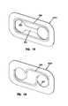
- the circuit boards 250include one or more openings 222 (see FIGS. 15 and 16 ).
- the openings 222 of the circuit boards 250can be held within a pair of opposed valleys 328 of the electrical conductors 323 of the fiber optic adapters 34 .
- the circuit boards 250can be snapped on and snapped off from around the fiber optic adapters 34 by pressing them over the peaks 329 of the electrical conductors 323 of the fiber optic adapters 34 .
- the peaks 329can elastically and/or plastically deform when the circuit board 250 is snapped on and off.
- the circuit boards 250 or other mountings for the electrical conductors 260 within the enclosure 19can be mechanically supported by the enclosure 19 and/or other structure within the enclosure 19 . This allows the electrical conductors 323 of the adapter 34 to be electrically connected with the conductors 260 of the circuit board 250 when the adapter 34 is inserted through the opening 22 of the enclosure 19 . As described above but with the circuit board 250 remaining stationary, the adapter 34 can be snapped in and snapped out of the opening 222 of the circuit board 250 .
- FIGS. 11 and 13 - 19illustrate the various circuit boards 250 .
- FIGS. 11 and 13 - 18illustrate a crossed connection circuit board 250 C and a straight connection circuit board 250 S.
- the circuit boards 250 C and 250 Scan transmit signals and/or power between a first fiber optic cable 20 A and a second fiber optic cable 20 B.
- the crossed connection circuit board 250 Cresults in electrical connection between the first strength member 224 A of the first fiber optic cable 20 A and the second strength member 224 B of the second fiber optic cable 20 B.
- the crossed connection circuit board 250 Calso results in electrical connection between the second strength member 224 B of the first fiber optic cable 20 A and the first strength member 224 A of the second fiber optic cable 20 B (see FIG. 13 ).
- the straight connection circuit board 250 Sresults in electrical connection between the first strength member 224 A of the first fiber optic cable 20 A and the first strength member 224 A of the second fiber optic cable 20 B.
- the straight connection circuit board 250 Salso results in electrical connection between the second strength member 224 B of the first fiber optic cable 20 A and the second strength member 224 B of the second fiber optic cable 20 B.
- the circuit boards 250 C and 250 S and the paths of electrical continuity that they are part ofcan be used, for example, to bring electrical power from a dwelling of an end user to a fiber optic enclosure (e.g., the cabinet, the fiber distribution hub, the drop terminal, etc.).
- the electrical powercan be transferred by the fiber optic cables 20 A, 20 B and used within the fiber optic enclosure to provide power to active optical components within the enclosure.
- One of the cables 20 A, 20 Bcan be connected to the dwelling of the end user and receive electrical power from the dwelling.
- FIG. 19illustrates a circuit board 250 P that includes an electrical plug 252 .
- the circuit board 250 P and the paths of electrical continuity that it is a part ofcan be used, for example, to bring electrical power from a power supply within a fiber optic enclosure to one or more of the fiber optic cables 20 that are connected to the fiber optic enclosure.
- the circuit board 250 P and the paths of electrical continuitycan be used to transmit an electrical signal to, from, and/or through the fiber optic enclosure that mounts the circuit board 250 P.
Landscapes
- Physics & Mathematics (AREA)
- General Physics & Mathematics (AREA)
- Optics & Photonics (AREA)
- Mechanical Coupling Of Light Guides (AREA)
- Connector Housings Or Holding Contact Members (AREA)
- Light Guides In General And Applications Therefor (AREA)
Abstract
Description
Claims (20)
Priority Applications (10)
| Application Number | Priority Date | Filing Date | Title |
|---|---|---|---|
| US13/021,416US8480312B2 (en) | 2010-02-04 | 2011-02-04 | Ruggedized fiber optic/electrical connection system |
| US13/936,499US8894300B2 (en) | 2010-02-04 | 2013-07-08 | Ruggedized fiber optic/electrical connection system |
| US14/552,210US9104001B2 (en) | 2007-12-11 | 2014-11-24 | Ruggedized fiber optic/electrical connection system |
| US14/822,170US9459411B2 (en) | 2007-12-11 | 2015-08-10 | Ruggedized fiber optic/electrical connector |
| US15/282,165US9989707B2 (en) | 2007-12-11 | 2016-09-30 | Enclosure for fiber optic/electrical system |
| US15/996,962US10345531B2 (en) | 2010-02-04 | 2018-06-04 | Fiber optic/electrical connection system |
| US16/421,545US10838151B2 (en) | 2010-02-04 | 2019-05-24 | Fiber optic/electrical connection system |
| US17/068,911US11500161B2 (en) | 2010-02-04 | 2020-10-13 | Fiber optic/electrical connection system |
| US17/970,048US11860424B2 (en) | 2010-02-04 | 2022-10-20 | Fiber optic/electrical connection system |
| US18/389,306US12271037B2 (en) | 2010-02-04 | 2023-11-14 | Fiber optic/electrical connection system |
Applications Claiming Priority (2)
| Application Number | Priority Date | Filing Date | Title |
|---|---|---|---|
| US30146010P | 2010-02-04 | 2010-02-04 | |
| US13/021,416US8480312B2 (en) | 2010-02-04 | 2011-02-04 | Ruggedized fiber optic/electrical connection system |
Related Child Applications (1)
| Application Number | Title | Priority Date | Filing Date |
|---|---|---|---|
| US13/936,499ContinuationUS8894300B2 (en) | 2007-12-11 | 2013-07-08 | Ruggedized fiber optic/electrical connection system |
Publications (2)
| Publication Number | Publication Date |
|---|---|
| US20110200286A1 US20110200286A1 (en) | 2011-08-18 |
| US8480312B2true US8480312B2 (en) | 2013-07-09 |
Family
ID=44356086
Family Applications (10)
| Application Number | Title | Priority Date | Filing Date |
|---|---|---|---|
| US13/021,416Expired - Fee RelatedUS8480312B2 (en) | 2007-12-11 | 2011-02-04 | Ruggedized fiber optic/electrical connection system |
| US13/936,499ActiveUS8894300B2 (en) | 2007-12-11 | 2013-07-08 | Ruggedized fiber optic/electrical connection system |
| US14/552,210ActiveUS9104001B2 (en) | 2007-12-11 | 2014-11-24 | Ruggedized fiber optic/electrical connection system |
| US14/822,170ActiveUS9459411B2 (en) | 2007-12-11 | 2015-08-10 | Ruggedized fiber optic/electrical connector |
| US15/282,165ActiveUS9989707B2 (en) | 2007-12-11 | 2016-09-30 | Enclosure for fiber optic/electrical system |
| US15/996,962ActiveUS10345531B2 (en) | 2010-02-04 | 2018-06-04 | Fiber optic/electrical connection system |
| US16/421,545ActiveUS10838151B2 (en) | 2010-02-04 | 2019-05-24 | Fiber optic/electrical connection system |
| US17/068,911Active2031-04-25US11500161B2 (en) | 2010-02-04 | 2020-10-13 | Fiber optic/electrical connection system |
| US17/970,048ActiveUS11860424B2 (en) | 2010-02-04 | 2022-10-20 | Fiber optic/electrical connection system |
| US18/389,306ActiveUS12271037B2 (en) | 2010-02-04 | 2023-11-14 | Fiber optic/electrical connection system |
Family Applications After (9)
| Application Number | Title | Priority Date | Filing Date |
|---|---|---|---|
| US13/936,499ActiveUS8894300B2 (en) | 2007-12-11 | 2013-07-08 | Ruggedized fiber optic/electrical connection system |
| US14/552,210ActiveUS9104001B2 (en) | 2007-12-11 | 2014-11-24 | Ruggedized fiber optic/electrical connection system |
| US14/822,170ActiveUS9459411B2 (en) | 2007-12-11 | 2015-08-10 | Ruggedized fiber optic/electrical connector |
| US15/282,165ActiveUS9989707B2 (en) | 2007-12-11 | 2016-09-30 | Enclosure for fiber optic/electrical system |
| US15/996,962ActiveUS10345531B2 (en) | 2010-02-04 | 2018-06-04 | Fiber optic/electrical connection system |
| US16/421,545ActiveUS10838151B2 (en) | 2010-02-04 | 2019-05-24 | Fiber optic/electrical connection system |
| US17/068,911Active2031-04-25US11500161B2 (en) | 2010-02-04 | 2020-10-13 | Fiber optic/electrical connection system |
| US17/970,048ActiveUS11860424B2 (en) | 2010-02-04 | 2022-10-20 | Fiber optic/electrical connection system |
| US18/389,306ActiveUS12271037B2 (en) | 2010-02-04 | 2023-11-14 | Fiber optic/electrical connection system |
Country Status (6)
| Country | Link |
|---|---|
| US (10) | US8480312B2 (en) |
| EP (2) | EP3584615A1 (en) |
| CN (2) | CN104536099B (en) |
| AU (3) | AU2011212790B2 (en) |
| ES (1) | ES2755911T3 (en) |
| WO (1) | WO2011097473A2 (en) |
Cited By (47)
| Publication number | Priority date | Publication date | Assignee | Title |
|---|---|---|---|---|
| US20110188810A1 (en)* | 2010-01-29 | 2011-08-04 | Ciechomski Tomasz A | Hybrid connector |
| US20130129285A1 (en)* | 2011-11-21 | 2013-05-23 | Min Dong | Optical fiber connector, optical fiber adapter, and waterproof optical fiber assembly using the same |
| US8794852B2 (en) | 2010-03-10 | 2014-08-05 | Corning Cable Systems Llc | Hybrid fiber optic pigtail assembly |
| US8842962B2 (en) | 2012-01-27 | 2014-09-23 | Corning Cable Systems Llc | Fiber optic cable strain relief device and method |
| US8894300B2 (en) | 2010-02-04 | 2014-11-25 | Adc Telecommunications, Inc. | Ruggedized fiber optic/electrical connection system |
| US20150043870A1 (en)* | 2011-02-17 | 2015-02-12 | Tyco Electronics Services Gmbh | Fiber-optic connection arrangement and adapter sleeve |
| US9052468B2 (en) | 2011-03-04 | 2015-06-09 | Corning Cable Systems Llc | Fiber optic adapter mount |
| US9110266B2 (en) | 2011-07-29 | 2015-08-18 | Corning Cable Systems Llc | Fiber optic cables seal and/or strain relief members, and related assemblies and methods |
| US9110267B2 (en) | 2012-10-26 | 2015-08-18 | Ccs Technology, Inc. | Strain relief device for cables and fiber optic distribution device |
| US9472314B2 (en) | 2013-05-14 | 2016-10-18 | Commscope Technologies Llc | Power/fiber hybrid cable |
| US9488793B2 (en) | 2013-09-10 | 2016-11-08 | Corning Optical Communications LLC | Combined optical fiber and power cable |
| US9557505B2 (en) | 2013-03-18 | 2017-01-31 | Commscope Technologies Llc | Power and optical fiber interface |
| US9893811B2 (en) | 2013-03-18 | 2018-02-13 | Commscope Technologies Llc | Architecture for a wireless network |
| US9927580B2 (en) | 2014-02-07 | 2018-03-27 | Commscope Technologies Llc | Hardened optical power connection system |
| US10061090B2 (en) | 2014-03-28 | 2018-08-28 | CommScope Connectivity Belgium BVBA | Fiber optic connection system |
| US10295771B2 (en) | 2016-05-03 | 2019-05-21 | Corning Optical Communications LLC | Telecommunications terminal with removable modules |
| US10401574B2 (en) | 2015-01-26 | 2019-09-03 | Commscope Technologies Llc | Hybrid fiber power connection system |
| US10591678B2 (en)* | 2012-11-30 | 2020-03-17 | Commscope Technologies Llc | Fiber optic connector with field installable outer connector housing |
| US10732358B2 (en)* | 2016-11-09 | 2020-08-04 | Commscope Technologies Llc | Electrical-polarity switching hybrid interface |
| WO2021051204A1 (en)* | 2019-09-20 | 2021-03-25 | Photon Control Inc. | Calibration system for fiber optic temperature probe |
| US10976500B2 (en) | 2015-12-16 | 2021-04-13 | Commscope Technologies Llc | Field installed fiber optic connector |
| US11002917B2 (en) | 2014-02-14 | 2021-05-11 | Commscope Telecommunications (Shanghai) Co. Ltd. | Fiber optic connector and method of assembling the same |
| US11119546B2 (en) | 2016-11-09 | 2021-09-14 | Commscope, Inc. Of North Carolina | Exchangeable powered infrastructure module |
| US11119283B2 (en) | 2014-07-09 | 2021-09-14 | Commscope Telecommunications (Shanghai) Co. Ltd. | Optical fiber connector and method of assembling the same on site |
| US11187859B2 (en) | 2017-06-28 | 2021-11-30 | Corning Research & Development Corporation | Fiber optic connectors and methods of making the same |
| US11215768B2 (en) | 2017-06-28 | 2022-01-04 | Corning Research & Development Corporation | Fiber optic connectors and connectorization employing adhesive admitting adapters |
| US11294133B2 (en) | 2019-07-31 | 2022-04-05 | Corning Research & Development Corporation | Fiber optic networks using multiports and cable assemblies with cable-to-connector orientation |
| US11300746B2 (en) | 2017-06-28 | 2022-04-12 | Corning Research & Development Corporation | Fiber optic port module inserts, assemblies and methods of making the same |
| US20220187554A1 (en)* | 2019-06-25 | 2022-06-16 | Japan Aviation Electronics Industry, Limited | Plug connector |
| US11372182B2 (en)* | 2018-08-31 | 2022-06-28 | Synergia Medical | Optical fibres connector for optoelectronic active implantable medical device (AIMD) |
| US11409051B2 (en) | 2015-11-30 | 2022-08-09 | Commscope Technologies Llc | Fiber optic connector and assembly thereof |
| US11474306B2 (en) | 2014-02-14 | 2022-10-18 | Commscope Telecommunications (Shanghai) Co. Ltd. | Fiber optic connector and method of assembling the same |
| US11487073B2 (en) | 2019-09-30 | 2022-11-01 | Corning Research & Development Corporation | Cable input devices having an integrated locking feature and assemblies using the cable input devices |
| US11536921B2 (en) | 2020-02-11 | 2022-12-27 | Corning Research & Development Corporation | Fiber optic terminals having one or more loopback assemblies |
| US11604320B2 (en) | 2020-09-30 | 2023-03-14 | Corning Research & Development Corporation | Connector assemblies for telecommunication enclosures |
| US11650388B2 (en) | 2019-11-14 | 2023-05-16 | Corning Research & Development Corporation | Fiber optic networks having a self-supporting optical terminal and methods of installing the optical terminal |
| US11668890B2 (en) | 2017-06-28 | 2023-06-06 | Corning Research & Development Corporation | Multiports and other devices having optical connection ports with securing features and methods of making the same |
| US11686913B2 (en) | 2020-11-30 | 2023-06-27 | Corning Research & Development Corporation | Fiber optic cable assemblies and connector assemblies having a crimp ring and crimp body and methods of fabricating the same |
| US11703646B2 (en) | 2017-06-28 | 2023-07-18 | Corning Research & Development Corporation | Multiports and optical connectors with rotationally discrete locking and keying features |
| US11880076B2 (en) | 2020-11-30 | 2024-01-23 | Corning Research & Development Corporation | Fiber optic adapter assemblies including a conversion housing and a release housing |
| US11886010B2 (en) | 2019-10-07 | 2024-01-30 | Corning Research & Development Corporation | Fiber optic terminals and fiber optic networks having variable ratio couplers |
| US11927810B2 (en) | 2020-11-30 | 2024-03-12 | Corning Research & Development Corporation | Fiber optic adapter assemblies including a conversion housing and a release member |
| US11947167B2 (en) | 2021-05-26 | 2024-04-02 | Corning Research & Development Corporation | Fiber optic terminals and tools and methods for adjusting a split ratio of a fiber optic terminal |
| US11994722B2 (en) | 2020-11-30 | 2024-05-28 | Corning Research & Development Corporation | Fiber optic adapter assemblies including an adapter housing and a locking housing |
| US12019279B2 (en) | 2019-05-31 | 2024-06-25 | Corning Research & Development Corporation | Multiports and other devices having optical connection ports with sliding actuators and methods of making the same |
| US12271040B2 (en) | 2017-06-28 | 2025-04-08 | Corning Research & Development Corporation | Fiber optic extender ports, assemblies and methods of making the same |
| US12372727B2 (en) | 2020-10-30 | 2025-07-29 | Corning Research & Development Corporation | Female fiber optic connectors having a rocker latch arm and methods of making the same |
Families Citing this family (25)
| Publication number | Priority date | Publication date | Assignee | Title |
|---|---|---|---|---|
| US8942528B2 (en)* | 2012-01-10 | 2015-01-27 | Corning Cable Systems Llc | Fiber optic cable sub-assemblies and methods of assembling |
| US20130343707A1 (en)* | 2012-06-26 | 2013-12-26 | General Cable Technologies Corporation | Cable and connector adapter assembly |
| US10958348B2 (en)* | 2012-12-29 | 2021-03-23 | Zephyr Photonics Inc. | Method for manufacturing modular multi-function active optical cables |
| US9739962B2 (en)* | 2013-05-14 | 2017-08-22 | Vixar | Plastic optical fiber data communication links |
| TWI486657B (en)* | 2013-07-10 | 2015-06-01 | Advanced Connetek Inc | Optic fiber connector |
| US9977198B2 (en) | 2013-07-16 | 2018-05-22 | 3M Innovative Properties Company | High retention force optical coupling |
| CA2916720A1 (en) | 2013-07-16 | 2015-04-02 | 3M Innovative Properties Company | Connector for telecommunication enclosures |
| CN104656200A (en)* | 2013-11-20 | 2015-05-27 | 鸿富锦精密工业(深圳)有限公司 | Optical fiber connector |
| WO2016063135A2 (en) | 2014-10-20 | 2016-04-28 | Commscope Emea Limited | Hybrid copper/fiber connector, systems and methods |
| CA2971584C (en)* | 2014-12-19 | 2023-08-01 | 3M Innovative Properties Company | Ruggedized optical fiber connection structures and assemblies |
| US10768374B2 (en) | 2015-01-26 | 2020-09-08 | Commscope Technologies Llc | Indoor hybrid connectivity system for providing both electrical power and fiber optic service |
| US10551309B2 (en) | 2016-07-22 | 2020-02-04 | Comodo Security Solutions, Inc. | Method and system to improve scheme of optical network cable and audio cable |
| EP3776037B1 (en) | 2018-04-03 | 2024-11-27 | Corning Research & Development Corporation | Hermaphroditic hybrid optical cables and connectors |
| US20200225426A1 (en)* | 2018-08-03 | 2020-07-16 | Ppc Broadband, Inc. | Fiber Optical Connectors |
| US11435534B2 (en)* | 2019-06-11 | 2022-09-06 | Clearfield, Inc. | Flexible optical fiber connectors and assemblies |
| CN114174878B (en)* | 2019-07-29 | 2024-07-30 | 巴德阿克塞斯系统股份有限公司 | Connection system and method for establishing optical and electrical connections through a drape |
| MX2022002410A (en)* | 2019-08-26 | 2022-05-13 | Commscope Technologies Llc | FIBER OPTICAL CONNECTORS AND FIBER OPTICAL CONNECTION SYSTEMS. |
| CN111025490B (en)* | 2019-12-18 | 2021-11-19 | 华为技术有限公司 | Photoelectric composite connector and photoelectric adapter |
| CN111106469B (en) | 2019-12-20 | 2021-05-07 | 华为技术有限公司 | Connector assembly and photoelectric composite connector |
| WO2022003390A1 (en)* | 2020-06-29 | 2022-01-06 | Tarvij Sanat Sumi Parsian Co. | Apparatus for simultaneously transmitting data and electrical power |
| US20230123261A1 (en)* | 2021-10-17 | 2023-04-20 | Senko Advanced Components, Inc. | Fiber optic connector |
| US12009117B2 (en)* | 2022-05-16 | 2024-06-11 | Panduit Corp. | Hybrid fiber optic and electrical connector |
| US12332483B2 (en)* | 2022-06-02 | 2025-06-17 | Globalfoundries U.S. Inc. | Photonics structures with stacked ring resonators |
| EP4300151A1 (en)* | 2022-06-30 | 2024-01-03 | Ortronics, Inc. | Hybrid fiber connector |
| CN219831444U (en)* | 2023-02-03 | 2023-10-13 | 华为技术有限公司 | Optical fiber connectors, connector components and optical communication equipment |
Citations (40)
| Publication number | Priority date | Publication date | Assignee | Title |
|---|---|---|---|---|
| US4373777A (en) | 1980-08-11 | 1983-02-15 | International Telephone And Telegraph Corporation | Connector and cable assembly |
| US4449784A (en) | 1981-06-22 | 1984-05-22 | Trw Inc. | Hybrid optical/electrical connector |
| US4896939A (en) | 1987-10-30 | 1990-01-30 | D. G. O'brien, Inc. | Hybrid fiber optic/electrical cable and connector |
| US5159651A (en) | 1991-11-25 | 1992-10-27 | The Rochester Corporation | Electro-optical connector assembly |
| US5267337A (en) | 1991-06-03 | 1993-11-30 | Deutsche Aerospace Airbus Gmbh | Combined connector for coupling electrical conductors and optical conductors respectively |
| US5345520A (en) | 1993-07-28 | 1994-09-06 | Grile Mark E | Electrical connector with an optical fiber connection detector |
| US5461688A (en) | 1994-09-02 | 1995-10-24 | Augat Inc. | Fiber optic connector with electrical contact |
| US5467420A (en) | 1993-04-10 | 1995-11-14 | Kabel Rheydt Aktiengesellschaft | Coaxial high frequency cable including an optical fiber element |
| US5473715A (en) | 1994-05-03 | 1995-12-05 | Methode Electronics, Inc. | Hybrid fiber optic/electrical connector |
| US5574815A (en) | 1991-01-28 | 1996-11-12 | Kneeland; Foster C. | Combination cable capable of simultaneous transmission of electrical signals in the radio and microwave frequency range and optical communication signals |
| US6416334B1 (en) | 2000-03-24 | 2002-07-09 | Paul J. Plishner | Combination multi-conductor/optical fiber connector |
| US6542674B1 (en) | 2000-08-25 | 2003-04-01 | Corning Cable Systems Llc | Fiber optic cables with strength members |
| US6546175B1 (en) | 2000-05-26 | 2003-04-08 | Corning Cable Systems Llc | Self-supporting fiber optic cable |
| US6579014B2 (en) | 2001-09-28 | 2003-06-17 | Corning Cable Systems Llc | Fiber optic receptacle |
| US6588938B1 (en) | 2000-10-18 | 2003-07-08 | Fitel Usa Corp. | Optical/electrical plug connector |
| US6648520B2 (en) | 2001-09-28 | 2003-11-18 | Corning Cable Systems Llc | Fiber optic plug |
| US20040050314A1 (en) | 2002-09-12 | 2004-03-18 | Williams Michael R. | Tow cable termination assembly |
| US6733186B2 (en) | 2001-09-27 | 2004-05-11 | Siemens Information & Communication Networks, Inc. | Optical connection verification apparatus and method |
| US6931183B2 (en) | 1996-03-29 | 2005-08-16 | Dominion Lasercom, Inc. | Hybrid electro-optic cable for free space laser antennas |
| US7018331B2 (en) | 1996-08-26 | 2006-03-28 | Stryker Corporation | Endoscope assembly useful with a scope-sensing light cable |
| US7090406B2 (en) | 2000-05-26 | 2006-08-15 | Corning Cable Systems Llc | Preconnectorized fiber optic drop cables and assemblies |
| US7090407B2 (en) | 2000-05-26 | 2006-08-15 | Corning Cable Systems Llc | Preconnectorized fiber optic drop cables and assemblies for efficient deployment |
| US7111990B2 (en) | 2000-05-26 | 2006-09-26 | Corning Cable Systems, Llc | Figure-eight preconnectorized fiber optic drop cables and assemblies |
| US7113679B2 (en) | 2000-05-26 | 2006-09-26 | Corning Cable Systems, Llc | Fiber optic drop cables and preconnectorized assemblies having toning portions |
| US7213975B2 (en) | 2004-09-10 | 2007-05-08 | Adc Telecommunications, Inc. | Hybrid fiber/copper connector system and method |
| US20070160327A1 (en) | 2005-03-10 | 2007-07-12 | Lewallen Christopher P | Multi-fiber fiber optic receptacle and plug assembly |
| US7264402B2 (en) | 2005-03-10 | 2007-09-04 | Corning Cable Systems Llc | Multi-fiber optic receptacle and plug assembly |
| US20080138025A1 (en) | 2004-11-03 | 2008-06-12 | Fiber Optics Network Solutions Corporation | Fiber Drop Terminal |
| US7463803B2 (en) | 2005-11-14 | 2008-12-09 | Corning Cable Systems Llc | Drop cable with fiber optic connector and methods for fabricating same |
| US7481585B2 (en) | 2006-11-29 | 2009-01-27 | Adc Telecommunications, Inc. | Hybrid fiber/copper connector system and method |
| US20090148103A1 (en) | 2007-12-11 | 2009-06-11 | Yu Lu | Hardened Fiber Optic Connector and Cable Assembly with Multiple Configurations |
| US7572065B2 (en) | 2007-01-24 | 2009-08-11 | Adc Telecommunications, Inc. | Hardened fiber optic connector |
| US20090304335A1 (en) | 2008-04-21 | 2009-12-10 | Adc Telecommunications, Inc. | Hardened Fiber Optic Connector with Connector Body Joined to Cylindrical Cable by Unitary Housing |
| US7677813B2 (en) | 2007-06-15 | 2010-03-16 | Trumpf Laser Marking Systems Ag | Electro-optical hybrid connection assembly |
| US7798725B2 (en) | 2005-04-15 | 2010-09-21 | Adc Telecommunications, Inc. | Hybrid fiber/copper connector system and method |
| US20110123157A1 (en)* | 2009-11-24 | 2011-05-26 | Amphenol Corporation | Outdoor transceiver connector |
| US20110200286A1 (en)* | 2010-02-04 | 2011-08-18 | Adc Telecommunications, Inc. | Ruggedized Fiber Optic/Electrical Connection System |
| US8083416B2 (en) | 2007-11-30 | 2011-12-27 | Adc Telecommunications, Inc. | Hybrid fiber/copper connector system and method |
| US8113720B2 (en) | 2006-11-29 | 2012-02-14 | Adc Telecommunications, Inc. | Hybrid fiber/copper connector system and method |
| USRE43542E1 (en) | 2000-06-12 | 2012-07-24 | Adc Gmbh | Assembly and method for use in terminating an optical fiber or fibers |
Family Cites Families (31)
| Publication number | Priority date | Publication date | Assignee | Title |
|---|---|---|---|---|
| JPS6270805A (en) | 1985-09-25 | 1987-04-01 | Furukawa Electric Co Ltd:The | Optical/metal composite cable terminal section |
| US5234353A (en) | 1992-03-03 | 1993-08-10 | Amp Incorporated | Hybrid input/output connector having low mating force and high cycle life and contacts therefor |
| MY111510A (en)* | 1993-03-01 | 2000-07-31 | Lindab Ab | Kit and method for producing a connector for fluid-conducting elements |
| US5419717A (en) | 1994-08-15 | 1995-05-30 | The Whitaker Corporation | Hybrid connector between optics and edge card |
| US5883995A (en)* | 1997-05-20 | 1999-03-16 | Adc Telecommunications, Inc. | Fiber connector and adapter |
| JP3958891B2 (en)* | 1999-04-23 | 2007-08-15 | 矢崎総業株式会社 | Optical connector |
| EP1094355A1 (en)* | 1999-10-19 | 2001-04-25 | Corning Incorporated | Electrical interconnection of planar lightwave circuits |
| US7467896B2 (en) | 2000-05-26 | 2008-12-23 | Corning Cable Systems Llc | Fiber optic drop cables and preconnectorized assemblies |
| CN2452156Y (en)* | 2000-11-02 | 2001-10-03 | 富士康(昆山)电脑接插件有限公司 | Electrooptical connector assembly |
| JP4006191B2 (en)* | 2001-05-14 | 2007-11-14 | 大日本スクリーン製造株式会社 | Optical fiber coupling equipment |
| US6962445B2 (en)* | 2003-09-08 | 2005-11-08 | Adc Telecommunications, Inc. | Ruggedized fiber optic connection |
| US20060045428A1 (en)* | 2004-08-24 | 2006-03-02 | Thomas Theuerkorn | Fiber optic receptacle and plug assemblies |
| CN2733387Y (en)* | 2004-08-31 | 2005-10-12 | 网技科技股份有限公司 | Improvement of Male Seat Structure of Optical Fiber Connector |
| US20060263011A1 (en)* | 2005-05-20 | 2006-11-23 | Wenzong Chen | Hybrid optical/electrical connector and adapter |
| US7572063B2 (en)* | 2005-09-12 | 2009-08-11 | Stratos International, Inc. | Opto-electric connector |
| EP1783521B1 (en) | 2005-11-02 | 2008-05-28 | TKM Telekommunikation und Elektronik GmbH | Connector and RJ-45 connexion system. |
| US7686860B2 (en)* | 2006-03-22 | 2010-03-30 | Drawervac, Llc | Debris receiver |
| EP1986028A3 (en)* | 2007-03-27 | 2008-11-05 | Rohm and Haas Electronic Materials LLC | Optical assemblies and their methods of formation |
| US7686519B2 (en)* | 2007-06-18 | 2010-03-30 | Adc Telecommunications, Inc. | Hardened fiber optic housing and cable assembly |
| US7848604B2 (en)* | 2007-08-31 | 2010-12-07 | Tensolite, Llc | Fiber-optic cable and method of manufacture |
| ES2391486T3 (en) | 2008-11-25 | 2012-11-27 | Ccs Technology Inc. | Hybrid connector |
| US8467654B2 (en) | 2010-04-05 | 2013-06-18 | Avago Technologies General Ip (Singapore) Pte. Ltd. | Modular connector assembly configured with both optical and electrical connections for providing both optical and electrical communications capabilities, and a system that incorporates the assembly |
| US8376630B2 (en) | 2010-04-05 | 2013-02-19 | Avago Technologies Fiber Ip (Singapore) Pte. Ltd. | Hybrid 8P8C RJ-45 modular plug configured with both optical and electrical connections for providing both optical and electrical communications capabilities, and a method |
| CN102801027B (en) | 2011-05-27 | 2016-06-08 | 富士康(昆山)电脑接插件有限公司 | Cable connector combination |
| CN103123408B (en)* | 2011-11-21 | 2015-04-15 | 鸿富锦精密工业(深圳)有限公司 | Waterproof optical fiber connector and optical fiber plug and optical fiber adapter thereof |
| US8842962B2 (en)* | 2012-01-27 | 2014-09-23 | Corning Cable Systems Llc | Fiber optic cable strain relief device and method |
| US8858090B2 (en)* | 2012-06-05 | 2014-10-14 | Corning Cable Systems Llc | Ferrule holders with an integral lead-in tube employed in fiber optic connector assemblies, and related components, connectors, and methods |
| CN203117468U (en) | 2013-02-18 | 2013-08-07 | 中兴通讯股份有限公司 | Optical fiber connector assembly, optical fiber connector plug and adapter assembly |
| WO2014126975A1 (en) | 2013-02-18 | 2014-08-21 | Adc Telecommunications, Inc. | Hybrid power and optical fiber cable with conductive buffer tube |
| WO2019081763A1 (en)* | 2017-10-27 | 2019-05-02 | CommScope Connectivity Belgium BVBA | Cable attachment system |
| US11428886B2 (en)* | 2018-04-23 | 2022-08-30 | Commscope Technologies, Inc. | Mounting bracket system for telecommunications equipment |
- 2011
- 2011-02-04EPEP19191022.3Apatent/EP3584615A1/ennot_activeWithdrawn
- 2011-02-04AUAU2011212790Apatent/AU2011212790B2/ennot_activeCeased
- 2011-02-04USUS13/021,416patent/US8480312B2/ennot_activeExpired - Fee Related
- 2011-02-04EPEP11740419.4Apatent/EP2531878B1/enactiveActive
- 2011-02-04ESES11740419Tpatent/ES2755911T3/enactiveActive
- 2011-02-04CNCN201510047141.3Apatent/CN104536099B/enactiveActive
- 2011-02-04CNCN201180012408.5Apatent/CN102782549B/ennot_activeExpired - Fee Related
- 2011-02-04WOPCT/US2011/023736patent/WO2011097473A2/enactiveApplication Filing
- 2013
- 2013-07-08USUS13/936,499patent/US8894300B2/enactiveActive
- 2014
- 2014-11-24USUS14/552,210patent/US9104001B2/enactiveActive
- 2015
- 2015-08-10USUS14/822,170patent/US9459411B2/enactiveActive
- 2015-10-28AUAU2015249108Apatent/AU2015249108A1/ennot_activeAbandoned
- 2016
- 2016-09-30USUS15/282,165patent/US9989707B2/enactiveActive
- 2018
- 2018-03-02AUAU2018201543Apatent/AU2018201543B2/enactiveActive
- 2018-06-04USUS15/996,962patent/US10345531B2/enactiveActive
- 2019
- 2019-05-24USUS16/421,545patent/US10838151B2/enactiveActive
- 2020
- 2020-10-13USUS17/068,911patent/US11500161B2/enactiveActive
- 2022
- 2022-10-20USUS17/970,048patent/US11860424B2/enactiveActive
- 2023
- 2023-11-14USUS18/389,306patent/US12271037B2/enactiveActive
Patent Citations (55)
| Publication number | Priority date | Publication date | Assignee | Title |
|---|---|---|---|---|
| US4373777A (en) | 1980-08-11 | 1983-02-15 | International Telephone And Telegraph Corporation | Connector and cable assembly |
| US4449784A (en) | 1981-06-22 | 1984-05-22 | Trw Inc. | Hybrid optical/electrical connector |
| US4896939A (en) | 1987-10-30 | 1990-01-30 | D. G. O'brien, Inc. | Hybrid fiber optic/electrical cable and connector |
| US5574815A (en) | 1991-01-28 | 1996-11-12 | Kneeland; Foster C. | Combination cable capable of simultaneous transmission of electrical signals in the radio and microwave frequency range and optical communication signals |
| US5267337A (en) | 1991-06-03 | 1993-11-30 | Deutsche Aerospace Airbus Gmbh | Combined connector for coupling electrical conductors and optical conductors respectively |
| US5159651A (en) | 1991-11-25 | 1992-10-27 | The Rochester Corporation | Electro-optical connector assembly |
| US5467420A (en) | 1993-04-10 | 1995-11-14 | Kabel Rheydt Aktiengesellschaft | Coaxial high frequency cable including an optical fiber element |
| US5345520A (en) | 1993-07-28 | 1994-09-06 | Grile Mark E | Electrical connector with an optical fiber connection detector |
| US5473715A (en) | 1994-05-03 | 1995-12-05 | Methode Electronics, Inc. | Hybrid fiber optic/electrical connector |
| US5461688A (en) | 1994-09-02 | 1995-10-24 | Augat Inc. | Fiber optic connector with electrical contact |
| US6931183B2 (en) | 1996-03-29 | 2005-08-16 | Dominion Lasercom, Inc. | Hybrid electro-optic cable for free space laser antennas |
| US7018331B2 (en) | 1996-08-26 | 2006-03-28 | Stryker Corporation | Endoscope assembly useful with a scope-sensing light cable |
| US6416334B1 (en) | 2000-03-24 | 2002-07-09 | Paul J. Plishner | Combination multi-conductor/optical fiber connector |
| US6546175B1 (en) | 2000-05-26 | 2003-04-08 | Corning Cable Systems Llc | Self-supporting fiber optic cable |
| US7090406B2 (en) | 2000-05-26 | 2006-08-15 | Corning Cable Systems Llc | Preconnectorized fiber optic drop cables and assemblies |
| US7113679B2 (en) | 2000-05-26 | 2006-09-26 | Corning Cable Systems, Llc | Fiber optic drop cables and preconnectorized assemblies having toning portions |
| US7111990B2 (en) | 2000-05-26 | 2006-09-26 | Corning Cable Systems, Llc | Figure-eight preconnectorized fiber optic drop cables and assemblies |
| US7090407B2 (en) | 2000-05-26 | 2006-08-15 | Corning Cable Systems Llc | Preconnectorized fiber optic drop cables and assemblies for efficient deployment |
| USRE43542E1 (en) | 2000-06-12 | 2012-07-24 | Adc Gmbh | Assembly and method for use in terminating an optical fiber or fibers |
| US6542674B1 (en) | 2000-08-25 | 2003-04-01 | Corning Cable Systems Llc | Fiber optic cables with strength members |
| US6588938B1 (en) | 2000-10-18 | 2003-07-08 | Fitel Usa Corp. | Optical/electrical plug connector |
| US6733186B2 (en) | 2001-09-27 | 2004-05-11 | Siemens Information & Communication Networks, Inc. | Optical connection verification apparatus and method |
| US6579014B2 (en) | 2001-09-28 | 2003-06-17 | Corning Cable Systems Llc | Fiber optic receptacle |
| US6899467B2 (en) | 2001-09-28 | 2005-05-31 | Corning Cable Systems Llc | Fiber optic plug and receptacle assembly |
| US6648520B2 (en) | 2001-09-28 | 2003-11-18 | Corning Cable Systems Llc | Fiber optic plug |
| US6708640B1 (en) | 2002-09-12 | 2004-03-23 | The United States Of America As Represented By The Secretary Of The Navy | Tow cable termination assembly |
| US20040050314A1 (en) | 2002-09-12 | 2004-03-18 | Williams Michael R. | Tow cable termination assembly |
| US7213975B2 (en) | 2004-09-10 | 2007-05-08 | Adc Telecommunications, Inc. | Hybrid fiber/copper connector system and method |
| US8147147B2 (en) | 2004-09-10 | 2012-04-03 | Adc Telecommunications, Inc. | Hybrid fiber/copper connector system and method |
| US7627222B2 (en) | 2004-11-03 | 2009-12-01 | Adc Telecommunications, Inc. | Fiber drop terminal |
| US20080138025A1 (en) | 2004-11-03 | 2008-06-12 | Fiber Optics Network Solutions Corporation | Fiber Drop Terminal |
| US7785019B2 (en) | 2005-03-10 | 2010-08-31 | Corning Cable Systems Llc | Multi-fiber fiber optic receptacle and plug assembly |
| US20070160327A1 (en) | 2005-03-10 | 2007-07-12 | Lewallen Christopher P | Multi-fiber fiber optic receptacle and plug assembly |
| US7264402B2 (en) | 2005-03-10 | 2007-09-04 | Corning Cable Systems Llc | Multi-fiber optic receptacle and plug assembly |
| US7798725B2 (en) | 2005-04-15 | 2010-09-21 | Adc Telecommunications, Inc. | Hybrid fiber/copper connector system and method |
| US7463803B2 (en) | 2005-11-14 | 2008-12-09 | Corning Cable Systems Llc | Drop cable with fiber optic connector and methods for fabricating same |
| US7481585B2 (en) | 2006-11-29 | 2009-01-27 | Adc Telecommunications, Inc. | Hybrid fiber/copper connector system and method |
| US8113720B2 (en) | 2006-11-29 | 2012-02-14 | Adc Telecommunications, Inc. | Hybrid fiber/copper connector system and method |
| US7572065B2 (en) | 2007-01-24 | 2009-08-11 | Adc Telecommunications, Inc. | Hardened fiber optic connector |
| US7677813B2 (en) | 2007-06-15 | 2010-03-16 | Trumpf Laser Marking Systems Ag | Electro-optical hybrid connection assembly |
| US8083416B2 (en) | 2007-11-30 | 2011-12-27 | Adc Telecommunications, Inc. | Hybrid fiber/copper connector system and method |
| US7744286B2 (en)* | 2007-12-11 | 2010-06-29 | Adc Telecommunications, Inc. | Hardened fiber optic connection system with multiple configurations |
| US20090148102A1 (en) | 2007-12-11 | 2009-06-11 | Yu Lu | Hardened Fiber Optic Connector Compatible with Hardened and Non-Hardened Fiber Optic Adapters |
| US7744288B2 (en)* | 2007-12-11 | 2010-06-29 | Adc Telecommunications, Inc. | Hardened fiber optic connector compatible with hardened and non-hardened fiber optic adapters |
| US20090148103A1 (en) | 2007-12-11 | 2009-06-11 | Yu Lu | Hardened Fiber Optic Connector and Cable Assembly with Multiple Configurations |
| US7942590B2 (en)* | 2007-12-11 | 2011-05-17 | Adc Telecommunications, Inc. | Hardened fiber optic connector and cable assembly with multiple configurations |
| US8202008B2 (en) | 2007-12-11 | 2012-06-19 | Adc Telecommunications, Inc. | Hardened fiber optic connection system with multiple configurations |
| US7762726B2 (en)* | 2007-12-11 | 2010-07-27 | Adc Telecommunications, Inc. | Hardened fiber optic connection system |
| US20090148101A1 (en) | 2007-12-11 | 2009-06-11 | Yu Lu | Hardened Fiber Optic Connection System with Multiple Configurations |
| US20090148104A1 (en) | 2007-12-11 | 2009-06-11 | Yu Lu | Hardened Fiber Optic Connection System |
| US8038356B2 (en) | 2008-04-21 | 2011-10-18 | Adc Telecommunications, Inc. | Hardened fiber optic connector with connector body joined to cylindrical cable by unitary housing |
| US20090304335A1 (en) | 2008-04-21 | 2009-12-10 | Adc Telecommunications, Inc. | Hardened Fiber Optic Connector with Connector Body Joined to Cylindrical Cable by Unitary Housing |
| US20110123157A1 (en)* | 2009-11-24 | 2011-05-26 | Amphenol Corporation | Outdoor transceiver connector |
| US8272790B2 (en)* | 2009-11-24 | 2012-09-25 | Amphenol Fiber Optics | Outdoor transceiver connector |
| US20110200286A1 (en)* | 2010-02-04 | 2011-08-18 | Adc Telecommunications, Inc. | Ruggedized Fiber Optic/Electrical Connection System |
Non-Patent Citations (1)
| Title |
|---|
| International Search Report and Written Opinion mailed Oct. 27, 2011. |
Cited By (124)
| Publication number | Priority date | Publication date | Assignee | Title |
|---|---|---|---|---|
| US9104001B2 (en) | 2007-12-11 | 2015-08-11 | Adc Telecommunications, Inc. | Ruggedized fiber optic/electrical connection system |
| US9989707B2 (en) | 2007-12-11 | 2018-06-05 | Commscope Technologies Llc | Enclosure for fiber optic/electrical system |
| US9459411B2 (en) | 2007-12-11 | 2016-10-04 | Commscope Technologies Llc | Ruggedized fiber optic/electrical connector |
| US20110188810A1 (en)* | 2010-01-29 | 2011-08-04 | Ciechomski Tomasz A | Hybrid connector |
| US11500161B2 (en) | 2010-02-04 | 2022-11-15 | Commscope Technologies Llc | Fiber optic/electrical connection system |
| US8894300B2 (en) | 2010-02-04 | 2014-11-25 | Adc Telecommunications, Inc. | Ruggedized fiber optic/electrical connection system |
| US10838151B2 (en) | 2010-02-04 | 2020-11-17 | Commscope Technologies Llc | Fiber optic/electrical connection system |
| US12271037B2 (en) | 2010-02-04 | 2025-04-08 | Commscope Technologies Llc | Fiber optic/electrical connection system |
| US11860424B2 (en) | 2010-02-04 | 2024-01-02 | Commscope Technologies Llc | Fiber optic/electrical connection system |
| US10345531B2 (en) | 2010-02-04 | 2019-07-09 | Commscope Technologies Llc | Fiber optic/electrical connection system |
| US8794852B2 (en) | 2010-03-10 | 2014-08-05 | Corning Cable Systems Llc | Hybrid fiber optic pigtail assembly |
| US9310570B2 (en)* | 2011-02-17 | 2016-04-12 | Commscope Technologies Llc | Fiber-optic connection arrangement and adapter sleeve |
| US9739951B2 (en) | 2011-02-17 | 2017-08-22 | Commscope Technologies Llc | Fiber-optic connection arrangement and adapter sleeve |
| US20150043870A1 (en)* | 2011-02-17 | 2015-02-12 | Tyco Electronics Services Gmbh | Fiber-optic connection arrangement and adapter sleeve |
| US9052468B2 (en) | 2011-03-04 | 2015-06-09 | Corning Cable Systems Llc | Fiber optic adapter mount |
| US9110266B2 (en) | 2011-07-29 | 2015-08-18 | Corning Cable Systems Llc | Fiber optic cables seal and/or strain relief members, and related assemblies and methods |
| US8882363B2 (en)* | 2011-11-21 | 2014-11-11 | Hong Fu Jin Precision Industry (Shenzhen) Co., Ltd. | Optical fiber connector, optical fiber adapter, and waterproof optical fiber assembly using the same |
| US20130129285A1 (en)* | 2011-11-21 | 2013-05-23 | Min Dong | Optical fiber connector, optical fiber adapter, and waterproof optical fiber assembly using the same |
| US8842962B2 (en) | 2012-01-27 | 2014-09-23 | Corning Cable Systems Llc | Fiber optic cable strain relief device and method |
| US9110267B2 (en) | 2012-10-26 | 2015-08-18 | Ccs Technology, Inc. | Strain relief device for cables and fiber optic distribution device |
| US11372172B2 (en) | 2012-11-30 | 2022-06-28 | Commscope Technologies Llc | Fiber optic connector with field installable outer connector housing |
| US11880074B2 (en) | 2012-11-30 | 2024-01-23 | Commscope Technologies Llc | Fiber optic connector with field installable outer connector housing |
| US10591678B2 (en)* | 2012-11-30 | 2020-03-17 | Commscope Technologies Llc | Fiber optic connector with field installable outer connector housing |
| US9557505B2 (en) | 2013-03-18 | 2017-01-31 | Commscope Technologies Llc | Power and optical fiber interface |
| US12405435B2 (en) | 2013-03-18 | 2025-09-02 | Commscope Technologies Llc | Power and optical fiber interface |
| US11656418B2 (en) | 2013-03-18 | 2023-05-23 | Commscope Technologies Llc | Power and optical fiber interface |
| US10502912B2 (en) | 2013-03-18 | 2019-12-10 | Commscope Technologies Llc | Power and optical fiber interface |
| US9893811B2 (en) | 2013-03-18 | 2018-02-13 | Commscope Technologies Llc | Architecture for a wireless network |
| US11215776B2 (en) | 2013-03-18 | 2022-01-04 | Commscope Technologies Llc | Power and optical fiber interface |
| US9977208B2 (en) | 2013-03-18 | 2018-05-22 | Commscope Technologies Llc | Power and optical fiber interface |
| US10163548B2 (en) | 2013-05-14 | 2018-12-25 | Commscope Technologies Llc | Power/fiber hybrid cable |
| US9472314B2 (en) | 2013-05-14 | 2016-10-18 | Commscope Technologies Llc | Power/fiber hybrid cable |
| US9837186B2 (en) | 2013-05-14 | 2017-12-05 | Commscope Technologies Llc | Power/fiber hybrid cable |
| US10892068B2 (en) | 2013-05-14 | 2021-01-12 | Commscope Technologies Llc | Power/fiber hybrid cable |
| US9488793B2 (en) | 2013-09-10 | 2016-11-08 | Corning Optical Communications LLC | Combined optical fiber and power cable |
| US11048048B2 (en) | 2014-02-07 | 2021-06-29 | Commscope Technologies Llc | Hardened optical power connection system |
| US12372726B2 (en) | 2014-02-07 | 2025-07-29 | Commscope Technologies Llc | Hardened optical power connection system |
| US10585246B2 (en) | 2014-02-07 | 2020-03-10 | Commscope Technologies Llc | Hardened optical power connection system |
| US11927809B2 (en) | 2014-02-07 | 2024-03-12 | Commscope Technologies Llc | Hardened optical power connection system |
| US9927580B2 (en) | 2014-02-07 | 2018-03-27 | Commscope Technologies Llc | Hardened optical power connection system |
| US12072537B2 (en) | 2014-02-14 | 2024-08-27 | Commscope Telecommunications (Shanghai) Co. Ltd. | Fiber optic connector and method of assembling the same |
| US11002917B2 (en) | 2014-02-14 | 2021-05-11 | Commscope Telecommunications (Shanghai) Co. Ltd. | Fiber optic connector and method of assembling the same |
| US11506844B2 (en) | 2014-02-14 | 2022-11-22 | Commscope Telecommunications (Shanghai) Co. Ltd. | Fiber optic connector and method of assembling the same |
| US11474306B2 (en) | 2014-02-14 | 2022-10-18 | Commscope Telecommunications (Shanghai) Co. Ltd. | Fiber optic connector and method of assembling the same |
| US12228773B1 (en) | 2014-02-14 | 2025-02-18 | Commscope Telecommunications (Shanghai) Co., Ltd. | Fiber optic connector and method of assembling the same |
| US10422962B2 (en) | 2014-03-28 | 2019-09-24 | CommScope Connectivity Belgium BVBA | Fiber optic connection system |
| US10061090B2 (en) | 2014-03-28 | 2018-08-28 | CommScope Connectivity Belgium BVBA | Fiber optic connection system |
| USRE49584E1 (en) | 2014-03-28 | 2023-07-18 | CommScope Connectivity Belgium BVBA | Telecommunications connection system |
| USRE49208E1 (en) | 2014-03-28 | 2022-09-13 | CommScope Connectivity Belgium BVBA | Telecommunications connection systems |
| USRE49198E1 (en) | 2014-03-28 | 2022-09-06 | CommScope Connectivity Belgium BVBA | Fiber optic connection system |
| USRE49504E1 (en) | 2014-03-28 | 2023-04-25 | CommScope Connectivity Belgium BVBA | Fiber optic connection system |
| US11119283B2 (en) | 2014-07-09 | 2021-09-14 | Commscope Telecommunications (Shanghai) Co. Ltd. | Optical fiber connector and method of assembling the same on site |
| US12287518B2 (en) | 2014-07-09 | 2025-04-29 | Commscope Telecommunications (Shanghai) Co. Ltd. | Optical fiber connector and method of assembling the same on site |
| US11726270B2 (en) | 2014-07-09 | 2023-08-15 | CommScope Telecommunications (Shanghai) Co. Ltd | Optical fiber connector and method of assembling the same on site |
| US10401574B2 (en) | 2015-01-26 | 2019-09-03 | Commscope Technologies Llc | Hybrid fiber power connection system |
| US11409051B2 (en) | 2015-11-30 | 2022-08-09 | Commscope Technologies Llc | Fiber optic connector and assembly thereof |
| US12072539B2 (en) | 2015-11-30 | 2024-08-27 | Commscope Technologies Llc | Fiber optic connector and assembly thereof |
| US11789216B2 (en) | 2015-12-16 | 2023-10-17 | Commscope Technologies Llc | Field installed fiber optic connector |
| US10976500B2 (en) | 2015-12-16 | 2021-04-13 | Commscope Technologies Llc | Field installed fiber optic connector |
| US11378756B2 (en) | 2015-12-16 | 2022-07-05 | Commscope Technologies Llc | Field installed fiber optic connector |
| US10295771B2 (en) | 2016-05-03 | 2019-05-21 | Corning Optical Communications LLC | Telecommunications terminal with removable modules |
| US11366272B2 (en) | 2016-11-09 | 2022-06-21 | Commscope Technologies Llc | Wall-plate-interfaceable-housed electrical-polarity switching hybrid coupler |
| US10732358B2 (en)* | 2016-11-09 | 2020-08-04 | Commscope Technologies Llc | Electrical-polarity switching hybrid interface |
| US11119546B2 (en) | 2016-11-09 | 2021-09-14 | Commscope, Inc. Of North Carolina | Exchangeable powered infrastructure module |
| US11460646B2 (en) | 2017-06-28 | 2022-10-04 | Corning Research & Development Corporation | Fiber optic connectors and multiport assemblies including retention features |
| US11914198B2 (en) | 2017-06-28 | 2024-02-27 | Corning Research & Development Corporation | Compact fiber optic connectors having multiple connector footprints, along with cable assemblies and methods of making the same |
| US11493700B2 (en) | 2017-06-28 | 2022-11-08 | Corning Research & Development Corporation | Compact fiber optic connectors, cable assemblies and methods of making the same |
| US12429655B2 (en) | 2017-06-28 | 2025-09-30 | Corning Optical Communications LLC | Multiports having connection ports with associated securing features and methods of making the same |
| US11487065B2 (en) | 2017-06-28 | 2022-11-01 | Corning Research & Development Corporation | Multiports and devices having a connector port with a rotating securing feature |
| US11531168B2 (en) | 2017-06-28 | 2022-12-20 | Corning Research & Development Corporation | Fiber optic connectors having a keying structure and methods of making the same |
| US12379552B2 (en) | 2017-06-28 | 2025-08-05 | Corning Research & Development Corporation | Compact fiber optic connectors, cable assemblies and methods of making the same |
| US11536913B2 (en) | 2017-06-28 | 2022-12-27 | Corning Research & Development Corporation | Fiber optic connectors and connectorization employing adhesive admitting adapters |
| US11543600B2 (en) | 2017-06-28 | 2023-01-03 | Corning Research & Development Corporation | Compact fiber optic connectors having multiple connector footprints, along with cable assemblies and methods of making the same |
| US11579377B2 (en) | 2017-06-28 | 2023-02-14 | Corning Research & Development Corporation | Compact fiber optic connectors, cable assemblies and methods of making the same with alignment elements |
| US12379551B2 (en) | 2017-06-28 | 2025-08-05 | Corning Optical Communications LLC | Multiports having connection ports formed in the shell and associated securing features |
| US11624877B2 (en) | 2017-06-28 | 2023-04-11 | Corning Research & Development Corporation | Multiports having connection ports with securing features that actuate flexures and methods of making the same |
| US11415759B2 (en) | 2017-06-28 | 2022-08-16 | Corning Optical Communications LLC | Multiports having a connection port insert and methods of making the same |
| US11187859B2 (en) | 2017-06-28 | 2021-11-30 | Corning Research & Development Corporation | Fiber optic connectors and methods of making the same |
| US11409055B2 (en) | 2017-06-28 | 2022-08-09 | Corning Optical Communications LLC | Multiports having connection ports with associated securing features and methods of making the same |
| US11656414B2 (en) | 2017-06-28 | 2023-05-23 | Corning Research & Development Corporation | Multiports and other devices having connection ports with securing features and methods of making the same |
| US11668890B2 (en) | 2017-06-28 | 2023-06-06 | Corning Research & Development Corporation | Multiports and other devices having optical connection ports with securing features and methods of making the same |
| US12353024B2 (en) | 2017-06-28 | 2025-07-08 | Corning Research & Development Corporation | Multiports and optical connectors with rotationally discrete locking and keying features |
| US11703646B2 (en) | 2017-06-28 | 2023-07-18 | Corning Research & Development Corporation | Multiports and optical connectors with rotationally discrete locking and keying features |
| US12353025B2 (en) | 2017-06-28 | 2025-07-08 | Corning Optical Communications LLC | Multiports having a connection port insert and methods of making the same |
| US12298568B2 (en) | 2017-06-28 | 2025-05-13 | Corning Research & Development Corporation | Fiber optic connectors and multiport assemblies including retention features |
| US11215768B2 (en) | 2017-06-28 | 2022-01-04 | Corning Research & Development Corporation | Fiber optic connectors and connectorization employing adhesive admitting adapters |
| US11789214B2 (en) | 2017-06-28 | 2023-10-17 | Corning Research & Development Corporation | Multiports and other devices having keyed connection ports and securing features and methods of making the same |
| US11327247B2 (en) | 2017-06-28 | 2022-05-10 | Corning Optical Communications LLC | Multiports having connection ports formed in the shell and associated securing features |
| US11307364B2 (en) | 2017-06-28 | 2022-04-19 | Corning Research & Development Corporation | Compact fiber optic connectors having multiple connector footprints, along with cable assemblies and methods of making the same |
| US11300746B2 (en) | 2017-06-28 | 2022-04-12 | Corning Research & Development Corporation | Fiber optic port module inserts, assemblies and methods of making the same |
| US12276846B2 (en) | 2017-06-28 | 2025-04-15 | Corning Research & Development Corporation | Compact fiber optic connectors, cable assemblies and methods of making the same |
| US11886017B2 (en) | 2017-06-28 | 2024-01-30 | Corning Research & Development Corporation | Multiports and other devices having connection ports with securing features and methods of making the same |
| US11262509B2 (en) | 2017-06-28 | 2022-03-01 | Corning Research & Development Corporation | Compact fiber optic connectors having multiple connector footprints, along with cable assemblies and methods of making the same |
| US11906792B2 (en) | 2017-06-28 | 2024-02-20 | Corning Research & Development Corporation | Compact fiber optic connectors having multiple connector footprints, along with cable assemblies and methods of making the same |
| US11493699B2 (en) | 2017-06-28 | 2022-11-08 | Corning Research & Development Corporation | Multifiber fiber optic connectors, cable assemblies and methods of making the same |
| US11914197B2 (en) | 2017-06-28 | 2024-02-27 | Corning Research & Development Corporation | Compact fiber optic connectors having multiple connector footprints, along with cable assemblies and methods of making the same |
| US11300735B2 (en) | 2017-06-28 | 2022-04-12 | Corning Research & Development Corporation | Compact fiber optic connectors having multiple connector footprints, along with cable assemblies and methods of making the same |
| US12271040B2 (en) | 2017-06-28 | 2025-04-08 | Corning Research & Development Corporation | Fiber optic extender ports, assemblies and methods of making the same |
| US11940656B2 (en) | 2017-06-28 | 2024-03-26 | Corning Research & Development Corporation | Compact fiber optic connectors, cable assemblies and methods of making the same |
| US11287582B2 (en) | 2017-06-28 | 2022-03-29 | Corning Research & Development Corporation | Compact fiber optic connectors, cable assemblies and methods of making the same |
| US11966089B2 (en) | 2017-06-28 | 2024-04-23 | Corning Optical Communications, Llc | Multiports having connection ports formed in the shell and associated securing features |
| US12174432B2 (en) | 2017-06-28 | 2024-12-24 | Corning Research & Development Corporation | Fiber optic connectors and connectorization employing adhesive admitting adapters |
| US12013578B2 (en) | 2017-06-28 | 2024-06-18 | Corning Research & Development Corporation | Multifiber fiber optic connectors, cable assemblies and methods of making the same |
| US12092878B2 (en) | 2017-06-28 | 2024-09-17 | Corning Research & Development Corporation | Fiber optic connectors having a keying structure and methods of making the same |
| US11287581B2 (en) | 2017-06-28 | 2022-03-29 | Corning Research & Development Corporation | Compact fiber optic connectors, cable assemblies and methods of making the same |
| US11372182B2 (en)* | 2018-08-31 | 2022-06-28 | Synergia Medical | Optical fibres connector for optoelectronic active implantable medical device (AIMD) |
| US12019279B2 (en) | 2019-05-31 | 2024-06-25 | Corning Research & Development Corporation | Multiports and other devices having optical connection ports with sliding actuators and methods of making the same |
| US20220187554A1 (en)* | 2019-06-25 | 2022-06-16 | Japan Aviation Electronics Industry, Limited | Plug connector |
| US11709328B2 (en)* | 2019-06-25 | 2023-07-25 | Japan Aviation Electronics Industry, Limited | Plug connector |
| US11294133B2 (en) | 2019-07-31 | 2022-04-05 | Corning Research & Development Corporation | Fiber optic networks using multiports and cable assemblies with cable-to-connector orientation |
| WO2021051204A1 (en)* | 2019-09-20 | 2021-03-25 | Photon Control Inc. | Calibration system for fiber optic temperature probe |
| US11487073B2 (en) | 2019-09-30 | 2022-11-01 | Corning Research & Development Corporation | Cable input devices having an integrated locking feature and assemblies using the cable input devices |
| US11886010B2 (en) | 2019-10-07 | 2024-01-30 | Corning Research & Development Corporation | Fiber optic terminals and fiber optic networks having variable ratio couplers |
| US11650388B2 (en) | 2019-11-14 | 2023-05-16 | Corning Research & Development Corporation | Fiber optic networks having a self-supporting optical terminal and methods of installing the optical terminal |
| US11536921B2 (en) | 2020-02-11 | 2022-12-27 | Corning Research & Development Corporation | Fiber optic terminals having one or more loopback assemblies |
| US11604320B2 (en) | 2020-09-30 | 2023-03-14 | Corning Research & Development Corporation | Connector assemblies for telecommunication enclosures |
| US12019285B2 (en) | 2020-09-30 | 2024-06-25 | Corning Research & Development Corporation | Connector assemblies for telecommunication enclosures |
| US12372727B2 (en) | 2020-10-30 | 2025-07-29 | Corning Research & Development Corporation | Female fiber optic connectors having a rocker latch arm and methods of making the same |
| US11686913B2 (en) | 2020-11-30 | 2023-06-27 | Corning Research & Development Corporation | Fiber optic cable assemblies and connector assemblies having a crimp ring and crimp body and methods of fabricating the same |
| US12345927B2 (en) | 2020-11-30 | 2025-07-01 | Corning Research & Development Corporation | Fiber optic adapter assemblies including a conversion housing and a release housing |
| US11880076B2 (en) | 2020-11-30 | 2024-01-23 | Corning Research & Development Corporation | Fiber optic adapter assemblies including a conversion housing and a release housing |
| US11927810B2 (en) | 2020-11-30 | 2024-03-12 | Corning Research & Development Corporation | Fiber optic adapter assemblies including a conversion housing and a release member |
| US11994722B2 (en) | 2020-11-30 | 2024-05-28 | Corning Research & Development Corporation | Fiber optic adapter assemblies including an adapter housing and a locking housing |
| US11947167B2 (en) | 2021-05-26 | 2024-04-02 | Corning Research & Development Corporation | Fiber optic terminals and tools and methods for adjusting a split ratio of a fiber optic terminal |
Also Published As
Similar Documents
| Publication | Publication Date | Title |
|---|---|---|
| US12271037B2 (en) | Fiber optic/electrical connection system | |
| CN101449190B (en) | Fiber Optic Cables and Fiber Optic Cable Assemblies for Wireless Access | |
| JP2002198120A (en) | Optical/electrical jack receptacle | |
| WO2016087452A1 (en) | Hybrid electrical optical connector with spring-loaded electrical contacts at a contact face | |
| US10146016B1 (en) | MPO micro-latchlock connector | |
| US10401574B2 (en) | Hybrid fiber power connection system | |
| EP2423721B1 (en) | Adapter for receiving a hybrid connector part and a fiber optic connector part | |
| AU2018101542A6 (en) | Hybrid connector | |
| EP3879319A1 (en) | Unified copper and fiber connector for hybrid electric/optical cable | |
| US12009117B2 (en) | Hybrid fiber optic and electrical connector | |
| EP3786676A1 (en) | Multi-fiber connector for telecommunication enclosures |
Legal Events
| Date | Code | Title | Description |
|---|---|---|---|
| AS | Assignment | Owner name:ADC TELECOMMUNICATIONS, INC., MINNESOTA Free format text:ASSIGNMENT OF ASSIGNORS INTEREST;ASSIGNORS:SMITH, TREVOR D.;LU, YU;REEL/FRAME:025959/0930 Effective date:20110311 | |
| STCF | Information on status: patent grant | Free format text:PATENTED CASE | |
| AS | Assignment | Owner name:TYCO ELECTRONICS SERVICES GMBH, SWITZERLAND Free format text:ASSIGNMENT OF ASSIGNORS INTEREST;ASSIGNOR:ADC TELECOMMUNICATIONS, INC.;REEL/FRAME:036060/0174 Effective date:20110930 | |
| AS | Assignment | Owner name:COMMSCOPE EMEA LIMITED, IRELAND Free format text:ASSIGNMENT OF ASSIGNORS INTEREST;ASSIGNOR:TYCO ELECTRONICS SERVICES GMBH;REEL/FRAME:036956/0001 Effective date:20150828 | |
| AS | Assignment | Owner name:COMMSCOPE TECHNOLOGIES LLC, NORTH CAROLINA Free format text:ASSIGNMENT OF ASSIGNORS INTEREST;ASSIGNOR:COMMSCOPE EMEA LIMITED;REEL/FRAME:037012/0001 Effective date:20150828 | |
| AS | Assignment | Owner name:JPMORGAN CHASE BANK, N.A., AS COLLATERAL AGENT, ILLINOIS Free format text:PATENT SECURITY AGREEMENT (TERM);ASSIGNOR:COMMSCOPE TECHNOLOGIES LLC;REEL/FRAME:037513/0709 Effective date:20151220 Owner name:JPMORGAN CHASE BANK, N.A., AS COLLATERAL AGENT, ILLINOIS Free format text:PATENT SECURITY AGREEMENT (ABL);ASSIGNOR:COMMSCOPE TECHNOLOGIES LLC;REEL/FRAME:037514/0196 Effective date:20151220 Owner name:JPMORGAN CHASE BANK, N.A., AS COLLATERAL AGENT, IL Free format text:PATENT SECURITY AGREEMENT (TERM);ASSIGNOR:COMMSCOPE TECHNOLOGIES LLC;REEL/FRAME:037513/0709 Effective date:20151220 Owner name:JPMORGAN CHASE BANK, N.A., AS COLLATERAL AGENT, IL Free format text:PATENT SECURITY AGREEMENT (ABL);ASSIGNOR:COMMSCOPE TECHNOLOGIES LLC;REEL/FRAME:037514/0196 Effective date:20151220 | |
| FPAY | Fee payment | Year of fee payment:4 | |
| AS | Assignment | Owner name:ALLEN TELECOM LLC, ILLINOIS Free format text:RELEASE BY SECURED PARTY;ASSIGNOR:JPMORGAN CHASE BANK, N.A.;REEL/FRAME:048840/0001 Effective date:20190404 Owner name:ANDREW LLC, NORTH CAROLINA Free format text:RELEASE BY SECURED PARTY;ASSIGNOR:JPMORGAN CHASE BANK, N.A.;REEL/FRAME:048840/0001 Effective date:20190404 Owner name:COMMSCOPE TECHNOLOGIES LLC, NORTH CAROLINA Free format text:RELEASE BY SECURED PARTY;ASSIGNOR:JPMORGAN CHASE BANK, N.A.;REEL/FRAME:048840/0001 Effective date:20190404 Owner name:COMMSCOPE, INC. OF NORTH CAROLINA, NORTH CAROLINA Free format text:RELEASE BY SECURED PARTY;ASSIGNOR:JPMORGAN CHASE BANK, N.A.;REEL/FRAME:048840/0001 Effective date:20190404 Owner name:REDWOOD SYSTEMS, INC., NORTH CAROLINA Free format text:RELEASE BY SECURED PARTY;ASSIGNOR:JPMORGAN CHASE BANK, N.A.;REEL/FRAME:048840/0001 Effective date:20190404 Owner name:REDWOOD SYSTEMS, INC., NORTH CAROLINA Free format text:RELEASE BY SECURED PARTY;ASSIGNOR:JPMORGAN CHASE BANK, N.A.;REEL/FRAME:049260/0001 Effective date:20190404 Owner name:ANDREW LLC, NORTH CAROLINA Free format text:RELEASE BY SECURED PARTY;ASSIGNOR:JPMORGAN CHASE BANK, N.A.;REEL/FRAME:049260/0001 Effective date:20190404 Owner name:ALLEN TELECOM LLC, ILLINOIS Free format text:RELEASE BY SECURED PARTY;ASSIGNOR:JPMORGAN CHASE BANK, N.A.;REEL/FRAME:049260/0001 Effective date:20190404 Owner name:COMMSCOPE, INC. OF NORTH CAROLINA, NORTH CAROLINA Free format text:RELEASE BY SECURED PARTY;ASSIGNOR:JPMORGAN CHASE BANK, N.A.;REEL/FRAME:049260/0001 Effective date:20190404 Owner name:COMMSCOPE TECHNOLOGIES LLC, NORTH CAROLINA Free format text:RELEASE BY SECURED PARTY;ASSIGNOR:JPMORGAN CHASE BANK, N.A.;REEL/FRAME:049260/0001 Effective date:20190404 | |
| AS | Assignment | Owner name:WILMINGTON TRUST, NATIONAL ASSOCIATION, AS COLLATE Free format text:PATENT SECURITY AGREEMENT;ASSIGNOR:COMMSCOPE TECHNOLOGIES LLC;REEL/FRAME:049892/0051 Effective date:20190404 Owner name:JPMORGAN CHASE BANK, N.A., NEW YORK Free format text:TERM LOAN SECURITY AGREEMENT;ASSIGNORS:COMMSCOPE, INC. OF NORTH CAROLINA;COMMSCOPE TECHNOLOGIES LLC;ARRIS ENTERPRISES LLC;AND OTHERS;REEL/FRAME:049905/0504 Effective date:20190404 Owner name:JPMORGAN CHASE BANK, N.A., NEW YORK Free format text:ABL SECURITY AGREEMENT;ASSIGNORS:COMMSCOPE, INC. OF NORTH CAROLINA;COMMSCOPE TECHNOLOGIES LLC;ARRIS ENTERPRISES LLC;AND OTHERS;REEL/FRAME:049892/0396 Effective date:20190404 Owner name:WILMINGTON TRUST, NATIONAL ASSOCIATION, AS COLLATERAL AGENT, CONNECTICUT Free format text:PATENT SECURITY AGREEMENT;ASSIGNOR:COMMSCOPE TECHNOLOGIES LLC;REEL/FRAME:049892/0051 Effective date:20190404 | |
| MAFP | Maintenance fee payment | Free format text:PAYMENT OF MAINTENANCE FEE, 8TH YEAR, LARGE ENTITY (ORIGINAL EVENT CODE: M1552); ENTITY STATUS OF PATENT OWNER: LARGE ENTITY Year of fee payment:8 | |
| AS | Assignment | Owner name:WILMINGTON TRUST, DELAWARE Free format text:SECURITY INTEREST;ASSIGNORS:ARRIS SOLUTIONS, INC.;ARRIS ENTERPRISES LLC;COMMSCOPE TECHNOLOGIES LLC;AND OTHERS;REEL/FRAME:060752/0001 Effective date:20211115 | |
| AS | Assignment | Owner name:APOLLO ADMINISTRATIVE AGENCY LLC, NEW YORK Free format text:SECURITY INTEREST;ASSIGNORS:ARRIS ENTERPRISES LLC;COMMSCOPE TECHNOLOGIES LLC;COMMSCOPE INC., OF NORTH CAROLINA;AND OTHERS;REEL/FRAME:069889/0114 Effective date:20241217 | |
| AS | Assignment | Owner name:RUCKUS WIRELESS, LLC (F/K/A RUCKUS WIRELESS, INC.), NORTH CAROLINA Free format text:RELEASE OF SECURITY INTEREST AT REEL/FRAME 049905/0504;ASSIGNOR:JPMORGAN CHASE BANK, N.A., AS COLLATERAL AGENT;REEL/FRAME:071477/0255 Effective date:20241217 Owner name:COMMSCOPE TECHNOLOGIES LLC, NORTH CAROLINA Free format text:RELEASE OF SECURITY INTEREST AT REEL/FRAME 049905/0504;ASSIGNOR:JPMORGAN CHASE BANK, N.A., AS COLLATERAL AGENT;REEL/FRAME:071477/0255 Effective date:20241217 Owner name:COMMSCOPE, INC. OF NORTH CAROLINA, NORTH CAROLINA Free format text:RELEASE OF SECURITY INTEREST AT REEL/FRAME 049905/0504;ASSIGNOR:JPMORGAN CHASE BANK, N.A., AS COLLATERAL AGENT;REEL/FRAME:071477/0255 Effective date:20241217 Owner name:ARRIS SOLUTIONS, INC., NORTH CAROLINA Free format text:RELEASE OF SECURITY INTEREST AT REEL/FRAME 049905/0504;ASSIGNOR:JPMORGAN CHASE BANK, N.A., AS COLLATERAL AGENT;REEL/FRAME:071477/0255 Effective date:20241217 Owner name:ARRIS TECHNOLOGY, INC., NORTH CAROLINA Free format text:RELEASE OF SECURITY INTEREST AT REEL/FRAME 049905/0504;ASSIGNOR:JPMORGAN CHASE BANK, N.A., AS COLLATERAL AGENT;REEL/FRAME:071477/0255 Effective date:20241217 Owner name:ARRIS ENTERPRISES LLC (F/K/A ARRIS ENTERPRISES, INC.), NORTH CAROLINA Free format text:RELEASE OF SECURITY INTEREST AT REEL/FRAME 049905/0504;ASSIGNOR:JPMORGAN CHASE BANK, N.A., AS COLLATERAL AGENT;REEL/FRAME:071477/0255 Effective date:20241217 | |
| FEPP | Fee payment procedure | Free format text:MAINTENANCE FEE REMINDER MAILED (ORIGINAL EVENT CODE: REM.); ENTITY STATUS OF PATENT OWNER: LARGE ENTITY | |
| LAPS | Lapse for failure to pay maintenance fees | Free format text:PATENT EXPIRED FOR FAILURE TO PAY MAINTENANCE FEES (ORIGINAL EVENT CODE: EXP.); ENTITY STATUS OF PATENT OWNER: LARGE ENTITY | |
| STCH | Information on status: patent discontinuation | Free format text:PATENT EXPIRED DUE TO NONPAYMENT OF MAINTENANCE FEES UNDER 37 CFR 1.362 | |
| FP | Lapsed due to failure to pay maintenance fee | Effective date:20250709 |