US8477076B1 - Antenna coupler mechanism - Google Patents
Antenna coupler mechanismDownload PDFInfo
- Publication number
- US8477076B1 US8477076B1US13/358,168US201213358168AUS8477076B1US 8477076 B1US8477076 B1US 8477076B1US 201213358168 AUS201213358168 AUS 201213358168AUS 8477076 B1US8477076 B1US 8477076B1
- Authority
- US
- United States
- Prior art keywords
- circuit element
- bottom plate
- antenna coupler
- coupler mechanism
- tuning leg
- Prior art date
- Legal status (The legal status is an assumption and is not a legal conclusion. Google has not performed a legal analysis and makes no representation as to the accuracy of the status listed.)
- Expired - Fee Related
Links
Images


Classifications
- H—ELECTRICITY
- H01—ELECTRIC ELEMENTS
- H01Q—ANTENNAS, i.e. RADIO AERIALS
- H01Q1/00—Details of, or arrangements associated with, antennas
- H01Q1/12—Supports; Mounting means
- H01Q1/22—Supports; Mounting means by structural association with other equipment or articles
- H01Q1/2208—Supports; Mounting means by structural association with other equipment or articles associated with components used in interrogation type services, i.e. in systems for information exchange between an interrogator/reader and a tag/transponder, e.g. in Radio Frequency Identification [RFID] systems
- H01Q1/2225—Supports; Mounting means by structural association with other equipment or articles associated with components used in interrogation type services, i.e. in systems for information exchange between an interrogator/reader and a tag/transponder, e.g. in Radio Frequency Identification [RFID] systems used in active tags, i.e. provided with its own power source or in passive tags, i.e. deriving power from RF signal
- H—ELECTRICITY
- H01—ELECTRIC ELEMENTS
- H01Q—ANTENNAS, i.e. RADIO AERIALS
- H01Q1/00—Details of, or arrangements associated with, antennas
- H01Q1/12—Supports; Mounting means
- H01Q1/22—Supports; Mounting means by structural association with other equipment or articles
- H01Q1/2208—Supports; Mounting means by structural association with other equipment or articles associated with components used in interrogation type services, i.e. in systems for information exchange between an interrogator/reader and a tag/transponder, e.g. in Radio Frequency Identification [RFID] systems
- H01Q1/2216—Supports; Mounting means by structural association with other equipment or articles associated with components used in interrogation type services, i.e. in systems for information exchange between an interrogator/reader and a tag/transponder, e.g. in Radio Frequency Identification [RFID] systems used in interrogator/reader equipment
- G—PHYSICS
- G06—COMPUTING OR CALCULATING; COUNTING
- G06K—GRAPHICAL DATA READING; PRESENTATION OF DATA; RECORD CARRIERS; HANDLING RECORD CARRIERS
- G06K19/00—Record carriers for use with machines and with at least a part designed to carry digital markings
- G06K19/06—Record carriers for use with machines and with at least a part designed to carry digital markings characterised by the kind of the digital marking, e.g. shape, nature, code
- G06K19/067—Record carriers with conductive marks, printed circuits or semiconductor circuit elements, e.g. credit or identity cards also with resonating or responding marks without active components
- G06K19/07—Record carriers with conductive marks, printed circuits or semiconductor circuit elements, e.g. credit or identity cards also with resonating or responding marks without active components with integrated circuit chips
- G06K19/077—Constructional details, e.g. mounting of circuits in the carrier
- G06K19/07749—Constructional details, e.g. mounting of circuits in the carrier the record carrier being capable of non-contact communication, e.g. constructional details of the antenna of a non-contact smart card
- G06K19/07771—Constructional details, e.g. mounting of circuits in the carrier the record carrier being capable of non-contact communication, e.g. constructional details of the antenna of a non-contact smart card the record carrier comprising means for minimising adverse effects on the data communication capability of the record carrier, e.g. minimising Eddy currents induced in a proximate metal or otherwise electromagnetically interfering object
- G—PHYSICS
- G06—COMPUTING OR CALCULATING; COUNTING
- G06K—GRAPHICAL DATA READING; PRESENTATION OF DATA; RECORD CARRIERS; HANDLING RECORD CARRIERS
- G06K19/00—Record carriers for use with machines and with at least a part designed to carry digital markings
- G06K19/06—Record carriers for use with machines and with at least a part designed to carry digital markings characterised by the kind of the digital marking, e.g. shape, nature, code
- G06K19/067—Record carriers with conductive marks, printed circuits or semiconductor circuit elements, e.g. credit or identity cards also with resonating or responding marks without active components
- G06K19/07—Record carriers with conductive marks, printed circuits or semiconductor circuit elements, e.g. credit or identity cards also with resonating or responding marks without active components with integrated circuit chips
- G06K19/077—Constructional details, e.g. mounting of circuits in the carrier
- G06K19/07749—Constructional details, e.g. mounting of circuits in the carrier the record carrier being capable of non-contact communication, e.g. constructional details of the antenna of a non-contact smart card
- G06K19/07773—Antenna details
- G06K19/07786—Antenna details the antenna being of the HF type, such as a dipole
- G—PHYSICS
- G06—COMPUTING OR CALCULATING; COUNTING
- G06K—GRAPHICAL DATA READING; PRESENTATION OF DATA; RECORD CARRIERS; HANDLING RECORD CARRIERS
- G06K7/00—Methods or arrangements for sensing record carriers, e.g. for reading patterns
- G06K7/10—Methods or arrangements for sensing record carriers, e.g. for reading patterns by electromagnetic radiation, e.g. optical sensing; by corpuscular radiation
- G06K7/10009—Methods or arrangements for sensing record carriers, e.g. for reading patterns by electromagnetic radiation, e.g. optical sensing; by corpuscular radiation sensing by radiation using wavelengths larger than 0.1 mm, e.g. radio-waves or microwaves
- G06K7/10366—Methods or arrangements for sensing record carriers, e.g. for reading patterns by electromagnetic radiation, e.g. optical sensing; by corpuscular radiation sensing by radiation using wavelengths larger than 0.1 mm, e.g. radio-waves or microwaves the interrogation device being adapted for miscellaneous applications
- H—ELECTRICITY
- H01—ELECTRIC ELEMENTS
- H01Q—ANTENNAS, i.e. RADIO AERIALS
- H01Q1/00—Details of, or arrangements associated with, antennas
- H01Q1/12—Supports; Mounting means
- H01Q1/22—Supports; Mounting means by structural association with other equipment or articles
- H—ELECTRICITY
- H01—ELECTRIC ELEMENTS
- H01Q—ANTENNAS, i.e. RADIO AERIALS
- H01Q1/00—Details of, or arrangements associated with, antennas
- H01Q1/12—Supports; Mounting means
- H01Q1/22—Supports; Mounting means by structural association with other equipment or articles
- H01Q1/24—Supports; Mounting means by structural association with other equipment or articles with receiving set
- H01Q1/241—Supports; Mounting means by structural association with other equipment or articles with receiving set used in mobile communications, e.g. GSM
- H01Q1/242—Supports; Mounting means by structural association with other equipment or articles with receiving set used in mobile communications, e.g. GSM specially adapted for hand-held use
- H01Q1/245—Supports; Mounting means by structural association with other equipment or articles with receiving set used in mobile communications, e.g. GSM specially adapted for hand-held use with means for shaping the antenna pattern, e.g. in order to protect user against rf exposure
- H—ELECTRICITY
- H01—ELECTRIC ELEMENTS
- H01Q—ANTENNAS, i.e. RADIO AERIALS
- H01Q1/00—Details of, or arrangements associated with, antennas
- H01Q1/36—Structural form of radiating elements, e.g. cone, spiral, umbrella; Particular materials used therewith
- H—ELECTRICITY
- H01—ELECTRIC ELEMENTS
- H01Q—ANTENNAS, i.e. RADIO AERIALS
- H01Q5/00—Arrangements for simultaneous operation of antennas on two or more different wavebands, e.g. dual-band or multi-band arrangements
- H01Q5/30—Arrangements for providing operation on different wavebands
- H01Q5/307—Individual or coupled radiating elements, each element being fed in an unspecified way
- H01Q5/314—Individual or coupled radiating elements, each element being fed in an unspecified way using frequency dependent circuits or components, e.g. trap circuits or capacitors
- H01Q5/335—Individual or coupled radiating elements, each element being fed in an unspecified way using frequency dependent circuits or components, e.g. trap circuits or capacitors at the feed, e.g. for impedance matching
- H—ELECTRICITY
- H01—ELECTRIC ELEMENTS
- H01Q—ANTENNAS, i.e. RADIO AERIALS
- H01Q7/00—Loop antennas with a substantially uniform current distribution around the loop and having a directional radiation pattern in a plane perpendicular to the plane of the loop
- H—ELECTRICITY
- H01—ELECTRIC ELEMENTS
- H01Q—ANTENNAS, i.e. RADIO AERIALS
- H01Q9/00—Electrically-short antennas having dimensions not more than twice the operating wavelength and consisting of conductive active radiating elements
- H01Q9/04—Resonant antennas
- H01Q9/16—Resonant antennas with feed intermediate between the extremities of the antenna, e.g. centre-fed dipole
- H01Q9/26—Resonant antennas with feed intermediate between the extremities of the antenna, e.g. centre-fed dipole with folded element or elements, the folded parts being spaced apart a small fraction of operating wavelength
- G—PHYSICS
- G08—SIGNALLING
- G08B—SIGNALLING OR CALLING SYSTEMS; ORDER TELEGRAPHS; ALARM SYSTEMS
- G08B13/00—Burglar, theft or intruder alarms
- G08B13/22—Electrical actuation
- G08B13/24—Electrical actuation by interference with electromagnetic field distribution
- G08B13/2402—Electronic Article Surveillance [EAS], i.e. systems using tags for detecting removal of a tagged item from a secure area, e.g. tags for detecting shoplifting
- G08B13/2428—Tag details
- G08B13/2437—Tag layered structure, processes for making layered tags
- Y—GENERAL TAGGING OF NEW TECHNOLOGICAL DEVELOPMENTS; GENERAL TAGGING OF CROSS-SECTIONAL TECHNOLOGIES SPANNING OVER SEVERAL SECTIONS OF THE IPC; TECHNICAL SUBJECTS COVERED BY FORMER USPC CROSS-REFERENCE ART COLLECTIONS [XRACs] AND DIGESTS
- Y10—TECHNICAL SUBJECTS COVERED BY FORMER USPC
- Y10T—TECHNICAL SUBJECTS COVERED BY FORMER US CLASSIFICATION
- Y10T29/00—Metal working
- Y10T29/49—Method of mechanical manufacture
- Y10T29/49002—Electrical device making
- Y10T29/49016—Antenna or wave energy "plumbing" making
- Y10T29/49018—Antenna or wave energy "plumbing" making with other electrical component
Definitions
- This disclosurerelates generally to radio frequency antenna systems and more particularly to a coupler mechanism configured to maximize energy coupling between a radio frequency device and a metallic object.
- Tracking the location of objectscan be important in a wide variety of contexts, including medical, retail sales, and sports contexts. For example, in the medical context, leaving a surgical instrument behind in a patient's body during surgery can cause injury or death to the patient and can expose a health care provider to liability. If the location of the surgical instrument can be tracked throughout the course of the surgery and following it, the incidence of such accidents can be minimized.
- a first tuning legis configured to accept a radio frequency device.
- the first tuning legincludes a first inductive circuit element that is connected in series with the radio frequency device.
- the antenna coupler mechanismfurther includes a second tuning leg, which includes a second inductive circuit element and a capacitive circuit element connected in series.
- a bottom plateis connected in parallel with the first tuning leg and in parallel with the second tuning leg. The bottom plate comprises a third inductive circuit element and is configured to couple energy into a nearby structure.
- the present disclosureis also directed to a method of coupling energy between a radio frequency device and a metallic object.
- the methodincludes placing a bottom plate near a metallic object.
- the bottom plateincludes a first inductive circuit element and is configured to couple energy into the metallic object.
- a first tuning legincludes a second inductive circuit element and is connected in parallel with the bottom plate.
- a second tuning legis also connected in parallel with the bottom plate.
- the second tuning legincludes a third inductive circuit element and a capacitive circuit element connected in series.
- a radio frequency deviceis incorporated into the first tuning leg.
- the metallic objectis configured to receive energy that is coupled from the radio frequency device via the bottom plate.
- the present disclosureis also directed to a system for determining a location of a metallic object.
- the systemincludes an antenna coupler mechanism that includes a first tuning leg, a second tuning leg, and a bottom plate.
- the first tuning legincludes a first inductive circuit element and is configured to accept a radio frequency device in series with the first inductive circuit element.
- the second tuning legincludes a second inductive circuit element and a capacitive circuit element connected in series.
- the bottom plateincludes a third inductive circuit element connected in parallel with the first tuning leg and connected in parallel with the second tuning leg.
- the systemalso includes a radio frequency transceiver that is configured to send an interrogation signal to the radio frequency device and to receive a response signal originating from the radio frequency device.
- the systemfurther includes a metallic object connected to the antenna coupler mechanism. The metallic object is configured to receive the response signal via the bottom plate and to transmit the response signal to the radio frequency transceiver.
- FIGS. 1A and 1Bdepict a metallic object to be tracked by an RF device.
- FIG. 2depicts an antenna coupler mechanism used to enable an RF device to communicate with an RF transceiver located a distance away from the RF device.
- FIG. 3depicts an antenna coupler mechanism mounted on a surface of a metallic object.
- FIG. 4depicts top and bottom views of an antenna coupler mechanism fabricated on printed circuit board.
- FIG. 5illustrates a first set of example dimensions for an antenna coupler mechanism.
- FIG. 6illustrates a second set of example dimensions for another antenna coupler mechanism.
- FIG. 7depicts a side profile view of an antenna coupler mechanism mounted on a metallic object.
- FIG. 8depicts a circuit diagram illustrating circuit elements of an antenna coupler mechanism.
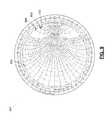
- FIG. 9depicts a Smith Chart illustrating an impedance matching capability of an antenna coupler mechanism.
- FIG. 10depicts two metallic objects in close proximity to illustrate a tuning capability of an antenna coupler mechanism.
- FIGS. 11A , 11 B, and 11 Cdepict three alternative configurations for an antenna coupler mechanism.
- FIG. 12depicts an antenna coupler mechanism placed within a recess of a metallic object.
- FIG. 13depicts an antenna coupler mechanism with first tuning leg, second tuning leg, and bottom plate elements stacked vertically from a surface of a metallic object.
- FIG. 14is a flowchart illustrating a method of coupling energy from an RF device into a metallic object.
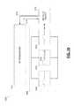
- FIG. 15depicts a system for determining a location of a metallic object.
- Radio frequency (RF) devicesare useful for tracking the location of objects.
- RFID tagsmay be affixed to an object and configured to transmit its unique identification number or other identifying information in response to an interrogation signal.
- tracking metallic objects with RF devices in this mannermay be difficult. For example, placing a small (e.g., less than one-tenth the RF device's operating wavelength) RFID tag containing an internal antenna near a metallic object often results in low radiation resistance, a poor impedance match, and poor efficiency at higher frequencies. This can result in a short read range for the RFID tag, which severely limits its location-tracking capabilities.
- RF devicesgenerally require the use of an antenna that is commensurate in size with the wavelength of the operating frequency of the RF device.
- the object to be trackedacts as the actual radiating element. Because antennas are conductive in nature, metallic objects of lengths approximately equal to one-half the operating wavelength of the RF device can serve as suitable antennas, in theory.
- An antenna coupler mechanismcan provide an interface between an RF device and a metallic object to be used as a radiating antenna.
- the antenna coupler mechanismallows for increased energy coupling between the RF device and the metallic object by providing an impedance match between the RF device and the metallic object and by providing a coupling mechanism.
- the antenna coupler mechanismcan be fabricated from standard printed circuit board material (e.g., FR4) and/or using discrete electrical components.
- Two exemplary RF devices that may be used with the antenna coupler mechanisminclude the NXP RFID UCODE G2iL and Silicon Labs Si4010 integrated circuits.
- FIGS. 1A and 1Bdepict a metallic object to be tracked by an RF device.
- the RF device 102is affixed directly to a surface of the metallic object 104 .
- the RF device 102could be, for example, an RFID tag.
- the location of the metallic object 104may not be tracked properly, due to the aforementioned problems that may be encountered when an RF device is placed near metal.
- FIG. 1Bdepicts the use of an antenna coupler mechanism 106 as an interface between an RF device 108 and a metallic object 110 .
- a length of the metallic objectis on the order of one-half of the operating wavelength of the RF device.
- the antenna coupler mechanism 106provides an interface that is conducive to energy coupling between the RF device 108 and the metallic object 110 and allows for impedance matching between the RF device 108 and the metallic object 110 . Due to the increased energy coupling between the two elements 108 , 110 , the metallic object 110 can function as an antenna, and the RF device's signals can be read at greater distances.
- An antennahas the characteristic of reciprocity, and as such, the antenna coupler mechanism 106 follows this theorem in that the antenna coupler mechanism 106 plus metallic object 110 form an antenna that operates identically in either direction.
- FIG. 2depicts an antenna coupler mechanism used to enable an RF device to communicate with an RF transceiver located a distance away from the RF device.
- An RF device 202 with a poorly-coupled metallic object antennamay be used only with transceivers located at close distances.
- using the antenna coupler mechanism 204 with a metallic object 206 as an antennacan enable the RF transceiver 208 to receive a signal from the RF device 202 at a longer distance.
- the RF device's signalmay be read reliably in both the near field and the far field.
- the antenna coupler mechanism 204may enable the use of remote receivers and more sophisticated applications (e.g., location tracking and remote environment sensing, etc.).
- FIG. 3depicts an antenna coupler mechanism mounted on a surface of a metallic object.
- the metallic object 302may have a length near one-half of an operating wavelength of an RF device.
- the center frequency of the UHF radio frequency identification bandhas a wavelength of approximately 328 millimeters, and metallic objects with lengths ranging from 100 millimeters to 230 millimeters may be effective antennas when used with the antenna coupler mechanism 304 .
- a shape of the metallic object 302can be geometrically non-uniform, allowing objects such as surgical instruments, tools, and food utensils to be used as antennas, especially when their length is approximately one-half the operating wavelength.
- Placement of the antenna coupler mechanism 304is ideally in the center of the metallic object, but the antenna coupler mechanism 304 can operate well over a wide variation from this location.
- FIG. 3depicts the antenna coupler mechanism 304 as protruding from the surface of the metallic object, alternative embodiments include where the antenna coupler mechanism 304 is placed within a recess of the metallic object 302 , thus allowing the metallic object 302 to retain its original appearance.
- FIG. 4depicts top and bottom views of an antenna coupler mechanism fabricated on printed circuit board.
- the antenna coupler mechanism 400is fabricated on standard printed circuit board material such as two-sided FR4.
- a first conductor 404covers a substantial portion of the bottom side of the antenna coupler mechanism.
- a first tuning leg 408comprises a second conductor connected in series with an RF device 410 (e.g., an RFID tag or an RF integrated circuit).
- the first tuning leg 408is connected in a parallel electrical configuration with the bottom plate 404 by a first set of electrical connections 412 .
- the top side 406also includes a second tuning leg 414 , which comprises a third conductor connected in series with a capacitor 416 .
- the second tuning leg 414is connected in a parallel electrical configuration with the bottom plate 404 by a second set of electrical connections 418 .
- the antenna coupler mechanismis placed on the metallic object such that the top side 406 of the antenna coupler mechanism is faced up, and the bottom side 402 of the antenna coupler mechanism is faced down towards the metallic object.
- the bottom plate 404placed in close proximity with the metallic object, is used to couple energy from the RF device to the metallic object.
- the first, second, and third conductors 404 , 408 , 414may be conductive traces printed on the top and bottom sides of the printed circuit board, and the first and second sets of electrical connections 412 , 418 may be conductive vias used to connect the traces on the top and bottom sides. Because the bottom plate 404 covers most of the bottom side 402 of the antenna coupler mechanism, the first 412 and second 418 sets of electrical connections are electrically connected, resulting in the first 408 and second 414 tuning legs to be connected to each other via a parallel electrical configuration.
- FIG. 5illustrates a first set of example dimensions for an antenna coupler mechanism.
- the antenna coupler mechanismhas a length, width, and thickness of 32.0 millimeters, 2.25 millimeters, and 0.64 millimeters, respectively.
- a first conductor 502comprises a trace on a bottom side of the antenna coupler mechanism and has a width of 2.25 millimeters, covering most of the bottom side.
- Second 504 and third 506 conductorscomprise traces on a top side of the antenna coupler mechanism and have widths of 0.5 millimeters and 1.0 millimeters, respectively.
- an NXP UCODE G2iL RF device 508 operating in the 902-928 MHz bandis connected in series with the second conductor 504 .
- a capacitor 510 having a capacitance value of 2.1 pFis connected in series with the third conductor 506 .
- FIG. 6illustrates a second set of example dimensions for another antenna coupler mechanism.
- a first conductorforms a bottom plate 602 that is connected in parallel with a first tuning leg 604 using a first set of electrical connections 606 .
- the bottom plate 602is also connected in parallel with a second tuning leg 608 using a second set of electrical connections 610 .
- the first set of electrical connections 606 used with the first tuning leg 604are smaller than the second set of electrical connections 610 used with the second tuning leg 608 .
- the first 606 and second 610 sets of electrical connectionscomprise conductive vias with diameters of 0.30 millimeters and 0.75 millimeters, respectively.
- the first tuning leg trace 504 and the first set of electrical connections vias 606are smaller than the second tuning leg trace 506 and the second set of electrical connections vias 610 .
- the smaller traces and viashave a greater intrinsic inductance than the larger traces and vias, causing the inductance from the capacitor to the bottom plate to be of a lower value than the inductance from the RF device to the bottom plate.
- the bottom plate traceis the widest of all conductors, it has the lowest overall inductance of the traces and vias.
- first and second sets of electrical connectionsare depicted as conductive vias in FIGS. 5 and 6 , alternative embodiments are included within the scope of this disclosure.
- the first and second sets of electrical connectionsmay each include a set of parallel metallic plates, such that electrical connections between top and bottom sides of the antenna coupler mechanism are made through capacitive coupling.
- Modification of any of the dimensions or other parameters of components depicted in FIGS. 5 and 6can result in changes in energy coupling between the bottom plate and the metallic object.
- Modifying a capacitance value of the capacitor or dimensions of the traces, vias, or the antenna coupler mechanism itselfchanges the energy coupling by transforming an impedance formed by a combination of an inductance value of the bottom plate in parallel with an impedance value of the metallic object.
- FIG. 7depicts a side profile view of an antenna coupler mechanism mounted on a metallic object.
- the antenna coupler mechanism 702is mounted on a surface of the metallic object 704 , and an RF device 706 protrudes from a top surface of the antenna coupler mechanism 702 .
- the antenna coupler mechanism 702is mounted on the metallic object 704 using a dielectric adhesive material 708 , which creates a controlled amount of spacing between a bottom plate 710 of the antenna coupler mechanism 702 and the metallic object 704 . In one example, the amount of spacing is 0.12 millimeter.
- Manipulation of the area of the bottom plate 710 , the amount of spacing, or the material occupying the amount of spacingcan change the energy coupling between the bottom plate 710 and the metallic object 704 .
- the metallic bottom plate 710 and the metallic object 704placed in close proximity with the dielectric material 708 separating them, form a capacitor.
- this exampleutilizes the dielectric adhesive material 708 , suspended structures with only air separating the bottom plate 708 and the metallic object 704 may also be fabricated.
- FIG. 8depicts a circuit diagram illustrating circuit elements of an antenna coupler mechanism.
- a first tuning leg 802includes a first inductive circuit element in series with an RF device 804
- a second tuning leg 806includes a second inductive circuit element in series with a capacitive circuit element 808 .
- an inductance value of the first inductive circuit elementis higher than an inductance value of the second inductive circuit element.
- the first inductive circuit elementcomprises two inductors connected in series
- the second inductive circuit elementalso comprises two inductors connected in series.
- a bottom plate 810comprising a third inductive circuit element is connected in parallel with the first tuning leg 802 and in parallel with the second tuning leg 806 . Through these parallel connections with the bottom plate 810 , the first and second tuning legs are also connected in parallel.
- the bottom plate 810is placed in close proximity with a metallic object 812 , and the bottom plate is configured to couple energy to the metallic object 812 .
- the antenna coupler mechanismis used to provide a coupling mechanism 814 between the RF device 804 and the metallic object 812 and to enable impedance matching between the RF device 804 and the metallic object 812 .
- the coupling mechanism 814includes a combination of inductive and capacitive coupling that occurs between the bottom plate 810 inductance in parallel with an impedance value of the metallic object 812 .
- the coupling mechanism 814causes the impedance value of the metallic object 812 to be increased by a coupling factor K.
- the coupling factor Kis primarily controlled by an area of the bottom plate 810 , an amount of spacing between bottom plate 810 and metallic object 812 , and a material occupying the amount of spacing. By changing one or more of these values, the coupling factor K is modified, and energy coupling between the bottom plate 810 and the metallic object 812 changes. For example, decreasing the amount of spacing increases the coupling factor K and results in increased energy coupling between the two elements.
- a complex conjugate impedance match between the RF device 804 and the metallic object 812can be achieved by modifying inductance and capacitance values of the first 802 and second 806 tuning legs. Modifying these values enables matching of the impedance of the metallic object 812 to the RF device 804 by transforming an impedance value formed by the combination of the inductance value of the bottom plate 810 in parallel with the impedance value of the metallic object 812 (hereinafter “coupling mechanism impedance”).
- the coupling mechanism impedanceis generally transformed to increase its inductive reactance.
- the inductance value of the bottom plate 810is relatively low, and thus, values of the circuit elements must be modified to increase the inductive reactance of the bottom plate 810 in order to properly transform the coupling mechanism impedance as needed.
- the coupling mechanism impedancecan be transformed via one or more of the following.
- the amount of spacing between the bottom plate 810 and the metallic object 812can be decreased to increase energy coupling between the two elements.
- decreasing the amount of spacingcan increase the coupling factor K.
- Increasing the coupling factor K in this mannercan increase the real impedance and reduce the inductive reactance of the coupling mechanism impedance, assuming that the length of the metallic object is near one-half the RF device's operating wavelength.
- the capacitance value of the capacitive circuit element 808 and the inductance value of the second tuning leg 806can be increased to affect both real and reactive impedance of the coupling mechanism impedance.
- an inductance value of the first tuning leg 802can be increased to further increase inductive reactance of the coupling mechanism impedance. Performing one or more of these actions allows the complex conjugate impedance of the metallic object to be modified to approximate that of the RF device.
- FIG. 8can be constructed with discrete inductor and capacitor circuit elements.
- FIG. 8can be viewed as an electrical model formed when circuit elements of FIGS. 4-7 are used.
- the inductive circuit elements of FIG. 8may be viewed as intrinsic inductances of the traces and vias of FIGS. 5 and 6 .
- FIG. 9depicts a Smith Chart illustrating an impedance matching capability of an antenna coupler mechanism.
- the RF deviceis a NXP UCODE G2iL IC RFID integrated circuit.
- This devicehas a complex conjugate impedance of 21+j199, shown on the Smith Chart of FIG. 9 at 902 .
- the impedance formed by the combination of the inductance value of the bottom plate in parallel with the impedance value of the metallic objecthereinafter “coupling mechanism impedance” is transformed to approximate the complex conjugate impedance value of the RF device by modifying circuit elements as described above.
- An intrinsic impedance value of the bottom plateis determined empirically to be 0.45+j35, which is found at location 904 . This low impedance value initially dominates the coupling mechanism impedance.
- the coupling mechanism impedanceis transformed from location 904 to location 906 (10+j156).
- the coupling mechanism impedanceis transformed from location 906 to location 908 (10+j200).
- the coupling mechanism impedance of 10+j200approximates that of the RF device at 21+j199, allowing for efficient energy coupling between the two elements.
- FIG. 10depicts two metallic objects in close proximity to illustrate a tuning capability of an antenna coupler mechanism.
- multiple metallic objectsmay be placed in close proximity with each other (e.g., surgical instruments may be placed in a pile on a table in an operating room).
- an RF device 1002is adhesively bonded to one metallic object 1004 , and another metallic object 1006 is located a short distance away.
- the coupler mechanism impedance transformationis such that major impedance changes to the metallic object 1004 have minor changes to impedance seen by the RF device 1002 .
- a bottom trace of the antenna coupler mechanismhas a small impedance, and this small impedance is in parallel with a larger impedance of the metallic object 1004 . Therefore, changes in the metallic object's impedance caused by another metallic object 1006 being nearby have little influence on the overall impedance seen by the RF device 1002 .
- FIGS. 11A , 11 B, and 11 Cdepict three alternative configurations for an antenna coupler mechanism.
- the antenna coupler mechanismmay be placed on the surface of the metallic object, with capacitor and RF device elements protruding from the top surface of the antenna coupler mechanism.
- the capacitor and RF device elements 1102may be countersunk into the surface of the antenna coupler mechanism 1104 , enabling the antenna coupler mechanism 1104 to have a flat top surface.
- FIG. 11BAnother alternative embodiment is depicted in FIG. 11B , wherein the capacitor and RF device elements 1106 are located within a material 1108 separating the antenna coupler mechanism and a metallic object. Like the embodiment depicted in FIG. 11A , this design also allows the antenna coupler mechanism to have a flat top surface.
- FIG. 11Cdepicts a third alternative embodiment of the antenna coupler mechanism, wherein the entire antenna coupler mechanism device 1110 is placed within a recess of metallic object 1112 .
- a bottom plate 1114is made flush with a surface of the metallic object 1112 , a portion of surface current flowing over the metallic object 1112 flows through the bottom plate 1114 and enables energy coupling to occur between RF device 1116 and the metallic object 1112 .
- FIG. 12depicts an antenna coupler mechanism placed within a recess of a metallic object.
- the antenna coupler mechanism 1202is placed within the recess 1204 of the metallic object 1206 , with a bottom plate 1208 of the antenna coupler mechanism facing out of the recess, towards the nearby surface of the metallic object 1206 .
- an external non-metallic stripmay be used to close the recess, as in FIG. 11C , or the metallic object may be fabricated to include the antenna coupler mechanism within a closed recess, as in FIG. 12 . Placing the antenna coupler mechanism within the metallic object in such a manner enables the metallic object to retain its original appearance and prevents inadvertent removal of the antenna coupler mechanism from the metallic object.
- FIG. 13depicts an antenna coupler mechanism with first tuning leg, second tuning leg, and bottom plate elements stacked vertically from a surface of a metallic object.
- the first and second tuning legscomprise a top plate, with the first tuning leg and the second tuning leg being coplanar.
- FIG. 13depicts an alternative embodiment, where the first tuning leg 1302 , the second tuning leg 1304 , and the bottom plate 1306 are stacked vertically from the surface of the metallic object 1308 , which can enable the antenna coupler mechanism to have a decreased width.
- FIG. 14is a flowchart illustrating a method of coupling energy between an RF device and a metallic object.
- a bottom plateis placed near a metallic object.
- the bottom plateincludes a first inductive circuit element and is configured to couple energy into the metallic object.
- a first tuning legis connected in parallel with the bottom plate.
- the first tuningcomprises a second inductive circuit element.
- a second tuning legis connected in parallel with the bottom plate.
- the second tuning legincludes a third inductive circuit element and a capacitive circuit element connected in series.
- the first tuning legincorporates a radio frequency device.
- the metallic objectis configured to receive energy that is coupled from the radio frequency device via the bottom plate.
- FIG. 15depicts a system for determining a location of a metallic object.
- the systemincludes an antenna coupler mechanism 1502 , which includes a first tuning leg 1504 , a second tuning 1506 , and a bottom plate 1508 .
- the first tuning leg 1504includes a radio frequency device 1510 .
- the systemalso includes a radio frequency transceiver 1512 configured to send an interrogation signal 1514 to the radio frequency device 1510 and to receive a response signal 1516 originating from the radio frequency device 1510 .
- the systemfurther includes a metallic object 1518 connected to the antenna coupler mechanism 1502 .
- the metallic object 1518is configured to receive the response signal 1516 via the bottom plate 1508 and to transmit the response signal 1516 to the radio frequency transceiver 1512 .
- RF deviceis meant to refer to any element involving radio frequency electronics, generally.
- RF deviceencompasses RF integrated circuits, RFID integrated circuits, RFID tags, and other RF transceivers and transponders.
- the RF devicemay or may not include an internal antenna element.
Landscapes
- Engineering & Computer Science (AREA)
- Physics & Mathematics (AREA)
- General Physics & Mathematics (AREA)
- Theoretical Computer Science (AREA)
- Computer Hardware Design (AREA)
- Microelectronics & Electronic Packaging (AREA)
- Electromagnetism (AREA)
- Computer Networks & Wireless Communication (AREA)
- Health & Medical Sciences (AREA)
- Toxicology (AREA)
- General Health & Medical Sciences (AREA)
- Artificial Intelligence (AREA)
- Computer Vision & Pattern Recognition (AREA)
- Details Of Aerials (AREA)
Abstract
Description
Claims (19)
Priority Applications (4)
| Application Number | Priority Date | Filing Date | Title |
|---|---|---|---|
| US13/358,168US8477076B1 (en) | 2012-01-25 | 2012-01-25 | Antenna coupler mechanism |
| US13/925,062US9515376B2 (en) | 2012-01-25 | 2013-06-24 | Antenna coupler mechanism |
| US15/349,590US10084227B2 (en) | 2012-01-25 | 2016-11-11 | Antenna coupler mechanism |
| US16/108,915US20180366810A1 (en) | 2012-01-25 | 2018-08-22 | Antenna Coupler Mechanism |
Applications Claiming Priority (1)
| Application Number | Priority Date | Filing Date | Title |
|---|---|---|---|
| US13/358,168US8477076B1 (en) | 2012-01-25 | 2012-01-25 | Antenna coupler mechanism |
Related Child Applications (1)
| Application Number | Title | Priority Date | Filing Date |
|---|---|---|---|
| US13/925,062ContinuationUS9515376B2 (en) | 2012-01-25 | 2013-06-24 | Antenna coupler mechanism |
Publications (2)
| Publication Number | Publication Date |
|---|---|
| US8477076B1true US8477076B1 (en) | 2013-07-02 |
| US20130187758A1 US20130187758A1 (en) | 2013-07-25 |
Family
ID=48671224
Family Applications (2)
| Application Number | Title | Priority Date | Filing Date |
|---|---|---|---|
| US13/358,168Expired - Fee RelatedUS8477076B1 (en) | 2012-01-25 | 2012-01-25 | Antenna coupler mechanism |
| US16/108,915AbandonedUS20180366810A1 (en) | 2012-01-25 | 2018-08-22 | Antenna Coupler Mechanism |
Family Applications After (1)
| Application Number | Title | Priority Date | Filing Date |
|---|---|---|---|
| US16/108,915AbandonedUS20180366810A1 (en) | 2012-01-25 | 2018-08-22 | Antenna Coupler Mechanism |
Country Status (1)
| Country | Link |
|---|---|
| US (2) | US8477076B1 (en) |
Cited By (14)
| Publication number | Priority date | Publication date | Assignee | Title |
|---|---|---|---|---|
| US9050235B2 (en) | 2008-10-28 | 2015-06-09 | Rf Surgical Systems, Inc. | Method and apparatus to detect transponder tagged objects, for example during medical procedures |
| US9226686B2 (en) | 2009-11-23 | 2016-01-05 | Rf Surgical Systems, Inc. | Method and apparatus to account for transponder tagged objects used during medical procedures |
| US9514341B2 (en) | 2014-03-31 | 2016-12-06 | Covidien Lp | Method, apparatus and article for detection of transponder tagged objects, for example during surgery |
| US9717565B2 (en) | 2015-01-21 | 2017-08-01 | Covidien Lp | Wirelessly detectable objects for use in medical procedures and methods of making same |
| US9763742B2 (en) | 2008-10-28 | 2017-09-19 | Covidien Lp | Wirelessly detectable objects for use in medical procedures and methods of making same |
| US9792408B2 (en) | 2009-07-02 | 2017-10-17 | Covidien Lp | Method and apparatus to detect transponder tagged objects and to communicate with medical telemetry devices, for example during medical procedures |
| US9872732B2 (en) | 2013-10-24 | 2018-01-23 | Covidien Lp | Surgical sponge distribution systems and methods |
| US10285775B2 (en) | 2015-02-26 | 2019-05-14 | Covidien Lp | Apparatuses to physically couple transponder to objects, such as surgical objects, and methods of using same |
| US10339269B2 (en) | 2014-03-31 | 2019-07-02 | Covidien Lp | Hand-held spherical antenna system to detect transponder tagged objects, for example during surgery |
| CN110168568A (en)* | 2017-01-11 | 2019-08-23 | 艾利丹尼森零售信息服务公司 | Small Differential Electric Field Activated UHF RFID Devices |
| EP3579149A1 (en)* | 2018-06-07 | 2019-12-11 | Gemü Gebr. Müller Apparatebau Gmbh & Co. Kommanditgesellschaf | Electronic characteristics for a metallic component of a system |
| US10660726B2 (en) | 2015-01-21 | 2020-05-26 | Covidien Lp | Sterilizable wirelessly detectable objects for use in medical procedures and methods of making same |
| US10874560B2 (en) | 2015-01-21 | 2020-12-29 | Covidien Lp | Detectable sponges for use in medical procedures and methods of making, packaging, and accounting for same |
| US11957632B2 (en) | 2020-10-02 | 2024-04-16 | Hill-Rom Services, Inc. | Wirelessly charged patient support apparatus system |
Families Citing this family (14)
| Publication number | Priority date | Publication date | Assignee | Title |
|---|---|---|---|---|
| US10417380B1 (en) | 2013-12-31 | 2019-09-17 | Mckesson Corporation | Systems and methods for determining and communicating a prescription benefit coverage denial to a prescriber |
| US10489552B2 (en) | 2014-02-14 | 2019-11-26 | Mckesson Corporation | Systems and methods for determining and communicating patient incentive information to a prescriber |
| US10157262B1 (en) | 2015-03-10 | 2018-12-18 | Mckesson Corporation | Systems and methods for determining patient financial responsibility for multiple prescription products |
| US11514137B1 (en) | 2016-03-30 | 2022-11-29 | Mckesson Corporation | Alternative therapy identification system |
| US10999224B1 (en) | 2017-02-01 | 2021-05-04 | Mckesson Corporation | Method and apparatus for parsing an electronic message and constructing multiple differently prioritized messages therefrom |
| US10862832B1 (en) | 2018-07-24 | 2020-12-08 | Mckesson Corporation | Computing system and method for automatically reversing an action indicated by an electronic message |
| US11636548B1 (en) | 2019-06-26 | 2023-04-25 | Mckesson Corporation | Method, apparatus, and computer program product for providing estimated prescription costs |
| US11562437B1 (en) | 2019-06-26 | 2023-01-24 | Mckesson Corporation | Method, apparatus, and computer program product for providing estimated prescription costs |
| US12229834B1 (en) | 2020-02-17 | 2025-02-18 | Mckesson Corporation | Method, apparatus, and computer program product for partitioning prescription transaction costs in an electronic prescription transaction |
| US11610240B1 (en) | 2020-02-17 | 2023-03-21 | Mckesson Corporation | Method, apparatus, and computer program product for partitioning prescription transaction costs in an electronic prescription transaction |
| US12229833B1 (en) | 2020-02-17 | 2025-02-18 | Mckesson Corporation | Method, apparatus, and computer program product for reformatting an electronic prescription transaction |
| US11587657B2 (en) | 2020-09-04 | 2023-02-21 | Mckesson Corporation | Method, apparatus, and computer program product for performing an alternative evaluation procedure in response to an electronic message |
| US12367954B1 (en) | 2021-01-08 | 2025-07-22 | Mckesson Corporation | Method, apparatus, and computer program product for estimating a target quantitative measure based upon historical electronic messages |
| US12197972B1 (en) | 2022-03-28 | 2025-01-14 | Mckesson Corporation | Method, apparatus, and computer program product for generating alternative evaluation messages |
Citations (7)
| Publication number | Priority date | Publication date | Assignee | Title |
|---|---|---|---|---|
| US20070262867A1 (en)* | 2006-05-12 | 2007-11-15 | Westrick Michael D | Rfid coupler for metallic implements |
| US7508347B2 (en)* | 2006-11-10 | 2009-03-24 | Hitachi, Ltd. | Radio frequency integrated circuit tag and method of using the RFIC tag |
| US7880614B2 (en)* | 2007-09-26 | 2011-02-01 | Avery Dennison Corporation | RFID interposer with impedance matching |
| US7938334B2 (en)* | 2007-04-18 | 2011-05-10 | 3M Innovative Properties Copmpany | Radio frequency identification functionality coupled to electrically conductive signage |
| US8023890B2 (en)* | 2006-09-11 | 2011-09-20 | Sony Corporation | Communication system, communication apparatus, and electric-field-coupling antenna |
| US20110254745A1 (en)* | 2007-09-05 | 2011-10-20 | Kabushiki Kaisha Toshiba | Wireless communication device and antenna |
| US8063760B2 (en)* | 2003-03-03 | 2011-11-22 | Veroscan, Inc. | Interrogator and interrogation system employing the same |
Family Cites Families (13)
| Publication number | Priority date | Publication date | Assignee | Title |
|---|---|---|---|---|
| US4114601A (en)* | 1976-08-09 | 1978-09-19 | Micro Tec Instrumentation, Inc. | Medical and surgical implement detection system |
| WO2003048810A2 (en)* | 2001-12-03 | 2003-06-12 | Fabian Carl E | Portable surgical implement detector |
| US7492261B2 (en)* | 2004-11-22 | 2009-02-17 | Warsaw Orthopedic, Inc. | Control system for an RFID-based system for assembling and verifying outbound surgical equipment corresponding to a particular surgery |
| US7268684B2 (en)* | 2004-12-08 | 2007-09-11 | Sdgi Holdings, Inc. | Workstation RFID reader for surgical instruments and surgical instrument trays and methods of using same |
| US8229871B2 (en)* | 2004-12-29 | 2012-07-24 | Woolf Tod M | Systems and methods for computer aided inventing |
| US7307530B2 (en)* | 2005-02-10 | 2007-12-11 | Fabian Carl E | Surgical implement detector utilizing a radio-frequency identification marker |
| US7420468B2 (en)* | 2005-02-10 | 2008-09-02 | Fabian Carl E | Surgical implement detector |
| US7837694B2 (en)* | 2005-04-28 | 2010-11-23 | Warsaw Orthopedic, Inc. | Method and apparatus for surgical instrument identification |
| US8193938B2 (en)* | 2009-02-12 | 2012-06-05 | Haldor Advanced Technologies Ltd. | Apparatus for identifying and tracking multiple tools and disposables |
| FR2974496B1 (en)* | 2011-04-26 | 2014-10-17 | Marc Antoine Sergeant | MEDICAL DEVICE HAVING AN INNOVATIVE MARKING SYSTEM FOR RAPID, MULTIPLE AND REMOTE IDENTIFICATION |
| DE102011052501A1 (en)* | 2011-08-08 | 2013-02-14 | Aesculap Ag | RFID tag |
| US9387002B2 (en)* | 2014-03-31 | 2016-07-12 | Shanghai Yaochuan Information Technology Co., Ltd. | Surgical instrument |
| US10002269B2 (en)* | 2014-09-04 | 2018-06-19 | Haldor Advanced Technologies Ltd | Mobile handheld antenna for reading tags |
- 2012
- 2012-01-25USUS13/358,168patent/US8477076B1/ennot_activeExpired - Fee Related
- 2018
- 2018-08-22USUS16/108,915patent/US20180366810A1/ennot_activeAbandoned
Patent Citations (7)
| Publication number | Priority date | Publication date | Assignee | Title |
|---|---|---|---|---|
| US8063760B2 (en)* | 2003-03-03 | 2011-11-22 | Veroscan, Inc. | Interrogator and interrogation system employing the same |
| US20070262867A1 (en)* | 2006-05-12 | 2007-11-15 | Westrick Michael D | Rfid coupler for metallic implements |
| US8023890B2 (en)* | 2006-09-11 | 2011-09-20 | Sony Corporation | Communication system, communication apparatus, and electric-field-coupling antenna |
| US7508347B2 (en)* | 2006-11-10 | 2009-03-24 | Hitachi, Ltd. | Radio frequency integrated circuit tag and method of using the RFIC tag |
| US7938334B2 (en)* | 2007-04-18 | 2011-05-10 | 3M Innovative Properties Copmpany | Radio frequency identification functionality coupled to electrically conductive signage |
| US20110254745A1 (en)* | 2007-09-05 | 2011-10-20 | Kabushiki Kaisha Toshiba | Wireless communication device and antenna |
| US7880614B2 (en)* | 2007-09-26 | 2011-02-01 | Avery Dennison Corporation | RFID interposer with impedance matching |
Cited By (22)
| Publication number | Priority date | Publication date | Assignee | Title |
|---|---|---|---|---|
| US10369067B2 (en) | 2008-10-28 | 2019-08-06 | Covidien Lp | Method and apparatus to detect transponder tagged objects, for example during medical procedures |
| US9730850B2 (en) | 2008-10-28 | 2017-08-15 | Covidien Lp | Method and apparatus to detect transponder tagged objects, for example during medical procedures |
| US9763742B2 (en) | 2008-10-28 | 2017-09-19 | Covidien Lp | Wirelessly detectable objects for use in medical procedures and methods of making same |
| US9050235B2 (en) | 2008-10-28 | 2015-06-09 | Rf Surgical Systems, Inc. | Method and apparatus to detect transponder tagged objects, for example during medical procedures |
| US10595958B2 (en) | 2008-10-28 | 2020-03-24 | Covidien Lp | Wirelessly detectable objects for use in medical procedures and methods of making same |
| US9792408B2 (en) | 2009-07-02 | 2017-10-17 | Covidien Lp | Method and apparatus to detect transponder tagged objects and to communicate with medical telemetry devices, for example during medical procedures |
| US10722323B2 (en) | 2009-11-23 | 2020-07-28 | Covidien Lp | Method and apparatus to account for transponder tagged objects used during medical procedures |
| US9226686B2 (en) | 2009-11-23 | 2016-01-05 | Rf Surgical Systems, Inc. | Method and apparatus to account for transponder tagged objects used during medical procedures |
| US9872732B2 (en) | 2013-10-24 | 2018-01-23 | Covidien Lp | Surgical sponge distribution systems and methods |
| US10339269B2 (en) | 2014-03-31 | 2019-07-02 | Covidien Lp | Hand-held spherical antenna system to detect transponder tagged objects, for example during surgery |
| US9514341B2 (en) | 2014-03-31 | 2016-12-06 | Covidien Lp | Method, apparatus and article for detection of transponder tagged objects, for example during surgery |
| US11238973B2 (en) | 2014-03-31 | 2022-02-01 | Covidien Lp | Hand-held spherical antenna system to detect transponder tagged objects, for example during surgery |
| US10874560B2 (en) | 2015-01-21 | 2020-12-29 | Covidien Lp | Detectable sponges for use in medical procedures and methods of making, packaging, and accounting for same |
| US10660726B2 (en) | 2015-01-21 | 2020-05-26 | Covidien Lp | Sterilizable wirelessly detectable objects for use in medical procedures and methods of making same |
| US11065081B2 (en) | 2015-01-21 | 2021-07-20 | Covidien Lp | Sterilizable wirelessly detectable objects for use in medical procedures and methods of making same |
| US9717565B2 (en) | 2015-01-21 | 2017-08-01 | Covidien Lp | Wirelessly detectable objects for use in medical procedures and methods of making same |
| US12329592B2 (en) | 2015-01-21 | 2025-06-17 | Covidien Lp | Sterilizable wirelessly detectable objects for use in medical procedures and methods of making same |
| US10285775B2 (en) | 2015-02-26 | 2019-05-14 | Covidien Lp | Apparatuses to physically couple transponder to objects, such as surgical objects, and methods of using same |
| US10888394B2 (en) | 2015-02-26 | 2021-01-12 | Covidien Lp | Apparatuses to physically couple transponder to objects, such as surgical objects, and methods of using same |
| CN110168568A (en)* | 2017-01-11 | 2019-08-23 | 艾利丹尼森零售信息服务公司 | Small Differential Electric Field Activated UHF RFID Devices |
| EP3579149A1 (en)* | 2018-06-07 | 2019-12-11 | Gemü Gebr. Müller Apparatebau Gmbh & Co. Kommanditgesellschaf | Electronic characteristics for a metallic component of a system |
| US11957632B2 (en) | 2020-10-02 | 2024-04-16 | Hill-Rom Services, Inc. | Wirelessly charged patient support apparatus system |
Also Published As
| Publication number | Publication date |
|---|---|
| US20180366810A1 (en) | 2018-12-20 |
| US20130187758A1 (en) | 2013-07-25 |
Similar Documents
| Publication | Publication Date | Title |
|---|---|---|
| US8477076B1 (en) | Antenna coupler mechanism | |
| US8477077B1 (en) | Antenna coupler mechanism systems and methods | |
| US10084227B2 (en) | Antenna coupler mechanism | |
| US9010648B2 (en) | Antenna and RFID tag | |
| TWI525899B (en) | Rfid tag antenna | |
| JP6253588B2 (en) | Antenna structure and RFID transponder system provided with antenna structure | |
| US8654012B2 (en) | Tag antenna using microstrip line, method of manufacturing the same and radio frequency identification tag | |
| CN101593866A (en) | Dielectric Resonant UHF RFID Tag Antenna with T-Type Matching Network | |
| US8690068B2 (en) | Miniaturized UHF RFID tag for implantable medical device | |
| Tan et al. | Compact dual band tag antenna design for radio frequency identification (RFID) application | |
| US8339318B2 (en) | RFID UHF antenna and matching network embedded in disposable conducting covers | |
| Santiago et al. | Broadband UHF RFID passive tag antenna for near-body operation | |
| JP2010268023A (en) | IC tag | |
| CN211699013U (en) | Double-frequency RFID anti-metal signboard intelligent device | |
| CN103956580A (en) | UHF plane inverted-F and monopole combined antenna applied to RFID reader-writer | |
| FI130267B (en) | A uhf rfid tag | |
| CN206293606U (en) | A kind of PCB antenna and rfid interrogator | |
| KR101720688B1 (en) | Microstrip antenna | |
| CN104157958B (en) | Internet of things UHF RFID (ultra high frequency radio frequency identification) circularly polarized reader-writer antenna | |
| KR101516257B1 (en) | RFID tag device for thick steel plate | |
| Choo et al. | A novel multi-loop tag for near field communication in UHF band | |
| KR20120116028A (en) | Microstrip antenna for rfid tag | |
| Polycarpou et al. | Design procedure of UHF RFID reader antennas based on ETSI and FCC standards | |
| CN105098339B (en) | UHF frequency range RFID reader antenna and system | |
| CN102467675B (en) | A kind of radio-frequency (RF) tag and resonant circuit structure thereof |
Legal Events
| Date | Code | Title | Description |
|---|---|---|---|
| AS | Assignment | Owner name:CLEARCOUNT MEDICAL SOLUTIONS, INC., PENNSYLVANIA Free format text:ASSIGNMENT OF ASSIGNORS INTEREST;ASSIGNORS:NERO, REGIS J., JR.;FLECK, STEVEN J.;REEL/FRAME:027593/0826 Effective date:20120125 | |
| STCF | Information on status: patent grant | Free format text:PATENTED CASE | |
| AS | Assignment | Owner name:CLEARCOUNT MEDICAL SOLUTIONS, INC., PENNSYLVANIA Free format text:RELEASE OF SECURITY INTEREST;ASSIGNOR:MEDLINE INDUSTRIES, INC.;REEL/FRAME:033532/0093 Effective date:20140813 | |
| AS | Assignment | Owner name:STRYKER COMBO, L.L.C., MICHIGAN Free format text:ASSIGNMENT OF ASSIGNORS INTEREST;ASSIGNOR:CLEARCOUNT MEDICAL SOLUTIONS, INC.;REEL/FRAME:033736/0596 Effective date:20140813 | |
| FEPP | Fee payment procedure | Free format text:PAT HOLDER NO LONGER CLAIMS SMALL ENTITY STATUS, ENTITY STATUS SET TO UNDISCOUNTED (ORIGINAL EVENT CODE: STOL); ENTITY STATUS OF PATENT OWNER: LARGE ENTITY | |
| FPAY | Fee payment | Year of fee payment:4 | |
| AS | Assignment | Owner name:STRYKER CORPORATION, MICHIGAN Free format text:ASSIGNMENT OF ASSIGNORS INTEREST;ASSIGNOR:STRYKER COMBO L.L.C.;REEL/FRAME:049114/0819 Effective date:20190501 | |
| MAFP | Maintenance fee payment | Free format text:PAYMENT OF MAINTENANCE FEE, 8TH YEAR, LARGE ENTITY (ORIGINAL EVENT CODE: M1552); ENTITY STATUS OF PATENT OWNER: LARGE ENTITY Year of fee payment:8 | |
| FEPP | Fee payment procedure | Free format text:MAINTENANCE FEE REMINDER MAILED (ORIGINAL EVENT CODE: REM.); ENTITY STATUS OF PATENT OWNER: LARGE ENTITY | |
| LAPS | Lapse for failure to pay maintenance fees | Free format text:PATENT EXPIRED FOR FAILURE TO PAY MAINTENANCE FEES (ORIGINAL EVENT CODE: EXP.); ENTITY STATUS OF PATENT OWNER: LARGE ENTITY | |
| STCH | Information on status: patent discontinuation | Free format text:PATENT EXPIRED DUE TO NONPAYMENT OF MAINTENANCE FEES UNDER 37 CFR 1.362 | |
| FP | Lapsed due to failure to pay maintenance fee | Effective date:20250702 |