US8476846B1 - Stochastic signal density modulation for optical transducer control - Google Patents
Stochastic signal density modulation for optical transducer controlDownload PDFInfo
- Publication number
- US8476846B1 US8476846B1US13/403,242US201213403242AUS8476846B1US 8476846 B1US8476846 B1US 8476846B1US 201213403242 AUS201213403242 AUS 201213403242AUS 8476846 B1US8476846 B1US 8476846B1
- Authority
- US
- United States
- Prior art keywords
- stochastic
- signal
- signal density
- values
- value
- Prior art date
- Legal status (The legal status is an assumption and is not a legal conclusion. Google has not performed a legal analysis and makes no representation as to the accuracy of the status listed.)
- Expired - Fee Related
Links
Images


Classifications
- H—ELECTRICITY
- H05—ELECTRIC TECHNIQUES NOT OTHERWISE PROVIDED FOR
- H05B—ELECTRIC HEATING; ELECTRIC LIGHT SOURCES NOT OTHERWISE PROVIDED FOR; CIRCUIT ARRANGEMENTS FOR ELECTRIC LIGHT SOURCES, IN GENERAL
- H05B45/00—Circuit arrangements for operating light-emitting diodes [LED]
- H05B45/30—Driver circuits
- H—ELECTRICITY
- H05—ELECTRIC TECHNIQUES NOT OTHERWISE PROVIDED FOR
- H05B—ELECTRIC HEATING; ELECTRIC LIGHT SOURCES NOT OTHERWISE PROVIDED FOR; CIRCUIT ARRANGEMENTS FOR ELECTRIC LIGHT SOURCES, IN GENERAL
- H05B45/00—Circuit arrangements for operating light-emitting diodes [LED]
- H05B45/40—Details of LED load circuits
- H05B45/44—Details of LED load circuits with an active control inside an LED matrix
- H05B45/46—Details of LED load circuits with an active control inside an LED matrix having LEDs disposed in parallel lines
- H—ELECTRICITY
- H05—ELECTRIC TECHNIQUES NOT OTHERWISE PROVIDED FOR
- H05B—ELECTRIC HEATING; ELECTRIC LIGHT SOURCES NOT OTHERWISE PROVIDED FOR; CIRCUIT ARRANGEMENTS FOR ELECTRIC LIGHT SOURCES, IN GENERAL
- H05B45/00—Circuit arrangements for operating light-emitting diodes [LED]
- H05B45/10—Controlling the intensity of the light
- H05B45/18—Controlling the intensity of the light using temperature feedback
- H—ELECTRICITY
- H05—ELECTRIC TECHNIQUES NOT OTHERWISE PROVIDED FOR
- H05B—ELECTRIC HEATING; ELECTRIC LIGHT SOURCES NOT OTHERWISE PROVIDED FOR; CIRCUIT ARRANGEMENTS FOR ELECTRIC LIGHT SOURCES, IN GENERAL
- H05B45/00—Circuit arrangements for operating light-emitting diodes [LED]
- H05B45/20—Controlling the colour of the light
Definitions
- Embodiments of the present inventionrelate to the field of optical transducer control and, in particular, to the use of stochastic modulation waveforms for intensity control of light-emitting diodes.
- LEDLight-emitting diode
- RGBred, green and blue
- FIG. 1illustrates one embodiment of a stochastic signal density modulator for dimming control of an optical transducer
- FIG. 2illustrates two waveforms corresponding to two different stochastic signal densities in one embodiment
- FIG. 3illustrates the spectral signature of one embodiment of stochastic signal density modulation
- FIG. 4illustrates the spectral signature of another embodiment of stochastic signal density modulation
- FIG. 5illustrates an electronic system for stochastic signal density modulation of optical transducers in one embodiment.
- Described hereinare methods and apparatus for controlling optical transducers using stochastic signal density modulation.
- the following descriptionsets forth numerous specific details such as examples of specific systems, components, methods and so forth, in order to provide a good understanding of several embodiments of the present invention. It will be apparent to one skilled in the art, however, that at least some embodiments of the present invention may be practiced without these specific details. In other instances, well-known components or methods are not described in detail or are presented in simple block diagram format in order to avoid unnecessarily obscuring the present invention. Thus, the specific details set forth are merely exemplary. Particular implementations may vary from these exemplary details and still be contemplated to be within the spirit and scope of the present invention.
- a method for controlling an optical transducerincludes providing a controllable current to a light-emitting diode and stochastically controlling the current to select a light intensity output from the light-emitting diode.
- an apparatus for controlling an optical transducerincludes a controllable current supply coupled to a light-emitting diode and a controller coupled to the controllable current supply, where the controller is configured to provide a stochastic control signal to the controllable current supply and where the stochastic control signal has a selected stochastic signal density to control the output intensity of the light-emitting diode.
- FIG. 1is a block diagram 100 illustrating stochastic signal density modulation of an LED in one embodiment.
- FIG. 1includes a stochastic signal density modulator (SSDM) 101 that is coupled to a controllable current supply 102 and drives an LED 103 .
- the SSDM 101includes an n-bit stochastic state machine 105 , coupled to a first input of an n-bit comparator 104 .
- SSDM 101also includes an n-bit signal density register 106 , coupled to a second input of n-bit comparator 104 .
- Signal density register 106may be any type of programmable register or latch as is known in the art.
- stochastic state machine 105is clocked by clock signal f CLOCK on line 107 and generates an n-bit pseudorandom binary number between 0 and 2 n ⁇ 1 on each clock cycle.
- the signal density register 106is loaded with an n-bit binary value on input line 108 between 0 and 2 n ⁇ 1 corresponding to a signal density between 0 and 100% as described below.
- the signal density value in signal density register 106is compared in comparator 104 with the output of stochastic state machine 105 . When the output value of stochastic state machine 105 is greater than the value in the signal density register 106 , the output of comparator 104 is in a first state (e.g., high).
- the output of the comparator 104is in a second state (e.g., low).
- the output values of stochastic state machine 105forms a stationary pseudorandom process with a uniform probability distribution over the binary number space from 0 to 2 n ⁇ 1. Therefore, if the value in the signal density register 106 is m (where 0 ⁇ m ⁇ 2 n -1), the output of stochastic state machine 105 will be below m for m/(2 n ⁇ 1) percent of the time and above m for 1 ⁇ m/(2 n ⁇ 1) percent of the time.
- the output 109 of comparator 104will be in the first state for m/(2 n ⁇ 1) percent of the time and in the second state for 1 ⁇ m/(2 n ⁇ 1) percent of the time, but with a pseudorandom distribution.
- the output 109 of comparator 104is a pseudorandom modulation (PRM) which drives the controllable current supply 102 .
- PRMpseudorandom modulation
- the PRMWhen the PRM is in the first state, the controllable current supply 102 is on and the current through LED 103 is I.
- the PRMWhen the PRM is in the second state, the controllable current supply 102 is off and the current through LED 103 is zero (it will be appreciated that in other embodiments, current supply 102 may switch between two non-zero current states).
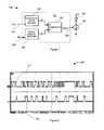
- FIG. 2is an oscillograph 200 illustrating the current through LED 103 in one embodiment for two different values of signal density.
- the upper trace 211illustrates the LED current for a signal density of 50% and the lower trace 212 illustrates the LED current for a signal density of 14%.
- both spectra 300 and 400contain no sharp spectral lines, that the peak response of these spectrum 300 is approximately 30 dB below the peak of the corresponding PWM spectrum ( FIG. 3 ), and that the frequency centroid of spectrum 300 is an order of magnitude greater than the corresponding PWM spectrum.
- the absence of spectral peaks and the increase in frequencyreduces EMI content relative to uniform frequency modulation/
- Stochastic state machine 105may be embodied in a variety of ways.
- stochastic state machine 105may be a stochastic counter such as a pseudorandom number.
- a pseudorandom number generatormay be implemented, for example, as an n-bit linear feedback shift register as is known in the art.
- n separate n-bit linear feedback shift registersmay be used in parallel to generate pseudorandom numbers.
- stochastic state machine 105may be a processing device having memory to hold data and instructions for the processing device to generate pseudorandom numbers.
- stochastic state machine 105may be a true random number generator based on a random process such as thermionic emission of electrons or radioactive decay of alpha or beta particles.
- the anode of LED 103is coupled to a positive voltage supply V DD and the cathode of LED 103 is coupled to current supply 102 , which is in turn coupled to ground, such that current supply 102 sinks current from LED 103 .
- the relative positions of current supply 102 and LEDmay be reversed such that the cathode of LED 103 is coupled to ground and the current supply 102 is coupled to the positive voltage supply, so that current supply 102 sources current to LED 103 .
- the positive voltage supplymay be replaced with a ground connection and the ground connection may be replaced with a negative voltage supply.
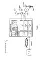
- FIG. 5illustrates a block diagram of one embodiment of an electronic system 500 in which embodiments of the present invention may be implemented.
- Electronic system 500includes processing device 210 and may include one or more arrays of LEDs.
- electronic system 500includes an array of RGB LEDs including red LED 103 R, green LED 103 G and blue LED 103 B and their corresponding controllable current supplies 102 R, 102 G and 102 B.
- Electronic system 500may also include a host processor 250 and an embedded controller 260 .
- the processing device 210may include analog and/or digital general purpose input/output (“GPIO”) ports 207 .
- GPIO ports 207may be programmable.
- GPIO ports 207may be coupled to a Programmable Interconnect and Logic (“PIL”), which acts as an interconnect between GPIO ports 207 and a digital block array of the processing device 210 (not illustrated).
- PILProgrammable Interconnect and Logic
- the digital block arraymay be configured to implement a variety of digital logic circuits (e.g., DAC, UARTs, timers, etc.) using, in one embodiment, configurable user modules (“UMs”).
- UMsconfigurable user modules
- the digital block arraymay be coupled to a system bus (not illustrated).
- Processing device 210may also include memory, such as random access memory (RAM) 205 and program memory 204 .
- RAM 205may be static RAM (SRAM), dynamic RAM (DRAM) or any other type of random access memory.
- Program memory 204may be any type of non-volatile storage, such as flash memory for example, which may be used to store firmware (e.g., control algorithms executable by processing core 202 to implement operations described herein).
- Processing device 210may also include a memory controller unit (MCU) 203 coupled to memory and the processing core 202 .
- MCUmemory controller unit
- the processing device 210may also include an analog block array (not illustrated).
- the analog block arrayis also coupled to the system bus.
- the analog block arrayalso may be configured to implement a variety of analog circuits (e.g., ADC, analog filters, etc.) using, in one embodiment, configurable UMs.
- the analog block arraymay also be coupled to the GPIO 207 .
- processing device 210may be configured to control color mixing.
- Processing device 210may include multiple stochastic signal density modulators (SSDM) 101 as described above, which are connected to current supplies 102 R, 102 G and 102 B for the control of LEDs 103 R, 103 G and 103 B, which may be red, green and blue LEDs, respectively.
- LEDs 103 R, 103 G and 103 Bmay be combinations of other primary, secondary and/or complementary colors.
- Processing device 210may include internal oscillator/clocks 206 and communication block 208 .
- the oscillator/clocks block 206provides clock signals to one or more of the components of processing device 210 .
- Communication block 208may be used to communicate with an external component, such as host processor 250 , via host interface (I/F) line 251 .
- processing device 210may also be coupled to embedded controller 260 to communicate with the external components, such as host 250 .
- Interfacing to the host 250can be achieved through various methods. In one exemplary embodiment, interfacing with the host 250 may be done using a standard PS/2 interface to connect to an embedded controller 260 , which in turn sends data to the host 250 via low pin count (LPC) interface.
- LPClow pin count
- interfacingmay be done using a universal serial bus (USB) interface directly coupled to the host 250 via host interface line 251 .
- the processing device 210may communicate to external components, such as the host 250 using industry standard interfaces, such as USB, PS/2, inter-integrated circuit (I2C) bus, or system packet interfaces (SPI).
- the host 250 and/or embedded controller 260may be coupled to the processing device 210 with a ribbon or flex cable from an assembly, which houses the sensing device and processing device.
- the processing device 210may operate to communicate data (e.g., commands or signals to control the absolute and/or relative intensities of LEDs 103 R, 103 G and 103 B)) using hardware, software, and/or firmware, and the data may be communicated directly to the processing device of the host 250 , such as a host processor, or alternatively, may be communicated to the host 250 via drivers of the host 250 , such as OS drivers, or other non-OS drivers. It should also be noted that the host 250 may directly communicate with the processing device 210 via host interface 251 .
- datae.g., commands or signals to control the absolute and/or relative intensities of LEDs 103 R, 103 G and 103 B
- the datamay be communicated directly to the processing device of the host 250 , such as a host processor, or alternatively, may be communicated to the host 250 via drivers of the host 250 , such as OS drivers, or other non-OS drivers.
- the host 250may directly communicate with the processing device 210 via host interface 251 .
- Processing device 210may reside on a common carrier substrate such as, for example, an integrated circuit (IC) die substrate, a multi-chip module substrate, or the like. Alternatively, the components of processing device 210 may be one or more separate integrated circuits and/or discrete components. In one exemplary embodiment, processing device 210 may be a Programmable System on a Chip (PSoCTM) processing device, manufactured by Cypress Semiconductor Corporation, San Jose, Calif. Alternatively, processing device 210 may be one or more other processing devices known by those of ordinary skill in the art, such as a microprocessor or central processing unit, a controller, special-purpose processor, digital signal processor (DSP), an application specific integrated circuit (ASIC), a field programmable gate array (FPGA), or the like. In an alternative embodiment, for example, the processing device may be a network processor having multiple processors including a core unit and multiple microengines. Additionally, the processing device may include any combination of general-purpose processing device(s) and special-purpose processing device(s).
- POPTMProgrammable
- SSDM 101may be integrated into the IC of the processing device 210 , or alternatively, in a separate IC. Alternatively, descriptions of SSDM 101 may be generated and compiled for incorporation into other integrated circuits. For example, behavioral level code describing SSDM 101 , or portions thereof, may be generated using a hardware descriptive language, such as VHDL or Verilog, and stored to a machine-accessible medium (e.g., CD-ROM, hard disk, floppy disk, etc.). Furthermore, the behavioral level code can be compiled into register transfer level (“RTL”) code, a, or even a circuit layout and stored to a machine-accessible medium. The behavioral level code, the RTL code, the netlist, and the circuit layout all represent various levels of abstraction to describe SSDM 101 .
- a hardware descriptive languagesuch as VHDL or Verilog
- electronic system 500may include all the components described above. Alternatively, electronic system 500 may include only some of the components described above.
- Embodiments of the present inventioninclude various operations. These operations may be performed by hardware components, software, firmware, or a combination thereof. Any of the signals provided over various buses described herein may be time multiplexed with other signals and provided over one or more common buses. Additionally, the interconnection between circuit components or blocks may be shown as buses or as single signal lines. Each of the buses may alternatively be one or more single signal lines and each of the single signal lines may alternatively be buses.
- Certain embodimentsmay be implemented as a computer program product that may include instructions stored on a machine-readable medium. These instructions may be used to program a general-purpose or special-purpose processor to perform the described operations.
- a machine-readable mediumincludes any mechanism for storing or transmitting information in a form (e.g., software, processing application) readable by a machine (e.g., a computer).
- the machine-readable mediummay include, but is not limited to, magnetic storage medium (e.g., floppy diskette); optical storage medium (e.g., CD-ROM); magneto-optical storage medium; read-only memory (ROM); random-access memory (RAM); erasable programmable memory (e.g., EPROM and EEPROM); flash memory; electrical, optical, acoustical, or other form of propagated signal (e.g., carrier waves, infrared signals, digital signals, etc.); or another type of medium suitable for storing electronic instructions.
- magnetic storage mediume.g., floppy diskette
- optical storage mediume.g., CD-ROM
- magneto-optical storage mediume.g., magneto-optical storage medium
- ROMread-only memory
- RAMrandom-access memory
- EPROM and EEPROMerasable programmable memory
- flash memoryelectrical, optical, acoustical, or other form of propagated signal (e.g., carrier waves, in
- some embodimentsmay be practiced in distributed computing environments where the machine-readable medium is stored on and/or executed by more than one computer system.
- the information transferred between computer systemsmay either be pulled or pushed across the communication medium connecting the computer systems.
Landscapes
- Circuit Arrangement For Electric Light Sources In General (AREA)
- Led Devices (AREA)
Abstract
Description
Claims (16)
Priority Applications (4)
| Application Number | Priority Date | Filing Date | Title |
|---|---|---|---|
| US13/403,242US8476846B1 (en) | 2006-11-13 | 2012-02-23 | Stochastic signal density modulation for optical transducer control |
| US13/934,032US9226355B1 (en) | 2006-11-13 | 2013-07-02 | Stochastic signal density modulation for optical transducer control |
| US14/944,388US9750097B1 (en) | 2006-11-13 | 2015-11-18 | Stochastic signal density modulation for optical transducer control |
| US15/661,795US10334672B2 (en) | 2006-11-13 | 2017-07-27 | Stochastic signal density modulation for optical transducer control |
Applications Claiming Priority (2)
| Application Number | Priority Date | Filing Date | Title |
|---|---|---|---|
| US11/598,981US8129924B2 (en) | 2006-11-13 | 2006-11-13 | Stochastic signal density modulation for optical transducer control |
| US13/403,242US8476846B1 (en) | 2006-11-13 | 2012-02-23 | Stochastic signal density modulation for optical transducer control |
Related Parent Applications (1)
| Application Number | Title | Priority Date | Filing Date |
|---|---|---|---|
| US11/598,981ContinuationUS8129924B2 (en) | 2006-11-13 | 2006-11-13 | Stochastic signal density modulation for optical transducer control |
Related Child Applications (1)
| Application Number | Title | Priority Date | Filing Date |
|---|---|---|---|
| US13/934,032ContinuationUS9226355B1 (en) | 2006-11-13 | 2013-07-02 | Stochastic signal density modulation for optical transducer control |
Publications (1)
| Publication Number | Publication Date |
|---|---|
| US8476846B1true US8476846B1 (en) | 2013-07-02 |
Family
ID=39368574
Family Applications (5)
| Application Number | Title | Priority Date | Filing Date |
|---|---|---|---|
| US11/598,981Expired - Fee RelatedUS8129924B2 (en) | 2006-11-13 | 2006-11-13 | Stochastic signal density modulation for optical transducer control |
| US13/403,242Expired - Fee RelatedUS8476846B1 (en) | 2006-11-13 | 2012-02-23 | Stochastic signal density modulation for optical transducer control |
| US13/934,032ActiveUS9226355B1 (en) | 2006-11-13 | 2013-07-02 | Stochastic signal density modulation for optical transducer control |
| US14/944,388Expired - Fee RelatedUS9750097B1 (en) | 2006-11-13 | 2015-11-18 | Stochastic signal density modulation for optical transducer control |
| US15/661,795ActiveUS10334672B2 (en) | 2006-11-13 | 2017-07-27 | Stochastic signal density modulation for optical transducer control |
Family Applications Before (1)
| Application Number | Title | Priority Date | Filing Date |
|---|---|---|---|
| US11/598,981Expired - Fee RelatedUS8129924B2 (en) | 2006-11-13 | 2006-11-13 | Stochastic signal density modulation for optical transducer control |
Family Applications After (3)
| Application Number | Title | Priority Date | Filing Date |
|---|---|---|---|
| US13/934,032ActiveUS9226355B1 (en) | 2006-11-13 | 2013-07-02 | Stochastic signal density modulation for optical transducer control |
| US14/944,388Expired - Fee RelatedUS9750097B1 (en) | 2006-11-13 | 2015-11-18 | Stochastic signal density modulation for optical transducer control |
| US15/661,795ActiveUS10334672B2 (en) | 2006-11-13 | 2017-07-27 | Stochastic signal density modulation for optical transducer control |
Country Status (1)
| Country | Link |
|---|---|
| US (5) | US8129924B2 (en) |
Cited By (5)
| Publication number | Priority date | Publication date | Assignee | Title |
|---|---|---|---|---|
| US9075011B2 (en) | 2011-05-18 | 2015-07-07 | Samuel Walker Inman | Irregular excitation of optical sensors |
| US9226355B1 (en)* | 2006-11-13 | 2015-12-29 | Cypress Semiconductor Corporation | Stochastic signal density modulation for optical transducer control |
| US10048941B2 (en) | 2016-04-25 | 2018-08-14 | Waleed Sami Haddad | Random number generator |
| US20210084726A1 (en)* | 2019-09-12 | 2021-03-18 | Microchip Technology Incorporated | Pulse-width modulation and arbitration for contextual and uniform led illumination in usb applications |
| US11988583B2 (en) | 2018-08-31 | 2024-05-21 | Lucid Scientific, Inc. | Measurement of a dynamic system |
Families Citing this family (18)
| Publication number | Priority date | Publication date | Assignee | Title |
|---|---|---|---|---|
| US8093825B1 (en) | 2006-11-13 | 2012-01-10 | Cypress Semiconductor Corporation | Control circuit for optical transducers |
| GB2465194A (en)* | 2008-11-10 | 2010-05-12 | Iti Scotland Ltd | Randomly or pseudo-randomly modulated switching waveform for LED backlight |
| US8362706B1 (en) | 2008-12-19 | 2013-01-29 | Cypress Semiconductor Corporation | Current compensation scheme for LED current control |
| ATE488118T1 (en)* | 2009-03-12 | 2010-11-15 | Infineon Technologies Austria | SIGMA DELTA POWER SOURCE AND LED DRIVER |
| US8334656B2 (en)* | 2009-11-03 | 2012-12-18 | Msi, Llc | Replaceable lighting unit with adjustable output intensity and optional capability for reporting usage information, and method of operating same |
| US8536801B1 (en)* | 2009-11-11 | 2013-09-17 | Universal Lighting Technologies, Inc. | System and method for individually modulating an array of light emitting devices |
| DE102011016867B4 (en) | 2011-04-13 | 2014-12-11 | Schott Ag | Method for driving a lamp and luminaire |
| US9768958B2 (en)* | 2012-05-07 | 2017-09-19 | Kuang-Chi Innovative Technology Ltd. | Visible-light communication-based encryption, decryption and encryption/decryption method and system |
| DE102012013894A1 (en)* | 2012-07-13 | 2014-01-16 | Ambright GmbH | Method for operating of lamp in lamp circuit board, involves transmitting measurement results of detection and/or operating information of lamp to data network |
| US8866655B2 (en)* | 2012-08-10 | 2014-10-21 | Infineon Technologies Ag | Modulator with variable quantizer |
| DE102013016386B4 (en)* | 2013-09-30 | 2025-03-20 | Elmos Semiconductor Se | Device and method for setting multi-colored light scenes in motor vehicles |
| US9307590B2 (en)* | 2014-08-28 | 2016-04-05 | Dialog Semiconductor (Uk) Limited | Non-linear current IDAC with synthesis in time domain |
| DE102014014679B4 (en) | 2014-09-29 | 2020-12-03 | Elmos Semiconductor Se | Device for generating PDM-modulated signals for supplying LEDs for lighting in motor vehicles |
| DE102014014677B4 (en) | 2014-09-29 | 2023-08-31 | Elmos Semiconductor Se | Process for the generation of PWM-modulated signals for the supply of LEDs for lighting in vehicles |
| DE102014014678B4 (en) | 2014-09-29 | 2020-08-06 | Elmos Semiconductor Aktiengesellschaft | Device for generating PWM-modulated signals for the supply of LEDs for lighting in motor vehicles |
| DE102014014680B4 (en) | 2014-09-29 | 2020-08-06 | Elmos Semiconductor Aktiengesellschaft | Process for generating PWM-modulated signals for the supply of LEDs for lighting in motor vehicles |
| TWI678129B (en)* | 2018-05-25 | 2019-11-21 | 香港商艾思科有限公司 | Light-emitting storage device and light-emitting control method |
| US11564296B2 (en)* | 2021-02-12 | 2023-01-24 | Analog Devices International Unlimited Company | Stochastic frequency pulse modulation for light-emitting diode drivers |
Citations (48)
| Publication number | Priority date | Publication date | Assignee | Title |
|---|---|---|---|---|
| US3582882A (en) | 1968-09-12 | 1971-06-01 | George E Titcomb | Randomness monitor |
| US3633015A (en) | 1970-03-09 | 1972-01-04 | Francis F Lee | Adjustable cycle length pseudorandom sequence generator |
| US3746847A (en) | 1970-06-16 | 1973-07-17 | D Maritsas | Generating pseudo-random sequences |
| US4004090A (en) | 1975-01-24 | 1977-01-18 | Tokyo Shibaura Electric Co., Ltd. | Bit synchronization circuit |
| US4571546A (en) | 1982-11-30 | 1986-02-18 | Sony Corporation | Digital random error generator supplying burst error signals of random durations starting at random times |
| US4680780A (en) | 1986-05-01 | 1987-07-14 | Tektronix, Inc. | Clock recovery digital phase-locked loop |
| US4871930A (en) | 1988-05-05 | 1989-10-03 | Altera Corporation | Programmable logic device with array blocks connected via programmable interconnect |
| US4973860A (en) | 1989-05-02 | 1990-11-27 | Ast Research Inc. | Circuit for synchronizing an asynchronous input signal to a high frequency clock |
| US5001374A (en) | 1989-09-08 | 1991-03-19 | Amp Incorporated | Digital filter for removing short duration noise |
| US5065256A (en) | 1987-09-21 | 1991-11-12 | Fuji Photo Film Co., Ltd. | Method of and apparatus for processing image signal |
| US5353122A (en) | 1992-09-21 | 1994-10-04 | Samsung Electronics Co., Ltd. | Printing control apparatus compatible with printing systems of a laser scanning unit type and a light emitting diode type |
| US5418407A (en) | 1992-03-19 | 1995-05-23 | Vlsi Technology, Inc. | Asynchronous to synchronous particularly CMOS synchronizers |
| US5471159A (en) | 1992-09-18 | 1995-11-28 | Tektronix, Inc. | Setup or hold violation triggering |
| US5522048A (en) | 1993-11-30 | 1996-05-28 | At&T Corp. | Low-power area-efficient and robust asynchronous-to-synchronous interface |
| US5760609A (en) | 1995-06-02 | 1998-06-02 | Advanced Micro Devices, Inc. | Clock signal providing circuit with enable and a pulse generator with enable for use in a block clock circuit of a programmable logic device |
| US5764710A (en) | 1995-12-15 | 1998-06-09 | Pericom Semiconductor Corp. | Meta-stable-resistant front-end to a synchronizer with asynchronous clear and asynchronous second-stage clock selector |
| US5912573A (en) | 1997-03-28 | 1999-06-15 | Cypress Semiconductor Corp. | Synchronizing clock pulse generator for logic derived clock signals for a programmable device |
| US5912572A (en) | 1997-03-28 | 1999-06-15 | Cypress Semiconductor Corp. | Synchronizing clock pulse generator for logic derived clock signals with synchronous clock suspension capability for a programmable device |
| US5917350A (en) | 1997-03-28 | 1999-06-29 | Cypress Semiconductor Corp. | Asynchronous pulse discriminating synchronizing clock pulse generator with synchronous clock suspension capability for logic derived clock signals for a programmable device |
| US5929676A (en) | 1997-03-28 | 1999-07-27 | Cypress Semiconductor Corp. | Asynchronous pulse discriminating synchronizing clock pulse generator for logic derived clock signals for a programmable device |
| US6016038A (en) | 1997-08-26 | 2000-01-18 | Color Kinetics, Inc. | Multicolored LED lighting method and apparatus |
| US6338765B1 (en) | 1998-09-03 | 2002-01-15 | Uit, L.L.C. | Ultrasonic impact methods for treatment of welded structures |
| US6587248B1 (en) | 1999-10-15 | 2003-07-01 | Matsushita Electric Industrial Co., Ltd. | Optical modulator |
| US6628249B1 (en) | 1999-11-12 | 2003-09-30 | Sharp Kabushiki Kaisha | Light emitting apparatus, method for driving the light emitting apparatus, and display apparatus including the light emitting apparatus |
| US6630801B2 (en) | 2001-10-22 | 2003-10-07 | Lümileds USA | Method and apparatus for sensing the color point of an RGB LED white luminary using photodiodes |
| US6639368B2 (en)* | 2001-07-02 | 2003-10-28 | Koninklijke Philips Electronics N.V. | Programmable PWM module for controlling a ballast |
| US6658583B1 (en)* | 1999-03-16 | 2003-12-02 | Seiko Epson Corporation | PWM control circuit, microcomputer and electronic equipment |
| US20040001040A1 (en) | 2002-06-28 | 2004-01-01 | Kardach James P. | Methods and apparatus for providing light to a display |
| US6727765B1 (en) | 2002-06-28 | 2004-04-27 | Cypress Semiconductor Corporation | Stochastic pulse generator device and method of same |
| US6734875B1 (en) | 1999-03-24 | 2004-05-11 | Avix, Inc. | Fullcolor LED display system |
| US6807137B2 (en) | 2002-12-13 | 2004-10-19 | Sony Corporation | Encoding method and apparatus therefor, and optical-disk recording method and apparatus therefor |
| US6828836B1 (en)* | 2003-09-09 | 2004-12-07 | National Semiconductor Corporation | Two comparator voltage mode PWM |
| US6864989B2 (en) | 2000-08-28 | 2005-03-08 | Leica Microsystems Heidelberg Gmbh | Method for illuminating an object with light from a laser light source |
| US20050140315A1 (en) | 2003-12-29 | 2005-06-30 | Baldwin David J. | Current control device for driving LED devices |
| US20060033443A1 (en) | 2004-08-11 | 2006-02-16 | Sanyo Electric Co., Ltd. | LED control circuit |
| US7014336B1 (en) | 1999-11-18 | 2006-03-21 | Color Kinetics Incorporated | Systems and methods for generating and modulating illumination conditions |
| US7046160B2 (en)* | 2000-11-15 | 2006-05-16 | Pederson John C | LED warning light and communication system |
| US7095439B2 (en) | 2002-04-04 | 2006-08-22 | Motorola, Inc. | Image sensor circuit and method |
| US20060245174A1 (en) | 2004-10-12 | 2006-11-02 | Tir Systems Ltd. | Method and system for feedback and control of a luminaire |
| US7319298B2 (en) | 2005-08-17 | 2008-01-15 | Tir Systems, Ltd. | Digitally controlled luminaire system |
| US7372902B2 (en) | 2002-11-21 | 2008-05-13 | Ricoh Company, Ltd. | Pulse with modulation signal generating circuit |
| US20080111503A1 (en) | 2006-11-13 | 2008-05-15 | Cypress Semiconductor Corporation | Stochastic signal density modulation for optical transducer control |
| US20080180040A1 (en) | 2007-01-30 | 2008-07-31 | Cypress Semiconductor Corporation | Method and apparatus for networked illumination devices |
| US7689130B2 (en) | 2005-01-25 | 2010-03-30 | Koninklijke Philips Electronics N.V. | Method and apparatus for illumination and communication |
| US7712917B2 (en) | 2007-05-21 | 2010-05-11 | Cree, Inc. | Solid state lighting panels with limited color gamut and methods of limiting color gamut in solid state lighting panels |
| US7868562B2 (en) | 2006-12-11 | 2011-01-11 | Koninklijke Philips Electronics N.V. | Luminaire control system and method |
| US7915838B2 (en) | 2007-06-29 | 2011-03-29 | Cypress Semiconductor Corporation | Delta-sigma signal density modulation for optical transducer control |
| US8093825B1 (en) | 2006-11-13 | 2012-01-10 | Cypress Semiconductor Corporation | Control circuit for optical transducers |
Family Cites Families (3)
| Publication number | Priority date | Publication date | Assignee | Title |
|---|---|---|---|---|
| US4253045A (en)* | 1979-02-12 | 1981-02-24 | Weber Harold J | Flickering flame effect electric light controller |
| US8067896B2 (en)* | 2006-05-22 | 2011-11-29 | Exclara, Inc. | Digitally controlled current regulator for high power solid state lighting |
| US8177389B1 (en)* | 2007-09-13 | 2012-05-15 | Cypress Semiconductor Corporation | Deterministically calculating dimming values for four or more light sources |
- 2006
- 2006-11-13USUS11/598,981patent/US8129924B2/ennot_activeExpired - Fee Related
- 2012
- 2012-02-23USUS13/403,242patent/US8476846B1/ennot_activeExpired - Fee Related
- 2013
- 2013-07-02USUS13/934,032patent/US9226355B1/enactiveActive
- 2015
- 2015-11-18USUS14/944,388patent/US9750097B1/ennot_activeExpired - Fee Related
- 2017
- 2017-07-27USUS15/661,795patent/US10334672B2/enactiveActive
Patent Citations (52)
| Publication number | Priority date | Publication date | Assignee | Title |
|---|---|---|---|---|
| US3582882A (en) | 1968-09-12 | 1971-06-01 | George E Titcomb | Randomness monitor |
| US3633015A (en) | 1970-03-09 | 1972-01-04 | Francis F Lee | Adjustable cycle length pseudorandom sequence generator |
| US3746847A (en) | 1970-06-16 | 1973-07-17 | D Maritsas | Generating pseudo-random sequences |
| US4004090A (en) | 1975-01-24 | 1977-01-18 | Tokyo Shibaura Electric Co., Ltd. | Bit synchronization circuit |
| US4571546A (en) | 1982-11-30 | 1986-02-18 | Sony Corporation | Digital random error generator supplying burst error signals of random durations starting at random times |
| US4680780A (en) | 1986-05-01 | 1987-07-14 | Tektronix, Inc. | Clock recovery digital phase-locked loop |
| US5065256A (en) | 1987-09-21 | 1991-11-12 | Fuji Photo Film Co., Ltd. | Method of and apparatus for processing image signal |
| US4871930A (en) | 1988-05-05 | 1989-10-03 | Altera Corporation | Programmable logic device with array blocks connected via programmable interconnect |
| US4973860A (en) | 1989-05-02 | 1990-11-27 | Ast Research Inc. | Circuit for synchronizing an asynchronous input signal to a high frequency clock |
| US5001374A (en) | 1989-09-08 | 1991-03-19 | Amp Incorporated | Digital filter for removing short duration noise |
| US5418407A (en) | 1992-03-19 | 1995-05-23 | Vlsi Technology, Inc. | Asynchronous to synchronous particularly CMOS synchronizers |
| US5471159A (en) | 1992-09-18 | 1995-11-28 | Tektronix, Inc. | Setup or hold violation triggering |
| US5353122A (en) | 1992-09-21 | 1994-10-04 | Samsung Electronics Co., Ltd. | Printing control apparatus compatible with printing systems of a laser scanning unit type and a light emitting diode type |
| US5522048A (en) | 1993-11-30 | 1996-05-28 | At&T Corp. | Low-power area-efficient and robust asynchronous-to-synchronous interface |
| US5760609A (en) | 1995-06-02 | 1998-06-02 | Advanced Micro Devices, Inc. | Clock signal providing circuit with enable and a pulse generator with enable for use in a block clock circuit of a programmable logic device |
| US5764710A (en) | 1995-12-15 | 1998-06-09 | Pericom Semiconductor Corp. | Meta-stable-resistant front-end to a synchronizer with asynchronous clear and asynchronous second-stage clock selector |
| US5912573A (en) | 1997-03-28 | 1999-06-15 | Cypress Semiconductor Corp. | Synchronizing clock pulse generator for logic derived clock signals for a programmable device |
| US5912572A (en) | 1997-03-28 | 1999-06-15 | Cypress Semiconductor Corp. | Synchronizing clock pulse generator for logic derived clock signals with synchronous clock suspension capability for a programmable device |
| US5917350A (en) | 1997-03-28 | 1999-06-29 | Cypress Semiconductor Corp. | Asynchronous pulse discriminating synchronizing clock pulse generator with synchronous clock suspension capability for logic derived clock signals for a programmable device |
| US5929676A (en) | 1997-03-28 | 1999-07-27 | Cypress Semiconductor Corp. | Asynchronous pulse discriminating synchronizing clock pulse generator for logic derived clock signals for a programmable device |
| US6150774A (en) | 1997-08-26 | 2000-11-21 | Color Kinetics, Incorporated | Multicolored LED lighting method and apparatus |
| US6016038A (en) | 1997-08-26 | 2000-01-18 | Color Kinetics, Inc. | Multicolored LED lighting method and apparatus |
| US6338765B1 (en) | 1998-09-03 | 2002-01-15 | Uit, L.L.C. | Ultrasonic impact methods for treatment of welded structures |
| US6658583B1 (en)* | 1999-03-16 | 2003-12-02 | Seiko Epson Corporation | PWM control circuit, microcomputer and electronic equipment |
| US6734875B1 (en) | 1999-03-24 | 2004-05-11 | Avix, Inc. | Fullcolor LED display system |
| US6587248B1 (en) | 1999-10-15 | 2003-07-01 | Matsushita Electric Industrial Co., Ltd. | Optical modulator |
| US6628249B1 (en) | 1999-11-12 | 2003-09-30 | Sharp Kabushiki Kaisha | Light emitting apparatus, method for driving the light emitting apparatus, and display apparatus including the light emitting apparatus |
| US7014336B1 (en) | 1999-11-18 | 2006-03-21 | Color Kinetics Incorporated | Systems and methods for generating and modulating illumination conditions |
| US6864989B2 (en) | 2000-08-28 | 2005-03-08 | Leica Microsystems Heidelberg Gmbh | Method for illuminating an object with light from a laser light source |
| US7046160B2 (en)* | 2000-11-15 | 2006-05-16 | Pederson John C | LED warning light and communication system |
| US6639368B2 (en)* | 2001-07-02 | 2003-10-28 | Koninklijke Philips Electronics N.V. | Programmable PWM module for controlling a ballast |
| US6630801B2 (en) | 2001-10-22 | 2003-10-07 | Lümileds USA | Method and apparatus for sensing the color point of an RGB LED white luminary using photodiodes |
| US7095439B2 (en) | 2002-04-04 | 2006-08-22 | Motorola, Inc. | Image sensor circuit and method |
| US6727765B1 (en) | 2002-06-28 | 2004-04-27 | Cypress Semiconductor Corporation | Stochastic pulse generator device and method of same |
| US20040001040A1 (en) | 2002-06-28 | 2004-01-01 | Kardach James P. | Methods and apparatus for providing light to a display |
| US7372902B2 (en) | 2002-11-21 | 2008-05-13 | Ricoh Company, Ltd. | Pulse with modulation signal generating circuit |
| US6807137B2 (en) | 2002-12-13 | 2004-10-19 | Sony Corporation | Encoding method and apparatus therefor, and optical-disk recording method and apparatus therefor |
| US6828836B1 (en)* | 2003-09-09 | 2004-12-07 | National Semiconductor Corporation | Two comparator voltage mode PWM |
| US20050140315A1 (en) | 2003-12-29 | 2005-06-30 | Baldwin David J. | Current control device for driving LED devices |
| US20060033443A1 (en) | 2004-08-11 | 2006-02-16 | Sanyo Electric Co., Ltd. | LED control circuit |
| US7256552B2 (en) | 2004-08-11 | 2007-08-14 | Sanyo Electric Co., Ltd. | LED control circuit |
| US7573210B2 (en) | 2004-10-12 | 2009-08-11 | Koninklijke Philips Electronics N.V. | Method and system for feedback and control of a luminaire |
| US20060245174A1 (en) | 2004-10-12 | 2006-11-02 | Tir Systems Ltd. | Method and system for feedback and control of a luminaire |
| US7689130B2 (en) | 2005-01-25 | 2010-03-30 | Koninklijke Philips Electronics N.V. | Method and apparatus for illumination and communication |
| US7319298B2 (en) | 2005-08-17 | 2008-01-15 | Tir Systems, Ltd. | Digitally controlled luminaire system |
| US20080111503A1 (en) | 2006-11-13 | 2008-05-15 | Cypress Semiconductor Corporation | Stochastic signal density modulation for optical transducer control |
| US8093825B1 (en) | 2006-11-13 | 2012-01-10 | Cypress Semiconductor Corporation | Control circuit for optical transducers |
| US8129924B2 (en)* | 2006-11-13 | 2012-03-06 | Cypress Semiconductor Corporation | Stochastic signal density modulation for optical transducer control |
| US7868562B2 (en) | 2006-12-11 | 2011-01-11 | Koninklijke Philips Electronics N.V. | Luminaire control system and method |
| US20080180040A1 (en) | 2007-01-30 | 2008-07-31 | Cypress Semiconductor Corporation | Method and apparatus for networked illumination devices |
| US7712917B2 (en) | 2007-05-21 | 2010-05-11 | Cree, Inc. | Solid state lighting panels with limited color gamut and methods of limiting color gamut in solid state lighting panels |
| US7915838B2 (en) | 2007-06-29 | 2011-03-29 | Cypress Semiconductor Corporation | Delta-sigma signal density modulation for optical transducer control |
Non-Patent Citations (28)
| Title |
|---|
| Patrick Prendergast, Applications Engineer, Cypress Semiconductor Corporation, "Thermal Design Considerations for High-Power LED Systems," , Automotive Design Line, Feb. 12, 2007; 6 pages. |
| Patrick Prendergast, Applications Engineer, Cypress Semiconductor Corporation, "Thermal Design Considerations for High-Power LED Systems," <http:://www.automotivedesignline.com/howto/197700496;jsessionid=PJRTJPQ3NPS4SQS>, Automotive Design Line, Feb. 12, 2007; 6 pages. |
| U.S. Appl. No. 60/858,821: "Control Circuit for Optical Transducers," filed on Nov. 13, 2006, 13 pages. |
| USPTO Adivsory Action for U.S. Appl. No. 11/598,981 dated Apr. 14, 2011; 3 pages. |
| USPTO Final Rejection for U.S. Appl. No. 11/598,981 dated Feb. 15, 2011; 11 pages. |
| USPTO Miscellaneous Action With SSP for U.S. Appl. No. 10/186,466 dated Aug. 7, 2002; 1 page. |
| USPTO Non Final Rejection for U.S. Appl. No. 11/598,981 dated Aug. 31, 2010; 9 pages. |
| USPTO Non Final Rejection for U.S. Appl. No. 11/598,981 dated Feb. 3, 2010; 14 pages. |
| USPTO Non Final Rejection for U.S. Appl. No. 11/811,108 dated Aug. 18, 2010; 6 pages. |
| USPTO Non Final Rejection for U.S. Appl. No. dated Feb. 25, 2010; 6 pages. |
| USPTO Non Final Rejection for U.S. Appl. Number 11/598,981 dated Jul. 26, 2010: 9 pages. |
| USPTO Non-Finai Rejection for U.S. Appl. No. 08/828,325 dat Sep. 4, 1998; 7 pages. |
| USPTO Non-Final Rejection for U.S. Appl. No. 08/825,359 dated Jul. 8, 1998; 11 pages. |
| USPTO Non-Final Rejection for U.S. Appl. No. 08/825,489 dated Jul. 17, 1998; 14 pages. |
| USPTO Non-Final Rejection for U.S. Appl. No. 10/188,466 dated Jul. 30, 2003; 5 pages. |
| USPTO Notce of Allowance for U.S. Appl. No. 08/82,359 dated Dec. 7, 1998; 1 page. |
| USPTO Notice of Allowance for U.S. Appl. No. 08/825,489 dated Dec. 17, 1998; 3 pages. |
| USPTO Notice of Allowance for U.S. Appl. No. 10/186,468 dated Dec. 5, 2003; 5 pages. |
| USPTO Notice of Allowance for U.S. Appl. No. 11/598,981 dated Dec. 9, 2011; 8 pages. |
| USPTO Notice of Allowance for U.S. Appl. No. 11/598,981 dated Jan. 20, 2012; 8 pages. |
| USPTO Notice of Allowance for U.S. Appl. No. 11/598,981 dated Sep. 2, 2011; 8 pages. |
| USPTO Notice of Allowance for U.S. Appl. No. 11/811,108 date Jun. 24, 2011: 8 pages. |
| USPTO Notice of Allowance for U.S. Appl. No. 11/811,108 dated Dec. 23, 2010; 4 pages. |
| USPTO Notice of Allowance for U.S. Appl. No. 11/965,201 dated Nov. 26, 2010: 7 pages. |
| USPTO Notice of Allowance for U.S. Appl. No. 11/985,201 dated Aug. 4, 2010; 7 pages. |
| USPTO Notice of Allowance for U.S. Appl. No. 11/985,201 dated Sep. 20, 2011; 8 pages. |
| USPTO Notice of Allowance for U.S.Appl. No. 08/828,325 dated Dec. 21, 1998: 13 pages. |
| USPTO Notice of Allowance or U.S. Appl. No. 11/985,201 dated May 31, 2011; 8 pages. |
Cited By (12)
| Publication number | Priority date | Publication date | Assignee | Title |
|---|---|---|---|---|
| US9226355B1 (en)* | 2006-11-13 | 2015-12-29 | Cypress Semiconductor Corporation | Stochastic signal density modulation for optical transducer control |
| US9750097B1 (en)* | 2006-11-13 | 2017-08-29 | Cypress Semiconductor Corporation | Stochastic signal density modulation for optical transducer control |
| US10334672B2 (en) | 2006-11-13 | 2019-06-25 | Cypress Semiconductor Corporation | Stochastic signal density modulation for optical transducer control |
| US9075011B2 (en) | 2011-05-18 | 2015-07-07 | Samuel Walker Inman | Irregular excitation of optical sensors |
| US10048941B2 (en) | 2016-04-25 | 2018-08-14 | Waleed Sami Haddad | Random number generator |
| US11988583B2 (en) | 2018-08-31 | 2024-05-21 | Lucid Scientific, Inc. | Measurement of a dynamic system |
| US12287261B2 (en) | 2018-08-31 | 2025-04-29 | Lucid Scientific, Inc. | Measurement of a dynamic system |
| US20210084726A1 (en)* | 2019-09-12 | 2021-03-18 | Microchip Technology Incorporated | Pulse-width modulation and arbitration for contextual and uniform led illumination in usb applications |
| CN114402310A (en)* | 2019-09-12 | 2022-04-26 | 微芯片技术股份有限公司 | Pulse width modulation and arbitration for context-based LED uniform illumination in USB applications |
| US11825575B2 (en)* | 2019-09-12 | 2023-11-21 | Microchip Technology Incorporated | Pulse-width modulation and arbitration for contextual and uniform LED illumination in USB applications |
| CN114402310B (en)* | 2019-09-12 | 2024-02-06 | 微芯片技术股份有限公司 | Automobile universal serial bus hub and method for operating same |
| TWI861211B (en)* | 2019-09-12 | 2024-11-11 | 美商微晶片科技公司 | Automotive usb hub having led master arbitration and method of operating the same |
Also Published As
| Publication number | Publication date |
|---|---|
| US20080111503A1 (en) | 2008-05-15 |
| US9750097B1 (en) | 2017-08-29 |
| US8129924B2 (en) | 2012-03-06 |
| US20180098397A1 (en) | 2018-04-05 |
| US10334672B2 (en) | 2019-06-25 |
| US9226355B1 (en) | 2015-12-29 |
Similar Documents
| Publication | Publication Date | Title |
|---|---|---|
| US10334672B2 (en) | Stochastic signal density modulation for optical transducer control | |
| US7915838B2 (en) | Delta-sigma signal density modulation for optical transducer control | |
| CN101128979B (en) | High precision control apparatus and method for use with modulated light sources | |
| US9723674B2 (en) | Current driver, LED drive circuit, lighting device and electronic apparatus | |
| CN101129094B (en) | Electronic device with light-conducting bus for controlling light-emitting elements | |
| KR20090007341A (en) | LED-based lighting product control method and pulse width modulation-based LED dimmer | |
| CN107025885B (en) | A backlight brightness adjustment circuit, backlight brightness adjustment system and method | |
| US20130313973A1 (en) | Led bypass and control circuit for fault tolerant led systems | |
| CN101496280A (en) | Self-Calibrating Digital Pulse Width Modulator (DPWM) | |
| CN114815484B (en) | Laser projection device | |
| US7659873B2 (en) | Current control circuit, LED current control apparatus, and light emitting apparatus | |
| CN111373468A (en) | Active discharge circuitry for display matrix | |
| CN103165075B (en) | Driving circuit of light emitting diode and method thereof | |
| KR20230106059A (en) | Led driving circuit and its driving method. | |
| US11116058B2 (en) | LED dimming control circuit, dimming control method and LED power system thereof | |
| CN112566299B (en) | Pipeline exponential luminance conversion for multi-channel LED drivers | |
| WO2022142856A1 (en) | Led dimming circuit | |
| CN112954845A (en) | LED dimming control circuit, method, chip and lighting device | |
| US8247995B2 (en) | Control system for multiple light sources | |
| CN110706586A (en) | Backlight device and display device | |
| CN114747296B (en) | Signal generator and circuit for driving electric load | |
| EP1860921A1 (en) | Device for PWM regulating the electric power supplied to one or more leds | |
| US20140197337A1 (en) | Low power self-limiting input circuit | |
| CN108432348B (en) | Optoelectronic circuits including light emitting diodes | |
| Rios et al. | Design of an Integrated Circuit for LED Driving in Visible Light Communication Applications |
Legal Events
| Date | Code | Title | Description |
|---|---|---|---|
| AS | Assignment | Owner name:CYPRESS SEMICONDUCTOR CORPORATION, CALIFORNIA Free format text:ASSIGNMENT OF ASSIGNORS INTEREST;ASSIGNORS:VAN ESS, DAVID;PRENDERGAST, PATRICK N.;REEL/FRAME:030517/0478 Effective date:20061113 | |
| STCF | Information on status: patent grant | Free format text:PATENTED CASE | |
| AS | Assignment | Owner name:CYPRESS SEMICONDUCTOR CORPORATION, CALIFORNIA Free format text:ASSIGNMENT OF ASSIGNORS INTEREST;ASSIGNORS:VAN ESS, DAVID;PRENDERGAST, PATRICK N.;REEL/FRAME:031047/0515 Effective date:20061113 | |
| AS | Assignment | Owner name:MORGAN STANLEY SENIOR FUNDING, INC., NEW YORK Free format text:SECURITY INTEREST;ASSIGNORS:CYPRESS SEMICONDUCTOR CORPORATION;SPANSION LLC;REEL/FRAME:035240/0429 Effective date:20150312 | |
| FPAY | Fee payment | Year of fee payment:4 | |
| AS | Assignment | Owner name:MUFG UNION BANK, N.A., CALIFORNIA Free format text:ASSIGNMENT AND ASSUMPTION OF SECURITY INTEREST IN INTELLECTUAL PROPERTY;ASSIGNOR:MORGAN STANLEY SENIOR FUNDING, INC.;REEL/FRAME:050896/0366 Effective date:20190731 | |
| AS | Assignment | Owner name:MORGAN STANLEY SENIOR FUNDING, INC., NEW YORK Free format text:CORRECTIVE ASSIGNMENT TO CORRECT THE 8647899 PREVIOUSLY RECORDED ON REEL 035240 FRAME 0429. ASSIGNOR(S) HEREBY CONFIRMS THE SECURITY INTERST;ASSIGNORS:CYPRESS SEMICONDUCTOR CORPORATION;SPANSION LLC;REEL/FRAME:058002/0470 Effective date:20150312 | |
| MAFP | Maintenance fee payment | Free format text:PAYMENT OF MAINTENANCE FEE, 8TH YEAR, LARGE ENTITY (ORIGINAL EVENT CODE: M1552); ENTITY STATUS OF PATENT OWNER: LARGE ENTITY Year of fee payment:8 | |
| AS | Assignment | Owner name:SPANSION LLC, CALIFORNIA Free format text:RELEASE BY SECURED PARTY;ASSIGNOR:MUFG UNION BANK, N.A.;REEL/FRAME:059410/0438 Effective date:20200416 Owner name:CYPRESS SEMICONDUCTOR CORPORATION, CALIFORNIA Free format text:RELEASE BY SECURED PARTY;ASSIGNOR:MUFG UNION BANK, N.A.;REEL/FRAME:059410/0438 Effective date:20200416 | |
| FEPP | Fee payment procedure | Free format text:MAINTENANCE FEE REMINDER MAILED (ORIGINAL EVENT CODE: REM.); ENTITY STATUS OF PATENT OWNER: LARGE ENTITY | |
| LAPS | Lapse for failure to pay maintenance fees | Free format text:PATENT EXPIRED FOR FAILURE TO PAY MAINTENANCE FEES (ORIGINAL EVENT CODE: EXP.); ENTITY STATUS OF PATENT OWNER: LARGE ENTITY | |
| STCH | Information on status: patent discontinuation | Free format text:PATENT EXPIRED DUE TO NONPAYMENT OF MAINTENANCE FEES UNDER 37 CFR 1.362 | |
| FP | Lapsed due to failure to pay maintenance fee | Effective date:20250702 |