US8476562B2 - Inductive heater humidifier - Google Patents
Inductive heater humidifierDownload PDFInfo
- Publication number
- US8476562B2 US8476562B2US12/794,571US79457110AUS8476562B2US 8476562 B2US8476562 B2US 8476562B2US 79457110 AUS79457110 AUS 79457110AUS 8476562 B2US8476562 B2US 8476562B2
- Authority
- US
- United States
- Prior art keywords
- induction coil
- ferrite base
- bottom plate
- reservoir
- ferromagnetic
- Prior art date
- Legal status (The legal status is an assumption and is not a legal conclusion. Google has not performed a legal analysis and makes no representation as to the accuracy of the status listed.)
- Active, expires
Links
Images


Classifications
- H—ELECTRICITY
- H05—ELECTRIC TECHNIQUES NOT OTHERWISE PROVIDED FOR
- H05B—ELECTRIC HEATING; ELECTRIC LIGHT SOURCES NOT OTHERWISE PROVIDED FOR; CIRCUIT ARRANGEMENTS FOR ELECTRIC LIGHT SOURCES, IN GENERAL
- H05B6/00—Heating by electric, magnetic or electromagnetic fields
- H05B6/02—Induction heating
- H05B6/10—Induction heating apparatus, other than furnaces, for specific applications
- H05B6/105—Induction heating apparatus, other than furnaces, for specific applications using a susceptor
- H05B6/108—Induction heating apparatus, other than furnaces, for specific applications using a susceptor for heating a fluid
- F—MECHANICAL ENGINEERING; LIGHTING; HEATING; WEAPONS; BLASTING
- F24—HEATING; RANGES; VENTILATING
- F24F—AIR-CONDITIONING; AIR-HUMIDIFICATION; VENTILATION; USE OF AIR CURRENTS FOR SCREENING
- F24F6/00—Air-humidification, e.g. cooling by humidification
- F24F6/02—Air-humidification, e.g. cooling by humidification by evaporation of water in the air
- F24F6/025—Air-humidification, e.g. cooling by humidification by evaporation of water in the air using electrical heating means
- F—MECHANICAL ENGINEERING; LIGHTING; HEATING; WEAPONS; BLASTING
- F24—HEATING; RANGES; VENTILATING
- F24F—AIR-CONDITIONING; AIR-HUMIDIFICATION; VENTILATION; USE OF AIR CURRENTS FOR SCREENING
- F24F6/00—Air-humidification, e.g. cooling by humidification
- F24F6/02—Air-humidification, e.g. cooling by humidification by evaporation of water in the air
- F24F6/08—Air-humidification, e.g. cooling by humidification by evaporation of water in the air using heated wet elements
Definitions
- the present disclosurerelates to inductive heating, and more particularly, an inductive heater humidifier.
- Induction heatingsuch as eddy current heating refers to the process of heating an electrically conductive material such as a metal, metal compound, or metal alloy by inducing circulating currents therein from a proximate alternating magnetic field.
- Hysteretic heatingis another form of induction heating that results from alternating the magnetic domains in a strong magnetically susceptible material such as iron, nickel, cobalt, and alloys thereof, as well as compounds containing their oxides also by proximity to an alternating magnetic field.
- a strong magnetically susceptible materialsuch as iron, nickel, cobalt, and alloys thereof
- a hysteretic heating solutionshould have less stray magnetic field than a solely eddy-current solution because the magnetic flux flowing through a ferromagnetic material with high magnetic permeability such as iron will tend to travel through the low reluctance path provided by the magnetic material as long as the flux it contains is well within the saturation limits of the material so that it remains highly permeable.
- An induction heatergenerally consists of an electromagnet, through which a high-frequency alternating current (AC) is passed.
- Induction heatersmay be used in numerous applications such as forming, annealing, and welding metals.
- Induction heating systemshave also been employed for heating water to produce steam for humidification purposes.
- Such humidifying systemsgenerally include many intervening thermal layers that impede the transfer of heat from the heater to the body of water or large masses with relatively small surface area. Consequently, these systems may operate with drawbacks to conventional heaters in that they take longer to heat their intended target or are unable to transfer as much heat to the target, thereby increasing heating costs and reducing the potential efficiency of the solution.
- the humidifierincludes a topless ferrite base including a peripheral sidewall and a central core, wherein a cavity is disposed between the peripheral sidewall and the central.
- the ferrite baseis formed of a ferrous oxide having a transition metal element. Magnetic coil within the coil is wound around the central core to form an induction coil for generating heat.
- the humidifierfurther includes a non-metallic cover plate disposed on top of the ferrite base.
- a reservoir for storing fluidis provided and includes a ferromagnetic base plate disposed on top of the cover plate. In operation, the induction coil is energized to produce and target eddy currents in the ferromagnetic base that generate heat, wherein the heat is convectively transferred to the reservoir via the base plate to heat the fluid.
- an inductive heatercomprising a ferrite base defining a peripheral sidewall, a central core, and a cavity disposed between the peripheral sidewall and the central core.
- the ferrite baseincludes a ferrous oxide having a transition metal element.
- Magnetic wireis disposed within the cavity and wound around the central core to form an induction coil.
- the heaterfurther comprises a non-metallic cover plate that rests on top of the ferrite base. In operation, the induction coil is energized to produce and target eddy currents and alternating magnetic polarizations in the ferromagnetic base that generate heat, wherein the heat is convectively transferred to a target through the cover plate.
- an inductive heatercomprising a ferrite base formed of a ferrous oxide having a transition metal element.
- the ferrite basedefines a bottom portion, a peripheral sidewall extending from the bottom portion, an exposed upper portion, a central core, and a cavity disposed between the peripheral sidewall and the central core.
- Magnetic wireis disposed within the cavity and wound around the central core to form an induction coil.
- the induction coilis energized to produce eddy currents and alternating magnetic polarizations that generate heat, wherein the heat is convectively transferred to a target through the exposed upper portion.
- a method of operating an induction heater humidifierincludes energizing an induction coil disposed within a ferrite base, and directing heat generated from the induction coil to a reservoir base. The method further includes restricting the operating temperature of the induction heater humidifier to below a ferromagnetic curie point of the reservoir base in order to oscillate magnetic domains within the bottom plate to generate additional heat.
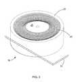
- FIG. 1is a perspective view of a inductive heater humidifier in accordance with the present invention
- FIG. 2is an exploded perspective view of a ferrite base shown in FIG. 1 ;
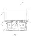
- FIG. 3is an exploded perspective view of the ferrite base with a cover plate thereon;
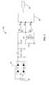
- FIG. 4is a schematic of an electrical circuit according to one form of the present invention.
- FIG. 5is a schematic of the electrical circuit according to an alternative form of the present invention.
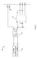
- FIG. 6is a schematic of a control circuit according to one form of the present invention.
- FIG. 7is a perspective view of the inductive heater humidifier illustrating a magnetic flux path.
- the humidifier 10comprises a reservoir 12 for storing fluid such as water.
- the reservoir 12includes a removable bottom plate 14 composed of a ferromagnetic material such as, but not limited to, stainless steel (e.g., 430 stainless steel), iron, cobalt, nickel, and/or alloys thereof.
- the bottom plate 14may include a biocompatible coating such as Titanium Dioxide (TiO 2 ) and is disposed on a non-metallic cover plate 16 resting on a topless ferrite base 18 .
- the cover plate 16may be composed of glass and/or various polymers such as acrylic.
- the ferrite base 18is composed of a material exhibiting hysteretic low energy losses at high frequencies.
- the ferrite base 18is composed of a sintered powdered ferrite.
- the ferrite base 18is composed of a material having high magnetic permeability to provide a path of least resistance for a magnetic flux.
- the ferrite base 18may be composed of an electrically non-conductive material, or a material having low electrical conductivity such that eddy currents are sufficiently minimized.
- the ferrite base 18should include a material having a magnetization that can easily reverse direction without dissipating much energy (hysteresis losses), and having a high resistivity to prevent eddy currents in the core.
- the ferrite base 18may include a ferrous oxide having a transition metal such as, but not limited to, iron, nickel, manganese, or zinc.
- the ferrite base 18may include a ferrite such as manganese-zinc (MnZn), which exhibits magnetic permeability at about 100°-150° Celsius at frequencies above about 20-100 kHz.
- the ferrite base 18may also include a ferrite such as nickel-zinc (NiZn).
- the ferrite base 18includes a central core 20 separated from a peripheral sidewall 22 to form a channel or cavity 24 there between. While the ferrite base 18 is shown in the drawings as being circular, it is to be understood that the ferrite base 18 may be of any suitable shape.
- the ferrite base 18further includes insulated magnetic coil disposed within the cavity 24 and wound around the central core 20 to form an induction coil 26 for generating heat. As best shown in FIG. 2 , the ferrite base 18 may include a slit 28 for managing the induction coil 26 and reducing eddy currents circulating in the ferrite.
- the height of the induction coil 26may be such that it is flush against the bottom surface of the cover plate 16 .
- the ferrite base 18encloses the induction coil 26 on all sides except that facing the cover plate 16 , such that the induction coil 26 is sufficiently insulated.
- the insulation of the magnetic wiremay be sufficient, those of skill in the art will appreciate that the induction coil 26 may be further covered with a thin protective layer for added insulation.
- the electrical circuit 30is operatively connected to the induction coil 26 (schematically depicted by components M 1 and R 1 ) and is operable to supply electrical current thereto.
- the electrical circuit 30includes a power source 32 such as an unregulated DC power supply having full wave rectification of an AC line.
- the power source 32is operable to pass power through a half-bridge rectifier 34 , which is then filtered with one or more capacitors (e.g., C 1 -C 4 ), an inductor L 1 , and/or a common-mode transformer M 1 , which may be connected to a resistor R 1 .
- the electrical circuit 30includes a switching circuit including at least one switching element such as transistors T 1 and T 2 .
- the transistors T 1 and T 2may be metal-oxide-semiconductor field-effect transistors (MOSFETs), insulated gate bipolar transistors (IGBTs), or any other suitable semiconductor switching elements known to those of skill in the art.
- MOSFETsmetal-oxide-semiconductor field-effect transistors
- IGBTsinsulated gate bipolar transistors
- the transistors T 1 and T 2are connected in series with the induction coil 26 and the DC power supply 32 , and may be driven by any suitable control circuit 38 .
- the electrical circuit 30further includes a power factor correction (PFC) circuit 40 , as shown in FIG. 5 .
- the PFC circuit 40includes at least one capacitor (e.g., C 5 and C 6 ) and at least one resistor (e.g., R 2 -R 4 ), which are electrically connected to a common-mode transformer M 2 .
- the PFC circuit 40is operable to filter the input power prior to passing it through the rectifier 34 .
- the control circuit 38includes an oscillator 42 that interfaces with transistors T 1 and T 2 via nodes N 1 -N 3 .
- the control circuit 38also includes an input 44 operable to communicate a control signal to pin P 1 for powering the oscillator 42 on and off.
- an optoelectronic oscillator 46is provided for communicating the control signal to the oscillator 42 , yet those of ordinary skill in the art will appreciate that other suitable components such as a switch or relay may be employed for applying and removing power to pin P 1 .
- the oscillator 42drives transistors T 1 and T 2 , which sequentially fire signals to energize the induction coil 26 .
- the electrical circuit 30 and control circuit 38 described above and shown in FIGS. 4-6are merely intended for purposes of illustration, as those of ordinary skill in the art will appreciate that the electrical and control circuit 30 and 38 may employ various electrical components. Similarly, the electrical and control circuit 30 and 38 may include more or less capacitors, resistors, inductors, switching elements, etc. In addition, while the electrical circuit 30 is preferably controlled by a self-oscillating half-bridge driver such as that shown in FIG. 6 , alternative controllers known in the art may be employed.
- AC current received from the power source 32is converted to DC using the rectifier 34 .
- the electrical circuit 30includes a PFC circuit 40
- the AC currentis filtered prior to being passed to through the rectifier 34 .
- the DC currentis filtered with at least one capacitor (e.g., C 1 -C 4 ), inductor L 1 , and/or transformer M 1 , and eventually communicated to the switching circuit (T 1 and T 2 or RL 1 and RL 2 ) to be administered to the induction coil 26 .
- the currentis supplied at a frequency outside the audible range of humans.
- the input voltage of the power source 32should be converted to a frequency tuned to the bottom plate 14 of the reservoir 12 .
- the induction coil 26Once energized, the induction coil 26 generates eddy currents and alternating magnetic polarizations, which in turn, produce heat. More specifically, when the induction coil 26 is energized, magnetic flux circulates primarily in a path constrained by the ferrite central core 20 and the ferromagnetic bottom plate 14 above it, which is also magnetically permeable. Flux circulating through the bottom plate 14 produces heat because unlike the central core 20 , the bottom plate 14 is composed of a material having high-loss properties. Since the bottom plate 14 is integral to the reservoir 12 , it remains relatively cool while heat generated from eddy currents and hysteresis is efficiently transferred to the fluid within the reservoir 12 via convection. In addition, the exterior of the reservoir 12 , including all surrounding structures, remain cool since they are not electrically conductive.
- the magnetic fluxremains primarily in the ferromagnetic components (e.g., the ferrite base 18 and bottom plate 14 ) since the magnetic permeability of the ferrite base 18 , the central core 20 , and the ferromagnetic bottom plate 14 are much greater than any nearby materials.
- the ferrite base 18is composed of a magnetically permeable material, a path of least resistance is provided for the magnetic flux. As best shown in FIG. 7 , the path of magnetic flux from the induction coil 26 flows upward through the center of the ferrite base 18 , then outwards, and returns down through the sidewall 22 of the ferrite base 18 and back inwards towards the center.
- the humidifier 10As understood by those of skill in the art, efficient operation of the humidifier 10 is ensured by maximizing hysteretic and eddy current losses, while also minimizing stray magnetic fields and maintaining a cool central core 20 . Furthermore, operation of the humidifier 10 should be restricted to temperatures below the ferromagnetic curie point of the bottom plate 14 of the reservoir so that magnetic domains within the bottom plate 14 are oscillated as well to produce additional heat.
- a method of operating an induction heater humidifier 10comprises energizing an induction coil 26 disposed within a ferrite base 18 .
- the induction coil 26may be energized using an electrical circuit 30 having a half-bridge rectifier 34 driven by a high frequency oscillator 38 .
- the induction coil 26produces eddy currents and alternating magnetic polarizations.
- the methodfurther includes directing the heat generated from the induction coil 26 to a reservoir base, such as the ferromagnetic bottom plate 14 .
- the methodincludes restricting the operating temperature of the induction heater humidifier 10 to below a ferromagnetic curie point of the reservoir base in order to oscillate magnetic domains within the bottom plate 14 to generate additional heat.
- the present disclosureprovides an induction heater humidifier capable of rapid heating and transferring considerable power to a target to be heated without generating excessive temperature in the exciter.
- the humidifieremploys high frequency induction to transfer heat directly to a water reservoir, numerous thermal barriers that normally exist between self-contained heathers and the targeted objects may be eliminated. As such, the present disclosure helps achieve greater efficiency while reducing overall costs.
Landscapes
- Engineering & Computer Science (AREA)
- Chemical & Material Sciences (AREA)
- Combustion & Propulsion (AREA)
- Mechanical Engineering (AREA)
- General Engineering & Computer Science (AREA)
- Physics & Mathematics (AREA)
- Electromagnetism (AREA)
- General Induction Heating (AREA)
Abstract
Description
Claims (23)
Priority Applications (6)
| Application Number | Priority Date | Filing Date | Title |
|---|---|---|---|
| US12/794,571US8476562B2 (en) | 2010-06-04 | 2010-06-04 | Inductive heater humidifier |
| AU2011261333AAU2011261333B2 (en) | 2010-06-04 | 2011-06-03 | Inductive heater humidifier |
| ES11725586TES2753162T3 (en) | 2010-06-04 | 2011-06-03 | Inductive heater humidifier |
| PCT/US2011/039021WO2011153407A1 (en) | 2010-06-04 | 2011-06-03 | Inductive heater humidifier |
| EP11725586.9AEP2578057B1 (en) | 2010-06-04 | 2011-06-03 | Inductive heater humidifier |
| CN201180034956.8ACN103004285B (en) | 2010-06-04 | 2011-06-03 | Induction heating type humidifier |
Applications Claiming Priority (1)
| Application Number | Priority Date | Filing Date | Title |
|---|---|---|---|
| US12/794,571US8476562B2 (en) | 2010-06-04 | 2010-06-04 | Inductive heater humidifier |
Publications (2)
| Publication Number | Publication Date |
|---|---|
| US20110297668A1 US20110297668A1 (en) | 2011-12-08 |
| US8476562B2true US8476562B2 (en) | 2013-07-02 |
Family
ID=44315370
Family Applications (1)
| Application Number | Title | Priority Date | Filing Date |
|---|---|---|---|
| US12/794,571Active2031-08-31US8476562B2 (en) | 2010-06-04 | 2010-06-04 | Inductive heater humidifier |
Country Status (6)
| Country | Link |
|---|---|
| US (1) | US8476562B2 (en) |
| EP (1) | EP2578057B1 (en) |
| CN (1) | CN103004285B (en) |
| AU (1) | AU2011261333B2 (en) |
| ES (1) | ES2753162T3 (en) |
| WO (1) | WO2011153407A1 (en) |
Cited By (1)
| Publication number | Priority date | Publication date | Assignee | Title |
|---|---|---|---|---|
| US10660163B2 (en) | 2015-12-11 | 2020-05-19 | Dri-Steem Corporation | Induction steam humidifier with replaceable canister |
Families Citing this family (7)
| Publication number | Priority date | Publication date | Assignee | Title |
|---|---|---|---|---|
| US10645763B2 (en) | 2013-02-19 | 2020-05-05 | Illinois Tool Works Inc. | Induction heating head |
| US20160095170A1 (en)* | 2014-09-29 | 2016-03-31 | Jane Sunghee Kim | Paper cookware |
| EP3324703B1 (en)* | 2016-11-18 | 2024-08-07 | Kendrion Kuhnke Automation GmbH | Induction heating device for industrial purposes |
| US11576424B2 (en)* | 2017-04-05 | 2023-02-14 | Altria Client Services Llc | Susceptor for use with an inductively heated aerosol-generating device or system |
| KR20230169389A (en) | 2017-04-05 | 2023-12-15 | 필립모리스 프로덕츠 에스.에이. | Susceptor for use with an inductively heated aerosol-generating device or system |
| CN109140639A (en)* | 2018-06-30 | 2019-01-04 | 湖南明康中锦医疗科技发展有限公司 | Humidifier and humidity control method |
| CN112006810B (en)* | 2020-09-21 | 2022-04-29 | 谭健荣 | Pretreatment equipment before implantation of artificial blood vessel operation |
Citations (30)
| Publication number | Priority date | Publication date | Assignee | Title |
|---|---|---|---|---|
| US4371768A (en)* | 1979-10-23 | 1983-02-01 | Tetra Pak International Ab | Arrangement for the sealing of thermoplastic-coated packing material |
| US4792652A (en)* | 1986-12-10 | 1988-12-20 | Electricite De France - Service National | Electric induction cooking appliance with reduced harmonic emission |
| US5053593A (en) | 1989-01-23 | 1991-10-01 | Nikko Corporation Ltd. | Low-frequency electromagnetic induction heater |
| US5222185A (en) | 1992-03-26 | 1993-06-22 | Mccord Jr Harry C | Portable water heater utilizing combined fluid-in-circuit and induction heating effects |
| US5286942A (en) | 1991-10-24 | 1994-02-15 | Arthur D. Little Enterprises, Inc. | Induction steam humidifier |
| US5450305A (en)* | 1991-08-12 | 1995-09-12 | Auckland Uniservices Limited | Resonant power supplies |
| JPH07318119A (en) | 1994-05-19 | 1995-12-08 | Sanden Corp | Air heating humidifier |
| WO1996013138A1 (en) | 1994-10-24 | 1996-05-02 | Matsushita Electric Industrial Co., Ltd. | Steam generating apparatus of induction heating system |
| US5525782A (en) | 1993-11-11 | 1996-06-11 | Matsushita Electric Industrial Co., Ltd. | Electric combination oven with humidity conditioner |
| US5801359A (en) | 1994-07-08 | 1998-09-01 | Canon Kabushiki Kaisha | Temperature control that defects voltage drop across excitation coil in image heating apparatus |
| US6040564A (en) | 1995-10-04 | 2000-03-21 | Matsushita Electric Indutrial Co., Ltd. | Microwave heating apparatus and microwave heating method |
| US6084225A (en)* | 1999-05-17 | 2000-07-04 | The Lepel Corporation | RF induction coil |
| EP1055884A2 (en) | 1999-05-28 | 2000-11-29 | The Holmes Group, Inc. | Humidifier having induction heating system |
| JP2000346409A (en) | 1999-06-10 | 2000-12-15 | Tiger Vacuum Bottle Co Ltd | humidifier |
| JP2001161564A (en) | 1999-09-30 | 2001-06-19 | Chubu Corporation | Electromagnetic induction heating type steamer |
| JP2001174009A (en) | 1999-12-14 | 2001-06-29 | Daikin Ind Ltd | Humidity controller |
| US6320169B1 (en) | 1999-09-07 | 2001-11-20 | Thermal Solutions, Inc. | Method and apparatus for magnetic induction heating using radio frequency identification of object to be heated |
| US20030020586A1 (en)* | 2001-07-30 | 2003-01-30 | Fuji Xerox Co., Ltd. | Magnetic core, magnetic field shield member, and electrophotographic apparatus using them |
| US20030230567A1 (en) | 2002-06-12 | 2003-12-18 | Steris Inc. | Vaporizer using electrical induction to produce heat |
| US6681998B2 (en) | 2000-12-22 | 2004-01-27 | Chrysalis Technologies Incorporated | Aerosol generator having inductive heater and method of use thereof |
| US20040037597A1 (en) | 2002-08-20 | 2004-02-26 | Fuji Xerox Co., Ltd. | Magnetic core and magnetic field shield member,and excitation coil, transformer, electric equipment, and electrophotographic apparatuses using the magnetic core and the magnetic field shield member |
| US6770857B2 (en) | 2002-03-01 | 2004-08-03 | Matsushita Electric Industrial Co., Ltd. | Induction heating apparatus |
| US6844533B1 (en)* | 2003-08-29 | 2005-01-18 | Ksp Technologies Corp. | Induction heating apparatus |
| US20070108201A1 (en) | 2005-04-22 | 2007-05-17 | Vinegar Harold J | Insulated conductor temperature limited heater for subsurface heating coupled in a three-phase wye configuration |
| WO2007101298A1 (en) | 2006-03-09 | 2007-09-13 | Resmed Ltd | Induction heating system and method for humidifier |
| WO2008054070A1 (en) | 2006-11-03 | 2008-05-08 | Sung Il Kim | A heating apparatus and luminous apparatus using induction heating |
| US20080217321A1 (en) | 2005-04-22 | 2008-09-11 | Vinegar Harold J | Temperature limited heater utilizing non-ferromagnetic conductor |
| EP1978786A1 (en) | 2006-02-02 | 2008-10-08 | Matsushita Electric Industrial Co., Ltd. | Induction heating apparatus |
| JP2009079887A (en) | 2007-09-07 | 2009-04-16 | Sharp Corp | Cooker |
| US20100147299A1 (en)* | 2007-06-05 | 2010-06-17 | Resmed Limited | Electrical heater with particular application to humidification and fluid warming |
Family Cites Families (2)
| Publication number | Priority date | Publication date | Assignee | Title |
|---|---|---|---|---|
| JP3724857B2 (en)* | 1995-09-18 | 2005-12-07 | 株式会社瀬田技研 | Temperature control device and start method for electromagnetic induction heating device |
| US20090084776A1 (en)* | 2007-10-02 | 2009-04-02 | Chuan-Pan Huang | Induction device for a humidifier |
- 2010
- 2010-06-04USUS12/794,571patent/US8476562B2/enactiveActive
- 2011
- 2011-06-03AUAU2011261333Apatent/AU2011261333B2/enactiveActive
- 2011-06-03WOPCT/US2011/039021patent/WO2011153407A1/enactiveApplication Filing
- 2011-06-03CNCN201180034956.8Apatent/CN103004285B/ennot_activeExpired - Fee Related
- 2011-06-03ESES11725586Tpatent/ES2753162T3/enactiveActive
- 2011-06-03EPEP11725586.9Apatent/EP2578057B1/enactiveActive
Patent Citations (33)
| Publication number | Priority date | Publication date | Assignee | Title |
|---|---|---|---|---|
| US4371768A (en)* | 1979-10-23 | 1983-02-01 | Tetra Pak International Ab | Arrangement for the sealing of thermoplastic-coated packing material |
| US4792652A (en)* | 1986-12-10 | 1988-12-20 | Electricite De France - Service National | Electric induction cooking appliance with reduced harmonic emission |
| US5053593A (en) | 1989-01-23 | 1991-10-01 | Nikko Corporation Ltd. | Low-frequency electromagnetic induction heater |
| US5450305A (en)* | 1991-08-12 | 1995-09-12 | Auckland Uniservices Limited | Resonant power supplies |
| US5286942A (en) | 1991-10-24 | 1994-02-15 | Arthur D. Little Enterprises, Inc. | Induction steam humidifier |
| US5222185A (en) | 1992-03-26 | 1993-06-22 | Mccord Jr Harry C | Portable water heater utilizing combined fluid-in-circuit and induction heating effects |
| US5525782A (en) | 1993-11-11 | 1996-06-11 | Matsushita Electric Industrial Co., Ltd. | Electric combination oven with humidity conditioner |
| JPH07318119A (en) | 1994-05-19 | 1995-12-08 | Sanden Corp | Air heating humidifier |
| US5801359A (en) | 1994-07-08 | 1998-09-01 | Canon Kabushiki Kaisha | Temperature control that defects voltage drop across excitation coil in image heating apparatus |
| WO1996013138A1 (en) | 1994-10-24 | 1996-05-02 | Matsushita Electric Industrial Co., Ltd. | Steam generating apparatus of induction heating system |
| US6008482A (en) | 1994-10-24 | 1999-12-28 | Matsushita Electric Industrial Co., Ltd. | Microwave oven with induction steam generating apparatus |
| US6040564A (en) | 1995-10-04 | 2000-03-21 | Matsushita Electric Indutrial Co., Ltd. | Microwave heating apparatus and microwave heating method |
| US6084225A (en)* | 1999-05-17 | 2000-07-04 | The Lepel Corporation | RF induction coil |
| US6335517B1 (en) | 1999-05-28 | 2002-01-01 | The Holmes Group, Inc. | Humidifier having induction heating system |
| EP1055884A2 (en) | 1999-05-28 | 2000-11-29 | The Holmes Group, Inc. | Humidifier having induction heating system |
| JP2000346409A (en) | 1999-06-10 | 2000-12-15 | Tiger Vacuum Bottle Co Ltd | humidifier |
| US6320169B1 (en) | 1999-09-07 | 2001-11-20 | Thermal Solutions, Inc. | Method and apparatus for magnetic induction heating using radio frequency identification of object to be heated |
| JP2001161564A (en) | 1999-09-30 | 2001-06-19 | Chubu Corporation | Electromagnetic induction heating type steamer |
| JP2001174009A (en) | 1999-12-14 | 2001-06-29 | Daikin Ind Ltd | Humidity controller |
| US6681998B2 (en) | 2000-12-22 | 2004-01-27 | Chrysalis Technologies Incorporated | Aerosol generator having inductive heater and method of use thereof |
| US20030020586A1 (en)* | 2001-07-30 | 2003-01-30 | Fuji Xerox Co., Ltd. | Magnetic core, magnetic field shield member, and electrophotographic apparatus using them |
| US6668151B2 (en) | 2001-07-30 | 2003-12-23 | Fuji Xerox Co., Ltd. | Magnetic core, magnetic field shield member, and electrophotographic apparatus using them |
| US6770857B2 (en) | 2002-03-01 | 2004-08-03 | Matsushita Electric Industrial Co., Ltd. | Induction heating apparatus |
| US20030230567A1 (en) | 2002-06-12 | 2003-12-18 | Steris Inc. | Vaporizer using electrical induction to produce heat |
| US20040037597A1 (en) | 2002-08-20 | 2004-02-26 | Fuji Xerox Co., Ltd. | Magnetic core and magnetic field shield member,and excitation coil, transformer, electric equipment, and electrophotographic apparatuses using the magnetic core and the magnetic field shield member |
| US6844533B1 (en)* | 2003-08-29 | 2005-01-18 | Ksp Technologies Corp. | Induction heating apparatus |
| US20070108201A1 (en) | 2005-04-22 | 2007-05-17 | Vinegar Harold J | Insulated conductor temperature limited heater for subsurface heating coupled in a three-phase wye configuration |
| US20080217321A1 (en) | 2005-04-22 | 2008-09-11 | Vinegar Harold J | Temperature limited heater utilizing non-ferromagnetic conductor |
| EP1978786A1 (en) | 2006-02-02 | 2008-10-08 | Matsushita Electric Industrial Co., Ltd. | Induction heating apparatus |
| WO2007101298A1 (en) | 2006-03-09 | 2007-09-13 | Resmed Ltd | Induction heating system and method for humidifier |
| WO2008054070A1 (en) | 2006-11-03 | 2008-05-08 | Sung Il Kim | A heating apparatus and luminous apparatus using induction heating |
| US20100147299A1 (en)* | 2007-06-05 | 2010-06-17 | Resmed Limited | Electrical heater with particular application to humidification and fluid warming |
| JP2009079887A (en) | 2007-09-07 | 2009-04-16 | Sharp Corp | Cooker |
Cited By (1)
| Publication number | Priority date | Publication date | Assignee | Title |
|---|---|---|---|---|
| US10660163B2 (en) | 2015-12-11 | 2020-05-19 | Dri-Steem Corporation | Induction steam humidifier with replaceable canister |
Also Published As
| Publication number | Publication date |
|---|---|
| AU2011261333A1 (en) | 2013-01-10 |
| EP2578057B1 (en) | 2019-08-07 |
| CN103004285A (en) | 2013-03-27 |
| EP2578057A1 (en) | 2013-04-10 |
| WO2011153407A1 (en) | 2011-12-08 |
| AU2011261333B2 (en) | 2013-07-25 |
| US20110297668A1 (en) | 2011-12-08 |
| ES2753162T3 (en) | 2020-04-07 |
| CN103004285B (en) | 2015-09-16 |
Similar Documents
| Publication | Publication Date | Title |
|---|---|---|
| US8476562B2 (en) | Inductive heater humidifier | |
| RU2670766C9 (en) | Device for evaporation volatile liquid | |
| RU2670765C9 (en) | Device for evaporating volatile substance | |
| RU2636164C2 (en) | Device for volatile material evaporation | |
| TWI264239B (en) | Method and apparatus for temperature control of an object | |
| EP1350415A4 (en) | INDUCTION OVEN WITH COIL SYSTEM WITH IMPROVED EFFICIENCY | |
| Li et al. | A novel domestic SE-IH with high induction efficiency and compatibility of nonferromagnetic vessels | |
| Aoyama et al. | Proposal and challenge of Halbach array type induction coil for cooktop applications | |
| JP4555838B2 (en) | Induction heating device | |
| JPH10302953A (en) | Induction heating device | |
| JP3123073U (en) | Electromagnetic induction heating radiator with U-shaped magnetic core | |
| JP5103782B2 (en) | rice cooker | |
| US20240244721A1 (en) | Induction heating type cooktop | |
| JP2000340352A (en) | Electromagnetic induction heating device | |
| JPH10223365A (en) | Induction heating cooker | |
| JP3925388B2 (en) | Induction heating device | |
| CN212519482U (en) | A magnetoelectric integrated low-profile induction cooker coil structure | |
| JP2008253434A5 (en) | ||
| WO2008072804A1 (en) | Heating coil in induction heating cooking apparatus | |
| CN109219178B (en) | electromagnetic induction rice cooker | |
| KR102733388B1 (en) | Induction heating type cooktop | |
| Patil et al. | Induction heating as fluid geyser | |
| JP2002043044A (en) | Heating coil for induction heating device | |
| RU2267868C1 (en) | Flowing inductive liquid heater | |
| KR20250030801A (en) | Cooking appliance |
Legal Events
| Date | Code | Title | Description |
|---|---|---|---|
| AS | Assignment | Owner name:WATLOW ELECTRIC MANUFACTURING COMPANY, MISSOURI Free format text:ASSIGNMENT OF ASSIGNORS INTEREST;ASSIGNOR:SWANSON, CAL;REEL/FRAME:024793/0531 Effective date:20100528 | |
| STCF | Information on status: patent grant | Free format text:PATENTED CASE | |
| AS | Assignment | Owner name:PANTELEEV, MILEN K., BULGARIA Free format text:ASSIGNMENT OF ASSIGNORS INTEREST;ASSIGNOR:SHABAN, YASSER R.;REEL/FRAME:031363/0028 Effective date:20130920 | |
| FPAY | Fee payment | Year of fee payment:4 | |
| MAFP | Maintenance fee payment | Free format text:PAYMENT OF MAINTENANCE FEE, 8TH YEAR, LARGE ENTITY (ORIGINAL EVENT CODE: M1552); ENTITY STATUS OF PATENT OWNER: LARGE ENTITY Year of fee payment:8 | |
| AS | Assignment | Owner name:BANK OF MONTREAL, AS ADMINISTRATIVE AGENT, ILLINOIS Free format text:PATENT SECURITY AGREEMENT (SHORT FORM);ASSIGNOR:WATLOW ELECTRIC MANUFACTURING COMPANY;REEL/FRAME:055479/0708 Effective date:20210302 | |
| MAFP | Maintenance fee payment | Free format text:PAYMENT OF MAINTENANCE FEE, 12TH YEAR, LARGE ENTITY (ORIGINAL EVENT CODE: M1553); ENTITY STATUS OF PATENT OWNER: LARGE ENTITY Year of fee payment:12 |