US8475500B2 - Multi-axial spinal fixation system - Google Patents
Multi-axial spinal fixation systemDownload PDFInfo
- Publication number
- US8475500B2 US8475500B2US11/762,898US76289807AUS8475500B2US 8475500 B2US8475500 B2US 8475500B2US 76289807 AUS76289807 AUS 76289807AUS 8475500 B2US8475500 B2US 8475500B2
- Authority
- US
- United States
- Prior art keywords
- yoke
- socket
- rod
- insert
- fastener
- Prior art date
- Legal status (The legal status is an assumption and is not a legal conclusion. Google has not performed a legal analysis and makes no representation as to the accuracy of the status listed.)
- Expired - Fee Related, expires
Links
Images


Classifications
- A—HUMAN NECESSITIES
- A61—MEDICAL OR VETERINARY SCIENCE; HYGIENE
- A61B—DIAGNOSIS; SURGERY; IDENTIFICATION
- A61B17/00—Surgical instruments, devices or methods
- A61B17/56—Surgical instruments or methods for treatment of bones or joints; Devices specially adapted therefor
- A61B17/58—Surgical instruments or methods for treatment of bones or joints; Devices specially adapted therefor for osteosynthesis, e.g. bone plates, screws or setting implements
- A61B17/68—Internal fixation devices, including fasteners and spinal fixators, even if a part thereof projects from the skin
- A61B17/70—Spinal positioners or stabilisers, e.g. stabilisers comprising fluid filler in an implant
- A61B17/7001—Screws or hooks combined with longitudinal elements which do not contact vertebrae
- A61B17/7035—Screws or hooks, wherein a rod-clamping part and a bone-anchoring part can pivot relative to each other
- A61B17/7037—Screws or hooks, wherein a rod-clamping part and a bone-anchoring part can pivot relative to each other wherein pivoting is blocked when the rod is clamped
- A—HUMAN NECESSITIES
- A61—MEDICAL OR VETERINARY SCIENCE; HYGIENE
- A61B—DIAGNOSIS; SURGERY; IDENTIFICATION
- A61B17/00—Surgical instruments, devices or methods
- A61B17/56—Surgical instruments or methods for treatment of bones or joints; Devices specially adapted therefor
- A61B17/58—Surgical instruments or methods for treatment of bones or joints; Devices specially adapted therefor for osteosynthesis, e.g. bone plates, screws or setting implements
- A61B17/68—Internal fixation devices, including fasteners and spinal fixators, even if a part thereof projects from the skin
- A61B17/70—Spinal positioners or stabilisers, e.g. stabilisers comprising fluid filler in an implant
- A61B17/7001—Screws or hooks combined with longitudinal elements which do not contact vertebrae
- A61B17/7002—Longitudinal elements, e.g. rods
- A—HUMAN NECESSITIES
- A61—MEDICAL OR VETERINARY SCIENCE; HYGIENE
- A61B—DIAGNOSIS; SURGERY; IDENTIFICATION
- A61B17/00—Surgical instruments, devices or methods
- A61B17/56—Surgical instruments or methods for treatment of bones or joints; Devices specially adapted therefor
- A61B17/58—Surgical instruments or methods for treatment of bones or joints; Devices specially adapted therefor for osteosynthesis, e.g. bone plates, screws or setting implements
- A61B17/68—Internal fixation devices, including fasteners and spinal fixators, even if a part thereof projects from the skin
- A61B17/70—Spinal positioners or stabilisers, e.g. stabilisers comprising fluid filler in an implant
- A61B17/7001—Screws or hooks combined with longitudinal elements which do not contact vertebrae
- A61B17/7032—Screws or hooks with U-shaped head or back through which longitudinal rods pass
- A—HUMAN NECESSITIES
- A61—MEDICAL OR VETERINARY SCIENCE; HYGIENE
- A61B—DIAGNOSIS; SURGERY; IDENTIFICATION
- A61B17/00—Surgical instruments, devices or methods
- A61B17/56—Surgical instruments or methods for treatment of bones or joints; Devices specially adapted therefor
- A61B17/58—Surgical instruments or methods for treatment of bones or joints; Devices specially adapted therefor for osteosynthesis, e.g. bone plates, screws or setting implements
- A61B17/68—Internal fixation devices, including fasteners and spinal fixators, even if a part thereof projects from the skin
- A61B17/70—Spinal positioners or stabilisers, e.g. stabilisers comprising fluid filler in an implant
- A61B17/7074—Tools specially adapted for spinal fixation operations other than for bone removal or filler handling
- A61B17/7076—Tools specially adapted for spinal fixation operations other than for bone removal or filler handling for driving, positioning or assembling spinal clamps or bone anchors specially adapted for spinal fixation
- A61B17/7082—Tools specially adapted for spinal fixation operations other than for bone removal or filler handling for driving, positioning or assembling spinal clamps or bone anchors specially adapted for spinal fixation for driving, i.e. rotating, screws or screw parts specially adapted for spinal fixation, e.g. for driving polyaxial or tulip-headed screws
- A—HUMAN NECESSITIES
- A61—MEDICAL OR VETERINARY SCIENCE; HYGIENE
- A61B—DIAGNOSIS; SURGERY; IDENTIFICATION
- A61B17/00—Surgical instruments, devices or methods
- A61B17/56—Surgical instruments or methods for treatment of bones or joints; Devices specially adapted therefor
- A61B17/58—Surgical instruments or methods for treatment of bones or joints; Devices specially adapted therefor for osteosynthesis, e.g. bone plates, screws or setting implements
- A61B17/68—Internal fixation devices, including fasteners and spinal fixators, even if a part thereof projects from the skin
- A61B17/70—Spinal positioners or stabilisers, e.g. stabilisers comprising fluid filler in an implant
- A61B17/7074—Tools specially adapted for spinal fixation operations other than for bone removal or filler handling
- A61B17/7083—Tools for guidance or insertion of tethers, rod-to-anchor connectors, rod-to-rod connectors, or longitudinal elements
- A61B17/7086—Rod reducers, i.e. devices providing a mechanical advantage to allow a user to force a rod into or onto an anchor head other than by means of a rod-to-bone anchor locking element; rod removers
- A—HUMAN NECESSITIES
- A61—MEDICAL OR VETERINARY SCIENCE; HYGIENE
- A61B—DIAGNOSIS; SURGERY; IDENTIFICATION
- A61B17/00—Surgical instruments, devices or methods
- A61B17/56—Surgical instruments or methods for treatment of bones or joints; Devices specially adapted therefor
- A61B17/58—Surgical instruments or methods for treatment of bones or joints; Devices specially adapted therefor for osteosynthesis, e.g. bone plates, screws or setting implements
- A61B17/68—Internal fixation devices, including fasteners and spinal fixators, even if a part thereof projects from the skin
- A61B17/84—Fasteners therefor or fasteners being internal fixation devices
- A61B17/86—Pins or screws or threaded wires; nuts therefor
- A61B17/8605—Heads, i.e. proximal ends projecting from bone
- A—HUMAN NECESSITIES
- A61—MEDICAL OR VETERINARY SCIENCE; HYGIENE
- A61B—DIAGNOSIS; SURGERY; IDENTIFICATION
- A61B17/00—Surgical instruments, devices or methods
- A61B17/56—Surgical instruments or methods for treatment of bones or joints; Devices specially adapted therefor
- A61B17/58—Surgical instruments or methods for treatment of bones or joints; Devices specially adapted therefor for osteosynthesis, e.g. bone plates, screws or setting implements
- A61B17/68—Internal fixation devices, including fasteners and spinal fixators, even if a part thereof projects from the skin
- A61B17/84—Fasteners therefor or fasteners being internal fixation devices
- A61B17/86—Pins or screws or threaded wires; nuts therefor
- A61B17/8685—Pins or screws or threaded wires; nuts therefor comprising multiple separate parts
- A—HUMAN NECESSITIES
- A61—MEDICAL OR VETERINARY SCIENCE; HYGIENE
- A61B—DIAGNOSIS; SURGERY; IDENTIFICATION
- A61B17/00—Surgical instruments, devices or methods
- A61B17/56—Surgical instruments or methods for treatment of bones or joints; Devices specially adapted therefor
- A61B17/58—Surgical instruments or methods for treatment of bones or joints; Devices specially adapted therefor for osteosynthesis, e.g. bone plates, screws or setting implements
- A61B17/88—Osteosynthesis instruments; Methods or means for implanting or extracting internal or external fixation devices
- B—PERFORMING OPERATIONS; TRANSPORTING
- B25—HAND TOOLS; PORTABLE POWER-DRIVEN TOOLS; MANIPULATORS
- B25B—TOOLS OR BENCH DEVICES NOT OTHERWISE PROVIDED FOR, FOR FASTENING, CONNECTING, DISENGAGING OR HOLDING
- B25B23/00—Details of, or accessories for, spanners, wrenches, screwdrivers
- B25B23/02—Arrangements for handling screws or nuts
- B25B23/08—Arrangements for handling screws or nuts for holding or positioning screw or nut prior to or during its rotation
- B25B23/10—Arrangements for handling screws or nuts for holding or positioning screw or nut prior to or during its rotation using mechanical gripping means
- B25B23/105—Arrangements for handling screws or nuts for holding or positioning screw or nut prior to or during its rotation using mechanical gripping means the gripping device being an integral part of the driving bit
- A—HUMAN NECESSITIES
- A61—MEDICAL OR VETERINARY SCIENCE; HYGIENE
- A61B—DIAGNOSIS; SURGERY; IDENTIFICATION
- A61B17/00—Surgical instruments, devices or methods
- A61B17/56—Surgical instruments or methods for treatment of bones or joints; Devices specially adapted therefor
- A61B17/58—Surgical instruments or methods for treatment of bones or joints; Devices specially adapted therefor for osteosynthesis, e.g. bone plates, screws or setting implements
- A61B17/88—Osteosynthesis instruments; Methods or means for implanting or extracting internal or external fixation devices
- A61B17/8875—Screwdrivers, spanners or wrenches
Definitions
- the present inventionrelates to spinal fixation systems and particularly to an anchor device that incorporates multi-axial fixation to the spine.
- an elongated membersuch as a bendable rod is disposed longitudinally along a length of the spine, spanning two or more vertebral levels.
- the rodis bent to correspond to the normal curvature of the spine in the particular region being instrumented, such as the normal kyphotic curvature of the thoracic region or the lordotic curvature of the lumbar region.
- the rodis engaged to various vertebrae along a length of the spinal column by way of a number of anchor devices that utilize a variety of fixation elements configured to engage specific portions of the vertebra and other bones.
- fixation elementis a hook that is configured to engage the laminae of the vertebra.
- Another very prevalent fixation elementis a screw that can be threaded into various parts of the vertebrae or other bones.
- variable angle screwallows pivoting of the bone screw in a single plane parallel to the plane of the spinal rod.
- One goal achieved by the variable angle screwis that the surgeon can apply vertebral fixation elements to the spine in more appropriate anatomic positions.
- fixation elementshaving a body that defines a slot within which the spinal rod is received.
- the slotincludes a threaded bore into which a threaded plug is engaged to secure the rod within the body of the fixation element.
- fixation elementmay be positioned directly beneath the elongated rod, thereby reducing the overall bulkiness of the implant construct and minimizing trauma to the surrounding tissue.
- An internally threaded receiver memberpivotally supports the bone screw and a spinal rod on top of the spherical projection.
- An inner set screwis tightened into the receiver member to press the spinal rod against the spherical projection to accommodate various angular orientations of the bone screw relative to the rod.
- a similar multi-axial screwis disclosed in U.S. Pat. No. 5,466,237 to Byrd et al., except an outer nut is provided to secure the rod against the head of the bone screw.
- a spherical headed bone screwis supported within separate halves of a receiver member.
- the bottom of the halvesare held together by a retaining ring.
- the top of the receiver halvesare compressed about the bone screw by nuts threaded onto a threaded spinal rod.
- Harms et al.also describes in U.S. Pat. No. 5,207,678 another multi-axial pedicle screw wherein a compression member is provided between the rod and the head of the screw to exert a force on the screw head to lock the screw against the inner spherical surface of the receiver member.
- U.S. Pat. No. 5,797,911 to Sherman et al.in which a U-shaped holder is provided that receives a bone fastener topped with a crown member.
- the holderaccommodates a rod in a channel above the crown member and a compression member above the rod.
- the compression memberpresses on the rod and crown member to lock the fastener against the holder in any of a number of angles in three dimensions with respect to the rod.
- Another system shown in U.S. Pat. No. 5,733,285 to Errico et al.includes a holder having a tapered and colleted portion into which a bone fastener head is inserted.
- a sleeveis provided that translates down around the colleted portion to crush lock the colleted portion around the head of the bone fastener.
- This apparatusis bulky and difficult to manipulate given the external sliding locking mechanism. It is further dependent on the fit of the external sleeve and the relative strength of the collet and its bending and crushing portions for secure locking of the bone fastener head.
- the present inventioncontemplates a spinal fixation system that incorporates multi-axial fixation characteristics in a low-profile, easy to construct anchor device.
- the systemincludes an elongated member, such as a spinal rod, that extends between spinal segments.
- a series of anchor devicesanchor the rod to the spinal segments, with at least some of the anchor devices providing multi-axial fixation.
- the multi-axial anchor deviceincludes a bone engaging fastener that is adapted to engage a portion of the spine.
- the fasteneris a bone screw adapted to be threaded into the pedicle of a vertebra.
- the head of the bone engaging fasteneris provided with a spherical socket facing the spinal rod.
- a ball insert elementis provided that incorporates a spherical surface for variable angular interface with the socket.
- the ball insertis further configured so that the insert may be introduced into the socket and then rotated within the socket so that the spherical surface is juxtaposed to the socket for captive retention therein.
- the sockethas an interior diameter and a smaller diametrical opening communicating therewith.
- the ball insertis configured as a truncated sphere having a spherical diameter slightly less than the interior diameter of the socket.
- a portion of the ball insertis formed to have an outer curved surface defining a cylinder having a maximum diameter less than the spherical diameter of the ball insert and less than the diameter of the socket opening.
- connection to the spinal rodis provided by way of a yoke that is engaged to the ball insert.
- this engagementis accomplished by a threaded bore in the ball insert and a mating threaded stem of the yoke.
- the ball insertis free to swivel in the fastener socket and since the yoke is attached to the ball insert it is thereby also free to move in a multi-axial manner.
- the yokedefines a channel between opposing arms of the yoke, with the channel configured to snugly seat the rod therein.
- a sleeveis provided that fits about an upper portion of the head of the bone engaging fastener. This upper portion provides a spherical surface to interface with a spherical lower cavity of the sleeve so that the sleeve may adapt a range of spherical angles relative to the bone engaging fastener as necessary to accommodate the position of the spinal rod relative thereto.
- the sleeveincludes in one configuration opposing notches to receive and support the rod.
- the yokedoes not itself support the spinal rod, it does support a set screw that is used to clamp the spinal rod to the notches in the sleeve.
- the set screwis carried by a cap that fits over and around the arms of the yoke.
- the set screwis configured to engage internal threads defined in the yoke arms so that as the set screw is driven into the yoke a lower face of the screw contacts the spinal rod to drive it into the sleeve.
- the set screwis supported within the cap so that the screw may rotate independently of the cap.
- the cap and the set screwmay each define opposing grooves for mutually carrying a retaining ring used to fix the set screw against axial movement relative to the cap. The retaining ring does permit relative rotation so the set screw may be used to clamp the spinal rod.
- the angular orientation of the yokeis adjusted relative to the bone engaging fastener to accommodate the position of the spinal rod relative to the portion of the spine.
- this angular orientationis fixed by pressure engagement between the ball insert and the spherical socket of the head of the bone fastener.
- the present inventioncontemplates that the set screw not only operates to firmly clamp the spinal rod within the yoke and against the sleeve, it also generates an array of forces that press the ball insert into the spherical socket.
- the pressure face of the set screwfirst contacts the spinal rod.
- the pressure faceclamps the rod against the sleeve.
- the rodis generally firmly fixed to the yoke, although the yoke itself is not yet firmly fixed to the bone engaging fastener.
- a releasable detentis disposed between the yoke and the head of the fastener.
- the releasable detentis configured to releasably retain the yoke in at least one pre-determined position relative to the fastener.
- the releasable detentis arranged so that the yoke is maintained in axial alignment with the threaded shank of the bone screw as it is driven into the spinal bone.
- the releasable detentmay include a cavity defined within the stem of the yoke and a spring and a retention ball seated within the cavity.
- the springpushes the retention ball outward into contact with spherical surface of the socket in the fastener head.
- the socketmay be provided with a dimple in axial alignment with the threaded shank of the bone screw to establish the pre-determined position for axial alignment of the yoke.
- the releasable detentmay also be configured to provide frictional movement of the yoke relative to the fastener such that the yoke is frictionally maintained in a position relative to the fastener other than the discrete position.
- the frictional force exerted by the releasable detentis sufficient to temporarily hold the yoke in any angular orientation relative to the bone screw. This feature allows for pre-positioning of the rod-receiving channel of the yoke while the spinal rod is being prepared for engagement with the fixation assembly, such as by bending the rod accordingly.
- One benefit of the present inventionis that it provides for solid anchoring between a spinal rod and a bone engaging fastener at variable spherical angles.
- a further benefitis that a common clamping element is provided to clamp the spinal rod and fix the angular position of the anchor device.
- Yet another benefitresides in one aspect of the anchor device that reduces the overall prominence and profile of the components of the device.
- a still further benefitis that the relative angular position of the components may be temporarily held during implantation or in anticipation of engagement with a prepared spinal rod.
- FIG. 1is a transverse view of a portion of a spine with a fixation system utilizing an elongated members engaged between successive vertebrae.
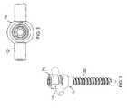
- FIG. 2is a side perspective view of an anchor device according to one embodiment of the invention for use in the fixation system shown in FIG. 1 .
- FIG. 3is a top plan view of the anchor device shown in FIG. 2 .
- FIG. 4is a side cross-sectional view of the anchor device of FIG. 2 .
- FIG. 5is a longitudinal cross-sectional view of the anchor device illustrated in FIG. 2 along the longitudinal axis of the elongated member.
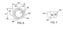
- FIG. 6is a top plan view of a ball insert element of the anchor device shown in FIG. 2 .
- FIG. 7is a side elevational view of the ball insert shown in FIG. 6 .
- FIGS. 8 a - 8 fare side perspective views of a sequence of assembly of the components of the anchor device shown in FIG. 2 .
- FIG. 9is a top perspective view of a sleeve component of the anchor device shown in FIG. 2 .
- FIG. 10is a side cross-sectional view of the sleeve shown in FIG. 9 .
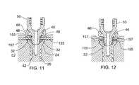
- FIG. 11is a longitudinal cross-sectional view of a fixture with holding pins for holding the position of the ball insert relative to the socket during engagement of the yoke.
- FIG. 12is a longitudinal cross-sectional view of the fixture with holding pins used to crimp or swage the threads of the yoke to fix the yoke to the ball insert.
- FIG. 13is a longitudinal elevational view of a cap with set screw of the anchor device of FIG. 2 .
- FIG. 14is a top plan view of the cap shown in FIG. 13 .
- FIG. 15is a cross-sectional view of the cap of FIG. 14 taken along viewing line XV-XV.
- FIG. 16is a longitudinal cross-sectional view similar to FIG. 5 showing forces generated to lock the components of the anchor device of FIG. 2 .
- FIG. 17is a side elevational view of a fastener inserter tool for use with one embodiment of the anchor device of the present invention.
- FIG. 18is a longitudinal cross-sectional view of the fastener inserter tool shown in FIG. 17 engaged to components of the anchor device of FIG. 2 .
- FIG. 19is a longitudinal cross-sectional view of the lower end of a rod persuader tool engaged to a partially assembled anchor device of FIG. 2 .
- FIG. 20is a longitudinal cross-sectional view of an anchor device according to an alternative embodiment of the invention.
- FIG. 21is a longitudinal cross-sectional view of a screw inserter tool engaged to a partially assembled anchor device, such as the alternative anchor device shown in FIG. 20 .
- FIG. 22is a longitudinal side cross-sectional view of the lower end of the rod persuader tool engaged to a partially assembled modified anchor device, such as the alternative device shown in FIG. 20 .
- the present inventioncontemplates a spinal fixation system, such as the system 10 depicted in FIG. 1 .
- the fixation system 10spans between successive vertebrae of the spine.
- An elongated member, such as rod 12extends along the length of the spine and provides an anchor point for connecting each vertebra to the rod.
- the rodis typically contoured to approximate the normal curvature of the spine for the particular instrumented spinal segments.
- Anchor devices 15are provided for connecting the vertebral segments to the rod. These anchor devices may include hooks, bolts, screws or other means for engaging a vertebra.
- the anchor device 15includes a bone engaging fastener 20 which is a bone screw, as shown in FIG. 2 .
- the bone screw 20includes a threaded shank 22 configured for threaded engagement within a portion of a vertebra.
- the shankis configured for engagement within the pedicle of a vertebra.
- the bone engaging fastener or screw 20further includes a head 24 by which the screw, and ultimately the vertebra, is anchored to the spinal rod 12 .
- the head 24defines a spherical socket 26 with a socket opening 28 facing the rod, as shown in FIGS. 4-5 .
- the bone screw 20further defines a central bore 30 intersecting the socket and extending part way into the threaded shank 22 .
- a transverse bore 32extends through the head 24 and across the socket, as best seen in FIG. 5 . The function of the bores 30 and 32 are discussed herein.
- the head 24includes a spherical outer surface 34 .
- the spherical head 24 of the bone screwis more than simply hemispherical.
- the spherical socket 28subtends a spherical angle of greater than 180 so that socket opening 28 is defined at a chord of the spherical socket.
- the planar diameter of the opening 28 at the chordis less than the inner diameter of the socket.
- the spherical headsubtends a spherical angle of about 240° and the planar chordal diameter of the socket opening 28 is about 90% the spherical diameter of the socket.
- a ball insert element 40illustrated in detail in FIGS. 6-7 .
- the ball insert 40defines a central threaded bore 42 that is provided for connection to a yoke component 50 , as described in more detail herein.
- the ball insertis generally in the form of a truncated sphere, whereby the outer surface 44 of the ball insert includes a spherical surface 45 that is sized to closely approximate the spherical socket 26 , as shown in FIG. 5 .
- spherical surface 45defines an outer spherical diameter D 1 , that is slightly less than the interior diameter of the spherical socket 26 , but greater than the diameter of opening 28 .
- the ball insert 40is further formed to have a cylindrical portion defined by curved surfaces 46 .
- the curved surfaces 46 of cylindrical portiondefine an outer diameter D 2 about axis A as depicted in FIG. 8 b .
- Axis A in one arrangementis formed to be generally perpendicular to the axis of the central threaded bore 42 .
- the maximum diameter D 2is slightly less than the planar chordal diameter of socket opening 28 ( FIG.
- curved surfaces 46are preferably formed to define a cylindrical insert dimension D 2 , it should be appreciated that other configurations may be considered, such as one or more flattened outer surfaces, provided that a maximum insert dimension such as diameter D 2 is formed less than the maximum dimension of the socket opening 28 .
- the ball insert 40is rotated at least 90° so that the insert dimension D 2 with curved surfaces 46 is aligned to pass through planar chordal opening 28 and into the socket 26 .
- the insert dimension D 2is oriented so that axis A of ball insert 40 is essentially aligned along the axis of the bone screw.
- the depth of the socket 26is sufficient to fully receive the rotated ball insert 40 so that the spherical surface 45 exposed in the view of FIG. 8 b is within the socket. Then, in the final step shown in FIG.
- the ball insert 40is further rotated at least 90° so that the threaded bore 42 faces upward through the socket opening 28 .
- the spherical surface 45 of the ball insertis juxtaposed with the interior of the spherical socket 26 , as shown in FIG. 5 , and the ball insert 40 is captively retained in the socket 26 for swivel movement therewithin.
- the ball insert 40is further provided along axis A as seen in FIG. 8 a with a transverse bore 48 that may be aligned with the transverse bore 32 in the spherical head 24 of the bone screw, as shown in FIG. 5 and FIG. 8 a .
- the ball insertis truncated at the top and bottom of the insert.
- the ball insert in this arrangementis not symmetric—i.e., more of the top of the spherical ball is truncated than the bottom of the ball.
- the lower truncated surfacehas indentations 49 as illustrated in FIG. 7 .
- the indentations 49may be directed toward the bottom of socket 26 and are not visible through the socket opening.
- the anchor device 15further includes a yoke 50 having a threaded stem 52 configured to engage the threaded bore 42 in the ball insert 40 .
- the stemis provided with a shoulder 53 that preferably abuts the ball insert 40 when the stem 52 is fully threaded into the bore 42 of the insert.
- the yoke 50includes yoke arms 54 a , 54 b that define a yoke channel 55 therebetween. The gap between the arms 54 a , 54 b , and consequently the width of the channel, is sized to closely fit the spinal rod 12 , as best seen in FIG. 5 .
- the arms 54 a , 54 bdefine internal threads 56 at the upper open end of the yoke 50 for engaging a set screw 80 , as described below.
- a bore 57passes through the threaded stem 52 that is aligned with the bore 30 in the bone screw when the yoke is mounted on the ball insert.
- a sleeve 60is interposed between the yoke 50 and the head 24 of the bone screw 20 .
- the sleeve 60defines a lower cavity 62 that has a spherical configuration to substantially match the spherical outer surface 34 of the screw head 24 .
- Sleeve 60sits on the outer surface 34 for sliding movement thereon, and serves as a clamping element for the rod 12 relative to the yoke as will be described.
- the sleevefurther defines an upper cavity 64 that generally parallels the outer surface of the yoke arms 54 a , 54 b , as seen in FIG. 5 .
- the upper face of the sleeve 60defines opposite rod grooves 66 sized to receive the spinal rod 12 therein.
- the lower face of the sleevedefines opposite notches 68 that are oriented 90° from the rod grooves 66 .
- the notches 68are arranged to align with the transverse bores 32 and 48 when the anchor device is assembled.
- the notches and boresare sized to receive retaining pins 155 ( FIG. 11 ) as described in more detail herein.
- sleeve 60is provided with opposing recessed surfaces 63 that engage the arms 54 a , 54 b of the yoke 50 to key the sleeve 60 to yoke 50 in a manner that allows common swivel movement of the yoke 50 and sleeve 60 relative to the screw head 24 .
- the yoke 50may engage the insert 40 to form an assembly therewith.
- the threaded stem 52 of the yokeis extended through the sleeve 60 with the sleeve keying surfaces 63 aligned with the yoke arms 54 a , 54 b .
- the threaded stem 52is then threaded into engagement with the threaded bore 42 of the ball insert. In order to achieve this threaded engagement it is necessary to hold the ball insert 40 as the stem 52 of the yoke is threaded into the bore 42 .
- the ball insert 40is oriented within the spherical socket 26 so that the transverse bores 48 in the insert are aligned with the transverse bores 32 in the screw head.
- pins 155may be pushed therethrough, taking care that the pins do not extend into the threaded bore 42 , as illustrated in FIG. 11 .
- Arms 157 of a forceps-like toolmay be used to introduce the pins into the bores.
- the sleeve 60may be placed over the head of the bone screw with the notches 68 aligned with the pins 155 .
- the yokeis then extended through the sleeve with the stem engaging the threaded bore 42 of the ball insert.
- the pins 155resist rotation of the ball insert 40 as the stem is threaded into the bore.
- the yoke 50is threaded into the ball insert until the shoulder 53 contacts the upper face of the ball insert 40 as shown in FIGS. 4-5 .
- the pins 155may be used to crimp, swage or deform the threads of the stem 52 of the yoke 50 .
- the tool arms 157may be pressed toward each other so that the pins 155 contact the threaded stem 52 , as shown in FIG. 12 .
- the threadsare distorted the stem 52 of the yoke cannot back out or unthread from the ball insert 40 .
- the pins 155can be removed. It is understood that this initial assembly of the anchor device, namely the steps shown in FIGS. 8 a - 8 e , occur prior to introduction of the anchor device 15 into the spine, preferably by the supplier.
- a cap 70is fitted over the top of the yoke arms 54 a , 54 b .
- the cap 70as further detailed in FIGS. 13-15 , includes a generally cylindrical skirt 74 that fits snugly around the arms 54 a , 54 b to prevent the arms from splaying outward as set screw 80 is threaded into the arms.
- the skirt 74is preferably provided with diametrically opposed flats 75 that correspond to the transverse opening of the yoke channel 55 , as best seen in FIG. 8 f .
- the flats 75define rod grooves 72 that align with, but do not contact, the rod 12 when it is situated within the yoke channel 55 .
- the cap 70includes an upper boss 76 that defines an enlarged circumferential interior groove 78 .
- This grooveis sized to receive a retaining ring or snap ring 90 therein, as seen in FIG. 5 and FIG. 15 .
- the grooveis axially enlarged or lengthened so that the snap ring 90 may translate up and down within the boss 76 for reasons explained below.
- the set screw 80is provided with a threaded stem 82 that is configured to engage the internal threads 56 of the yoke arms 54 a , 54 b .
- the threaded engagement between set screw and yokeare in the form of buttress threads, as depicted in FIGS. 4-5 .
- the buttress threadsminimize the outward force produced as the set screw is threaded into the yoke.
- the use of buttress threadshelp minimize any splaying of the yoke arms that might otherwise occur when the set screw 80 is threaded tightly into the yoke 50 .
- the bottom of the set screwis recessed upwardly of the bottom of the skirt 74 of cap 70 .
- skirt 74also serves as a guide to align the threads 82 of set screw 80 into the threads 56 of the yoke 50 , thereby also reducing the risk of disadvantageous cross-threading.
- the set screw 80includes a pressure face 83 that contacts and exerts a securing force against the spinal rod 12 .
- the pressure face 83 as well as the rod surfacemay exhibit surface features intended to enhance the fixation between set screw and rod, as is known in the art. In particular, a surface roughness may be provided that becomes deformed or cold formed when the set screw is tightened onto the rod. This feature helps prevent the rod from slipping axially (along its length) within the anchor device 15 .
- the set screw 80defines a bore 84 therethrough.
- the upper portion 86 of the boremay be configured to receive a driving tool, such as with hex or TORX surfaces.
- the set screw 80defines a circumferential groove 88 ( FIG. 4 ) configured to receive the retaining ring 90 therein.
- the groove 88 in the set screwis preferably sized to closely fit the snap ring.
- the elongated groove 78is thus intended to allow the set screw 80 to fully engage the rod 12 while the cap 70 essentially floats by virtue of the snap ring 90 translating within groove 78 .
- the cap 70effectively exerts no force on the rod 12 or on the top surface of the yoke 50 , even if some contact is made.
- the set screw 80generates the force that locks the ball insert 40 within the spherical socket 26 at the desired angular orientation, and that further locks the spinal rod 12 within the anchor device 15 .
- the set screw 80is tightened within the yoke 50 . As the screw is tightened, it presses against the rod 12 , clamping it between the pressure face 83 of the set screw and the rod grooves 66 in the sleeve 60 .
- the set screwAs the set screw is driven further into the internal threads 56 of the yoke 50 , the set screw pushes the rod 12 downwardly until the lower cavity 62 of the sleeve 60 is firmly engaged to the outer surface 34 of the head 24 of the bone screw generating locking force, F 1 .
- the entire anchor devicecan be adjustably secured in a fixed relationship simply by rotation of the set screw 80 .
- the set screwAs the set screw is threaded into the yoke threads it ensures solid clamping of the bone screw head 24 between the lower cavity 62 of the sleeve 60 and the spherical surface 45 of the ball insert 40 , regardless of the angular orientation of the yoke and rod relative to the screw.
- the roditself is firmly clamped between the set screw and the lower sleeve.
- the entire anchor devicemay be tightened by simply tightening the set screw.
- the bone screw and sleeve assembly of FIG. 8 eis provided together with one or more suitably sized rods 12 and a cap 70 so that a spinal fixation system 10 may be implanted into a patient.
- the surgeonmay insert the bone screw assembly with a suitable screw inserter 140 as shown, for example, in FIGS. 17-18 .
- the screw inserter 140includes an outer sleeve 142 and an inner shaft 144 rotatably disposed within the sleeve. As shown in the view of FIG. 18 , the end 146 of the outer sleeve 142 is configured to contact the proximal upper surface of the sleeve 60 .
- the outer sleeve 142is fixed to a handle 150 , while the inner shaft is fastened to a tightening knob 152 that is rotatably supported on the handle.
- the inner shaft 144includes a pin end 148 that is sized to extend through the bore 57 in the yoke 50 and into the bore 30 at the base of the spherical socket 26 .
- the pin end 148ensures co-axial alignment of the driving tool 140 and the bone screw threaded shank 22 .
- the inner shaftfurther includes intermediate threads 149 axially offset from the pin end 148 . These threads 149 are arranged to engage the internal threads 56 of the yoke arms 54 a , 54 b.
- the threads 149 on the inner shaft 144 of the tool 140operate similar to the set screw 80 . Specifically, as the threads are driven into the internal threads 56 of the yoke 50 , the pin end 148 reacts against the bottom of the bore 30 in the bone screw to generate an upward force on the yoke 50 . As the yoke is pushed upward, it pulls the ball insert 40 with it, thereby driving the insert into the spherical socket. When the inner shaft 144 has been fully tightened, the screw inserter tool 140 , yoke 50 , ball insert 40 and bone screw 20 form a rigid connection. The handle 150 of the outer sleeve 142 may then be used to drive the bone screw into the vertebral bone, either manually or with the assistance of an additional driving tool after a suitable hole has been drilled in the pedicle of a vertebra.
- the next step to completing the fixation systemis to introduce the rod 12 into the yoke 50 of the anchor device 15 .
- the rodmay be contoured to match the normal curvature of the spine, either in lordosis or kyphosis depending upon the instrumented vertebral level.
- the spineexhibits a lateral curvature, such as scoliosis, that is preferably corrected, at least partially, by the fixation system 10 .
- the rod 12itself may be laterally offset from the position of the bone screw engaged within the underlying vertebra. In these cases, the variable angle capabilities of the anchor device of the present invention come into play.
- the rod persuader tool 185includes an outer tube 186 and an inner tube 192 concentrically disposed within the outer tube for relative axial movement.
- the outer tube 186defines a rod notch 189 at its bottom end 187 .
- the inner tube 192defines a slot 193 that forms legs 194 at the distal end.
- the legsdefine an inner shoulder 195 that is configured to suitably engage the partially assembled anchor device.
- the inner shoulders 195may engage a groove (not shown) in the outer surface 34 of fastener socket 26 .
- the yoke 50may be modified to have a groove (not shown) that may be engaged by the inner shoulders 195 .
- the legs 194are configured to partially encircle and firmly grasp the partially assembled anchor device, while the slot 193 accommodates the initial presence of the rod 12 within the yoke channel 55 .
- a guide pin 190spans the diameter of the outer tube 186 and fits within the slot 193 to control the relative axial movement between the outer tube 186 and the inner tube 192 .
- a suitable mechanismis provided to move the outer tube 186 downward axially relative to inner tube 192 . As the outer tube 186 moves downward, it forces the rod 12 into the yoke channel 55 by lower notch 189 and into the rod groove 66 of the sleeve 60 .
- the spinal fixation device 10may then be completed.
- Cap 70 as shown in FIG. 8 fis then assembled to the yoke 50 , as described above with reference to FIGS. 4-5 , to lock the rod 12 relative to the yoke 50 and the yoke 50 relative to the bone fastener 20 .
- the spinal fixation device 10 as particularly described hereinhas the advantage of establishing a low profile, since the outer surface of the screw head 24 may be driven down relatively deeply into the pedicle of the vertebra, while still maintaining swivel movement of the yoke 50 until the set screw 80 is tightened.
- the relatively large surface area of spherical surface 45 of the ball insert 40 tightly pressed against the interior surface of the screw socket 26provides for a very rigid construct for locking the polyaxial motion of the yoke 50 relative to the screw 20 .
- FIG. 20Another embodiment of the invention, illustrated in FIG. 20 , provides an anchor device 100 having a bone engaging fastener 102 with a spherical head 103 .
- the headdefines a spherical socket 105 like the bone screw 20 described above.
- the ball insert 40 , lower sleeve 60 , upper sleeve 70 and set screw 80may be constructed as described above.
- the yoke 110includes a threaded stem 111 and a shoulder 115 for threaded engagement with the ball insert.
- the yoke 115includes an internal cavity 113 extending from the distal end 117 . This cavity corresponds to a dimple 107 formed in the base of the spherical socket 105 .
- a retention ball 120is seated within the dimple and residing within the cavity 113 .
- a spring 121is disposed within the cavity to exert a relatively slight force against the ball 120 .
- the ball and dimpleserve as a releasable detent to maintain a pre-determined orientation between the ball insert 40 and the screw head 103 for ease of screw insertion.
- the springmaintains pressure on the seating ball 120 and also exerts an upward force on the ball insert 40 to help engage the insert within the spherical socket 105 of the bone screw head.
- the fixation of the anchor device 100otherwise proceeds as outlined above by tightening the set screw 80 .
- Tool 200has an inner tube 202 with shoulders 204 partially configured to engage a groove 206 formed in the outer surface of yoke 110 .
- Tool 200further has a driver element 208 that is configured to fit within the channel of yoke 110 to thread the device 100 into a vertebra.
- one advantage of the anchor device 100is the feature of releasably holding the yoke 110 in axial alignment with the longitudinal axis of fastener 102 .
- Such an advantageis useful, as described with reference to FIG. 21 , in attaching the driving tool 200 to the yoke 100 .
- the spring 121which is shown in one form in FIG. 21 as a helical spring, provides a spring force on the order of 1.0-2.0 lbs/inch.
- a helical spring 121is shown and described, other spring members may be used.
- a resilient polymer that is compressible within cavity 113 of yoke 110may be used.
- additional dimplesmay be provided to allow for multiple discrete releasable detents, if desired.
- the spring 121 or other spring or friction membermay be used to produce friction in the absence of the dimple 107 so as to allow frictional movement of the yoke 110 relative to the fastener 102 without a discrete retention stop.
- FIG. 22A rod persuader tool 220 for particular use with device 100 is shown in FIG. 22 .
- Tool 220is similar to the rod persuader 185 having an outer tube 186 axially movable with respect to an inner tube 192 .
- the shoulders 204are configured to engage yoke groove 206 and hold the device 100 while an elongated rod 12 is pushed into the yoke 110 of the device 100 .
- the rodis pushed by notch 189 upon downward movement of outer tube 186 .
- Completion of the spinal fixation systemtakes place by assembly of the cap 70 over the yoke 110 and tightening of the set screw 80 against the rod 12 as described above.
Landscapes
- Health & Medical Sciences (AREA)
- Orthopedic Medicine & Surgery (AREA)
- Neurology (AREA)
- Surgery (AREA)
- Life Sciences & Earth Sciences (AREA)
- Engineering & Computer Science (AREA)
- Heart & Thoracic Surgery (AREA)
- Biomedical Technology (AREA)
- Nuclear Medicine, Radiotherapy & Molecular Imaging (AREA)
- Medical Informatics (AREA)
- Molecular Biology (AREA)
- Animal Behavior & Ethology (AREA)
- General Health & Medical Sciences (AREA)
- Public Health (AREA)
- Veterinary Medicine (AREA)
- Mechanical Engineering (AREA)
- Surgical Instruments (AREA)
Abstract
Description
Claims (6)
Priority Applications (5)
| Application Number | Priority Date | Filing Date | Title |
|---|---|---|---|
| US11/762,898US8475500B2 (en) | 2006-11-16 | 2007-06-14 | Multi-axial spinal fixation system |
| US13/476,373US8414622B2 (en) | 2006-11-16 | 2012-05-21 | Multi-axial spinal fixation system |
| US13/925,992US9226777B2 (en) | 2006-11-16 | 2013-06-25 | Multi-axial spinal fixation system |
| US14/984,154US9861395B2 (en) | 2006-11-16 | 2015-12-30 | Multi-axial spinal fixation system |
| US15/864,165US10448975B2 (en) | 2006-11-16 | 2018-01-08 | Multi-axial spinal fixation system |
Applications Claiming Priority (2)
| Application Number | Priority Date | Filing Date | Title |
|---|---|---|---|
| US11/560,587US8162990B2 (en) | 2006-11-16 | 2006-11-16 | Multi-axial spinal fixation system |
| US11/762,898US8475500B2 (en) | 2006-11-16 | 2007-06-14 | Multi-axial spinal fixation system |
Related Parent Applications (1)
| Application Number | Title | Priority Date | Filing Date |
|---|---|---|---|
| US11/560,587Continuation-In-PartUS8162990B2 (en) | 2006-11-16 | 2006-11-16 | Multi-axial spinal fixation system |
Related Child Applications (2)
| Application Number | Title | Priority Date | Filing Date |
|---|---|---|---|
| US13/476,373ContinuationUS8414622B2 (en) | 2006-11-16 | 2012-05-21 | Multi-axial spinal fixation system |
| US13/925,992ContinuationUS9226777B2 (en) | 2006-11-16 | 2013-06-25 | Multi-axial spinal fixation system |
Publications (2)
| Publication Number | Publication Date |
|---|---|
| US20080119858A1 US20080119858A1 (en) | 2008-05-22 |
| US8475500B2true US8475500B2 (en) | 2013-07-02 |
Family
ID=39417860
Family Applications (6)
| Application Number | Title | Priority Date | Filing Date |
|---|---|---|---|
| US11/560,587Active2029-10-30US8162990B2 (en) | 2006-11-16 | 2006-11-16 | Multi-axial spinal fixation system |
| US11/762,898Expired - Fee RelatedUS8475500B2 (en) | 2006-11-16 | 2007-06-14 | Multi-axial spinal fixation system |
| US13/476,373Expired - Fee RelatedUS8414622B2 (en) | 2006-11-16 | 2012-05-21 | Multi-axial spinal fixation system |
| US13/925,992ActiveUS9226777B2 (en) | 2006-11-16 | 2013-06-25 | Multi-axial spinal fixation system |
| US14/984,154Active2026-11-25US9861395B2 (en) | 2006-11-16 | 2015-12-30 | Multi-axial spinal fixation system |
| US15/864,165Active2026-11-23US10448975B2 (en) | 2006-11-16 | 2018-01-08 | Multi-axial spinal fixation system |
Family Applications Before (1)
| Application Number | Title | Priority Date | Filing Date |
|---|---|---|---|
| US11/560,587Active2029-10-30US8162990B2 (en) | 2006-11-16 | 2006-11-16 | Multi-axial spinal fixation system |
Family Applications After (4)
| Application Number | Title | Priority Date | Filing Date |
|---|---|---|---|
| US13/476,373Expired - Fee RelatedUS8414622B2 (en) | 2006-11-16 | 2012-05-21 | Multi-axial spinal fixation system |
| US13/925,992ActiveUS9226777B2 (en) | 2006-11-16 | 2013-06-25 | Multi-axial spinal fixation system |
| US14/984,154Active2026-11-25US9861395B2 (en) | 2006-11-16 | 2015-12-30 | Multi-axial spinal fixation system |
| US15/864,165Active2026-11-23US10448975B2 (en) | 2006-11-16 | 2018-01-08 | Multi-axial spinal fixation system |
Country Status (2)
| Country | Link |
|---|---|
| US (6) | US8162990B2 (en) |
| WO (1) | WO2008088611A1 (en) |
Cited By (13)
| Publication number | Priority date | Publication date | Assignee | Title |
|---|---|---|---|---|
| US20120303073A1 (en)* | 2008-02-12 | 2012-11-29 | Adam Cermak | Methods of use of a bottom mounted pedical screw assembly |
| US20140074169A1 (en)* | 2012-09-13 | 2014-03-13 | Warsaw Orthopedic, Inc. | Spinal correction system and method |
| US9861495B2 (en) | 2013-03-14 | 2018-01-09 | Raed M. Ali, M.D., Inc. | Lateral interbody fusion devices, systems and methods |
| US9980750B2 (en) | 2011-03-18 | 2018-05-29 | Raed M. Ali, M.D., Inc. | Spinal fusion devices and systems |
| US10149702B2 (en) | 2015-01-12 | 2018-12-11 | Imds Llc | Polyaxial screw and rod system |
| US10179054B2 (en) | 2008-02-06 | 2019-01-15 | Jeffrey B. Kleiner | Spinal fusion cage system with inserter |
| US10195053B2 (en) | 2009-09-18 | 2019-02-05 | Spinal Surgical Strategies, Llc | Bone graft delivery system and method for using same |
| US10201355B2 (en) | 2009-02-06 | 2019-02-12 | Kleiner Intellectual Property, Llc | Angled surgical tool for removing tissue from within an intervertebral space |
| US10245159B1 (en) | 2009-09-18 | 2019-04-02 | Spinal Surgical Strategies, Llc | Bone graft delivery system and method for using same |
| US10687962B2 (en) | 2013-03-14 | 2020-06-23 | Raed M. Ali, M.D., Inc. | Interbody fusion devices, systems and methods |
| US10973656B2 (en) | 2009-09-18 | 2021-04-13 | Spinal Surgical Strategies, Inc. | Bone graft delivery system and method for using same |
| US10987228B2 (en) | 2011-03-18 | 2021-04-27 | Raed M. Ali, M.D., Inc. | Devices and methods for transpedicular stabilization of the spine |
| US11666455B2 (en) | 2009-09-18 | 2023-06-06 | Spinal Surgical Strategies, Inc., A Nevada Corporation | Bone graft delivery devices, systems and kits |
Families Citing this family (134)
| Publication number | Priority date | Publication date | Assignee | Title |
|---|---|---|---|---|
| US7833250B2 (en) | 2004-11-10 | 2010-11-16 | Jackson Roger P | Polyaxial bone screw with helically wound capture connection |
| US8353932B2 (en) | 2005-09-30 | 2013-01-15 | Jackson Roger P | Polyaxial bone anchor assembly with one-piece closure, pressure insert and plastic elongate member |
| US8292926B2 (en) | 2005-09-30 | 2012-10-23 | Jackson Roger P | Dynamic stabilization connecting member with elastic core and outer sleeve |
| US10729469B2 (en) | 2006-01-09 | 2020-08-04 | Roger P. Jackson | Flexible spinal stabilization assembly with spacer having off-axis core member |
| US7862587B2 (en) | 2004-02-27 | 2011-01-04 | Jackson Roger P | Dynamic stabilization assemblies, tool set and method |
| US10258382B2 (en) | 2007-01-18 | 2019-04-16 | Roger P. Jackson | Rod-cord dynamic connection assemblies with slidable bone anchor attachment members along the cord |
| WO2006052796A2 (en) | 2004-11-10 | 2006-05-18 | Jackson Roger P | Helical guide and advancement flange with break-off extensions |
| US8876868B2 (en) | 2002-09-06 | 2014-11-04 | Roger P. Jackson | Helical guide and advancement flange with radially loaded lip |
| US7621918B2 (en) | 2004-11-23 | 2009-11-24 | Jackson Roger P | Spinal fixation tool set and method |
| US7377923B2 (en) | 2003-05-22 | 2008-05-27 | Alphatec Spine, Inc. | Variable angle spinal screw assembly |
| US8366753B2 (en) | 2003-06-18 | 2013-02-05 | Jackson Roger P | Polyaxial bone screw assembly with fixed retaining structure |
| US8398682B2 (en) | 2003-06-18 | 2013-03-19 | Roger P. Jackson | Polyaxial bone screw assembly |
| US8377102B2 (en) | 2003-06-18 | 2013-02-19 | Roger P. Jackson | Polyaxial bone anchor with spline capture connection and lower pressure insert |
| US7776067B2 (en) | 2005-05-27 | 2010-08-17 | Jackson Roger P | Polyaxial bone screw with shank articulation pressure insert and method |
| US8926670B2 (en) | 2003-06-18 | 2015-01-06 | Roger P. Jackson | Polyaxial bone screw assembly |
| US7766915B2 (en) | 2004-02-27 | 2010-08-03 | Jackson Roger P | Dynamic fixation assemblies with inner core and outer coil-like member |
| US7322981B2 (en)* | 2003-08-28 | 2008-01-29 | Jackson Roger P | Polyaxial bone screw with split retainer ring |
| US7967850B2 (en) | 2003-06-18 | 2011-06-28 | Jackson Roger P | Polyaxial bone anchor with helical capture connection, insert and dual locking assembly |
| US8137386B2 (en) | 2003-08-28 | 2012-03-20 | Jackson Roger P | Polyaxial bone screw apparatus |
| US7527638B2 (en) | 2003-12-16 | 2009-05-05 | Depuy Spine, Inc. | Methods and devices for minimally invasive spinal fixation element placement |
| US7179261B2 (en) | 2003-12-16 | 2007-02-20 | Depuy Spine, Inc. | Percutaneous access devices and bone anchor assemblies |
| US11419642B2 (en) | 2003-12-16 | 2022-08-23 | Medos International Sarl | Percutaneous access devices and bone anchor assemblies |
| US7160300B2 (en) | 2004-02-27 | 2007-01-09 | Jackson Roger P | Orthopedic implant rod reduction tool set and method |
| US8152810B2 (en) | 2004-11-23 | 2012-04-10 | Jackson Roger P | Spinal fixation tool set and method |
| JP2007525274A (en) | 2004-02-27 | 2007-09-06 | ロジャー・ピー・ジャクソン | Orthopedic implant rod reduction instrument set and method |
| US11241261B2 (en) | 2005-09-30 | 2022-02-08 | Roger P Jackson | Apparatus and method for soft spinal stabilization using a tensionable cord and releasable end structure |
| US8475495B2 (en) | 2004-04-08 | 2013-07-02 | Globus Medical | Polyaxial screw |
| US7503924B2 (en) | 2004-04-08 | 2009-03-17 | Globus Medical, Inc. | Polyaxial screw |
| US7651502B2 (en) | 2004-09-24 | 2010-01-26 | Jackson Roger P | Spinal fixation tool set and method for rod reduction and fastener insertion |
| US8926672B2 (en) | 2004-11-10 | 2015-01-06 | Roger P. Jackson | Splay control closure for open bone anchor |
| US9980753B2 (en) | 2009-06-15 | 2018-05-29 | Roger P Jackson | pivotal anchor with snap-in-place insert having rotation blocking extensions |
| WO2006057837A1 (en) | 2004-11-23 | 2006-06-01 | Jackson Roger P | Spinal fixation tool attachment structure |
| US8444681B2 (en) | 2009-06-15 | 2013-05-21 | Roger P. Jackson | Polyaxial bone anchor with pop-on shank, friction fit retainer and winged insert |
| US9168069B2 (en) | 2009-06-15 | 2015-10-27 | Roger P. Jackson | Polyaxial bone anchor with pop-on shank and winged insert with lower skirt for engaging a friction fit retainer |
| US8308782B2 (en) | 2004-11-23 | 2012-11-13 | Jackson Roger P | Bone anchors with longitudinal connecting member engaging inserts and closures for fixation and optional angulation |
| US9216041B2 (en) | 2009-06-15 | 2015-12-22 | Roger P. Jackson | Spinal connecting members with tensioned cords and rigid sleeves for engaging compression inserts |
| US10076361B2 (en) | 2005-02-22 | 2018-09-18 | Roger P. Jackson | Polyaxial bone screw with spherical capture, compression and alignment and retention structures |
| US7901437B2 (en) | 2007-01-26 | 2011-03-08 | Jackson Roger P | Dynamic stabilization member with molded connection |
| US7955358B2 (en) | 2005-09-19 | 2011-06-07 | Albert Todd J | Bone screw apparatus, system and method |
| US8105368B2 (en) | 2005-09-30 | 2012-01-31 | Jackson Roger P | Dynamic stabilization connecting member with slitted core and outer sleeve |
| US8162990B2 (en) | 2006-11-16 | 2012-04-24 | Spine Wave, Inc. | Multi-axial spinal fixation system |
| CA2670988C (en) | 2006-12-08 | 2014-03-25 | Roger P. Jackson | Tool system for dynamic spinal implants |
| WO2008076330A1 (en) | 2006-12-15 | 2008-06-26 | Soteira, Inc. | Drills and methods for vertebrostenting |
| US8475498B2 (en) | 2007-01-18 | 2013-07-02 | Roger P. Jackson | Dynamic stabilization connecting member with cord connection |
| US8366745B2 (en) | 2007-05-01 | 2013-02-05 | Jackson Roger P | Dynamic stabilization assembly having pre-compressed spacers with differential displacements |
| US10792074B2 (en) | 2007-01-22 | 2020-10-06 | Roger P. Jackson | Pivotal bone anchor assemly with twist-in-place friction fit insert |
| US8167912B2 (en) | 2007-02-27 | 2012-05-01 | The Center for Orthopedic Research and Education, Inc | Modular pedicle screw system |
| US8926669B2 (en) | 2007-02-27 | 2015-01-06 | The Center For Orthopedic Research And Education, Inc. | Modular polyaxial pedicle screw system |
| US8979904B2 (en) | 2007-05-01 | 2015-03-17 | Roger P Jackson | Connecting member with tensioned cord, low profile rigid sleeve and spacer with torsion control |
| US10383660B2 (en) | 2007-05-01 | 2019-08-20 | Roger P. Jackson | Soft stabilization assemblies with pretensioned cords |
| US8048128B2 (en)* | 2007-06-05 | 2011-11-01 | Spartek Medical, Inc. | Revision system and method for a dynamic stabilization and motion preservation spinal implantation system and method |
| ES2348814T3 (en) | 2007-07-31 | 2010-12-15 | Biedermann Motech Gmbh | ANCHORAGE DEVICE Ã “SEO. |
| US20090069849A1 (en)* | 2007-09-10 | 2009-03-12 | Oh Younghoon | Dynamic screw system |
| US9801667B2 (en)* | 2007-12-07 | 2017-10-31 | Nexus Spine, L.L.C. | Instruments, tools, and methods for presson pedicle screws |
| US9060813B1 (en) | 2008-02-29 | 2015-06-23 | Nuvasive, Inc. | Surgical fixation system and related methods |
| WO2009155319A1 (en) | 2008-06-17 | 2009-12-23 | Soteira, Inc. | Devices and methods for fracture reduction |
| AU2010260521C1 (en) | 2008-08-01 | 2013-08-01 | Roger P. Jackson | Longitudinal connecting member with sleeved tensioned cords |
| US8491639B2 (en) | 2008-08-06 | 2013-07-23 | Spine Wave, Inc. | Multi-axial spinal fixation system |
| US20100160974A1 (en)* | 2008-12-22 | 2010-06-24 | Zimmer Spine, Inc. | Method of Bone Anchor Assembly |
| ES2375879T3 (en)* | 2008-12-23 | 2012-03-07 | Biedermann Motech Gmbh | RECEPTION AREA OF A ROD FOR COUPLING THE ROD IN AN BONE ANCHORAGE ELEMENT AND BONE ANCHORAGE DEVICE WITH SUCH RECEPTION AREA. |
| ES2378588T3 (en) | 2008-12-30 | 2012-04-16 | Biedermann Motech Gmbh | Receiving part for receiving a rod for coupling the rod in a bone anchoring element and bone anchoring device with such receiving part |
| WO2010111246A1 (en) | 2009-03-23 | 2010-09-30 | Soteira, Inc. | Devices and methods for vertebrostenting |
| US8372120B2 (en) | 2009-05-20 | 2013-02-12 | Spine Wave, Inc. | Multi-axial cross connector |
| US9668771B2 (en) | 2009-06-15 | 2017-06-06 | Roger P Jackson | Soft stabilization assemblies with off-set connector |
| CN103826560A (en) | 2009-06-15 | 2014-05-28 | 罗杰.P.杰克逊 | Polyaxial Bone Anchor with Socket Stem and Winged Inserts with Friction Fit Compression Collars |
| US11229457B2 (en) | 2009-06-15 | 2022-01-25 | Roger P. Jackson | Pivotal bone anchor assembly with insert tool deployment |
| US8998959B2 (en) | 2009-06-15 | 2015-04-07 | Roger P Jackson | Polyaxial bone anchors with pop-on shank, fully constrained friction fit retainer and lock and release insert |
| US8876869B1 (en)* | 2009-06-19 | 2014-11-04 | Nuvasive, Inc. | Polyaxial bone screw assembly |
| EP2485654B1 (en) | 2009-10-05 | 2021-05-05 | Jackson P. Roger | Polyaxial bone anchor with non-pivotable retainer and pop-on shank, some with friction fit |
| US9044272B2 (en) | 2009-11-09 | 2015-06-02 | Ebi, Llc | Multiplanar bone anchor system |
| US8449578B2 (en)* | 2009-11-09 | 2013-05-28 | Ebi, Llc | Multiplanar bone anchor system |
| CN102695465A (en)* | 2009-12-02 | 2012-09-26 | 斯帕泰克医疗股份有限公司 | Low profile spinal prosthesis incorporating a bone anchor having a deflectable post and a compound spinal rod |
| US8617216B2 (en)* | 2010-04-05 | 2013-12-31 | David L. Brumfield | Fully-adjustable bone fixation device |
| EP2384709B1 (en)* | 2010-05-05 | 2012-09-05 | Biedermann Technologies GmbH & Co. KG | Receiving part for receiving a rod for coupling the rod to a bone anchoring element, bone anchoring device, method and tool for assembling the same |
| US12383311B2 (en) | 2010-05-14 | 2025-08-12 | Roger P. Jackson | Pivotal bone anchor assembly and method for use thereof |
| US8512383B2 (en) | 2010-06-18 | 2013-08-20 | Spine Wave, Inc. | Method of percutaneously fixing a connecting rod to a spine |
| US8777954B2 (en) | 2010-06-18 | 2014-07-15 | Spine Wave, Inc. | Pedicle screw extension for use in percutaneous spinal fixation |
| US8394108B2 (en) | 2010-06-18 | 2013-03-12 | Spine Wave, Inc. | Screw driver for a multiaxial bone screw |
| US8454664B2 (en) | 2010-06-18 | 2013-06-04 | Spine Wave, Inc. | Method for fixing a connecting rod to a thoracic spine |
| US9345519B1 (en)* | 2010-07-02 | 2016-05-24 | Presidio Surgical, Inc. | Pedicle screw |
| AU2011299558A1 (en) | 2010-09-08 | 2013-05-02 | Roger P. Jackson | Dynamic stabilization members with elastic and inelastic sections |
| EP2637584A4 (en)* | 2010-10-15 | 2015-01-28 | Alphatec Holdings Inc | FIXING SCREW ASSEMBLY |
| AU2011324058A1 (en) | 2010-11-02 | 2013-06-20 | Roger P. Jackson | Polyaxial bone anchor with pop-on shank and pivotable retainer |
| US20120116458A1 (en)* | 2010-11-08 | 2012-05-10 | Warsaw Orthopedic, Inc. | Modular pivotable screw assembly and method |
| US9186184B2 (en)* | 2011-02-14 | 2015-11-17 | Pioneer Surgical Technology, Inc. | Spinal fixation system and method |
| US9387013B1 (en) | 2011-03-01 | 2016-07-12 | Nuvasive, Inc. | Posterior cervical fixation system |
| US9700425B1 (en) | 2011-03-20 | 2017-07-11 | Nuvasive, Inc. | Vertebral body replacement and insertion methods |
| JP5865479B2 (en) | 2011-03-24 | 2016-02-17 | ロジャー・ピー・ジャクソン | Multiaxial bone anchor with compound joint and pop-mounted shank |
| US9358047B2 (en) | 2011-07-15 | 2016-06-07 | Globus Medical, Inc. | Orthopedic fixation devices and methods of installation thereof |
| US9186187B2 (en) | 2011-07-15 | 2015-11-17 | Globus Medical, Inc. | Orthopedic fixation devices and methods of installation thereof |
| US9198694B2 (en) | 2011-07-15 | 2015-12-01 | Globus Medical, Inc. | Orthopedic fixation devices and methods of installation thereof |
| US8888827B2 (en) | 2011-07-15 | 2014-11-18 | Globus Medical, Inc. | Orthopedic fixation devices and methods of installation thereof |
| US9993269B2 (en) | 2011-07-15 | 2018-06-12 | Globus Medical, Inc. | Orthopedic fixation devices and methods of installation thereof |
| US8740950B2 (en) | 2011-12-08 | 2014-06-03 | Spine Wave, Inc. | Methods for percutaneously attaching a cross connector to contralateral spinal constructs |
| US8911479B2 (en) | 2012-01-10 | 2014-12-16 | Roger P. Jackson | Multi-start closures for open implants |
| FR2990840B1 (en) | 2012-05-28 | 2017-01-20 | Safe Orthopaedics | INSTRUMENTATION SYSTEM FOR REALIZING A SURGICAL INTERVENTION ON VERTEBRATES COMPRISING MEANS OF TEMPORARY BLOCKING |
| WO2013187928A1 (en)* | 2012-06-14 | 2013-12-19 | Spine Wave, Inc. | Pedicle screw extension for use in percutaneous spinal fixation |
| US9247974B2 (en)* | 2012-07-06 | 2016-02-02 | Clariance | Polyaxial screw with mechanical thread and its friction device |
| WO2014062692A1 (en)* | 2012-10-18 | 2014-04-24 | Deroyal Industries, Inc. | Driver apparatus for a pedicle screw assembly |
| US9023087B2 (en)* | 2012-11-09 | 2015-05-05 | Blackstone Medical, Inc. | Percutaneous modular head-to-head cross connector |
| US8911478B2 (en) | 2012-11-21 | 2014-12-16 | Roger P. Jackson | Splay control closure for open bone anchor |
| US10058354B2 (en) | 2013-01-28 | 2018-08-28 | Roger P. Jackson | Pivotal bone anchor assembly with frictional shank head seating surfaces |
| US9161799B2 (en)* | 2013-01-28 | 2015-10-20 | Warsaw Orthopedic, Inc. | Surgical implant system and method |
| US8852239B2 (en) | 2013-02-15 | 2014-10-07 | Roger P Jackson | Sagittal angle screw with integral shank and receiver |
| US20140257411A1 (en)* | 2013-03-08 | 2014-09-11 | Warsaw Orthopedic, Inc. | Bone fastener and methods of use |
| US20140277163A1 (en)* | 2013-03-15 | 2014-09-18 | Ryan Kretzer | Reinforcement systems for spine stabilization constructs |
| GB2512063B (en) | 2013-03-18 | 2019-05-29 | Fitzbionics Ltd | Spinal implant assembly |
| US9295500B2 (en) | 2013-06-12 | 2016-03-29 | Spine Wave, Inc. | Screw driver with release for a multiaxial bone screw |
| CN105916458B (en)* | 2013-06-24 | 2019-09-27 | 托莱多大学 | Bioactive Fusion Devices |
| WO2015023420A2 (en) | 2013-07-25 | 2015-02-19 | Latitude Holdings, Llc | Percutaneous pedicle screw revision system |
| US9987047B2 (en) | 2013-10-07 | 2018-06-05 | Spine Wave, Inc. | Translating polyaxial screw |
| US9566092B2 (en) | 2013-10-29 | 2017-02-14 | Roger P. Jackson | Cervical bone anchor with collet retainer and outer locking sleeve |
| US9717533B2 (en) | 2013-12-12 | 2017-08-01 | Roger P. Jackson | Bone anchor closure pivot-splay control flange form guide and advancement structure |
| US9451993B2 (en) | 2014-01-09 | 2016-09-27 | Roger P. Jackson | Bi-radial pop-on cervical bone anchor |
| US10064658B2 (en) | 2014-06-04 | 2018-09-04 | Roger P. Jackson | Polyaxial bone anchor with insert guides |
| US9597119B2 (en) | 2014-06-04 | 2017-03-21 | Roger P. Jackson | Polyaxial bone anchor with polymer sleeve |
| FR3035318B1 (en)* | 2015-04-24 | 2017-05-19 | Medicrea Int | MATERIAL OF VERTEBRAL OSTEOSYNTHESIS |
| WO2016172677A1 (en)* | 2015-04-24 | 2016-10-27 | K2M, Inc. | Tethering screw system |
| US20190053833A1 (en)* | 2015-10-09 | 2019-02-21 | LinkSPINE, Inc. | Spinal multi-level facet joint stabilization system |
| US9603634B1 (en) | 2015-11-13 | 2017-03-28 | Amendia, Inc. | Percutaneous rod-to-rod cross connector |
| US9987046B2 (en) | 2015-12-10 | 2018-06-05 | II Charles William DAVIS | Pedicle screw assembly |
| IL244461A (en)* | 2016-03-06 | 2017-06-29 | Jacobsen Hagay | Adaptor for adjustably mounting a structure onto a biological base |
| DE102016108972A1 (en)* | 2016-05-13 | 2017-11-16 | Aesculap Ag | Bone thread pedicle screw of large diameter |
| US10485596B2 (en) | 2016-12-06 | 2019-11-26 | Medos International Sàrl | Longitudinally-adjustable bone anchors and related methods |
| AU2018243875B2 (en)* | 2017-03-30 | 2022-05-26 | K2M, Inc. | Bone anchor apparatus and method of use thereof |
| CN106943187B (en)* | 2017-05-04 | 2019-10-18 | 河北瑞鹤医疗器械有限公司 | Postural immobilization pawl and Postural reduction tool |
| US10070897B1 (en) | 2017-10-10 | 2018-09-11 | Spine Wave, Inc. | Translational posterior cervical polyaxial screw |
| US11311314B2 (en) | 2018-07-31 | 2022-04-26 | GetSet Surgical SA | Spinal surgery systems and methods |
| US11639740B2 (en) | 2019-01-25 | 2023-05-02 | Encore Medical, L.P. | Universal joint assembly |
| DE102019116368A1 (en) | 2019-06-17 | 2020-12-17 | Aesculap Ag | Partially blocked pedicle screw |
| DE102019116374A1 (en) | 2019-06-17 | 2020-12-17 | Aesculap Ag | Partially blocked pedicle screw II |
| CN113069197B (en)* | 2021-04-12 | 2024-04-19 | 宋鹏 | Bone block lifting and fixing device and installation method |
| EP4111992B1 (en) | 2021-07-01 | 2024-01-31 | Biedermann Technologies GmbH & Co. KG | Bone anchoring device |
| USD1037845S1 (en)* | 2022-11-08 | 2024-08-06 | Madhu Sudan Saini | Screw |
Citations (72)
| Publication number | Priority date | Publication date | Assignee | Title |
|---|---|---|---|---|
| US717024A (en)* | 1902-05-13 | 1902-12-30 | Isidor Nellenbogen | Handle-fastening. |
| US2190585A (en)* | 1936-08-22 | 1940-02-13 | Armstrong Bros Tool Co | C clamp |
| US4763644A (en) | 1984-02-28 | 1988-08-16 | Webb Peter J | Spinal fixation |
| US4805602A (en) | 1986-11-03 | 1989-02-21 | Danninger Medical Technology | Transpedicular screw and rod system |
| FR2624720A1 (en) | 1987-12-21 | 1989-06-23 | Fabrication Materiel Orthopedi | Implant for osteosynthesis device, in particular for the spine |
| US4946458A (en) | 1986-04-25 | 1990-08-07 | Harms Juergen | Pedicle screw |
| US5129388A (en) | 1989-02-09 | 1992-07-14 | Vignaud Jean Louis | Device for supporting the spinal column |
| US5207678A (en) | 1989-07-20 | 1993-05-04 | Prufer | Pedicle screw and receiver member therefore |
| US5217497A (en) | 1990-07-04 | 1993-06-08 | Mehdian Seyed M H | Apparatus for use in the treatment of spinal disorders |
| US5257993A (en) | 1991-10-04 | 1993-11-02 | Acromed Corporation | Top-entry rod retainer |
| US5360431A (en) | 1990-04-26 | 1994-11-01 | Cross Medical Products | Transpedicular screw system and method of use |
| US5437669A (en) | 1993-08-12 | 1995-08-01 | Amei Technologies Inc. | Spinal fixation systems with bifurcated connectors |
| US5443467A (en) | 1993-03-10 | 1995-08-22 | Biedermann Motech Gmbh | Bone screw |
| US5443476A (en) | 1993-11-12 | 1995-08-22 | Shapiro; Henry | Microsurgical scissor apparatus with rotary cutting blade |
| US5466237A (en) | 1993-11-19 | 1995-11-14 | Cross Medical Products, Inc. | Variable locking stabilizer anchor seat and screw |
| US5476464A (en) | 1993-02-25 | 1995-12-19 | Howmedica Gmbh | Device for setting a spine |
| US5536268A (en) | 1992-12-23 | 1996-07-16 | Plus Endoprothetik Ag | System for osteosynthesis at the vertebral column, connecting element for such a system and tool for its placement and removal |
| US5549608A (en) | 1995-07-13 | 1996-08-27 | Fastenetix, L.L.C. | Advanced polyaxial locking screw and coupling element device for use with rod fixation apparatus |
| DE19512709A1 (en)* | 1995-04-08 | 1996-10-10 | Rehder Guenther | Holding device for prosthesis |
| US5584834A (en) | 1995-07-13 | 1996-12-17 | Fastenetix, L.L.C. | Polyaxial locking screw and coupling element assembly for use with side loading rod fixation apparatus |
| US5586984A (en) | 1995-07-13 | 1996-12-24 | Fastenetix, L.L.C. | Polyaxial locking screw and coupling element assembly for use with rod fixation apparatus |
| US5591166A (en)* | 1995-03-27 | 1997-01-07 | Smith & Nephew Richards, Inc. | Multi angle bone bolt |
| US5628740A (en) | 1993-12-23 | 1997-05-13 | Mullane; Thomas S. | Articulating toggle bolt bone screw |
| US5647873A (en) | 1995-04-13 | 1997-07-15 | Fastenetix, L.L.C. | Bicentric polyaxial locking screw and coupling element |
| US5716356A (en)* | 1994-07-18 | 1998-02-10 | Biedermann; Lutz | Anchoring member and adjustment tool therefor |
| US5733285A (en) | 1995-07-13 | 1998-03-31 | Fastenetix, Llc | Polyaxial locking mechanism |
| US5733286A (en) | 1997-02-12 | 1998-03-31 | Third Millennium Engineering, Llc | Rod securing polyaxial locking screw and coupling element assembly |
| US5735851A (en) | 1996-10-09 | 1998-04-07 | Third Millennium Engineering, Llc | Modular polyaxial locking pedicle screw |
| US5752957A (en) | 1997-02-12 | 1998-05-19 | Third Millennium Engineering, Llc | Polyaxial mechanism for use with orthopaedic implant devices |
| US5797911A (en) | 1996-09-24 | 1998-08-25 | Sdgi Holdings, Inc. | Multi-axial bone screw assembly |
| US5800435A (en) | 1996-10-09 | 1998-09-01 | Techsys, Llc | Modular spinal plate for use with modular polyaxial locking pedicle screws |
| US5879350A (en) | 1996-09-24 | 1999-03-09 | Sdgi Holdings, Inc. | Multi-axial bone screw assembly |
| US5885286A (en) | 1996-09-24 | 1999-03-23 | Sdgi Holdings, Inc. | Multi-axial bone screw assembly |
| US6050997A (en)* | 1999-01-25 | 2000-04-18 | Mullane; Thomas S. | Spinal fixation system |
| US20010001119A1 (en)* | 1999-09-27 | 2001-05-10 | Alan Lombardo | Surgical screw system and related methods |
| US6267765B1 (en) | 1997-06-03 | 2001-07-31 | Jean Taylor | Multidirectional adaptable vertebral osteosyntsis device with reduced space requirement |
| US6352537B1 (en) | 1998-09-17 | 2002-03-05 | Electro-Biology, Inc. | Method and apparatus for spinal fixation |
| US6402752B2 (en) | 2000-02-07 | 2002-06-11 | Ulrich Gmbh & Co. Kg | Polyaxial pedicle-screw |
| US6451021B1 (en) | 2001-02-15 | 2002-09-17 | Third Millennium Engineering, Llc | Polyaxial pedicle screw having a rotating locking element |
| US6537276B2 (en) | 1992-03-02 | 2003-03-25 | Stryker Trauma Gmbh | Apparatus for bracing vertebrae |
| US20030073997A1 (en)* | 2001-10-17 | 2003-04-17 | Doubler Robert L. | Split ring bone screw for a spinal fixation system |
| US6554834B1 (en) | 1999-10-07 | 2003-04-29 | Stryker Spine | Slotted head pedicle screw assembly |
| US6565565B1 (en) | 1998-06-17 | 2003-05-20 | Howmedica Osteonics Corp. | Device for securing spinal rods |
| US20030153911A1 (en)* | 2002-02-13 | 2003-08-14 | Endius Incorporated | Apparatus for connecting a longitudinal member to a bone portion |
| US20030163133A1 (en) | 2002-02-13 | 2003-08-28 | Moti Altarac | Posterior rod system |
| US6623485B2 (en) | 2001-10-17 | 2003-09-23 | Hammill Manufacturing Company | Split ring bone screw for a spinal fixation system |
| US6626908B2 (en) | 2000-07-22 | 2003-09-30 | Corin Spinal Systems Limited | Pedicle attachment assembly |
| US6660005B2 (en) | 2000-12-27 | 2003-12-09 | Kyocera Corporation | Vertebra correcting and fixing device |
| US6660004B2 (en) | 1999-09-01 | 2003-12-09 | Sdgi Holdings, Inc. | Multi-axial bone screw assembly |
| US6695843B2 (en) | 2000-12-22 | 2004-02-24 | Biedermann Motech Gmbh | Fixing element |
| US20040054371A1 (en)* | 2002-06-11 | 2004-03-18 | Michael Dierks | Bone screw |
| US20040138662A1 (en) | 2002-10-30 | 2004-07-15 | Landry Michael E. | Spinal stabilization systems and methods |
| US6802844B2 (en) | 2001-03-26 | 2004-10-12 | Nuvasive, Inc | Spinal alignment apparatus and methods |
| US20040260284A1 (en) | 2003-06-23 | 2004-12-23 | Matthew Parker | Anti-splay pedicle screw |
| US20050070899A1 (en) | 2003-09-26 | 2005-03-31 | Doubler Robert L. | Polyaxial bone screw with torqueless fastening |
| US20050192573A1 (en)* | 2004-02-27 | 2005-09-01 | Custom Spine, Inc. | Biased angle polyaxial pedicle screw assembly |
| US20050192571A1 (en)* | 2004-02-27 | 2005-09-01 | Custom Spine, Inc. | Polyaxial pedicle screw assembly |
| US20050192572A1 (en) | 2004-02-27 | 2005-09-01 | Custom Spine, Inc. | Medialised rod pedicle screw assembly |
| US20060036242A1 (en) | 2004-08-10 | 2006-02-16 | Nilsson C M | Screw and rod fixation system |
| US20060052783A1 (en)* | 2004-08-17 | 2006-03-09 | Dant Jack A | Polyaxial device for spine stabilization during osteosynthesis |
| US20060052784A1 (en) | 2004-08-17 | 2006-03-09 | Zimmer Spine, Inc. | Polyaxial device for spine stabilization during osteosynthesis |
| US20060129149A1 (en) | 2004-04-08 | 2006-06-15 | Andrew Iott | Polyaxial screw |
| US20060149240A1 (en)* | 2004-11-23 | 2006-07-06 | Jackson Roger P | Polyaxial bone screw with multi-part shank retainer |
| US7081116B1 (en) | 1999-06-14 | 2006-07-25 | Scient'x | Implant for osteosynthesis device in particular of the backbone |
| US20060167455A1 (en)* | 2003-06-27 | 2006-07-27 | Mecidrea Technologies | Vertebral osteosynthesis equipment |
| US7087057B2 (en) | 2003-06-27 | 2006-08-08 | Depuy Acromed, Inc. | Polyaxial bone screw |
| US20070093832A1 (en) | 2004-02-27 | 2007-04-26 | Abdelgany Mahmoud F | Spring-loaded, load sharing polyaxial pedicle screw assembly and method |
| US20080119858A1 (en) | 2006-11-16 | 2008-05-22 | Spine Wave, Inc. | Multi-Axial Spinal Fixation System |
| US20090118772A1 (en) | 2007-06-01 | 2009-05-07 | Jennifer Diederich | Polyaxial bone anchor with increased angulation |
| US20100222822A1 (en)* | 2002-08-28 | 2010-09-02 | Warsaw Orthopedic, Inc. | Posterior Fixation System |
| US7833250B2 (en)* | 2004-11-10 | 2010-11-16 | Jackson Roger P | Polyaxial bone screw with helically wound capture connection |
| US8162988B2 (en)* | 2001-10-18 | 2012-04-24 | Ldr Medical | Plate for osteosynthesis device and method of preassembling such device |
Family Cites Families (46)
| Publication number | Priority date | Publication date | Assignee | Title |
|---|---|---|---|---|
| US958052A (en)* | 1909-07-28 | 1910-05-17 | David Williams | Pipe support and clamp. |
| US4241463A (en) | 1978-10-16 | 1980-12-30 | Precision Cast Specialties, Inc. | Prosthetic implant device |
| US4936855A (en) | 1989-04-24 | 1990-06-26 | Intermedics, Orthopedics, Inc. | Stepped-lock ring system for implantable joint prostheses |
| JP3308271B2 (en)* | 1992-06-25 | 2002-07-29 | ジンテーズ アクチエンゲゼルシャフト,クール | Osteosynthesis fixation device |
| US5354299A (en)* | 1992-12-07 | 1994-10-11 | Linvatec Corporation | Method of revising a screw in a tunnel |
| FR2712481B1 (en)* | 1993-11-18 | 1996-01-12 | Graf Henry | Improvements to flexible inter-vertebral stabilizers. |
| US5667508A (en)* | 1996-05-01 | 1997-09-16 | Fastenetix, Llc | Unitary locking cap for use with a pedicle screw |
| JP2871620B2 (en)* | 1996-09-06 | 1999-03-17 | 株式会社ロバート・リード商会 | Bone fixation device |
| EP0933065A1 (en)* | 1998-02-02 | 1999-08-04 | Sulzer Orthopädie AG | Pivotable attachment system for a bone screw |
| FR2778089B1 (en)* | 1998-04-30 | 2000-07-21 | Dimso Sa | SPINAL OSTEOSYNTHESIS SYSTEM WITH FLANGE AND LATCH |
| US6309391B1 (en)* | 2000-03-15 | 2001-10-30 | Sdgi Holding, Inc. | Multidirectional pivoting bone screw and fixation system |
| US6248107B1 (en)* | 2000-03-15 | 2001-06-19 | Sdgi Holdings, Inc. | System for reducing the displacement of a vertebra |
| US6554831B1 (en)* | 2000-09-01 | 2003-04-29 | Hopital Sainte-Justine | Mobile dynamic system for treating spinal disorder |
| US6485491B1 (en)* | 2000-09-15 | 2002-11-26 | Sdgi Holdings, Inc. | Posterior fixation system |
| US6755829B1 (en)* | 2000-09-22 | 2004-06-29 | Depuy Acromed, Inc. | Lock cap anchor assembly for orthopaedic fixation |
| DE10115014A1 (en)* | 2001-03-27 | 2002-10-24 | Biedermann Motech Gmbh | anchoring element |
| EP1269929A1 (en)* | 2001-06-20 | 2003-01-02 | Copf jun., Franz | Connection system for the spinal fusion of the lumbar column |
| CA2479233C (en) | 2001-12-31 | 2009-11-03 | Synthes (U.S.A.) | Device for a ball-and-socket type connection of two parts |
| US7678136B2 (en)* | 2002-02-04 | 2010-03-16 | Spinal, Llc | Spinal fixation assembly |
| US6921226B2 (en)* | 2002-03-27 | 2005-07-26 | Biomec, Inc. | Adjustable support apparatus |
| US7530992B2 (en)* | 2002-03-27 | 2009-05-12 | Biedermann Motech Gmbh | Bone anchoring device for stabilising bone segments and seat part of a bone anchoring device |
| FR2847152B1 (en)* | 2002-11-19 | 2005-02-18 | Eurosurgical | VERTEBRAL ANCHORING DEVICE AND ITS LOCKING DEVICE ON A POLY AXIAL SCREW |
| US7473267B2 (en)* | 2003-04-25 | 2009-01-06 | Warsaw Orthopedic, Inc. | System and method for minimally invasive posterior fixation |
| DE10322265A1 (en)* | 2003-05-16 | 2004-12-09 | Stabilus Gmbh | Ball joint |
| US7776067B2 (en)* | 2005-05-27 | 2010-08-17 | Jackson Roger P | Polyaxial bone screw with shank articulation pressure insert and method |
| US7875060B2 (en)* | 2003-09-24 | 2011-01-25 | Spinefrontier, LLS | Multi-axial screw with a spherical landing |
| FR2860138A1 (en)* | 2003-09-26 | 2005-04-01 | Stryker Spine | ASSEMBLY AND METHOD OF FIXING BONES |
| US7766920B2 (en)* | 2003-11-26 | 2010-08-03 | Synthes Usa, Llc | Cannulated fastener system |
| FR2865375B1 (en)* | 2004-01-27 | 2006-12-15 | Medicrea International | MATERIAL OF VERTEBRAL OSTEOSYNTHESIS |
| US7993373B2 (en)* | 2005-02-22 | 2011-08-09 | Hoy Robert W | Polyaxial orthopedic fastening apparatus |
| EP1722701A4 (en) | 2004-02-27 | 2008-05-21 | Custom Spine Inc | Screwdriver |
| DE102004010380A1 (en)* | 2004-03-03 | 2005-09-22 | Biedermann Motech Gmbh | Anchoring element and stabilizing device for the dynamic stabilization of vertebrae or bones with such an anchoring element |
| DE102004010382B4 (en)* | 2004-03-03 | 2006-04-20 | Biedermann Motech Gmbh | Bone anchoring element for anchoring in a bone or in a vertebra and its use in a stabilizing device |
| FR2867375B1 (en)* | 2004-03-11 | 2007-04-06 | Medicrea International | BONE ANCHORING BODY FOR VERTEBRAL OSTEOSYNTHESIS EQUIPMENT AND PROCESS FOR THE MANUFACTURE OF THE ANCHORING BODY |
| US7744635B2 (en)* | 2004-06-09 | 2010-06-29 | Spinal Generations, Llc | Spinal fixation system |
| US7186255B2 (en)* | 2004-08-12 | 2007-03-06 | Atlas Spine, Inc. | Polyaxial screw |
| US20060052786A1 (en)* | 2004-08-17 | 2006-03-09 | Zimmer Spine, Inc. | Polyaxial device for spine stabilization during osteosynthesis |
| US7572279B2 (en)* | 2004-11-10 | 2009-08-11 | Jackson Roger P | Polyaxial bone screw with discontinuous helically wound capture connection |
| US7306606B2 (en)* | 2004-12-15 | 2007-12-11 | Orthopaedic Innovations, Inc. | Multi-axial bone screw mechanism |
| US8100946B2 (en) | 2005-11-21 | 2012-01-24 | Synthes Usa, Llc | Polyaxial bone anchors with increased angulation |
| US7819899B2 (en)* | 2006-01-03 | 2010-10-26 | Zimmer Spine, Inc. | Instrument for pedicle screw adhesive materials |
| US8029545B2 (en)* | 2006-02-07 | 2011-10-04 | Warsaw Orthopedic Inc. | Articulating connecting member and anchor systems for spinal stabilization |
| US7438491B2 (en) | 2006-07-03 | 2008-10-21 | Eagle Fan | Multi-directional connector |
| US8926669B2 (en)* | 2007-02-27 | 2015-01-06 | The Center For Orthopedic Research And Education, Inc. | Modular polyaxial pedicle screw system |
| US8313515B2 (en) | 2007-06-15 | 2012-11-20 | Rachiotek, Llc | Multi-level spinal stabilization system |
| ES2368016T3 (en)* | 2008-04-22 | 2011-11-11 | Biedermann Motech Gmbh | INSTRUMENT FOR MOUNTING A BONE ANCHORAGE DEVICE. |
- 2006
- 2006-11-16USUS11/560,587patent/US8162990B2/enactiveActive
- 2007
- 2007-06-14USUS11/762,898patent/US8475500B2/ennot_activeExpired - Fee Related
- 2007-11-13WOPCT/US2007/084492patent/WO2008088611A1/enactiveApplication Filing
- 2012
- 2012-05-21USUS13/476,373patent/US8414622B2/ennot_activeExpired - Fee Related
- 2013
- 2013-06-25USUS13/925,992patent/US9226777B2/enactiveActive
- 2015
- 2015-12-30USUS14/984,154patent/US9861395B2/enactiveActive
- 2018
- 2018-01-08USUS15/864,165patent/US10448975B2/enactiveActive
Patent Citations (80)
| Publication number | Priority date | Publication date | Assignee | Title |
|---|---|---|---|---|
| US717024A (en)* | 1902-05-13 | 1902-12-30 | Isidor Nellenbogen | Handle-fastening. |
| US2190585A (en)* | 1936-08-22 | 1940-02-13 | Armstrong Bros Tool Co | C clamp |
| US4763644A (en) | 1984-02-28 | 1988-08-16 | Webb Peter J | Spinal fixation |
| US4946458A (en) | 1986-04-25 | 1990-08-07 | Harms Juergen | Pedicle screw |
| US4805602A (en) | 1986-11-03 | 1989-02-21 | Danninger Medical Technology | Transpedicular screw and rod system |
| FR2624720A1 (en) | 1987-12-21 | 1989-06-23 | Fabrication Materiel Orthopedi | Implant for osteosynthesis device, in particular for the spine |
| US5129388A (en) | 1989-02-09 | 1992-07-14 | Vignaud Jean Louis | Device for supporting the spinal column |
| US5207678A (en) | 1989-07-20 | 1993-05-04 | Prufer | Pedicle screw and receiver member therefore |
| US5360431A (en) | 1990-04-26 | 1994-11-01 | Cross Medical Products | Transpedicular screw system and method of use |
| US5474555A (en) | 1990-04-26 | 1995-12-12 | Cross Medical Products | Spinal implant system |
| US5217497A (en) | 1990-07-04 | 1993-06-08 | Mehdian Seyed M H | Apparatus for use in the treatment of spinal disorders |
| US5257993A (en) | 1991-10-04 | 1993-11-02 | Acromed Corporation | Top-entry rod retainer |
| US5346493A (en) | 1991-10-04 | 1994-09-13 | Acromed Corporation | Top-entry rod retainer |
| US20030100897A1 (en) | 1992-03-02 | 2003-05-29 | Stryker Trauma Gmbh | Apparatus for bracing vertebrae |
| US6537276B2 (en) | 1992-03-02 | 2003-03-25 | Stryker Trauma Gmbh | Apparatus for bracing vertebrae |
| US5536268A (en) | 1992-12-23 | 1996-07-16 | Plus Endoprothetik Ag | System for osteosynthesis at the vertebral column, connecting element for such a system and tool for its placement and removal |
| US5476464A (en) | 1993-02-25 | 1995-12-19 | Howmedica Gmbh | Device for setting a spine |
| US5443467A (en) | 1993-03-10 | 1995-08-22 | Biedermann Motech Gmbh | Bone screw |
| US5437669A (en) | 1993-08-12 | 1995-08-01 | Amei Technologies Inc. | Spinal fixation systems with bifurcated connectors |
| US5443476A (en) | 1993-11-12 | 1995-08-22 | Shapiro; Henry | Microsurgical scissor apparatus with rotary cutting blade |
| US5466237A (en) | 1993-11-19 | 1995-11-14 | Cross Medical Products, Inc. | Variable locking stabilizer anchor seat and screw |
| US5628740A (en) | 1993-12-23 | 1997-05-13 | Mullane; Thomas S. | Articulating toggle bolt bone screw |
| US5716356A (en)* | 1994-07-18 | 1998-02-10 | Biedermann; Lutz | Anchoring member and adjustment tool therefor |
| US5591166A (en)* | 1995-03-27 | 1997-01-07 | Smith & Nephew Richards, Inc. | Multi angle bone bolt |
| DE19512709A1 (en)* | 1995-04-08 | 1996-10-10 | Rehder Guenther | Holding device for prosthesis |
| US5647873A (en) | 1995-04-13 | 1997-07-15 | Fastenetix, L.L.C. | Bicentric polyaxial locking screw and coupling element |
| US5586984A (en) | 1995-07-13 | 1996-12-24 | Fastenetix, L.L.C. | Polyaxial locking screw and coupling element assembly for use with rod fixation apparatus |
| US5733285A (en) | 1995-07-13 | 1998-03-31 | Fastenetix, Llc | Polyaxial locking mechanism |
| US5549608A (en) | 1995-07-13 | 1996-08-27 | Fastenetix, L.L.C. | Advanced polyaxial locking screw and coupling element device for use with rod fixation apparatus |
| US5584834A (en) | 1995-07-13 | 1996-12-17 | Fastenetix, L.L.C. | Polyaxial locking screw and coupling element assembly for use with side loading rod fixation apparatus |
| US5797911A (en) | 1996-09-24 | 1998-08-25 | Sdgi Holdings, Inc. | Multi-axial bone screw assembly |
| US5879350A (en) | 1996-09-24 | 1999-03-09 | Sdgi Holdings, Inc. | Multi-axial bone screw assembly |
| US5885286A (en) | 1996-09-24 | 1999-03-23 | Sdgi Holdings, Inc. | Multi-axial bone screw assembly |
| US5800435A (en) | 1996-10-09 | 1998-09-01 | Techsys, Llc | Modular spinal plate for use with modular polyaxial locking pedicle screws |
| US5735851A (en) | 1996-10-09 | 1998-04-07 | Third Millennium Engineering, Llc | Modular polyaxial locking pedicle screw |
| US5752957A (en) | 1997-02-12 | 1998-05-19 | Third Millennium Engineering, Llc | Polyaxial mechanism for use with orthopaedic implant devices |
| US5733286A (en) | 1997-02-12 | 1998-03-31 | Third Millennium Engineering, Llc | Rod securing polyaxial locking screw and coupling element assembly |
| US6267765B1 (en) | 1997-06-03 | 2001-07-31 | Jean Taylor | Multidirectional adaptable vertebral osteosyntsis device with reduced space requirement |
| US6565565B1 (en) | 1998-06-17 | 2003-05-20 | Howmedica Osteonics Corp. | Device for securing spinal rods |
| US6352537B1 (en) | 1998-09-17 | 2002-03-05 | Electro-Biology, Inc. | Method and apparatus for spinal fixation |
| US6050997A (en)* | 1999-01-25 | 2000-04-18 | Mullane; Thomas S. | Spinal fixation system |
| US7081116B1 (en) | 1999-06-14 | 2006-07-25 | Scient'x | Implant for osteosynthesis device in particular of the backbone |
| US6660004B2 (en) | 1999-09-01 | 2003-12-09 | Sdgi Holdings, Inc. | Multi-axial bone screw assembly |
| US20010001119A1 (en)* | 1999-09-27 | 2001-05-10 | Alan Lombardo | Surgical screw system and related methods |
| US6540748B2 (en) | 1999-09-27 | 2003-04-01 | Blackstone Medical, Inc. | Surgical screw system and method of use |
| US6554834B1 (en) | 1999-10-07 | 2003-04-29 | Stryker Spine | Slotted head pedicle screw assembly |
| US6402752B2 (en) | 2000-02-07 | 2002-06-11 | Ulrich Gmbh & Co. Kg | Polyaxial pedicle-screw |
| US6626908B2 (en) | 2000-07-22 | 2003-09-30 | Corin Spinal Systems Limited | Pedicle attachment assembly |
| US6695843B2 (en) | 2000-12-22 | 2004-02-24 | Biedermann Motech Gmbh | Fixing element |
| US6660005B2 (en) | 2000-12-27 | 2003-12-09 | Kyocera Corporation | Vertebra correcting and fixing device |
| US6451021B1 (en) | 2001-02-15 | 2002-09-17 | Third Millennium Engineering, Llc | Polyaxial pedicle screw having a rotating locking element |
| US6802844B2 (en) | 2001-03-26 | 2004-10-12 | Nuvasive, Inc | Spinal alignment apparatus and methods |
| US6887242B2 (en)* | 2001-10-17 | 2005-05-03 | Ortho Innovations, Llc | Split ring bone screw for a spinal fixation system |
| US20030073997A1 (en)* | 2001-10-17 | 2003-04-17 | Doubler Robert L. | Split ring bone screw for a spinal fixation system |
| US6623485B2 (en) | 2001-10-17 | 2003-09-23 | Hammill Manufacturing Company | Split ring bone screw for a spinal fixation system |
| US8162988B2 (en)* | 2001-10-18 | 2012-04-24 | Ldr Medical | Plate for osteosynthesis device and method of preassembling such device |
| US7066937B2 (en) | 2002-02-13 | 2006-06-27 | Endius Incorporated | Apparatus for connecting a longitudinal member to a bone portion |
| US7144396B2 (en) | 2002-02-13 | 2006-12-05 | Endius Incorporated | Apparatus for connecting a longitudinal member to a bone portion |
| US20030153911A1 (en)* | 2002-02-13 | 2003-08-14 | Endius Incorporated | Apparatus for connecting a longitudinal member to a bone portion |
| US20030163133A1 (en) | 2002-02-13 | 2003-08-28 | Moti Altarac | Posterior rod system |
| US20040054371A1 (en)* | 2002-06-11 | 2004-03-18 | Michael Dierks | Bone screw |
| US20100222822A1 (en)* | 2002-08-28 | 2010-09-02 | Warsaw Orthopedic, Inc. | Posterior Fixation System |
| US20040138662A1 (en) | 2002-10-30 | 2004-07-15 | Landry Michael E. | Spinal stabilization systems and methods |
| US20040260284A1 (en) | 2003-06-23 | 2004-12-23 | Matthew Parker | Anti-splay pedicle screw |
| US7087057B2 (en) | 2003-06-27 | 2006-08-08 | Depuy Acromed, Inc. | Polyaxial bone screw |
| US20060167455A1 (en)* | 2003-06-27 | 2006-07-27 | Mecidrea Technologies | Vertebral osteosynthesis equipment |
| US20050070899A1 (en) | 2003-09-26 | 2005-03-31 | Doubler Robert L. | Polyaxial bone screw with torqueless fastening |
| US20050192573A1 (en)* | 2004-02-27 | 2005-09-01 | Custom Spine, Inc. | Biased angle polyaxial pedicle screw assembly |
| US20050192572A1 (en) | 2004-02-27 | 2005-09-01 | Custom Spine, Inc. | Medialised rod pedicle screw assembly |
| US20050192571A1 (en)* | 2004-02-27 | 2005-09-01 | Custom Spine, Inc. | Polyaxial pedicle screw assembly |
| US20070093832A1 (en) | 2004-02-27 | 2007-04-26 | Abdelgany Mahmoud F | Spring-loaded, load sharing polyaxial pedicle screw assembly and method |
| US20060129149A1 (en) | 2004-04-08 | 2006-06-15 | Andrew Iott | Polyaxial screw |
| US20060036242A1 (en) | 2004-08-10 | 2006-02-16 | Nilsson C M | Screw and rod fixation system |
| US20060052783A1 (en)* | 2004-08-17 | 2006-03-09 | Dant Jack A | Polyaxial device for spine stabilization during osteosynthesis |
| US20060052784A1 (en) | 2004-08-17 | 2006-03-09 | Zimmer Spine, Inc. | Polyaxial device for spine stabilization during osteosynthesis |
| US7833250B2 (en)* | 2004-11-10 | 2010-11-16 | Jackson Roger P | Polyaxial bone screw with helically wound capture connection |
| US20060149240A1 (en)* | 2004-11-23 | 2006-07-06 | Jackson Roger P | Polyaxial bone screw with multi-part shank retainer |
| US20080119858A1 (en) | 2006-11-16 | 2008-05-22 | Spine Wave, Inc. | Multi-Axial Spinal Fixation System |
| US8414622B2 (en)* | 2006-11-16 | 2013-04-09 | Spine Wave, Inc. | Multi-axial spinal fixation system |
| US20090118772A1 (en) | 2007-06-01 | 2009-05-07 | Jennifer Diederich | Polyaxial bone anchor with increased angulation |
Non-Patent Citations (3)
| Title |
|---|
| Office Action Summary issued in U.S. Appl. No. 12/186,661 dated Aug. 31, 2012;(22 pgs). |
| WCL Company; "Spring Washers; Descriptions and Design Considerations"; Copyright 2005-2006; http://www.wclco.com/Spring-Washers/Descriptions.php; Dated Sep. 1, 2011 (6 pgs). |
| WCL Company; "Spring Washers; Descriptions and Design Considerations"; Copyright 2005-2006; http://www.wclco.com/Spring—Washers/Descriptions.php; Dated Sep. 1, 2011 (6 pgs). |
Cited By (21)
| Publication number | Priority date | Publication date | Assignee | Title |
|---|---|---|---|---|
| US10179054B2 (en) | 2008-02-06 | 2019-01-15 | Jeffrey B. Kleiner | Spinal fusion cage system with inserter |
| US20120303073A1 (en)* | 2008-02-12 | 2012-11-29 | Adam Cermak | Methods of use of a bottom mounted pedical screw assembly |
| US9522020B2 (en)* | 2008-02-12 | 2016-12-20 | Spinal U.S.A. | Methods of use of a bottom mounted pedical screw assembly |
| US10201355B2 (en) | 2009-02-06 | 2019-02-12 | Kleiner Intellectual Property, Llc | Angled surgical tool for removing tissue from within an intervertebral space |
| US12167971B2 (en) | 2009-09-18 | 2024-12-17 | Spinal Surgical Strategies, Inc. | Bone graft delivery devices, systems and kits |
| US12053393B2 (en) | 2009-09-18 | 2024-08-06 | Spinal Surgical Strategies, Inc. | Bone graft delivery system and method for use |
| US10195053B2 (en) | 2009-09-18 | 2019-02-05 | Spinal Surgical Strategies, Llc | Bone graft delivery system and method for using same |
| US10245159B1 (en) | 2009-09-18 | 2019-04-02 | Spinal Surgical Strategies, Llc | Bone graft delivery system and method for using same |
| US11666455B2 (en) | 2009-09-18 | 2023-06-06 | Spinal Surgical Strategies, Inc., A Nevada Corporation | Bone graft delivery devices, systems and kits |
| US11660208B2 (en) | 2009-09-18 | 2023-05-30 | Spinal Surgical Strategies, Inc. | Bone graft delivery system and method for using same |
| US10973656B2 (en) | 2009-09-18 | 2021-04-13 | Spinal Surgical Strategies, Inc. | Bone graft delivery system and method for using same |
| US9980750B2 (en) | 2011-03-18 | 2018-05-29 | Raed M. Ali, M.D., Inc. | Spinal fusion devices and systems |
| US10987228B2 (en) | 2011-03-18 | 2021-04-27 | Raed M. Ali, M.D., Inc. | Devices and methods for transpedicular stabilization of the spine |
| US20140074169A1 (en)* | 2012-09-13 | 2014-03-13 | Warsaw Orthopedic, Inc. | Spinal correction system and method |
| US10045857B2 (en) | 2013-03-14 | 2018-08-14 | Raed M. Ali, M.D., Inc. | Lateral interbody fusion devices, systems and methods |
| US11304824B2 (en) | 2013-03-14 | 2022-04-19 | Raed M. Ali, M.D., Inc. | Interbody fusion devices, systems and methods |
| US11413162B2 (en) | 2013-03-14 | 2022-08-16 | Raed M. Ali, M.D., Inc. | Spinal fusion devices, systems and methods |
| US10687962B2 (en) | 2013-03-14 | 2020-06-23 | Raed M. Ali, M.D., Inc. | Interbody fusion devices, systems and methods |
| US10548742B2 (en) | 2013-03-14 | 2020-02-04 | Raed M. Ali, M.D., Inc. | Lateral interbody fusion devices, systems and methods |
| US9861495B2 (en) | 2013-03-14 | 2018-01-09 | Raed M. Ali, M.D., Inc. | Lateral interbody fusion devices, systems and methods |
| US10149702B2 (en) | 2015-01-12 | 2018-12-11 | Imds Llc | Polyaxial screw and rod system |
Also Published As
| Publication number | Publication date |
|---|---|
| WO2008088611A8 (en) | 2008-11-13 |
| US9226777B2 (en) | 2016-01-05 |
| US10448975B2 (en) | 2019-10-22 |
| US20160106475A1 (en) | 2016-04-21 |
| US8162990B2 (en) | 2012-04-24 |
| US20180125536A1 (en) | 2018-05-10 |
| WO2008088611A1 (en) | 2008-07-24 |
| US20120226317A1 (en) | 2012-09-06 |
| US8414622B2 (en) | 2013-04-09 |
| US20130289623A1 (en) | 2013-10-31 |
| US20080119858A1 (en) | 2008-05-22 |
| US20080119857A1 (en) | 2008-05-22 |
| US9861395B2 (en) | 2018-01-09 |
Similar Documents
| Publication | Publication Date | Title |
|---|---|---|
| US10448975B2 (en) | Multi-axial spinal fixation system | |
| US9936981B2 (en) | Anchor device for anchoring an elongated rod to the spine | |
| US12185984B2 (en) | Method of assembling a pivotal bone anchor screw with insert tool deployment | |
| US8663290B2 (en) | Top loading polyaxial ball and socket fastener with saddle | |
| US8663291B2 (en) | Top loading polyaxial ball and socket fastener | |
| US9615858B2 (en) | Spring clip-bottom loading polyaxial ball and socket fastener | |
| US9060814B2 (en) | Spring clip bottom loading polyaxial ball and socket fastener | |
| US8298274B2 (en) | Multi-axial bone screw assembly | |
| US20080086132A1 (en) | Bone anchoring device | |
| US20080015596A1 (en) | Large diameter multiple piece bone anchor assembly | |
| US20080015597A1 (en) | Large diameter bone anchor assembly |
Legal Events
| Date | Code | Title | Description |
|---|---|---|---|
| AS | Assignment | Owner name:SPINE WAVE, INC., CONNECTICUT Free format text:ASSIGNMENT OF ASSIGNORS INTEREST;ASSIGNOR:POTASH, ROBERT;REEL/FRAME:019708/0100 Effective date:20070730 | |
| STCF | Information on status: patent grant | Free format text:PATENTED CASE | |
| CC | Certificate of correction | ||
| FPAY | Fee payment | Year of fee payment:4 | |
| AS | Assignment | Owner name:SILICON VALLEY BANK, MASSACHUSETTS Free format text:SECURITY INTEREST;ASSIGNOR:SPINE WAVE, INC.;REEL/FRAME:046612/0765 Effective date:20180719 Owner name:OXFORD FINANCE LLC, VIRGINIA Free format text:SECURITY INTEREST;ASSIGNOR:SPINE WAVE, INC.;REEL/FRAME:046612/0765 Effective date:20180719 | |
| MAFP | Maintenance fee payment | Free format text:PAYMENT OF MAINTENANCE FEE, 8TH YR, SMALL ENTITY (ORIGINAL EVENT CODE: M2552); ENTITY STATUS OF PATENT OWNER: SMALL ENTITY Year of fee payment:8 | |
| AS | Assignment | Owner name:SILICON VALLEY BANK, MASSACHUSETTS Free format text:SECURITY INTEREST;ASSIGNOR:SPINE WAVE, INC.;REEL/FRAME:062886/0507 Effective date:20230228 | |
| FEPP | Fee payment procedure | Free format text:MAINTENANCE FEE REMINDER MAILED (ORIGINAL EVENT CODE: REM.); ENTITY STATUS OF PATENT OWNER: SMALL ENTITY | |
| LAPS | Lapse for failure to pay maintenance fees | Free format text:PATENT EXPIRED FOR FAILURE TO PAY MAINTENANCE FEES (ORIGINAL EVENT CODE: EXP.); ENTITY STATUS OF PATENT OWNER: SMALL ENTITY | |
| STCH | Information on status: patent discontinuation | Free format text:PATENT EXPIRED DUE TO NONPAYMENT OF MAINTENANCE FEES UNDER 37 CFR 1.362 | |
| FP | Lapsed due to failure to pay maintenance fee | Effective date:20250702 |