US8475499B2 - Rod to rod connectors and methods of adjusting the length of a spinal rod construct - Google Patents
Rod to rod connectors and methods of adjusting the length of a spinal rod constructDownload PDFInfo
- Publication number
- US8475499B2 US8475499B2US11/776,909US77690907AUS8475499B2US 8475499 B2US8475499 B2US 8475499B2US 77690907 AUS77690907 AUS 77690907AUS 8475499 B2US8475499 B2US 8475499B2
- Authority
- US
- United States
- Prior art keywords
- rod
- opening
- connector
- closure mechanism
- plane
- Prior art date
- Legal status (The legal status is an assumption and is not a legal conclusion. Google has not performed a legal analysis and makes no representation as to the accuracy of the status listed.)
- Active, expires
Links
Images


Classifications
- A—HUMAN NECESSITIES
- A61—MEDICAL OR VETERINARY SCIENCE; HYGIENE
- A61B—DIAGNOSIS; SURGERY; IDENTIFICATION
- A61B17/00—Surgical instruments, devices or methods
- A61B17/56—Surgical instruments or methods for treatment of bones or joints; Devices specially adapted therefor
- A61B17/58—Surgical instruments or methods for treatment of bones or joints; Devices specially adapted therefor for osteosynthesis, e.g. bone plates, screws or setting implements
- A61B17/68—Internal fixation devices, including fasteners and spinal fixators, even if a part thereof projects from the skin
- A61B17/70—Spinal positioners or stabilisers, e.g. stabilisers comprising fluid filler in an implant
- A61B17/7049—Connectors, not bearing on the vertebrae, for linking longitudinal elements together
- A61B17/705—Connectors, not bearing on the vertebrae, for linking longitudinal elements together for linking adjacent ends of longitudinal elements
- A—HUMAN NECESSITIES
- A61—MEDICAL OR VETERINARY SCIENCE; HYGIENE
- A61B—DIAGNOSIS; SURGERY; IDENTIFICATION
- A61B17/00—Surgical instruments, devices or methods
- A61B17/56—Surgical instruments or methods for treatment of bones or joints; Devices specially adapted therefor
- A61B17/58—Surgical instruments or methods for treatment of bones or joints; Devices specially adapted therefor for osteosynthesis, e.g. bone plates, screws or setting implements
- A61B17/68—Internal fixation devices, including fasteners and spinal fixators, even if a part thereof projects from the skin
- A61B17/70—Spinal positioners or stabilisers, e.g. stabilisers comprising fluid filler in an implant
- A61B17/7001—Screws or hooks combined with longitudinal elements which do not contact vertebrae
- A61B17/7002—Longitudinal elements, e.g. rods
- A61B17/7014—Longitudinal elements, e.g. rods with means for adjusting the distance between two screws or hooks
- A—HUMAN NECESSITIES
- A61—MEDICAL OR VETERINARY SCIENCE; HYGIENE
- A61B—DIAGNOSIS; SURGERY; IDENTIFICATION
- A61B17/00—Surgical instruments, devices or methods
- A61B17/56—Surgical instruments or methods for treatment of bones or joints; Devices specially adapted therefor
- A61B17/58—Surgical instruments or methods for treatment of bones or joints; Devices specially adapted therefor for osteosynthesis, e.g. bone plates, screws or setting implements
- A61B17/68—Internal fixation devices, including fasteners and spinal fixators, even if a part thereof projects from the skin
- A61B17/70—Spinal positioners or stabilisers, e.g. stabilisers comprising fluid filler in an implant
- A61B17/7074—Tools specially adapted for spinal fixation operations other than for bone removal or filler handling
- A61B17/7076—Tools specially adapted for spinal fixation operations other than for bone removal or filler handling for driving, positioning or assembling spinal clamps or bone anchors specially adapted for spinal fixation
- A61B17/7077—Tools specially adapted for spinal fixation operations other than for bone removal or filler handling for driving, positioning or assembling spinal clamps or bone anchors specially adapted for spinal fixation for moving bone anchors attached to vertebrae, thereby displacing the vertebrae
- A61B17/7079—Tools requiring anchors to be already mounted on an implanted longitudinal or transverse element, e.g. where said element guides the anchor motion
- A—HUMAN NECESSITIES
- A61—MEDICAL OR VETERINARY SCIENCE; HYGIENE
- A61B—DIAGNOSIS; SURGERY; IDENTIFICATION
- A61B17/00—Surgical instruments, devices or methods
- A61B17/56—Surgical instruments or methods for treatment of bones or joints; Devices specially adapted therefor
- A61B17/58—Surgical instruments or methods for treatment of bones or joints; Devices specially adapted therefor for osteosynthesis, e.g. bone plates, screws or setting implements
- A61B17/68—Internal fixation devices, including fasteners and spinal fixators, even if a part thereof projects from the skin
- A61B17/70—Spinal positioners or stabilisers, e.g. stabilisers comprising fluid filler in an implant
- A61B17/7001—Screws or hooks combined with longitudinal elements which do not contact vertebrae
- A61B17/7002—Longitudinal elements, e.g. rods
- A61B17/7004—Longitudinal elements, e.g. rods with a cross-section which varies along its length
Definitions
- Bone anchorse.g., bone screws, hooks, etc.
- the length of the spinal rodis fixed and is not adjustable during or after the initial surgery to gain additional correction or, in the case of pediatric patients, to allow for growth of the patient.
- a single spinal rod in a unilateral and/or a bi-lateral constructmay be replaced with two or more spinal rods connected by a rod-to-rod connector that allows the rods to be adjusted relative to the connector and each other.
- the rodsmay be compressed or distracted relative to one another to achieve the desired correction and length.
- a rod-to-rod connectoris available in DePuy Spine's Pediatriac Isola Spinal System.
- rod-to-rod connectorsfor connecting two rods of a spinal construct and for facilitating adjustment of the rods in vivo and methods of connecting and adjusting two rods relative to each other through a rod-to-rod connector.
- a connector for connecting a first spinal rod to a second spinal rodmay comprise a body having a first end and a second end spaced apart from the first end.
- the first end of the bodymay have a first rod opening formed therein for receiving the first spinal rod and the second end of the body may have a second rod opening formed therein for receiving the second rod.
- the body of the connectormay have a passage extending between the first opening and the second opening.
- the body of the connectormay have a plurality of spaced apart adjustment openings oriented along the length of the body between the first end and the second end, the adjustment openings communicating with the passage.
- the body of the connectormay have a first closure mechanism receiving opening positioned proximate the first end and communicating with the passage and a second closure mechanism receiving opening positioned proximate the second end and communicating with the passage.
- a method of adjusting two spinal rods of a spinal constructmay comprise making an incision in a patient and accessing a rod to rod connector of a spinal construct, releasing at least one of a first rod and a second rod connected by the connector to permit adjustment of at least one of a first rod and second rod in a passage of the connector, inserting a distal end of an adjustment instrument into a first adjustment opening in the connector and adjusting the position of at least one of the first spinal rod and the second spinal rod within the passage of the connector, inserting the distal end of the adjustment instrument into a second adjustment opening in the connector, spaced from the first adjustment opening, and adjusting the position of at least one of the first spinal rod and the second spinal rod within the passage of the connector, and securing the position of the adjusted spinal rod within the passage of the connector.
- FIG. 1is a perspective view of an exemplary embodiment of a connector for connecting two spinal rods
- FIG. 2is a side view of the connector of FIG. 1 ;
- FIGS. 3 and 4are perspective views of the connector of FIG. 1 , illustrating the connector connecting two cylindrical spinal rods;
- FIG. 5is a side view of the connector of FIG. 1 , illustrating the connector connecting two cylindrical spinal rods;
- FIGS. 6 and 7are perspective views of the connector of FIG. 1 , illustrating the connector connecting two dual diameter spinal rods;
- FIG. 8is a side view of the connector of FIG. 1 , illustrating the connector connecting two dual diameter spinal rods;
- FIGS. 9 and 10are side views in cross section of the connector of FIG. 1 , illustrating the distal end of an exemplary adjustment instrument adjusting the two spinal rods within the passage of the connector;
- FIG. 11is an end view of the connector of FIG. 1 ;
- FIG. 12is a side view of the distal end of an exemplary adjustment instrument
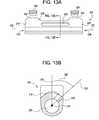
- FIG. 13Ais a side view of an exemplary embodiment of a connector for connecting two spinal rods having a single adjustment opening
- FIG. 13Bis an end view in cross section of the connector of FIG. 13A taken along the lines B-B of FIG. 13A ;
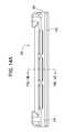
- FIG. 14Ais a side view of another exemplary embodiment of a connector for connecting two spinal rods
- FIG. 14Bis an end view of the connector of FIG. 14A ;
- FIG. 14Cis a side view in cross section of the connector of FIG. 14A taken along the lines F-F of FIG. 14B ;
- FIG. 14Dis a side view in cross section of the connector of FIG. 14A taken along the lines G-G of FIG. 14B ;
- FIG. 14Eis an end view in cross section of the connector of FIG. 14A taken along the lines H-H of FIG. 14A ;
- FIG. 14Fis a perspective view of the connector of FIG. 14A ;
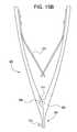
- FIG. 15Ais a right side view of another exemplary embodiment of an adjustment instrument.
- FIG. 15Bis a left side view of the adjustment instrument of FIG. 15 .
- an elementmeans one element or more than one element.
- FIGS. 1-5illustrate an exemplary embodiment of a rod-to-rod connector 10 for connecting a first spinal rod 12 to a second spinal rod 14 in an end-to-end, e.g., tandem, arrangement for permitting subsequent adjustment of one or both of the spinal rods 10 , 14 relative to each other and to the connector 10 .
- the exemplary connectormay comprise a body 16 having a first end 18 and a second end 20 spaced apart from the first end 18 of the connector 10 .
- the first end 18 of the body 16 of the exemplary connector 10may have a first rod opening 22 formed therein for receiving the first spinal rod 12 and the second end 20 of the body 16 may have a second rod opening 24 formed therein for receiving the second rod 14 .
- the body 16 of the connector 10may have a passage extending between the first rod opening 22 and the second rod opening 24 in which a portion of the first rod 12 and a portion of the second rod 14 may be positioned.
- the body 16 of the connector 10is approximately cylindrical in shape and the passage, including the first and second rod openings 22 , 24 , is approximately cylindrical in shape, each having an approximately circular cross section.
- the body 16 and/or the passage within the body 16may have different shapes.
- the body 16 and/or the passage within the body 16 , including the first and second rod openings 22 , 24may have a polygonal, square, elliptical, rectilinear, or other suitable cross sectional shape.
- the passage, including the first and second rod openings 22 , 24has a cross sectional shape approximately corresponding to the cross sectional shape of the spinal rod received thereby.
- the first rod opening 22 , the second rod opening 24 , and the passage therebetweenhave an approximately circular cross section approximately corresponding in size and shape to the first spinal rod 12 and second spinal rod 14 , respectively.
- the first rod opening 22 , the second rod opening 24 , and the passage therebetweenmay be approximately corresponding in size and shape.
- the first rod opening 22 , the second rod opening 24 , and the passage therebetweenare equivalent in size and shape to receive and connect a first spinal rod 12 and a second spinal rod 14 that are equivalent in size and shape.
- the first rod opening 22 , the second rod opening 24 , and portions of the passage therebetweenmay be distinct in size and shape to receive and connect two spinal rods of different size and/or shape, for example, to receive and connect a spinal rod having a square cross section with a cylindrical spinal rod having a circular cross section or to receive and connect a 4.5 mm diameter cylindrical spinal rod to a 5.5 mm diameter cylindrical spinal rod.
- the passage within the bodyextends uninterrupted between the first rod opening 22 and the second rod opening 24 .
- the body 16 of the connector 10may have a first passage opening at the first rod opening and a second passage opening at the second rod opening, wherein the first passage and the second passage are interrupted, i.e., are not connected.
- the body 16 of the connector 10may have a plurality of spaced apart adjustment openings 30 oriented along the length of the body 16 between the first end 18 and the second end 20 of the body 16 of the connector 10 .
- the adjustment openings 30may communicate with the passage within the body 16 , for example, to allow a portion of an adjustment instrument or other instruments to access the passage and one or more rods positioned within the passage.
- the number of adjustment openingsmay vary depending on, for example, the length of the body 16 of the connector 10 and the size of the adjustment openings 30 . For embodiments with a longer length body 16 , preferably, two or more adjustment openings are provided and for embodiments with a shorter length body 16 , one adjustment opening may be provided, as illustrated in FIG. 13 .
- the space between adjacent adjustment openings 30may be constant, as in the illustrated embodiment, or may be distinct.
- a set of adjustment openings 30may be arranged linearly in an orientation parallel to the longitudinal axis 32 of the passage of the body 16 .
- One or more sets of adjustment openingsmay be provided. In the illustrated embodiment, for example, two sets of adjustment openings may be provided—a first set of adjustment openings 30 A-C and a second set of adjustment openings 30 D-F.
- a set of adjustment openingsmay be arranged non-linearly and/or such that a portion of two or more adjustment openings overlap at a segment of the passage.
- the body 16 of the connector 10may have a first closure mechanism receiving opening 40 and a second closure mechanism receiving opening 42 .
- the first closure mechanism receiving opening 40may communicate with the passage receiving the first spinal rod 12 to allow delivery of a closure mechanism for locking the position of the first spinal rod 12 within the passage.
- the second closure mechanism receiving opening 42may communicate with the passage receiving the second spinal rod 14 to allow delivery of a closure mechanism for locking the position of the second spinal rod 14 within the passage.
- the size and shape of the first closure mechanism receiving opening 40 and the second closure mechanism receiving opening 42may be selected to receive any know closure mechanism for locking a spinal rod to a spinal implant such as a bone anchor, a cross connector, or a bone plate.
- Such conventional closure mechanismsinclude, for example, a set screw that may be threaded directly, or indirectly through a compression member, into contact with the spinal rod to lock the rod in a desired position.
- the first closure mechanism receiving opening 40 and the second closure mechanism receiving opening 42are configured to receive a set screw.
- the first closure mechanism receiving opening 40 and the second closure mechanism receiving opening 42include internal threads for threaded engagement with a respective set screw.
- the first closure mechanism receiving opening 40 and the second closure mechanism receiving opening 42may be configured to receive similar closure mechanisms, as in the illustrated exemplary embodiment, or distinct closure mechanisms.
- the first closure mechanism receiving opening 40 and the second closure mechanism receiving opening 42may be positioned anywhere along the length of the body 16 of the connector 10 .
- the first closure mechanism receiving opening 40is positioned proximate the first end 18 of the body 16 of the connector 10 and the second closure mechanism receiving opening 42 is positioned proximate the second end 20 of the body 16 of the connector 10 .
- the first closure mechanism receiving opening 40 and the second closure mechanism receiving opening 42may be oriented to facilitate placement of the closure mechanisms from the top of the connector.
- the first closure mechanism receiving opening 40 and the second closure mechanism receiving opening 42may be oriented in a first plane 50 that intersects the longitudinal axis 32 of the passage and the top surface of the body 16 of the connector 10 , as illustrated in FIG. 11 .
- the adjustment openings 30may be oriented to facilitate access to the passage and the spinal rods therein from the top of the connector.
- the first closure mechanism receiving opening 40 and the second closure mechanism receiving opening 42 and the adjustment openings 30are oriented to facilitate access to the respective openings from the top of the connector preferably without necessitating rotation or other adjustment of the connector 10 .
- a plurality of adjustment openings 30such as the first set of adjustment openings 30 A- 30 C of the exemplary embodiment, may be oriented in a second plane 52 that may intersect the first plane 50 and the adjustment openings 30 .
- the second plane 52may be oriented at a first angle 62 to the first plane 50 .
- the first angle 62may be greater than approximately 0 degrees. In certain exemplary embodiments, the first angle may be greater than or equal to approximately 0 degrees and less than approximately 90 degrees and preferably may be between approximately 20 degrees and approximately 70 degrees.
- a second set of adjustment openings 30may be oriented in a third plane 54 that intersects the first plane 50 and the adjustment openings 30 .
- the third plane 54may be oriented at a second angle 64 to the first plane 50 .
- the second angle 64may be greater than approximately 0 degrees.
- the second angle 64may be greater that approximately 0 degrees and less than approximately 90 degrees and preferably may be between approximately 20 degrees and approximately 70 degrees.
- the first angle 62may be approximately equal to the second angle 64 or may be distinct from the second angle 64 .
- the third plane 54may be oriented at a third angle 66 to the second plane 52 .
- the third angleis preferably greater than approximately 45 degrees and in the illustrated embodiment is approximately 90 degrees.
- the first end 18 and/or the second end 20 of the body 16 of the connector 10can include a sloped surface 60 to facilitate positioning of the connector 10 relative to a spinal rod and to minimize trauma to body tissue during positioning of the connector 10 .
- the first end 18includes a sloped surface 60 a that is sloped at a first slope angle 67 to a line perpendicular to the longitudinal axis 32 of the passage.
- the second end 20includes a sloped surface 60 b that is sloped at a second slope angle 69 to a line perpendicular to the longitudinal axis 32 of the passage.
- the first slope angle 67 and the second slope angle 69may be approximately equal, as in the illustrated embodiment, or may be distinct.
- the first slope angle 67 and the second slope angle 69may be any angle sufficient to minimize tissue trauma.
- the first slope angle 67 and the second slope angle 69may be greater than approximately 0 degrees and less than approximately 90 degrees and, preferably is greater than approximately 15 degrees.
- the connector 10may be constructed from any biocompatible material suitable for implantation in the body. Such materials may include metals and metal alloys, such as stainless steel and titanium, polymers, ceramics, or composites.
- FIGS. 6-8illustrate the connector 10 connecting a first dual diameter rod 80 to a second dual diameter rod 82 .
- the first dual diameter rod 80comprises a first segment 84 having a first diameter and a second segment 86 having a second diameter distinct from the first diameter.
- the first diameteris greater than the second diameter.
- the second diametermay be greater than the first diameter.
- the second dual diameter rod 82comprises a first segment 88 having a first diameter and a second segment 90 having a second diameter distinct from the first diameter.
- the first diameteris greater than the second diameter.
- the second diametermay be greater than the first diameter.
- the connectors disclosed hereinmay be used to connect two rods in an end-to-end, e.g., tandem, arrangement in a bilateral, unilateral or other construct.
- One exemplary method for connecting and adjusting two spinal rodsmay include positioning a first spinal rod 12 within the passage of the connector 10 through a first opening 22 at a first end 18 of the connector 10 and positioning a second spinal rod 12 within the passage of the connector 10 through a second opening 24 at a second end 20 of the connector 10 .
- the rodsmay be positioned within the connector before or after the rods are implanted proximate the spine.
- first opening 22may be positioned about an end of the first spinal rod 12 and the connector 10 may be advanced along the first spinal rod 12 and the second opening 24 may be positioned about the second spinal rod 14 and the connector 10 may be advanced along the second spinal rod 14 until the first spinal rod 12 and the second spinal rod 14 are in the desired position within the passage of the connector 10 .
- An adjustment instrumentmay be used to adjust the position of the first spinal rod (e.g., 12 , 80 ) and/or the second spinal rod (e.g., 14 , 82 ) within the passage of the connector 10 .
- a distal end 100 of an adjustment instrumentmay be inserted into a first adjustment opening 30 , for example, adjustment opening 30 B, in the connector 10 to adjust the position of the first spinal rod 12 and/or the second spinal rod 14 .
- the distal end 100 of the adjustment instrumentmay be inserted into a second adjustment opening in the connector, spaced from the first adjustment opening, for example, adjustment opening 30 A and/or 30 C, to adjust the position of the first spinal rod 12 and/or the second spinal rod 14 .
- first spinal rod 12 and/or the second spinal rod 14 within the passage of the connector 10may be secured by operation of the closure mechanisms positioned within the first closure mechanism opening 40 and the second closure mechanism opening 42 .
- a distal end of the adjustment instrumentmay be inserted through one or more adjustment openings 30 to contact and adjust the first spinal rod 12 and/or the second spinal rod 14 .
- a first component 102 of the distal end 100 of the adjustment instrumentmay be positioned through an adjustment opening 30 and against the second spinal rod 14 .
- a second component 104 of the distal end 100 of the adjustment instrumentmay be positioned through the same or separate adjustment opening 30 as the first component 102 and against the first spinal rod 12 . Separation of the first component 102 and the second component 104 may adjust the first spinal rod 12 and/or the second spinal rod 14 relative to one another.
- a distal end of the adjustment instrumentmay be inserted through one or more adjustment opening 30 to contact a portion of the connector 10 and a spinal rod to facilitate adjustment the first spinal rod 12 and the second spinal rod 14 .
- a first component 102 of the distal end 100 of the adjustment instrumentmay be positioned through an adjustment opening 30 and against an edge 34 of an adjustment opening 30 .
- a second component 104 of the distal end 100 of the adjustment instrumentmay be positioned through the same or separate adjustment opening 30 as the first component 102 and against the first spinal rod 12 . Separation of the first component 102 and the second component 104 may adjust the first spinal rod 12 relative to the connector 10 and the second spinal rod 14 .
- one or both of the components of the adjustment instrumentmay include a foot or like structure extending in a direction parallel to the longitudinal axis 32 of the passage of the connector when the distal end of the adjustment instrument in positioned through an adjustment opening.
- the distal end 110 of an adjustment instrumentmay include a first component 112 having a first foot 116 oriented approximately perpendicular to the first component 112 and a second component 114 having a second foot 118 oriented approximately perpendicular to the second component 114 .
- the first foot 116 and the second foot 118may be oriented parallel to each other and parallel to the longitudinal axis 32 of the passage of the connector 10 when the first foot 116 and the second foot 118 are positioned within the passage.
- the length L of the first foot 116 and the second foot 118may be selected to be greater than or equal to the space between adjacent adjustment openings 30 of the connector 10 .
- the first foot 116 and the second foot 118may have the same or different lengths.
- the connector 10may be accessed by making an incision in the patient and creating a path through the patient's tissue to proximate the connector 10 .
- the connector 10is accessed through minimally invasive surgical techniques to minimize trauma to surrounding tissue. For example, a small, puncture incision may be made and dilated by one or more dilators to create a pathway to the connector 10 .
- a port, retractor, or other access devicemay be utilized to create and maintain the pathway to the connector 10 .
- the first spinal rod 12 and/or the second spinal rod 14may be released to permit adjustment of one or both of the spinal rods within the passage of the connector.
- the spinal rodsmay be released by operation of a respective closure mechanism.
- the released spinal rod or rodsthen may be adjusted in any manner described above or by other methods, such as by adjusting the position of one or both rods by engaging a portion the rod external to the connector passage with an instrument, such as a rod clamp or a rod holder, and moving the instrument to thereby adjust the position of the rod relative to the connector.
- the adjusted spinal rod(s)may be secured to the connector 10 by operation of a respective closure mechanism.
- FIGS. 13A-Billustrate another exemplary embodiment of a rod-to-rod connector 200 for connecting a first spinal rod to a second rod in an end-to-end, e.g., tandem, arrangement for permitting subsequent adjustment of one or both of the spinal rods relative to each other and to the connector.
- the illustrated exemplary connector 200may be similar in construction and use to the exemplary connector 10 discussed in detail above.
- the exemplary connector 200may comprise a body 216 having a first end 218 and a second end 220 spaced apart from the first end 218 of the connector 210 .
- the first end 218 of the body 216 of the exemplary connector 200may have a first rod opening 222 formed therein for receiving the first spinal rod and the second end 220 of the body 216 may have a second rod opening 224 formed therein for receiving the second rod.
- the body 216 of the connector 200may have a passage 225 extending between the first rod opening 222 and the second rod opening 224 in which a portion of the first rod and a portion of the second rod may be positioned.
- the body 216 of the connector 200may have a first closure mechanism receiving opening 240 and a second closure mechanism receiving opening 242 .
- the first closure mechanism receiving opening 240may communicate with the passage 225 receiving the first spinal rod to allow delivery of a closure mechanism, for example set screw 292 , for locking the position of the first spinal rod within the passage 225 .
- the second closure mechanism receiving opening 242may communicate with the passage 225 receiving the second spinal rod to allow delivery of a closure mechanism, for example set screw 294 , for locking the position of the second spinal rod within the passage 225 .
- the first closure mechanism receiving opening 240 and the second closure mechanism receiving opening 242may be oriented to facilitate placement of the closure mechanisms from the top of the connector.
- first closure mechanism receiving opening 240 and the second closure mechanism receiving opening 242may be oriented in a first plane 250 that intersects the longitudinal axis 232 of the passage and the top surface of the body 216 of the connector 200 , as illustrated in FIG. 13B .
- the exemplary connector 200includes a single adjustment opening 230 oriented along the length of the body 216 of the connector 200 between the first end 218 and the second end 220 of the body 216 of the connector 200 .
- the single adjustment opening 230may communicate with the passage 225 within the body 216 in which a portion of the first rod and the second rod may be positioned to allow a portion of an adjustment instrument or other instruments to access the passage 225 and one or more rods within the passage 225 .
- the adjustment opening 230may be oriented to facilitate access to the passage 225 and the spinal rods therein from the top of the connector.
- the first closure mechanism receiving opening 240 and the second closure mechanism receiving opening 242 and the adjustment opening 230are oriented to facilitate access to the respective openings from the top of the connector preferably without necessitating rotation or other adjustment of the connector 200 .
- the opening 230may be oriented in a second plane 252 that intersects the first plane 250 and the adjustment opening 230 .
- the second plane 252may intersect the first plane 250 proximate the longitudinal axis 232 of the passage 225 .
- the second plane 252may be oriented at a first angle 262 to the first plane 250 .
- the first angle 262may be greater than approximately 0 degrees. In certain exemplary embodiments, the first angle 262 may be greater than approximately 0 degrees and less than or equal to approximately 90 degrees and preferably may be between approximately 20 degrees and approximately 70 degrees.
- FIGS. 14A-14Fillustrate another exemplary embodiment of a rod-to-rod connector 300 for connecting a first spinal rod to a second rod in an end-to-end, e.g., tandem, arrangement for permitting subsequent adjustment of one or both of the spinal rods relative to each other and to the connector.
- the illustrated exemplary connector 300may be similar in construction and use to the exemplary connector 10 discussed in detail above.
- the exemplary connector 300may comprise a body 316 having a first end 318 and a second end 320 spaced apart from the first end 318 of the connector 310 .
- the first end 318 of the body 316 of the exemplary connector 300may have a first rod opening 322 formed therein for receiving the first spinal rod and the second end 320 of the body 316 may have a second rod opening 324 formed therein for receiving the second rod.
- the body 316 of the connector 300may have a passage 325 extending between the first rod opening 322 and the second rod opening 324 in which a portion of the first rod and a portion of the second rod may be positioned.
- the body 316 of the connector 300may have a first closure mechanism receiving opening 340 and a second closure mechanism receiving opening 342 .
- the first closure mechanism receiving opening 340may communicate with the passage 325 receiving the first spinal rod to allow delivery of a closure mechanism, for example set screw 292 , for locking the position of the first spinal rod within the passage 325 .
- the second closure mechanism receiving opening 342may communicate with the passage 325 receiving the second spinal rod to allow delivery of a closure mechanism, for example set screw 294 for locking the position of the second spinal rod within the passage 325 .
- the first closure mechanism receiving opening 340 and the second closure mechanism receiving opening 342may be oriented to facilitate placement of the closure mechanisms from the top of the connector.
- first closure mechanism receiving opening 340 and the second closure mechanism receiving opening 342may be oriented in a first plane 350 that intersects the longitudinal axis 332 of the passage and the top surface of the body 316 of the connector 300 , as illustrated in FIG. 14E .
- the illustrated exemplary connector 300includes two sets of adjustment openings—a first set of spaced-apart adjustment openings 330 A-C and a second set of spaced-apart adjustment openings 330 D-F.
- the adjustment openings 330 A-Fare oriented along the length of the body 316 of the connector 300 between the first end 318 and the second end 320 of the body 316 of the connector 300 .
- the adjustment openings 330 A-Fcommunicate with the passage 325 within the body 316 in which a portion of the first rod and the second rod may be positioned to allow a portion of an adjustment instrument or other instruments to access the passage 325 and one or more rods within the passage 325 .
- the second set of adjustment openings 330 D-Fmay be oriented to facilitate access to the passage 325 and the spinal rods therein from the top of the connector.
- the first closure mechanism receiving opening 340 and the second closure mechanism receiving opening 342 and the second set of adjustment openings 330 D-Fare oriented to facilitate access to the respective openings from the top of the connector preferably without necessitating rotation or other adjustment of the connector 300 .
- the second set of adjustment openings 330 D-Fmay be oriented in a second plane 352 that intersects the first plane 352 and the adjustment opening 330 .
- the second plane 352may intersect the first plane 350 proximate the longitudinal axis 332 of the passage 325 .
- the second plane 352may be oriented at a first angle 362 to the first plane 350 .
- the first angle 362may be greater than approximately 0 degrees. In certain exemplary embodiments, the first angle 362 may be greater that approximately 0 degrees and less than or equal to approximately 90 degrees and preferably may be between approximately 20 degrees and approximately 70 degrees.
- the profile of a rod-to-rod connector within the bodymay be reduced by rotating the connector about the axis of the connector to a reduced profile orientation.
- rotation of the connector 300approximately ninety degrees (90°) from the orientation illustrated in FIG. 14E orients the connector 300 in a reduced profile orientation.
- the first set of adjustment openings 330 A-Cmay be oriented in a third plane 354 that intersects the first plane 350 and the adjustment openings 330 A-C to facilitate access to the respective openings from the top of the connector 300 when the connector is in a reduced profile orientation.
- the third plane 354may intersect the first plane 350 proximate the longitudinal axis 332 of the passage 325 .
- the third plane 354may be oriented at a second angle 364 to the first plane 350 that is selected to permit access to the openings when the connector is oriented in a reduced profile orientation.
- the second angle 364is approximately 90 degrees. Rotation of a connector to a reduced profile orientation may necessitate the use of an angled driver instrument to insert or remove the first and second set screws 290 and 292 .
- the passage of a rod-to-rod connector disclosed hereinmay be configured to facilitate seating and fixing a spinal rod to the connector.
- the passage 325 of the connector 300 proximate the first rod opening 322 and the second rod opening 324may include a recess 370 to create spaced-apart, along the longitudinal axis of the passage 325 , spinal rod contact surfaces 372 and 374 .
- the recess 370is preferably positioned within the passage 325 approximately opposite the closure mechanism, e.g., the set screw 292 and/or 294 , such that tightening of the closure mechanism against the spinal rod causes the rod to deform by bending into the recess 370 . In this manner, increased resistance to motion, e.g., axial slip, of the spinal rod relative to the connector may be achieved.
- one or both of the rod openings of the connectormay be configured to create an interference fit between the rod and the connector upon tightening of the closure mechanism against the rod.
- the first rod opening 322 and/or the second rod opening 324 and/or a portion of the length of the passage 325may be formed from two non-concentric arcuate sections: a upper arcuate section 383 and a lower arcuate section 385 .
- the radius of the upper arcuate section 383may be greater than the radius of the spinal rod to facilitate placement of the spinal rod within the connector.
- the radius of the lower arcuate section 385may be less than or equal to the radius of the spinal rod and less than or equal to the radius of the upper arcuate section 383 .
- the radius of the lower arcuate section 385may be approximately 0.05 mm less than the radius of the spinal rod. Tightening of the closure mechanism against the spinal rod cause the spinal rod to engage the lower arcuate section in an interference fit inhibiting motion of the spinal rod relative to the connector. The resultant force on the spinal rod, and the closure mechanism when tightened against the spinal rod, caused by interference fit may reduce back-out of closure mechanism.
- FIGS. 15A-Billustrates another exemplary embodiment of an adjustment instrument 200 having a first arm 202 pivotally connected to a second arm 204 .
- the distal end 206 of the second arm 204 of the adjustment instrument 200may include a first foot 215 oriented approximately perpendicular to the distal end 206 of the second arm 204 .
- the first foot 215may be oriented generally parallel to the longitudinal axis of the passage of a connector, such as the exemplary connector 10 , when the first foot 215 is positioned in the passage.
- the length of the first foot 215may be selected to be greater than or equal to the space between adjacent openings 30 of the connector.
- FIG. 10the exemplary connector
- the distal end 208 of the first arm 202may lack a foot and, thus, the instrument 200 may have only a single foot, first foot 215 .
- manipulation of the proximal ends of the first arm 202 and second arm 204 togethercauses the distal ends 206 , 208 to pivot about pivot pin 212 and separate from one another to provide for distraction of one or more rods positioned within the passage of a connector.
- the instrument 200may include a spring 210 or the like to bias the distal ends 206 , 208 towards one another.
Landscapes
- Health & Medical Sciences (AREA)
- Orthopedic Medicine & Surgery (AREA)
- Neurology (AREA)
- Life Sciences & Earth Sciences (AREA)
- Surgery (AREA)
- Heart & Thoracic Surgery (AREA)
- Engineering & Computer Science (AREA)
- Biomedical Technology (AREA)
- Nuclear Medicine, Radiotherapy & Molecular Imaging (AREA)
- Medical Informatics (AREA)
- Molecular Biology (AREA)
- Animal Behavior & Ethology (AREA)
- General Health & Medical Sciences (AREA)
- Public Health (AREA)
- Veterinary Medicine (AREA)
- Surgical Instruments (AREA)
- Prostheses (AREA)
Abstract
Description
Claims (14)
Priority Applications (1)
| Application Number | Priority Date | Filing Date | Title |
|---|---|---|---|
| US11/776,909US8475499B2 (en) | 2006-07-14 | 2007-07-12 | Rod to rod connectors and methods of adjusting the length of a spinal rod construct |
Applications Claiming Priority (2)
| Application Number | Priority Date | Filing Date | Title |
|---|---|---|---|
| US80737706P | 2006-07-14 | 2006-07-14 | |
| US11/776,909US8475499B2 (en) | 2006-07-14 | 2007-07-12 | Rod to rod connectors and methods of adjusting the length of a spinal rod construct |
Publications (2)
| Publication Number | Publication Date |
|---|---|
| US20080027436A1 US20080027436A1 (en) | 2008-01-31 |
| US8475499B2true US8475499B2 (en) | 2013-07-02 |
Family
ID=38987302
Family Applications (1)
| Application Number | Title | Priority Date | Filing Date |
|---|---|---|---|
| US11/776,909Active2030-01-18US8475499B2 (en) | 2006-07-14 | 2007-07-12 | Rod to rod connectors and methods of adjusting the length of a spinal rod construct |
Country Status (1)
| Country | Link |
|---|---|
| US (1) | US8475499B2 (en) |
Cited By (42)
| Publication number | Priority date | Publication date | Assignee | Title |
|---|---|---|---|---|
| US20110054536A1 (en)* | 2008-11-11 | 2011-03-03 | Kspine, Inc. | Growth directed vertebral fixation system with distractible connector(s) and apical control |
| US8920472B2 (en) | 2011-11-16 | 2014-12-30 | Kspine, Inc. | Spinal correction and secondary stabilization |
| US9011491B2 (en) | 2004-08-03 | 2015-04-21 | K Spine, Inc. | Facet device and method |
| US9168071B2 (en) | 2009-09-15 | 2015-10-27 | K2M, Inc. | Growth modulation system |
| US9168070B2 (en) | 2012-09-07 | 2015-10-27 | K2M, Inc. | Growing spinal rod system |
| US9173681B2 (en) | 2009-03-26 | 2015-11-03 | K2M, Inc. | Alignment system with longitudinal support features |
| US9333009B2 (en) | 2011-06-03 | 2016-05-10 | K2M, Inc. | Spinal correction system actuators |
| US9339306B2 (en) | 2012-08-29 | 2016-05-17 | K2M, Inc. | Adjustable axial spinal rod connector |
| USD758169S1 (en)* | 2015-02-25 | 2016-06-07 | Aluvision, N.V. | Frame connector |
| US9468468B2 (en) | 2011-11-16 | 2016-10-18 | K2M, Inc. | Transverse connector for spinal stabilization system |
| US9468469B2 (en) | 2011-11-16 | 2016-10-18 | K2M, Inc. | Transverse coupler adjuster spinal correction systems and methods |
| US9468471B2 (en) | 2013-09-17 | 2016-10-18 | K2M, Inc. | Transverse coupler adjuster spinal correction systems and methods |
| US9763703B2 (en) | 2015-05-05 | 2017-09-19 | Degen Medical, Inc. | Cross connectors, kits, and methods |
| US9931138B2 (en)* | 2014-10-15 | 2018-04-03 | Globus Medical, Inc. | Orthopedic extendable rods |
| US9931140B2 (en) | 2012-08-30 | 2018-04-03 | K2M, Inc. | Multi-planar axial spinal rod connector |
| US20180125533A1 (en)* | 2015-04-17 | 2018-05-10 | Apifix Ltd. | Expandable polyaxial spinal system |
| US10016220B2 (en) | 2011-11-01 | 2018-07-10 | Nuvasive Specialized Orthopedics, Inc. | Adjustable magnetic devices and methods of using same |
| US10039661B2 (en) | 2006-10-20 | 2018-08-07 | Nuvasive Specialized Orthopedics, Inc. | Adjustable implant and method of use |
| US10092328B2 (en) | 2015-01-13 | 2018-10-09 | Stryker European Holdings I, Llc | Growing rods and methods of use |
| US10238427B2 (en) | 2015-02-19 | 2019-03-26 | Nuvasive Specialized Orthopedics, Inc. | Systems and methods for vertebral adjustment |
| US10271885B2 (en) | 2014-12-26 | 2019-04-30 | Nuvasive Specialized Orthopedics, Inc. | Systems and methods for distraction |
| US10342581B2 (en) | 2011-11-16 | 2019-07-09 | K2M, Inc. | System and method for spinal correction |
| US10349995B2 (en) | 2007-10-30 | 2019-07-16 | Nuvasive Specialized Orthopedics, Inc. | Skeletal manipulation method |
| US10405891B2 (en) | 2010-08-09 | 2019-09-10 | Nuvasive Specialized Orthopedics, Inc. | Maintenance feature in magnetic implant |
| US10478232B2 (en) | 2009-04-29 | 2019-11-19 | Nuvasive Specialized Orthopedics, Inc. | Interspinous process device and method |
| US10517643B2 (en) | 2009-02-23 | 2019-12-31 | Nuvasive Specialized Orthopedics, Inc. | Non-invasive adjustable distraction system |
| US10617453B2 (en) | 2015-10-16 | 2020-04-14 | Nuvasive Specialized Orthopedics, Inc. | Adjustable devices for treating arthritis of the knee |
| US10646262B2 (en) | 2011-02-14 | 2020-05-12 | Nuvasive Specialized Orthopedics, Inc. | System and method for altering rotational alignment of bone sections |
| US10660675B2 (en) | 2010-06-30 | 2020-05-26 | Nuvasive Specialized Orthopedics, Inc. | External adjustment device for distraction device |
| US10702311B2 (en) | 2011-11-16 | 2020-07-07 | K2M, Inc. | Spinal correction and secondary stabilization |
| US10729470B2 (en) | 2008-11-10 | 2020-08-04 | Nuvasive Specialized Orthopedics, Inc. | External adjustment device for distraction device |
| US10743794B2 (en) | 2011-10-04 | 2020-08-18 | Nuvasive Specialized Orthopedics, Inc. | Devices and methods for non-invasive implant length sensing |
| US10751094B2 (en) | 2013-10-10 | 2020-08-25 | Nuvasive Specialized Orthopedics, Inc. | Adjustable spinal implant |
| US10835290B2 (en) | 2015-12-10 | 2020-11-17 | Nuvasive Specialized Orthopedics, Inc. | External adjustment device for distraction device |
| US10918425B2 (en) | 2016-01-28 | 2021-02-16 | Nuvasive Specialized Orthopedics, Inc. | System and methods for bone transport |
| US11191579B2 (en) | 2012-10-29 | 2021-12-07 | Nuvasive Specialized Orthopedics, Inc. | Adjustable devices for treating arthritis of the knee |
| US11202707B2 (en) | 2008-03-25 | 2021-12-21 | Nuvasive Specialized Orthopedics, Inc. | Adjustable implant system |
| US11246694B2 (en) | 2014-04-28 | 2022-02-15 | Nuvasive Specialized Orthopedics, Inc. | System for informational magnetic feedback in adjustable implants |
| US11357549B2 (en) | 2004-07-02 | 2022-06-14 | Nuvasive Specialized Orthopedics, Inc. | Expandable rod system to treat scoliosis and method of using the same |
| US11446064B2 (en) | 2018-04-26 | 2022-09-20 | Stryker European Operations Holdings Llc | Orthopedic growing devices |
| US11547450B2 (en) | 2015-04-17 | 2023-01-10 | Apifix Ltd. | Expandable polyaxial spinal system |
| USD1077629S1 (en)* | 2024-06-21 | 2025-06-03 | Yiwu Qiufa Toys Co., Ltd | Fastener |
Families Citing this family (54)
| Publication number | Priority date | Publication date | Assignee | Title |
|---|---|---|---|---|
| GB0521585D0 (en)* | 2005-10-22 | 2005-11-30 | Depuy Int Ltd | A spinal support rod |
| GB0521582D0 (en)* | 2005-10-22 | 2005-11-30 | Depuy Int Ltd | An implant for supporting a spinal column |
| GB0600662D0 (en)* | 2006-01-13 | 2006-02-22 | Depuy Int Ltd | Spinal support rod kit |
| US8348952B2 (en) | 2006-01-26 | 2013-01-08 | Depuy International Ltd. | System and method for cooling a spinal correction device comprising a shape memory material for corrective spinal surgery |
| WO2008128105A1 (en)* | 2007-04-12 | 2008-10-23 | Texas Scottish Rite Hospital For Children | Orthopedic fastener for stabilization and fixation |
| US20090105756A1 (en) | 2007-10-23 | 2009-04-23 | Marc Richelsoph | Spinal implant |
| GB0720762D0 (en)* | 2007-10-24 | 2007-12-05 | Depuy Spine Sorl | Assembly for orthopaedic surgery |
| US9345517B2 (en) | 2008-02-02 | 2016-05-24 | Globus Medical, Inc. | Pedicle screw having a removable rod coupling |
| WO2009097623A2 (en)* | 2008-02-02 | 2009-08-06 | Texas Scottish Rite Hospital For Children | Pedicle screw |
| US9408641B2 (en)* | 2008-02-02 | 2016-08-09 | Globus Medical, Inc. | Spinal rod link reducer |
| US9579126B2 (en)* | 2008-02-02 | 2017-02-28 | Globus Medical, Inc. | Spinal rod link reducer |
| JP2009207877A (en)* | 2008-02-07 | 2009-09-17 | Showa Ika Kohgyo Co Ltd | Rod connector |
| JP2011511676A (en)* | 2008-02-07 | 2011-04-14 | ケー2エム, インコーポレイテッド | Automatic expansion bone fixation device |
| US9060813B1 (en) | 2008-02-29 | 2015-06-23 | Nuvasive, Inc. | Surgical fixation system and related methods |
| US20090240284A1 (en)* | 2008-03-24 | 2009-09-24 | David Scott Randol | Stabilization rods |
| US20100049252A1 (en)* | 2008-08-21 | 2010-02-25 | Southern Spine, Llc | Transverse Connector Device for Extending an Existing Spinal Fixation System |
| US9603629B2 (en)* | 2008-09-09 | 2017-03-28 | Intelligent Implant Systems Llc | Polyaxial screw assembly |
| US11241257B2 (en) | 2008-10-13 | 2022-02-08 | Nuvasive Specialized Orthopedics, Inc. | Spinal distraction system |
| US20100094303A1 (en)* | 2008-10-13 | 2010-04-15 | Arvin Chang | Spinal distraction system |
| US20100114167A1 (en)* | 2008-10-31 | 2010-05-06 | Warsaw Orthopedic, Inc. | Transition rod |
| EP2352449B1 (en) | 2008-11-03 | 2018-02-21 | Synthes GmbH | Adjustable rod assembly |
| GB2465156B (en)* | 2008-11-05 | 2012-09-26 | Dalmatic Lystrup As | Bone fixation system |
| US8162984B2 (en) | 2009-02-20 | 2012-04-24 | K2M, Inc. | Forced growth axial growing spine device |
| WO2010096829A2 (en)* | 2009-02-23 | 2010-08-26 | Crocker Spinal, L.L.C. | Press-on link for surgical screws |
| US9095380B2 (en)* | 2009-03-31 | 2015-08-04 | Hamid R. Mir | Spinous process cross-link |
| US20100292736A1 (en)* | 2009-05-15 | 2010-11-18 | Warsaw Orthopedic, Inc. | Linkage for Connection of Fusion and Non-Fusion Systems |
| KR100935233B1 (en)* | 2009-06-08 | 2010-01-06 | 주식회사 지에스메디칼 | Length-adjustable rod for spinal fixation |
| JP5751642B2 (en) | 2009-09-04 | 2015-07-22 | エリプス テクノロジーズ, インク.Ellipse Technologies, Inc. | Bone growth apparatus and method |
| US20110172720A1 (en)* | 2010-01-13 | 2011-07-14 | Kyphon Sarl | Articulating interspinous process clamp |
| EP2460482A1 (en)* | 2010-12-03 | 2012-06-06 | Zimmer Spine | Rod holding device |
| US9387013B1 (en) | 2011-03-01 | 2016-07-12 | Nuvasive, Inc. | Posterior cervical fixation system |
| US10016226B2 (en) | 2011-12-12 | 2018-07-10 | Children's Hospital Medical Center Of Akron | Noninvasive device for adjusting fastener |
| US9949761B2 (en)* | 2011-12-12 | 2018-04-24 | Children's Hospital Medical Center Of Akron | Noninvasive device for adjusting fastener |
| US20130338714A1 (en) | 2012-06-15 | 2013-12-19 | Arvin Chang | Magnetic implants with improved anatomical compatibility |
| US9044281B2 (en) | 2012-10-18 | 2015-06-02 | Ellipse Technologies, Inc. | Intramedullary implants for replacing lost bone |
| US9179938B2 (en) | 2013-03-08 | 2015-11-10 | Ellipse Technologies, Inc. | Distraction devices and method of assembling the same |
| US10226242B2 (en) | 2013-07-31 | 2019-03-12 | Nuvasive Specialized Orthopedics, Inc. | Noninvasively adjustable suture anchors |
| US9801734B1 (en) | 2013-08-09 | 2017-10-31 | Nuvasive, Inc. | Lordotic expandable interbody implant |
| US9044273B2 (en) | 2013-10-07 | 2015-06-02 | Intelligent Implant Systems, Llc | Polyaxial plate rod system and surgical procedure |
| US10438511B2 (en) | 2013-11-11 | 2019-10-08 | K2M, Inc. | Growing spine model |
| US10198970B2 (en)* | 2014-07-14 | 2019-02-05 | K2M, Inc. | Growing spine model |
| KR102588501B1 (en) | 2014-10-23 | 2023-10-11 | 누베이시브 스페셜라이즈드 오소페딕스, 인크. | Remotely adjustable interactive bone reshaping implant |
| US9980757B2 (en)* | 2014-12-01 | 2018-05-29 | Ebi, Llc | Anchor and rod connector |
| WO2017139548A1 (en) | 2016-02-10 | 2017-08-17 | Nuvasive Specialized Orthopedics, Inc. | Systems and methods for controlling multiple surgical variables |
| US10835384B2 (en)* | 2016-09-13 | 2020-11-17 | Mayo Foundation For Medical Education And Research | Facet joint replacement devices |
| WO2018102101A2 (en) | 2016-11-09 | 2018-06-07 | Children's Hospital Medical Center Of Akron | Distraction osteogenesis system |
| US11737793B2 (en) | 2017-10-20 | 2023-08-29 | Mayo Foundation For Medical Education And Research | Facet joint replacement devices |
| JP2022519380A (en) | 2019-02-07 | 2022-03-23 | ニューベイシブ スペシャライズド オーソペディックス,インコーポレイテッド | Ultrasonic communication in medical devices |
| US11589901B2 (en) | 2019-02-08 | 2023-02-28 | Nuvasive Specialized Orthopedics, Inc. | External adjustment device |
| WO2021144636A1 (en)* | 2020-01-19 | 2021-07-22 | Inno4Spine Ag | Connector implant for extending a spinal construct |
| US12213708B2 (en) | 2020-09-08 | 2025-02-04 | Nuvasive Specialized Orthopedics, Inc. | Remote control module for adjustable implants |
| US20220265326A1 (en) | 2021-02-23 | 2022-08-25 | Nuvasive Specialized Orthopedics, Inc. | Adjustable implant, system and methods |
| US11737787B1 (en) | 2021-05-27 | 2023-08-29 | Nuvasive, Inc. | Bone elongating devices and methods of use |
| EP4380480A1 (en) | 2021-08-03 | 2024-06-12 | NuVasive Specialized Orthopedics, Inc. | Adjustable implant |
Citations (58)
| Publication number | Priority date | Publication date | Assignee | Title |
|---|---|---|---|---|
| US270478A (en) | 1883-01-09 | Coupling for wires and electric conductors | ||
| US721411A (en) | 1902-04-07 | 1903-02-24 | Clinton Brown Alexander | Device for repairing metallic measuring-tapes. |
| US1647802A (en) | 1925-05-23 | 1927-11-01 | Edward E Josef | Shaft coupling |
| US2278320A (en)* | 1941-05-10 | 1942-03-31 | Hilbert K Kath | Locking turnbuckle |
| US2333033A (en) | 1943-06-11 | 1943-10-26 | Leslie E Mraz | Bone splint |
| US2360019A (en)* | 1942-03-05 | 1944-10-10 | Ryan | Turnbuckle and wrench therefor |
| US3900025A (en) | 1974-04-24 | 1975-08-19 | Jr Walter P Barnes | Apparatus for distracting or compressing longitudinal bone segments |
| US4034746A (en) | 1975-08-01 | 1977-07-12 | Williams Robert W | Retractor |
| US4386603A (en) | 1981-03-23 | 1983-06-07 | Mayfield Jack K | Distraction device for spinal distraction systems |
| US4611582A (en)* | 1983-12-27 | 1986-09-16 | Wisconsin Alumni Research Foundation | Vertebral clamp |
| US4658809A (en)* | 1983-02-25 | 1987-04-21 | Firma Heinrich C. Ulrich | Implantable spinal distraction splint |
| US4747394A (en) | 1986-10-08 | 1988-05-31 | Watanabe Orthopedic Systems, Inc. | Spinal retractor |
| US4780018A (en)* | 1986-03-13 | 1988-10-25 | Godden Braden C | Framework connector |
| US4827918A (en) | 1985-08-15 | 1989-05-09 | Sven Olerud | Fixing instrument for use in spinal surgery |
| US4887596A (en)* | 1988-03-02 | 1989-12-19 | Synthes (U.S.A.) | Open backed pedicle screw |
| US4926849A (en) | 1986-12-19 | 1990-05-22 | Downey Ernest L | Apparatus for separating vertebrae |
| US4929247A (en) | 1988-10-06 | 1990-05-29 | Rayhack John M | Bone compression and distraction device |
| US4931055A (en) | 1986-05-30 | 1990-06-05 | John Bumpus | Distraction rods |
| US5088245A (en)* | 1990-08-07 | 1992-02-18 | W. H. Porter, Inc. | Interconnected hexagonal building structures |
| US5116334A (en)* | 1988-12-21 | 1992-05-26 | Zimmer, Inc. | Posterior spinal system and method |
| US5129903A (en) | 1988-06-18 | 1992-07-14 | Luhr Hans Georg | Bone plate |
| US5133716A (en) | 1990-11-07 | 1992-07-28 | Codespi Corporation | Device for correction of spinal deformities |
| US5154718A (en)* | 1988-12-21 | 1992-10-13 | Zimmer, Inc. | Spinal coupler assembly |
| US5167662A (en) | 1992-01-24 | 1992-12-01 | Zimmer, Inc. | Temporary clamp and inserter for a posterior midline spinal clamp |
| US5290288A (en) | 1990-02-08 | 1994-03-01 | Vignaud Jean Louis | Multi-function device for the osteosynthesis of rachis |
| US5468241A (en) | 1988-02-18 | 1995-11-21 | Howmedica Gmbh | Support device for the human vertebral column |
| US5474207A (en)* | 1994-07-01 | 1995-12-12 | Fiber Technology Corporation | Liquid storage tank with glass reinforced plastic tie rods |
| US5540696A (en) | 1995-01-06 | 1996-07-30 | Zimmer, Inc. | Instrumentation for use in orthopaedic surgery |
| US5571192A (en)* | 1994-07-02 | 1996-11-05 | Heinrich Ulrich | Prosthetic vertebral implant |
| US5643260A (en)* | 1995-02-14 | 1997-07-01 | Smith & Nephew, Inc. | Orthopedic fixation system |
| US5658284A (en)* | 1994-06-30 | 1997-08-19 | Allo Pro Ag | Connection member for the connection of a resilient rod with a bone screw which can be anchored in a vertebra |
| US5700263A (en) | 1996-06-17 | 1997-12-23 | Schendel; Stephen A. | Bone distraction apparatus |
| US5765957A (en)* | 1996-12-16 | 1998-06-16 | The Boeing Company | Lockable turnbuckle assembly |
| US5885283A (en) | 1992-08-04 | 1999-03-23 | Gittleman; Neal B. | Osteogenic mandibular distention apparatus and method |
| US5899903A (en) | 1994-03-18 | 1999-05-04 | Sofamor, S.N.C. | Fixing device for a rigid transverse connection device between rods of a spinal osteosynthesis system |
| US5914137A (en)* | 1992-05-13 | 1999-06-22 | Rascor Spezialbau Gmbh | Apparatus for injecting grout into a spreader pipe used in the erection of concrete walls |
| US6113600A (en) | 1995-06-06 | 2000-09-05 | Denek Medical, Inc. | Device for linking adjacent rods in spinal instrumentation |
| US6126660A (en) | 1998-07-29 | 2000-10-03 | Sofamor Danek Holdings, Inc. | Spinal compression and distraction devices and surgical methods |
| US6332887B1 (en) | 1999-04-06 | 2001-12-25 | Benjamin D. Knox | Spinal fusion instrumentation system |
| US20020055782A1 (en)* | 1998-10-27 | 2002-05-09 | Bagby George W. | 10012255g spinal fusion device, bone joining implant, and vertebral fusion implant |
| US6432108B1 (en) | 2000-01-24 | 2002-08-13 | Depuy Orthopaedics, Inc. | Transverse connector |
| US6447545B1 (en)* | 2000-07-01 | 2002-09-10 | George W. Bagby | Self-aligning bone implant |
| US6451019B1 (en) | 1998-10-20 | 2002-09-17 | St. Francis Medical Technologies, Inc. | Supplemental spine fixation device and method |
| US20030167059A1 (en) | 2002-03-04 | 2003-09-04 | Young John Stewart | Devices and methods for spinal compression and distraction |
| US6645206B1 (en)* | 1995-03-27 | 2003-11-11 | Sdgi Holdings, Inc. | Interbody fusion device and method for restoration of normal spinal anatomy |
| US6648891B2 (en) | 2001-09-14 | 2003-11-18 | The Regents Of The University Of California | System and method for fusing spinal vertebrae |
| US6663631B2 (en)* | 2000-12-01 | 2003-12-16 | Charles A. Kuntz | Method and device to correct instability of hinge joints |
| US20040069517A1 (en)* | 2002-10-09 | 2004-04-15 | Olson Mark H. | Set screw type raintight threadless couplings & conncectors for electrical conduits |
| US6899734B2 (en)* | 2001-03-23 | 2005-05-31 | Howmedica Osteonics Corp. | Modular implant for fusing adjacent bone structure |
| US20050277926A1 (en) | 2004-06-15 | 2005-12-15 | Farris Robert A | Spinal rod system |
| US7029472B1 (en)* | 1999-06-01 | 2006-04-18 | Fortin Frederic | Distraction device for the bones of children |
| US7066938B2 (en) | 2002-09-09 | 2006-06-27 | Depuy Spine, Inc. | Snap-on spinal rod connector |
| US7214226B2 (en) | 2002-07-24 | 2007-05-08 | Nas Spine, Inc. | Compressible fixation apparatus for spinal surgery |
| US20070191841A1 (en)* | 2006-01-27 | 2007-08-16 | Sdgi Holdings, Inc. | Spinal rods having different flexural rigidities about different axes and methods of use |
| US7537596B2 (en)* | 2003-06-20 | 2009-05-26 | Acumed Llc | Bone plates with intraoperatively tapped apertures |
| US7699874B2 (en)* | 2006-03-01 | 2010-04-20 | Warsaw Orthopedic, Inc. | Low profile spinal rod connector system |
| US7927357B2 (en) | 2005-02-02 | 2011-04-19 | Depuy Spine, Inc. | Adjustable length implant |
| US7942908B2 (en) | 2005-02-02 | 2011-05-17 | Depuy Spine, Inc. | Adjustable length implant |
- 2007
- 2007-07-12USUS11/776,909patent/US8475499B2/enactiveActive
Patent Citations (62)
| Publication number | Priority date | Publication date | Assignee | Title |
|---|---|---|---|---|
| US270478A (en) | 1883-01-09 | Coupling for wires and electric conductors | ||
| US721411A (en) | 1902-04-07 | 1903-02-24 | Clinton Brown Alexander | Device for repairing metallic measuring-tapes. |
| US1647802A (en) | 1925-05-23 | 1927-11-01 | Edward E Josef | Shaft coupling |
| US2278320A (en)* | 1941-05-10 | 1942-03-31 | Hilbert K Kath | Locking turnbuckle |
| US2360019A (en)* | 1942-03-05 | 1944-10-10 | Ryan | Turnbuckle and wrench therefor |
| US2333033A (en) | 1943-06-11 | 1943-10-26 | Leslie E Mraz | Bone splint |
| US3900025A (en) | 1974-04-24 | 1975-08-19 | Jr Walter P Barnes | Apparatus for distracting or compressing longitudinal bone segments |
| US4034746A (en) | 1975-08-01 | 1977-07-12 | Williams Robert W | Retractor |
| US4386603A (en) | 1981-03-23 | 1983-06-07 | Mayfield Jack K | Distraction device for spinal distraction systems |
| US4658809A (en)* | 1983-02-25 | 1987-04-21 | Firma Heinrich C. Ulrich | Implantable spinal distraction splint |
| US4611582A (en)* | 1983-12-27 | 1986-09-16 | Wisconsin Alumni Research Foundation | Vertebral clamp |
| US4827918A (en) | 1985-08-15 | 1989-05-09 | Sven Olerud | Fixing instrument for use in spinal surgery |
| US4780018A (en)* | 1986-03-13 | 1988-10-25 | Godden Braden C | Framework connector |
| US4931055A (en) | 1986-05-30 | 1990-06-05 | John Bumpus | Distraction rods |
| US4747394A (en) | 1986-10-08 | 1988-05-31 | Watanabe Orthopedic Systems, Inc. | Spinal retractor |
| US4926849A (en) | 1986-12-19 | 1990-05-22 | Downey Ernest L | Apparatus for separating vertebrae |
| US5468241A (en) | 1988-02-18 | 1995-11-21 | Howmedica Gmbh | Support device for the human vertebral column |
| US4887596A (en)* | 1988-03-02 | 1989-12-19 | Synthes (U.S.A.) | Open backed pedicle screw |
| US5129903A (en) | 1988-06-18 | 1992-07-14 | Luhr Hans Georg | Bone plate |
| US4929247A (en) | 1988-10-06 | 1990-05-29 | Rayhack John M | Bone compression and distraction device |
| US5116334A (en)* | 1988-12-21 | 1992-05-26 | Zimmer, Inc. | Posterior spinal system and method |
| US5154718A (en)* | 1988-12-21 | 1992-10-13 | Zimmer, Inc. | Spinal coupler assembly |
| US5290288A (en) | 1990-02-08 | 1994-03-01 | Vignaud Jean Louis | Multi-function device for the osteosynthesis of rachis |
| US5088245A (en)* | 1990-08-07 | 1992-02-18 | W. H. Porter, Inc. | Interconnected hexagonal building structures |
| US5133716A (en) | 1990-11-07 | 1992-07-28 | Codespi Corporation | Device for correction of spinal deformities |
| US5167662A (en) | 1992-01-24 | 1992-12-01 | Zimmer, Inc. | Temporary clamp and inserter for a posterior midline spinal clamp |
| US5914137A (en)* | 1992-05-13 | 1999-06-22 | Rascor Spezialbau Gmbh | Apparatus for injecting grout into a spreader pipe used in the erection of concrete walls |
| US5885283A (en) | 1992-08-04 | 1999-03-23 | Gittleman; Neal B. | Osteogenic mandibular distention apparatus and method |
| US5899903A (en) | 1994-03-18 | 1999-05-04 | Sofamor, S.N.C. | Fixing device for a rigid transverse connection device between rods of a spinal osteosynthesis system |
| US5658284A (en)* | 1994-06-30 | 1997-08-19 | Allo Pro Ag | Connection member for the connection of a resilient rod with a bone screw which can be anchored in a vertebra |
| US5474207A (en)* | 1994-07-01 | 1995-12-12 | Fiber Technology Corporation | Liquid storage tank with glass reinforced plastic tie rods |
| US5571192A (en)* | 1994-07-02 | 1996-11-05 | Heinrich Ulrich | Prosthetic vertebral implant |
| US5540696A (en) | 1995-01-06 | 1996-07-30 | Zimmer, Inc. | Instrumentation for use in orthopaedic surgery |
| US5643260A (en)* | 1995-02-14 | 1997-07-01 | Smith & Nephew, Inc. | Orthopedic fixation system |
| US6645206B1 (en)* | 1995-03-27 | 2003-11-11 | Sdgi Holdings, Inc. | Interbody fusion device and method for restoration of normal spinal anatomy |
| US6113600A (en) | 1995-06-06 | 2000-09-05 | Denek Medical, Inc. | Device for linking adjacent rods in spinal instrumentation |
| US5700263A (en) | 1996-06-17 | 1997-12-23 | Schendel; Stephen A. | Bone distraction apparatus |
| US5765957A (en)* | 1996-12-16 | 1998-06-16 | The Boeing Company | Lockable turnbuckle assembly |
| US6126660A (en) | 1998-07-29 | 2000-10-03 | Sofamor Danek Holdings, Inc. | Spinal compression and distraction devices and surgical methods |
| US6451019B1 (en) | 1998-10-20 | 2002-09-17 | St. Francis Medical Technologies, Inc. | Supplemental spine fixation device and method |
| US20020055782A1 (en)* | 1998-10-27 | 2002-05-09 | Bagby George W. | 10012255g spinal fusion device, bone joining implant, and vertebral fusion implant |
| US6332887B1 (en) | 1999-04-06 | 2001-12-25 | Benjamin D. Knox | Spinal fusion instrumentation system |
| US7029472B1 (en)* | 1999-06-01 | 2006-04-18 | Fortin Frederic | Distraction device for the bones of children |
| US6761721B2 (en) | 2000-01-24 | 2004-07-13 | Depuy Acromed, Inc. | Transverse connector |
| US6432108B1 (en) | 2000-01-24 | 2002-08-13 | Depuy Orthopaedics, Inc. | Transverse connector |
| US6447545B1 (en)* | 2000-07-01 | 2002-09-10 | George W. Bagby | Self-aligning bone implant |
| US6663631B2 (en)* | 2000-12-01 | 2003-12-16 | Charles A. Kuntz | Method and device to correct instability of hinge joints |
| US6899734B2 (en)* | 2001-03-23 | 2005-05-31 | Howmedica Osteonics Corp. | Modular implant for fusing adjacent bone structure |
| US6648891B2 (en) | 2001-09-14 | 2003-11-18 | The Regents Of The University Of California | System and method for fusing spinal vertebrae |
| US7011658B2 (en) | 2002-03-04 | 2006-03-14 | Sdgi Holdings, Inc. | Devices and methods for spinal compression and distraction |
| US20030167059A1 (en) | 2002-03-04 | 2003-09-04 | Young John Stewart | Devices and methods for spinal compression and distraction |
| US7214226B2 (en) | 2002-07-24 | 2007-05-08 | Nas Spine, Inc. | Compressible fixation apparatus for spinal surgery |
| US7066938B2 (en) | 2002-09-09 | 2006-06-27 | Depuy Spine, Inc. | Snap-on spinal rod connector |
| US20040069517A1 (en)* | 2002-10-09 | 2004-04-15 | Olson Mark H. | Set screw type raintight threadless couplings & conncectors for electrical conduits |
| US7537596B2 (en)* | 2003-06-20 | 2009-05-26 | Acumed Llc | Bone plates with intraoperatively tapped apertures |
| US7175622B2 (en)* | 2004-06-15 | 2007-02-13 | Warsaw Orthopedic, Inc. | Spinal rod system |
| US20050277926A1 (en) | 2004-06-15 | 2005-12-15 | Farris Robert A | Spinal rod system |
| US7744634B2 (en) | 2004-06-15 | 2010-06-29 | Warsaw Orthopedic, Inc. | Spinal rod system |
| US7927357B2 (en) | 2005-02-02 | 2011-04-19 | Depuy Spine, Inc. | Adjustable length implant |
| US7942908B2 (en) | 2005-02-02 | 2011-05-17 | Depuy Spine, Inc. | Adjustable length implant |
| US20070191841A1 (en)* | 2006-01-27 | 2007-08-16 | Sdgi Holdings, Inc. | Spinal rods having different flexural rigidities about different axes and methods of use |
| US7699874B2 (en)* | 2006-03-01 | 2010-04-20 | Warsaw Orthopedic, Inc. | Low profile spinal rod connector system |
Non-Patent Citations (3)
| Title |
|---|
| Engineering print for Isola Extended Tandem Connector, Acromed Corporation, 1998.* |
| Isola Brochure-Pediatric Isola Spinal System, Acromed Corporation, 1998. |
| Isola Brochure—Pediatric Isola Spinal System, Acromed Corporation, 1998. |
Cited By (70)
| Publication number | Priority date | Publication date | Assignee | Title |
|---|---|---|---|---|
| US11357549B2 (en) | 2004-07-02 | 2022-06-14 | Nuvasive Specialized Orthopedics, Inc. | Expandable rod system to treat scoliosis and method of using the same |
| US9011491B2 (en) | 2004-08-03 | 2015-04-21 | K Spine, Inc. | Facet device and method |
| US9451997B2 (en) | 2004-08-03 | 2016-09-27 | K2M, Inc. | Facet device and method |
| US10039661B2 (en) | 2006-10-20 | 2018-08-07 | Nuvasive Specialized Orthopedics, Inc. | Adjustable implant and method of use |
| US11672684B2 (en) | 2006-10-20 | 2023-06-13 | Nuvasive Specialized Orthopedics, Inc. | Adjustable implant and method of use |
| US11234849B2 (en) | 2006-10-20 | 2022-02-01 | Nuvasive Specialized Orthopedics, Inc. | Adjustable implant and method of use |
| US10349995B2 (en) | 2007-10-30 | 2019-07-16 | Nuvasive Specialized Orthopedics, Inc. | Skeletal manipulation method |
| US11172972B2 (en) | 2007-10-30 | 2021-11-16 | Nuvasive Specialized Orthopedics, Inc. | Skeletal manipulation method |
| US11202707B2 (en) | 2008-03-25 | 2021-12-21 | Nuvasive Specialized Orthopedics, Inc. | Adjustable implant system |
| US10729470B2 (en) | 2008-11-10 | 2020-08-04 | Nuvasive Specialized Orthopedics, Inc. | External adjustment device for distraction device |
| US20110054536A1 (en)* | 2008-11-11 | 2011-03-03 | Kspine, Inc. | Growth directed vertebral fixation system with distractible connector(s) and apical control |
| US8828058B2 (en)* | 2008-11-11 | 2014-09-09 | Kspine, Inc. | Growth directed vertebral fixation system with distractible connector(s) and apical control |
| US9510865B2 (en) | 2008-11-11 | 2016-12-06 | K2M, Inc. | Growth directed vertebral fixation system with distractible connector(s) and apical control |
| US10842536B2 (en) | 2008-11-11 | 2020-11-24 | K2M, Inc. | Growth directed vertebral fixation system with distractible connector(s) and apical control |
| US10517643B2 (en) | 2009-02-23 | 2019-12-31 | Nuvasive Specialized Orthopedics, Inc. | Non-invasive adjustable distraction system |
| US9173681B2 (en) | 2009-03-26 | 2015-11-03 | K2M, Inc. | Alignment system with longitudinal support features |
| US11154329B2 (en) | 2009-03-26 | 2021-10-26 | K2M, Inc. | Semi-constrained anchoring system |
| US12137943B2 (en) | 2009-03-26 | 2024-11-12 | K2M, Inc. | Semi-constrained anchoring system |
| US9358044B2 (en) | 2009-03-26 | 2016-06-07 | K2M, Inc. | Semi-constrained anchoring system |
| US10478232B2 (en) | 2009-04-29 | 2019-11-19 | Nuvasive Specialized Orthopedics, Inc. | Interspinous process device and method |
| US9168071B2 (en) | 2009-09-15 | 2015-10-27 | K2M, Inc. | Growth modulation system |
| US10736669B2 (en) | 2009-09-15 | 2020-08-11 | K2M, Inc. | Growth modulation system |
| US9827022B2 (en) | 2009-09-15 | 2017-11-28 | K2M, Llc | Growth modulation system |
| US10660675B2 (en) | 2010-06-30 | 2020-05-26 | Nuvasive Specialized Orthopedics, Inc. | External adjustment device for distraction device |
| US10405891B2 (en) | 2010-08-09 | 2019-09-10 | Nuvasive Specialized Orthopedics, Inc. | Maintenance feature in magnetic implant |
| US10646262B2 (en) | 2011-02-14 | 2020-05-12 | Nuvasive Specialized Orthopedics, Inc. | System and method for altering rotational alignment of bone sections |
| US9895168B2 (en) | 2011-06-03 | 2018-02-20 | K2M, Inc. | Spinal correction system actuators |
| US10675062B2 (en) | 2011-06-03 | 2020-06-09 | K2M, Inc. | Spinal correction system actuators |
| US9333009B2 (en) | 2011-06-03 | 2016-05-10 | K2M, Inc. | Spinal correction system actuators |
| US9408638B2 (en) | 2011-06-03 | 2016-08-09 | K2M, Inc. | Spinal correction system actuators |
| US10743794B2 (en) | 2011-10-04 | 2020-08-18 | Nuvasive Specialized Orthopedics, Inc. | Devices and methods for non-invasive implant length sensing |
| US10016220B2 (en) | 2011-11-01 | 2018-07-10 | Nuvasive Specialized Orthopedics, Inc. | Adjustable magnetic devices and methods of using same |
| US11123107B2 (en) | 2011-11-01 | 2021-09-21 | Nuvasive Specialized Orthopedics, Inc. | Adjustable magnetic devices and methods of using same |
| US10349982B2 (en) | 2011-11-01 | 2019-07-16 | Nuvasive Specialized Orthopedics, Inc. | Adjustable magnetic devices and methods of using same |
| US9468469B2 (en) | 2011-11-16 | 2016-10-18 | K2M, Inc. | Transverse coupler adjuster spinal correction systems and methods |
| US9827017B2 (en) | 2011-11-16 | 2017-11-28 | K2M, Inc. | Spinal correction and secondary stabilization |
| US8920472B2 (en) | 2011-11-16 | 2014-12-30 | Kspine, Inc. | Spinal correction and secondary stabilization |
| US9113959B2 (en) | 2011-11-16 | 2015-08-25 | K2M, Inc. | Spinal correction and secondary stabilization |
| US9468468B2 (en) | 2011-11-16 | 2016-10-18 | K2M, Inc. | Transverse connector for spinal stabilization system |
| US10342581B2 (en) | 2011-11-16 | 2019-07-09 | K2M, Inc. | System and method for spinal correction |
| US11013538B2 (en) | 2011-11-16 | 2021-05-25 | K2M, Inc. | System and method for spinal correction |
| US10702311B2 (en) | 2011-11-16 | 2020-07-07 | K2M, Inc. | Spinal correction and secondary stabilization |
| US9339306B2 (en) | 2012-08-29 | 2016-05-17 | K2M, Inc. | Adjustable axial spinal rod connector |
| US9931140B2 (en) | 2012-08-30 | 2018-04-03 | K2M, Inc. | Multi-planar axial spinal rod connector |
| US9168070B2 (en) | 2012-09-07 | 2015-10-27 | K2M, Inc. | Growing spinal rod system |
| US9622787B2 (en) | 2012-09-07 | 2017-04-18 | K2M, Inc. | Growing spinal rod system |
| US11213330B2 (en) | 2012-10-29 | 2022-01-04 | Nuvasive Specialized Orthopedics, Inc. | Adjustable devices for treating arthritis of the knee |
| US11191579B2 (en) | 2012-10-29 | 2021-12-07 | Nuvasive Specialized Orthopedics, Inc. | Adjustable devices for treating arthritis of the knee |
| US9468471B2 (en) | 2013-09-17 | 2016-10-18 | K2M, Inc. | Transverse coupler adjuster spinal correction systems and methods |
| US10751094B2 (en) | 2013-10-10 | 2020-08-25 | Nuvasive Specialized Orthopedics, Inc. | Adjustable spinal implant |
| US11246694B2 (en) | 2014-04-28 | 2022-02-15 | Nuvasive Specialized Orthopedics, Inc. | System for informational magnetic feedback in adjustable implants |
| US9931138B2 (en)* | 2014-10-15 | 2018-04-03 | Globus Medical, Inc. | Orthopedic extendable rods |
| US10271885B2 (en) | 2014-12-26 | 2019-04-30 | Nuvasive Specialized Orthopedics, Inc. | Systems and methods for distraction |
| US11439449B2 (en) | 2014-12-26 | 2022-09-13 | Nuvasive Specialized Orthopedics, Inc. | Systems and methods for distraction |
| US10952776B2 (en) | 2015-01-13 | 2021-03-23 | Stryker European Operations Holdings Llc | Growing rods and methods of use |
| US11771471B2 (en) | 2015-01-13 | 2023-10-03 | Stryker European Operations Holdings Llc | Growing rods and methods of use |
| US10092328B2 (en) | 2015-01-13 | 2018-10-09 | Stryker European Holdings I, Llc | Growing rods and methods of use |
| US12076051B2 (en) | 2015-02-19 | 2024-09-03 | Nuvasive Specialized Orthopedics, Inc. | Systems and methods for vertebral adjustment |
| US10238427B2 (en) | 2015-02-19 | 2019-03-26 | Nuvasive Specialized Orthopedics, Inc. | Systems and methods for vertebral adjustment |
| US11612416B2 (en) | 2015-02-19 | 2023-03-28 | Nuvasive Specialized Orthopedics, Inc. | Systems and methods for vertebral adjustment |
| USD763663S1 (en)* | 2015-02-25 | 2016-08-16 | Aluvision, N.V. | Frame connector |
| USD758169S1 (en)* | 2015-02-25 | 2016-06-07 | Aluvision, N.V. | Frame connector |
| US11547450B2 (en) | 2015-04-17 | 2023-01-10 | Apifix Ltd. | Expandable polyaxial spinal system |
| US20180125533A1 (en)* | 2015-04-17 | 2018-05-10 | Apifix Ltd. | Expandable polyaxial spinal system |
| US9763703B2 (en) | 2015-05-05 | 2017-09-19 | Degen Medical, Inc. | Cross connectors, kits, and methods |
| US10617453B2 (en) | 2015-10-16 | 2020-04-14 | Nuvasive Specialized Orthopedics, Inc. | Adjustable devices for treating arthritis of the knee |
| US10835290B2 (en) | 2015-12-10 | 2020-11-17 | Nuvasive Specialized Orthopedics, Inc. | External adjustment device for distraction device |
| US10918425B2 (en) | 2016-01-28 | 2021-02-16 | Nuvasive Specialized Orthopedics, Inc. | System and methods for bone transport |
| US11446064B2 (en) | 2018-04-26 | 2022-09-20 | Stryker European Operations Holdings Llc | Orthopedic growing devices |
| USD1077629S1 (en)* | 2024-06-21 | 2025-06-03 | Yiwu Qiufa Toys Co., Ltd | Fastener |
Also Published As
| Publication number | Publication date |
|---|---|
| US20080027436A1 (en) | 2008-01-31 |
Similar Documents
| Publication | Publication Date | Title |
|---|---|---|
| US8475499B2 (en) | Rod to rod connectors and methods of adjusting the length of a spinal rod construct | |
| US11992245B2 (en) | Adjustable implant assembly | |
| US11849978B2 (en) | Constrained motion bone screw assembly | |
| US9439699B2 (en) | Percutaneous access devices and bone anchor assemblies | |
| US10194952B2 (en) | Implants for securing spinal fixation elements | |
| US7722651B2 (en) | Adjustable bone screw assembly | |
| CN101384224B (en) | Dorsal adjusting spinal connector assembly | |
| US20050154393A1 (en) | Bone anchor assemblies and methods of manufacturing bone anchor assemblies | |
| US20090234392A1 (en) | Method for inserting a spinal fixation element using implants having guide tabs | |
| US20060167465A1 (en) | System for facilitating attachment of a delivery instrument with a bone screw | |
| US11419642B2 (en) | Percutaneous access devices and bone anchor assemblies | |
| US20250261981A1 (en) | Bone fixation system and methods of use |
Legal Events
| Date | Code | Title | Description |
|---|---|---|---|
| AS | Assignment | Owner name:DEPUY SPINE, INC.,MASSACHUSETTS Free format text:ASSIGNMENT OF ASSIGNORS INTEREST;ASSIGNORS:COURNOYER, JOHN;BARRETT, JOHN CHRISTIAN;POTTER, LEIGH W;SIGNING DATES FROM 20071012 TO 20090403;REEL/FRAME:023896/0515 Owner name:DEPUY SPINE, INC., MASSACHUSETTS Free format text:ASSIGNMENT OF ASSIGNORS INTEREST;ASSIGNORS:COURNOYER, JOHN;BARRETT, JOHN CHRISTIAN;POTTER, LEIGH W;SIGNING DATES FROM 20071012 TO 20090403;REEL/FRAME:023896/0515 | |
| AS | Assignment | Owner name:DEPUY SPINE, LLC, MASSACHUSETTS Free format text:CHANGE OF NAME;ASSIGNOR:DEPUY SPINE, INC.;REEL/FRAME:030352/0673 Effective date:20121230 Owner name:HAND INNOVATIONS LLC, FLORIDA Free format text:ASSIGNMENT OF ASSIGNORS INTEREST;ASSIGNOR:DEPUY SPINE, LLC;REEL/FRAME:030352/0709 Effective date:20121230 Owner name:DEPUY SYNTHES PRODUCTS, LLC, MASSACHUSETTS Free format text:CHANGE OF NAME;ASSIGNOR:HAND INNOVATIONS LLC;REEL/FRAME:030352/0722 Effective date:20121231 | |
| STCF | Information on status: patent grant | Free format text:PATENTED CASE | |
| FPAY | Fee payment | Year of fee payment:4 | |
| MAFP | Maintenance fee payment | Free format text:PAYMENT OF MAINTENANCE FEE, 8TH YEAR, LARGE ENTITY (ORIGINAL EVENT CODE: M1552); ENTITY STATUS OF PATENT OWNER: LARGE ENTITY Year of fee payment:8 | |
| MAFP | Maintenance fee payment | Free format text:PAYMENT OF MAINTENANCE FEE, 12TH YEAR, LARGE ENTITY (ORIGINAL EVENT CODE: M1553); ENTITY STATUS OF PATENT OWNER: LARGE ENTITY Year of fee payment:12 |