US8475474B2 - Anastomosis method utilizing tool with fluid-driven actuator - Google Patents
Anastomosis method utilizing tool with fluid-driven actuatorDownload PDFInfo
- Publication number
- US8475474B2 US8475474B2US12/577,589US57758909AUS8475474B2US 8475474 B2US8475474 B2US 8475474B2US 57758909 AUS57758909 AUS 57758909AUS 8475474 B2US8475474 B2US 8475474B2
- Authority
- US
- United States
- Prior art keywords
- anvil
- graft
- arm
- alternately
- vessel
- Prior art date
- Legal status (The legal status is an assumption and is not a legal conclusion. Google has not performed a legal analysis and makes no representation as to the accuracy of the status listed.)
- Expired - Fee Related, expires
Links
Images


Classifications
- A—HUMAN NECESSITIES
- A61—MEDICAL OR VETERINARY SCIENCE; HYGIENE
- A61B—DIAGNOSIS; SURGERY; IDENTIFICATION
- A61B17/00—Surgical instruments, devices or methods
- A61B17/11—Surgical instruments, devices or methods for performing anastomosis; Buttons for anastomosis
- A61B17/115—Staplers for performing anastomosis, e.g. in a single operation
- A61B17/1152—Staplers for performing anastomosis, e.g. in a single operation applying the staples on the outside of the lumen
- A—HUMAN NECESSITIES
- A61—MEDICAL OR VETERINARY SCIENCE; HYGIENE
- A61B—DIAGNOSIS; SURGERY; IDENTIFICATION
- A61B17/00—Surgical instruments, devices or methods
- A61B17/11—Surgical instruments, devices or methods for performing anastomosis; Buttons for anastomosis
- A61B17/115—Staplers for performing anastomosis, e.g. in a single operation
- A61B17/1155—Circular staplers comprising a plurality of staples
- A—HUMAN NECESSITIES
- A61—MEDICAL OR VETERINARY SCIENCE; HYGIENE
- A61F—FILTERS IMPLANTABLE INTO BLOOD VESSELS; PROSTHESES; DEVICES PROVIDING PATENCY TO, OR PREVENTING COLLAPSING OF, TUBULAR STRUCTURES OF THE BODY, e.g. STENTS; ORTHOPAEDIC, NURSING OR CONTRACEPTIVE DEVICES; FOMENTATION; TREATMENT OR PROTECTION OF EYES OR EARS; BANDAGES, DRESSINGS OR ABSORBENT PADS; FIRST-AID KITS
- A61F2/00—Filters implantable into blood vessels; Prostheses, i.e. artificial substitutes or replacements for parts of the body; Appliances for connecting them with the body; Devices providing patency to, or preventing collapsing of, tubular structures of the body, e.g. stents
- A61F2/02—Prostheses implantable into the body
- A61F2/04—Hollow or tubular parts of organs, e.g. bladders, tracheae, bronchi or bile ducts
- A61F2/06—Blood vessels
- A61F2/064—Blood vessels with special features to facilitate anastomotic coupling
- A—HUMAN NECESSITIES
- A61—MEDICAL OR VETERINARY SCIENCE; HYGIENE
- A61B—DIAGNOSIS; SURGERY; IDENTIFICATION
- A61B17/00—Surgical instruments, devices or methods
- A61B17/064—Surgical staples, i.e. penetrating the tissue
- A61B17/0644—Surgical staples, i.e. penetrating the tissue penetrating the tissue, deformable to closed position
- A—HUMAN NECESSITIES
- A61—MEDICAL OR VETERINARY SCIENCE; HYGIENE
- A61B—DIAGNOSIS; SURGERY; IDENTIFICATION
- A61B17/00—Surgical instruments, devices or methods
- A61B17/068—Surgical staplers, e.g. containing multiple staples or clamps
- A61B17/072—Surgical staplers, e.g. containing multiple staples or clamps for applying a row of staples in a single action, e.g. the staples being applied simultaneously
- A—HUMAN NECESSITIES
- A61—MEDICAL OR VETERINARY SCIENCE; HYGIENE
- A61B—DIAGNOSIS; SURGERY; IDENTIFICATION
- A61B17/00—Surgical instruments, devices or methods
- A61B17/064—Surgical staples, i.e. penetrating the tissue
- A61B2017/0641—Surgical staples, i.e. penetrating the tissue having at least three legs as part of one single body
- A—HUMAN NECESSITIES
- A61—MEDICAL OR VETERINARY SCIENCE; HYGIENE
- A61B—DIAGNOSIS; SURGERY; IDENTIFICATION
- A61B17/00—Surgical instruments, devices or methods
- A61B17/068—Surgical staplers, e.g. containing multiple staples or clamps
- A61B17/072—Surgical staplers, e.g. containing multiple staples or clamps for applying a row of staples in a single action, e.g. the staples being applied simultaneously
- A61B2017/07214—Stapler heads
- A61B2017/07228—Arrangement of the staples
- A—HUMAN NECESSITIES
- A61—MEDICAL OR VETERINARY SCIENCE; HYGIENE
- A61B—DIAGNOSIS; SURGERY; IDENTIFICATION
- A61B17/00—Surgical instruments, devices or methods
- A61B17/068—Surgical staplers, e.g. containing multiple staples or clamps
- A61B17/072—Surgical staplers, e.g. containing multiple staples or clamps for applying a row of staples in a single action, e.g. the staples being applied simultaneously
- A61B2017/07214—Stapler heads
- A61B2017/07257—Stapler heads characterised by its anvil
- A61B2017/07264—Stapler heads characterised by its anvil characterised by its staple forming cavities, e.g. geometry or material
- A—HUMAN NECESSITIES
- A61—MEDICAL OR VETERINARY SCIENCE; HYGIENE
- A61B—DIAGNOSIS; SURGERY; IDENTIFICATION
- A61B17/00—Surgical instruments, devices or methods
- A61B17/11—Surgical instruments, devices or methods for performing anastomosis; Buttons for anastomosis
- A61B2017/1135—End-to-side connections, e.g. T- or Y-connections
- A—HUMAN NECESSITIES
- A61—MEDICAL OR VETERINARY SCIENCE; HYGIENE
- A61B—DIAGNOSIS; SURGERY; IDENTIFICATION
- A61B17/00—Surgical instruments, devices or methods
- A61B17/28—Surgical forceps
- A61B17/29—Forceps for use in minimally invasive surgery
- A61B2017/2926—Details of heads or jaws
- A—HUMAN NECESSITIES
- A61—MEDICAL OR VETERINARY SCIENCE; HYGIENE
- A61B—DIAGNOSIS; SURGERY; IDENTIFICATION
- A61B17/00—Surgical instruments, devices or methods
- A61B17/28—Surgical forceps
- A61B17/29—Forceps for use in minimally invasive surgery
- A61B2017/2926—Details of heads or jaws
- A61B2017/2932—Transmission of forces to jaw members
- A61B2017/2933—Transmission of forces to jaw members camming or guiding means
- A61B2017/2937—Transmission of forces to jaw members camming or guiding means with flexible part
- A—HUMAN NECESSITIES
- A61—MEDICAL OR VETERINARY SCIENCE; HYGIENE
- A61B—DIAGNOSIS; SURGERY; IDENTIFICATION
- A61B17/00—Surgical instruments, devices or methods
- A61B17/28—Surgical forceps
- A61B17/29—Forceps for use in minimally invasive surgery
- A61B2017/2926—Details of heads or jaws
- A61B2017/2932—Transmission of forces to jaw members
- A61B2017/2939—Details of linkages or pivot points
- A—HUMAN NECESSITIES
- A61—MEDICAL OR VETERINARY SCIENCE; HYGIENE
- A61B—DIAGNOSIS; SURGERY; IDENTIFICATION
- A61B17/00—Surgical instruments, devices or methods
- A61B17/32—Surgical cutting instruments
- A61B2017/320052—Guides for cutting instruments
- A—HUMAN NECESSITIES
- A61—MEDICAL OR VETERINARY SCIENCE; HYGIENE
- A61B—DIAGNOSIS; SURGERY; IDENTIFICATION
- A61B90/00—Instruments, implements or accessories specially adapted for surgery or diagnosis and not covered by any of the groups A61B1/00 - A61B50/00, e.g. for luxation treatment or for protecting wound edges
- A61B90/03—Automatic limiting or abutting means, e.g. for safety
- A61B2090/037—Automatic limiting or abutting means, e.g. for safety with a frangible part, e.g. by reduced diameter
Definitions
- the inventionrelates to a surgical apparatus and method for performing anastomosis.
- Anastomosisis a procedure by which two hollow tissue structures are joined together. More particularly, vascular anastomosis is a procedure by which two blood vessels within a patient are surgically joined together. vascular anastomosis is performed during treatment of a variety of conditions including coronary artery disease, diseases of the great and peripheral vessels, organ transplantation, and trauma.
- coronary artery diseaseCAD
- an occlusion or stenosis in a coronary arteryinterferes with blood flow to the heart muscle.
- Treatment of CADinvolves the grafting of a vessel in the form of a prosthesis or harvested artery or vein to reroute blood flow around the occlusion and restore adequate blood flow to the heart muscle. This treatment is known as coronary artery bypass grafting (CABG).
- CABGcoronary artery bypass grafting
- the suturing processis a time consuming and difficult procedure requiring a high level of surgical skill.
- a surgeonholds the edges of the incision in the target vessel with one hand and holds a needle in the other hand for suturing, or an assistant may hold the edges of the incision in the target vessel while a surgeon makes small stitches as close as possible to the edges of the incision.
- This suturingrequires a high degree of precision and is quite time consuming.
- blood flow at the anastomosis siteis stopped during suturing.
- a side clamp or other devicemay be used to isolate a portion of the wall of the aorta to which a graft vessel is sutured.
- the use of a side clamp or similar devicecan cause emboli to detach from the wall of the aorta and enter the bloodstream, which is undesirable.
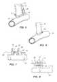
- FIG. 1is a perspective view of an anvil and a plurality of staples according to a first aspect of the present invention.
- FIG. 2is a perspective view of the anvil of FIG. 1 being inserted into a target vessel.
- FIG. 3is a perspective view of the anvil tenting a wall of a target vessel for an anastomosis procedure.
- FIG. 4is a perspective view of a graft vessel placed adjacent an exterior of the tented target vessel for the anastomosis procedure.
- FIG. 5is a perspective view of the staples being applied to the graft vessel and the target vessel during an anastomosis procedure.
- FIG. 6is a perspective view of the completed anastomosis according to the first aspect of the present invention.
- FIG. 7is a perspective view of a staple supported on a staple holding strip.
- FIG. 8is a side view of the staple and staple holding strip of FIG. 7 when the ends of the staple have been bent by contact with an anvil.
- FIG. 9is a perspective view of an anvil and staple according to another aspect of the present invention.
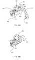
- FIGS. 10A and 10Bare side views of a plurality of staples supported on two examples of expandable staple holding strips.
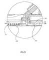
- FIG. 11is a perspective view of a portion of an anvil having a movable cutting device.
- FIG. 12is a side view of an anvil having an external cutting device.
- FIGS. 12A and 12Bare side views of a portion of an anvil and two cutting devices that snap onto the anvil.
- FIG. 13is a side view of a portion of an anvil with an extendable cutting device.
- FIG. 14is a side view of the anvil of FIG. 13 with the cutting device extended.
- FIG. 15is a side view of a portion of an anvil with an alternate extendable cutting device.
- FIG. 16is a side view of the anvil of FIG. 15 with the cutting device extended.
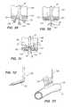
- FIG. 17is a perspective view of an anvil according to a second aspect of the invention being inserted into a target vessel.
- FIG. 18is a perspective view of the anvil of FIG. 17 positioning inside a target vessel and a clamp being advanced to clamp the wall of the target vessel between the anvil and the clamp.
- FIG. 19is a perspective view of a graft vessel being advanced to the target vessel with a continuous anastomosis staple while the anastomosis site on the target vessel is controlled by the anvil and clamp.
- FIGS. 20-22are side cross sectional views of the steps of performing the anastomosis with the continuous anastomosis staple shown in FIG. 19 .
- FIG. 23is a perspective view of the completed anastomosis performed as shown in FIGS. 19-22 .
- FIGS. 24-27are perspective views of the steps of an alternative anvil and clamp system for controlling an anastomosis site and forming an incision through the clamped tissue of the target vessel.
- FIG. 28is a perspective view of a system for controlling a tissue site and performing anastomosis according to the present invention.
- FIG. 29is a cross sectional view taken along line C-C of FIG. 28 , showing a first step of the anastomosis procedure.
- FIG. 30is a cross sectional view taken along line C-C of FIG. 28 , showing a second step of the anastomosis procedure.
- FIG. 31is a cross sectional view taken along line C-C of FIG. 28 , showing a third step of the anastomosis procedure.
- FIG. 32is a perspective view of an anvil according to another aspect of the present invention for use with sutures.
- FIG. 33is a perspective view of the anvil of FIG. 32 positioned within a target vessel and used to locate a plurality of suture at an anastomosis site.
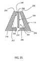
- FIG. 34is a side cutaway view of a first embodiment of an anvil, a cutter and a staple holder, where the anvil and staple holder are spaced apart from each other.
- FIG. 35is an end cross-section view of the anvil of FIG. 34 .
- FIG. 36is a side cutaway view of a portion of the anvil inserted into the lumen of a target vessel.
- FIG. 37is a side view of the cutter.
- FIG. 38is a perspective view of the cutter of FIG. 37 .
- FIG. 39is a side view of the distal end of a second embodiment of a cutter.
- FIG. 40is a side view of the distal end of a third embodiment of a cutter.
- FIG. 41is a side view of the distal end of a fourth embodiment of a cutter.
- FIG. 42is a side view of a portion of a fifth embodiment of a cutter.
- FIG. 43is a side view of the distal end of a sixth embodiment of a cutter.
- FIG. 43Ais a side view of another embodiment of a cutter.
- FIG. 43Bis a side view of another embodiment of a cutter.
- FIG. 44is a side cutaway view of the anvil and staple holder of FIG. 34 , where the cutter is in a first position.
- FIG. 45is a side cutaway view of the anvil and staple holder of FIG. 34 , where the cutter is in a second position.
- FIG. 46is a side cutaway view of the anvil and staple holder of FIG. 34 , where the cutter is in a third position.
- FIG. 47is a side cutaway view of the anvil and staple holder of FIG. 34 , where the cutter is in a fourth position.
- FIG. 48is a side cutaway view of the anvil and staple holder of FIG. 34 , where the cutter is in a fifth position.
- FIG. 49is a side cutaway view of a second embodiment of an anvil and a staple holder, where the anvil and staple holder are spaced apart from each other.
- FIG. 50is a side cutaway view of the anvil and staple holder of FIG. 40 , where the cutter is in a first position.
- FIG. 51is a side cutaway view of the anvil and staple holder of FIG. 40 , where the cutter is in a second position.
- FIG. 52is a side cutaway view of the anvil and staple holder of FIG. 40 , where the cutter is in a third position.
- FIG. 53is a side cutaway view of the anvil and staple holder of FIG. 40 , where the cutter is in a fourth position.
- FIG. 54is a side cutaway view of the anvil and staple holder of FIG. 40 , where the cutter is in a fifth position.
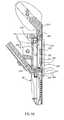
- FIG. 55is a side view of an anastomosis tool having a tissue effector and a handle.
- FIG. 56is a perspective view of the tissue effector of FIG. 55 in first position.
- FIG. 57is a perspective view of the tissue effector of FIG. 55 in a second position.
- FIG. 58is another perspective view of the tissue effector of FIG. 55 in the first position.
- FIG. 59is a perspective view of the tissue effector of FIG. 55 in the first position, with a graft vessel being connected to it.
- FIG. 59Ais a detail cross-section view of a cam lock used in the tissue effector of FIG. 55 , where the cam lock is in an open position.
- FIG. 59Bis a detail cross-section view of the cam lock of FIG. 59A in a closed position.
- FIG. 59Cis an end view of the left half of the tissue effector of FIG. 55 , in the closed position.
- FIG. 59Dis an end view of the right half of another embodiment of the tissue effector of FIG. 55 , in the closed position.
- FIG. 60is a detail side view of a portion of the tissue effector of FIG. 55 , showing an embodiment of a graft clip.
- FIG. 61is a detail end view of a portion of the tissue effector of FIG. 55 .
- FIG. 62is a side view of a vein knife used in the tissue effector of FIG. 55 .
- FIG. 63is a side view of a graft clip blade used in the tissue effector of FIG. 55 .
- FIG. 64is a cross-section view of section A-A of FIG. 57 .
- FIG. 65is a perspective view of a connector deployer used in the arm of FIG. 64 .
- FIG. 66is a side view of a portion of the arm of FIG. 64 as defined by the line B-B of FIG. 64 .
- FIG. 67is a perspective view of a staple configured to be deployed from the tissue effector of FIG. 55 .
- FIG. 68is a perspective view of a sled used in the tissue effector of FIG. 55 .
- FIG. 69is a bottom view of the sled of FIG. 68 .
- FIG. 69Ais a side view of the sled of FIG. 68 .
- FIG. 70is a side cross-section view of the handle of FIG. 55 in a first position.
- FIG. 71is a top view of a portion of a rocker utilized in the handle of FIG. 55 .
- FIG. 72is a side cross-section view of the handle of FIG. 55 in a second position.
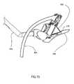
- FIG. 73is a perspective view of a completed anastomosis.
- FIG. 74is a perspective view of the tissue effector of FIG. 55 with a graft vessel loaded onto it.
- FIG. 75is a perspective view of the tissue effector of FIG. 74 , where the anvil of the tissue effector has been inserted into the lumen of a target vessel.
- FIG. 76is a perspective view of the tissue effector of FIG. 74 , after the graft vessel has been connected to the target vessel and before the anvil of the tissue effector has been removed from the lumen of the target vessel.
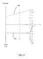
- FIG. 77is a graph qualitatively illustrating the positions of the distal slider and the proximal slider of the handle over time, with regard to an arbitrary point between them.
- FIG. 78is an exploded view of the handle of the anastomosis tool. The use of the same reference symbols in different figures indicates similar or identical items.
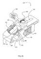
- FIG. 79is a perspective view of a retractor mount used in preparing a graft vessel for anastomosis.
- FIG. 80is a side cross-section view of the retractor mount of FIG. 79 .
- FIG. 80Ais a perspective view of the retractor mount of FIG. 79 mounted on a standard surgical retractor.
- FIG. 81is a perspective view of a transfer clamp assembly used in preparing a graft vessel for anastomosis, where the transfer clamp assembly includes a transfer clamp and an extension arm.
- FIG. 82is an end view of the transfer clamp of FIG. 81 in an open position.
- FIG. 82 ais a top cross-section view of the transfer clamp along the lines A-A of FIG. 82 .
- FIG. 83is a perspective view of the transfer clamp of FIG. 81 .
- FIG. 84is an end cross-section view of the transfer clamp of FIG. 81 in an open position, where cutting blocks are in a closed position relative to the transfer clamp.
- FIG. 85is a side cross-section view of the transfer clamp of FIG. 81 .
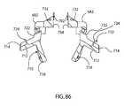
- FIG. 86is an end cross-section view of the transfer clamp of FIG. 81 in an open position, where cutting blocks are in an open position relative to the transfer clamp.
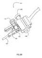
- FIG. 87is a perspective view of a graft manipulator.
- FIG. 88is a perspective view of the transfer clamp of FIG. 81 holding a graft vessel.
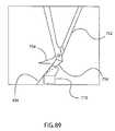
- FIG. 89is a schematic side view of the graft vessel held within the transfer clamp.
- FIG. 90is a perspective view of the transfer clamp of FIG. 81 holding a graft vessel, at the end of which flaps have been formed.
- FIG. 91is a perspective view of the transfer clamp of FIG. 81 holding a graft vessel, with cutting blocks in an open position.
- FIG. 92is a perspective view of an anastomosis tool connected to the retractor mount of FIG. 79 .
- FIG. 93is a perspective view of an anvil of a tissue effector, to which a shield is connected.
- the staple holderhas been omitted from the tissue effector for clarity.
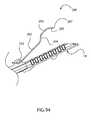
- FIG. 94is a side view of the anvil and shield of FIG. 93 .
- FIG. 95is a side cross-section view of the anvil and shield of FIG. 93 .
- FIG. 96is a perspective view of a sealer that is detachably connected to the anvil.
- FIG. 97is a schematic view of the deployment of the sealer of FIG. 96 .
- FIG. 98is a schematic view of another embodiment of a sealer prior to its deployment.
- FIG. 99is a schematic view of the sealer of FIG. 98 after deployment.
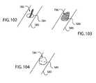
- FIG. 100is a schematic view of another embodiment of a sealer prior to its deployment.
- FIG. 101is a schematic view of the sealer of FIG. 100 after deployment.
- FIG. 102is a schematic view of another embodiment of a sealer prior to its deployment.
- FIG. 103is a schematic view of the sealer of FIG. 102 after deployment.
- FIG. 104is a schematic view of another embodiment of a sealer after deployment.
- FIG. 105is a schematic view of another embodiment of a sealer prior to its deployment.
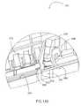
- FIG. 106is a detail perspective view of a tissue effector with a sealer detachably connected thereto, where the tissue effector includes a shield connected to the staple holder.
- FIG. 107is a side view of an exemplary clip used to seal the anvil entry hole adjacent to the anastomosis site, where that clip is secured to tissue.
- FIG. 108is a perspective view of the clip of FIG. 107 .
- FIG. 109is a perspective view of another embodiment of a clip, prior to its release.
- the anvil and staple holderare not shown for clarity.
- FIG. 110is a perspective view of the clip of FIG. 109 after its release.
- FIG. 111is a perspective view of a tissue effector configured to deploy user-selectable number of connectors.
- FIG. 112is a perspective view of the underside of the tissue effector of FIG. 111 .
- FIG. 113is a side cross-section view of the tissue effector of FIG. 111 .
- FIG. 114is a perspective view of a split deployer used in the tissue effector of FIG. 111 .
- FIG. 115is a side cross-section view of an embodiment of the tissue effector including another embodiment of a cutter, where the cutter is in a first position.
- FIG. 116is a side cross-section view of the tissue effector of FIG. 115 , where the cutter is in a second position.
- FIG. 117is a side cross-section view of the tissue effector of FIG. 115 , where the cutter is in a third position.
- FIG. 118is a side cross-section view of the tissue effector of FIG. 115 , where the cutter is in a fourth position.
- FIG. 119is a side cross-section view of an embodiment of the tissue effector including another embodiment of a cutter, where the cutter is in a first position.
- FIG. 120is a side cross-section view of the tissue effector of FIG. 119 , where the cutter is in a second position.
- FIG. 121is a side cross-section view of the tissue effector of FIG. 119 , where the cutter is in a third position.
- FIG. 122is a side cross-section view of the tissue effector of FIG. 119 , where the cutter is in a fourth position.
- FIG. 123is a detail perspective view of a location near distal end of the tissue effector, where the bending features are located on an upper surface of the anvil arm, and where the bending features corresponding to the toe of the anastomosis are offset toward one another.
- FIG. 124is a different detail perspective view of the tissue effector of FIG. 123 .
- FIG. 125is a side cross-section view of an embodiment of the tissue effector including another embodiment of a cutter, where the cutter is in a first position.
- FIG. 126is a side cross-section view of the tissue effector of FIG. 125 , where the cutter is in a second position.
- FIG. 127is a side cross-section view of the tissue effector of FIG. 125 , where the cutter is in a third position.
- FIG. 128is a side cross-section view of the tissue effector of FIG. 125 , where the cutter is in a fourth position.
- FIG. 129is a perspective view of an embodiment of a sealer.
- FIG. 130is a perspective view of an embodiment of a tissue effector that includes a graft affixer connected to the staple holder.
- FIG. 131is a side cross section view of the staple holder of FIG. 130 , where the tissue effector is in the open position.
- FIG. 132is a side cross-section view of the staple holder of FIG. 130 , where the tissue effector is in the closed position.
- FIG. 133is a perspective view of a graft vessel prepared for use with the tissue effector of FIG. 130 .
- FIG. 134is a perspective view of the tissue effector of FIG. 130 , with a graft vessel affixed thereto.
- FIG. 135is a perspective view of a completed anastomosis performed with the tissue effector of FIG. 130 and the graft vessel of FIG. 134 .
- FIG. 136is a perspective view of an exemplary applier that may be used to apply a clip to the anvil entry hole.
- FIG. 137is a top view of a clip that may be used with the applier of FIG. 136 , where that clip in is an open position.
- FIG. 138is a top view of the clip of FIG. 137 in a closed position.
- FIG. 139is a perspective view of the applier of FIG. 136 in use.
- FIG. 140is a perspective view of an exemplary anastomosis tool.
- FIG. 141is a detail view of an exemplary articulated shaft.
- FIG. 142is a perspective view of an exemplary anastomosis tool.
- FIG. 143is a detail cutaway view of an exemplary anvil and cutter of an anastomosis tool.
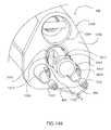
- FIG. 144is a perspective view of the distal end of an exemplary anastomosis tool, showing a graft vessel attached to the tissue effector of that tool.
- FIG. 145is a cross-section of an exemplary staple holder of a tissue effector, showing the relationship between a shield connected to the staple holder and the graft vessel.
- FIG. 146is a top view of a tissue effector having a deployment indicator.
- FIG. 147is a perspective view of another exemplary embodiment of a sled 482 .
- FIG. 148is a perspective cutaway view of an exemplary fluid-driven actuator within the handle of an anastomosis tool.
- FIG. 149is a schematic view of an exemplary fluid-driven actuator in a first, resting state.
- FIG. 150is a schematic view of an exemplary fluid-driven actuator in a second, clamping state.
- FIG. 151is a schematic view of an exemplary fluid-driven actuator in a third, firing state.
- FIG. 152is a cross-section view of a distal portion of an exemplary handle of an anastomosis tool.
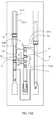
- FIG. 153is a cross-section view of a proximal portion of an exemplary handle of the anastomosis tool of FIG. 142 .
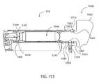
- FIG. 154is a cross-section view of an exemplary tissue effector of the anastomosis tool of FIG. 142 .
- FIG. 155is a perspective view of an exemplary tissue effector of the anastomosis tool of FIG. 142 in a graft preparation position.
- FIG. 156is a cutaway view of a connector bay in the staple holder showing an exemplary connector deployer.
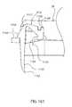
- FIG. 157is a top view of an exemplary clip used to seal the anvil entry hole adjacent to the anastomosis site, in an open configuration.
- FIG. 158is a side cross-section view of the clip of FIG. 157 held by an exemplary applier, where that applier is in a first position.
- FIG. 159is a side cross-section view of the clip of FIG. 157 held by the applier of FIG. 158 , where that applier is in a second position.
- FIG. 160is a side view of the clip of FIG. 157 in a closed configuration in the tissue of the target vessel.
- FIG. 161is a side view of an exemplary heel clip detachably connected to the staple holder, in an open position.
- FIG. 162is a side view of the exemplary heel clip of FIG. 161 detachably connected to the staple holder, after it has been deformed to a closed position.
- FIG. 163is a schematic view of a pressure regulation assembly in a first state.
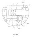
- FIG. 164is a schematic view of a pressure regulation assembly in a second state.
- FIG. 165is a schematic view of a pressure regulation assembly in a third state.
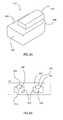
- an anvil 10includes a handle 12 and an anvil arm 14 extending from the handle 12 .
- the anvil arm 14may be oriented substantially perpendicular to the handle 12 , or oriented at a different angle.
- the anvil arm 14may be provided with one or more staple bending features 16 on opposite sides of the anvil arm 14 .
- the staple bending features 16each include a plurality of recesses 20 which receive the ends of staples 22 and cause the staple ends to bend over. At least one of the staple bending features 16 may be configured differently or omitted, if desired.
- the staples 22may be connected to a staple holding strip 24 .
- the staples 22are U-shaped and are arranged in a spaced apart parallel configuration such that the staples 22 all lie in a single plane. Alternately, the staples 22 may be shaped differently, and/or lie in one or more different planes.
- An exemplary anvil arm 14has a height and a width of about 2 mm or less, advantageously about 1 mm or less, and a length of about 2 to 15 mm, advantageously 5 to 12 mm.
- the length of the anvilwill vary depending on the diameter of the graft vessel selected.
- the length to width ratio of the anvil arm 14is substantially between 2:1 and 15:1. A different length to width ratio may be used, if desired.
- the staples 22have widths of about 0.2-3 mm.
- the staples 22have widths of substantially 2 mm or less.
- the leg lengths of the staples 22are substantially 0.2-3 mm. Alternately, other staple widths and/or leg lengths may be used.
- the anvil arm 14has a sharp distal end 28 for puncturing the tissue of a target vessel to insert the anvil arm 14 into the target vessel.
- the anvil arm 14is inserted into a pressurized or unpressurized target vessel 30 by puncturing the target vessel with the distal end 28 of the anvil arm 14 .
- the hole that is formed in the wall of the target vessel 30 by the anvil arm 14is small enough to prevent significant bleeding through the puncture site.
- the holeis closed by hand suturing.
- the holeis closed with a biocompatible glue, adhesive or the like.
- the holeis closed with a clip, clamp, or other implantable device that remains on the target vessel, as described in greater detail below.
- Such a devicemay be positioned on the outer surface and/or inner surface of the target vessel, and may extend into the hole.
- a device for closing the holemay be constructed from nitinol or other superelastic or pseudoelastic material, or from stainless steel or other material, where that device moves between a first configuration and a second configuration during deployment, and where the second configuration holds the hole closed.
- the holeis less than substantially 2 mm wide, and advantageously less than 1 mm wide.
- the anvil arm 14has a blunt distal end 28 that is inserted through a hole created with a separate instrument, by a different instrument connected to the anvil arm 14 , or by a sharp member connected to the anvil arm 14 that can be retracted into the anvil arm 14 or otherwise blunted or concealed after puncturing or creating an incision in the wall of the target vessel.
- the anvil arm 14may be pulled against an inner wall of the target vessel 30 , causing tenting of the thin tissue of the vessel wall as illustrated in FIG. 3 .
- This tenting of the vessel wallprovides control over the anastomosis site during an anastomosis procedure that is described with respect to FIGS. 4-6 .
- the target vessel wallneed not be tented in order to control the anastomosis site during the anastomosis procedure.
- a graft vessel 32is advanced to the anastomosis site and an end 34 of the graft vessel 32 is positioned adjacent an exterior surface of the target vessel 30 at the anastomosis site. At least part of the tented portion of the target vessel 30 is positioned within the perimeter of the end 34 of the graft vessel 32 .
- a staple holder 38is provided having two arms 40 which are pivotally connected to the handle 12 of the anvil 10 .
- the pivoting arms 40 of the staple holder 38may be connected to the handle 12 in a different way, or may be connected to a separate or additional device.
- the arms 40are spaced apart from one another across at least a part of their length.
- the graft vesselcan be positioned between the arms 40 . That is, the arms 40 are positioned on substantially opposite sides of the graft vessel. In this way, each arm 40 may be positioned against a flap at an end of the graft vessel, as illustrated in FIGS. 29-31 .
- the arms 40may be configured differently, if desired.
- the staple holder 38may be used to hold individual staples 22 and/or staple holding strips 24 .
- each arm 40 of the staple holder 38carries one row of staples 22 or one staple holding strip 24 , where the staples 22 are arranged in a substantially linear row.
- staples 22 or staple strips 24may be arranged in two or more rows, parallel or otherwise, on one or more arms 40 .
- the staples 22may be staggered on one or more arms, such that at least one row of staples 22 does not fall along a straight line.
- the staples 22may be arranged in a nonlinear manner on at least one arm 40 .
- the staples 22 or staple strips 24may be arranged or aligned in any manner on each arm 40 that results in a secure anastomosis between the graft vessel and the target vessel.
- the staples 22are inserted through the flaps at the end of the graft vessel 32 , or another portion of the graft vessel, and into the target vessel 30 by pivoting the arms 40 of the staple holder 38 towards the anvil arm 14 .
- the staple bending features 16are positioned in a configuration corresponding to the configuration of the staples 22 , such that each staple 22 engages a corresponding staple bending feature 16 during deployment.
- the staple holder 38is a mechanism that deploys connectors other than or in addition to staples 22 and/or staple holding strips 24 .
- FIG. 6illustrates a completed anastomosis between a target vessel 30 and a graft vessel 32 with a plurality of staples 22 .
- the spacing between the staples 22is approximately 1 to 4 mm. This spacing is similar to the spacing between sutures in a conventional sutured anastomosis. A different spacing between the staples 22 may be used if desired.
- the anvil arm 14After completion of the anastomosis, the anvil arm 14 is withdrawn from the target vessel 30 between adjacent staples 22 .
- the withdrawal of the anvil arm 14leaves a gap that is approximately the same as the spacing between adjacent staples. Accordingly, substantially no blood leakage occurs at the location where the anvil arm has been withdrawn.
- FIGS. 7 and 8illustrate one example of a staple 22 connected to a staple holding strip 24 .
- This staple 22includes barbed staple ends 52 extending from the front portion of the staple 22 and a C-shaped portion 54 extending from a rear of the staple 22 for connecting the staple 22 to the staple holding strip 24 .
- the staple holding strip 24includes a plurality of protrusions 56 for receiving the staples 22 .
- the C-shaped portion 54 of each staple 22is received around one of the protrusions 56 and is secured in place at one or more locations, such as by welds 58 or by a frangible linkage or connection. Alternately, the C-shaped portion 54 of each staple 22 may be secured to the staple-holding strip 24 in a different way. As shown in FIG.
- the staple 22may be detached from the staple holding strip 24 by the action of bending the barbed staple ends 52 such that the C-shaped portion 54 of the staple 22 splays outward and breaks apart from the corresponding protrusion 56 on the staple holding strip 24 , by bending a frangible connection between the staple holding strip and the staples to separate the staples, or any other known separation methods, such as melting of a connection between the staple and the staple holding strip.
- FIG. 9illustrates an alternate staple 22 a having inwardly curved barbed staple ends 52 a .
- the staple ends 52 aare themselves curved, the corresponding staple bending feature or features 16 a need not be curved to bend the ends 52 a of the staples 22 a .
- the staple bending features 16 a on each side of the anvil arm 14 amay be formed as a single longitudinal groove along the anvil arm 14 a , where the staple bending feature 16 a has a substantially flat surface.
- the staplemay be configured differently.
- two or more different kinds of staplesare deployed by the staple holder 38 in order to form a single anastomosis.
- a plurality of staples 22 aare positioned on an expandable staple holding strip called an expandable backbone 66 .
- the expandable backbone 66includes a plurality of elements 68 which are interconnected by one or more expanding members 70 .
- Each of the backbone elements 68is provided with a connecting diamond member 72 that is connected to one of the staples 22 a .
- each staple 22 ais connected to the corresponding diamond member 72 by a thin connecting section 74 .
- the expandable backbone 66allows the spacing between the staples 22 a to be adjusted for the particular anastomosis to be performed.
- the backbone 66allows expansion of the distance between staples from a distance of approximately 0.1 mm to a distance of approximately 1 to 4 mm, i.e., expansion of up to 40 times the original spacing. Alternately, the backbone 66 allows a different amount of expansion.
- the expanding backbone 66also includes two openings 76 at opposite ends which may be engaged by holding pins (not shown) on an anastomosis system or staple holder. The opening 76 allow the backbone 66 to be easily expanded by relative motion of the holding pins.
- the connecting diamond members 72are configured to collapse inwardly toward the backbone when the staples 22 a engage the staple bending surface or surfaces 16 a of the anvil.
- each diamond member 72forces the corresponding staple 22 a to separate from the diamond member 72 at a connecting section 74 .
- the connecting section 74is a frangible linkage connecting a staple 22 a to a corresponding diamond member 72 .
- FIG. 10Billustrates another example of staples 22 a detachably connected to a backbone 66 .
- the staples 22 aare each connected to the associated backbone elements 68 at two connecting sections 74 .
- the staples 22 a , backbone 66 , and associated componentsare substantially as described above with regard to FIG. 10A .
- FIG. 11shows a portion of an anvil arm 14 with a movable cutting device 44 .
- the cutting device 44includes a base 46 and a blade 48 .
- the base 46 of the cutting device 44is positioned in a longitudinal groove 50 in the anvil arm 14 .
- the cutting device 44may be moved longitudinally along the anvil arm 14 to form an incision in the target vessel.
- FIGS. 12 , 12 A, and 12 Billustrate external cutting devices that are advanced onto the anvil arm 14 after the anastomosis procedure and cut an incision in the target vessel from an exterior of the target vessel as the anvil arm 14 is withdrawn.
- a knife 62is positioned on a knife arm 64 that is movable along the handle 12 of the anvil. The knife 62 is moved downward in a direction substantially parallel to the longitudinal axis of the handle 12 until the knife 62 engages a recess 65 in the anvil arm 14 . The knife 62 is thereby positioned substantially at the anastomosis site.
- the end of the graft vesselis then placed substantially against the wall of the target vessel at the anastomosis site, over the knife 62 and knife arm 64 .
- the knife 62forms an incision in the target vessel.
- the knife 62 and knife arm 64exit the anastomosis site via the joint between the graft vessel and the target vessel.
- the withdrawal of the anvil arm 14 , knife 62 and knife arm 64leaves a gap in the wall of the target vessel that is approximately the same as the spacing between adjacent staples to minimize or eliminate leakage through that gap.
- the knife 62may be moveable relative to the handle 12 in at least one direction in addition to or instead of a direction substantially parallel to the longitudinal axis of the handle 12 .
- the knife 62may be moveable in a direction substantially parallel to the wall of the target vessel to create an arteriotomy in the target vessel at the junction between the graft vessel and the target vessel.
- FIGS. 12A and 12Billustrate two alternate examples of the knife 62 which snap onto a corresponding engagement surface 65 of the anvil arm 14 so that the knife 62 and anvil arm 14 are secured together for formation of the incision during removal of the anvil arm 14 from the anastomosis site.
- FIGS. 13-16illustrate two variations of extendable cutting devices for making an incision in the target vessel while withdrawing the anvil arm 14 from the target vessel.
- FIG. 13illustrates an anvil arm 14 b having a blade 78 connected to a flexible blade support 80 .
- the blade support 80is pulled in the direction of the arrow A with respect to the anvil arm 14 b , the blade 78 moves from a forwardly extending position shown in FIG. 13 to an upwardly extending position shown in FIG. 14 as a result of flexure of the blade support 80 .
- the blade 78 in the forwardly extending positionmay be used to form a small opening in the wall of the target vessel through which the anvil arm 14 is inserted into the target vessel.
- the blade 78is moved to an upwardly angled or a vertical position in which the blade 78 is used to form an incision in the target vessel as the anvil arm 14 b is removed from the target vessel.
- FIGS. 15-16illustrate an alternate example of an anvil arm 14 c having a blade 84 and a blade support 86 . While the anvil arm 14 c is inserted into the target vessel and during the anastomosis procedure, the blade 84 is positioned in a recess 88 in the anvil arm. The blade 84 may be moved from the position of FIG. 15 to the extended position of FIG. 16 by moving the blade support 86 in the direction of the arrow B with respect to the anvil arm. The blade 84 is flexible and stressed, such that freeing the blade 84 from the recess 88 causes the blade 84 to move to the extended position. Alternatively, the blade 84 may be extended automatically upon withdrawal of the anvil arm 14 when a blade tip 90 catches on an interior surface of the target vessel wall during withdrawal of the anvil arm.
- the extendable cutting devices shown in FIGS. 13-16are merely shown as examples of the type of cutting devices which may be used for making the incision. Once these cutting devices or blades have been extended from the anvil arm 14 , they may be fixed to perform cutting as the anvil arm 14 is removed from the target vessel or the blades may be movable along the anvil arm 14 to make an incision prior to removal of the anvil arm 14 from the target vessel.
- the anastomosis tool 300includes a handle 302 , a shaft 304 connected to the handle 302 , a cable housing 306 connected at one end to the handle 302 , and a tissue effector 400 connected to both the shaft 304 and the cable housing 306 .
- the anastomosis tool 300may be configured differently, if desired.
- the cable housing 306may be omitted, and the cable or cables (not shown) or other force transmission members that would otherwise extend therethrough are instead routed through the shaft 304 .
- the handle 302 and/or the tissue effector 400may be detachable from the shaft 304 to allow for interchangeability of these components.
- the same handle 302may be used to perform more than one anastomosis within a single patient, where a different tissue effector 400 may be connected to that handle 302 for each anastomosis.
- the handle 302may be constructed from materials that can be sterilized, such as by an autoclave, and reused.
- the handle 302may assume any appropriate configuration; the shape and configuration of the handle 302 described herein is exemplary and not limiting.
- the shaft 304may be a rigid hollow structure such as a tube of stainless steel, but may be shaped differently and/or fabricated from a different material. Further, the shaft 304 may be flexible at least in part, rather than rigid.
- the shaft 304may be omitted altogether, such that the handle 302 is connected to the tissue effector 400 by one or more cables or other force transmission members that would otherwise have extended through the shaft 304 .
- the handle 302may include a trigger 308 that provides for actuation of the anastomosis tool 300 based solely on a single input to that trigger 308 , as described in greater detail below.
- one or more other or additional inputsmay be utilized to actuate the anastomosis tool 300 .
- actuation of the anastomosis tool 300may be based on an input to one or more buttons in addition to the trigger 308 .
- the tissue effector 400includes an anvil 10 and a staple holder 38 .
- the tissue effector 400may be permanently fixed to the shaft 304 , or may be detachable from it such that is it decoupled from the handle 302 . That is, tissue effectors 400 may be interchangeable.
- the shaft 304is not provided, and the tissue effector 400 is directly coupled to the handle 302 .
- One end of the cable housing 306may be fixed to the staple holder 38 .
- the anvil 10 of the tissue effector 400may be as described above, or may be configured differently.
- the anvil 10may be formed from any material or combination of materials having a suitable stiffness.
- the anvil 10is formed from stainless steel.
- at least part of the lower portion of the anvil 10is formed from tungsten carbine for enhanced stiffness, and the upper portion of the anvil 10 is formed from stainless steel.
- Other or additional materials or combinationsmay be used.
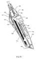
- the anvil 10also includes a cutter 200 that is moveable relative to the anvil 10 for making an incision in the wall of a target vessel. Referring to FIGS. 34 and 35 , a tissue stop 220 is formed into or connected to the anvil 10 .
- the portion of the anvil 10 distal to the tissue stop 220is configured to penetrate the wall of a target vessel, and may be referred to as the anvil arm 14 .
- a channel 246is defined within the anvil arm 14 , through which a cutter 200 is configured to move.
- the cutter 200is narrower than the channel 246 , such that interior surfaces 202 on either side of the channel 246 may guide the translation of the cutter 200 relative to the anvil arm 14 .
- translationas used in regard to the cutter 200 refers to motion of the cutter 200 in the distal or proximal direction, whether or not the cutter 200 or a portion thereof moves upward or downward during that motion.
- the direction substantially perpendicular to the longitudinal centerline of the anvil arm 14 toward the wall of the target vesselmay be referred to as “upward”, and the direction substantially perpendicular to the longitudinal centerline of the anvil arm 14 away from the wall of the target vessel may be referred to as “downward”.
- the positioning of the anvil arm 14 in useis not limited to an orientation in which these directions correspond to absolute directions measured relative to the ground.
- motion upward or downwardmay be referred to as “vertical” motion
- motion substantially parallel to the longitudinal centerline of the anvil arm 14may be referred to as “horizontal” motion.
- the anvil arm 14includes a contact surface 206 .
- the contact surface 206 of the anvil arm 14is placed substantially against the inner surface 203 of a target vessel 201 .
- the contact surface 206substantially defines a plane that is substantially parallel to the longitudinal centerline of the anvil arm 14 .
- the contact surface 206is contoured and/or oriented differently.
- An upper opening 248extends along at least a portion of the contact surface 206 in a direction substantially parallel to the longitudinal centerline of the anvil arm 14 , and opens into the channel 246 .
- the upper opening 248may divide the contact surface 206 into symmetrical or asymmetrical sections.
- the contact surface 206may be formed by two substantially planar surfaces, by one substantially planar surface and a differently-shaped surface, or by another set of surfaces. Additionally, the contact surface 206 may be formed by two thin edges, each edge occurring at the intersection of a wall of the upper opening 248 and an outer surface of the anvil arm 14 .
- the upper opening 248need not extend proximally any further than the tissue stop 220 . However, the upper opening 248 may extend proximal to the tissue stop 220 , if desired.
- a first lower opening 254 and a second lower opening 268are defined through a lower surface 256 of the anvil arm 14 .
- the lower surface 256 of the anvil arm 14may be substantially parallel to the contact surface 206 or may be oriented differently relative to the contact surface 206 .
- the first lower opening 254 and/or the second lower opening 268do not extend completely through the anvil arm 14 , and instead are depressions extending along at least part of a bottom surface 266 of the channel 246 .
- the cutter 200may be a thin, rigid member, shaped such that it can be held within and/or moved along the channel 246 in the anvil arm 14 .
- the cutter 200has a substantially constant width along its entire length. Alternately, the width of the cutter 20 may vary along its length.
- the cutter 200may be made of metal, ceramic, plastic, or other material, or from a combination of different materials.
- a sharp projection 208extends upward from the cutter 200 at or near its distal end.
- the projection 208is substantially triangular, but may be shaped differently.
- the projection 208may be smooth or serrated, or otherwise shaped or formed.
- a portion of the projection 208may be ground or otherwise honed to a sharp edge to facilitate the motion of the projection 208 through the tissue of the wall of a target vessel, as described in greater detail below.
- the cutter 200is composed of a material that can be sharpened adequately to cut tissue.
- the cutter 200may be flexible, at least in part.
- the projection 208may be located at a different position on the cutter 200 than at or near its distal end.
- An additional sharp point(not shown) may be provided at the distal end of the cutter 200 , extending in a distal direction, in order to create an initial puncture or incision in the wall of the target vessel. Such a point may be as described in U.S. patent application Ser. No. 10/134,081, which is herein incorporated by reference in its entirety.
- One or more additional projections 208may be provided, if desired.
- two or more projections 208may extend upward from the cutter 200 . Where multiple projections 208 are used, they may cooperate with one another to create an incision in the wall of the target vessel.
- a second projection 208extends upward from the cutter 200 proximal to a first projection 208 .
- the projections 208are both substantially the same triangular shape and the same size. However, the projections 208 may be shaped and sized differently.
- the projections 208are both substantially planar, and are aligned such that both projections 208 lie in substantially the same plane. Alternately, at least one projection 208 is not substantially planar.
- Each projection 208may include at least one sharpened or beveled edge 209 oriented to engage and incise the wall of the target vessel when the cutter 200 is translated, as described below.
- at least two projections 208extend upward from the cutter 200 .
- the projections 208each have a barb 211 at the tip. However, the barb 211 may be omitted from some or all of the projections 208 .
- Under the barb 211a sharpened or beveled edge 209 extends downward and proximally.
- the edge 209may be straight or curved. The upper end of the edge 209 is distal to the lower, proximal end of the corresponding barb.
- each projection 208is oriented to engage and incise the wall of the target vessel when the cutter 200 is translated.
- at least two projections 208extend upward from the cutter 200 , at least one of which has a barb 211 at its tip.
- the edge 209 associated with each projection 208is more curved than the edge 209 shown in FIG. 40 .
- the edge 209is substantially straight, or gently curved, or positioned on a portion of a larger curved segment 213 extending downward from and proximal to the barb 211 .
- a number of projections 208may be placed along a length of the cutter 200 .
- This lengthmay be comparable to the desired length of the incision in the wall of the target vessel.
- These projections 208may be substantially triangular as shown, or may be shaped differently. Where more than one projection 208 is used on the cutter 200 , the projections 208 need not have the same configuration. For example, projections 208 such as the exemplary projections 208 shown in FIGS. 39-41 may be mixed together on the same cutter 200 . Alternately, one or more of the projections 208 are moveable relative to the cutter 200 , such that one or more projections 208 can be moved upward or downward relative to the cutter 200 .
- the projections 208 extending upward from the cutter 200each are substantially planar, and are aligned such that not all of the projections 208 lie in the same plane.
- the projections 208may create a wider incision in the wall of the target vessel than would be created if the projections 208 were substantially aligned.
- one set of projections 208may be aligned substantially in a first plane, and a second set of projections 208 may be aligned substantially in a second plane substantially parallel to the first plane.
- the second plane and the first planemay be oriented differently relative to one another, if desired.
- none of the projections 208lie in a common plane with one or more other projections 208 .
- the cutter 200need not be translated as far to make an incision in the wall of the target vessel as it would if only a single projection 208 were used, as described in greater detail below.
- This cutter 200is an assembly that includes a projection 208 rotatable or otherwise movable from a stowed position in which it is substantially completely within the channel 246 in the anvil arm 14 (shown in FIG. 115 ) to an active position in which at least a portion of the projection 208 extends upward from the channel 246 in the anvil arm 14 (shown in FIGS. 116-117 ).
- the projection 208may include an edge 209 that is beveled or sharpened, where that edge 209 may be oriented at least partially distally when the projection 208 is in the active position.
- the edge 209may be oriented at least partially proximally when the projection 208 is in the active position.
- the orientation of the edge 209 when the projection 208 is in the active positionis related to the direction of motion of the projection 208 as it creates an incision in the target vessel 580 , as is described in greater detail below.
- the proximally-facing surface of the projection 208may be blunt.
- the distally-facing surface of the projection 208may be blunt.
- a member 848is connected to the projection 208 .
- the member 848is at least partially rigid.
- An aperture 849is defined through the projection 208 .
- the distal end of the member 848 , or a portion of the member 848 near its distal end,is received into or through that aperture 849 to connect to the projection 208 .
- the member 848is connected to the projection 208 in a different way.
- the member 848extends along the channel 246 in the anvil arm 14 .
- a pusher 850also extends along the channel 246 in the anvil arm 14 .
- the pusher 850is a substantially rigid body, having a distal end that is configured to engage the projection 208 .
- the distal end of the pusher 850may be beveled or otherwise shaped such that at least the upper portion of that distal end is angled or curved proximally.
- the distal end of the pusher 850is configured to remain substantially in contact with the projection 208 in both the stowed position and the active position. Alternately, the pusher 850 engages the projection 208 in a different manner.
- the aperture 849 in the projection 208may be located at a position lower than the longitudinal centerline of the pusher 850 . Alternately, the aperture 849 is positioned differently relative to the pusher 850 .
- a spring 852may be connected to or otherwise associated with the pusher 850 .
- the spring 852may be a leaf spring, a compression spring, or any other suitable type of spring or biasing element.
- the spring 852is configured to press the pusher 850 downward against the bottom surface 266 of the channel 246 in the anvil arm 14 when the projection 208 is in the stowed position. In this way, the pusher 850 is held substantially in place when the projection 208 is in the stowed position.
- the spring 852is also configured to release the pusher 850 and allow it to translate when the cutter 200 is in the active position.
- a button 854is configured to press the spring 852 downward and thereby hold the pusher 850 in place when the projection 208 is in the stowed position, and is movable to a position in which it no longer presses the spring downward and thereby releases the pusher 850 when the projection 208 is in the active position.
- the spring 852may be connected to the button 854 rather than the pusher 850 .
- a stop 856may be connected to or formed into the channel 246 of the anvil arm 14 , where that stop 856 is configured to engage the spring 852 or other portion of the cutter 200 and arrest its motion at a particular location, as described in greater detail below.
- a cavity 262may be defined within the staple holder 38 or a separate component connected to the staple holder 38 .
- a post 258is positioned at the upper end of the cavity 262 , where the post 258 is oriented downward.
- a biasing element 260is connected at one end to the post 258 .
- the biasing element 260may be a coil spring, a leaf spring, a different type of spring, an elastomer, a wire form, or other structure or mechanism capable of exerting a biasing force.
- the biasing element 260is positioned within and protected by the cavity 262 , where the cavity 262 is used.
- the cavity 262may be a cylindrical opening having a diameter substantially the same as the outer diameter of the biasing element 260 , such that the cavity 262 restricts the biasing element 260 to motion substantially along the axis of the cavity 262 and thus directs the force exerted by the biasing element 260 in a substantially downward direction, preventing bending or other undesirable motion of the biasing element 260 .
- the end of the biasing element 260 that is not connected to the post 258contacts the cutter 200 .
- the biasing element 260may be a compression spring that is compressed between the post 258 and the cutter 200 , resulting in a force on the cutter 200 that biases the cutter 200 downward.
- the cutter 200is slidable relative to the biasing element 260 , such that the biasing element 260 exerts a downward force on the cutter 200 at different locations along its upper surface 252 as the cutter 200 translates.
- the biasing element 260exerts a downward force on the cutter 200 at different locations along its upper surface 252 as the cutter 200 translates.
- at least the distal end of the cutter 200is biased downward throughout its translation along the anvil 10 .
- the entire cutter 200may be biased downward, if desired.
- the post 258is omitted, and the biasing element 260 is fixed to an upper surface of the cavity 260 .
- the biasing element 260is omitted, and the cutter 200 is biased downward in another way.
- the cutter 200may be constructed from an elastic or superelastic material that is formed in such a way as to produce a downward bias.
- the cutter 200is an assembly that includes a projection 208 rotatable or otherwise movable from a stowed position in which it is substantially completely within the channel 246 in the anvil arm 14 (shown in FIG. 119 ) to an active position in which at least a portion of the projection 208 extends upward from the channel 246 in the anvil arm 14 (shown in FIGS. 120-121 ).
- the projection 208may include an edge 209 that is beveled or sharpened, where that edge 209 may be oriented at least partially distally when the projection 208 is in the active position.
- the edge 209may be oriented at least partially proximally when the projection 208 is in the active position.
- the orientation of the edge 209 when the projection 208 is in the active positionis related to the direction of motion of the projection 208 as it creates an incision in the target vessel 580 , as is described in greater detail below.
- the proximally-facing surface of the projection 208may be blunt.
- the distally-facing surface of the projection 208may be blunt.
- the projection 208includes a lobe 858 defined therein or connected thereto, where the lobe 858 is located on the lower portion of the projection 208 with reference to the position of the projection 208 in the stowed position.
- the lobe 858may be curved or rounded.
- a slot 860is located in the bottom surface 266 of the channel 246 in the anvil arm 14 .
- the slot 860may extend completely through that bottom surface 266 , or may simply be a depression or other feature defined in that bottom surface 266 .
- An aperture 849is defined in the projection 208 .
- a clip 862is connected to the projection 208 through the aperture 849 .
- the clip 862may be U-shaped, or shaped in any other suitable manner.
- the clip 862may be configured to slide along at least one track 864 defined in or connected to at least one interior surfaces 202 of the channel 264 .
- a pusher 850also extends along the channel 246 in the anvil arm 14 .
- the pusher 850is a substantially rigid body, having a distal end that is configured to engage the projection 208 .
- the distal end of the pusher 850may be beveled or otherwise shaped such that at least the lower portion of that distal end is angled or curved proximally.
- the distal end of the pusher 850is configured to remain substantially in contact with the projection 208 in both the stowed position and the active position. Alternately, the pusher 850 engages the projection in a different manner.
- the aperture 849 in the projection 208may be located at a position lower than the longitudinal centerline of the pusher 850 .
- the aperture 849is positioned differently relative to the pusher 850 .
- the pusher 850may be substantially restrained when the projection 208 is in the stowed position and substantially freed when the projection 208 is in the active position.
- the cutter 200is an assembly that includes a projection 208 rotatable or otherwise movable from a stowed position in which it is substantially completely within the channel 246 in the anvil arm 14 (shown in FIG. 125 ) to an active position in which at least a portion of the projection 208 extends upward from the channel 246 in the anvil arm 14 (shown in FIGS. 126-127 ). At least one edge 209 of the projection 208 may be beveled or otherwise sharpened.
- a member 848is connected to the projection 208 .
- the member 848is a cable or any other appropriate structure or mechanism.
- the member 848may be at least partially rigid.
- An aperture 849is defined through the projection 208 .
- the distal end of the member 848 , or a portion of the member 848 near its distal end,is received into or through that aperture 849 to connect to the projection 208 .
- the member 848is connected to the projection 208 in a different way.
- the member 848extends along the channel 246 in the anvil arm 14 .
- the projection 208includes a lobe 858 defined therein or connected thereto, where the lobe 858 is located on the lower portion of the projection 208 with reference to the position of the projection 208 in the stowed position.
- the lobe 858may be curved or rounded.
- a notch 859may be located between the lobe 858 and the remainder of the projection 208 .
- the notch 859may be curved, rounded, angled or otherwise configured.
- a slot 860is located in the bottom surface 266 of the channel 246 in the anvil arm 14 .
- the slot 860may extend completely through that bottom surface 266 , or may simply be a depression or other feature defined in that bottom surface 266 .
- the projection 208includes two sharp edges 209 .
- a centerpiece 868may be secured within the channel 246 .
- the centerpiece 868may be connected to one or more pins 870 that are connected to or formed into the anvil arm 14 .
- the centerpiece 868is positioned at least partially above the channel 246 , and/or may extend laterally from at least one edge of the channel 246 , as shown in FIG. 143 .
- the centerpiece 868includes a slot 872 in its upper surface to allow the projection 208 to extend therethrough, and includes a longitudinally-extending free space 874 that allows the projection 208 to travel longitudinally therethrough.
- a receiving space 876is defined at or near the distal end of the centerpiece 868 , oriented downward. The receiving space 876 is located distal to a first cam surface 878 , which is positioned lower than the uppermost part of the receiving space 876 . Alternately, the centerpiece 868 is not used.
- an interior surface 202is located on each side of the channel 246 .
- Each interior surface 202may be substantially planar, curved, or may be shaped differently. Further, each interior surface 202 may be oriented at an angle to vertical or substantially vertical.
- the interior surfaces 202may be formed such that the channel 246 is substantially bilaterally symmetrical, or may be formed to result in a channel 246 that is not bilaterally symmetrical.
- the interior surfaces 202 of the channel 246 within the anvil arm 14may include raised features 204 that correspond to depressed staple bending features (not shown) on the outer surface of the anvil arm 14 .
- the depressed staple bending featuresresult in corresponding raised features 204 on the interior surface 202 of the channel 246 .
- the raised features 204do not interfere with the motion of the cutter 200 through the channel 246 . Alternately, the raised features 204 are not present on the interior surface 202 of the channel 246 .
- a shield 290may be connected to the anvil arm 14 , at or near the proximal end of the anvil arm 14 .
- the shield 290may be connected to the anvil arm 14 in proximity to the tissue stop 220 .
- the shield 290may be connected to a different location on the anvil arm 14 , or to a portion of the anvil 10 other than the anvil arm 14 .
- the junction between the shield 290 and the anvil arm 14performs the function of the tissue stop 220 , and a separate tissue stop 220 is not provided.
- the shield 290may be connected to or formed into the anvil arm 14 in any appropriate manner.
- the shield 290may be pressure-fit to the anvil arm 14 at or near the tissue stop 220 .
- the shield 290may be connected to the anvil arm 14 by welding, by adhesive, or by any other appropriate structure, mechanism, or method.
- the proximal end of the shield 290is connected to the anvil arm 14 , and the distal end of the shield 290 is free.
- the shield 290is connected to the anvil arm 14 in a different orientation.
- the shield 290may be connected to the anvil arm 14 such that the free end of the shield 290 is biased upward relative to the anvil arm 14 .
- the free end of the shield 290need not be biased upward, or in any other direction, relative to the anvil arm 14 .
- the shield 290may be biased downward relative to the anvil arm 14 .
- the shield 290is configured to be positioned at least partially adjacent to the outer surface of the target vessel during the anastomosis procedure, as described in greater detail below.
- a proximal element 292 of the shield 290is substantially straight, such that it substantially can contact the outer surface of the target vessel during the anastomosis procedure.
- a raised element 293 of the shield 290 at or near its distal endis raised relative to the proximal element 292 of the shield 290 .
- a first ramp element 294 of the shield 290connects the proximal element 292 of the shield 290 to the raised element 293 of the shield 290 .
- a second ramp element 295may extend distally and downward from the raised element 293 of the shield 290 .
- At least a portion of the second ramp element 295is configured to contact the outer surface of the target vessel. This contact provides a limit to the motion of the shield 290 relative to the anvil arm 14 and causes the raised element 293 to be spaced apart from the outer surface of the target vessel.
- the second ramp element 295or distal end of the raised element 293 if the second ramp element 295 is not used, is blunt to prevent damage to the outer surface of the target vessel upon contact therewith.
- the shield 290may be configured and/or shaped differently.
- an aperture 296extends substantially longitudinally along at least a portion of the shield 290 .
- the aperture 296has a closed perimeter, or alternately may be open ended.
- the aperture 296is substantially aligned with the channel 246 in the anvil arm 14 .
- the projection 208 of the cutter 200extends above the contact surface 236 of the anvil arm 14 , at least a portion of the aperture 296 receives at least part of the projection 208 and allows it to slide freely.
- the aperture 296extends along the shield 290 a sufficient distance to allow the projection 208 to slide freely throughout its entire travel, as described in greater detail below.
- a tip element 297may be located at or near the distal end of the shield 290 , oriented substantially transversely and closing the distal end of the aperture 296 .
- the tip element 297may be oriented differently, if desired.
- the aperture 296need not be provided, such as where the shield 290 is configured to remain above and out of contact with the projection 208 throughout its path of motion.
- the shield 290may be composed of polyethylene such that it is both flexible and durable. However, any other suitable material may be utilized if desired.
- the shield 290may be connected to the staple holder 38 .
- the shield 290includes a snap feature 898 that connects to an aperture 900 in the staple holder 38 .
- the snap feature 898is compressible for insertion into the aperture 900 , and expands after it is released. Friction between the snap feature 898 and the aperture 900 , and/or interference between portions of the snap feature 898 above the aperture 900 and the structure in proximity to the aperture 900 , hold the shield 290 in place.
- This snap feature 898is utilized for ease of assembly; the shield 290 is connected to the staple holder 38 throughout the anastomosis procedure.
- the shield 290is connected to the staple holder 38 in a different manner. Alternately, the shield 290 is detachable from the staple holder 38 .
- the shield 290extends upward and proximally from its point of connection to the staple holder 38 , then curves to extend downward and distally; this portion of the shield 290 may be referred to as the hinge 902 .
- the remainder of the shield 290extends substantially distally from the hinge 902 substantially as described above.
- the shield 290may include an aperture 296 therein and/or be otherwise configured substantially as described above. Further, the shield 290 is utilized, and removed from the anastomosis site, in substantially the same manner as the configuration of shields 290 described above.
- At least the hinge 902 of the shield 290is composed of polyethylene or other flexible material. In this way, the hinge 902 can flex to allow the tissue effector 400 to move from the open position to the closed position.
- FIGS. 144-145another example of a shield 290 connected to the staple holder 38 is shown.
- the shield 290is connected to a location at or near the distal end of the staple holder 38 .
- the shield 290is connected to the staple holder 38 by a hinge 966 .
- the hinge 966may be oriented in a substantially transverse direction. Where the hinge 966 is used, the shield 290 may be flexible or rigid. Alternately, the shield 290 may be flexible, and fixed to the staple holder 38 . Alternately, the shield 290 is connected to the staple holder 38 in any other suitable manner.
- the tissue effector 400may include one or more other features.
- the anvil 10 and the staple holder 38are configured to snap together when the tissue effector 400 moves to the closed position.
- Any suitable mechanism or structuremay be used to hold the tissue effector 400 in the closed position.
- a first tab 904extends from the tissue stop 220 or other portion of the anvil 10
- a second tab 906extends from a corresponding location on the staple holder 38 .
- the tissue effector 400moves to a closed position, at least one of the tabs 904 , 906 flexes to accommodate the other tab 904 , 906 , until the first tab 904 is located above the second tab 906 .
- the tabs 904 , 906are configured such that the tissue effector 400 cannot easily re-open. In this manner, the tissue effector 400 is positively held in the closed position.
- a safety feature 210may be connected to the underside of the anvil 10 .
- the safety feature 210is biased toward the anvil 10 and the cutter 200 .
- the safety feature 210may be biased into the channel 246 within the anvil 10 .
- the safety feature 210is connected to a different location, such as the underside of the anvil arm 14 .
- the safety feature 210may be flexible or rigid.
- the safety feature 210includes a tip 212 that is oriented substantially transverse to the longitudinal centerline of the cutter 200 . Alternately, the tip 212 may be oriented in a different direction.
- the cutter 200may include a safety recess 214 defined in it, corresponding to the tip 212 of the safety feature 210 .
- the tip 212is shaped and sized such that it can engage the safety recess 214 .
- the tip 212may be a bar or rod oriented substantially transverse to the direction of translation of the cutter 200 , or may be shaped or oriented differently.
- the staple holder 38has not yet been moved into position to perform anastomosis.
- the tip 212 of the safety feature 210is biased upward to engage the safety recess 214 .
- the engagement between the safety recess 214 and the tip 212 of the safety feature 210substantially prevents translation of the cutter 200 within the channel 246 .
- the cutter 200 and the projection 208are prevented from deploying until the staple holder 38 has been moved into the appropriate position relative to the anvil arm 14 , and inadvertent actuation of the cutter 200 is prevented.
- the cutter 200may include an engagement member 216 extending upward from a location at or near its proximal end.
- the engagement member 216instead may extend downward from the cutter 200 or to the side of the cutter 200 . Further, the engagement member 216 may be positioned at a location other than at or near the proximal end of the cutter 200 .
- the engagement member 216is configured to engage at least a portion of a corresponding receiver 218 in the staple holder 38 . Thus, after engagement between the engagement member 216 and the receiver 218 , translation of the receiver 218 results in translation of the cutter 200 .
- the receiver 218is a structure that is at least partially open on its underside and that includes at least one surface 219 configured to engage the engagement member 216 . As shown in FIG.
- the surface 219is a partially-curved surface shaped to receive the curved upper end of the engagement member 216 .
- the receiver 218may be a flat vertical surface, a curved surface, a structure such as an inverted cup that is open on its underside and that has a wall or walls encircling the engagement member 216 , or any other structure or mechanism capable of engaging the engagement member 216 and urging it distally.
- the receiver 218may be defined in a sled 482 , which is described in greater detail below.
- an anvil insert 222is fixed to the anvil 10 .
- the anvil 10is wider proximal to the anvil arm 14 , open at its top with a space therein.
- the anvil insert 222can be inserted into the anvil 10 through the open top of the anvil 10 , such that the anvil insert 222 is partially or completely positioned within the anvil 10 .
- the anvil insert 222may be connected to the anvil 10 in another way.
- the anvil insert 222is connected to and capable of motion relative to the anvil 10 .
- the anvil insert 222instead may be connected to the proximal end of the anvil arm 14 , or another location on the anvil arm 14 .
- a cavity 228is defined within the anvil insert 222 .
- An aperture 230is defined through the distal end of the anvil insert 222 into the cavity 228 , connecting the channel 246 in the anvil arm 14 and anvil 10 to the cavity 228 .
- the cutter 200extends through the aperture 230 , such that the distal end of the cutter 200 is positioned within the channel 246 and the proximal end of the cutter 200 is positioned within the cavity 228 .
- a cutter stop 236may be formed into or connected to the anvil insert 222 , or formed into or connected to the anvil 10 itself or another structure or mechanism.
- the cutter stop 236may engage the proximal end of the cutter 200 if the cutter 200 is moved proximally to a defined position within the cavity 228 , thereby restricting its proximal translation.
- the anvil 10may include one or more attachment features 270 .
- the attachment features 270provide a location for attachment of one or more cables or other force transmission structures or mechanisms.
- the attachment features 270may be one or more passages 270 through the cutter stop 236 .
- the cutter stop 236may include two or more spaced-apart members. If so, the attachment features 270 may be substantially aligned with one another, or offset from one another. However, the cutter stop 236 may be a single member, if desired.
- one or more of the attachment features 270are separate from the cutter stop 236 , and are positioned at a different location on the anvil 10 .
- one or more of the attachment features 270may extend in a direction from the anvil 10 that is other than upward.
- the configuration of the attachment features 270is related to the configuration of the cable or other force transmission structure or mechanism attached to it, such that the connection between them is secure.
- the cutter stop 236includes two spaced-apart members, and the attachment features 270 are passages through the upper portion of each member of the cutter stop 236 .
- Two separate cablesare connected to the attachment features 270 .
- the end of each cableis passed through one of the attachment features 270 , after which it is welded, connected with adhesive, clamped, tied or otherwise secured to the cutter stop 236 .
- a single first cableis passed through each of the attachment features 270 , such that the free ends of the first cable are spaced apart from the attachment features 270 .
- the cablemay be welded, connected with adhesive, clamped, tied or otherwise secured to the cutter stop 236 , if desired.
- the force transmission member or membersmay be connected to the anvil 10 in a different manner and/or location.
- the anvil 10extends proximally to a pivot point such as a pin 226 .
- the pivot pointmay be any other structure or mechanism that allows the anvil 10 to rotate about it.
- the pivot pointmay be a four-bar linkage or other mechanism rather than the pin 226 .
- the staple holder 38 and the anvil 10may be movable relative to one another in a simple manner such as rotation, or in a more complex manner.
- the anvil insert 222extends to the pin 226 instead of or in addition to the anvil 10 .
- the pin 226pivotally connects the staple holder 38 to the anvil 10 .
- the pin 226may be formed into or otherwise fixed to the staple holder 38 or anvil 10 , if desired.
- the anvil 10 and/or anvil insert 222may extend still further proximally from the pin 226 .
- the anvil 10extends proximally to the pin 226 .
- the anvil insert 222also extends proximally to the pin 226 , and additionally extends as far as or further proximally to the proximal end of the anvil 10 .
- the staple holder 38 and the anvil 10may be connected to one another in any other suitable manner and/or in any suitable location.
- the staple holder 38 and the anvil 10may be connected to one another at the junction between the tissue effector 400 and the shaft 304 .
- the staple holder 38 and/or anvil 10may be movable toward the other.
- the staple holder 38is substantially fixed relative to the anvil 10 . If so, the tissue effector 400 is substantially in the closed position throughout the anastomosis procedure. Fabrication and/or operation of the anastomosis tool 300 may be simplified if the tissue effector 400 remains in substantially the same position throughout the anastomosis procedure.
- a proximal portion of the anvil insert 222may be bent upward relative to a distal portion of the anvil insert 222 .
- the proximal portion of the anvil insert 222may be referred to as the spine 272 .
- the spine 272need not be bent upward relative to the proximal portion of the anvil insert 222 , and instead may be bent downward or oriented substantially parallel to the proximal portion of the anvil insert 222 .
- the spine 272is a separate structure or mechanism that is connected to the anvil insert 222 .
- a post 274may be defined in or connected to the spine 272 .
- the post 274may be cylindrical, or may be shaped differently.
- the spring 276is a coil spring, but may be a different type of spring if desired.
- the other end of the spring 276is connected to the staple holder 38 , such as to an attachment member 275 defined in or connected to the staple holder 38 .
- the attachment member 275may be cylindrical, or may be shaped differently.
- the spring 276may be connected to the post 274 and/or to the attachment member 275 by hooking an end of the spring 276 to at least one of the post 274 and the attachment member 275 , by welding, by adhesive, or by any other appropriate structure, mechanism or method.
- the spring 276may be connected to the staple holder 38 and/or the spine 272 in a different way, if desired.
- the spring 276is sized and configured to be in tension, so as to bias the tissue effector 400 to an open position. That is, the spring 276 presses the staple holder 38 about the pin 226 , toward the spine 272 of the anvil insert 222 .
- any other suitable structure, mechanism or methodmay be used to bias the tissue effector 400 to the open position. Alternately, the tissue effector 400 is not biased to the open position.
- buttons 278are connected to the spine 272 .
- the wing or buttons 278may be spaced apart from the spine 272 and connected to it by one or more connection members 280 .
- the buttons 278each may be sized and shaped for contact with a user's finger.
- two buttons 278may be sized and shaped such that a user may conveniently press one with a thumb and the other with a forefinger.
- the precise shape and size of the buttons 278is not critical to the invention.
- at least one button 278is connected to a cog 282 that in turn connects to the shaft 304 of the anastomosis tool 300 , as described in greater detail below.
- the cog 282includes one or more teeth 284 .
- the cog 282is substantially circular, and the teeth 284 extend substantially radially outward from it.
- the staple holder 38includes two arms 402 , where those arms 402 are spaced apart from one another along at least part of their length, and/or at least at one end. More or fewer arms 402 may be provided.
- the arms 402extend distally from the remainder of the staple holder 38 . However, the arms 402 may be positioned differently, if desired.
- the arms 402are generally linear in configuration, and the longitudinal centerlines of the arms 402 are substantially parallel to one another. However, the arms 402 may be shaped differently and/or oriented differently relative to one another.
- One or more of the arms 402may be angled relative to a horizontal plane; for example, to facilitate connecting the flaps of the graft vessel to the wall of the target vessel.
- the arms 402are spaced apart from one another along at least part of their length and/or at least at one end to allow a graft vessel 404 to be placed between them, and to allow the tissue effector 400 to be freed from the completed anastomosis.
- the arms 402may be substantially fixed relative to one another. Alternately, at least one arm 402 may be movable relative to the other arm 402 .
- each arm 402may include a flap receiving surface 406 .
- Each flap receiving surface 406is substantially flat across at least a portion of its area.
- Each flap 408 at the end of the graft vessel 404is placed onto a corresponding flap receiving surface 406 , and the main body of the graft vessel 404 extends between the arms 402 of the staple holder 38 .
- each flap 408is substantially flat against the corresponding flap receiving surface 406 .
- One or more of the flap receiving surfaces 406may include a ridged region 413 that has individual ridges 416 spaced apart from one another. The individual ridges 416 may be parallel to one another, or oriented differently. The ridges 416 extend away from the flap receiving surface 406 .
- each flap receiving surface 406includes a ridged region 413 in proximity to its inner edge.
- the term “inner”refers to proximity to the space between the arms 402
- the term “outer”refers to distance from the space between the arms 402 .
- two flaps 408are present at the end of the graft vessel 404 .
- These flaps 408may be created in any appropriate manner, such as by incising the end of the graft vessel 404 with a scalpel.
- the end of the graft vessel 404may have more than two flaps 408 .
- the end of the graft vessel 404may have a single flap 408 . That is, a single incision may be made at the end of the graft vessel 404 , substantially parallel to its centerline.
- a single flap 408is created that extends substantially continuously around the circumference of the end of the graft vessel 404 , where the opposite ends of the flap 408 are adjacent to the incision.
- one or more spikes 410may extend outward from at least one of the flap receiving surfaces 406 .
- the flaps 408As at least one of the flaps 408 is placed onto the corresponding flap receiving surface 406 , one or more of the spikes 410 penetrate that flap 408 partially or completely, thereby assisting in holding the flap 408 in place against the flap receiving surface 406 .
- no flapsare created at the end of the graft vessel 404 . Rather, an end of the graft vessel 404 is simply everted onto the flap receiving surfaces 406 , spikes 410 and/or other part of the staple holder 38 . Where the end of the graft vessel 404 is everted, the anastomosis procedure is performed in substantially the same manner as if one or more flaps 408 were utilized.
- a graft clip 412is connected to each arm 402 .
- Each graft clip 412may be configured to rotate relative to the corresponding arm 402 .
- each graft clip 412is pivotally connected to the corresponding arm 402 at or near the outer edge 414 of that arm 402 .
- at least one graft clip 412is movable relative to the corresponding arm 402 in a different way, such as by sliding.
- at least one graft clip 412is initially a separate component from the arm 402 , and is connectable to the corresponding arm 402 .
- Each graft clip 412is moveable between an open position and a closed position relative to the corresponding arm 402 .
- the graft clip 412is positioned relative to the flap receiving surface 406 on the corresponding arm 402 such that, in the closed position, the graft clip 412 is configured to engage a flap 408 of the graft vessel 404 .
- the graft clip 412may engage substantially all of the flap 408 , or less than all of the flap 408 .
- the graft clip 412may include ridges 416 corresponding to ridges 416 extending from the flap receiving surface 406 .
- At least one graft clip 412may be connected to the staple holder 38 at a location at or near the proximal end of the staple holder 38 , such as in proximity to the proximal end of a corresponding arm 402 of the staple holder 38 .
- the graft clips 412may be connected to the staple holder 38 in any suitable manner.
- at least one graft clip 412may be pivotally connected to the staple holder 38 in such a way that the axis of rotation of the graft clip 412 is substantially perpendicular to the longitudinal axis of the staple holder 38 .
- at least one graft clip 412has an axis of rotation oriented in a different direction.
- the graft clips 412are separate and independent from one another. Alternately, the graft clips 412 are connected to one another.
- the graft clips 412may both be part of a single generally U-shaped assembly, with the base of that U-shaped assembly positioned at or near the proximal end of the staple holder 38 .
- the spikes 410alone hold at least one flap 408 onto the corresponding flap receiving surface 406 , and one or more graft clips 412 are not used.
- the spikes 410are oriented at an angle that facilitates the opening of the tissue effector 400 after the flaps 408 are connected to the target vessel.
- the vein knives 432that are described below may be omitted, because the staple holder 38 is disengaged from the flaps 408 simply by removal of the spikes 410 from the flaps 408 .
- construction of the tissue effector 400may be simplified.
- a structure or mechanism other than or in addition to the spikes 410may be used to hold the flaps 408 onto the corresponding flap receiving surfaces 406 .
- Each graft clip 412is locked or otherwise held in the closed position to securely hold the flap 408 between itself and the corresponding flap receiving surface 406 .
- the pressure between the graft clip 412 and the flap receiving surface 406alone or in conjunction with ridges 416 on the graft clip 412 and the flap receiving surface 406 and/or spikes 410 extending upward from the flap receiving surface, holds the flap 408 firmly in place.
- the spikes 410if used, may engage the graft clip 412 when it is in the closed position.
- each graft clip 412may be shaped or configured in any manner that allows it to participate in holding the corresponding flap 408 to the corresponding flap receiving surface 406 .
- the graft clip 412may be locked or otherwise held in the closed position with any appropriate mechanism, structure or method. As one example, the graft clip 412 uses a cam lock to hold itself in the closed position. Referring also to FIG. 59A , the graft clip 412 is in an open position. In the open position, the graft clip 412 is positioned to receive a flap 408 of the graft vessel 404 between it and the flap receiving surface 406 .
- the graft clip 412is rotatable about an axle 418 that is spaced apart from a wall 420 defined on an arm 402 of the staple holder 38 .
- the wall 420may be perpendicular or otherwise angled to the flap receiving surface 406 .
- the axle 418is connected to the arm 402 , and is substantially fixed relative to the wall 420 . Alternately, the axle 418 is movable relative to the wall 420 .
- the axle 418extends substantially longitudinally, but may be angled relative to the longitudinal direction. Alternately, the axle 418 may be substantially transverse to the longitudinal direction, or may be oriented in a different manner relative to the staple holder 38 .
- the arm 402also includes an overhang 586 that extends outward and downward from the main portion of the arm 402 . Alternately, the overhang 586 extends in a different direction. The overhang 586 may extend laterally outward at least as far as the longitudinal centerline of the axle 418 , but need not do so.
- the graft clip 412includes a lobe 422 in proximity to the axle 418 , where the lobe 422 has a non-circular cross section.
- the lobe 422has a variable thickness, where thickness is defined as the distance between the surface of the axle 418 and the surface of the lobe 422 .
- the lobe 422includes a first portion 588 that has a relatively small thickness. When the graft clip 412 is in the open position, the first portion 588 is substantially adjacent to the overhang 586 . The thickness of the first portion 588 of the lobe 422 is substantially equal to the distance between the axle 418 and the overhang 586 . Alternately, the first portion 588 of the lobe 422 may have a different thickness.
- a step 590which may be substantially aligned with the centerline of the axle 418 .
- the graft clip 412may be a mirror image of the clip 412 shown in FIG. 59A , such that the thickness of the lobe 422 relative to the angular position thereon is reversed from the description above. Similarly, if the graft clip 412 is viewed from the opposite direction, the thickness of the lobe 422 will be reversed from the description above. The operation of the graft clip 412 is the same.
- the first portion 588 of the lobe 422is adjacent to the overhang 586 .
- This first portion 588may be substantially as thick as the distance between the axle 418 and the overhang 586 .
- the portion of the lobe 422 adjacent to and immediately clockwise from the step 590may be in contact with or in proximity to the wall 420 .
- the graft clip 412is rotated about the axle 418 from the open position to the closed position in a clockwise direction by the user or by a mechanism associated with the tissue effector 400 . As this rotation begins, increasingly-thick portions of the lobe 422 move between the axle 418 and the overhang 586 .
- the overhang 586 , axle 418 , and/or lobe 422may flex to accommodate the increased amount of thickness of the lobe 422 between the axle 418 and the overhang 586 . Further, this increase in thickness between the axle 418 and the overhand 586 may provide at least some resistance to the motion of the graft clip 412 .
- the step 590encounters the overhang 586 , then moves past the overhang 586 .
- the thickness of the lobe 422 between the overhang 586 and the axle 418decreases abruptly.
- the stiffness of the overhang 586is such that the overhang 586 can flex enough to allow the graft clip 412 to rotate past the step 590 .
- Rotation of the graft clip 412may stop at or shortly after the motion of the step 590 past the overhang 586 , such that the graft clip 412 stops at the closed position shown in FIG. 59C .
- step 590acts to hold the graft clip 412 in the closed position.
- a structure or mechanism other than a cam lockmay be used to hold the graft clip 412 in a closed position.
- at least one elastic band(not shown) may be used to hold the graft clip 412 against the staple holder 38 .
- Each elastic bandmay be fixed to either the graft clip 412 or the staple holder 38 .
- the graft clip 412 and the corresponding arm 402may each include corresponding magnets (not shown), such that magnetic force holds the graft clip 412 in contact with the arm 402 in the closed position.
- a snap arm 606may be used to hold the graft clip 412 in a closed position.
- the snap arm 606is connected at one end to the corresponding arm 402 .
- This connectionmay be a hinge, or may be any other connection that allows the snap arm 606 to move between an open position, in which the graft clip 412 may be opened, and a closed position, in which the graft clip 412 is held closed.
- the connection between the proximal end of the snap arm 606 and the arm 402is made proximal to the flap receiving surface 406 .
- the connection between the snap arm 606 and the staple holder 38is made at a different location.
- a different part of the snap arm 606 than its proximal endis connected to the arm 402 .
- the distal end of the snap arm 606includes a catch 608 that is shaped to engage the distal end of the corresponding arm 402 .
- the catch 608may be curved such that a lobe 610 of the catch 608 is proximal to the distal end of the arm 402 when the snap arm 606 is in the closed position, thereby holding the snap arm 606 , and the graft clip 412 , in place.
- the catch 608is at least partially flexible such that the catch 608 can be snapped down onto the distal end of the corresponding arm, thereby holding the snap arm 606 in the closed position.
- the catch 608may be configured differently, if desired.
- the snap arm 606When the snap arm 606 is in the closed position, at least a portion of the graft clip 412 is positioned between the snap arm 606 and the corresponding arm 402 . Thus, in the closed position, the snap arm 606 presses the graft clip 412 against the arm 402 , holding it in place. As a result, the graft clip 412 holds the corresponding flap 408 against the flap receiving surface 406 .
- a separate snap arm 606is not used, and the graft clip 412 itself includes a catch 608 that engages the corresponding arm 402 of the tissue effector 400 .
- the snap arm 606 , or the graft clip 412 that includes a catch 608is oriented differently, such as described above with regard to FIGS. 59A-59B .
- each graft clip 412in the closed position, is configured to press a flap 408 of the target vessel against the corresponding flap receiving surface 406 .
- the flap 408is not shown for clarity.
- the graft clip 412 and the flap receiving surface 406are substantially fixed relative to one another.
- the graft clip 412 and the corresponding flap receiving surface 406may be configured such that a portion of each would contact the other in the closed position, absent the flap 408 .
- the graft clip 412compresses the flap 408 against the flap receiving surface 406 .
- the graft clip 412may include an overhang 424 , which extends along at least a portion of the edge of the graft clip 412 .
- the overhang 424may be substantially parallel to and in proximity to the corresponding inner edge 411 of the arm 402 in the closed position. Alternately, the overhang 424 may be configured differently relative to the arm 402 .
- the overhang 402may bend the flap 408 and/or press, pinch or otherwise hold it against the corresponding edge of the arm 402 .
- At least one graft clip 412includes a clamp 952 extending from it.
- the clamp 952is configured to exert a force on the staple holder 38 and/or the corresponding arm 402 when the graft clip 412 is in the secure position.
- the clamp 452may be a tab extending from the graft clip 412 generally toward the staple holder 38 .
- the clamp 452is shaped such that its free end is laterally spaced inward from the intersection between the clamp 452 and the graft clip 452 .
- the free end of the clamp 452is spaced inward far enough such that, as the graft clip 412 moves to the secure position, the clamp 452 can be received onto the corresponding arm 402 or other part of the staple holder 38 .
- the clamp 452contacts a corresponding arm 402 or other part or feature of the staple holder 38 and exerts a force such as in the lateral direction against that corresponding arm 402 or other part of the staple holder 38 .
- the clamp 452may exert such a force as a result of its configuration, where the shape of the clamp 452 causes friction or interference with the corresponding arm 402 or other part or feature of the staple holder 38 .
- at least one graft clip 412is held in the secure position in a different or additional manner.
- a first channel 426may be defined in the graft clip 412
- a corresponding second channel 428may be defined in the corresponding arm 402 .
- the first channel 426 and the second channel 428are substantially linear and substantially aligned with one another. Alternately, the first channel 426 and the second channel 428 are configured differently, aligned differently with respect to one another and/or have a different cross-section.
- Each channel 426 , 428is open along one side, at least in part.
- the first channel 426 and the second channel 428are oriented and aligned relative to one another such that the openings in the channels 426 , 428 face one another to form a vein knife passage 430 .
- the channels 426 , 428may be spaced apart from one another at least in part and still form the vein knife passage 430 ; that is, the vein knife passage 430 need not be bounded around its entire periphery. Alternately, the channels 426 , 428 are oriented and aligned differently, and/or the vein knife passage 430 is formed differently. Each vein knife passage 430 is oriented such that, when the tissue effector 40 is in the closed position, the longitudinal centerline of the vein knife passage 430 is substantially parallel to the longitudinal axis of the anvil 10 . Alternately, the vein knife passages 430 are aligned differently relative to the longitudinal axis of the anvil 10 when the tissue effector 400 is in the closed position.
- At least one vein knife passage 430is configured to receive a corresponding vein knife 432 .
- the fit between the dimensions of the vein knife 432 and the corresponding vein knife passage 430is close enough that the vein knife passage 430 guides the vein knife 432 and substantially prevents wobbling or other disruption of the motion of the vein knife 432 as it travels along the vein knife passage 430 , and loose enough to allow the vein knife 432 to slide easily along that vein knife passage 430 substantially without binding or interference.
- Each vein knife 432has a blade 434 or other sharp element at its distal end.
- the blade 434 of at least one vein knife 432may be angled. Alternately, the blade 434 of at least one vein knife may be curved or otherwise shaped.
- each vein knife 432is connected to a sled, which is described in greater detail below.
- the vein knife 432is configured to translate or otherwise move between a first position and a second position. In the first position, the blade 434 of the vein knife 432 is located proximal to the flap 408 held between the graft clip 412 and the flap receiving surface 406 . The vein knife 432 translates or otherwise moves to the second position and cuts the flap 408 as it does so. In the second position, the blade 434 of the vein knife 432 is located adjacent or distal to the portion of the flap 408 held between the graft clip 412 and the flap receiving surface 406 . The first and second positions are reversed when the vein knife 432 is moved in the opposite direction. Alternately, at least one vein knife 432 and corresponding vein knife passage 430 is omitted, and at least one flap 408 is released from the staple holder 38 after anastomosis simply by opening the corresponding graft clip 412 .
- one or more graft clip blades 436are connected to at least one graft clip 412 .
- one or more of the graft clip blades 436may be serrated.
- Each graft clip blade 436is located in and against one side of the first channel 426 , such that it does not interfere with the motion of the vein knife 432 .
- one or more graft clip blades 436are located in a different position on the corresponding graft clip 412 or arm 402 .
- Serrations 438 on the graft clip blade 436are oriented toward the open face of the first channel 426 in the graft clip 412 .
- the serrations 438may be sized and shaped in any appropriate manner.
- the serrations 438assist in holding the flap 408 between the graft clip 412 and the flap receiving surface 406 . That is, one or more of the serrations 438 may penetrate into or through the flap 408 , thereby holding the tissue of the flap 408 substantially fixed relative to the graft clip 412 and the flap receiving surface 406 .
- the serrations 438hold the flap 408 .
- the motion of the vein knife 432may apply stress to the tissue of the flap 408 such that the serrations 438 themselves act to cut the tissue of the flap 408 .
- the cutting actionmay be a scissors-like action resulting from the relative motion of the vein knife 432 and the graft clip blade 436 .
- More than one graft clip blade 436can be provided in at least one vein knife passage 430 .
- two graft clip blades 436may be located in one first channel 426 , in and against two different sides of the first channel 426 and spaced apart from one another a sufficient distance to allow the vein knife 432 to slide therebetween.
- Other configurations or numbers of graft clip blades 436may be utilized, if desired.
- At least one graft clip 412may have a thinner cross-section than the graft clip 412 of FIGS. 59-59B .
- This thinner cross-sectionmay be achieved by utilizing metal, such as sheet metal, to form at least part of the graft clip 412 .
- metalneed not be used in order for the graft clip 412 to be made thinner.
- the graft clip 412may be an assembly having a first piece 407 connected to a second piece 409 . The first piece 407 is located at or near the first channel 426 of the graft clip 412 .
- the graft clip 412may be a single piece, or may be an assembly having additional components.
- the second piece 409may be made of plastic or any other suitable material. Other materials may be used to form the pieces 407 , 409 if desired.
- the graft clip blades 436may be formed into the first piece 407 , particularly where at least the first piece 407 of the graft clip 412 is metal. By forming the graft clip blades 436 into a portion of the graft clip 412 rather than connecting them to the graft clip 412 , construction of the graft clip 412 may be simplified.
- a thinner graft clip 412results in less compression of the surface of the heart, where the target vessel is a coronary artery and the anvil arm 14 is inserted into that coronary artery.
- the vertical distance between the bottom of the anvil arm 14 and the bottom of the graft clip 412substantially defines the distance across which the heart tissue near the coronary artery is compressed as the tissue effector 400 moves from the open to the closed position.
- the heart tissue around the coronary arteryis compressed a lesser distance.
- the amount of force required to move the tissue effector 400 from an open position to a closed position, in which compressive force is applied against the heart tissuemay be decreased. This reduction in force may simplify the construction of the tissue effector 400 .
- a graft affixer 910is connected to or formed into the staple holder 38 .
- the graft affixer 910extends outward from the staple holder 38 , and is oriented at least partially toward the anvil 10 .
- the graft affixer 910penetrates an end of the graft vessel 404 and holds the graft vessel 404 to the staple holder 38 , as described in greater detail below.
- the graft affixer 910may be any structure or mechanism configured to hold the graft vessel 404 to the staple holder 38 .
- the graft affixer 910may be a spike.
- the tip of the spikemay be oriented toward the anvil 10 , or in a different direction.
- the graft affixer 910may be a hook.
- the graft affixer 910may be a clip.
- the graft affixer 910may include a barb (not shown) at or near its tip, or at a different location, in order to hold the graft vessel 404 more securely.
- the graft affixer 910is located between the arms 402 of the staple holder 38 slightly proximal to the two most-proximal connector bays 448 . This proximal position of the graft affixer 910 allows the graft affixer 910 to engage a location on the graft vessel 404 that will be positioned at or near the heel of the anastomosis. Alternately, the graft affixer 910 is located directly between the two most-proximal connector bays 448 . Alternately, the graft affixer 910 is located between the arms 402 of the staple holder 38 , between or slightly distal to the two most distal connector bays 448 .
- the anvil arm 14may be inserted into the target vessel 580 in the opposite direction, such that the graft affixer 910 engages a location on the graft vessel 404 that will be positioned at or near the toe of the anastomosis.
- the graft affixed 910is located at any other suitable location relative to the staple holder 38 .
- the graft affixer 910may be composed of any appropriate material.
- the graft affixer 910may be composed of plastically-deformable material, such as stainless steel.
- the graft affixer 910may be composed at least in part of an elastic or superelastic material, such as nickel-titanium alloy.
- the graft affixer 910may be connected to the staple holder 38 in any appropriate manner. Referring also to FIGS. 131-132 , the graft affixer 910 may be part of a graft affixer assembly 912 .
- the graft affixer assembly 912includes a base 914 connected to the graft affixer 910 by an arm 916 .
- the base 914engages the staple holder 38 , such as by a friction fit. Alternately, the base 914 engages the staple holder 38 in a different way.
- the base 914may be located proximal to the graft affixer 910 where the graft affixer 910 is positioned at or near the most proximal connector bays 448 , or distal to the graft affixer 910 where the graft affixer 910 is positioned at or near the most distal connector bays 448 .
- the base 914is positioned differently relative to the graft affixer 910 .
- the arm 916cantilevers the graft affixer 910 into the space between the arms 402 of the staple holder 38 .
- the arm 916may be shaped in any manner that connects the base 914 to the graft affixer 910 and that does not interfere with the operation of the tissue effector 400 .
- the graft affixer 910is detachably connected to the staple holder 38 , such as by a clip.
- At least part of the graft affixer assembly 912may be movable relative to the staple holder 38 .
- the graft affixer assembly 912has a first position relative to the staple holder 38 such that the graft affixer 910 extends outward from it by a first distance, far enough to allow the graft vessel 404 to be connected to it easily.
- the graft affixer assembly 912is movable to a second position relative to the staple holder 38 such that the graft affixer 910 extends outward from the staple holder 38 by a second distance that is less than the first distance.
- the graft affixer 910In the second position, the graft affixer 910 still extends outward far enough to hold the graft vessel 404 , but not so far as to interfere with the anvil 10 when the tissue effector 400 is in the closed position. At least part of the graft affixer assembly 912 may be moved from its initial position to a final position by contact between the base 916 and the anvil 10 .
- the base 916may be friction-fit to an aperture 918 in the staple holder 38 , such that contact between the anvil 10 and the base 916 overcomes the frictional force holding the base 916 to the aperture and causes the base 916 to slide within the aperture 918 .
- the graft affixer assembly 912may be biased toward a stop 920 defined in the staple holder 38 , such that contact between the anvil 10 and the base 916 moves the graft affixer assembly 912 against that bias away from the stop 920 .
- the base 916remains substantially stationary as the anvil 10 moves toward the staple holder 38 , and contact between the anvil 10 and the graft affixer 910 moves the graft affixer 910 away from the anvil 10 and/or deforms the graft affixer 910 .
- the graft affixer 910is molded into, formed as an integral part of, glued onto, welded onto, fastened onto, or otherwise associated with the staple holder 38 directly, without the use of a graft affixer assembly 912 .
- FIG. 158another example of a graft affixer 910 is shown.
- the graft affixer 910 of FIG. 158is detachable from the staple holder 38 , and/or may be used to provide additional sealing at the heel 587 of the anastomosis.
- the exemplary graft affixer 910 of FIG. 158may also be referred to as the heel clip 910 .
- the heel clip 910includes a leg 1150 having a free end 1152 .
- the free end 1152 of the leg 1150may be substantially sharp or substantially blunt.
- a first tab 1154extends outward from the leg 1150 of the heel clip 910 .
- the first tab 1154extends from a different part of the heel clip 910 .
- a base 1156 of the heel clip 910bends or angles away from the leg 1150 .
- a second tab 1158extends outward from the base 1156 of the heel clip 910 .
- the second tab 1158extends from a different part of the heel clip 910 .
- a prong 1160extends from the base 1156 .
- the prong 1160may be oriented in substantially the same direction as the leg 1150 .
- the prong 1160is oriented in a different direction from the leg 1150 .
- the prong 1160has a free end 1162 that may be substantially sharp or substantially blunt.
- the heel clip 910may be fabricated from a single unit of material. Alternately, at least part of the heel clip 910 is fabricated separately and connected to a remainder of the heel clip 910 in any suitable manner, such as by welding.
- the heel clip 910is detachable from the staple holder 38 , and may be detachably held by the staple holder 38 in any suitable manner.
- the staple holder 38includes a ledge 1162 that engages the first tab 1154 and a notch 1164 that engages the second tab 1158 .
- the ledge 1162 and the notch 1164may be configured to hold the tabs 1154 , 1158 such that the heel clip 910 is compressed at least slightly, thereby enhancing the connection between the heel clip 910 and the staple holder 38 .
- the staple holder 38may include a pocket 1157 or other surface or feature configured to receive at least part of the base 1156 of the heel clip 910 .
- the heel clip 910may be detachably connected to the staple holder 38 in any other suitable manner.
- the staple holder 38includes at least one measurement feature 922 .
- two measurement features 922are provided, one on each arm 402 of the staple holder 38 , each having substantially the same length.
- Each measurement feature 922is located on the staple holder 38 in such a way as to facilitate the placement of the graft vessel 404 relative to the staple holder 38 , as described in greater detail below.
- Each measurement feature 922may be shaped or configured in any suitable manner.
- at least one measurement feature 922is a raised area on an arm 402 of the staple holder 38 , positioned relative to the graft affixer 910 to be able to assist in the positioning of the graft vessel 404 relative to the staple holder 38 .
- At least one measurement feature 922is a depressed area on an arm 402 of the staple holder 38 , one or more indicia defined on an arm 402 of the staple holder 38 , or any other appropriate structure or mechanism. Alternately, at least one measurement feature 922 is configured differently. The measurement feature 922 has two spaced-apart ends. Alternately, at least one measurement feature 922 is two spaced-apart and unconnected indicia.
- a passage 440is defined within each arm 402 .
- Each passage 440extends substantially longitudinally within the corresponding arm 402 , and the longitudinal centerline of each passage 440 is substantially parallel to the longitudinal centerline of the anvil 10 when the tissue effector 400 is in the closed position. Alternately, at least one passage 440 is oriented differently relative to its corresponding arm 402 .
- the passage 440may have a rectangular cross-section, or a different cross-section. Further, the dimensions of the passage 440 may be substantially constant along its entire length, or may change along at least part of its length.
- the distal end 442 of the passage 440is open, and/or the proximal end 444 of the passage 440 is open.
- a ramp element 446is configured to translate or otherwise move through at least a portion of each passage 440 .
- the ramp elements 446may be molded or otherwise formed into a unitary ramp element assembly 484 , or may be molded or otherwise formed separately and then connected together. Alternately, the ramp elements 446 are not connected to one another.
- the ramp elements 446may be formed from stainless steel, polymer or other appropriate material.
- the vein knives 432are connected to the ramp element assembly 484 to form a sled 482 .
- apertures 486are defined in the ramp element assembly 484 , and the proximal end of each vein knife 432 is sized and shaped to provide for a pressure or interference fit within the corresponding aperture 486 .
- any other appropriate mechanism, structure or methodmay be used to connect each vein knife 432 to the ramp element assembly 484 .
- the ramp elements 446 and the vein knives 432are cast, molded or otherwise formed as a single unit.
- the vein knives 432may be fixed to the ramp element assembly 484 , such that the ramp elements 446 and the vein knives 432 translate as a unit substantially simultaneously.
- at least one ramp element 446is moveable relative to at least one vein knife 432 , or vice versa.
- each ramp element 446is connected to the corresponding vein knife 432 , but the ramp elements 446 are not connected to one another.
- the sled 482includes an attachment feature 488 .
- the attachment feature 488may be an aperture through a portion of the ramp element assembly 484 that is configured to receive a second cable 490 or other force transmission mechanism or structure. Where a cable is used and the attachment feature 488 is an aperture, the second cable 490 may be inserted into and/or through the attachment feature 488 , and held in place there such as by tying off one end of the cable, by welding, by adhesive, or any other appropriate connection method.
- the attachment feature 488may be a ring, a hook, a raised area, a depression, or any other structure or mechanism appropriate for connection to a cable or other force transmission mechanism or structure.
- One or more connector bays 448are defined in each arm 402 , between the passage 440 within the arm 402 and an inner surface 450 of the arm 402 .
- the connector bays 448 and the passages 440are substantially hollow.
- the cross-sectional shape of each connector bay 448is selected to allow it to receive and hold a staple or other connector, as described below.
- the connector bays 448are oriented such that the longitudinal centerline of each connector bay 448 is substantially perpendicular to the longitudinal centerline of the corresponding passage 440 . Alternately, at least one connector bay 448 is oriented differently relative to the corresponding passage 440 .
- Each connector bay 448has substantially the same cross-section and length.
- At least one connector bay 448has a different cross-section and/or length than at least one other connector bay 448 .
- the connector bays 448may be oriented relative to a local horizontal such that the longitudinal centerline of each connector bay 448 forms an angle of between 0° and 45° relative to that local horizontal. (The use of the term “horizontal” here and elsewhere in this document is used for convenience in description only, and does not restrict the orientation in which the anastomosis tool 300 may be used.) A different orientation may be used, if desired.
- the longitudinal centerline of each connector bay 448may form an angle of greater than 45° relative to the local horizontal, as shown in FIG. 123 .
- bending features 572 on the anvil arm 14may be located on an upper surface of the anvil arm 14 instead of its sides, as shown in FIG. 124 .
- the bending features 572correspond to the connector bays 448 , each receiving an end of at least one connector 464 and facilitating its bending or deformation to a deployed configuration.
- the bending features 572may be positioned differently on the anvil arm 14 .
- at least one of the bending features 572may be omitted.
- the arms 402 of the staple holder 38may be made narrower, facilitating the use of the tissue effector 400 in both open-chest and closed-chest surgery.
- At least one connector bay 448is configured to receive a connector deployer 452 .
- Each connector bay 448is shaped to allow the corresponding connector deployer 452 to translate or otherwise move within it.
- the connector deployers 452may be shaped in any appropriate manner.
- a connector deployer 452is substantially curved at its outer end 454 and substantially flat at its inner end 456 .
- the connector deployer 452may vary in height along at least a portion of its length and/or width.
- a registration element 458may extend upward from the upper surface 460 of the connector deployer 452 .
- the registration element 458may be formed into the connector deployer 452 , or otherwise manufactured into it or connected to it.
- the corresponding connector bay 448is shaped accordingly. That is, the size, shape and orientation of the registration element 458 of the connector deployer 452 corresponds to the size, shape and orientation of a registration feature 462 of the connector bay 448 .
- the corresponding connector bay 448is shaped as shown in FIG. 66 .
- the registration element 458translates along the registration feature 462 as the connector deployer 452 translates along the connector bay 448 . In this way, the connector deployer 452 is maintained in a desired orientation throughout its translation relative to the connector bay 448 , and the connector deployer 452 is prevented from cocking in the connector bay 448 during that translation.
- the connector deployers 452 and corresponding connector bays 448may be shaped differently, if desired.
- the connector deployers 452are all shaped substantially identically.
- at least one of the connector deployers 452is shaped differently from at least one of the others, and the corresponding connector bay or bays 448 are shaped accordingly.
- a biocompatible lubricantsuch as sodium stearate may be used between at least one connector deployer 452 and the corresponding connector bay 448 to facilitate the translation of the connector deployer 452 relative to the connector bay 448 .
- each arm 410at least the most-proximal and/or the most distal connector bays 448 may be offset relative to the other connector bays 448 .
- the direction of offsetis toward the longitudinal centerline of the anvil arm 14 , as determined when the tissue effector 400 is in the closed position.
- Each connector bay 448 on one arm 410may be at substantially the same longitudinal position on the arm as a corresponding connector bay 448 on the other arm 410 . In this way, connector bays 448 on opposite arms 410 may be said to be paired.
- the two connector bays 448 in the most-proximal and/or most distal pairmay be spaced apart from one another a distance less than the spacing between connector bays 448 in at least one of the remaining pairs, as a result of the offset of the most-proximal and/or most distal connector bays 448 .
- the connectors 464 deployed by the most-proximal and/or most distal connector bays 448may be spaced apart from one another by a lesser distance than exists between connectors 464 deployed from the remaining pairs of connector bays 448 . Referring also to FIG. 135 , this reduced spacing may enhance the seal of the anastomosis at its heel 587 and/or toe 585 .
- Each connector deployer 452is moveable between a first position and a second position. In the first position, the outer end 454 of the connector deployer 452 extends at least partially into the passage 440 . Alternately, the outer end of the connector deployer 452 does not extend into the passage 440 . In the second position, the connector deployer 452 has translated relative to the corresponding connector bay 448 and completed its motion. The outer end 454 of the connector deployer 452 no longer extends into the passage 440 . Alternately, the outer end 454 of the connector deployer 452 still extends into the passage 440 in the second position. Each connector deployer 452 translates or otherwise moves from the first position to the second position as a result of contact with the ramp element 446 . This translation is described in greater detail below.
- a biasing element 453may be connected to or associated with at least one connector deployer 452 .
- the biasing element 453may be a coil spring.
- the biasing element 453may be any other type of spring, or any other suitable structure or mechanism.
- the biasing element 453may be molded into or otherwise connected to the corresponding connector deployer 452 .
- the biasing element 453may include a free end oriented substantially toward the anvil arm 14 when the tissue effector 400 is in the closed position.
- the longitudinal centerline of the biasing element 453may be substantially parallel to the longitudinal centerline of the corresponding connector deployer 452 . Alternately, the biasing element 453 may be oriented differently.
- a stop 455is defined near the exit of the connector bay 448 , or at any other suitable location along the length of the connector bay 448 .
- the stop 455is sized and positioned such that the biasing element 453 contacts the stop 455 as the connector deployer 452 is urged toward the anvil arm 14 to deploy the corresponding connector 464 .
- Contact between the biasing element 453 and the stop 455compresses the biasing element 453 or otherwise stores energy in the biasing element 453 .
- Part of at least one connector deployer 452may extend out of the corresponding connector 448 after that connector deployer 452 has deployed the corresponding connector 464 .
- the stored energy in the biasing element 453urges the connector deployer 452 away from the anvil arm 14 and away from the exit opening of the corresponding connector bay 448 .
- at least part of at least one connector deployer 452is moved back into the corresponding connector bay 448 and out of the space between the arms 402 after that connector deployer 452 deploys a connector 464 .
- more than one biasing element 453is associated with at least one connector deployer 452 .
- the biasing element 453is connected to the connector bay 448 , and the stop 455 is positioned on the corresponding connector deployer 452 .
- a single biasing element 453may be connected to both a connector deployer 453 and the corresponding stop 455 .
- a biasing element 453may be connected to the stop 455 , and another biasing element 453 may be connected to the corresponding connector deployer 452 , such that the two biasing elements 453 engage one another as the connector deployer 452 is urged toward the anvil arm 14 .
- a connector 464is placed in at least one connector bay 448 .
- Each connector 464may be any suitable anastomotic connector.
- the connector 464is a staple.
- Each connector 464is located closer to the inner surface 450 of the arm 402 than the corresponding connector deployer 452 .
- the connector 464may be configured as disclosed in pending U.S. patent application Ser. No. 10/309,519 filed on Dec. 4, 2002, which is hereby incorporated by reference in its entirety.
- the connector 464may include four tines 466 extending from a base 468 . The tines 466 may be offset from one another. A different configuration of connector 464 may be used, if desired.
- At least one connector 464may be a conventional wire staple.
- the connectors 464 utilizedmay be all of the same type, or different types of connectors 464 may be mixed within the staple holder 38 .
- the connector 464is constructed from 316L stainless steel, but may be constructed from a different type of stainless steel, or from a different material.
- at least one connector 464may be constructed from superelastic material, such as nickel-titanium alloy. Such a connector 464 may be self-deformable from an undeployed state to a deployed state.
- the connector 464may be a connector other than a staple, such as a pin or clip.
- a single connector 464may be detachably connected to at least one arm 402 .
- the single connector 464includes tines 466 spaced apart from one another along a base 468 .
- the base 468 of the single connector 464is longer than the base 468 of the exemplary connector 464 described above.
- the base 468is sized to be substantially as long as the corresponding flap 408 , although the base 468 may be longer or shorter if desired.
- the tines 466extend from the base 468 at intervals along the base 468 .
- the single connector 464replaces a plurality of individual connectors 464 that otherwise would be deployed from the arm 402 , and the location of the tines 466 along the base 468 substantially matches the locations where the tines 466 of the individual connectors 464 would have been located.
- the connector bays 448 and structures and mechanisms associated with the connectors bays 448may be omitted. In this way, fabrication and/or operation of the tissue effector 400 may be simplified.
- Each connector 464is oriented in the connector bay 448 such that the tines 466 extend in a direction facing substantially out of the connector bay 448 .
- at least one connector 464is oriented differently.
- the base 468 of the connector 464may be in contact with the inner end 456 of the corresponding connector deployer 452 when that connector deployer 452 is in the first position, or may be spaced apart from the inner end 456 of that connector deployer 452 in the first position.
- the corresponding connector 464is held within the connector bay 448 in any appropriate way.
- the tines 466 of each connector 464may be biased against at least part of the corresponding connector bay 448 .
- At least one tine 468may be biased against a lower surface 470 of the connector bay 448 and at least one other tine 469 may be biased against an upper surface 472 of the connector bay 448 .
- the biasing force exerted by each tine 468 against the corresponding surface 470 , 472 of the connector bay 448holds the connector 464 in place when the connector deployer 452 is in the first position.
- the biasing forces exerted by the tines 468are high enough to hold the connector 464 securely within the connector bay 448 , and are low enough to allow the connector 464 to translate easily as a result of contact with the corresponding connector deployer 452 .
- each connector 464may be held in place in the corresponding connector bay 448 with a biocompatible substance that provides friction between that connector 464 and the connector bay 448 , where the amount of force required to overcome that friction and move the connector 464 is selected to be less than the amount of deployment force to be exerted on the connector 464 by the corresponding connector deployer 452 .
- the translation of a connector deployer 452 from the first position to the second positioncauses deployment of the corresponding connector 464 , as described in greater detail below.
- the ramp element 446translates or otherwise moves within the passage 440 , as described above.
- the distal end 474 of the ramp element 446is configured to engage the outer ends 454 or other parts of the connector deployers 452 as it moves, causing those connector deployers 452 in turn to translate or otherwise move relative to their respective connector bays 448 .
- the ramp element 446is curved and/or angled at its distal end 474 , where the curvature and/or angularity begins at or near the most distal point of the ramp element 446 and continues proximally along the inner surface 476 of the ramp element 446 .
- the ramp element 446increases in width from its most distal point to a selected point spaced apart from and proximal to that most distal point.
- the ramp element 446may be shaped such that the curvature and/or angularity of the distal end 474 is present on the inner surface 476 of the ramp element 446 , and such that the outer surface 478 of the ramp element 446 is substantially flat against a wall of the passage 440 .
- the ramp element 446may be smoothly curved, along an arc, spline, or any other suitable curve that may have no inflection points or one or more inflection points. However, the ramp element 446 may be shaped in any other appropriate manner.
- the ramp element 446may be translated distally along at least a portion of the passage 440 .
- the distal end 474 of the ramp element 446sequentially contacts at least the outer ends 454 of, and thereby actuates, the connector deployers 452 , beginning with the most proximal and concluding with the most distal.
- the ramp element 446translates proximally to contact and actuate sequentially the connector deployers 452 , beginning with the most distal and concluding with the most proximal. That is, the sled 482 may translate or otherwise move either distally or proximally to actuate the connector deployers 452 .
- the ramp element 446is configured to move in such a manner that at least a component of its motion is toward the inner surface 450 of the arm 402 , such that the ramp element 446 engages more than one connector deployer 452 at a time.
- the ramp element 446 , another component of the sled 482 , or a different componentmay actuate the connector deployers 452 serially or in parallel.
- one or more of the connector deployers 452are omitted from the tissue effector 400 , such that the ramp element 446 and/or a different component of the sled 482 directly contacts one or more of the staples 464 to urge that staple or staples 464 out of the corresponding arm 402 . That is, the intermediate mechanism between the sled 482 and at least one of the staples 464 may be omitted. If so, the sled 482 and/or at least one connector 464 are configured such that contact between them urges the connector 464 in the desired direction.
- one or more of the staples 464may include a structure analogous to the connector deployer 452 formed into it, where that structure is implanted into the patient along with the connector 464 .
- This additional structureis small, and is positioned outside the lumen of both the graft vessel and the target vessel, such that its presence in the patient has no effect.
- a structuremay be composed of stainless steel or other biocompatible material, or from bioabsorbable material that is gradually absorbed by the patient. Such biocompatible and bioabsorbable materials are standard in the art.
- one or more of the connector bays 448may be omitted from one or more of the arms 402 of the staple holder 38 .
- the staples 464may be connected to the sled 482 or other component such as by adhesive, where that connection is able to withstand an amount of force less than the force with which the deployed connector 464 grips the graft vessel 404 and the target vessel 580 .
- the anvil 10may be connected to a force transmission mechanism such as a first cable 480 .
- the anvil 10may include a cutter stop 236 having one or more attachment features 270 to which the first cable 480 is connected.
- the first cable 480may be connected to a different or an additional part of the anvil 10 .
- the sled 482is connected to a force transmission mechanism such as a second cable 490 .
- a force transmission mechanismsuch as a second cable 490 .
- the sled 482includes an attachment feature 488 to which the second cable 490 is connected.
- the second cable 490may be connected to a different or an additional part of the sled 482 .
- one or both of the cables 480 , 490are not used, and a different force transmission mechanism is used instead.
- one or both force transmission mechanismsmay be a chain, a shaft, one or more gears, one or more tubes for handling pressurized gas or vacuum, conductive elements for carrying electricity, and/or other appropriate mechanisms.
- the tissue effector 400may be configured differently, and/or the cables 480 , 490 may be attached to the tissue effector 400 differently.
- the first cable 480extends through part of the anvil 10 and is then connected to the staple holder 38 .
- An axle 1082may be defined in or connected to the anvil 10 .
- the first cable 480may be routed along a path that, moving distally, travels along a portion of the anvil 10 , then under the axle 1082 , then distal to the axle 1082 , then upward to the staple holder 38 , where that first cable 480 may be connected to the staple holder 38 in any suitable manner.
- an end of the first cable 480is connected to an termination element 1084 .
- the termination element 1084is wider than an aperture or passage 1086 in the staple holder 38 through which a portion of the first cable 480 enters.
- the termination element 1084is on the other side of the aperture or passage 1086 than the anvil 10 .
- the termination element 1084prevents the first cable 480 from slipping out of the aperture or passage 1086 .
- the end of the first cable 480may be knotted, forming a knot having a diameter larger than that of the aperture or passage 1086 ; the termination element 1084 is omitted.
- the first cable 480may be connected to the staple holder 38 in any other suitable manner.
- the first cable 480is routed through the tissue effector 400 in such a way that tension exerted on the first cable 480 causes the tissue effector 400 to move to the closed position.
- the axle 1082acts to convert proximal motion of the first cable 480 into force acting downward on the staple holder 38 .
- the second cable 490may also, or instead, be configured in the tissue effector 400 in a different manner.
- the second cable 490may be connected to the sled 482 , or a structure or mechanism connected to or associated with the sled 482 , in any suitable manner.
- a termination element 1084may be utilized in conjunction with an aperture or passage 1088 in the sled 482 or a structure or mechanism connected to or associated with the sled 482 .
- the termination element 1084may be as described above with regard to the termination element 1084 of the first cable 480 .
- the end of the second cable 490may be knotted, forming a knot having a diameter larger than that of the aperture or passage 1088 ; the termination element 1084 is omitted.
- the second cable 490is routed through the tissue effector 400 in such a way that tension exerted on the second cable 490 causes the sled 482 to move, thereby causing the staple holder 38 to deploy a plurality of connectors 464 .
- the sled 482may include a receiver 218 At least part of the receiver 218 may be oriented at least partially toward the anvil 10 . Alternately, the receiver 218 is oriented differently.
- the receiver 218is configured to engage the engagement member 216 extending from the cutter 200 , such that motion of the sled 482 causes the receiver 218 to move the engagement member 216 and thus the cutter 200 .
- the receiver 218 and the engagement member 216may be shaped, sized and/or configured in any manner that allows them to engage one another upon and/or after actuation of the first cable 480 when the tissue effector 400 is in the closed position.
- the engagement member 216may be a protrusion in an upper portion of the cutter 200
- the receiver 218may be a protrusion that extends substantially downward, such that when the tissue effector 400 is in the closed position the receiver 218 is aligned with, and extends lower than an upper part of, the engagement member 216 , such that proximal motion of the receiver 218 causes the receiver 218 to contact the engagement member 216 and urge it proximally.
- a cutter slide 1092may be slidable along at least part of the anvil 10 .
- the cutter slide 1092may be part of the cutter 200 , or connected to the cutter 200 .
- the cutter slide 1092includes a engagement member 216 .
- the engagement member 216may be a step or shoulder in an upper portion of the cutter slide 1092 .
- the cutter slide 1092may be connected to a cutter pull 1096 in any suitable manner.
- a crimp 1098may be used to crimp the cutter pull 1096 to the cutter slide 1092 .
- any other structure, mechanism or methodmay be used to connect the cutter pull 1096 to the cutter slide 1092 .
- the cutter pull 1096may be a wire fabricated from stainless steel, nitinol or any other suitable metallic or nonmetallic material. Alternately, the cutter pull 1096 may be a cable or other structure or mechanism. The cutter pull 1096 is also connected to the cutter 200 and/or the projection 208 . In this way, motion of the cutter slide 1092 causes the cutter 200 and/or the projection 208 to move, as described in greater detail below.
- the cables 480 , 490extend proximally from the tissue effector 400 .
- a cable housing 306is provided.
- the cable housing 306is a tube that is at least partially flexible, through which at least a portion of the cables 480 , 490 extend. Two or more lumens or passages may be present in the cable housing 306 , such that each cable 480 , 490 extends through a different lumen or passage of the cable housing 306 .
- the staple holder 38may include a collar 492 . The collar 492 may be formed into the staple holder 38 , or formed separately from and attached to the staple holder 38 .
- the collar 492includes a passage 494 therethrough.
- the diameter of the passage 494may be substantially the same as the outer diameter of the cable housing 306 , such that the distal end of the cable housing 306 may be received into and/or through the collar 492 and held therein.
- the shape of the passage 494may substantially correspond to the shape of the distal end of the cable housing 306 .
- the distal end of the cable housing 306is fixed to the collar 492 via a friction fit, adhesive, welding, or any other appropriate structure, mechanism or method.
- the cable housing 306need not have a uniform shape, size or cross-section along its entire length.
- the distal end of the cable housing 306may connect to a different portion of the tissue effector 400 , or may not connect to the tissue effector 400 at all. Additionally, the cable housing 306 may pass over and/or connect to one or more of the connection members 280 of the tissue effector 400 , and/or one or more other components of the tissue effector 400 .
- One or more channels 496may be defined on the surface of the staple holder 38 distal to the collar 492 . Each channel 496 receives a cable 480 , 490 . At least one channel 496 may be curved in a convex manner, such that the corresponding cable 480 , 490 curves as well. The convex curvature causes the most distal part of that channel 496 to be located between the upper and lower ends of the channel 496 . The cable 480 , 490 in that channel 496 may be under tension, such that it follows the curvature of that channel 496 . Thus, each channel 496 causes the cable 480 , 490 received therein to curve back in a proximal direction. For example, the second cable 490 is connected to the sled 482 . Tension on the second cable 490 that results from proximal motion of its proximal end also results in distal motion of the sled 482 .
- the shaft 304may be articulated to allow the tissue effector 400 to be placed in two or more different orientations relative to the handle 302 .
- the shaft 304may be bifurcated at its distal end, forming two spaced-apart arms 305 .
- the cable housing 306passes between the arms 305 , such that the arms 305 constrain the potential lateral motion of the cable housing 306 . Alternately, the cable housing 306 does not pass between the arms 305 .
- At least one arm 305forms or connects to a paddle 307 at its distal end.
- the cable housing 306extends in a curved configuration, such as an S-shaped or serpentine configuration, between the shaft 304 and the tissue effector 400 .
- the paddle or paddles 307may be substantially planar and parallel to one another.
- a receiving opening 309is provided through at least one paddle 307 , each opening corresponding to a cog 282 of the tissue effector 400 .
- One or more detents 310are present along the perimeter of the receiving opening 309 , corresponding to the teeth 284 of the cog 282 .
- the teeth 284are configured to engage the detents 310 in the receiving opening 309 .
- the button 278 connected to the cog 282may be connected to the spine 272 with a single connection member 280 spaced apart from the cog 282 , or may be connected to the spine 272 with one or more flexible connection members 280 .
- buttons 278can be compressed together, such that the teeth 284 are moved out of engagement with the corresponding detents 310 .
- the cog 282thus can be moved to a position out of contact with the receiving opening 309 , such that it is located between the paddles 307 . Consequently, the cog 282 and the tissue effector 400 can be freely rotated to a desired orientation.
- the buttons 278are then released, such that the cog 282 re-enters the receiving opening 309 and the teeth 284 engage the detents 310 in the receiving opening 309 once again.
- the cog 282engages a corresponding gear or other structure or mechanism in or on the shaft 304 , such that motion of the corresponding gear rotates the cog 282 .
- the cog 282is connected to the shaft 304 or one or more components in and/or on the shaft 304 in such a way that the cog 282 can be rotated or otherwise manipulated as desired.
- the tissue effector 38is connected to the shaft 304 with a mechanism or structure other than or in addition to the cog 282 .
- the cog 282allows the tissue effector 38 to be oriented at a plurality of positions relative to the shaft 304 . That is, the cog 282 allows the tissue effector 38 to move such that the longitudinal centerline of the tissue effector 38 may be positioned at more than one angle relative to the longitudinal centerline of the shaft 304 .
- the cog 282 or other mechanismmay allow the tissue effector 38 to move smoothly through a range of orientations relative to the handle 302 , or may allow the tissue effector 38 to move among two or more discrete orientations relative to the handle 302 . Thus, the tissue effector 38 is orientable to two or more different positions relative to the handle 302 .
- the relative motion between the tissue effector 38 and the shaft 304allows the tissue effector 38 to be utilized on target vessels having a number of different orientations within the patient, while allowing convenient access by the surgeon or other medical professional. That is, the surgeon may hold the handle 302 in a single convenient position, and orient the tissue effector 38 into a selected position relative to the shaft 304 and handle 302 that is optimal for use with a particular target vessel.
- the arms 305 or a mechanism connected to the armsmay be capable of rotation relative to the shaft 304 , providing additional freedom of motion for the tissue effector 38 .
- the cog 282is not present, and the arms 305 otherwise allow motion of the tissue effector 38 relative to the shaft 304 .
- the tissue effector 400is fixed relative to the shaft 304 .
- the tissue effector 400may be connected to the shaft 304 by a hinge 956 .
- a locktab 954may be connected to the shaft 304 and/or the tissue effector 400 in proximity to the hinge 956 .
- the tissue effector 400may include an interface member or members 957 connected to the hinge 956 .
- the interface member or members 957may be rounded in proximity to their connection with the hinge 956 , and at least one interface member 957 may include an aperture 955 therethrough to receive the hinge 956 .
- the tissue effector 400is connected to the shaft 304 by any other suitable mechanism that allows the tissue effector 400 to be oriented in two or more discrete positions relative to the shaft 304 .
- a ball jointmay be utilized instead of, or in addition to, the hinge 956 .
- the locktab 954may be connected to the shaft 304 and/or the tissue effector 400 in any suitable manner.
- the locktab 954is itself connected to the shaft 304 by a locktab hinge 958 .
- the locktab hinge 958may be oriented substantially perpendicular to the hinge 956 , or may be oriented differently relative to the hinge 956 .
- the locktab 954may be movable from a first position, as shown in FIG. 140 , to a second position, as shown in FIGS. 141 and 142 .
- the tissue effector 400is rotatable or otherwise movable relative to the shaft 304 , such that the surgeon may place the tissue effector 400 in a desired position relative to the shaft 304 .
- the locktab 954is in the second position, the tissue effector 400 is substantially locked in place relative to the shaft 304 , such that the tissue effector 400 is maintained substantially in place during the anastomosis procedure.
- the free end of the locktab 954may be spaced apart from the shaft 304 , and in the second position, the free end of the locktab 954 may be in proximity to the shaft 304 .
- the locktab 954may be oriented differently in the first position and/or the second position.
- the locktab 954When the locktab 954 is in the second position, it maintains the tissue effector 400 substantially in its selected orientation in any suitable manner.
- the locktab 954may use a cam lock 960 to hold itself in the second position.
- the cam lock 960may be configured substantially as the cam lock described above that may be utilized to hold at least one graft clip 412 in the closed position. If so, the cam lock 960 may include a lobe 962 at or near its distal end.
- the hinge 956may extend out of the sides of the shaft 304 .
- a first flange 974extends from the hinge 956 on one side of the shaft 304
- a second flange 976extends from the hinge 304 on the other side of the shaft 304 and on the side of the locktab 954 facing substantially away from the shaft 304
- the hinge 956extends through the walls of the shaft 304 , and through the apertures 955 of the interface member or members 957 .
- a third flange 978may extend outward from the hinge 956 adjacent to at least one of the interface members 957 , where that at least one interface member 957 is between the third flange 978 and the locktab 954 .
- the locktab hinge 958may extend through or into part of the hinge 956 .
- the cam lock 960rotates about the locktab hinge 958 from the first position to the second position, an increasingly greater cross-section of the lobe 962 moves between the second flange 976 and the outer wall of the shaft 304 .
- the second flange 976is pulled away from the outer wall of the shaft 304 .
- the third flange 978pulls the interface member or members 957 into contact with the inner surface of the shaft 304 or other part of the shaft 304 .
- the third flange 978exerts enough force on the interface member or members 957 such that at least one interface member 957 is substantially friction-fit against the shaft 304 .
- the tissue effector 400is substantially restrained in a desired position relative to the shaft 304 .
- the cam lock 960may exert a force on that mechanism to hold it in place relative to the shaft 304 when the locktab 954 is in the second position.
- any other suitable structure, mechanism and/or methodmay be utilized to hold the locktab 954 in the second position.
- the shaft 304may be substantially hollow along at least part of its length, starting at its proximal end and continuing distally.
- the entire shaft 304may be substantially hollow.
- An aperture 498 or other openingis located in the wall of the shaft 304 at a point along its length where it is hollow.
- the aperture 498provides access to the lumen of the shaft 304 .
- the cable housing 306extends through the aperture 498 into the lumen of the shaft 304 .
- the cable housing 306does not enter the lumen of the shaft 304 , and instead is attached to the outer surface of the shaft 304 with adhesive, clips, pins, and/or any other appropriate attachment mechanisms, structures or methods. If so, the shaft 304 need not include a lumen.
- the cable housing 306does not connect to the shaft 304 at all, and instead connects to the handle 302 directly. If so, the shaft 304 need not include a lumen, and may be solid.
- the proximal end of the shaft 304is connected to the handle 302 .
- the handle 302may be configured in any suitable manner.
- the handle 302may include two or more individual handle shell members 502 that are connected to one another. Alternately, the handle 302 may be constructed differently.
- the shaft 304may be fixed to the handle 302 such that it does not substantially move relative to the handle 302 .
- a member 500extends from one handle shell member 502 into the hollow interior of the handle 302 . That member 500 may connect at its other end to the other handle shell member 502 .
- the proximal end of the shaft 304includes a corresponding aperture 504 , such that the member 500 fits within the aperture 504 .
- the aperture 504is substantially the same size as the cross-section of the member 500 .
- the member 500engages the aperture 504 of the shaft 304 and holds the shaft 304 in place.
- a member 500extends from each handle shell member 502 , and those members 500 both engage the aperture 504 of the shaft 304 .
- ribsmay be defined in the inner surface of the handle, and a corresponding retainer (not shown) is defined at or near the proximal end of the shaft.
- the retaineris wider than the shaft 304 , and has a selected thickness. The ribs are spaced apart from one another substantially the same distance as the thickness of the retainer.
- the ribsthus substantially prevent the shaft 304 from translating proximally or distally.
- the handle 302may engage the retainer with a registration feature or other structure or mechanism to substantially prevent rotation of the shaft 304 about its longitudinal axis. Alternately, the handle 302 holds the shaft 304 in a different way.
- the handle 302has a substantially hollow interior. Where the shaft 304 includes a lumen, the lumen of the shaft 304 opens into the interior of the handle 302 .
- the cables 480 , 490extend out of the lumen of the shaft 304 into the hollow interior of the handle 302 . Alternately, the cables 480 , 490 extend through the cable housing 306 directly into the handle 302 , bypassing the shaft 304 .
- One or more mechanisms within the handle 302are utilized to actuate the tissue effector 38 via the cables 480 , 490 . Alternately, at least some of those mechanisms are separate from the handle 302 . Referring to FIGS. 70 and 78 , one example of such mechanisms is shown.
- a single input to the anastomosis tool 300 via the trigger 308actuates the anastomosis tool 300 . Alternately, one or more additional inputs to the anastomosis tool 300 are required, such as actuation of a safety switch or depression of a second feature.
- the trigger 308initially extends outward from the upper surface of the handle 302 through an aperture 506 in the handle 302 .
- the trigger 308initially extends from a different surface of the handle 302 .
- the trigger 308is initially flush with the surface of the handle 302 , or otherwise configured.
- the handle 302may be shaped ergonomically for ease of operation.
- the handle 302is curved and tapered slightly toward its proximal end, and substantially bilaterally symmetrical, such that the proximal end of the handle 302 can be gripped easily with either the left or the right hand.
- the handle 302may be ergonomically configured in a different way for ease of actuation by the user.
- the trigger 308is positioned on the handle 302 such that it can be actuated conveniently by a user's thumb.
- the trigger 308could be placed on the underside of the handle 302 for actuation with the index finger of either hand. More than one finger may be used to actuate the trigger 308 and/or other mechanisms for actuating the anastomosis tool 300 .
- the trigger 308is connected to a rocker 508 .
- the trigger 308may be formed into the rocker 508 , or otherwise connected to it.
- the rocker 508is located inside the handle 302 . Alternately, the rocker 508 is located at least partly outside the handle 302 .
- the rocker 508is rotatably mounted to a rocker axle 510 .
- the rocker axle 510extends from one interior surface of the handle 302 , and may extend to a different interior surface of the handle 302 to provide additional stiffness and/or stability to the rocker axle 510 . Alternately, the rocker axle 510 may connect to the handle 302 in a different way.
- the rocker 508includes a proximal arm 514 extending proximally to the rocker axle 510 .
- the proximal arm 514may be formed into the rocker 508 , or otherwise connected to it.
- the proximal end 516 of the proximal arm 514may be tapered to a curved or rounded surface. Alternately, the proximal end 516 of the proximal arm 514 is shaped differently. Alternately, the entire proximal arm 514 is tapered.
- the rocker axle 510is located proximal to the trigger 308 . As a result, depression of the trigger 308 causes rotation of the rocker 508 such that the proximal end 516 of the proximal arm 514 moves upward.
- the rocker 508also includes a distal arm 518 extending distal to the trigger 308 , where the distal arm 518 has a distal end 520 .
- the distal arm 518may be formed into the rocker 508 , or otherwise connected to it. Referring also to FIG. 71 , at least a portion of the distal arm 518 may be bifurcated into two or more spaced-apart members 542 .
- a post 544may be located at the distal end of each member 542 . At least one post 544 substantially may take the shape of a cylindrical or rectangular solid.
- Each post 544is angled relative to the corresponding member 542 , protruding at least partly inward. This angle may be substantially ninety degrees, or any other angle. Alternately, at least one post 544 extends outward from the corresponding member. The posts 544 are spaced apart from one another by a distance that is less than the distance separating the spaced-apart members 542 . Alternately, at least one post 544 is located at a position on the corresponding member 542 other than its distal end. As one example, at least one post 544 may be positioned a short distance proximal to the distal end of the corresponding member 542 .
- rocker axle 510is located proximal to the trigger 308 , depression of the trigger 308 causes the distal end 520 of the distal arm 518 to move downward.
- the arms 514 , 518 of the rocker 508are configured to move in another manner when the trigger 308 is depressed.
- the rocker 508may be shaped or configured differently than described above.
- a proximal slider 522is also included within the handle 302 .
- the proximal slider 522includes at least one flange 524 extending laterally from at least one side thereof.
- a flange 524extends from each side of the proximal slider 522 for stability. Additional flanges 524 may be provided, if desired.
- Ribs 526are molded, formed, connected or otherwise attached to the inner surface of the handle 302 . Two ribs 526 are spaced apart from one another a distance substantially equal to the thickness of the corresponding flange 524 , such that each flange 524 is configured to slide therebetween. Each pair of ribs 526 substantially constrains the motion of the corresponding flange 524 .
- a spring 546is connected at one end to the handle 302 , and is connected to or engages the proximal slider 522 .
- the spring 546is in compression, and thereby biases the proximal slider 522 distally.
- a stop 547may be connected to or defined in the inner surface of one or more of the handle shell members 502 , where the stop or stops 547 are located distal to the proximal slider 522 .
- the stop or stops 547act to restrain the distal motion of the proximal slider 522 , thereby defining a position that is the most distal the proximal slider 522 can travel.
- a different or additional mechanism, structure or methodmay be used to bias the proximal slider 522 distally.
- the spring 546is initially neither in tension nor compression, but is compressed by the rocker 508 during at least a portion of its travel.
- the spring 546stores energy within itself when it is in tension.
- an energy storage devicecould be used in lieu of the spring 546 .
- the energy storage deviceis a reservoir or cylinder of pressurized gas. Valves, tubing and/or other structure may be used to route the pressurized gas to desired locations in the handle 302 such that the energy stored in the gas is used to bias the proximal slider 522 distally, and/or to perform other actuation functions within the handle 302 and/or the tool 300 .
- the gasmay be carbon dioxide, nitrogen, a different gas, air, or a combination of gases.
- a cylinder or source of vacuummay be used as an energy storage device.
- Valves, tubing and/or other structuremay be used to route the vacuum to desired locations in the handle 302 such that the vacuum can be used to bias the proximal slider 522 distally, and/or to perform other actuation functions within the handle 302 and/or the tool 300 . That is, compressed gas may be used for controlling the operation of the tool 300 instead of or in addition to providing energy storage.
- a batterymay be used as an energy storage device. Wiring and actuators such as solenoids or motors may be provided within the handle 302 such that the stored electrical energy in the battery is used to bias or hold the proximal slider 522 distally, and/or to perform other actuation functions within the handle 302 and/or the tool 300 .
- electromagnetic energymay be used for controlling the operation of the tool 300 instead of or in addition to providing energy storage.
- the trigger 308may be configured differently, such that actuation of the anastomosis tool 300 may be performed simply by contacting the trigger 308 with a finger, or moving the trigger 308 through a more limited range of motion. Alternately, the trigger 308 may be omitted altogether, and the anastomosis tool 300 may be actuated remotely by a computer, dedicated control station, handheld computing device, or other device.
- a contact feature 528is defined on the distal surface of the proximal slider 522 .
- the contact feature 528is a separate element connected to the proximal slider 522 .
- the contact feature 528is configured to engage the proximal end 516 of the proximal arm 514 at or after the time the trigger 308 is depressed, as described in greater detail below.
- the contact feature 528is angled proximally and downward along a lower portion 530 thereof, and is substantially vertical along an upper portion 532 thereof. Alternately, the contact feature 528 is shaped and/or angled differently.
- the first cable or cables 480are connected to the proximal slider 522 in any appropriate way.
- at least one aperture or port(not shown) may be formed in the proximal slider 522 , and at least one cable 480 is inserted into at least one aperture and secured thereto.
- an end of the cable or cables 480may be wound around all of or a portion of, crimped to, welded to, or secured by adhesive to the proximal slider 522 .
- the proximal arm 514 of the rocker 508may be bifurcated to allow the first cable or cables 480 to extend substantially along the longitudinal centerline of the handle 302 and between the bifurcations substantially without interference.
- the lower portion 530 of the contact feature 528may be bifurcated as well. Where both the proximal arm 514 and the contact feature 528 are bifurcated, the two are aligned such that they contact one another during at least a portion of the travel of the rocker 508 .
- a distal slider 534is also included within the handle 302 .
- the distal slider 534includes a flange 536 extending outward from at least one side thereof.
- a flange 536extends from each side of the distal slider 534 for stability. Additional flanges 536 may be provided, if desired.
- Ribs 538are molded, formed, connected or otherwise attached to the inner surface of the handle 302 . Two ribs 538 are spaced apart from one another a distance substantially equal to the thickness of the corresponding flange 536 , such that each flange 536 is configured to slide therebetween. Each pair of ribs 538 substantially constrains the motion of the corresponding flange 536 . Where the ribs 538 are substantially linear, and ribs 538 and corresponding flanges 536 are utilized on opposite sides of the distal slider 534 , the ribs 538 substantially linearly constrain the motion of the corresponding flange 524 .
- a contact surface 548is defined on at least a portion of the proximal surface of the distal slider 534 .
- the contact surface 548may be curved or angled. As one example, the contact surface 548 has a concave curvature. Other shapes or configurations of the contact surface 548 may be utilized. Alternately, the contact surface 548 is located on a portion of the distal slider 534 other than its proximal surface.
- the distal slider 534may include a passage 550 through it to allow the cables 480 , 490 to pass therethrough. Alternately, the passage 550 is not provided in the distal slider 534 , and the distal slider 534 is bifurcated or otherwise shaped to allow the cables 480 , 490 to pass through it. Alternately, the cables 480 , 490 are routed through the handle in such a way as to bypass the distal slider 534 altogether.
- the distal slider 534may include a lower guide 552 .
- the lower guide 552extends downward from the remainder of the distal slider 534 , and may extend proximal to the contact surface 548 . Further, the lower guide 552 may be thinner than the remainder of the distal slider 534 . Alternately, the lower guide 552 is not included in the distal slider 534 , or may be configured differently relative to the remainder of the distal slider 534 .
- the lower guide 552may include a flange 554 extending outward from at least one side thereof.
- a flange 554extends from each side of the lower guide 552 for stability. Additional flanges 554 may be provided, if desired.
- Ribs 556are molded, formed, connected or otherwise attached to the inner surface of the handle 302 . Two ribs 556 are spaced apart from one another a distance substantially equal to the thickness of the corresponding flange 554 , such that each flange 554 is configured to slide therebetween. Each pair of ribs 556 substantially constrains the motion of the corresponding flange 554 . Where the ribs 556 are substantially linear, and ribs 556 and corresponding flanges 554 are utilized on opposite sides of the distal slider 534 , the ribs 556 substantially linearly constrain the motion of the corresponding flange 554 .
- a spring 540is connected at one end to the distal slider 534 and at the other end to the handle 302 .
- An aperture 558may be provided in the lower guide 552 , or in another part of the distal slider 534 .
- One end of the spring 540includes a hook or similar structure, which is received into and held by the aperture 558 .
- the spring 540is connected to the distal slider 534 in a different way.
- the spring 540is in tension, and thereby biases the distal slider 534 proximally.
- a different or additional mechanism, structure or methodmay be used to bias the distal slider 534 proximally.
- the spring 540stores energy within itself when it is in tension.
- an energy storage devicesuch as a reservoir or container of pressurized gas, a battery, or other energy storage device such as described above with regard to the spring 546 could be used in lieu of the spring 540 .
- a holder 594is connected to the inner surface of the handle 302 .
- This connectionmay be accomplished in any appropriate manner.
- a slot 602may be defined in a member 604 or between two separate members 604 extending inward from the inner surface of each shell member 502 , wherein a portion of the holder 594 is held by the slot 602 such as by a pressure fit.
- the distal end 595 of the holder 594is held by the slot 602 such that it does not substantially move.
- a different part of the holder 594is held by the slot 602 , and/or the distal end 595 of the holder 594 is free to move.
- the holder 594is bifurcated by an opening 598 that extends substantially longitudinally.
- Two spaced-apart members 600extend substantially proximally, each member 600 on an opposite side of the opening 598 .
- At least the members 600 of the holder 594have some flexibility, such that the members 600 can move up or down in response to force applied to them. However, the members 600 are stiff enough to remain in a neutral position until that force is applied.
- a stop 596extends upward from each member 600 .
- the stops 596are positioned and shaped to engage the bottom edge 570 of the contact surface 548 of the distal slider 534 .
- the holder 594is substantially restrained against longitudinal motion by its engagement with the slots 602 in the shell members 502 ad/or members 604 defined in or on the shell members 502 .
- the stops 596substantially restrain the distal slider 534 against proximal motion under the influence of the spring 540 .
- the stops 596are stiff enough, and extend upward enough, to provide this restraint.
- the stops 596may be curved to match the curvature of the contact surface 548 , such that they contact a portion of the contact surface.
- contact between the distal slider 534 and the rocker 508prevents the distal slider 534 from substantially moving proximally. This contact occurs between the contact surface 548 of the distal slider 534 and the distal tip 520 of the distal arm 518 of the rocker 508 . Alternately, this contact occurs between other or additional components of the distal slider 534 and/or the rocker 508 .
- the second cable 490is connected to the distal slider 534 in any appropriate way.
- at least one aperture or portmay be formed in the distal slider 534 , and at least one cable 480 is inserted into at least one aperture and secured thereto.
- an end of the cable or cables 480may be wound around all of or a portion of, crimped to, welded to, or secured by adhesive to the distal slider 534 .
- the second cable 490may have an amount of slack in it when the distal slider 534 is in the first, predeployment position shown in FIG. 70 .
- the amount of slack, if any,is related to the distance traveled by the distal slider 534 during actuation, as described in greater detail below.
- the distal slider 534includes a verification stub 560 .
- the verification stub 560extends substantially upward from the upper end of the distal slider 534 .
- the verification stub 560extends from a different portion of the distal slider 534 , or in a different direction.
- the verification stub 560may extend into or through a slot 562 through the handle 302 . Because it is connected to the distal slider 534 , the verification stub 560 moves along the slot 562 in the handle 302 when the distal slider 534 moves during operation, as described below. As a result, the position of the verification stub 560 may be used to confirm visually whether a particular anastomosis tool 300 has been actuated or not.
- the verification stub 560may be located in a first position before the anastomosis tool 300 is actuated, and in a second position after the anastomosis tool 300 is actuated, such that the user can determine whether the anastomosis tool 300 has been actuated by viewing the position of the verification stub 560 .
- the rocker 508includes a ratchet 564 extending substantially downward from a location distal to the rocker axle 510 .
- the ratchet 564extends in a different direction.
- the ratchet 564includes a member 566 at its lower end extending substantially transverse to the remainder of the ratchet 564 .
- the member 566extends in a different direction.
- the member 566is a notch or other element defined in the ratchet 564 .
- the ratchet 564moves in conjunction with the rocker 508 .
- the ratchet 564moves downward as well.
- a pawl feature 568is configured to engage the member 566 of the ratchet 564 after the ratchet 564 has moved downward a particular distance, allowing the ratchet 564 to continue to move downward after engagement, but preventing the ratchet 564 from moving back upward past the pawl feature 568 after engagement.
- the rocker 508 , sliders 522 , 534 , and/or other mechanisms in the handle 302are not used, and a different mechanism or mechanisms are used to actuate the tissue effector 400 and complete the anastomosis.
- a fluid-driven actuatormay be used, where a container of gas within the handle 302 or a connection to a tank, reservoir or other storage device outside the handle 302 provides gas under pressure to a switching assembly or other mechanism.
- the switching assemblyutilizes and/or directs the pressure of the gas to successively actuate the components of the tissue effector 400 .
- Vacuum or liquidmay be used instead of gas, if desired.
- the handle 302may include an electromechanical assembly under analog or digital control, such that actuation of the trigger 308 or other component causes actuation of the tissue effector.
- the fluid-driven actuatormay be any mechanism that is configured to operate the tissue effector 400 . Such operation may include moving the tissue effector 400 from the open to the closed position, moving the tissue effector 400 from the closed to the open position, and/or deploying connectors from the tissue effector 400 .
- a handle 302 of the anastomosis tool 300may include an exemplary fluid-driven actuator 1000 .
- the fluid-driven actuator 1000includes a control member 1002 movable within a first chamber 1004 .
- the control member 1002is operationally connected to the trigger 308 , as described in greater detail below.
- the control member 1002may be generally rod-shaped, and the first chamber 1004 may be generally cylindrical. Alternately, the control member 1002 and/or the first chamber 1004 may be shaped differently. At least one sealing element 1006 extends from the control member 1002 .
- Each sealing element 1006may be an O-ring or any other suitable structure or mechanism that substantially seals against the control member 1002 and the wall of the first chamber 1004 .
- Each sealing element 1006may be connected to the control member 1002 in any suitable manner.
- the sealing element 1006may be friction-fit or pressure-fit to the control member 1002 .
- the diameter and/or cross-section of the control member 1002may be reduced at the interface of the control member 1002 and at least one sealing element 1006 , forming an indentation into which the sealing element 1006 may be seated securely.
- At least one rib 1008may extend from the control member 1002 adjacent to at least one sealing element 1006 .
- Each rib 1008may be integral with, or may be a separate element fixed to, the control member 1002 .
- one rib 1008extends from the control member 1002 on either side of at least one sealing element 1006 .
- the two ribs 1008substantially trap the corresponding sealing element 1006 therebetween, substantially restraining the sealing element 1006 from sliding or otherwise moving relative to the control member 1002 during motion of the control member 1002 .
- At least one outer edge 1007 of at least one rib 1008may be beveled, curved or similarly shaped.
- the ribs 1008do not extend far enough from the sealing element 1006 to contact the wall of the first chamber 1004 .
- a substantially ring-shaped passageexists between each rib 1008 and the wall of the first chamber 1004 , allowing gas to travel through that passage as described in greater detail below.
- at least part of at least one rib 1008may contact the wall of the first chamber 1004 . If so, the part of each rib 1008 that contacts the wall of the first chamber 1004 , and/or the wall of the first chamber 1004 , advantageously may be coated with polytetrafluoroethylene or other lubricious coating or substance to facilitate motion of each rib 1008 that contacts the wall of the first chamber 1004 .
- a biasing element 1009such as a spring is connected to the control member 1002 , to the wall of the first chamber 1004 , and/or to the body of the handle 302 .
- the biasing element 1009biases the control member 1002 to a first position within the first chamber 1004 , as shown in FIG. 149 .
- the distal end of the control member 1002may extend out of the distal end of the first chamber 1004 when the control member 1002 is in the first position.
- the part of the control member 1002 that extends out of an end of the first chamber 1004advantageously remains within the body of the handle 302 .
- One or more tabs 1014may extend outward from the control member 1002 at a location on the control member 1002 outside the first chamber 1004 . At least one tab 1014 may have two opposed ends, one of which is connected to the control member 1002 , and the other of which is free. The free end of each tab 1014 may be oriented at least partially in the proximal direction. The tabs 1014 extend from the control member 1002 a sufficient distance such that they do not enter the first chamber 1004 when movement of the control member 1002 moves the tabs 1014 toward the first chamber 1004 . Instead, the tabs 1014 contact a surface 1016 of a body 1018 in which the first chamber 1004 is defined, thereby stopping motion of the control member 1002 .
- the control member 1002may be moved from a first position to a second position. At least one of the first position and the second position of the control member 1002 may be defined within a range of locations in the first chamber 1004 .
- the free ends of the tabs 1014include ramp surfaces 1015 that engage the end of the first chamber 1004 . Upon application of greater force to the control member 1002 , the ramp surfaces 1015 of the tabs 1014 are pressed inward toward the longitudinal axis of the control member 1002 as a result of contact between the ramp surfaces 1015 and the end of the first chamber 1004 .
- the control member 1002is free to move along the first chamber 1004 until its end opposite the tabs 1014 contacts the corresponding end of the first chamber 1004 . This contact stops the motion of the control member 1002 at a defined third position. Alternately, the tabs 1014 are not movable into the first chamber 1004 .
- a slot 1017may be defined in the end of the control member 1002 that extends out of the first chamber 1004 .
- the slot 1017is configured to receive a transverse member 1032 connected to the trigger 308 .
- the transverse member 1032may be oriented substantially perpendicular to the longitudinal axis of the control member 1002 . Alternately, the transverse member 1032 is oriented differently relative to the longitudinal axis of the control member 1002 .
- the trigger 308also may include one or more projections 1034 each configured to engage a corresponding depression or other receiver (not shown) in the inner surface of a casing 1071 of the handle 302 or a structure or mechanism associated with the handle 302 .
- the trigger 308thus rotates about the axis defined by the one or more projections 1034 .
- the transverse member 1032is positioned between the surface of the trigger 308 depressed by the surgeon and the axis of rotation defined by the one or more projections 1034 .
- rotation of the trigger 308 about its axis of rotationcauses the transverse member 1032 to travel in an arc.
- that arcmay be directed proximally.
- Motion of the transverse member 1032 in an arc in the proximal directionpushes the control member 1002 proximally, as a result of contact between the transverse member 1032 and the slot 1017 in the control member 1002 .
- the trigger 308 and/or the control member 1002are configured in a different manner that converts the actuation of the trigger 308 to motion of the control member 1002 .
- the exemplary fluid-driven actuator 1000also includes a clamping member 1010 movable within a second chamber 1012 .
- the distal end of the clamping member 1010is connected to the first cable 480 in any suitable manner.
- the distal end of the clamping member 1010extends out of the distal end of the second chamber 1012 , and includes a hook 1020 defined therein or connected thereto.
- a segment of the first cable 480 near the proximal end thereofis placed into the hook 1020 , and may be wound repeatedly about the hook 1020 if desired.
- the proximal end of the first cable 480is oriented distally, and is substantially parallel to a remaining segment of the first cable 480 .
- a crimp 1022compresses the proximal end of the first cable 480 against a remaining segment of the first cable 480 , securing the proximal end of the first cable 480 to a remainder of itself, and thereby securing the first cable 480 to the hook 1020 .
- the first cable 480may be connected to the clamping member 1010 by a ferrule, by tying, adhesive, winding, or in any other suitable manner.
- the clamping member 1010may be generally rod-shaped, and the second chamber 1012 may be generally cylindrical.
- the second chamber 1012may have a first diameter at a distal part thereof, and a second, larger diameter at a proximal part thereof. Alternately, the clamping member 1010 and/or the second chamber 1012 may be shaped differently.
- At least one sealing element 1006extends from the clamping member 1010 .
- the sealing element or elements 1006 , and their attachment to the clamping member 1010may be as described above with regard to the control member 1002 .
- At least one rib 1008may extend from the clamping member 1010 adjacent to at least one sealing element 1006 , as described above with regard to the control member 1002 .
- At least one rib 1008may be located in the wider portion of the second chamber 1012 .
- that rib 1008When the clamping member 1010 is in a first position, as shown in FIG. 149 , that rib 1008 may be positioned at the distal end of the wider portion of the second chamber 1012 , against a ledge 1024 defined in the second chamber 1012 by the reduction in diameter of the second chamber 1012 in the distal direction. Contact between that rib 1008 and the ledge 1024 restrains the clamping member 1010 from motion distal to its first position.
- the clamping member 1010may be biased to the first position by tension in the first cable 480 , which acts to pull the clamping member 1010 distally such that the rib 1008 in the wider portion of the second chamber 1012 is brought into contact with the ledge 1024 .
- the fluid-driven actuator 1000also includes a firing member 1026 movable within a third chamber 1028 .
- the distal end of the firing member 1026is connected to the second cable 490 in any suitable manner.
- the distal end of the firing member 1026extends out of the distal end of the third chamber 1028 , and includes a hook 1020 defined therein or connected thereto.
- the second cable 490may be connected to the hook 1020 of the firing member 1026 in substantially the same manner as described above with regard to the connection of the first cable 480 to the hook 1020 of the clamping member 1010 .
- the second cable 490may be connected to the firing member 1026 in any suitable member, whether or not the firing member 1026 includes a hook 1020 .
- the second cable 490is also connected to the sled 482 , directly or indirectly.
- the firing member 1026may be generally rod-shaped, and the third chamber 1028 may be generally cylindrical.
- the third chamber 1028may have a first diameter at a distal part thereof, and a second, larger diameter at a proximal part thereof. Alternately, the firing member 1026 and/or the third chamber 1028 may be shaped differently.
- At least one sealing element 1006extends from the firing member 1026 .
- the sealing element or elements 1006 , and their attachment to the firing member 1026may be as described above with regard to the control member 1002 .
- At least one rib 1008may extend from the firing member 1026 adjacent to at least one sealing element 1006 , as described above with regard to the control member 1002 .
- At least one rib 1008may be located in the wider portion of the third chamber 1028 .
- That rib 1008When the firing member 1026 is in a first position, as shown in FIG. 149 , that rib 1008 may be positioned at the distal end of the wider portion of the third chamber 1028 , against a ledge 1030 defined in the third chamber 1028 by the reduction in diameter of the third chamber 1028 in the distal direction. Contact between that rib 1008 and the ledge 1030 restrains the firing member 1026 from motion distal to its first position.
- the firing member 1026may be biased to the first position by tension in the second cable 490 , which acts to pull the firing member 1026 distally such that the rib 1008 in the wider portion of the third chamber 1028 is brought into contact with the ledge 1030 .
- a gas inlet 1036opens into the first chamber 1004 .
- a gas inlet orifice 1038exists at the intersection of the gas inlet 1036 and the first chamber 1004 .
- the gas inlet 1036may receive pressurized gas from, for example, the cylinder 1046 shown in FIG. 153 .
- a gas outlet 1040also opens into the first chamber 1004 .
- a gas outlet orifice 1042exists at the intersection of the gas outlet 1040 and the first chamber 1004 .
- the gas outlet 1040may vent gas out of the body 1018 and/or the handle 302 .
- a plurality of passagesinterconnect each chamber 1004 , 1012 , 1028 to at least one other chamber 1004 , 1012 , 1028 .
- the passagesmay be substantially round in cross-section, or may be shaped in any other suitable manner.
- An orificeexists at each connection between a chamber 1004 , 1012 , 1028 and a passage. The location of each orifice in a corresponding chamber 1004 , 1012 , 1028 is selected in conjunction with the location of the sealing elements 1006 along the members 1002 , 1010 , 1026 to produce a desired motion of the clamping member 1010 and the firing member 1026 upon depression of the trigger 308 .
- the fluid-driven actuator 1000transitions among two or more discrete states upon the introduction of pressurized gas into the fluid-driven actuator and the application of force to the trigger 308 to control the position of the control member 1002 .
- the handle 302is configured to accommodate the working fluid, be it gas or liquid, that is utilized by the fluid-driven actuator 1000 .
- the handle 302may include a cylinder receiving space 1044 configured to receive a gas cylinder 1046 .
- the gas cylinder 1046may hold pressurized gas of any suitable type, such as carbon dioxide, nitrogen or argon.
- the gas cylinder 1046is a standard commercially-available item that holds a suitable volume of gas at a desired pressure.
- the gas cylinder 1046includes a neck end 1047 configured to be punctured to release gas stored within.
- the gas cylinder 1046is held within the cylinder receiving space 1044 by a knob 1048 that is movable relative to the handle 302 .
- the knob 1048may be configured in any suitable manner.
- the knob 1048includes a spindle 1049 that has at least one thread 1050 that is received in corresponding threads 1052 located on an inner surface of a spindle receiving space 1053 located at the proximal end of the handle 302 . Rotation of the knob 1048 thus causes the knob 1048 to both rotate and advance.
- the knob 1048may move in any other suitable manner relative to the handle 302 .
- the knob 1048may simply be slidable.
- the knob 1048 and the spindle receiving space 1053are located at a different position relative to the handle 302 .
- An O-ring 1045 or other sealing elementmay be connected to the spindle 1049 in any suitable manner.
- the O-ring 1045may be held in a notch defined in the spindle 1049 , or may be held between threads 1050 of the spindle 1049 .
- the O-ring 1045is sized and positioned to seal substantially the cylinder receiving space 1044 , such that gas substantially does not exit the cylinder receiving space 1044 past the spindle 1049 .
- the cylinder receiving space 1044 , gas cylinder 1046 , spindle 1049 , and spindle receiving space 1053are all substantially aligned about their longitudinal axes, which are oriented substantially parallel to the longitudinal axis of the handle 302 . Alternately, those components are oriented in a different manner relative to the handle 302 and/or to one another.
- the distal end of the spindle 1049may be curved to correspond to the curvature of the proximal end of the gas cylinder 1046 . Alternately, the distal end of the spindle 1049 may be flat, or may be shaped in any other suitable manner.
- the handle 302may include at least one stop 1054 that extends into the spindle receiving space 1053 .
- the stop 1054may include a pin 1056 connected to a spring 1058 or other biasing element that biases at least part of the pin 1056 into the spindle receiving space 1053 .
- the stop 1054may be any other suitable mechanism or structure, such as a tab or prong that extends into the spindle receiving space 1053 without being biased by a spring 1058 or other biasing element.
- the stop 1054may be omitted.
- a first notch 1060 in the spindle 1049engages the stop 1054 .
- first notch 1069contacts between the first notch 1069 and the stop 1054 prevents the spindle 1049 from being rotated out of the spindle receiving space 1053 , and thereby prevents removal of the gas cylinder 1046 from the cylinder receiving space 1044 .
- the first notch 1060does not interfere with the resulting motion of the spindle 1049 , and the threads 1050 on the spindle 1049 rotate such that at least part of the stop 1054 is located between adjacent threads on the spindle 1049 during motion of the knob 1048 .
- a second notch 1062may engage the stop 1054 after the knob 1048 has been moved to the activation position.
- the notches 1060 , 1062are opposite ends of a groove defined in the spindle 1049 .
- a spike 1064extends into the cylinder receiving space 1044 , and is sized, shaped and located to contact and puncture the neck end 1047 of the gas cylinder 1046 .
- the spike 1064may be located at the distal end of the cylinder receiving space 1044 , oriented substantially in the proximal direction. Alternately, the spike 1064 is located in a different location in the cylinder receiving space 1044 , and/or is oriented differently.
- the spike 1064includes an aperture 1066 defined therein. The aperture 1066 is located on the spike 1064 at a position that allows gas to flow out of the gas cylinder 1046 and into the aperture 1066 after the spike 1064 has punctured the neck end 1047 of the gas cylinder 1046 .
- the aperture 1066 of the spike 1064may be connected to a pressure regulation assembly 1070 .
- the pressure regulation assembly 1070may include a pressure control member 1072 positioned within a regulator space 1078 defined in the handle 302 .
- the pressure control member 1072may be a rod, or may be shaped or configured in any other suitable manner.
- a biasing element 1074may be configured to bias the pressure control member 1072 and the spike 1064 toward the gas cylinder 1046 .
- the biasing element 1074may be any structure or mechanism that is suitable for biasing the pressure control member 1072 distally.
- the biasing element 1074is a coil spring, and at least part of the pressure control member 1072 is received within that coil spring.
- the biasing element 1074may be substantially fixed at one end by any suitable structure, mechanism or method.
- a stop 1076is fixed to the wall of the regulator space 1078 , such as by a friction fit, a pressure fit, or an interference fit, or by welding or by adhesive.
- an end of the biasing element 1074is directly connected to the wall of the regulator space 1078 or to the body of the handle 302 .
- an end of the biasing element 1074may be molded into the handle 302 .
- the pressure control member 1072may have a smaller cross-section closer to its distal end than to its proximal end.
- the pressure control member 1072may be shaped to include a cylinder having a smaller diameter closer to the proximal end of the pressure control member 1072 , and a cylinder having a larger diameter closer to the distal end of the pressure control member 1072 .
- One or more ribs 1008may extend from the pressure control member 1072 , where such ribs 1008 may be configured substantially as described above.
- one rib 1008extends from the pressure control member 1072 on either side of at least one sealing element 1006 .
- the two ribs 1008substantially trap the corresponding sealing element 1006 therebetween, substantially restraining the sealing element 1006 from sliding or otherwise moving relative to the pressure control member 1072 during motion of the pressure control member 1072 .
- One or more sealing elements 1006may also, or instead, be located in an annular groove 1170 define in the pressure control member 1072 . Alternately, one or more sealing elements 1006 may be connected to the pressure control member 1072 in a different manner.
- the gas inlet 1036is a passage is connected to the regulator space 1078 .
- An orifice O 14exists in the wall of the regulator space 1078 at the intersection between the gas inlet 1036 and the regulator space 1078 .
- a passage P 7operationally connects the aperture 1066 of the spike 1064 to the regulator space 1078 .
- An orifice O 15exists in the wall of the regulator space 1078 at the intersection between the passage P 7 and the regulator space 1078 .
- the knob 1048may be rotatable or otherwise movable between two positions. Initially, the knob 1048 is in a neutral position that substantially does not exert force on the gas cylinder 1046 . The knob 1048 is rotatable or otherwise movable to an activation position, in which the spindle 1049 exerts a force on the gas cylinder 1046 , pressing it into contact with the spike 1064 . When the knob 1048 is in the activation position, the spike 1064 has punctured the neck end of the gas cylinder 1046 .
- the knob 1048includes an indicator 1080 , such as a substantially planar tab extending from the proximal end of the knob 1048 .
- the indicator 1080When the indicator 1080 is in a particular position, it provides positive confirmation that the gas cylinder 1046 has been punctured.
- the indicator 1080may be configured in any suitable manner. As one example, where the indicator is a substantially planar tab, its orientation relative to the handle 302 and/or a marker on the handle 302 confirms that the knob 1048 is in the activation position and that the gas cylinder 1046 has been punctured by the spike 1064 .
- the gas cylinder 1046is not used; instead, gas is stored in a reservoir (not shown) defined within the handle 302 . Where the gas cylinder 1046 is not used, the spike 1064 , the cylinder receiving space 1044 , and other components utilized to hold and/or control the gas cylinder 1046 and the gas flow therefrom need not be provided. Rather, upon activating the knob 1048 , gas is released from the reservoir into the gas inlet 1036 . Any suitable mechanism for regulating the pressure at the gas inlet 1036 may be utilized. Alternately, the gas cylinder 1046 is not used, and the handle 302 or other part of the anastomosis tool 300 receives pressurized gas from a source outside the handle 302 .
- Such an energy source located outside the toolmay be characterized as an external utility.
- an external utilityinclude a pressurized gas feed provided at a wall outlet or on a portable gas supply.
- the external utilitymay be connected to the gas inlet 1036 of the handle 302 in any suitable manner, such as via a hose or other suitable connecting structure or mechanism.
- the pressuremay be regulated at the source outside the handle 302 , such that pressure regulation need not be provided within the anastomosis tool 300 .
- the graft vessel 404is harvested from the patient in a conventional manner.
- the graft vessel 404may be a saphenous vein, radial artery, mammary artery, or any other appropriate blood vessel.
- the graft vessel 404may be harvested from a different person or from a cadaver.
- a xenograft or an artificial graft vesselmay be provided.
- the graft vessel 404can be prepared in any appropriate manner for anastomosis to a target vessel.
- a system including one or more preparation toolsmay be used to prepare the graft vessel for anastomosis.
- a retractor mount 620is shown.
- the retractor mount 620is detachably connected to a standard surgical retractor 750 used for an open-chest surgical procedure.
- the retractor mount 620may include a first clamp element 622 and a second clamp element 624 , which are movable relative to one another.
- the clamp elements 622 , 624are slidable relative to one another.
- the first clamp element 622includes a first engagement feature 626 at its distal end
- the second clamp element 624includes a second engagement feature 628 at its distal end.
- the first engagement feature 626is located distal to the second engagement feature 628 .
- the engagement features 626 , 628are configured to engage the retractor 750 , such as by clamping onto at least a portion of that refractor 750 . That clamping may result from biasing the engagement features 626 , 628 toward one another. Such bias may be provided by one or more compression springs 630 positioned relative to the clamp elements 622 , 624 .
- the first clamp element 622may include a first wall 632 and the second clamp element 624 may include a second wall 634 proximal to the first wall 632 , between which at least one spring 630 is positioned.
- the spring or springs 630act in compression to push the engagement features 626 , 628 toward one another.
- the engagement features 626 , 628are moved apart by applying a force opposite to the bias provided by the spring or springs 630 , thereby moving the engagement features 626 , 628 away from one another. When that force is removed, the engagement features 626 , 628 move closer to one another, such as to clamp onto the retractor 750 .
- the retractor mount 620may include a post 636 connected at one end to a washer 638 or other structure and at the other end to an actuator 640 .
- the actuator 640is shaped and finished to be grasped and rotated by a user.
- the actuator 640is configured to compress the clamp elements 622 , 624 together in order to hold them in a selected position. Such compression substantially prevents relative motion of the clamp elements 622 , 624 by increasing the friction between them to an amount greater than the biasing force.
- the actuator 640may be actuated to restrain the clamp elements 622 , 624 to facilitate positive engagement between the retractor mount 620 and the retractor 750 .
- the compression exerted by the actuator 640may be in a direction substantially perpendicular to the direction of translation of the clamp elements 622 , 624 relative to one another.
- the actuator 640may apply compression in any appropriate manner.
- the first clamp element 622includes a longitudinal slot 642 that allows it to translate relative to the post 636 .
- the actuator 640may include a ledge 644 protruding from its underside 646 that is sized and shaped to extend only into the slot 642 . The distance that the ledge 644 extends below the underside 646 is selected such that the clamp elements 622 , 624 can slide freely relative to one another when the ledge 644 is positioned in the slot 642 .
- a surface of at least one clamp element 622 , 624 and/or the actuator 640is configured to include at least one gripping feature (not shown).
- the gripping feature or featuresare located to assist in holding the clamp elements 622 , 624 together when the retractor mount 620 clamps the retractor 750 .
- Such gripping featuresmay include raised areas, areas of increased surface roughness, or other features.
- the actuator 640may exert less compression on the clamp elements 622 , 624 to hold them together than if the gripping features were not present. Further, the actuator 640 may be omitted altogether if the gripping features provide sufficient resistance to motion between the clamp elements 622 , 624 when the retractor mount 620 clamps the retractor 750 . Alternately, the retractor mount 620 may be permanently connected to, or constructed as an integral part of, a surgical retractor.
- the retractor mount 620may include a holder 648 .
- the holder 648may be moveable relative to another portion of the retractor mount 620 .
- the holder 648may be rotatable relative to another portion of the retractor 620 .
- the holder 648includes a clip 650 configured to engage an anastomosis tool 300 and/or another component of the system for preparing the graft vessel for anastomosis.
- the holder 648also includes a base 652 connected to the clip 650 .
- the holder 650may be moveable among two or more discrete positions, or may move smoothly through a range of positions.
- the base 652is a disc-shaped element, and the holder 648 is rotatable among two or more discrete positions.
- the base 652is positioned on or adjacent to a surface 654 of the first clamp element 622 .
- the surface 654is oriented to place tools held by the holder 648 in a useful orientation relative to the patient.
- the base 652is positioned on the second clamp element 624 or a different portion of the retractor mount 620 .
- a spindle 656extends from the base 652 into a tube 658 extending into or through the surface 654 of the first clamp element 622 . Where the spindle 656 extends all the way through the tube 658 , at least one flange 660 extends laterally from the spindle 656 to hold the spindle 656 in the tube 658 and prevent it from sliding out.
- the surface 654includes two or more troughs 658 defined therein.
- the troughs 658are substantially linear, and substantially parallel to one another. Alternately, the troughs 658 may be oriented differently.
- At least one stub 662extends downward from the base 652 .
- Each stub 662is sized and shaped to engage a trough 658 in the surface 654 . Such engagement substantially prevents free rotation of the holder 648 relative to the surface 654 .
- the base 652is held against the surface 654 , and therefore the stub or stubs 662 , are each held against a corresponding trough 658 , with a force related to the length and rigidity of the spindle 656 .
- the flange 660prevents gross upward motion of the spindle 656 and therefore the holder 648 , such that the holder 648 is capable of limited motion perpendicular to the surface 654 at least partially as a result of flexibility of the spindle 656 .
- the depth of each trough 658 , and the distance that each stub 662 extends downward from the base 652 into the corresponding trough 658act to hold the base 652 in the selected position.
- the depth of each trough 658 and the distance that each stub 662 extends downward from the base 652is related to the force required to remove that stub 662 from engagement with the trough 658 and cause the base 652 to rotate.
- Each stub 662is shaped, and the cross-section of each trough 658 is shaped, to allow the stub 662 to move out of the trough 658 upon the application of force about the longitudinal axis of the spindle 656 .
- the amount of forceis selected to be low enough to allow the holder 648 to be rotated by hand, but high enough to allow the holder 648 to maintain a selected position in use.
- the number of troughs 658determines the number of discrete positions to which the base 652 can be rotated.
- two or more stubs 662extend from the edge of the base 652 .
- other structures or mechanismsare provided to allow the base 652 to rotate and maintain a selected position relative to the surface 654 .
- the clip 650 of the holder 648may be fixed to the base 652 , such that the clip 650 rotates or otherwise moves along with the base 652 .
- a tool or other object held by the clip 650rotates or otherwise moves along with the base 652 .
- the holder 648 and the surface 654are configured to allow substantially continuous rotational motion of the holder 648 relative to the surface 654 . In such a configuration, the troughs 658 on the surface 654 and the stub or stubs 662 on the holder 648 may be omitted.
- a spring(not shown) is connected at one end to the base 652 of the holder 648 and at the other end to the tube 658 , where the spring is configured to pull the base 652 into contact with the surface 654 .
- the amount of force exerted by the springis large enough to hold the base 652 substantially against the surface 654 at any selected rotational orientation, and is small enough to allow for rotation of the holder 648 relative to the surface 654 upon application of a reasonable amount of rotational force by the operator.
- frictional force between the base 652 and the surface 654is sufficient to hold the base 652 in a selected rotational orientation. Such frictional force may result from the surface finish of the base 652 and/or the surface 654 .
- a transfer clamp assembly 670is another tool that may be used in the preparation of a graft vessel for anastomosis.
- the transfer clamp assembly 670includes a transfer clamp 672 connected to an extension arm 674 .
- the extension arm 674may be detachably connected to or permanently fixed to the transfer clamp 672 .
- the extension arm 674may be omitted.
- the transfer clamp assembly 670is connectable to the retractor mount 620 .
- the extension arm 674 and clip 650may be configured such that the extension arm 674 snaps into the clip 650 and is held securely by it.
- the extension arm 674may be detachably connected to the holder 648 or other portion of the retractor mount 620 .
- the extension arm 674is omitted, and the transfer clamp 672 itself is connected to the holder 648 or other portion of the refractor mount 620 .
- the transfer clamp assembly 670is permanently connected to the retractor mount 620 .
- the extension arm 674is configured to connect to the holder 648 and hold the transfer clamp 672 is a position in proximity to the site where an anastomosis is performed. Such proximity may be desirable where the graft vessel is a mammary artery, or where the anastomosis is to be performed after a proximal anastomosis at one end of the graft vessel.
- a poke-through tip 678is connected to the extension arm 674 in any appropriate manner.
- the poke-through tip 678includes a tubular or hollow sleeve 680 at its proximal end, where the sleeve 680 is configured to fit over a portion of an end of the extension arm 674 .
- the poke-through tip 678may be connected to the extension arm 674 in any appropriate manner.
- the extension arm 674has an annular depression (not shown) defined therein, and the poke-through top 678 includes an annular ridge (not shown) defined therein, such that the annular ridge can be received in the annular depression to mechanically hold the poke-through tip 678 onto the extension arm 674 .
- the poke-through tip 678is formed into the extension arm 674 .
- the poke-through tip 678may be positioned at the free end of the extension arm 674 . Alternately, the poke-through tip is positioned at a different location on the extension arm 674 .
- the poke-through tip 678may be made of a thermoplastic elastomer, such as the C-FLEX® brand thermoplastic elastomer of Consolidated Polymer Technologies, Inc., a polymer, a plastic, or any other soft, durable material. Alternately, the poke-through tip 678 is substantially rigid. The rigid poke-through tip 678 may be tubular, or have a different shape. The poke-through tip 678 has at least one dimension greater than the length of the longest spike 410 , to prevent interference between them. Alternately, a poke-through tip 678 is connected to a separate tool, such as a dedicated poke-through tool.
- a separate toolsuch as a dedicated poke-through tool.
- the transfer clamp 672includes two arms 682 extending distally from a base 684 .
- the arms 682are substantially parallel to one another. Alternately, the arms 682 may be oriented differently relative to one another.
- the arms 682are biased to a closed position, and may be moved apart to an open position.
- One of the arms 682may be formed into the base 684 or otherwise fixed to the base 684 , while the other arm 682 may be movable relative to the base 684 and biased toward the fixed arm 682 .
- both arms 682may be moveable relative to the base 684 .
- Each movable arm 682is configured to translate laterally relative to the base 684 .
- the arms 682are sized, shaped and spaced relative to one another such that a portion of an anastomosis tool can be received onto the arms 682 when they are in the open position, as described in greater detail below.
- the base 684may include a channel 686 defined laterally therein. At least one arm 682 may be connected to or include a corresponding runner 688 sized and shaped to translate within the channel 686 . The interaction between the runner 688 and the channel 686 guides the translation of the runner 688 , and thus the translation of the arm 682 connected to the runner 688 .
- the channel 686 and runner 688may be configured in any appropriate manner. As one example, the channel 686 and the runner 688 are both substantially cylindrical, and the diameter of the runner 688 is slightly less than the diameter of the channel 686 .
- the base 684includes an opening into the channel 686 to allow the runner 688 to connect to the remainder of the arm 682 and slide relative to the channel 686 .
- the arms 682may be biased to a closed position with a spring 694 .
- the spring 694is a coil spring, but may be a leaf spring or other type of spring.
- One end of the spring 694is fixed relative to the base 684 , and the other end of the spring 694 is connected to a portion of the movable arm 682 , such as the runner 688 .
- the spring 694is connected to the base 684 and the movable arm 682 such that the arms 682 are biased to the closed position and the user must overcome the biasing force of the spring 694 to increase the distance between the arms 682 .
- the spring 694may be positioned within the channel 686 , or at a different location in the transfer clamp 672 .
- the spring 694may be connected to the arm 682 and/or base 684 by molding a portion of it into the corresponding component, securing an end of the spring 694 to a stub 696 , or utilizing any other appropriate structure, mechanism or method. Alternately, the spring 694 is simply trapped within the channel 686 without being positively connected to the arm 682 and/or base 684 . Where the spring 694 is a coil spring, its axial centerline is substantially collinear with the axial centerline of the channel 686 . Alternately, two or more springs 694 may be used instead of a single spring, if desired.
- At least one arm 682may include a registration pin 690 or other registration feature, and the corresponding arm 682 may include a registration aperture 692 or other corresponding registration feature.
- the registration pin 690is substantially parallel to and spaced apart from the channel 686 . When the arms 682 are in the open position, the registration pin 690 is outside of the registration aperture 692 . As the distance between the arms 682 decreases, the registration pin 690 is received into the registration aperture 692 of the other arm 682 and slides relative to the registration aperture 692 . Because the motion of the arm 682 is constrained by both the registration pin 690 and the channel 686 , the arms 682 are aligned, and remain in a desired orientation relative to one another.
- the simultaneous linear motion of the registration pin 690 along the registration aperture 692 and the runner 688 along the channel 686constrains the arms 682 to a plane.
- at least a portion of the registration pin 690remains within the corresponding registration aperture 692 at all times during motion of the arm or arms 682 .
- At least one finger pad 698is connected to the base 684 and/or at least one arm 682 .
- the finger pads 698may be substantially centered relative to the longitudinal centerline of the channel 686 in the base 684 .
- a longitudinal forceis exerted on and compresses the spring 696 , and the runner 688 translates within the channel 686 , increasing the distance between the arms 682 .
- the finger pads 698may be shaped in any appropriate manner.
- one or more of the finger pads 698may be formed integrally with the corresponding base 684 or arm 682 , if desired.
- the finger pads 698are spaced apart a distance such that they can be operated by the user with a single hand, such as by pressing the finger pads 698 with the thumb and forefinger.
- Each arm 682includes at least one jaw 700 .
- the jaws 700 on different armsare opposed to one another, such that a jaw 700 on one arm 682 faces a corresponding jaw 700 on the other arm 682 .
- At least one jaw 700may extend laterally away from the corresponding arm 682 toward the other arm 682 . Further, the jaws 700 may instead or additionally extend in a direction perpendicular to the arms 682 , above a plane defined by the longitudinal centerlines of the arms 682 .
- At least one set of corresponding jaws 700each includes a shim 702 extending upward from a remainder of the jaw 700 to provide a more secure grip for a graft vessel, as described in greater detail below.
- Each corresponding shim 702is sized and shaped in substantially the same manner.
- each corresponding shim 702may be substantially rectangular.
- the shims 702may be shaped differently, if desired.
- Each jaw 700is formed into or otherwise fixed to the corresponding arm 682 .
- at least one jaw 700is movable relative to the corresponding arm 682 , in which case the corresponding arm 682 may be fixed relative to the base 684 .
- at least one jaw 700includes a gripping surface 704 defined thereon or connected thereto.
- the gripping surface 704may be any surface finish, treatment, element or other structure, mechanism or feature to facilitate gripping a graft vessel between corresponding jaws 700 .
- each gripping surface 704includes a number of raised elements defined therein, alternating with depressions or other surface.
- the gripping surfaces 704may have a high degree of surface roughness.
- At least one cutting block 710may be connected to at least one arm 682 .
- Each cutting block 710is movable relative to the corresponding arm 682 .
- each cutting block 710may be rotatably connected to the corresponding arm 682 , where the axis of rotation is parallel to the longitudinal axis of that arm 682 .
- at least one cutting block 710may be connected to the corresponding arm 682 in a different manner.
- Each cutting block 710includes a first element 712 having an end 714 and a cutting surface 716 , and a second element 718 angled relative to the first element 712 .
- Each end 714has an upper edge 715 .
- Both the first element 712 and the second element 718may be connected to or formed as a unit with a third element 722 that extends to the corresponding arm 682 , where the third element 722 is rotatable or otherwise movable relative to that arm 682 .
- the second element 718 , or the first element 712extend to and connect to the corresponding arm 682 .
- At least one second element 718may include at least one gripping surface 720 defined thereon or connected thereto.
- the gripping feature or features 720may be any structure or mechanism that facilitates actuation of the second element 718 by a user.
- the gripping surfaces 720 on a second element 718may be a number of bumps formed in or connected to that second element 718 .
- the gripping surface 720may be a rubberized or rough surface on the second element 718 .
- the upper edges 715 of the ends 714 of the cutting blocks 710are substantially the same length as one another, and are substantially parallel to one another.
- the length of each upper edge 715is related to the length of the anastomosis between the graft vessel 404 and the target vessel 580 .
- the anastomosis length 770is measured along the longitudinal axis of the target vessel 580 , and is the distance between the two most longitudinally-distant points of contact between the perimeter of the end of the graft vessel 404 (the perimeter being substantially continuous and adjacent to the roots 405 of the flaps 408 ) and the side of the target vessel 580 .
- an arteriotomy 774may be made in the target vessel, where that arteriotomy has a known length.
- the arteriotomy length 772is measured along the longitudinal axis of the target vessel 580 , and is the distance between the two most longitudinally-distant ends of the arteriotomy.
- the arteriotomy in the target vessel 580is enclosed by the circumference of the end of the graft vessel 404 , and the anastomosis length 770 is greater than the arteriotomy length 772 , thereby preventing leakage at the anastomosis site.
- the graft vessel 404is angled relative to the parallel upper edges 715 such that one end of each edge 715 is positioned substantially at one side of the graft vessel 404 and the other end of each edge 715 is positioned substantially at the opposite side of the graft vessel 404 . That is, the graft vessel 404 is positioned such that the edges 715 of the cutting blocks 710 define a chord across the graft vessel 404 , where the chord has a length substantially equal to the length of the edges 715 . In this way, the end of the graft vessel 404 can be prepared to a substantially constant preselected length, and the graft vessel 404 is held across the entire length of the chord.
- graft vessels 404 of different widthseach can be prepared such that the roots 405 of the flaps 408 each have the same substantially constant preselected length, simply by changing the angle of the graft vessel 404 relative to the edges 715 of the cutting blocks.
- the length of the chord across the graft vessel 404is substantially equal to the anastomosis length 770 .
- the length of the chord across the graft vessel 404is substantially equal to the length of the roots 405 of the flaps 408 , and thus is related to the size of the flaps 408 .
- the arteriotomy length 772may be substantially constant across different sizes of graft vessel 404 .
- the anastomosis length 770is ensured to be longer than the arteriotomy length 772 , thereby preventing leakage.
- the shims 702may be sized to be shorter than the length of the corresponding jaw 700 and/or the upper edge 715 of the cutting block 710 . However, the shims 702 may be as long as, or longer than, the corresponding jaw 700 and/or the upper edge 715 of the cutting block 710 . Each shim 702 may be longitudinally offset from the longitudinal center of the corresponding jaw 700 and/or cutting block 710 . Referring in particular to FIG. 84 , each shim 702 extends above the corresponding jaw 700 to a location below the upper edge 715 of the corresponding cutting block 710 . In this way, adequate clearance is provided between the shims 702 and the staple holder 38 of the anastomosis tool 300 when the transfer clamp 672 is opened, as described below.
- each cutting block 710is moveable between an open position for receiving a graft vessel and a closed position for holding a graft vessel.
- Each cutting block 710is positioned at a longitudinal position on the corresponding arm 682 that is substantially the same as the longitudinal position of the jaw 700 of that arm 682 .
- the ends 714 of the first elements 712 of the cutting blocks 710are positioned in proximity to and substantially above the gripping surfaces 704 of the corresponding jaws 700 and substantially above the corresponding jaws 700 .
- the cutting blocks 710may include a snap 724 extending downward from it.
- the snap 724may be configured in any appropriate manner to engage a corresponding receiver 726 defined in or connected to the corresponding jaw 700 .
- the snap 724may include a leg 728 connected at one end to the corresponding cutting block 710 , and a ledge 730 connected to the other end of the leg 728 , where the ledge 730 extends at an angle to the leg 728 .
- the ledge 730may be straight or curved.
- the snap 724may have an L-shaped or J-shaped cross section.
- the ledge 730is connected to a different portion of the leg 728 , or is omitted.
- the receiver 726 in the jaw 700is shaped to engage the ledge 730 of the corresponding snap 724 when the cutting block 710 is in the closed position. That is, contact between the receiver 726 and the ledge 730 restrains the ledge 730 from moving out of the receiver 726 until a predetermined amount of force is applied.
- the receiver 726includes a notch 732 defined therein. As the cutting block 710 is rotated toward the jaw 700 , the ledge 730 contacts the surface of the jaw 700 in proximity to the receiver 726 . The application of force on the cutting block 710 toward the jaw 700 causes the snap 724 to deflect, allowing the ledge 730 to move into the corresponding receiver 726 and engage the corresponding notch 732 therein.
- a slot 756extends along each arm 682 of the transfer clamp 672 .
- Each slot 756is shaped and sized to receive a corresponding wing 760 of the staple holder 38 .
- the slots 756may be angled such that the staple holder 38 can be inserted only in a single orientation, to ensure that the flaps 408 are positioned appropriately relative to the anvil 10 and the staple holder 38 .
- the slots 756are spaced apart from one another a particular distance such that the wings 760 each can be received into a corresponding slot 756 .
- At the proximal end of each slot 756is a wall 758 .
- a notch 759may be formed into at least one arm 682 , where each notch 759 opens into a corresponding slot 756 and faces the space between the arms 682 . Each notch 759 is positioned to engage the bump 762 on a particular wing 760 , as described below.
- the graft manipulator 740includes a handle 742 with two arms 744 biased apart from one another at their distal ends and connected together, such as with a base 746 , at their proximal ends.
- the handle 742may be a unitary structure, such as a single piece of molded plastic.
- the degree to which the distal ends of the arms 744 are biased apartmay be related to the size and shape of the base 746 that connects the arms 744 , and the properties of the material used to form the base 746 .
- a prong 748extends from the distal end of each arm 744 .
- Each prong 748may be connected to the corresponding arm 744 , or formed into the corresponding arm 744 .
- the prongs 748are sized such that both can fit into an end of a graft vessel 404 at the same time, and are finished and contoured to do so without damaging the end of the graft vessel 404 .
- each prong 748is a thin metal rod with a blunt distal end.
- Each prong 748is connected to the corresponding arm 744 by a pressure fit, by one or more clips, by adhesive, or by any other appropriate mechanism, structure or method. Because the distal ends of the arms 744 are biased apart, the prongs 748 at the distal ends of the arms 744 are biased apart as well.
- one or more of the retractor mount 620 , the transfer clamp assembly 670 , and/or the graft manipulator 740are not utilized. Instead, one or more other preparation tools may be used, such as the graft vessel preparation device of U.S. Pat. No. 6,554,764 to Vargas et. al., which is hereby incorporated by reference in its entirety.
- the staple holder 38includes a graft affixer 910
- the retractor mount 620the transfer clamp assembly 670 , and/or the graft manipulator 740 need not be utilized, and other specialized preparation tools need not be used, as described in greater detail below.
- the retractor mount 620is attached to a refractor 750 .
- the clamp elements 622 , 624are slid relative to one another to create a gap between the engagement features 626 , 628 . This sliding is performed against the bias that urges the engagement features 626 , 628 toward one another.
- the retractor mount 620is then moved relative to the retractor 750 such that a portion of the retractor 750 is positioned between the engagement features 626 , 628 .
- the clamp elements 622 , 624are then released, and the engagement features 626 , 628 move toward one another to the closed position and engage the retractor 750 .
- the actuator 640is rotated to compress the clamp elements 622 , 624 together and hold them in the closed position, secured to the retractor 750 .
- the retractor mount 620is connected to the retractor 750 in a different manner.
- the transfer clamp assembly 670is then connected to the retractor mount 620 .
- the extension arm 674is snapped into engagement with the clip 650 of the holder 648 , where the clip 650 holds the extension arm 674 by a pressure fit.
- the transfer clamp assembly 670is then rotated to a desired position, by rotating the holder 648 .
- the holder 648is retained in the desired position by engagement between the stub or stubs 662 of the holder 648 and the corresponding trough or troughs 658 of the refractor mount 620 .
- the transfer clamp assembly 670may be connected and/or oriented relative to the retractor mount 620 in a different way, if desired.
- the arms 744 of the graft manipulator 740are pressed together by the user, overcoming the bias that urges the distal ends of the arms 744 apart.
- the prongs 748 of the graft manipulator 740are brought into proximity with or contact with one another.
- the prongs 748are then inserted into the lumen of the graft vessel 404 , and pressure on the arms 744 of the graft manipulator 740 is gradually released.
- the prongs 748move apart due to the biasing apart of the distal ends of the arms 744 , resulting in the end of the graft vessel 404 flattening and becoming taut.
- the force exerted by the graft manipulator 740is controlled such that the end of the graft vessel 404 is flattened, but not damaged or overly stretched. Such force control is accomplished such as by selecting the material and size of the base 746 of the graft manipulator 740 , as described above.
- the graft vessel 404may be marked, such as with ink, along a length thereof. Referring also to FIG. 73 , this marking may end at or near the location on the graft vessel 404 that will be positioned at the toe 585 of the anastomosis.
- the toe 585 of the anastomosisis the end of the anastomosis at which the outer surface of the graft vessel 404 forms an obtuse angle with the outer surface of the target vessel.
- the heel 587 of the anastomosisis the opposite end of the anastomosis, at which the outer surface of the graft vessel 404 forms an acute angle with the outer surface of the target vessel.
- the userthen compresses the finger pads 698 toward one another, causing the arms 682 of the transfer clamp 672 to move to the open position against the bias that urges them toward the closed position.
- the graft manipulator 740is then moved relative to the transfer clamp 672 to place the graft vessel 404 between the arms 682 of the transfer clamp 672 .
- the graft vessel 404is placed between the arms 682 such that it is located between the opposed jaws 700 of the arms 682 .
- the cutting blocks 710are initially configured such that the ends 714 of each first element 712 is in proximity to the jaw 700 of the corresponding arm 682 .
- each cutting block 710may engage the corresponding receiver 726 to hold the cutting block 710 in that position.
- the graft vessel 404is also placed between the opposed ends 714 of the first elements 712 of the cutting blocks 710 .
- the graft vessel 404may be oriented such that the marked toe of the graft vessel 404 is oriented distally.
- the graft manipulator 740is used to angle the graft vessel 404 relative to the edges 715 of the cutting blocks 710 such that one end of each edge 715 is positioned substantially at one side of the graft vessel 404 and the other end of each edge 715 is positioned substantially at the opposite side of the graft vessel 404 . As described above, this defines a chord of a known length across the graft vessel 404 .
- the graft vessel 404is positioned such that its end extends at least 5 millimeters above the edges 715 of the cutting blocks 710 . Because the transfer clamp assembly 670 is held by the retractor mount 620 , a single user can manipulate the graft vessel 404 relative to the transfer clamp 672 easily.
- the jaws 700 and the ends 714 of the first elements 712 of the cutting blocks 710close onto and hold the graft vessel 404 .
- the gripping surfaces 704 of the jaws 700 and the gripping surfaces 720 of the cutting blocks 710facilitate engagement with the graft vessel 404 , such that the graft vessel 404 is held securely in the selected orientation. That is, the jaws 700 and/or cutting blocks 710 hold the graft vessel 404 at the selected angle relative to the edges 715 of the cutting blocks 710 .
- That selected angleis related to the constant-length chord defined on the graft vessel 404 by the edges 715 of the cutting blocks 710 .
- the graft vessel 404can be reoriented by compressing the finger pads 698 together again and moving the graft manipulator 740 relative to the transfer clamp 672 .
- the arms 744 of the graft manipulator 740are then compressed together again such that the prongs 748 can be removed from the lumen of the graft vessel 404 , and the graft manipulator 740 is set aside.
- a scissors 752may be used to create the flaps.
- the scissors 752have two jaws 754 movable relative to one another.
- the scissors 752may be Potts scissors or any other appropriate surgical scissors.
- the jaws 754 of the scissorsare moved apart from one another, and one of the jaws 754 is inserted into the lumen of the graft vessel 404 .
- the scissors 752are then closed to make a substantially straight incision in the graft vessel 404 substantially longitudinally along the graft vessel 404 .
- the first incisionis made along the line marked on the outer surface of the graft vessel 404 .
- the incisionis continued until the upper surfaces of the second elements 718 of the cutting blocks 710 are reached. That is, the upper surfaces of the second elements 718 of the cutting blocks 710 act as stops.
- a second incisionis then made in the end of the graft vessel 404 , substantially opposite from the first incision.
- the second incisionis also substantially straight and substantially longitudinal, and is stopped by the upper surfaces of the second elements 718 of the cutting blocks 710 .
- two tissue flaps 408are created, each of which ends substantially at the upper surfaces of the second elements 718 of the cutting blocks 710 .
- each flap 408is substantially equal to the anastomosis length 770 and to the length of the upper edge 715 of each cutting block 710 .
- the flaps 408are substantially the same size and shape as one another. Alternately, the flaps 408 are sized and/or shaped differently. Alternately, only a single incision is made in the graft vessel 404 to form a single flap 408 , or more than two incisions are used to create more than two flaps 408 . Alternately, a scalpel or other mechanism or structure may be used instead of or in addition to the scissors 752 to create the flap or flaps 408 at the end of the graft vessel 404 .
- the cutting blocks 710are moved to the open position, such that the ends 714 of the first elements 712 of the cutting blocks 710 are positioned away from the graft vessel 404 .
- the snap or snaps 724are disengaged from the corresponding receiver or receivers 726 .
- Each cutting block 710may be disengaged from the corresponding receiver 726 and/or moved to an open position by gripping or pushing the gripping surface 720 on the second element 718 of the cutting block 710 .
- the cutting blocks 710are configured to rotate from the open to the closed position, as described above.
- At least one cutting block 710is configured to slide relative to the corresponding arm 744 , or rotate about an axis that is not parallel to the axis of rotation of a different cutting block 710 .
- the cutting blocks 710may be configured to be completely removed from the transfer clamp 672 rather than moved to an open position. After the cutting blocks 710 have been moved to the open position, the jaws 700 hold the graft vessel 404 in place at substantially the same angle at which it was previously held, as a result of the bias urging the arms 682 and thus the jaws 700 together.
- the cutting blocks 710may be moved to the open position to avoid interference with the staple holder 38 or other component of the anastomosis tool 300 when the transfer clamp assembly 670 engages at least part of the anastomosis tool 300 .
- the cutting blocks 710may be configured to remain in the closed position and avoid interference with the staple holder 38 or other component of the anastomosis tool 300 . If so, at least one cutting block 710 optionally may be integrated with the corresponding jaw 700 . Alternately, at least one cutting block 710 is omitted altogether, such that there is no need to move cutting blocks 710 from an open position to a closed position. Instead, the incision or incisions made to create the flaps 408 are stopped by surfaces of the jaws 700 , arms 744 and/or other structure or structures.
- the transfer clamp assembly 670is then disconnected from the retractor mount 620 , and held by the user or rested in a secure position within the patient's chest. Alternately, the transfer clamp assembly 670 may be held by another person, or placed in a different location.
- the anastomosis tool 300is then connected to the retractor mount 620 .
- the shaft 304 of the anastomosis tool 300may snap into the clip 650 of the holder 648 , wherein the clip 650 holds the shaft 304 with a pressure fit.
- the anastomosis tool 300may be connected to the retractor mount 620 in a different way, if desired.
- the anastomosis tool 300may be oriented such that the anvil 10 is oriented substantially upward. Where the graft clips 412 are used, they are moved to the open position if they are not already in the open position.
- the transfer clamp 672is slid onto the staple holder 38 .
- the staple holder 38includes one or more wings 760 extending outward therefrom.
- Each wing 760may include at least one bump 762 defined thereon.
- the bump or bumps 762may be positioned on an upper surface of the corresponding wing 760 , and may be oriented substantially laterally.
- each wing 760 of the staple holder 38is received into a corresponding slot 756 .
- the shape of the slots 756defines the path of travel of the transfer clamp 672 relative to the wings 760 and therefore relative to the staple holder 38 .
- the slots 756are substantially linear, resulting in translation of the transfer clamp 672 relative to the staple holder 38 .
- the slots 756may define a different path if desired.
- each flap 408slides between the anvil 10 and an arm 402 of the staple holder 38 .
- the flaps 408may be held with forceps or another tool or tools during this sliding.
- the bump 762 on at least one wing 760enters the corresponding slot 756 .
- the combined thickness of the wing 760 and the bump 762is slightly larger than the height of the slot 756 .
- the material of the wing 760 and bump 762 , and/or the material of the corresponding arm 682has enough compliance to allow for compression of the wing 760 and bump 762 and/or expansion of the corresponding slot 756 .
- the entrance to each slot 756is shaped and/or finished to allow smooth entry of the bump 762 into that slot 756 .
- each bump 762continues to translate, it enters a corresponding notch 759 .
- the height of the notch 759is larger than the height of the slot 756 and at least as large as the combined thickness of the wing 760 and bump 762 , thereby allowing the bump 762 to move into that notch 759 freely.
- each wing 760encounters the wall 758 at the proximal end of the corresponding slot 756 , at which time motion of the transfer clamp 672 stops.
- Each notch 759has a substantially vertical distal end 761 . Motion of the transfer clamp 672 away from the wall 758 causes contact between the distal end 761 of the notch 759 and the bump 762 . This contact prevents the bump 762 from re-entering the slot 756 , and thereby prevents the transfer clamp 672 from disconnecting from the staple holder 38 . That is, the notches 759 and corresponding bumps 762 provide for positive engagement between the transfer clamp 672 and the staple holder 38 .
- the bump 762 of each wing 760may be in close proximity to the distal end 761 of each notch 759 , or in contact with the distal end 761 of each notch 759 . This proximity limits the linear travel of the transfer clamp 672 relative to the staple holder 38 while the two are connected together.
- the staple holder 38 and the transfer clamp 672are registered relative to one another in a desired position.
- the flaps 408are thereby registered with the staple holder 38 in a desired position relative to the flap receiving surfaces 406 and/or other elements of the staple holder 38 .
- the transfer clamp 672reliably positions the flaps 408 at a preselected location relative to the staple holder 38 .
- This preselected locationis such that each flap 408 is positioned in proximity to a corresponding flap receiving surface 406 , and such that each flap 408 extends distal to the most distal connector bay 448 of the arm 402 of the staple holder 38 and proximal to the most proximal connector bay 448 of the arm 402 of the staple holder 38 .
- each flap 408is positioned relative to the staple holder 38 such that each connector 464 held within the corresponding arm 402 of the staple holder 38 is deployable through that flap 408 .
- each flap 408is draped onto the corresponding flap receiving surface 406 of the corresponding arm 402 .
- Forceps or a different toolmay be used to place each flap 408 onto at least one spike 410 extending from the flap receiving surface 406 .
- the shims 702are configured to hold the graft vessel 404 substantially in the middle thereof, in order to facilitate draping the flaps 408 onto the spikes 410 without substantially crinkling the flaps 408 or the graft vessel 404 .
- Each shim 702extends above the corresponding jaw 700 to a location below the upper edge 715 of the corresponding cutting block 710 .
- the shims 702hold the graft vessel 404 at a location spaced apart from and underneath the flaps 408 .
- This space between the shims 702 and the flaps 408allows the flaps 408 to be tensioned when placed on the spikes 410 .
- the flaps 408are tensioned when they are placed onto the spikes 410 , without tensioning them to the point where tissue elasticity is lost.
- each flap 408engages two or more spikes 410 , and each flap 408 is held substantially taut.
- the spikes 410alone are sufficient to hold the flaps 408 onto the arms 402 of the staple holder 38 .
- the graft clips 412are moved to the closed position after the flaps 408 have been pushed down onto the spikes 410 .
- the graft clips 412provide additional holding force to secure the flaps 408 to the arms 402 of the staple holder 38 .
- the transfer clamp 672may be omitted. If so, the flaps 38 may be prepared in place as the graft vessel 404 is held between the arms 410 , and then secured to the spikes 410 .
- each shim 702extends above the corresponding jaw 700 to a location below the upper edge 715 of the corresponding cutting block 710 . In this way, as the arms 682 move away from one another, the shims 702 substantially do not interfere with the staple holder 38 , allowing the transfer clamp 672 to be detached from the anastomosis tool 300 .
- the shims 702may be flexible, and may be positioned higher relative to the upper edge 715 of the corresponding cutting block. In this way, the shims 702 flex upon contacting the staple holder 38 , allowing the transfer clamp 672 to open and release the staple holder 38 .
- the anastomosis tool 300is ready for performing anastomosis, and the transfer clamp assembly 670 may be set aside.
- the graft vessel 404may be prepared differently, without the use of the retractor mount 620 , the transfer clamp assembly 670 , and/or the graft manipulator 740 .
- a single incision 924is made at an end of the graft vessel 404 .
- the incision 924extends substantially longitudinally along the graft vessel 404 .
- the incision 924may be made with any appropriate surgical tool, such as a Potts scissors.
- the graft vessel 404may be held by hand, with a surgical clamp, or in any other suitable manner.
- the incision 924is substantially one centimeter long, although it may be longer or shorter if desired.
- the graft vessel 404is moved between the arms 402 of the staple holder 38 , such that the incised end thereof is in proximity to the staple holder 38 .
- the graft vessel 404is then connected to the graft affixer 910 .
- a location on the graft vessel 404 close to and proximal to the incision 924is connected to the graft affixer 910 ; this location corresponds to the heel of the anastomosis to be performed and may be referred to as the heel of the graft vessel 404 .
- a different location on the graft vessel 404is connected to the graft affixer 910 .
- the graft vessel 404is connected to the graft affixer 910 in any suitable manner.
- the graft vessel 404is pushed down onto the spike or the leg 1150 such that it penetrates a wall of the graft vessel 404 in whole or in part.
- the graft vessel 404may be everted onto the spike or the leg 1150 .
- a poke-through tip 678such as described above, or similar structure or mechanism, optionally may be provided and utilized to push the graft vessel 404 onto the spike or the leg 1150 .
- the poke-through tip 678may be connected to a rod or other member (not shown) to facilitate its use.
- the graft vessel 404is pushed onto the hook such that it penetrates a wall of the graft vessel 404 in whole or in part.
- the graft vessel 404is clipped and held by the clip. The graft vessel 404 may be everted into the clip.
- the graft vessel 404is connected to it in any suitable manner.
- the graft vessel 404is angled relative to the arms 402 of the staple holder 38 , as the heel of the graft vessel 404 is held substantially at a known position by the graft affixer 910 . That is, the graft affixer 910 registers the heel of the graft vessel 404 to the staple holder 38 .
- the graft vessel 404is angled relative to at least one measurement feature 922 such that one end of the measurement feature 922 is positioned substantially at one side of the graft vessel 404 and the other end of the measurement feature 922 is positioned substantially at the opposite side of the graft vessel 404 .
- the graft vessel 404is positioned such that at least one measurement feature 922 defines a chord across the graft vessel 404 .
- the end of the graft vessel 404can be prepared to a substantially constant preselected length corresponding to the length of at least one measurement feature 922 .
- graft vessels 404 of different widthseach can be handled simply by changing the angle of the graft vessel 404 relative to at least one measurement feature 922 .
- the length of the chord across the graft vessel 404is substantially equal to the anastomosis length 770 .
- the arteriotomy length 772may be substantially constant across different sizes of graft vessel 404 .
- the anastomosis length 770in turn is ensured to be longer than the arteriotomy length 772 , thereby preventing leakage.
- the flap 408is then everted onto the arms 402 of the staple holder 38 . If one or more spikes 410 extend outward from at least one of the flap receiving surfaces 406 of the staple holder 38 , the flap 408 is everted onto one or more of those spikes 410 . As the flap 408 is placed onto the corresponding flap receiving surface 406 , one or more of the spikes 410 penetrate the flap 408 partially or completely, thereby assisting in holding the flap 408 in place against the flap receiving surface 406 .
- the poke-through tip 678 or other tooloptionally may be used to push the flap 408 down onto the one or more spikes 410 . The spike or spikes 410 then hold the corresponding flap 408 in place.
- each flap 408engages two or more spikes 410 , and each flap 408 is held substantially taut.
- at least one graft clip 412is used to hold the flap 408 to the staple holder 38 , instead of or in addition to at least one spike 410 .
- the tissue effector 400may be movable to a graft preparation position relative to the shaft 304 .
- the staple holder 38In the graft preparation position, the staple holder 38 is oriented at least partially upward, or at least partially toward the user, to facilitate the connection of the graft vessel 404 to it.
- the tissue effector 400may be movable to the graft preparation position in any suitable manner.
- the shaft 304may simply be rotated about its longitudinal axis within the clip 650 of the retractor mount 620 , such that the staple holder 38 is oriented at least partially upward.
- the usermay depress at least one of the buttons 278 , disengaging the teeth 284 of the cog 282 from the detents 310 of the receiving opening 309 .
- the tissue effector 400is then rotated to the graft preparation position.
- the buttons 278are then released, allowing the teeth 284 of the cog 282 to engage once again the detents 310 of the receiving opening 309 .
- the cog 282is thus held securely in place in its new orientation.
- the articulated shaftincludes a hinge 956 and a locktab 954 such as shown in FIGS. 140-141
- the tissue effector 400may be rotated about the hinge 956 until it reaches the graft preparation position.
- the locktab 954is then rotated about the locktab hinge 958 from the first position to the second position, thereby substantially locking the tissue effector 400 in place in the graft preparation position.
- Preparation of the graft vessel 404has been described in terms of a graft vessel 404 having a single incision 924 at an end thereof, such that a single flap 408 is formed.
- a graft vessel 404 having multiple incisions 924 in an end thereof, and therefore multiple flaps 408may be utilized with a staple holder 38 having a graft affixer 910 .
- no flaps 408are present in the graft vessel 404 , and the end of the graft vessel 404 is everted onto the graft affixer 910 .
- the refractor mount 620 , the transfer clamp assembly 670 , and/or the graft manipulator 740need not be used in conjunction with a staple holder 38 having a graft affixer 910 . However, one or more of those tools may be used, if desired.
- the anastomosis tool 300is initially in a pre-deployment configuration.
- the distal arm 518 of the rocker 508is at an uppermost position
- the trigger 308correspondingly extends outward from the handle 302 to its greatest extent
- the proximal arm 514 of the rocker 508is at a lowermost position.
- the distal end 520 of the distal arm 518 of the rocker 508may engage the contact surface 548 of the distal slider 534 at or near the uppermost end of the contact surface 548 . This contact may be between the posts 544 of the distal arm 518 and the contact surface 548 , and/or between another portion of the distal arm 518 and the contact surface 548 .
- the stops 596 of the holder 594hold the distal slider 534 substantially in place against the proximal bias exerted by the spring 540 .
- contact between the rigid distal arm 518 and the contact surface 548holds the distal slider 534 substantially in place against the proximal bias exerted by the spring 540 .
- the proximal end 516 of the proximal arm 514may be spaced apart from the lower portion 530 of the proximal slider 522 , or may be in contact with the lower portion 530 of the proximal slider 522 .
- the proximal slider 522is biased distally to its most distal possible position.
- the proximal slider 522is positioned differently in the pre-deployment configuration.
- the rocker 508 and/or the trigger 308may be in a different position in the pre-deployment configuration, particularly where the rocker 508 and/or trigger 308 are shaped or configured differently than shown in FIG. 70 . If so, the rocker 508 may engage the proximal slider 522 and/or the distal slider 534 in a different manner than described above.
- the position 590 of the proximal slider 522is at an initial position, and the position 592 of the distal slider 534 is also at an initial position.
- the positions 590 , 592 of the sliders 522 , 534 on the graph of FIG. 77are qualitative, and are shown with respect to an arbitrary point selected between them. That is, the graph of FIG. 77 illustrates an exemplary set of motions of the sliders 522 , 534 over time.
- the first cable or cables 480are connected to the proximal slider 522 and the second cable 490 is connected to the distal slider 534 , as described above.
- both cables 480 , 490include some slack, such that a small initial motion of the trigger 308 takes up the slack and causes the cables 480 , 490 to become tensioned. In this way, small motions of the trigger 308 before deployment is intended do not begin the actuation of the anastomosis tool 300 .
- one or more of the cables 480 , 490are tensioned in the pre-deployment configuration.
- the second cable 490is also connected to the sled 482 in the tissue effector 400 , as described above.
- the sled 482in the pre-deployment configuration the sled 482 is positioned such that each ramp element 446 is located within the corresponding passage 440 in the corresponding arm 402 , proximal to the connector bays 448 .
- the sled 482in the pre-deployment configuration the sled 482 is positioned such that each vein knife 432 is located proximal to the vein flap 408 held between the graft clip 412 and the corresponding flap receiving surface 406 .
- the sled 482is positioned differently in the pre-deployment configuration.
- each ramp element 446may be positioned initially in a location distal to the connector bays 448 .
- each flap 408is held between a graft clip 412 and a flap receiving surface 406 as described above, such that the graft vessel 404 extends between the arms 402 of the tissue effector 400 .
- the flaps 408are held on the undersides of the arms 402 .
- Each flap 408may be held by the corresponding graft clip 412 such that a portion of the flap 408 at its root 405 , which is the portion of the flap 408 at or in proximity to its intersection with the tubular portion of the graft vessel 404 , is exposed.
- the root 405 of each flap 408may be positioned to contact the outer surface of the target vessel 580 , as described in greater detail below.
- the orientation of the tissue effector 400may be changed relative to the handle 302 .
- the tissue effector 400can be oriented relative to the target vessel such that the anvil arm 14 is aligned with it, and the handle 302 can be placed in a convenient position for the user.
- the userdepresses the buttons 278 , disengaging the teeth 284 of the cog 282 from the detents 310 of the receiving opening 309 .
- the tissue effector 400is then rotated to the desired orientation.
- the buttons 278are then released, allowing the teeth 284 of the cog 282 to engage once again the detents 310 of the receiving opening 309 .
- the articulated shaftincludes a hinge 956 and a locktab 954 such as shown in FIGS. 140-141
- the tissue effector 400is rotated about the hinge 956 until it reaches the desired position.
- the locktab 954is then rotated about the locktab hinge 958 from the first position to the second position, thereby substantially locking the tissue effector 400 in place in the selected position.
- the distal end of the anvil arm 14is spaced apart from the staple holder 38 .
- the anvil arm 14is inserted through the wall of the target vessel 580 .
- the target vessel 580may be a coronary artery, if the anastomosis tool 300 is used in the course of a CABG procedure, or any other appropriate bodily vessel or structure.
- the anvil arm 14has a cross-section small enough to allow it to enter the target vessel 580 easily and to result in minimal or no leakage from the target vessel after the anvil arm 14 is removed.
- the distal tip of the anvil arm 14may be sharp such that the anvil arm 14 itself penetrates the wall of the target vessel 580 , resulting in an opening in the wall of the target vessel 580 substantially the same size as the cross-section of the anvil arm 14 .
- a sharp retractable projectionsuch as but not limited to the blade 78 of FIGS. 13-14 or the blade 84 of FIGS. 15-16 , is provided at the distal end of the anvil arm 14 . The retractable projection is extended to allow the distal end of the anvil arm 14 to penetrate the wall of the target vessel 580 , then retracted into the anvil arm 14 .
- the retractable projectionmay be a wire, a blade, a substantially conical member, a screw or a screw-tipped rod, or any other sharp structure or mechanism capable of penetrating the wall of the target vessel 580 .
- a retractable projectionalternately may be as described in U.S. patent application Ser. No. 10/134,081, which is herein incorporated by reference in its entirety.
- a separate mechanism or structureis used to penetrate the wall of the target vessel 580 , and the anvil arm 14 is later inserted through that penetration. If so, the distal end of the anvil arm 14 may be substantially blunt.
- the cutter 200includes a sharp point at its distal end, where that sharp point extends out of the distal end of the anvil arm 14 to puncture the wall of the target vessel 580 . If so, the cutter 200 may be actuated in a direction the reverse of that described below.
- the distal end of the anvil arm 14enters the lumen of the target vessel 580 .
- the anvil arm 14is advanced into the target vessel 580 until a tissue stop 220 on the anvil arm 14 encounters the edge of the penetration in the wall of the target vessel 580 .
- the tissue stop 220is substantially flat and/or blunt, and extends upward or in another direction relative to the anvil arm 14 to increase the height and/or width of the anvil arm 14 .
- the tissue stop 220increases the cross-section of the anvil arm 14 such that the anvil arm 14 cannot easily move further into the penetration in the wall of the target vessel 580 after the tissue stop 220 encounters the outer wall of the target vessel 580 .
- tissue stop 220is blunt, it does not penetrate the wall of the target vessel 580 or act to expand the size of the existing penetration. Thus, the distance between the distal end of the anvil arm 14 and the tissue stop 220 substantially determines how much of the anvil arm 14 is allowed into the lumen of the target vessel 580 .
- the distal end of the anvil arm 14is stabilized after insertion into the target vessel 580 .
- This stabilizationmay be performed by, for example, extending pins (not shown) from the staple holder 38 to the anvil arm 14 , where the pins act to hold the distal end of the anvil arm 14 substantially in place.
- the pinsmay be sized and shaped to fit into depressions, slots or other features on the anvil arm 14 . In this way, potential deflection of the distal end of the anvil arm 14 may be further reduced without the need for increasing the stiffness of the anvil arm 14 .
- the pinsare retracted or otherwise moved away from the anvil arm 14 , freeing it.
- Different or additional mechanisms, structures or methodsmay be used to stabilize the anvil arm 14 .
- a different part of the anvil arm 14is stabilized in addition to or instead of the distal end of the anvil arm 14 .
- the distal end of the shield 290is spaced apart from the anvil arm 14 .
- the distal end of the shield 290is spaced apart from the distal end of the anvil arm 14 and does not enter the anvil entry hole 584 . Consequently, the shield 290 remains outside the target vessel 580 , and at least part of the shield 290 may be spaced apart from the wall of the target vessel 580 . The location of the connection between the shield 290 and the anvil 10 remains outside the target vessel 580 .
- the shield 290is in greater proximity to the staple holder 38 than to the anvil arm 14 .
- the tissue effector 400is in the open position, with at least part of the staple holder 38 spaced apart from the wall of the target vessel 580 . Consequently, the shield 290 remains outside the target vessel 580 , and at least part of the shield 290 may be spaced apart from the wall of the target vessel 580 .
- an operatordepresses the trigger 308 of the anastomosis tool 300 .
- the rocker 508begins to rotate about the rocker axle 510 , such that the distal arm 518 moves downward and the proximal arm 514 of the rocker 508 moves upward.
- the distal end 520 of the distal arm 518moves downward.
- the stops 596 of the holder 594continue to hold the distal slider 534 substantially in place against the proximal bias exerted by the spring 540 .
- the distal slider 534does not substantially move as the trigger 308 is initially depressed.
- the contact surface 548 of the distal slider 534is curved to substantially match the travel of the distal end 520 of the distal arm 518 . That is, the radius of curvature of the contact surface 548 relative to the rocker axle 510 is substantially the same as the path of motion of the distal end 520 of the distal arm 518 as the rocker 508 rotates, and thus does not substantially interfere with the motion of the distal arm 518 .
- the distal end 520 of the distal arm 518holds the distal slider 534 in substantially the same position as the distal arm 518 moves relative to the contact surface 548 , due to the match between the curvature of the contact surface 548 and the motion of the distal end 520 of the distal arm 518 .
- the contact surface 548is configured differently.
- the distal slider 534may be configured to move as the trigger 308 is initially depressed, if desired.
- the proximal end 516 of the proximal arm 514moves upward as the trigger 308 is depressed, and contacts the lower portion 530 of the contact feature 528 of the proximal slider 522 if it is not initially in contact with the proximal slider 522 . As the proximal end 516 of the proximal arm 514 continues to move upward, it continues to engage the lower portion 530 of the contact feature 528 of the proximal slider 522 .
- the lower portion 530 of the contact feature 528is shaped such that a component of force exerted by the proximal end 516 of the proximal arm 514 on that lower surface 530 is converted into a substantially translational force acting on the proximal slider 522 to urge it proximally.
- the lower portion 530 of the contact feature 528is angled proximally and downward.
- the ribs 526 and corresponding flanges 524 of the proximal slider 522substantially linearly constrain the motion of the proximal slider.
- the angle of the lower surface 530 relative to the arcuate motion of the proximal end 516 of the proximal arm 514results in the conversion of the substantially arcuate motion of the proximal end 516 of the proximal arm 514 to substantially linear motion of the proximal slider 522 .
- the first cable or cables 480are fixed to the anvil 10 . Because the anvil 10 is in turn fixed relative to the shaft 304 , the proximal motion of the first cable or cables 480 removes slack from, then tensions, the first cable or cables 480 .
- the first cable or cables 480pass through at least a portion of the cable housing 306 . As described above, the cable housing 306 curves between the shaft 304 and the tissue effector 400 .
- the tension in the first cable or cables 480causes the cable housing 306 to move. That is, the tension in the first cable or cables 480 acts upon the flexible cable housing 306 , causing its curvature to decrease.
- the cable housing 306is at least partially flexible, the cable housing 306 possesses stiffness longitudinally.
- the staple holder 38is biased away from the anvil 10 by a biasing element 475 , which tends to move the tissue effector 400 to an open position.
- the biasing element 475may be a coil spring, leaf spring, or any other structure or mechanism capable of applying a biasing force.
- the distal end of the cable housing 306exerts a force on the anvil 10 that overcomes the bias of the biasing element 475 , causing the anvil 10 to rotate about a pivot point such as the pin 226 to a standby position. In this way, the anvil arm 14 remains substantially stationary within the target vessel 580 , while the staple holder 38 rotates.
- tensionis applied to the first cable 480 .
- This tensionmay be applied by any suitable mechanism in the handle 302 , such as the spring-actuated mechanism of FIG. 70 , the gas-actuated mechanism of FIGS. 148-153 , or any other suitable mechanism configured to move the tissue effector 400 from an open position to a closed position and to deploy at least one connector from the tissue effector 400 .
- the first cable 480is routed through at least part of the anvil 10 and then upward to the staple holder 38 , to which it is connected.
- the axle 1082directs the first cable 480 upward to the staple holder 38 .
- the axle 1082is located at a position in the anvil 10 that remains outside the lumen of the target vessel 580 .
- the axle 1082changes the direction of the motion of the first cable 480 such that it pulls the staple holder 38 toward the anvil 10 .
- the staple holder 38thus rotates about a pivot point such as the pin 226 until reaching the closed position.
- the anvil arm 14remains substantially stationary within the target vessel 580 , while the staple holder 38 rotates.
- the staple holder 38 and anvil 10may be actuated to move between the position shown in FIG. 34 and the position shown in FIG. 44 by any structure, mechanism or method.
- a second cable housing(not shown) is provided. If so, the first cable or cables 480 may extend through the cable housing 306 as described above, and the second cable or cables 490 may extend through the second cable housing. In this way, the forces exerted along the first cable or cables 480 and cable housing 306 are substantially isolated from the forces acting along the second cable or cables 490 and the second cable housing.
- the staple holder 38holds a root 405 of each flap 408 against or in proximity to the outer surface of the target vessel 580 .
- the flaps and graft vesselare not shown in FIG. 44 . That is, the roots 405 of the flaps 408 are apposed to the outer wall of the target vessel 580 .
- a portion of the intimal layer of the graft vessel 404 at the root 405 of each flap 408is placed against the outer wall of the target vessel 580 .
- the flaps 408are held by the staple holder 38 in a substantially fixed position relative to the surface of the target vessel 580 , such that the end of the graft vessel 404 is substantially immobile relative to the wall of the target vessel 580 .
- the position of the end of the graft vessel 404 relative to the wall of the target vessel 580remains substantially unchanged throughout the duration of the anastomosis procedure.
- the contact surface 206 of the anvil arm 14is substantially in contact with the inner surface of the wall of the target vessel 580 .
- the perimeter of the end of the graft vessel 404defines a closed area on the wall of the target vessel.
- connection made between the end of the graft vessel 404 and the wall of the target vesselis substantially registered with an opening made within the closed area in the wall of the target vessel, regardless of the order in which the connection and the opening are made. Further, the position of the end of the graft vessel 404 relative to the wall of the target vessel 580 substantially maintains position registration throughout the duration of the anastomosis procedure relative to the opening in the wall of the target vessel through which the anvil arm 14 is inserted.
- the engagement member 216engages the receiver 218 .
- the receiver 218may be defined in the sled 482 . However, the receiver 218 may be a separate component from the sled 482 .
- the engagement member 216 of the cutter 200 or the cutter slide 1092does not engage the receiver 218 . Instead, the engagement member 216 and the receiver 218 are positioned relative to one another such that motion of the receiver 218 as a result of motion of the second cable 490 , as described below, brings the engagement member 216 and the receiver 218 into contact such that the engagement member 216 is placed into motion as well.
- the relative motion of the staple holder 38 and the anvil 10causes the staple holder 38 to contact the safety feature 210 and urge it downward against its upward bias. Consequently, the tip 212 of the safety feature 210 is moved downward out of engagement with the safety recess 214 of the cutter 200 .
- another structure or mechanismis configured to engage the safety feature 210 when the staple holder 38 and anvil 10 are moved together, so as to urge the tip 212 out of the safety recess 214 .
- the cutter 200is freed for translation along the channel 246 .
- an interface structure 238may be connected to or formed into the staple holder 38 .
- the interface structure 238engages the anvil 10 or a component associated with the anvil 10 as the staple holder 38 and the anvil 10 move to the standby position, such as by snapping onto a corresponding feature (not shown) on the anvil 10 .
- the interface structure 238holds the staple holder 38 substantially fixed relative to the anvil 10 , in order to maintain registration between the target vessel, the graft vessel, the anvil 10 and the staple holder 38 .
- the interface structure 238may be a tab, rail, bump, or any other feature that is capable of engaging a corresponding feature and holding the staple holder 38 substantially fixed relative to the anvil 10 .
- the interface structure 238is formed into or connected to the anvil 10 and engages a corresponding feature on the staple holder 38 .
- the shield 290remains outside the target vessel 580 , between the end of the graft vessel 404 and the outer surface of the target vessel 580 .
- the staple holder 38presses the flaps 408 against the outer surface of the target vessel 580
- the flaps 408 and/or the graft vessel 404contact the shield 290 and press it toward the outer surface of the target vessel 580 .
- the proximal element 292 and the second ramp element 295 of the shield 292are thus pressed into substantial contact with the outer surface of the target vessel 580 .
- At least part of the anvil arm 14is in contact with the corresponding inner surface of the target vessel 580 , providing support for the shield 290 .
- Contact between the second ramp element 295 of the shield 290 and the outer surface of the target vessel 580supports the raised element 293 and holds the raised element 293 spaced apart from the outer surface of the target vessel 580 .
- the proximal element 292 and/or the second ramp element 295 of the shield 290move toward the target vessel 580 but are not pressed into substantial contact with the target vessel 580 .
- one or more different or additional parts of the shield 290are pressed into contact with the outer surface of the target vessel 580 .
- the raised element 293holds a portion of the tissue of the graft vessel 404 apart from the outer surface of the target vessel 580 . Further, the raised element 293 substantially prevents contact between the cutter 200 and the tissue of the target vessel 580 , as described in greater detail below.
- the shield 290 and the aperture 296 in the shieldare substantially aligned with the anvil arm 14 both before and after the staple holder 38 and the anvil 10 have moved to a closed position relative to one another. Referring also to FIGS.
- the shield 290is connected to the staple holder 38 instead of the anvil 10 , as the staple holder 38 and the anvil 10 move toward the closed position the shield 290 remains outside the target vessel 580 , between the end of the graft vessel 404 and the outer surface of the target vessel 580 . At least part of the shield 290 may contact the outer surface of the target vessel 580 when the tissue effector 400 is in the closed position. Where the shield 290 is connected to the staple holder 38 , it may be sized and configured, and may act, in substantially the same manner as if it were connected to the anvil 10 .
- the graft affixer 910may be movable from a first position when the tissue effector 400 is in the open position to a second position when the tissue effector 400 is in the closed position. Referring also to FIG. 131 , if the graft affixer 910 is movable relative to the staple holder 38 , it initially occupies a first position relative to the staple holder 38 . In the first position, the graft affixer 910 extends a first distance outward from the staple holder 38 that facilitates penetration of the flap 408 . Referring also to FIG.
- the anvil 10contacts the base 914 of the graft affixer assembly 912 and exerts force on it.
- This forceurges the graft affixer assembly 912 away from the anvil 10 .
- This forcemay act against a frictional force resulting from the friction fit of the base 914 with the aperture 918 , or against a biasing force that biases the graft affixer assembly 912 to the first position.
- the aperture 918may act to guide the motion of graft affixer assembly in a substantially linear manner.
- the graft affixer 910moves relative to the staple holder 38 such that it extends a second distance outward from the staple holder 38 that is less than the first distance, but that is still sufficient to hold the graft vessel 404 . Further, the graft affixer 910 thus does not interfere substantially with the anvil 10 when the graft affixer 910 is in the second position. As the anvil 10 and the staple holder 38 reach the closed position, the graft affixer 910 may penetrate the tissue of the target vessel 580 at least partially.
- the base 914 of the graft affixer assembly 912does not substantially move as the tissue effector 400 moves from the open position to the closed position, and contact between the anvil 10 and the graft affixer 910 causes the graft affixer 910 to slide, deform or otherwise transition from its first distance outward from the staple holder 38 to its second distance outward from the staple holder 38 .
- the tissue effector 400also moves from the open position to the closed position as described above. As the staple holder 38 moves closer to the anvil 10 , the free end 1152 penetrates completely through the wall of the target vessel 580 . Alternately, an arteriotomy or other opening has already been formed in the target vessel 580 , and the free end 1152 of the leg 1150 enters the target vessel 580 through that opening without penetrating the wall of the target vessel 580 .
- a bending feature(not shown) may be formed in the anvil 10 such that the free end 1152 of the leg 1150 contacts the bending feature upon contacting the anvil 10 . Additionally, or instead, the leg 1150 may be curved in proximity to its free end 1152 . The leg 1150 begins to deflect as it is pressed into contact with the anvil 10 by motion of the staple holder 38 , where such deflection may be assisted by the bending feature and/or the curvature of the leg 1150 .
- the heel clip 910continues to be held by the staple holder, such as by engagement between the first tab 1154 and the ledge 1164 , the second tab 1158 and the notch 1164 , and/or the base 1156 and the pocket 1157 .
- the heel clip 910continues to bend. This bending may occur at the junction between the base 1156 and the leg 1150 and/or at one or more locations along the leg 1150 .
- the junction between the base 1156 and the leg 1150may be sized and/or shaped to concentrate bending at that junction, if desired.
- the free end 1162 of the prong 1160contacts and then penetrates the outer surface of the target vessel 580 .
- the free end 1162may penetrate partially or completely through the wall of the target vessel.
- the heel clip 910When the tissue effector 400 has reached the closed position, referring to FIGS. 159-160 , the heel clip 910 is in a closed position.
- the leg 1152has been bent such that its free end 1152 may be oriented at least partially upward. Further, the free end 1152 of the leg 1150 may penetrate into the wall of the target vessel 580 either partially or completely when the heel clip 910 is in the closed position.
- tissue of the target vessel 580is compressed between the leg 1150 and the base 1156 of the heel clip 910 .
- the heel clip 910may engage the tissue of the target vessel 580 by penetration by the free end 1152 of the leg 1150 and/or the free end 1162 of the prong 1160 , thereby providing additional security.
- the heel clip 910moves to the closed position, the first tab 1152 moves inward as the leg 1150 is bent.
- the first tab 1152has moved inward enough such that the first tab 1152 no longer engages the ledge 1162 . In this way, the heel clip 910 is freed from the staple holder 38 , such that the heel clip 910 is detached from the staple holder 38 upon its deformation to the closed position.
- the staple holder 38may be constructed to deploy a plurality of heel clips 910 around the perimeter of the anastomosis, in lieu of staples or other connectors 464 .
- construction of the tissue effector 400may be greatly simplified. That is, the sled 482 , the connector bays 448 , the connector deployers 452 , and/or other components of the staple holder 38 may be simplified or omitted.
- a plurality of heel clips 910may be detachably connected to the staple holder 38 in the locations that would otherwise be occupied by the connector bays 448 .
- Graft preparationproceeds substantially as described above, with the exception that the flaps 408 would be pushed down onto the leg 1150 of each heel clip 910 .
- no flaps 408are incised in the graft vessel 404 , and an end of the graft vessel 404 is everted onto and pushed down onto the legs 1150 of the heel clips 910 .
- Deployment of the heel clips 910 to connect the graft vessel 404 to the target vessel 580is performed by deformation of the heel clips 910 , as described above.
- the tissue effector 400completes the anastomosis.
- the usercontinues to depress the trigger 308 .
- the rocker 508continues to rotate about the rocker axle 510 such that the distal end 520 of the distal arm 518 continues to move downward, and the proximal end 516 of the proximal arm 514 continues to move upward.
- the proximal end 516 of the proximal arm 514continues to move upward, its contact with the lower portion 530 of the contact feature 528 of the proximal slider 522 continues to urge the proximal slider 522 proximally.
- the usercontinues to depress the trigger 308 .
- the proximal end 516 of the proximal arm 514continues to move upward, it moves past the intersection between the two portions 530 , 532 of the contact feature 528 , thereby contacting the upper portion 532 of the contact feature 528 .
- the upper portion 532 of the contact feature 528provides substantially no resistance to the continued rotation of the rocker 508 , because it is substantially vertical or angled in a proximal direction as it extends upward.
- the proximal end 516 of the proximal arm 514thus moves upward rapidly.
- the speed of the motion of the proximal end 516 of the proximal arm 514is controlled to be the same as or slower than its speed while it contacts the lower portion 530 of the contact feature 528 .
- the proximal slider 522may move distally at least slightly due to the arcuate motion of the proximal end 516 of the proximal arm 514 relative to the non-arcuate upper portion 532 of the contact feature 528 .
- the distal end 520 of the distal arm 518continues to move downward along the contact surface 548 of the distal slider 534 .
- the posts 544 at the distal end 520 of the distal arm 518are spaced apart from one another, such that a gap is present between them.
- the distal arm 518may contact the contact surface 548 via the posts 544 during at least a portion of its travel. As the distal end 520 of the distal arm 518 moves downward, the posts 544 reach the bottom edge 570 of the contact surface 548 .
- the rocker 508 , the proximal slider, and the distal slider 534are positioned relative to one another and shaped such that the posts 544 reach the bottom edge 570 of the contact surface 548 at substantially the same time that the proximal end 516 of the proximal arm 514 reaches the intersection between the two portions 530 , 532 of the contact feature 528 of the proximal slider 522 .
- the posts 544when the posts 544 reach the bottom edge 570 of the contact surface 548 , they contact the members 600 of the holder 594 . As the distal end 520 of the distal arm 518 continues to move downward, the posts 544 thereby press the members 600 downward. As a result, the stops 596 are moved out of engagement with the bottom edge 570 of the contact surface 548 , such that the stops 596 no longer contact the distal slider 534 . Consequently, the stops 596 no longer restrain the distal slider 534 against proximal motion under the influence of the spring 540 .
- the width of the lower guide 552is less than the width of the gap between the posts 544 , and the lower guide 552 is substantially aligned with the gap between the posts 544 .
- the lower guide 552is free to slide through the gap between the posts 544 and through the proximal end of the holder 594 .
- the proximal motion of the distal slider 534thus takes up the slack (if any) in the second cable 490 connected to the distal slider 534 , then causes that second cable 490 to move proximally.
- this proximal motion of the second cable 490urges the sled 482 , which also is connected to the second cable 490 , into motion.
- at least one channel 496is defined in the staple holder 38 , and the second cable 490 is guided by a corresponding channel 496 .
- the staple holder 38is shaped such that the channel 496 curves and causes the second cable 490 to curve back in a proximal direction.
- the second cable 490is connected to the sled 482 .
- the curvature of the channel 496causes the second cable 490 to curve, such that the proximal motion of the second cable 490 pulls the sled 482 distally. In this way, proximal motion of the distal slider 534 causes the sled 482 to move distally.
- the sled 482includes one or more ramp elements 446 , each movable within a corresponding passage 440 in an arm 402 of the staple holder 38 , as described above. Initially, the sled 482 is positioned such that each ramp element 446 is proximal to the most proximal connector bay 448 connected to the corresponding passage 440 . Thus, as the second cable 490 is tensioned and moved proximally by the distal slider 534 , and the sled 482 moves distally as a result, each ramp element 446 moves distally in its corresponding passage 440 .
- the sled 482is positioned initially such that each ramp element 446 is distal to the most distal connector bay 448 .
- the second cable 490is tensioned and moved proximally, the second cable pulls each ramp element 446 proximally, deploying the connectors 464 in a similar manner but in the reverse order.
- each additional ramp element 446 through its corresponding passage 440occurs in the same or a similar manner.
- the ramp element 446moves distally from its initial position, its distal end 474 contacts the most proximal connector deployer 452 .
- each connector deployer 452initially is in a first position in which its outer end 454 extends into the passage 440 .
- the distal end 474 of the ramp element 446contacts the most proximal connector deployer 452 , it urges that connector deployer 452 into the corresponding connector bay 448 .
- the distal end 474 of the ramp element 446may be shaped such that its inner surface 476 curves or angles relative to the direction of travel of the ramp element 446 .
- a component of the force it exerts on the connector deployer 452is substantially parallel to the longitudinal centerline of the corresponding connector bay 448 . That centerline may be substantially perpendicular to the direction of travel of the ramp element 446 , or may be otherwise oriented relative to the direction of travel of the ramp element 446 .
- the connector deployer 452begins to move through the corresponding connector bay 448 , away from the passage 440 .
- a connector 464is located in the connector bay 448 , inward from the connector deployer 452 .
- the tines 466 of the connector 464initially may be biased against at least part of the corresponding connector bay 448 as described above, or the connector 464 may otherwise be held within the connector bay 448 prior to motion of the connector deployer 452 .
- the connector deployer 452moves, it exerts a force on the corresponding connector 464 , overcoming the force with which the connector 464 is initially held in place and pushing the connector 464 inward.
- the registration element 458(if used) translates along the registration feature 462 of the connector bay 448 .
- the registration element 458reduces or eliminates lateral cocking of the connector deployer 452 during its translation through the connector bay 448 , such that the connector deployer 452 is maintained in substantially the same orientation throughout its travel.
- the tines 466 of the connector 464move out of the connector bay 448 , penetrate the root 405 of the flap 408 held against the inner surface 450 of the arm 402 , then penetrate the wall of the target vessel 580 .
- One or more of the arms 402may be angled relative to a horizontal plane to facilitate connecting the flaps of the graft vessel 404 to the wall of the target vessel 580 , where that angle is chosen to place connectors in a desired orientation relative to the surface of the target vessel 580 .
- the staples 464enter the target vessel substantially perpendicular to it. However, the staples 464 can enter the target vessel at a different angle, and/or at different angles relative to one another.
- the staple bending features 572are depressions in the surface of the anvil arm 14 , aligned with the connector bays 448 such that at least one tine 466 of at least one connector 464 encounters a staple bending feature 572 upon being pushed out of its connector bay 448 .
- One or more of the staple bending features 572may be configured differently, or may be omitted altogether.
- the force transmitted from the ramp element 446 to the connector deployer 452presses the tines 466 into the staple bending features 572 , causing them to deflect.
- the tines 466may be deflected in any direction suitable for holding the flap 408 to the graft vessel 404 .
- the staple bending features 572may be omitted. If so, the tines 466 simply engage the surface of the anvil arm 14 .
- the staple bending features 572are not needed.
- the connectorsare clips, microrivets or other structures or mechanisms that are not staples
- the staple bending features 572need not be provided.
- the connectors 464are superelastic staples configured to close without the need for contact with an anvil, the staple bending features 572 need not be provided.
- the connector deployer 452 in each offset connector bay 448is actuated substantially as described above.
- the ramp element 446may contact each such connector deployer 452 at a location offset from the longitudinal centerline of that connector deployer 452 .
- the ramp element 446may contact less area of each offset connector deployer 452 as compared to its contact with the other connector deployers 452 .
- such contactis sufficient to urge each connector deployer 452 along the corresponding offset connector bay 448 to deploy the connector 464 in that connector bay 448 .
- the connector deployer 452When the widest portion of the distal end 474 of the ramp element 446 encounters the outer end 454 of the connector deployer 452 , the connector deployer 452 reaches the end of its stroke through the connector bay.
- the connector 464 and the corresponding staple bending feature or features 572are configured such that the deflection of the tines 446 , and thus the deployment of the connector 464 , is substantially complete when the corresponding connector deployer 452 reaches the end of its stroke.
- the ramp element 446then continues its motion through the passage 440 to encounter the next connector deployer 452 , such that the staples 464 in each arm 402 are deployed sequentially.
- the ramp element 446 and passage 440are configured such that the ramp element 446 moves in substantially the same direction as the connector deployers 452 , or is otherwise connected to the connector deployers 452 , such that two or more of the connector deployers 452 are actuated substantially simultaneously. That is, the connector deployers 452 may be actuated in series, in parallel, or in a different way. For example, the connector deployers 452 may be selectively actuated, such that a selected number of staples 464 can be deployed. The user can deploy a selected number of staples 464 based on the size of the graft vessel 404 or other relevant factors. That is, the staple line (the length along the target vessel 580 along which staples 464 are deployed) is adjustable.
- Such adjustmentmay be performed in any appropriate manner, such as by adjusting the distance traveled by each ramp element 446 during deployment of the staples 464 .
- other mechanisms or structuresmay be used to deploy the staples 464 from the connector bays 448 in a desired sequence.
- the staple holder 38includes two spaced-apart arms 402 .
- a ramp element 446proceeds distally through a corresponding passage 440 in each arm 402 .
- the connector bays 448 in each arm 402are aligned in a substantially bilaterally symmetric manner.
- the staple holder 38sequentially deploys pairs of staples 446 into tissue as the ramp elements 446 move distally.
- the connector bays 448are staggered, such that staples 464 from each arm 402 are deployed at different times than staples from the other arm 402 .
- the sled 482also includes vein knives 432 .
- Each vein knife 432translates through a corresponding vein knife passage 430 defined by a first channel 426 in the graft clip 412 and a second channel 428 in the flap receiving surface 406 , as described above.
- the distal end 434 of each vein knife 432is sharp, and may be a blade 434 .
- the vein knives 432are initially in a first position, where the distal end 434 of each vein knife 432 is located proximal to the root 405 of the corresponding flap 408 .
- the sled 482moves distally.
- the vein knives 432which are connected to the sled 482 move distally as well through the corresponding vein knife passages 430 .
- each vein knife 432moves distally, its sharp distal end 434 engages the proximal edge of the root 405 of the corresponding flap 408 , entering the tissue of the flap 408 and beginning to make an incision therein.
- the serrations 438 on the graft clip blades 436assist in holding the flap 408 as the corresponding vein knife 432 incises it. Alternately, those serrations 438 may assist in incising the flap 408 , depending on their configuration. In addition, the serrations 438 may assist in holding the excess tissue incised from each flap 408 , after the vein knife 432 has made an incision through the entire flap.
- the vein knives 432do not extend as far in the distal direction as the ramp elements 446 .
- each ramp element 466reaches any given longitudinal position before the blade 434 of the corresponding vein knife 432 . Consequently, the ramp element 466 causes a staple 446 to deploy at a particular longitudinal position before the corresponding vein knife 432 extends the incision in the flap 408 to that longitudinal position.
- each flap 408is held securely as it is cut by the corresponding vein knife 432 .
- the flap 408is incised during or before deployment of a staple 446 at that position.
- Each vein knife 432is positioned to cut the flap 408 far enough from the deployed staples 446 to minimize or eliminate interference with these staples 446 , but close enough to the staples 446 to cut away excess tissue on the flap 408 that is not needed for the finished anastomosis.
- the cutter 200has been freed for translation.
- the cutter 200is urged distally by the receiver 218 , which engages the engagement feature 216 of the cutter 200 .
- the receiver 218may be defined in the sled 482 , as described above. As the sled 482 is pulled distally by the second cable 490 , the receiver 218 moves distally, thereby urging the engagement feature 216 of the cutter 200 distally. Alternately, the receiver 218 is not defined in the sled 482 . Instead, the receiver 218 is a separate structure that may be connected to the sled 482 , and that is configured to travel along a guide structure 241 .
- the guide structure 241is a rail or other structure along which the receiver 218 slide, and the receiver 218 interfaces with and translates along the rail. Thus, the guide structure 241 guides the translation of the receiver 218 .
- a cavity 240is provided in the staple holder 38 adjacent to the guide structure 241 to allow for motion of the receiver 218 along the guide structure 241 .
- the cavity 240is sized to allow the receiver 218 to translate freely.
- the guide structure 241is a hollow channel defined within the staple holder 38 , such that the walls of the channel guide the translation of the receiver 218 .
- the guide structure 241may be any other structure or mechanism capable of guiding the translation of the receiver 218 .
- the guide structure 241is substantially aligned with the anvil arm 14 . That is, the longitudinal centerline of the guide structure 241 is substantially parallel to the longitudinal centerline of the anvil arm 14 .
- motion of the receiver 218 along the guide structure 241causes translation of the engagement feature 216 and therefore translation of the cutter 200 substantially parallel to the centerline of the anvil arm 14 .
- the receiver 218may be actuated to translate along the guide structure 241 by the second cable 490 , which transmits force from the handle 302 .
- the actuatormay convert stored energy to force that is applied to the cutter. Such stored energy may be provided by a spring, battery, source of compressed gas, or other source.
- any mechanism, structure or method, using stored energy or notmay be used to translate the receiver 218 along the guide structure 241 .
- the particular mechanism, structure or method used to cause translation of the cutter 200is not critical to the invention.
- the upper surface 252 of the cutter 200is substantially planar proximal to the projection 208 .
- the biasing element 260contacts the upper surface 252 of the cutter 200 and biases the cutter 200 downward.
- the cutter 200includes a keel 264 that extends downward.
- the keel 264may be formed into the cutter 200 , or may be a separate component connected to the cutter 200 .
- the keel 264is substantially as wide as the adjacent portion of the cutter 200 . However, the keel 264 may be wider or narrower than the adjacent portion of the cutter 200 .
- the keel 264is positioned at or near the distal end of the cutter 200 . Alternately, the keel 264 may be positioned at a different location on the cutter 200 .
- the cutter 200includes at least one projection 208 extending substantially upward from a position at or near its distal end, and an engagement feature 216 extending upward from the upper surface 252 of the cutter 200 .
- the keel 264 of the cutter 200is spaced apart from the projection 208 , differing from the embodiment of FIG. 37-38 in which the keel 264 is adjacent to the projection 208 .
- the keel 264can project a smaller distance downward while moving the projection 208 substantially the same amount upward and downward. Consequently, the keel 264 as a whole can be made smaller.
- the cutter 200includes at least one projection 208 extending substantially upward from a position at or near its distal end, and an engagement feature 216 extending upward from the upper surface 252 of the cutter 200 .
- the cutter 200includes a first keel 264 and a second keel 265 .
- the first keel 264may be configured similarly to the keel 264 of FIG. 43
- the second keel 265may be configured similarly to the keel 265 of FIG. 43A .
- the first keel 264extends further below the body of the cutter 200 than the second keel 265 .
- a third lower opening(not shown) is defined through a lower surface 256 of the anvil 10 , in addition to the first lower opening 254 and the second lower opening 268 .
- the third lower openingis spaced apart from the second lower opening 268 , and is positioned distal to the second lower opening 268 .
- the first keel 264initially extends into the second lower opening 268
- the second keel 265initially extends into the first lower opening 254 .
- the keel 264initially extends into the first lower opening 254 , which is defined through a lower surface 256 of the anvil 10 .
- the keel 264may extend completely through the first lower opening 254 , such that its lowest point extends outside the anvil 10 .
- the keel 264is biased downward into the first lower opening 254 as a result of the downward force exerted on the cutter 200 by the biasing element 260 .
- the projection 208remains below the contact surface 206 of the anvil arm 14 . In this way, the projection 208 does not extend out of the anvil arm 14 while the anvil arm 14 is inserted into the wall of a target vessel.
- the keel 264need not extend into or through the first lower opening 254 as far as the keel 264 of the cutter 200 of FIGS. 37-38 . As a result, less clearance for the motion of the keel 264 need be provided, and the tissue effector 400 may be made more compact.
- the first lower opening 254extends along a fixed length of the lower surface 256 of the anvil 10 . As the cutter 200 translates distally, the keel 264 continues to remain at least partially within the first lower opening 254 , such that the projection 208 continues to remain below the contact surface 206 of the anvil arm 14 .
- the keel 264may be positioned proximal to the distal end of the first lower opening 254 .
- the length of the first lower opening 254is selected to cause the projection 208 to remain below the contact surface 206 of the anvil arm 14 across that distance. That is, this distance is selected such that the projection 208 on the cutter 200 does not engage the wall of the target vessel until the projection 208 is positioned within the circumference of the graft vessel. That is, the connection between the graft vessel and the target vessel substantially defines a closed area, and the projection 208 is configured to engage the wall of the target vessel within that closed area.
- the projection 208makes an incision completely within the connection between the graft vessel and the target vessel, completing the anastomosis between the two vessels and minimizing or eliminating leakage at the anastomosis site. While the projection 208 on the cutter 200 remains below the upper surface of the anvil arm 14 , it neither engages nor cuts the wall of the target vessel.
- the cutter 200continues to advance distally as the receiver 218 continues to urge the engagement feature 216 distally. As described above, at least the distal end of the cutter 200 is biased downward. As the cutter 200 advances distally, the keel 264 encounters the distal end of the first lower opening 254 . This encounter, and the continued proximal translation of the cutter 200 , causes the keel 264 to move upward relative to the anvil arm 14 .
- the keel 264 and/or the distal end of the first lower opening 254may be constructed to provide a smooth, gradual upward motion of the keel 264 , such as by providing a gradual slope on the keel 264 and/or the distal end of the first lower opening 254 .
- the keel 264 and/or the distal end of the first lower opening 254may be constructed to allow or cause the keel 264 to move upward abruptly upon encountering the distal end of the first lower opening 254 .
- the upward motion of the keel 264causes the distal end of the cutter 200 and the projection 208 to move upward.
- the size and position of the first lower opening 254including the position of the distal end of the first lower opening 254 , control the motion of the cutter 200 and the projection 208 in the vertical direction.
- the keel 264contacts the distal end of the first lower opening 254 in the same manner as the cutter of FIGS. 37-38 .
- the projection 208may be protected from inadvertent contact with the distal end of the first lower opening 254 .
- the initial position of the cutter 200 relative to the remainder of the tissue effector 400may be different than that of the cutter 200 of FIGS. 37-38 , to ensure that the projection 208 enters the wall of the target vessel at a selected point relative to the tissue effector 400 .
- the second keel 265 and the first lower opening 254are configured such that the second keel 265 contacts the distal end of the first lower opening 254 before the first keel 264 can contact the distal end of the second lower opening 268 . In this way, the distal end of the cutter 200 is prevented from contacting the distal end of the second lower opening 268 .
- the projection 208moves upward through the upper opening 248 in the anvil arm 14 .
- the contact surface 206 of the anvil arm 14is substantially adjacent to the inner surface of the wall of the target vessel.
- upward motion of the projection 208 through the upper opening 248 and above the contact surface 206 of the anvil arm 14causes the projection 208 to enter the wall of the target vessel.
- the cutter 200continues to move distally, such that the keel 264 moves out of the first lower opening 254 completely and contacts the bottom surface 266 of the channel 246 of the anvil arm 14 .
- the projection 208is sized such that the projection 208 completely penetrates the wall of the target vessel when the keel 264 has moved proximally to the first lower opening 254 and is in contact with the bottom surface 266 of the channel 246 . That is, at least a portion of the projection 208 passes through the wall of the target vessel and enters the lumen of the target vessel. This initial penetration of the wall of the target vessel defines the starting point of an arteriotomy performed on the target vessel by the projection 208 . The starting point of the arteriotomy is spaced apart from the location on the target vessel at which the anvil arm 14 is inserted, because the cutter 200 and the projection 208 have moved proximally a selected distance before penetrating or incising the wall of the target vessel.
- the insertion point of the anvil arm 14 into the target vesselmay be referred to as the anvil entry hole 584 or the anvil insertion point.
- the portion of the wall of the target vessel between the arteriotomy and the insertion point of the anvil arm 14may be referred to as a tissue bridge.
- the incisionis referred to as an arteriotomy for convenience, and this terminology does not limit the type of anastomosis that may be performed.
- anastomosismay be performed between two tissue structures that are not blood vessels, such as bile ducts.
- the anvil entry hole 584may be upstream from the arteriotomy, meaning that the anvil entry hole 584 is spaced apart from the arteriotomy in the direction opposite to the direction of fluid flow within the target vessel 580 .
- the anvil entry hole 584may be downstream from the arteriotomy, meaning that the anvil entry hole 584 is spaced apart from the arteriotomy in the same direction as the direction of fluid flow within the target vessel 580 .
- the projection 208 of the cutter 200enters the wall of the target vessel at a location between the arms 402 of the staple holder 38 .
- Each arm 402holds at least a portion of a flap 408 of the graft vessel 404 against the wall of the target vessel, such that the projection 208 enters the wall of the target vessel at a location between the flaps 408 .
- the length of the cutter 200 , the position of the projection 208 on the cutter 200 , and the placement of the first lower opening 254may be selected such that the projection 208 enters the wall of the target vessel after at least one staple 446 is deployed into one of the flaps 408 and the wall of the target vessel.
- the projection 208enters the wall of the target vessel before any of the staples 446 have been deployed, or after all of the staples 446 have been deployed.
- the length of the cutter 200 , the position of the projection 208 on the cutter 200 , and the placement of the first lower opening 254may be selected such that the projection enters the wall of the target vessel at substantially the same time that one or more vein knives 432 begin to incise the corresponding flaps 408 .
- the cutter 200 of FIGS. 115-118the cutter 200 initially is in the stowed position, in which it is substantially restrained from translation.
- the spring 852presses the pusher 850 against the bottom surface 266 of the channel 246 in the anvil arm 14 , substantially restraining the pusher 850 and the remainder of the cutter 200 from translation.
- the button 854is positioned relative to the spring 852 such that it compresses the spring 852 when the cutter 200 is in the stowed position.
- any other suitable structure, mechanism or methodmay be used to restrain the cutter 200 .
- the pusher 850remains substantially restrained against translation, and the member 848 is moved proximally. This motion of the member 848 exerts a force in the proximal direction on the projection 208 , causing the projection 208 to move in the proximal direction. As the projection 208 moves, it encounters the substantially stationary pusher 850 .
- the distal end of the pusher 850may be beveled or otherwise shaped such that at least the upper portion of that distal end is angled or curved proximally, as described above.
- the end 866 of the projection 208initially faces at least partially proximally, and is initially against or in proximity to the distal end of the pusher 850 .
- the angle or curvature of the distal end of the pusher 850allows the end 866 of the projection 208 to slide onto that distal end of the pusher 850 , moving upward as it does so. Because the member 848 is connected to the projection 208 at a location beneath the longitudinal centerline of the pusher 850 , such motion of the end 866 of the projection 208 is facilitated. As the end 866 of the projection 208 moves upward, it moves above the contact surface 206 of the anvil arm 14 , and continues to move upward into the wall of the target vessel 580 . Initially, the edge 209 of the projection 208 is oriented substantially upward.
- the edge 209extends substantially to the end 866 of the projection 208 , which is the part of the projection 208 that encounters the tissue of the target vessel 580 . Alternately, the edge 209 is positioned or configured differently. As the end 866 of the projection 208 moves upward, the edge 209 incises the wall of the target vessel 580 , causing the projection 208 to cut through the target vessel wall 580 .
- the cutter 200is now in the active position, with the projection 208 extending through the wall of the target vessel 580 and the edge 209 of the projection 208 oriented in the direction in which the projection 208 is to be moved, which as shown is the distal direction.
- the button 854is moved distally such that it no longer compresses the spring 852 .
- the pusher 850is thus no longer compressed against the bottom surface 266 of the channel 246 and is therefore free to translate within the channel 246 , and the cutter 200 is thereby freed.
- the pusher 850is then urged distally in any appropriate manner.
- the pusher 850may be connected to the sled 482 directly or indirectly, such that the translation of the sled 482 also causes translation of the pusher 850 .
- the pusher 850may be connected directly or indirectly to the second cable 490 , such that the second cable 490 pulls the pusher 850 distally.
- the distal end of the pusher 850contacts the projection 208 and urges the projection 208 distally.
- the member 848 connected to the projection 208moves at substantially the same rate as the pusher 850 .
- the projection 208is held substantially in the active position by this motion of the member 848 and by contact with the distal end of the translating pusher 850 .
- the edge 209 of the projectionmoves through the tissue of the wall of the target vessel 580 in a direction substantially parallel to the longitudinal centerline of the anvil arm 14 , incising the tissue of the wall of the target vessel to create an arteriotomy.
- the arteriotomyis performed from within the target vessel 580 .
- the length of that arteriotomyis related to the distance across which the projection 208 is translated.
- the pusher 850translates distally across a distance substantially equal to the length of the arteriotomy, urging the edge 209 of the projection 208 through tissue across that distance.
- the projection 208has reached a final location distal to its starting point, and is moved no further in the distal direction.
- the motion of the member 848is controlled such that the final location of the projection 208 is substantially predictable. This control may be accomplished in any appropriate manner with any appropriate structure or mechanism.
- the spring 852 , member 848 and/or pusher 850contact the stop 856 in the course of proximal motion, and such contact substantially halts the forward motion of the projection 208 .
- the projection 208is substantially sharp on at least a portion of its distal edge, which is the edge 209 , and substantially blunt along its proximal edge.
- the projection 208remains in the final location in the active position until the anvil arm 14 is withdrawn from the anvil entry hole 584 . Referring also to FIG. 118 , as the anvil arm 14 is withdrawn from the anvil entry hole 584 , the blunt proximal edge of the projection 208 encounters target vessel tissue adjacent to the anvil entry hole 584 .
- proximal edge of the projection 208is blunt, that contact causes the projection 208 to rotate substantially about the axis of the aperture 849 , into which the member 848 extends. This rotation causes the projection 208 to reenter the channel 246 in the anvil arm 14 and come to rest in a withdrawal position. In the withdrawal position, the projection 208 substantially does not extend out of the anvil arm 14 in any direction, allowing for a minimal cross-section of material to be removed from the lumen of the target vessel 580 through the anvil entry hole 584 .
- the projection 208is oriented in the opposite direction, and the pusher 850 is configured to pull the projection 208 proximally rather than push it distally.
- the edge 209is oriented proximally.
- the projection 208is configured to be placed in a withdrawal position in a manner other than by contact with the wall of the target vessel 580 , as contact between the edge 209 of the projection and the wall of the target vessel 580 during withdrawal of the anvil arm 14 may cause the anvil entry hole 584 to be enlarged.
- the cutter 200 of FIGS. 119-122is configured and operates similarly to the cutter 200 of FIGS. 115-118 .
- the projection 208is initially in the stowed position, and is substantially restrained from translation in that stowed position.
- the pusher 850may be restrained substantially as described above, or in a different manner.
- the projection 208includes a lobe 858 that is initially positioned at least partially in a slot 860 in the bottom surface 266 of the channel 246 .
- the lobe 858is located closer to the aperture 849 than is the end 866 of the projection 208 .
- the slot 860may be defined in or completely through the bottom surface 266 of the channel 246 .
- the pusher 850is advanced distally substantially as described above.
- the end 866 of the projection 208initially faces at least partially proximally, and is initially against or in proximity to the distal end of the pusher 850 .
- the motion of the pusher 850exerts a force in the distal direction against the projection 208 , and contact between the pusher 850 and the projection 208 causes the end 866 of the projection 208 opposite from the aperture 849 to move upward.
- the angle or curvature of the distal end of the pusher 850allows the end 866 of the projection 208 to slide onto that distal end of the pusher 850 , moving upward as it does so.
- the lobe 858 of the projection 208is initially in the slot 860 , and contact between the lobe 858 and the distal edge of the slot 860 substantially prevents the projection 208 from moving distally as the end 866 moves upward. That is, as the projection 208 rotates upward, at least part of the lobe 858 remains in the slot 860 during that rotation until the projection 208 reaches the active position. As the projection 208 moves upward, it moves above the contact surface 206 of the anvil arm 14 .
- the edge 209 of the projection 208is oriented substantially upward, and extends substantially to the end 866 of the projection 208 , which is the part of the projection 208 that encounters the tissue of the target vessel 580 .
- That edge 209incises the wall of the target vessel 580 , causing the projection 208 to cut through the target vessel wall 580 .
- the cutter 200is now in the active position, with the projection 208 extending through the wall of the target vessel 580 and the edge 209 of the projection 208 oriented in the direction in which the projection 208 is to be moved, which as shown is the distal direction.
- the pusher 850is then urged distally in any suitable manner.
- the pusher 850may be connected to the sled 482 directly or indirectly, such that the pusher 850 and the sled 482 translate together.
- the pusher 850may be connected directly or indirectly to the second cable 490 , such that the second cable 490 pulls the pusher 850 distally.
- the pusher 850As the pusher 850 translates distally within the channel 246 , the distal end of the pusher 850 contacts the projection 208 and urges the projection 208 distally.
- the pusher 850may be connected to the cutter pull 1096 .
- a clip 862is connected to the projection 208 , such as through the aperture 849 .
- the clip 862is configured to be held by and to slide along tracks 864 in the interior surfaces 202 of the channel 246 in the anvil arm 14 . In this way, the clip 862 is coupled to the anvil arm 14 .
- the projection 208is held in the active position substantially by contact with the distal end of the pusher 850 , and is stabilized as it moves by contact between the clip 862 and the tracks 864 .
- the edge 209 of the projectionmoves through the tissue of the wall of the target vessel 580 in a direction substantially parallel to the longitudinal centerline of the anvil arm 14 , and incises the tissue of the wall of the target vessel to create an arteriotomy. Because the projection 208 is moved by the pusher 850 , which is located in the anvil arm 14 that is in turn located within the target vessel 580 , the arteriotomy is performed from within the target vessel 580 .
- the length of the arteriotomyis related to the distance across which the projection 208 is translated.
- the pusher 850translates distally across a distance substantially equal to the length of the arteriotomy, urging the edge 209 of the projection 208 through tissue across that distance.
- the projection 208has reached a final location distal to its starting point, and is moved no further in the distal direction.
- the projection 208is substantially sharp on at least a portion of its distal edge, which is the edge 209 , and substantially blunt along its proximal edge.
- the projection 208remains in that final location, in the active position, until the anvil arm 14 is withdrawn from the anvil entry hole 584 .
- the blunt proximal edge of the projection 208encounters target vessel tissue adjacent to the anvil entry hole 584 . Because that proximal edge of the projection 208 is blunt, that contact causes the projection 208 to rotate about the axis of the aperture 849 , through which the clip 862 extends. This rotation causes the projection 208 to reenter the channel 246 in the anvil arm 14 and come to rest in the withdrawal position. In the withdrawal position, the projection 208 substantially does not extend out of the anvil arm 14 in any direction, allowing for a minimal cross-section of material to be removed from the lumen of the target vessel 580 through the anvil entry hole 584 .
- the projection 208is oriented in the opposite direction, and the pusher 850 is configured to move the projection 208 proximally rather than push it distally.
- the edge 209is oriented proximally.
- the projection 208is configured to be placed in a withdrawal position in a manner other than contact with the wall of the target vessel 580 , as contact between the edge 209 of the projection and the wall of the target vessel 580 during withdrawal of the anvil arm 14 may cause the anvil entry hole 584 to be enlarged.
- the cutter 200initially is in the stowed position, in which it is substantially restrained from translation. At least part of the lobe 858 is positioned at least partially within the receiving space 876 .
- the first cam surface 878is located proximal to the lobe 858
- the structure of the centerpiece 868is located distal to the lobe 858 , holding the lobe 858 is place within the receiving space 876 and thereby holding the projection 208 in the stowed position.
- the projection 208is substantially completely within the channel 246 in the anvil arm 14 .
- the member 848is moved proximally.
- the lobe 858does not simply translate proximally due to the presence of the first cam surface 878 .
- the aperture 849 in the projection 208is located below the first cam surface 878 .
- proximal motion of the member 848creates a moment, causing the lobe 858 to rotate out of the receiving space 876 .
- the notch 859 in the projection 208is shaped and sized to allow such rotation around the first cam surface 878 .
- an edge 209 of the projection 208incises the wall of the target vessel 580 , causing the projection 208 to cut through the target vessel wall 580 .
- the cutter 200is now in the active position, with the projection 208 extending through the wall of the target vessel 580 and an edge 209 of the projection 208 oriented in the direction in which the projection 208 is to be moved, which as shown is the proximal direction.
- the member 848continues to move proximally.
- This motionmay be accomplished in any suitable manner.
- the member 848may be connected to the sled 482 directly or indirectly, such that the member 848 and the sled 482 translate proximally together.
- the member 848moves proximally within the channel 246 , it causes the projection 208 to move proximally as well.
- a groove 964is defined in the bottom surface 266 of the channel 246 .
- the groove 964is slightly wider than the lobe 858 of the projection 208 . As the projection 208 rotates to the active position, as described above, at least part of the lobe 858 enters the groove 964 .
- the groove 964provides lateral stability for the lobe 858 , substantially preventing the lobe 858 from moving laterally during proximal motion of the projection 208 .
- the free space 874 within the centerpiece 868 in the channel 246 of the anvil arm 14may have a width selected such that it stabilizes the projection 208 as it translates. That is, the free space 874 may be slightly wider than the thickness of the projection 208 , thereby limiting the distance that the projection 208 can move laterally as it translates.
- the length of the arteriotomyis related to the distance across which the projection 208 is translated. This distance is controlled by the translation of the member 848 as well as the length of the free space 874 in the centerpiece 868 .
- the projection 208has reached a final location proximal to its starting point due to its contact with the proximal edge of the free space 874 in the centerpiece 868 .
- the member 848continues to move proximally.
- the projection 208cannot translate further proximally due to contact with the proximal edge of the free space 874 , but can rotate about the axis of the aperture 849 .
- the second cam surface 880is spaced apart from the bottom surface 266 of the channel 246 in the anvil arm 14 .
- the aperture 849 in the projection 208is located below the second cam surface 880 .
- proximal motion of the member 848creates a moment, causing the projection 208 to rotate about the axis of the aperture 849 as the member 848 moves proximally, and causing the free end 866 of the projection 208 to rotate into the channel 246 in the anvil arm 14 .
- At least a portion of the lobe 858rotates into a second receiving space 882 .
- the second receiving space 882is formed into the centerpiece 868 or a different structure or mechanism associated with the anvil arm 14 .
- the lobe 858rotates, at least a portion of the lobe 858 is free to rotate into or through the slot 860 .
- the slot 860provides clearance for the motion of the lobe 858 .
- motion of the projection 208is then complete, with the projection 208 in the withdrawal position.
- the edges 209 of the projection 208are within the channel 246 in the anvil arm 14 , such that they do not incise tissue during removal of the anvil arm 14 through the anvil entry hole 584 .
- at least part of the lobe 858may extend through the slot 860 in the withdrawal position. If so, the lobe 858 is blunt such that motion of the lobe 858 against tissue does not substantially disturb it.
- the cutter 200 and the sled 482may be configured to move proximally rather than distally, regardless of the particular configuration of the cutter 200 or the sled 482 . If so, the actuation of the cutter 200 and the sled 482 proceeds substantially as described above, but in the reverse direction.
- a cutter pull 1096may extend distally from the cutter slide 1092 to the cutter 200 or projection 208 , as described above.
- the cutter slide 1092may be utilized whether the cutter 200 is actuated to move proximally or distally.
- the cutter pull 1096may be rigid, such as a wire, or flexible, such as a cable.
- the cutter pull 1096is advantageously substantially rigid in order to push the cutter 200 and/or the projection 208 distally.
- This motion of the engagement member 216in turn causes the cutter slide 1092 to move, which in turn moves the cutter pull 1096 .
- Motion of the cutter pull 1096moves the cutter 200 and/or projection 208 , substantially as described above. In this way, the cutter 200 and/or projection 208 can be moved without the first cable 480 and the second cable 490 being directly connected to them.
- the shield 290may be used to protect the tissue of the graft vessel 404 from the projection 208 .
- the projection 208 of the cutter 200may move upward out of the channel 246 at a longitudinal position under the raised element 293 or the first ramp element 294 .
- the raised element 293 of the shield 290holds the tissue of the graft vessel 404 away from the path of motion of the projection 208 to minimize or eliminate contact between the projection 208 and the graft vessel 404 .
- the shield 290includes an aperture 296
- the aperture 296is substantially aligned with the motion of the projection 208 .
- the shield 290is shaped, and has a particular thickness, such that the upper tip of the projection 208 does not move substantially upward out of the aperture 296 to a position above the upper surface of the shield 290 . In this way, the shield 290 protects the tissue of the graft vessel 404 from the projection 208 . Alternately, the shield 290 does not include an aperture 296 therein.
- the shield 290is shaped, and extends far enough above the contact surface 206 of the anvil arm 14 , such that the projection 208 substantially does not contact the shield 290 as it emerges from the channel 246 in the anvil arm 14 or at other locations during its travel.
- each connector deployer 452actuates each connector deployer 452 in turn, causing the connector deployers 452 to sequentially deploy the corresponding staples 446 as described above.
- the vein knives 432continue to move distally as the sled 482 advances distally, lengthening the incision in the root 405 of each flap 408 .
- the cutter 200continues to advance distally as the receiver 218 continues to urge the engagement feature 216 distally. The cutter 200 incises the wall of the target vessel at a given longitudinal position at substantially the same time as each vein knife 432 incises the corresponding flap 408 at the that longitudinal position.
- the timing of the cutting action of the cutter 200 and the vein knives 432is different, such that the cutter 200 incises the wall of the target vessel at a given longitudinal position either before or after each vein knife 432 incises the corresponding flap 408 at that longitudinal position.
- the lower surface of the keel 264contacts the bottom surface 266 of the channel 246 during this translation.
- the contact between the keel 264 and the bottom surface 266 of the channel 246counteracts the downward bias of the distal end of the cutter 200 .
- the projection 208is maintained above the contact surface 206 of the anvil arm 14 .
- the projection 208moves through the tissue of the wall of the target vessel in a direction substantially parallel to the longitudinal centerline of the anvil arm 14 , and incises the tissue of the wall of the target vessel to create an arteriotomy. Because the projection 208 is connected to and translated by the cutter 200 , which is within the target vessel, the arteriotomy is performed from within the target vessel.
- the tip of the projection 208may maintain substantially the same height relative to the contact surface 206 of the anvil arm 14 during translation of the cutter 200 , or may change its height relative to the contact surface 206 of the anvil arm, as long as the projection 208 continues to incise completely through the wall of the target vessel.
- the lower surface of the second keel 265 and the lower surface of the first keel 264both contact the bottom surface 266 of the channel 246 .
- the lower surface of the first keel 264extends downward enough that the lower surface of the second keel 265 does not contact the bottom surface 266 of the channel 246 .
- a second lower opening 268is defined through the lower surface 256 of the anvil arm 14 .
- the second lower opening 268is distal to and substantially aligned with the first lower opening 254 .
- the cutter 200continues to advance distally as the receiver 218 continues to impel the engagement feature 216 distally.
- the keel 264encounters the proximal end of the second lower opening 268 . Because the distal end of the cutter 200 is biased downward, the keel 264 moves downward at least partially into the second lower opening 268 . The downward motion of the keel 264 causes the distal end of the cutter 200 and the projection 208 to move downward.
- the keel 264 and/or the proximal end of the second lower opening 268may be constructed to provide a smooth, gradual downward motion of the keel 264 , such as by providing a gradual slope on the keel 264 and/or the proximal end of the second lower opening 268 .
- the keel 264 and/or the proximal end of the second lower opening 268may be constructed to allow or cause the keel 264 to move downward abruptly upon encountering the proximal end of the second lower opening 268 .
- the first keel 264moves as least partially into the third lower opening 269
- the second keel 264moves at least partially into the second lower opening 268 .
- the downward motion of the distal end of the cutter 200causes the projection 208 to retract into or completely through the upper opening 248 , such that the projection 208 no longer encounters the tissue of the wall of the target vessel.
- the projection 208may be urged downward completely into the channel 246 , depending on the depth of the channel 246 and the height of the projection 208 .
- the upper tip of the projection 208travels along a path that may be affected by several characteristics of the cutter 200 and the anvil arm 14 , such as the size and shape of the keel 264 and the spacing between the lower openings 254 , 268 in the anvil arm 14 .
- that pathis related to the configuration of the shield 290 . If the shield 290 includes an aperture 296 therein, the shield 290 is shaped, and has a particular thickness at each longitudinal point, such that the upper tip of the projection 208 does not move substantially upward out of the aperture 296 to a position above the upper surface of the shield 290 .
- the shield 290protects the tissue of the graft vessel 404 from the projection 208 during motion of the projection 208 .
- the tip element 297 of the shield 290protects the graft vessel 404 in the event that the projection 208 contacts the shield 290 near the end of the stroke of the cutter 200 .
- the shield 290does not include an aperture 296 therein, the shield 290 is shaped, and extends far enough above the contact surface 206 of the anvil arm 14 , such that the projection 208 substantially does not contact the shield 290 as it moves.
- the shield 290 without the aperture 296 thereinmay extend further above the contact surface 206 of the anvil arm 14 than would the shield 290 with the aperture 296 therein.
- the upper tip of the projection 208may remain within the upper opening 248 .
- the cutter 200may stop its distal translation at substantially the same time that the projection 208 retracts completely into the upper opening 248 , or may continue to translate distally within the channel 246 before coming to a stop.
- the second lower opening 268is not provided, and only the first lower opening 254 extends through the lower surface 156 of the anvil arm 14 into the channel 246 . In such a configuration, the cutter 200 is refracted in the proximal direction after the arteriotomy is formed, until the keel 264 moves downward into the first lower opening 254 and the projection 208 consequently retracts completely into the upper opening 248 .
- the sled 482continues to move distally, such that the distal end 474 of the ramp element 446 actuates the most distal connector deployer 452 and deploys the corresponding staple 446 .
- the connection between the end of the graft vessel 404 and the target vessel 580is then complete.
- the sled 482continues to translate, such that each vein knife 432 then moves completely through the corresponding flap 408 .
- a portion of each flap 408continues to be held between each graft clip 412 and corresponding flap receiving surface 406 .
- the rocker 508completes its travel when the distal end 520 of the distal arm 516 contacts one or more of the ribs 556 in the handle 302 . This contact prevents further downward motion of the distal arm 518 , and thereby causes the rocker 508 to cease its motion. Alternately, at least a portion of the distal arm 516 and/or the proximal arm 514 contact a stop or other structure in the handle 302 which obstructs further motion of the rocker 508 . Alternately, the motion of the rocker 508 is stopped in a different way, such as by a braking or clutch mechanism. Thus, the corresponding travel of the second cable 490 and the connected sled 482 cease as well.
- the upper portion 532 of the contact feature 528 of the proximal slider 522contacts the proximal end 516 of the proximal arm 514 .
- the spring 546biases the proximal slider 522 distally.
- the upper portion 532 of the contact feature 528is pressed against the proximal end 516 of the proximal arm 514 , holding the proximal arm 514 and the rocker 508 in place and substantially preventing rotation of the rocker 508 in a direction opposite to its previous motion.
- the proximal slider 522does not contact the rocker 508 after the travel of the rocker 508 is complete.
- the lower guide 552 of the distal slider 534contacts a stop 553 defined in or connected to the handle 302 .
- the stop 553may be integrated with at least one of the ribs 556 .
- the stop 553is positioned to interfere with further proximal motion of the distal slider 534 , such that contact between the lower guide 552 and the stop 553 causes the distal slider 534 to cease moving proximally.
- the distal slider 534may include a verification stub 560 that extends substantially upward from the upper end of the distal slider 534 through a slot 562 in the handle 302 .
- the verification stub 560is also in its most distal position.
- the verification stub 560also translates proximally.
- the verification stub 560has moved to its most proximal position as well.
- the usercan confirm whether the anastomosis tool 300 has been completely actuated.
- the distal end 474 of at least one ramp element 446may be visible after actuation of the anastomosis tool 300 if the distal end 442 of the passage 440 is open, providing another visual indication that the anastomosis tool 300 has been completely actuated.
- the distal end of the first lower opening 254 and the proximal end of the second lower opening 268control the motion of the projection 208 and thereby control the penetration of the wall of the target vessel. That is, the distance between the distal end of the first lower opening 254 and the proximal end of the second lower opening 268 determines the length of the arteriotomy.
- the distal end 474 of the corresponding ramp element 446extends out of the distal end 442 of the passage 440 to disengage the catch 608 of the snap arm 606 . That is, the lobe 610 of the snap arm 606 is positioned relative to the distal end 442 of the passage 440 such that the distal end 474 of the corresponding ramp element 446 encounters the lobe 610 near the end of the travel of the ramp element, pushing the lobe 610 out of engagement of the arm 402 and thus disengaging the catch 608 from the arm 402 .
- the corresponding graft clip 412is thereby free to move out of the closed position, freeing the flap 408 held by that graft clip 412 .
- the vein knives 432may be omitted, because the flaps 408 are freed in their entirety.
- the spikes 410are omitted, such that the flaps 408 are not held in place on the flap receiving surface 406 after the snap arm 606 is disengaged from the arm 402 .
- at least one vein knife 432may be omitted, and at least one graft clip 412 is simply moved from the closed position to the open position after the anastomosis is complete, thereby freeing each associated flap 408 .
- Such motionmay be performed by hand, or by the anastomosis tool 300 itself by any suitable mechanism.
- Force exerted on the graft clip or clips 412 to move them from the closed position to the open positionis sufficient to unsnap the graft clip or clips 412 from the arms 402 , overcome the cam lock between the graft clip or clips 412 and the arm, or otherwise overcome the force or forces holding the graft clip or clips 412 in the closed position.
- the cutter 200After performing the arteriotomy, the cutter 200 is in a distally-extended position. The cutter 200 remains in that position as the anvil arm 14 is removed from the target vessel 580 , where the tissue bridge 582 separates the anastomosis site from the anvil entry hole 584 in the wall of the target vessel 580 . Thus, the projection 208 does not extend out of the upper opening 248 during removal of the anvil arm 14 from the target vessel 580 . Alternately, after performing the arteriotomy, the cutter 200 may be moved proximally within the channel 246 in the anvil arm 14 before removing the anvil arm 14 from the target vessel 580 .
- the tissue effector 400is then returned to the open position from the closed position, to allow the anvil arm 14 to be withdrawn from the target vessel 580 .
- the graft affixer 910moves out of the wall of the target vessel 580 as the tissue effector 400 moves to the open position.
- the diameter of the graft affixer 910is small enough that substantially no leakage occurs from the target vessel 580 after its removal from the wall thereof.
- the graft affixer 910is a heel clip 910
- the closed heel clip 910separates from the staple holder 38 and remains in tissue, as described above.
- the distal arm 518 of the rocker 508has deflected at least a portion of the holder 594 .
- the deflected holder 594exerts an opposing bias against the distal arm 518 of the rocker 508 .
- the biased holder 594then acts against the distal arm 518 , pushing it upward and causing the rocker 508 to rotate about the rocker axle 510 .
- the proximal arm 514 of the rocker 508moves downward toward its original position.
- the proximal end 516 of the proximal arm 514moves downward against the upper portion 532 of the contact feature 528 of the proximal slider 522 , and continues to move downward past the intersection between the two portions 530 , 532 of the contact feature 528 .
- the proximal slider 522is freed to move distally a small amount due to the bias of the spring 546 . This proximal motion relaxes the tension on the first cable 480 .
- the biasing element 475pushes the staple holder 38 away from the anvil 10 , returning the tissue effector 400 to the open position.
- the tissue effector 400thus no longer clamps the wall of the target vessel 580 , and the anvil arm 14 can be removed from the lumen of the target vessel 580 .
- the spacing between the staple holder 38 and the anvil 10 in the open positionis selected to ensure adequate clearance for separation of the tissue effector 400 from the target vessel 580 .
- the staple holder 38is moved far enough from the anvil 10 such that the spikes 410 are fully removed from the flaps 408 before the anvil arm 14 is removed from the target vessel 580 .
- the tissue effector 400is returned to the open position in another manner.
- the anastomosis between the graft vessel 404 and the target vessel 580is complete as well.
- the spacing between the connectors 464is such that there is substantially no leakage at the anastomosis.
- the spacing between the connectors 464may be comparable to the spacing between sutures in a conventional hand-sewn anastomosis.
- the shield 290slides out of the heel 587 of the anastomosis.
- the shield 290may do so whether it is connected to the anvil 10 or to the staple holder 38 .
- the shield 290is sized and shaped such that it can exit through the heel 587 without substantially disturbing the anastomosis.
- the shield 290may be thin and narrow, and flexibly connected to the anvil arm 14 , such that it can slip out of the heel 587 substantially without affecting the tissue of the graft vessel 404 or the target vessel 580 and substantially without resulting in leakage at the heel 587 .
- the shield 290may be composed of a flexible material such as polyethylene that facilitates the flexing and removal of the shield 290 from the anastomosis.
- the shield 290may be removed through the toe 585 of the anastomosis.
- the tissue effector 400moves back to the open position, the distal end of the staple holder 38 moves away from the anastomosis, such as by rotating away from it.
- contact between the shield 290 and the graft vessel 404causes the shield 290 to rotate about the hinge 966 .
- the distal end of the staple holder 38moves away from the anastomosis, it moves the hinge 966 away from the anastomosis.
- the combination of the motion of the shield 290 about the hinge 966 and the motion of the hinge 966 itself away from the anastomosiscauses the shield 290 to slide smoothly out of the toe 585 of the anastomosis.
- the shield 290is shaped to facilitate its smooth withdrawal in this manner, such that the shape of the shield 290 works in conjunction with the path of motion of the shield 290 as it is withdrawn.
- the shield 290is flexible enough to allow it to flex adequately to be removed from the toe 585 of the anastomosis. This flexibility also minimizes or prevents any disturbance to the toe 585 of the anastomosis during withdrawal of the shield 290 from it.
- the corresponding connectors 464 at the heel 587 and/or toe 585 of the anastomosisare closer to one another than are connectors 464 on opposite sides of the anastomosis that were deployed from the other connector bays 448 .
- the connectors 464 at the heel 587 and/or toe 585 of the anastomosismay be enhanced.
- each connector bay 448forms a large angle relative to the local horizontal, such an angle may hold the lateral sides of the anastomosis closer together and thus may enhance sealing. Such an angle may be used in addition to offsetting at least one connector bay 448 to provide enhanced sealing.
- the resulting anastomosismay include a tissue overhang 926 at the toe 585 , extending beyond the connectors 464 deployed into the graft vessel 404 and the target vessel 580 to create the anastomosis.
- the tissue overhang 926is at least partially in contact with the outer surface of the target vessel 580 , and may contribute to sealing or minimizing any minor leakage that may be present at the toe 585 of the anastomosis.
- the overhang 926may be trimmed from the graft vessel 404 , at the discretion of the surgeon.
- the overhang 926is oriented substantially longitudinally relative to the target vessel 580 .
- the overhang 926extends away from the toe 585 of the anastomosis in a direction substantially parallel to the longitudinal dimension of the target vessel 580 .
- the overhang 926is oriented differently relative to the target vessel 580 .
- the graft affixer 910is configured substantially as described above, but is positioned on the staple holder 38 such that it affixes a location on the graft vessel 404 corresponding to the toe of the anastomosis to the staple holder 38 .
- the graft affixer 910is positioned on the staple holder 38 in a location distal to the location it would occupy if it were to affix the heel of the graft vessel 404 to the staple holder 38 .
- the anastomosisthen may be performed in a reverse direction as compared to the anastomosis where the graft affixer 910 engages the heel of the graft vessel 404 .
- the anvil arm 14is oriented in the opposite direction relative to the target vessel 580 , and the anvil entry hole 584 may be located downstream from the arteriotomy, rather than upstream from it, depending on the direction of flow of fluid through the target vessel 580 .
- the tissue overhang 926covers the anvil entry hole 584 .
- the tissue overhang 926contributes to the elimination or reduction of minor leakage from the anvil entry hole 584 after removal of the anvil arm 14 therefrom.
- a compositionsuch as an adhesive is used to hold the tissue overhang 926 onto the target vessel 580 and enhance its ability to eliminate or reduce leakage.
- a sealer 780as described below may be utilized to substantially seal the anvil entry hole 584 , as well.
- the staple holder 38includes a deployment indicator 968 .
- the deployment indicator 968may include a window 970 in the upper surface of the staple holder 38 .
- the window 970may be simply an opening in the upper surface of the staple holder 38 .
- clear plastic or other suitable transparent or translucent materialmay be placed over, under or in the opening.
- the deployment indicator 968may also include an indicia 972 associated with the sled 482 .
- the indicia 972may be a hole or opening in the sled 482 , a symbol on the sled 482 , a region of color on the sled 482 , or any other suitable indicia.
- the indicia 972is placed at a location on the sled 482 that is positioned under the window 970 after the sled 482 has completed its motion and deployed the connectors 464 . In this way, the indicia 972 is visible to the operator after the sled 482 has completed its motion. Visibility of the indicia 972 through the window 970 confirms that the connectors 464 have all been deployed.
- An anastomosis tool 300 that utilizes a fluid-driven actuator 1000may be operated in a similar manner as that described above. For brevity, only the significant differences between the operation of an anastomosis tool 300 that utilizes a fluid-driven actuator 1000 and the operation of an anastomosis tool 300 that utilizes a different source of energy for its operation are described below.
- a source of pressurized gasis made available to the fluid-driven actuator 1000 .
- a gas cylinder 1046is held within the handle 302 of the anastomosis tool 300 .
- a userturns the knob 1048 .
- the spindle 1049advances distally as the knob 1048 is turned.
- the spindle 1049pushes the gas cylinder 1046 distally.
- the spindle 1049continues to advance, it pushes the neck end 1047 of the gas cylinder 1046 against the spike 1064 .
- the spindle 1049exerts greater force against the gas cylinder 1046 , and thereby between the neck end 1047 of the gas cylinder 1046 and the spike 1064 .
- the increase in forcecauses the spike 1064 to puncture and enter the neck end 1047 of the gas cylinder 1046 .
- the aperture 1066 in the spike 1064also enters the gas cylinder 1046 .
- gasflows from the gas cylinder 1046 into the aperture 1066 , and thereby into the gas inlet 1036 of the fluid-driven actuator 1000 .
- the force exerted on the gas cylinder 1046 by the spindle 1049holds the gas cylinder 1046 substantially fixed onto the spike 1064 , and substantially prevents leakage between the gas cylinder 1046 and the spike 1064 .
- the knob 1048includes an indicator 1080 , such as a substantially planar tab extending from the proximal end of the knob 1048
- the position of that indicator 1080 in a particular positionprovides positive confirmation that the gas cylinder 1046 has been punctured.
- the indicatoris a substantially planar tab
- its orientation relative to the handle 302 and/or a marker on the handle 302confirms that the knob 1048 is in the activation position and that the gas cylinder 1046 has been punctured by the spike 1064 .
- the second notch 1062 in the spindle 1049may engage the stop 1054 after the knob 1048 has been moved to the activation position.
- any other suitable structure, mechanism or methodmay be used to make pressurized gas available to the fluid-driven actuator 1000 .
- that external gas sourcemay be connected directly or indirectly to the gas inlet 1036 in order to make pressurized gas available.
- the fluid-driven actuator 1000is configured to transition among at least two states. Referring to FIG. 149 , the fluid-driven actuator 1000 is in a first state, which also may be referred to as the neutral state or the initial state. In this first state, the sealing elements 1006 along the control member 1002 , in conjunction with the gas inlet orifice 1038 in the first chamber 1004 , define a first gas path associated with the first state of the fluid-driven actuator 1000 . When gas is received into the first chamber 1004 through the gas inlet orifice 1038 , that gas travels along the first gas path.
- sealing elements A, B associated with the control member 1002are positioned on opposite sides of the gas inlet orifice 1038 .
- the sealing element Ais positioned proximal to the gas inlet orifice 1038
- the sealing element Bis positioned distal to the gas inlet orifice 1038 .
- No other orificesare located in the first chamber 1004 between the sealing elements A, B when the fluid-driven actuator 1000 is in the initial state.
- the pressurized gas from the gas inlet orifice 1038is trapped between the sealing elements A, B. This is the first gas path, which is lightly shaded in FIG. 149 .
- the diameter of the first chamber 1004is substantially constant between the sealing elements A, B, and each of the sealing elements A, B extends into contact with the wall of the first chamber 1004 .
- the pressurized gas trapped between the sealing elements A, Bexerts substantially the same amount of force on each of those sealing elements A, B.
- that forceis exerted proximally on sealing element A and distally on sealing element B, such that the two forces cancel out one another, and the control member 1002 does not substantially move in response to the entry of pressurized gas to the space defined between the sealing elements A, B.
- the pressurized gas entering the first chamber 1004 via the gas inlet orifice 1038does not move the control member 1002 substantially, and thus the fluid-driven actuator 1000 does not move substantially as a whole.
- the operatorinserts the anvil arm 14 of the tissue effector 400 into the lumen of the target vessel 580 at a desired location, substantially as described above.
- the operatordepresses the trigger 308 .
- the trigger 308rotates about the projections 1034 relative to the handle 302 .
- the trigger 308moves differently relative to the handle 302 .
- the transverse member 1032 of the trigger 308moves proximally.
- the transverse member 1032engages the slot 1017 of the control member 1002 , such that the proximal motion of the transverse member 1032 moves the control member 1002 proximally.
- proximal motion of the transverse member 1032is halted by contact between the tab or tabs 1014 extending from the control member 1002 and the surface 1016 of the body 1018 in which the first chamber 1004 is defined. Alternately, proximal motion of the transverse member 1032 is halted in a different manner.
- the fluid-driven actuator 1000is in the second position, which also may be referred to as the clamping position.
- the sealing element B of the control member 1002is proximal to the gas inlet orifice 1038 .
- a sealing element C of the control member 1002is distal to both the sealing element B and to the gas inlet orifice 1036 .
- the sealing elements B, Cseal the pressurized gas entering the first chamber 1004 between them.
- the ribs 1008 adjacent to the sealing elements B, Cdo not extend all the way to the wall of the first chamber 1004 , at least along the entire circumference of each rib 1008 .
- compressed gas entering the first chamber 1004 from the gas inlet orifice 1038moves distally past the rib 1008 distal to and in proximity to the sealing element B.
- the gas path within the fluid-driven actuator 1000 in the clamping positionis lightly shaded in FIG. 150 . Further, for clarity, arrowheads indicate the direction of gas flow through the passages of the fluid-driven actuator 1000 along that gas path.
- Passages P 1 and P 2extend from the first chamber 1004 to the second chamber 1012 .
- An orifice O 1exists in the wall of the first chamber 1004 at the intersection between the passage P 1 and the first chamber 1004 .
- An orifice O 2exists in the wall of the first chamber 1004 at the intersection between the passage P 2 and the first chamber 1004 .
- the orifices O 1 and O 2are between the sealing elements B and C.
- compressed gasflows out of the volume of the first chamber 1004 between the sealing elements B, C and into the orifices O 1 , O 2 , then through the passages P 1 , P 2 into the second chamber 1012 .
- An orifice O 3exists in the wall of the second chamber 1012 at the intersection between the passage P 1 and the second chamber 1010 .
- An orifice O 4exists in the wall of the second chamber 1012 at the intersection between the passage P 2 and the second chamber 1012 .
- Sealing elements D, Eare positioned relative to the clamping member 1010 such that, in the clamping position, the orifices O 3 and O 4 are located between the sealing elements D, E.
- the sealing element Dis located proximal to the sealing element E.
- the second chamber 1012may be configured to have a first cross-sectional area at a more-distal location, and a second, larger cross-sectional area at a more-proximal location.
- the sealing element Dwhich is positioned within the portion of the second chamber 1012 having a larger cross-sectional area, has a larger surface area than the sealing element E, which is positioned within the portion of the second chamber 1012 having a smaller cross-sectional area. Consequently, the pressurized gas entering the second chamber 1012 through the orifices O 3 , O 4 exerts more force on the larger sealing element D than on the smaller sealing element E, because the scalar value of force is equal to pressure multiplied by the area acted on by that pressure. Thus, more force is exerted on the sealing element D than on the sealing element E.
- the greater force exerted on the sealing element Dis substantially in the proximal direction, and the lesser force exerted on the sealing element E is substantially in the distal direction, such that the net force on the clamping member 1010 is exerted in the proximal direction.
- the clamping member 1010moves proximally.
- the force differential on the clamping member 1010 that causes the clamping member 1010 to move proximallyis generated in a different manner.
- Proximal motion of the clamping member 1010continues until the proximal end of the clamping member 1010 encounters the proximal end of the second chamber 1012 .
- the proximal motion of the clamping member 1010is limited or controlled in a different or additional manner.
- the first cable 480is connected to the clamping member 1010 as described above, such as by the hook 1020 at the distal end of the clamping member 1010 .
- the clamping member 1010pulls the first cable 480 proximally.
- This motion of the first cable 480moves the tissue effector 400 to the closed position, as described above.
- the first cable 480moves proximally, it pulls the staple holder 38 downward toward the anvil arm 14 , which remains substantially stationary. Motion of the first cable 480 is translated into downward force on the staple holder 38 by the axle 1082 .
- the operatordecides to move the tissue effector 400 relative to the target vessel 580 , he or she may simply release the trigger 308 . Upon doing so, the control member 1002 moves back to the position it occupies in the neutral position. As a result, the first cable 480 relaxes, and the tissue effector 400 moves back to the open position.
- the control member 1002may be biased to the position it occupies in the neutral position, such as by a spring 1003 or other biasing member. Such biasing exerts a force on the trigger 308 , tending to move it back to its original position.
- a passage P 3may be connected to the second chamber 1012 and to the first chamber 1004 .
- An orifice O 5exists at the interface between the passage P 3 and the second chamber 1012
- an orifice O 6exists at the interface between the passage P 3 and the first chamber 1004 .
- the orifice O 5is proximal to the orifice O 3
- the orifice O 6is proximal to the orifice O 1 .
- the most-proximal sealing element 1006 on the control member 1002is distal to the orifice O 5 , allowing pressurized gas in the second chamber 1012 to vent through the passage P 3 into the proximal end of the first chamber 1004 , and then through the outlet orifice 1042 and then the gas outlet 1040 .
- a return spring(not shown) is positioned in the proximal portion of the second chamber 1012 , and exerts a force in the distal direction on the clamping member 1010 .
- the return springis a compression spring that coils around the proximal end of the clamping member 1010 , with one end that presses against the most proximal rib 1008 of the clamping member 1010 , and an opposite end that presses against the proximal end of the second chamber 1012 .
- the return springreturns the clamping member 1010 to its original position after the pressurized gas has been vented.
- a return spring(not shown) is positioned in the proximal portion of the third chamber 1028 , and exerts a force in the distal direction on the firing member 1026 .
- the return springis a compression spring that coils around the proximal end of the firing member 1026 , with one end that presses against the most proximal rib 1008 of the firing member 1026 , and an opposite end that presses against the proximal end of the third chamber 1028 .
- the return springreturns the firing member 1026 to its original position after the pressurized gas has been vented.
- the usermay actuate the trigger 308 again, thereby moving the tissue effector 400 back to the closed position.
- the fluid-driven actuator 1000may be configured to move the tissue effector 400 to and from the open and closed positions, until the operator is satisfied with the position of the tissue effector 400 relative to the target vessel 580 .
- the operatorAfter the operator has moved the tissue effector 400 to the closed position in a suitable location of the target vessel 580 , referring also to FIG. 152 , the operator further depresses the trigger 308 .
- the trigger 308rotates about the projections 1034 relative to the handle 302 . Alternately, the trigger 308 moves differently relative to the handle 302 .
- the transverse member 1032 of the trigger 308moves proximally.
- the transverse member 1032engages the slot 1017 of the control member 1002 , such that the proximal motion of the transverse member 1032 moves the control member 1002 proximally. Referring also to FIG.
- the application of greater force to the trigger 308causes the ramp surfaces 1015 of the tabs 1014 to be pressed inward toward the longitudinal axis of the control member 1002 as a result of contact between the ramp surfaces 1015 and the end of the first chamber 1004 .
- the tabs 1014After the tabs 1014 have moved inward a sufficient amount, the tabs 1014 are able to move into, and the control member 1002 is able to move along, the first chamber 1004 until the end of the control member 1002 opposite the tabs 1014 contacts the corresponding end of the first chamber 1004 . This contact stops the motion of the control member 1002 at a defined third position. Alternately, the control member 1002 is stopped at a defined third position in another manner.
- the trigger 308provides two-stage actuation. That is, a small amount of force applied to the trigger 308 is sufficient to move the fluid-driven actuator 1000 from the initial position to the clamping position, but a larger amount of force is required to move the fluid-driven actuator 1000 from the clamping position to the firing position. In this way, the operator can actuate the trigger 308 and close the tissue effector 400 without inadvertently deploying the connectors 464 at the same time.
- the fluid-driven actuator 1000only has two states, in which case actuation of the trigger 308 with a single amount of force both closes the tissue effector 400 and deploys the connectors 464 .
- the tabs 1014are not movable into the first chamber 1004 .
- the fluid-driven actuator 1000when the control member 1002 contacts the end of the first chamber 1004 and such contact stops the proximal motion of the control member 1002 , the fluid-driven actuator 1000 is in the third position, which also may be referred to as the firing position.
- the gas path within the fluid-driven actuator 1000 in the clamping positionis lightly shaded in FIG. 151 . Further, for clarity, arrowheads indicate the direction of gas flow through the passages of the fluid-driven actuator 1000 along that gas path.
- the sealing element B of the control member 1002is proximal to the gas inlet orifice 1038 and the orifice O 1
- the sealing element C of the control member 1002is distal to the gas inlet orifice 1038 and the orifice O 1 , and proximal to the orifice O 2 .
- compressed gasflows into the volume of the first chamber 1004 between the sealing elements B, C, then through the orifice O 1 and the passage P 1 into the second chamber 1012 through the orifice O 3 .
- the pressurized gasenters the second chamber 1012 through the orifice O 3 , between the sealing elements D, E.
- the pressure of the gas between the sealing elements D, Ecreates a net proximal force on the clamping member 1010 , moving it to a proximal position and thereby actuating the first cable 480 to move the tissue effector 400 to the closed position.
- the sealing element A of the control member 1002is located between the gas outlet orifice 1042 and the orifice O 6 that exists at the interface between the passage P 3 and the first chamber 1004
- the sealing element B of the control member 1002is located between the orifice O 6 and the gas inlet orifice 1038 .
- pressurized gas that escapes the second chamber 1012 through the orifice O 5 and the passage P 3enters the portion of the first chamber 1004 between the sealing elements A, B, and is trapped therebetween while exerting substantially no net force on the control member 1002 .
- the sealing element C of the control member 1002is located proximal to the orifice O 2 and distal to the orifice O 1 in the first chamber 1004
- the sealing element E of the clamping member 1010is located distal to the orifice O 4 in the second chamber 1012 .
- pressurized gasflows out of the second chamber 1012 through the orifice O 4 and the passage P 2 , and into the first chamber 1004 through the orifice O 2 .
- the control member 1002includes a sealing element G located distal to the sealing element C. When the control member 1002 is in the firing position, the sealing element G is located distal to an orifice O 7 that exists at the interface between a passage P 4 and the first chamber 1004 .
- the passage P 4connects the first chamber 1002 and the second chamber 1012 .
- An orifice O 8exists at the interface between the passage P 4 and the second chamber 1012 . Pressurized gas received into the first chamber 1004 through the orifice O 2 thus travels out of the orifice O 7 , through the passage P 4 , and into the second chamber 1012 through the orifice O 8 .
- the sealing element E of the clamping member 1010is positioned proximal to the orifice O 8
- the sealing element F of the clamping member 1010is positioned distal to the orifice O 9 .
- the pressurized gas entering the second chamber 1012 through the orifice O 8exerts substantially the same amount of force on each of the sealing elements E, F, but in opposite directions, such that the pressurized gas between the sealing elements E, F exerts substantially no net force on the clamping member 1010 .
- An orifice O 9exists in the second chamber 1012 at the interface between a passage P 5 and the second chamber 1012 .
- the sealing element F of the clamping member 1010is located distal to the orifice O 9 .
- the passage P 5connects the second chamber 1012 to the third chamber 1028 .
- An orifice O 10exists at the interface between the passage P 5 and the third chamber 1028 .
- pressurized gastravels from the second chamber 1012 between the sealing elements E, F out of the orifice O 9 , through the passage P 5 , and into the third chamber 1028 through the orifice O 10 .
- the placement of the orifices and of the sealing elements 1006ensures that the clamping member 1010 is positioned to hold the tissue effector 400 in the closed position before pressurized gas is allowed into the third chamber 1028 . That is, gas cannot flow into the third chamber 1028 until the clamping member 1010 has been moved to a position that actuates the tissue effector 400 to the closed position.
- the firing member 1026includes a sealing element I that is positioned distal to the orifice O 10 and a sealing element H that is positioned proximal to the sealing element I.
- the third chamber 1028may be configured to have a first cross-sectional area at a more-distal location, and a second, larger cross-sectional area at a more-proximal location.
- the sealing element Hwhich is positioned within the portion of the third chamber 1028 having a larger cross-sectional area, has a larger surface area than the sealing element I, which is positioned within the portion of the third chamber 1028 having a smaller cross-sectional area. Consequently, the pressurized gas entering the third chamber 1028 through the orifice O 10 exerts more force on the larger sealing element H than on the smaller sealing element I, because the scalar value of force is equal to pressure multiplied by the area acted on by that pressure. Thus, more force is exerted on the sealing element H than on the sealing element I.
- the greater force exerted on the sealing element His substantially in the proximal direction, and the lesser force exerted on the sealing element I is substantially in the distal direction, such that the net force on the firing member 1026 is exerted in the proximal direction.
- the firing member 1026moves proximally.
- the force differential on the firing member 1026 that causes the firing member 1026 to move proximallyis generated in a different manner.
- the second cable 490is connected to the firing member 1026 as described above, such as by the hook 1020 at the distal end of the firing member 1026 .
- the firing member 1026pulls the second cable 490 proximally.
- This motion of the second cable 490actuates the sled 482 to deploy the connectors 464 and create an arteriotomy with the cutter 200 and/or projection 208 , as described in greater detail elsewhere in this document.
- Proximal motion of the firing member 1026continues until the proximal end of the firing member 1026 encounters the proximal end of the third chamber 1028 . Alternately, the proximal motion of the firing member 1026 is limited or controlled in a different or additional manner.
- An orifice O 12exists at the interface between a passage P 6 and the third chamber 1028 .
- the orifice O 12is located proximal to the orifice O 10 .
- An orifice O 13exists at the interface between the passage P 6 and the first chamber 1004 .
- the orifice O 13is located proximal to the orifice O 6 .
- pressurized gastravels through the orifice O 12 in the third chamber 1028 into the passage P 6 and out of the orifice O 13 .
- the sealing element Ais positioned distal to the orifice O 13
- a sealing element J connected to the control member 1002is positioned proximal to the orifice O 13 . The pressurized gas is thus trapped, and pressure is maintained within the fluid-driven actuator 1000 .
- the trigger 308is released.
- the fluid-driven actuator 1000thus moves back from the firing position to the clamping position and then to the neutral position.
- the sealing element J of the control member 1002is positioned distal to the orifice O 13 , as shown in FIG. 150 .
- pressurized gasis vented through the passage P 6 and the orifice O 13 to the gas outlet orifice 1042 and then out of the gas outlet 1040 .
- additional gasmay be vented through the passage P 3 and the orifice O 6 to the gas outlet orifice 1042 and then out of the gas outlet 1040 , as described above.
- the topology of the fluid-driven actuator 1000 described abovemay be implemented in any appropriate manner with regard to route, shape, configuration and other properties of the passages, orifices and other elements thereof. Further, other topologies of the fluid-driven actuator 1000 may be utilized in order to move the tissue effector 400 from the open to the closed position and then to deploy a plurality of connectors 464 to connect the graft vessel 404 to the target vessel 580 . As a result of the use of the fluid-driven actuator 1000 , a user may experience little or no recoil during actuation of the anastomosis tool 300 .
- the pressure regulation assembly 1070regulates the pressure of the gas released by the gas cylinder 1046 .
- the pressure regulation assembly 1070is positioned as shown in FIG. 163 .
- the pressure control member 1072is biased to an initial position by the biasing element 1074 .
- the proximal end of the pressure control member 1072may be biased into contact with the proximal end of the regulator space 1078 by the biasing element 1074 .
- the sealing elements K, Lare located proximal to the orifice O 15 in the wall of the regulator space 1078
- the sealing element Mis located distal to the orifice O 15 .
- the regulator space 1078may be configured to have a first cross-sectional area at a more-distal location, and a second, smaller cross-sectional area at a more-proximal location.
- the sealing element Mwhich is positioned within the portion of the regulator space 1078 having a larger cross-sectional area, has a larger surface area than the sealing element L, which is positioned within the portion of the regulator space 1078 having a smaller cross-sectional area. Consequently, the pressurized gas entering the regulator space 1078 through the orifice O 15 exerts more force on the larger sealing element M than on the smaller sealing element L.
- the greater force exerted on the sealing element Mis substantially in the distal direction, and the lesser force exerted on the sealing element L is substantially in the proximal direction, such that the net force on the pressure control member 1072 is exerted in the distal direction.
- the pressure control member 1072moves distally, against the force exerted in the proximal direction by the biasing element 1074 .
- the force differential on the pressure control member 1072 that causes the pressure control member 1072 to move distallyis generated in a different manner.
- Distal motion of the pressure control member 1072continues until the sealing element L moves to a location at which that sealing element L blocks the orifice O 15 , as shown in FIG. 164 .
- the proximal motion of the pressure control member 1072is limited or controlled in a different or additional manner.
- Pressurized gas that is located in the regulator space 1078 between the sealing elements L, Mescapes the regulator space 1078 through the orifice O 14 into the gas inlet 1036 .
- the stop 1076may provide a hard stop that limits distal travel of the pressure control member 1072 .
- the stop 1076may be positioned such that it stops the pressure control member 1072 at a position in which the orifice O 15 is located between the sealing elements K, L, blocking the influx of pressurized gas into the regulator space 1078 . In such a position, the pressure control member still allows pressurized gas that is located in the regulator space 1078 between the sealing elements L, M to escape through the orifice O 14 .
- the pressure in the regulator space 1078 between the sealing elements L, Mdecreases, because the blockage of the orifice O 15 by the sealing element L prevents additional gas from entering the regulator space 1078 .
- the force exerted distally on the sealing element Mdecreases to a value less than the force exerted proximally on the pressure control member 1072 by the biasing element 1074 .
- the pressure control member 1072moves proximally, such as to the position shown in FIG. 164 , so that the sealing element L no longer blocks the orifice O 15 .
- Pressurized gascan then enter the regulator space 1078 through the orifice O 15 , repeating the actions described above.
- the pressure control member 1072oscillates, thereby controlling the pressure that is delivered to the gas inlet 1036 through the orifice O 14 .
- the gas pressure passing into the aperturemay vary substantially sinusoidally or otherwise within an upper limit and a lower limit, as the pressure control member 1072 moves back and forth.
- the pressure of the gas released from the gas cylinder 1046may be regulated by a different and/or additional structure or mechanism, by a structure and/or mechanism outside the anastomosis tool 300 , or by a different method.
- the tissue effector 400then may be removed from the anastomosis site, and optionally the anvil entry hole 584 may be sealed as described below.
- the deployment indicator 968confirms that the sled 482 has completed its motion, and that the connectors 464 have all been deployed.
- an indicia 972is associated with the sled 482
- motion of the sled 482 as a result of motion of the second cable 490moves the indicia 972 under the window 970 , such that the operator can view the indicia 972 and confirm that the sled 482 has completed its motion.
- any other suitable deployment indicator, and/or other information associated with completed motion of the sled 482 and/or deployment of the connectors 464may be utilized to confirm deployment of the connectors 464 .
- the anvil entry hole 584 that remains in the wall of the target vessel 580is small enough to prevent significant bleeding therethrough.
- the anvil entry hole 584may be less than substantially 2 mm wide, and advantageously less than 1 mm wide.
- the anvil entry hole 584is closed by hand suturing.
- the anvil entry hole 584is closed with a biocompatible glue, adhesive or the like.
- the anvil entry hole 584is closed with a clip, clamp, or other implantable device that remains on the target vessel.
- Such a devicemay be positioned on the outer surface and/or inner surface of the target vessel, and may extend into the anvil entry hole 584 .
- a sealer for closing the anvil entry hole 584may be constructed from nitinol or other superelastic or pseudoelastic material, or from stainless steel or other material, where that device moves between a first configuration and a second configuration during deployment, and where the second configuration holds the anvil entry hole 584 closed.
- a sealer 780includes at least one securing element 782 and at least one plug element 784 .
- the sealer 780may be detachably connected to the anvil arm 14 at its distal end or at a different location thereof, in such a way that the presence of the sealer 780 does not substantially interfere with the motion of the cutter 200 .
- the sealer 780may be detachably connected to the staple holder 38 .
- the sealer 780is applied to the anvil entry hole 584 with a tool separate from the tissue effector 400 .
- the securing element or elements 782may be any structure and/or mechanism that can engage the tissue of the target vessel 580 .
- At least one securing element 782may be a hook 782 .
- Each hook 782is oriented such that its free end 786 extends at least partially in the proximal direction, and such that it is substantially blunt in the distal direction.
- the free end 786 of at least one hook 782may include a barb.
- Each hook 782may be smoothly curved, angled, or shaped in any other appropriate manner.
- Each hook 782is connected to a plug element 784 , which may be proximal to the hook or hooks 782 . Where multiple hooks 782 are used, they may be spaced substantially evenly and/or symmetrically about a plug element 784 , or may be spaced unevenly and/or asymmetrically about the central element 784 .
- the plug element 784may be substantially cylindrical, substantially linear, convoluted, straight, curved, or shaped in any other appropriate manner. Similarly, the plug element 784 may be formed from any appropriate material or combination of materials, such as polytetrafluoroethylene. As one example, the plug element 784 includes an assemblage of one or more flexible elements tightly or loosely coiled or otherwise bunched or tangled into a fibrous mass. The flexible elements may be absorbent, expandable, coated with a coagulant, coated with an adhesive such as fibrin glue and/or have one or more other useful properties. The flexible elements may be fibers, filaments or other structures. The flexible elements may form the plug element 784 , or may be a portion of a complete plug element 784 .
- the plug element 784includes a solid element, such as a shaft or cylinder, instead of or in addition to one or more flexible elements.
- the solid elementmay be composed of any biocompatible material, such as stainless steel or nitinol.
- One or more flexible elementssuch as described above may be connected to the solid element.
- the plug element 784is detachably connected to the anvil arm 14 .
- one or more securing elements 782are detachably connected to the anvil arm 14 instead of or in addition to the plug element 784 .
- at least a portion of the sealer 780is formed from a resorbable material.
- the anvil arm 14is inserted into the lumen of the target vessel through the anvil entry hole 584 substantially as described above.
- the sealer 780is connected to the anvil arm 14 , such as at its distal end.
- Each hook 782 of the sealer 780is curved such that its free end 786 is oriented proximally, and the portion of the hook 782 that is oriented distally is substantially blunt. In this way, the sealer 780 does not substantially engage the tissue of the target vessel 580 , or substantially enlarge the anvil entry hole 584 , as the anvil arm 14 enters the anvil entry hole 584 .
- the connectors 464are deployed to perform anastomosis substantially as described above.
- the anvil arm 14is moved proximally. As the distal end of the anvil arm 14 (which is in the lumen of the target vessel 580 ) approaches the anvil entry hole 584 , the free end 786 of each hook 782 encounters the inner surface of the target vessel 580 . As the anvil arm 14 continues to move proximally and exit the anvil entry hole 584 , the free end 786 of each hook 782 engages the tissue of the target vessel 580 . This engagement between one or more hooks 782 and the wall of the target vessel 580 causes the sealer 780 to resist further proximal motion.
- This resistancecoupled with the continued proximal motion of the anvil arm 14 , causes the sealer 780 to detach from the anvil arm 14 .
- the anvil arm 14then exits the anvil entry hole 584 and moves away from the anastomosis site.
- the sealer 780is left behind and held substantially in place by engagement between the hooks 782 and the target vessel 580 .
- the plug element 784 of the sealer 780thus extends at least partially into the anvil entry hole 584 .
- the presence of the plug element 784 at least partially within the anvil entry hole 584acts to minimize or eliminate temporary leakage through the anvil entry hole 584 .
- the plug element 784may expand within the anvil entry hole 584 to facilitate sealing.
- the plug element 784may include an adhesive or coagulant, and/or may deliver a therapeutic agent to the tissue in proximity to the anvil entry hole 584 , that assists in sealing the anvil entry hole 584 .
- a sealer 780includes a plug element 784 that is a stopper 784 .
- the stopper 784is composed of a biocompatible material such as silicone.
- the cross-section of the stopper 784is sized and shaped to substantially match the size and shape of the anvil entry hole 584 .
- the stopper 784is substantially cylindrical, with a diameter substantially the same as the diameter of the anvil entry hole 584 .
- the stopper 784may be sized to be slightly larger than the anvil entry hole 584 , in order to fit within the anvil entry hole 584 snugly.
- the stopper 784may be delivered to the anvil entry hole 584 in any appropriate manner.
- the stopper 784includes an aperture 792 therethrough, through which a line 794 extends.
- the line 794may be a strand of polytetrafluoroethylene, suture or any other appropriate material.
- the line 794may be connected to at least one securing element 798 , such as described above with regard to FIGS. 96-97 , where that securing element 798 engages the target vessel 580 .
- the stopper 784then is urged distally along the line 794 until the stopper 784 moves into the anvil entry hole 584 and/or into substantial contact with the tissue of the target vessel 580 in proximity to the anvil entry hole 584 .
- At least part of the surface of the stopper 784may be treated with a coagulant and/or other therapeutic substance.
- at least part of the line 794 extending out of the stopper 784may be cut off and removed.
- the line 794is not secured to the target vessel 580 and is removable therefrom. If so, the securing element or elements 798 may be omitted, and the stopper 784 is held in place in the anvil entry hole 784 by contact with the tissue surrounding the anvil entry hole 784 . In such an embodiment, the stopper 784 itself constitutes the entire sealer 780 .
- a sealer 780includes a plug element 784 that is a balloon 784 .
- the balloon 784is made of a biocompatible material such as silicone or latex.
- the balloon 784includes an open end (not shown), which may be positioned inside the lumen of the target vessel 580 or outside the lumen of the target vessel 580 .
- the open end of the balloon 784may be secured to the inner surface of the target vessel 580 with at least one securing element 798 attached thereto, such as described above with regard to FIGS. 96-97 .
- the balloon 784may engage the target vessel 580 differently. Referring to FIG.
- the balloon 784initially is in a deflated state, and at least part of the balloon 784 extends through the anvil entry hole 584 .
- the open end of the balloon 784is positioned in the lumen of the target vessel 580 , but is blocked or otherwise closed by the anvil arm 14 (not shown).
- the anvil arm 14is then removed from the lumen of the target vessel 580 through the anvil entry hole 584 . Blood is then free to flow into the open end of the balloon 784 , expanding it to reduce or eliminate leakage through the anvil entry hole 584 .
- at least part of the surface of the balloon 784may be treated with a coagulant and/or other therapeutic substance.
- the open end of the balloon 784is located outside the target vessel 580 .
- the balloon 784is filled with fluid, and its open end closed, after the anvil arm 14 is removed from the target vessel 580 .
- the securing element or elements 798may be omitted, such that the balloon 784 is held in place in the anvil entry hole 784 by contact with the tissue surrounding the anvil entry hole 784 .
- the balloon 784itself constitutes the entire sealer 780 .
- a sealer 780includes a plug element 784 that is an expandable structure.
- a sealer 780includes an expandable frame (not shown) covered at least in part by fabric 796 , such as DACRON® brand polyester from DuPont Corporation.
- the fabric 796may be substantially impermeable to blood.
- the framemay be composed at least in part of nickel-titanium alloy or other superelastic alloy. Alternately, the frame is composed at least in part of a different expandable substance, where that substance may be elastically deformable or plastically deformable. Alternately, a material other than fabric 796 covers at least part of the frame, and/or the fabric 796 is omitted altogether.
- Such a sealer 780may be detachably connected to the anvil arm 14 at any appropriate location.
- the plug element 784may be connected to at least one securing element 798 , such as described above with regard to FIGS. 96-97 .
- the securing element or elements 798may be omitted, such that the plug element 784 is held in place in the anvil entry hole 784 by contact with the tissue surrounding the anvil entry hole 784 .
- the plug element 784itself constitutes the entire sealer 780 . Initially, as shown in FIG. 102 , the plug element 784 is in an undeployed state.
- the plug element 784When the anvil arm 14 is removed from the anvil entry hole 584 , the plug element 784 remains in place within or adjacent to the anvil entry hole 584 .
- the plug element 784is configured to expand from the undeployed state to a deployed state after removal of the anvil arm 14 , as shown in FIG. 103 .
- the frameexpands to a circumference at least substantially equal to the circumference of the anvil entry hole 584 , causing the fabric 796 to expand and substantially seal the anvil entry hole 584 .
- a sealer 780includes a plug element 784 that is composed of super-absorbent material such as polyacrylate.
- This plug element 784may be shaped and sized in any appropriate manner for placement at least partially within or in proximity to the anvil entry hole 584 .
- the plug element 784may be initially small compared to the size of the anvil entry hole 584 , but then expand upon absorbing blood to minimize or prevent leakage through the anvil entry hole 584 .
- the plug element 784may be connected to at least one securing element 798 , such as described above with regard to FIGS. 96-97 .
- the securing element or elements 798may be omitted, such that the plug element 784 is held in place in the anvil entry hole 784 by contact with the tissue surrounding the anvil entry hole 784 .
- the plug element 784itself constitutes the entire sealer 780 .
- the plug element 784may begin expanding when the anvil arm 14 enters the anvil entry hole 584 .
- the anvil arm 14is removed from the anvil entry hole 584 , it leaves a space between the plug element 784 and a segment of the anvil entry hole 584 .
- the plug element 784expands further to fill that space.
- the sealerminimizes or stops leakage through the anvil entry hole 584 .
- each sealer 780includes an securing element 798 connected to a plug element 784 .
- each sealer 780includes an securing element 798 connected to a plug element 784 .
- two sealers 780are used; however, a single sealer 780 or more than two sealers 780 may be used if desired.
- Each securing element 798is a strand, line, sheet, strip, or other configuration of material.
- Each securing element 798may be detachably connected to the anvil arm 14 , such as by adhesive. Alternately, at least one securing element 798 is simply held against or in proximity to the anvil arm 14 without being detachably connected to it.
- Each securing element 798may be placed on a different surface of the anvil arm 14 , such that each securing element 798 covers at least one staple bending feature 572 of the anvil arm 14 at least in part.
- At least one plug element 784includes an assemblage of one or more flexible elements tightly or loosely coiled or otherwise bunched or tangled into a fibrous mass.
- the flexible elementsmay be absorbent, expandable, coated with a coagulant, coated with an adhesive such as fibrin glue and/or have one or more other useful properties.
- such flexible elementsmay be fabricated from polytetrafluoroethylene.
- the flexible elementsmay be fibers, filaments or other structures.
- Each plug element 784is positioned at the proximal end of the corresponding securing element 798 . Alternately, at least one plug element 784 is positioned at a different location relative to the corresponding securing element 798 .
- Each plug element 784 and corresponding securing element 798may be composed of the same material, or of different materials. Further, each plug element 784 and corresponding securing element 798 may be manufactured as a single unitary structure, or may be made from two or more separate pieces connected together. As one example, each plug element 784 and corresponding securing element 798 are made of a single piece of polytetrafluoroethylene. Other biocompatible materials may be used if desired. Alternately, the plug element 784 of at least one sealer 780 of FIG. 105 may be configured in any other suitable manner, such as described above with regard to FIGS. 98-104 .
- each plug element 784may be positioned at or near the proximal end of the anvil arm 14 , such as in proximity to the tissue stop 220 .
- the plug elements 784may extend away from the anvil arm 14 , such that they do not substantially enter the lumen of the target vessel 580 through the anvil entry hole 584 . Alternately, at least a portion of at least one plug element 784 enters the lumen of the target vessel 580 .
- the tissue stop 220may be omitted, if at least one of the plug elements 784 extends away from the anvil arm 14 such that contact between those plug elements 784 and the outer surface of the target vessel 580 stops the motion of the anvil arm 14 during insertion in the same manner as the tissue stop 220 .
- the anvil arm 14is inserted into the target vessel 580 as described above.
- the connectors 464When the connectors 464 are deployed, at least one connector 464 engages a securing element 798 of a sealer 780 as that connector 464 moves toward its corresponding staple bending feature 572 .
- At least one connector 464may penetrate the securing element 798 , grab the securing element 798 , or otherwise engage the securing element 798 as it deploys. In this way, at least one connector 464 engages a securing element 798 as well as the target vessel 580 , thereby securing the sealer 780 to the target vessel 580 .
- two or more connectors 464may engage each securing element 798 .
- each securing element 798remains in the lumen of the target vessel 580 , held by one or more connectors 464 to the target vessel 580 . That is, one or more connectors 464 secure a corresponding securing element 798 to tissue, such that each plug element 784 remains in position adjacent to and/or at least partially in the anvil entry hole 584 . Thus, each securing element 798 holds the corresponding plug element 784 in place in proximity to the anvil entry hole 584 .
- the plug element or elements 784minimize or eliminate temporary leakage through the anvil entry hole 584 , and/or promote coagulation at the anvil entry hole 584 .
- At least one plug element 784may be treated with a coagulant and/or other therapeutic substance, as described above with regard to FIGS. 96-97 .
- the sealer 780may be at least one clip 800 .
- Each clip 800may be detachably connected to the anvil arm 14 in any suitable manner.
- the clip 800may be pressure-fit to the anvil 10 , or may be connected to the anvil 10 by a frangible link or other structure or mechanism.
- the clip or clips 800are connected to the anvil arm 14 distal to the tissue stop 220 .
- the clip 800may be located adjacent to or in contact with the tissue stop 220 .
- at least one clip 800may replace the tissue stop 220 .
- at least one clip 800is detachably connected to the staple holder 38 in any suitable manner.
- Each clip 800may be shaped in any manner that facilitates sealing of the anvil entry hole 584 .
- the clip 800may be formed from a single wire or other structure, or may be fabricated from two or more different parts assembled together to form the clip 800 .
- the clip 800may include at least one penetrating element 884 .
- the penetrating element or elements 884are sized to penetrate only partially into the target vessel 580 .
- at least one penetrating elementmay be configured to penetrate completely through the wall of the target vessel.
- the penetrating element or elements 884do not penetrate the target vessel 580 at all, and instead grip the outer surface of the target vessel 580 .
- the clip 800is substantially bilaterally symmetrical, but may be formed in an asymmetrical manner if desired.
- the distal end of the clip 800is open, and two penetrating elements 884 are positioned at that distal end, spaced apart from and facing one another.
- the penetrating element or elements 884are positioned differently.
- the penetrating element or elements 884are oriented at least partially in the proximal direction to facilitate engaging tissue, as described in greater detail below.
- Extending proximally from each penetrating element 884is a clip arm 886 .
- at least one clip arm 886includes two or more penetrating elements 884 .
- the clip arms 886are spaced apart from one another. Moving proximally, the clip arms 886 are bent, curved or otherwise shaped such that they are spaced apart from one another by a lesser distance. This region of the clip arms 886 may be described as the anvil engagement region 888 .
- each clip arm 86is connected to a spring 890 .
- Each spring 890is configured to bias the corresponding clip arm 886 inward toward the longitudinal centerline of the clip 800 .
- the springs 890are connected to one another by a crossbar 892 .
- all of the components of the clip 800are part of a unitary structure, such as a wire that is formed into the configuration of the clip 800 .
- the clip 800may be composed of two or more separate components that are connected together.
- the clip 800may be formed from nickel-titanium alloy, stainless steel or any other appropriate material.
- the clip 800may be superelastic, elastic, plastically deformable, or it may have other properties and/or a combination of these properties under stress or in deformation.
- the clip 800may be connected to the anvil 10 by a pressure fit. That is, the anvil engagement regions 888 of the clip 800 are biased toward one another by the springs 890 , and a portion of the anvil 10 is located between the anvil engagement regions 888 that are biased together.
- the anvil 10may include an indentation 894 on either side thereof that is configured to be held by the anvil engagement regions 888 of the clip 800 . Each indentation 894 is open at its distal end and closed at its proximal end.
- each anvil engagement region 888is allowed to translate out of the distal end of the corresponding indentation 894 , but is not allowed to translate substantially proximally out of the indentation 894 .
- a ledge 896may extend substantially longitudinally along the bottom of at least one indentation, where that ledge 896 prevents the clip 800 from moving downward out of the indentation.
- the clip 800is positioned on the anvil 10 such that the penetrating elements 884 are positioned longitudinally at approximately the same location as the tissue stop 220 , and on laterally opposed sides of the tissue stop 220 .
- the penetrating elements 884may be located a short distance distal from the tissue stop 220 .
- the anastomosisis performed as described above, and the anvil arm 14 is then moved proximally to begin its exit from the lumen of the target vessel 580 through the anvil entry hole 584 .
- the penetrating element or elements 884engage the tissue of the target vessel 580 .
- at least one penetrating element 884engages the tissue of the target vessel 580 prior to motion of the anvil arm 14 .
- the anvil arm 14may be substantially stationary, and the clip 800 may detach from the anvil arm 14 as the clip arms 886 move toward one another. Because the penetrating element or elements 884 are oriented distally, this engagement causes the clip 800 to begin to resist proximal motion.
- the penetrating elements 884engage the target vessel 580 substantially on opposite sides of the anvil entry hole 584 .
- the anvil 10continues to move proximally, such resistance generates a force on the clip 800 .
- the anvil 10begins to move proximally relative to the clip 800 .
- the indentation 894is open at its distal end, allowing the clip 800 to slide out distally.
- the anvil engagement regions 888move out of the indentation 894 altogether.
- the springs 890urge the anvil engagement regions 888 and the clip arms 886 toward one another. This motion of the clip arms 886 toward one another on opposite sides of the anvil entry hole 584 substantially seals the anvil entry hole 584 .
- the clip 800 or other sealer 780may be placed onto the target vessel 580 to substantially seal the anvil entry hole 584 in another manner.
- the clip 800 or other sealer 780may be detachably connected to the staple holder 38 rather than the anvil 10 .
- a separate toolmay be utilized to place one or more clips 800 and/or other sealers 780 onto the target vessel 580 to substantially seal the anvil entry hole 584 .
- another exemplary clip 800is open-ended, with a bridge 802 at its proximal end connecting two spaced-apart outriggers 804 .
- the bridge 802extends above and between the outriggers 804 , accommodating the anvil arm 14 . That is, the bridge 802 extends along at least part of the perimeter of the anvil entry hole 584 , and allows the anvil arm 14 to slide out of the lumen of the target vessel 580 relative to it.
- At least one outrigger 804may include an engagement region 806 configured to be engaged by a corresponding connector 464 when the connectors 464 are deployed.
- the engagement region 806may be shaped or configured in any appropriate manner. As one example, the engagement region 806 is a curved or convoluted portion of the outrigger 804 , extending above a remainder of the outrigger 804 . However, the engagement region 806 may be shaped differently if desired.
- another exemplary clip 800has a closed perimeter.
- a bridge 802is located at the proximal end of the clip 800 , and may be configured to accommodate the anvil arm 14 as described above.
- at least one engagement region 806is defined in or attached to the clip 800 .
- Each engagement region 806may be configured substantially as described above.
- a second bridge 807connects the outriggers 804 at or near their distal ends, closing the perimeter of the clip 800 .
- the second bridge 807is configured similarly to the bridge 802 to accommodate the anvil arm 14 in the same manner as the bridge 802 .
- the clip 800may be in a first position.
- the clip 800may be held in that first position by contact with the anvil arm 14 .
- the bridge 802may rotate or move downward from that first position, as shown in FIG. 110 , to a second position to substantially seal the anvil entry hole 584 .
- the bridge 800 and/or other portion of the clip 800may be configured to seal the anvil entry hole 584 in a different manner.
- the clip 800may be composed of superelastic material such as nickel-titanium alloy, or of elastic material. If so, the clip 800 is configured such that it self-deforms to compress the tissue in proximity to the anvil entry hole 584 when it is detached from the anvil arm 14 or other portion of the tissue effector 400 .
- the clip 800may be configured to self-deform from a first stable configuration while it is attached to the anvil 10 or other portion of the tissue effector 400 to a second stable configuration after it has been detached. However, the clip 800 need not transition between stable configurations in order to seal the anvil entry hole 584 .
- the clip 800may be composed of plastically deformable material such as stainless steel.
- the clip 800is deformed in some manner to seal the anvil entry hole 584 , such as by motion of one or more connectors 464 , one or more structures or mechanisms connected to or formed into the anvil 10 , and/or one or more structures or mechanisms connected to a different portion of the tissue effector 400 .
- the clip 800is positioned on or relative to the anvil arm 14 or other portion of the tissue effector 400 such that at least one connector 464 is deployed from the staple holder 38 to engage a corresponding engagement region 806 of the clip 800 .
- the clip 800is positioned on or relative to the anvil arm 14 such that when the tissue effector 400 is in the closed position, at least one engagement region 806 of the clip 800 is aligned with a corresponding connector bay 448 defined in an arm 402 of the staple holder 38 .
- At least one engagement region 806is positioned so that at least a portion thereof is located between a corresponding connector bay 448 and the anvil arm 14 , such that deployment of a connector 464 from the connector bay 448 causes that connector 464 to engage the engagement region 806 of the clip 800 .
- the clip 800is positioned such that at least one engagement region 806 is aligned with the most-proximal connector bay 448 in an arm 402 of the staple holder 38 .
- the clip 800may be aligned with one or more different connector bays 448 .
- the clip 800advantageously includes at least two engagement regions 806 , where at least one engagement region 806 is aligned with a connector bay 448 in one arm 402 of the staple holder 38 and at least one other engagement region 806 is aligned with a connector bay 446 in the other arm 402 of the staple holder 38 , such that the clip 800 can be engaged by at least one connector 464 on each side of the anastomosis.
- the anastomosisis performed substantially as described above.
- the tissue stop 220contacts the target vessel 580 to stop distal motion of the anvil 10 .
- the clip 800may be utilized instead of the tissue stop 220 to contact the surface of the target vessel and cause distal motion of the anvil arm 14 to stop. If so, the tissue stop 220 may be omitted from the anvil 10 .
- the clip 800is positioned on the anvil 10 proximal to the tissue stop 220 , and the tissue stop 220 is utilized as described above.
- the sealer 780may be any other appropriate structure or mechanism, and need not be connected to the anvil 10 .
- the sealer 780may be an adhesive patch placed onto the target vessel 580 over the anvil entry hole 584 .
- the anastomosis tool 300may include a mechanism configured to spray or otherwise deliver a substance to the anvil entry hole 584 to substantially seal it.
- a substancemay be an adhesive such as cyanoacrylate or fibrin, a coagulant, or any other suitable substance.
- Such substancemay be held in a reservoir or other container in the anastomosis tool 300 until it is delivered to the anvil entry hole 584 .
- energysuch as thermal energy or radio frequency (RF) energy may be applied to the anvil entry hole 584 to seal it substantially.
- RF energymay be applied to the anvil arm 14 as it is removed from the anvil entry hole 584 , substantially sealing it.
- RF energymay be applied to the anvil entry hole 584 by one or more structures or mechanisms other than the anvil arm 14 that are part of or connected to the anastomosis tool 300 , wherein those energy-applying structures or mechanisms are placed on the target vessel 580 on or in proximity to the anvil entry hole 584 .
- the sealer 780may be a one-piece device having spaced-apart arms, or a multi-piece device having independent, separate arms, at least one of which is magnetized or has a magnet included therein.
- the armscatch on the wall of and become connected to the target vessel 580 in proximity to the anvil entry hole 584 . Magnetic force draws the arms together to substantially seal the anvil entry hole 584 . Any combination of features described above may be utilized in a particular sealer 780 , as appropriate.
- the connectors 464are deployed as described above. At least one connector 464 engages an engagement region 806 of the clip 800 as it is deployed.
- the engagement region 806is a wire, strut, thin region, or other structure that is narrower than the staple and at an angle relative to the body of the staple.
- the stapleis deployed such that the body contacts the engagement region 806 and the legs straddle the engagement region 806 , such that when the legs are deformed by contact with the anvil arm 14 the staple securely holds the clip 800 relative to the target vessel 580 .
- At least one staple on each side of the anastomosisengages an engagement region 806 of the clip 800 , and such staples are in the most proximal location or locations of the anastomosis.
- additional and/or different staplesengage the clip 800 .
- the anastomosisis completed as described above, and the anvil arm 14 is then moved proximally to begin its exit from the lumen of the target vessel 580 through the anvil entry hole 584 .
- the clip 800is secured in place relative to the anvil entry hole 584 by its engagement with at least one connector 464 that has connected the tissue of the graft vessel 404 to the tissue of the target vessel 580 .
- at least one connector 464holds the clip 800 against that motion.
- a forceis exerted on the clip 800 that causes the clip 800 to detach from the anvil 10 .
- the clip 800is detachably connected to the anvil 10 in such a manner that the force required to detach the clip 800 from the anvil 10 is low enough that the tissue effector 40 does not damage tissue as the anvil arm 14 is moved out of the lumen of the target vessel 580 , but large enough such that the clip 800 does not become disconnected from the anvil 10 before the anastomosis is complete and the anvil arm 14 is moved out of the lumen of the target vessel 580 .
- the clip 800is thereby left in place on the target vessel 580 .
- the clip 580self-deforms or is deformed to from the first position to the second position, such that it substantially seals the anvil entry hole 584 . At least a portion of the clip 800 may extend across the perimeter of the anastomosis, if desired.
- At least one sealer 780may be held and deployed by an applier 930 separate from the anastomosis tool 300 .
- the sealer 780 utilized with the appliermay be a clip 800 , or any other suitable sealer 780 such as described above.
- the applier 930may be sized and configured to be held in a surgeon's hand, by a surgical instrument such as forceps or needle holders, or any other suitable tool.
- An exemplary applier 930includes two arms 932 connected at or near their proximal ends and biased apart from one another at their distal ends.
- the applier 930may be fabricated as a unitary mechanism, or may be assembled from two or more separate pieces.
- Each arm 932may include a latch 934 extending toward the opposite arm 932 .
- the latches 934may be positioned in proximity to the distal ends of the arms 932 , or at different positions relative to each arm 932 .
- Each latch 934includes a stop 936 at or near the portion of the latch 934 furthest from the arm 932 to which is it connected. The stops 936 prevent the arms 932 from spreading apart from one another as far as they would absent the presence of the stops 936 , such as by overlapping one another.
- each stop 936is further from its associated arm 932 than the stop 936 associated with the opposite arm 932 , and extends in a direction toward the other stop 936 ; as a result, the stops 936 contact one another as the arms 932 move apart. Such contact prevents further motion of the arms 932 away from one another. Because the arms 932 are biased apart from one another, the neutral position of the applier 930 is that in which the stops 936 are in contact with one another.
- At least one alignment guide 938extends from each arm 932 toward the opposite arm 932 .
- the alignment guides 938may extend far enough to be at least partially adjacent to one another. This adjacent positioning of the alignment guides 938 prevents or minimizes lateral motion of the arms 932 relative to one another as the applier is actuated. That is, any lateral motion of one alignment guide 938 toward the other is prevented or minimized by contact between the alignment guides 938 .
- a bump 940is provided on at least one latch 934 between the stop 936 on that latch 934 and the arm 932 to which the latch is connected.
- the bump 940is spaced apart from the stop 936 far enough such that an edge of the other stop 936 is held between the bump 940 and the stop 936 .
- interferenceprevents or restricts motion of one stop 936 from moving beyond the bump 940 or the other stop 936 .
- the bump 940 and/or the stop 936 restrained by itare shaped such that a preselected force can overcome the interference between them and allow the applier 930 to close.
- the edge of the stop 936may be angled, and/or the bump 940 may be rounded.
- a holder 942is located at the distal end of each arm 932 . Alternately, at least one holder 942 is located in a different position relative to the corresponding arm 932 . At least one holder 942 is configured to engage a sealer 780 .
- the sealeris a clip 800 such as shown in FIGS. 137-138 , and the applier 930 and its use are described with reference to the clip 800 . However, a different clip 800 , or a sealer 780 other than a clip could be used, if desired.
- the holder or holders 942may engage the clip 800 in any suitable manner.
- each holder 942may include a channel 944 defined therein, where that channel 944 is sized to hold at least part of the clip 800 . At least one channel 944 may be sized to provide a pressure fit with the clip 800 .
- the clip 800may be held in place by force exerted by the holders 942 toward one another. That is, where the bump 940 is utilized to hold the applier 930 in an initial configuration, that initial configuration may be selected such that the distance between the holders 942 is slightly less than the width of the clip 800 held therebetween. In this way, the holders 942 exert force on the clip 800 and hold it securely in place prior to use by the surgeon.
- the holders 942 and/or the clip 800may include a roughened or otherwise frictionally-enhanced surface at one or more points of contact therebetween, in order to hold the clip 800 in place more securely.
- the clip 800may flex during assembly, then spring back against the holders 942 .
- the clip 800may be shaped and sized in any suitable manner.
- the clip 800may have two prongs 946 connected at their proximal ends.
- the proximal portions of the prongs 946may form a V-shape.
- at least one prong 946may bend to form an L-shape at its distal end, such that the distal end 948 of at least one prong 946 may be oriented toward the other prong 946 .
- the distal end of each prong 946may be pointed or sharpened.
- the distal ends of the prongs 946may be asymmetrical.
- the distal end of one prong 946may be pointed, and while oriented toward the other prong 946 , may be closer to the proximal end of the clip 800 than the distal end of the other prong 946 .
- This asymmetrymay facilitate closure of the clip 800 , as described in greater detail below.
- the surgeongrasps it by hand or with a tool such as a forceps 950 , and places its distal end in proximity to the anvil entry hole 584 .
- the applier 930is positioned such that the distal ends 948 of the prongs 946 of the clip 800 are on substantially opposite sites of the anvil entry hole 584 . Further, where the distal ends of the prongs 946 of the clip 800 are substantially L-shaped, the applier 930 can place the clip 800 in contact with the target vessel 580 without puncturing the target vessel 580 .
- the distal ends 948 of the prongs 946may substantially engage one another, rather than passing by one another.
- the clip 800may form a substantially continuous closed path along its perimeter in the closed position, which may be advantageous for closure of the anvil entry hole 584 .
- the clip 800may have a different configuration in the closed position.
- the clip 800may be shaped differently. Such a clip 800 is asymmetrical.
- the clip 800may include a needle segment 1100 at one end thereof, where that needle segment 1100 has a free end 1102 .
- the free end 1102 of the needle segment 1100is also one end of the clip 800 .
- the free end 1102may be sharpened to facilitate penetration of tissue.
- a central segment 1104 of the clip 800is connected to the needle segment 1100 .
- the central segment 1104may be angled relative to the needle segment 1100 at any suitable angle.
- the central segment 1104may be oriented at substantially a right angle to the needle segment 1100 .
- a first tab 1106may extend inward from the central segment 1104 of the clip 800 .
- the first tab 1106may extend inward from the needle segment 1100 or a different segment of the clip 800 .
- the first tab 1106may be omitted altogether.
- a second tab 1108may extend outward from the central segment 1104 of the clip 800 .
- the second tab 1108may extend outward from the needle segment 1100 or a different segment of the clip 800 .
- the second tab 1108may be omitted altogether.
- the central segment 1104may angle or curve further.
- at least one indentation 1110may be defined in the central segment 1104 and/or another segment of the clip 800 in order to define a preferred bending direction and/or increase the amount of bending of which the clip 800 is capable.
- a third tab 1112may extend outward from the central segment 1104 .
- the third tab 1112may be positioned on the other side of the tabs 1106 , 1108 from the needle segment 1110 . Alternately, the third tab 1112 may be positioned differently. Alternately, the third tab 1112 may extend from a different segment of the clip 800 .
- the clip 800may be restrained between the holders 942 by contact between the second tab 1108 and the notch 1120 of one holder 942 , and contact between the third tab 1112 and a surface 1122 on the other holder 942 adjacent to an end of the channel 944 defined therein.
- a third segment 1114 of the clip 800is connected to the central segment 1104 .
- the third segment 1114may be angled relative to the central segment 1104 at any suitable angle.
- the third segment 1114may angle back toward the central segment 1104 to define an acute angle therewith.
- the third segment 1114may be oriented differently relative to the central segment 1104 .
- a tip 1116may be formed at the intersection between the third segment 1114 and the central segment 1104 .
- the tip 1116may be substantially sharp or substantially blunt.
- the free end 1118 of the third segment 1114may be blunt and/or curved. Alternately, the free end 1118 of the third segment 1114 may be sharp.
- the clip 800may be fabricated from a single unit of material, such that the segments 1100 , 1104 , 1114 thereof are simply portions of an integral clip 800 . Alternately, at least one of the segments 1100 , 1104 , 1114 is fabricated separately and connected to one of the others in any suitable manner, such as by welding.
- the applier 930may be configured differently to hold and deploy the clip 800 of FIG. 157 .
- one of the holders 942may include a notch 1120 configured to receive the second tab 1108 .
- the channel 944 in one of the holders 942may be oriented such that the third tab 1112 encounters a surface 1122 on the holder 942 adjacent to the channel 944 .
- a portion of the central segment 1104 of the clip 800 between the third tab 1112 and the third segment 1114may reside within the channel 944 .
- the applier 930 of FIG. 158is operated substantially as described above. For brevity, only the significant differences in operation are described here.
- the surgeoninserts the free end 1102 of the needle segment 1100 into the tissue of the target vessel 580 on one side of the anvil entry hole 584 .
- the surgeonmoves the needle segment 1100 through the lumen of the target vessel 580 across the width of the anvil entry hole 584 , poking the free end 1102 of the needle segment 1100 back out of the wall of the target vessel 580 on the other side of the anvil entry hole 584 .
- This motionmimics the motion that the surgeon would use to close the anvil entry hole 584 with a needle and suture.
- the needle segment 1100can be removed from the target vessel 580 and repositioned if the surgeon is not satisfied with its placement.
- the clip 800may bend about the indentation 1110 in the preferred bending direction established by the indentation 1110 .
- the notch 1120still holds at least part of the second tab 1108 of the clip 800 .
- the relative position of the third tab 1112 and the surface 1122changes.
- the third tab 1112slides along the surface 1122 and into the channel 944 .
- the channel 944 in combination with the notch 1120still hold the clip 800 between the holders 942 ; however, the central member 1104 is now free to slide within the channel 944 .
- the surgeonreleases pressure on the arms 932 of the applier 930 .
- the holders 942then move apart from one another.
- the second tab 1108 of the clip 800moves out of the notch 1120 in one holder, and the central member 1104 of the clip 800 moves out of the channel 944 in the other holder 942 .
- the clip 800is thus freed.
- the clip 800in the closed position in tissue, the clip 800 substantially closes the anvil entry hole 584 .
- the tip 1116 at the intersection between the third segment 1114 and the central segment 1104engages the tissue of the target vessel 580 on one side of the anvil entry hole 584 and pulls that tissue toward the other side of the anvil entry hole 584 , substantially closing it.
- the tip 1116may engage the tissue of the target vessel 580 by penetrating into or completely through the wall of the target vessel 580 .
- the first tab 1106may act to shield the tip 1116 and/or to hold tissue of the target vessel 580 between itself and the tip 1116 .
- at least part of the third segment 1114may act to shield the free end 1102 of the needle segment 1100 and/or to hold tissue of the target vessel 580 between itself and the needle segment 1100 .
- the clip 800may be shaped in any other suitable manner or configuration, and may be fabricated from any suitable material in any manner.
- the clip 800may be laser-cut or stamped from a sheet of metal such as stainless steel.
- the clip 800may be a wire segment having any suitable cross section.
- one or more cutouts or notchesmay be provided in the clip 800 to establish a preferred bending direction of some or all of the clip 800 .
- the clip 800may be configured such that at least one end of the clip 800 encounters a holder 942 or other part of the applier 930 during its deployment, where that encounter deforms at least part of the clip 800 .
- the cutter 200incises the wall of the target vessel while the staple holder 38 is stapling or otherwise connecting the graft vessel to the target vessel, as described in greater detail below.
- the staple holder 38may completely staple or otherwise connect the graft vessel to the target vessel before the cutter 200 is urged forward, such that the two vessels are connected before the cutter 200 makes an incision between them.
- the cutter 200incises the wall of the target vessel before the staple holder 38 has stapled or otherwise connected the graft vessel to the target vessel.
- a different embodiment of the anvil 10also includes a cutter 200 moveable relative to the anvil 10 for making an incision in the wall of a target vessel.
- the anvil 10 , anvil arm 14 , staple holder 38 , and other componentsare substantially as described above with regard to FIGS. 34-38 and 44 - 49 .
- at least the distal end of the cutter 200is biased upward.
- the actuation of the anastomosis tool 300 , the operation of the mechanisms within the handle 302 , and the operation of the tissue effector 400are substantially as described above.
- an anvil insert 222may be connected to the anvil 10 .
- an aperture 230is defined through the distal end of the anvil insert 222 into the cavity 228 defined within the anvil insert 222 , connecting the channel 246 to the cavity 228 .
- the cutter 200extends through the aperture 230 in the anvil insert 222 , such that the distal end of the cutter 200 is positioned within the channel 246 and the proximal end of the cutter 200 is positioned within the cavity 228 .
- a cam 232is positioned within the cavity 228 above the aperture 230 . Alternately, the cam 232 may be positioned differently relative to the aperture 230 .
- the cam 232is a structure used in controlling the motion of the cutter 200 , as is described in greater detail below.
- At least the distal end of the cutter 200may be biased upward. This biasing may be performed by any appropriate structure or mechanism, such as by one or more springs (not shown). Such a spring or springs may act in compression to push the distal end of the cutter 200 upward, or may act in tension to pull the distal end of the cutter upward. As another example, the cutter 200 may be constructed from an elastic or superelastic material that is formed in such a way as to produce an upward bias. The entire cutter 200 may be biased upward, if desired. At least the distal end of the cutter 200 is biased upward during the translation of the cutter 200 along the anvil arm 14 . Alternately, the cutter 200 is not biased, either upward or downward.
- the cutter 200is urged upward and downward at different locations during its translation by the interaction between at least one cam follower on the cutter 200 and at least the cam 232 .
- a shield 290may be connected to the anvil 10 .
- the shield 290is constructed and is operated substantially as described above.
- the distal end of the anvil arm 14is spaced apart from the staple holder 38 .
- the anvil arm 14is inserted through the wall of the target vessel, as described above, such that the contact surface 206 of the anvil arm 14 is in substantial contact with the inner wall of the target vessel.
- the staple holder 38 and anvil 10are moved relative to one another into the standby position, as described above. In the standby position, the cutter 200 is freed for translation along the channel 246 , because the tip 212 of the safety feature 210 no longer engages the safety recess 214 of the cutter 200 .
- At least the distal end of the cutter 200is biased upward, and the cam 232 limits the upward motion of the cutter 200 by contacting at least a portion of the upper surface 252 of the cutter 200 .
- the cam 232controls the motion of the distal end of the cutter 200 in the vertical direction as the cutter 200 translates within the channel 246 . Because the projection 208 is fixed to the cutter 200 , the cam 232 also controls the motion of the projection 208 in the vertical direction, and thus controls the location at which the projection 208 encounters the wall of the target vessel.
- a first cam follower 242is defined on the upper surface 252 of the cutter 200 .
- the first cam follower 242is a raised structure formed into the upper surface 252 of the cutter 200 .
- the first cam follower 242is a separate structure or mechanism constructed separately from the cutter 200 and later connected to the cutter 200 .
- the first cam follower 242may be located on a surface of the cutter 200 in addition to or instead of its upper surface 252 , depending on the position and configuration of the cam 232 .
- the first cam follower 242may be shaped as a trapezoid or similar shape, or may be shaped differently.
- the cam 232is fixed, and the first cam follower 242 is raised relative to the upper surface 252 of the cutter 200 . At least the distal end of the cutter 200 is biased upward. Thus, as the cutter 200 translates distally, the cam 232 engages the first cam follower 242 and causes the cutter 200 to move downward.
- the cam 232 and the first cam follower 242are shaped to smoothly engage each other. Alternately, the first cam follower 242 is shaped to induce the cutter 200 to abruptly move downward when the first cam follower 242 initially encounters the cam 232 .
- the height of the first cam follower 242 relative to the contact surface 206 of the anvil arm 14determines the distance that the distal end of the cutter 200 is moved downward.
- the cutter 200may include a keel 264 or similar projection extending downward. As the distal end of the cutter 200 moves downward, the keel 264 or other projection moves into the first lower opening 254 .
- the first lower opening 254does not control the motion of the cutter 200 ; instead, it provides a space for the keel 264 to move downward without interfering with the vertical motion of the distal end of the cutter 200 . If the keel 264 is omitted, the first lower opening 254 and the second lower opening 268 may be omitted as well.
- the connection between the graft vessel and the target vesselsubstantially defines a closed area
- the projection 208is configured to engage the wall of the target vessel within that closed area. That is, the end of the graft vessel has a perimeter that contacts the side of the target vessel, such that the perimeter of the end of the graft vessel defines a closed area on the wall of the target vessel.
- the projection 208makes an incision completely within the connection between the graft vessel and the target vessel, completing the anastomosis between the two vessels and minimizing or eliminating leakage at the anastomosis site. While the projection 208 on the cutter 200 remains below the contact surface 206 of the anvil arm 14 , it neither engages nor cuts the wall of the target vessel.
- the first cam follower 242is sized to translate the tip of the projection 208 below the contact surface 206 of the anvil arm 14 for a selected distance such that the projection 208 does not engage the tissue of the target vessel until the projection 208 is positioned to enter the closed area on the wall of the target vessel defined by the perimeter of the end of the graft vessel.
- the cutter 200continues to advance distally as the receiver 218 continues to impel the engagement feature 216 distally.
- the first cam follower 242 of the cutter 200advances distally relative to the cam 232 .
- at least the distal end of the cutter 200is biased upward.
- the first cam follower 242decreases in height at its proximal end.
- the first cam follower 242is constructed to provide a smooth, gradual upward motion of the distal end of the cutter 200 and the projection 208 , such as by providing a gradual slope between an upper surface 250 of the first cam follower 242 and an upper surface 252 of the cutter 200 .
- the first cam follower 242may be constructed to allow the distal end of the cutter 200 and the projection 208 to abruptly snap upward as the first cam follower 242 moves distal to the cam 232 .
- the projection 208moves upward through the upper opening 248 in the anvil arm 14 .
- the contact surface 206 of the anvil arm 14is adjacent to the inner surface of the wall of the target vessel.
- upward motion of the projection 208 through the upper opening 248causes the projection 208 to enter the wall of the target vessel.
- the projection 208is sized, and the first cam follower 242 and cam 232 are shaped, such that the upward motion of the projection 208 after the first cam follower 242 has moved distal to the cam 232 causes the projection 208 to completely penetrate through the wall of the target vessel. That is, at least a portion of the projection 208 passes through the wall of the target vessel and enters the lumen.
- This initial penetration of the wall of the target vesseldefines the starting point of an arteriotomy performed on the target vessel by the projection 208 .
- the starting point of the arteriotomyis spaced apart from the location on the target vessel at which the anvil arm 14 is inserted, resulting in a tissue bridge therebetween.
- the cutter 200continues to advance distally as the receiver 218 continues to impel the engagement feature 216 distally.
- the upper surface 252 of the cutter 200may contact the cam 232 during this motion, because the distal end of the cutter 200 continues to be biased upward.
- the projection 208moves through the tissue of the wall of the target vessel in a direction substantially parallel to the longitudinal centerline of the anvil arm 14 . In this way, the projection 208 incises the tissue of the wall of the target vessel to create an arteriotomy.
- the tip of the projection 208may maintain substantially the same height relative to the contact surface 206 of the anvil arm 14 during its distal translation, or may change its height relative to the contact surface 206 of the anvil arm 14 , as long as the tip of the projection 208 remains in the lumen of the target vessel during that translation.
- a second cam follower 244is defined on the upper surface 252 of the cutter 200 , proximal to and spaced apart from the first cam follower 242 .
- a single cam followeris defined on the upper surface 252 of the cutter 200 , where that single cam follower includes a feature corresponding to the first cam follower 242 , a feature corresponding to the second cam follower 244 , and a section of reduced height between them corresponding to the upper surface 252 of the cutter 200 .
- the cutter 200continues to advance distally as the receiver 218 continues to impel the engagement feature 216 distally. As a result of this motion, the second cam follower 244 contacts the cam 232 .
- the shape and size of the second cam follower 244 and cam 232are selected such that the distal end of the cutter 200 is pushed downward far enough to cause the projection 208 to retract into the upper opening 248 .
- the projection 208may be urged downward completely into the channel 246 , depending on the depth of the channel 246 and the height of the projection 208 . Alternately, the upper tip of the projection 208 may remain within the upper opening 248 .
- the cutter 200may stop its distal translation at substantially the same time that the projection 208 retracts completely into the upper opening 248 , or may continue to translate distally within the channel 246 before coming to a stop.
- each cam follower 242 , 244includes a location thereon having a height relative to the upper surface 252 of the cutter 200 sufficient to cause the projection 208 to be pushed out of contact with the wall of the target vessel. The distance between these locations defines the length of the arteriotomy.
- the cam followers 242 , 244control the motion of the projection 208 and control the penetration of the wall of the target vessel.
- the cutter 200After performing the arteriotomy, the cutter 200 is in a distally-extended position. The cutter 200 remains in that position as the anvil arm 14 is removed from the target vessel. Alternately, after performing the arteriotomy, the cutter 200 may be moved proximally within the channel 246 before removing the anvil arm 14 from the target vessel. The anvil arm 14 is removed from the target vessel after the anastomosis between the graft vessel and the target vessel has been completed.
- the anvil entry hole 584 and its closureare substantially as described above.
- the cutter 200is initially in a distally-extended position, and retracted proximally in order to make an incision in the wall of the target vessel.
- the sled 482is initially at its most distal location.
- the structures and mechanismsare substantially as described above, but operated in substantially the reverse order as described above.
- the channels 496 in the staple holder 38are not needed, nor it is necessary to reverse the direction of motion of the second cable 490 as applied to the sled 482 ; rather, the sled 482 is deployed by pulling it proximally with the second cable 490 .
- the second cable 490may be connected to the proximal end or other portion of the sled 482 .
- the cutter 200 and the projection 208may be moved in a different way in order to incise the tissue of the wall of the target vessel.
- this embodimentis particularly suited for the use of a cutter 200 having a sharp distal end that initially extends out of the distal end of the anvil arm 14 in order to puncture the target vessel, after which the cutter 200 is retracted proximally to move its sharp distal end into the anvil arm 14 .
- each projection 208is able to form a portion of the incision during translation of the cutter 200 .
- the distance that the cutter 200 is translated to form the incisionis related to the distance between the projections 208 . That is, because each projection 208 forms a portion of the incision, no single projection 208 need be translated along the entire length of the incision.
- the projections 208may be inserted into the wall of the target vessel, after which energy is applied to the projections 208 via the cutter 200 or directly in order to create an incision in the wall of the target vessel.
- an energy source(not shown) is connected to the cutter 200 .
- an ultrasound generator(not shown) may be connected to the cutter 200 and to the energy source.
- the ultrasound generatormay be a piezoelectric crystal, as is standard, or a different structure or mechanism. Electrical energy may be applied to the ultrasound generator from the energy source, thereby causing the ultrasound generator to vibrate the projections 208 .
- energymay be applied from the energy source to the ultrasound generator after the projections 208 have been inserted into the wall of the target vessel, causing the projections 208 to move and thereby create an incision.
- a plurality of projections 208 spaced relatively close to one anotherare utilized.
- Other methodsmay be used to vibrate, move or oscillate the projections 208 .
- energymay be applied to the cutter 200 to form an opening in the wall of the target vessel 580 even if the cutter 200 has no projections 208 at all.
- the length of the arteriotomy created by and the number of connectors 464 deployed by the tissue effector 400are adjustable. By controlling these parameters, graft vessels of different diameters can be attached to a target vessel within a small range of angles relative to the graft vessel.
- the cross-sectional area of the connection between the graft vessel and the target vesselthus can be controlled across a range of two or more sizes while providing for a substantially fixed angle between the target vessel and the graft vessel.
- the number of connectors 464 deployed by the tissue effector 400can be controlled in any appropriate manner.
- FIGS. 111-113an example of a staple holder 38 configured to deploy a selectable number of connectors 464 is shown.
- This staple holder 38is similar to the embodiments described above, such as with regard to FIGS. 56-58 and 64 ; for clarity and conciseness, only the significant differences are described here.
- the staple holder 38includes a cap 810 movable relative to at least one arm 402 of the staple holder 38 .
- the cap 810may be slidable relative to at least one arm 402 of the staple holder 38 .
- the cap 810may be, at least in part, thin and substantially conformal to the exterior shape of the remainder of the staple holder.
- the cap 810may be shaped in any appropriate manner.
- the cap 810includes two members 812 each extending distally from a body 814 .
- At least one member 812may have a C-shaped or U-shaped cross-section at least in part, such that at least one member 812 is configured to slide along an outer lateral surface of a corresponding arm 402 of the staple holder 38 .
- the C-shaped or U-shaped cross section of at least one member 812may restrict or substantially prevent lateral motion of the cap 810 relative to the staple holder 38 to guide the motion of the cap 810 longitudinally.
- At least one member 812may have a different cross section.
- the body 814may have a C-shaped or U-shaped cross section that facilitates the sliding of the cap 810 relative to the staple holder 38 , and assists in holding the cap 180 on the staple holder 38 .
- the body 814may have a different cross-section.
- the cap 810includes at least one control element 816 that is connected to the body 814 or that is part of the body 814 .
- the control element or elements 816may be connected to at least one member 812 .
- the control element 816provides positive control over the longitudinal position of the cap 810 relative to the staple holder 38 .
- two legs 818extend laterally and downward from a proximal part of the upper portion of the body 814 , and are compressible toward one another. Lateral force exerted on a portion of the legs 818 in proximity to the lower portion of the staple holder 38 thus may cause lateral motion of the legs 818 .
- Each leg 818may wrap around a side of the staple holder 38 to the underside of the staple holder 38 , substantially conforming to the shape of the staple holder 38 .
- the legs 818are not connected to each other on the underside of the staple holder 38 .
- the portion of each leg 818 located in contact with or in proximity to the underside of the staple holder 38may be characterized as the foot 820 of that leg 818 .
- Each foot 820includes at least one registration feature 822 .
- at least one foot 820may include an aperture 824 therethrough or therein, where an edge of that aperture 824 includes at least one registration feature 822 such as an indentation.
- At least one post 826 or other structure or mechanismmay extend from the underside of the staple holder 38 into the aperture 824 .
- Each post 826is substantially fixed to the staple holder 38 .
- Each post 826is configured to engage a selected one of the registration features 822 , which are spaced apart from one another by a distance substantially equal to the spacing between the connectors bays 448 .
- the registration features 822 of each foot 820may be positioned on the edge of the aperture 824 closest to the longitudinal centerline of the staple holder 38 .
- each post 826may be positioned relative to the corresponding foot 820 such that each post 826 engages a registration feature 822 when the legs 818 are not compressed together, and such that the registration features 822 are moved out of engagement with the posts 826 when the legs are compressed together.
- the cap 810is thus movable to a selected one of a number of positions relative to the staple holder 38 , where the number of positions is equal to the number of registration features 822 .
- Each discrete positioncorresponds to the release of a particular number of connectors 464 , as described in greater detail below.
- At least one member 812 of the cap 810includes a first tab 828 extending at least partially inwardly therefrom.
- At least one arm 402 of the staple holder 38includes a trough 830 or similar structure along which the first tab 828 is configured to translate substantially longitudinally.
- at least one member 812also includes a second tab 832 extending at least partially inwardly therefrom.
- the second tab 832may be positioned proximal to and near the first tab 828 . However, the second tab 832 may be positioned differently relative to the first tab 828 .
- the second tab 832is configured to travel along a surface 834 of the staple holder 38 that is located above the trough 830 . The second tab 832 may assist in guiding the motion of the first tab 828 along the trough 830 .
- the staple holder 38includes a number of connector bays 448 defined in each arm 402 of the staple holder 38 , as described above. At least one of the connector bays 448 in each arm 402 of the staple holder 38 holds a split deployer 836 . Each split deployer 836 is switchable between a state in which it can deploy a corresponding connector 464 and a state in which it cannot deploy a corresponding connector 464 . At least one additional connector bay 448 in at least one arm 402 of the staple holder 38 may hold a connector deployer 452 configured as described above.
- Connector deployers 452may be used along a length of the arm 402 that corresponds to the smallest anastomosis to be performed with the tissue effector 400 , which corresponds to the smallest size of the graft vessel 404 to be used.
- the split deployers 836may be used along a length of the arm 402 that corresponds to larger sizes of graft vessel 404 .
- the split deployer 836includes a pin 838 that connects a first driver element 840 to a second driver element 842 .
- the first driver element 840is located above the second driver element 842 ; however, they may be positioned differently relative to one another.
- the pin 838extends through an aperture 844 in the first driver element 840 and through an aperture (not shown) in the second driver element 842 .
- the second driver element 842includes a recess defined therein, rather than an aperture defined completely therethrough.
- the pin 838is oriented in a direction substantially perpendicular to the direction of travel of the split deployer 836 . However, the pin 838 may be oriented in a different direction if desired.
- the pin 838is used to transmit force between the first driver element 840 and the second driver element 842 .
- a structure or mechanism other than the pin 838is used to transmit force between the elements 840 , 842 .
- the pin 838is movable relative to both the first driver element 840 and the second driver element 842 , in a direction substantially along its axis.
- the pin 838is movable between a first position in which no portion thereof is located within the second driver element 842 , and a second position in which a portion thereof is located within both the first driver element 840 and the second driver element 842 .
- the distal end 474 of the ramp element 446is configured to engage the connector deployers 452 as it moves, causing those connector deployers 452 in turn to translate or otherwise move relative to their respective connector bays 448 .
- the split deployers 836 and/or the connector bays 448 that hold themare configured such that the distal end 474 of the ramp element 446 contacts only the first driver element 840 and not the second driver element 842 . Further, only the second driver element 842 contacts the connector 464 . Thus, in order for motion of the ramp element 446 to cause deployment of a connector 464 from a split deployer 836 , the driver elements 840 , 842 are first connected such that force can be transmitted therebetween.
- the first driver element 840moves when the distal end 474 of the ramp element 446 engages it, but the second driver element 842 does not move, because the pin 838 is not located in the aperture or recess in the second driver element 842 and thus cannot transmit force to the second driver element 842 .
- the second driver element 842does not move and the corresponding connector 464 is not deployed.
- the first driver element 840moves when the distal end 474 of the ramp element 446 engages it.
- the pin 838extends through the aperture 844 in the first driver element 840 and into the aperture or recess of the second driver element 842 .
- the pin 838couples the elements 840 , 842 , thereby causing the second driver element 842 to move along with the motion of the first driver element 840 .
- the second driver element 842deploys the corresponding connector.
- the pin 838Prior to the motion of the ramp element, the pin 838 may be in the first position.
- the pin 838may be held in or biased to the first position in any appropriate manner.
- the pin 838has a diameter substantially equal to the diameter of the aperture 844 in the first driver element 840 .
- the surface of the pin 838is substantially in contact with the walls of the aperture 844 , and that contact results in a frictional force. That frictional force is chosen, such as by the selection of materials and the manufacturing tolerances utilized, such that the pin 838 is held securely in the first position prior to its motion to the second position.
- Such motionis caused by a force having a magnitude selected such that it overcomes the frictional force between the pin 838 and the walls of the aperture 844 .
- a barrier(not shown) is located at the bottom end of the aperture 844 .
- This barriermay include one or more frangible members, a membrane, a plug of material, or any other appropriate structure or mechanism.
- the barrieris strong enough to hold the pin 838 in the first position prior to motion of the pin 838 to the second position. Such motion is caused by a force having a magnitude selected such that it breaks, penetrates, shears or otherwise passes through or around the barrier.
- the pin 838is biased to the first position, such as by a spring (not shown) within the aperture 844 of the first driver element 840 .
- One or more attachment elementsextend from the underside of the staple holder 38 and are substantially fixed relative to the staple holder 38 .
- two spikes 410are provided, each on a different arm 402 at or near its proximal end.
- more than two spikes 410are utilized.
- one or more attachment elements other than spikes 410may be utilized, such as clips.
- one or more movable attachment elements 846are connected to or formed into at least one member 812 of the cap 810 , such as on the lower surface of that member 812 . Each movable attachment element 846 may be fixed to the corresponding member 812 of the cap 810 and thereby movable relative to the staple holder 38 .
- the movable attachment elements 846may be located distal to the spikes 410 fixed to the staple holder 38 . Alternately, the movable attachment elements 836 and the spikes 410 are positioned differently relative to one another. Each movable attachment element 846 may be a spike, clip or any other appropriate structure or mechanism.
- each flap 408 in the graft vessel 404is initially placed onto and poked down on at least one corresponding spike 410 , where each spike 410 is substantially fixed relative to the staple holder 38 . Where the spike or spikes 410 are located closer to the proximal end of each member 812 , a proximal portion of a corresponding flap 408 is engaged. Where the spike or spikes 410 are located closer to the distal end of each member 812 , a distal portion of a corresponding flap 408 is engaged. In this way, an end of each flap 408 is connected to the staple holder 38 at a fixed location. Each flap 408 is not yet connected to at least one corresponding movable attachment element 846 .
- the cap 810is then moved relative to the staple holder 38 , such as by translation. As shown, the cap 810 is positioned initially at a proximal location, and is movable distally. The fixed spikes 410 are positioned proximal to the cap 810 , and thus proximal to the movable attachment elements 846 on the cap 810 . As the cap 810 is moved distally, the movable attachment elements 846 move distally as well, increasing the spacing between each spike 410 and the corresponding movable attachment element 846 . The user continues to move the cap 810 distally until the movable attachment elements 846 are close to the distal ends of the flaps 408 .
- the motion of the cap 810is then stopped by the user, and the flaps 408 are pressed or otherwise brought into engagement with the movable attachment elements 846 .
- the final position of the cap 810is related to the width of the graft vessel 404 , and may be said to measure the width of the graft vessel 404 . If the graft vessel 404 has a width such that the movable attachment elements 846 are close to the distal ends of the flaps 408 when the cap 810 is in its initial position, then the cap 810 is not moved, and the initial position and the final position of the cap 810 are the same.
- the cap 810may be positioned initially at a distal location, and be movable proximally, where the spikes 410 fixed to the staple holder 38 are initially located distal to the movable attachment elements 846 .
- the transfer clamp assembly 670may be omitted. If so, the wings 760 of the staple holder 38 may be omitted, reducing its height as compared to other embodiments of the staple holder 38 .
- Such a staple holder 38may be characterized as having a low profile.
- a low-profile staple holder 38may facilitate access to more locations on the heart, and may be better suited for closed-chest coronary artery bypass graft surgery, such as via an intercostal or sub-xyphoid incision, or other port in the patient's thoracic cavity.
- the usermanipulates its control section 816 .
- the legs 818 of the control section 816are compressed together. This compression moves at least one registration feature 822 in each foot 820 of the control section 816 out of engagement with the corresponding post 826 connected to the staple holder 38 , freeing the cap 810 .
- the cap 810then is slid relative to the staple holder 38 .
- the post 826remains within the aperture 824 in the foot 820 as the cap 810 slides.
- each flap 408is penetrated near its proximal edge by at least one spike 410
- the cap 810is slid along the staple holder 38 until each movable attachment element 846 is positioned close to the distal edge of the corresponding flap 408 .
- the legs 818are released, and at least one engagement feature 822 engages the corresponding post 826 on the staple holder 38 . This engagement holds the cap 810 substantially motionless in its new position.
- At least one movable attachment element 846is then connected to each flap 408 .
- each first tab 828slides along the corresponding trough 830 .
- the upper end of each pin 838 of each split deployer 836extends upward into the corresponding trough 830 when that pin 838 is in the first position.
- the upper end of each pin 838 , and/or the distal edge of each first tab 828is shaped such that contact between a first tab 828 and a pin 838 urges the pin 838 downward into engagement with the corresponding second driver element 842 .
- the upper end of at least one pin 838may be rounded, curved, angled, beveled or otherwise shaped such that the corresponding first tab 828 can smoothly engage it and press it downward as it moves along the trough 830 .
- the distal edge of at least one first tab 828may be beveled such that it can smoothly engage one pin 838 or a number of pins 838 in succession.
- Each pin 838is initially in the first position.
- the driver elements 840 , 842are coupled, as described above, and the split deployer 836 is said to be activated.
- the clearance between the first tab 828 and the trough 830 , and the length of the pin 838are selected to ensure that contact between the first tab 828 and the pin 838 urges the pin 838 into the second position.
- one or more split deployers 836may be actuated in a different manner.
- the first tab 828is sized such that it can cover or otherwise engage a number of pins 838 up to the number of split deployers 836 . In this way, motion of the first tab 828 relative to the pins 838 determines the number of pins 838 depressed, and thus the number of split deployers 836 activated.
- three split deployers 836are utilized, and are located distal to the connector deployers 452 .
- the cap 810is initially located in a proximal position, and is slid distally as part of the measurement process.
- the first tab 828is sized to engage up to three pins 838 . In this way, motion of the cap 810 causes the first tab 828 to activate up to all of the split deployers 836 . Alternately, more or fewer than three split deployers 836 may be provided, and the first tab 828 is then sized accordingly.
- a number of connector deployers 452are provided, corresponding to a minimum size of the graft vessel 404 . That is, where the graft vessel 404 has a width such that the cap 810 is not moved before the flaps 408 are connected to the spikes 410 and the movable attachment elements 846 , the connector deployers 452 are positioned relative to the cap 810 and the flaps 408 such that the flaps 408 are connected to the target vessel 580 solely by deployment of connectors 464 by the connector deployers 452 ; none of the split deployers 836 are actuated.
- the process of moving the cap 810automatically matches the number of split deployers 836 actuated to the size of the flaps 408 of the graft vessel 404 , and thus matches the number of connectors 464 deployed to the size of those flaps 408 , eliminating the need to take a separate measurement. Further, by controlling the number of connectors 464 deployed to connect graft vessels 404 of different sizes to a target vessel 580 , the angle between the graft vessel 404 and the target vessel 580 can be substantially the same for different widths of graft vessel 404 . The number of connectors 464 deployed, and not the angle of the graft vessel 404 relative to the target vessel 580 , is controlled in order to accommodate graft vessels 404 of different sizes.
- the registration features 822provide positive control over the position of the cap 810 relative to the staple holder 38 , and thus over the position of the first tab 828 relative to the pins 838 of the split deployers 836 .
- the registration features 822are longitudinally spaced from one another, and that spacing corresponds to discrete longitudinal positions of the cap 810 relative to the staple holder 38 . Therefore, the longitudinal position of the cap 810 is controlled by selecting the particular registration feature 822 to engage the corresponding post 826 .
- the first tab 828is positioned on the cap 810 such that when the cap 810 is in the initial, proximal-most position and the post 826 engages the most-distal registration feature 822 , the first tab 828 engages none of the pins 838 and thus actuates none of the split deployers 836 .
- This positionis utilized for the smallest diameter graft vessels 404 .
- the first tab 828is in position to urge the pin 838 of the most proximal split deployer 836 downward and activate that split deployer 836 .
- the number of registration features 822may correspond to the number of split deployers 836 , such that the most-distal position of the cap 810 that corresponds to the engagement of the post 826 with the most-proximal registration feature 822 places the first tab 828 in a position to engage all of the pins 838 and thus actuate all of the split deployers 836 .
- the registration features 822ensure that the first tab 828 is positioned accurately relative to the appropriate pin or pins 838 . In this way, the registration features 822 provide positive control over the number of split deployers 836 to be activated.
- the tissue effector 400is moved to the closed position, the anastomosis tool 300 is actuated, and the sled 482 moves distally, substantially as described above.
- the deployment of connectors 464 by connector deployers 452also proceeds substantially as described above. Referring also to FIG. 64 , as the ramp element 446 moves distally and sequentially contacts the connector deployers 452 , each connector deployer 452 is urged in turn into the corresponding connector bay 448 , thereby urging the associated connector 464 out of the connector 448 and deploying that connector 464 into tissue to connect a flap 408 of the graft vessel 404 to the wall of the target vessel 580 .
- each ramp element 446continues to move distally.
- the first driver element 840 of each split deployer 836is initially positioned such that a portion thereof extends into the passage 440 , as described above with regard to the initial position of the connector deployers 452 .
- the ramp element 446moves distally, it sequentially contacts each first driver element 840 and urges it along the corresponding connector bay 448 .
- a split deployer 836is activated, such that the pin 838 extends between the driver elements 840 , 842 or the driver elements 840 , 842 are otherwise connected, motion of the first driver element 840 under the influence of the ramp element 446 is transmitted to the corresponding second driver element 842 .
- the second driver element 842moves along the connector bay 448 , it deploys the associated connector 464 in substantially the same manner as described above with regard to the connector deployers 452 .
- a split deployer 836is not activated, such that the pin 838 does not extend into the second driver element 842 or otherwise connect the driver elements 840 , 842 , that motion of the first driver element 840 is not transmitted to the corresponding second driver element 842 .
- the second driver element 842substantially does not move, and thus does not deploy the corresponding connector 464 .
- split deployers 836By arranging the split deployers 836 relative to the connector deployers 452 , graft vessels of different widths may be accommodated by deploying different numbers of connectors 464 .
- One or more split deployers 836are grouped together and provided on an arm 410 of the staple holder 38 , and placed either proximal or distal to one or more connector deployers 452 which are also grouped together. Either the split deployers 836 or the connector deployers 452 may be deployed first; the deployment order is determined by the direction in which the sled 482 translates and the positional relationship between the split deployers 836 and the connector deployers 452 .
- the sled 482may begin in a more-proximal location and translate distally to actuate the deployers 452 , 836 , or the sled 482 may begin in a more-distal location and translate proximally to actuate the deployers 452 , 836 .
- the sled 482translates through a substantially complete stroke regardless of the number of split deployers 836 that were actuated and the corresponding number of connectors 464 deployed by those split deployers 836 . That is, the number of connectors 464 deployed is not related to the distance across which the sled 482 translates, but rather to the actuation state of the split deployers 836 . Because the sled 482 translates through a substantially complete stroke regardless of the number of split deployers 836 that are actuated, the cutter 200 may be configured to make an arteriotomy of a standard size that corresponds to the smallest graft vessel. In this way, the length of the arteriotomy does not vary with the width of the graft vessel 404 .
- the number of connectors 464 deployed and/or the length of the arteriotomymay be controlled by varying the length of stroke of the sled 482 . If so, the split deployers 836 optionally may be omitted, and the connector deployers 452 instead may be used in all of the connector bays 448 . As an example, by varying the stroke of the sled 482 and therefore the length along each passage 440 that is traversed by the corresponding ramp element 446 of the sled 482 , the number of connectors 464 deployed as a result of motion of the sled 482 can be controlled.
- variable length of stroke of the sled 482can be used to control the motion of the cutter 200 and thus vary the length of the arteriotomy to correspond to the width of the graft vessel 404 .
- Control of the stroke of the sled 482may be accomplished in any appropriate manner.
- a control(not shown) connected to the handle 302 may allow the selection of a particular number of connectors 464 for deployment.
- Such a controlmay interact with the second cable 490 and/or other components of or connected to the handle 302 , in order to restrict the length that the second cable 490 moves upon actuation. By restricting the motion of the second cable 490 , the stroke of the sled 482 is controlled, and hence the number of connectors 464 deployed is controlled.
- a set of controllable stopsmay be provided within the tissue effector 400 .
- Each stopis positioned in proximity to a connector bay 448 , and is moveable between a first position that is out of the passage 440 adjacent to the connector bay 448 and a second position that is at least partially into the passage 440 . In the second position, the stop contacts and prevents further distal motion of the corresponding ramp element 446 of the sled 482 .
- the controlinteracts with the stops, such that when the control is used to select a particular number of connectors 464 for deployment, at least one stop is moved to its second position into a passage 440 of the tissue effector 400 .
- Each stop that is moved to its second positioncorresponds to the connector bay 448 from which the last of the selected number of connectors 464 is to be deployed. Other mechanisms, structures or methods may be used to control the number of connectors 464 that are deployed.
- the length of the arteriotomyis controlled to correspond to the length of tissue that is connected by the selected number of connectors 464 .
- the length of the arteriotomycan be controlled by controlling the motion of the cutter 200 .
- the motion of the cutter 200can be controlled in several ways.
- the openings 254 , 268 in the anvil arm 14can be changed both in length and position, to ensure that the arteriotomy is made to the correct length in the correct position.
- the openings 254 , 268can be changed in length and position in any appropriate manner.
- one or more pins or other structuresare extendable laterally across the openings 254 , 268 , such that the presence of those pins or other structures across the openings 254 , 268 effectively changes their length and position.
- Other mechanisms, structures or methodsmay be used to control the length and position of the openings 254 , 268 and/or the motion of the cutter 200 .
- FIGS. 17-23illustrate an alternate anvil 100 that is used with a clamp 102 for controlling an incision site during an anastomosis procedure.
- the anvil 100includes an anvil arm 104 and a handle 106 .
- the clamp 102is slidable on the handle 106 to clamp the tissue of the target vessel 30 between the clamp 102 and the anvil arm 104 .
- the anvil arm 104includes two rows of staple bending features 108 in the form of recesses positioned in two parallel rows along a top surface of the anvil arm 104 .
- the clamp 102has a central opening 110 .
- a continuous anastomosis staple device 114may be used to connect the graft vessel 32 to the target vessel 30 at the anastomosis site.
- the staple device 114 as shown in FIG. 19includes a plurality of linkages forming a tubular configuration and a plurality of staple ends extending from the linkages.
- FIGS. 20-22illustrate how the staple ends 116 of the staple device 114 are positioned in the end of the graft vessel 32 and are inserted through the incision 118 in the target vessel and bent over by contact with the staple bending features 108 of the anvil. As shown in FIG. 22 , the opposite ends 120 of the staple device 114 are folded over to complete the anastomosis.
- FIG. 23illustrates a completed anastomosis performed according to the steps illustrated in FIGS. 19-22 .
- FIGS. 24-27illustrate an alternate example of an anvil arm 14 d having a cutting wire 124 for forming the incision in the wall of the target vessel 30 .
- the cutting wire 124may be used to form an incision before, during or after performing an end-to-side anastomosis procedure.
- a clamp 126is used to trap the tissue at the anastomosis site between the clamp 126 and the anvil arm 14 d prior to performing the incision.
- the incisionis spaced apart from the entry point of the anvil arm 14 d into the target vessel, creating a tissue bridge between the incision made in the wall of the target vessel and the entry point of the anvil arm 14 d into the target vessel.
- a portion of the contact between the anastomosed graft vessel and target vesselextends across the tissue bridge, such that the incision is located within the closed area defined by the contact between the perimeter of the end of the graft vessel and the wall of the target vessel.
- FIG. 28shows a system 140 for controlling a tissue site and performing anastomosis.
- the system 140includes an anvil arm 142 , a cutter 144 , and a graft vessel holder 146 all mounted on a handle 148 .
- the anvil arm 142is mounted on the handle 148 and connected to a first actuator 150 that allows the anvil to be moved downward against the bias of a spring inside the handle.
- the cutter 144may be biased or fixed and is positioned on the handle 148 directly above the anvil arm 142 .
- the graft vessel holder 146includes two fixed arms 152 and two movable arms 154 .
- the two movable arms 154are connected to a second actuator 156 on the handle 148 . Depression of the second actuator 156 against the bias of a spring within the handle causes the movable arms 154 to be moved downward away from the fixed arms to receive portions of a graft vessel between the movable and fixed arms.
- FIG. 29The operation of the system 140 of FIG. 28 is shown in the cross sectional views of FIGS. 29-31 .
- an end of a graft vessel 32is split so that each half of the graft vessel 32 can be held between a fixed arm 152 and a movable arm 154 .
- the first actuator 150 and the second actuator 156are depressed to move the anvil arm 142 and the movable arms 154 downward.
- the split graft vessel 32is then inserted between the fixed and movable arms 152 , 154 and the second actuator 156 is released to trap the ends of the graft vessel 32 , as shown in FIG. 30 .
- the anvil arm 142is then inserted into the target vessel 30 in the same or similar manner as described above.
- FIG. 31illustrates the tented target vessel 30 positioned adjacent the split and trapped graft vessel 32 in a position for performing anastomosis.
- the staple holders 38are then advanced in the direction of the arrows D toward opposite sides of the anvil to staple the graft vessel and target vessel together.
- the staple holders 38may hold a staple strip with an expandable backbone as shown in FIGS. 10A and 10B , or may instead or additionally hold different types of staples not connected to a backbone.
- the staple holders 38may be provided with movable pins which allow the spacing between the staples to be adjusted depending on a size of the graft vessel used.
- staple bending featuresare provided on the anvil and staples are provided at an exterior of the tissue.
- the staples and/or staple holding stripsmay be positioned on the anvil and an exterior member with staple bending features may be moved toward the anvil to bend the ends of the staples and secure the graft and target vessels together.
- FIGS. 32-33illustrate the use of an alternate anvil 130 for controlling the tissue at an anastomosis site.
- the anvil 130includes a longitudinal opening 132 extending through the anvil 130 for application of a plurality of conventional sutures at the anastomosis site.
- the anvil 130is inserted into the target vessel 30 and pulled against the interior wall of the target vessel 30 , tenting the target vessel as shown in FIG. 33 .
- Sutures 134are then passed through the opening 132 in the anvil 130 and through the tissue of the target vessel wall on opposite sides of the anvil 130 . Once the sutures 134 are placed as shown in FIG. 33 , an incision is made in the target vessel along a center of the anvil 130 .
- each of the sutures 34is then pulled out through the incision in the target vessel and cut so that an even row of sutures is provided along each of the sides of the incision.
- This systemeliminates the tedious procedure of placing each individual suture very close to the edge of the incision in the very thin and flexible target vessel wall.
- Each of the sutures 134is connected to a graft vessel in a conventional manner completing the anastomosis.
- the anvil as shown in FIGS. 32-33allows quick and easy placement of a plurality of sutures in a very even manner close to the edge of the incision.
- the sutures of a conventional anastomosisare generally within about one millimeter of the edge of the incision and are advantageously within 0.5 millimeters of the edge of the incision.
- the cutter 200does not include one or more projections 208 .
- the cutter 200includes or is connected directly or indirectly to an energy source (not shown), which is used to create an opening in the wall of the target vessel.
- an energy source(not shown), which is used to create an opening in the wall of the target vessel.
- an emitter of laser or RF energymay be connected to the cutter 200 and to the energy source.
- the emitter of laser or RF energyis selectively actuated to transmit energy into the wall of the target vessel during translation of the cutter 200 , thereby creating an opening therein.
- the energy sourcemay transmit a first type of energy to the emitter or other mechanism, which is converted by the emitter into a second type of energy delivered into the wall of the target vessel.
- the cutter 200may include a projection 208 and additionally be connected to an energy source that is selectively actuated in order to assist in creating an opening in the wall of the target vessel.
- the cutter 200may be a bipolar cutter or cautery tool that is movable relative to, or substantially fixed relative to, the anvil 10 . Where the cutter 200 is substantially fixed relative to the anvil 10 , the structures and mechanisms described above for moving other exemplary cutters 200 may be omitted.
- the cutter 200may be separate from the tissue effector 400 , and may be a separate tool placed at the anastomosis site through the lumen of the graft vessel 404 or through the lumen of the target vessel 580 .
- the cutter 200does not translate through the anvil arm 14 . Instead, the cutter 200 is spatially removed from the anvil arm 14 , and creates an opening in the wall of the target vessel before or after the anvil arm 14 is inserted into the target vessel.
- the anvil arm 14is inserted into a hole in the wall of the target vessel and the staple holder 38 deploys staples or other connectors to connect the graft vessel to the target vessel, as described above.
- the anvil arm 14is removed, and an independent cutter 200 is then introduced through the hole in the wall of the target vessel.
- the cutter 200may be configured as described above, including a projection 208 extending therefrom, or may be configured differently.
- the cutter 200is manipulated relative to the connection between the target vessel and the graft vessel to create an opening at the junction therebetween. That is, registration is maintained between the cutter 200 and the junction between the end of the graft vessel and the wall of the target vessel.
- an imaging device(not shown) or other device may be connected to the cutter 200 or utilized in conjunction with the cutter 200 .
- a standard intravascular ultrasound unitmay be connected to or used in conjunction with the cutter 200 .
- the intravascular ultrasound unitis connected to a display device (not shown) visible to the operator.
- the operatorcontrols the intravascular ultrasound unit to visualize the interior of the target vessel and the surrounding area, thereby locating the junction between the target vessel and the graft vessel and allowing the cutter 200 to be controlled to incise an opening in the wall of the target vessel within the closed area on the wall of the target vessel defined by the perimeter of the end of the graft vessel, thereby allowing blood to flow through the opening into the target vessel.
- a different visualization device or devicesmay be inserted into or positioned outside of the target vessel to locate the junction with the graft vessel.
- the cutter 200 and any visualization device present in the lumen of the target vesselare then removed from the lumen of the target vessel and/or the graft vessel, and the opening in the wall of the target vessel through which they were removed (if any) is sealed.
- the anvil arm 14is inserted into a hole in the wall of the target vessel and the staple holder 38 deploys staples or other connectors to connect the graft vessel to the target vessel, as described above.
- the anvil arm 14is removed, and the hole in the wall of the target vessel is removed.
- a cannula(not shown) is inserted into the lumen of the graft vessel through the free end of the graft vessel, and a stylet (not shown) is inserted through the lumen of the cannula.
- the cannula and the styletare surgical instruments that are well known in the art.
- the stylethas a distal end configured to penetrate the wall of the target vessel.
- a sharp point, blade, or other penetrating membermay be formed into or connected to the distal end of the stylet.
- the cannulamay be inserted into the lumen of the graft vessel such that its distal end contacts the outer wall of the target vessel.
- a forceis exerted on the stylet to cause its distal end to penetrate the wall of the target vessel. Consequently, an opening is created between the graft vessel and the target vessel within the circumference of the end of the graft vessel.
- the cannula and styletare then removed from the lumen of the graft vessel through its free end.
- the anvil arm 14is inserted into a hole in the wall of the target vessel and the staple holder 38 deploys staples or other connectors to connect the graft vessel to the target vessel, as described above.
- the anvil arm 14is removed, and the hole in the wall of the target vessel is closed.
- An independent cutter 200is then introduced through the wall of the graft vessel.
- the cutter 200itself may create an opening in the wall of the graft vessel through which it can enter, or a separate implement may be used to create an opening in the wall of the graft vessel.
- the cutter 200may be configured as described above, including a projection 208 extending therefrom, or may be configured differently.
- the cutter 200may be J-shaped or L-shaped to facilitate creation of the opening between the graft vessel and the target vessel through the wall of the graft vessel.
- the cutter 200is manipulated relative to the connection between the target vessel and the graft vessel to create an opening in the wall of the target vessel at the junction therebetween. That is, registration is maintained between the cutter 200 and the junction between the end of the graft vessel and the wall of the target vessel.
- the cutter 200is then removed through the wall of the graft vessel, and the opening in the wall of the graft vessel is sealed.
- At least the anvil arm 14 portion of the anvil 10is expandable from a first, narrower configuration to a second, wider configuration. Consequently, the anvil arm 14 can be inserted into the lumen of the target vessel 580 through the anvil entry hole 584 in the first configuration, expanded to the second configuration, and then collapsed back to the first configuration for removal through the anvil entry hole 584 . In this way, the size of the anvil entry hole 584 may be minimized. As a result, the sealer 780 may be smaller, or omitted altogether.
- the anvil arm 14 and/or anvil 10may be fabricated in any suitable manner to allow for its transition between first and second configurations. As one example, the anvil arm 14 may be inflatable from the first configuration to the second configuration.
- the anvil arm 14may be made from, coated with, attached to or otherwise associated with a material strong enough to allow gas to inflate it to a substantially rigid state, and/or to allow the connectors 464 to be deflected upon contact with the surface of the inflatable anvil arm 14 .
- the anvil arm 14may be made from, or coated with, KEVLAR® brand fiber.
- metallic strips, panels or other elementsmay be attached to the anvil arm 14 at locations where the connectors 464 contact the anvil arm 14 , such that those metallic elements engage the tines 466 of the connectors.
- the anvil arm 14may be otherwise fabricated to move between first and second configurations.
- the anvil arm 14may be a truss, linkage or other mechanism that is movable from a first, narrower configuration to a second, wider configuration.
- more than one anvil arm 14is utilized.
- the anvil arm 14may be bifurcated.
- the cutter 200slides between the bifurcations of the anvil arm 14 .
- the cutter 200need not be connected to the anvil arm 14 , and may be slid out of the heel 587 of the anastomosis after the arteriotomy has been completed.
- two or more separate anvil arms 14are inserted into the lumen of the target vessel 580 via the anvil entry hole 584 , at the same time as one another or at different times.
- At least one anvil arm 14is inserted into the lumen of the target vessel 580 via the anvil entry hole 584 , and at least one anvil arm 14 is positioned outside the target vessel 580 .
- the anvil arms 14may be moved toward one another to clamp the tissue of the wall of the target vessel 580 between them.
- the cutter 200may be associated with the anvil arm 14 outside the target vessel 580 , rather than the anvil arm 14 inside the target vessel 580 .
- the anvil arm 14 outside the target vessel 580may be removed from the anastomosis site via the heel 587 .
- the anvil 10is not part of the anastomosis tool 300 .
- an external anvil(not shown) is positioned at or in proximity to the exit of each connector bay 448 .
- Each external anvilmay be a tab or other structure or mechanism.
- Contact between the connector 464 and the external anvilcauses the connector 464 to deform. This deformation deflects the tines 466 of the connectors 464 , such that the connectors 464 deform to a position in which they hold the corresponding flap 408 to the target vessel 580 .
- the staple holder 38is later pulled away from the anastomosis, and each external anvil slides out from underneath the base 468 of the corresponding connector 464 .
- the anvil 10is not part of the anastomosis tool 300 .
- the connectors 464are composed of superelastic material, or are otherwise fabricated and/or configured, such that they are deployable without the use of an anvil 10 or an external anvil or anvils. For example, where the connectors 464 are superelastic, they may be held in a first position under a restraining force. To deploy the connectors 464 , they may be placed against the corresponding flap 408 , after which the restraining force on the connectors 464 is released. The superelastic connectors 464 then self-deform to connect the flap or flaps 408 , without the need for an anvil 10 .
- the connectors 464are deployed so quickly that a backing such as the anvil 10 is not needed.
- the connectors 464are advanced into the wall of the target vessel 580 fast enough such that the blood or other fluid in the target vessel 580 acts as a solid and supports the wall of the target vessel 580 against the advance of the connectors 464 . That is, the connectors 464 advance into the wall of the target vessel 580 fast enough that the fluid within substantially does not have time to move in response to the motion of the connectors 464 , such that the fluid acts as if it were a solid.
- the connectors 464may advance at a rate of substantially 0.8-1.4 m/sec. Thus, the connectors 464 may be deployed without the use of the anvil 10 .
- the anastomosis tool 300may be configured more simply.
- the staple holder 38is pressed against a flap 408 of the graft vessel 404 after the flap 408 has been placed on the target vessel 580 .
- the staple holder 38is then actuated.
- the staple holder 38may include a single arm 402 , in which case a different single-use staple holder 38 may be utilized for each flap 408 , or the same reusable staple holder 38 may be reloaded and then utilized for more than one flap 408 .
- the staple holder 38includes a single arm 402 .
- the single arm 402is movable from one side of the anastomosis site to the other to perform part of the anastomosis at a time. For example, where two flaps 408 are formed at the end of the graft vessel 404 , the single arm 402 may deploy at least one connector 464 to connect one flap 408 to the target vessel 580 , then move to the other side of the graft vessel 404 to deploy at least one connector 464 to connect the other flap 408 to the target vessel 580 .
- the anvil arm 14may be left in place while the single arm 402 sequentially deploys the connectors 464 at different locations.
- the cutter 200 and/or projection 208may be actuated to create an opening in the wall of the target vessel 580 at any suitable time.
- the cutter 200 and/or projection 208may be actuated after the single arm 402 has deployed all of the connectors 464 needed to complete the anastomosis.
- the sled 482may be configured and/or actuated to sequentially deploy one or more connectors 464 at different times and locations. Alternately, any other suitable mechanism may be utilized to deploy one or more connectors 464 at different times and locations.
- the connectors 464may be deployed from the staple holder 38 using ultrasonic or piezoelectric energy.
- the connectors 464may be held in the connector bays 448 as described above, or may be held in a different manner by the arms 402 .
- the connector deployer 452may be omitted from at least one connector bay 448 .
- ultrasonic energyis applied to the connectors 464 in any suitable manner.
- at least one ultrasonic transmittermay be located in the staple holder 38 adjacent to or in proximity to each connector 464 .
- each connector 464applies ultrasonic energy to the connectors 464 to move out of the staple holder 38 , through the corresponding flap 408 , then into the wall of the target vessel 580 .
- the frequency of the ultrasonic energy applied to the connectors 464causes the connectors 464 to vibrate as they advance through tissue, facilitating their deployment.
- one or more piezoelectric emittersmay be located in the staple holder 38 adjacent to or in proximity to each connector 464 . Actuation of the piezoelectric emitter or emitters causes each connector 464 to vibrate and move out of the staple holder 38 , through the corresponding flap 408 , then into the wall of the target vessel 580 .
- the vibration of the connectors 464 as they advance through tissuefacilitates their deployment.
- the connector deployers 452are utilized, and actuation of an ultrasonic transmitter or piezoelectric emitter causes the connector deployers 452 to urge the connectors 464 out of the connector bays 448 . If so, the sled 482 or the ramp elements 446 of the sled 482 may be omitted.
- the tissue effector 400may be used to perform a side-to-side anastomosis. At least part of the staple holder 38 is sized to fit into the lumen of the graft vessel 404 through an end thereof. Where the tissue effector 400 is used to perform a side-to-side anastomosis, the staple holder 38 is not detachable from the remainder of the tissue effector 400 or from any other part of the anastomosis tool 300 ; that is, the staple holder 38 is not a cartridge. After at least part of the staple holder 38 is placed into the lumen of the graft vessel 404 through an end thereof, the anastomosis procedure continues substantially as described above.
- the cutter 200 and/or projection 208is sized and/or shaped to cut through both the wall of the target vessel 580 and the wall of the graft vessel 404 , to allow fluid to flow therebetween.
- the staple holder 38is removed from the lumen of the graft vessel 404 through the end thereof. That end of the graft vessel 404 is then closed in any suitable manner, such as by suturing, stapling or clipping.
- the graft vessel 404is connected to the cutter 200 , rather than the staple holder 38 .
- the graft vessel 404is connected to a proximal portion of the cutter 200 , such as by a spike, clip and/or other structure or mechanism.
- the graft vessel 404may be attached, directly or indirectly, to any other part of the cutter 200 .
- the cutter 200creates the arteriotomy in the target vessel 580 , it pulls the end of the graft vessel 404 over the arteriotomy.
- the connectors 464are then deployed to connect the end of the graft vessel 404 to the target vessel 580 . That is, the arteriotomy is created before the connectors 464 are deployed.
Landscapes
- Health & Medical Sciences (AREA)
- Life Sciences & Earth Sciences (AREA)
- Surgery (AREA)
- Veterinary Medicine (AREA)
- Public Health (AREA)
- General Health & Medical Sciences (AREA)
- Engineering & Computer Science (AREA)
- Biomedical Technology (AREA)
- Heart & Thoracic Surgery (AREA)
- Animal Behavior & Ethology (AREA)
- Nuclear Medicine, Radiotherapy & Molecular Imaging (AREA)
- Medical Informatics (AREA)
- Molecular Biology (AREA)
- Vascular Medicine (AREA)
- Transplantation (AREA)
- Oral & Maxillofacial Surgery (AREA)
- Cardiology (AREA)
- Pulmonology (AREA)
- Gastroenterology & Hepatology (AREA)
- Surgical Instruments (AREA)
Abstract
Description
Claims (15)
Priority Applications (1)
| Application Number | Priority Date | Filing Date | Title |
|---|---|---|---|
| US12/577,589US8475474B2 (en) | 1999-07-28 | 2009-10-12 | Anastomosis method utilizing tool with fluid-driven actuator |
Applications Claiming Priority (8)
| Application Number | Priority Date | Filing Date | Title |
|---|---|---|---|
| US09/363,255US6391038B2 (en) | 1999-07-28 | 1999-07-28 | Anastomosis system and method for controlling a tissue site |
| US10/151,441US7285131B1 (en) | 1999-07-28 | 2002-05-20 | System for performing anastomosis |
| US10/392,336US7766924B1 (en) | 1999-07-28 | 2003-03-19 | System for performing anastomosis |
| US60752403A | 2003-06-26 | 2003-06-26 | |
| US10/720,618US7300444B1 (en) | 1999-07-28 | 2003-11-24 | Surgical system and method for connecting hollow tissue structures |
| US10/750,712US7371243B1 (en) | 1999-07-28 | 2003-12-31 | Surgical apparatus and method for anastomosis |
| US11/054,265US7682368B1 (en) | 1999-07-28 | 2005-02-09 | Anastomosis tool actuated with stored energy |
| US12/577,589US8475474B2 (en) | 1999-07-28 | 2009-10-12 | Anastomosis method utilizing tool with fluid-driven actuator |
Related Parent Applications (1)
| Application Number | Title | Priority Date | Filing Date |
|---|---|---|---|
| US11/054,265DivisionUS7682368B1 (en) | 1999-07-28 | 2005-02-09 | Anastomosis tool actuated with stored energy |
Publications (2)
| Publication Number | Publication Date |
|---|---|
| US20100069934A1 US20100069934A1 (en) | 2010-03-18 |
| US8475474B2true US8475474B2 (en) | 2013-07-02 |
Family
ID=42007877
Family Applications (2)
| Application Number | Title | Priority Date | Filing Date |
|---|---|---|---|
| US11/054,265Expired - LifetimeUS7682368B1 (en) | 1999-07-28 | 2005-02-09 | Anastomosis tool actuated with stored energy |
| US12/577,589Expired - Fee RelatedUS8475474B2 (en) | 1999-07-28 | 2009-10-12 | Anastomosis method utilizing tool with fluid-driven actuator |
Family Applications Before (1)
| Application Number | Title | Priority Date | Filing Date |
|---|---|---|---|
| US11/054,265Expired - LifetimeUS7682368B1 (en) | 1999-07-28 | 2005-02-09 | Anastomosis tool actuated with stored energy |
Country Status (1)
| Country | Link |
|---|---|
| US (2) | US7682368B1 (en) |
Cited By (490)
| Publication number | Priority date | Publication date | Assignee | Title |
|---|---|---|---|---|
| US20130075450A1 (en)* | 2011-09-23 | 2013-03-28 | Ethicon Endo-Surgery, Inc. | Staple cartridge including collapsible deck |
| US20130247343A1 (en)* | 2010-04-29 | 2013-09-26 | Covidien Lp | Pressure sensing sealing plate |
| US8973804B2 (en) | 2006-09-29 | 2015-03-10 | Ethicon Endo-Surgery, Inc. | Cartridge assembly having a buttressing member |
| US8978954B2 (en) | 2010-09-30 | 2015-03-17 | Ethicon Endo-Surgery, Inc. | Staple cartridge comprising an adjustable distal portion |
| US8991677B2 (en) | 2008-02-14 | 2015-03-31 | Ethicon Endo-Surgery, Inc. | Detachable motor powered surgical instrument |
| US9028494B2 (en) | 2012-06-28 | 2015-05-12 | Ethicon Endo-Surgery, Inc. | Interchangeable end effector coupling arrangement |
| US9044230B2 (en) | 2012-02-13 | 2015-06-02 | Ethicon Endo-Surgery, Inc. | Surgical cutting and fastening instrument with apparatus for determining cartridge and firing motion status |
| US9050084B2 (en) | 2011-09-23 | 2015-06-09 | Ethicon Endo-Surgery, Inc. | Staple cartridge including collapsible deck arrangement |
| US9060770B2 (en) | 2003-05-20 | 2015-06-23 | Ethicon Endo-Surgery, Inc. | Robotically-driven surgical instrument with E-beam driver |
| US9072535B2 (en) | 2011-05-27 | 2015-07-07 | Ethicon Endo-Surgery, Inc. | Surgical stapling instruments with rotatable staple deployment arrangements |
| US9072536B2 (en) | 2012-06-28 | 2015-07-07 | Ethicon Endo-Surgery, Inc. | Differential locking arrangements for rotary powered surgical instruments |
| US9072515B2 (en) | 2008-02-14 | 2015-07-07 | Ethicon Endo-Surgery, Inc. | Surgical stapling apparatus |
| US9101385B2 (en) | 2012-06-28 | 2015-08-11 | Ethicon Endo-Surgery, Inc. | Electrode connections for rotary driven surgical tools |
| US9101358B2 (en) | 2012-06-15 | 2015-08-11 | Ethicon Endo-Surgery, Inc. | Articulatable surgical instrument comprising a firing drive |
| US9113874B2 (en) | 2006-01-31 | 2015-08-25 | Ethicon Endo-Surgery, Inc. | Surgical instrument system |
| US9119657B2 (en) | 2012-06-28 | 2015-09-01 | Ethicon Endo-Surgery, Inc. | Rotary actuatable closure arrangement for surgical end effector |
| US9125662B2 (en) | 2012-06-28 | 2015-09-08 | Ethicon Endo-Surgery, Inc. | Multi-axis articulating and rotating surgical tools |
| US9138225B2 (en) | 2007-06-22 | 2015-09-22 | Ethicon Endo-Surgery, Inc. | Surgical stapling instrument with an articulatable end effector |
| US9186143B2 (en) | 2007-06-04 | 2015-11-17 | Ethicon Endo-Surgery, Inc. | Robotically-controlled shaft based rotary drive systems for surgical instruments |
| US9198662B2 (en) | 2012-03-28 | 2015-12-01 | Ethicon Endo-Surgery, Inc. | Tissue thickness compensator having improved visibility |
| US9204878B2 (en) | 2008-02-14 | 2015-12-08 | Ethicon Endo-Surgery, Inc. | Surgical stapling apparatus with interlockable firing system |
| US9204879B2 (en) | 2012-06-28 | 2015-12-08 | Ethicon Endo-Surgery, Inc. | Flexible drive member |
| US9204880B2 (en) | 2012-03-28 | 2015-12-08 | Ethicon Endo-Surgery, Inc. | Tissue thickness compensator comprising capsules defining a low pressure environment |
| US9211120B2 (en) | 2011-04-29 | 2015-12-15 | Ethicon Endo-Surgery, Inc. | Tissue thickness compensator comprising a plurality of medicaments |
| US9220500B2 (en) | 2010-09-30 | 2015-12-29 | Ethicon Endo-Surgery, Inc. | Tissue thickness compensator comprising structure to produce a resilient load |
| US9220501B2 (en) | 2010-09-30 | 2015-12-29 | Ethicon Endo-Surgery, Inc. | Tissue thickness compensators |
| US9226751B2 (en) | 2012-06-28 | 2016-01-05 | Ethicon Endo-Surgery, Inc. | Surgical instrument system including replaceable end effectors |
| US9232941B2 (en) | 2010-09-30 | 2016-01-12 | Ethicon Endo-Surgery, Inc. | Tissue thickness compensator comprising a reservoir |
| US9272406B2 (en) | 2010-09-30 | 2016-03-01 | Ethicon Endo-Surgery, Llc | Fastener cartridge comprising a cutting member for releasing a tissue thickness compensator |
| US9283054B2 (en) | 2013-08-23 | 2016-03-15 | Ethicon Endo-Surgery, Llc | Interactive displays |
| US9289256B2 (en) | 2012-06-28 | 2016-03-22 | Ethicon Endo-Surgery, Llc | Surgical end effectors having angled tissue-contacting surfaces |
| US9289206B2 (en) | 2007-03-15 | 2016-03-22 | Ethicon Endo-Surgery, Llc | Lateral securement members for surgical staple cartridges |
| US9301752B2 (en) | 2010-09-30 | 2016-04-05 | Ethicon Endo-Surgery, Llc | Tissue thickness compensator comprising a plurality of capsules |
| US9301759B2 (en) | 2006-03-23 | 2016-04-05 | Ethicon Endo-Surgery, Llc | Robotically-controlled surgical instrument with selectively articulatable end effector |
| US9307987B2 (en) | 2009-12-24 | 2016-04-12 | Ethicon Endo-Surgery, Llc | Surgical cutting instrument that analyzes tissue thickness |
| US9307989B2 (en) | 2012-03-28 | 2016-04-12 | Ethicon Endo-Surgery, Llc | Tissue stapler having a thickness compensator incorportating a hydrophobic agent |
| US9307986B2 (en) | 2013-03-01 | 2016-04-12 | Ethicon Endo-Surgery, Llc | Surgical instrument soft stop |
| US9307988B2 (en) | 2005-08-31 | 2016-04-12 | Ethicon Endo-Surgery, Llc | Staple cartridges for forming staples having differing formed staple heights |
| US9314246B2 (en) | 2010-09-30 | 2016-04-19 | Ethicon Endo-Surgery, Llc | Tissue stapler having a thickness compensator incorporating an anti-inflammatory agent |
| US9320523B2 (en) | 2012-03-28 | 2016-04-26 | Ethicon Endo-Surgery, Llc | Tissue thickness compensator comprising tissue ingrowth features |
| US9326770B2 (en) | 2006-01-31 | 2016-05-03 | Ethicon Endo-Surgery, Llc | Surgical instrument |
| US9326768B2 (en) | 2005-08-31 | 2016-05-03 | Ethicon Endo-Surgery, Llc | Staple cartridges for forming staples having differing formed staple heights |
| US9332974B2 (en) | 2010-09-30 | 2016-05-10 | Ethicon Endo-Surgery, Llc | Layered tissue thickness compensator |
| US9332987B2 (en) | 2013-03-14 | 2016-05-10 | Ethicon Endo-Surgery, Llc | Control arrangements for a drive member of a surgical instrument |
| US9332984B2 (en) | 2013-03-27 | 2016-05-10 | Ethicon Endo-Surgery, Llc | Fastener cartridge assemblies |
| US9345481B2 (en) | 2013-03-13 | 2016-05-24 | Ethicon Endo-Surgery, Llc | Staple cartridge tissue thickness sensor system |
| US9358005B2 (en) | 2010-09-30 | 2016-06-07 | Ethicon Endo-Surgery, Llc | End effector layer including holding features |
| US9364233B2 (en) | 2010-09-30 | 2016-06-14 | Ethicon Endo-Surgery, Llc | Tissue thickness compensators for circular surgical staplers |
| US9370358B2 (en) | 2006-01-31 | 2016-06-21 | Ethicon Endo-Surgery, Llc | Motor-driven surgical cutting and fastening instrument with tactile position feedback |
| US9370364B2 (en) | 2008-10-10 | 2016-06-21 | Ethicon Endo-Surgery, Llc | Powered surgical cutting and stapling apparatus with manually retractable firing system |
| US9386984B2 (en) | 2013-02-08 | 2016-07-12 | Ethicon Endo-Surgery, Llc | Staple cartridge comprising a releasable cover |
| US9393015B2 (en) | 2009-02-06 | 2016-07-19 | Ethicon Endo-Surgery, Llc | Motor driven surgical fastener device with cutting member reversing mechanism |
| US9402626B2 (en) | 2006-03-23 | 2016-08-02 | Ethicon Endo-Surgery, Llc | Rotary actuatable surgical fastener and cutter |
| US9486214B2 (en) | 2009-02-06 | 2016-11-08 | Ethicon Endo-Surgery, Llc | Motor driven surgical fastener device with switching system configured to prevent firing initiation until activated |
| US9510830B2 (en) | 2004-07-28 | 2016-12-06 | Ethicon Endo-Surgery, Llc | Staple cartridge |
| US9522029B2 (en) | 2008-02-14 | 2016-12-20 | Ethicon Endo-Surgery, Llc | Motorized surgical cutting and fastening instrument having handle based power source |
| US9561038B2 (en) | 2012-06-28 | 2017-02-07 | Ethicon Endo-Surgery, Llc | Interchangeable clip applier |
| US9574644B2 (en) | 2013-05-30 | 2017-02-21 | Ethicon Endo-Surgery, Llc | Power module for use with a surgical instrument |
| US9572577B2 (en) | 2013-03-27 | 2017-02-21 | Ethicon Endo-Surgery, Llc | Fastener cartridge comprising a tissue thickness compensator including openings therein |
| US9585657B2 (en) | 2008-02-15 | 2017-03-07 | Ethicon Endo-Surgery, Llc | Actuator for releasing a layer of material from a surgical end effector |
| US9592052B2 (en) | 2005-08-31 | 2017-03-14 | Ethicon Endo-Surgery, Llc | Stapling assembly for forming different formed staple heights |
| US9597075B2 (en) | 2010-07-30 | 2017-03-21 | Ethicon Endo-Surgery, Inc. | Tissue acquisition arrangements and methods for surgical stapling devices |
| US9603598B2 (en) | 2007-01-11 | 2017-03-28 | Ethicon Endo-Surgery, Llc | Surgical stapling device with a curved end effector |
| US9622748B2 (en) | 1999-07-28 | 2017-04-18 | Dextera Surgical Inc. | Anastomosis system with flexible shaft |
| US9629629B2 (en) | 2013-03-14 | 2017-04-25 | Ethicon Endo-Surgey, LLC | Control systems for surgical instruments |
| US9629814B2 (en) | 2010-09-30 | 2017-04-25 | Ethicon Endo-Surgery, Llc | Tissue thickness compensator configured to redistribute compressive forces |
| US9649110B2 (en) | 2013-04-16 | 2017-05-16 | Ethicon Llc | Surgical instrument comprising a closing drive and a firing drive operated from the same rotatable output |
| US9649111B2 (en) | 2012-06-28 | 2017-05-16 | Ethicon Endo-Surgery, Llc | Replaceable clip cartridge for a clip applier |
| US9655614B2 (en) | 2008-09-23 | 2017-05-23 | Ethicon Endo-Surgery, Llc | Robotically-controlled motorized surgical instrument with an end effector |
| US9690362B2 (en) | 2014-03-26 | 2017-06-27 | Ethicon Llc | Surgical instrument control circuit having a safety processor |
| US9693777B2 (en) | 2014-02-24 | 2017-07-04 | Ethicon Llc | Implantable layers comprising a pressed region |
| US9724094B2 (en) | 2014-09-05 | 2017-08-08 | Ethicon Llc | Adjunct with integrated sensors to quantify tissue compression |
| US9724098B2 (en) | 2012-03-28 | 2017-08-08 | Ethicon Endo-Surgery, Llc | Staple cartridge comprising an implantable layer |
| US9743929B2 (en) | 2014-03-26 | 2017-08-29 | Ethicon Llc | Modular powered surgical instrument with detachable shaft assemblies |
| US9743928B2 (en) | 2006-01-31 | 2017-08-29 | Ethicon Endo-Surgery, Inc. | Surgical instrument having a feedback system |
| US9757123B2 (en) | 2007-01-10 | 2017-09-12 | Ethicon Llc | Powered surgical instrument having a transmission system |
| US9795384B2 (en) | 2013-03-27 | 2017-10-24 | Ethicon Llc | Fastener cartridge comprising a tissue thickness compensator and a gap setting element |
| US9795382B2 (en) | 2005-08-31 | 2017-10-24 | Ethicon Llc | Fastener cartridge assembly comprising a cam and driver arrangement |
| US9801628B2 (en) | 2014-09-26 | 2017-10-31 | Ethicon Llc | Surgical staple and driver arrangements for staple cartridges |
| US9808246B2 (en) | 2015-03-06 | 2017-11-07 | Ethicon Endo-Surgery, Llc | Method of operating a powered surgical instrument |
| US9814462B2 (en) | 2010-09-30 | 2017-11-14 | Ethicon Llc | Assembly for fastening tissue comprising a compressible layer |
| US9820738B2 (en) | 2014-03-26 | 2017-11-21 | Ethicon Llc | Surgical instrument comprising interactive systems |
| US9826978B2 (en) | 2010-09-30 | 2017-11-28 | Ethicon Llc | End effectors with same side closure and firing motions |
| US9833241B2 (en) | 2014-04-16 | 2017-12-05 | Ethicon Llc | Surgical fastener cartridges with driver stabilizing arrangements |
| US9839427B2 (en) | 2005-08-31 | 2017-12-12 | Ethicon Llc | Fastener cartridge assembly comprising a fixed anvil and a staple driver arrangement |
| US9844375B2 (en) | 2014-12-18 | 2017-12-19 | Ethicon Llc | Drive arrangements for articulatable surgical instruments |
| US9844374B2 (en) | 2014-12-18 | 2017-12-19 | Ethicon Llc | Surgical instrument systems comprising an articulatable end effector and means for adjusting the firing stroke of a firing member |
| US9844376B2 (en) | 2014-11-06 | 2017-12-19 | Ethicon Llc | Staple cartridge comprising a releasable adjunct material |
| US9861359B2 (en) | 2006-01-31 | 2018-01-09 | Ethicon Llc | Powered surgical instruments with firing system lockout arrangements |
| US9895147B2 (en) | 2005-11-09 | 2018-02-20 | Ethicon Llc | End effectors for surgical staplers |
| US9895148B2 (en) | 2015-03-06 | 2018-02-20 | Ethicon Endo-Surgery, Llc | Monitoring speed control and precision incrementing of motor for powered surgical instruments |
| US9901342B2 (en) | 2015-03-06 | 2018-02-27 | Ethicon Endo-Surgery, Llc | Signal and power communication system positioned on a rotatable shaft |
| US9913642B2 (en) | 2014-03-26 | 2018-03-13 | Ethicon Llc | Surgical instrument comprising a sensor system |
| US9924961B2 (en) | 2015-03-06 | 2018-03-27 | Ethicon Endo-Surgery, Llc | Interactive feedback system for powered surgical instruments |
| US9924944B2 (en) | 2014-10-16 | 2018-03-27 | Ethicon Llc | Staple cartridge comprising an adjunct material |
| US9931118B2 (en) | 2015-02-27 | 2018-04-03 | Ethicon Endo-Surgery, Llc | Reinforced battery for a surgical instrument |
| US9943309B2 (en) | 2014-12-18 | 2018-04-17 | Ethicon Llc | Surgical instruments with articulatable end effectors and movable firing beam support arrangements |
| US9962161B2 (en) | 2014-02-12 | 2018-05-08 | Ethicon Llc | Deliverable surgical instrument |
| US9987000B2 (en) | 2014-12-18 | 2018-06-05 | Ethicon Llc | Surgical instrument assembly comprising a flexible articulation system |
| US9993258B2 (en) | 2015-02-27 | 2018-06-12 | Ethicon Llc | Adaptable surgical instrument handle |
| US9993248B2 (en) | 2015-03-06 | 2018-06-12 | Ethicon Endo-Surgery, Llc | Smart sensors with local signal processing |
| US10004498B2 (en) | 2006-01-31 | 2018-06-26 | Ethicon Llc | Surgical instrument comprising a plurality of articulation joints |
| US10045781B2 (en) | 2014-06-13 | 2018-08-14 | Ethicon Llc | Closure lockout systems for surgical instruments |
| US10045776B2 (en) | 2015-03-06 | 2018-08-14 | Ethicon Llc | Control techniques and sub-processor contained within modular shaft with select control processing from handle |
| US10052102B2 (en) | 2015-06-18 | 2018-08-21 | Ethicon Llc | Surgical end effectors with dual cam actuated jaw closing features |
| US10052044B2 (en) | 2015-03-06 | 2018-08-21 | Ethicon Llc | Time dependent evaluation of sensor data to determine stability, creep, and viscoelastic elements of measures |
| US10058963B2 (en) | 2006-01-31 | 2018-08-28 | Ethicon Llc | Automated end effector component reloading system for use with a robotic system |
| US10076326B2 (en) | 2015-09-23 | 2018-09-18 | Ethicon Llc | Surgical stapler having current mirror-based motor control |
| US10076325B2 (en) | 2014-10-13 | 2018-09-18 | Ethicon Llc | Surgical stapling apparatus comprising a tissue stop |
| US10085751B2 (en) | 2015-09-23 | 2018-10-02 | Ethicon Llc | Surgical stapler having temperature-based motor control |
| US10085748B2 (en) | 2014-12-18 | 2018-10-02 | Ethicon Llc | Locking arrangements for detachable shaft assemblies with articulatable surgical end effectors |
| US10098642B2 (en) | 2015-08-26 | 2018-10-16 | Ethicon Llc | Surgical staples comprising features for improved fastening of tissue |
| US10105139B2 (en) | 2015-09-23 | 2018-10-23 | Ethicon Llc | Surgical stapler having downstream current-based motor control |
| US10117649B2 (en) | 2014-12-18 | 2018-11-06 | Ethicon Llc | Surgical instrument assembly comprising a lockable articulation system |
| US10130359B2 (en) | 2006-09-29 | 2018-11-20 | Ethicon Llc | Method for forming a staple |
| US10172620B2 (en) | 2015-09-30 | 2019-01-08 | Ethicon Llc | Compressible adjuncts with bonding nodes |
| US10172619B2 (en) | 2015-09-02 | 2019-01-08 | Ethicon Llc | Surgical staple driver arrays |
| US10180463B2 (en) | 2015-02-27 | 2019-01-15 | Ethicon Llc | Surgical apparatus configured to assess whether a performance parameter of the surgical apparatus is within an acceptable performance band |
| US10188385B2 (en) | 2014-12-18 | 2019-01-29 | Ethicon Llc | Surgical instrument system comprising lockable systems |
| US10206676B2 (en) | 2008-02-14 | 2019-02-19 | Ethicon Llc | Surgical cutting and fastening instrument |
| US10211586B2 (en) | 2017-06-28 | 2019-02-19 | Ethicon Llc | Surgical shaft assemblies with watertight housings |
| US10213201B2 (en) | 2015-03-31 | 2019-02-26 | Ethicon Llc | Stapling end effector configured to compensate for an uneven gap between a first jaw and a second jaw |
| US10226249B2 (en) | 2013-03-01 | 2019-03-12 | Ethicon Llc | Articulatable surgical instruments with conductive pathways for signal communication |
| US10238386B2 (en) | 2015-09-23 | 2019-03-26 | Ethicon Llc | Surgical stapler having motor control based on an electrical parameter related to a motor current |
| US10245029B2 (en) | 2016-02-09 | 2019-04-02 | Ethicon Llc | Surgical instrument with articulating and axially translatable end effector |
| US10245033B2 (en) | 2015-03-06 | 2019-04-02 | Ethicon Llc | Surgical instrument comprising a lockable battery housing |
| US10258418B2 (en) | 2017-06-29 | 2019-04-16 | Ethicon Llc | System for controlling articulation forces |
| US10258336B2 (en) | 2008-09-19 | 2019-04-16 | Ethicon Llc | Stapling system configured to produce different formed staple heights |
| US10258331B2 (en) | 2016-02-12 | 2019-04-16 | Ethicon Llc | Mechanisms for compensating for drivetrain failure in powered surgical instruments |
| US10265065B2 (en) | 2013-12-23 | 2019-04-23 | Ethicon Llc | Surgical staples and staple cartridges |
| US10265068B2 (en) | 2015-12-30 | 2019-04-23 | Ethicon Llc | Surgical instruments with separable motors and motor control circuits |
| US10271849B2 (en) | 2015-09-30 | 2019-04-30 | Ethicon Llc | Woven constructs with interlocked standing fibers |
| US10278780B2 (en) | 2007-01-10 | 2019-05-07 | Ethicon Llc | Surgical instrument for use with robotic system |
| USD847989S1 (en) | 2016-06-24 | 2019-05-07 | Ethicon Llc | Surgical fastener cartridge |
| US10293100B2 (en) | 2004-07-28 | 2019-05-21 | Ethicon Llc | Surgical stapling instrument having a medical substance dispenser |
| US10292704B2 (en) | 2015-12-30 | 2019-05-21 | Ethicon Llc | Mechanisms for compensating for battery pack failure in powered surgical instruments |
| US10299878B2 (en) | 2015-09-25 | 2019-05-28 | Ethicon Llc | Implantable adjunct systems for determining adjunct skew |
| USD850617S1 (en) | 2016-06-24 | 2019-06-04 | Ethicon Llc | Surgical fastener cartridge |
| US10307170B2 (en) | 2017-06-20 | 2019-06-04 | Ethicon Llc | Method for closed loop control of motor velocity of a surgical stapling and cutting instrument |
| US10314589B2 (en) | 2006-06-27 | 2019-06-11 | Ethicon Llc | Surgical instrument including a shifting assembly |
| USD851762S1 (en) | 2017-06-28 | 2019-06-18 | Ethicon Llc | Anvil |
| US10327769B2 (en) | 2015-09-23 | 2019-06-25 | Ethicon Llc | Surgical stapler having motor control based on a drive system component |
| US10327767B2 (en) | 2017-06-20 | 2019-06-25 | Ethicon Llc | Control of motor velocity of a surgical stapling and cutting instrument based on angle of articulation |
| US10335145B2 (en) | 2016-04-15 | 2019-07-02 | Ethicon Llc | Modular surgical instrument with configurable operating mode |
| USD854151S1 (en) | 2017-06-28 | 2019-07-16 | Ethicon Llc | Surgical instrument shaft |
| US10357247B2 (en) | 2016-04-15 | 2019-07-23 | Ethicon Llc | Surgical instrument with multiple program responses during a firing motion |
| US10363037B2 (en) | 2016-04-18 | 2019-07-30 | Ethicon Llc | Surgical instrument system comprising a magnetic lockout |
| US10363036B2 (en) | 2015-09-23 | 2019-07-30 | Ethicon Llc | Surgical stapler having force-based motor control |
| US10368864B2 (en) | 2017-06-20 | 2019-08-06 | Ethicon Llc | Systems and methods for controlling displaying motor velocity for a surgical instrument |
| US10368865B2 (en) | 2015-12-30 | 2019-08-06 | Ethicon Llc | Mechanisms for compensating for drivetrain failure in powered surgical instruments |
| US10376263B2 (en) | 2016-04-01 | 2019-08-13 | Ethicon Llc | Anvil modification members for surgical staplers |
| US10390841B2 (en) | 2017-06-20 | 2019-08-27 | Ethicon Llc | Control of motor velocity of a surgical stapling and cutting instrument based on angle of articulation |
| US10398433B2 (en) | 2007-03-28 | 2019-09-03 | Ethicon Llc | Laparoscopic clamp load measuring devices |
| US10398434B2 (en) | 2017-06-29 | 2019-09-03 | Ethicon Llc | Closed loop velocity control of closure member for robotic surgical instrument |
| US10405859B2 (en) | 2016-04-15 | 2019-09-10 | Ethicon Llc | Surgical instrument with adjustable stop/start control during a firing motion |
| US10413294B2 (en) | 2012-06-28 | 2019-09-17 | Ethicon Llc | Shaft assembly arrangements for surgical instruments |
| US10420549B2 (en) | 2008-09-23 | 2019-09-24 | Ethicon Llc | Motorized surgical instrument |
| US10426467B2 (en) | 2016-04-15 | 2019-10-01 | Ethicon Llc | Surgical instrument with detection sensors |
| US10426471B2 (en) | 2016-12-21 | 2019-10-01 | Ethicon Llc | Surgical instrument with multiple failure response modes |
| US10426481B2 (en) | 2014-02-24 | 2019-10-01 | Ethicon Llc | Implantable layer assemblies |
| US10448948B2 (en) | 2016-02-12 | 2019-10-22 | Ethicon Llc | Mechanisms for compensating for drivetrain failure in powered surgical instruments |
| US10448950B2 (en) | 2016-12-21 | 2019-10-22 | Ethicon Llc | Surgical staplers with independently actuatable closing and firing systems |
| US10456137B2 (en) | 2016-04-15 | 2019-10-29 | Ethicon Llc | Staple formation detection mechanisms |
| US10463370B2 (en) | 2008-02-14 | 2019-11-05 | Ethicon Llc | Motorized surgical instrument |
| US10485543B2 (en) | 2016-12-21 | 2019-11-26 | Ethicon Llc | Anvil having a knife slot width |
| US10492785B2 (en) | 2016-12-21 | 2019-12-03 | Ethicon Llc | Shaft assembly comprising a lockout |
| US10492783B2 (en) | 2016-04-15 | 2019-12-03 | Ethicon, Llc | Surgical instrument with improved stop/start control during a firing motion |
| US10499914B2 (en) | 2016-12-21 | 2019-12-10 | Ethicon Llc | Staple forming pocket arrangements |
| US10499890B2 (en) | 2006-01-31 | 2019-12-10 | Ethicon Llc | Endoscopic surgical instrument with a handle that can articulate with respect to the shaft |
| USD869655S1 (en) | 2017-06-28 | 2019-12-10 | Ethicon Llc | Surgical fastener cartridge |
| US10517590B2 (en) | 2007-01-10 | 2019-12-31 | Ethicon Llc | Powered surgical instrument having a transmission system |
| US10517594B2 (en) | 2014-10-29 | 2019-12-31 | Ethicon Llc | Cartridge assemblies for surgical staplers |
| US10517596B2 (en) | 2016-12-21 | 2019-12-31 | Ethicon Llc | Articulatable surgical instruments with articulation stroke amplification features |
| US10537324B2 (en) | 2016-12-21 | 2020-01-21 | Ethicon Llc | Stepped staple cartridge with asymmetrical staples |
| US10537325B2 (en) | 2016-12-21 | 2020-01-21 | Ethicon Llc | Staple forming pocket arrangement to accommodate different types of staples |
| US10542979B2 (en) | 2016-06-24 | 2020-01-28 | Ethicon Llc | Stamped staples and staple cartridges using the same |
| US10568626B2 (en) | 2016-12-21 | 2020-02-25 | Ethicon Llc | Surgical instruments with jaw opening features for increasing a jaw opening distance |
| US10568625B2 (en) | 2016-12-21 | 2020-02-25 | Ethicon Llc | Staple cartridges and arrangements of staples and staple cavities therein |
| US10568652B2 (en) | 2006-09-29 | 2020-02-25 | Ethicon Llc | Surgical staples having attached drivers of different heights and stapling instruments for deploying the same |
| US10575868B2 (en) | 2013-03-01 | 2020-03-03 | Ethicon Llc | Surgical instrument with coupler assembly |
| US10588633B2 (en) | 2017-06-28 | 2020-03-17 | Ethicon Llc | Surgical instruments with open and closable jaws and axially movable firing member that is initially parked in close proximity to the jaws prior to firing |
| US10588632B2 (en) | 2016-12-21 | 2020-03-17 | Ethicon Llc | Surgical end effectors and firing members thereof |
| USD879809S1 (en) | 2017-06-20 | 2020-03-31 | Ethicon Llc | Display panel with changeable graphical user interface |
| USD879808S1 (en) | 2017-06-20 | 2020-03-31 | Ethicon Llc | Display panel with graphical user interface |
| US10617413B2 (en) | 2016-04-01 | 2020-04-14 | Ethicon Llc | Closure system arrangements for surgical cutting and stapling devices with separate and distinct firing shafts |
| US10617418B2 (en) | 2015-08-17 | 2020-04-14 | Ethicon Llc | Implantable layers for a surgical instrument |
| US10617412B2 (en) | 2015-03-06 | 2020-04-14 | Ethicon Llc | System for detecting the mis-insertion of a staple cartridge into a surgical stapler |
| US10624633B2 (en) | 2017-06-20 | 2020-04-21 | Ethicon Llc | Systems and methods for controlling motor velocity of a surgical stapling and cutting instrument |
| US10631860B2 (en)* | 2018-03-23 | 2020-04-28 | Ethicon Llc | Surgical instrument with electrical contact under membrane |
| US10631859B2 (en) | 2017-06-27 | 2020-04-28 | Ethicon Llc | Articulation systems for surgical instruments |
| US10639038B2 (en)* | 2018-03-23 | 2020-05-05 | Ethicon Llc | Staple cartridge with short circuit prevention features |
| US10646220B2 (en) | 2017-06-20 | 2020-05-12 | Ethicon Llc | Systems and methods for controlling displacement member velocity for a surgical instrument |
| US10660640B2 (en) | 2008-02-14 | 2020-05-26 | Ethicon Llc | Motorized surgical cutting and fastening instrument |
| US10667809B2 (en) | 2016-12-21 | 2020-06-02 | Ethicon Llc | Staple cartridge and staple cartridge channel comprising windows defined therein |
| US10675028B2 (en) | 2006-01-31 | 2020-06-09 | Ethicon Llc | Powered surgical instruments with firing system lockout arrangements |
| US10682134B2 (en) | 2017-12-21 | 2020-06-16 | Ethicon Llc | Continuous use self-propelled stapling instrument |
| US10687806B2 (en) | 2015-03-06 | 2020-06-23 | Ethicon Llc | Adaptive tissue compression techniques to adjust closure rates for multiple tissue types |
| US10687813B2 (en) | 2017-12-15 | 2020-06-23 | Ethicon Llc | Adapters with firing stroke sensing arrangements for use in connection with electromechanical surgical instruments |
| US10687810B2 (en) | 2016-12-21 | 2020-06-23 | Ethicon Llc | Stepped staple cartridge with tissue retention and gap setting features |
| US10695062B2 (en) | 2010-10-01 | 2020-06-30 | Ethicon Llc | Surgical instrument including a retractable firing member |
| US10716565B2 (en) | 2017-12-19 | 2020-07-21 | Ethicon Llc | Surgical instruments with dual articulation drivers |
| US10716614B2 (en) | 2017-06-28 | 2020-07-21 | Ethicon Llc | Surgical shaft assemblies with slip ring assemblies with increased contact pressure |
| USD890784S1 (en) | 2017-06-20 | 2020-07-21 | Ethicon Llc | Display panel with changeable graphical user interface |
| US10729501B2 (en) | 2017-09-29 | 2020-08-04 | Ethicon Llc | Systems and methods for language selection of a surgical instrument |
| US10729509B2 (en) | 2017-12-19 | 2020-08-04 | Ethicon Llc | Surgical instrument comprising closure and firing locking mechanism |
| US10736628B2 (en) | 2008-09-23 | 2020-08-11 | Ethicon Llc | Motor-driven surgical cutting instrument |
| US10736636B2 (en) | 2014-12-10 | 2020-08-11 | Ethicon Llc | Articulatable surgical instrument system |
| US10743874B2 (en) | 2017-12-15 | 2020-08-18 | Ethicon Llc | Sealed adapters for use with electromechanical surgical instruments |
| US10743851B2 (en) | 2008-02-14 | 2020-08-18 | Ethicon Llc | Interchangeable tools for surgical instruments |
| US10743875B2 (en) | 2017-12-15 | 2020-08-18 | Ethicon Llc | Surgical end effectors with jaw stiffener arrangements configured to permit monitoring of firing member |
| US10743872B2 (en) | 2017-09-29 | 2020-08-18 | Ethicon Llc | System and methods for controlling a display of a surgical instrument |
| US10751076B2 (en) | 2009-12-24 | 2020-08-25 | Ethicon Llc | Motor-driven surgical cutting instrument with electric actuator directional control assembly |
| USD894389S1 (en) | 2016-06-24 | 2020-08-25 | Ethicon Llc | Surgical fastener |
| US10758229B2 (en) | 2016-12-21 | 2020-09-01 | Ethicon Llc | Surgical instrument comprising improved jaw control |
| US10758230B2 (en) | 2016-12-21 | 2020-09-01 | Ethicon Llc | Surgical instrument with primary and safety processors |
| US10758233B2 (en) | 2009-02-05 | 2020-09-01 | Ethicon Llc | Articulatable surgical instrument comprising a firing drive |
| US10765429B2 (en) | 2017-09-29 | 2020-09-08 | Ethicon Llc | Systems and methods for providing alerts according to the operational state of a surgical instrument |
| US10765427B2 (en) | 2017-06-28 | 2020-09-08 | Ethicon Llc | Method for articulating a surgical instrument |
| US10765424B2 (en) | 2008-02-13 | 2020-09-08 | Ethicon Llc | Surgical stapling instrument |
| US10772629B2 (en) | 2017-06-27 | 2020-09-15 | Ethicon Llc | Surgical anvil arrangements |
| US10779826B2 (en) | 2017-12-15 | 2020-09-22 | Ethicon Llc | Methods of operating surgical end effectors |
| US10779825B2 (en) | 2017-12-15 | 2020-09-22 | Ethicon Llc | Adapters with end effector position sensing and control arrangements for use in connection with electromechanical surgical instruments |
| US10779903B2 (en) | 2017-10-31 | 2020-09-22 | Ethicon Llc | Positive shaft rotation lock activated by jaw closure |
| US10779820B2 (en) | 2017-06-20 | 2020-09-22 | Ethicon Llc | Systems and methods for controlling motor speed according to user input for a surgical instrument |
| US10779821B2 (en) | 2018-08-20 | 2020-09-22 | Ethicon Llc | Surgical stapler anvils with tissue stop features configured to avoid tissue pinch |
| US10779824B2 (en) | 2017-06-28 | 2020-09-22 | Ethicon Llc | Surgical instrument comprising an articulation system lockable by a closure system |
| US10796471B2 (en) | 2017-09-29 | 2020-10-06 | Ethicon Llc | Systems and methods of displaying a knife position for a surgical instrument |
| US10813639B2 (en) | 2017-06-20 | 2020-10-27 | Ethicon Llc | Closed loop feedback control of motor velocity of a surgical stapling and cutting instrument based on system conditions |
| US10828033B2 (en) | 2017-12-15 | 2020-11-10 | Ethicon Llc | Handheld electromechanical surgical instruments with improved motor control arrangements for positioning components of an adapter coupled thereto |
| US10828028B2 (en) | 2016-04-15 | 2020-11-10 | Ethicon Llc | Surgical instrument with multiple program responses during a firing motion |
| US10835330B2 (en) | 2017-12-19 | 2020-11-17 | Ethicon Llc | Method for determining the position of a rotatable jaw of a surgical instrument attachment assembly |
| US10842490B2 (en) | 2017-10-31 | 2020-11-24 | Ethicon Llc | Cartridge body design with force reduction based on firing completion |
| US10842492B2 (en) | 2018-08-20 | 2020-11-24 | Ethicon Llc | Powered articulatable surgical instruments with clutching and locking arrangements for linking an articulation drive system to a firing drive system |
| US10856869B2 (en) | 2017-06-27 | 2020-12-08 | Ethicon Llc | Surgical anvil arrangements |
| US10856870B2 (en) | 2018-08-20 | 2020-12-08 | Ethicon Llc | Switching arrangements for motor powered articulatable surgical instruments |
| US10869666B2 (en) | 2017-12-15 | 2020-12-22 | Ethicon Llc | Adapters with control systems for controlling multiple motors of an electromechanical surgical instrument |
| USD906355S1 (en) | 2017-06-28 | 2020-12-29 | Ethicon Llc | Display screen or portion thereof with a graphical user interface for a surgical instrument |
| US10881396B2 (en) | 2017-06-20 | 2021-01-05 | Ethicon Llc | Surgical instrument with variable duration trigger arrangement |
| US10881399B2 (en) | 2017-06-20 | 2021-01-05 | Ethicon Llc | Techniques for adaptive control of motor velocity of a surgical stapling and cutting instrument |
| USD907647S1 (en) | 2017-09-29 | 2021-01-12 | Ethicon Llc | Display screen or portion thereof with animated graphical user interface |
| USD907648S1 (en) | 2017-09-29 | 2021-01-12 | Ethicon Llc | Display screen or portion thereof with animated graphical user interface |
| US10888321B2 (en) | 2017-06-20 | 2021-01-12 | Ethicon Llc | Systems and methods for controlling velocity of a displacement member of a surgical stapling and cutting instrument |
| US10898183B2 (en) | 2017-06-29 | 2021-01-26 | Ethicon Llc | Robotic surgical instrument with closed loop feedback techniques for advancement of closure member during firing |
| US10903685B2 (en) | 2017-06-28 | 2021-01-26 | Ethicon Llc | Surgical shaft assemblies with slip ring assemblies forming capacitive channels |
| US10912559B2 (en) | 2018-08-20 | 2021-02-09 | Ethicon Llc | Reinforced deformable anvil tip for surgical stapler anvil |
| USD910847S1 (en) | 2017-12-19 | 2021-02-16 | Ethicon Llc | Surgical instrument assembly |
| US10925599B2 (en) | 2013-12-23 | 2021-02-23 | Ethicon Llc | Modular surgical instruments |
| US10932772B2 (en) | 2017-06-29 | 2021-03-02 | Ethicon Llc | Methods for closed loop velocity control for robotic surgical instrument |
| US10945731B2 (en) | 2010-09-30 | 2021-03-16 | Ethicon Llc | Tissue thickness compensator comprising controlled release and expansion |
| US10945727B2 (en) | 2016-12-21 | 2021-03-16 | Ethicon Llc | Staple cartridge with deformable driver retention features |
| USD914878S1 (en) | 2018-08-20 | 2021-03-30 | Ethicon Llc | Surgical instrument anvil |
| US10966718B2 (en) | 2017-12-15 | 2021-04-06 | Ethicon Llc | Dynamic clamping assemblies with improved wear characteristics for use in connection with electromechanical surgical instruments |
| US10980537B2 (en) | 2017-06-20 | 2021-04-20 | Ethicon Llc | Closed loop feedback control of motor velocity of a surgical stapling and cutting instrument based on measured time over a specified number of shaft rotations |
| US10980539B2 (en) | 2015-09-30 | 2021-04-20 | Ethicon Llc | Implantable adjunct comprising bonded layers |
| US10987102B2 (en) | 2010-09-30 | 2021-04-27 | Ethicon Llc | Tissue thickness compensator comprising a plurality of layers |
| USD917500S1 (en) | 2017-09-29 | 2021-04-27 | Ethicon Llc | Display screen or portion thereof with graphical user interface |
| US10993715B2 (en) | 2016-12-21 | 2021-05-04 | Ethicon Llc | Staple cartridge comprising staples with different clamping breadths |
| US10993716B2 (en) | 2017-06-27 | 2021-05-04 | Ethicon Llc | Surgical anvil arrangements |
| US11007022B2 (en) | 2017-06-29 | 2021-05-18 | Ethicon Llc | Closed loop velocity control techniques based on sensed tissue parameters for robotic surgical instrument |
| US11006955B2 (en) | 2017-12-15 | 2021-05-18 | Ethicon Llc | End effectors with positive jaw opening features for use with adapters for electromechanical surgical instruments |
| US11013511B2 (en) | 2007-06-22 | 2021-05-25 | Ethicon Llc | Surgical stapling instrument with an articulatable end effector |
| US11020112B2 (en) | 2017-12-19 | 2021-06-01 | Ethicon Llc | Surgical tools configured for interchangeable use with different controller interfaces |
| US11020109B2 (en) | 2013-12-23 | 2021-06-01 | Ethicon Llc | Surgical stapling assembly for use with a powered surgical interface |
| US11033267B2 (en) | 2017-12-15 | 2021-06-15 | Ethicon Llc | Systems and methods of controlling a clamping member firing rate of a surgical instrument |
| US11039836B2 (en) | 2007-01-11 | 2021-06-22 | Cilag Gmbh International | Staple cartridge for use with a surgical stapling instrument |
| US11039834B2 (en) | 2018-08-20 | 2021-06-22 | Cilag Gmbh International | Surgical stapler anvils with staple directing protrusions and tissue stability features |
| US11045270B2 (en) | 2017-12-19 | 2021-06-29 | Cilag Gmbh International | Robotic attachment comprising exterior drive actuator |
| US11045192B2 (en) | 2018-08-20 | 2021-06-29 | Cilag Gmbh International | Fabricating techniques for surgical stapler anvils |
| US11051813B2 (en) | 2006-01-31 | 2021-07-06 | Cilag Gmbh International | Powered surgical instruments with firing system lockout arrangements |
| US11051807B2 (en) | 2019-06-28 | 2021-07-06 | Cilag Gmbh International | Packaging assembly including a particulate trap |
| US11071554B2 (en) | 2017-06-20 | 2021-07-27 | Cilag Gmbh International | Closed loop feedback control of motor velocity of a surgical stapling and cutting instrument based on magnitude of velocity error measurements |
| US11071543B2 (en) | 2017-12-15 | 2021-07-27 | Cilag Gmbh International | Surgical end effectors with clamping assemblies configured to increase jaw aperture ranges |
| US11071545B2 (en) | 2014-09-05 | 2021-07-27 | Cilag Gmbh International | Smart cartridge wake up operation and data retention |
| US11076853B2 (en) | 2017-12-21 | 2021-08-03 | Cilag Gmbh International | Systems and methods of displaying a knife position during transection for a surgical instrument |
| US11083458B2 (en) | 2018-08-20 | 2021-08-10 | Cilag Gmbh International | Powered surgical instruments with clutching arrangements to convert linear drive motions to rotary drive motions |
| US11090046B2 (en) | 2017-06-20 | 2021-08-17 | Cilag Gmbh International | Systems and methods for controlling displacement member motion of a surgical stapling and cutting instrument |
| US11090075B2 (en) | 2017-10-30 | 2021-08-17 | Cilag Gmbh International | Articulation features for surgical end effector |
| US11123065B2 (en) | 2013-12-23 | 2021-09-21 | Cilag Gmbh International | Surgical cutting and stapling instruments with independent jaw control features |
| US11133106B2 (en) | 2013-08-23 | 2021-09-28 | Cilag Gmbh International | Surgical instrument assembly comprising a retraction assembly |
| US11129680B2 (en) | 2017-12-21 | 2021-09-28 | Cilag Gmbh International | Surgical instrument comprising a projector |
| US11134944B2 (en) | 2017-10-30 | 2021-10-05 | Cilag Gmbh International | Surgical stapler knife motion controls |
| US11134942B2 (en) | 2016-12-21 | 2021-10-05 | Cilag Gmbh International | Surgical stapling instruments and staple-forming anvils |
| US11141153B2 (en) | 2014-10-29 | 2021-10-12 | Cilag Gmbh International | Staple cartridges comprising driver arrangements |
| US11147553B2 (en) | 2019-03-25 | 2021-10-19 | Cilag Gmbh International | Firing drive arrangements for surgical systems |
| US11147551B2 (en) | 2019-03-25 | 2021-10-19 | Cilag Gmbh International | Firing drive arrangements for surgical systems |
| US11154301B2 (en) | 2015-02-27 | 2021-10-26 | Cilag Gmbh International | Modular stapling assembly |
| US11172929B2 (en) | 2019-03-25 | 2021-11-16 | Cilag Gmbh International | Articulation drive arrangements for surgical systems |
| US11179150B2 (en) | 2016-04-15 | 2021-11-23 | Cilag Gmbh International | Systems and methods for controlling a surgical stapling and cutting instrument |
| US11197671B2 (en) | 2012-06-28 | 2021-12-14 | Cilag Gmbh International | Stapling assembly comprising a lockout |
| US11197670B2 (en) | 2017-12-15 | 2021-12-14 | Cilag Gmbh International | Surgical end effectors with pivotal jaws configured to touch at their respective distal ends when fully closed |
| US11202633B2 (en) | 2014-09-26 | 2021-12-21 | Cilag Gmbh International | Surgical stapling buttresses and adjunct materials |
| US11207064B2 (en) | 2011-05-27 | 2021-12-28 | Cilag Gmbh International | Automated end effector component reloading system for use with a robotic system |
| US11207065B2 (en) | 2018-08-20 | 2021-12-28 | Cilag Gmbh International | Method for fabricating surgical stapler anvils |
| US11213295B2 (en) | 2015-09-02 | 2022-01-04 | Cilag Gmbh International | Surgical staple configurations with camming surfaces located between portions supporting surgical staples |
| US11213293B2 (en) | 2016-02-09 | 2022-01-04 | Cilag Gmbh International | Articulatable surgical instruments with single articulation link arrangements |
| US11219456B2 (en) | 2015-08-26 | 2022-01-11 | Cilag Gmbh International | Surgical staple strips for permitting varying staple properties and enabling easy cartridge loading |
| US11219455B2 (en) | 2019-06-28 | 2022-01-11 | Cilag Gmbh International | Surgical instrument including a lockout key |
| US11224427B2 (en) | 2006-01-31 | 2022-01-18 | Cilag Gmbh International | Surgical stapling system including a console and retraction assembly |
| US11224426B2 (en) | 2016-02-12 | 2022-01-18 | Cilag Gmbh International | Mechanisms for compensating for drivetrain failure in powered surgical instruments |
| US11224428B2 (en) | 2016-12-21 | 2022-01-18 | Cilag Gmbh International | Surgical stapling systems |
| US11224497B2 (en) | 2019-06-28 | 2022-01-18 | Cilag Gmbh International | Surgical systems with multiple RFID tags |
| US11229437B2 (en) | 2019-06-28 | 2022-01-25 | Cilag Gmbh International | Method for authenticating the compatibility of a staple cartridge with a surgical instrument |
| US11234698B2 (en) | 2019-12-19 | 2022-02-01 | Cilag Gmbh International | Stapling system comprising a clamp lockout and a firing lockout |
| US11241230B2 (en) | 2012-06-28 | 2022-02-08 | Cilag Gmbh International | Clip applier tool for use with a robotic surgical system |
| US11246592B2 (en) | 2017-06-28 | 2022-02-15 | Cilag Gmbh International | Surgical instrument comprising an articulation system lockable to a frame |
| US11246590B2 (en) | 2005-08-31 | 2022-02-15 | Cilag Gmbh International | Staple cartridge including staple drivers having different unfired heights |
| US11246678B2 (en) | 2019-06-28 | 2022-02-15 | Cilag Gmbh International | Surgical stapling system having a frangible RFID tag |
| US11253256B2 (en) | 2018-08-20 | 2022-02-22 | Cilag Gmbh International | Articulatable motor powered surgical instruments with dedicated articulation motor arrangements |
| US11253254B2 (en) | 2019-04-30 | 2022-02-22 | Cilag Gmbh International | Shaft rotation actuator on a surgical instrument |
| US11259799B2 (en) | 2014-03-26 | 2022-03-01 | Cilag Gmbh International | Interface systems for use with surgical instruments |
| US11259803B2 (en) | 2019-06-28 | 2022-03-01 | Cilag Gmbh International | Surgical stapling system having an information encryption protocol |
| US11259805B2 (en) | 2017-06-28 | 2022-03-01 | Cilag Gmbh International | Surgical instrument comprising firing member supports |
| US11266405B2 (en) | 2017-06-27 | 2022-03-08 | Cilag Gmbh International | Surgical anvil manufacturing methods |
| US11266409B2 (en) | 2014-04-16 | 2022-03-08 | Cilag Gmbh International | Fastener cartridge comprising a sled including longitudinally-staggered ramps |
| US11272927B2 (en) | 2008-02-15 | 2022-03-15 | Cilag Gmbh International | Layer arrangements for surgical staple cartridges |
| US11278279B2 (en) | 2006-01-31 | 2022-03-22 | Cilag Gmbh International | Surgical instrument assembly |
| US11284898B2 (en) | 2014-09-18 | 2022-03-29 | Cilag Gmbh International | Surgical instrument including a deployable knife |
| US11291440B2 (en) | 2018-08-20 | 2022-04-05 | Cilag Gmbh International | Method for operating a powered articulatable surgical instrument |
| US11291447B2 (en) | 2019-12-19 | 2022-04-05 | Cilag Gmbh International | Stapling instrument comprising independent jaw closing and staple firing systems |
| US11291441B2 (en) | 2007-01-10 | 2022-04-05 | Cilag Gmbh International | Surgical instrument with wireless communication between control unit and remote sensor |
| US11291451B2 (en) | 2019-06-28 | 2022-04-05 | Cilag Gmbh International | Surgical instrument with battery compatibility verification functionality |
| US11298132B2 (en) | 2019-06-28 | 2022-04-12 | Cilag GmbH Inlernational | Staple cartridge including a honeycomb extension |
| US11298127B2 (en) | 2019-06-28 | 2022-04-12 | Cilag GmbH Interational | Surgical stapling system having a lockout mechanism for an incompatible cartridge |
| US11298125B2 (en) | 2010-09-30 | 2022-04-12 | Cilag Gmbh International | Tissue stapler having a thickness compensator |
| US11304696B2 (en) | 2019-12-19 | 2022-04-19 | Cilag Gmbh International | Surgical instrument comprising a powered articulation system |
| US11304695B2 (en) | 2017-08-03 | 2022-04-19 | Cilag Gmbh International | Surgical system shaft interconnection |
| US11311290B2 (en) | 2017-12-21 | 2022-04-26 | Cilag Gmbh International | Surgical instrument comprising an end effector dampener |
| US11311294B2 (en) | 2014-09-05 | 2022-04-26 | Cilag Gmbh International | Powered medical device including measurement of closure state of jaws |
| US11317917B2 (en) | 2016-04-18 | 2022-05-03 | Cilag Gmbh International | Surgical stapling system comprising a lockable firing assembly |
| US11317913B2 (en) | 2016-12-21 | 2022-05-03 | Cilag Gmbh International | Lockout arrangements for surgical end effectors and replaceable tool assemblies |
| US11324501B2 (en) | 2018-08-20 | 2022-05-10 | Cilag Gmbh International | Surgical stapling devices with improved closure members |
| US11324503B2 (en) | 2017-06-27 | 2022-05-10 | Cilag Gmbh International | Surgical firing member arrangements |
| US11350928B2 (en) | 2016-04-18 | 2022-06-07 | Cilag Gmbh International | Surgical instrument comprising a tissue thickness lockout and speed control system |
| US11376098B2 (en) | 2019-06-28 | 2022-07-05 | Cilag Gmbh International | Surgical instrument system comprising an RFID system |
| US11382638B2 (en) | 2017-06-20 | 2022-07-12 | Cilag Gmbh International | Closed loop feedback control of motor velocity of a surgical stapling and cutting instrument based on measured time over a specified displacement distance |
| US11382627B2 (en) | 2014-04-16 | 2022-07-12 | Cilag Gmbh International | Surgical stapling assembly comprising a firing member including a lateral extension |
| US11399837B2 (en) | 2019-06-28 | 2022-08-02 | Cilag Gmbh International | Mechanisms for motor control adjustments of a motorized surgical instrument |
| US11399829B2 (en) | 2017-09-29 | 2022-08-02 | Cilag Gmbh International | Systems and methods of initiating a power shutdown mode for a surgical instrument |
| US11419606B2 (en) | 2016-12-21 | 2022-08-23 | Cilag Gmbh International | Shaft assembly comprising a clutch configured to adapt the output of a rotary firing member to two different systems |
| US11426167B2 (en) | 2019-06-28 | 2022-08-30 | Cilag Gmbh International | Mechanisms for proper anvil attachment surgical stapling head assembly |
| US11426251B2 (en) | 2019-04-30 | 2022-08-30 | Cilag Gmbh International | Articulation directional lights on a surgical instrument |
| US11432816B2 (en) | 2019-04-30 | 2022-09-06 | Cilag Gmbh International | Articulation pin for a surgical instrument |
| US11446029B2 (en) | 2019-12-19 | 2022-09-20 | Cilag Gmbh International | Staple cartridge comprising projections extending from a curved deck surface |
| US11452528B2 (en) | 2019-04-30 | 2022-09-27 | Cilag Gmbh International | Articulation actuators for a surgical instrument |
| US11452526B2 (en) | 2020-10-29 | 2022-09-27 | Cilag Gmbh International | Surgical instrument comprising a staged voltage regulation start-up system |
| USD966512S1 (en) | 2020-06-02 | 2022-10-11 | Cilag Gmbh International | Staple cartridge |
| US11464601B2 (en) | 2019-06-28 | 2022-10-11 | Cilag Gmbh International | Surgical instrument comprising an RFID system for tracking a movable component |
| US11464512B2 (en) | 2019-12-19 | 2022-10-11 | Cilag Gmbh International | Staple cartridge comprising a curved deck surface |
| US11464513B2 (en) | 2012-06-28 | 2022-10-11 | Cilag Gmbh International | Surgical instrument system including replaceable end effectors |
| USD967421S1 (en) | 2020-06-02 | 2022-10-18 | Cilag Gmbh International | Staple cartridge |
| US11471155B2 (en) | 2017-08-03 | 2022-10-18 | Cilag Gmbh International | Surgical system bailout |
| US11471157B2 (en) | 2019-04-30 | 2022-10-18 | Cilag Gmbh International | Articulation control mapping for a surgical instrument |
| US11478241B2 (en) | 2019-06-28 | 2022-10-25 | Cilag Gmbh International | Staple cartridge including projections |
| US11484312B2 (en) | 2005-08-31 | 2022-11-01 | Cilag Gmbh International | Staple cartridge comprising a staple driver arrangement |
| US11497492B2 (en) | 2019-06-28 | 2022-11-15 | Cilag Gmbh International | Surgical instrument including an articulation lock |
| US11504122B2 (en) | 2019-12-19 | 2022-11-22 | Cilag Gmbh International | Surgical instrument comprising a nested firing member |
| US11517325B2 (en) | 2017-06-20 | 2022-12-06 | Cilag Gmbh International | Closed loop feedback control of motor velocity of a surgical stapling and cutting instrument based on measured displacement distance traveled over a specified time interval |
| US11517390B2 (en) | 2020-10-29 | 2022-12-06 | Cilag Gmbh International | Surgical instrument comprising a limited travel switch |
| US11523823B2 (en) | 2016-02-09 | 2022-12-13 | Cilag Gmbh International | Surgical instruments with non-symmetrical articulation arrangements |
| US11523821B2 (en) | 2014-09-26 | 2022-12-13 | Cilag Gmbh International | Method for creating a flexible staple line |
| US11523822B2 (en) | 2019-06-28 | 2022-12-13 | Cilag Gmbh International | Battery pack including a circuit interrupter |
| US11529137B2 (en) | 2019-12-19 | 2022-12-20 | Cilag Gmbh International | Staple cartridge comprising driver retention members |
| US11529139B2 (en) | 2019-12-19 | 2022-12-20 | Cilag Gmbh International | Motor driven surgical instrument |
| US11534259B2 (en) | 2020-10-29 | 2022-12-27 | Cilag Gmbh International | Surgical instrument comprising an articulation indicator |
| USD974560S1 (en) | 2020-06-02 | 2023-01-03 | Cilag Gmbh International | Staple cartridge |
| USD975278S1 (en) | 2020-06-02 | 2023-01-10 | Cilag Gmbh International | Staple cartridge |
| USD975850S1 (en) | 2020-06-02 | 2023-01-17 | Cilag Gmbh International | Staple cartridge |
| USD975851S1 (en) | 2020-06-02 | 2023-01-17 | Cilag Gmbh International | Staple cartridge |
| US11553971B2 (en) | 2019-06-28 | 2023-01-17 | Cilag Gmbh International | Surgical RFID assemblies for display and communication |
| USD976401S1 (en) | 2020-06-02 | 2023-01-24 | Cilag Gmbh International | Staple cartridge |
| US11559304B2 (en) | 2019-12-19 | 2023-01-24 | Cilag Gmbh International | Surgical instrument comprising a rapid closure mechanism |
| US11564686B2 (en) | 2017-06-28 | 2023-01-31 | Cilag Gmbh International | Surgical shaft assemblies with flexible interfaces |
| US11564682B2 (en) | 2007-06-04 | 2023-01-31 | Cilag Gmbh International | Surgical stapler device |
| US11571215B2 (en) | 2010-09-30 | 2023-02-07 | Cilag Gmbh International | Layer of material for a surgical end effector |
| US11576672B2 (en) | 2019-12-19 | 2023-02-14 | Cilag Gmbh International | Surgical instrument comprising a closure system including a closure member and an opening member driven by a drive screw |
| USD980425S1 (en) | 2020-10-29 | 2023-03-07 | Cilag Gmbh International | Surgical instrument assembly |
| US11607219B2 (en) | 2019-12-19 | 2023-03-21 | Cilag Gmbh International | Staple cartridge comprising a detachable tissue cutting knife |
| US11607239B2 (en) | 2016-04-15 | 2023-03-21 | Cilag Gmbh International | Systems and methods for controlling a surgical stapling and cutting instrument |
| US11617577B2 (en) | 2020-10-29 | 2023-04-04 | Cilag Gmbh International | Surgical instrument comprising a sensor configured to sense whether an articulation drive of the surgical instrument is actuatable |
| US11622763B2 (en) | 2013-04-16 | 2023-04-11 | Cilag Gmbh International | Stapling assembly comprising a shiftable drive |
| US11627960B2 (en) | 2020-12-02 | 2023-04-18 | Cilag Gmbh International | Powered surgical instruments with smart reload with separately attachable exteriorly mounted wiring connections |
| US11627959B2 (en) | 2019-06-28 | 2023-04-18 | Cilag Gmbh International | Surgical instruments including manual and powered system lockouts |
| US11638587B2 (en) | 2019-06-28 | 2023-05-02 | Cilag Gmbh International | RFID identification systems for surgical instruments |
| US11638582B2 (en) | 2020-07-28 | 2023-05-02 | Cilag Gmbh International | Surgical instruments with torsion spine drive arrangements |
| US11648009B2 (en) | 2019-04-30 | 2023-05-16 | Cilag Gmbh International | Rotatable jaw tip for a surgical instrument |
| US11648005B2 (en) | 2008-09-23 | 2023-05-16 | Cilag Gmbh International | Robotically-controlled motorized surgical instrument with an end effector |
| US11653914B2 (en) | 2017-06-20 | 2023-05-23 | Cilag Gmbh International | Systems and methods for controlling motor velocity of a surgical stapling and cutting instrument according to articulation angle of end effector |
| US11653915B2 (en) | 2020-12-02 | 2023-05-23 | Cilag Gmbh International | Surgical instruments with sled location detection and adjustment features |
| US11653920B2 (en) | 2020-12-02 | 2023-05-23 | Cilag Gmbh International | Powered surgical instruments with communication interfaces through sterile barrier |
| US11660163B2 (en) | 2019-06-28 | 2023-05-30 | Cilag Gmbh International | Surgical system with RFID tags for updating motor assembly parameters |
| US11678882B2 (en) | 2020-12-02 | 2023-06-20 | Cilag Gmbh International | Surgical instruments with interactive features to remedy incidental sled movements |
| US11678877B2 (en) | 2014-12-18 | 2023-06-20 | Cilag Gmbh International | Surgical instrument including a flexible support configured to support a flexible firing member |
| US11684367B2 (en) | 2016-12-21 | 2023-06-27 | Cilag Gmbh International | Stepped assembly having and end-of-life indicator |
| US11684434B2 (en) | 2019-06-28 | 2023-06-27 | Cilag Gmbh International | Surgical RFID assemblies for instrument operational setting control |
| US11690619B2 (en) | 2016-06-24 | 2023-07-04 | Cilag Gmbh International | Staple cartridge comprising staples having different geometries |
| US11696757B2 (en) | 2021-02-26 | 2023-07-11 | Cilag Gmbh International | Monitoring of internal systems to detect and track cartridge motion status |
| US11696761B2 (en) | 2019-03-25 | 2023-07-11 | Cilag Gmbh International | Firing drive arrangements for surgical systems |
| US11701113B2 (en) | 2021-02-26 | 2023-07-18 | Cilag Gmbh International | Stapling instrument comprising a separate power antenna and a data transfer antenna |
| US11701111B2 (en) | 2019-12-19 | 2023-07-18 | Cilag Gmbh International | Method for operating a surgical stapling instrument |
| US11717291B2 (en) | 2021-03-22 | 2023-08-08 | Cilag Gmbh International | Staple cartridge comprising staples configured to apply different tissue compression |
| US11717289B2 (en) | 2020-10-29 | 2023-08-08 | Cilag Gmbh International | Surgical instrument comprising an indicator which indicates that an articulation drive is actuatable |
| US11717294B2 (en) | 2014-04-16 | 2023-08-08 | Cilag Gmbh International | End effector arrangements comprising indicators |
| US11723657B2 (en) | 2021-02-26 | 2023-08-15 | Cilag Gmbh International | Adjustable communication based on available bandwidth and power capacity |
| US11723662B2 (en) | 2021-05-28 | 2023-08-15 | Cilag Gmbh International | Stapling instrument comprising an articulation control display |
| US11723658B2 (en) | 2021-03-22 | 2023-08-15 | Cilag Gmbh International | Staple cartridge comprising a firing lockout |
| US11730473B2 (en) | 2021-02-26 | 2023-08-22 | Cilag Gmbh International | Monitoring of manufacturing life-cycle |
| US11737749B2 (en) | 2021-03-22 | 2023-08-29 | Cilag Gmbh International | Surgical stapling instrument comprising a retraction system |
| US11737751B2 (en) | 2020-12-02 | 2023-08-29 | Cilag Gmbh International | Devices and methods of managing energy dissipated within sterile barriers of surgical instrument housings |
| US11744583B2 (en) | 2021-02-26 | 2023-09-05 | Cilag Gmbh International | Distal communication array to tune frequency of RF systems |
| US11744581B2 (en) | 2020-12-02 | 2023-09-05 | Cilag Gmbh International | Powered surgical instruments with multi-phase tissue treatment |
| US11744603B2 (en) | 2021-03-24 | 2023-09-05 | Cilag Gmbh International | Multi-axis pivot joints for surgical instruments and methods for manufacturing same |
| US11749877B2 (en) | 2021-02-26 | 2023-09-05 | Cilag Gmbh International | Stapling instrument comprising a signal antenna |
| US11751869B2 (en) | 2021-02-26 | 2023-09-12 | Cilag Gmbh International | Monitoring of multiple sensors over time to detect moving characteristics of tissue |
| US11759202B2 (en) | 2021-03-22 | 2023-09-19 | Cilag Gmbh International | Staple cartridge comprising an implantable layer |
| US11766259B2 (en) | 2016-12-21 | 2023-09-26 | Cilag Gmbh International | Method of deforming staples from two different types of staple cartridges with the same surgical stapling instrument |
| US11766260B2 (en) | 2016-12-21 | 2023-09-26 | Cilag Gmbh International | Methods of stapling tissue |
| US11771419B2 (en) | 2019-06-28 | 2023-10-03 | Cilag Gmbh International | Packaging for a replaceable component of a surgical stapling system |
| US11779330B2 (en) | 2020-10-29 | 2023-10-10 | Cilag Gmbh International | Surgical instrument comprising a jaw alignment system |
| US11786243B2 (en) | 2021-03-24 | 2023-10-17 | Cilag Gmbh International | Firing members having flexible portions for adapting to a load during a surgical firing stroke |
| US11786239B2 (en) | 2021-03-24 | 2023-10-17 | Cilag Gmbh International | Surgical instrument articulation joint arrangements comprising multiple moving linkage features |
| US11793516B2 (en) | 2021-03-24 | 2023-10-24 | Cilag Gmbh International | Surgical staple cartridge comprising longitudinal support beam |
| US11793514B2 (en) | 2021-02-26 | 2023-10-24 | Cilag Gmbh International | Staple cartridge comprising sensor array which may be embedded in cartridge body |
| US11793518B2 (en) | 2006-01-31 | 2023-10-24 | Cilag Gmbh International | Powered surgical instruments with firing system lockout arrangements |
| US11793522B2 (en) | 2015-09-30 | 2023-10-24 | Cilag Gmbh International | Staple cartridge assembly including a compressible adjunct |
| US11806011B2 (en) | 2021-03-22 | 2023-11-07 | Cilag Gmbh International | Stapling instrument comprising tissue compression systems |
| US11812964B2 (en) | 2021-02-26 | 2023-11-14 | Cilag Gmbh International | Staple cartridge comprising a power management circuit |
| US11826042B2 (en) | 2021-03-22 | 2023-11-28 | Cilag Gmbh International | Surgical instrument comprising a firing drive including a selectable leverage mechanism |
| US11826132B2 (en) | 2015-03-06 | 2023-11-28 | Cilag Gmbh International | Time dependent evaluation of sensor data to determine stability, creep, and viscoelastic elements of measures |
| US11826012B2 (en) | 2021-03-22 | 2023-11-28 | Cilag Gmbh International | Stapling instrument comprising a pulsed motor-driven firing rack |
| US11826048B2 (en) | 2017-06-28 | 2023-11-28 | Cilag Gmbh International | Surgical instrument comprising selectively actuatable rotatable couplers |
| US11832816B2 (en) | 2021-03-24 | 2023-12-05 | Cilag Gmbh International | Surgical stapling assembly comprising nonplanar staples and planar staples |
| US11844520B2 (en) | 2019-12-19 | 2023-12-19 | Cilag Gmbh International | Staple cartridge comprising driver retention members |
| US11844518B2 (en) | 2020-10-29 | 2023-12-19 | Cilag Gmbh International | Method for operating a surgical instrument |
| US11849943B2 (en) | 2020-12-02 | 2023-12-26 | Cilag Gmbh International | Surgical instrument with cartridge release mechanisms |
| US11849945B2 (en) | 2021-03-24 | 2023-12-26 | Cilag Gmbh International | Rotary-driven surgical stapling assembly comprising eccentrically driven firing member |
| US11849944B2 (en) | 2021-03-24 | 2023-12-26 | Cilag Gmbh International | Drivers for fastener cartridge assemblies having rotary drive screws |
| US11849952B2 (en) | 2010-09-30 | 2023-12-26 | Cilag Gmbh International | Staple cartridge comprising staples positioned within a compressible portion thereof |
| US11849941B2 (en) | 2007-06-29 | 2023-12-26 | Cilag Gmbh International | Staple cartridge having staple cavities extending at a transverse angle relative to a longitudinal cartridge axis |
| US11857183B2 (en) | 2021-03-24 | 2024-01-02 | Cilag Gmbh International | Stapling assembly components having metal substrates and plastic bodies |
| US11877745B2 (en) | 2021-10-18 | 2024-01-23 | Cilag Gmbh International | Surgical stapling assembly having longitudinally-repeating staple leg clusters |
| USD1013170S1 (en) | 2020-10-29 | 2024-01-30 | Cilag Gmbh International | Surgical instrument assembly |
| US11883026B2 (en) | 2014-04-16 | 2024-01-30 | Cilag Gmbh International | Fastener cartridge assemblies and staple retainer cover arrangements |
| US11890010B2 (en) | 2020-12-02 | 2024-02-06 | Cllag GmbH International | Dual-sided reinforced reload for surgical instruments |
| US11890012B2 (en) | 2004-07-28 | 2024-02-06 | Cilag Gmbh International | Staple cartridge comprising cartridge body and attached support |
| US11896217B2 (en) | 2020-10-29 | 2024-02-13 | Cilag Gmbh International | Surgical instrument comprising an articulation lock |
| US11896219B2 (en) | 2021-03-24 | 2024-02-13 | Cilag Gmbh International | Mating features between drivers and underside of a cartridge deck |
| US11896218B2 (en) | 2021-03-24 | 2024-02-13 | Cilag Gmbh International | Method of using a powered stapling device |
| US11903582B2 (en) | 2021-03-24 | 2024-02-20 | Cilag Gmbh International | Leveraging surfaces for cartridge installation |
| US11903581B2 (en) | 2019-04-30 | 2024-02-20 | Cilag Gmbh International | Methods for stapling tissue using a surgical instrument |
| US11911032B2 (en) | 2019-12-19 | 2024-02-27 | Cilag Gmbh International | Staple cartridge comprising a seating cam |
| US11925349B2 (en) | 2021-02-26 | 2024-03-12 | Cilag Gmbh International | Adjustment to transfer parameters to improve available power |
| US11931025B2 (en) | 2020-10-29 | 2024-03-19 | Cilag Gmbh International | Surgical instrument comprising a releasable closure drive lock |
| US11931033B2 (en) | 2019-12-19 | 2024-03-19 | Cilag Gmbh International | Staple cartridge comprising a latch lockout |
| US11937816B2 (en) | 2021-10-28 | 2024-03-26 | Cilag Gmbh International | Electrical lead arrangements for surgical instruments |
| US11944300B2 (en) | 2017-08-03 | 2024-04-02 | Cilag Gmbh International | Method for operating a surgical system bailout |
| US11944296B2 (en) | 2020-12-02 | 2024-04-02 | Cilag Gmbh International | Powered surgical instruments with external connectors |
| US11944306B2 (en) | 2008-09-19 | 2024-04-02 | Cilag Gmbh International | Surgical stapler including a replaceable staple cartridge |
| US11944338B2 (en) | 2015-03-06 | 2024-04-02 | Cilag Gmbh International | Multiple level thresholds to modify operation of powered surgical instruments |
| US11944336B2 (en) | 2021-03-24 | 2024-04-02 | Cilag Gmbh International | Joint arrangements for multi-planar alignment and support of operational drive shafts in articulatable surgical instruments |
| US11950779B2 (en) | 2021-02-26 | 2024-04-09 | Cilag Gmbh International | Method of powering and communicating with a staple cartridge |
| US11950777B2 (en) | 2021-02-26 | 2024-04-09 | Cilag Gmbh International | Staple cartridge comprising an information access control system |
| US11957337B2 (en) | 2021-10-18 | 2024-04-16 | Cilag Gmbh International | Surgical stapling assembly with offset ramped drive surfaces |
| US11963682B2 (en) | 2015-08-26 | 2024-04-23 | Cilag Gmbh International | Surgical staples comprising hardness variations for improved fastening of tissue |
| US11974742B2 (en) | 2017-08-03 | 2024-05-07 | Cilag Gmbh International | Surgical system comprising an articulation bailout |
| US11980362B2 (en) | 2021-02-26 | 2024-05-14 | Cilag Gmbh International | Surgical instrument system comprising a power transfer coil |
| US11980363B2 (en) | 2021-10-18 | 2024-05-14 | Cilag Gmbh International | Row-to-row staple array variations |
| US11980366B2 (en) | 2006-10-03 | 2024-05-14 | Cilag Gmbh International | Surgical instrument |
| US11986183B2 (en) | 2008-02-14 | 2024-05-21 | Cilag Gmbh International | Surgical cutting and fastening instrument comprising a plurality of sensors to measure an electrical parameter |
| US11998198B2 (en) | 2004-07-28 | 2024-06-04 | Cilag Gmbh International | Surgical stapling instrument incorporating a two-piece E-beam firing mechanism |
| US12004745B2 (en) | 2016-12-21 | 2024-06-11 | Cilag Gmbh International | Surgical instrument system comprising an end effector lockout and a firing assembly lockout |
| US12004740B2 (en) | 2019-06-28 | 2024-06-11 | Cilag Gmbh International | Surgical stapling system having an information decryption protocol |
| US12035913B2 (en) | 2019-12-19 | 2024-07-16 | Cilag Gmbh International | Staple cartridge comprising a deployable knife |
| US12053175B2 (en) | 2020-10-29 | 2024-08-06 | Cilag Gmbh International | Surgical instrument comprising a stowed closure actuator stop |
| US12089841B2 (en) | 2021-10-28 | 2024-09-17 | Cilag CmbH International | Staple cartridge identification systems |
| US12102323B2 (en) | 2021-03-24 | 2024-10-01 | Cilag Gmbh International | Rotary-driven surgical stapling assembly comprising a floatable component |
| US12108951B2 (en) | 2021-02-26 | 2024-10-08 | Cilag Gmbh International | Staple cartridge comprising a sensing array and a temperature control system |
| US12137913B2 (en) | 2015-08-26 | 2024-11-12 | Cilag Gmbh International | Staple cartridge assembly comprising various tissue compression gaps and staple forming gaps |
| US12171507B2 (en) | 2016-08-16 | 2024-12-24 | Cilag Gmbh International | Surgical tool with manual control of end effector jaws |
| US12213666B2 (en) | 2010-09-30 | 2025-02-04 | Cilag Gmbh International | Tissue thickness compensator comprising layers |
| US12232723B2 (en) | 2014-03-26 | 2025-02-25 | Cilag Gmbh International | Systems and methods for controlling a segmented circuit |
| US12239317B2 (en) | 2021-10-18 | 2025-03-04 | Cilag Gmbh International | Anvil comprising an arrangement of forming pockets proximal to tissue stop |
| US12245764B2 (en) | 2016-12-21 | 2025-03-11 | Cilag Gmbh International | Shaft assembly comprising a lockout |
| US12262888B2 (en) | 2018-08-20 | 2025-04-01 | Cilag Gmbh International | Surgical instruments with progressive jaw closure arrangements |
| US12274442B2 (en) | 2016-12-21 | 2025-04-15 | Cilag Gmbh International | Surgical staple cartridge alignment features |
| US12324580B2 (en) | 2021-02-26 | 2025-06-10 | Cilag Gmbh International | Method of powering and communicating with a staple cartridge |
| US12336705B2 (en) | 2017-12-21 | 2025-06-24 | Cilag Gmbh International | Continuous use self-propelled stapling instrument |
| US12383267B2 (en) | 2012-06-28 | 2025-08-12 | Cilag Gmbh International | Robotically powered surgical device with manually-actuatable reversing system |
| US12432790B2 (en) | 2021-10-28 | 2025-09-30 | Cilag Gmbh International | Method and device for transmitting UART communications over a security short range wireless communication |
| US12433590B2 (en) | 2016-06-24 | 2025-10-07 | Cilag Gmbh International | Stapling system for use with wire staples and stamped staples |
| US12440213B2 (en) | 2022-12-05 | 2025-10-14 | Cilag Gmbh International | Surgical instrument having a power control circuit |
Families Citing this family (216)
| Publication number | Priority date | Publication date | Assignee | Title |
|---|---|---|---|---|
| US5865361A (en) | 1997-09-23 | 1999-02-02 | United States Surgical Corporation | Surgical stapling apparatus |
| US7708733B2 (en) | 2003-10-20 | 2010-05-04 | Arthrocare Corporation | Electrosurgical method and apparatus for removing tissue within a bone body |
| WO2006127985A2 (en)* | 2005-05-26 | 2006-11-30 | Texas Heart Institute | Surgical system and method for attaching a prosthetic vessel to a hollow structure |
| US11291443B2 (en)* | 2005-06-03 | 2022-04-05 | Covidien Lp | Surgical stapler with timer and feedback display |
| US7879034B2 (en) | 2006-03-02 | 2011-02-01 | Arthrocare Corporation | Internally located return electrode electrosurgical apparatus, system and method |
| US8584921B2 (en) | 2006-10-06 | 2013-11-19 | Covidien Lp | Surgical instrument with articulating tool assembly |
| US8061576B2 (en) | 2007-08-31 | 2011-11-22 | Tyco Healthcare Group Lp | Surgical instrument |
| US8136713B2 (en)* | 2008-03-25 | 2012-03-20 | Tyco Healthcare Group Lp | Surgical stapling instrument having transducer effecting vibrations |
| JP5632363B2 (en)* | 2008-04-01 | 2014-11-26 | ゼヴェクス・インコーポレーテッド | Safety occluder and method of using the same |
| US8701959B2 (en) | 2008-06-06 | 2014-04-22 | Covidien Lp | Mechanically pivoting cartridge channel for surgical instrument |
| US8968355B2 (en)* | 2008-08-04 | 2015-03-03 | Covidien Lp | Articulating surgical device |
| US8628544B2 (en) | 2008-09-23 | 2014-01-14 | Covidien Lp | Knife bar for surgical instrument |
| US7896214B2 (en) | 2008-09-23 | 2011-03-01 | Tyco Healthcare Group Lp | Tissue stop for surgical instrument |
| US7988028B2 (en) | 2008-09-23 | 2011-08-02 | Tyco Healthcare Group Lp | Surgical instrument having an asymmetric dynamic clamping member |
| US20100114110A1 (en)* | 2008-10-30 | 2010-05-06 | Arthrocare Corporation | Intervertebral disc access assembly |
| US8292154B2 (en) | 2009-04-16 | 2012-10-23 | Tyco Healthcare Group Lp | Surgical apparatus for applying tissue fasteners |
| US8132706B2 (en) | 2009-06-05 | 2012-03-13 | Tyco Healthcare Group Lp | Surgical stapling apparatus having articulation mechanism |
| US8342378B2 (en) | 2009-08-17 | 2013-01-01 | Covidien Lp | One handed stapler |
| US8418907B2 (en) | 2009-11-05 | 2013-04-16 | Covidien Lp | Surgical stapler having cartridge with adjustable cam mechanism |
| US8348127B2 (en) | 2010-04-07 | 2013-01-08 | Covidien Lp | Surgical fastener applying apparatus |
| US8979838B2 (en) | 2010-05-24 | 2015-03-17 | Arthrocare Corporation | Symmetric switching electrode method and related system |
| US8899461B2 (en) | 2010-10-01 | 2014-12-02 | Covidien Lp | Tissue stop for surgical instrument |
| US8308041B2 (en) | 2010-11-10 | 2012-11-13 | Tyco Healthcare Group Lp | Staple formed over the wire wound closure procedure |
| US20120234895A1 (en)* | 2011-03-15 | 2012-09-20 | Ethicon Endo-Surgery, Inc. | Surgical staple cartridges and end effectors with vessel measurement arrangements |
| WO2012135530A1 (en) | 2011-03-29 | 2012-10-04 | Ocunetics, Inc. | Fasteners, deployment systems, and methods for ophthalmic tissue closure and fixation of ophthalmic prostheses and other uses |
| US9655615B2 (en) | 2011-04-19 | 2017-05-23 | Dextera Surgical Inc. | Active wedge and I-beam for surgical stapler |
| US9566048B1 (en) | 2011-04-26 | 2017-02-14 | Cardica, Inc. | Surgical instrument with discrete cammed articulation |
| US9271728B2 (en) | 2011-06-09 | 2016-03-01 | Covidien Lp | Surgical fastener applying apparatus |
| US9289209B2 (en) | 2011-06-09 | 2016-03-22 | Covidien Lp | Surgical fastener applying apparatus |
| US9451959B2 (en) | 2011-06-09 | 2016-09-27 | Covidien Lp | Surgical fastener applying apparatus |
| US8763876B2 (en) | 2011-06-30 | 2014-07-01 | Covidien Lp | Surgical instrument and cartridge for use therewith |
| US20130012958A1 (en) | 2011-07-08 | 2013-01-10 | Stanislaw Marczyk | Surgical Device with Articulation and Wrist Rotation |
| US9155537B2 (en) | 2011-08-08 | 2015-10-13 | Covidien Lp | Surgical fastener applying apparatus |
| US9724095B2 (en) | 2011-08-08 | 2017-08-08 | Covidien Lp | Surgical fastener applying apparatus |
| US9539007B2 (en) | 2011-08-08 | 2017-01-10 | Covidien Lp | Surgical fastener applying aparatus |
| US9463015B2 (en)* | 2011-09-09 | 2016-10-11 | Cardica, Inc. | Surgical stapler for aortic anastomosis |
| US9016539B2 (en) | 2011-10-25 | 2015-04-28 | Covidien Lp | Multi-use loading unit |
| US8740036B2 (en) | 2011-12-01 | 2014-06-03 | Covidien Lp | Surgical instrument with actuator spring arm |
| EP2787898B1 (en)* | 2011-12-08 | 2019-05-01 | O3 Optix LLC | Fasteners, deployment systems, and methods for ophthalmic tissue closure and fixation of ophthalmic prosthesis and other uses |
| US10299815B2 (en) | 2012-01-19 | 2019-05-28 | Covidien Lp | Surgical instrument with clam releases mechanism |
| US8864010B2 (en) | 2012-01-20 | 2014-10-21 | Covidien Lp | Curved guide member for articulating instruments |
| US8979827B2 (en) | 2012-03-14 | 2015-03-17 | Covidien Lp | Surgical instrument with articulation mechanism |
| US9526497B2 (en) | 2012-05-07 | 2016-12-27 | Covidien Lp | Surgical instrument with articulation mechanism |
| US9232944B2 (en) | 2012-06-29 | 2016-01-12 | Covidien Lp | Surgical instrument and bushing |
| US9408605B1 (en) | 2012-07-12 | 2016-08-09 | Cardica, Inc. | Single-trigger clamping and firing of surgical stapler |
| EP2903574A4 (en)* | 2012-10-04 | 2016-08-31 | Iridex Corp | ATTACHES, DEPLOYMENT SYSTEMS AND METHODS FOR CLOSING OPHTHALMIC TISSUES, FIXATION OF OPHTHALMIC PROSTHESES AND OTHER USES |
| US9364217B2 (en) | 2012-10-16 | 2016-06-14 | Covidien Lp | In-situ loaded stapler |
| US9345480B2 (en) | 2013-01-18 | 2016-05-24 | Covidien Lp | Surgical instrument and cartridge members for use therewith |
| US10561432B2 (en) | 2013-03-05 | 2020-02-18 | Covidien Lp | Pivoting screw for use with a pair of jaw members of a surgical instrument |
| US9717498B2 (en) | 2013-03-13 | 2017-08-01 | Covidien Lp | Surgical stapling apparatus |
| US9668729B2 (en) | 2013-03-13 | 2017-06-06 | Covidien Lp | Surgical stapling apparatus |
| US12161322B2 (en) | 2013-03-13 | 2024-12-10 | Covidien Lp | Surgical stapling apparatus |
| US9814463B2 (en) | 2013-03-13 | 2017-11-14 | Covidien Lp | Surgical stapling apparatus |
| US9629628B2 (en) | 2013-03-13 | 2017-04-25 | Covidien Lp | Surgical stapling apparatus |
| US9510827B2 (en) | 2013-03-25 | 2016-12-06 | Covidien Lp | Micro surgical instrument and loading unit for use therewith |
| WO2014175894A1 (en)* | 2013-04-25 | 2014-10-30 | Cardica, Inc. | Active wedge and i-beam for surgical stapler |
| US9445810B2 (en) | 2013-06-12 | 2016-09-20 | Covidien Lp | Stapling device with grasping jaw mechanism |
| US10070866B1 (en)* | 2013-08-01 | 2018-09-11 | Avenu Medical, Inc. | Percutaneous arterial to venous anastomosis clip application catheter system and methods |
| US9662108B2 (en) | 2013-08-30 | 2017-05-30 | Covidien Lp | Surgical stapling apparatus |
| CN105682568B (en) | 2013-11-04 | 2018-10-23 | 柯惠Lp公司 | Surgical fasteners bringing device |
| JP6366708B2 (en) | 2013-11-04 | 2018-08-01 | コヴィディエン リミテッド パートナーシップ | Surgical fastener application device |
| CN105682567B (en) | 2013-11-04 | 2021-09-10 | 柯惠Lp公司 | Surgical fastener applying apparatus |
| US9867613B2 (en) | 2013-12-19 | 2018-01-16 | Covidien Lp | Surgical staples and end effectors for deploying the same |
| US9848874B2 (en) | 2014-02-14 | 2017-12-26 | Covidien Lp | Small diameter endoscopic stapler |
| US9757126B2 (en) | 2014-03-31 | 2017-09-12 | Covidien Lp | Surgical stapling apparatus with firing lockout mechanism |
| US9668733B2 (en) | 2014-04-21 | 2017-06-06 | Covidien Lp | Stapling device with features to prevent inadvertent firing of staples |
| GB2525676A (en)* | 2014-05-02 | 2015-11-04 | Girish Ganesha Babu | Access tool |
| US9861366B2 (en) | 2014-05-06 | 2018-01-09 | Covidien Lp | Ejecting assembly for a surgical stapler |
| EP3142569B1 (en) | 2014-05-15 | 2023-12-27 | Covidien LP | Surgical fastener applying apparatus |
| WO2015195359A1 (en)* | 2014-06-16 | 2015-12-23 | Med-El Elektromedizinische Geraete Gmbh | Implant magnet insertion and removal tools |
| US10039545B2 (en) | 2015-02-23 | 2018-08-07 | Covidien Lp | Double fire stapling |
| US10285698B2 (en) | 2015-02-26 | 2019-05-14 | Covidien Lp | Surgical apparatus |
| US10085749B2 (en) | 2015-02-26 | 2018-10-02 | Covidien Lp | Surgical apparatus with conductor strain relief |
| US9918717B2 (en) | 2015-03-18 | 2018-03-20 | Covidien Lp | Pivot mechanism for surgical device |
| US10463368B2 (en)* | 2015-04-10 | 2019-11-05 | Covidien Lp | Endoscopic stapler |
| US10299789B2 (en) | 2015-05-05 | 2019-05-28 | Covidie LP | Adapter assembly for surgical stapling devices |
| US10117650B2 (en) | 2015-05-05 | 2018-11-06 | Covidien Lp | Adapter assembly and loading units for surgical stapling devices |
| US10039532B2 (en) | 2015-05-06 | 2018-08-07 | Covidien Lp | Surgical instrument with articulation assembly |
| EP4245227A3 (en) | 2015-05-08 | 2024-01-17 | Bolder Surgical, LLC | Surgical stapler |
| CN107635481B (en) | 2015-05-25 | 2021-01-05 | 柯惠有限合伙公司 | Minor diameter surgical suturing device |
| US10349941B2 (en) | 2015-05-27 | 2019-07-16 | Covidien Lp | Multi-fire lead screw stapling device |
| US10172615B2 (en) | 2015-05-27 | 2019-01-08 | Covidien Lp | Multi-fire push rod stapling device |
| US10548599B2 (en) | 2015-07-20 | 2020-02-04 | Covidien Lp | Endoscopic stapler and staple |
| US9987012B2 (en) | 2015-07-21 | 2018-06-05 | Covidien Lp | Small diameter cartridge design for a surgical stapling instrument |
| US10064622B2 (en) | 2015-07-29 | 2018-09-04 | Covidien Lp | Surgical stapling loading unit with stroke counter and lockout |
| US10045782B2 (en) | 2015-07-30 | 2018-08-14 | Covidien Lp | Surgical stapling loading unit with stroke counter and lockout |
| US10213204B2 (en) | 2015-10-02 | 2019-02-26 | Covidien Lp | Micro surgical instrument and loading unit for use therewith |
| US10772632B2 (en) | 2015-10-28 | 2020-09-15 | Covidien Lp | Surgical stapling device with triple leg staples |
| US10595864B2 (en) | 2015-11-24 | 2020-03-24 | Covidien Lp | Adapter assembly for interconnecting electromechanical surgical devices and surgical loading units, and surgical systems thereof |
| US10111660B2 (en) | 2015-12-03 | 2018-10-30 | Covidien Lp | Surgical stapler flexible distal tip |
| US10966717B2 (en) | 2016-01-07 | 2021-04-06 | Covidien Lp | Surgical fastener apparatus |
| US10660623B2 (en) | 2016-01-15 | 2020-05-26 | Covidien Lp | Centering mechanism for articulation joint |
| US10349937B2 (en) | 2016-02-10 | 2019-07-16 | Covidien Lp | Surgical stapler with articulation locking mechanism |
| US10420559B2 (en) | 2016-02-11 | 2019-09-24 | Covidien Lp | Surgical stapler with small diameter endoscopic portion |
| US10561419B2 (en) | 2016-05-04 | 2020-02-18 | Covidien Lp | Powered end effector assembly with pivotable channel |
| US11065022B2 (en) | 2016-05-17 | 2021-07-20 | Covidien Lp | Cutting member for a surgical instrument |
| US10631857B2 (en) | 2016-11-04 | 2020-04-28 | Covidien Lp | Loading unit for surgical instruments with low profile pushers |
| US11642126B2 (en) | 2016-11-04 | 2023-05-09 | Covidien Lp | Surgical stapling apparatus with tissue pockets |
| US10492784B2 (en) | 2016-11-08 | 2019-12-03 | Covidien Lp | Surgical tool assembly with compact firing assembly |
| US10463371B2 (en) | 2016-11-29 | 2019-11-05 | Covidien Lp | Reload assembly with spent reload indicator |
| US10709901B2 (en) | 2017-01-05 | 2020-07-14 | Covidien Lp | Implantable fasteners, applicators, and methods for brachytherapy |
| US10952767B2 (en) | 2017-02-06 | 2021-03-23 | Covidien Lp | Connector clip for securing an introducer to a surgical fastener applying apparatus |
| US20180235618A1 (en) | 2017-02-22 | 2018-08-23 | Covidien Lp | Loading unit for surgical instruments with low profile pushers |
| US11350915B2 (en) | 2017-02-23 | 2022-06-07 | Covidien Lp | Surgical stapler with small diameter endoscopic portion |
| US10849621B2 (en) | 2017-02-23 | 2020-12-01 | Covidien Lp | Surgical stapler with small diameter endoscopic portion |
| US10299790B2 (en) | 2017-03-03 | 2019-05-28 | Covidien Lp | Adapter with centering mechanism for articulation joint |
| US10660641B2 (en) | 2017-03-16 | 2020-05-26 | Covidien Lp | Adapter with centering mechanism for articulation joint |
| US11324502B2 (en) | 2017-05-02 | 2022-05-10 | Covidien Lp | Surgical loading unit including an articulating end effector |
| US10603035B2 (en) | 2017-05-02 | 2020-03-31 | Covidien Lp | Surgical loading unit including an articulating end effector |
| US10524784B2 (en) | 2017-05-05 | 2020-01-07 | Covidien Lp | Surgical staples with expandable backspan |
| US10390826B2 (en) | 2017-05-08 | 2019-08-27 | Covidien Lp | Surgical stapling device with elongated tool assembly and methods of use |
| US10420551B2 (en) | 2017-05-30 | 2019-09-24 | Covidien Lp | Authentication and information system for reusable surgical instruments |
| US10478185B2 (en) | 2017-06-02 | 2019-11-19 | Covidien Lp | Tool assembly with minimal dead space |
| US10624636B2 (en) | 2017-08-23 | 2020-04-21 | Covidien Lp | Surgical stapling device with floating staple cartridge |
| US10806452B2 (en) | 2017-08-24 | 2020-10-20 | Covidien Lp | Loading unit for a surgical stapling instrument |
| US10925603B2 (en) | 2017-11-14 | 2021-02-23 | Covidien Lp | Reload with articulation stabilization system |
| US10863987B2 (en) | 2017-11-16 | 2020-12-15 | Covidien Lp | Surgical instrument with imaging device |
| US10945732B2 (en) | 2018-01-17 | 2021-03-16 | Covidien Lp | Surgical stapler with self-returning assembly |
| CA3090020A1 (en) | 2018-03-02 | 2019-09-06 | Covidien Lp | Surgical stapling instrument |
| US10849622B2 (en) | 2018-06-21 | 2020-12-01 | Covidien Lp | Articulated stapling with fire lock |
| US10736631B2 (en) | 2018-08-07 | 2020-08-11 | Covidien Lp | End effector with staple cartridge ejector |
| US10849620B2 (en) | 2018-09-14 | 2020-12-01 | Covidien Lp | Connector mechanisms for surgical stapling instruments |
| US11510669B2 (en) | 2020-09-29 | 2022-11-29 | Covidien Lp | Hand-held surgical instruments |
| US11090051B2 (en) | 2018-10-23 | 2021-08-17 | Covidien Lp | Surgical stapling device with floating staple cartridge |
| US11197673B2 (en) | 2018-10-30 | 2021-12-14 | Covidien Lp | Surgical stapling instruments and end effector assemblies thereof |
| US10912563B2 (en) | 2019-01-02 | 2021-02-09 | Covidien Lp | Stapling device including tool assembly stabilizing member |
| US11304697B2 (en)* | 2019-01-30 | 2022-04-19 | Cilag Gmbh International | Surgical stapler with deflectable distal tip |
| US11439391B2 (en) | 2019-01-30 | 2022-09-13 | Cilag Gmbh International | Surgical stapler with toggling distal tip |
| US11317912B2 (en) | 2019-01-30 | 2022-05-03 | Cilag Gmbh International | Surgical stapler with rotatable distal tip |
| US11344297B2 (en) | 2019-02-28 | 2022-05-31 | Covidien Lp | Surgical stapling device with independently movable jaws |
| US11259808B2 (en) | 2019-03-13 | 2022-03-01 | Covidien Lp | Tool assemblies with a gap locking member |
| US11284892B2 (en) | 2019-04-02 | 2022-03-29 | Covidien Lp | Loading unit and adapter with modified coupling assembly |
| US11284893B2 (en) | 2019-04-02 | 2022-03-29 | Covidien Lp | Stapling device with articulating tool assembly |
| US11241228B2 (en) | 2019-04-05 | 2022-02-08 | Covidien Lp | Surgical instrument including an adapter assembly and an articulating surgical loading unit |
| US11224424B2 (en) | 2019-08-02 | 2022-01-18 | Covidien Lp | Linear stapling device with vertically movable knife |
| US11406385B2 (en) | 2019-10-11 | 2022-08-09 | Covidien Lp | Stapling device with a gap locking member |
| US11123068B2 (en) | 2019-11-08 | 2021-09-21 | Covidien Lp | Surgical staple cartridge |
| US11534163B2 (en) | 2019-11-21 | 2022-12-27 | Covidien Lp | Surgical stapling instruments |
| US11974743B2 (en) | 2019-12-02 | 2024-05-07 | Covidien Lp | Linear stapling device with a gap locking member |
| US11707274B2 (en) | 2019-12-06 | 2023-07-25 | Covidien Lp | Articulating mechanism for surgical instrument |
| US11109862B2 (en) | 2019-12-12 | 2021-09-07 | Covidien Lp | Surgical stapling device with flexible shaft |
| US12383260B2 (en) | 2019-12-13 | 2025-08-12 | Covidien Lp | Surgical stapler with universal tip reload |
| US11737747B2 (en) | 2019-12-17 | 2023-08-29 | Covidien Lp | Hand-held surgical instruments |
| US11278282B2 (en) | 2020-01-31 | 2022-03-22 | Covidien Lp | Stapling device with selective cutting |
| US11452524B2 (en) | 2020-01-31 | 2022-09-27 | Covidien Lp | Surgical stapling device with lockout |
| US12156651B2 (en) | 2020-02-03 | 2024-12-03 | Covidien Lp | Surgical stapling device |
| JP2023523507A (en) | 2020-02-14 | 2023-06-06 | コヴィディエン リミテッド パートナーシップ | A cartridge holder for surgical staples and having ridges on the peripheral wall for gripping tissue |
| CN115103642A (en) | 2020-02-14 | 2022-09-23 | 柯惠有限合伙公司 | surgical stapler |
| US11344301B2 (en) | 2020-03-02 | 2022-05-31 | Covidien Lp | Surgical stapling device with replaceable reload assembly |
| US11344302B2 (en) | 2020-03-05 | 2022-05-31 | Covidien Lp | Articulation mechanism for surgical stapling device |
| US11246593B2 (en) | 2020-03-06 | 2022-02-15 | Covidien Lp | Staple cartridge |
| US11707278B2 (en) | 2020-03-06 | 2023-07-25 | Covidien Lp | Surgical stapler tool assembly to minimize bleeding |
| US11317911B2 (en) | 2020-03-10 | 2022-05-03 | Covidien Lp | Tool assembly with replaceable cartridge assembly |
| US11357505B2 (en) | 2020-03-10 | 2022-06-14 | Covidien Lp | Surgical stapling apparatus with firing lockout mechanism |
| US11406383B2 (en) | 2020-03-17 | 2022-08-09 | Covidien Lp | Fire assisted powered EGIA handle |
| US12108953B2 (en) | 2020-03-24 | 2024-10-08 | Covidien Lp | Surgical stapling device with replaceable staple cartridge |
| US11426159B2 (en) | 2020-04-01 | 2022-08-30 | Covidien Lp | Sled detection device |
| US11331098B2 (en) | 2020-04-01 | 2022-05-17 | Covidien Lp | Sled detection device |
| US11504117B2 (en) | 2020-04-02 | 2022-11-22 | Covidien Lp | Hand-held surgical instruments |
| US11937794B2 (en) | 2020-05-11 | 2024-03-26 | Covidien Lp | Powered handle assembly for surgical devices |
| US11191537B1 (en) | 2020-05-12 | 2021-12-07 | Covidien Lp | Stapling device with continuously parallel jaws |
| US11406387B2 (en) | 2020-05-12 | 2022-08-09 | Covidien Lp | Surgical stapling device with replaceable staple cartridge |
| US11534167B2 (en) | 2020-05-28 | 2022-12-27 | Covidien Lp | Electrotaxis-conducive stapling |
| US11191538B1 (en) | 2020-06-08 | 2021-12-07 | Covidien Lp | Surgical stapling device with parallel jaw closure |
| US11844517B2 (en) | 2020-06-25 | 2023-12-19 | Covidien Lp | Linear stapling device with continuously parallel jaws |
| US11324500B2 (en) | 2020-06-30 | 2022-05-10 | Covidien Lp | Surgical stapling device |
| US12023027B2 (en) | 2020-07-02 | 2024-07-02 | Covidien Lp | Surgical stapling device with compressible staple cartridge |
| US11517305B2 (en) | 2020-07-09 | 2022-12-06 | Covidien Lp | Contoured staple pusher |
| US12349902B2 (en) | 2020-07-09 | 2025-07-08 | Covidien Lp | Powered handle assembly for surgical devices |
| US11446028B2 (en) | 2020-07-09 | 2022-09-20 | Covidien Lp | Tool assembly with pivotable clamping beam |
| EP4185215A4 (en) | 2020-07-21 | 2024-04-03 | Covidien LP | Shipping cover for staple cartridge |
| US11266402B2 (en) | 2020-07-30 | 2022-03-08 | Covidien Lp | Sensing curved tip for surgical stapling instruments |
| US11439392B2 (en) | 2020-08-03 | 2022-09-13 | Covidien Lp | Surgical stapling device and fastener for pathological exam |
| US11395654B2 (en) | 2020-08-07 | 2022-07-26 | Covidien Lp | Surgical stapling device with articulation braking assembly |
| US11602342B2 (en) | 2020-08-27 | 2023-03-14 | Covidien Lp | Surgical stapling device with laser probe |
| US11678878B2 (en) | 2020-09-16 | 2023-06-20 | Covidien Lp | Articulation mechanism for surgical stapling device |
| US11660092B2 (en) | 2020-09-29 | 2023-05-30 | Covidien Lp | Adapter for securing loading units to handle assemblies of surgical stapling instruments |
| US11406384B2 (en) | 2020-10-05 | 2022-08-09 | Covidien Lp | Stapling device with drive assembly stop member |
| US11576674B2 (en) | 2020-10-06 | 2023-02-14 | Covidien Lp | Surgical stapling device with articulation lock assembly |
| US11890007B2 (en) | 2020-11-18 | 2024-02-06 | Covidien Lp | Stapling device with flex cable and tensioning mechanism |
| US11737774B2 (en) | 2020-12-04 | 2023-08-29 | Covidien Lp | Surgical instrument with articulation assembly |
| US11819200B2 (en) | 2020-12-15 | 2023-11-21 | Covidien Lp | Surgical instrument with articulation assembly |
| US11553914B2 (en) | 2020-12-22 | 2023-01-17 | Covidien Lp | Surgical stapling device with parallel jaw closure |
| WO2022140080A1 (en) | 2020-12-23 | 2022-06-30 | Covidien Lp | Surgical instrument including a decoupling mechanism |
| US11744582B2 (en) | 2021-01-05 | 2023-09-05 | Covidien Lp | Surgical stapling device with firing lockout mechanism |
| US11759206B2 (en) | 2021-01-05 | 2023-09-19 | Covidien Lp | Surgical stapling device with firing lockout mechanism |
| US11517313B2 (en) | 2021-01-27 | 2022-12-06 | Covidien Lp | Surgical stapling device with laminated drive member |
| US11759207B2 (en) | 2021-01-27 | 2023-09-19 | Covidien Lp | Surgical stapling apparatus with adjustable height clamping member |
| US11717300B2 (en) | 2021-03-11 | 2023-08-08 | Covidien Lp | Surgical stapling apparatus with integrated visualization |
| US11974750B2 (en) | 2021-03-26 | 2024-05-07 | Covidien Lp | Surgical staple cartridge |
| US11497495B2 (en) | 2021-03-31 | 2022-11-15 | Covidien Lp | Continuous stapler strip for use with a surgical stapling device |
| US11666330B2 (en) | 2021-04-05 | 2023-06-06 | Covidien Lp | Surgical stapling device with lockout mechanism |
| US11576670B2 (en) | 2021-05-06 | 2023-02-14 | Covidien Lp | Surgical stapling device with optimized drive assembly |
| US11812956B2 (en) | 2021-05-18 | 2023-11-14 | Covidien Lp | Dual firing radial stapling device |
| US11696755B2 (en) | 2021-05-19 | 2023-07-11 | Covidien Lp | Surgical stapling device with reload assembly removal lockout |
| CN117337154A (en) | 2021-05-21 | 2024-01-02 | 柯惠有限合伙公司 | Articulated assemblies for surgical devices |
| US11510673B1 (en) | 2021-05-25 | 2022-11-29 | Covidien Lp | Powered stapling device with manual retraction |
| US11771423B2 (en) | 2021-05-25 | 2023-10-03 | Covidien Lp | Powered stapling device with manual retraction |
| US11701119B2 (en) | 2021-05-26 | 2023-07-18 | Covidien Lp | Powered stapling device with rack release |
| US11576675B2 (en) | 2021-06-07 | 2023-02-14 | Covidien Lp | Staple cartridge with knife |
| US11707275B2 (en) | 2021-06-29 | 2023-07-25 | Covidien Lp | Asymmetrical surgical stapling device |
| US11617579B2 (en) | 2021-06-29 | 2023-04-04 | Covidien Lp | Ultra low profile surgical stapling instrument for tissue resections |
| US11602344B2 (en) | 2021-06-30 | 2023-03-14 | Covidien Lp | Surgical stapling apparatus with firing lockout assembly |
| US11540831B1 (en) | 2021-08-12 | 2023-01-03 | Covidien Lp | Staple cartridge with actuation sled detection |
| US11779334B2 (en) | 2021-08-19 | 2023-10-10 | Covidien Lp | Surgical stapling device including a manual retraction assembly |
| US11576671B1 (en) | 2021-08-20 | 2023-02-14 | Covidien Lp | Small diameter linear surgical stapling apparatus |
| US11707277B2 (en) | 2021-08-20 | 2023-07-25 | Covidien Lp | Articulating surgical stapling apparatus with pivotable knife bar guide assembly |
| US12023028B2 (en) | 2021-08-20 | 2024-07-02 | Covidien Lp | Articulating surgical stapling apparatus with pivotable knife bar guide assembly |
| US11864761B2 (en) | 2021-09-14 | 2024-01-09 | Covidien Lp | Surgical instrument with illumination mechanism |
| US11653922B2 (en) | 2021-09-29 | 2023-05-23 | Covidien Lp | Surgical stapling device with firing lockout mechanism |
| US11660094B2 (en) | 2021-09-29 | 2023-05-30 | Covidien Lp | Surgical fastening instrument with two-part surgical fasteners |
| US11849949B2 (en) | 2021-09-30 | 2023-12-26 | Covidien Lp | Surgical stapling device with firing lockout member |
| US12035909B2 (en) | 2021-10-13 | 2024-07-16 | Covidien Lp | Surgical stapling device with firing lockout mechanism |
| US12268389B2 (en) | 2021-11-12 | 2025-04-08 | Covidien Lp | Surgical stapling device with firing lockout |
| US12137905B2 (en) | 2022-05-16 | 2024-11-12 | Covidien Lp | Gas-powered continuous feed surgical fastening device |
| US12193666B2 (en) | 2022-05-27 | 2025-01-14 | Covidien Lp | Replaceable staple cartridge with retractable knife |
Citations (178)
| Publication number | Priority date | Publication date | Assignee | Title |
|---|---|---|---|---|
| US3254650A (en) | 1962-03-19 | 1966-06-07 | Michael B Collito | Surgical anastomosis methods and devices |
| US3254651A (en) | 1962-09-12 | 1966-06-07 | Babies Hospital | Surgical anastomosis methods and devices |
| US3519187A (en) | 1966-12-06 | 1970-07-07 | Nickolai Nickolajevich Kapitan | Instrument for suturing vessels |
| US3618842A (en) | 1970-03-20 | 1971-11-09 | United States Surgical Corp | Surgical stapling cartridge with cylindrical driving cams |
| US3774615A (en) | 1971-02-08 | 1973-11-27 | Ceskoslovenska Akademie Ved | Device for connecting or joining the ends of interrupted tubular organs in surgical operations without stitching |
| US3795034A (en) | 1971-05-03 | 1974-03-05 | S Eizenshteina | Surgical instrument for suturing tissues and organs with metal staples |
| US3949924A (en) | 1974-10-18 | 1976-04-13 | United States Surgical Corporation | Surgical stapling instrument |
| US4076162A (en) | 1975-07-11 | 1978-02-28 | Nikolai Nikolaevich Kapitanov | Surgical instrument for suturing vessels with metal staples |
| US4214587A (en) | 1979-02-12 | 1980-07-29 | Sakura Chester Y Jr | Anastomosis device and method |
| US4241861A (en) | 1977-12-20 | 1980-12-30 | Fleischer Harry N | Scissor-type surgical stapler |
| US4248267A (en) | 1979-08-06 | 1981-02-03 | The Aro Corporation | Multiple element fluid logic controls |
| US4318313A (en) | 1980-03-10 | 1982-03-09 | Tartaglia John A | Tweezer forceps |
| US4331277A (en) | 1980-05-23 | 1982-05-25 | United States Surgical Corporation | Self-contained gas powered surgical stapler |
| US4350160A (en) | 1979-11-14 | 1982-09-21 | Kolesov Evgeny V | Instrument for establishing vascular anastomoses |
| US4352358A (en) | 1979-12-28 | 1982-10-05 | Angelchik Jean P | Apparatus for effecting anastomotic procedures |
| US4354628A (en) | 1980-09-29 | 1982-10-19 | United States Surgical Corporation | Surgical stapler apparatus having pivotally related staple holder and anvil |
| US4366819A (en) | 1980-11-17 | 1983-01-04 | Kaster Robert L | Anastomotic fitting |
| US4368736A (en) | 1980-11-17 | 1983-01-18 | Kaster Robert L | Anastomotic fitting |
| US4503568A (en) | 1981-11-25 | 1985-03-12 | New England Deaconess Hospital | Small diameter vascular bypass and method |
| US4523592A (en) | 1983-04-25 | 1985-06-18 | Rollin K. Daniel P.S.C. | Anastomotic coupling means capable of end-to-end and end-to-side anastomosis |
| US4553542A (en) | 1982-02-18 | 1985-11-19 | Schenck Robert R | Methods and apparatus for joining anatomical structures |
| US4593693A (en) | 1985-04-26 | 1986-06-10 | Schenck Robert R | Methods and apparatus for anastomosing living vessels |
| US4603693A (en) | 1977-05-26 | 1986-08-05 | United States Surgical Corporation | Instrument for circular surgical stapling of hollow body organs and disposable cartridge therefor |
| US4605001A (en) | 1984-10-19 | 1986-08-12 | Senmed, Inc. | Surgical stapling instrument with dual staple height mechanism |
| US4607637A (en) | 1983-07-22 | 1986-08-26 | Anders Berggren | Surgical instrument for performing anastomosis with the aid of ring-like fastening elements and the fastening elements for performing anastomosis |
| US4617928A (en) | 1984-09-17 | 1986-10-21 | Alfranca Jose Maria P | Surgical instrument for practicing mechanical sutures and biopsies |
| US4624257A (en) | 1982-06-24 | 1986-11-25 | Anders Berggren | Surgical instrument for performing anastomosis |
| US4624255A (en) | 1982-02-18 | 1986-11-25 | Schenck Robert R | Apparatus for anastomosing living vessels |
| US4633874A (en) | 1984-10-19 | 1987-01-06 | Senmed, Inc. | Surgical stapling instrument with jaw latching mechanism and disposable staple cartridge |
| US4657019A (en) | 1984-04-10 | 1987-04-14 | Idea Research Investment Fund, Inc. | Anastomosis devices and kits |
| US4665906A (en) | 1983-10-14 | 1987-05-19 | Raychem Corporation | Medical devices incorporating sim alloy elements |
| US4747407A (en) | 1985-09-03 | 1988-05-31 | The Field Surgery Research Department of the Third Military Medical University | Blood vessel anastomat |
| US4752024A (en) | 1986-10-17 | 1988-06-21 | Green David T | Surgical fastener and surgical stapling apparatus |
| US4773420A (en) | 1987-06-22 | 1988-09-27 | U.S. Surgical Corporation | Purse string applicator |
| US4892098A (en) | 1985-06-26 | 1990-01-09 | Sauer Jude S | Tubular tissue welding device without moving parts |
| US4907591A (en) | 1988-03-29 | 1990-03-13 | Pfizer Hospital Products Group, Inc. | Surgical instrument for establishing compression anastomosis |
| US4917091A (en) | 1982-06-24 | 1990-04-17 | Unilink Ab | Annular fastening means |
| US4917087A (en) | 1984-04-10 | 1990-04-17 | Walsh Manufacturing (Mississuaga) Limited | Anastomosis devices, kits and method |
| US4930674A (en) | 1989-02-24 | 1990-06-05 | Abiomed, Inc. | Surgical stapler |
| US4938408A (en) | 1988-01-15 | 1990-07-03 | Ethicon, Inc. | Surgical stapler safety and sequencing mechanisms |
| US5005749A (en) | 1988-07-01 | 1991-04-09 | United States Surgical Corp. | Anastomosis surgical stapling instrument |
| SU1667844A1 (en) | 1989-06-23 | 1991-08-07 | Винницкий медицинский институт им.Н.И.Пирогова | Surgical device for making anastomosis |
| US5062842A (en) | 1989-12-21 | 1991-11-05 | Coherent, Inc. | Isotopic co2 laser and method of use for medical treatment |
| US5104025A (en) | 1990-09-28 | 1992-04-14 | Ethicon, Inc. | Intraluminal anastomotic surgical stapler with detached anvil |
| US5119983A (en) | 1987-05-26 | 1992-06-09 | United States Surgical Corporation | Surgical stapler apparatus |
| US5156619A (en) | 1990-06-15 | 1992-10-20 | Ehrenfeld William K | Flanged end-to-side vascular graft |
| US5156613A (en) | 1991-02-13 | 1992-10-20 | Interface Biomedical Laboratories Corp. | Collagen welding rod material for use in tissue welding |
| US5156310A (en) | 1991-08-01 | 1992-10-20 | Biedenharn Jr Eric C | Combination backpack and stool |
| US5172845A (en) | 1991-04-12 | 1992-12-22 | Tejeiro William V | Right angle articulated intestinal stapler |
| US5178634A (en) | 1989-03-31 | 1993-01-12 | Wilson Ramos Martinez | Aortic valved tubes for human implants |
| US5193731A (en) | 1988-07-01 | 1993-03-16 | United States Surgical Corporation | Anastomosis surgical stapling instrument |
| US5197649A (en)* | 1991-10-29 | 1993-03-30 | The Trustees Of Columbia University In The City Of New York | Gastrointestinal endoscoptic stapler |
| US5205459A (en) | 1991-08-23 | 1993-04-27 | Ethicon, Inc. | Surgical anastomosis stapling instrument |
| US5211683A (en) | 1991-07-03 | 1993-05-18 | Maginot Thomas J | Method of implanting a graft prosthesis in the body of a patient |
| US5234447A (en) | 1990-08-28 | 1993-08-10 | Robert L. Kaster | Side-to-end vascular anastomotic staple apparatus |
| US5250058A (en) | 1991-01-17 | 1993-10-05 | Ethicon, Inc. | Absorbable anastomosic fastener means |
| US5300065A (en) | 1992-11-06 | 1994-04-05 | Proclosure Inc. | Method and apparatus for simultaneously holding and sealing tissue |
| US5304220A (en) | 1991-07-03 | 1994-04-19 | Maginot Thomas J | Method and apparatus for implanting a graft prosthesis in the body of a patient |
| US5314435A (en) | 1992-05-19 | 1994-05-24 | United States Surgical Corporation | Anvil delivery system |
| US5333773A (en) | 1991-08-23 | 1994-08-02 | Ethicon, Inc. | Sealing means for endoscopic surgical anastomosis stapling instrument |
| US5336233A (en) | 1989-01-26 | 1994-08-09 | Chen Fusen H | Anastomotic device |
| US5350104A (en) | 1991-08-23 | 1994-09-27 | Ethicon, Inc. | Sealing means for endoscopic surgical anastomosis stapling instrument |
| US5364389A (en) | 1992-11-25 | 1994-11-15 | Premier Laser Systems, Inc. | Method and apparatus for sealing and/or grasping luminal tissue |
| US5364001A (en) | 1991-10-18 | 1994-11-15 | United States Surgical Corporation | Self contained gas powered surgical apparatus |
| US5366462A (en) | 1990-08-28 | 1994-11-22 | Robert L. Kaster | Method of side-to-end vascular anastomotic stapling |
| US5376095A (en) | 1993-11-04 | 1994-12-27 | Ethicon Endo-Surgery | Endoscopic multi-fire flat stapler with low profile |
| US5392979A (en) | 1987-05-26 | 1995-02-28 | United States Surgical Corporation | Surgical stapler apparatus |
| US5395030A (en) | 1992-06-04 | 1995-03-07 | Olympus Optical Co., Ltd. | Surgical device for stapling and fastening body tissues |
| US5417361A (en) | 1993-05-05 | 1995-05-23 | Ethicon Endo-Surgery, Inc. | Staple cartridge for a surgical stapler |
| US5431322A (en) | 1991-10-18 | 1995-07-11 | United States Surgical Corporation | Self contained gas powered surgical apparatus |
| US5443497A (en) | 1993-11-22 | 1995-08-22 | The Johns Hopkins University | Percutaneous prosthetic by-pass graft and method of use |
| US5447514A (en) | 1993-10-01 | 1995-09-05 | United States Surgical Corporation | Circular anastomosis device |
| US5452836A (en) | 1994-02-07 | 1995-09-26 | Ethicon Endo-Surgery, Inc. | Surgical stapling instrument with improved jaw closure and staple firing actuator mechanism |
| US5454825A (en) | 1993-10-01 | 1995-10-03 | United States Surgical Corporation | Circular anastomosis device with seal |
| US5456714A (en) | 1991-07-04 | 1995-10-10 | Owen; Earl R. | Tubular surgical implant having a locking ring and flange |
| US5464449A (en) | 1993-07-08 | 1995-11-07 | Thomas J. Fogarty | Internal graft prosthesis and delivery system |
| US5465895A (en) | 1994-02-03 | 1995-11-14 | Ethicon Endo-Surgery, Inc. | Surgical stapler instrument |
| US5465896A (en) | 1991-11-07 | 1995-11-14 | United States Surgical Corporation | Linear surgical stapling instrument |
| US5478354A (en) | 1993-07-14 | 1995-12-26 | United States Surgical Corporation | Wound closing apparatus and method |
| US5478003A (en) | 1991-10-18 | 1995-12-26 | United States Surgical Corporation | Surgical apparatus |
| US5489058A (en) | 1994-05-02 | 1996-02-06 | Minnesota Mining And Manufacturing Company | Surgical stapler with mechanisms for reducing the firing force |
| US5522834A (en) | 1992-10-15 | 1996-06-04 | Applied Medical Resources Corporation | Internal mammary artery catheter and method |
| US5540677A (en) | 1990-06-15 | 1996-07-30 | Rare Earth Medical, Inc. | Endoscopic systems for photoreactive suturing of biological materials |
| US5558667A (en) | 1994-12-14 | 1996-09-24 | Coherent, Inc. | Method and apparatus for treating vascular lesions |
| US5580067A (en) | 1994-03-30 | 1996-12-03 | Ethicon Endo Surgery | Handle actuator for surgical instrument having flexible cable |
| US5605572A (en) | 1995-03-03 | 1997-02-25 | Berger; David B. | Glue applicator system |
| US5609285A (en) | 1992-02-07 | 1997-03-11 | Ethicon, Inc. | Surgical anastomosis stapling instrument with flexible support shaft and anvil adjusting mechanism |
| US5611794A (en) | 1990-10-11 | 1997-03-18 | Lasersurge, Inc. | Clamp for approximating tissue sections |
| US5620452A (en) | 1994-12-22 | 1997-04-15 | Yoon; Inbae | Surgical clip with ductile tissue penetrating members |
| US5632432A (en) | 1994-12-19 | 1997-05-27 | Ethicon Endo-Surgery, Inc. | Surgical instrument |
| US5636780A (en) | 1991-10-18 | 1997-06-10 | United States Surgical Corporation | Self contained gas powered surgical apparatus |
| US5643340A (en) | 1994-10-27 | 1997-07-01 | Nunokawa; Mioko | Synthetic vascular prosthesis |
| US5653373A (en) | 1990-09-17 | 1997-08-05 | United States Surgical Corporation | Arcuate apparatus for applying two-part surgical fasteners |
| US5655698A (en) | 1994-07-13 | 1997-08-12 | Yoon; Inbae | Surgical stapler with curved jaws |
| US5657921A (en) | 1994-08-05 | 1997-08-19 | United States Surgical Corporation | Apparatus for applying surgical fasteners |
| US5669918A (en) | 1995-03-16 | 1997-09-23 | Deutsche Forschungsanstalt Fur Luft-Und Raumfahrt E.V. | Surgical instrument for preparing an anastomosis in minimally invasive surgery |
| US5669934A (en) | 1991-02-13 | 1997-09-23 | Fusion Medical Technologies, Inc. | Methods for joining tissue by applying radiofrequency energy to performed collagen films and sheets |
| US5676670A (en) | 1996-06-14 | 1997-10-14 | Beth Israel Deaconess Medical Center | Catheter apparatus and method for creating a vascular bypass in-vivo |
| EP0625335B1 (en) | 1993-04-20 | 1997-11-19 | United States Surgical Corporation | Surgical stapler |
| US5693088A (en) | 1993-11-08 | 1997-12-02 | Lazarus; Harrison M. | Intraluminal vascular graft |
| US5695504A (en) | 1995-02-24 | 1997-12-09 | Heartport, Inc. | Devices and methods for performing a vascular anastomosis |
| US5702412A (en) | 1995-10-03 | 1997-12-30 | Cedars-Sinai Medical Center | Method and devices for performing vascular anastomosis |
| US5707369A (en) | 1995-04-24 | 1998-01-13 | Ethicon Endo-Surgery, Inc. | Temperature feedback monitor for hemostatic surgical instrument |
| US5707362A (en) | 1992-04-15 | 1998-01-13 | Yoon; Inbae | Penetrating instrument having an expandable anchoring portion for triggering protrusion of a safety member and/or retraction of a penetrating member |
| US5707380A (en) | 1996-07-23 | 1998-01-13 | United States Surgical Corporation | Anastomosis instrument and method |
| US5709693A (en) | 1996-02-20 | 1998-01-20 | Cardiothoracic System, Inc. | Stitcher |
| US5711472A (en) | 1991-10-18 | 1998-01-27 | United States Surgical Corporation | Self contained gas powered surgical apparatus |
| US5725544A (en) | 1993-12-23 | 1998-03-10 | Oticon A/S | Method and instrument for establishing the receiving site of a coronary artery bypass graft |
| US5749895A (en) | 1991-02-13 | 1998-05-12 | Fusion Medical Technologies, Inc. | Method for bonding or fusion of biological tissue and material |
| US5752965A (en) | 1996-10-21 | 1998-05-19 | Bio-Vascular, Inc. | Apparatus and method for producing a reinforced surgical fastener suture line |
| US5776130A (en) | 1995-09-19 | 1998-07-07 | Valleylab, Inc. | Vascular tissue sealing pressure control |
| US5797920A (en) | 1996-06-14 | 1998-08-25 | Beth Israel Deaconess Medical Center | Catheter apparatus and method using a shape-memory alloy cuff for creating a bypass graft in-vivo |
| US5799857A (en) | 1993-10-07 | 1998-09-01 | United States Surgical Corporation | Circular anastomosis device |
| US5824015A (en) | 1991-02-13 | 1998-10-20 | Fusion Medical Technologies, Inc. | Method for welding biological tissue |
| US5827271A (en) | 1995-09-19 | 1998-10-27 | Valleylab | Energy delivery system for vessel sealing |
| US5827265A (en) | 1996-02-07 | 1998-10-27 | Regents Of The University Of California | Intraluminal tissue welding for anastomosis |
| US5833698A (en) | 1996-07-23 | 1998-11-10 | United States Surgical Corporation | Anastomosis instrument and method |
| US5833690A (en) | 1993-07-22 | 1998-11-10 | Ethicon, Inc. | Electrosurgical device and method |
| US5862972A (en)* | 1993-10-14 | 1999-01-26 | United States Surgical Corporation | Gas powered apparatus for applying surgical fasteners to body tissue |
| DE19732234A1 (en) | 1997-07-26 | 1999-01-28 | Georg Dr Med Quatchadze | Surgical endoscopic instrument |
| US5865730A (en) | 1997-10-07 | 1999-02-02 | Ethicon Endo-Surgery, Inc. | Tissue stabilization device for use during surgery having remotely actuated feet |
| US5878938A (en) | 1997-08-11 | 1999-03-09 | Ethicon Endo-Surgery, Inc. | Surgical stapler with improved locking mechanism |
| US5879371A (en) | 1997-01-09 | 1999-03-09 | Elective Vascular Interventions, Inc. | Ferruled loop surgical fasteners, instruments, and methods for minimally invasive vascular and endoscopic surgery |
| US5893369A (en) | 1997-02-24 | 1999-04-13 | Lemole; Gerald M. | Procedure for bypassing an occlusion in a blood vessel |
| US5904697A (en) | 1995-02-24 | 1999-05-18 | Heartport, Inc. | Devices and methods for performing a vascular anastomosis |
| US5913866A (en) | 1997-06-19 | 1999-06-22 | Cardiothoracic Systems, Inc. | Devices and methods for harvesting vascular conduits |
| US5915616A (en) | 1991-10-18 | 1999-06-29 | United States Surgical Corporation | Surgical fastener applying apparatus |
| US5918791A (en) | 1993-10-08 | 1999-07-06 | United States Surgical Corporation | Surgical apparatus for applying surgical fasteners |
| US5921995A (en) | 1996-10-16 | 1999-07-13 | Nitinol Medical Technologies, Inc. | Anastomosis Device |
| US5944730A (en) | 1997-05-19 | 1999-08-31 | Cardio Medical Solutions, Inc. | Device and method for assisting end-to-side anastomosis |
| US5976159A (en) | 1995-02-24 | 1999-11-02 | Heartport, Inc. | Surgical clips and methods for tissue approximation |
| US5993464A (en) | 1998-01-23 | 1999-11-30 | Ethicon Endo-Surgery, Inc. | Surgical stapling instrument |
| US6004335A (en) | 1994-08-02 | 1999-12-21 | Ethicon Endo-Surgery, Inc. | Ultrasonic hemostatic and cutting instrument |
| US6015416A (en) | 1998-02-26 | 2000-01-18 | Ethicon Endo-Surgery, Inc. | Surgical anastomosis instrument |
| US6024748A (en) | 1996-07-23 | 2000-02-15 | United States Surgical Corporation | Singleshot anastomosis instrument with detachable loading unit and method |
| US6036700A (en) | 1998-07-14 | 2000-03-14 | Ethicon Endo-Surgery, Inc. | Surgical anastomosis instrument |
| US6050472A (en) | 1996-04-26 | 2000-04-18 | Olympus Optical Co., Ltd. | Surgical anastomosis stapler |
| US6053390A (en) | 1992-05-19 | 2000-04-25 | United States Surgical | Anvil for surgical stapler |
| US6066144A (en) | 1997-10-07 | 2000-05-23 | Ethicon Endo-Surgery, Inc. | Surgical anastomosis method |
| US6066148A (en) | 1996-04-30 | 2000-05-23 | Oticon A/S | Method and anastomotic instrument for use when performing an end-to-side anastomosis |
| US6071289A (en) | 1999-03-15 | 2000-06-06 | Ethicon Endo-Surgery, Inc. | Surgical device for suturing tissue |
| US6083234A (en) | 1996-07-23 | 2000-07-04 | Surgical Dynamics, Inc. | Anastomosis instrument and method |
| US6110187A (en) | 1995-02-24 | 2000-08-29 | Heartport, Inc. | Device and method for minimizing heart displacements during a beating heart surgical procedure |
| US6117148A (en) | 1997-10-17 | 2000-09-12 | Ravo; Biagio | Intraluminal anastomotic device |
| US6176413B1 (en) | 1994-06-17 | 2001-01-23 | Heartport, Inc. | Surgical anastomosis apparatus and method thereof |
| US6193129B1 (en) | 2000-01-24 | 2001-02-27 | Ethicon Endo-Surgery, Inc. | Cutting blade for a surgical anastomosis stapling instrument |
| US6193734B1 (en) | 1998-01-23 | 2001-02-27 | Heartport, Inc. | System for performing vascular anastomoses |
| US6200263B1 (en) | 1998-01-23 | 2001-03-13 | United States Surgical Corporation | Surgical instrument holder |
| US6209773B1 (en) | 1994-06-17 | 2001-04-03 | Heartport, Inc. | Surgical stapling instrument and method thereof |
| US6248117B1 (en) | 1999-04-16 | 2001-06-19 | Vital Access Corp | Anastomosis apparatus for use in intraluminally directed vascular anastomosis |
| US20010004698A1 (en) | 1999-04-16 | 2001-06-21 | Blatter Duane D. | Locking compression plate anastomosis apparatus |
| US6254617B1 (en) | 1996-09-16 | 2001-07-03 | Origin Medsystems, Inc. | Means and method for performing an anastomosis |
| US6280460B1 (en) | 1998-02-13 | 2001-08-28 | Heartport, Inc. | Devices and methods for performing vascular anastomosis |
| US20010023353A1 (en) | 1999-07-28 | 2001-09-20 | Jaime Vargas | Anastomosis system and method for controlling a tissue site |
| US20010023354A1 (en) | 1999-04-16 | 2001-09-20 | Blatter Duane D. | Locking compression plate apparatus |
| US6394948B1 (en) | 1995-09-20 | 2002-05-28 | Medtronic, Inc. | Method and apparatus for temporarily immobilizing a local area of tissue |
| US20020095166A1 (en) | 2001-01-16 | 2002-07-18 | Jaime Vargas | Incision tensioning system and method for using the same |
| US6436097B1 (en) | 1991-11-01 | 2002-08-20 | Medical Scientific, Inc. | Electrosurgical cutting tool |
| US20030014064A1 (en) | 1999-04-16 | 2003-01-16 | Blatter Duane D. | Anvil apparatus for anastomosis and related methods and systems |
| US6514263B1 (en) | 2000-08-30 | 2003-02-04 | Ethicon Endo-Surgery, Inc. | Helical needle and suture combination having a strain relief element |
| US6520973B1 (en) | 2000-08-30 | 2003-02-18 | Ethicon Endo-Surgery, Inc. | Anastomosis device having an improved needle driver |
| US6530932B1 (en) | 2000-08-30 | 2003-03-11 | Ethicon Endo-Surgery, Inc. | Anastomosis device having improved tissue presentation |
| US6551334B2 (en) | 1999-04-16 | 2003-04-22 | Integrated Vascular Interventional Technologies, Lc | Externally directed anastomosis systems and externally positioned anastomosis fenestra cutting apparatus |
| US6569173B1 (en) | 1999-12-14 | 2003-05-27 | Integrated Vascular Interventional Technologies, L.C. | Compression plate anastomosis apparatus |
| US6626921B2 (en) | 1999-04-16 | 2003-09-30 | Integrated Vascular Interventional Technologies, L.C. | Externally positioned anvil apparatus for cutting anastomosis |
| EP1354559A2 (en) | 1994-08-25 | 2003-10-22 | United States Surgical Corporation | Anvil for circular stapler |
| US6652642B2 (en) | 2000-10-17 | 2003-11-25 | Imerys Kaolin, Inc. | Calcined kaolin pigments having improved combination of physical and applied properties, their production and use |
| US6663590B2 (en) | 2000-01-11 | 2003-12-16 | Integrated Vascular Interventional Technologies, L.C. (Ivit, Lc) | Vascular occlusal balloons and related vascular access devices and systems |
| US20040068279A1 (en)* | 2002-10-04 | 2004-04-08 | St. Jude Medical Atg, Inc. | Apparatus and methods for creating anastomoses |
| US6726694B2 (en) | 1999-04-16 | 2004-04-27 | Integrated Vascular Interventional Technologies, L.C. (Ivit, Lc) | Intraluminally directed anvil apparatus and related methods and systems |
| US6736825B2 (en) | 1999-12-14 | 2004-05-18 | Integrated Vascular Interventional Technologies, L C (Ivit Lc) | Paired expandable anastomosis devices and related methods |
| US6743244B2 (en) | 1999-04-16 | 2004-06-01 | Integrated Vascular Interventional Technologies, L.C. | Soft anvil apparatus for cutting anastomosis fenestra |
| US6821286B1 (en) | 2002-01-23 | 2004-11-23 | Cardica, Inc. | System for preparing a graft vessel for anastomosis |
| US6905504B1 (en) | 2002-02-26 | 2005-06-14 | Cardica, Inc. | Tool for performing end-to-end anastomosis |
| EP0990420B1 (en) | 1998-09-28 | 2005-07-20 | United States Surgical Corporation | Anastomosis instrument |
| US20050216043A1 (en) | 2004-03-26 | 2005-09-29 | Blatter Duane D | Stented end graft vessel device for anastomosis and related methods for percutaneous placement |
| US20050267496A1 (en) | 2003-08-07 | 2005-12-01 | By-Pass, Inc. | Pressure powered anastomotic system |
| US6994669B1 (en) | 1999-04-15 | 2006-02-07 | Heartport, Inc. | Apparatus and method for cardiac surgery |
Family Cites Families (4)
| Publication number | Priority date | Publication date | Assignee | Title |
|---|---|---|---|---|
| US467637A (en)* | 1892-01-26 | Island | ||
| US6039773A (en)* | 1997-12-22 | 2000-03-21 | Chevron Chemical Company Llc | Fuel compositions containing polyamines of polyalkyl aromatic esters |
| US5942195A (en) | 1998-02-23 | 1999-08-24 | General Motors Corporation | Catalytic plasma exhaust converter |
| US6652542B2 (en) | 1999-04-16 | 2003-11-25 | Integrated Vascular Interventional Technologies, L.C. (Ivit, Lc) | External anastomosis operators and related systems for anastomosis |
- 2005
- 2005-02-09USUS11/054,265patent/US7682368B1/ennot_activeExpired - Lifetime
- 2009
- 2009-10-12USUS12/577,589patent/US8475474B2/ennot_activeExpired - Fee Related
Patent Citations (215)
| Publication number | Priority date | Publication date | Assignee | Title |
|---|---|---|---|---|
| US3254650A (en) | 1962-03-19 | 1966-06-07 | Michael B Collito | Surgical anastomosis methods and devices |
| US3254651A (en) | 1962-09-12 | 1966-06-07 | Babies Hospital | Surgical anastomosis methods and devices |
| US3519187A (en) | 1966-12-06 | 1970-07-07 | Nickolai Nickolajevich Kapitan | Instrument for suturing vessels |
| US3618842A (en) | 1970-03-20 | 1971-11-09 | United States Surgical Corp | Surgical stapling cartridge with cylindrical driving cams |
| US3774615A (en) | 1971-02-08 | 1973-11-27 | Ceskoslovenska Akademie Ved | Device for connecting or joining the ends of interrupted tubular organs in surgical operations without stitching |
| US3795034A (en) | 1971-05-03 | 1974-03-05 | S Eizenshteina | Surgical instrument for suturing tissues and organs with metal staples |
| US3949924A (en) | 1974-10-18 | 1976-04-13 | United States Surgical Corporation | Surgical stapling instrument |
| FR2316910B1 (en) | 1975-07-11 | 1979-03-23 | Inst Meditsinskoi Tekhniki | |
| US4076162A (en) | 1975-07-11 | 1978-02-28 | Nikolai Nikolaevich Kapitanov | Surgical instrument for suturing vessels with metal staples |
| US4603693A (en) | 1977-05-26 | 1986-08-05 | United States Surgical Corporation | Instrument for circular surgical stapling of hollow body organs and disposable cartridge therefor |
| US4241861A (en) | 1977-12-20 | 1980-12-30 | Fleischer Harry N | Scissor-type surgical stapler |
| US4214587A (en) | 1979-02-12 | 1980-07-29 | Sakura Chester Y Jr | Anastomosis device and method |
| US4248267A (en) | 1979-08-06 | 1981-02-03 | The Aro Corporation | Multiple element fluid logic controls |
| US4350160A (en) | 1979-11-14 | 1982-09-21 | Kolesov Evgeny V | Instrument for establishing vascular anastomoses |
| US4352358A (en) | 1979-12-28 | 1982-10-05 | Angelchik Jean P | Apparatus for effecting anastomotic procedures |
| US4318313A (en) | 1980-03-10 | 1982-03-09 | Tartaglia John A | Tweezer forceps |
| US4331277A (en) | 1980-05-23 | 1982-05-25 | United States Surgical Corporation | Self-contained gas powered surgical stapler |
| US4354628A (en) | 1980-09-29 | 1982-10-19 | United States Surgical Corporation | Surgical stapler apparatus having pivotally related staple holder and anvil |
| US4366819A (en) | 1980-11-17 | 1983-01-04 | Kaster Robert L | Anastomotic fitting |
| US4368736A (en) | 1980-11-17 | 1983-01-18 | Kaster Robert L | Anastomotic fitting |
| US4503568A (en) | 1981-11-25 | 1985-03-12 | New England Deaconess Hospital | Small diameter vascular bypass and method |
| US4624255A (en) | 1982-02-18 | 1986-11-25 | Schenck Robert R | Apparatus for anastomosing living vessels |
| US4553542A (en) | 1982-02-18 | 1985-11-19 | Schenck Robert R | Methods and apparatus for joining anatomical structures |
| US4624257A (en) | 1982-06-24 | 1986-11-25 | Anders Berggren | Surgical instrument for performing anastomosis |
| US4917090A (en) | 1982-06-24 | 1990-04-17 | Unilink, Inc. | Method for performing an anastomosis |
| US4917091A (en) | 1982-06-24 | 1990-04-17 | Unilink Ab | Annular fastening means |
| US4523592A (en) | 1983-04-25 | 1985-06-18 | Rollin K. Daniel P.S.C. | Anastomotic coupling means capable of end-to-end and end-to-side anastomosis |
| US4607637A (en) | 1983-07-22 | 1986-08-26 | Anders Berggren | Surgical instrument for performing anastomosis with the aid of ring-like fastening elements and the fastening elements for performing anastomosis |
| US4665906A (en) | 1983-10-14 | 1987-05-19 | Raychem Corporation | Medical devices incorporating sim alloy elements |
| US4917087A (en) | 1984-04-10 | 1990-04-17 | Walsh Manufacturing (Mississuaga) Limited | Anastomosis devices, kits and method |
| US4657019A (en) | 1984-04-10 | 1987-04-14 | Idea Research Investment Fund, Inc. | Anastomosis devices and kits |
| US4617928A (en) | 1984-09-17 | 1986-10-21 | Alfranca Jose Maria P | Surgical instrument for practicing mechanical sutures and biopsies |
| US4633874A (en) | 1984-10-19 | 1987-01-06 | Senmed, Inc. | Surgical stapling instrument with jaw latching mechanism and disposable staple cartridge |
| US4605001A (en) | 1984-10-19 | 1986-08-12 | Senmed, Inc. | Surgical stapling instrument with dual staple height mechanism |
| US4593693A (en) | 1985-04-26 | 1986-06-10 | Schenck Robert R | Methods and apparatus for anastomosing living vessels |
| US4892098A (en) | 1985-06-26 | 1990-01-09 | Sauer Jude S | Tubular tissue welding device without moving parts |
| US4747407A (en) | 1985-09-03 | 1988-05-31 | The Field Surgery Research Department of the Third Military Medical University | Blood vessel anastomat |
| US4752024A (en) | 1986-10-17 | 1988-06-21 | Green David T | Surgical fastener and surgical stapling apparatus |
| US5119983A (en) | 1987-05-26 | 1992-06-09 | United States Surgical Corporation | Surgical stapler apparatus |
| US5392979A (en) | 1987-05-26 | 1995-02-28 | United States Surgical Corporation | Surgical stapler apparatus |
| US4773420A (en) | 1987-06-22 | 1988-09-27 | U.S. Surgical Corporation | Purse string applicator |
| US4951861A (en) | 1988-01-15 | 1990-08-28 | Ethicon, Inc. | Surgical stapler pressure regulator |
| US5018657A (en) | 1988-01-15 | 1991-05-28 | Ethicon, Inc. | Pneumatically actuated surgical stapler head |
| US4938408A (en) | 1988-01-15 | 1990-07-03 | Ethicon, Inc. | Surgical stapler safety and sequencing mechanisms |
| US4907591A (en) | 1988-03-29 | 1990-03-13 | Pfizer Hospital Products Group, Inc. | Surgical instrument for establishing compression anastomosis |
| US5005749A (en) | 1988-07-01 | 1991-04-09 | United States Surgical Corp. | Anastomosis surgical stapling instrument |
| US5193731A (en) | 1988-07-01 | 1993-03-16 | United States Surgical Corporation | Anastomosis surgical stapling instrument |
| US5336233A (en) | 1989-01-26 | 1994-08-09 | Chen Fusen H | Anastomotic device |
| US4930674A (en) | 1989-02-24 | 1990-06-05 | Abiomed, Inc. | Surgical stapler |
| US5178634A (en) | 1989-03-31 | 1993-01-12 | Wilson Ramos Martinez | Aortic valved tubes for human implants |
| US5314468A (en) | 1989-03-31 | 1994-05-24 | Wilson Ramos Martinez | Aortic valved tubes for human implants |
| SU1667844A1 (en) | 1989-06-23 | 1991-08-07 | Винницкий медицинский институт им.Н.И.Пирогова | Surgical device for making anastomosis |
| US5062842A (en) | 1989-12-21 | 1991-11-05 | Coherent, Inc. | Isotopic co2 laser and method of use for medical treatment |
| US5540677A (en) | 1990-06-15 | 1996-07-30 | Rare Earth Medical, Inc. | Endoscopic systems for photoreactive suturing of biological materials |
| US5156619A (en) | 1990-06-15 | 1992-10-20 | Ehrenfeld William K | Flanged end-to-side vascular graft |
| US5234447A (en) | 1990-08-28 | 1993-08-10 | Robert L. Kaster | Side-to-end vascular anastomotic staple apparatus |
| US5366462A (en) | 1990-08-28 | 1994-11-22 | Robert L. Kaster | Method of side-to-end vascular anastomotic stapling |
| US5653373A (en) | 1990-09-17 | 1997-08-05 | United States Surgical Corporation | Arcuate apparatus for applying two-part surgical fasteners |
| US5104025A (en) | 1990-09-28 | 1992-04-14 | Ethicon, Inc. | Intraluminal anastomotic surgical stapler with detached anvil |
| US5611794A (en) | 1990-10-11 | 1997-03-18 | Lasersurge, Inc. | Clamp for approximating tissue sections |
| US5250058A (en) | 1991-01-17 | 1993-10-05 | Ethicon, Inc. | Absorbable anastomosic fastener means |
| US5669934A (en) | 1991-02-13 | 1997-09-23 | Fusion Medical Technologies, Inc. | Methods for joining tissue by applying radiofrequency energy to performed collagen films and sheets |
| US5156613A (en) | 1991-02-13 | 1992-10-20 | Interface Biomedical Laboratories Corp. | Collagen welding rod material for use in tissue welding |
| US5824015A (en) | 1991-02-13 | 1998-10-20 | Fusion Medical Technologies, Inc. | Method for welding biological tissue |
| US5749895A (en) | 1991-02-13 | 1998-05-12 | Fusion Medical Technologies, Inc. | Method for bonding or fusion of biological tissue and material |
| US5172845A (en) | 1991-04-12 | 1992-12-22 | Tejeiro William V | Right angle articulated intestinal stapler |
| US5304220A (en) | 1991-07-03 | 1994-04-19 | Maginot Thomas J | Method and apparatus for implanting a graft prosthesis in the body of a patient |
| US5211683A (en) | 1991-07-03 | 1993-05-18 | Maginot Thomas J | Method of implanting a graft prosthesis in the body of a patient |
| US5456712A (en) | 1991-07-03 | 1995-10-10 | Maginot; Thomas J. | Graft and stent assembly |
| US5571167A (en) | 1991-07-03 | 1996-11-05 | Maginot; Thomas J. | Bypass grafting method |
| US5456714A (en) | 1991-07-04 | 1995-10-10 | Owen; Earl R. | Tubular surgical implant having a locking ring and flange |
| US5156310A (en) | 1991-08-01 | 1992-10-20 | Biedenharn Jr Eric C | Combination backpack and stool |
| US5292053A (en) | 1991-08-23 | 1994-03-08 | Ethicon, Inc. | Surgical anastomosis stapling instrument |
| US5533661A (en) | 1991-08-23 | 1996-07-09 | Ethicon, Inc. | Sealing means for endoscopic surgical anastomosis stapling instrument |
| US5333773A (en) | 1991-08-23 | 1994-08-02 | Ethicon, Inc. | Sealing means for endoscopic surgical anastomosis stapling instrument |
| US5350104A (en) | 1991-08-23 | 1994-09-27 | Ethicon, Inc. | Sealing means for endoscopic surgical anastomosis stapling instrument |
| US5285945A (en) | 1991-08-23 | 1994-02-15 | Ethicon, Inc. | Surgical anastomosis stapling instrument |
| US5275322A (en) | 1991-08-23 | 1994-01-04 | Ethicon, Inc. | Surgical anastomosis stapling instrument |
| US5271544A (en) | 1991-08-23 | 1993-12-21 | Ethicon, Inc. | Surgical anastomosis stapling instrument |
| US5205459A (en) | 1991-08-23 | 1993-04-27 | Ethicon, Inc. | Surgical anastomosis stapling instrument |
| US5711472A (en) | 1991-10-18 | 1998-01-27 | United States Surgical Corporation | Self contained gas powered surgical apparatus |
| US5431322A (en) | 1991-10-18 | 1995-07-11 | United States Surgical Corporation | Self contained gas powered surgical apparatus |
| US5364001A (en) | 1991-10-18 | 1994-11-15 | United States Surgical Corporation | Self contained gas powered surgical apparatus |
| US5636780A (en) | 1991-10-18 | 1997-06-10 | United States Surgical Corporation | Self contained gas powered surgical apparatus |
| US5478003A (en) | 1991-10-18 | 1995-12-26 | United States Surgical Corporation | Surgical apparatus |
| US5915616A (en) | 1991-10-18 | 1999-06-29 | United States Surgical Corporation | Surgical fastener applying apparatus |
| US5197649A (en)* | 1991-10-29 | 1993-03-30 | The Trustees Of Columbia University In The City Of New York | Gastrointestinal endoscoptic stapler |
| US6436097B1 (en) | 1991-11-01 | 2002-08-20 | Medical Scientific, Inc. | Electrosurgical cutting tool |
| US5465896A (en) | 1991-11-07 | 1995-11-14 | United States Surgical Corporation | Linear surgical stapling instrument |
| US5609285A (en) | 1992-02-07 | 1997-03-11 | Ethicon, Inc. | Surgical anastomosis stapling instrument with flexible support shaft and anvil adjusting mechanism |
| US5632433A (en) | 1992-02-07 | 1997-05-27 | Ethicon, Inc. | Surgical anastomosis stapling instrument with flexible support shaft and anvil adjusting mechanism |
| US5707362A (en) | 1992-04-15 | 1998-01-13 | Yoon; Inbae | Penetrating instrument having an expandable anchoring portion for triggering protrusion of a safety member and/or retraction of a penetrating member |
| US5314435A (en) | 1992-05-19 | 1994-05-24 | United States Surgical Corporation | Anvil delivery system |
| US6053390A (en) | 1992-05-19 | 2000-04-25 | United States Surgical | Anvil for surgical stapler |
| US5395030A (en) | 1992-06-04 | 1995-03-07 | Olympus Optical Co., Ltd. | Surgical device for stapling and fastening body tissues |
| US5522834A (en) | 1992-10-15 | 1996-06-04 | Applied Medical Resources Corporation | Internal mammary artery catheter and method |
| US5300065A (en) | 1992-11-06 | 1994-04-05 | Proclosure Inc. | Method and apparatus for simultaneously holding and sealing tissue |
| US5364389A (en) | 1992-11-25 | 1994-11-15 | Premier Laser Systems, Inc. | Method and apparatus for sealing and/or grasping luminal tissue |
| DE69406845D1 (en) | 1993-04-20 | 1998-01-02 | United States Surgical Corp | Surgical stapling instrument |
| EP0625335B1 (en) | 1993-04-20 | 1997-11-19 | United States Surgical Corporation | Surgical stapler |
| US5417361A (en) | 1993-05-05 | 1995-05-23 | Ethicon Endo-Surgery, Inc. | Staple cartridge for a surgical stapler |
| US5464449A (en) | 1993-07-08 | 1995-11-07 | Thomas J. Fogarty | Internal graft prosthesis and delivery system |
| US5478354A (en) | 1993-07-14 | 1995-12-26 | United States Surgical Corporation | Wound closing apparatus and method |
| US5833690A (en) | 1993-07-22 | 1998-11-10 | Ethicon, Inc. | Electrosurgical device and method |
| US5447514A (en) | 1993-10-01 | 1995-09-05 | United States Surgical Corporation | Circular anastomosis device |
| US5454825A (en) | 1993-10-01 | 1995-10-03 | United States Surgical Corporation | Circular anastomosis device with seal |
| US5799857A (en) | 1993-10-07 | 1998-09-01 | United States Surgical Corporation | Circular anastomosis device |
| US5918791A (en) | 1993-10-08 | 1999-07-06 | United States Surgical Corporation | Surgical apparatus for applying surgical fasteners |
| US5862972A (en)* | 1993-10-14 | 1999-01-26 | United States Surgical Corporation | Gas powered apparatus for applying surgical fasteners to body tissue |
| US5376095A (en) | 1993-11-04 | 1994-12-27 | Ethicon Endo-Surgery | Endoscopic multi-fire flat stapler with low profile |
| US5693088A (en) | 1993-11-08 | 1997-12-02 | Lazarus; Harrison M. | Intraluminal vascular graft |
| US5443497A (en) | 1993-11-22 | 1995-08-22 | The Johns Hopkins University | Percutaneous prosthetic by-pass graft and method of use |
| US5725544A (en) | 1993-12-23 | 1998-03-10 | Oticon A/S | Method and instrument for establishing the receiving site of a coronary artery bypass graft |
| US5562241A (en) | 1994-02-03 | 1996-10-08 | Ethicon Endo-Surgery, Inc. | Surgical stapler instrument |
| US5662258A (en) | 1994-02-03 | 1997-09-02 | Ethicon Endo-Surgery, Inc. | Surgical stapler instrument |
| US5465895A (en) | 1994-02-03 | 1995-11-14 | Ethicon Endo-Surgery, Inc. | Surgical stapler instrument |
| US5452836A (en) | 1994-02-07 | 1995-09-26 | Ethicon Endo-Surgery, Inc. | Surgical stapling instrument with improved jaw closure and staple firing actuator mechanism |
| US5580067A (en) | 1994-03-30 | 1996-12-03 | Ethicon Endo Surgery | Handle actuator for surgical instrument having flexible cable |
| US5535935A (en) | 1994-05-02 | 1996-07-16 | United States Surgical Corporation | Surgical stapler with mechanisms for reducing the firing force |
| US5489058A (en) | 1994-05-02 | 1996-02-06 | Minnesota Mining And Manufacturing Company | Surgical stapler with mechanisms for reducing the firing force |
| US5816471A (en) | 1994-05-02 | 1998-10-06 | United States Surgical Corporation | Surgical stapler with mechanisms for reducing the firing force |
| US5586711A (en) | 1994-05-02 | 1996-12-24 | United States Surgical Corporation | Surgical stapler with mechanisms for reducing the firing force |
| US6176413B1 (en) | 1994-06-17 | 2001-01-23 | Heartport, Inc. | Surgical anastomosis apparatus and method thereof |
| US6209773B1 (en) | 1994-06-17 | 2001-04-03 | Heartport, Inc. | Surgical stapling instrument and method thereof |
| US5662259A (en) | 1994-07-13 | 1997-09-02 | Yoon; Inbae | Method of stapling anatomical tissue |
| US5655698A (en) | 1994-07-13 | 1997-08-12 | Yoon; Inbae | Surgical stapler with curved jaws |
| US6004335A (en) | 1994-08-02 | 1999-12-21 | Ethicon Endo-Surgery, Inc. | Ultrasonic hemostatic and cutting instrument |
| US5657921A (en) | 1994-08-05 | 1997-08-19 | United States Surgical Corporation | Apparatus for applying surgical fasteners |
| EP1354559B1 (en) | 1994-08-25 | 2010-02-24 | Tyco Healthcare Group LP | Anvil for circular stapler |
| EP1354559A2 (en) | 1994-08-25 | 2003-10-22 | United States Surgical Corporation | Anvil for circular stapler |
| US5643340A (en) | 1994-10-27 | 1997-07-01 | Nunokawa; Mioko | Synthetic vascular prosthesis |
| US5558667A (en) | 1994-12-14 | 1996-09-24 | Coherent, Inc. | Method and apparatus for treating vascular lesions |
| US5632432A (en) | 1994-12-19 | 1997-05-27 | Ethicon Endo-Surgery, Inc. | Surgical instrument |
| US5673840A (en) | 1994-12-19 | 1997-10-07 | Ethicon Endo-Surgery, Inc. | Surgical instrument |
| US5669544A (en) | 1994-12-19 | 1997-09-23 | Ethicon Endo-Surgery, Inc. | Surgical instrument |
| US5620452A (en) | 1994-12-22 | 1997-04-15 | Yoon; Inbae | Surgical clip with ductile tissue penetrating members |
| US5695504A (en) | 1995-02-24 | 1997-12-09 | Heartport, Inc. | Devices and methods for performing a vascular anastomosis |
| US6461365B2 (en) | 1995-02-24 | 2002-10-08 | Heartport, Inc. | Surgical clips and methods for tissue approximation |
| US5976159A (en) | 1995-02-24 | 1999-11-02 | Heartport, Inc. | Surgical clips and methods for tissue approximation |
| US5904697A (en) | 1995-02-24 | 1999-05-18 | Heartport, Inc. | Devices and methods for performing a vascular anastomosis |
| US6183486B1 (en) | 1995-02-24 | 2001-02-06 | Heartport, Inc. | Device and method for minimizing heart displacements during a beating heart surgical procedure |
| US5817113A (en) | 1995-02-24 | 1998-10-06 | Heartport, Inc. | Devices and methods for performing a vascular anastomosis |
| US6110187A (en) | 1995-02-24 | 2000-08-29 | Heartport, Inc. | Device and method for minimizing heart displacements during a beating heart surgical procedure |
| US5605572A (en) | 1995-03-03 | 1997-02-25 | Berger; David B. | Glue applicator system |
| US5669918A (en) | 1995-03-16 | 1997-09-23 | Deutsche Forschungsanstalt Fur Luft-Und Raumfahrt E.V. | Surgical instrument for preparing an anastomosis in minimally invasive surgery |
| US5707369A (en) | 1995-04-24 | 1998-01-13 | Ethicon Endo-Surgery, Inc. | Temperature feedback monitor for hemostatic surgical instrument |
| US5776130A (en) | 1995-09-19 | 1998-07-07 | Valleylab, Inc. | Vascular tissue sealing pressure control |
| US5827271A (en) | 1995-09-19 | 1998-10-27 | Valleylab | Energy delivery system for vessel sealing |
| US6039733A (en) | 1995-09-19 | 2000-03-21 | Valleylab, Inc. | Method of vascular tissue sealing pressure control |
| US6394948B1 (en) | 1995-09-20 | 2002-05-28 | Medtronic, Inc. | Method and apparatus for temporarily immobilizing a local area of tissue |
| US5702412A (en) | 1995-10-03 | 1997-12-30 | Cedars-Sinai Medical Center | Method and devices for performing vascular anastomosis |
| US5827265A (en) | 1996-02-07 | 1998-10-27 | Regents Of The University Of California | Intraluminal tissue welding for anastomosis |
| US5709693A (en) | 1996-02-20 | 1998-01-20 | Cardiothoracic System, Inc. | Stitcher |
| US6050472A (en) | 1996-04-26 | 2000-04-18 | Olympus Optical Co., Ltd. | Surgical anastomosis stapler |
| US6066148A (en) | 1996-04-30 | 2000-05-23 | Oticon A/S | Method and anastomotic instrument for use when performing an end-to-side anastomosis |
| US5676670A (en) | 1996-06-14 | 1997-10-14 | Beth Israel Deaconess Medical Center | Catheter apparatus and method for creating a vascular bypass in-vivo |
| US5797920A (en) | 1996-06-14 | 1998-08-25 | Beth Israel Deaconess Medical Center | Catheter apparatus and method using a shape-memory alloy cuff for creating a bypass graft in-vivo |
| US6083234A (en) | 1996-07-23 | 2000-07-04 | Surgical Dynamics, Inc. | Anastomosis instrument and method |
| US5833698A (en) | 1996-07-23 | 1998-11-10 | United States Surgical Corporation | Anastomosis instrument and method |
| EP0820725B1 (en) | 1996-07-23 | 2000-03-01 | United States Surgical Corporation | Anastomosis instrument |
| US6024748A (en) | 1996-07-23 | 2000-02-15 | United States Surgical Corporation | Singleshot anastomosis instrument with detachable loading unit and method |
| US5707380A (en) | 1996-07-23 | 1998-01-13 | United States Surgical Corporation | Anastomosis instrument and method |
| EP0820724B1 (en) | 1996-07-23 | 2000-03-01 | United States Surgical Corporation | Anastomosis instrument |
| US6254617B1 (en) | 1996-09-16 | 2001-07-03 | Origin Medsystems, Inc. | Means and method for performing an anastomosis |
| US5921995A (en) | 1996-10-16 | 1999-07-13 | Nitinol Medical Technologies, Inc. | Anastomosis Device |
| US5752965A (en) | 1996-10-21 | 1998-05-19 | Bio-Vascular, Inc. | Apparatus and method for producing a reinforced surgical fastener suture line |
| US5879371A (en) | 1997-01-09 | 1999-03-09 | Elective Vascular Interventions, Inc. | Ferruled loop surgical fasteners, instruments, and methods for minimally invasive vascular and endoscopic surgery |
| US5893369A (en) | 1997-02-24 | 1999-04-13 | Lemole; Gerald M. | Procedure for bypassing an occlusion in a blood vessel |
| US5944730A (en) | 1997-05-19 | 1999-08-31 | Cardio Medical Solutions, Inc. | Device and method for assisting end-to-side anastomosis |
| EP0885595B1 (en) | 1997-06-17 | 2001-08-22 | United States Surgical Corporation | Anastomosis instrument with detachable loading unit |
| US5913866A (en) | 1997-06-19 | 1999-06-22 | Cardiothoracic Systems, Inc. | Devices and methods for harvesting vascular conduits |
| DE19732234A1 (en) | 1997-07-26 | 1999-01-28 | Georg Dr Med Quatchadze | Surgical endoscopic instrument |
| US5878938A (en) | 1997-08-11 | 1999-03-09 | Ethicon Endo-Surgery, Inc. | Surgical stapler with improved locking mechanism |
| US5865730A (en) | 1997-10-07 | 1999-02-02 | Ethicon Endo-Surgery, Inc. | Tissue stabilization device for use during surgery having remotely actuated feet |
| US6066144A (en) | 1997-10-07 | 2000-05-23 | Ethicon Endo-Surgery, Inc. | Surgical anastomosis method |
| US6117148A (en) | 1997-10-17 | 2000-09-12 | Ravo; Biagio | Intraluminal anastomotic device |
| US6193734B1 (en) | 1998-01-23 | 2001-02-27 | Heartport, Inc. | System for performing vascular anastomoses |
| US6200263B1 (en) | 1998-01-23 | 2001-03-13 | United States Surgical Corporation | Surgical instrument holder |
| US5993464A (en) | 1998-01-23 | 1999-11-30 | Ethicon Endo-Surgery, Inc. | Surgical stapling instrument |
| US6280460B1 (en) | 1998-02-13 | 2001-08-28 | Heartport, Inc. | Devices and methods for performing vascular anastomosis |
| US6187019B1 (en) | 1998-02-26 | 2001-02-13 | Ethicon Endo-Surgery, Inc. | Surgical anastomosis instrument |
| EP0938870B1 (en) | 1998-02-26 | 2006-05-17 | Ethicon Endo-Surgery, Inc. | Surgical anastomosis instrument |
| US6015416A (en) | 1998-02-26 | 2000-01-18 | Ethicon Endo-Surgery, Inc. | Surgical anastomosis instrument |
| US6036700A (en) | 1998-07-14 | 2000-03-14 | Ethicon Endo-Surgery, Inc. | Surgical anastomosis instrument |
| EP0990420B1 (en) | 1998-09-28 | 2005-07-20 | United States Surgical Corporation | Anastomosis instrument |
| US6071289A (en) | 1999-03-15 | 2000-06-06 | Ethicon Endo-Surgery, Inc. | Surgical device for suturing tissue |
| US6994669B1 (en) | 1999-04-15 | 2006-02-07 | Heartport, Inc. | Apparatus and method for cardiac surgery |
| US20060167485A1 (en) | 1999-04-16 | 2006-07-27 | Blatter Duane D | Staple and anvil anastomosis system |
| US6726694B2 (en) | 1999-04-16 | 2004-04-27 | Integrated Vascular Interventional Technologies, L.C. (Ivit, Lc) | Intraluminally directed anvil apparatus and related methods and systems |
| US20010023354A1 (en) | 1999-04-16 | 2001-09-20 | Blatter Duane D. | Locking compression plate apparatus |
| US6743244B2 (en) | 1999-04-16 | 2004-06-01 | Integrated Vascular Interventional Technologies, L.C. | Soft anvil apparatus for cutting anastomosis fenestra |
| US20040097994A1 (en) | 1999-04-16 | 2004-05-20 | Blatter Duane D. | Staple and anvil anastomosis system |
| US6551334B2 (en) | 1999-04-16 | 2003-04-22 | Integrated Vascular Interventional Technologies, Lc | Externally directed anastomosis systems and externally positioned anastomosis fenestra cutting apparatus |
| US20030014064A1 (en) | 1999-04-16 | 2003-01-16 | Blatter Duane D. | Anvil apparatus for anastomosis and related methods and systems |
| US6623494B1 (en) | 1999-04-16 | 2003-09-23 | Integrated Vascular Interventional Technologies, L.C. (Ivit, Lc) | Methods and systems for intraluminally directed vascular anastomosis |
| US6626921B2 (en) | 1999-04-16 | 2003-09-30 | Integrated Vascular Interventional Technologies, L.C. | Externally positioned anvil apparatus for cutting anastomosis |
| US6248117B1 (en) | 1999-04-16 | 2001-06-19 | Vital Access Corp | Anastomosis apparatus for use in intraluminally directed vascular anastomosis |
| US20010004698A1 (en) | 1999-04-16 | 2001-06-21 | Blatter Duane D. | Locking compression plate anastomosis apparatus |
| US20010023353A1 (en) | 1999-07-28 | 2001-09-20 | Jaime Vargas | Anastomosis system and method for controlling a tissue site |
| US6569173B1 (en) | 1999-12-14 | 2003-05-27 | Integrated Vascular Interventional Technologies, L.C. | Compression plate anastomosis apparatus |
| US6736825B2 (en) | 1999-12-14 | 2004-05-18 | Integrated Vascular Interventional Technologies, L C (Ivit Lc) | Paired expandable anastomosis devices and related methods |
| US20040225306A1 (en) | 1999-12-14 | 2004-11-11 | Blatter Duane D. | Paired expandable anastomosis devices |
| US6663590B2 (en) | 2000-01-11 | 2003-12-16 | Integrated Vascular Interventional Technologies, L.C. (Ivit, Lc) | Vascular occlusal balloons and related vascular access devices and systems |
| US6193129B1 (en) | 2000-01-24 | 2001-02-27 | Ethicon Endo-Surgery, Inc. | Cutting blade for a surgical anastomosis stapling instrument |
| US6530932B1 (en) | 2000-08-30 | 2003-03-11 | Ethicon Endo-Surgery, Inc. | Anastomosis device having improved tissue presentation |
| US6520973B1 (en) | 2000-08-30 | 2003-02-18 | Ethicon Endo-Surgery, Inc. | Anastomosis device having an improved needle driver |
| US6514263B1 (en) | 2000-08-30 | 2003-02-04 | Ethicon Endo-Surgery, Inc. | Helical needle and suture combination having a strain relief element |
| US6652642B2 (en) | 2000-10-17 | 2003-11-25 | Imerys Kaolin, Inc. | Calcined kaolin pigments having improved combination of physical and applied properties, their production and use |
| US20020095166A1 (en) | 2001-01-16 | 2002-07-18 | Jaime Vargas | Incision tensioning system and method for using the same |
| US6821286B1 (en) | 2002-01-23 | 2004-11-23 | Cardica, Inc. | System for preparing a graft vessel for anastomosis |
| US6942675B1 (en) | 2002-02-26 | 2005-09-13 | Cardica, Inc. | Tool for performing end-to-end anastomosis |
| US6905504B1 (en) | 2002-02-26 | 2005-06-14 | Cardica, Inc. | Tool for performing end-to-end anastomosis |
| US20040068279A1 (en)* | 2002-10-04 | 2004-04-08 | St. Jude Medical Atg, Inc. | Apparatus and methods for creating anastomoses |
| US20050267496A1 (en) | 2003-08-07 | 2005-12-01 | By-Pass, Inc. | Pressure powered anastomotic system |
| US20050216043A1 (en) | 2004-03-26 | 2005-09-29 | Blatter Duane D | Stented end graft vessel device for anastomosis and related methods for percutaneous placement |
Non-Patent Citations (2)
| Title |
|---|
| "510(k) Notification for the Cardica C-Port Anastomosis System", Section 9, "Substantial Equivalence," and Appendices B, C, E, (Unpublished). |
| "Atlas of Surgical Stapling", Ethicon Endo-Surgery, (1999). |
Cited By (1380)
| Publication number | Priority date | Publication date | Assignee | Title |
|---|---|---|---|---|
| US9622748B2 (en) | 1999-07-28 | 2017-04-18 | Dextera Surgical Inc. | Anastomosis system with flexible shaft |
| US9060770B2 (en) | 2003-05-20 | 2015-06-23 | Ethicon Endo-Surgery, Inc. | Robotically-driven surgical instrument with E-beam driver |
| US11882987B2 (en) | 2004-07-28 | 2024-01-30 | Cilag Gmbh International | Articulating surgical stapling instrument incorporating a two-piece E-beam firing mechanism |
| US11684365B2 (en) | 2004-07-28 | 2023-06-27 | Cilag Gmbh International | Replaceable staple cartridges for surgical instruments |
| US11812960B2 (en) | 2004-07-28 | 2023-11-14 | Cilag Gmbh International | Method of segmenting the operation of a surgical stapling instrument |
| US10278702B2 (en) | 2004-07-28 | 2019-05-07 | Ethicon Llc | Stapling system comprising a firing bar and a lockout |
| US9737302B2 (en) | 2004-07-28 | 2017-08-22 | Ethicon Llc | Surgical stapling instrument having a restraining member |
| US10293100B2 (en) | 2004-07-28 | 2019-05-21 | Ethicon Llc | Surgical stapling instrument having a medical substance dispenser |
| US10292707B2 (en) | 2004-07-28 | 2019-05-21 | Ethicon Llc | Articulating surgical stapling instrument incorporating a firing mechanism |
| US9737303B2 (en) | 2004-07-28 | 2017-08-22 | Ethicon Llc | Articulating surgical stapling instrument incorporating a two-piece E-beam firing mechanism |
| US11135352B2 (en) | 2004-07-28 | 2021-10-05 | Cilag Gmbh International | End effector including a gradually releasable medical adjunct |
| US9510830B2 (en) | 2004-07-28 | 2016-12-06 | Ethicon Endo-Surgery, Llc | Staple cartridge |
| US10314590B2 (en) | 2004-07-28 | 2019-06-11 | Ethicon Llc | Articulating surgical stapling instrument incorporating a two-piece e-beam firing mechanism |
| US11890012B2 (en) | 2004-07-28 | 2024-02-06 | Cilag Gmbh International | Staple cartridge comprising cartridge body and attached support |
| US9585663B2 (en) | 2004-07-28 | 2017-03-07 | Ethicon Endo-Surgery, Llc | Surgical stapling instrument configured to apply a compressive pressure to tissue |
| US11963679B2 (en) | 2004-07-28 | 2024-04-23 | Cilag Gmbh International | Articulating surgical stapling instrument incorporating a two-piece E-beam firing mechanism |
| US12029423B2 (en) | 2004-07-28 | 2024-07-09 | Cilag Gmbh International | Surgical stapling instrument comprising a staple cartridge |
| US11116502B2 (en) | 2004-07-28 | 2021-09-14 | Cilag Gmbh International | Surgical stapling instrument incorporating a two-piece firing mechanism |
| US11083456B2 (en) | 2004-07-28 | 2021-08-10 | Cilag Gmbh International | Articulating surgical instrument incorporating a two-piece firing mechanism |
| US10485547B2 (en) | 2004-07-28 | 2019-11-26 | Ethicon Llc | Surgical staple cartridges |
| US12011165B2 (en) | 2004-07-28 | 2024-06-18 | Cilag Gmbh International | Surgical stapling instrument comprising replaceable staple cartridge |
| US11896225B2 (en) | 2004-07-28 | 2024-02-13 | Cilag Gmbh International | Staple cartridge comprising a pan |
| US10568629B2 (en) | 2004-07-28 | 2020-02-25 | Ethicon Llc | Articulating surgical stapling instrument |
| US10687817B2 (en) | 2004-07-28 | 2020-06-23 | Ethicon Llc | Stapling device comprising a firing member lockout |
| US9844379B2 (en) | 2004-07-28 | 2017-12-19 | Ethicon Llc | Surgical stapling instrument having a clearanced opening |
| US10716563B2 (en) | 2004-07-28 | 2020-07-21 | Ethicon Llc | Stapling system comprising an instrument assembly including a lockout |
| US10383634B2 (en) | 2004-07-28 | 2019-08-20 | Ethicon Llc | Stapling system incorporating a firing lockout |
| US11998198B2 (en) | 2004-07-28 | 2024-06-04 | Cilag Gmbh International | Surgical stapling instrument incorporating a two-piece E-beam firing mechanism |
| US10799240B2 (en) | 2004-07-28 | 2020-10-13 | Ethicon Llc | Surgical instrument comprising a staple firing lockout |
| US9848873B2 (en) | 2005-08-31 | 2017-12-26 | Ethicon Llc | Fastener cartridge assembly comprising a driver and staple cavity arrangement |
| US9326768B2 (en) | 2005-08-31 | 2016-05-03 | Ethicon Endo-Surgery, Llc | Staple cartridges for forming staples having differing formed staple heights |
| US10842489B2 (en) | 2005-08-31 | 2020-11-24 | Ethicon Llc | Fastener cartridge assembly comprising a cam and driver arrangement |
| US10842488B2 (en) | 2005-08-31 | 2020-11-24 | Ethicon Llc | Fastener cartridge assembly comprising a fixed anvil and different staple heights |
| US10869664B2 (en) | 2005-08-31 | 2020-12-22 | Ethicon Llc | End effector for use with a surgical stapling instrument |
| US10245032B2 (en) | 2005-08-31 | 2019-04-02 | Ethicon Llc | Staple cartridges for forming staples having differing formed staple heights |
| US10729436B2 (en) | 2005-08-31 | 2020-08-04 | Ethicon Llc | Robotically-controlled surgical stapling devices that produce formed staples having different lengths |
| US9844373B2 (en) | 2005-08-31 | 2017-12-19 | Ethicon Llc | Fastener cartridge assembly comprising a driver row arrangement |
| US11730474B2 (en) | 2005-08-31 | 2023-08-22 | Cilag Gmbh International | Fastener cartridge assembly comprising a movable cartridge and a staple driver arrangement |
| US9839427B2 (en) | 2005-08-31 | 2017-12-12 | Ethicon Llc | Fastener cartridge assembly comprising a fixed anvil and a staple driver arrangement |
| US10932774B2 (en) | 2005-08-31 | 2021-03-02 | Ethicon Llc | Surgical end effector for forming staples to different heights |
| US11771425B2 (en) | 2005-08-31 | 2023-10-03 | Cilag Gmbh International | Stapling assembly for forming staples to different formed heights |
| US9795382B2 (en) | 2005-08-31 | 2017-10-24 | Ethicon Llc | Fastener cartridge assembly comprising a cam and driver arrangement |
| US11576673B2 (en) | 2005-08-31 | 2023-02-14 | Cilag Gmbh International | Stapling assembly for forming staples to different heights |
| US10463369B2 (en) | 2005-08-31 | 2019-11-05 | Ethicon Llc | Disposable end effector for use with a surgical instrument |
| US11090045B2 (en) | 2005-08-31 | 2021-08-17 | Cilag Gmbh International | Staple cartridges for forming staples having differing formed staple heights |
| US10070863B2 (en) | 2005-08-31 | 2018-09-11 | Ethicon Llc | Fastener cartridge assembly comprising a fixed anvil |
| US10420553B2 (en) | 2005-08-31 | 2019-09-24 | Ethicon Llc | Staple cartridge comprising a staple driver arrangement |
| US11134947B2 (en) | 2005-08-31 | 2021-10-05 | Cilag Gmbh International | Fastener cartridge assembly comprising a camming sled with variable cam arrangements |
| US10321909B2 (en) | 2005-08-31 | 2019-06-18 | Ethicon Llc | Staple cartridge comprising a staple including deformable members |
| US11793512B2 (en) | 2005-08-31 | 2023-10-24 | Cilag Gmbh International | Staple cartridges for forming staples having differing formed staple heights |
| US10159482B2 (en) | 2005-08-31 | 2018-12-25 | Ethicon Llc | Fastener cartridge assembly comprising a fixed anvil and different staple heights |
| US9307988B2 (en) | 2005-08-31 | 2016-04-12 | Ethicon Endo-Surgery, Llc | Staple cartridges for forming staples having differing formed staple heights |
| US10278697B2 (en) | 2005-08-31 | 2019-05-07 | Ethicon Llc | Staple cartridge comprising a staple driver arrangement |
| US11172927B2 (en) | 2005-08-31 | 2021-11-16 | Cilag Gmbh International | Staple cartridges for forming staples having differing formed staple heights |
| US11179153B2 (en) | 2005-08-31 | 2021-11-23 | Cilag Gmbh International | Staple cartridges for forming staples having differing formed staple heights |
| US11246590B2 (en) | 2005-08-31 | 2022-02-15 | Cilag Gmbh International | Staple cartridge including staple drivers having different unfired heights |
| US11839375B2 (en) | 2005-08-31 | 2023-12-12 | Cilag Gmbh International | Fastener cartridge assembly comprising an anvil and different staple heights |
| US11272928B2 (en) | 2005-08-31 | 2022-03-15 | Cilag GmbH Intemational | Staple cartridges for forming staples having differing formed staple heights |
| US10271845B2 (en) | 2005-08-31 | 2019-04-30 | Ethicon Llc | Fastener cartridge assembly comprising a cam and driver arrangement |
| US11399828B2 (en) | 2005-08-31 | 2022-08-02 | Cilag Gmbh International | Fastener cartridge assembly comprising a fixed anvil and different staple heights |
| US9561032B2 (en) | 2005-08-31 | 2017-02-07 | Ethicon Endo-Surgery, Llc | Staple cartridge comprising a staple driver arrangement |
| US9592052B2 (en) | 2005-08-31 | 2017-03-14 | Ethicon Endo-Surgery, Llc | Stapling assembly for forming different formed staple heights |
| US10271846B2 (en) | 2005-08-31 | 2019-04-30 | Ethicon Llc | Staple cartridge for use with a surgical stapler |
| US10245035B2 (en) | 2005-08-31 | 2019-04-02 | Ethicon Llc | Stapling assembly configured to produce different formed staple heights |
| US11484312B2 (en) | 2005-08-31 | 2022-11-01 | Cilag Gmbh International | Staple cartridge comprising a staple driver arrangement |
| US11484311B2 (en) | 2005-08-31 | 2022-11-01 | Cilag Gmbh International | Staple cartridge comprising a staple driver arrangement |
| US10806449B2 (en) | 2005-11-09 | 2020-10-20 | Ethicon Llc | End effectors for surgical staplers |
| US11793511B2 (en) | 2005-11-09 | 2023-10-24 | Cilag Gmbh International | Surgical instruments |
| US10149679B2 (en) | 2005-11-09 | 2018-12-11 | Ethicon Llc | Surgical instrument comprising drive systems |
| US10028742B2 (en) | 2005-11-09 | 2018-07-24 | Ethicon Llc | Staple cartridge comprising staples with different unformed heights |
| US10993713B2 (en) | 2005-11-09 | 2021-05-04 | Ethicon Llc | Surgical instruments |
| US9968356B2 (en) | 2005-11-09 | 2018-05-15 | Ethicon Llc | Surgical instrument drive systems |
| US9895147B2 (en) | 2005-11-09 | 2018-02-20 | Ethicon Llc | End effectors for surgical staplers |
| US11648008B2 (en) | 2006-01-31 | 2023-05-16 | Cilag Gmbh International | Surgical instrument having force feedback capabilities |
| US10675028B2 (en) | 2006-01-31 | 2020-06-09 | Ethicon Llc | Powered surgical instruments with firing system lockout arrangements |
| US11051813B2 (en) | 2006-01-31 | 2021-07-06 | Cilag Gmbh International | Powered surgical instruments with firing system lockout arrangements |
| US11051811B2 (en) | 2006-01-31 | 2021-07-06 | Ethicon Llc | End effector for use with a surgical instrument |
| US12433584B2 (en) | 2006-01-31 | 2025-10-07 | Cilag Gmbh International | Robotically-controlled end effector |
| US11660110B2 (en) | 2006-01-31 | 2023-05-30 | Cilag Gmbh International | Motor-driven surgical cutting and fastening instrument with tactile position feedback |
| US11058420B2 (en) | 2006-01-31 | 2021-07-13 | Cilag Gmbh International | Surgical stapling apparatus comprising a lockout system |
| US11000275B2 (en) | 2006-01-31 | 2021-05-11 | Ethicon Llc | Surgical instrument |
| US10201363B2 (en) | 2006-01-31 | 2019-02-12 | Ethicon Llc | Motor-driven surgical instrument |
| US10993717B2 (en) | 2006-01-31 | 2021-05-04 | Ethicon Llc | Surgical stapling system comprising a control system |
| US11648024B2 (en) | 2006-01-31 | 2023-05-16 | Cilag Gmbh International | Motor-driven surgical cutting and fastening instrument with position feedback |
| US10959722B2 (en) | 2006-01-31 | 2021-03-30 | Ethicon Llc | Surgical instrument for deploying fasteners by way of rotational motion |
| US9439649B2 (en) | 2006-01-31 | 2016-09-13 | Ethicon Endo-Surgery, Llc | Surgical instrument having force feedback capabilities |
| US10952728B2 (en) | 2006-01-31 | 2021-03-23 | Ethicon Llc | Powered surgical instruments with firing system lockout arrangements |
| US9451958B2 (en) | 2006-01-31 | 2016-09-27 | Ethicon Endo-Surgery, Llc | Surgical instrument with firing actuator lockout |
| US10918380B2 (en) | 2006-01-31 | 2021-02-16 | Ethicon Llc | Surgical instrument system including a control system |
| US10278722B2 (en) | 2006-01-31 | 2019-05-07 | Ethicon Llc | Motor-driven surgical cutting and fastening instrument |
| US11612393B2 (en) | 2006-01-31 | 2023-03-28 | Cilag Gmbh International | Robotically-controlled end effector |
| US11890029B2 (en) | 2006-01-31 | 2024-02-06 | Cilag Gmbh International | Motor-driven surgical cutting and fastening instrument |
| US11103269B2 (en) | 2006-01-31 | 2021-08-31 | Cilag Gmbh International | Motor-driven surgical cutting and fastening instrument with tactile position feedback |
| US10893853B2 (en) | 2006-01-31 | 2021-01-19 | Ethicon Llc | Stapling assembly including motor drive systems |
| US11944299B2 (en) | 2006-01-31 | 2024-04-02 | Cilag Gmbh International | Surgical instrument having force feedback capabilities |
| US9517068B2 (en) | 2006-01-31 | 2016-12-13 | Ethicon Endo-Surgery, Llc | Surgical instrument with automatically-returned firing member |
| US11890008B2 (en) | 2006-01-31 | 2024-02-06 | Cilag Gmbh International | Surgical instrument with firing lockout |
| US12161329B2 (en) | 2006-01-31 | 2024-12-10 | Cilag Gmbh International | Surgical systems comprising a control circuit including a timer |
| US11883020B2 (en) | 2006-01-31 | 2024-01-30 | Cilag Gmbh International | Surgical instrument having a feedback system |
| US11793518B2 (en) | 2006-01-31 | 2023-10-24 | Cilag Gmbh International | Powered surgical instruments with firing system lockout arrangements |
| US10299817B2 (en) | 2006-01-31 | 2019-05-28 | Ethicon Llc | Motor-driven fastening assembly |
| US9861359B2 (en) | 2006-01-31 | 2018-01-09 | Ethicon Llc | Powered surgical instruments with firing system lockout arrangements |
| US10335144B2 (en) | 2006-01-31 | 2019-07-02 | Ethicon Llc | Surgical instrument |
| US11801051B2 (en) | 2006-01-31 | 2023-10-31 | Cilag Gmbh International | Accessing data stored in a memory of a surgical instrument |
| US10342533B2 (en) | 2006-01-31 | 2019-07-09 | Ethicon Llc | Surgical instrument |
| US10842491B2 (en) | 2006-01-31 | 2020-11-24 | Ethicon Llc | Surgical system with an actuation console |
| US10806479B2 (en) | 2006-01-31 | 2020-10-20 | Ethicon Llc | Motor-driven surgical cutting and fastening instrument with tactile position feedback |
| US10098636B2 (en) | 2006-01-31 | 2018-10-16 | Ethicon Llc | Surgical instrument having force feedback capabilities |
| US10743849B2 (en) | 2006-01-31 | 2020-08-18 | Ethicon Llc | Stapling system including an articulation system |
| US10426463B2 (en) | 2006-01-31 | 2019-10-01 | Ehticon LLC | Surgical instrument having a feedback system |
| US10709468B2 (en) | 2006-01-31 | 2020-07-14 | Ethicon Llc | Motor-driven surgical cutting and fastening instrument |
| US9743928B2 (en) | 2006-01-31 | 2017-08-29 | Ethicon Endo-Surgery, Inc. | Surgical instrument having a feedback system |
| US9326769B2 (en) | 2006-01-31 | 2016-05-03 | Ethicon Endo-Surgery, Llc | Surgical instrument |
| US11020113B2 (en) | 2006-01-31 | 2021-06-01 | Cilag Gmbh International | Surgical instrument having force feedback capabilities |
| US10653417B2 (en) | 2006-01-31 | 2020-05-19 | Ethicon Llc | Surgical instrument |
| US10004498B2 (en) | 2006-01-31 | 2018-06-26 | Ethicon Llc | Surgical instrument comprising a plurality of articulation joints |
| US9326770B2 (en) | 2006-01-31 | 2016-05-03 | Ethicon Endo-Surgery, Llc | Surgical instrument |
| US11364046B2 (en) | 2006-01-31 | 2022-06-21 | Cilag Gmbh International | Motor-driven surgical cutting and fastening instrument with tactile position feedback |
| US10463383B2 (en) | 2006-01-31 | 2019-11-05 | Ethicon Llc | Stapling instrument including a sensing system |
| US11350916B2 (en) | 2006-01-31 | 2022-06-07 | Cilag Gmbh International | Endoscopic surgical instrument with a handle that can articulate with respect to the shaft |
| US10653435B2 (en) | 2006-01-31 | 2020-05-19 | Ethicon Llc | Motor-driven surgical cutting and fastening instrument with tactile position feedback |
| US10463384B2 (en) | 2006-01-31 | 2019-11-05 | Ethicon Llc | Stapling assembly |
| US10058963B2 (en) | 2006-01-31 | 2018-08-28 | Ethicon Llc | Automated end effector component reloading system for use with a robotic system |
| US11278279B2 (en) | 2006-01-31 | 2022-03-22 | Cilag Gmbh International | Surgical instrument assembly |
| US10052100B2 (en) | 2006-01-31 | 2018-08-21 | Ethicon Llc | Surgical instrument system configured to detect resistive forces experienced by a tissue cutting implement |
| US10052099B2 (en) | 2006-01-31 | 2018-08-21 | Ethicon Llc | Surgical instrument system comprising a firing system including a rotatable shaft and first and second actuation ramps |
| US9320520B2 (en) | 2006-01-31 | 2016-04-26 | Ethicon Endo-Surgery, Inc. | Surgical instrument system |
| US11166717B2 (en) | 2006-01-31 | 2021-11-09 | Cilag Gmbh International | Surgical instrument with firing lockout |
| US10485539B2 (en) | 2006-01-31 | 2019-11-26 | Ethicon Llc | Surgical instrument with firing lockout |
| US9113874B2 (en) | 2006-01-31 | 2015-08-25 | Ethicon Endo-Surgery, Inc. | Surgical instrument system |
| US11246616B2 (en) | 2006-01-31 | 2022-02-15 | Cilag Gmbh International | Motor-driven surgical cutting and fastening instrument with tactile position feedback |
| US10499890B2 (en) | 2006-01-31 | 2019-12-10 | Ethicon Llc | Endoscopic surgical instrument with a handle that can articulate with respect to the shaft |
| US11224454B2 (en) | 2006-01-31 | 2022-01-18 | Cilag Gmbh International | Motor-driven surgical cutting and fastening instrument with tactile position feedback |
| US11224427B2 (en) | 2006-01-31 | 2022-01-18 | Cilag Gmbh International | Surgical stapling system including a console and retraction assembly |
| US10010322B2 (en) | 2006-01-31 | 2018-07-03 | Ethicon Llc | Surgical instrument |
| US9370358B2 (en) | 2006-01-31 | 2016-06-21 | Ethicon Endo-Surgery, Llc | Motor-driven surgical cutting and fastening instrument with tactile position feedback |
| US10070861B2 (en) | 2006-03-23 | 2018-09-11 | Ethicon Llc | Articulatable surgical device |
| US10213262B2 (en) | 2006-03-23 | 2019-02-26 | Ethicon Llc | Manipulatable surgical systems with selectively articulatable fastening device |
| US9402626B2 (en) | 2006-03-23 | 2016-08-02 | Ethicon Endo-Surgery, Llc | Rotary actuatable surgical fastener and cutter |
| US9492167B2 (en) | 2006-03-23 | 2016-11-15 | Ethicon Endo-Surgery, Llc | Articulatable surgical device with rotary driven cutting member |
| US10064688B2 (en) | 2006-03-23 | 2018-09-04 | Ethicon Llc | Surgical system with selectively articulatable end effector |
| US9301759B2 (en) | 2006-03-23 | 2016-04-05 | Ethicon Endo-Surgery, Llc | Robotically-controlled surgical instrument with selectively articulatable end effector |
| US12171508B2 (en) | 2006-03-23 | 2024-12-24 | Cilag Gmbh International | Robotically-controlled surgical instrument with selectively articulatable end effector |
| US10314589B2 (en) | 2006-06-27 | 2019-06-11 | Ethicon Llc | Surgical instrument including a shifting assembly |
| US10420560B2 (en) | 2006-06-27 | 2019-09-24 | Ethicon Llc | Manually driven surgical cutting and fastening instrument |
| US11272938B2 (en) | 2006-06-27 | 2022-03-15 | Cilag Gmbh International | Surgical instrument including dedicated firing and retraction assemblies |
| US11633182B2 (en) | 2006-09-29 | 2023-04-25 | Cilag Gmbh International | Surgical stapling assemblies |
| US11571231B2 (en) | 2006-09-29 | 2023-02-07 | Cilag Gmbh International | Staple cartridge having a driver for driving multiple staples |
| US10448952B2 (en) | 2006-09-29 | 2019-10-22 | Ethicon Llc | End effector for use with a surgical fastening instrument |
| US11406379B2 (en) | 2006-09-29 | 2022-08-09 | Cilag Gmbh International | Surgical end effectors with staple cartridges |
| US11678876B2 (en) | 2006-09-29 | 2023-06-20 | Cilag Gmbh International | Powered surgical instrument |
| US10130359B2 (en) | 2006-09-29 | 2018-11-20 | Ethicon Llc | Method for forming a staple |
| US10568652B2 (en) | 2006-09-29 | 2020-02-25 | Ethicon Llc | Surgical staples having attached drivers of different heights and stapling instruments for deploying the same |
| US10595862B2 (en) | 2006-09-29 | 2020-03-24 | Ethicon Llc | Staple cartridge including a compressible member |
| US9706991B2 (en) | 2006-09-29 | 2017-07-18 | Ethicon Endo-Surgery, Inc. | Staple cartridge comprising staples including a lateral base |
| US8973804B2 (en) | 2006-09-29 | 2015-03-10 | Ethicon Endo-Surgery, Inc. | Cartridge assembly having a buttressing member |
| US10695053B2 (en) | 2006-09-29 | 2020-06-30 | Ethicon Llc | Surgical end effectors with staple cartridges |
| US9603595B2 (en) | 2006-09-29 | 2017-03-28 | Ethicon Endo-Surgery, Llc | Surgical instrument comprising an adjustable system configured to accommodate different jaw heights |
| US12137901B2 (en) | 2006-09-29 | 2024-11-12 | Cilag Gmbh International | Surgical staples having compressible or crushable members for securing tissue therein and stapling instruments for deploying the same |
| US10172616B2 (en) | 2006-09-29 | 2019-01-08 | Ethicon Llc | Surgical staple cartridge |
| US9179911B2 (en) | 2006-09-29 | 2015-11-10 | Ethicon Endo-Surgery, Inc. | End effector for use with a surgical fastening instrument |
| US11622785B2 (en) | 2006-09-29 | 2023-04-11 | Cilag Gmbh International | Surgical staples having attached drivers and stapling instruments for deploying the same |
| US9408604B2 (en) | 2006-09-29 | 2016-08-09 | Ethicon Endo-Surgery, Llc | Surgical instrument comprising a firing system including a compliant portion |
| US11980366B2 (en) | 2006-10-03 | 2024-05-14 | Cilag Gmbh International | Surgical instrument |
| US11877748B2 (en) | 2006-10-03 | 2024-01-23 | Cilag Gmbh International | Robotically-driven surgical instrument with E-beam driver |
| US11382626B2 (en) | 2006-10-03 | 2022-07-12 | Cilag Gmbh International | Surgical system including a knife bar supported for rotational and axial travel |
| US12178434B2 (en) | 2006-10-03 | 2024-12-31 | Cilag Gmbh International | Surgical stapling system including control circuit to monitor clamping pressure |
| US10206678B2 (en) | 2006-10-03 | 2019-02-19 | Ethicon Llc | Surgical stapling instrument with lockout features to prevent advancement of a firing assembly unless an unfired surgical staple cartridge is operably mounted in an end effector portion of the instrument |
| US10342541B2 (en) | 2006-10-03 | 2019-07-09 | Ethicon Llc | Surgical instruments with E-beam driver and rotary drive arrangements |
| US12004743B2 (en) | 2007-01-10 | 2024-06-11 | Cilag Gmbh International | Staple cartridge comprising a sloped wall |
| US9757123B2 (en) | 2007-01-10 | 2017-09-12 | Ethicon Llc | Powered surgical instrument having a transmission system |
| US11166720B2 (en) | 2007-01-10 | 2021-11-09 | Cilag Gmbh International | Surgical instrument including a control module for assessing an end effector |
| US11006951B2 (en) | 2007-01-10 | 2021-05-18 | Ethicon Llc | Surgical instrument with wireless communication between control unit and sensor transponders |
| US10517682B2 (en) | 2007-01-10 | 2019-12-31 | Ethicon Llc | Surgical instrument with wireless communication between control unit and remote sensor |
| US11000277B2 (en) | 2007-01-10 | 2021-05-11 | Ethicon Llc | Surgical instrument with wireless communication between control unit and remote sensor |
| US11849947B2 (en) | 2007-01-10 | 2023-12-26 | Cilag Gmbh International | Surgical system including a control circuit and a passively-powered transponder |
| US11918211B2 (en) | 2007-01-10 | 2024-03-05 | Cilag Gmbh International | Surgical stapling instrument for use with a robotic system |
| US10517590B2 (en) | 2007-01-10 | 2019-12-31 | Ethicon Llc | Powered surgical instrument having a transmission system |
| US11064998B2 (en) | 2007-01-10 | 2021-07-20 | Cilag Gmbh International | Surgical instrument with wireless communication between a control unit of a robotic system and remote sensor |
| US10952727B2 (en) | 2007-01-10 | 2021-03-23 | Ethicon Llc | Surgical instrument for assessing the state of a staple cartridge |
| US10945729B2 (en) | 2007-01-10 | 2021-03-16 | Ethicon Llc | Interlock and surgical instrument including same |
| US11134943B2 (en) | 2007-01-10 | 2021-10-05 | Cilag Gmbh International | Powered surgical instrument including a control unit and sensor |
| US11666332B2 (en) | 2007-01-10 | 2023-06-06 | Cilag Gmbh International | Surgical instrument comprising a control circuit configured to adjust the operation of a motor |
| US10918386B2 (en) | 2007-01-10 | 2021-02-16 | Ethicon Llc | Interlock and surgical instrument including same |
| US11844521B2 (en) | 2007-01-10 | 2023-12-19 | Cilag Gmbh International | Surgical instrument for use with a robotic system |
| US11291441B2 (en) | 2007-01-10 | 2022-04-05 | Cilag Gmbh International | Surgical instrument with wireless communication between control unit and remote sensor |
| US10751138B2 (en) | 2007-01-10 | 2020-08-25 | Ethicon Llc | Surgical instrument for use with a robotic system |
| US11931032B2 (en) | 2007-01-10 | 2024-03-19 | Cilag Gmbh International | Surgical instrument with wireless communication between a control unit of a robotic system and remote sensor |
| US10278780B2 (en) | 2007-01-10 | 2019-05-07 | Ethicon Llc | Surgical instrument for use with robotic system |
| US11771426B2 (en) | 2007-01-10 | 2023-10-03 | Cilag Gmbh International | Surgical instrument with wireless communication |
| US11937814B2 (en) | 2007-01-10 | 2024-03-26 | Cilag Gmbh International | Surgical instrument for use with a robotic system |
| US11350929B2 (en) | 2007-01-10 | 2022-06-07 | Cilag Gmbh International | Surgical instrument with wireless communication between control unit and sensor transponders |
| US10441369B2 (en) | 2007-01-10 | 2019-10-15 | Ethicon Llc | Articulatable surgical instrument configured for detachable use with a robotic system |
| US10433918B2 (en) | 2007-01-10 | 2019-10-08 | Ethicon Llc | Surgical instrument system configured to evaluate the load applied to a firing member at the initiation of a firing stroke |
| US12082806B2 (en) | 2007-01-10 | 2024-09-10 | Cilag Gmbh International | Surgical instrument with wireless communication between control unit and sensor transponders |
| US11812961B2 (en) | 2007-01-10 | 2023-11-14 | Cilag Gmbh International | Surgical instrument including a motor control system |
| US11039836B2 (en) | 2007-01-11 | 2021-06-22 | Cilag Gmbh International | Staple cartridge for use with a surgical stapling instrument |
| US9730692B2 (en) | 2007-01-11 | 2017-08-15 | Ethicon Llc | Surgical stapling device with a curved staple cartridge |
| US9724091B2 (en) | 2007-01-11 | 2017-08-08 | Ethicon Llc | Surgical stapling device |
| US9999431B2 (en) | 2007-01-11 | 2018-06-19 | Ethicon Endo-Surgery, Llc | Surgical stapling device having supports for a flexible drive mechanism |
| US9775613B2 (en) | 2007-01-11 | 2017-10-03 | Ethicon Llc | Surgical stapling device with a curved end effector |
| US9700321B2 (en) | 2007-01-11 | 2017-07-11 | Ethicon Llc | Surgical stapling device having supports for a flexible drive mechanism |
| US9750501B2 (en) | 2007-01-11 | 2017-09-05 | Ethicon Endo-Surgery, Llc | Surgical stapling devices having laterally movable anvils |
| US10912575B2 (en) | 2007-01-11 | 2021-02-09 | Ethicon Llc | Surgical stapling device having supports for a flexible drive mechanism |
| US11839352B2 (en) | 2007-01-11 | 2023-12-12 | Cilag Gmbh International | Surgical stapling device with an end effector |
| US9603598B2 (en) | 2007-01-11 | 2017-03-28 | Ethicon Endo-Surgery, Llc | Surgical stapling device with a curved end effector |
| US9675355B2 (en) | 2007-01-11 | 2017-06-13 | Ethicon Llc | Surgical stapling device with a curved end effector |
| US9655624B2 (en) | 2007-01-11 | 2017-05-23 | Ethicon Llc | Surgical stapling device with a curved end effector |
| US9757130B2 (en) | 2007-02-28 | 2017-09-12 | Ethicon Llc | Stapling assembly for forming different formed staple heights |
| US9872682B2 (en) | 2007-03-15 | 2018-01-23 | Ethicon Llc | Surgical stapling instrument having a releasable buttress material |
| US9289206B2 (en) | 2007-03-15 | 2016-03-22 | Ethicon Endo-Surgery, Llc | Lateral securement members for surgical staple cartridges |
| US11337693B2 (en) | 2007-03-15 | 2022-05-24 | Cilag Gmbh International | Surgical stapling instrument having a releasable buttress material |
| US10702267B2 (en) | 2007-03-15 | 2020-07-07 | Ethicon Llc | Surgical stapling instrument having a releasable buttress material |
| US10398433B2 (en) | 2007-03-28 | 2019-09-03 | Ethicon Llc | Laparoscopic clamp load measuring devices |
| US11648006B2 (en) | 2007-06-04 | 2023-05-16 | Cilag Gmbh International | Robotically-controlled shaft based rotary drive systems for surgical instruments |
| US10363033B2 (en) | 2007-06-04 | 2019-07-30 | Ethicon Llc | Robotically-controlled surgical instruments |
| US11564682B2 (en) | 2007-06-04 | 2023-01-31 | Cilag Gmbh International | Surgical stapler device |
| US11857181B2 (en) | 2007-06-04 | 2024-01-02 | Cilag Gmbh International | Robotically-controlled shaft based rotary drive systems for surgical instruments |
| US9585658B2 (en) | 2007-06-04 | 2017-03-07 | Ethicon Endo-Surgery, Llc | Stapling systems |
| US10327765B2 (en) | 2007-06-04 | 2019-06-25 | Ethicon Llc | Drive systems for surgical instruments |
| US10441280B2 (en) | 2007-06-04 | 2019-10-15 | Ethicon Llc | Robotically-controlled shaft based rotary drive systems for surgical instruments |
| US10299787B2 (en) | 2007-06-04 | 2019-05-28 | Ethicon Llc | Stapling system comprising rotary inputs |
| US11992208B2 (en) | 2007-06-04 | 2024-05-28 | Cilag Gmbh International | Rotary drive systems for surgical instruments |
| US12035906B2 (en) | 2007-06-04 | 2024-07-16 | Cilag Gmbh International | Surgical instrument including a handle system for advancing a cutting member |
| US11154298B2 (en) | 2007-06-04 | 2021-10-26 | Cilag Gmbh International | Stapling system for use with a robotic surgical system |
| US11559302B2 (en) | 2007-06-04 | 2023-01-24 | Cilag Gmbh International | Surgical instrument including a firing member movable at different speeds |
| US11134938B2 (en) | 2007-06-04 | 2021-10-05 | Cilag Gmbh International | Robotically-controlled shaft based rotary drive systems for surgical instruments |
| US9750498B2 (en) | 2007-06-04 | 2017-09-05 | Ethicon Endo Surgery, Llc | Drive systems for surgical instruments |
| US10368863B2 (en) | 2007-06-04 | 2019-08-06 | Ethicon Llc | Robotically-controlled shaft based rotary drive systems for surgical instruments |
| US12023024B2 (en) | 2007-06-04 | 2024-07-02 | Cilag Gmbh International | Robotically-controlled shaft based rotary drive systems for surgical instruments |
| US9186143B2 (en) | 2007-06-04 | 2015-11-17 | Ethicon Endo-Surgery, Inc. | Robotically-controlled shaft based rotary drive systems for surgical instruments |
| US11911028B2 (en) | 2007-06-04 | 2024-02-27 | Cilag Gmbh International | Surgical instruments for use with a robotic surgical system |
| US11147549B2 (en) | 2007-06-04 | 2021-10-19 | Cilag Gmbh International | Stapling instrument including a firing system and a closure system |
| US11672531B2 (en) | 2007-06-04 | 2023-06-13 | Cilag Gmbh International | Rotary drive systems for surgical instruments |
| US9987003B2 (en) | 2007-06-04 | 2018-06-05 | Ethicon Llc | Robotic actuator assembly |
| US9795381B2 (en) | 2007-06-04 | 2017-10-24 | Ethicon Endo-Surgery, Llc | Robotically-controlled shaft based rotary drive systems for surgical instruments |
| US9662110B2 (en) | 2007-06-22 | 2017-05-30 | Ethicon Endo-Surgery, Llc | Surgical stapling instrument with an articulatable end effector |
| US9138225B2 (en) | 2007-06-22 | 2015-09-22 | Ethicon Endo-Surgery, Inc. | Surgical stapling instrument with an articulatable end effector |
| US11998200B2 (en) | 2007-06-22 | 2024-06-04 | Cilag Gmbh International | Surgical stapling instrument with an articulatable end effector |
| US11013511B2 (en) | 2007-06-22 | 2021-05-25 | Ethicon Llc | Surgical stapling instrument with an articulatable end effector |
| US11925346B2 (en) | 2007-06-29 | 2024-03-12 | Cilag Gmbh International | Surgical staple cartridge including tissue supporting surfaces |
| US12023025B2 (en) | 2007-06-29 | 2024-07-02 | Cilag Gmbh International | Surgical stapling instrument having a releasable buttress material |
| US11849941B2 (en) | 2007-06-29 | 2023-12-26 | Cilag Gmbh International | Staple cartridge having staple cavities extending at a transverse angle relative to a longitudinal cartridge axis |
| US10765424B2 (en) | 2008-02-13 | 2020-09-08 | Ethicon Llc | Surgical stapling instrument |
| US9877723B2 (en) | 2008-02-14 | 2018-01-30 | Ethicon Llc | Surgical stapling assembly comprising a selector arrangement |
| US9084601B2 (en) | 2008-02-14 | 2015-07-21 | Ethicon Endo-Surgery, Inc. | Detachable motor powered surgical instrument |
| US10238387B2 (en) | 2008-02-14 | 2019-03-26 | Ethicon Llc | Surgical instrument comprising a control system |
| US10004505B2 (en) | 2008-02-14 | 2018-06-26 | Ethicon Llc | Detachable motor powered surgical instrument |
| US9999426B2 (en) | 2008-02-14 | 2018-06-19 | Ethicon Llc | Detachable motor powered surgical instrument |
| US10660640B2 (en) | 2008-02-14 | 2020-05-26 | Ethicon Llc | Motorized surgical cutting and fastening instrument |
| US10542974B2 (en) | 2008-02-14 | 2020-01-28 | Ethicon Llc | Surgical instrument including a control system |
| US10682142B2 (en) | 2008-02-14 | 2020-06-16 | Ethicon Llc | Surgical stapling apparatus including an articulation system |
| US10682141B2 (en) | 2008-02-14 | 2020-06-16 | Ethicon Llc | Surgical device including a control system |
| US9980729B2 (en) | 2008-02-14 | 2018-05-29 | Ethicon Endo-Surgery, Llc | Detachable motor powered surgical instrument |
| US9962158B2 (en) | 2008-02-14 | 2018-05-08 | Ethicon Llc | Surgical stapling apparatuses with lockable end effector positioning systems |
| US10206676B2 (en) | 2008-02-14 | 2019-02-19 | Ethicon Llc | Surgical cutting and fastening instrument |
| US10238385B2 (en) | 2008-02-14 | 2019-03-26 | Ethicon Llc | Surgical instrument system for evaluating tissue impedance |
| US10716568B2 (en) | 2008-02-14 | 2020-07-21 | Ethicon Llc | Surgical stapling apparatus with control features operable with one hand |
| US10722232B2 (en) | 2008-02-14 | 2020-07-28 | Ethicon Llc | Surgical instrument for use with different cartridges |
| US10470763B2 (en) | 2008-02-14 | 2019-11-12 | Ethicon Llc | Surgical cutting and fastening instrument including a sensing system |
| US9204878B2 (en) | 2008-02-14 | 2015-12-08 | Ethicon Endo-Surgery, Inc. | Surgical stapling apparatus with interlockable firing system |
| US10463370B2 (en) | 2008-02-14 | 2019-11-05 | Ethicon Llc | Motorized surgical instrument |
| US10743870B2 (en) | 2008-02-14 | 2020-08-18 | Ethicon Llc | Surgical stapling apparatus with interlockable firing system |
| US10743851B2 (en) | 2008-02-14 | 2020-08-18 | Ethicon Llc | Interchangeable tools for surgical instruments |
| US10765432B2 (en) | 2008-02-14 | 2020-09-08 | Ethicon Llc | Surgical device including a control system |
| US9901346B2 (en) | 2008-02-14 | 2018-02-27 | Ethicon Llc | Stapling assembly |
| US9901344B2 (en) | 2008-02-14 | 2018-02-27 | Ethicon Llc | Stapling assembly |
| US11446034B2 (en) | 2008-02-14 | 2022-09-20 | Cilag Gmbh International | Surgical stapling assembly comprising first and second actuation systems configured to perform different functions |
| US10779822B2 (en) | 2008-02-14 | 2020-09-22 | Ethicon Llc | System including a surgical cutting and fastening instrument |
| US9901345B2 (en) | 2008-02-14 | 2018-02-27 | Ethicon Llc | Stapling assembly |
| US11998206B2 (en) | 2008-02-14 | 2024-06-04 | Cilag Gmbh International | Detachable motor powered surgical instrument |
| US9211121B2 (en) | 2008-02-14 | 2015-12-15 | Ethicon Endo-Surgery, Inc. | Surgical stapling apparatus |
| US10806450B2 (en) | 2008-02-14 | 2020-10-20 | Ethicon Llc | Surgical cutting and fastening instrument having a control system |
| US11464514B2 (en) | 2008-02-14 | 2022-10-11 | Cilag Gmbh International | Motorized surgical stapling system including a sensing array |
| US11986183B2 (en) | 2008-02-14 | 2024-05-21 | Cilag Gmbh International | Surgical cutting and fastening instrument comprising a plurality of sensors to measure an electrical parameter |
| US9095339B2 (en) | 2008-02-14 | 2015-08-04 | Ethicon Endo-Surgery, Inc. | Detachable motor powered surgical instrument |
| US9872684B2 (en) | 2008-02-14 | 2018-01-23 | Ethicon Llc | Surgical stapling apparatus including firing force regulation |
| US10925605B2 (en) | 2008-02-14 | 2021-02-23 | Ethicon Llc | Surgical stapling system |
| US10639036B2 (en) | 2008-02-14 | 2020-05-05 | Ethicon Llc | Robotically-controlled motorized surgical cutting and fastening instrument |
| US9867618B2 (en) | 2008-02-14 | 2018-01-16 | Ethicon Llc | Surgical stapling apparatus including firing force regulation |
| US10905427B2 (en) | 2008-02-14 | 2021-02-02 | Ethicon Llc | Surgical System |
| US11638583B2 (en) | 2008-02-14 | 2023-05-02 | Cilag Gmbh International | Motorized surgical system having a plurality of power sources |
| US10265067B2 (en) | 2008-02-14 | 2019-04-23 | Ethicon Llc | Surgical instrument including a regulator and a control system |
| US11801047B2 (en) | 2008-02-14 | 2023-10-31 | Cilag Gmbh International | Surgical stapling system comprising a control circuit configured to selectively monitor tissue impedance and adjust control of a motor |
| US11484307B2 (en) | 2008-02-14 | 2022-11-01 | Cilag Gmbh International | Loading unit coupleable to a surgical stapling system |
| US12213671B2 (en) | 2008-02-14 | 2025-02-04 | Cilag Gmbh International | Motorized system having a plurality of power sources |
| US9072515B2 (en) | 2008-02-14 | 2015-07-07 | Ethicon Endo-Surgery, Inc. | Surgical stapling apparatus |
| US10874396B2 (en) | 2008-02-14 | 2020-12-29 | Ethicon Llc | Stapling instrument for use with a surgical robot |
| US8991677B2 (en) | 2008-02-14 | 2015-03-31 | Ethicon Endo-Surgery, Inc. | Detachable motor powered surgical instrument |
| US10307163B2 (en) | 2008-02-14 | 2019-06-04 | Ethicon Llc | Detachable motor powered surgical instrument |
| US10888330B2 (en) | 2008-02-14 | 2021-01-12 | Ethicon Llc | Surgical system |
| US10888329B2 (en) | 2008-02-14 | 2021-01-12 | Ethicon Llc | Detachable motor powered surgical instrument |
| US10898194B2 (en) | 2008-02-14 | 2021-01-26 | Ethicon Llc | Detachable motor powered surgical instrument |
| US11571212B2 (en) | 2008-02-14 | 2023-02-07 | Cilag Gmbh International | Surgical stapling system including an impedance sensor |
| US9522029B2 (en) | 2008-02-14 | 2016-12-20 | Ethicon Endo-Surgery, Llc | Motorized surgical cutting and fastening instrument having handle based power source |
| US10898195B2 (en) | 2008-02-14 | 2021-01-26 | Ethicon Llc | Detachable motor powered surgical instrument |
| US11717285B2 (en) | 2008-02-14 | 2023-08-08 | Cilag Gmbh International | Surgical cutting and fastening instrument having RF electrodes |
| US9498219B2 (en) | 2008-02-14 | 2016-11-22 | Ethicon Endo-Surgery, Llc | Detachable motor powered surgical instrument |
| US10905426B2 (en) | 2008-02-14 | 2021-02-02 | Ethicon Llc | Detachable motor powered surgical instrument |
| US11612395B2 (en) | 2008-02-14 | 2023-03-28 | Cilag Gmbh International | Surgical system including a control system having an RFID tag reader |
| US8998058B2 (en) | 2008-02-14 | 2015-04-07 | Ethicon Endo-Surgery, Inc. | Detachable motor powered surgical instrument |
| US9585657B2 (en) | 2008-02-15 | 2017-03-07 | Ethicon Endo-Surgery, Llc | Actuator for releasing a layer of material from a surgical end effector |
| US9770245B2 (en) | 2008-02-15 | 2017-09-26 | Ethicon Llc | Layer arrangements for surgical staple cartridges |
| US10856866B2 (en) | 2008-02-15 | 2020-12-08 | Ethicon Llc | Surgical end effector having buttress retention features |
| US10390823B2 (en) | 2008-02-15 | 2019-08-27 | Ethicon Llc | End effector comprising an adjunct |
| US11272927B2 (en) | 2008-02-15 | 2022-03-15 | Cilag Gmbh International | Layer arrangements for surgical staple cartridges |
| US11058418B2 (en) | 2008-02-15 | 2021-07-13 | Cilag Gmbh International | Surgical end effector having buttress retention features |
| US11998194B2 (en) | 2008-02-15 | 2024-06-04 | Cilag Gmbh International | Surgical stapling assembly comprising an adjunct applicator |
| US11154297B2 (en) | 2008-02-15 | 2021-10-26 | Cilag Gmbh International | Layer arrangements for surgical staple cartridges |
| US11944306B2 (en) | 2008-09-19 | 2024-04-02 | Cilag Gmbh International | Surgical stapler including a replaceable staple cartridge |
| US11123071B2 (en) | 2008-09-19 | 2021-09-21 | Cilag Gmbh International | Staple cartridge for us with a surgical instrument |
| US10258336B2 (en) | 2008-09-19 | 2019-04-16 | Ethicon Llc | Stapling system configured to produce different formed staple heights |
| US11617576B2 (en) | 2008-09-23 | 2023-04-04 | Cilag Gmbh International | Motor-driven surgical cutting instrument |
| US10898184B2 (en) | 2008-09-23 | 2021-01-26 | Ethicon Llc | Motor-driven surgical cutting instrument |
| US11871923B2 (en) | 2008-09-23 | 2024-01-16 | Cilag Gmbh International | Motorized surgical instrument |
| US9655614B2 (en) | 2008-09-23 | 2017-05-23 | Ethicon Endo-Surgery, Llc | Robotically-controlled motorized surgical instrument with an end effector |
| US11617575B2 (en) | 2008-09-23 | 2023-04-04 | Cilag Gmbh International | Motor-driven surgical cutting instrument |
| US10736628B2 (en) | 2008-09-23 | 2020-08-11 | Ethicon Llc | Motor-driven surgical cutting instrument |
| US11517304B2 (en) | 2008-09-23 | 2022-12-06 | Cilag Gmbh International | Motor-driven surgical cutting instrument |
| US10130361B2 (en) | 2008-09-23 | 2018-11-20 | Ethicon Llc | Robotically-controller motorized surgical tool with an end effector |
| US11648005B2 (en) | 2008-09-23 | 2023-05-16 | Cilag Gmbh International | Robotically-controlled motorized surgical instrument with an end effector |
| US11103241B2 (en) | 2008-09-23 | 2021-08-31 | Cilag Gmbh International | Motor-driven surgical cutting instrument |
| US10765425B2 (en) | 2008-09-23 | 2020-09-08 | Ethicon Llc | Robotically-controlled motorized surgical instrument with an end effector |
| US10238389B2 (en) | 2008-09-23 | 2019-03-26 | Ethicon Llc | Robotically-controlled motorized surgical instrument with an end effector |
| US11812954B2 (en) | 2008-09-23 | 2023-11-14 | Cilag Gmbh International | Robotically-controlled motorized surgical instrument with an end effector |
| US10105136B2 (en) | 2008-09-23 | 2018-10-23 | Ethicon Llc | Robotically-controlled motorized surgical instrument with an end effector |
| US11045189B2 (en) | 2008-09-23 | 2021-06-29 | Cilag Gmbh International | Robotically-controlled motorized surgical instrument with an end effector |
| US11684361B2 (en) | 2008-09-23 | 2023-06-27 | Cilag Gmbh International | Motor-driven surgical cutting instrument |
| US10045778B2 (en) | 2008-09-23 | 2018-08-14 | Ethicon Llc | Robotically-controlled motorized surgical instrument with an end effector |
| US10420549B2 (en) | 2008-09-23 | 2019-09-24 | Ethicon Llc | Motorized surgical instrument |
| US10485537B2 (en) | 2008-09-23 | 2019-11-26 | Ethicon Llc | Motorized surgical instrument |
| US11406380B2 (en) | 2008-09-23 | 2022-08-09 | Cilag Gmbh International | Motorized surgical instrument |
| US10980535B2 (en) | 2008-09-23 | 2021-04-20 | Ethicon Llc | Motorized surgical instrument with an end effector |
| US12029415B2 (en) | 2008-09-23 | 2024-07-09 | Cilag Gmbh International | Motor-driven surgical cutting instrument |
| US10456133B2 (en) | 2008-09-23 | 2019-10-29 | Ethicon Llc | Motorized surgical instrument |
| US11793521B2 (en) | 2008-10-10 | 2023-10-24 | Cilag Gmbh International | Powered surgical cutting and stapling apparatus with manually retractable firing system |
| US11583279B2 (en) | 2008-10-10 | 2023-02-21 | Cilag Gmbh International | Powered surgical cutting and stapling apparatus with manually retractable firing system |
| US11730477B2 (en) | 2008-10-10 | 2023-08-22 | Cilag Gmbh International | Powered surgical system with manually retractable firing system |
| US10149683B2 (en) | 2008-10-10 | 2018-12-11 | Ethicon Llc | Powered surgical cutting and stapling apparatus with manually retractable firing system |
| US10932778B2 (en) | 2008-10-10 | 2021-03-02 | Ethicon Llc | Powered surgical cutting and stapling apparatus with manually retractable firing system |
| US9370364B2 (en) | 2008-10-10 | 2016-06-21 | Ethicon Endo-Surgery, Llc | Powered surgical cutting and stapling apparatus with manually retractable firing system |
| US11129615B2 (en) | 2009-02-05 | 2021-09-28 | Cilag Gmbh International | Surgical stapling system |
| US10758233B2 (en) | 2009-02-05 | 2020-09-01 | Ethicon Llc | Articulatable surgical instrument comprising a firing drive |
| US10420550B2 (en) | 2009-02-06 | 2019-09-24 | Ethicon Llc | Motor driven surgical fastener device with switching system configured to prevent firing initiation until activated |
| US9486214B2 (en) | 2009-02-06 | 2016-11-08 | Ethicon Endo-Surgery, Llc | Motor driven surgical fastener device with switching system configured to prevent firing initiation until activated |
| US9393015B2 (en) | 2009-02-06 | 2016-07-19 | Ethicon Endo-Surgery, Llc | Motor driven surgical fastener device with cutting member reversing mechanism |
| US9307987B2 (en) | 2009-12-24 | 2016-04-12 | Ethicon Endo-Surgery, Llc | Surgical cutting instrument that analyzes tissue thickness |
| US10751076B2 (en) | 2009-12-24 | 2020-08-25 | Ethicon Llc | Motor-driven surgical cutting instrument with electric actuator directional control assembly |
| US11291449B2 (en) | 2009-12-24 | 2022-04-05 | Cilag Gmbh International | Surgical cutting instrument that analyzes tissue thickness |
| US12207835B2 (en) | 2009-12-24 | 2025-01-28 | Cilag Gmbh International | Motor-driven surgical cutting instrument with electric actuator directional control assembly |
| US10862021B2 (en) | 2010-04-29 | 2020-12-08 | Covidien Lp | Method of constructing a jaw member for an end effector assembly |
| US9918783B2 (en) | 2010-04-29 | 2018-03-20 | Covidien Lp | Method of constructing a jaw member for an end effector assembly |
| US20130247343A1 (en)* | 2010-04-29 | 2013-09-26 | Covidien Lp | Pressure sensing sealing plate |
| US9318691B2 (en)* | 2010-04-29 | 2016-04-19 | Covidien Lp | Method of constructing a jaw member for an end effector assembly |
| US11557714B2 (en) | 2010-04-29 | 2023-01-17 | Covidien Lp | Method of constructing a jaw member for an end effector assembly |
| US9597075B2 (en) | 2010-07-30 | 2017-03-21 | Ethicon Endo-Surgery, Inc. | Tissue acquisition arrangements and methods for surgical stapling devices |
| US11478247B2 (en) | 2010-07-30 | 2022-10-25 | Cilag Gmbh International | Tissue acquisition arrangements and methods for surgical stapling devices |
| US10470770B2 (en) | 2010-07-30 | 2019-11-12 | Ethicon Llc | Circular surgical fastening devices with tissue acquisition arrangements |
| US9345477B2 (en) | 2010-09-30 | 2016-05-24 | Ethicon Endo-Surgery, Llc | Tissue stapler having a thickness compensator comprising incorporating a hemostatic agent |
| US9282962B2 (en) | 2010-09-30 | 2016-03-15 | Ethicon Endo-Surgery, Llc | Adhesive film laminate |
| US11602340B2 (en) | 2010-09-30 | 2023-03-14 | Cilag Gmbh International | Adhesive film laminate |
| US11298125B2 (en) | 2010-09-30 | 2022-04-12 | Cilag Gmbh International | Tissue stapler having a thickness compensator |
| US8978954B2 (en) | 2010-09-30 | 2015-03-17 | Ethicon Endo-Surgery, Inc. | Staple cartridge comprising an adjustable distal portion |
| US10624861B2 (en) | 2010-09-30 | 2020-04-21 | Ethicon Llc | Tissue thickness compensator configured to redistribute compressive forces |
| US10213198B2 (en) | 2010-09-30 | 2019-02-26 | Ethicon Llc | Actuator for releasing a tissue thickness compensator from a fastener cartridge |
| US11583277B2 (en) | 2010-09-30 | 2023-02-21 | Cilag Gmbh International | Layer of material for a surgical end effector |
| US9480476B2 (en) | 2010-09-30 | 2016-11-01 | Ethicon Endo-Surgery, Llc | Tissue thickness compensator comprising resilient members |
| US11857187B2 (en) | 2010-09-30 | 2024-01-02 | Cilag Gmbh International | Tissue thickness compensator comprising controlled release and expansion |
| US10136890B2 (en) | 2010-09-30 | 2018-11-27 | Ethicon Llc | Staple cartridge comprising a variable thickness compressible portion |
| US9629814B2 (en) | 2010-09-30 | 2017-04-25 | Ethicon Endo-Surgery, Llc | Tissue thickness compensator configured to redistribute compressive forces |
| US9700317B2 (en) | 2010-09-30 | 2017-07-11 | Ethicon Endo-Surgery, Llc | Fastener cartridge comprising a releasable tissue thickness compensator |
| US11957795B2 (en) | 2010-09-30 | 2024-04-16 | Cilag Gmbh International | Tissue thickness compensator configured to redistribute compressive forces |
| US9307965B2 (en) | 2010-09-30 | 2016-04-12 | Ethicon Endo-Surgery, Llc | Tissue stapler having a thickness compensator incorporating an anti-microbial agent |
| US9314246B2 (en) | 2010-09-30 | 2016-04-19 | Ethicon Endo-Surgery, Llc | Tissue stapler having a thickness compensator incorporating an anti-inflammatory agent |
| US9301753B2 (en) | 2010-09-30 | 2016-04-05 | Ethicon Endo-Surgery, Llc | Expandable tissue thickness compensator |
| US9301752B2 (en) | 2010-09-30 | 2016-04-05 | Ethicon Endo-Surgery, Llc | Tissue thickness compensator comprising a plurality of capsules |
| US9433419B2 (en) | 2010-09-30 | 2016-09-06 | Ethicon Endo-Surgery, Inc. | Tissue thickness compensator comprising a plurality of layers |
| US11849952B2 (en) | 2010-09-30 | 2023-12-26 | Cilag Gmbh International | Staple cartridge comprising staples positioned within a compressible portion thereof |
| US11850310B2 (en) | 2010-09-30 | 2023-12-26 | Cilag Gmbh International | Staple cartridge including an adjunct |
| US10335150B2 (en) | 2010-09-30 | 2019-07-02 | Ethicon Llc | Staple cartridge comprising an implantable layer |
| US9220501B2 (en) | 2010-09-30 | 2015-12-29 | Ethicon Endo-Surgery, Inc. | Tissue thickness compensators |
| US10335148B2 (en) | 2010-09-30 | 2019-07-02 | Ethicon Llc | Staple cartridge including a tissue thickness compensator for a surgical stapler |
| US10588623B2 (en) | 2010-09-30 | 2020-03-17 | Ethicon Llc | Adhesive film laminate |
| US11154296B2 (en) | 2010-09-30 | 2021-10-26 | Cilag Gmbh International | Anvil layer attached to a proximal end of an end effector |
| US10123798B2 (en) | 2010-09-30 | 2018-11-13 | Ethicon Llc | Tissue thickness compensator comprising controlled release and expansion |
| US9277919B2 (en) | 2010-09-30 | 2016-03-08 | Ethicon Endo-Surgery, Llc | Tissue thickness compensator comprising fibers to produce a resilient load |
| US9220500B2 (en) | 2010-09-30 | 2015-12-29 | Ethicon Endo-Surgery, Inc. | Tissue thickness compensator comprising structure to produce a resilient load |
| US11571215B2 (en) | 2010-09-30 | 2023-02-07 | Cilag Gmbh International | Layer of material for a surgical end effector |
| US9320518B2 (en) | 2010-09-30 | 2016-04-26 | Ethicon Endo-Surgery, Llc | Tissue stapler having a thickness compensator incorporating an oxygen generating agent |
| US9615826B2 (en) | 2010-09-30 | 2017-04-11 | Ethicon Endo-Surgery, Llc | Multiple thickness implantable layers for surgical stapling devices |
| US9232941B2 (en) | 2010-09-30 | 2016-01-12 | Ethicon Endo-Surgery, Inc. | Tissue thickness compensator comprising a reservoir |
| US11944292B2 (en) | 2010-09-30 | 2024-04-02 | Cilag Gmbh International | Anvil layer attached to a proximal end of an end effector |
| US10363031B2 (en) | 2010-09-30 | 2019-07-30 | Ethicon Llc | Tissue thickness compensators for surgical staplers |
| US10182819B2 (en) | 2010-09-30 | 2019-01-22 | Ethicon Llc | Implantable layer assemblies |
| US9924947B2 (en) | 2010-09-30 | 2018-03-27 | Ethicon Llc | Staple cartridge comprising a compressible portion |
| US11395651B2 (en) | 2010-09-30 | 2022-07-26 | Cilag Gmbh International | Adhesive film laminate |
| US10548600B2 (en) | 2010-09-30 | 2020-02-04 | Ethicon Llc | Multiple thickness implantable layers for surgical stapling devices |
| US9386988B2 (en) | 2010-09-30 | 2016-07-12 | Ethicon End-Surgery, LLC | Retainer assembly including a tissue thickness compensator |
| US10028743B2 (en) | 2010-09-30 | 2018-07-24 | Ethicon Llc | Staple cartridge assembly comprising an implantable layer |
| US9788834B2 (en) | 2010-09-30 | 2017-10-17 | Ethicon Llc | Layer comprising deployable attachment members |
| US11083452B2 (en) | 2010-09-30 | 2021-08-10 | Cilag Gmbh International | Staple cartridge including a tissue thickness compensator |
| US11925354B2 (en) | 2010-09-30 | 2024-03-12 | Cilag Gmbh International | Staple cartridge comprising staples positioned within a compressible portion thereof |
| US11672536B2 (en) | 2010-09-30 | 2023-06-13 | Cilag Gmbh International | Layer of material for a surgical end effector |
| US11559496B2 (en) | 2010-09-30 | 2023-01-24 | Cilag Gmbh International | Tissue thickness compensator configured to redistribute compressive forces |
| US9795383B2 (en) | 2010-09-30 | 2017-10-24 | Ethicon Llc | Tissue thickness compensator comprising resilient members |
| US10265074B2 (en) | 2010-09-30 | 2019-04-23 | Ethicon Llc | Implantable layers for surgical stapling devices |
| US10398436B2 (en) | 2010-09-30 | 2019-09-03 | Ethicon Llc | Staple cartridge comprising staples positioned within a compressible portion thereof |
| US11684360B2 (en) | 2010-09-30 | 2023-06-27 | Cilag Gmbh International | Staple cartridge comprising a variable thickness compressible portion |
| US10743877B2 (en) | 2010-09-30 | 2020-08-18 | Ethicon Llc | Surgical stapler with floating anvil |
| US10405854B2 (en) | 2010-09-30 | 2019-09-10 | Ethicon Llc | Surgical stapling cartridge with layer retention features |
| US9592053B2 (en) | 2010-09-30 | 2017-03-14 | Ethicon Endo-Surgery, Llc | Staple cartridge comprising multiple regions |
| US9801634B2 (en) | 2010-09-30 | 2017-10-31 | Ethicon Llc | Tissue thickness compensator for a surgical stapler |
| US10149682B2 (en) | 2010-09-30 | 2018-12-11 | Ethicon Llc | Stapling system including an actuation system |
| US9808247B2 (en) | 2010-09-30 | 2017-11-07 | Ethicon Llc | Stapling system comprising implantable layers |
| US11911027B2 (en) | 2010-09-30 | 2024-02-27 | Cilag Gmbh International | Adhesive film laminate |
| US9814462B2 (en) | 2010-09-30 | 2017-11-14 | Ethicon Llc | Assembly for fastening tissue comprising a compressible layer |
| US10265072B2 (en) | 2010-09-30 | 2019-04-23 | Ethicon Llc | Surgical stapling system comprising an end effector including an implantable layer |
| US11406377B2 (en) | 2010-09-30 | 2022-08-09 | Cilag Gmbh International | Adhesive film laminate |
| US11812965B2 (en) | 2010-09-30 | 2023-11-14 | Cilag Gmbh International | Layer of material for a surgical end effector |
| US10987102B2 (en) | 2010-09-30 | 2021-04-27 | Ethicon Llc | Tissue thickness compensator comprising a plurality of layers |
| US11540824B2 (en) | 2010-09-30 | 2023-01-03 | Cilag Gmbh International | Tissue thickness compensator |
| US9364233B2 (en) | 2010-09-30 | 2016-06-14 | Ethicon Endo-Surgery, Llc | Tissue thickness compensators for circular surgical staplers |
| US12213666B2 (en) | 2010-09-30 | 2025-02-04 | Cilag Gmbh International | Tissue thickness compensator comprising layers |
| US10258332B2 (en) | 2010-09-30 | 2019-04-16 | Ethicon Llc | Stapling system comprising an adjunct and a flowable adhesive |
| US9332974B2 (en) | 2010-09-30 | 2016-05-10 | Ethicon Endo-Surgery, Llc | Layered tissue thickness compensator |
| US9572574B2 (en) | 2010-09-30 | 2017-02-21 | Ethicon Endo-Surgery, Llc | Tissue thickness compensators comprising therapeutic agents |
| US11883025B2 (en) | 2010-09-30 | 2024-01-30 | Cilag Gmbh International | Tissue thickness compensator comprising a plurality of layers |
| US10194910B2 (en) | 2010-09-30 | 2019-02-05 | Ethicon Llc | Stapling assemblies comprising a layer |
| US9826978B2 (en) | 2010-09-30 | 2017-11-28 | Ethicon Llc | End effectors with same side closure and firing motions |
| US10945731B2 (en) | 2010-09-30 | 2021-03-16 | Ethicon Llc | Tissue thickness compensator comprising controlled release and expansion |
| US9358005B2 (en) | 2010-09-30 | 2016-06-07 | Ethicon Endo-Surgery, Llc | End effector layer including holding features |
| US9833236B2 (en) | 2010-09-30 | 2017-12-05 | Ethicon Llc | Tissue thickness compensator for surgical staplers |
| US9272406B2 (en) | 2010-09-30 | 2016-03-01 | Ethicon Endo-Surgery, Llc | Fastener cartridge comprising a cutting member for releasing a tissue thickness compensator |
| US9833242B2 (en) | 2010-09-30 | 2017-12-05 | Ethicon Endo-Surgery, Llc | Tissue thickness compensators |
| US9833238B2 (en) | 2010-09-30 | 2017-12-05 | Ethicon Endo-Surgery, Llc | Retainer assembly including a tissue thickness compensator |
| US9016542B2 (en) | 2010-09-30 | 2015-04-28 | Ethicon Endo-Surgery, Inc. | Staple cartridge comprising compressible distortion resistant components |
| US11737754B2 (en) | 2010-09-30 | 2023-08-29 | Cilag Gmbh International | Surgical stapler with floating anvil |
| US9839420B2 (en) | 2010-09-30 | 2017-12-12 | Ethicon Llc | Tissue thickness compensator comprising at least one medicament |
| US9883861B2 (en) | 2010-09-30 | 2018-02-06 | Ethicon Llc | Retainer assembly including a tissue thickness compensator |
| US10835251B2 (en) | 2010-09-30 | 2020-11-17 | Ethicon Llc | Surgical instrument assembly including an end effector configurable in different positions |
| US9566061B2 (en) | 2010-09-30 | 2017-02-14 | Ethicon Endo-Surgery, Llc | Fastener cartridge comprising a releasably attached tissue thickness compensator |
| US10258330B2 (en) | 2010-09-30 | 2019-04-16 | Ethicon Llc | End effector including an implantable arrangement |
| US10485536B2 (en) | 2010-09-30 | 2019-11-26 | Ethicon Llc | Tissue stapler having an anti-microbial agent |
| US10064624B2 (en) | 2010-09-30 | 2018-09-04 | Ethicon Llc | End effector with implantable layer |
| US12178432B2 (en) | 2010-09-30 | 2024-12-31 | Cilag Gmbh International | Tissue thickness compensator comprising laterally offset layers |
| US10463372B2 (en) | 2010-09-30 | 2019-11-05 | Ethicon Llc | Staple cartridge comprising multiple regions |
| US10898193B2 (en) | 2010-09-30 | 2021-01-26 | Ethicon Llc | End effector for use with a surgical instrument |
| US9844372B2 (en) | 2010-09-30 | 2017-12-19 | Ethicon Llc | Retainer assembly including a tissue thickness compensator |
| US10888328B2 (en) | 2010-09-30 | 2021-01-12 | Ethicon Llc | Surgical end effector |
| US9592050B2 (en) | 2010-09-30 | 2017-03-14 | Ethicon Endo-Surgery, Llc | End effector comprising a distal tissue abutment member |
| US9861361B2 (en) | 2010-09-30 | 2018-01-09 | Ethicon Llc | Releasable tissue thickness compensator and fastener cartridge having the same |
| US10869669B2 (en) | 2010-09-30 | 2020-12-22 | Ethicon Llc | Surgical instrument assembly |
| US9848875B2 (en) | 2010-09-30 | 2017-12-26 | Ethicon Llc | Anvil layer attached to a proximal end of an end effector |
| US11529142B2 (en) | 2010-10-01 | 2022-12-20 | Cilag Gmbh International | Surgical instrument having a power control circuit |
| US10695062B2 (en) | 2010-10-01 | 2020-06-30 | Ethicon Llc | Surgical instrument including a retractable firing member |
| US9351730B2 (en) | 2011-04-29 | 2016-05-31 | Ethicon Endo-Surgery, Llc | Tissue thickness compensator comprising channels |
| US9211120B2 (en) | 2011-04-29 | 2015-12-15 | Ethicon Endo-Surgery, Inc. | Tissue thickness compensator comprising a plurality of medicaments |
| US10117652B2 (en) | 2011-04-29 | 2018-11-06 | Ethicon Llc | End effector comprising a tissue thickness compensator and progressively released attachment members |
| US11504116B2 (en) | 2011-04-29 | 2022-11-22 | Cilag Gmbh International | Layer of material for a surgical end effector |
| US9241714B2 (en) | 2011-04-29 | 2016-01-26 | Ethicon Endo-Surgery, Inc. | Tissue thickness compensator and method for making the same |
| US11974747B2 (en) | 2011-05-27 | 2024-05-07 | Cilag Gmbh International | Surgical stapling instruments with rotatable staple deployment arrangements |
| US10335151B2 (en) | 2011-05-27 | 2019-07-02 | Ethicon Llc | Robotically-driven surgical instrument |
| US9072535B2 (en) | 2011-05-27 | 2015-07-07 | Ethicon Endo-Surgery, Inc. | Surgical stapling instruments with rotatable staple deployment arrangements |
| US12256930B2 (en) | 2011-05-27 | 2025-03-25 | Cilag Gmbh International | Robotically-driven surgical instrument with E-beam driver |
| US9775614B2 (en) | 2011-05-27 | 2017-10-03 | Ethicon Endo-Surgery, Llc | Surgical stapling instruments with rotatable staple deployment arrangements |
| US11583278B2 (en) | 2011-05-27 | 2023-02-21 | Cilag Gmbh International | Surgical stapling system having multi-direction articulation |
| US11266410B2 (en) | 2011-05-27 | 2022-03-08 | Cilag Gmbh International | Surgical device for use with a robotic system |
| US10780539B2 (en) | 2011-05-27 | 2020-09-22 | Ethicon Llc | Stapling instrument for use with a robotic system |
| US11918208B2 (en) | 2011-05-27 | 2024-03-05 | Cilag Gmbh International | Robotically-controlled shaft based rotary drive systems for surgical instruments |
| US12059154B2 (en) | 2011-05-27 | 2024-08-13 | Cilag Gmbh International | Surgical instrument with detachable motor control unit |
| US10980534B2 (en) | 2011-05-27 | 2021-04-20 | Ethicon Llc | Robotically-controlled motorized surgical instrument with an end effector |
| US10617420B2 (en) | 2011-05-27 | 2020-04-14 | Ethicon Llc | Surgical system comprising drive systems |
| US9913648B2 (en) | 2011-05-27 | 2018-03-13 | Ethicon Endo-Surgery, Llc | Surgical system |
| US10524790B2 (en) | 2011-05-27 | 2020-01-07 | Ethicon Llc | Robotically-controlled surgical stapling devices that produce formed staples having different lengths |
| US10426478B2 (en) | 2011-05-27 | 2019-10-01 | Ethicon Llc | Surgical stapling systems |
| US10004506B2 (en) | 2011-05-27 | 2018-06-26 | Ethicon Llc | Surgical system |
| US10420561B2 (en) | 2011-05-27 | 2019-09-24 | Ethicon Llc | Robotically-driven surgical instrument |
| US10071452B2 (en) | 2011-05-27 | 2018-09-11 | Ethicon Llc | Automated end effector component reloading system for use with a robotic system |
| US11612394B2 (en) | 2011-05-27 | 2023-03-28 | Cilag Gmbh International | Automated end effector component reloading system for use with a robotic system |
| US11439470B2 (en) | 2011-05-27 | 2022-09-13 | Cilag Gmbh International | Robotically-controlled surgical instrument with selectively articulatable end effector |
| US9271799B2 (en) | 2011-05-27 | 2016-03-01 | Ethicon Endo-Surgery, Llc | Robotic surgical system with removable motor housing |
| US11207064B2 (en) | 2011-05-27 | 2021-12-28 | Cilag Gmbh International | Automated end effector component reloading system for use with a robotic system |
| US10383633B2 (en) | 2011-05-27 | 2019-08-20 | Ethicon Llc | Robotically-driven surgical assembly |
| US10231794B2 (en) | 2011-05-27 | 2019-03-19 | Ethicon Llc | Surgical stapling instruments with rotatable staple deployment arrangements |
| US10130366B2 (en) | 2011-05-27 | 2018-11-20 | Ethicon Llc | Automated reloading devices for replacing used end effectors on robotic surgical systems |
| US12290261B2 (en) | 2011-05-27 | 2025-05-06 | Cilag Gmbh International | Robotically-driven surgical instrument with E-beam driver |
| US10485546B2 (en) | 2011-05-27 | 2019-11-26 | Ethicon Llc | Robotically-driven surgical assembly |
| US10736634B2 (en) | 2011-05-27 | 2020-08-11 | Ethicon Llc | Robotically-driven surgical instrument including a drive system |
| US10813641B2 (en) | 2011-05-27 | 2020-10-27 | Ethicon Llc | Robotically-driven surgical instrument |
| US12239316B2 (en) | 2011-05-27 | 2025-03-04 | Cilag Gmbh International | Automated end effector component reloading system for use with a robotic system |
| US11129616B2 (en) | 2011-05-27 | 2021-09-28 | Cilag Gmbh International | Surgical stapling system |
| US9050084B2 (en) | 2011-09-23 | 2015-06-09 | Ethicon Endo-Surgery, Inc. | Staple cartridge including collapsible deck arrangement |
| US9216019B2 (en) | 2011-09-23 | 2015-12-22 | Ethicon Endo-Surgery, Inc. | Surgical stapler with stationary staple drivers |
| US9687237B2 (en) | 2011-09-23 | 2017-06-27 | Ethicon Endo-Surgery, Llc | Staple cartridge including collapsible deck arrangement |
| US9055941B2 (en)* | 2011-09-23 | 2015-06-16 | Ethicon Endo-Surgery, Inc. | Staple cartridge including collapsible deck |
| US20130075450A1 (en)* | 2011-09-23 | 2013-03-28 | Ethicon Endo-Surgery, Inc. | Staple cartridge including collapsible deck |
| US9592054B2 (en) | 2011-09-23 | 2017-03-14 | Ethicon Endo-Surgery, Llc | Surgical stapler with stationary staple drivers |
| US9044230B2 (en) | 2012-02-13 | 2015-06-02 | Ethicon Endo-Surgery, Inc. | Surgical cutting and fastening instrument with apparatus for determining cartridge and firing motion status |
| US9730697B2 (en) | 2012-02-13 | 2017-08-15 | Ethicon Endo-Surgery, Llc | Surgical cutting and fastening instrument with apparatus for determining cartridge and firing motion status |
| US10695063B2 (en) | 2012-02-13 | 2020-06-30 | Ethicon Llc | Surgical cutting and fastening instrument with apparatus for determining cartridge and firing motion status |
| US9918716B2 (en) | 2012-03-28 | 2018-03-20 | Ethicon Llc | Staple cartridge comprising implantable layers |
| US9517063B2 (en) | 2012-03-28 | 2016-12-13 | Ethicon Endo-Surgery, Llc | Movable member for use with a tissue thickness compensator |
| US9307989B2 (en) | 2012-03-28 | 2016-04-12 | Ethicon Endo-Surgery, Llc | Tissue stapler having a thickness compensator incorportating a hydrophobic agent |
| US12121234B2 (en) | 2012-03-28 | 2024-10-22 | Cilag Gmbh International | Staple cartridge assembly comprising a compensator |
| US9204880B2 (en) | 2012-03-28 | 2015-12-08 | Ethicon Endo-Surgery, Inc. | Tissue thickness compensator comprising capsules defining a low pressure environment |
| US9724098B2 (en) | 2012-03-28 | 2017-08-08 | Ethicon Endo-Surgery, Llc | Staple cartridge comprising an implantable layer |
| US10667808B2 (en) | 2012-03-28 | 2020-06-02 | Ethicon Llc | Staple cartridge comprising an absorbable adjunct |
| US9414838B2 (en) | 2012-03-28 | 2016-08-16 | Ethicon Endo-Surgery, Llc | Tissue thickness compensator comprised of a plurality of materials |
| US10441285B2 (en) | 2012-03-28 | 2019-10-15 | Ethicon Llc | Tissue thickness compensator comprising tissue ingrowth features |
| US9974538B2 (en) | 2012-03-28 | 2018-05-22 | Ethicon Llc | Staple cartridge comprising a compressible layer |
| US11793509B2 (en) | 2012-03-28 | 2023-10-24 | Cilag Gmbh International | Staple cartridge including an implantable layer |
| US9320523B2 (en) | 2012-03-28 | 2016-04-26 | Ethicon Endo-Surgery, Llc | Tissue thickness compensator comprising tissue ingrowth features |
| US11406378B2 (en) | 2012-03-28 | 2022-08-09 | Cilag Gmbh International | Staple cartridge comprising a compressible tissue thickness compensator |
| US9198662B2 (en) | 2012-03-28 | 2015-12-01 | Ethicon Endo-Surgery, Inc. | Tissue thickness compensator having improved visibility |
| US11918220B2 (en) | 2012-03-28 | 2024-03-05 | Cilag Gmbh International | Tissue thickness compensator comprising tissue ingrowth features |
| US9314247B2 (en) | 2012-03-28 | 2016-04-19 | Ethicon Endo-Surgery, Llc | Tissue stapler having a thickness compensator incorporating a hydrophilic agent |
| US10959725B2 (en) | 2012-06-15 | 2021-03-30 | Ethicon Llc | Articulatable surgical instrument comprising a firing drive |
| US11707273B2 (en) | 2012-06-15 | 2023-07-25 | Cilag Gmbh International | Articulatable surgical instrument comprising a firing drive |
| US10064621B2 (en) | 2012-06-15 | 2018-09-04 | Ethicon Llc | Articulatable surgical instrument comprising a firing drive |
| US9101358B2 (en) | 2012-06-15 | 2015-08-11 | Ethicon Endo-Surgery, Inc. | Articulatable surgical instrument comprising a firing drive |
| US10874391B2 (en) | 2012-06-28 | 2020-12-29 | Ethicon Llc | Surgical instrument system including replaceable end effectors |
| US11109860B2 (en) | 2012-06-28 | 2021-09-07 | Cilag Gmbh International | Surgical end effectors for use with hand-held and robotically-controlled rotary powered surgical systems |
| US11534162B2 (en) | 2012-06-28 | 2022-12-27 | Cilag GmbH Inlernational | Robotically powered surgical device with manually-actuatable reversing system |
| US10639115B2 (en) | 2012-06-28 | 2020-05-05 | Ethicon Llc | Surgical end effectors having angled tissue-contacting surfaces |
| US9226751B2 (en) | 2012-06-28 | 2016-01-05 | Ethicon Endo-Surgery, Inc. | Surgical instrument system including replaceable end effectors |
| US11039837B2 (en) | 2012-06-28 | 2021-06-22 | Cilag Gmbh International | Firing system lockout arrangements for surgical instruments |
| US9364230B2 (en) | 2012-06-28 | 2016-06-14 | Ethicon Endo-Surgery, Llc | Surgical stapling instruments with rotary joint assemblies |
| US11806013B2 (en) | 2012-06-28 | 2023-11-07 | Cilag Gmbh International | Firing system arrangements for surgical instruments |
| US11058423B2 (en) | 2012-06-28 | 2021-07-13 | Cilag Gmbh International | Stapling system including first and second closure systems for use with a surgical robot |
| US12343013B2 (en) | 2012-06-28 | 2025-07-01 | Cilag Gmbh International | Interconnected joint segments forming drive tube for stapling assembly |
| US9907620B2 (en) | 2012-06-28 | 2018-03-06 | Ethicon Endo-Surgery, Llc | Surgical end effectors having angled tissue-contacting surfaces |
| US11540829B2 (en) | 2012-06-28 | 2023-01-03 | Cilag Gmbh International | Surgical instrument system including replaceable end effectors |
| US11510671B2 (en) | 2012-06-28 | 2022-11-29 | Cilag Gmbh International | Firing system lockout arrangements for surgical instruments |
| US11007004B2 (en) | 2012-06-28 | 2021-05-18 | Ethicon Llc | Powered multi-axial articulable electrosurgical device with external dissection features |
| US10413294B2 (en) | 2012-06-28 | 2019-09-17 | Ethicon Llc | Shaft assembly arrangements for surgical instruments |
| US11857189B2 (en) | 2012-06-28 | 2024-01-02 | Cilag Gmbh International | Surgical instrument including first and second articulation joints |
| US11083457B2 (en) | 2012-06-28 | 2021-08-10 | Cilag Gmbh International | Surgical instrument system including replaceable end effectors |
| US10420555B2 (en) | 2012-06-28 | 2019-09-24 | Ethicon Llc | Hand held rotary powered surgical instruments with end effectors that are articulatable about multiple axes |
| US11602346B2 (en) | 2012-06-28 | 2023-03-14 | Cilag Gmbh International | Robotically powered surgical device with manually-actuatable reversing system |
| US11278284B2 (en) | 2012-06-28 | 2022-03-22 | Cilag Gmbh International | Rotary drive arrangements for surgical instruments |
| US9028494B2 (en) | 2012-06-28 | 2015-05-12 | Ethicon Endo-Surgery, Inc. | Interchangeable end effector coupling arrangement |
| US12383267B2 (en) | 2012-06-28 | 2025-08-12 | Cilag Gmbh International | Robotically powered surgical device with manually-actuatable reversing system |
| US11918213B2 (en) | 2012-06-28 | 2024-03-05 | Cilag Gmbh International | Surgical stapler including couplers for attaching a shaft to an end effector |
| US10383630B2 (en) | 2012-06-28 | 2019-08-20 | Ethicon Llc | Surgical stapling device with rotary driven firing member |
| US10485541B2 (en) | 2012-06-28 | 2019-11-26 | Ethicon Llc | Robotically powered surgical device with manually-actuatable reversing system |
| US11241230B2 (en) | 2012-06-28 | 2022-02-08 | Cilag Gmbh International | Clip applier tool for use with a robotic surgical system |
| US10687812B2 (en) | 2012-06-28 | 2020-06-23 | Ethicon Llc | Surgical instrument system including replaceable end effectors |
| US11141155B2 (en) | 2012-06-28 | 2021-10-12 | Cilag Gmbh International | Drive system for surgical tool |
| US11464513B2 (en) | 2012-06-28 | 2022-10-11 | Cilag Gmbh International | Surgical instrument system including replaceable end effectors |
| US11141156B2 (en) | 2012-06-28 | 2021-10-12 | Cilag Gmbh International | Surgical stapling assembly comprising flexible output shaft |
| US9204879B2 (en) | 2012-06-28 | 2015-12-08 | Ethicon Endo-Surgery, Inc. | Flexible drive member |
| US9408606B2 (en) | 2012-06-28 | 2016-08-09 | Ethicon Endo-Surgery, Llc | Robotically powered surgical device with manually-actuatable reversing system |
| US9289256B2 (en) | 2012-06-28 | 2016-03-22 | Ethicon Endo-Surgery, Llc | Surgical end effectors having angled tissue-contacting surfaces |
| US9125662B2 (en) | 2012-06-28 | 2015-09-08 | Ethicon Endo-Surgery, Inc. | Multi-axis articulating and rotating surgical tools |
| US10932775B2 (en) | 2012-06-28 | 2021-03-02 | Ethicon Llc | Firing system lockout arrangements for surgical instruments |
| US11154299B2 (en) | 2012-06-28 | 2021-10-26 | Cilag Gmbh International | Stapling assembly comprising a firing lockout |
| US11197671B2 (en) | 2012-06-28 | 2021-12-14 | Cilag Gmbh International | Stapling assembly comprising a lockout |
| US10258333B2 (en) | 2012-06-28 | 2019-04-16 | Ethicon Llc | Surgical fastening apparatus with a rotary end effector drive shaft for selective engagement with a motorized drive system |
| US11622766B2 (en) | 2012-06-28 | 2023-04-11 | Cilag Gmbh International | Empty clip cartridge lockout |
| US11202631B2 (en) | 2012-06-28 | 2021-12-21 | Cilag Gmbh International | Stapling assembly comprising a firing lockout |
| US9561038B2 (en) | 2012-06-28 | 2017-02-07 | Ethicon Endo-Surgery, Llc | Interchangeable clip applier |
| US9649111B2 (en) | 2012-06-28 | 2017-05-16 | Ethicon Endo-Surgery, Llc | Replaceable clip cartridge for a clip applier |
| US9072536B2 (en) | 2012-06-28 | 2015-07-07 | Ethicon Endo-Surgery, Inc. | Differential locking arrangements for rotary powered surgical instruments |
| US9101385B2 (en) | 2012-06-28 | 2015-08-11 | Ethicon Endo-Surgery, Inc. | Electrode connections for rotary driven surgical tools |
| US9119657B2 (en) | 2012-06-28 | 2015-09-01 | Ethicon Endo-Surgery, Inc. | Rotary actuatable closure arrangement for surgical end effector |
| US12369911B2 (en) | 2012-06-28 | 2025-07-29 | Cilag Gmbh International | Firing system lockout arrangements for surgical instruments |
| US11779420B2 (en) | 2012-06-28 | 2023-10-10 | Cilag Gmbh International | Robotic surgical attachments having manually-actuated retraction assemblies |
| US11373755B2 (en) | 2012-08-23 | 2022-06-28 | Cilag Gmbh International | Surgical device drive system including a ratchet mechanism |
| US9386984B2 (en) | 2013-02-08 | 2016-07-12 | Ethicon Endo-Surgery, Llc | Staple cartridge comprising a releasable cover |
| US9468438B2 (en) | 2013-03-01 | 2016-10-18 | Eticon Endo-Surgery, LLC | Sensor straightened end effector during removal through trocar |
| US9782169B2 (en) | 2013-03-01 | 2017-10-10 | Ethicon Llc | Rotary powered articulation joints for surgical instruments |
| US12433627B2 (en) | 2013-03-01 | 2025-10-07 | Cilag Gmbh International | Surgical instrument soft stop |
| US10226249B2 (en) | 2013-03-01 | 2019-03-12 | Ethicon Llc | Articulatable surgical instruments with conductive pathways for signal communication |
| US11246618B2 (en) | 2013-03-01 | 2022-02-15 | Cilag Gmbh International | Surgical instrument soft stop |
| US9358003B2 (en) | 2013-03-01 | 2016-06-07 | Ethicon Endo-Surgery, Llc | Electromechanical surgical device with signal relay arrangement |
| US11529138B2 (en) | 2013-03-01 | 2022-12-20 | Cilag Gmbh International | Powered surgical instrument including a rotary drive screw |
| US9700309B2 (en) | 2013-03-01 | 2017-07-11 | Ethicon Llc | Articulatable surgical instruments with conductive pathways for signal communication |
| US9307986B2 (en) | 2013-03-01 | 2016-04-12 | Ethicon Endo-Surgery, Llc | Surgical instrument soft stop |
| US9326767B2 (en) | 2013-03-01 | 2016-05-03 | Ethicon Endo-Surgery, Llc | Joystick switch assemblies for surgical instruments |
| US9554794B2 (en) | 2013-03-01 | 2017-01-31 | Ethicon Endo-Surgery, Llc | Multiple processor motor control for modular surgical instruments |
| US10575868B2 (en) | 2013-03-01 | 2020-03-03 | Ethicon Llc | Surgical instrument with coupler assembly |
| US10285695B2 (en) | 2013-03-01 | 2019-05-14 | Ethicon Llc | Articulatable surgical instruments with conductive pathways |
| US11957345B2 (en) | 2013-03-01 | 2024-04-16 | Cilag Gmbh International | Articulatable surgical instruments with conductive pathways for signal communication |
| US9398911B2 (en) | 2013-03-01 | 2016-07-26 | Ethicon Endo-Surgery, Llc | Rotary powered surgical instruments with multiple degrees of freedom |
| US9345481B2 (en) | 2013-03-13 | 2016-05-24 | Ethicon Endo-Surgery, Llc | Staple cartridge tissue thickness sensor system |
| US9888919B2 (en) | 2013-03-14 | 2018-02-13 | Ethicon Llc | Method and system for operating a surgical instrument |
| US9629629B2 (en) | 2013-03-14 | 2017-04-25 | Ethicon Endo-Surgey, LLC | Control systems for surgical instruments |
| US9351726B2 (en) | 2013-03-14 | 2016-05-31 | Ethicon Endo-Surgery, Llc | Articulation control system for articulatable surgical instruments |
| US10893867B2 (en) | 2013-03-14 | 2021-01-19 | Ethicon Llc | Drive train control arrangements for modular surgical instruments |
| US10238391B2 (en) | 2013-03-14 | 2019-03-26 | Ethicon Llc | Drive train control arrangements for modular surgical instruments |
| US10617416B2 (en) | 2013-03-14 | 2020-04-14 | Ethicon Llc | Control systems for surgical instruments |
| US9629623B2 (en) | 2013-03-14 | 2017-04-25 | Ethicon Endo-Surgery, Llc | Drive system lockout arrangements for modular surgical instruments |
| US11266406B2 (en) | 2013-03-14 | 2022-03-08 | Cilag Gmbh International | Control systems for surgical instruments |
| US11992214B2 (en) | 2013-03-14 | 2024-05-28 | Cilag Gmbh International | Control systems for surgical instruments |
| US9687230B2 (en) | 2013-03-14 | 2017-06-27 | Ethicon Llc | Articulatable surgical instrument comprising a firing drive |
| US10470762B2 (en) | 2013-03-14 | 2019-11-12 | Ethicon Llc | Multi-function motor for a surgical instrument |
| US9332987B2 (en) | 2013-03-14 | 2016-05-10 | Ethicon Endo-Surgery, Llc | Control arrangements for a drive member of a surgical instrument |
| US9883860B2 (en) | 2013-03-14 | 2018-02-06 | Ethicon Llc | Interchangeable shaft assemblies for use with a surgical instrument |
| US9808244B2 (en) | 2013-03-14 | 2017-11-07 | Ethicon Llc | Sensor arrangements for absolute positioning system for surgical instruments |
| US9351727B2 (en) | 2013-03-14 | 2016-05-31 | Ethicon Endo-Surgery, Llc | Drive train control arrangements for modular surgical instruments |
| US9795384B2 (en) | 2013-03-27 | 2017-10-24 | Ethicon Llc | Fastener cartridge comprising a tissue thickness compensator and a gap setting element |
| US9332984B2 (en) | 2013-03-27 | 2016-05-10 | Ethicon Endo-Surgery, Llc | Fastener cartridge assemblies |
| US9572577B2 (en) | 2013-03-27 | 2017-02-21 | Ethicon Endo-Surgery, Llc | Fastener cartridge comprising a tissue thickness compensator including openings therein |
| US12161320B2 (en) | 2013-04-16 | 2024-12-10 | Cilag Gmbh International | Powered surgical stapler |
| US11633183B2 (en) | 2013-04-16 | 2023-04-25 | Cilag International GmbH | Stapling assembly comprising a retraction drive |
| US10405857B2 (en) | 2013-04-16 | 2019-09-10 | Ethicon Llc | Powered linear surgical stapler |
| US11564679B2 (en) | 2013-04-16 | 2023-01-31 | Cilag Gmbh International | Powered surgical stapler |
| US9844368B2 (en) | 2013-04-16 | 2017-12-19 | Ethicon Llc | Surgical system comprising first and second drive systems |
| US11690615B2 (en) | 2013-04-16 | 2023-07-04 | Cilag Gmbh International | Surgical system including an electric motor and a surgical instrument |
| US11395652B2 (en) | 2013-04-16 | 2022-07-26 | Cilag Gmbh International | Powered surgical stapler |
| US10888318B2 (en) | 2013-04-16 | 2021-01-12 | Ethicon Llc | Powered surgical stapler |
| US11406381B2 (en) | 2013-04-16 | 2022-08-09 | Cilag Gmbh International | Powered surgical stapler |
| US10702266B2 (en) | 2013-04-16 | 2020-07-07 | Ethicon Llc | Surgical instrument system |
| US11622763B2 (en) | 2013-04-16 | 2023-04-11 | Cilag Gmbh International | Stapling assembly comprising a shiftable drive |
| US11638581B2 (en) | 2013-04-16 | 2023-05-02 | Cilag Gmbh International | Powered surgical stapler |
| US9814460B2 (en) | 2013-04-16 | 2017-11-14 | Ethicon Llc | Modular motor driven surgical instruments with status indication arrangements |
| US9649110B2 (en) | 2013-04-16 | 2017-05-16 | Ethicon Llc | Surgical instrument comprising a closing drive and a firing drive operated from the same rotatable output |
| US9867612B2 (en) | 2013-04-16 | 2018-01-16 | Ethicon Llc | Powered surgical stapler |
| US12178429B2 (en) | 2013-04-16 | 2024-12-31 | Cilag Gmbh International | Surgical instruments having modular end effector selectively coupleable to housing assembly |
| US9801626B2 (en) | 2013-04-16 | 2017-10-31 | Ethicon Llc | Modular motor driven surgical instruments with alignment features for aligning rotary drive shafts with surgical end effector shafts |
| US9826976B2 (en) | 2013-04-16 | 2017-11-28 | Ethicon Llc | Motor driven surgical instruments with lockable dual drive shafts |
| US10136887B2 (en) | 2013-04-16 | 2018-11-27 | Ethicon Llc | Drive system decoupling arrangement for a surgical instrument |
| US10149680B2 (en) | 2013-04-16 | 2018-12-11 | Ethicon Llc | Surgical instrument comprising a gap setting system |
| US9574644B2 (en) | 2013-05-30 | 2017-02-21 | Ethicon Endo-Surgery, Llc | Power module for use with a surgical instrument |
| US11109858B2 (en) | 2013-08-23 | 2021-09-07 | Cilag Gmbh International | Surgical instrument including a display which displays the position of a firing element |
| US11918209B2 (en) | 2013-08-23 | 2024-03-05 | Cilag Gmbh International | Torque optimization for surgical instruments |
| US11134940B2 (en) | 2013-08-23 | 2021-10-05 | Cilag Gmbh International | Surgical instrument including a variable speed firing member |
| US9510828B2 (en) | 2013-08-23 | 2016-12-06 | Ethicon Endo-Surgery, Llc | Conductor arrangements for electrically powered surgical instruments with rotatable end effectors |
| US11376001B2 (en) | 2013-08-23 | 2022-07-05 | Cilag Gmbh International | Surgical stapling device with rotary multi-turn retraction mechanism |
| US11133106B2 (en) | 2013-08-23 | 2021-09-28 | Cilag Gmbh International | Surgical instrument assembly comprising a retraction assembly |
| US9987006B2 (en) | 2013-08-23 | 2018-06-05 | Ethicon Llc | Shroud retention arrangement for sterilizable surgical instruments |
| US10201349B2 (en) | 2013-08-23 | 2019-02-12 | Ethicon Llc | End effector detection and firing rate modulation systems for surgical instruments |
| US10441281B2 (en) | 2013-08-23 | 2019-10-15 | Ethicon Llc | surgical instrument including securing and aligning features |
| US12053176B2 (en) | 2013-08-23 | 2024-08-06 | Cilag Gmbh International | End effector detention systems for surgical instruments |
| US11701110B2 (en) | 2013-08-23 | 2023-07-18 | Cilag Gmbh International | Surgical instrument including a drive assembly movable in a non-motorized mode of operation |
| US10828032B2 (en) | 2013-08-23 | 2020-11-10 | Ethicon Llc | End effector detection systems for surgical instruments |
| US9775609B2 (en) | 2013-08-23 | 2017-10-03 | Ethicon Llc | Tamper proof circuit for surgical instrument battery pack |
| US11389160B2 (en) | 2013-08-23 | 2022-07-19 | Cilag Gmbh International | Surgical system comprising a display |
| US10898190B2 (en) | 2013-08-23 | 2021-01-26 | Ethicon Llc | Secondary battery arrangements for powered surgical instruments |
| US9445813B2 (en) | 2013-08-23 | 2016-09-20 | Ethicon Endo-Surgery, Llc | Closure indicator systems for surgical instruments |
| US9283054B2 (en) | 2013-08-23 | 2016-03-15 | Ethicon Endo-Surgery, Llc | Interactive displays |
| US11504119B2 (en) | 2013-08-23 | 2022-11-22 | Cilag Gmbh International | Surgical instrument including an electronic firing lockout |
| US9700310B2 (en) | 2013-08-23 | 2017-07-11 | Ethicon Llc | Firing member retraction devices for powered surgical instruments |
| US10869665B2 (en) | 2013-08-23 | 2020-12-22 | Ethicon Llc | Surgical instrument system including a control system |
| US9808249B2 (en) | 2013-08-23 | 2017-11-07 | Ethicon Llc | Attachment portions for surgical instrument assemblies |
| US11000274B2 (en) | 2013-08-23 | 2021-05-11 | Ethicon Llc | Powered surgical instrument |
| US11026680B2 (en) | 2013-08-23 | 2021-06-08 | Cilag Gmbh International | Surgical instrument configured to operate in different states |
| US9924942B2 (en) | 2013-08-23 | 2018-03-27 | Ethicon Llc | Motor-powered articulatable surgical instruments |
| US10624634B2 (en) | 2013-08-23 | 2020-04-21 | Ethicon Llc | Firing trigger lockout arrangements for surgical instruments |
| US11246587B2 (en) | 2013-12-23 | 2022-02-15 | Cilag Gmbh International | Surgical cutting and stapling instruments |
| US11759201B2 (en) | 2013-12-23 | 2023-09-19 | Cilag Gmbh International | Surgical stapling system comprising an end effector including an anvil with an anvil cap |
| US11896223B2 (en) | 2013-12-23 | 2024-02-13 | Cilag Gmbh International | Surgical cutting and stapling instruments with independent jaw control features |
| US10925599B2 (en) | 2013-12-23 | 2021-02-23 | Ethicon Llc | Modular surgical instruments |
| US11364028B2 (en) | 2013-12-23 | 2022-06-21 | Cilag Gmbh International | Modular surgical system |
| US11123065B2 (en) | 2013-12-23 | 2021-09-21 | Cilag Gmbh International | Surgical cutting and stapling instruments with independent jaw control features |
| US11779327B2 (en) | 2013-12-23 | 2023-10-10 | Cilag Gmbh International | Surgical stapling system including a push bar |
| US10588624B2 (en) | 2013-12-23 | 2020-03-17 | Ethicon Llc | Surgical staples, staple cartridges and surgical end effectors |
| US10265065B2 (en) | 2013-12-23 | 2019-04-23 | Ethicon Llc | Surgical staples and staple cartridges |
| US11950776B2 (en) | 2013-12-23 | 2024-04-09 | Cilag Gmbh International | Modular surgical instruments |
| US11026677B2 (en) | 2013-12-23 | 2021-06-08 | Cilag Gmbh International | Surgical stapling assembly |
| US11020109B2 (en) | 2013-12-23 | 2021-06-01 | Ethicon Llc | Surgical stapling assembly for use with a powered surgical interface |
| US11583273B2 (en) | 2013-12-23 | 2023-02-21 | Cilag Gmbh International | Surgical stapling system including a firing beam extending through an articulation region |
| US9962161B2 (en) | 2014-02-12 | 2018-05-08 | Ethicon Llc | Deliverable surgical instrument |
| US11020115B2 (en) | 2014-02-12 | 2021-06-01 | Cilag Gmbh International | Deliverable surgical instrument |
| US9693777B2 (en) | 2014-02-24 | 2017-07-04 | Ethicon Llc | Implantable layers comprising a pressed region |
| US9839423B2 (en) | 2014-02-24 | 2017-12-12 | Ethicon Llc | Implantable layers and methods for modifying the shape of the implantable layers for use with a surgical fastening instrument |
| US10426481B2 (en) | 2014-02-24 | 2019-10-01 | Ethicon Llc | Implantable layer assemblies |
| US9757124B2 (en) | 2014-02-24 | 2017-09-12 | Ethicon Llc | Implantable layer assemblies |
| US9775608B2 (en) | 2014-02-24 | 2017-10-03 | Ethicon Llc | Fastening system comprising a firing member lockout |
| US9839422B2 (en) | 2014-02-24 | 2017-12-12 | Ethicon Llc | Implantable layers and methods for altering implantable layers for use with surgical fastening instruments |
| US9884456B2 (en) | 2014-02-24 | 2018-02-06 | Ethicon Llc | Implantable layers and methods for altering one or more properties of implantable layers for use with fastening instruments |
| US10028761B2 (en) | 2014-03-26 | 2018-07-24 | Ethicon Llc | Feedback algorithms for manual bailout systems for surgical instruments |
| US10898185B2 (en) | 2014-03-26 | 2021-01-26 | Ethicon Llc | Surgical instrument power management through sleep and wake up control |
| US12023022B2 (en) | 2014-03-26 | 2024-07-02 | Cilag Gmbh International | Systems and methods for controlling a segmented circuit |
| US9733663B2 (en) | 2014-03-26 | 2017-08-15 | Ethicon Llc | Power management through segmented circuit and variable voltage protection |
| US9913642B2 (en) | 2014-03-26 | 2018-03-13 | Ethicon Llc | Surgical instrument comprising a sensor system |
| US9730695B2 (en) | 2014-03-26 | 2017-08-15 | Ethicon Endo-Surgery, Llc | Power management through segmented circuit |
| US11497488B2 (en) | 2014-03-26 | 2022-11-15 | Cilag Gmbh International | Systems and methods for controlling a segmented circuit |
| US10117653B2 (en) | 2014-03-26 | 2018-11-06 | Ethicon Llc | Systems and methods for controlling a segmented circuit |
| US10863981B2 (en) | 2014-03-26 | 2020-12-15 | Ethicon Llc | Interface systems for use with surgical instruments |
| US10013049B2 (en) | 2014-03-26 | 2018-07-03 | Ethicon Llc | Power management through sleep options of segmented circuit and wake up control |
| US9690362B2 (en) | 2014-03-26 | 2017-06-27 | Ethicon Llc | Surgical instrument control circuit having a safety processor |
| US12023023B2 (en) | 2014-03-26 | 2024-07-02 | Cilag Gmbh International | Interface systems for use with surgical instruments |
| US9820738B2 (en) | 2014-03-26 | 2017-11-21 | Ethicon Llc | Surgical instrument comprising interactive systems |
| US12232723B2 (en) | 2014-03-26 | 2025-02-25 | Cilag Gmbh International | Systems and methods for controlling a segmented circuit |
| US10004497B2 (en) | 2014-03-26 | 2018-06-26 | Ethicon Llc | Interface systems for use with surgical instruments |
| US10588626B2 (en) | 2014-03-26 | 2020-03-17 | Ethicon Llc | Surgical instrument displaying subsequent step of use |
| US11259799B2 (en) | 2014-03-26 | 2022-03-01 | Cilag Gmbh International | Interface systems for use with surgical instruments |
| US9804618B2 (en) | 2014-03-26 | 2017-10-31 | Ethicon Llc | Systems and methods for controlling a segmented circuit |
| US10136889B2 (en) | 2014-03-26 | 2018-11-27 | Ethicon Llc | Systems and methods for controlling a segmented circuit |
| US9743929B2 (en) | 2014-03-26 | 2017-08-29 | Ethicon Llc | Modular powered surgical instrument with detachable shaft assemblies |
| US9826977B2 (en) | 2014-03-26 | 2017-11-28 | Ethicon Llc | Sterilization verification circuit |
| US12285166B2 (en) | 2014-03-26 | 2025-04-29 | Cilag Gmbh International | Feedback algorithms for manual bailout systems for surgical instruments |
| US9750499B2 (en) | 2014-03-26 | 2017-09-05 | Ethicon Llc | Surgical stapling instrument system |
| US10201364B2 (en) | 2014-03-26 | 2019-02-12 | Ethicon Llc | Surgical instrument comprising a rotatable shaft |
| US11382625B2 (en) | 2014-04-16 | 2022-07-12 | Cilag Gmbh International | Fastener cartridge comprising non-uniform fasteners |
| US12324585B2 (en) | 2014-04-16 | 2025-06-10 | Cilag Gmbh International | Fastener cartridges including extensions having different configurations |
| US10561422B2 (en) | 2014-04-16 | 2020-02-18 | Ethicon Llc | Fastener cartridge comprising deployable tissue engaging members |
| US12274445B2 (en) | 2014-04-16 | 2025-04-15 | Cilag Gmbh International | Fastener cartridges including extensions having different configurations |
| US11298134B2 (en) | 2014-04-16 | 2022-04-12 | Cilag Gmbh International | Fastener cartridge comprising non-uniform fasteners |
| US12285171B2 (en) | 2014-04-16 | 2025-04-29 | Cilag Gmbh International | Fastener cartridges including extensions having different configurations |
| US9844369B2 (en) | 2014-04-16 | 2017-12-19 | Ethicon Llc | Surgical end effectors with firing element monitoring arrangements |
| US9877721B2 (en) | 2014-04-16 | 2018-01-30 | Ethicon Llc | Fastener cartridge comprising tissue control features |
| US10299792B2 (en) | 2014-04-16 | 2019-05-28 | Ethicon Llc | Fastener cartridge comprising non-uniform fasteners |
| US11717294B2 (en) | 2014-04-16 | 2023-08-08 | Cilag Gmbh International | End effector arrangements comprising indicators |
| US10542988B2 (en) | 2014-04-16 | 2020-01-28 | Ethicon Llc | End effector comprising an anvil including projections extending therefrom |
| US9833241B2 (en) | 2014-04-16 | 2017-12-05 | Ethicon Llc | Surgical fastener cartridges with driver stabilizing arrangements |
| US11382627B2 (en) | 2014-04-16 | 2022-07-12 | Cilag Gmbh International | Surgical stapling assembly comprising a firing member including a lateral extension |
| US11963678B2 (en) | 2014-04-16 | 2024-04-23 | Cilag Gmbh International | Fastener cartridges including extensions having different configurations |
| US12089849B2 (en) | 2014-04-16 | 2024-09-17 | Cilag Gmbh International | Staple cartridges including a projection |
| US11918222B2 (en) | 2014-04-16 | 2024-03-05 | Cilag Gmbh International | Stapling assembly having firing member viewing windows |
| US11185330B2 (en) | 2014-04-16 | 2021-11-30 | Cilag Gmbh International | Fastener cartridge assemblies and staple retainer cover arrangements |
| US11944307B2 (en) | 2014-04-16 | 2024-04-02 | Cilag Gmbh International | Surgical stapling system including jaw windows |
| US11925353B2 (en) | 2014-04-16 | 2024-03-12 | Cilag Gmbh International | Surgical stapling instrument comprising internal passage between stapling cartridge and elongate channel |
| US11883026B2 (en) | 2014-04-16 | 2024-01-30 | Cilag Gmbh International | Fastener cartridge assemblies and staple retainer cover arrangements |
| US10010324B2 (en) | 2014-04-16 | 2018-07-03 | Ethicon Llc | Fastener cartridge compromising fastener cavities including fastener control features |
| US11266409B2 (en) | 2014-04-16 | 2022-03-08 | Cilag Gmbh International | Fastener cartridge comprising a sled including longitudinally-staggered ramps |
| US10470768B2 (en) | 2014-04-16 | 2019-11-12 | Ethicon Llc | Fastener cartridge including a layer attached thereto |
| US11974746B2 (en) | 2014-04-16 | 2024-05-07 | Cilag Gmbh International | Anvil for use with a surgical stapling assembly |
| US12256931B2 (en) | 2014-04-16 | 2025-03-25 | Cilag Gmbh International | Fastener cartridges including extensions having different configurations |
| US10327776B2 (en) | 2014-04-16 | 2019-06-25 | Ethicon Llc | Surgical stapling buttresses and adjunct materials |
| US11517315B2 (en) | 2014-04-16 | 2022-12-06 | Cilag Gmbh International | Fastener cartridges including extensions having different configurations |
| US11596406B2 (en) | 2014-04-16 | 2023-03-07 | Cilag Gmbh International | Fastener cartridges including extensions having different configurations |
| US10045781B2 (en) | 2014-06-13 | 2018-08-14 | Ethicon Llc | Closure lockout systems for surgical instruments |
| US11717297B2 (en) | 2014-09-05 | 2023-08-08 | Cilag Gmbh International | Smart cartridge wake up operation and data retention |
| US11071545B2 (en) | 2014-09-05 | 2021-07-27 | Cilag Gmbh International | Smart cartridge wake up operation and data retention |
| US11076854B2 (en) | 2014-09-05 | 2021-08-03 | Cilag Gmbh International | Smart cartridge wake up operation and data retention |
| US11311294B2 (en) | 2014-09-05 | 2022-04-26 | Cilag Gmbh International | Powered medical device including measurement of closure state of jaws |
| US9788836B2 (en) | 2014-09-05 | 2017-10-17 | Ethicon Llc | Multiple motor control for powered medical device |
| US12336709B2 (en) | 2014-09-05 | 2025-06-24 | Cilag Gmbh International | Smart cartridge wake up operation and data retention |
| US10111679B2 (en) | 2014-09-05 | 2018-10-30 | Ethicon Llc | Circuitry and sensors for powered medical device |
| US9724094B2 (en) | 2014-09-05 | 2017-08-08 | Ethicon Llc | Adjunct with integrated sensors to quantify tissue compression |
| US10016199B2 (en) | 2014-09-05 | 2018-07-10 | Ethicon Llc | Polarity of hall magnet to identify cartridge type |
| US11389162B2 (en) | 2014-09-05 | 2022-07-19 | Cilag Gmbh International | Smart cartridge wake up operation and data retention |
| US10905423B2 (en) | 2014-09-05 | 2021-02-02 | Ethicon Llc | Smart cartridge wake up operation and data retention |
| US12414768B2 (en) | 2014-09-05 | 2025-09-16 | Cilag Gmbh International | Staple cartridge electrical contacts |
| US11406386B2 (en) | 2014-09-05 | 2022-08-09 | Cilag Gmbh International | End effector including magnetic and impedance sensors |
| US12042147B2 (en) | 2014-09-05 | 2024-07-23 | Cllag GmbH International | Smart cartridge wake up operation and data retention |
| US10135242B2 (en) | 2014-09-05 | 2018-11-20 | Ethicon Llc | Smart cartridge wake up operation and data retention |
| US11653918B2 (en) | 2014-09-05 | 2023-05-23 | Cilag Gmbh International | Local display of tissue parameter stabilization |
| US9757128B2 (en) | 2014-09-05 | 2017-09-12 | Ethicon Llc | Multiple sensors with one sensor affecting a second sensor's output or interpretation |
| US9737301B2 (en) | 2014-09-05 | 2017-08-22 | Ethicon Llc | Monitoring device degradation based on component evaluation |
| US11284898B2 (en) | 2014-09-18 | 2022-03-29 | Cilag Gmbh International | Surgical instrument including a deployable knife |
| US12076017B2 (en) | 2014-09-18 | 2024-09-03 | Cilag Gmbh International | Surgical instrument including a deployable knife |
| US10751053B2 (en) | 2014-09-26 | 2020-08-25 | Ethicon Llc | Fastener cartridges for applying expandable fastener lines |
| US10426477B2 (en) | 2014-09-26 | 2019-10-01 | Ethicon Llc | Staple cartridge assembly including a ramp |
| US11523821B2 (en) | 2014-09-26 | 2022-12-13 | Cilag Gmbh International | Method for creating a flexible staple line |
| US9801627B2 (en) | 2014-09-26 | 2017-10-31 | Ethicon Llc | Fastener cartridge for creating a flexible staple line |
| US10426476B2 (en) | 2014-09-26 | 2019-10-01 | Ethicon Llc | Circular fastener cartridges for applying radially expandable fastener lines |
| US12383259B2 (en) | 2014-09-26 | 2025-08-12 | Cilag Gmbh International | Method for creating a flexible staple line |
| US9801628B2 (en) | 2014-09-26 | 2017-10-31 | Ethicon Llc | Surgical staple and driver arrangements for staple cartridges |
| US10206677B2 (en) | 2014-09-26 | 2019-02-19 | Ethicon Llc | Surgical staple and driver arrangements for staple cartridges |
| US12016564B2 (en) | 2014-09-26 | 2024-06-25 | Cilag Gmbh International | Circular fastener cartridges for applying radially expandable fastener lines |
| US11202633B2 (en) | 2014-09-26 | 2021-12-21 | Cilag Gmbh International | Surgical stapling buttresses and adjunct materials |
| US10327764B2 (en) | 2014-09-26 | 2019-06-25 | Ethicon Llc | Method for creating a flexible staple line |
| US10736630B2 (en) | 2014-10-13 | 2020-08-11 | Ethicon Llc | Staple cartridge |
| US10076325B2 (en) | 2014-10-13 | 2018-09-18 | Ethicon Llc | Surgical stapling apparatus comprising a tissue stop |
| US11701114B2 (en) | 2014-10-16 | 2023-07-18 | Cilag Gmbh International | Staple cartridge |
| US11185325B2 (en) | 2014-10-16 | 2021-11-30 | Cilag Gmbh International | End effector including different tissue gaps |
| US9924944B2 (en) | 2014-10-16 | 2018-03-27 | Ethicon Llc | Staple cartridge comprising an adjunct material |
| US10905418B2 (en) | 2014-10-16 | 2021-02-02 | Ethicon Llc | Staple cartridge comprising a tissue thickness compensator |
| US11918210B2 (en) | 2014-10-16 | 2024-03-05 | Cilag Gmbh International | Staple cartridge comprising a cartridge body including a plurality of wells |
| US10052104B2 (en) | 2014-10-16 | 2018-08-21 | Ethicon Llc | Staple cartridge comprising a tissue thickness compensator |
| US12004741B2 (en) | 2014-10-16 | 2024-06-11 | Cilag Gmbh International | Staple cartridge comprising a tissue thickness compensator |
| US11931031B2 (en) | 2014-10-16 | 2024-03-19 | Cilag Gmbh International | Staple cartridge comprising a deck including an upper surface and a lower surface |
| US11931038B2 (en) | 2014-10-29 | 2024-03-19 | Cilag Gmbh International | Cartridge assemblies for surgical staplers |
| US10517594B2 (en) | 2014-10-29 | 2019-12-31 | Ethicon Llc | Cartridge assemblies for surgical staplers |
| US11457918B2 (en) | 2014-10-29 | 2022-10-04 | Cilag Gmbh International | Cartridge assemblies for surgical staplers |
| US11241229B2 (en) | 2014-10-29 | 2022-02-08 | Cilag Gmbh International | Staple cartridges comprising driver arrangements |
| US11141153B2 (en) | 2014-10-29 | 2021-10-12 | Cilag Gmbh International | Staple cartridges comprising driver arrangements |
| US11864760B2 (en) | 2014-10-29 | 2024-01-09 | Cilag Gmbh International | Staple cartridges comprising driver arrangements |
| US10617417B2 (en) | 2014-11-06 | 2020-04-14 | Ethicon Llc | Staple cartridge comprising a releasable adjunct material |
| US11337698B2 (en) | 2014-11-06 | 2022-05-24 | Cilag Gmbh International | Staple cartridge comprising a releasable adjunct material |
| US9844376B2 (en) | 2014-11-06 | 2017-12-19 | Ethicon Llc | Staple cartridge comprising a releasable adjunct material |
| US12114859B2 (en) | 2014-12-10 | 2024-10-15 | Cilag Gmbh International | Articulatable surgical instrument system |
| US11382628B2 (en) | 2014-12-10 | 2022-07-12 | Cilag Gmbh International | Articulatable surgical instrument system |
| US10736636B2 (en) | 2014-12-10 | 2020-08-11 | Ethicon Llc | Articulatable surgical instrument system |
| US10695058B2 (en) | 2014-12-18 | 2020-06-30 | Ethicon Llc | Surgical instrument systems comprising an articulatable end effector and means for adjusting the firing stroke of a firing member |
| US10117649B2 (en) | 2014-12-18 | 2018-11-06 | Ethicon Llc | Surgical instrument assembly comprising a lockable articulation system |
| US11399831B2 (en) | 2014-12-18 | 2022-08-02 | Cilag Gmbh International | Drive arrangements for articulatable surgical instruments |
| US12108950B2 (en) | 2014-12-18 | 2024-10-08 | Cilag Gmbh International | Surgical instrument assembly comprising a flexible articulation system |
| US10085748B2 (en) | 2014-12-18 | 2018-10-02 | Ethicon Llc | Locking arrangements for detachable shaft assemblies with articulatable surgical end effectors |
| US10743873B2 (en) | 2014-12-18 | 2020-08-18 | Ethicon Llc | Drive arrangements for articulatable surgical instruments |
| US11571207B2 (en) | 2014-12-18 | 2023-02-07 | Cilag Gmbh International | Surgical system including lateral supports for a flexible drive member |
| US9844375B2 (en) | 2014-12-18 | 2017-12-19 | Ethicon Llc | Drive arrangements for articulatable surgical instruments |
| US10188385B2 (en) | 2014-12-18 | 2019-01-29 | Ethicon Llc | Surgical instrument system comprising lockable systems |
| US11517311B2 (en) | 2014-12-18 | 2022-12-06 | Cilag Gmbh International | Surgical instrument systems comprising an articulatable end effector and means for adjusting the firing stroke of a firing member |
| US9968355B2 (en) | 2014-12-18 | 2018-05-15 | Ethicon Llc | Surgical instruments with articulatable end effectors and improved firing beam support arrangements |
| US11812958B2 (en) | 2014-12-18 | 2023-11-14 | Cilag Gmbh International | Locking arrangements for detachable shaft assemblies with articulatable surgical end effectors |
| US12029419B2 (en) | 2014-12-18 | 2024-07-09 | Cilag Gmbh International | Surgical instrument including a flexible support configured to support a flexible firing member |
| US10004501B2 (en) | 2014-12-18 | 2018-06-26 | Ethicon Llc | Surgical instruments with improved closure arrangements |
| US10245027B2 (en) | 2014-12-18 | 2019-04-02 | Ethicon Llc | Surgical instrument with an anvil that is selectively movable about a discrete non-movable axis relative to a staple cartridge |
| US11083453B2 (en) | 2014-12-18 | 2021-08-10 | Cilag Gmbh International | Surgical stapling system including a flexible firing actuator and lateral buckling supports |
| US9844374B2 (en) | 2014-12-18 | 2017-12-19 | Ethicon Llc | Surgical instrument systems comprising an articulatable end effector and means for adjusting the firing stroke of a firing member |
| US10806448B2 (en) | 2014-12-18 | 2020-10-20 | Ethicon Llc | Surgical instrument assembly comprising a flexible articulation system |
| US11547403B2 (en) | 2014-12-18 | 2023-01-10 | Cilag Gmbh International | Surgical instrument having a laminate firing actuator and lateral buckling supports |
| US11547404B2 (en) | 2014-12-18 | 2023-01-10 | Cilag Gmbh International | Surgical instrument assembly comprising a flexible articulation system |
| US9943309B2 (en) | 2014-12-18 | 2018-04-17 | Ethicon Llc | Surgical instruments with articulatable end effectors and movable firing beam support arrangements |
| US11553911B2 (en) | 2014-12-18 | 2023-01-17 | Cilag Gmbh International | Surgical instrument assembly comprising a flexible articulation system |
| US9987000B2 (en) | 2014-12-18 | 2018-06-05 | Ethicon Llc | Surgical instrument assembly comprising a flexible articulation system |
| US10945728B2 (en) | 2014-12-18 | 2021-03-16 | Ethicon Llc | Locking arrangements for detachable shaft assemblies with articulatable surgical end effectors |
| US11678877B2 (en) | 2014-12-18 | 2023-06-20 | Cilag Gmbh International | Surgical instrument including a flexible support configured to support a flexible firing member |
| US12076018B2 (en) | 2015-02-27 | 2024-09-03 | Cilag Gmbh International | Modular stapling assembly |
| US10245028B2 (en) | 2015-02-27 | 2019-04-02 | Ethicon Llc | Power adapter for a surgical instrument |
| US10182816B2 (en) | 2015-02-27 | 2019-01-22 | Ethicon Llc | Charging system that enables emergency resolutions for charging a battery |
| US10180463B2 (en) | 2015-02-27 | 2019-01-15 | Ethicon Llc | Surgical apparatus configured to assess whether a performance parameter of the surgical apparatus is within an acceptable performance band |
| US11744588B2 (en) | 2015-02-27 | 2023-09-05 | Cilag Gmbh International | Surgical stapling instrument including a removably attachable battery pack |
| US10045779B2 (en) | 2015-02-27 | 2018-08-14 | Ethicon Llc | Surgical instrument system comprising an inspection station |
| US9993258B2 (en) | 2015-02-27 | 2018-06-12 | Ethicon Llc | Adaptable surgical instrument handle |
| US10321907B2 (en) | 2015-02-27 | 2019-06-18 | Ethicon Llc | System for monitoring whether a surgical instrument needs to be serviced |
| US10159483B2 (en) | 2015-02-27 | 2018-12-25 | Ethicon Llc | Surgical apparatus configured to track an end-of-life parameter |
| US11324506B2 (en) | 2015-02-27 | 2022-05-10 | Cilag Gmbh International | Modular stapling assembly |
| US10226250B2 (en) | 2015-02-27 | 2019-03-12 | Ethicon Llc | Modular stapling assembly |
| US11154301B2 (en) | 2015-02-27 | 2021-10-26 | Cilag Gmbh International | Modular stapling assembly |
| US9931118B2 (en) | 2015-02-27 | 2018-04-03 | Ethicon Endo-Surgery, Llc | Reinforced battery for a surgical instrument |
| US10729432B2 (en) | 2015-03-06 | 2020-08-04 | Ethicon Llc | Methods for operating a powered surgical instrument |
| US9895148B2 (en) | 2015-03-06 | 2018-02-20 | Ethicon Endo-Surgery, Llc | Monitoring speed control and precision incrementing of motor for powered surgical instruments |
| US10966627B2 (en) | 2015-03-06 | 2021-04-06 | Ethicon Llc | Time dependent evaluation of sensor data to determine stability, creep, and viscoelastic elements of measures |
| US11109859B2 (en) | 2015-03-06 | 2021-09-07 | Cilag Gmbh International | Surgical instrument comprising a lockable battery housing |
| US11426160B2 (en) | 2015-03-06 | 2022-08-30 | Cilag Gmbh International | Smart sensors with local signal processing |
| US10772625B2 (en) | 2015-03-06 | 2020-09-15 | Ethicon Llc | Signal and power communication system positioned on a rotatable shaft |
| US10524787B2 (en) | 2015-03-06 | 2020-01-07 | Ethicon Llc | Powered surgical instrument with parameter-based firing rate |
| US10617412B2 (en) | 2015-03-06 | 2020-04-14 | Ethicon Llc | System for detecting the mis-insertion of a staple cartridge into a surgical stapler |
| US10245033B2 (en) | 2015-03-06 | 2019-04-02 | Ethicon Llc | Surgical instrument comprising a lockable battery housing |
| US9901342B2 (en) | 2015-03-06 | 2018-02-27 | Ethicon Endo-Surgery, Llc | Signal and power communication system positioned on a rotatable shaft |
| US9993248B2 (en) | 2015-03-06 | 2018-06-12 | Ethicon Endo-Surgery, Llc | Smart sensors with local signal processing |
| US9924961B2 (en) | 2015-03-06 | 2018-03-27 | Ethicon Endo-Surgery, Llc | Interactive feedback system for powered surgical instruments |
| US10206605B2 (en) | 2015-03-06 | 2019-02-19 | Ethicon Llc | Time dependent evaluation of sensor data to determine stability, creep, and viscoelastic elements of measures |
| US10052044B2 (en) | 2015-03-06 | 2018-08-21 | Ethicon Llc | Time dependent evaluation of sensor data to determine stability, creep, and viscoelastic elements of measures |
| US10687806B2 (en) | 2015-03-06 | 2020-06-23 | Ethicon Llc | Adaptive tissue compression techniques to adjust closure rates for multiple tissue types |
| US10548504B2 (en) | 2015-03-06 | 2020-02-04 | Ethicon Llc | Overlaid multi sensor radio frequency (RF) electrode system to measure tissue compression |
| US10531887B2 (en) | 2015-03-06 | 2020-01-14 | Ethicon Llc | Powered surgical instrument including speed display |
| US11826132B2 (en) | 2015-03-06 | 2023-11-28 | Cilag Gmbh International | Time dependent evaluation of sensor data to determine stability, creep, and viscoelastic elements of measures |
| US9808246B2 (en) | 2015-03-06 | 2017-11-07 | Ethicon Endo-Surgery, Llc | Method of operating a powered surgical instrument |
| US11350843B2 (en) | 2015-03-06 | 2022-06-07 | Cilag Gmbh International | Time dependent evaluation of sensor data to determine stability, creep, and viscoelastic elements of measures |
| US10045776B2 (en) | 2015-03-06 | 2018-08-14 | Ethicon Llc | Control techniques and sub-processor contained within modular shaft with select control processing from handle |
| US11944338B2 (en) | 2015-03-06 | 2024-04-02 | Cilag Gmbh International | Multiple level thresholds to modify operation of powered surgical instruments |
| US11224423B2 (en) | 2015-03-06 | 2022-01-18 | Cilag Gmbh International | Smart sensors with local signal processing |
| US10390825B2 (en) | 2015-03-31 | 2019-08-27 | Ethicon Llc | Surgical instrument with progressive rotary drive systems |
| US10433844B2 (en) | 2015-03-31 | 2019-10-08 | Ethicon Llc | Surgical instrument with selectively disengageable threaded drive systems |
| US10213201B2 (en) | 2015-03-31 | 2019-02-26 | Ethicon Llc | Stapling end effector configured to compensate for an uneven gap between a first jaw and a second jaw |
| US11918212B2 (en) | 2015-03-31 | 2024-03-05 | Cilag Gmbh International | Surgical instrument with selectively disengageable drive systems |
| US10052102B2 (en) | 2015-06-18 | 2018-08-21 | Ethicon Llc | Surgical end effectors with dual cam actuated jaw closing features |
| US10835249B2 (en) | 2015-08-17 | 2020-11-17 | Ethicon Llc | Implantable layers for a surgical instrument |
| US11058425B2 (en) | 2015-08-17 | 2021-07-13 | Ethicon Llc | Implantable layers for a surgical instrument |
| US10617418B2 (en) | 2015-08-17 | 2020-04-14 | Ethicon Llc | Implantable layers for a surgical instrument |
| US11058426B2 (en) | 2015-08-26 | 2021-07-13 | Cilag Gmbh International | Staple cartridge assembly comprising various tissue compression gaps and staple forming gaps |
| US10188394B2 (en) | 2015-08-26 | 2019-01-29 | Ethicon Llc | Staples configured to support an implantable adjunct |
| US12137913B2 (en) | 2015-08-26 | 2024-11-12 | Cilag Gmbh International | Staple cartridge assembly comprising various tissue compression gaps and staple forming gaps |
| US10166026B2 (en) | 2015-08-26 | 2019-01-01 | Ethicon Llc | Staple cartridge assembly including features for controlling the rotation of staples when being ejected therefrom |
| US10098642B2 (en) | 2015-08-26 | 2018-10-16 | Ethicon Llc | Surgical staples comprising features for improved fastening of tissue |
| US11103248B2 (en) | 2015-08-26 | 2021-08-31 | Cilag Gmbh International | Surgical staples for minimizing staple roll |
| US10980538B2 (en) | 2015-08-26 | 2021-04-20 | Ethicon Llc | Surgical stapling configurations for curved and circular stapling instruments |
| US10966724B2 (en) | 2015-08-26 | 2021-04-06 | Ethicon Llc | Surgical staples comprising a guide |
| US10213203B2 (en) | 2015-08-26 | 2019-02-26 | Ethicon Llc | Staple cartridge assembly without a bottom cover |
| US10433845B2 (en) | 2015-08-26 | 2019-10-08 | Ethicon Llc | Surgical staple strips for permitting varying staple properties and enabling easy cartridge loading |
| US11963682B2 (en) | 2015-08-26 | 2024-04-23 | Cilag Gmbh International | Surgical staples comprising hardness variations for improved fastening of tissue |
| US11510675B2 (en) | 2015-08-26 | 2022-11-29 | Cilag Gmbh International | Surgical end effector assembly including a connector strip interconnecting a plurality of staples |
| US11219456B2 (en) | 2015-08-26 | 2022-01-11 | Cilag Gmbh International | Surgical staple strips for permitting varying staple properties and enabling easy cartridge loading |
| US10470769B2 (en) | 2015-08-26 | 2019-11-12 | Ethicon Llc | Staple cartridge assembly comprising staple alignment features on a firing member |
| US10390829B2 (en) | 2015-08-26 | 2019-08-27 | Ethicon Llc | Staples comprising a cover |
| US12035915B2 (en) | 2015-08-26 | 2024-07-16 | Cilag Gmbh International | Surgical staples comprising hardness variations for improved fastening of tissue |
| US10517599B2 (en) | 2015-08-26 | 2019-12-31 | Ethicon Llc | Staple cartridge assembly comprising staple cavities for providing better staple guidance |
| US10357251B2 (en) | 2015-08-26 | 2019-07-23 | Ethicon Llc | Surgical staples comprising hardness variations for improved fastening of tissue |
| US11051817B2 (en) | 2015-08-26 | 2021-07-06 | Cilag Gmbh International | Method for forming a staple against an anvil of a surgical stapling instrument |
| US10357252B2 (en) | 2015-09-02 | 2019-07-23 | Ethicon Llc | Surgical staple configurations with camming surfaces located between portions supporting surgical staples |
| US11213295B2 (en) | 2015-09-02 | 2022-01-04 | Cilag Gmbh International | Surgical staple configurations with camming surfaces located between portions supporting surgical staples |
| US10238390B2 (en) | 2015-09-02 | 2019-03-26 | Ethicon Llc | Surgical staple cartridges with driver arrangements for establishing herringbone staple patterns |
| US12156656B2 (en) | 2015-09-02 | 2024-12-03 | Cilag Gmbh International | Surgical staple configurations with camming surfaces located between portions supporting surgical staples |
| US11589868B2 (en) | 2015-09-02 | 2023-02-28 | Cilag Gmbh International | Surgical staple configurations with camming surfaces located between portions supporting surgical staples |
| US10172619B2 (en) | 2015-09-02 | 2019-01-08 | Ethicon Llc | Surgical staple driver arrays |
| US11382624B2 (en) | 2015-09-02 | 2022-07-12 | Cilag Gmbh International | Surgical staple cartridge with improved staple driver configurations |
| US10251648B2 (en) | 2015-09-02 | 2019-04-09 | Ethicon Llc | Surgical staple cartridge staple drivers with central support features |
| US10314587B2 (en) | 2015-09-02 | 2019-06-11 | Ethicon Llc | Surgical staple cartridge with improved staple driver configurations |
| US10076326B2 (en) | 2015-09-23 | 2018-09-18 | Ethicon Llc | Surgical stapler having current mirror-based motor control |
| US11344299B2 (en) | 2015-09-23 | 2022-05-31 | Cilag Gmbh International | Surgical stapler having downstream current-based motor control |
| US11849946B2 (en) | 2015-09-23 | 2023-12-26 | Cilag Gmbh International | Surgical stapler having downstream current-based motor control |
| US10327769B2 (en) | 2015-09-23 | 2019-06-25 | Ethicon Llc | Surgical stapler having motor control based on a drive system component |
| US10105139B2 (en) | 2015-09-23 | 2018-10-23 | Ethicon Llc | Surgical stapler having downstream current-based motor control |
| US11026678B2 (en) | 2015-09-23 | 2021-06-08 | Cilag Gmbh International | Surgical stapler having motor control based on an electrical parameter related to a motor current |
| US10085751B2 (en) | 2015-09-23 | 2018-10-02 | Ethicon Llc | Surgical stapler having temperature-based motor control |
| US11490889B2 (en) | 2015-09-23 | 2022-11-08 | Cilag Gmbh International | Surgical stapler having motor control based on an electrical parameter related to a motor current |
| US10363036B2 (en) | 2015-09-23 | 2019-07-30 | Ethicon Llc | Surgical stapler having force-based motor control |
| US10863986B2 (en) | 2015-09-23 | 2020-12-15 | Ethicon Llc | Surgical stapler having downstream current-based motor control |
| US10238386B2 (en) | 2015-09-23 | 2019-03-26 | Ethicon Llc | Surgical stapler having motor control based on an electrical parameter related to a motor current |
| US12245901B2 (en) | 2015-09-25 | 2025-03-11 | Cilag Gmbh International | Implantable layer comprising boundary indicators |
| US10299878B2 (en) | 2015-09-25 | 2019-05-28 | Ethicon Llc | Implantable adjunct systems for determining adjunct skew |
| US11076929B2 (en) | 2015-09-25 | 2021-08-03 | Cilag Gmbh International | Implantable adjunct systems for determining adjunct skew |
| US10285699B2 (en) | 2015-09-30 | 2019-05-14 | Ethicon Llc | Compressible adjunct |
| US12137912B2 (en) | 2015-09-30 | 2024-11-12 | Cilag Gmbh International | Compressible adjunct with attachment regions |
| US10561420B2 (en) | 2015-09-30 | 2020-02-18 | Ethicon Llc | Tubular absorbable constructs |
| US10524788B2 (en) | 2015-09-30 | 2020-01-07 | Ethicon Llc | Compressible adjunct with attachment regions |
| US10327777B2 (en) | 2015-09-30 | 2019-06-25 | Ethicon Llc | Implantable layer comprising plastically deformed fibers |
| US10980539B2 (en) | 2015-09-30 | 2021-04-20 | Ethicon Llc | Implantable adjunct comprising bonded layers |
| US10932779B2 (en) | 2015-09-30 | 2021-03-02 | Ethicon Llc | Compressible adjunct with crossing spacer fibers |
| US11903586B2 (en) | 2015-09-30 | 2024-02-20 | Cilag Gmbh International | Compressible adjunct with crossing spacer fibers |
| US11890015B2 (en) | 2015-09-30 | 2024-02-06 | Cilag Gmbh International | Compressible adjunct with crossing spacer fibers |
| US10271849B2 (en) | 2015-09-30 | 2019-04-30 | Ethicon Llc | Woven constructs with interlocked standing fibers |
| US11793522B2 (en) | 2015-09-30 | 2023-10-24 | Cilag Gmbh International | Staple cartridge assembly including a compressible adjunct |
| US11553916B2 (en) | 2015-09-30 | 2023-01-17 | Cilag Gmbh International | Compressible adjunct with crossing spacer fibers |
| US10307160B2 (en) | 2015-09-30 | 2019-06-04 | Ethicon Llc | Compressible adjunct assemblies with attachment layers |
| US10603039B2 (en) | 2015-09-30 | 2020-03-31 | Ethicon Llc | Progressively releasable implantable adjunct for use with a surgical stapling instrument |
| US11944308B2 (en) | 2015-09-30 | 2024-04-02 | Cilag Gmbh International | Compressible adjunct with crossing spacer fibers |
| US10172620B2 (en) | 2015-09-30 | 2019-01-08 | Ethicon Llc | Compressible adjuncts with bonding nodes |
| US10736633B2 (en) | 2015-09-30 | 2020-08-11 | Ethicon Llc | Compressible adjunct with looping members |
| US10478188B2 (en) | 2015-09-30 | 2019-11-19 | Ethicon Llc | Implantable layer comprising a constricted configuration |
| US11690623B2 (en) | 2015-09-30 | 2023-07-04 | Cilag Gmbh International | Method for applying an implantable layer to a fastener cartridge |
| US10433846B2 (en) | 2015-09-30 | 2019-10-08 | Ethicon Llc | Compressible adjunct with crossing spacer fibers |
| US11712244B2 (en) | 2015-09-30 | 2023-08-01 | Cilag Gmbh International | Implantable layer with spacer fibers |
| US11759208B2 (en) | 2015-12-30 | 2023-09-19 | Cilag Gmbh International | Mechanisms for compensating for battery pack failure in powered surgical instruments |
| US11484309B2 (en) | 2015-12-30 | 2022-11-01 | Cilag Gmbh International | Surgical stapling system comprising a controller configured to cause a motor to reset a firing sequence |
| US11058422B2 (en) | 2015-12-30 | 2021-07-13 | Cilag Gmbh International | Mechanisms for compensating for battery pack failure in powered surgical instruments |
| US10265068B2 (en) | 2015-12-30 | 2019-04-23 | Ethicon Llc | Surgical instruments with separable motors and motor control circuits |
| US11083454B2 (en) | 2015-12-30 | 2021-08-10 | Cilag Gmbh International | Mechanisms for compensating for drivetrain failure in powered surgical instruments |
| US10368865B2 (en) | 2015-12-30 | 2019-08-06 | Ethicon Llc | Mechanisms for compensating for drivetrain failure in powered surgical instruments |
| US12324579B2 (en) | 2015-12-30 | 2025-06-10 | Cilag Gmbh International | Mechanisms for compensating for battery pack failure in powered surgical instruments |
| US10292704B2 (en) | 2015-12-30 | 2019-05-21 | Ethicon Llc | Mechanisms for compensating for battery pack failure in powered surgical instruments |
| US12156653B2 (en) | 2015-12-30 | 2024-12-03 | Cilag Gmbh International | Surgical instruments with motor control circuits |
| US11129613B2 (en) | 2015-12-30 | 2021-09-28 | Cilag Gmbh International | Surgical instruments with separable motors and motor control circuits |
| US10245030B2 (en) | 2016-02-09 | 2019-04-02 | Ethicon Llc | Surgical instruments with tensioning arrangements for cable driven articulation systems |
| US10470764B2 (en) | 2016-02-09 | 2019-11-12 | Ethicon Llc | Surgical instruments with closure stroke reduction arrangements |
| US10245029B2 (en) | 2016-02-09 | 2019-04-02 | Ethicon Llc | Surgical instrument with articulating and axially translatable end effector |
| US11730471B2 (en) | 2016-02-09 | 2023-08-22 | Cilag Gmbh International | Articulatable surgical instruments with single articulation link arrangements |
| US11523823B2 (en) | 2016-02-09 | 2022-12-13 | Cilag Gmbh International | Surgical instruments with non-symmetrical articulation arrangements |
| US10653413B2 (en) | 2016-02-09 | 2020-05-19 | Ethicon Llc | Surgical instruments with an end effector that is highly articulatable relative to an elongate shaft assembly |
| US10413291B2 (en) | 2016-02-09 | 2019-09-17 | Ethicon Llc | Surgical instrument articulation mechanism with slotted secondary constraint |
| US11213293B2 (en) | 2016-02-09 | 2022-01-04 | Cilag Gmbh International | Articulatable surgical instruments with single articulation link arrangements |
| US10433837B2 (en) | 2016-02-09 | 2019-10-08 | Ethicon Llc | Surgical instruments with multiple link articulation arrangements |
| US10588625B2 (en) | 2016-02-09 | 2020-03-17 | Ethicon Llc | Articulatable surgical instruments with off-axis firing beam arrangements |
| US11224426B2 (en) | 2016-02-12 | 2022-01-18 | Cilag Gmbh International | Mechanisms for compensating for drivetrain failure in powered surgical instruments |
| US11344303B2 (en) | 2016-02-12 | 2022-05-31 | Cilag Gmbh International | Mechanisms for compensating for drivetrain failure in powered surgical instruments |
| US10258331B2 (en) | 2016-02-12 | 2019-04-16 | Ethicon Llc | Mechanisms for compensating for drivetrain failure in powered surgical instruments |
| US10448948B2 (en) | 2016-02-12 | 2019-10-22 | Ethicon Llc | Mechanisms for compensating for drivetrain failure in powered surgical instruments |
| US11779336B2 (en) | 2016-02-12 | 2023-10-10 | Cilag Gmbh International | Mechanisms for compensating for drivetrain failure in powered surgical instruments |
| US11826045B2 (en) | 2016-02-12 | 2023-11-28 | Cilag Gmbh International | Mechanisms for compensating for drivetrain failure in powered surgical instruments |
| US10617413B2 (en) | 2016-04-01 | 2020-04-14 | Ethicon Llc | Closure system arrangements for surgical cutting and stapling devices with separate and distinct firing shafts |
| US10376263B2 (en) | 2016-04-01 | 2019-08-13 | Ethicon Llc | Anvil modification members for surgical staplers |
| US10357247B2 (en) | 2016-04-15 | 2019-07-23 | Ethicon Llc | Surgical instrument with multiple program responses during a firing motion |
| US11350932B2 (en) | 2016-04-15 | 2022-06-07 | Cilag Gmbh International | Surgical instrument with improved stop/start control during a firing motion |
| US10456137B2 (en) | 2016-04-15 | 2019-10-29 | Ethicon Llc | Staple formation detection mechanisms |
| US11179150B2 (en) | 2016-04-15 | 2021-11-23 | Cilag Gmbh International | Systems and methods for controlling a surgical stapling and cutting instrument |
| US11051810B2 (en) | 2016-04-15 | 2021-07-06 | Cilag Gmbh International | Modular surgical instrument with configurable operating mode |
| US10405859B2 (en) | 2016-04-15 | 2019-09-10 | Ethicon Llc | Surgical instrument with adjustable stop/start control during a firing motion |
| US12144500B2 (en) | 2016-04-15 | 2024-11-19 | Cilag Gmbh International | Surgical instrument with multiple program responses during a firing motion |
| US11191545B2 (en) | 2016-04-15 | 2021-12-07 | Cilag Gmbh International | Staple formation detection mechanisms |
| US11642125B2 (en) | 2016-04-15 | 2023-05-09 | Cilag Gmbh International | Robotic surgical system including a user interface and a control circuit |
| US11284891B2 (en) | 2016-04-15 | 2022-03-29 | Cilag Gmbh International | Surgical instrument with multiple program responses during a firing motion |
| US10335145B2 (en) | 2016-04-15 | 2019-07-02 | Ethicon Llc | Modular surgical instrument with configurable operating mode |
| US11607239B2 (en) | 2016-04-15 | 2023-03-21 | Cilag Gmbh International | Systems and methods for controlling a surgical stapling and cutting instrument |
| US11517306B2 (en) | 2016-04-15 | 2022-12-06 | Cilag Gmbh International | Surgical instrument with detection sensors |
| US11317910B2 (en) | 2016-04-15 | 2022-05-03 | Cilag Gmbh International | Surgical instrument with detection sensors |
| US10492783B2 (en) | 2016-04-15 | 2019-12-03 | Ethicon, Llc | Surgical instrument with improved stop/start control during a firing motion |
| US11026684B2 (en) | 2016-04-15 | 2021-06-08 | Ethicon Llc | Surgical instrument with multiple program responses during a firing motion |
| US10426467B2 (en) | 2016-04-15 | 2019-10-01 | Ethicon Llc | Surgical instrument with detection sensors |
| US11311292B2 (en) | 2016-04-15 | 2022-04-26 | Cilag Gmbh International | Surgical instrument with detection sensors |
| US11931028B2 (en) | 2016-04-15 | 2024-03-19 | Cilag Gmbh International | Surgical instrument with multiple program responses during a firing motion |
| US10828028B2 (en) | 2016-04-15 | 2020-11-10 | Ethicon Llc | Surgical instrument with multiple program responses during a firing motion |
| US11771454B2 (en) | 2016-04-15 | 2023-10-03 | Cilag Gmbh International | Stapling assembly including a controller for monitoring a clamping laod |
| US11350928B2 (en) | 2016-04-18 | 2022-06-07 | Cilag Gmbh International | Surgical instrument comprising a tissue thickness lockout and speed control system |
| US10363037B2 (en) | 2016-04-18 | 2019-07-30 | Ethicon Llc | Surgical instrument system comprising a magnetic lockout |
| US11559303B2 (en) | 2016-04-18 | 2023-01-24 | Cilag Gmbh International | Cartridge lockout arrangements for rotary powered surgical cutting and stapling instruments |
| US10478181B2 (en) | 2016-04-18 | 2019-11-19 | Ethicon Llc | Cartridge lockout arrangements for rotary powered surgical cutting and stapling instruments |
| US10426469B2 (en) | 2016-04-18 | 2019-10-01 | Ethicon Llc | Surgical instrument comprising a primary firing lockout and a secondary firing lockout |
| US12261471B2 (en) | 2016-04-18 | 2025-03-25 | Cilag Gmbh International | Technologies for detection of drive train failures in a surgical instrument |
| US10368867B2 (en) | 2016-04-18 | 2019-08-06 | Ethicon Llc | Surgical instrument comprising a lockout |
| US11317917B2 (en) | 2016-04-18 | 2022-05-03 | Cilag Gmbh International | Surgical stapling system comprising a lockable firing assembly |
| US10433840B2 (en) | 2016-04-18 | 2019-10-08 | Ethicon Llc | Surgical instrument comprising a replaceable cartridge jaw |
| US11811253B2 (en) | 2016-04-18 | 2023-11-07 | Cilag Gmbh International | Surgical robotic system with fault state detection configurations based on motor current draw |
| US11147554B2 (en) | 2016-04-18 | 2021-10-19 | Cilag Gmbh International | Surgical instrument system comprising a magnetic lockout |
| US11000278B2 (en) | 2016-06-24 | 2021-05-11 | Ethicon Llc | Staple cartridge comprising wire staples and stamped staples |
| US10675024B2 (en) | 2016-06-24 | 2020-06-09 | Ethicon Llc | Staple cartridge comprising overdriven staples |
| US12433590B2 (en) | 2016-06-24 | 2025-10-07 | Cilag Gmbh International | Stapling system for use with wire staples and stamped staples |
| US10893863B2 (en) | 2016-06-24 | 2021-01-19 | Ethicon Llc | Staple cartridge comprising offset longitudinal staple rows |
| USD850617S1 (en) | 2016-06-24 | 2019-06-04 | Ethicon Llc | Surgical fastener cartridge |
| USD894389S1 (en) | 2016-06-24 | 2020-08-25 | Ethicon Llc | Surgical fastener |
| US11690619B2 (en) | 2016-06-24 | 2023-07-04 | Cilag Gmbh International | Staple cartridge comprising staples having different geometries |
| USD896379S1 (en) | 2016-06-24 | 2020-09-15 | Ethicon Llc | Surgical fastener cartridge |
| USD948043S1 (en) | 2016-06-24 | 2022-04-05 | Cilag Gmbh International | Surgical fastener |
| US10542979B2 (en) | 2016-06-24 | 2020-01-28 | Ethicon Llc | Stamped staples and staple cartridges using the same |
| US12161328B2 (en) | 2016-06-24 | 2024-12-10 | Cilag Gmbh International | Staple cartridge comprising wire staples and stamped staples |
| USD847989S1 (en) | 2016-06-24 | 2019-05-07 | Ethicon Llc | Surgical fastener cartridge |
| US10702270B2 (en) | 2016-06-24 | 2020-07-07 | Ethicon Llc | Stapling system for use with wire staples and stamped staples |
| US11786246B2 (en) | 2016-06-24 | 2023-10-17 | Cilag Gmbh International | Stapling system for use with wire staples and stamped staples |
| USD896380S1 (en) | 2016-06-24 | 2020-09-15 | Ethicon Llc | Surgical fastener cartridge |
| US12171507B2 (en) | 2016-08-16 | 2024-12-24 | Cilag Gmbh International | Surgical tool with manual control of end effector jaws |
| US10675026B2 (en) | 2016-12-21 | 2020-06-09 | Ethicon Llc | Methods of stapling tissue |
| US11684367B2 (en) | 2016-12-21 | 2023-06-27 | Cilag Gmbh International | Stepped assembly having and end-of-life indicator |
| US11931034B2 (en) | 2016-12-21 | 2024-03-19 | Cilag Gmbh International | Surgical stapling instruments with smart staple cartridges |
| US10426471B2 (en) | 2016-12-21 | 2019-10-01 | Ethicon Llc | Surgical instrument with multiple failure response modes |
| US12245764B2 (en) | 2016-12-21 | 2025-03-11 | Cilag Gmbh International | Shaft assembly comprising a lockout |
| US11497499B2 (en) | 2016-12-21 | 2022-11-15 | Cilag Gmbh International | Articulatable surgical stapling instruments |
| US10448950B2 (en) | 2016-12-21 | 2019-10-22 | Ethicon Llc | Surgical staplers with independently actuatable closing and firing systems |
| US10485543B2 (en) | 2016-12-21 | 2019-11-26 | Ethicon Llc | Anvil having a knife slot width |
| US10492785B2 (en) | 2016-12-21 | 2019-12-03 | Ethicon Llc | Shaft assembly comprising a lockout |
| US11918215B2 (en) | 2016-12-21 | 2024-03-05 | Cilag Gmbh International | Staple cartridge with array of staple pockets |
| US12185946B2 (en) | 2016-12-21 | 2025-01-07 | Cilag Gmbh International | Articulatable surgical stapling instruments |
| US10499914B2 (en) | 2016-12-21 | 2019-12-10 | Ethicon Llc | Staple forming pocket arrangements |
| US10517596B2 (en) | 2016-12-21 | 2019-12-31 | Ethicon Llc | Articulatable surgical instruments with articulation stroke amplification features |
| US10517595B2 (en) | 2016-12-21 | 2019-12-31 | Ethicon Llc | Jaw actuated lock arrangements for preventing advancement of a firing member in a surgical end effector unless an unfired cartridge is installed in the end effector |
| US12274442B2 (en) | 2016-12-21 | 2025-04-15 | Cilag Gmbh International | Surgical staple cartridge alignment features |
| US10524789B2 (en) | 2016-12-21 | 2020-01-07 | Ethicon Llc | Laterally actuatable articulation lock arrangements for locking an end effector of a surgical instrument in an articulated configuration |
| US10537324B2 (en) | 2016-12-21 | 2020-01-21 | Ethicon Llc | Stepped staple cartridge with asymmetrical staples |
| US10537325B2 (en) | 2016-12-21 | 2020-01-21 | Ethicon Llc | Staple forming pocket arrangement to accommodate different types of staples |
| US10542982B2 (en) | 2016-12-21 | 2020-01-28 | Ethicon Llc | Shaft assembly comprising first and second articulation lockouts |
| US11419606B2 (en) | 2016-12-21 | 2022-08-23 | Cilag Gmbh International | Shaft assembly comprising a clutch configured to adapt the output of a rotary firing member to two different systems |
| US10568626B2 (en) | 2016-12-21 | 2020-02-25 | Ethicon Llc | Surgical instruments with jaw opening features for increasing a jaw opening distance |
| US10568625B2 (en) | 2016-12-21 | 2020-02-25 | Ethicon Llc | Staple cartridges and arrangements of staples and staple cavities therein |
| US11564688B2 (en) | 2016-12-21 | 2023-01-31 | Cilag Gmbh International | Robotic surgical tool having a retraction mechanism |
| US10568624B2 (en) | 2016-12-21 | 2020-02-25 | Ethicon Llc | Surgical instruments with jaws that are pivotable about a fixed axis and include separate and distinct closure and firing systems |
| US10582928B2 (en) | 2016-12-21 | 2020-03-10 | Ethicon Llc | Articulation lock arrangements for locking an end effector in an articulated position in response to actuation of a jaw closure system |
| US10588632B2 (en) | 2016-12-21 | 2020-03-17 | Ethicon Llc | Surgical end effectors and firing members thereof |
| US10588630B2 (en) | 2016-12-21 | 2020-03-17 | Ethicon Llc | Surgical tool assemblies with closure stroke reduction features |
| US11571210B2 (en) | 2016-12-21 | 2023-02-07 | Cilag Gmbh International | Firing assembly comprising a multiple failed-state fuse |
| US11369376B2 (en) | 2016-12-21 | 2022-06-28 | Cilag Gmbh International | Surgical stapling systems |
| US10588631B2 (en) | 2016-12-21 | 2020-03-17 | Ethicon Llc | Surgical instruments with positive jaw opening features |
| US11350934B2 (en) | 2016-12-21 | 2022-06-07 | Cilag Gmbh International | Staple forming pocket arrangement to accommodate different types of staples |
| US11957344B2 (en) | 2016-12-21 | 2024-04-16 | Cilag Gmbh International | Surgical stapler having rows of obliquely oriented staples |
| US11350935B2 (en) | 2016-12-21 | 2022-06-07 | Cilag Gmbh International | Surgical tool assemblies with closure stroke reduction features |
| US10603036B2 (en) | 2016-12-21 | 2020-03-31 | Ethicon Llc | Articulatable surgical instrument with independent pivotable linkage distal of an articulation lock |
| US10610224B2 (en) | 2016-12-21 | 2020-04-07 | Ethicon Llc | Lockout arrangements for surgical end effectors and replaceable tool assemblies |
| US10617414B2 (en) | 2016-12-21 | 2020-04-14 | Ethicon Llc | Closure member arrangements for surgical instruments |
| US10624635B2 (en) | 2016-12-21 | 2020-04-21 | Ethicon Llc | Firing members with non-parallel jaw engagement features for surgical end effectors |
| US11317913B2 (en) | 2016-12-21 | 2022-05-03 | Cilag Gmbh International | Lockout arrangements for surgical end effectors and replaceable tool assemblies |
| US10639035B2 (en) | 2016-12-21 | 2020-05-05 | Ethicon Llc | Surgical stapling instruments and replaceable tool assemblies thereof |
| US10639034B2 (en) | 2016-12-21 | 2020-05-05 | Ethicon Llc | Surgical instruments with lockout arrangements for preventing firing system actuation unless an unspent staple cartridge is present |
| US10667810B2 (en) | 2016-12-21 | 2020-06-02 | Ethicon Llc | Closure members with cam surface arrangements for surgical instruments with separate and distinct closure and firing systems |
| US10667809B2 (en) | 2016-12-21 | 2020-06-02 | Ethicon Llc | Staple cartridge and staple cartridge channel comprising windows defined therein |
| US10667811B2 (en) | 2016-12-21 | 2020-06-02 | Ethicon Llc | Surgical stapling instruments and staple-forming anvils |
| US10675025B2 (en) | 2016-12-21 | 2020-06-09 | Ethicon Llc | Shaft assembly comprising separately actuatable and retractable systems |
| US10682138B2 (en) | 2016-12-21 | 2020-06-16 | Ethicon Llc | Bilaterally asymmetric staple forming pocket pairs |
| US10687809B2 (en) | 2016-12-21 | 2020-06-23 | Ethicon Llc | Surgical staple cartridge with movable camming member configured to disengage firing member lockout features |
| US10687810B2 (en) | 2016-12-21 | 2020-06-23 | Ethicon Llc | Stepped staple cartridge with tissue retention and gap setting features |
| US11849948B2 (en) | 2016-12-21 | 2023-12-26 | Cilag Gmbh International | Method for resetting a fuse of a surgical instrument shaft |
| US10695055B2 (en) | 2016-12-21 | 2020-06-30 | Ethicon Llc | Firing assembly comprising a lockout |
| US11992213B2 (en) | 2016-12-21 | 2024-05-28 | Cilag Gmbh International | Surgical stapling instruments with replaceable staple cartridges |
| US11224428B2 (en) | 2016-12-21 | 2022-01-18 | Cilag Gmbh International | Surgical stapling systems |
| US10736629B2 (en) | 2016-12-21 | 2020-08-11 | Ethicon Llc | Surgical tool assemblies with clutching arrangements for shifting between closure systems with closure stroke reduction features and articulation and firing systems |
| US10758229B2 (en) | 2016-12-21 | 2020-09-01 | Ethicon Llc | Surgical instrument comprising improved jaw control |
| US10758230B2 (en) | 2016-12-21 | 2020-09-01 | Ethicon Llc | Surgical instrument with primary and safety processors |
| US11191543B2 (en) | 2016-12-21 | 2021-12-07 | Cilag Gmbh International | Assembly comprising a lock |
| US11191539B2 (en) | 2016-12-21 | 2021-12-07 | Cilag Gmbh International | Shaft assembly comprising a manually-operable retraction system for use with a motorized surgical instrument system |
| US11191540B2 (en) | 2016-12-21 | 2021-12-07 | Cilag Gmbh International | Protective cover arrangements for a joint interface between a movable jaw and actuator shaft of a surgical instrument |
| US11179155B2 (en) | 2016-12-21 | 2021-11-23 | Cilag Gmbh International | Anvil arrangements for surgical staplers |
| US10813638B2 (en) | 2016-12-21 | 2020-10-27 | Ethicon Llc | Surgical end effectors with expandable tissue stop arrangements |
| US12004745B2 (en) | 2016-12-21 | 2024-06-11 | Cilag Gmbh International | Surgical instrument system comprising an end effector lockout and a firing assembly lockout |
| US10835247B2 (en) | 2016-12-21 | 2020-11-17 | Ethicon Llc | Lockout arrangements for surgical end effectors |
| US11160551B2 (en) | 2016-12-21 | 2021-11-02 | Cilag Gmbh International | Articulatable surgical stapling instruments |
| US11160553B2 (en) | 2016-12-21 | 2021-11-02 | Cilag Gmbh International | Surgical stapling systems |
| US10835245B2 (en) | 2016-12-21 | 2020-11-17 | Ethicon Llc | Method for attaching a shaft assembly to a surgical instrument and, alternatively, to a surgical robot |
| US12011166B2 (en) | 2016-12-21 | 2024-06-18 | Cilag Gmbh International | Articulatable surgical stapling instruments |
| US10856868B2 (en) | 2016-12-21 | 2020-12-08 | Ethicon Llc | Firing member pin configurations |
| US11766260B2 (en) | 2016-12-21 | 2023-09-26 | Cilag Gmbh International | Methods of stapling tissue |
| US11766259B2 (en) | 2016-12-21 | 2023-09-26 | Cilag Gmbh International | Method of deforming staples from two different types of staple cartridges with the same surgical stapling instrument |
| US11134942B2 (en) | 2016-12-21 | 2021-10-05 | Cilag Gmbh International | Surgical stapling instruments and staple-forming anvils |
| US10881401B2 (en) | 2016-12-21 | 2021-01-05 | Ethicon Llc | Staple firing member comprising a missing cartridge and/or spent cartridge lockout |
| US11653917B2 (en) | 2016-12-21 | 2023-05-23 | Cilag Gmbh International | Surgical stapling systems |
| US10888322B2 (en) | 2016-12-21 | 2021-01-12 | Ethicon Llc | Surgical instrument comprising a cutting member |
| US12226100B2 (en) | 2016-12-21 | 2025-02-18 | Cilag Gmbh International | Method of deforming staples from two different types of staple cartridges with the same surgical stapling instrument |
| US11096689B2 (en) | 2016-12-21 | 2021-08-24 | Cilag Gmbh International | Shaft assembly comprising a lockout |
| US10893864B2 (en) | 2016-12-21 | 2021-01-19 | Ethicon | Staple cartridges and arrangements of staples and staple cavities therein |
| US10898186B2 (en) | 2016-12-21 | 2021-01-26 | Ethicon Llc | Staple forming pocket arrangements comprising primary sidewalls and pocket sidewalls |
| US10905422B2 (en) | 2016-12-21 | 2021-02-02 | Ethicon Llc | Surgical instrument for use with a robotic surgical system |
| US11090048B2 (en) | 2016-12-21 | 2021-08-17 | Cilag Gmbh International | Method for resetting a fuse of a surgical instrument shaft |
| US10918385B2 (en) | 2016-12-21 | 2021-02-16 | Ethicon Llc | Surgical system comprising a firing member rotatable into an articulation state to articulate an end effector of the surgical system |
| US10945727B2 (en) | 2016-12-21 | 2021-03-16 | Ethicon Llc | Staple cartridge with deformable driver retention features |
| US10959727B2 (en) | 2016-12-21 | 2021-03-30 | Ethicon Llc | Articulatable surgical end effector with asymmetric shaft arrangement |
| US10973516B2 (en) | 2016-12-21 | 2021-04-13 | Ethicon Llc | Surgical end effectors and adaptable firing members therefor |
| US10980536B2 (en) | 2016-12-21 | 2021-04-20 | Ethicon Llc | No-cartridge and spent cartridge lockout arrangements for surgical staplers |
| US10993715B2 (en) | 2016-12-21 | 2021-05-04 | Ethicon Llc | Staple cartridge comprising staples with different clamping breadths |
| US11000276B2 (en) | 2016-12-21 | 2021-05-11 | Ethicon Llc | Stepped staple cartridge with asymmetrical staples |
| US11701115B2 (en) | 2016-12-21 | 2023-07-18 | Cilag Gmbh International | Methods of stapling tissue |
| US10888321B2 (en) | 2017-06-20 | 2021-01-12 | Ethicon Llc | Systems and methods for controlling velocity of a displacement member of a surgical stapling and cutting instrument |
| US11793513B2 (en) | 2017-06-20 | 2023-10-24 | Cilag Gmbh International | Systems and methods for controlling motor speed according to user input for a surgical instrument |
| USD890784S1 (en) | 2017-06-20 | 2020-07-21 | Ethicon Llc | Display panel with changeable graphical user interface |
| US10779820B2 (en) | 2017-06-20 | 2020-09-22 | Ethicon Llc | Systems and methods for controlling motor speed according to user input for a surgical instrument |
| US10813639B2 (en) | 2017-06-20 | 2020-10-27 | Ethicon Llc | Closed loop feedback control of motor velocity of a surgical stapling and cutting instrument based on system conditions |
| US10307170B2 (en) | 2017-06-20 | 2019-06-04 | Ethicon Llc | Method for closed loop control of motor velocity of a surgical stapling and cutting instrument |
| US10646220B2 (en) | 2017-06-20 | 2020-05-12 | Ethicon Llc | Systems and methods for controlling displacement member velocity for a surgical instrument |
| US11213302B2 (en) | 2017-06-20 | 2022-01-04 | Cilag Gmbh International | Method for closed loop control of motor velocity of a surgical stapling and cutting instrument |
| US11871939B2 (en) | 2017-06-20 | 2024-01-16 | Cilag Gmbh International | Method for closed loop control of motor velocity of a surgical stapling and cutting instrument |
| US10624633B2 (en) | 2017-06-20 | 2020-04-21 | Ethicon Llc | Systems and methods for controlling motor velocity of a surgical stapling and cutting instrument |
| USD879808S1 (en) | 2017-06-20 | 2020-03-31 | Ethicon Llc | Display panel with graphical user interface |
| USD879809S1 (en) | 2017-06-20 | 2020-03-31 | Ethicon Llc | Display panel with changeable graphical user interface |
| US11071554B2 (en) | 2017-06-20 | 2021-07-27 | Cilag Gmbh International | Closed loop feedback control of motor velocity of a surgical stapling and cutting instrument based on magnitude of velocity error measurements |
| US10595882B2 (en) | 2017-06-20 | 2020-03-24 | Ethicon Llc | Methods for closed loop control of motor velocity of a surgical stapling and cutting instrument |
| US10327767B2 (en) | 2017-06-20 | 2019-06-25 | Ethicon Llc | Control of motor velocity of a surgical stapling and cutting instrument based on angle of articulation |
| US10881396B2 (en) | 2017-06-20 | 2021-01-05 | Ethicon Llc | Surgical instrument with variable duration trigger arrangement |
| US10881399B2 (en) | 2017-06-20 | 2021-01-05 | Ethicon Llc | Techniques for adaptive control of motor velocity of a surgical stapling and cutting instrument |
| US11653914B2 (en) | 2017-06-20 | 2023-05-23 | Cilag Gmbh International | Systems and methods for controlling motor velocity of a surgical stapling and cutting instrument according to articulation angle of end effector |
| US11382638B2 (en) | 2017-06-20 | 2022-07-12 | Cilag Gmbh International | Closed loop feedback control of motor velocity of a surgical stapling and cutting instrument based on measured time over a specified displacement distance |
| US10980537B2 (en) | 2017-06-20 | 2021-04-20 | Ethicon Llc | Closed loop feedback control of motor velocity of a surgical stapling and cutting instrument based on measured time over a specified number of shaft rotations |
| US10368864B2 (en) | 2017-06-20 | 2019-08-06 | Ethicon Llc | Systems and methods for controlling displaying motor velocity for a surgical instrument |
| US10390841B2 (en) | 2017-06-20 | 2019-08-27 | Ethicon Llc | Control of motor velocity of a surgical stapling and cutting instrument based on angle of articulation |
| US12274438B2 (en) | 2017-06-20 | 2025-04-15 | Cilag Gmbh International | Systems and methods for controlling motor velocity of a surgical stapling and cutting instrument according to articulation angle of end effector |
| US11517325B2 (en) | 2017-06-20 | 2022-12-06 | Cilag Gmbh International | Closed loop feedback control of motor velocity of a surgical stapling and cutting instrument based on measured displacement distance traveled over a specified time interval |
| USD1039559S1 (en) | 2017-06-20 | 2024-08-20 | Cilag Gmbh International | Display panel with changeable graphical user interface |
| US11090046B2 (en) | 2017-06-20 | 2021-08-17 | Cilag Gmbh International | Systems and methods for controlling displacement member motion of a surgical stapling and cutting instrument |
| US11672532B2 (en) | 2017-06-20 | 2023-06-13 | Cilag Gmbh International | Techniques for adaptive control of motor velocity of a surgical stapling and cutting instrument |
| US10993716B2 (en) | 2017-06-27 | 2021-05-04 | Ethicon Llc | Surgical anvil arrangements |
| US10772629B2 (en) | 2017-06-27 | 2020-09-15 | Ethicon Llc | Surgical anvil arrangements |
| US12207820B2 (en) | 2017-06-27 | 2025-01-28 | Cilag Gmbh International | Surgical anvil arrangements |
| US11266405B2 (en) | 2017-06-27 | 2022-03-08 | Cilag Gmbh International | Surgical anvil manufacturing methods |
| US12161326B2 (en) | 2017-06-27 | 2024-12-10 | Cilag Gmbh International | Surgical anvil manufacturing methods |
| US10631859B2 (en) | 2017-06-27 | 2020-04-28 | Ethicon Llc | Articulation systems for surgical instruments |
| US11324503B2 (en) | 2017-06-27 | 2022-05-10 | Cilag Gmbh International | Surgical firing member arrangements |
| US10856869B2 (en) | 2017-06-27 | 2020-12-08 | Ethicon Llc | Surgical anvil arrangements |
| US11141154B2 (en) | 2017-06-27 | 2021-10-12 | Cilag Gmbh International | Surgical end effectors and anvils |
| US11090049B2 (en) | 2017-06-27 | 2021-08-17 | Cilag Gmbh International | Staple forming pocket arrangements |
| US11766258B2 (en) | 2017-06-27 | 2023-09-26 | Cilag Gmbh International | Surgical anvil arrangements |
| USD1018577S1 (en) | 2017-06-28 | 2024-03-19 | Cilag Gmbh International | Display screen or portion thereof with a graphical user interface for a surgical instrument |
| USD851762S1 (en) | 2017-06-28 | 2019-06-18 | Ethicon Llc | Anvil |
| US10588633B2 (en) | 2017-06-28 | 2020-03-17 | Ethicon Llc | Surgical instruments with open and closable jaws and axially movable firing member that is initially parked in close proximity to the jaws prior to firing |
| US11678880B2 (en) | 2017-06-28 | 2023-06-20 | Cilag Gmbh International | Surgical instrument comprising a shaft including a housing arrangement |
| USD854151S1 (en) | 2017-06-28 | 2019-07-16 | Ethicon Llc | Surgical instrument shaft |
| US11529140B2 (en) | 2017-06-28 | 2022-12-20 | Cilag Gmbh International | Surgical instrument lockout arrangement |
| US11564686B2 (en) | 2017-06-28 | 2023-01-31 | Cilag Gmbh International | Surgical shaft assemblies with flexible interfaces |
| US11826048B2 (en) | 2017-06-28 | 2023-11-28 | Cilag Gmbh International | Surgical instrument comprising selectively actuatable rotatable couplers |
| US11000279B2 (en) | 2017-06-28 | 2021-05-11 | Ethicon Llc | Surgical instrument comprising an articulation system ratio |
| US10758232B2 (en) | 2017-06-28 | 2020-09-01 | Ethicon Llc | Surgical instrument with positive jaw opening features |
| USD906355S1 (en) | 2017-06-28 | 2020-12-29 | Ethicon Llc | Display screen or portion thereof with a graphical user interface for a surgical instrument |
| US11058424B2 (en) | 2017-06-28 | 2021-07-13 | Cilag Gmbh International | Surgical instrument comprising an offset articulation joint |
| US10211586B2 (en) | 2017-06-28 | 2019-02-19 | Ethicon Llc | Surgical shaft assemblies with watertight housings |
| US10903685B2 (en) | 2017-06-28 | 2021-01-26 | Ethicon Llc | Surgical shaft assemblies with slip ring assemblies forming capacitive channels |
| US11083455B2 (en) | 2017-06-28 | 2021-08-10 | Cilag Gmbh International | Surgical instrument comprising an articulation system ratio |
| US10716614B2 (en) | 2017-06-28 | 2020-07-21 | Ethicon Llc | Surgical shaft assemblies with slip ring assemblies with increased contact pressure |
| US10765427B2 (en) | 2017-06-28 | 2020-09-08 | Ethicon Llc | Method for articulating a surgical instrument |
| US11484310B2 (en) | 2017-06-28 | 2022-11-01 | Cilag Gmbh International | Surgical instrument comprising a shaft including a closure tube profile |
| US11642128B2 (en) | 2017-06-28 | 2023-05-09 | Cilag Gmbh International | Method for articulating a surgical instrument |
| US11696759B2 (en) | 2017-06-28 | 2023-07-11 | Cilag Gmbh International | Surgical stapling instruments comprising shortened staple cartridge noses |
| US10639037B2 (en) | 2017-06-28 | 2020-05-05 | Ethicon Llc | Surgical instrument with axially movable closure member |
| US11389161B2 (en) | 2017-06-28 | 2022-07-19 | Cilag Gmbh International | Surgical instrument comprising selectively actuatable rotatable couplers |
| USD869655S1 (en) | 2017-06-28 | 2019-12-10 | Ethicon Llc | Surgical fastener cartridge |
| US11020114B2 (en) | 2017-06-28 | 2021-06-01 | Cilag Gmbh International | Surgical instruments with articulatable end effector with axially shortened articulation joint configurations |
| US11246592B2 (en) | 2017-06-28 | 2022-02-15 | Cilag Gmbh International | Surgical instrument comprising an articulation system lockable to a frame |
| US10695057B2 (en) | 2017-06-28 | 2020-06-30 | Ethicon Llc | Surgical instrument lockout arrangement |
| US12324581B2 (en) | 2017-06-28 | 2025-06-10 | Cilag Gmbh International | Surgical instrument comprising selectively actuatable rotatable couplers |
| US10786253B2 (en) | 2017-06-28 | 2020-09-29 | Ethicon Llc | Surgical end effectors with improved jaw aperture arrangements |
| US10779824B2 (en) | 2017-06-28 | 2020-09-22 | Ethicon Llc | Surgical instrument comprising an articulation system lockable by a closure system |
| US11259805B2 (en) | 2017-06-28 | 2022-03-01 | Cilag Gmbh International | Surgical instrument comprising firing member supports |
| US11478242B2 (en) | 2017-06-28 | 2022-10-25 | Cilag Gmbh International | Jaw retainer arrangement for retaining a pivotable surgical instrument jaw in pivotable retaining engagement with a second surgical instrument jaw |
| US10258418B2 (en) | 2017-06-29 | 2019-04-16 | Ethicon Llc | System for controlling articulation forces |
| US10932772B2 (en) | 2017-06-29 | 2021-03-02 | Ethicon Llc | Methods for closed loop velocity control for robotic surgical instrument |
| US11007022B2 (en) | 2017-06-29 | 2021-05-18 | Ethicon Llc | Closed loop velocity control techniques based on sensed tissue parameters for robotic surgical instrument |
| US11890005B2 (en) | 2017-06-29 | 2024-02-06 | Cilag Gmbh International | Methods for closed loop velocity control for robotic surgical instrument |
| US10898183B2 (en) | 2017-06-29 | 2021-01-26 | Ethicon Llc | Robotic surgical instrument with closed loop feedback techniques for advancement of closure member during firing |
| US10398434B2 (en) | 2017-06-29 | 2019-09-03 | Ethicon Llc | Closed loop velocity control of closure member for robotic surgical instrument |
| US11974742B2 (en) | 2017-08-03 | 2024-05-07 | Cilag Gmbh International | Surgical system comprising an articulation bailout |
| US11304695B2 (en) | 2017-08-03 | 2022-04-19 | Cilag Gmbh International | Surgical system shaft interconnection |
| US11944300B2 (en) | 2017-08-03 | 2024-04-02 | Cilag Gmbh International | Method for operating a surgical system bailout |
| US11471155B2 (en) | 2017-08-03 | 2022-10-18 | Cilag Gmbh International | Surgical system bailout |
| USD907647S1 (en) | 2017-09-29 | 2021-01-12 | Ethicon Llc | Display screen or portion thereof with animated graphical user interface |
| US10729501B2 (en) | 2017-09-29 | 2020-08-04 | Ethicon Llc | Systems and methods for language selection of a surgical instrument |
| US11998199B2 (en) | 2017-09-29 | 2024-06-04 | Cllag GmbH International | System and methods for controlling a display of a surgical instrument |
| US11399829B2 (en) | 2017-09-29 | 2022-08-02 | Cilag Gmbh International | Systems and methods of initiating a power shutdown mode for a surgical instrument |
| US10743872B2 (en) | 2017-09-29 | 2020-08-18 | Ethicon Llc | System and methods for controlling a display of a surgical instrument |
| US10796471B2 (en) | 2017-09-29 | 2020-10-06 | Ethicon Llc | Systems and methods of displaying a knife position for a surgical instrument |
| USD917500S1 (en) | 2017-09-29 | 2021-04-27 | Ethicon Llc | Display screen or portion thereof with graphical user interface |
| USD907648S1 (en) | 2017-09-29 | 2021-01-12 | Ethicon Llc | Display screen or portion thereof with animated graphical user interface |
| US10765429B2 (en) | 2017-09-29 | 2020-09-08 | Ethicon Llc | Systems and methods for providing alerts according to the operational state of a surgical instrument |
| US11090075B2 (en) | 2017-10-30 | 2021-08-17 | Cilag Gmbh International | Articulation features for surgical end effector |
| US11134944B2 (en) | 2017-10-30 | 2021-10-05 | Cilag Gmbh International | Surgical stapler knife motion controls |
| US12076011B2 (en) | 2017-10-30 | 2024-09-03 | Cilag Gmbh International | Surgical stapler knife motion controls |
| US10779903B2 (en) | 2017-10-31 | 2020-09-22 | Ethicon Llc | Positive shaft rotation lock activated by jaw closure |
| US11963680B2 (en) | 2017-10-31 | 2024-04-23 | Cilag Gmbh International | Cartridge body design with force reduction based on firing completion |
| US11478244B2 (en) | 2017-10-31 | 2022-10-25 | Cilag Gmbh International | Cartridge body design with force reduction based on firing completion |
| US10842490B2 (en) | 2017-10-31 | 2020-11-24 | Ethicon Llc | Cartridge body design with force reduction based on firing completion |
| US11197670B2 (en) | 2017-12-15 | 2021-12-14 | Cilag Gmbh International | Surgical end effectors with pivotal jaws configured to touch at their respective distal ends when fully closed |
| US10779825B2 (en) | 2017-12-15 | 2020-09-22 | Ethicon Llc | Adapters with end effector position sensing and control arrangements for use in connection with electromechanical surgical instruments |
| US10687813B2 (en) | 2017-12-15 | 2020-06-23 | Ethicon Llc | Adapters with firing stroke sensing arrangements for use in connection with electromechanical surgical instruments |
| US11006955B2 (en) | 2017-12-15 | 2021-05-18 | Ethicon Llc | End effectors with positive jaw opening features for use with adapters for electromechanical surgical instruments |
| US11071543B2 (en) | 2017-12-15 | 2021-07-27 | Cilag Gmbh International | Surgical end effectors with clamping assemblies configured to increase jaw aperture ranges |
| US10779826B2 (en) | 2017-12-15 | 2020-09-22 | Ethicon Llc | Methods of operating surgical end effectors |
| US10743875B2 (en) | 2017-12-15 | 2020-08-18 | Ethicon Llc | Surgical end effectors with jaw stiffener arrangements configured to permit monitoring of firing member |
| US10966718B2 (en) | 2017-12-15 | 2021-04-06 | Ethicon Llc | Dynamic clamping assemblies with improved wear characteristics for use in connection with electromechanical surgical instruments |
| US11033267B2 (en) | 2017-12-15 | 2021-06-15 | Ethicon Llc | Systems and methods of controlling a clamping member firing rate of a surgical instrument |
| US11896222B2 (en) | 2017-12-15 | 2024-02-13 | Cilag Gmbh International | Methods of operating surgical end effectors |
| US10743874B2 (en) | 2017-12-15 | 2020-08-18 | Ethicon Llc | Sealed adapters for use with electromechanical surgical instruments |
| US10828033B2 (en) | 2017-12-15 | 2020-11-10 | Ethicon Llc | Handheld electromechanical surgical instruments with improved motor control arrangements for positioning components of an adapter coupled thereto |
| US10869666B2 (en) | 2017-12-15 | 2020-12-22 | Ethicon Llc | Adapters with control systems for controlling multiple motors of an electromechanical surgical instrument |
| US10716565B2 (en) | 2017-12-19 | 2020-07-21 | Ethicon Llc | Surgical instruments with dual articulation drivers |
| US10835330B2 (en) | 2017-12-19 | 2020-11-17 | Ethicon Llc | Method for determining the position of a rotatable jaw of a surgical instrument attachment assembly |
| USD910847S1 (en) | 2017-12-19 | 2021-02-16 | Ethicon Llc | Surgical instrument assembly |
| US12076096B2 (en) | 2017-12-19 | 2024-09-03 | Cilag Gmbh International | Method for determining the position of a rotatable jaw of a surgical instrument attachment assembly |
| US11284953B2 (en) | 2017-12-19 | 2022-03-29 | Cilag Gmbh International | Method for determining the position of a rotatable jaw of a surgical instrument attachment assembly |
| US11020112B2 (en) | 2017-12-19 | 2021-06-01 | Ethicon Llc | Surgical tools configured for interchangeable use with different controller interfaces |
| US10729509B2 (en) | 2017-12-19 | 2020-08-04 | Ethicon Llc | Surgical instrument comprising closure and firing locking mechanism |
| US11045270B2 (en) | 2017-12-19 | 2021-06-29 | Cilag Gmbh International | Robotic attachment comprising exterior drive actuator |
| US11583274B2 (en) | 2017-12-21 | 2023-02-21 | Cilag Gmbh International | Self-guiding stapling instrument |
| US11129680B2 (en) | 2017-12-21 | 2021-09-28 | Cilag Gmbh International | Surgical instrument comprising a projector |
| US10743868B2 (en) | 2017-12-21 | 2020-08-18 | Ethicon Llc | Surgical instrument comprising a pivotable distal head |
| US11337691B2 (en) | 2017-12-21 | 2022-05-24 | Cilag Gmbh International | Surgical instrument configured to determine firing path |
| US10682134B2 (en) | 2017-12-21 | 2020-06-16 | Ethicon Llc | Continuous use self-propelled stapling instrument |
| US11849939B2 (en) | 2017-12-21 | 2023-12-26 | Cilag Gmbh International | Continuous use self-propelled stapling instrument |
| US11076853B2 (en) | 2017-12-21 | 2021-08-03 | Cilag Gmbh International | Systems and methods of displaying a knife position during transection for a surgical instrument |
| US11576668B2 (en) | 2017-12-21 | 2023-02-14 | Cilag Gmbh International | Staple instrument comprising a firing path display |
| US12336705B2 (en) | 2017-12-21 | 2025-06-24 | Cilag Gmbh International | Continuous use self-propelled stapling instrument |
| US11179151B2 (en) | 2017-12-21 | 2021-11-23 | Cilag Gmbh International | Surgical instrument comprising a display |
| US11364027B2 (en) | 2017-12-21 | 2022-06-21 | Cilag Gmbh International | Surgical instrument comprising speed control |
| US11883019B2 (en) | 2017-12-21 | 2024-01-30 | Cilag Gmbh International | Stapling instrument comprising a staple feeding system |
| US11369368B2 (en) | 2017-12-21 | 2022-06-28 | Cilag Gmbh International | Surgical instrument comprising synchronized drive systems |
| US11179152B2 (en) | 2017-12-21 | 2021-11-23 | Cilag Gmbh International | Surgical instrument comprising a tissue grasping system |
| US11751867B2 (en) | 2017-12-21 | 2023-09-12 | Cilag Gmbh International | Surgical instrument comprising sequenced systems |
| US11311290B2 (en) | 2017-12-21 | 2022-04-26 | Cilag Gmbh International | Surgical instrument comprising an end effector dampener |
| US10631860B2 (en)* | 2018-03-23 | 2020-04-28 | Ethicon Llc | Surgical instrument with electrical contact under membrane |
| US10639038B2 (en)* | 2018-03-23 | 2020-05-05 | Ethicon Llc | Staple cartridge with short circuit prevention features |
| USD914878S1 (en) | 2018-08-20 | 2021-03-30 | Ethicon Llc | Surgical instrument anvil |
| US11253256B2 (en) | 2018-08-20 | 2022-02-22 | Cilag Gmbh International | Articulatable motor powered surgical instruments with dedicated articulation motor arrangements |
| US10842492B2 (en) | 2018-08-20 | 2020-11-24 | Ethicon Llc | Powered articulatable surgical instruments with clutching and locking arrangements for linking an articulation drive system to a firing drive system |
| US11039834B2 (en) | 2018-08-20 | 2021-06-22 | Cilag Gmbh International | Surgical stapler anvils with staple directing protrusions and tissue stability features |
| US11083458B2 (en) | 2018-08-20 | 2021-08-10 | Cilag Gmbh International | Powered surgical instruments with clutching arrangements to convert linear drive motions to rotary drive motions |
| US11957339B2 (en) | 2018-08-20 | 2024-04-16 | Cilag Gmbh International | Method for fabricating surgical stapler anvils |
| US12262888B2 (en) | 2018-08-20 | 2025-04-01 | Cilag Gmbh International | Surgical instruments with progressive jaw closure arrangements |
| US10856870B2 (en) | 2018-08-20 | 2020-12-08 | Ethicon Llc | Switching arrangements for motor powered articulatable surgical instruments |
| US10912559B2 (en) | 2018-08-20 | 2021-02-09 | Ethicon Llc | Reinforced deformable anvil tip for surgical stapler anvil |
| US10779821B2 (en) | 2018-08-20 | 2020-09-22 | Ethicon Llc | Surgical stapler anvils with tissue stop features configured to avoid tissue pinch |
| US11045192B2 (en) | 2018-08-20 | 2021-06-29 | Cilag Gmbh International | Fabricating techniques for surgical stapler anvils |
| US11324501B2 (en) | 2018-08-20 | 2022-05-10 | Cilag Gmbh International | Surgical stapling devices with improved closure members |
| US12076008B2 (en) | 2018-08-20 | 2024-09-03 | Cilag Gmbh International | Method for operating a powered articulatable surgical instrument |
| US11207065B2 (en) | 2018-08-20 | 2021-12-28 | Cilag Gmbh International | Method for fabricating surgical stapler anvils |
| US11291440B2 (en) | 2018-08-20 | 2022-04-05 | Cilag Gmbh International | Method for operating a powered articulatable surgical instrument |
| US12290259B2 (en) | 2019-03-25 | 2025-05-06 | Cilag Gmbh International | Firing drive arrangements for surgical systems |
| US11147551B2 (en) | 2019-03-25 | 2021-10-19 | Cilag Gmbh International | Firing drive arrangements for surgical systems |
| US11147553B2 (en) | 2019-03-25 | 2021-10-19 | Cilag Gmbh International | Firing drive arrangements for surgical systems |
| US11696761B2 (en) | 2019-03-25 | 2023-07-11 | Cilag Gmbh International | Firing drive arrangements for surgical systems |
| US11172929B2 (en) | 2019-03-25 | 2021-11-16 | Cilag Gmbh International | Articulation drive arrangements for surgical systems |
| US11648009B2 (en) | 2019-04-30 | 2023-05-16 | Cilag Gmbh International | Rotatable jaw tip for a surgical instrument |
| US11903581B2 (en) | 2019-04-30 | 2024-02-20 | Cilag Gmbh International | Methods for stapling tissue using a surgical instrument |
| US11471157B2 (en) | 2019-04-30 | 2022-10-18 | Cilag Gmbh International | Articulation control mapping for a surgical instrument |
| US11253254B2 (en) | 2019-04-30 | 2022-02-22 | Cilag Gmbh International | Shaft rotation actuator on a surgical instrument |
| US11452528B2 (en) | 2019-04-30 | 2022-09-27 | Cilag Gmbh International | Articulation actuators for a surgical instrument |
| US11432816B2 (en) | 2019-04-30 | 2022-09-06 | Cilag Gmbh International | Articulation pin for a surgical instrument |
| US11426251B2 (en) | 2019-04-30 | 2022-08-30 | Cilag Gmbh International | Articulation directional lights on a surgical instrument |
| US11229437B2 (en) | 2019-06-28 | 2022-01-25 | Cilag Gmbh International | Method for authenticating the compatibility of a staple cartridge with a surgical instrument |
| US11376098B2 (en) | 2019-06-28 | 2022-07-05 | Cilag Gmbh International | Surgical instrument system comprising an RFID system |
| US11627959B2 (en) | 2019-06-28 | 2023-04-18 | Cilag Gmbh International | Surgical instruments including manual and powered system lockouts |
| US11638587B2 (en) | 2019-06-28 | 2023-05-02 | Cilag Gmbh International | RFID identification systems for surgical instruments |
| US11660163B2 (en) | 2019-06-28 | 2023-05-30 | Cilag Gmbh International | Surgical system with RFID tags for updating motor assembly parameters |
| US11051807B2 (en) | 2019-06-28 | 2021-07-06 | Cilag Gmbh International | Packaging assembly including a particulate trap |
| US11219455B2 (en) | 2019-06-28 | 2022-01-11 | Cilag Gmbh International | Surgical instrument including a lockout key |
| US11684434B2 (en) | 2019-06-28 | 2023-06-27 | Cilag Gmbh International | Surgical RFID assemblies for instrument operational setting control |
| US11224497B2 (en) | 2019-06-28 | 2022-01-18 | Cilag Gmbh International | Surgical systems with multiple RFID tags |
| US11684369B2 (en) | 2019-06-28 | 2023-06-27 | Cilag Gmbh International | Method of using multiple RFID chips with a surgical assembly |
| US11241235B2 (en) | 2019-06-28 | 2022-02-08 | Cilag Gmbh International | Method of using multiple RFID chips with a surgical assembly |
| US11246678B2 (en) | 2019-06-28 | 2022-02-15 | Cilag Gmbh International | Surgical stapling system having a frangible RFID tag |
| US11259803B2 (en) | 2019-06-28 | 2022-03-01 | Cilag Gmbh International | Surgical stapling system having an information encryption protocol |
| US11553971B2 (en) | 2019-06-28 | 2023-01-17 | Cilag Gmbh International | Surgical RFID assemblies for display and communication |
| US11553919B2 (en) | 2019-06-28 | 2023-01-17 | Cilag Gmbh International | Method for authenticating the compatibility of a staple cartridge with a surgical instrument |
| US11744593B2 (en) | 2019-06-28 | 2023-09-05 | Cilag Gmbh International | Method for authenticating the compatibility of a staple cartridge with a surgical instrument |
| US11523822B2 (en) | 2019-06-28 | 2022-12-13 | Cilag Gmbh International | Battery pack including a circuit interrupter |
| US11771419B2 (en) | 2019-06-28 | 2023-10-03 | Cilag Gmbh International | Packaging for a replaceable component of a surgical stapling system |
| US11497492B2 (en) | 2019-06-28 | 2022-11-15 | Cilag Gmbh International | Surgical instrument including an articulation lock |
| US11291451B2 (en) | 2019-06-28 | 2022-04-05 | Cilag Gmbh International | Surgical instrument with battery compatibility verification functionality |
| US12004740B2 (en) | 2019-06-28 | 2024-06-11 | Cilag Gmbh International | Surgical stapling system having an information decryption protocol |
| US11478241B2 (en) | 2019-06-28 | 2022-10-25 | Cilag Gmbh International | Staple cartridge including projections |
| US11464601B2 (en) | 2019-06-28 | 2022-10-11 | Cilag Gmbh International | Surgical instrument comprising an RFID system for tracking a movable component |
| US11298132B2 (en) | 2019-06-28 | 2022-04-12 | Cilag GmbH Inlernational | Staple cartridge including a honeycomb extension |
| US11298127B2 (en) | 2019-06-28 | 2022-04-12 | Cilag GmbH Interational | Surgical stapling system having a lockout mechanism for an incompatible cartridge |
| US11426167B2 (en) | 2019-06-28 | 2022-08-30 | Cilag Gmbh International | Mechanisms for proper anvil attachment surgical stapling head assembly |
| US11399837B2 (en) | 2019-06-28 | 2022-08-02 | Cilag Gmbh International | Mechanisms for motor control adjustments of a motorized surgical instrument |
| US11350938B2 (en) | 2019-06-28 | 2022-06-07 | Cilag Gmbh International | Surgical instrument comprising an aligned rfid sensor |
| US11504122B2 (en) | 2019-12-19 | 2022-11-22 | Cilag Gmbh International | Surgical instrument comprising a nested firing member |
| US11911032B2 (en) | 2019-12-19 | 2024-02-27 | Cilag Gmbh International | Staple cartridge comprising a seating cam |
| US11931033B2 (en) | 2019-12-19 | 2024-03-19 | Cilag Gmbh International | Staple cartridge comprising a latch lockout |
| US11844520B2 (en) | 2019-12-19 | 2023-12-19 | Cilag Gmbh International | Staple cartridge comprising driver retention members |
| US11304696B2 (en) | 2019-12-19 | 2022-04-19 | Cilag Gmbh International | Surgical instrument comprising a powered articulation system |
| US12035913B2 (en) | 2019-12-19 | 2024-07-16 | Cilag Gmbh International | Staple cartridge comprising a deployable knife |
| US11291447B2 (en) | 2019-12-19 | 2022-04-05 | Cilag Gmbh International | Stapling instrument comprising independent jaw closing and staple firing systems |
| US11446029B2 (en) | 2019-12-19 | 2022-09-20 | Cilag Gmbh International | Staple cartridge comprising projections extending from a curved deck surface |
| US11529139B2 (en) | 2019-12-19 | 2022-12-20 | Cilag Gmbh International | Motor driven surgical instrument |
| US11701111B2 (en) | 2019-12-19 | 2023-07-18 | Cilag Gmbh International | Method for operating a surgical stapling instrument |
| US11559304B2 (en) | 2019-12-19 | 2023-01-24 | Cilag Gmbh International | Surgical instrument comprising a rapid closure mechanism |
| US11464512B2 (en) | 2019-12-19 | 2022-10-11 | Cilag Gmbh International | Staple cartridge comprising a curved deck surface |
| US11576672B2 (en) | 2019-12-19 | 2023-02-14 | Cilag Gmbh International | Surgical instrument comprising a closure system including a closure member and an opening member driven by a drive screw |
| US11529137B2 (en) | 2019-12-19 | 2022-12-20 | Cilag Gmbh International | Staple cartridge comprising driver retention members |
| US11234698B2 (en) | 2019-12-19 | 2022-02-01 | Cilag Gmbh International | Stapling system comprising a clamp lockout and a firing lockout |
| US11607219B2 (en) | 2019-12-19 | 2023-03-21 | Cilag Gmbh International | Staple cartridge comprising a detachable tissue cutting knife |
| USD966512S1 (en) | 2020-06-02 | 2022-10-11 | Cilag Gmbh International | Staple cartridge |
| USD975850S1 (en) | 2020-06-02 | 2023-01-17 | Cilag Gmbh International | Staple cartridge |
| USD975278S1 (en) | 2020-06-02 | 2023-01-10 | Cilag Gmbh International | Staple cartridge |
| USD974560S1 (en) | 2020-06-02 | 2023-01-03 | Cilag Gmbh International | Staple cartridge |
| USD975851S1 (en) | 2020-06-02 | 2023-01-17 | Cilag Gmbh International | Staple cartridge |
| USD976401S1 (en) | 2020-06-02 | 2023-01-24 | Cilag Gmbh International | Staple cartridge |
| USD967421S1 (en) | 2020-06-02 | 2022-10-18 | Cilag Gmbh International | Staple cartridge |
| US12161323B2 (en) | 2020-07-28 | 2024-12-10 | Cilag Gmbh International | Surgical instruments with torsion spine drive arrangements |
| US11857182B2 (en) | 2020-07-28 | 2024-01-02 | Cilag Gmbh International | Surgical instruments with combination function articulation joint arrangements |
| US11660090B2 (en) | 2020-07-28 | 2023-05-30 | Cllag GmbH International | Surgical instruments with segmented flexible drive arrangements |
| US11864756B2 (en) | 2020-07-28 | 2024-01-09 | Cilag Gmbh International | Surgical instruments with flexible ball chain drive arrangements |
| US12064107B2 (en) | 2020-07-28 | 2024-08-20 | Cilag Gmbh International | Articulatable surgical instruments with articulation joints comprising flexible exoskeleton arrangements |
| US12220126B2 (en) | 2020-07-28 | 2025-02-11 | Cilag Gmbh International | Surgical instruments with double pivot articulation joint arrangements |
| US11737748B2 (en) | 2020-07-28 | 2023-08-29 | Cilag Gmbh International | Surgical instruments with double spherical articulation joints with pivotable links |
| US11871925B2 (en) | 2020-07-28 | 2024-01-16 | Cilag Gmbh International | Surgical instruments with dual spherical articulation joint arrangements |
| US11974741B2 (en) | 2020-07-28 | 2024-05-07 | Cilag Gmbh International | Surgical instruments with differential articulation joint arrangements for accommodating flexible actuators |
| US11826013B2 (en) | 2020-07-28 | 2023-11-28 | Cilag Gmbh International | Surgical instruments with firing member closure features |
| US11883024B2 (en) | 2020-07-28 | 2024-01-30 | Cilag Gmbh International | Method of operating a surgical instrument |
| US11638582B2 (en) | 2020-07-28 | 2023-05-02 | Cilag Gmbh International | Surgical instruments with torsion spine drive arrangements |
| US11779330B2 (en) | 2020-10-29 | 2023-10-10 | Cilag Gmbh International | Surgical instrument comprising a jaw alignment system |
| US11931025B2 (en) | 2020-10-29 | 2024-03-19 | Cilag Gmbh International | Surgical instrument comprising a releasable closure drive lock |
| US12053175B2 (en) | 2020-10-29 | 2024-08-06 | Cilag Gmbh International | Surgical instrument comprising a stowed closure actuator stop |
| US11844518B2 (en) | 2020-10-29 | 2023-12-19 | Cilag Gmbh International | Method for operating a surgical instrument |
| US11452526B2 (en) | 2020-10-29 | 2022-09-27 | Cilag Gmbh International | Surgical instrument comprising a staged voltage regulation start-up system |
| US12226099B2 (en) | 2020-10-29 | 2025-02-18 | Cilag Gmbh International | Surgical stapler with pulse width modulated driven adjustable speed staple firing stroke |
| US11534259B2 (en) | 2020-10-29 | 2022-12-27 | Cilag Gmbh International | Surgical instrument comprising an articulation indicator |
| US12076194B2 (en) | 2020-10-29 | 2024-09-03 | Cilag Gmbh International | Surgical instrument comprising an articulation indicator |
| US11717289B2 (en) | 2020-10-29 | 2023-08-08 | Cilag Gmbh International | Surgical instrument comprising an indicator which indicates that an articulation drive is actuatable |
| US11617577B2 (en) | 2020-10-29 | 2023-04-04 | Cilag Gmbh International | Surgical instrument comprising a sensor configured to sense whether an articulation drive of the surgical instrument is actuatable |
| US12029421B2 (en) | 2020-10-29 | 2024-07-09 | Cilag Gmbh International | Surgical instrument comprising a staged voltage regulation start-up system |
| USD1013170S1 (en) | 2020-10-29 | 2024-01-30 | Cilag Gmbh International | Surgical instrument assembly |
| US11896217B2 (en) | 2020-10-29 | 2024-02-13 | Cilag Gmbh International | Surgical instrument comprising an articulation lock |
| US11517390B2 (en) | 2020-10-29 | 2022-12-06 | Cilag Gmbh International | Surgical instrument comprising a limited travel switch |
| USD980425S1 (en) | 2020-10-29 | 2023-03-07 | Cilag Gmbh International | Surgical instrument assembly |
| US11890010B2 (en) | 2020-12-02 | 2024-02-06 | Cllag GmbH International | Dual-sided reinforced reload for surgical instruments |
| US12232724B2 (en) | 2020-12-02 | 2025-02-25 | Cilag Gmbh International | Surgical instruments with sled location detection and adjustment features |
| US12171427B2 (en) | 2020-12-02 | 2024-12-24 | Cilag Gmbh International | Powered surgical instruments with smart reload with separately attachable exteriorly mounted wiring connections |
| US11678882B2 (en) | 2020-12-02 | 2023-06-20 | Cilag Gmbh International | Surgical instruments with interactive features to remedy incidental sled movements |
| US11744581B2 (en) | 2020-12-02 | 2023-09-05 | Cilag Gmbh International | Powered surgical instruments with multi-phase tissue treatment |
| US12133648B2 (en) | 2020-12-02 | 2024-11-05 | Cilag Gmbh International | Surgical instrument with cartridge release mechanisms |
| US11849943B2 (en) | 2020-12-02 | 2023-12-26 | Cilag Gmbh International | Surgical instrument with cartridge release mechanisms |
| US11653920B2 (en) | 2020-12-02 | 2023-05-23 | Cilag Gmbh International | Powered surgical instruments with communication interfaces through sterile barrier |
| US11653915B2 (en) | 2020-12-02 | 2023-05-23 | Cilag Gmbh International | Surgical instruments with sled location detection and adjustment features |
| US11627960B2 (en) | 2020-12-02 | 2023-04-18 | Cilag Gmbh International | Powered surgical instruments with smart reload with separately attachable exteriorly mounted wiring connections |
| US12369912B2 (en) | 2020-12-02 | 2025-07-29 | Cilag Gmbh International | Surgical instruments with interactive features to remedy incidental sled movements |
| US11944296B2 (en) | 2020-12-02 | 2024-04-02 | Cilag Gmbh International | Powered surgical instruments with external connectors |
| US11737751B2 (en) | 2020-12-02 | 2023-08-29 | Cilag Gmbh International | Devices and methods of managing energy dissipated within sterile barriers of surgical instrument housings |
| US11701113B2 (en) | 2021-02-26 | 2023-07-18 | Cilag Gmbh International | Stapling instrument comprising a separate power antenna and a data transfer antenna |
| US12369909B2 (en) | 2021-02-26 | 2025-07-29 | Cilag Gmbh International | Monitoring of multiple sensors over time to detect moving characteristics of tissue |
| US12108951B2 (en) | 2021-02-26 | 2024-10-08 | Cilag Gmbh International | Staple cartridge comprising a sensing array and a temperature control system |
| US11925349B2 (en) | 2021-02-26 | 2024-03-12 | Cilag Gmbh International | Adjustment to transfer parameters to improve available power |
| US11950779B2 (en) | 2021-02-26 | 2024-04-09 | Cilag Gmbh International | Method of powering and communicating with a staple cartridge |
| US11696757B2 (en) | 2021-02-26 | 2023-07-11 | Cilag Gmbh International | Monitoring of internal systems to detect and track cartridge motion status |
| US11950777B2 (en) | 2021-02-26 | 2024-04-09 | Cilag Gmbh International | Staple cartridge comprising an information access control system |
| US12144501B2 (en) | 2021-02-26 | 2024-11-19 | Cilag Gmbh International | Monitoring of manufacturing life-cycle |
| US11723657B2 (en) | 2021-02-26 | 2023-08-15 | Cilag Gmbh International | Adjustable communication based on available bandwidth and power capacity |
| US12357309B2 (en) | 2021-02-26 | 2025-07-15 | Cilag Gmbh International | Staple cartridge comprising a power management circuit |
| US12324580B2 (en) | 2021-02-26 | 2025-06-10 | Cilag Gmbh International | Method of powering and communicating with a staple cartridge |
| US11730473B2 (en) | 2021-02-26 | 2023-08-22 | Cilag Gmbh International | Monitoring of manufacturing life-cycle |
| US11980362B2 (en) | 2021-02-26 | 2024-05-14 | Cilag Gmbh International | Surgical instrument system comprising a power transfer coil |
| US11812964B2 (en) | 2021-02-26 | 2023-11-14 | Cilag Gmbh International | Staple cartridge comprising a power management circuit |
| US12035912B2 (en) | 2021-02-26 | 2024-07-16 | Cilag Gmbh International | Adjustable communication based on available bandwidth and power capacity |
| US12035911B2 (en) | 2021-02-26 | 2024-07-16 | Cilag Gmbh International | Stapling instrument comprising a separate power antenna and a data transfer antenna |
| US12035910B2 (en) | 2021-02-26 | 2024-07-16 | Cllag GmbH International | Monitoring of internal systems to detect and track cartridge motion status |
| US11744583B2 (en) | 2021-02-26 | 2023-09-05 | Cilag Gmbh International | Distal communication array to tune frequency of RF systems |
| US11793514B2 (en) | 2021-02-26 | 2023-10-24 | Cilag Gmbh International | Staple cartridge comprising sensor array which may be embedded in cartridge body |
| US11749877B2 (en) | 2021-02-26 | 2023-09-05 | Cilag Gmbh International | Stapling instrument comprising a signal antenna |
| US11751869B2 (en) | 2021-02-26 | 2023-09-12 | Cilag Gmbh International | Monitoring of multiple sensors over time to detect moving characteristics of tissue |
| US11826042B2 (en) | 2021-03-22 | 2023-11-28 | Cilag Gmbh International | Surgical instrument comprising a firing drive including a selectable leverage mechanism |
| US11717291B2 (en) | 2021-03-22 | 2023-08-08 | Cilag Gmbh International | Staple cartridge comprising staples configured to apply different tissue compression |
| US11759202B2 (en) | 2021-03-22 | 2023-09-19 | Cilag Gmbh International | Staple cartridge comprising an implantable layer |
| US12023026B2 (en) | 2021-03-22 | 2024-07-02 | Cilag Gmbh International | Staple cartridge comprising a firing lockout |
| US11723658B2 (en) | 2021-03-22 | 2023-08-15 | Cilag Gmbh International | Staple cartridge comprising a firing lockout |
| US12042146B2 (en) | 2021-03-22 | 2024-07-23 | Cilag Gmbh International | Surgical stapling instrument comprising a retraction system |
| US11826012B2 (en) | 2021-03-22 | 2023-11-28 | Cilag Gmbh International | Stapling instrument comprising a pulsed motor-driven firing rack |
| US11806011B2 (en) | 2021-03-22 | 2023-11-07 | Cilag Gmbh International | Stapling instrument comprising tissue compression systems |
| US11737749B2 (en) | 2021-03-22 | 2023-08-29 | Cilag Gmbh International | Surgical stapling instrument comprising a retraction system |
| US11849944B2 (en) | 2021-03-24 | 2023-12-26 | Cilag Gmbh International | Drivers for fastener cartridge assemblies having rotary drive screws |
| US11903582B2 (en) | 2021-03-24 | 2024-02-20 | Cilag Gmbh International | Leveraging surfaces for cartridge installation |
| US11744603B2 (en) | 2021-03-24 | 2023-09-05 | Cilag Gmbh International | Multi-axis pivot joints for surgical instruments and methods for manufacturing same |
| US12102323B2 (en) | 2021-03-24 | 2024-10-01 | Cilag Gmbh International | Rotary-driven surgical stapling assembly comprising a floatable component |
| US11832816B2 (en) | 2021-03-24 | 2023-12-05 | Cilag Gmbh International | Surgical stapling assembly comprising nonplanar staples and planar staples |
| US11944336B2 (en) | 2021-03-24 | 2024-04-02 | Cilag Gmbh International | Joint arrangements for multi-planar alignment and support of operational drive shafts in articulatable surgical instruments |
| US11793516B2 (en) | 2021-03-24 | 2023-10-24 | Cilag Gmbh International | Surgical staple cartridge comprising longitudinal support beam |
| US11786239B2 (en) | 2021-03-24 | 2023-10-17 | Cilag Gmbh International | Surgical instrument articulation joint arrangements comprising multiple moving linkage features |
| US11849945B2 (en) | 2021-03-24 | 2023-12-26 | Cilag Gmbh International | Rotary-driven surgical stapling assembly comprising eccentrically driven firing member |
| US11786243B2 (en) | 2021-03-24 | 2023-10-17 | Cilag Gmbh International | Firing members having flexible portions for adapting to a load during a surgical firing stroke |
| US11857183B2 (en) | 2021-03-24 | 2024-01-02 | Cilag Gmbh International | Stapling assembly components having metal substrates and plastic bodies |
| US11896218B2 (en) | 2021-03-24 | 2024-02-13 | Cilag Gmbh International | Method of using a powered stapling device |
| US11896219B2 (en) | 2021-03-24 | 2024-02-13 | Cilag Gmbh International | Mating features between drivers and underside of a cartridge deck |
| US11918217B2 (en) | 2021-05-28 | 2024-03-05 | Cilag Gmbh International | Stapling instrument comprising a staple cartridge insertion stop |
| US11998201B2 (en) | 2021-05-28 | 2024-06-04 | Cilag CmbH International | Stapling instrument comprising a firing lockout |
| US11826047B2 (en) | 2021-05-28 | 2023-11-28 | Cilag Gmbh International | Stapling instrument comprising jaw mounts |
| US11723662B2 (en) | 2021-05-28 | 2023-08-15 | Cilag Gmbh International | Stapling instrument comprising an articulation control display |
| US11957337B2 (en) | 2021-10-18 | 2024-04-16 | Cilag Gmbh International | Surgical stapling assembly with offset ramped drive surfaces |
| US11877745B2 (en) | 2021-10-18 | 2024-01-23 | Cilag Gmbh International | Surgical stapling assembly having longitudinally-repeating staple leg clusters |
| US11980363B2 (en) | 2021-10-18 | 2024-05-14 | Cilag Gmbh International | Row-to-row staple array variations |
| US12239317B2 (en) | 2021-10-18 | 2025-03-04 | Cilag Gmbh International | Anvil comprising an arrangement of forming pockets proximal to tissue stop |
| US12089841B2 (en) | 2021-10-28 | 2024-09-17 | Cilag CmbH International | Staple cartridge identification systems |
| US11937816B2 (en) | 2021-10-28 | 2024-03-26 | Cilag Gmbh International | Electrical lead arrangements for surgical instruments |
| US12432790B2 (en) | 2021-10-28 | 2025-09-30 | Cilag Gmbh International | Method and device for transmitting UART communications over a security short range wireless communication |
| US12440213B2 (en) | 2022-12-05 | 2025-10-14 | Cilag Gmbh International | Surgical instrument having a power control circuit |
| US12440209B2 (en) | 2023-05-09 | 2025-10-14 | Cilag Gmbh International | Surgical instrument with multiple program responses during a firing motion |
| US12440208B2 (en) | 2023-08-23 | 2025-10-14 | Cilag Gmbh International | Powered surgical instrument |
Also Published As
| Publication number | Publication date |
|---|---|
| US7682368B1 (en) | 2010-03-23 |
| US20100069934A1 (en) | 2010-03-18 |
Similar Documents
| Publication | Publication Date | Title |
|---|---|---|
| US10729442B2 (en) | Surgical stapler for aortic anastomosis | |
| US8475474B2 (en) | Anastomosis method utilizing tool with fluid-driven actuator | |
| US8915934B2 (en) | Anastomosis system with anvil entry hole sealer | |
| US7303570B2 (en) | Anastomosis tool having a connector holder | |
| US7766924B1 (en) | System for performing anastomosis | |
| US7850703B2 (en) | System for performing anastomosis | |
| US6709441B2 (en) | Devices and methods for performing vascular anastomosis | |
| US7087066B2 (en) | Surgical clips and methods for tissue approximation | |
| US7285131B1 (en) | System for performing anastomosis | |
| US6530932B1 (en) | Anastomosis device having improved tissue presentation | |
| US7371243B1 (en) | Surgical apparatus and method for anastomosis | |
| WO2001015607A9 (en) | Method and apparatus for performing anastomosis | |
| US20040092998A1 (en) | Anastomosis instrument and method for performing same | |
| WO2013036893A1 (en) | Surgical stapler for aortic anastomosis | |
| AU2003271278A1 (en) | Devices and methods for performing vascular anastomosis | |
| AU2006252083A1 (en) | Devices and methods for performing vascular anastomosis |
Legal Events
| Date | Code | Title | Description |
|---|---|---|---|
| STCF | Information on status: patent grant | Free format text:PATENTED CASE | |
| AS | Assignment | Owner name:DEXTERA SURGICAL INC., CALIFORNIA Free format text:CHANGE OF NAME;ASSIGNOR:CARDICA, INC.;REEL/FRAME:040590/0152 Effective date:20160518 | |
| FPAY | Fee payment | Year of fee payment:4 | |
| AS | Assignment | Owner name:AESCULAP AG, GERMANY Free format text:ASSET PURCHASE AGREEMENT;ASSIGNOR:AESDEX, LLC;REEL/FRAME:045870/0567 Effective date:20180220 Owner name:AESDEX, LLC, PENNSYLVANIA Free format text:ASSIGNMENT OF ASSIGNORS INTEREST;ASSIGNOR:DEXTERA SURGICAL INC.;REEL/FRAME:045870/0478 Effective date:20180214 | |
| FEPP | Fee payment procedure | Free format text:ENTITY STATUS SET TO UNDISCOUNTED (ORIGINAL EVENT CODE: BIG.); ENTITY STATUS OF PATENT OWNER: LARGE ENTITY | |
| MAFP | Maintenance fee payment | Free format text:PAYMENT OF MAINTENANCE FEE, 8TH YEAR, LARGE ENTITY (ORIGINAL EVENT CODE: M1552); ENTITY STATUS OF PATENT OWNER: LARGE ENTITY Year of fee payment:8 | |
| FEPP | Fee payment procedure | Free format text:MAINTENANCE FEE REMINDER MAILED (ORIGINAL EVENT CODE: REM.); ENTITY STATUS OF PATENT OWNER: LARGE ENTITY | |
| LAPS | Lapse for failure to pay maintenance fees | Free format text:PATENT EXPIRED FOR FAILURE TO PAY MAINTENANCE FEES (ORIGINAL EVENT CODE: EXP.); ENTITY STATUS OF PATENT OWNER: LARGE ENTITY | |
| STCH | Information on status: patent discontinuation | Free format text:PATENT EXPIRED DUE TO NONPAYMENT OF MAINTENANCE FEES UNDER 37 CFR 1.362 | |
| FP | Lapsed due to failure to pay maintenance fee | Effective date:20250702 |