US8475379B2 - Systems and methods for ablating body tissue - Google Patents
Systems and methods for ablating body tissueDownload PDFInfo
- Publication number
- US8475379B2 US8475379B2US12/620,287US62028709AUS8475379B2US 8475379 B2US8475379 B2US 8475379B2US 62028709 AUS62028709 AUS 62028709AUS 8475379 B2US8475379 B2US 8475379B2
- Authority
- US
- United States
- Prior art keywords
- transducer
- transducer element
- tissue
- power level
- bonding portion
- Prior art date
- Legal status (The legal status is an assumption and is not a legal conclusion. Google has not performed a legal analysis and makes no representation as to the accuracy of the status listed.)
- Expired - Fee Related, expires
Links
Images


Classifications
- A—HUMAN NECESSITIES
- A61—MEDICAL OR VETERINARY SCIENCE; HYGIENE
- A61N—ELECTROTHERAPY; MAGNETOTHERAPY; RADIATION THERAPY; ULTRASOUND THERAPY
- A61N7/00—Ultrasound therapy
- A61N7/02—Localised ultrasound hyperthermia
- A61N7/022—Localised ultrasound hyperthermia intracavitary
- A—HUMAN NECESSITIES
- A61—MEDICAL OR VETERINARY SCIENCE; HYGIENE
- A61B—DIAGNOSIS; SURGERY; IDENTIFICATION
- A61B8/00—Diagnosis using ultrasonic, sonic or infrasonic waves
- A61B8/12—Diagnosis using ultrasonic, sonic or infrasonic waves in body cavities or body tracts, e.g. by using catheters
- A—HUMAN NECESSITIES
- A61—MEDICAL OR VETERINARY SCIENCE; HYGIENE
- A61B—DIAGNOSIS; SURGERY; IDENTIFICATION
- A61B8/00—Diagnosis using ultrasonic, sonic or infrasonic waves
- A61B8/44—Constructional features of the ultrasonic, sonic or infrasonic diagnostic device
- A61B8/4444—Constructional features of the ultrasonic, sonic or infrasonic diagnostic device related to the probe
- A61B8/445—Details of catheter construction
- A—HUMAN NECESSITIES
- A61—MEDICAL OR VETERINARY SCIENCE; HYGIENE
- A61B—DIAGNOSIS; SURGERY; IDENTIFICATION
- A61B8/00—Diagnosis using ultrasonic, sonic or infrasonic waves
- A61B8/44—Constructional features of the ultrasonic, sonic or infrasonic diagnostic device
- A61B8/4483—Constructional features of the ultrasonic, sonic or infrasonic diagnostic device characterised by features of the ultrasound transducer
- A61B8/4488—Constructional features of the ultrasonic, sonic or infrasonic diagnostic device characterised by features of the ultrasound transducer the transducer being a phased array
- A—HUMAN NECESSITIES
- A61—MEDICAL OR VETERINARY SCIENCE; HYGIENE
- A61B—DIAGNOSIS; SURGERY; IDENTIFICATION
- A61B8/00—Diagnosis using ultrasonic, sonic or infrasonic waves
- A61B8/44—Constructional features of the ultrasonic, sonic or infrasonic diagnostic device
- A61B8/4483—Constructional features of the ultrasonic, sonic or infrasonic diagnostic device characterised by features of the ultrasound transducer
- A61B8/4494—Constructional features of the ultrasonic, sonic or infrasonic diagnostic device characterised by features of the ultrasound transducer characterised by the arrangement of the transducer elements
- A—HUMAN NECESSITIES
- A61—MEDICAL OR VETERINARY SCIENCE; HYGIENE
- A61B—DIAGNOSIS; SURGERY; IDENTIFICATION
- A61B18/00—Surgical instruments, devices or methods for transferring non-mechanical forms of energy to or from the body
- A61B2018/00005—Cooling or heating of the probe or tissue immediately surrounding the probe
- A61B2018/00011—Cooling or heating of the probe or tissue immediately surrounding the probe with fluids
- A61B2018/00023—Cooling or heating of the probe or tissue immediately surrounding the probe with fluids closed, i.e. without wound contact by the fluid
- A—HUMAN NECESSITIES
- A61—MEDICAL OR VETERINARY SCIENCE; HYGIENE
- A61B—DIAGNOSIS; SURGERY; IDENTIFICATION
- A61B90/00—Instruments, implements or accessories specially adapted for surgery or diagnosis and not covered by any of the groups A61B1/00 - A61B50/00, e.g. for luxation treatment or for protecting wound edges
- A61B90/36—Image-producing devices or illumination devices not otherwise provided for
- A61B90/37—Surgical systems with images on a monitor during operation
- A61B2090/378—Surgical systems with images on a monitor during operation using ultrasound
- A61B2090/3782—Surgical systems with images on a monitor during operation using ultrasound transmitter or receiver in catheter or minimal invasive instrument
- G—PHYSICS
- G01—MEASURING; TESTING
- G01S—RADIO DIRECTION-FINDING; RADIO NAVIGATION; DETERMINING DISTANCE OR VELOCITY BY USE OF RADIO WAVES; LOCATING OR PRESENCE-DETECTING BY USE OF THE REFLECTION OR RERADIATION OF RADIO WAVES; ANALOGOUS ARRANGEMENTS USING OTHER WAVES
- G01S15/00—Systems using the reflection or reradiation of acoustic waves, e.g. sonar systems
- G01S15/88—Sonar systems specially adapted for specific applications
- G01S15/89—Sonar systems specially adapted for specific applications for mapping or imaging
- G01S15/8906—Short-range imaging systems; Acoustic microscope systems using pulse-echo techniques
- G01S15/895—Short-range imaging systems; Acoustic microscope systems using pulse-echo techniques characterised by the transmitted frequency spectrum
- G01S15/8952—Short-range imaging systems; Acoustic microscope systems using pulse-echo techniques characterised by the transmitted frequency spectrum using discrete, multiple frequencies
- G—PHYSICS
- G01—MEASURING; TESTING
- G01S—RADIO DIRECTION-FINDING; RADIO NAVIGATION; DETERMINING DISTANCE OR VELOCITY BY USE OF RADIO WAVES; LOCATING OR PRESENCE-DETECTING BY USE OF THE REFLECTION OR RERADIATION OF RADIO WAVES; ANALOGOUS ARRANGEMENTS USING OTHER WAVES
- G01S15/00—Systems using the reflection or reradiation of acoustic waves, e.g. sonar systems
- G01S15/88—Sonar systems specially adapted for specific applications
- G01S15/89—Sonar systems specially adapted for specific applications for mapping or imaging
- G01S15/8906—Short-range imaging systems; Acoustic microscope systems using pulse-echo techniques
- G01S15/899—Combination of imaging systems with ancillary equipment
Definitions
- the present applicationgenerally relates to systems and methods for creating ablation zones in human tissue. More specifically, the present application relates to transducer configurations used to create tissue lesions, and even more specifically to ultrasound transducers used to treat fibrillation of the heart. While the present application emphasizes treatment of atrial fibrillation, one of skill in the art will appreciate that this it not intended to be limiting, and that the systems and methods disclosed herein may also be used to treat other arrhythmias as well as to treating other conditions by creating lesions in tissue.
- the condition of atrial fibrillationis characterized by the abnormal (usually very rapid) beating of the left atrium of the heart which is out of synch with the normal synchronous movement (‘normal sinus rhythm’) of the heart muscle.
- normal sinus rhythmthe electrical impulses originate in the sino-atrial node (‘SA node’) which resides in the right atrium.
- SA nodesino-atrial node
- the abnormal beating of the atrial heart muscleis known as ‘fibrillation’ and is caused by electrical impulses originating instead at points other than the SA node, for example, in the pulmonary veins (PV).
- the aberrant electrical impulsesare then prevented from traveling from PV to the atrium (achieving the ‘conduction block’) and thus avoiding the fibrillation of the atrial muscle.
- Other energy sourcessuch as microwave, laser, and ultrasound have been utilized to achieve the conduction block.
- techniquessuch as cryoablation, administration of ethanol, and the like have also been used.
- One such methodincludes a catheter having distal and proximal electrodes at the catheter tip.
- the cathetercan be bent in a coil shape, and positioned inside a pulmonary vein.
- the tissue of the inner wall of the PVis ablated in an attempt to kill the source of the aberrant heart activity.
- microwave energyAnother source used in ablation is microwave energy.
- One such intraoperative deviceconsists of a probe with a malleable antenna which has the ability to ablate the atrial tissue.
- Still another catheter based methodutilizes the cryogenic technique where the tissue of the atrium is frozen below a temperature of ⁇ 60 degrees C. This results in killing of the tissue in the vicinity of the PV thereby eliminating the pathway for the aberrant signals causing the AF.
- Cryo-based techniqueshave also been a part of the partial Maze procedures described above. More recently, Dr. Cox and his group have used cryoprobes (cryo-Maze) to duplicate the essentials of the Cox-Maze III procedure.
- More recent approaches for the treatment of AFinvolve the use of ultrasound energy.
- the target tissue of the region surrounding the pulmonary veinis heated with ultrasound energy emitted by one or more ultrasound transducers.
- One such approachincludes a catheter distal tip portion equipped with a balloon and containing an ultrasound element.
- the balloonserves as an anchoring means to secure the tip of the catheter in the pulmonary vein.
- the balloon portion of the catheteris positioned in the selected pulmonary vein and the balloon is inflated with a fluid which is transparent to ultrasound energy.
- the transduceremits the ultrasound energy which travels to the target tissue in or near the pulmonary vein and ablates it.
- the intended therapyis to destroy the electrical conduction path around a pulmonary vein and thereby restore the normal sinus rhythm.
- the therapyinvolves the creation of a multiplicity of lesions around individual pulmonary veins as required.
- Yet another catheter device using ultrasound energyincludes a catheter having a tip with an array of ultrasound elements in a grid pattern for the purpose of creating a three dimensional image of the target tissue.
- An ablating ultrasound transduceris provided which is in the shape of a ring which encircles the imaging grid. The ablating transducer emits a ring of ultrasound energy at 10 MHz frequency.
- ablation therapiesalone are promising, it is preferred that devices and systems combine these ablation therapies with imaging capabilities in a single unit. It would be particularly useful to provide sensing or imaging (often used interchangeably) of the treatment region to properly position the ablation device relative to the treatment region, as well as to evaluate progression of the treatment. Such imaging assists the system or the operator to ensure that only the targeted tissue region is ablated. Furthermore, in a moving target such as heart tissue, the original target identified by imaging, can move and thus non-target tissue may be inadvertently ablated. Hence, contemporaneous (or almost contemporaneous) imaging and ablation minimizes the risk of ablating non-target tissue. Thus, one unmet need using ultrasound techniques for tissue ablation is to provide a device capable of both imaging as well as ablation.
- the transducer assemblycomprises a transducer element, commonly one or more piezoelectrically active elements such as lead zirconate titanate (PZT) crystals.
- PZTlead zirconate titanate
- the PZT crystalsoften include an acoustical (impedance) matching layer on the ablating face to facilitate efficient power transmission and to improve the imaging performance. Further, the crystals may be bonded to a backing on the non-ablative face to reflect or absorb any ultrasound beams in the appropriate direction.
- the conventional acoustic transducers which are typically employed for the therapeutic purposesare acoustically large, often single-crystal devices having a narrower bandwidth in the frequency domain than is required for good imaging performance. Although they are designed to efficiently transmit acoustic energy to the target tissue, crystal devices with narrow bandwidth have previously been viewed as unsuited for imaging. This has been due to the perceived inability of conventional ablation transducers to handle the bandwidth of the ultrasound frequencies that would be optimized for both imaging and ablation. While ablation can be achieved using a narrower range of frequencies, imaging is usually performed using a wide range of frequencies. Thus, it is desirable that the PZT be able to accommodate a wider bandwidth than used for ablation in order to accommodate the imaging bandwidth.
- Matching layerstypically use materials with acoustic impedance between the acoustic impedances of the PZT and the tissue, and with a thickness approaching 1 ⁇ 4 wavelength of the ultrasound frequency utilized. While matching layers are often used to improve the transmission of ultrasound from the PZT into the tissue, they also can be used to dampen the mechanical response of the PZT and broaden its bandwidth. This dampening can result in some reduction of transducer efficiency. Furthermore wide bandwidth transducers may be unable operate at high power levels because they cannot be cooled effectively, partly due to the thermally insulating properties of the matching layer.
- a conventional PZT transducer with a higher bandwidthmay often be only 30%-50% efficient in converting the electrical energy to acoustic energy, and much of the energy is converted to heat and lost in the transducer assembly.
- the heatfurther reduces the PZT efficiency and may cause the PZT crystal to depole and stop functioning as a transducer.
- an additional challengeis to cool the transducer to maintain a lower operating temperature than is presently provided for in commercially available systems.
- a cooled transducercan be driven harder, i.e., it can tolerate higher electric powers and produce higher acoustic powers. This higher acoustic output is useful in increasing the lesion size and/or reducing the amount of time required to create a lesion. Both of these attributes are important in the clinical application of treating AF.
- One method of cooling the transduceris to take advantage of the power density and heat dissipation that are dependent on the size of the transducer. As the diameter (and corresponding surface area) of the transducer increases, the power density drops, and the heat dissipation per unit surface area also drops. If large enough, conventional cooling methods may suffice to keep the transducer cool. However, in a catheter suitable for ablation using an interventional approach, the transducer must necessarily be small and yet also be able to generate the power density levels required to ablate tissue. In such a transducer, size is not a suitable method of regulating the transducer's temperature. Thus, due to the small transducer size and consequent high power densities and low heat dissipation, alternative approaches are warranted for cooling the transducer.
- One potential solutionis the use of fluids to cool the transducer.
- bodily fluidssuch as blood flowing around the transducer
- bloodtends to denature and collect around the transducer when heated.
- the denatured bloodmay also adhere to the face of the transducer and create a layer of insulation, thereby further decreasing the performance of the transducer.
- introduced (non-bodily) fluidssuch as saline or water do not have the same attendant problems as blood and are useful in maintaining lower transducer operating temperatures.
- these introduced fluidshave to be effectively transported to the entire transducer to cool all the faces of the transducer. If fluid transport is inadequate, the uncooled regions may develop “hot spots” that can impede the efficiency of the transducer.
- one commercially available systemincludes a treatment and imaging system.
- This systemcomprises a probe with an ultrasound transducer adapted to obtain imaging information from a patient treatment region, and also a separate arm member to deliver ultrasonic energy to the treatment region.
- ultrasound transduceradapted to obtain imaging information from a patient treatment region
- separate arm memberto deliver ultrasonic energy to the treatment region.
- a variant of the combined imaging and ablation unitsis using separate transducer elements for imaging and ablation.
- the ablated tissueis not identical to the imaged tissue, and structurally this configuration of discrete imaging and ablating elements occupies more space in a housing, where space is limited in a transducer assembly, especially when the transducer is at the tip of the catheter as used in an interventional approach.
- a multi-element deviceis more expensive and inconvenient to manufacture, along with the complicated arrangements necessary for cooling the transducer elements.
- multi-element devicesare prone to misalignment, which may make them more difficult to use.
- multi-element devicestypically require more complex and expensive systems for their control and use.
- Patents related to the treatment of atrial fibrillationinclude, but are not limited to the following: U.S. Pat. Nos. 7,393,325; 7,142,905; 6,997,925; 6,996,908; 6,966,908; 6,964,660; 6,955,173; 6,954,977; 6,953,460; 6,949,097; 6,929,639; 6,872,205; 6,814,733; 6,780,183; 6,666,858; 6,652,515; 6,635,054; 6,605,084; 6,547,788; 6,514,249; 6,502,576; 6,500,121; 6,416,511; 6,383,151; 6,305,378; 6,254,599; 6,245,064; 6,164,283; 6,161,543; 6,117,101; 6,064,902; 6,052,576; 6,024,740; 6,012,457; 5,629,906; 5,405,346; 5,314,466; 5,295,48
- Patent Publications related to the treatment of atrial fibrillationinclude, but are not limited to International PCT Publication Nos. WO 2005/117734; WO 1999/002096; and U.S. Patent Publication Nos. 2005/0267453; 2003/0050631; 2003/0050630; and 2002/0087151.
- the present inventiondiscloses a transducer assembly with combined imaging and therapeutic capabilities that may be used to create lesions in tissue.
- the transducer assemblyis used to ablate tissue to create a conduction block in the target tissue which blocks aberrant electrical pathways.
- the transducer assemblymay be used as a treatment for fibrillation or other arrhythmias, as well as other conditions requiring creation of a lesion in tissue.
- a transducer systemcomprises a transducer element comprising a proximal surface and a distal surface, and a first heat sink attached to the distal surface of the transducer element.
- the systemalso has a second heat sink attached to the proximal surface of the transducer element, and a base coupled to the first and second heat sinks The base is configured to allow fluid flow past the transducer element for cooling of the proximal and distal surfaces of the transducer element, and the heat sinks.
- the systemmay further comprise a tubular jacket configured to house the base, the transducer element, and the first and second heat sinks
- the tubular jacketmay comprise at least one fluid exit port configured to allow fluid to exit the tubular jacket.
- the first heat sinkmay comprise a first bonding portion and a first substantially bent portion.
- the first bonding portionmay be bonded to the distal surface of the transducer, and the first substantially bent portion may protrude proximally from the transducer element, thereby conducting heat away from the distal surface of the transducer element.
- the first bonding portionmay comprise a material whose composition and dimension provides an acoustically matching layer on the distal surface of the transducer element.
- the first bonding portionmay comprise a material chosen from the group consisting of aluminum, graphite, metal-filled graphite, ceramic, an amalgam of graphite and copper or tungsten, and an epoxy-filled metal.
- the bonding portionmay be in electrical and/or thermal communication with the distal surface of the transducer element. Electrical communication between the bonding portion and the distal surface may be established by direct contact between the bonding portion and the distal surface. The direct contact may be controlled by surface roughness of the bonding portion and the distal surface.
- the second heat sinkmay comprise a second bonding portion and a second substantially bent portion.
- the second bonding portionmay be bonded to the proximal surface of the transducer, and the second substantially bent portion may protrude proximally from the transducer element, thereby conducting heat away from the proximal surface of the transducer element.
- the second bonding portionmay comprise a material whose composition is acoustically mismatched to an acoustic impedance of the transducer element, thereby providing a reflective backing layer on the proximal surface of the transducer element.
- the second bonding portionmay comprise a metal such as copper.
- An air pocketmay be disposed between the proximal surface of the transducer and the second heat sink.
- the transducer elementmay comprise a substantially flat circular disc, and the transducer element may operate at a first power level in a first frequency range and a second power level in a second frequency range.
- the first frequency rangemay be used for ultrasonically imaging tissue and the second frequency range may be used for creating tissue lesions.
- the first frequency rangemay be 5 MHz to 30 MHz and the second frequency range may be 10 to 18 MHz.
- the first and second bonding portionsmay comprise a matrix containing perforations such that the first bonding portion is acoustically matched and the second bonding portion is acoustically mismatched to the acoustic impedance of the transducer element.
- the systemmay further comprise an elongate flexible shaft having a proximal end and a distal end, and the transducer may be disposed adjacent the distal end of the shaft.
- the systemmay also comprise a cooling fluid in fluid communication with the transducer.
- the systemmay comprise a temperature sensor adjacent the transducer for monitoring temperature of the transducer or cooling fluid flowing therepast. Adjustments to the cooling fluid flow rate or the transducer power levels may be made based on the monitored temperature.
- a method of ablating tissuecomprises introducing an ablation device into a patient.
- the devicecomprises an ultrasound transducer element configured to operate at a first power level and at a second power level.
- the first power levelis used for ultrasonically imaging tissue and identifying a target tissue
- the second power levelis used for ablating the target tissue.
- Operating the transducer element at the first power levelallows imaging of a portion of the tissue and identification of the target tissue.
- Operating at the second power levelablates the target tissue.
- the ultrasound transducer surfacesare cooled during operation.
- the transducer elementmay comprise a proximal surface and a distal surface, and the device may further comprise first and second heat sinks bonded to the distal and proximal surfaces of the transducer element, respectively.
- the cooling stepmay comprise introducing fluid to the transducer element and to the first and second heat sinks during operation of the transducer element, thereby further cooling the transducer element.
- the transducer elementmay comprise first and second portions. The first portion may be configured to operate at the first power level and the second portion may be configured to operate at the second power level. The first portion may be operated at the first power level concurrently with operation of the second portion at the second power level.
- the introducing stepmay comprise passing the ablation device transseptally across a septal wall of the patient's heart.
- the introducing stepmay also comprise positioning the ablation device into a left atrium of the patient's heart. There may not be direct contact between the transducer and the target tissue.
- FIG. 1Aillustrates an exemplary system for treating tissue using a transducer assembly.
- FIGS. 1B-1Cillustrate exemplary embodiments of a transducer assembly.
- FIGS. 2A-2Dillustrate alternative embodiments of the transducer element.
- FIG. 3illustrates the transducer element with a first heat sink.
- FIG. 4illustrates the transducer element with a second heat sink.
- FIG. 5illustrates the transducer assembly in a tubular jacket.
- FIG. 6illustrates an ablation pattern in tissue.
- FIGS. 7A-7Dillustrate the progression of ablation in tissue.
- FIG. 8illustrates an alternative lesion shape
- FIG. 1Ais a diagrammatic illustration of an exemplary embodiment of a system for creating ablation zones in human tissue, as described in the above referenced related parent applications.
- a catheter device Cis housed within a sheath S.
- a proximal portion of the catheter Cis coupled to a console P.
- a distal portion of the catheter C, comprising an ultrasonic transducer subassembly T,is introduced into the heart, preferably transseptally, into the left atrium (LA), adjacent the pulmonary veins PV of a patient.
- LAleft atrium
- the transducer subassembly Tis energized to provide ultrasonic energy for ablating tissue.
- the console Pcontrols energy delivery to the transducer subassembly T, as well as movements of the distal portion of the catheter C to trace ablation paths. Additional details on the ablation system are disclosed in U.S. Provisional Patent Application No. 61/254,997 previously incorporated herein by reference.
- transducer subassembliesare described herein with respect to one embodiment of a catheter for sensing and ablating tissue.
- the transducer assemblies of this inventionmay be utilized with any suitable device in both medical and non-medical fields.
- the transducer subassembliescomprise transducer elements and are configured such that the same transducer element may be used to both image (for example, in A-mode) and ablate.
- the transducer elementsmay be in the shape of a disc, or other shapes may be used for the transducer elements.
- the transducer subassembliesare also configured for effective cooling of the transducer elements, in order to increase the efficiency of transduction. This is accomplished by affixing (e.g. by bonding, welding, snap fitting, etc.) a distal and a proximal heat sink to the transducer element, thereby conducting heat away from the transducer element.
- the distal heat sinkcomprises an acoustically matching layer and the proximal heat sink comprises an acoustically mismatched backing layer.
- each of the heat sinksis configured to allow for a cooling substance (e.g., a fluid such as saline, water) to be directed to and dissipate the heat from the proximal and distal surfaces (hereinafter also referred to as “faces”) of the transducer element.
- a cooling substancee.g., a fluid such as saline, water
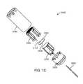
- a transducer subassembly 3000is placed at or near the distal portion of a catheter 2000 and contained within a tubular jacket 3400 .
- the catheter 2000may be any suitable catheter and comprises at least one lumen 2100 .
- the components of transducer subassembly 3000are shown in an assembled view in FIG. 1B , and in an exploded view in FIG. 1C .
- the transducer subassembly 3000comprises a transducer element 3100 having a distal face 3102 and a proximal face 3104 .
- the transducer subassembly 3000further comprises heat sinks that serve to cool the transducer element 3000 by conducting heat away from it.
- the transducer subassembly 3000comprises a distal heat sink 3300 bonded to the distal face 3102 of the transducer element 3100 , and a proximal heat sink 3200 bonded to the proximal face 3104 of the transducer element 3100 .
- the heat sinksare further configured to increase the operating efficiency of the transducer element 3000 through acoustic matching and acoustic reflection.
- the distal heat sink 3300comprises an acoustically matching layer portion, i.e., a portion whose composition and thickness provides a 1 ⁇ 4 wavelength matching layer between the transducer element 3100 and any fluid in front of the transducer subassembly 3000 .
- the proximal heat sink 3200comprises an acoustically mismatched layer portion, i.e., a portion whose composition is acoustically mismatched to the acoustic impedance of the transducer element 3100 , thereby reflecting ultrasound waves emanating from the transducer element 3100 back towards the transducer element 3100 .
- acoustically mismatched layer portioni.e., a portion whose composition is acoustically mismatched to the acoustic impedance of the transducer element 3100 , thereby reflecting ultrasound waves emanating from the transducer element 3100 back towards the transducer element 3100 .
- the transducer subassembly 3000also comprises a base 3500 anchoring the heat sinks 3200 and 3300 , with the transducer element 3100 bonded between the heat sinks.
- the transducer subassembly 3000is powered using one or more electrical cables 3600 bonded to each of the heat sinks 3200 and 3300 . These electrical cables 3600 are exemplarily provided through a pair of twisted wires, as shown in FIGS. 1B and 1C . As will be appreciated, they could also be coaxial or separate untwisted wires.
- the heat sinks 3200 and 3300comprise electrical attachments (not shown) for electrically coupling the heat sinks 3200 and 3300 to the electrical cables 3600 , thereby providing electrical power to the transducer element 3100 .
- the transducer element 3100comprises electrode platings on the distal and proximal faces in order to distribute the electrical energy over the faces of the transducer element 3100 .
- the transducer element 3100comprises a single transducer element.
- the transduceris of a suitable size to fit into a catheter configured to be introduced percutaneously into the atria of the heart.
- the transducer diameteris less than 0.2 inches, and preferably less than 0.15 inches.
- the transducer elementmay comprise a variety of geometries, as well as a variety of acoustically active and inactive portions. Such transducer element properties in turn influence the transducer's imaging and ablative properties, such as the shape of the created ablation lesions.
- the transducer element 3100is a flat, circular disc that transmits ultrasound energy from its proximal and distal faces.
- the transducer element 3100may alternatively have more complex geometry, such as either concave or convex, to achieve an effect of a lens or to assist in apodization (i.e., in selectively decreasing the vibration of a portion or portions of the surfaces of the transducer element 3100 ) and management of the propagation of the ultrasound beam.
- the transducers 3100 a and 3100 binclude at least one acoustically inactive portion 4200 , with the remainder of the transducer surface comprising an acoustically active portion.
- the acoustically inactive portion 4200does not emit an energy beam when the transducer is energized, or may alternatively emit an energy beam with a very low (substantially zero) energy.
- the acoustically inactive portion 4200has several functions.
- the shape of a lesion produced by ablating tissue using such a transducermay correspond with the shape of the acoustically active ablating portions.
- the shape of the lesionwill be tear-drop shaped.
- the shape of the lesionwill be approximately tooth-shaped or a blunted tear-shaped. This is because the acoustically inactive portion 4200 in FIG. 2A will preclude prolonged ablation at the corresponding central portion of the tissue. Since prolonged ablation of tissue creates a deeper ablation, the presence of acoustically inactive portion 4200 precludes ablation from reaching further into the tissue at the central portion.
- the lesionthus is approximately tooth-shaped or blunted tear-shaped, as illustrated by the exemplary lesion shape L of FIG. 2A , rather than tear-shaped.
- acoustically inactive portion 4200in any of the embodiments shown, further functions to aid in the temperature regulation of the transducer elements 3100 a and 3100 b , i.e., in preventing the transducer elements from becoming too hot.
- an acoustically inactive portion 4200is a hole or gap defined by the boundary of the acoustically active region of the transducer element.
- an optional coolant sourcemay be coupled to (or in the case of a coolant fluid, it may flow through) the hole or gap defined by the transducer element to further cool and regulate the temperature of the transducer element.
- the acoustically inactive portion 4200may comprise a material composition with different properties from that of the active region of the transducer element.
- the acoustically inactive materialmay be made of a metal, such as copper, which further functions to draw or conduct heat away from the transducer element.
- the acoustically inactive portion 4200may be made from the same material as the transducer element, but with the electrode plating removed or disconnected from the electrical attachments.
- the acoustically inactive portion 4200may be disposed along the full thickness of the transducer element, or may alternatively be a layer of material on or within the transducer element that has a thickness less than the full thickness of the transducer element.
- the transducer element 3100 ais a doughnut-shaped transducer that comprises a hole (or acoustically inactive portion) 4200 in the center portion of the otherwise circular disc-shaped transducer element.
- the transducer element 3100 a of this embodimenthas a circular geometry, but may alternatively be elliptical, polygonal as shown in FIG. 2B , or any other suitable shape.
- the transducer element 3100 aincludes a singular, circular acoustically inactive portion 4200 , but may alternatively include any suitable number of acoustically inactive portions 4200 of any suitable geometry, as shown in FIG. 2B .
- Exemplary geometries of acoustically inactive portionsinclude circular, square, rectangular, elliptical, polygon, or any other shaped region.
- the total energy emitted from the transducer elementis related to the acoustically active surface area of the transducer element. Therefore, the size and location of acoustically inactive portion(s) 4200 may sufficiently reduce the heat build-up in the transducer element, while allowing the transducer element to provide as much output energy as possible or as desired.
- the transducer elementsmay optionally be configured to operate at more than one frequency. This allows them to be used for multi-frequency ablating or for contemporaneous ablation and diagnosis.
- a multi-frequency transducer elementmay be operated intermittently at a first power level using a first frequency range that is used to image a portion of the tissue in order to identify a target tissue, and operated at a second power level using a second frequency range that is used to ablate the target tissue.
- the imaging frequencyis in the range of about 5 MHz to 30 MHz
- the ablation frequencyis preferably in the range of 5 to 25 MHz, more preferably in the range 8 to 20 MHz, and even more preferably in the range 10 to 18 MHz.
- the transducers achieving these configurationsare shown to exemplarily be annular transducers or grid arrays.
- the transducer elements 3100 c and 3100 dare configured to be capable of transmitting at more than one frequency.
- the transducer element 3100 cincludes a plurality of annular transducer portions 4400 .
- the plurality of annular transducer portionsis a plurality of concentric rings, but may alternatively have any suitable configuration with any suitable geometry, such as elliptical or polygonal.
- the transducer element 3100 cincludes one or more acoustically inactive portions 4200 , such as the center portion of the transducer 3100 c .
- the plurality of annular transducer portions 4400includes at least a first annular portion and a second annular portion.
- the first annular portionmay have material properties that differ from those of the second annular portion, such that the first annular portion emits a first energy beam that is different from a second energy beam emitted by the second annular portion.
- the first annular portionmay be energized with a different frequency, voltage, duty cycle, power, and/or for a different length of time from the second annular portion.
- the first annular portionmay be operated in a different mode from the second annular portion.
- the first annular portionmay be operated in a therapy mode, such as ablation mode, which delivers a pulse of ultrasound energy sufficient for heating the tissue.
- the second annular portionmay be operated in an imaging mode, such as A-mode, which delivers a pulse of ultrasound of short duration, which is generally not sufficient for heating of the tissue but functions to detect characteristics of the target tissue and/or environment in and around the ultrasound delivery system.
- A-modean imaging mode
- the first annular portionmay further include a separate electrical attachment from that of the second annular portion.
- the transducer element 3100 dincludes a grid of transducer portions 4600 .
- the grid of transducer portions 4600has any suitable geometry such as circular, rectangular, elliptical, polygonal, or any other suitable geometry.
- the transducer element 3100 d in this variationmay further include one or more transducer portions that are acoustically inactive.
- the grid of transducer portions 4600includes at least a first transducer portion and a second transducer portion. The first transducer portion and the second transducer portion are portions of a single transducer with a single set of material properties.
- the first transducer portionis energized with a different frequency, voltage, duty cycle, power, and/or for a different length of time from the second transducer portion. Furthermore, the first transducer portion may be operated in a different mode from the second transducer portion. For example, similar to the description above, the first transducer portion may operate in a therapy mode, such as ablate mode, while the second transducer portion may operate in a imaging mode, such as A-mode.
- the first transducer portionmay further include a separate electrical attachment from that of the second transducer portion. For example, the first transducer portion may be located towards the center of the transducer element 3100 d and the second transducer portion may be located towards the outer portion of the transducer element 3100 d .
- the second transducer portionmay be energized while the first transducer portion remains inactive.
- the first transducer portionhas material properties that differ from those of the second transducer portion, such that the first transducer portion emits a first energy beam that is different from a second energy beam emitted from the second transducer portion.
- the first transducer portionmay also be energized with a different frequency, voltage, duty cycle, power, and/or for a different length of time from the second transducer portion.
- FIG. 3shows the proximal heat sink 3200 .
- the proximal heat sink 3200comprises a bonding portion 3210 and a substantially bent portion forming legs 3220 that are generally orthogonal to the bonding portion 3210 .
- the proximal heat sinkfurther comprises at least one electrical attachment 3230 .
- the distal heat sinkcomprises an electrical attachment 3330 (shown in FIG. 4 ).
- the electrical wires 3600are connected to the electrical attachments 3230 and 3330 .
- the disclosed arrangementeliminates “hot spots” and results in a uniform electrical power density across the surface of the crystal. Additionally, this results in an easier assembly or manufacturing process.
- the bonding portion 3210is bonded to the proximal face of the transducer element 3100 with a suitable bonding material such as an epoxy to form a bond layer. Though shown as substantially flat in this embodiment, one skilled in the art will appreciate that the bonding portion 3210 may be any suitable configuration such as a concave portion to still maintain the functionality described herein.
- the substantially bent portion 3220comprises legs, or elements that protrude proximally from the transducer element 3100 . Further, the bent portion 3220 is configured in a manner to allow for fluid to flow through the bent portion and also allows the fluid to surround and cool the proximal face of the transducer element 3100 .
- the fluid that could be accommodated within the bent portioncould be any suitable fluid that achieves an appropriate balance between having an effective heat sink and minimizing acoustic reverberations that degrade image performance.
- the proximal heat sink 3200is formed from a suitable material such as copper of a suitable thickness. The thickness of the material for this heat sink preferably ranges between 0.0001 inches to 0.01 inches for a copper heat sink.
- Proximal heat sink 3200serves to cool the proximal face of the transducer by conducting and dissipating the heat away from the transducer element 3100 .
- Heat from the transducer element 3100is absorbed by the bonding portion 3210 , and conducted to the bent portion 3220 where it is dissipated into the circulating fluid. This dissipation provides some cooling to the proximal face of the transducer element 3100 .
- the bent portion 3220is configured in a manner to allow for fluid to surround and cool the proximal face of the transducer element 3100 . For example, as shown in FIG.
- the bent portion 3220provides for one or more pockets behind the transducer element 3100 where a fluid may be introduced to flow and cool both the transducer element 3100 as well as the proximal heat sink 3200 that has dissipated heat from the proximal face of the transducer element 3100 .
- the proximal heat sink 3200also serves as a heat spreader to reduce hot spots in the transducer element 3100 , and thereby preserve it over its entire face. Without this heat spreading, the center of the transducer element 3100 would be substantially hotter than the rest of the transducer element 3100 .
- the bonding portion 3210can be configured to maximize the amount of reflected energy transmitted from the transducer element 3100 . Since many metals suitable for heat sink applications have acoustic impedances that are not too dissimilar from PZT, the boundary between PZT and the heat sink itself does not provide a very effective reflective interface. However, another material immediately proximal to the heat shield could be selected so that it provides an efficient acoustic reflector. For example, air provides an excellent acoustic mismatch, as does water, and therefore acts as good reflectors. Water is preferred since it also acts as a thermal conductor, even though it is not quite as effective a reflector as air. Air could be used, provided that it does not interfere with the flow of cooling fluid around the transducer assembly.
- the bonding portion of 3210could be constructed from two metal layers capturing a third thin layer of air in between.
- a backing materialmay be located proximal to the proximal heat sink 3200 to provide an acoustically absorptive medium to minimize reverberations to further optimize imaging performance.
- Such backing materialsmay optionally be made of combinations of epoxy, metal particles, tungsten and the like.
- the transducer element 3100 or the transducer subassembly 3000may be placed on a tripod-style structure (not shown) such that the proximal surface of the transducer element 3100 faces into the tripod.
- a pocketforms in the space between the transducer element 3100 and the tripod base.
- This pocketserves as an alternative backing with the same two-fold purpose. First, it is acoustically mismatched and thereby reflective of the ultrasound waves emanating from the transducer element 3100 . Second, as fluid (for example saline or water) is introduced into the transducer assembly 3000 , the pocket also allows for the fluid to come into contact with the transducer element 3100 and thereby provide for additional cooling.
- fluidfor example saline or water
- acoustically mismatched materialwith reasonable thermal conduction could be used in place of fluid.
- materialsinclude metal with trapped air, for example steel wool or porous metal with entrapped air.
- the rear of the PZTmay comprise a thin heat spreader comprising the entire rear face with a pocket of porous metal attached behind.
- the center of the PZTcould be further cooled by providing a thermally conducting center post as part of the heat sink, allowing an annular ring of air to be trapped behind the bonding portion 3210 .
- a distal heat sink 3300(which also serves as a heat spreader) for distributing the heat and cooling the distal face of the transducer element 3100 .
- the distal heat sink 3300also comprises a bonding portion 3310 and a substantially bent portion 3320 that is orthogonal to the flat portion 3310 .
- the distal heat sinkfurther comprises at least one electrical attachment 3330 .
- the distal heat sink 3300is configured such that the bonding portion 3310 is bonded to the distal face of the transducer element 3100 .
- the substantially bent portion 3320comprises elements or legs that protrude proximally from the transducer element 3100 .
- the bonding portion 3310is further configured to serve as an acoustically matching layer for the transducer element 3100 .
- the bonding portion 3310is made of a suitable material such as aluminum; other such suitable materials include graphite, metal-filled graphite or ceramic, or an amalgam of graphite and copper or tungsten, in suitable thickness that range from 0.026 inches to 0.00026 inches so that it is 1 ⁇ 4 wavelength at the desired frequency.
- the bonding portion 3310is bonded to the distal face of the transducer element 3100 with a suitable bonding material such as an epoxy to form a bond layer.
- the bonding portion 3310comprises perforations or holes 3315 that may be filled with epoxy applied in a layer of a suitable thinness to enhance the acoustic impedance matching.
- Perforations in the distal matching layercan be accomplished in many ways.
- the perforated structureis made of a combination of metal matrix containing open spaces, later to be filled with an epoxy material.
- the metal matrixcan be a wire grid.
- the perforated structuremay be a matrix of epoxy film, and the holes may be filled with a metal such as aluminum.
- the ratio of epoxy to the metal mixtureis configured to enhance acoustic impedance matching.
- the acoustic impedanceis determined by the acoustic impedance of the two composite materials, and the ratio of the mixture. For example, using aluminum and EPO-TEK® 377 (Epoxy Technology, Inc., Billerica, Mass.) the appropriate ratio is 35-60% volume fraction of epoxy and a good acoustic impedance matching is achieved at a 40-50% volume fraction of epoxy and an ideal match about 41%. Additionally, the perforations or holes 3315 have a sufficiently small diameter as compared to the wavelength of the ultrasonic beam, thereby allowing the bonding portion 3310 to appear homogeneous to the propagating waves emanating from the transducer element 3100 .
- the bonding portion 3210 at proximal surface of the transducer crystalalso may benefit from using perforations or holes in the material used to achieve acoustic impedance mismatch.
- Such materialsmay include copper, tungsten and the like.
- an epoxy layer with metal particles sprinkled in it and a distribution of holes or perforationsmay achieve the same purpose of providing acoustic impedance mismatch.
- both non-conductive and conductive epoxycould be used to form either the proximal or distal bond layer.
- the epoxyis exemplarily a non-conductive epoxy of a low viscosity (e.g., EPO-TEK® 377).
- the epoxyis applied in a layer of suitable thinness to minimize its impact on acoustic impedance matching, while maximizing thermal conduction to cool the transducer 3100 .
- the bond layersare also configured to electrically connect the heat sinks 3310 and 3210 to the transducer 3100 . This is successfully accomplished without the use of conductive epoxy by configuring the transducer 3100 faces and the bonding portions 3310 and 3210 to be rough.
- each bond layeris of sufficient thinness to allow the surface roughness of the transducer 3100 to electrically contact the surface roughness of the heat sinks 3310 and 3210 . This allows the rough surfaces of the transducer element 3100 to come into direct electrical contact with their relevant heat sinks, thereby obviating the need for using electrically conductive epoxy (which may degrade with heat). Thus, electrical conduction occurs via the contact points between the rough surfaces of the transducer element 3100 and the heat sinks, rather than through the epoxy.
- parylene or any such suitable coatingis disposed on the bonding portion 3310 of the distal heat sink 3300 to act as an additional matching layer.
- One result of the coatingmay be to thus produce a second acoustic matching layer for increased efficiency of transducer element 3100 conduction and to further optimize the wide bandwidth performance.
- the thickness of this parylene coatis 1 ⁇ 4 of the target ultrasound wavelength.
- both heat sinks 3200 and 3300are coated with parylene or any such suitable coatings to provide electrical isolation. Further, heat sinks are anodized to provide electrical isolation while maximizing thermal conduction.
- the transducer subassembly 3000is located within a tubular jacket 3400 , as shown in FIG. 5 .
- the tubular jacket 3400is a hollow cylinder with a proximal and distal end.
- the transducer subassembly 3000is placed into the tubular jacket 3400 such that the distal end of the tubular jacket protrudes a suitable distance, for example between 1 mm to 5 mm beyond the distal end of the transducer subassembly 3000 .
- the distal end of the tubular jacket 3400comprises a distal opening 3410 , and fluid exit ports 3420 located near the distal opening. Cooling of the transducer element 3100 may be accomplished by introducing a cooling fluid or gel, such as saline, water, or any physiologically compatible fluid or gel, into the proximal end of the tubular jacket 3400 .
- the cooling fluidhas a lower temperature relative to the temperature of the transducer element 3100 .
- the cooling fluidflows along the bent portions 3220 and 3320 of heat sinks 3200 and 3300 and over both bonding portions 3210 and 3310 and exits through the distal opening 3410 , the fluid exit ports 3420 , or any combination thereof.
- the exit ports 3420may be in the form of a grating, a screen, holes, drip holes, a weeping structure, or any of a number of suitable apertures.
- any or all of the metal components described in transducer subassembly 3000are provided with a plating of a suitable biocompatible material such as gold. Such plating is provided to the individual components before the transducer assembly is assembled.
- the temperature of the cooling fluid or gelis sufficiently low that it cools the transducer element 3100 and, optionally, the target tissue.
- the temperature of the fluid or gelis between approximately ⁇ 5 and body temperature.
- the temperature of the cooling fluid or gelis within a temperature range such that it cools the transducer element 3100 , but does not cool the target tissue, and may actually warm the target tissue.
- the fluid or gelmay alternatively be any suitable temperature, including room temperature, to sufficiently cool the transducer element 3100 .
- the invention described abovehas the advantage of keeping the smaller transducer assembly cool.
- the transducer diameteris small enough (less than 0.2 inches, and ideally less than 0.15 inches) to fit into the tip of a catheter and yet generate power density levels that are high enough to create tissue lesions (about 50 watts/cm 2 to 2500 watts/cm 2 ).
- This inventionkeeps the transducer assembly cool in order to create tissue lesions efficiently.
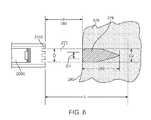
- the interaction of the ultrasound beam with the tissueis shown in FIG. 6 .
- the tissue 276is presented to the ultrasound beam 272 within a collimated length L.
- the front surface 280 of the tissue 276is at a distance d ( 282 ) away from the distal tip 2110 of the catheter 2000 .
- d282
- the ultrasound beam 272travels through the tissue 276 , its energy is absorbed and scattered by the tissue 276 , and most of the ultrasound energy is converted to thermal energy. This thermal energy heats the tissue to temperatures higher than the surrounding tissue.
- the resultis a heated zone 278 which has a typical shape of an elongated tear drop.
- the diameter D 1 of the zone 278is smaller than the transducer aperture diameter D at the tissue surface 280 , and further, the outer layer(s) of tissue 276 remain substantially undamaged. This is due to the thermal cooling provided by the surrounding fluid which is flowing past the tissue surface 280 . More or less of the outer layers of tissue 276 may be spared or may remain substantially undamaged, depending on the amount that the tissue surface 280 is cooled and/or depending on the characteristics of the ultrasound delivery system (including the transducer element 3100 the ultrasound beam 272 , the ultrasound energy and the frequency). The energy deposited in the ablation zone 278 interacts with the tissue such that the endocardial surface remains pristine and/or not charred.
- the ablation zone 278has a larger diameter D 2 than D 1 , as determined by the heat transfer characteristics of the surrounding tissue as well as the continued input of the ultrasound energy from the beam 272 .
- the ultrasound energyis being absorbed by the tissue 276 , and less of it is available to travel further into the tissue.
- a correspondingly smaller diameter heated zoneis developed in the tissue 276 , and the overall result is the formation of the heated ablation zone 278 which is in the shape of an elongated tear drop limited to a depth 288 into the tissue 276 .
- the formation of the ablation zone(including the size of the ablation zone and other characteristics) is dependent on time, as shown in FIGS. 7A-7D , which show the formation of the lesion at times t 1 , t 2 , t 3 and t 4 , respectively.
- FIGS. 7A-7Dshow the formation of the lesion at times t 1 , t 2 , t 3 and t 4 , respectively.
- the ablation lesion 278grows slightly in diameter and length, and then stops growing due to the steady state achieved in the energy transfer from its ultrasound form to the thermal form balanced by the dissipation of the thermal energy into the surrounding tissue.
- the example shown in of FIG. 7Dshows the lesion after an exposure t 4 of approximately 30 seconds to the ultrasound beam 272 .
- the lesionreaches a natural limit in size and does not grow indefinitely.
- the shape of the lesion or ablation zone 278 formed by the ultrasound beam 272depends on factors such as the ultrasound beam 272 , the transducer element 3100 (including the material, the geometry, the portions of the transducer element 3100 that are energized and/or not energized, etc.), any matching layers and/or backings present, the electrical signal from the source of electrical energy (including the frequency, the voltage, the duty cycle, the length and shape of the signal, etc.), and the duration of energy delivery.
- the characteristics of the target tissueinclude the thermal transfer properties and the ultrasound absorption, attenuation, and backscatter properties of the target tissue and surrounding tissue.
- the size and characteristics of the ablation zone 278also depend on the frequency and voltage applied to the transducer element 3100 to create the desired ultrasound beam.
- the particular example lesion shown in FIGS. 7A through 7Dis a tear-shaped lesion, for example as produced by a transducer element 3100 comprising a circular disc.
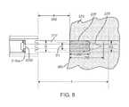
- a second variation of ablation shapeis shown in FIG. 8 , where the ablation zone 278 ′ has a shorter depth 288 ′. In this variation, the lesion 278 ′ has a more blunt shape than the ablation zone 278 of FIG. 6 .
- One possible lesion geometry of this second variationmay be a tooth-shaped geometry, as shown in FIG.
- zone 278 ′(similarly to zone 278 in FIG. 6 ) has a diameter D 1 smaller than the diameter D of the beam 272 ′ at the tissue surface 280 due to the thermal cooling provided by the surrounding fluid flowing past the tissue surface 280 .
- This variation in lesion geometryis produced by a transducer 3100 a having an acoustically inactive portion 4200 located at its center, i.e., a doughnut-shaped transducer which emits an ultrasound beam 272 ′ that is generally more diffused, with a broader, flatter profile, than the ultrasound beam 272 shown in FIG. 6 .
- the ultrasound energy densitydetermines the speed at which the ablation occurs.
- the acoustic power delivered by the transducer element 3100divided by the cross sectional area of the beamwidth, determines the energy density per unit time.
- effective acoustic powerranges preferably from 0.5 to 25 watts, more preferably from 2 to 10 watts, and even more preferably from 2 to 7 watts.
- the corresponding power densitiesrange from approximately 50 watts/cm 2 to 2500 watts/cm 2 ). These power densities are developed in the ablation zone. As the beam diverges beyond the ablation zone, the energy density falls such that ablation will not occur, regardless of exposure time.
- the transducer subassembly 3000may additionally be coupled to a sensor (not shown).
- a sensoris a temperature sensor.
- the temperature sensorfunctions to detect the temperature of the surrounding environment, the transducer element 3100 , and/or the temperature of any other suitable element or area.
- the sensormay also be used to monitor temperature of cooling fluid as it flows past the transducer.
- the temperature sensoris a thermocouple, but may alternatively be any suitable temperature sensor, such as a thermistor or an infrared temperature sensor.
- the temperature sensoris coupled to the transducer, for example, on the proximal face.
- Temperature information gathered by the sensoris used to manage the delivery of continuous ablation energy to the tissue 276 during therapy, as well as to manage the temperature of the target tissue and/or the ultrasound delivery system.
- the sensorhas a geometry that is substantially identical to the geometry of the transducer element 3100 , so that the area diagnosed by the sensor is substantially identical to the area to be treated by the transducer element 3100 .
- the sensorhas a smaller geometry to minimize interfering with the delivery of ultrasound energy, but may be located in a region that is a local hot spot.
- a small thermocouple mounted in the center of the proximal heat spreader 3200monitors the temperature at the hottest spot of the transducer assembly. Additional details on temperature sensors are disclosed in applications previously incorporated by reference above.
- the same ultrasound transducer element 3100serves as a sensor and is used for the purpose of tissue detection.
- the transducer element 3100in order to achieve ablation, is used to generate and deliver an ultrasound beam of sufficient energy to the tissue in a manner such that the energy input exceeds the thermal relaxation provided by the cooling due to the surrounding tissue.
- This mode of energizing the ultrasound transducer element 3100is termed as the ablation mode.
- the transducer element 3100may be used to image tissue or to detect tissue characteristics, by utilizing an ultrasound signal optimized for tissue sensing which is generally not sufficient for heating of the tissue.
- A-Modeor Amplitude Mode imaging.
- This mode of energizing the transducer element 3100is termed as the imaging mode.
- the imaging modeis utilized in directing the therapy provided by the ablation of the tissue.
- the transducer element 3100can be used in the imaging mode in order to detect the gap (namely, the distance of the tissue surface from the distal tip of the catheter 2000 ), the thickness of the tissue targeted for ablation, characteristics of the ablated tissue, the incident beam angle, or any other suitable parameter or characteristic of the tissue and/or the environment around the ultrasound delivery system, such as temperature, thickness and ablation depth. Additional details on these and other applicable features are described in the disclosures previously incorporated by reference.
- the ultrasound delivery system of the preferred embodimentsincludes a processor, coupled to the sensor, that controls the electrical attachments and/or the electrical signal delivered to the electrical attachments, based on the information obtained by the sensor.
- the processormay be a conventional processor, or it may alternatively be any suitable device to perform the desired processing functions.
- the processorreceives information from the sensor, such as information related to the distance between the catheter and the tissue (i.e., the gap distance), the thickness of the tissue targeted for ablation, the characteristics of the ablated tissue, or any other suitable parameter or characteristic. Based on this information, the processor controls the ultrasound beam emitted by the transducer element 3100 by modifying the electrical signal sent to the transducer element 3100 via the electrical attachment. This may include modifying the frequency, the voltage, the duty cycle, the length of the pulse, and/or any other suitable parameter. The processor may also control the ultrasound beam in multi-element transducers by controlling which portions of the transducer element are energized, and/or by controlling the frequency, voltage, duty cycle, etc. at which various portions of the transducer element may be energized.
- the processormay further be coupled to a fluid flow controller.
- the processormay control the fluid flow controller in order to increase or decrease fluid flow based on the detected characteristics of the ablated tissue, of the unablated or target tissue, the temperature of the cooling fluid, tissue and/or energy source, and/or any other suitable conditions. Further, the processor may control the fluid flow controller in order to maintain the transducer element 3100 within a desired operating range of temperatures. Further, the motion of the transducer to create a lesion line or shape in the tissue may be controlled either by an operator or via one or more motors under processor control.
- the shape of the ablation zone 278can be controlled.
- the depth 288 of the ablation zonecan be controlled such that a transmural or substantially transmural lesion is achieved.
- the nature of the lesioncan be controlled by controlling the speed of the beam. The speed at which the beam moves along the tissue determines the amount of energy deposited in the tissue. Thus, for example, slower speeds result in longer dwell times, thereby increasing the energy transferred to the tissue and, hence, creating deeper lesions.
- the processorfunctions to minimize the possibility of creating a lesion beyond the targeted tissue, for example, beyond the outer atrial wall.
- the processorturns off the power generator and/or ceases to send electrical signals to the transducer and/or moves the beam.
- the processormay function to maintain a preferred gap distance between the transducer and the surface of the target tissue.
- the gap distanceis preferably between 2 mm and 25 mm, more preferably between 2 mm and 20 mm, and even more preferably between 2 mm and 15 mm.
- the processormay reposition the energy delivery system. For example, as the catheter 2000 is rotated, the ablation window sweeps an ablation path (such as a circular or elliptical ablation path) creating a section of a conical shell.
- the processormay move the elongate member forwards or backwards along the Z-axis, or indicate that it should be moved, in order to adjust for possible variations in anatomy.
- the operatorcan reposition the catheter 2000 , or the processor may be coupled to a motor drive unit or other control unit that functions to position the catheter 2000 .
- transducer elements and transducer subassemblieshave been described in the context of ablation catheters, it should be understood that the transducer elements and transducer subassemblies described herein can be used as part of any device configured to ultrasonically image and/or ablate tissue. Additionally, while the above is a complete description of the preferred embodiments of the invention, various alternatives, modifications, and equivalents may be used. Therefore, the above description should not be taken as limiting the scope of the invention which is defined by the appended claims.
Landscapes
- Health & Medical Sciences (AREA)
- Life Sciences & Earth Sciences (AREA)
- Public Health (AREA)
- Nuclear Medicine, Radiotherapy & Molecular Imaging (AREA)
- Radiology & Medical Imaging (AREA)
- Biomedical Technology (AREA)
- Animal Behavior & Ethology (AREA)
- General Health & Medical Sciences (AREA)
- Engineering & Computer Science (AREA)
- Veterinary Medicine (AREA)
- Biophysics (AREA)
- Physics & Mathematics (AREA)
- Pathology (AREA)
- Heart & Thoracic Surgery (AREA)
- Medical Informatics (AREA)
- Molecular Biology (AREA)
- Surgery (AREA)
- Gynecology & Obstetrics (AREA)
- Surgical Instruments (AREA)
Abstract
Description
Claims (31)
Priority Applications (3)
| Application Number | Priority Date | Filing Date | Title |
|---|---|---|---|
| US12/620,287US8475379B2 (en) | 2008-11-17 | 2009-11-17 | Systems and methods for ablating body tissue |
| US13/907,412US9737323B2 (en) | 2008-11-17 | 2013-05-31 | Systems and methods for imaging and ablating body tissue |
| US15/669,675US10154831B2 (en) | 2008-11-17 | 2017-08-04 | Methods for imaging and ablating body tissue |
Applications Claiming Priority (4)
| Application Number | Priority Date | Filing Date | Title |
|---|---|---|---|
| US11540308P | 2008-11-17 | 2008-11-17 | |
| US14880909P | 2009-01-30 | 2009-01-30 | |
| US25499709P | 2009-10-26 | 2009-10-26 | |
| US12/620,287US8475379B2 (en) | 2008-11-17 | 2009-11-17 | Systems and methods for ablating body tissue |
Related Child Applications (1)
| Application Number | Title | Priority Date | Filing Date |
|---|---|---|---|
| US13/907,412ContinuationUS9737323B2 (en) | 2008-11-17 | 2013-05-31 | Systems and methods for imaging and ablating body tissue |
Publications (2)
| Publication Number | Publication Date |
|---|---|
| US20100125198A1 US20100125198A1 (en) | 2010-05-20 |
| US8475379B2true US8475379B2 (en) | 2013-07-02 |
Family
ID=42172559
Family Applications (1)
| Application Number | Title | Priority Date | Filing Date |
|---|---|---|---|
| US12/620,287Expired - Fee RelatedUS8475379B2 (en) | 2008-11-17 | 2009-11-17 | Systems and methods for ablating body tissue |
Country Status (1)
| Country | Link |
|---|---|
| US (1) | US8475379B2 (en) |
Cited By (2)
| Publication number | Priority date | Publication date | Assignee | Title |
|---|---|---|---|---|
| WO2017079510A1 (en) | 2015-11-04 | 2017-05-11 | Vytronus, Inc. | Systems and methods for imaging and ablating tissue |
| US11135455B2 (en) | 2016-04-15 | 2021-10-05 | Carthera | Ultrasonic thermal ablation probe |
Families Citing this family (27)
| Publication number | Priority date | Publication date | Assignee | Title |
|---|---|---|---|---|
| US8241274B2 (en) | 2000-01-19 | 2012-08-14 | Medtronic, Inc. | Method for guiding a medical device |
| US8150519B2 (en) | 2002-04-08 | 2012-04-03 | Ardian, Inc. | Methods and apparatus for bilateral renal neuromodulation |
| US7617005B2 (en) | 2002-04-08 | 2009-11-10 | Ardian, Inc. | Methods and apparatus for thermally-induced renal neuromodulation |
| US20040082859A1 (en) | 2002-07-01 | 2004-04-29 | Alan Schaer | Method and apparatus employing ultrasound energy to treat body sphincters |
| EP2540246B8 (en)* | 2006-05-12 | 2020-10-07 | Vytronus, Inc. | Device for ablating body tissue |
| US10499937B2 (en) | 2006-05-19 | 2019-12-10 | Recor Medical, Inc. | Ablation device with optimized input power profile and method of using the same |
| US20080039746A1 (en) | 2006-05-25 | 2008-02-14 | Medtronic, Inc. | Methods of using high intensity focused ultrasound to form an ablated tissue area containing a plurality of lesions |
| AU2009313687B2 (en) | 2008-11-17 | 2015-11-26 | Vytronus, Inc. | Systems and methods for ablating body tissue |
| KR101673574B1 (en) | 2009-10-30 | 2016-11-07 | 레코 메디컬, 인코포레이티드 | Method and apparatus for treatment of hypertension through percutaneous ultrasound renal denervation |
| US8382672B2 (en)* | 2010-03-12 | 2013-02-26 | Claire Andrews | Macro/micro duty cycle devices, systems, and methods employing low-frequency ultrasound or other cyclical pressure energies |
| WO2011161592A2 (en)* | 2010-06-22 | 2011-12-29 | Koninklijke Philips Electronics N.V. | System with interventional ultrasound monitoring device |
| US8585601B2 (en) | 2010-10-18 | 2013-11-19 | CardioSonic Ltd. | Ultrasound transducer |
| WO2012052925A1 (en) | 2010-10-18 | 2012-04-26 | CardioSonic Ltd. | An ultrasound transceiver and control of a thermal damage process |
| US9566456B2 (en)* | 2010-10-18 | 2017-02-14 | CardioSonic Ltd. | Ultrasound transceiver and cooling thereof |
| US9028417B2 (en) | 2010-10-18 | 2015-05-12 | CardioSonic Ltd. | Ultrasound emission element |
| US10357304B2 (en) | 2012-04-18 | 2019-07-23 | CardioSonic Ltd. | Tissue treatment |
| US11357447B2 (en) | 2012-05-31 | 2022-06-14 | Sonivie Ltd. | Method and/or apparatus for measuring renal denervation effectiveness |
| WO2014159276A1 (en) | 2013-03-14 | 2014-10-02 | Recor Medical, Inc. | Ultrasound-based neuromodulation system |
| EP2971232A1 (en) | 2013-03-14 | 2016-01-20 | ReCor Medical, Inc. | Methods of plating or coating ultrasound transducers |
| WO2014188430A2 (en) | 2013-05-23 | 2014-11-27 | CardioSonic Ltd. | Devices and methods for renal denervation and assessment thereof |
| KR20140144420A (en)* | 2013-06-11 | 2014-12-19 | 삼성전자주식회사 | Ultrasonic Probe and manufacturing method thereof |
| WO2015143440A1 (en)* | 2014-03-21 | 2015-09-24 | Sonocine, Inc. | System and method for performing an ultrasound scan of cellular tissue |
| JP6966324B2 (en) | 2015-04-10 | 2021-11-17 | コーニンクレッカ フィリップス エヌ ヴェKoninklijke Philips N.V. | Systems, methods and equipment for active thermal management of ultrasonic transducers |
| CN106037803B (en)* | 2016-06-27 | 2023-09-01 | 中国科学院苏州生物医学工程技术研究所 | Ultrasonic transducer array, ultrasonic interventional therapy system and ultrasonic ablation catheter |
| EP3541305B1 (en)* | 2016-11-16 | 2020-12-23 | Integra Lifesciences NR Ireland Limited | Ultrasonic surgical handpiece |
| WO2018173053A1 (en) | 2017-03-20 | 2018-09-27 | Sonievie Ltd. | Pulmonary hypertension treatment method and/or system |
| JP7145892B2 (en) | 2017-06-30 | 2022-10-03 | コーニンクレッカ フィリップス エヌ ヴェ | Intracavitary ultrasound imaging device having a substrate separated into a plurality of spaced apart segments, intracavitary ultrasound imaging device with grooves, and method of manufacture |
Citations (107)
| Publication number | Priority date | Publication date | Assignee | Title |
|---|---|---|---|---|
| US4641649A (en) | 1985-10-30 | 1987-02-10 | Rca Corporation | Method and apparatus for high frequency catheter ablation |
| US4757820A (en) | 1985-03-15 | 1988-07-19 | Kabushiki Kaisha Toshiba | Ultrasound therapy system |
| US5164920A (en)* | 1990-06-21 | 1992-11-17 | Siemens Aktiengesellschaft | Composite ultrasound transducer and method for manufacturing a structured component therefor of piezoelectric ceramic |
| US5246438A (en) | 1988-11-25 | 1993-09-21 | Sensor Electronics, Inc. | Method of radiofrequency ablation |
| US5295484A (en) | 1992-05-19 | 1994-03-22 | Arizona Board Of Regents For And On Behalf Of The University Of Arizona | Apparatus and method for intra-cardiac ablation of arrhythmias |
| US5314466A (en) | 1992-04-13 | 1994-05-24 | Ep Technologies, Inc. | Articulated unidirectional microwave antenna systems for cardiac ablation |
| US5405346A (en) | 1993-05-14 | 1995-04-11 | Fidus Medical Technology Corporation | Tunable microwave ablation catheter |
| US5471988A (en) | 1993-12-24 | 1995-12-05 | Olympus Optical Co., Ltd. | Ultrasonic diagnosis and therapy system in which focusing point of therapeutic ultrasonic wave is locked at predetermined position within observation ultrasonic scanning range |
| US5718241A (en) | 1995-06-07 | 1998-02-17 | Biosense, Inc. | Apparatus and method for treating cardiac arrhythmias with no discrete target |
| US5735811A (en) | 1995-11-30 | 1998-04-07 | Pharmasonics, Inc. | Apparatus and methods for ultrasonically enhanced fluid delivery |
| US5879314A (en) | 1997-06-30 | 1999-03-09 | Cybersonics, Inc. | Transducer assembly and method for coupling ultrasonic energy to a body for thrombolysis of vascular thrombi |
| US6012457A (en) | 1997-07-08 | 2000-01-11 | The Regents Of The University Of California | Device and method for forming a circumferential conduction block in a pulmonary vein |
| US6024740A (en) | 1997-07-08 | 2000-02-15 | The Regents Of The University Of California | Circumferential ablation device assembly |
| US6052576A (en) | 1996-07-09 | 2000-04-18 | Matra Communication | Radiocommunications equipment with a security calls mode, and extension unit forming part of such equipment |
| US6064902A (en) | 1998-04-16 | 2000-05-16 | C.R. Bard, Inc. | Pulmonary vein ablation catheter |
| US6117101A (en) | 1997-07-08 | 2000-09-12 | The Regents Of The University Of California | Circumferential ablation device assembly |
| US6161543A (en) | 1993-02-22 | 2000-12-19 | Epicor, Inc. | Methods of epicardial ablation for creating a lesion around the pulmonary veins |
| US6164283A (en) | 1997-07-08 | 2000-12-26 | The Regents Of The University Of California | Device and method for forming a circumferential conduction block in a pulmonary vein |
| US6237605B1 (en) | 1996-10-22 | 2001-05-29 | Epicor, Inc. | Methods of epicardial ablation |
| US6245095B1 (en) | 1998-03-24 | 2001-06-12 | Innercool Therapies, Inc. | Method and apparatus for location and temperature specific drug action such as thrombolysis |
| US6245064B1 (en) | 1997-07-08 | 2001-06-12 | Atrionix, Inc. | Circumferential ablation device assembly |
| US6251130B1 (en) | 1998-03-24 | 2001-06-26 | Innercool Therapies, Inc. | Device for applications of selective organ cooling |
| US6251129B1 (en) | 1998-03-24 | 2001-06-26 | Innercool Therapies, Inc. | Method for low temperature thrombolysis and low temperature thrombolytic agent with selective organ temperature control |
| US6261312B1 (en) | 1998-06-23 | 2001-07-17 | Innercool Therapies, Inc. | Inflatable catheter for selective organ heating and cooling and method of using the same |
| US6277116B1 (en) | 1994-05-06 | 2001-08-21 | Vidaderm | Systems and methods for shrinking collagen in the dermis |
| US6311090B1 (en) | 1995-05-05 | 2001-10-30 | Thermage, Inc. | Method and apparatus for controlled contraction of collagen tissue |
| US6311692B1 (en) | 1996-10-22 | 2001-11-06 | Epicor, Inc. | Apparatus and method for diagnosis and therapy of electrophysiological disease |
| DE10037660A1 (en) | 2000-07-31 | 2002-02-21 | Curative Ag | Ablation catheter for alveolar separation forms adjustable contact pattern treats auricular arrhythmia |
| US6379378B1 (en) | 2000-03-03 | 2002-04-30 | Innercool Therapies, Inc. | Lumen design for catheter |
| US6387089B1 (en) | 1995-09-15 | 2002-05-14 | Lumenis Ltd. | Method and apparatus for skin rejuvination and wrinkle smoothing |
| US20020087151A1 (en) | 2000-12-29 | 2002-07-04 | Afx, Inc. | Tissue ablation apparatus with a sliding ablation instrument and method |
| US6491039B1 (en) | 1998-01-23 | 2002-12-10 | Innercool Therapies, Inc. | Medical procedure |
| US6491716B2 (en) | 1998-03-24 | 2002-12-10 | Innercool Therapies, Inc. | Method and device for applications of selective organ cooling |
| US6500174B1 (en) | 1997-07-08 | 2002-12-31 | Atrionix, Inc. | Circumferential ablation device assembly and methods of use and manufacture providing an ablative circumferential band along an expandable member |
| US6500121B1 (en) | 1997-10-14 | 2002-12-31 | Guided Therapy Systems, Inc. | Imaging, therapy, and temperature monitoring ultrasonic system |
| US6514244B2 (en) | 1999-01-29 | 2003-02-04 | Candela Corporation | Dynamic cooling of tissue for radiation treatment |
| US6514249B1 (en) | 1997-07-08 | 2003-02-04 | Atrionix, Inc. | Positioning system and method for orienting an ablation element within a pulmonary vein ostium |
| US6517536B2 (en) | 2000-04-27 | 2003-02-11 | Atricure, Inc. | Transmural ablation device and method |
| US6529756B1 (en) | 1999-11-22 | 2003-03-04 | Scimed Life Systems, Inc. | Apparatus for mapping and coagulating soft tissue in or around body orifices |
| US6542781B1 (en) | 1999-11-22 | 2003-04-01 | Scimed Life Systems, Inc. | Loop structures for supporting diagnostic and therapeutic elements in contact with body tissue |
| US6547788B1 (en) | 1997-07-08 | 2003-04-15 | Atrionx, Inc. | Medical device with sensor cooperating with expandable member |
| US6551349B2 (en) | 1998-03-24 | 2003-04-22 | Innercool Therapies, Inc. | Selective organ cooling apparatus |
| US6585752B2 (en) | 1998-06-23 | 2003-07-01 | Innercool Therapies, Inc. | Fever regulation method and apparatus |
| US6592576B2 (en) | 2000-03-06 | 2003-07-15 | Plc Medical Systems, Inc. | Myocardial revascularization |
| US6595989B1 (en) | 1999-05-11 | 2003-07-22 | Atrionix, Inc. | Balloon anchor wire |
| US6599288B2 (en) | 2000-05-16 | 2003-07-29 | Atrionix, Inc. | Apparatus and method incorporating an ultrasound transducer onto a delivery member |
| US6602276B2 (en) | 1998-03-31 | 2003-08-05 | Innercool Therapies, Inc. | Method and device for performing cooling- or cryo-therapies for, e.g., angioplasty with reduced restenosis or pulmonary vein cell necrosis to inhibit atrial fibrillation |
| US6605084B2 (en) | 2000-03-24 | 2003-08-12 | Transurgical, Inc. | Apparatus and methods for intrabody thermal treatment |
| US6607527B1 (en) | 2000-10-17 | 2003-08-19 | Luis Antonio Ruiz | Method and apparatus for precision laser surgery |
| US6607502B1 (en) | 1998-11-25 | 2003-08-19 | Atrionix, Inc. | Apparatus and method incorporating an ultrasound transducer onto a delivery member |
| US6613046B1 (en) | 1999-11-22 | 2003-09-02 | Scimed Life Systems, Inc. | Loop structures for supporting diagnostic and therapeutic elements in contact with body tissue |
| US6635054B2 (en) | 2000-07-13 | 2003-10-21 | Transurgical, Inc. | Thermal treatment methods and apparatus with focused energy application |
| US6645199B1 (en) | 1999-11-22 | 2003-11-11 | Scimed Life Systems, Inc. | Loop structures for supporting diagnostic and therapeutic elements contact with body tissue and expandable push devices for use with same |
| US6645202B1 (en) | 1996-10-22 | 2003-11-11 | Epicor Medical, Inc. | Apparatus and method for ablating tissue |
| US6652515B1 (en) | 1997-07-08 | 2003-11-25 | Atrionix, Inc. | Tissue ablation device assembly and method for electrically isolating a pulmonary vein ostium from an atrial wall |
| US6652517B1 (en) | 2000-04-25 | 2003-11-25 | Uab Research Foundation | Ablation catheter, system, and method of use thereof |
| US6666858B2 (en) | 2001-04-12 | 2003-12-23 | Scimed Life Systems, Inc. | Cryo balloon for atrial ablation |
| US6666614B2 (en) | 2001-08-13 | 2003-12-23 | Weasler Engineering, Inc. | Automatic latching lockout shaft sensing coupler |
| US6669655B1 (en) | 1999-10-20 | 2003-12-30 | Transurgical, Inc. | Sonic element and catheter incorporating same |
| US6669687B1 (en) | 1999-06-25 | 2003-12-30 | Vahid Saadat | Apparatus and methods for treating tissue |
| US6676688B2 (en) | 1998-01-23 | 2004-01-13 | Innercool Therapies, Inc. | Method of making selective organ cooling catheter |
| US6676690B2 (en) | 1999-10-07 | 2004-01-13 | Innercool Therapies, Inc. | Inflatable heat transfer apparatus |
| US6685732B2 (en) | 1998-03-31 | 2004-02-03 | Innercool Therapies, Inc. | Method and device for performing cooling- or cryo-therapies for, e.g., angioplasty with reduced restenosis or pulmonary vein cell necrosis to inhibit atrial fibrillation employing microporous balloon |
| US6689128B2 (en) | 1996-10-22 | 2004-02-10 | Epicor Medical, Inc. | Methods and devices for ablation |
| US6692488B2 (en) | 1998-01-23 | 2004-02-17 | Innercool Therapies, Inc. | Apparatus for cell necrosis |
| US6702842B2 (en) | 1998-01-23 | 2004-03-09 | Innercool Therapies, Inc. | Selective organ cooling apparatus and method |
| US6711444B2 (en) | 1999-11-22 | 2004-03-23 | Scimed Life Systems, Inc. | Methods of deploying helical diagnostic and therapeutic element supporting structures within the body |
| US6745080B2 (en) | 1999-11-22 | 2004-06-01 | Scimed Life Systems, Inc. | Helical and pre-oriented loop structures for supporting diagnostic and therapeutic elements in contact with body tissue |
| US6752805B2 (en) | 2000-06-13 | 2004-06-22 | Atrionix, Inc. | Surgical ablation probe for forming a circumferential lesion |
| US6763722B2 (en) | 2001-07-13 | 2004-07-20 | Transurgical, Inc. | Ultrasonic transducers |
| US6780183B2 (en) | 2002-09-16 | 2004-08-24 | Biosense Webster, Inc. | Ablation catheter having shape-changing balloon |
| US6805128B1 (en) | 1996-10-22 | 2004-10-19 | Epicor Medical, Inc. | Apparatus and method for ablating tissue |
| US6814733B2 (en) | 2002-01-31 | 2004-11-09 | Biosense, Inc. | Radio frequency pulmonary vein isolation |
| US6840936B2 (en) | 1996-10-22 | 2005-01-11 | Epicor Medical, Inc. | Methods and devices for ablation |
| US20050049582A1 (en) | 2001-12-12 | 2005-03-03 | Debenedictis Leonard C. | Method and apparatus for fractional photo therapy of skin |
| US6869431B2 (en) | 1997-07-08 | 2005-03-22 | Atrionix, Inc. | Medical device with sensor cooperating with expandable member |
| US6889694B2 (en) | 2000-04-27 | 2005-05-10 | Atricure Inc. | Transmural ablation device |
| US6899711B2 (en) | 1999-04-05 | 2005-05-31 | Medtronic, Inc. | Ablation catheter and method for isolating a pulmonary vein |
| US6905509B2 (en) | 1998-01-23 | 2005-06-14 | Innercool Therapies, Inc. | Selective organ cooling catheter with guidewire apparatus and temperature-monitoring device |
| US6905494B2 (en) | 1998-03-31 | 2005-06-14 | Innercool Therapies, Inc. | Method and device for performing cooling- or cryo-therapies for, e.g., angioplasty with reduced restenosis or pulmonary vein cell necrosis to inhibit atrial fibrillation employing tissue protection |
| US6905498B2 (en) | 2000-04-27 | 2005-06-14 | Atricure Inc. | Transmural ablation device with EKG sensor and pacing electrode |
| US6920883B2 (en) | 2001-11-08 | 2005-07-26 | Arthrocare Corporation | Methods and apparatus for skin treatment |
| US20050165388A1 (en) | 2003-12-31 | 2005-07-28 | Sumita Bhola | Circumferential ablation device assembly with dual expandable members |
| US6923808B2 (en) | 2003-02-24 | 2005-08-02 | Boston Scientific Scimed, Inc. | Probes having helical and loop shaped inflatable therapeutic elements |
| US6929639B2 (en) | 2002-08-30 | 2005-08-16 | Scimed Life Systems, Inc. | Cryo ablation coil |
| US6932811B2 (en) | 2000-04-27 | 2005-08-23 | Atricure, Inc. | Transmural ablation device with integral EKG sensor |
| US6966908B2 (en) | 1997-07-08 | 2005-11-22 | Atrionix, Inc. | Tissue ablation device assembly and method for electrically isolating a pulmonary vein ostium from an atrial wall |
| US20050267453A1 (en) | 2004-05-27 | 2005-12-01 | Wong Serena H | High intensity focused ultrasound for imaging and treatment of arrhythmias |
| US6997925B2 (en) | 1997-07-08 | 2006-02-14 | Atrionx, Inc. | Tissue ablation device assembly and method for electrically isolating a pulmonary vein ostium from an atrial wall |
| US7001378B2 (en) | 1998-03-31 | 2006-02-21 | Innercool Therapies, Inc. | Method and device for performing cooling or cryo-therapies, for, e.g., angioplasty with reduced restenosis or pulmonary vein cell necrosis to inhibit atrial fibrillation employing tissue protection |
| US20060058707A1 (en)* | 2004-09-16 | 2006-03-16 | Guided Therapy Systems, Inc. | Method and system for ultrasound treatment with a multi-directional transducer |
| US20060122508A1 (en) | 2004-10-06 | 2006-06-08 | Guided Therapy Systems, L.L.C. | Method and system for noninvasive face lifts and deep tissue tightening |
| US7063682B1 (en) | 1996-12-19 | 2006-06-20 | Ep Technologies, Inc. | Catheter distal assembly with pull wires |
| US7142905B2 (en) | 2000-12-28 | 2006-11-28 | Guided Therapy Systems, Inc. | Visual imaging system for ultrasonic probe |
| US20070027445A1 (en) | 2003-06-10 | 2007-02-01 | Gifford Hanson S | Methods and apparatus for non-invasively treating patent foramen ovale using high intensity focused ultrasound |
| US7275450B2 (en) | 2004-07-08 | 2007-10-02 | Maeda Metal Industries, Ltd. | Tightening torque measuring unit and torque indicating tightening device |
| US7285116B2 (en) | 2004-05-15 | 2007-10-23 | Irvine Biomedical Inc. | Non-contact tissue ablation device and methods thereof |
| US20070265610A1 (en)* | 2006-05-12 | 2007-11-15 | Thapliyal Hira V | Device for Ablating Body Tissue |
| US7306593B2 (en) | 2002-10-21 | 2007-12-11 | Biosense, Inc. | Prediction and assessment of ablation of cardiac tissue |
| US20080039746A1 (en) | 2006-05-25 | 2008-02-14 | Medtronic, Inc. | Methods of using high intensity focused ultrasound to form an ablated tissue area containing a plurality of lesions |
| US20080077200A1 (en) | 2006-09-21 | 2008-03-27 | Aculight Corporation | Apparatus and method for stimulation of nerves and automated control of surgical instruments |
| US20080194967A1 (en) | 2007-02-08 | 2008-08-14 | Sliwa John W | High intensity focused ultrasound transducer with acoustic lens |
| US20080262358A1 (en) | 2005-07-20 | 2008-10-23 | Ust, Inc. | Thermally enhanced piezoelectric element |
| US20090312673A1 (en) | 2008-06-14 | 2009-12-17 | Vytronus, Inc. | System and method for delivering energy to tissue |
| US20090312693A1 (en) | 2008-06-13 | 2009-12-17 | Vytronus, Inc. | System and method for delivering energy to tissue |
| US20090312755A1 (en) | 2008-06-13 | 2009-12-17 | Vytronus, Inc. | System and method for positioning an elongate member with respect to an anatomical structure |
| US20100016762A1 (en) | 2008-07-18 | 2010-01-21 | Vytronus, Inc. | System and method for delivering energy to tissue |
- 2009
- 2009-11-17USUS12/620,287patent/US8475379B2/ennot_activeExpired - Fee Related
Patent Citations (156)
| Publication number | Priority date | Publication date | Assignee | Title |
|---|---|---|---|---|
| US4757820A (en) | 1985-03-15 | 1988-07-19 | Kabushiki Kaisha Toshiba | Ultrasound therapy system |
| US4641649A (en) | 1985-10-30 | 1987-02-10 | Rca Corporation | Method and apparatus for high frequency catheter ablation |
| US5246438A (en) | 1988-11-25 | 1993-09-21 | Sensor Electronics, Inc. | Method of radiofrequency ablation |
| US5164920A (en)* | 1990-06-21 | 1992-11-17 | Siemens Aktiengesellschaft | Composite ultrasound transducer and method for manufacturing a structured component therefor of piezoelectric ceramic |
| US5314466A (en) | 1992-04-13 | 1994-05-24 | Ep Technologies, Inc. | Articulated unidirectional microwave antenna systems for cardiac ablation |
| US5295484A (en) | 1992-05-19 | 1994-03-22 | Arizona Board Of Regents For And On Behalf Of The University Of Arizona | Apparatus and method for intra-cardiac ablation of arrhythmias |
| US6161543A (en) | 1993-02-22 | 2000-12-19 | Epicor, Inc. | Methods of epicardial ablation for creating a lesion around the pulmonary veins |
| US5405346A (en) | 1993-05-14 | 1995-04-11 | Fidus Medical Technology Corporation | Tunable microwave ablation catheter |
| US5471988A (en) | 1993-12-24 | 1995-12-05 | Olympus Optical Co., Ltd. | Ultrasonic diagnosis and therapy system in which focusing point of therapeutic ultrasonic wave is locked at predetermined position within observation ultrasonic scanning range |
| US6277116B1 (en) | 1994-05-06 | 2001-08-21 | Vidaderm | Systems and methods for shrinking collagen in the dermis |
| US6311090B1 (en) | 1995-05-05 | 2001-10-30 | Thermage, Inc. | Method and apparatus for controlled contraction of collagen tissue |
| US5718241A (en) | 1995-06-07 | 1998-02-17 | Biosense, Inc. | Apparatus and method for treating cardiac arrhythmias with no discrete target |
| US6387089B1 (en) | 1995-09-15 | 2002-05-14 | Lumenis Ltd. | Method and apparatus for skin rejuvination and wrinkle smoothing |
| US5735811A (en) | 1995-11-30 | 1998-04-07 | Pharmasonics, Inc. | Apparatus and methods for ultrasonically enhanced fluid delivery |
| US6052576A (en) | 1996-07-09 | 2000-04-18 | Matra Communication | Radiocommunications equipment with a security calls mode, and extension unit forming part of such equipment |
| US6645202B1 (en) | 1996-10-22 | 2003-11-11 | Epicor Medical, Inc. | Apparatus and method for ablating tissue |
| US6701931B2 (en) | 1996-10-22 | 2004-03-09 | Epicor Medical, Inc. | Methods and devices for ablation |
| US6805128B1 (en) | 1996-10-22 | 2004-10-19 | Epicor Medical, Inc. | Apparatus and method for ablating tissue |
| US6237605B1 (en) | 1996-10-22 | 2001-05-29 | Epicor, Inc. | Methods of epicardial ablation |
| US6719755B2 (en) | 1996-10-22 | 2004-04-13 | Epicor Medical, Inc. | Methods and devices for ablation |
| US6949095B2 (en) | 1996-10-22 | 2005-09-27 | Epicor Medical, Inc. | Apparatus and method for diagnosis and therapy of electrophysiological disease |
| US6805129B1 (en) | 1996-10-22 | 2004-10-19 | Epicor Medical, Inc. | Apparatus and method for ablating tissue |
| US6971394B2 (en) | 1996-10-22 | 2005-12-06 | Epicor Medical, Inc. | Methods and devices for ablation |
| US6840936B2 (en) | 1996-10-22 | 2005-01-11 | Epicor Medical, Inc. | Methods and devices for ablation |
| US6689128B2 (en) | 1996-10-22 | 2004-02-10 | Epicor Medical, Inc. | Methods and devices for ablation |
| US6484727B1 (en) | 1996-10-22 | 2002-11-26 | Epicor, Inc. | Apparatus and method for diagnosis and therapy of electrophysiological disease |
| US6858026B2 (en) | 1996-10-22 | 2005-02-22 | Epicor Medical, Inc. | Methods and devices for ablation |
| US6474340B1 (en) | 1996-10-22 | 2002-11-05 | Epicor, Inc. | Apparatus and method for diagnosis and therapy of electrophysiological disease |
| US6311692B1 (en) | 1996-10-22 | 2001-11-06 | Epicor, Inc. | Apparatus and method for diagnosis and therapy of electrophysiological disease |
| US6314962B1 (en) | 1996-10-22 | 2001-11-13 | Epicor, Inc. | Method of ablating tissue around the pulmonary veins |
| US6314963B1 (en) | 1996-10-22 | 2001-11-13 | Epicor, Inc. | Method of ablating tissue from an epicardial location |
| US7063682B1 (en) | 1996-12-19 | 2006-06-20 | Ep Technologies, Inc. | Catheter distal assembly with pull wires |
| US6955173B2 (en) | 1997-05-09 | 2005-10-18 | The Regents Of The University Of California | Device and method for forming a circumferential conduction block in a pulmonary vein |
| US7044135B2 (en) | 1997-05-09 | 2006-05-16 | The Regents Of The University Of California | Device and method for forming a circumferential conduction block in a pulmonary vein |
| US6872205B2 (en) | 1997-05-09 | 2005-03-29 | The Regents Of The University Of California | Circumferential ablation device assembly |
| US6416511B1 (en) | 1997-05-09 | 2002-07-09 | The Regents Of The University Of California | Circumferential ablation device assembly |
| US6254599B1 (en) | 1997-05-09 | 2001-07-03 | Atrionix, Inc. | Circumferential ablation device assembly |
| US5879314A (en) | 1997-06-30 | 1999-03-09 | Cybersonics, Inc. | Transducer assembly and method for coupling ultrasonic energy to a body for thrombolysis of vascular thrombi |
| US6383151B1 (en) | 1997-07-08 | 2002-05-07 | Chris J. Diederich | Circumferential ablation device assembly |
| US6164283A (en) | 1997-07-08 | 2000-12-26 | The Regents Of The University Of California | Device and method for forming a circumferential conduction block in a pulmonary vein |
| US6012457A (en) | 1997-07-08 | 2000-01-11 | The Regents Of The University Of California | Device and method for forming a circumferential conduction block in a pulmonary vein |
| US6024740A (en) | 1997-07-08 | 2000-02-15 | The Regents Of The University Of California | Circumferential ablation device assembly |
| US6652515B1 (en) | 1997-07-08 | 2003-11-25 | Atrionix, Inc. | Tissue ablation device assembly and method for electrically isolating a pulmonary vein ostium from an atrial wall |
| US6117101A (en) | 1997-07-08 | 2000-09-12 | The Regents Of The University Of California | Circumferential ablation device assembly |
| US6245064B1 (en) | 1997-07-08 | 2001-06-12 | Atrionix, Inc. | Circumferential ablation device assembly |
| US6500174B1 (en) | 1997-07-08 | 2002-12-31 | Atrionix, Inc. | Circumferential ablation device assembly and methods of use and manufacture providing an ablative circumferential band along an expandable member |
| US6758847B2 (en) | 1997-07-08 | 2004-07-06 | Atrionix, Inc. | Circumferential ablation device assembly and methods of use and manufacture providing an ablative circumferential band along an expandable member |
| US6502576B1 (en) | 1997-07-08 | 2003-01-07 | The Regents Of The University Of California | Device and method for forming a circumferential conduction block in a pulmonary vein |
| US6953460B2 (en) | 1997-07-08 | 2005-10-11 | Maguire Mark A | Medical device with sensor cooperating with expandable member |
| US6514249B1 (en) | 1997-07-08 | 2003-02-04 | Atrionix, Inc. | Positioning system and method for orienting an ablation element within a pulmonary vein ostium |
| US6997925B2 (en) | 1997-07-08 | 2006-02-14 | Atrionx, Inc. | Tissue ablation device assembly and method for electrically isolating a pulmonary vein ostium from an atrial wall |
| US6869431B2 (en) | 1997-07-08 | 2005-03-22 | Atrionix, Inc. | Medical device with sensor cooperating with expandable member |
| US6966908B2 (en) | 1997-07-08 | 2005-11-22 | Atrionix, Inc. | Tissue ablation device assembly and method for electrically isolating a pulmonary vein ostium from an atrial wall |
| US6964660B2 (en) | 1997-07-08 | 2005-11-15 | Atrionix, Inc. | Tissue ablation device assembly and method of electrically isolating a pulmonary vein ostium from an atrial wall |
| US6547788B1 (en) | 1997-07-08 | 2003-04-15 | Atrionx, Inc. | Medical device with sensor cooperating with expandable member |
| US6305378B1 (en) | 1997-07-08 | 2001-10-23 | The Regents Of The University Of California | Device and method for forming a circumferential conduction block in a pulmonary vein |
| US6954977B2 (en) | 1997-07-08 | 2005-10-18 | Maguire Mark A | Circumferential ablation device assembly and methods of use and manufacture providing an ablative circumferential band along an expandable member |
| US6500121B1 (en) | 1997-10-14 | 2002-12-31 | Guided Therapy Systems, Inc. | Imaging, therapy, and temperature monitoring ultrasonic system |
| US6695873B2 (en) | 1998-01-23 | 2004-02-24 | Innercool Therapies, Inc. | Inflatable catheter for selective organ heating and cooling and method of using the same |
| US6676688B2 (en) | 1998-01-23 | 2004-01-13 | Innercool Therapies, Inc. | Method of making selective organ cooling catheter |
| US6676689B2 (en) | 1998-01-23 | 2004-01-13 | Innercool Therapies, Inc. | Inflatable catheter for selective organ heating and cooling and method of using the same |
| US6533804B2 (en) | 1998-01-23 | 2003-03-18 | Innercool Therapies, Inc. | Inflatable catheter for selective organ heating and cooling and method of using the same |
| US6702842B2 (en) | 1998-01-23 | 2004-03-09 | Innercool Therapies, Inc. | Selective organ cooling apparatus and method |
| US6540771B2 (en) | 1998-01-23 | 2003-04-01 | Innercool Therapies, Inc. | Inflatable catheter for selective organ heating and cooling and method of using the same |
| US6491039B1 (en) | 1998-01-23 | 2002-12-10 | Innercool Therapies, Inc. | Medical procedure |
| US6786218B2 (en) | 1998-01-23 | 2004-09-07 | Innercool Therapies, Inc. | Medical procedure |
| US6468296B1 (en) | 1998-01-23 | 2002-10-22 | Innercool Therapies, Inc. | Method for low temperature thrombolysis and low temperature thrombolytic agent with selective organ temperature control |
| US6905509B2 (en) | 1998-01-23 | 2005-06-14 | Innercool Therapies, Inc. | Selective organ cooling catheter with guidewire apparatus and temperature-monitoring device |
| US6648908B2 (en) | 1998-01-23 | 2003-11-18 | Innercool Therapies, Inc. | Inflatable catheter for selective organ heating and cooling and method of using the same |
| US6692488B2 (en) | 1998-01-23 | 2004-02-17 | Innercool Therapies, Inc. | Apparatus for cell necrosis |
| US6478811B1 (en) | 1998-01-23 | 2002-11-12 | Innercool Therapies, Inc | Method for low temperature thrombolysis and low temperature thrombolytic agent with selective organ temperature control |
| US6251129B1 (en) | 1998-03-24 | 2001-06-26 | Innercool Therapies, Inc. | Method for low temperature thrombolysis and low temperature thrombolytic agent with selective organ temperature control |
| US6478812B2 (en) | 1998-03-24 | 2002-11-12 | Innercool Therapies, Inc. | Method and device for applications of selective organ cooling |
| US6245095B1 (en) | 1998-03-24 | 2001-06-12 | Innercool Therapies, Inc. | Method and apparatus for location and temperature specific drug action such as thrombolysis |
| US6475231B2 (en) | 1998-03-24 | 2002-11-05 | Innercool Therapies, Inc. | Method and device for applications of selective organ cooling |
| US6251130B1 (en) | 1998-03-24 | 2001-06-26 | Innercool Therapies, Inc. | Device for applications of selective organ cooling |
| US6551349B2 (en) | 1998-03-24 | 2003-04-22 | Innercool Therapies, Inc. | Selective organ cooling apparatus |
| US6491716B2 (en) | 1998-03-24 | 2002-12-10 | Innercool Therapies, Inc. | Method and device for applications of selective organ cooling |
| US6685732B2 (en) | 1998-03-31 | 2004-02-03 | Innercool Therapies, Inc. | Method and device for performing cooling- or cryo-therapies for, e.g., angioplasty with reduced restenosis or pulmonary vein cell necrosis to inhibit atrial fibrillation employing microporous balloon |
| US6905494B2 (en) | 1998-03-31 | 2005-06-14 | Innercool Therapies, Inc. | Method and device for performing cooling- or cryo-therapies for, e.g., angioplasty with reduced restenosis or pulmonary vein cell necrosis to inhibit atrial fibrillation employing tissue protection |
| US6602276B2 (en) | 1998-03-31 | 2003-08-05 | Innercool Therapies, Inc. | Method and device for performing cooling- or cryo-therapies for, e.g., angioplasty with reduced restenosis or pulmonary vein cell necrosis to inhibit atrial fibrillation |
| US7001378B2 (en) | 1998-03-31 | 2006-02-21 | Innercool Therapies, Inc. | Method and device for performing cooling or cryo-therapies, for, e.g., angioplasty with reduced restenosis or pulmonary vein cell necrosis to inhibit atrial fibrillation employing tissue protection |
| US6064902A (en) | 1998-04-16 | 2000-05-16 | C.R. Bard, Inc. | Pulmonary vein ablation catheter |
| US6585752B2 (en) | 1998-06-23 | 2003-07-01 | Innercool Therapies, Inc. | Fever regulation method and apparatus |
| US6261312B1 (en) | 1998-06-23 | 2001-07-17 | Innercool Therapies, Inc. | Inflatable catheter for selective organ heating and cooling and method of using the same |
| US6607502B1 (en) | 1998-11-25 | 2003-08-19 | Atrionix, Inc. | Apparatus and method incorporating an ultrasound transducer onto a delivery member |
| US6514244B2 (en) | 1999-01-29 | 2003-02-04 | Candela Corporation | Dynamic cooling of tissue for radiation treatment |
| US6899711B2 (en) | 1999-04-05 | 2005-05-31 | Medtronic, Inc. | Ablation catheter and method for isolating a pulmonary vein |
| US6949097B2 (en) | 1999-04-05 | 2005-09-27 | Medtronic, Inc. | Ablation catheter and method for isolating a pulmonary vein |
| US6595989B1 (en) | 1999-05-11 | 2003-07-22 | Atrionix, Inc. | Balloon anchor wire |
| US6669687B1 (en) | 1999-06-25 | 2003-12-30 | Vahid Saadat | Apparatus and methods for treating tissue |
| US6676690B2 (en) | 1999-10-07 | 2004-01-13 | Innercool Therapies, Inc. | Inflatable heat transfer apparatus |
| US6669655B1 (en) | 1999-10-20 | 2003-12-30 | Transurgical, Inc. | Sonic element and catheter incorporating same |
| US6908464B2 (en) | 1999-11-22 | 2005-06-21 | Boston Scientific Scimed, Inc. | Loop structures for supporting diagnostic and therapeutic elements in contact with body tissue and expandable push devices for use with same |
| US6904303B2 (en) | 1999-11-22 | 2005-06-07 | Boston Scientific Scimed, Inc. | Apparatus for mapping and coagulating soft tissue in or around body orifices |
| US6529756B1 (en) | 1999-11-22 | 2003-03-04 | Scimed Life Systems, Inc. | Apparatus for mapping and coagulating soft tissue in or around body orifices |
| US6745080B2 (en) | 1999-11-22 | 2004-06-01 | Scimed Life Systems, Inc. | Helical and pre-oriented loop structures for supporting diagnostic and therapeutic elements in contact with body tissue |
| US6711444B2 (en) | 1999-11-22 | 2004-03-23 | Scimed Life Systems, Inc. | Methods of deploying helical diagnostic and therapeutic element supporting structures within the body |
| US6542781B1 (en) | 1999-11-22 | 2003-04-01 | Scimed Life Systems, Inc. | Loop structures for supporting diagnostic and therapeutic elements in contact with body tissue |
| US6645199B1 (en) | 1999-11-22 | 2003-11-11 | Scimed Life Systems, Inc. | Loop structures for supporting diagnostic and therapeutic elements contact with body tissue and expandable push devices for use with same |
| US6613046B1 (en) | 1999-11-22 | 2003-09-02 | Scimed Life Systems, Inc. | Loop structures for supporting diagnostic and therapeutic elements in contact with body tissue |
| US6379378B1 (en) | 2000-03-03 | 2002-04-30 | Innercool Therapies, Inc. | Lumen design for catheter |
| US6576001B2 (en) | 2000-03-03 | 2003-06-10 | Innercool Therapies, Inc. | Lumen design for catheter |
| US6592576B2 (en) | 2000-03-06 | 2003-07-15 | Plc Medical Systems, Inc. | Myocardial revascularization |
| US6605084B2 (en) | 2000-03-24 | 2003-08-12 | Transurgical, Inc. | Apparatus and methods for intrabody thermal treatment |
| US6652517B1 (en) | 2000-04-25 | 2003-11-25 | Uab Research Foundation | Ablation catheter, system, and method of use thereof |
| US6893438B2 (en) | 2000-04-25 | 2005-05-17 | Uab Research Foundation | Ablation catheter, system, and method of use thereof |
| US6896673B2 (en) | 2000-04-27 | 2005-05-24 | Atricure, Inc. | Method for transmural ablation |
| US6517536B2 (en) | 2000-04-27 | 2003-02-11 | Atricure, Inc. | Transmural ablation device and method |
| US6899710B2 (en) | 2000-04-27 | 2005-05-31 | Atricure Inc. | Combination ablation and visualization apparatus for ablating cardiac tissue |
| US6889694B2 (en) | 2000-04-27 | 2005-05-10 | Atricure Inc. | Transmural ablation device |
| US7001415B2 (en) | 2000-04-27 | 2006-02-21 | Atricure, Inc. | Transmural ablation device |
| US6984233B2 (en) | 2000-04-27 | 2006-01-10 | Atricure, Inc. | Transmural ablation device with parallel electrodes |
| US6905498B2 (en) | 2000-04-27 | 2005-06-14 | Atricure Inc. | Transmural ablation device with EKG sensor and pacing electrode |
| US6974454B2 (en) | 2000-04-27 | 2005-12-13 | Atricure, Inc. | Transmural ablation device with thermocouple for measuring tissue temperature |
| US6546935B2 (en) | 2000-04-27 | 2003-04-15 | Atricure, Inc. | Method for transmural ablation |
| US6932811B2 (en) | 2000-04-27 | 2005-08-23 | Atricure, Inc. | Transmural ablation device with integral EKG sensor |
| US6923806B2 (en) | 2000-04-27 | 2005-08-02 | Atricure Inc. | Transmural ablation device with spring loaded jaws |
| US6599288B2 (en) | 2000-05-16 | 2003-07-29 | Atrionix, Inc. | Apparatus and method incorporating an ultrasound transducer onto a delivery member |
| US6752805B2 (en) | 2000-06-13 | 2004-06-22 | Atrionix, Inc. | Surgical ablation probe for forming a circumferential lesion |
| US6635054B2 (en) | 2000-07-13 | 2003-10-21 | Transurgical, Inc. | Thermal treatment methods and apparatus with focused energy application |
| DE10037660A1 (en) | 2000-07-31 | 2002-02-21 | Curative Ag | Ablation catheter for alveolar separation forms adjustable contact pattern treats auricular arrhythmia |
| US6607527B1 (en) | 2000-10-17 | 2003-08-19 | Luis Antonio Ruiz | Method and apparatus for precision laser surgery |
| US7142905B2 (en) | 2000-12-28 | 2006-11-28 | Guided Therapy Systems, Inc. | Visual imaging system for ultrasonic probe |
| US20030050630A1 (en) | 2000-12-29 | 2003-03-13 | Afx, Inc. | Tissue ablation apparatus with a sliding ablation instrument and method |
| US20030050631A1 (en) | 2000-12-29 | 2003-03-13 | Afx, Inc. | Tissue ablation apparatus with a sliding ablation instrument and method |
| US20020087151A1 (en) | 2000-12-29 | 2002-07-04 | Afx, Inc. | Tissue ablation apparatus with a sliding ablation instrument and method |
| US6666858B2 (en) | 2001-04-12 | 2003-12-23 | Scimed Life Systems, Inc. | Cryo balloon for atrial ablation |
| US6763722B2 (en) | 2001-07-13 | 2004-07-20 | Transurgical, Inc. | Ultrasonic transducers |
| US6666614B2 (en) | 2001-08-13 | 2003-12-23 | Weasler Engineering, Inc. | Automatic latching lockout shaft sensing coupler |
| US6920883B2 (en) | 2001-11-08 | 2005-07-26 | Arthrocare Corporation | Methods and apparatus for skin treatment |
| US20050049582A1 (en) | 2001-12-12 | 2005-03-03 | Debenedictis Leonard C. | Method and apparatus for fractional photo therapy of skin |
| US6814733B2 (en) | 2002-01-31 | 2004-11-09 | Biosense, Inc. | Radio frequency pulmonary vein isolation |
| US6929639B2 (en) | 2002-08-30 | 2005-08-16 | Scimed Life Systems, Inc. | Cryo ablation coil |
| US6780183B2 (en) | 2002-09-16 | 2004-08-24 | Biosense Webster, Inc. | Ablation catheter having shape-changing balloon |
| US7306593B2 (en) | 2002-10-21 | 2007-12-11 | Biosense, Inc. | Prediction and assessment of ablation of cardiac tissue |
| US6923808B2 (en) | 2003-02-24 | 2005-08-02 | Boston Scientific Scimed, Inc. | Probes having helical and loop shaped inflatable therapeutic elements |
| US20070027445A1 (en) | 2003-06-10 | 2007-02-01 | Gifford Hanson S | Methods and apparatus for non-invasively treating patent foramen ovale using high intensity focused ultrasound |
| US20050165388A1 (en) | 2003-12-31 | 2005-07-28 | Sumita Bhola | Circumferential ablation device assembly with dual expandable members |
| US7285116B2 (en) | 2004-05-15 | 2007-10-23 | Irvine Biomedical Inc. | Non-contact tissue ablation device and methods thereof |
| US20050267453A1 (en) | 2004-05-27 | 2005-12-01 | Wong Serena H | High intensity focused ultrasound for imaging and treatment of arrhythmias |
| US7275450B2 (en) | 2004-07-08 | 2007-10-02 | Maeda Metal Industries, Ltd. | Tightening torque measuring unit and torque indicating tightening device |
| WO2006034000A1 (en) | 2004-09-16 | 2006-03-30 | Guided Therapy Systems, L.L.C. | Method and system for ultrasound treatment with a multi-directional transducer |
| US7393325B2 (en) | 2004-09-16 | 2008-07-01 | Guided Therapy Systems, L.L.C. | Method and system for ultrasound treatment with a multi-directional transducer |
| US20060058707A1 (en)* | 2004-09-16 | 2006-03-16 | Guided Therapy Systems, Inc. | Method and system for ultrasound treatment with a multi-directional transducer |
| US20060122508A1 (en) | 2004-10-06 | 2006-06-08 | Guided Therapy Systems, L.L.C. | Method and system for noninvasive face lifts and deep tissue tightening |
| US20080262358A1 (en) | 2005-07-20 | 2008-10-23 | Ust, Inc. | Thermally enhanced piezoelectric element |
| US20070265609A1 (en) | 2006-05-12 | 2007-11-15 | Thapliyal Hira V | Method for Ablating Body Tissue |
| US20070265610A1 (en)* | 2006-05-12 | 2007-11-15 | Thapliyal Hira V | Device for Ablating Body Tissue |
| US20080039746A1 (en) | 2006-05-25 | 2008-02-14 | Medtronic, Inc. | Methods of using high intensity focused ultrasound to form an ablated tissue area containing a plurality of lesions |
| US20080077200A1 (en) | 2006-09-21 | 2008-03-27 | Aculight Corporation | Apparatus and method for stimulation of nerves and automated control of surgical instruments |
| US20080194967A1 (en) | 2007-02-08 | 2008-08-14 | Sliwa John W | High intensity focused ultrasound transducer with acoustic lens |
| US20090312693A1 (en) | 2008-06-13 | 2009-12-17 | Vytronus, Inc. | System and method for delivering energy to tissue |
| US20090312755A1 (en) | 2008-06-13 | 2009-12-17 | Vytronus, Inc. | System and method for positioning an elongate member with respect to an anatomical structure |
| US20090312673A1 (en) | 2008-06-14 | 2009-12-17 | Vytronus, Inc. | System and method for delivering energy to tissue |
| US20100016762A1 (en) | 2008-07-18 | 2010-01-21 | Vytronus, Inc. | System and method for delivering energy to tissue |
Non-Patent Citations (25)
| Title |
|---|
| "A new treatment for atrial fibrillation?" Medical Device & Diagnostic Industry, Feb. 2006, p. 30; retrieved from the Internet: <<http://www.devicelink.com/mddi/archive/06/02/013.html>>, 2 pages total. |
| "A new treatment for atrial fibrillation?" Medical Device & Diagnostic Industry, Feb. 2006, p. 30; retrieved from the Internet: >, 2 pages total. |
| Bushberg et al., The Essential Physics of Medical Imaging, 2nd edition, Lippincott Williams & Wilkins 2002, p. 491. |
| Cox et al. "Current status of the Maze procedure for the treatment of atrial fibrillation," Semin Thorac Cardiovasc Surg. Jan. 2000;12(1):15-9. |
| Cox et al., "Electrophysiologic basis, surgical development, and clinical results of the maze procedure for atrial flutter and atrial fibrillation," Adv Card Surg. 1995;6:1-67. |
| Cox et al., "Modification of the maze procedure for atrial flutter and atrial fibrillation. II, Surgical technique of the maze III procedure," J Thorac Cardiovasc Surg. Aug. 1995;110(2):485-95. |
| Cox et al., "The development of the Maze procedure for the treatment of atrial fibrillation," Semin Thorac Cardiovasc Surg. Jan. 2000;12(1):2-14. |
| European search report dated Oct. 19, 2012 for EP Application No. 09826990.5. |
| Gentry et al., "Integrated Catheter for 3-D Intracardiac Echocardiography and Ultrasound Ablation," IEEE Transactions on Ultrasonics, Ferroelectrics, and Frequency Control, vol. 51, No. 7, pp. 799-807. |
| Gill, "How to perform pulmonary vein isolation," Europace, 2004; 6 (2): 83-91; retrieved from the Internet: <<http://europace.oxfordjournals.org/cgi/reprint/6/2/83>>. |
| Gill, "How to perform pulmonary vein isolation," Europace, 2004; 6 (2): 83-91; retrieved from the Internet: >. |
| Gillinov et al., Atrial fibrillation: current surgical options and their assessment,: Annals of Thoracic Surgery 2002; 74:2210-7; retrieved from the Internet: <<http://ats.ctsnetjournals.org/cgi/reprint/74/6/2210>>. |
| Gillinov et al., Atrial fibrillation: current surgical options and their assessment,: Annals of Thoracic Surgery 2002; 74:2210-7; retrieved from the Internet: >. |
| Haissaguerre et al., "Spontaneous Initiation of Atrial Fibrillation by Ectopic Beats Originating in the Pulmonary Veins," New England J Med., Sep. 3, 1998; 339(10):659-666; retrieved from the Internet: <<http://content.nejm.org/cgi/reprint/339/10/659.pdf>>. |
| Haissaguerre et al., "Spontaneous Initiation of Atrial Fibrillation by Ectopic Beats Originating in the Pulmonary Veins," New England J Med., Sep. 3, 1998; 339(10):659-666; retrieved from the Internet: >. |
| International Search Report and Written Opinion of PCT Application No. PCT/US2009/064850, mailed Jan. 20, 2010, 10 pages total. |
| Levinson, "Endocardial Microwave Ablation: A New Surgical Approach for Atrial Fibrillation"; The Heart Surgery Forum, 2006. |
| Maessen et al., "Beating heart surgical treatment of atrial fibrillation with microwave ablation," Ann Thorac Surg 2002;74:S1307-S1311; retrieved from the Internet: <<http://ats.ctsnetjournals.org/cgi/reprint/74/4/S1307>>. |
| Maessen et al., "Beating heart surgical treatment of atrial fibrillation with microwave ablation," Ann Thorac Surg 2002;74:S1307-S1311; retrieved from the Internet: >. |
| Nathan et al., "The junction between the left atrium and the pulmonary veins, An anatomic study of human hearts," Circulation 1966; 34:412-422; retrieved from the Internet: <<http://circ.ahajournals.org/cgi/reprint/34/3/412>>. |
| Nathan et al., "The junction between the left atrium and the pulmonary veins, An anatomic study of human hearts," Circulation 1966; 34:412-422; retrieved from the Internet: >. |
| Sueda et al., "Efficacy of a simple left atrial procedure for chronic atrial fibrillation in mitral valve operations," Ann Thorac Surg 1997; 63:1070-1075. |
| Sueda et al., "Simple left atrial procedure for chronic atrial fibrillation associated with mitral valve disease," Ann Thorac Surg 1996; 62: 1796-1800. |
| Ter Haar, "Acoustic Surgery", Physics Today, 2001; 54(12):29-34. |
| U.S. Appl. No. 12/483,174, filed Jun. 11, 2009; first named inventor: Hira V. Thapliyal. |
Cited By (2)
| Publication number | Priority date | Publication date | Assignee | Title |
|---|---|---|---|---|
| WO2017079510A1 (en) | 2015-11-04 | 2017-05-11 | Vytronus, Inc. | Systems and methods for imaging and ablating tissue |
| US11135455B2 (en) | 2016-04-15 | 2021-10-05 | Carthera | Ultrasonic thermal ablation probe |
Also Published As
| Publication number | Publication date |
|---|---|
| US20100125198A1 (en) | 2010-05-20 |
Similar Documents
| Publication | Publication Date | Title |
|---|---|---|
| US10154831B2 (en) | Methods for imaging and ablating body tissue | |
| US8475379B2 (en) | Systems and methods for ablating body tissue | |
| JP6529942B2 (en) | System and method for delivering energy to tissue | |
| US11207549B2 (en) | System and method for delivering energy to tissue | |
| US8414508B2 (en) | System and method for delivery of energy to tissue while compensating for collateral tissue | |
| JPH10502290A (en) | Sonic ablation | |
| AU2012232971B2 (en) | System and method for delivering energy to tissue |
Legal Events
| Date | Code | Title | Description |
|---|---|---|---|
| AS | Assignment | Owner name:VYTRONUS, INC.,CALIFORNIA Free format text:ASSIGNMENT OF ASSIGNORS INTEREST;ASSIGNORS:THAPLIYAL, HIRA V.;GALLUP, DAVID A.;ARENSON, JAMES W.;AND OTHERS;SIGNING DATES FROM 20091222 TO 20091228;REEL/FRAME:023835/0778 Owner name:VYTRONUS, INC., CALIFORNIA Free format text:ASSIGNMENT OF ASSIGNORS INTEREST;ASSIGNORS:THAPLIYAL, HIRA V.;GALLUP, DAVID A.;ARENSON, JAMES W.;AND OTHERS;SIGNING DATES FROM 20091222 TO 20091228;REEL/FRAME:023835/0778 | |
| STCF | Information on status: patent grant | Free format text:PATENTED CASE | |
| AS | Assignment | Owner name:HANTEL TECHNOLOGIES, INC., CALIFORNIA Free format text:ASSIGNMENT OF ASSIGNORS INTEREST;ASSIGNOR:VYTRONUS, INC.;REEL/FRAME:033713/0166 Effective date:20140910 Owner name:VYTRONUS, INC., CALIFORNIA Free format text:CORRECTIVE ASSIGNMENT TO CORRECT THE CONVEYING/RECEIVING PARTIES TRANSPOSED PREVIOUSLY RECORDED AT REEL: 033713 FRAME: 0166. ASSIGNOR(S) HEREBY CONFIRMS THE ASSIGNMENT;ASSIGNOR:HANTEL TECHNOLOGIES, INC.;REEL/FRAME:033763/0046 Effective date:20140910 | |
| FPAY | Fee payment | Year of fee payment:4 | |
| AS | Assignment | Owner name:SILICON VALLEY BANK, CALIFORNIA Free format text:SECURITY INTEREST;ASSIGNOR:VYTRONUS, INC.;REEL/FRAME:051147/0163 Effective date:20190828 | |
| AS | Assignment | Owner name:VYTRONUS, INC., CALIFORNIA Free format text:RELEASE BY SECURED PARTY;ASSIGNOR:SILICON VALLEY BANK;REEL/FRAME:051435/0001 Effective date:20191227 | |
| MAFP | Maintenance fee payment | Free format text:PAYMENT OF MAINTENANCE FEE, 8TH YR, SMALL ENTITY (ORIGINAL EVENT CODE: M2552); ENTITY STATUS OF PATENT OWNER: SMALL ENTITY Year of fee payment:8 | |
| FEPP | Fee payment procedure | Free format text:MAINTENANCE FEE REMINDER MAILED (ORIGINAL EVENT CODE: REM.); ENTITY STATUS OF PATENT OWNER: SMALL ENTITY | |
| LAPS | Lapse for failure to pay maintenance fees | Free format text:PATENT EXPIRED FOR FAILURE TO PAY MAINTENANCE FEES (ORIGINAL EVENT CODE: EXP.); ENTITY STATUS OF PATENT OWNER: SMALL ENTITY | |
| STCH | Information on status: patent discontinuation | Free format text:PATENT EXPIRED DUE TO NONPAYMENT OF MAINTENANCE FEES UNDER 37 CFR 1.362 | |
| FP | Lapsed due to failure to pay maintenance fee | Effective date:20250702 |