US8475361B2 - Percutaneous or natural-orifice medical procedure and system therefor - Google Patents
Percutaneous or natural-orifice medical procedure and system thereforDownload PDFInfo
- Publication number
- US8475361B2 US8475361B2US11/650,123US65012307AUS8475361B2US 8475361 B2US8475361 B2US 8475361B2US 65012307 AUS65012307 AUS 65012307AUS 8475361 B2US8475361 B2US 8475361B2
- Authority
- US
- United States
- Prior art keywords
- endoscope
- observation device
- capsule
- abdominal cavity
- image
- Prior art date
- Legal status (The legal status is an assumption and is not a legal conclusion. Google has not performed a legal analysis and makes no representation as to the accuracy of the status listed.)
- Expired - Fee Related, expires
Links
Images


Classifications
- A—HUMAN NECESSITIES
- A61—MEDICAL OR VETERINARY SCIENCE; HYGIENE
- A61B—DIAGNOSIS; SURGERY; IDENTIFICATION
- A61B1/00—Instruments for performing medical examinations of the interior of cavities or tubes of the body by visual or photographical inspection, e.g. endoscopes; Illuminating arrangements therefor
- A61B1/04—Instruments for performing medical examinations of the interior of cavities or tubes of the body by visual or photographical inspection, e.g. endoscopes; Illuminating arrangements therefor combined with photographic or television appliances
- A61B1/041—Capsule endoscopes for imaging
- A—HUMAN NECESSITIES
- A61—MEDICAL OR VETERINARY SCIENCE; HYGIENE
- A61B—DIAGNOSIS; SURGERY; IDENTIFICATION
- A61B1/00—Instruments for performing medical examinations of the interior of cavities or tubes of the body by visual or photographical inspection, e.g. endoscopes; Illuminating arrangements therefor
- A61B1/00002—Operational features of endoscopes
- A61B1/00043—Operational features of endoscopes provided with output arrangements
- A61B1/00045—Display arrangement
- A61B1/0005—Display arrangement combining images e.g. side-by-side, superimposed or tiled
- A—HUMAN NECESSITIES
- A61—MEDICAL OR VETERINARY SCIENCE; HYGIENE
- A61B—DIAGNOSIS; SURGERY; IDENTIFICATION
- A61B1/00—Instruments for performing medical examinations of the interior of cavities or tubes of the body by visual or photographical inspection, e.g. endoscopes; Illuminating arrangements therefor
- A61B1/00064—Constructional details of the endoscope body
- A61B1/00071—Insertion part of the endoscope body
- A61B1/0008—Insertion part of the endoscope body characterised by distal tip features
- A61B1/00101—Insertion part of the endoscope body characterised by distal tip features the distal tip features being detachable
- A—HUMAN NECESSITIES
- A61—MEDICAL OR VETERINARY SCIENCE; HYGIENE
- A61B—DIAGNOSIS; SURGERY; IDENTIFICATION
- A61B1/00—Instruments for performing medical examinations of the interior of cavities or tubes of the body by visual or photographical inspection, e.g. endoscopes; Illuminating arrangements therefor
- A61B1/00064—Constructional details of the endoscope body
- A61B1/00105—Constructional details of the endoscope body characterised by modular construction
- A—HUMAN NECESSITIES
- A61—MEDICAL OR VETERINARY SCIENCE; HYGIENE
- A61B—DIAGNOSIS; SURGERY; IDENTIFICATION
- A61B1/00—Instruments for performing medical examinations of the interior of cavities or tubes of the body by visual or photographical inspection, e.g. endoscopes; Illuminating arrangements therefor
- A61B1/00131—Accessories for endoscopes
- A61B1/00135—Oversleeves mounted on the endoscope prior to insertion
- A—HUMAN NECESSITIES
- A61—MEDICAL OR VETERINARY SCIENCE; HYGIENE
- A61B—DIAGNOSIS; SURGERY; IDENTIFICATION
- A61B1/00—Instruments for performing medical examinations of the interior of cavities or tubes of the body by visual or photographical inspection, e.g. endoscopes; Illuminating arrangements therefor
- A61B1/00147—Holding or positioning arrangements
- A61B1/00158—Holding or positioning arrangements using magnetic field
- A—HUMAN NECESSITIES
- A61—MEDICAL OR VETERINARY SCIENCE; HYGIENE
- A61B—DIAGNOSIS; SURGERY; IDENTIFICATION
- A61B1/00—Instruments for performing medical examinations of the interior of cavities or tubes of the body by visual or photographical inspection, e.g. endoscopes; Illuminating arrangements therefor
- A61B1/00163—Optical arrangements
- A61B1/00174—Optical arrangements characterised by the viewing angles
- A61B1/00183—Optical arrangements characterised by the viewing angles for variable viewing angles
- A—HUMAN NECESSITIES
- A61—MEDICAL OR VETERINARY SCIENCE; HYGIENE
- A61B—DIAGNOSIS; SURGERY; IDENTIFICATION
- A61B1/00—Instruments for performing medical examinations of the interior of cavities or tubes of the body by visual or photographical inspection, e.g. endoscopes; Illuminating arrangements therefor
- A61B1/00163—Optical arrangements
- A61B1/00193—Optical arrangements adapted for stereoscopic vision
- A—HUMAN NECESSITIES
- A61—MEDICAL OR VETERINARY SCIENCE; HYGIENE
- A61B—DIAGNOSIS; SURGERY; IDENTIFICATION
- A61B1/00—Instruments for performing medical examinations of the interior of cavities or tubes of the body by visual or photographical inspection, e.g. endoscopes; Illuminating arrangements therefor
- A61B1/04—Instruments for performing medical examinations of the interior of cavities or tubes of the body by visual or photographical inspection, e.g. endoscopes; Illuminating arrangements therefor combined with photographic or television appliances
- A61B1/05—Instruments for performing medical examinations of the interior of cavities or tubes of the body by visual or photographical inspection, e.g. endoscopes; Illuminating arrangements therefor combined with photographic or television appliances characterised by the image sensor, e.g. camera, being in the distal end portion
- A61B1/053—Instruments for performing medical examinations of the interior of cavities or tubes of the body by visual or photographical inspection, e.g. endoscopes; Illuminating arrangements therefor combined with photographic or television appliances characterised by the image sensor, e.g. camera, being in the distal end portion being detachable
- A—HUMAN NECESSITIES
- A61—MEDICAL OR VETERINARY SCIENCE; HYGIENE
- A61B—DIAGNOSIS; SURGERY; IDENTIFICATION
- A61B1/00—Instruments for performing medical examinations of the interior of cavities or tubes of the body by visual or photographical inspection, e.g. endoscopes; Illuminating arrangements therefor
- A61B1/313—Instruments for performing medical examinations of the interior of cavities or tubes of the body by visual or photographical inspection, e.g. endoscopes; Illuminating arrangements therefor for introducing through surgical openings, e.g. laparoscopes
- A61B1/3132—Instruments for performing medical examinations of the interior of cavities or tubes of the body by visual or photographical inspection, e.g. endoscopes; Illuminating arrangements therefor for introducing through surgical openings, e.g. laparoscopes for laparoscopy
- A—HUMAN NECESSITIES
- A61—MEDICAL OR VETERINARY SCIENCE; HYGIENE
- A61B—DIAGNOSIS; SURGERY; IDENTIFICATION
- A61B1/00—Instruments for performing medical examinations of the interior of cavities or tubes of the body by visual or photographical inspection, e.g. endoscopes; Illuminating arrangements therefor
- A61B1/04—Instruments for performing medical examinations of the interior of cavities or tubes of the body by visual or photographical inspection, e.g. endoscopes; Illuminating arrangements therefor combined with photographic or television appliances
- A61B1/05—Instruments for performing medical examinations of the interior of cavities or tubes of the body by visual or photographical inspection, e.g. endoscopes; Illuminating arrangements therefor combined with photographic or television appliances characterised by the image sensor, e.g. camera, being in the distal end portion
- A—HUMAN NECESSITIES
- A61—MEDICAL OR VETERINARY SCIENCE; HYGIENE
- A61B—DIAGNOSIS; SURGERY; IDENTIFICATION
- A61B17/00—Surgical instruments, devices or methods
- A61B17/00234—Surgical instruments, devices or methods for minimally invasive surgery
- A61B2017/00238—Type of minimally invasive operation
- A61B2017/00283—Type of minimally invasive operation with a device releasably connected to an inner wall of the abdomen during surgery, e.g. an illumination source
- A—HUMAN NECESSITIES
- A61—MEDICAL OR VETERINARY SCIENCE; HYGIENE
- A61B—DIAGNOSIS; SURGERY; IDENTIFICATION
- A61B90/00—Instruments, implements or accessories specially adapted for surgery or diagnosis and not covered by any of the groups A61B1/00 - A61B50/00, e.g. for luxation treatment or for protecting wound edges
- A61B90/36—Image-producing devices or illumination devices not otherwise provided for
- A61B90/361—Image-producing devices, e.g. surgical cameras
Definitions
- the present inventionrelates to a medical procedure or action performed through a natural orifice of a living body.
- This inventioncomprises a new technique to hold an imaging capsule in the patient's lumen of abdominal cavity by means of a percutaneous manipulator placed through the abdominal wall.
- a laparoscopic operationfor manipulating by opening a plurality of orifices in the abdominal wall, instead of largely incising the abdominal wall, and inserting a laparoscope, a forceps, and a scalpel into the respective orifices.
- the laparoscopic operationcan be completed simply by opening small orifices in the abdomen, having an advantage of quick recovery of the patient.
- an organis treated by using a treatment tool passed through the endoscope, and a treatment tool inserted from another orifice opened in the stomach, or inserted from the anus through an orifice opened in the lower gastrointestinal tract, into the abdominal cavity.
- the endoscope and treatment tool(s)are withdrawn, and the orifices are closed.
- the tissue around the orificeis drawn together, and the tissue is bound up with an O-ring so as to close the orifice.
- Video imaging capsulesare commonly used to view the interior of the GI tract, particularly the lumen of the small intestine.
- the imaging capsuleis swallowed by the patient and carried by peristalsis through the stomach and intestines, collecting and transmitting images of the patient's GI tract to an external recorder.
- a laparoscopea tubular optical instrument placed into the abdominal cavity through a stab incision in the patient's abdominal wall.
- the laparoscopeis inserted into a lumen of the abdominal cavity via a trocar, a hollow tubular instrument designed to create a passageway through the abdominal wall for the introduction of laparoscopes, probes and therapeutic devices, and often incorporating a means to inject or hold gas within the abdominal cavity for insufflation.
- Another object of the present inventionis to replace the viewing function of the laparoscope with a self-contained imaging capsule which is held in place by a percutaneous manipulator. Another object of the present invention to provide a percutaneous manipulator having a means for controlling the direction of capsule maintained in the lumen of the abdominal cavity.
- the present inventiondirected to a natural-orifice medical procedure and system in which two visions are obtainable, or one the two visions is selectable, comprises: forming an opening in a hollow organ by using a device inserted into the hollow organ from a natural orifice of a patient; introducing a first observation device from the opening formed in the hollow organ into an abdominal cavity; introducing a second observation device from the opening formed in the hollow organ into the abdominal cavity; arranging the second observation device in a position different from that of the first observation device; simultaneously or selectively displaying an image obtained from the first observation device and an image obtained from the second observation device; and performing an intended manipulation in the abdominal cavity while confirming the images.
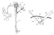
- FIG. 1is a view showing an endoscope as an example of a device used for performing a medical procedure in an embodiment, holding a capsule endoscope as a second observation device.
- FIG. 2is a perspective view of the distal end of the endoscope, showing a first observation device.
- FIG. 3illustrates is a holding state of the capsule endoscope in a partial cross-sectional view.
- FIG. 4is a view showing a process for holding the capsule endoscope.
- FIG. 5is a cross-sectional view showing the construction of the capsule endoscope.
- FIG. 6illustrates a patient laid on his back to be subject to a manipulation in an explanatory diagram.
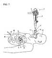
- FIG. 7is a view showing the endoscope inserted into the stomach.
- FIG. 8is a view showing the endoscope introduced from an opening formed in the stomach into the abdominal cavity.
- FIG. 9is a view showing the capsule endoscope that is projected.
- FIG. 10is a view showing the capsule endoscope attached to a magnet disposed outside of the abdominal wall.
- FIG. 11illustrates how a target site is confirmed by the capsule endoscope and the first observation device of the endoscope.
- FIG. 12is an example of an image of the first observation device superposed in an image of the capsule endoscope.
- FIG. 13is an explanatory diagram illustrating how a manipulation for treating a treatment target site is conducted by a forceps passed through a work channel.
- FIG. 14is a view showing the opening sutured after the endoscope and the capsule endoscope are brought back into the stomach.
- FIG. 15is a view showing the endoscope attached with a compact scope having a second observation device.
- FIG. 16is a view showing the compact scope curved in the abdominal cavity.
- FIG. 17is a view showing the second observation device provided on the distal end of an overtube.
- FIG. 18is a view showing the second observation device provided on a rising member of the overtube.
- FIG. 19is a cross-sectional view taken along the line A-A of FIG. 18 .
- FIG. 20illustrates the rising member raised from the position of FIG. 19 .
- FIG. 21is a schematic cross-sectional view of the human abdominal wall with an imaging capsule attached to the distal tip of a percutaneous manipulator placed through the abdominal wall. This capsule observes the action of a laparoscopic surgical instrument also placed through the abdominal wall, and sends the resulting images to an externally placed receiver via radio frequency transmission.
- FIG. 22is a cross-sectional schematic view of the abdominal wall illustrating an imaging capsule held by a laparoscopic grasping device in appropriate position for attachment to the distal tip of the percutaneous manipulator.
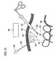
- FIG. 23is a cross-sectional schematic view of the abdominal wall illustrating a flexible endoscope holding an imaging capsule in a capsule holder in position for attachment to the distal tip of the percutaneous manipulator.
- FIG. 24is a cross-sectional schematic view of an embodiment of the imaging capsule illustrating how the imaging capsule is attached to the distal tip of the percutaneous manipulator by means of a spring clip.
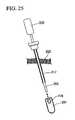
- FIG. 25is a cross-sectional schematic view of the devices of FIG. 24 illustrating that the percutaneous manipulator can alternatively be inserted through a trocar placed in the abdominal wall.
- FIG. 26is a cross-sectional schematic view of an alternative design for the spring clip holding the imaging capsule to the distal tip of the percutaneous manipulator.
- FIG. 27is a cross-sectional schematic view of an alternative design for a means of holding the imaging capsule to the distal tip of the percutaneous manipulator employing magnets.
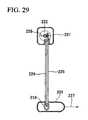
- FIG. 28is a schematic view of an alternative embodiment of a percutaneous manipulator with a control knob on the handle of the manipulator for changing the orientation of the imaging capsule attached to its distal tip.
- FIG. 29is a side-sectional view of the embodiment illustrated in FIG. 28 illustrating a mechanism by which the control knob changes the orientation of the imaging capsule.
- FIG. 30is a side-sectional view of the embodiment illustrated in FIG. 29 illustrating that rotation of the control knob changes the orientation of the imaging capsule at its distal tip by means of changing the position of the shaft parts relative to the manipulator.
- FIG. 31is a side-sectional view of an alternative embodiment of the control knob and mechanism for orienting the imaging capsule attached to the distal tip of the manipulator.
- FIG. 32is a side-sectional view of an alternative embodiment of the handle and mechanism of the percutaneous manipulator.
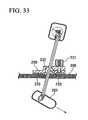
- FIG. 33is a side-sectional view of an attachment device that adheres to the exterior surface of the abdominal wall for fixing the position of the percutaneous manipulator.
- FIG. 34is a side-sectional view of an alternative embodiment of an attachment device that adheres to the exterior surface of the abdominal wall for fixing the position of the percutaneous manipulator.
- FIG. 35is a side-sectional view of an alternative embodiment of the percutaneous manipulator.
- a ratchet on the proximal end of the manipulatorcontrols the position of the attachment arm to which the imaging capsule is attached.
- An attachment devicefixes the position of the percutaneous manipulator with respect to the abdominal wall.
- FIG. 1shows a flexible endoscope (hereunder, called an endoscope) serving as a device used in the present embodiment, holding a capsule endoscope at the distal end of an insertion portion thereof.
- the endoscope 1has an extending insertion portion 3 which is to be inserted into a patient's body from an operation portion 2 operated by an operator.
- the insertion portion 3is slender and flexible.
- a distal end 4 of the insertion portion 3can be curved by angle knobs 5 of the operation portion 2 .
- an illuminating device 7 and a first observation device 6 for observing inside the bodyare disposed on a distal face 3 A of the insertion portion 3 .
- the first observation device 6comprises, for example, an observational optical system such as an object lens, and a CCD (Charged Coupled Device) as an imager.
- the illuminating device 7is configured to guide light illuminated from a light source unit outside of the body, by means of an optical fiber.
- an output signal from the imagermay be transmitted to a controller 24 described later through a signal wire passed through the insertion portion 3 .
- an output signal from the imagermay be transmitted to the controller 24 by wireless means.
- the illuminating device 7may comprise a publicly known light emission element (for example, light emitting diode) or the like.
- a fluid supply channel 8is a duct used for supplying a fluid into the body.
- a suction channel 9is a duct used for sucking a fluid from the body.
- Treatment toolsare disposed through a work channel 10 .
- the respective channels 8 to 10are extended from the insertion portion 3 toward the operation portion 2 .
- the endoscope 1is not limited to this configuration.
- the work channel 10may be used for suction work instead of omitting the suction channel 9 .
- a plurality of work channels 10may be provided.
- the proximal orifice of the work channel 10is also provided on a side of the operation portion 2 .
- the other channels 8 and 9are connected to a fluid supply device 21 and a suction device 22 through a universal cable 15 shown in FIG. 1 .
- Operation button 23 disposed on the operation portion 2permits supplying or sucking air and liquid.
- the endoscope 1is also connected to the controller 24 , through the universal cable.
- the controller 24 for controlling the endoscope 1is installed with an image processor and a light source, thus the controller 24 is capable of outputting various images (images) to a monitor 25 .
- FIG. 1shows a grasping forceps 30 as an example of a treatment tool passed through the work channel 10 of the endoscope 1 .
- the grasping forceps 30has a forceps operation portion 31 having a handle 32 movable in a back-and-forth based on the operator's operation.
- a wire 33is fixed to the handle 32 .
- the wire 33is led into a flexible forceps insertion portion 34 extending to the distal end of the forceps operation portion 31 .
- this forceps insertion portion 34is passed through the work channel 10 .
- a treatment portion 35is provided to the distal end of the forceps insertion portion 34 .
- the treatment portion 35is configured to support a pair of forceps members 37 on a supporting portion 36 so as to freely open.
- the pair of forceps members 37is connected to the wire 33 , and can be opened and closed according to a back-and-forth movement of the handle 32 .
- the treatment portion 35 of the grasping forceps 30 in this configurationholds a capsule endoscope 40 as a second observation device in the present embodiment.
- the capsule endoscope 40has an outline of a cylindrical shape with a spherical distal end.
- the proximal faceis provided with a radially extending groove 41 in a concave manner.
- Fixed to the groove 41is a pin 42 configured to transverse the groove 41 . Holding this pin 42 by the forceps members 37 serving as a holding part of the grasping forceps 30 provides a support to the capsule endoscope 40 by means of the grasping forceps 30 .
- the width and the depth of the groove 41are in a size which allows insertion and withdrawal of the treatment portion 35 . As shown in FIG. 1 and FIG.
- the capsule endoscope 40is abutted against the distal face 3 A of the insertion portion 3 .
- the outer diameter thereofis not greater than the outer diameter of the distal end 4 of the insertion portion 3 so as not to interfere with insertion into the body.
- the capsule endoscope 40has an approximately hemispherical transparent hood 45 on the distal end. Furthermore, it has a capsule type casing 46 having a flat proximal end except for the groove 41 . A pair of semicircular magnetic bodies 47 is fixed to the proximal end of the casing 46 so as to avoid the groove 41 .
- the magnetic body 47may be a hard magnetic body material which generates a magnetic force by itself, or a soft magnetic body which is magnetized when exposed to a magnetic field.
- a second observation portion 50serving as an observational optical device.
- the second observation portion 50has an object lens 51 and an imager 52 arranged in the imaging position of the object lens 51 , and is constructed so that the magnification can be changed by moving a zoom lens 55 by means of a zoom mechanism 54 .
- the second observation portion 50preferably comprises the zoom mechanism 54 , however the zoom mechanism 54 is a dispensable component in the present embodiment.
- an illumination part 56for illuminating the view field of the second observation portion 50 .
- the illumination part 56for example a plurality of LEDs (Light Emitting Diodes) are used.
- the second observation portion 50 and the illumination part 56are connected to a control circuit 57 .
- a control circuit 57Provided to the control circuit 57 ARE a camera control unit (CCU) connected to the imager 52 , a circuit which turns on the illumination part 56 , and so forth.
- CCUcamera control unit
- Connected furthermore to the control circuit 57are an antenna 58 and a battery 59 .
- the capsule endoscope 40obtains an observation image (endoscopic image) under light of the illumination part 56 .
- the observation imageis converted into electric signals and output to the control circuit 57 by the imager 52 .
- the control circuit 57sends the electric signals of the observation image to the antenna 58 and oscillates transmits them toward outside of the body as radio signals.
- the receiver 60 shown in FIG. 1receives these radio signals and outputs to the controller 24 of the endoscope. That is, an image of the capsule endoscope 40 (hereunder, called a second observation image) can be displayed on a monitor 25 via the receiver 60 .
- a second observation imagecan be displayed on a monitor 25 via the receiver 60 .
- Described hereunderis a manipulation for treating an organ or a tissue (hereunder, called a target site) serving as an object on which a desired medical procedure is performed, by inserting the endoscope 1 from a patient's mouth as a natural orifice of a living body.
- the natural orifice subject to the insertion of the endoscope 1is not limited to the mouth, and may be a nostril or the anus.
- treatments as a medical procedureare applicable to various actions such as suture, observation, incision, and cell sampling.
- a patient PTis laid on his back so that the abdomen AD is uppermost. Then a pneumoperitoneal needle 70 is pierced into the abdomen AD, and carbon dioxide gas or the like is sent into the abdominal cavity AC to expand the abdominal cavity. It is desirable to expand the abdominal cavity in order to ensure a space for performing a medical procedure in the abdominal cavity, however a pneumoperitoneum is not necessarily performed as long as a desired space can be ensured.
- a method of expanding the abdominal cavityis not limited to a method of expanding by a gas, and may be a publicly known lifting method so as to keep a space in the abdominal cavity.
- the timing to expand the abdominal cavitymay be after a device (for example, the endoscope 1 ) is introduced into the abdominal cavity.
- the endoscope 1is passed through from a mouthpiece 71 attached to the patient PT's mouth into the body.
- a mouthpiece 71attached to the patient PT's mouth into the body.
- an overtube 72is used in common.
- the overtube 72 used as a guide tube for inserting/withdrawing a device having an insertion portion such as the endoscope 1 , into/from the bodymay not be used. Instead of that, the device may be inserted into the body.
- the endoscope 1 at this timeis not attached with the capsule endoscope 40 .
- the fluid supply channel 8is used to send a gas into the stomach ST so as to expand the stomach ST.
- a device for incisionfor example a high frequency knife, is passed through the work channel 10 , and the stomach wall is incised.
- the incision siteis desirably an anterior wall of the stomach.
- the endoscope 1is withdrawn from the body, and then the grasping forceps 30 are passed through the work channel 10 .
- the back-and-forth movement of the handle 32 of the forceps operation portion 31provides the open-and-close movement of the pair of forceps members 37 , thereby holding the capsule endoscope 40 .
- the backward movement of the grasping forceps 30projects the magnetic bodies 47 disposed on the proximal end of the capsule endoscope 40 to abut against the distal face 3 A of the insertion portion 3 .
- the endoscope 1is inserted from the patient PT's mouth into the stomach ST while the capsule endoscope 40 is held.
- an image captured by the second observation portion 50 of the capsule endoscope 40is used.
- the insertion portion 3is introduced from an opening SO formed by incising the stomach wall, into the abdominal cavity AC.
- the state of target site Wshould be confirmed by the capsule endoscope 40 .
- the insertion portion 3is next curved toward the abdominal wall AW.
- Moving the grasping forceps 30 in the vicinity of the abdominal wall AWseparates the capsule endoscope 40 from the endoscope 1 .
- the capsule endoscope 40is rotated about the pin 42 (refer to FIG. 3 ) with respect to the grasping forceps 30 , and hung from the grasping forceps 30 .
- the magnetic bodies 47are directed toward the abdominal wall AW.
- the magnetic bodies 47are provided on the proximal end of the capsule endoscope 40 (the opposite side to the view field direction of the second observation portion 50 ).
- the direction of the magnetic bodies 47 configured toward the abdominal wall AWis not limited to this configuration.
- a magnetic bodymay be arranged in an optional position of the capsule endoscope 40 , such as a side of the capsule endoscope 40 , and a magnetic force is generated between this magnetic body and a magnetic body set outside of the body, so as to obtain an image of the abdominal cavity at a desired angle.
- a magnet 75is put on an outer surface AW 1 (also called the abdomen or the abdomen outer surface) of the abdominal wall AW. While confirming that the target site W can be observed by the capsule endoscope 40 on the display of the monitor 25 , the magnetic bodies 47 of the capsule endoscope 40 are attracted to the magnet 75 having the abdominal wall AW therebetween.
- the magnet 75is used for placing the capsule endoscope 40 on the abdominal wall AW using the magnetic force effect.
- a permanent magnetis used as the magnet 75 , however an electromagnet may be used.
- thisattaches the capsule endoscope 40 to the inner surface AW 2 of the abdominal wall AW, and does not drop even if the grasping forceps 30 is opened.
- the magnet 75may be previously put in the vicinity of the target site W of the abdominal wall AW, or may be disposed while the position of the capsule endoscope 40 is being searched.
- the insertion portion 3is curved again.
- the endoscope 1is moved forward to the target site W.
- the image of the first observation device 6is a localized image
- the image of the capsule endoscope 40is an image of a wide area where the distal end 4 of the insertion portion 3 enters, that is, an overhead view of the target site W. Therefore, by watching these two images, the position of the insertion portion 3 and the position of the target site W can be ascertained.
- image-processing for superimposing an image 77 of the capsule endoscope 40 into an image 76 of the first observation device 6 in the monitor 25permits the operator merely to confirm the image on one monitor 25 .
- the monitor 25shows the image 76 of the capsule endoscope 40 in a part of the image 77 of the first observation device 6 of the endoscope 1 , and the overall image can be readily ascertained by confirming these two images.
- These images 76 and 77can be switched by operating the buttons 23 of the endoscope 1 . Instead of displaying the partial superimposed image, these two images 76 and 77 may be displayed separately on the screen. Moreover, the images 76 and 77 may be separately displayed in two monitors.
- informative image as the second observation imagemay be obtained by manipulating the magnet 75 outside of the body to move the position and the view field direction of the capsule endoscope 40 as the second observation device while a medical procedure is performed in the abdominal cavity AC.
- the grasping forceps 30is withdrawn, and a treatment tool is passed through the work channel 10 instead.
- a tissue of the target site Wis resected by using a resection forceps 78 while watching the image of the first observation device 6 and the image of the capsule endoscope 40 as the second observation device. Magnifying the size of the image 76 of the first observation device 6 provides magnified image of the target site W and the resection forceps 78 , thereby facilitating the operator's operation.
- the constructionmay be such that the size of the image 77 of the first observation device 6 and the size of the second image 76 (second observation image) of the second observation portion 50 of the capsule endoscope 40 can be selectively switched according to the operation of the operator.
- the constructionmay be such that when the device is made to approach the target site, the image 77 of the first observation device is displayed on a part of the second image 76 of the second observation device, and then when a medical procedure is performed, the image processing is switched so that the second image 77 of the second observation portion 50 is displayed on a part of the image 77 of the first observation device 6 .
- the treatment of the target site Wis incision of a tissue for example, then after the tissue is incised, a treatment tool for suture is passed through the endoscope 1 and the incised orifice is sutured. After that, the grasping forceps 30 is passed through the endoscope 1 again, and the capsule endoscope 40 is collected.
- the treatment portion 35 of the grasping forceps 30is inserted into the groove 41 in the capsule endoscope 40 , and the pin 42 is hold between the pair of forceps members 37 which freely opens and closes.
- the magnet 75 outside of the bodyis removed. Since the capsule endoscope 40 comes off from the inner surface AW 2 of the abdominal wall AW and is hung from the grasping forceps 30 , if the grasping forceps 30 is moved backward, the magnetic bodies 47 of the capsule endoscope 40 are abutted against the distal face 3 A of the insertion portion 3 .
- the endoscope 1is brought back into the stomach ST from the orifice SO in the stomach wall and withdrawn from the patient PT's mouth in this state, and then the capsule endoscope 40 is taken out to outside of the body. Furthermore, inserting the endoscope 1 through which the treatment tool for suture passed therethrough is inserted from the mouth again, and the orifice SO in the stomach wall is sutured. As shown in FIG. 14 , after the suture of the orifice SO is completed, the endoscope 1 is withdrawn from the patient, and the pressure on the abdominal cavity AC is removed, after which the pneumoperitoneal needle 70 is withdrawn, and the manipulation is completed.
- the timing when the capsule endoscope 40 serving as the second observation device will be taken out from the bodyis set before suture, however it may be brought back into the stomach ST before the suture, and taken out from the stomach ST after the suture.
- the capsule endoscope 40 that can be used apart from the endoscope 1is arranged as the second observation device on the inner surface AW 2 of the abdominal wall AW. Therefore, an image in a wide view field can be obtained. Since images including the target site W and the insertion portion 3 from different angles can be obtained, the operator can readily ascertain the positional relation, the direction, and the movement of respective sites, thus facilitating the manipulation.
- the endoscope 1has been operated to move the first observation device 6 to change the angle and the view field so as to identify the target site W, thus loading a burden onto the operator and the patient.
- the present embodimentcan solve such a problem.
- the capsule endoscope 40When the abdomen AD of the patient PT is faced upwards, the capsule endoscope 40 is arranged on the inner surface AW 2 of the abdominal wall AW. Therefore, the image of the capsule endoscope 40 becomes an image as if the operator overlooks the insertion portion 3 , the treatment tool, and the target site W. Furthermore, the manipulation is further facilitated by adjusting the direction of the capsule endoscope 40 or performing image processing so that the vertical, sideways, and lengthwise directions recognized by the operator are matched with the actual directions.
- the capsule endoscope 40 arranged on the inner surface AW 2 of the abdominal wall AW by using the magnetic bodies 47does not provide pain to a patient. Since the capsule endoscope 40 can be arranged and detached by simply putting on/taking off the magnet 75 outside of the body, the operation is facilitated. In particular, complicated operations become unnecessary on the inner surface AW 2 side of the abdominal cavity AD.
- the magnet 75may be an electromagnet.
- the capsule endoscope 40may have a sucker instead of the magnetic bodies 47 . By attaching it onto the inner surface AW 2 of the abdominal wall AW by means of a sucker, a similar effect to the above can be obtained.
- a recessmay be provided in the outer periphery of the proximal end of the capsule endoscope 40 so as to attach a clip to clamp the inner surface AW 2 of the abdominal wall AW to the recess.
- the clipenables the capsule endoscope 40 to be fixed to the abdominal wall AW, and a similar effect to the above can be obtained.
- the clipis passed through the work channel as a treatment tool.
- the clipmay be previously and integrally attached onto the outer periphery of the capsule endoscope 40 .
- the insertion portion 3 of the endoscope 1is fixed with a small scope 80 as a second observation device in the present embodiment, by a connection member 82 .
- the small scope 80is an endoscope exclusively for observation, having an illuminating device 84 and a second observation device 85 on the distal end of a flexible insertion portion 81 , but not having various channels so as to decrease the diameter.
- the insertion portion 81is extended along the insertion portion 3 and is connected by the connection member 82 .
- the distal side from the part connected by the connection member 82becomes a curvable portion 83 .
- the position where the insertion portion 81 is fixed to the insertion portion 3is the proximal side from the curvable portion 83 , being a position not interfering with curving operations of the respective curvable portions 4 and 83 .
- the curving operationis performed by an operation portion on the hand side.
- the diameter of the insertion portion 81is sufficiently narrow compared to the diameter of the insertion portion 3 , being a size not interfering with insertion/withdrawal of the endoscope 1 .
- the illuminating device 84 and the second observation device 85 of the small scope 80have, for example similar constructions to those of the illuminating device 7 and the first observation device 6 of the endoscope 1 , and are connected to the controller 24 through the inside of the small scope 80 .
- the endoscope 1 attached with the small scope 80is inserted from the patient PT's mouth into the stomach ST.
- a high frequency knifeis passed through the work channel 10 of the endoscope 1 , and the stomach wall is incised to form the opening SO.
- the endoscope 1is introduced from the opening SO into the abdominal cavity AC, and the target site W is confirmed by using the first observation device 6 and the second observation device 85 .
- moving the second observation device 85 a direction away from the first observation device 6 by curving the curvable portion 83 of the small scope 80provides two images obtained from different viewpoints.
- the forcepsis passed through the work channel 10 of the endoscope 1 , and the target site W is treated while confirming the two images.
- the two images obtained by the first observation device 6 and the second observation device 85may be displayed either simultaneously or selectively.
- the curvable portion 83 of the small scope 80is brought back along the insertion portion 3 , and then the insertion portion 3 is withdrawn from the abdominal cavity AC back into the stomach.
- the treatment tool for sutureis passed through the work channel 10 , and the opening SO in the stomach wall is sutured, and then the endoscope 1 is withdrawn from the body.
- the small scope 80 along the insertion portion 3is used, enabling to arrange the second observation device 85 away from the first observation device 6 at a predetermined distance. Since two images from different angles can be obtained, the operator can readily ascertain the positional relation, the direction, and the movement of respective sites, further facilitating the manipulation.
- the constructionis such that the second observation device 85 is arranged in a position back from the first observation device 6 , or that a wide-angle lens is attached to the second observation device 85 , so as to enable to observe a wider view field than that of the first observation device 6 , then an image from a wide view field can be obtained as a second observation image, further facilitating the manipulation in this case too.
- a curving operation of the curvable portion 83 of the small scope 80 and/or back-and-forth moving operation of the small scope 80may be performed so as to move the position of second observation device 85 to a desired location (to change the viewpoint of the second observation device 85 ).
- the recovery operationcan be omitted.
- the position of the second observation device 85can be readily changed in the middle of manipulation, enabling to obtain optimum images according to the type of manipulation and its progress.
- a third embodimentis described in detail with reference to the drawings.
- the present embodimentis characterized in using an overtube (also called a guide tube or a device) for passing an endoscope therethrough.
- an overtubealso called a guide tube or a device
- an overtube 90is made from a flexible and slender barrel, inside of which the endoscope 1 can be inserted in a back-and-forth movable manner.
- a second observation device 91having an image-capturing face facing forward. This second observation device 91 captures an image in a range illuminated by the illuminating device 7 on the endoscope 1 side, however another illuminating device may be arranged around the second observation device 91 .
- the endoscope 1When a manipulation is performed, the endoscope 1 is guided into the abdominal cavity AC together with the overtube 90 , and the target site W is confirmed by respective images of the first observation device 6 and the second observation device 91 . After the distal end of the endoscope 1 is pushed out from the overtube 90 , the manipulation is performed.
- the first observation device 6 provided on the endoscope 1obtains an image from a position close to the treatment tool and the target site W. Since the second observation device 91 provided on the overtube 90 is in a position away from the first observation device 6 , it obtains an image of a wide view field including the distal end of the endoscope 1 , the treatment tool, and the target site W. The operator performs the procedure while simultaneously or selectively confirming two images in different image-capturing positions.
- the manipulationcan be performed using two images captured from different points in the insertion direction of the endoscope 1 , the positional relation between the target site W and the treatment tool are readily confirmed, facilitating the manipulation.
- the second observation device 91is provided on the distal end of the overtube, positioning is easy.
- the size of the view field of the second observation device 91can be readily adjusted by relatively changing the distance from the distal area of the overtube 90 to the target site W. Such an adjustment of distance can be achieved by the projected amount of the endoscope 1 from the overtube 90 .
- rotation and/or back-and-forth moving operation of the overtube 90may be performed so as to change the position of the second observation device 91 to a desired condition (to change the viewpoint of the second observation device 91 ).
- a fourth embodimentis described in detail with reference to the drawings.
- the present embodimentis characterized in that the distal end of an overtube is attached with a second observation device in a positionally adjustable manner.
- an elongated slit 101is formed along the lengthwise direction.
- the distal end side of the slit 101is fixed with a pin 102 so as to transverse the slit 101 .
- This pin 102is attached with a proximal end 103 A of a rising member 103 .
- the rising member 103has a shape to fit in the slit 101 , and in a condition where it is accommodated in the slit 101 , the outline of the overtube 100 is hardly changed.
- the distal end 103 B of the rising member 103is provided with a second observation device 104 oriented radially outward.
- An electric signal output from the second observation device 104is output to a cable 105 .
- the cable 105is led out from the vicinity of the pin 102 , and led out through a lumen 106 on the inner peripheral side of the overtube 100 , to a proximal end 107 on the hand side.
- the cable 105is led out from the proximal end 107 , and the construction is such that an image can be obtained by connecting a connector 108 to the controller 24 (refer to FIG. 1 ).
- the proximal end 107is provided with a slide member 109 .
- the slide member 109is slidable in the lengthwise direction of the overtube 100 , and a wire 110 is fixed inside thereof.
- the wire 110is guided through the lumen 106 of the overtube 100 to the distal end, and fixed to a distal side further from the pin 102 on the proximal end 103 A of the rising member 103 .
- the wire 110has a flexibility but a predetermined rigidity, and is capable of raising the rising member 103 and pulling it into the slit 101 , by moving the wire 110 back-and-forth.
- the overtube 100 and the endoscope 1are guided through the opening SO formed in the stomach ST, into the abdominal cavity AC.
- the operatormoves the slide member 109 backward.
- the wire 110pulls the proximal end 103 A of the rising member 103 , to rotate the rising member 103 about the pin 102 .
- the rising member 103rises so as to separate the second observation device 104 from the side face 111 of the overtube 110 , and stops in a position approximately orthogonal to the lengthwise direction of the overtube 100 .
- the second observation device 104is arranged in a position away from the side face 111 of the overtube 100 , and its observation view field direction is oriented forward in the insertion direction of the overtube 100 into the body. In this manner, by changing the position of the second observation device 104 , an image obtained by the second observation device 104 becomes similar to an image in a condition where the target site W and the treatment tool are overlooked from the rear. The operator performs the manipulation while confirming two images having different image-capturing positions.
- the procedurecan be performed using two images captured from different points in the insertion direction of the endoscope 1 , the positional relation between the target site W and the treatment tool are readily confirmed, facilitating the procedure.
- the second observation device 104can be arranged in the position away from the overtube 100 , an image can be obtained from a different angle and a different distance from those of an image of the first observation device 6 , facilitating the confirmation of position of the treatment tool and the like.
- the image of the second observation device 104becomes an image as if the target site W of the patient PT lying on his back is overlooked. Therefore the operator can readily and sensuously specify the positional relation.
- the range of the second observation image obtained by the second observation device 104can be readily adjusted by relatively moving the position of the distal area of the overtube 100 with respect to the endoscope 1 and the target site W.
- the second observation device 104can be pulled in to fit the outline of the overtube 100 , when it is not used. Therefore the insertion/withdrawal can be smoothly performed without enlarging the outer diameter of the overtube 100 .
- rotation and/or back-and-forth moving operation of the overtube 100may be performed so as to change the position of the second observation device 104 to a desired condition (to change the viewpoint of the second observation device 104 ).
- the arrangementmay be such that only an image of the second observation device is used when the insertion portion 3 is faced to the target site W, and only an image of the first observation device 6 is used when an actual procedure is performed.
- the endoscope 1has a plurality of work channels 10 , manipulation can be performed using a plurality of treatment tools at the same time, improving the treatment properties.
- the arrangementmay be such that the endoscope 1 is inserted from a natural orifice of the living body into another hollow organ, not limiting to the stomach ST, and then an opening is formed in the wall of the hollow organ, so as to introduce the endoscope into the abdominal cavity AC.
- the arrangementwhen the capsule endoscope 40 is introduced into the abdominal cavity AC, the arrangement may be such that an exclusive introducing device is used, and after the capsule endoscope 40 is arranged, the exclusive introducing device is withdrawn from the body, and the endoscope 1 is inserted instead.
- the introducing devicein this case it is sufficient to have a construction without the first observation device 6 .
- the introducing devicemay have a construction where a holding part is fixed to the distal end, without having the work channel 10 capable of exchanging treatment tools.
- the manipulationmay be performed by selectively displaying only one out of two images. For example, only an image of the second observation device is used when the location is confirmed, and only an image of the first observation device is used during a manipulation.
- the hollow organ formed with the orifice SOis not limited to the stomach ST.
- itmay be an esophagus, a duodenum, a small intestine, a large intestine, a uterus, a bladder, and the like.
- the device needed for performing a desired manipulationis not limited to the endoscope comprising the observation device and the work channel described in the above embodiments.
- a devicehereunder, called a treatment device for convenience
- a treatment devicecomprising a treatment portion for performing a desired treatment, on the distal side of the insertion portion to be inserted into the body, and provided with an operation portion capable of operating this treatment portion from outside of the body.
- an image from the observation devicemay be used as a first observation image.
- various modesmay be considered such as using the abovementioned capsule endoscope in common.
- a devicecomprising a lumen through which the treatment tool can be inserted, in the insertion portion, but not having an observation mechanism.
- FIG. 21provides an overview of the use of this new method of imaging the inside of the lumen of the abdominal cavity.
- the imaging capsule 201is mounted via an easily attachable/detachable connecting means to the distal end of a percutaneous manipulator 202 .
- the imaging capsuleis used to observe the inside of the lumen of the abdominal cavity 203 and to guide surgery or therapy within the lumen of the abdominal cavity. Images created by the imaging capsule are sent by radio transmission 240 to a receiver 209 located next to the patient.
- One or more trocars 204 inserted through the patient's abdominal wallallow the introduction of laparoscopic surgical instruments 206 into the lumen of the abdominal cavity 203 .
- the surgical instrumentsare used to manipulate, cut, burn, suture or perform other therapeutic activity on organs accessible within the lumen of the abdominal cavity.
- organsinclude gastrointestinal organs such as the intestines 207 and stomach 208 , organs of the pancreatic and biliary systems, reproductive organs, etc.
- the percutaneous manipulatormakes a very small puncture in the abdominal wall (e.g., 1 to 3 mm) and thereby introduces minimal trauma to abdominal wall tissue, speeding healing and reducing post-procedural pain.
- both the capsule and the introducercan be disposable, eliminating the need to reprocess these devices.
- the imaging capsulePrior to use, the imaging capsule must be introduced into the lumen of the abdominal cavity 203 .
- One means of doing thisis to put the capsule into the lumen of the abdominal cavity via a large trocar 204 .
- a laparoscope 212 with a therapeutic channel 213 and a grasping device 214is used to hold the imaging capsule 201 and connect it to the distal tip of the percutaneous manipulator 202 . This operation is illustrated in FIG. 22 .
- the video capsulemay be brought into the lumen of the abdominal cavity 3 by means of a flexible endoscope 215 which has entered the peritoneal cavity by means of an opening in the abdominal wall, the gastric wall, the intestinal wall, or other means of access to the lumen of the abdominal cavity.
- a holder 216holds the imaging capsule 201 via suction, a friction fit, or other suitable means until it is attached to the end of the percutaneous manipulator 202 .
- FIG. 24illustrates that to reduce the overall size of the puncture in the abdominal wall 205 , the percutaneous manipulator 202 can be placed through the tissue directly.
- the percutaneous manipulator 202could be introduced through the abdominal wall 205 through a trocar 217 of appropriate size.
- the video capsulecan be held on the distal tip of the percutaneous manipulator via various types of spring clips 218 .
- spring clips 218can be employed, such as magnets 219 , as illustrated in FIG. 27 .
- FIG. 28illustrates an alternative embodiment of the percutaneous manipulator 202 that has a handle 221 with a control knob 222 to change the orientation of the imaging capsule 201 which is connected to the tip of the manipulator.
- the opening 223 for the connectoris on the side wall of the capsule, instead of the end wall of the capsule.
- the capsuleis attached to the distal tip of the manipulator via a spring clip 223 .
- FIG. 29illustrates one embodiment of a mechanism for controlling the position at which the capsule is held.
- the manipulator shaftis constructed of two parts 224 and 225 that connect to the imaging capsule via a spring clip 218 .
- the relative position of shaft parts 224 and 225is controlled by a control knob 222 on the handle 221 .
- rotating the control knobchanges the relative position of the shaft parts 224 and 225 changing the orientation of the imaging capsule 1 .
- an indication mark 226 on the control knobshows the change in position of the capsule's direction of view 227 .
- the capsule's direction of view 227 of the indication mark 226is compared between FIGS. 29 and 30 .
- FIG. 31illustrates that various configurations of the gearing in the handle 221 of the percutaneous manipulator may be employed in order to change the sensitivity of the imaging capsule's orientation with respect to changes in position of the control knob 222 .
- FIG. 32illustrates an alternative embodiment of the percutaneous manipulator's handle 228 .
- rotating the adjustment nut 229 at the proximal end of the manipulatorchanges the orientation of the imaging capsule 201 at its tip.
- FIG. 33illustrates another embodiment of the invention wherein the percutaneous manipulator is held in position with respect to abdominal wall via an attachment device 230 .
- the attachment devicehas a locking nut 231 that compresses a pivot ball 232 to lock the shaft of the percutaneous manipulator at the correct height and correct angle with respect to the abdominal wall 205 .
- the attachment device 230is held to the abdominal wall 205 by means of double-sided adhesive tape 233 placed between the attachment device 230 and the patient's skin overlying the abdominal wall.
- FIG. 34illustrates another embodiment of the attachment device.
- the shaft of the percutaneous manipulator 202passes through a rubber membrane 234 that slides in a slot in the attachment device.
- the locking nut 231is tightened to hold the manipulator in position with respect to the abdominal wall 205 .
- FIG. 35illustrates another embodiment of the present invention.
- the distal end of the percutaneous manipulator 202has a hinge 235 allowing movement of an attachment arm 236 that connects to the imaging capsule 201 by means of a spring clip 218 .
- the position of the attachment arm 236is controlled by a rod 37 in the percutaneous manipulator.
- the rod 237is connected to the attachment arm 236 by means of a flexible member 238 .
- the flexible memberis joined to the rod 237 whereby movement of the rod causes the attachment arm to rotate about the hinge 235 .
- a ratchet 239 at the proximal end of the deviceallows the position of the rod 237 to be changed easily, yet holds the rod in the selected position.
- the objective of the inventionis to control the direction of view of an imaging capsule placed in the intraperitoneal space via a manipulator that is passed through a small puncture of the abdominal wall.
- the advantage of this invention over a standard laparoscopeis found in the relatively small diameter of the manipulator shaft compared to the relatively large diameter of the imaging capsule.
- the compact manipulator shaftcan be inserted through the abdominal wall by means of a very small stab incision that will heal quickly with reduced post-procedure pain.
- the imaging capsuleis of a sufficient size to produce high resolution images of intraperitoneal tissue.
Landscapes
- Health & Medical Sciences (AREA)
- Life Sciences & Earth Sciences (AREA)
- Surgery (AREA)
- Biomedical Technology (AREA)
- Medical Informatics (AREA)
- Optics & Photonics (AREA)
- Pathology (AREA)
- Radiology & Medical Imaging (AREA)
- Biophysics (AREA)
- Engineering & Computer Science (AREA)
- Physics & Mathematics (AREA)
- Heart & Thoracic Surgery (AREA)
- Nuclear Medicine, Radiotherapy & Molecular Imaging (AREA)
- Molecular Biology (AREA)
- Animal Behavior & Ethology (AREA)
- General Health & Medical Sciences (AREA)
- Public Health (AREA)
- Veterinary Medicine (AREA)
- Endoscopes (AREA)
- Media Introduction/Drainage Providing Device (AREA)
Abstract
Description
Claims (5)
Priority Applications (1)
| Application Number | Priority Date | Filing Date | Title |
|---|---|---|---|
| US11/650,123US8475361B2 (en) | 2006-01-06 | 2007-01-05 | Percutaneous or natural-orifice medical procedure and system therefor |
Applications Claiming Priority (3)
| Application Number | Priority Date | Filing Date | Title |
|---|---|---|---|
| US11/327,788US20070161855A1 (en) | 2006-01-06 | 2006-01-06 | Medical procedure through natural body orifice |
| US75911906P | 2006-01-13 | 2006-01-13 | |
| US11/650,123US8475361B2 (en) | 2006-01-06 | 2007-01-05 | Percutaneous or natural-orifice medical procedure and system therefor |
Related Parent Applications (1)
| Application Number | Title | Priority Date | Filing Date |
|---|---|---|---|
| US11/327,788Continuation-In-PartUS20070161855A1 (en) | 2006-01-06 | 2006-01-06 | Medical procedure through natural body orifice |
Publications (2)
| Publication Number | Publication Date |
|---|---|
| US20070255100A1 US20070255100A1 (en) | 2007-11-01 |
| US8475361B2true US8475361B2 (en) | 2013-07-02 |
Family
ID=38228339
Family Applications (1)
| Application Number | Title | Priority Date | Filing Date |
|---|---|---|---|
| US11/650,123Expired - Fee RelatedUS8475361B2 (en) | 2006-01-06 | 2007-01-05 | Percutaneous or natural-orifice medical procedure and system therefor |
Country Status (5)
| Country | Link |
|---|---|
| US (1) | US8475361B2 (en) |
| EP (1) | EP1980194B1 (en) |
| JP (1) | JP4898709B2 (en) |
| TW (1) | TW200744518A (en) |
| WO (1) | WO2007078003A1 (en) |
Cited By (62)
| Publication number | Priority date | Publication date | Assignee | Title |
|---|---|---|---|---|
| US20070251976A1 (en)* | 2000-11-20 | 2007-11-01 | Medigus Ltd. | Stapler for endoscopes |
| US20100234686A1 (en)* | 2006-05-12 | 2010-09-16 | Mauna Kea Technologies | Endoscopy device and method for simultaneous observation of several zones of interest |
| US20110087266A1 (en)* | 2009-10-09 | 2011-04-14 | Conlon Sean P | Loader for exchanging end effectors in vivo |
| US20130225920A1 (en)* | 2012-02-23 | 2013-08-29 | Covidien Lp | Surgical support assembly |
| US20130296648A1 (en)* | 2008-11-12 | 2013-11-07 | Trice Orthopedics, Inc. | Minimally invasive imaging systems |
| US9125681B2 (en) | 2012-09-26 | 2015-09-08 | Ethicon Endo-Surgery, Inc. | Detachable end effector and loader |
| US9186203B2 (en) | 2009-10-09 | 2015-11-17 | Ethicon Endo-Surgery, Inc. | Method for exchanging end effectors In Vivo |
| US20160095501A1 (en)* | 2006-12-21 | 2016-04-07 | Intuitive Surgical Operations, Inc. | Off-axis visualization systems |
| US9451937B2 (en) | 2013-02-27 | 2016-09-27 | Ethicon Endo-Surgery, Llc | Percutaneous instrument with collet locking mechanisms |
| US9610007B2 (en) | 2014-01-13 | 2017-04-04 | Trice Medical, Inc. | Fully integrated, disposable tissue visualization device |
| US10004558B2 (en) | 2009-01-12 | 2018-06-26 | Ethicon Endo-Surgery, Inc. | Electrical ablation devices |
| US20180256854A1 (en)* | 2013-11-29 | 2018-09-13 | Sharp Kabushiki Kaisha | In-body image capturing device, accessory for support tube of in-body image capturing device, and fixing tool for in-body image capturing device |
| US10105141B2 (en) | 2008-07-14 | 2018-10-23 | Ethicon Endo-Surgery, Inc. | Tissue apposition clip application methods |
| US10172669B2 (en) | 2009-10-09 | 2019-01-08 | Ethicon Llc | Surgical instrument comprising an energy trigger lockout |
| US10206709B2 (en) | 2012-05-14 | 2019-02-19 | Ethicon Llc | Apparatus for introducing an object into a patient |
| US10251636B2 (en) | 2015-09-24 | 2019-04-09 | Ethicon Llc | Devices and methods for cleaning a surgical device |
| US10258406B2 (en) | 2011-02-28 | 2019-04-16 | Ethicon Llc | Electrical ablation devices and methods |
| US10265130B2 (en) | 2015-12-11 | 2019-04-23 | Ethicon Llc | Systems, devices, and methods for coupling end effectors to surgical devices and loading devices |
| US10278761B2 (en) | 2011-02-28 | 2019-05-07 | Ethicon Llc | Electrical ablation devices and methods |
| US10278588B2 (en) | 2005-02-02 | 2019-05-07 | Intuitive Surgical Operations, Inc. | Electrophysiology mapping and visualization system |
| US10314565B2 (en) | 2015-08-26 | 2019-06-11 | Ethicon Llc | Surgical device having actuator biasing and locking features |
| US10314638B2 (en) | 2015-04-07 | 2019-06-11 | Ethicon Llc | Articulating radio frequency (RF) tissue seal with articulating state sensing |
| US10314603B2 (en) | 2008-11-25 | 2019-06-11 | Ethicon Llc | Rotational coupling device for surgical instrument with flexible actuators |
| US10335196B2 (en) | 2015-08-31 | 2019-07-02 | Ethicon Llc | Surgical instrument having a stop guard |
| US10342579B2 (en) | 2014-01-13 | 2019-07-09 | Trice Medical, Inc. | Fully integrated, disposable tissue visualization device |
| US10342598B2 (en) | 2012-08-15 | 2019-07-09 | Ethicon Llc | Electrosurgical system for delivering a biphasic waveform |
| US10368729B2 (en) | 2005-02-02 | 2019-08-06 | Intuitive Surgical Operations, Inc. | Methods and apparatus for efficient purging |
| US10405886B2 (en) | 2015-08-11 | 2019-09-10 | Trice Medical, Inc. | Fully integrated, disposable tissue visualization device |
| US10463237B2 (en) | 2005-02-02 | 2019-11-05 | Intuitive Surgical Operations, Inc. | Delivery of biological compounds to ischemic and/or infarcted tissue |
| US10470643B2 (en) | 2006-06-14 | 2019-11-12 | Intuitive Surgical Operations, Inc. | In-vivo visualization systems |
| US10478248B2 (en) | 2007-02-15 | 2019-11-19 | Ethicon Llc | Electroporation ablation apparatus, system, and method |
| US10492880B2 (en) | 2012-07-30 | 2019-12-03 | Ethicon Llc | Needle probe guide |
| US10603117B2 (en) | 2017-06-28 | 2020-03-31 | Ethicon Llc | Articulation state detection mechanisms |
| US10675009B2 (en) | 2015-11-03 | 2020-06-09 | Ethicon Llc | Multi-head repository for use with a surgical device |
| US10702257B2 (en) | 2015-09-29 | 2020-07-07 | Ethicon Llc | Positioning device for use with surgical instruments |
| US10751109B2 (en) | 2014-12-22 | 2020-08-25 | Ethicon Llc | High power battery powered RF amplifier topology |
| US10751117B2 (en) | 2016-09-23 | 2020-08-25 | Ethicon Llc | Electrosurgical instrument with fluid diverter |
| US10779882B2 (en) | 2009-10-28 | 2020-09-22 | Ethicon Endo-Surgery, Inc. | Electrical ablation devices |
| US10779876B2 (en) | 2011-10-24 | 2020-09-22 | Ethicon Llc | Battery powered surgical instrument |
| US10799284B2 (en) | 2017-03-15 | 2020-10-13 | Ethicon Llc | Electrosurgical instrument with textured jaws |
| US10856934B2 (en) | 2016-04-29 | 2020-12-08 | Ethicon Llc | Electrosurgical instrument with electrically conductive gap setting and tissue engaging members |
| US10912543B2 (en) | 2015-11-03 | 2021-02-09 | Ethicon Llc | Surgical end effector loading device and trocar integration |
| US10939909B2 (en) | 2012-12-13 | 2021-03-09 | Ethicon Llc | Circular needle applier with articulating and rotating shaft |
| US10959806B2 (en) | 2015-12-30 | 2021-03-30 | Ethicon Llc | Energized medical device with reusable handle |
| US10959771B2 (en) | 2015-10-16 | 2021-03-30 | Ethicon Llc | Suction and irrigation sealing grasper |
| US10987156B2 (en) | 2016-04-29 | 2021-04-27 | Ethicon Llc | Electrosurgical instrument with electrically conductive gap setting member and electrically insulative tissue engaging members |
| US11033323B2 (en) | 2017-09-29 | 2021-06-15 | Cilag Gmbh International | Systems and methods for managing fluid and suction in electrosurgical systems |
| US11033325B2 (en) | 2017-02-16 | 2021-06-15 | Cilag Gmbh International | Electrosurgical instrument with telescoping suction port and debris cleaner |
| US11090103B2 (en) | 2010-05-21 | 2021-08-17 | Cilag Gmbh International | Medical device |
| US11337594B2 (en) | 2006-09-01 | 2022-05-24 | Intuitive Surgical Operations, Inc. | Coronary sinus cannulation |
| US11406250B2 (en) | 2005-02-02 | 2022-08-09 | Intuitive Surgical Operations, Inc. | Methods and apparatus for treatment of atrial fibrillation |
| US11478152B2 (en) | 2005-02-02 | 2022-10-25 | Intuitive Surgical Operations, Inc. | Electrophysiology mapping and visualization system |
| US11484358B2 (en) | 2017-09-29 | 2022-11-01 | Cilag Gmbh International | Flexible electrosurgical instrument |
| US11484191B2 (en) | 2013-02-27 | 2022-11-01 | Cilag Gmbh International | System for performing a minimally invasive surgical procedure |
| US11490951B2 (en) | 2017-09-29 | 2022-11-08 | Cilag Gmbh International | Saline contact with electrodes |
| US11497546B2 (en) | 2017-03-31 | 2022-11-15 | Cilag Gmbh International | Area ratios of patterned coatings on RF electrodes to reduce sticking |
| US11547446B2 (en) | 2014-01-13 | 2023-01-10 | Trice Medical, Inc. | Fully integrated, disposable tissue visualization device |
| US11622753B2 (en) | 2018-03-29 | 2023-04-11 | Trice Medical, Inc. | Fully integrated endoscope with biopsy capabilities and methods of use |
| US11779195B2 (en) | 2006-09-01 | 2023-10-10 | Intuitive Surgical Operations, Inc. | Precision control systems for tissue visualization and manipulation assemblies |
| US11957342B2 (en) | 2021-11-01 | 2024-04-16 | Cilag Gmbh International | Devices, systems, and methods for detecting tissue and foreign objects during a surgical operation |
| US12035889B2 (en) | 2008-07-22 | 2024-07-16 | Trice Medical, Inc. | Tissue modification devices and methods of using the same |
| US12408824B2 (en) | 2005-02-02 | 2025-09-09 | Intuitive Surgical Operations, Inc. | Tissue visualization and manipulation system |
Families Citing this family (148)
| Publication number | Priority date | Publication date | Assignee | Title |
|---|---|---|---|---|
| US7429259B2 (en) | 2003-12-02 | 2008-09-30 | Cadeddu Jeffrey A | Surgical anchor and system |
| US7618413B2 (en) | 2005-06-22 | 2009-11-17 | Boston Scientific Scimed, Inc. | Medical device control system |
| SG132553A1 (en)* | 2005-11-28 | 2007-06-28 | Pang Ah San | A device for laparoscopic or thoracoscopic surgery |
| US20070163585A1 (en)* | 2006-01-13 | 2007-07-19 | Olympus Medical Systems Corp. | Method for accessing abdominal cavity and medical procedure via natural orifice |
| US7988656B2 (en)* | 2006-01-13 | 2011-08-02 | Olympus Medical Systems Corp. | Natural orifice medical operation and endoscopic overtube |
| US20080015413A1 (en)* | 2006-02-22 | 2008-01-17 | Olympus Medical Systems Corporation | Capsule endoscope system and medical procedure |
| JP2009535161A (en) | 2006-04-29 | 2009-10-01 | ボード・オブ・リージエンツ,ザ・ユニバーシテイ・オブ・テキサス・システム | Device for use in transmural and intraluminal surgery |
| US20100076261A1 (en)* | 2006-09-28 | 2010-03-25 | Medvision Inc. | Examination device |
| ATE514382T1 (en) | 2006-11-30 | 2011-07-15 | Wilson Cook Medical Inc | FABRIC ANCHOR FOR SEAM CLOSURE OF PERFORATIONS |
| US9456877B2 (en) | 2006-12-01 | 2016-10-04 | Boston Scientific Scimed, Inc. | Direct drive instruments and methods of use |
| US8814779B2 (en) | 2006-12-21 | 2014-08-26 | Intuitive Surgical Operations, Inc. | Stereoscopic endoscope |
| US8556807B2 (en) | 2006-12-21 | 2013-10-15 | Intuitive Surgical Operations, Inc. | Hermetically sealed distal sensor endoscope |
| EP1938758B1 (en)* | 2006-12-28 | 2018-08-29 | Olympus Corporation | Endoscopic treatment tool |
| US20080177141A1 (en)* | 2007-01-24 | 2008-07-24 | Hsien-Ming Wu | Memory-type two-section endoscopic system |
| ATE514386T1 (en) | 2007-02-28 | 2011-07-15 | Wilson Cook Medical Inc | INTESTINAL BYPASS USING MAGNETS |
| US7815662B2 (en) | 2007-03-08 | 2010-10-19 | Ethicon Endo-Surgery, Inc. | Surgical suture anchors and deployment device |
| US8075572B2 (en) | 2007-04-26 | 2011-12-13 | Ethicon Endo-Surgery, Inc. | Surgical suturing apparatus |
| US8100922B2 (en) | 2007-04-27 | 2012-01-24 | Ethicon Endo-Surgery, Inc. | Curved needle suturing tool |
| EP3375479B1 (en) | 2007-05-18 | 2023-03-22 | Boston Scientific Scimed, Inc. | Medical drive systems |
| JP4472728B2 (en)* | 2007-06-14 | 2010-06-02 | オリンパスメディカルシステムズ株式会社 | Endoscope system |
| JP2008307226A (en)* | 2007-06-14 | 2008-12-25 | Olympus Medical Systems Corp | Endoscope system |
| US9339174B2 (en)* | 2007-07-18 | 2016-05-17 | Given Imaging Ltd | Device and method for viewing a body lumen |
| FR2920085B1 (en) | 2007-08-24 | 2012-06-15 | Univ Grenoble 1 | IMAGING SYSTEM FOR THREE-DIMENSIONAL OBSERVATION OF AN OPERATIVE FIELD |
| US8568410B2 (en) | 2007-08-31 | 2013-10-29 | Ethicon Endo-Surgery, Inc. | Electrical ablation surgical instruments |
| US8262655B2 (en) | 2007-11-21 | 2012-09-11 | Ethicon Endo-Surgery, Inc. | Bipolar forceps |
| US8579897B2 (en) | 2007-11-21 | 2013-11-12 | Ethicon Endo-Surgery, Inc. | Bipolar forceps |
| JP2009072367A (en)* | 2007-09-20 | 2009-04-09 | Olympus Medical Systems Corp | Medical equipment |
| JP2009072368A (en)* | 2007-09-20 | 2009-04-09 | Olympus Medical Systems Corp | Medical equipment |
| US8303573B2 (en) | 2007-10-17 | 2012-11-06 | The Invention Science Fund I, Llc | Medical or veterinary digestive tract utilization systems and methods |
| US8789536B2 (en) | 2007-10-17 | 2014-07-29 | The Invention Science Fund I, Llc | Medical or veterinary digestive tract utilization systems and methods |
| US8707964B2 (en) | 2007-10-31 | 2014-04-29 | The Invention Science Fund I, Llc | Medical or veterinary digestive tract utilization systems and methods |
| US8808276B2 (en) | 2007-10-23 | 2014-08-19 | The Invention Science Fund I, Llc | Adaptive dispensation in a digestive tract |
| US7902990B2 (en)* | 2007-10-26 | 2011-03-08 | Ge Inspection Technologies, Lp | Battery and power management for industrial inspection handset |
| US8767060B2 (en)* | 2007-10-26 | 2014-07-01 | Ge Inspection Technologies, Lp | Inspection apparatus having heat sink assembly |
| US8310604B2 (en) | 2007-10-26 | 2012-11-13 | GE Sensing & Inspection Technologies, LP | Visual inspection apparatus having light source bank |
| US8253782B2 (en)* | 2007-10-26 | 2012-08-28 | Ge Inspection Technologies, Lp | Integrated storage for industrial inspection handset |
| US8480657B2 (en) | 2007-10-31 | 2013-07-09 | Ethicon Endo-Surgery, Inc. | Detachable distal overtube section and methods for forming a sealable opening in the wall of an organ |
| US8109920B2 (en)* | 2007-10-31 | 2012-02-07 | The Invention Science Fund I, Llc | Medical or veterinary digestive tract utilization systems and methods |
| US20090112059A1 (en) | 2007-10-31 | 2009-04-30 | Nobis Rudolph H | Apparatus and methods for closing a gastrotomy |
| US8808271B2 (en) | 2007-10-31 | 2014-08-19 | The Invention Science Fund I, Llc | Medical or veterinary digestive tract utilization systems and methods |
| US8333754B2 (en) | 2007-10-31 | 2012-12-18 | The Invention Science Fund I, Llc | Medical or veterinary digestive tract utilization systems and methods |
| US8323182B2 (en) | 2007-12-18 | 2012-12-04 | Manohara Harish M | Endoscope and system and method of operation thereof |
| JP4971209B2 (en)* | 2008-01-22 | 2012-07-11 | オリンパスメディカルシステムズ株式会社 | Medical equipment |
| JP5131661B2 (en)* | 2008-02-22 | 2013-01-30 | 国立大学法人広島大学 | Internal monitoring camera device |
| US8262680B2 (en) | 2008-03-10 | 2012-09-11 | Ethicon Endo-Surgery, Inc. | Anastomotic device |
| JP5291955B2 (en)* | 2008-03-10 | 2013-09-18 | 富士フイルム株式会社 | Endoscopy system |
| JP4934086B2 (en)* | 2008-03-14 | 2012-05-16 | オリンパスメディカルシステムズ株式会社 | Medical equipment |
| US8562513B2 (en)* | 2008-05-20 | 2013-10-22 | Olympus Medical Systems Corp. | Endoscope device |
| US8771260B2 (en) | 2008-05-30 | 2014-07-08 | Ethicon Endo-Surgery, Inc. | Actuating and articulating surgical device |
| US8070759B2 (en) | 2008-05-30 | 2011-12-06 | Ethicon Endo-Surgery, Inc. | Surgical fastening device |
| US8679003B2 (en) | 2008-05-30 | 2014-03-25 | Ethicon Endo-Surgery, Inc. | Surgical device and endoscope including same |
| US8114072B2 (en) | 2008-05-30 | 2012-02-14 | Ethicon Endo-Surgery, Inc. | Electrical ablation device |
| US8317806B2 (en) | 2008-05-30 | 2012-11-27 | Ethicon Endo-Surgery, Inc. | Endoscopic suturing tension controlling and indication devices |
| US8652150B2 (en) | 2008-05-30 | 2014-02-18 | Ethicon Endo-Surgery, Inc. | Multifunction surgical device |
| US8906035B2 (en) | 2008-06-04 | 2014-12-09 | Ethicon Endo-Surgery, Inc. | Endoscopic drop off bag |
| US8403926B2 (en) | 2008-06-05 | 2013-03-26 | Ethicon Endo-Surgery, Inc. | Manually articulating devices |
| JP2010012222A (en)* | 2008-06-06 | 2010-01-21 | Olympus Medical Systems Corp | Medical apparatus |
| US8361112B2 (en) | 2008-06-27 | 2013-01-29 | Ethicon Endo-Surgery, Inc. | Surgical suture arrangement |
| JP5204564B2 (en)* | 2008-06-30 | 2013-06-05 | オリンパスメディカルシステムズ株式会社 | Medical equipment |
| JP5472875B2 (en)* | 2008-07-02 | 2014-04-16 | 独立行政法人国立がん研究センター | Lighting device |
| US8262563B2 (en) | 2008-07-14 | 2012-09-11 | Ethicon Endo-Surgery, Inc. | Endoscopic translumenal articulatable steerable overtube |
| US8211125B2 (en) | 2008-08-15 | 2012-07-03 | Ethicon Endo-Surgery, Inc. | Sterile appliance delivery device for endoscopic procedures |
| US8529563B2 (en) | 2008-08-25 | 2013-09-10 | Ethicon Endo-Surgery, Inc. | Electrical ablation devices |
| US8241204B2 (en) | 2008-08-29 | 2012-08-14 | Ethicon Endo-Surgery, Inc. | Articulating end cap |
| US8480689B2 (en) | 2008-09-02 | 2013-07-09 | Ethicon Endo-Surgery, Inc. | Suturing device |
| US8409200B2 (en) | 2008-09-03 | 2013-04-02 | Ethicon Endo-Surgery, Inc. | Surgical grasping device |
| US8114119B2 (en) | 2008-09-09 | 2012-02-14 | Ethicon Endo-Surgery, Inc. | Surgical grasping device |
| JP5161714B2 (en)* | 2008-09-19 | 2013-03-13 | オリンパスメディカルシステムズ株式会社 | Medical equipment |
| US8337394B2 (en) | 2008-10-01 | 2012-12-25 | Ethicon Endo-Surgery, Inc. | Overtube with expandable tip |
| DE102008051111B4 (en)* | 2008-10-09 | 2013-01-24 | Reiner Kunz | Holding and guiding device for an endoscopic instrument |
| WO2010041548A1 (en)* | 2008-10-10 | 2010-04-15 | オリンパスメディカルシステムズ株式会社 | Medical device |
| JP4526601B2 (en)* | 2008-10-16 | 2010-08-18 | オリンパスメディカルシステムズ株式会社 | Medical equipment |
| US8172772B2 (en) | 2008-12-11 | 2012-05-08 | Ethicon Endo-Surgery, Inc. | Specimen retrieval device |
| US8828031B2 (en) | 2009-01-12 | 2014-09-09 | Ethicon Endo-Surgery, Inc. | Apparatus for forming an anastomosis |
| JP5259433B2 (en)* | 2009-01-19 | 2013-08-07 | オリンパスメディカルシステムズ株式会社 | Medical equipment |
| US9226772B2 (en) | 2009-01-30 | 2016-01-05 | Ethicon Endo-Surgery, Inc. | Surgical device |
| US8252057B2 (en) | 2009-01-30 | 2012-08-28 | Ethicon Endo-Surgery, Inc. | Surgical access device |
| US8037591B2 (en) | 2009-02-02 | 2011-10-18 | Ethicon Endo-Surgery, Inc. | Surgical scissors |
| US8747297B2 (en)* | 2009-03-02 | 2014-06-10 | Olympus Corporation | Endoscopic heart surgery method |
| JP5415925B2 (en) | 2009-03-02 | 2014-02-12 | オリンパス株式会社 | Endoscope |
| US20100249700A1 (en)* | 2009-03-27 | 2010-09-30 | Ethicon Endo-Surgery, Inc. | Surgical instruments for in vivo assembly |
| WO2010134913A1 (en)* | 2009-05-20 | 2010-11-25 | California Institute Of Technology | Endoscope and system and method of operation thereof |
| WO2010151382A1 (en) | 2009-06-26 | 2010-12-29 | Wilson-Cook Medical Inc. | Linear clamps for anastomosis |
| EP2286756B1 (en)* | 2009-08-21 | 2013-04-03 | Novineon Healthcare Technology Partners Gmbh | Surgical manipulator means |
| EP2471435B1 (en)* | 2009-08-24 | 2014-04-02 | Olympus Medical Systems Corp. | Medical apparatus |
| JP5567840B2 (en)* | 2009-09-22 | 2014-08-06 | オリンパス株式会社 | Cell injection device |
| EP2481377A4 (en)* | 2009-09-22 | 2017-12-20 | Olympus Corporation | Space-securing device |
| WO2011037046A1 (en)* | 2009-09-22 | 2011-03-31 | オリンパス株式会社 | Device for injecting therapeutic solution |
| US8623011B2 (en)* | 2009-10-09 | 2014-01-07 | Ethicon Endo-Surgery, Inc. | Magnetic surgical sled with locking arm |
| US8545525B2 (en) | 2009-11-03 | 2013-10-01 | Cook Medical Technologies Llc | Planar clamps for anastomosis |
| US8608652B2 (en) | 2009-11-05 | 2013-12-17 | Ethicon Endo-Surgery, Inc. | Vaginal entry surgical devices, kit, system, and method |
| WO2011060296A2 (en) | 2009-11-13 | 2011-05-19 | California Institute Of Technology | Stereo imaging miniature endoscope with single imaging chip and conjugated multi-bandpass filters |
| US8496574B2 (en) | 2009-12-17 | 2013-07-30 | Ethicon Endo-Surgery, Inc. | Selectively positionable camera for surgical guide tube assembly |
| US8353487B2 (en) | 2009-12-17 | 2013-01-15 | Ethicon Endo-Surgery, Inc. | User interface support devices for endoscopic surgical instruments |
| US8506564B2 (en) | 2009-12-18 | 2013-08-13 | Ethicon Endo-Surgery, Inc. | Surgical instrument comprising an electrode |
| US9028483B2 (en) | 2009-12-18 | 2015-05-12 | Ethicon Endo-Surgery, Inc. | Surgical instrument comprising an electrode |
| US9005198B2 (en) | 2010-01-29 | 2015-04-14 | Ethicon Endo-Surgery, Inc. | Surgical instrument comprising an electrode |
| CN102271570B (en)* | 2010-02-08 | 2014-03-12 | 奥林巴斯医疗株式会社 | Medical device |
| US8920309B2 (en)* | 2010-03-12 | 2014-12-30 | Microline Surgical, Inc. | Picture in picture clip applier video system |
| US8764632B2 (en)* | 2010-04-08 | 2014-07-01 | Eric James Kezirian | Endoscopic device and system |
| US8603121B2 (en) | 2010-04-14 | 2013-12-10 | Cook Medical Technologies Llc | Systems and methods for creating anastomoses |
| JP4861540B2 (en)* | 2010-05-10 | 2012-01-25 | オリンパスメディカルシステムズ株式会社 | Medical equipment |
| EP2443990A4 (en)* | 2010-08-25 | 2012-09-26 | Olympus Medical Systems Corp | MEDICAL DEVICE |
| JP4829388B1 (en) | 2010-08-25 | 2011-12-07 | オリンパスメディカルシステムズ株式会社 | Medical equipment |
| US20120053402A1 (en) | 2010-09-01 | 2012-03-01 | Conlon Sean P | Minimally invasive surgery |
| DE102010060877B4 (en)* | 2010-11-29 | 2013-08-29 | Reiner Kunz | trocar |
| US10092291B2 (en) | 2011-01-25 | 2018-10-09 | Ethicon Endo-Surgery, Inc. | Surgical instrument with selectively rigidizable features |
| US9314620B2 (en) | 2011-02-28 | 2016-04-19 | Ethicon Endo-Surgery, Inc. | Electrical ablation devices and methods |
| US9049987B2 (en) | 2011-03-17 | 2015-06-09 | Ethicon Endo-Surgery, Inc. | Hand held surgical device for manipulating an internal magnet assembly within a patient |
| USD668762S1 (en)* | 2011-03-31 | 2012-10-09 | Karl Storz Gmbh & Co. Kg | Handle for medical device |
| USD669174S1 (en)* | 2011-03-31 | 2012-10-16 | Karl Storz Gmbh & Co. Kg | Handle for medical device |
| JP5669666B2 (en)* | 2011-05-16 | 2015-02-12 | オリンパスメディカルシステムズ株式会社 | Medical system |
| US20120296163A1 (en)* | 2011-05-19 | 2012-11-22 | Tyco Healthcare Group Lp | Integrated visualization apparatus, systems and methods thereof |
| US9295375B2 (en) | 2012-09-27 | 2016-03-29 | Hrayr Karnig Shahinian | Programmable spectral source and design tool for 3D imaging using complementary bandpass filters |
| US9456735B2 (en) | 2012-09-27 | 2016-10-04 | Shahinian Karnig Hrayr | Multi-angle rear-viewing endoscope and method of operation thereof |
| US8986199B2 (en) | 2012-02-17 | 2015-03-24 | Ethicon Endo-Surgery, Inc. | Apparatus and methods for cleaning the lens of an endoscope |
| US10166039B2 (en)* | 2012-04-20 | 2019-01-01 | Sanovas Intellectual Property, Llc | Viewing trocar |
| CN102688100A (en)* | 2012-06-20 | 2012-09-26 | 闾夏轶 | Medical magnetic navigation device |
| US9078662B2 (en) | 2012-07-03 | 2015-07-14 | Ethicon Endo-Surgery, Inc. | Endoscopic cap electrode and method for using the same |
| US9572623B2 (en) | 2012-08-02 | 2017-02-21 | Ethicon Endo-Surgery, Inc. | Reusable electrode and disposable sheath |
| US10314649B2 (en) | 2012-08-02 | 2019-06-11 | Ethicon Endo-Surgery, Inc. | Flexible expandable electrode and method of intraluminal delivery of pulsed power |
| FR2994818B1 (en)* | 2012-08-31 | 2016-01-29 | Cl Medical | LAPAROSCOPY SYSTEM |
| DE102012025100A1 (en)* | 2012-12-20 | 2014-06-26 | avateramedical GmBH | Decoupled multi-camera system for minimally invasive surgery |
| DE102012025102A1 (en)* | 2012-12-20 | 2014-06-26 | avateramedical GmBH | Endoscope with a multi-camera system for minimally invasive surgery |
| KR102195714B1 (en)* | 2013-05-02 | 2020-12-28 | 삼성전자주식회사 | Trocar for surgery and method for obtaining image using the same |
| CN105451632B (en)* | 2013-08-08 | 2017-07-28 | 夏普株式会社 | In-body Surveillance Camera System |
| CN106974610B (en)* | 2013-10-31 | 2018-11-06 | 夏普株式会社 | The support tube and cable retainer of photographing in vivo device, photographing in vivo device |
| JP6261953B2 (en)* | 2013-11-05 | 2018-01-17 | 東芝メディカルシステムズ株式会社 | Endoscope device |
| US10893795B2 (en)* | 2014-01-23 | 2021-01-19 | Sharp Kabushiki Kaisha | Camera system for monitoring inside of body and auxiliary tool set |
| US9861261B2 (en) | 2014-03-14 | 2018-01-09 | Hrayr Karnig Shahinian | Endoscope system and method of operation thereof |
| CN106535738B (en)* | 2014-04-01 | 2022-06-14 | 弗迪格医疗有限公司 | Monitoring system for continuous sensing of uterus |
| CN107205628B (en)* | 2015-02-10 | 2019-02-05 | 夏普株式会社 | In vivo surveillance camera system |
| WO2016203864A1 (en)* | 2015-06-16 | 2016-12-22 | シャープ株式会社 | In-vivo monitoring camera system |
| TWI580393B (en)* | 2015-08-07 | 2017-05-01 | 財團法人金屬工業研究發展中心 | Puncture equipment, puncture apparatus and signal processing method thereof |
| CN113143355A (en) | 2015-09-04 | 2021-07-23 | 美多斯国际有限公司 | Multi-shield spinal access system |
| US11744447B2 (en) | 2015-09-04 | 2023-09-05 | Medos International | Surgical visualization systems and related methods |
| US12150636B2 (en) | 2015-09-04 | 2024-11-26 | Medos International Sárl | Surgical instrument connectors and related methods |
| US10987129B2 (en) | 2015-09-04 | 2021-04-27 | Medos International Sarl | Multi-shield spinal access system |
| US11672562B2 (en) | 2015-09-04 | 2023-06-13 | Medos International Sarl | Multi-shield spinal access system |
| US11439380B2 (en) | 2015-09-04 | 2022-09-13 | Medos International Sarl | Surgical instrument connectors and related methods |
| WO2017192897A1 (en)* | 2016-05-06 | 2017-11-09 | Cardioscout Solutions, Inc. | Access devices and methods for treatment of medical conditions and delivery of injectables |
| JP6650519B2 (en) | 2016-06-23 | 2020-02-19 | オリンパス株式会社 | Medical systems |
| WO2018165365A2 (en)* | 2017-03-08 | 2018-09-13 | Medos International Sàrl | Surgical visualization systems and related methods |
| WO2019021700A1 (en)* | 2017-07-28 | 2019-01-31 | シャープ株式会社 | In vivo imaging device and in vivo monitoring camera system |
| US11950869B2 (en)* | 2017-08-30 | 2024-04-09 | Intuitive Surgical Operations, Inc. | System and method for providing on-demand functionality during a medical procedure |
| JP7049640B2 (en)* | 2017-09-15 | 2022-04-07 | 学校法人 芝浦工業大学 | Endoscope aid |
| CN211583040U (en)* | 2018-08-19 | 2020-09-29 | 广州迪克医疗器械有限公司 | Multi-plane sleep monitoring endoscope |
| TWI843897B (en)* | 2020-09-30 | 2024-06-01 | 模里西斯商鴻建裕醫療投資股份有限公司 | Disposable integrated endoscope |
Citations (29)
| Publication number | Priority date | Publication date | Assignee | Title |
|---|---|---|---|---|
| US5368015A (en) | 1991-03-18 | 1994-11-29 | Wilk; Peter J. | Automated surgical system and apparatus |
| US5395030A (en) | 1992-06-04 | 1995-03-07 | Olympus Optical Co., Ltd. | Surgical device for stapling and fastening body tissues |
| JPH07265264A (en) | 1994-04-01 | 1995-10-17 | Olympus Optical Co Ltd | Image processing device |
| US5458131A (en)* | 1992-08-25 | 1995-10-17 | Wilk; Peter J. | Method for use in intra-abdominal surgery |
| JPH07275195A (en) | 1994-04-12 | 1995-10-24 | Fuji Photo Optical Co Ltd | Electronic endoscope apparatus for separating image pickup part |
| US5653677A (en)* | 1994-04-12 | 1997-08-05 | Fuji Photo Optical Co. Ltd | Electronic endoscope apparatus with imaging unit separable therefrom |
| US5681260A (en) | 1989-09-22 | 1997-10-28 | Olympus Optical Co., Ltd. | Guiding apparatus for guiding an insertable body within an inspected object |
| US5813976A (en)* | 1996-04-02 | 1998-09-29 | Filipi; Charles J. | Stabilizing instrumentation for the performing of endoscopic surgical procedures |
| JP2000032442A (en) | 1998-07-13 | 2000-01-28 | Olympus Optical Co Ltd | Endoscope system |
| JP2000166936A (en) | 1998-12-09 | 2000-06-20 | Olympus Optical Co Ltd | Endoscopic treatment instrument |
| US20020111534A1 (en) | 2000-07-24 | 2002-08-15 | Takayuki Suzuki | Endoscope and endoscopic instrument and method using same |
| JP2003093332A (en) | 2001-09-21 | 2003-04-02 | Olympus Optical Co Ltd | Capsulated medical apparatus |
| JP2003111763A (en) | 1992-06-04 | 2003-04-15 | Olympus Optical Co Ltd | Surgical device for stapling and fastening body tissues |
| JP2003135388A (en) | 2001-10-30 | 2003-05-13 | Olympus Optical Co Ltd | Endoscope apparatus |
| JP2003220023A (en) | 2001-08-06 | 2003-08-05 | Given Imaging Ltd | System and method for maneuvering device in vivo |
| US6636254B1 (en) | 1993-11-29 | 2003-10-21 | Olympus Optical Co., Ltd, | Image processing apparatus for performing turn or mirror inversion on an input video signal and outputting different images simultaneously |
| US6689056B1 (en)* | 1999-04-07 | 2004-02-10 | Medtronic Endonetics, Inc. | Implantable monitoring probe |
| WO2004071284A1 (en) | 2003-02-11 | 2004-08-26 | Olympus Corporation | Overtube, producing method and placing method of the same, and method of treating intra-abdominal cavity |
| US20040175289A1 (en)* | 2003-03-06 | 2004-09-09 | Olympus Corporation | Device and method for retrieving medical capsule |
| JP2004267772A (en) | 2003-03-04 | 2004-09-30 | Olympus Corp | Endoscopic intraperitoneal treatment system |
| WO2004112593A1 (en) | 2003-06-24 | 2004-12-29 | Olympus Corporation | Encapsulated endoscope and encapsulated endoscope system |
| WO2005009227A1 (en) | 2003-07-29 | 2005-02-03 | Pentax Corporation | Internal treatment apparatus for a patient and an internal treatment system for a patient |
| US20050165272A1 (en)* | 2003-12-01 | 2005-07-28 | Yuta Okada | Endoscope system |
| JP2005204806A (en) | 2004-01-21 | 2005-08-04 | Olympus Corp | Capsule endoscope |
| US6991602B2 (en)* | 2002-01-11 | 2006-01-31 | Olympus Corporation | Medical treatment method and apparatus |
| US7001329B2 (en)* | 2002-07-23 | 2006-02-21 | Pentax Corporation | Capsule endoscope guidance system, capsule endoscope holder, and capsule endoscope |
| US7122001B2 (en)* | 2002-04-08 | 2006-10-17 | Olympus Corporation | Encapsulated endoscope system in which endoscope moves in lumen by itself and rotation of image of region to be observed is ceased |
| WO2006113108A2 (en) | 2005-04-12 | 2006-10-26 | Wilk Patent, Llc | Surgical instrument kit for intra-abdominal surgical method |
| US7169104B2 (en)* | 2002-09-13 | 2007-01-30 | Pentax Corporation | Magnetic anchor remote guidance system |
Family Cites Families (1)
| Publication number | Priority date | Publication date | Assignee | Title |
|---|---|---|---|---|
| US5681250A (en)* | 1996-02-26 | 1997-10-28 | Hoover; Richard L. | Combination chair and exercise apparatus and method therefor |
- 2007
- 2007-01-05WOPCT/JP2007/050046patent/WO2007078003A1/enactiveApplication Filing
- 2007-01-05USUS11/650,123patent/US8475361B2/ennot_activeExpired - Fee Related
- 2007-01-05TWTW096100639Apatent/TW200744518A/enunknown
- 2007-01-05JPJP2007553009Apatent/JP4898709B2/ennot_activeExpired - Fee Related
- 2007-01-05EPEP07706393.1Apatent/EP1980194B1/ennot_activeNot-in-force
Patent Citations (33)
| Publication number | Priority date | Publication date | Assignee | Title |
|---|---|---|---|---|
| US5681260A (en) | 1989-09-22 | 1997-10-28 | Olympus Optical Co., Ltd. | Guiding apparatus for guiding an insertable body within an inspected object |
| US5368015A (en) | 1991-03-18 | 1994-11-29 | Wilk; Peter J. | Automated surgical system and apparatus |
| JP2003111763A (en) | 1992-06-04 | 2003-04-15 | Olympus Optical Co Ltd | Surgical device for stapling and fastening body tissues |
| US5395030A (en) | 1992-06-04 | 1995-03-07 | Olympus Optical Co., Ltd. | Surgical device for stapling and fastening body tissues |
| US5458131A (en)* | 1992-08-25 | 1995-10-17 | Wilk; Peter J. | Method for use in intra-abdominal surgery |
| US6636254B1 (en) | 1993-11-29 | 2003-10-21 | Olympus Optical Co., Ltd, | Image processing apparatus for performing turn or mirror inversion on an input video signal and outputting different images simultaneously |
| JPH07265264A (en) | 1994-04-01 | 1995-10-17 | Olympus Optical Co Ltd | Image processing device |
| JPH07275195A (en) | 1994-04-12 | 1995-10-24 | Fuji Photo Optical Co Ltd | Electronic endoscope apparatus for separating image pickup part |
| US5653677A (en)* | 1994-04-12 | 1997-08-05 | Fuji Photo Optical Co. Ltd | Electronic endoscope apparatus with imaging unit separable therefrom |
| US5813976A (en)* | 1996-04-02 | 1998-09-29 | Filipi; Charles J. | Stabilizing instrumentation for the performing of endoscopic surgical procedures |
| JP2000032442A (en) | 1998-07-13 | 2000-01-28 | Olympus Optical Co Ltd | Endoscope system |
| JP2000166936A (en) | 1998-12-09 | 2000-06-20 | Olympus Optical Co Ltd | Endoscopic treatment instrument |
| US6689056B1 (en)* | 1999-04-07 | 2004-02-10 | Medtronic Endonetics, Inc. | Implantable monitoring probe |
| US20020111534A1 (en) | 2000-07-24 | 2002-08-15 | Takayuki Suzuki | Endoscope and endoscopic instrument and method using same |
| JP2003220023A (en) | 2001-08-06 | 2003-08-05 | Given Imaging Ltd | System and method for maneuvering device in vivo |
| US6986738B2 (en)* | 2001-08-06 | 2006-01-17 | Given Imaging Ltd | System and method for maneuvering a device in vivo |
| JP2003093332A (en) | 2001-09-21 | 2003-04-02 | Olympus Optical Co Ltd | Capsulated medical apparatus |
| JP2003135388A (en) | 2001-10-30 | 2003-05-13 | Olympus Optical Co Ltd | Endoscope apparatus |
| US6991602B2 (en)* | 2002-01-11 | 2006-01-31 | Olympus Corporation | Medical treatment method and apparatus |
| US7122001B2 (en)* | 2002-04-08 | 2006-10-17 | Olympus Corporation | Encapsulated endoscope system in which endoscope moves in lumen by itself and rotation of image of region to be observed is ceased |
| US7001329B2 (en)* | 2002-07-23 | 2006-02-21 | Pentax Corporation | Capsule endoscope guidance system, capsule endoscope holder, and capsule endoscope |
| US7169104B2 (en)* | 2002-09-13 | 2007-01-30 | Pentax Corporation | Magnetic anchor remote guidance system |
| US20050049460A1 (en) | 2003-02-11 | 2005-03-03 | Olympus Corporation | Over-tube, method of manufacturing over-tube, method of disposing over-tube, and method of treatment in abdominal cavity |
| WO2004071284A1 (en) | 2003-02-11 | 2004-08-26 | Olympus Corporation | Overtube, producing method and placing method of the same, and method of treating intra-abdominal cavity |
| US20040225191A1 (en) | 2003-03-04 | 2004-11-11 | Olympus Corporation | Endoscopic treatment system and anastomotic method using this system |
| JP2004267772A (en) | 2003-03-04 | 2004-09-30 | Olympus Corp | Endoscopic intraperitoneal treatment system |
| US20040175289A1 (en)* | 2003-03-06 | 2004-09-09 | Olympus Corporation | Device and method for retrieving medical capsule |
| WO2004112593A1 (en) | 2003-06-24 | 2004-12-29 | Olympus Corporation | Encapsulated endoscope and encapsulated endoscope system |
| EP1637064A1 (en) | 2003-06-24 | 2006-03-22 | Olympus Corporation | Encapsulated endoscope and encapsulated endoscope system |
| WO2005009227A1 (en) | 2003-07-29 | 2005-02-03 | Pentax Corporation | Internal treatment apparatus for a patient and an internal treatment system for a patient |
| US20050165272A1 (en)* | 2003-12-01 | 2005-07-28 | Yuta Okada | Endoscope system |
| JP2005204806A (en) | 2004-01-21 | 2005-08-04 | Olympus Corp | Capsule endoscope |
| WO2006113108A2 (en) | 2005-04-12 | 2006-10-26 | Wilk Patent, Llc | Surgical instrument kit for intra-abdominal surgical method |
Non-Patent Citations (1)
| Title |
|---|
| Extended Supplementary European Search Report dated Mar. 21, 2011. |
Cited By (86)
| Publication number | Priority date | Publication date | Assignee | Title |
|---|---|---|---|---|
| US8807415B2 (en)* | 2000-11-20 | 2014-08-19 | Medigus Ltd. | Stapler for endoscopes |
| US20070251976A1 (en)* | 2000-11-20 | 2007-11-01 | Medigus Ltd. | Stapler for endoscopes |
| US12329360B2 (en) | 2005-02-02 | 2025-06-17 | Intuitive Surgical Operations, Inc. | Methods and apparatus for treatment of atrial fibrillation |
| US10278588B2 (en) | 2005-02-02 | 2019-05-07 | Intuitive Surgical Operations, Inc. | Electrophysiology mapping and visualization system |
| US10368729B2 (en) | 2005-02-02 | 2019-08-06 | Intuitive Surgical Operations, Inc. | Methods and apparatus for efficient purging |
| US11889982B2 (en) | 2005-02-02 | 2024-02-06 | Intuitive Surgical Operations, Inc. | Electrophysiology mapping and visualization system |
| US11819190B2 (en) | 2005-02-02 | 2023-11-21 | Intuitive Surgical Operations, Inc. | Methods and apparatus for efficient purging |
| US12408824B2 (en) | 2005-02-02 | 2025-09-09 | Intuitive Surgical Operations, Inc. | Tissue visualization and manipulation system |
| US10463237B2 (en) | 2005-02-02 | 2019-11-05 | Intuitive Surgical Operations, Inc. | Delivery of biological compounds to ischemic and/or infarcted tissue |
| US11406250B2 (en) | 2005-02-02 | 2022-08-09 | Intuitive Surgical Operations, Inc. | Methods and apparatus for treatment of atrial fibrillation |
| US10772492B2 (en) | 2005-02-02 | 2020-09-15 | Intuitive Surgical Operations, Inc. | Methods and apparatus for efficient purging |
| US11478152B2 (en) | 2005-02-02 | 2022-10-25 | Intuitive Surgical Operations, Inc. | Electrophysiology mapping and visualization system |
| US20100234686A1 (en)* | 2006-05-12 | 2010-09-16 | Mauna Kea Technologies | Endoscopy device and method for simultaneous observation of several zones of interest |
| US8808171B2 (en)* | 2006-05-12 | 2014-08-19 | Mauna Kea Technologies | Endoscopy device and method for simultaneous observation of several zones of interest |
| US12376735B2 (en) | 2006-06-14 | 2025-08-05 | Intuitive Surgical Operations, Inc. | In-vivo visualization systems |
| US10470643B2 (en) | 2006-06-14 | 2019-11-12 | Intuitive Surgical Operations, Inc. | In-vivo visualization systems |
| US11882996B2 (en) | 2006-06-14 | 2024-01-30 | Intuitive Surgical Operations, Inc. | In-vivo visualization systems |
| US11779195B2 (en) | 2006-09-01 | 2023-10-10 | Intuitive Surgical Operations, Inc. | Precision control systems for tissue visualization and manipulation assemblies |
| US11337594B2 (en) | 2006-09-01 | 2022-05-24 | Intuitive Surgical Operations, Inc. | Coronary sinus cannulation |
| US20160095501A1 (en)* | 2006-12-21 | 2016-04-07 | Intuitive Surgical Operations, Inc. | Off-axis visualization systems |
| US10390685B2 (en)* | 2006-12-21 | 2019-08-27 | Intuitive Surgical Operations, Inc. | Off-axis visualization systems |
| US12133631B2 (en) | 2006-12-21 | 2024-11-05 | Intuitive Surgical Operations, Inc. | Off-axis visualization systems |
| US11559188B2 (en) | 2006-12-21 | 2023-01-24 | Intuitive Surgical Operations, Inc. | Off-axis visualization systems |
| US10478248B2 (en) | 2007-02-15 | 2019-11-19 | Ethicon Llc | Electroporation ablation apparatus, system, and method |
| US11399834B2 (en) | 2008-07-14 | 2022-08-02 | Cilag Gmbh International | Tissue apposition clip application methods |
| US10105141B2 (en) | 2008-07-14 | 2018-10-23 | Ethicon Endo-Surgery, Inc. | Tissue apposition clip application methods |
| US12035889B2 (en) | 2008-07-22 | 2024-07-16 | Trice Medical, Inc. | Tissue modification devices and methods of using the same |
| US10045686B2 (en)* | 2008-11-12 | 2018-08-14 | Trice Medical, Inc. | Tissue visualization and modification device |
| US20130296648A1 (en)* | 2008-11-12 | 2013-11-07 | Trice Orthopedics, Inc. | Minimally invasive imaging systems |
| US10314603B2 (en) | 2008-11-25 | 2019-06-11 | Ethicon Llc | Rotational coupling device for surgical instrument with flexible actuators |
| US10004558B2 (en) | 2009-01-12 | 2018-06-26 | Ethicon Endo-Surgery, Inc. | Electrical ablation devices |
| US9295485B2 (en) | 2009-10-09 | 2016-03-29 | Ethicon Endo-Surgery, Inc. | Loader for exchanging end effectors in vivo |
| US9186203B2 (en) | 2009-10-09 | 2015-11-17 | Ethicon Endo-Surgery, Inc. | Method for exchanging end effectors In Vivo |
| US10143454B2 (en) | 2009-10-09 | 2018-12-04 | Ethicon Llc | Loader for exchanging end effectors in vivo |
| US10172669B2 (en) | 2009-10-09 | 2019-01-08 | Ethicon Llc | Surgical instrument comprising an energy trigger lockout |
| US20110087266A1 (en)* | 2009-10-09 | 2011-04-14 | Conlon Sean P | Loader for exchanging end effectors in vivo |
| US10779882B2 (en) | 2009-10-28 | 2020-09-22 | Ethicon Endo-Surgery, Inc. | Electrical ablation devices |
| US11090103B2 (en) | 2010-05-21 | 2021-08-17 | Cilag Gmbh International | Medical device |
| US10258406B2 (en) | 2011-02-28 | 2019-04-16 | Ethicon Llc | Electrical ablation devices and methods |
| US10278761B2 (en) | 2011-02-28 | 2019-05-07 | Ethicon Llc | Electrical ablation devices and methods |
| US10779876B2 (en) | 2011-10-24 | 2020-09-22 | Ethicon Llc | Battery powered surgical instrument |
| US20130225920A1 (en)* | 2012-02-23 | 2013-08-29 | Covidien Lp | Surgical support assembly |
| US10206709B2 (en) | 2012-05-14 | 2019-02-19 | Ethicon Llc | Apparatus for introducing an object into a patient |
| US11284918B2 (en) | 2012-05-14 | 2022-03-29 | Cilag GmbH Inlernational | Apparatus for introducing a steerable camera assembly into a patient |
| US10492880B2 (en) | 2012-07-30 | 2019-12-03 | Ethicon Llc | Needle probe guide |
| US10342598B2 (en) | 2012-08-15 | 2019-07-09 | Ethicon Llc | Electrosurgical system for delivering a biphasic waveform |
| US9125681B2 (en) | 2012-09-26 | 2015-09-08 | Ethicon Endo-Surgery, Inc. | Detachable end effector and loader |
| US9526516B2 (en) | 2012-09-26 | 2016-12-27 | Ethicon Endo-Surgery, Llc | Detachable end effector and loader |
| US10939909B2 (en) | 2012-12-13 | 2021-03-09 | Ethicon Llc | Circular needle applier with articulating and rotating shaft |
| US9451937B2 (en) | 2013-02-27 | 2016-09-27 | Ethicon Endo-Surgery, Llc | Percutaneous instrument with collet locking mechanisms |
| US11484191B2 (en) | 2013-02-27 | 2022-11-01 | Cilag Gmbh International | System for performing a minimally invasive surgical procedure |
| US20180256854A1 (en)* | 2013-11-29 | 2018-09-13 | Sharp Kabushiki Kaisha | In-body image capturing device, accessory for support tube of in-body image capturing device, and fixing tool for in-body image capturing device |
| US10092176B2 (en) | 2014-01-13 | 2018-10-09 | Trice Medical, Inc. | Fully integrated, disposable tissue visualization device |
| US9610007B2 (en) | 2014-01-13 | 2017-04-04 | Trice Medical, Inc. | Fully integrated, disposable tissue visualization device |
| US11547446B2 (en) | 2014-01-13 | 2023-01-10 | Trice Medical, Inc. | Fully integrated, disposable tissue visualization device |
| US10342579B2 (en) | 2014-01-13 | 2019-07-09 | Trice Medical, Inc. | Fully integrated, disposable tissue visualization device |
| US10751109B2 (en) | 2014-12-22 | 2020-08-25 | Ethicon Llc | High power battery powered RF amplifier topology |
| US10314638B2 (en) | 2015-04-07 | 2019-06-11 | Ethicon Llc | Articulating radio frequency (RF) tissue seal with articulating state sensing |
| US10945588B2 (en) | 2015-08-11 | 2021-03-16 | Trice Medical, Inc. | Fully integrated, disposable tissue visualization device |
| US10405886B2 (en) | 2015-08-11 | 2019-09-10 | Trice Medical, Inc. | Fully integrated, disposable tissue visualization device |
| US10314565B2 (en) | 2015-08-26 | 2019-06-11 | Ethicon Llc | Surgical device having actuator biasing and locking features |
| US10342520B2 (en) | 2015-08-26 | 2019-07-09 | Ethicon Llc | Articulating surgical devices and loaders having stabilizing features |
| US10335196B2 (en) | 2015-08-31 | 2019-07-02 | Ethicon Llc | Surgical instrument having a stop guard |
| US10251636B2 (en) | 2015-09-24 | 2019-04-09 | Ethicon Llc | Devices and methods for cleaning a surgical device |
| US10702257B2 (en) | 2015-09-29 | 2020-07-07 | Ethicon Llc | Positioning device for use with surgical instruments |
| US10959771B2 (en) | 2015-10-16 | 2021-03-30 | Ethicon Llc | Suction and irrigation sealing grasper |
| US10675009B2 (en) | 2015-11-03 | 2020-06-09 | Ethicon Llc | Multi-head repository for use with a surgical device |
| US10912543B2 (en) | 2015-11-03 | 2021-02-09 | Ethicon Llc | Surgical end effector loading device and trocar integration |
| US10265130B2 (en) | 2015-12-11 | 2019-04-23 | Ethicon Llc | Systems, devices, and methods for coupling end effectors to surgical devices and loading devices |
| US10959806B2 (en) | 2015-12-30 | 2021-03-30 | Ethicon Llc | Energized medical device with reusable handle |
| US10987156B2 (en) | 2016-04-29 | 2021-04-27 | Ethicon Llc | Electrosurgical instrument with electrically conductive gap setting member and electrically insulative tissue engaging members |
| US10856934B2 (en) | 2016-04-29 | 2020-12-08 | Ethicon Llc | Electrosurgical instrument with electrically conductive gap setting and tissue engaging members |
| US12295644B2 (en) | 2016-09-23 | 2025-05-13 | Cilag Gmbh International | Electrosurgical instrument with fluid diverter |
| US10751117B2 (en) | 2016-09-23 | 2020-08-25 | Ethicon Llc | Electrosurgical instrument with fluid diverter |
| US11839422B2 (en) | 2016-09-23 | 2023-12-12 | Cilag Gmbh International | Electrosurgical instrument with fluid diverter |
| US11033325B2 (en) | 2017-02-16 | 2021-06-15 | Cilag Gmbh International | Electrosurgical instrument with telescoping suction port and debris cleaner |
| US10799284B2 (en) | 2017-03-15 | 2020-10-13 | Ethicon Llc | Electrosurgical instrument with textured jaws |
| US12023087B2 (en) | 2017-03-15 | 2024-07-02 | Cilag Gmbh International | Electrosurgical instrument with textured jaws |
| US11497546B2 (en) | 2017-03-31 | 2022-11-15 | Cilag Gmbh International | Area ratios of patterned coatings on RF electrodes to reduce sticking |
| US10603117B2 (en) | 2017-06-28 | 2020-03-31 | Ethicon Llc | Articulation state detection mechanisms |
| US12390264B2 (en) | 2017-09-29 | 2025-08-19 | Cilag Gmbh International | Systems and methods for managing fluid and suction in electrosurgical systems |
| US11490951B2 (en) | 2017-09-29 | 2022-11-08 | Cilag Gmbh International | Saline contact with electrodes |
| US11484358B2 (en) | 2017-09-29 | 2022-11-01 | Cilag Gmbh International | Flexible electrosurgical instrument |
| US11033323B2 (en) | 2017-09-29 | 2021-06-15 | Cilag Gmbh International | Systems and methods for managing fluid and suction in electrosurgical systems |
| US11622753B2 (en) | 2018-03-29 | 2023-04-11 | Trice Medical, Inc. | Fully integrated endoscope with biopsy capabilities and methods of use |
| US11957342B2 (en) | 2021-11-01 | 2024-04-16 | Cilag Gmbh International | Devices, systems, and methods for detecting tissue and foreign objects during a surgical operation |
Also Published As
| Publication number | Publication date |
|---|---|
| EP1980194A1 (en) | 2008-10-15 |
| WO2007078003A1 (en) | 2007-07-12 |
| US20070255100A1 (en) | 2007-11-01 |
| EP1980194A4 (en) | 2011-04-20 |
| JP4898709B2 (en) | 2012-03-21 |
| EP1980194B1 (en) | 2013-05-08 |
| JPWO2007078003A1 (en) | 2009-06-11 |
| TW200744518A (en) | 2007-12-16 |
Similar Documents
| Publication | Publication Date | Title |
|---|---|---|
| US8475361B2 (en) | Percutaneous or natural-orifice medical procedure and system therefor | |
| US20070161855A1 (en) | Medical procedure through natural body orifice | |
| EP2189100B1 (en) | Medical apparatus | |
| US8409076B2 (en) | Device for laparoscopic or thoracoscopic surgery | |
| JP4472728B2 (en) | Endoscope system | |
| JP4675241B2 (en) | Endoscope system | |
| JP5161714B2 (en) | Medical equipment | |
| JP5204564B2 (en) | Medical equipment | |
| US8267854B2 (en) | Endoscope system | |
| JP4971209B2 (en) | Medical equipment | |
| US7927272B2 (en) | Surgical port with embedded imaging device | |
| EP1399201B1 (en) | Device for in-vivo procedures | |
| US20070270651A1 (en) | Device and method for illuminating an in vivo site | |
| EP2335549A2 (en) | Surgical imaging device | |
| US20090082627A1 (en) | Medical apparatus | |
| WO2010077561A1 (en) | Positionable imaging medical devices | |
| JP2010035825A (en) | Medical apparatus | |
| JP2009219612A (en) | Medical apparatus |
Legal Events
| Date | Code | Title | Description |
|---|---|---|---|
| AS | Assignment | Owner name:OLYMPUS AMERICA, INC., PENNSYLVANIA Free format text:ASSIGNMENT OF ASSIGNORS INTEREST;ASSIGNOR:BARLOW, DAVID E.;REEL/FRAME:019631/0266 Effective date:20070503 Owner name:OLYMPUS MEDICAL SYSTEMS CORP., JAPAN Free format text:ASSIGNMENT OF ASSIGNORS INTEREST;ASSIGNOR:OLYMPUS AMERICA, INC.;REEL/FRAME:019631/0269 Effective date:20070503 Owner name:OLYMPUS MEDICAL SYSTEMS CORP., JAPAN Free format text:ASSIGNMENT OF ASSIGNORS INTEREST;ASSIGNORS:MIKKAICHI, TAKAYASU;NAKAHASHI, KENSEI;REEL/FRAME:019641/0729;SIGNING DATES FROM 20070619 TO 20070621 Owner name:OLYMPUS MEDICAL SYSTEMS CORP., JAPAN Free format text:ASSIGNMENT OF ASSIGNORS INTEREST;ASSIGNORS:MIKKAICHI, TAKAYASU;NAKAHASHI, KENSEI;SIGNING DATES FROM 20070619 TO 20070621;REEL/FRAME:019641/0729 | |
| STCF | Information on status: patent grant | Free format text:PATENTED CASE | |
| AS | Assignment | Owner name:OLYMPUS CORPORATION, JAPAN Free format text:ASSIGNMENT OF ASSIGNORS INTEREST;ASSIGNOR:OLYMPUS MEDICAL SYSTEMS CORP.;REEL/FRAME:036276/0543 Effective date:20150401 | |
| AS | Assignment | Owner name:OLYMPUS CORPORATION, JAPAN Free format text:CHANGE OF ADDRESS;ASSIGNOR:OLYMPUS CORPORATION;REEL/FRAME:039344/0502 Effective date:20160401 | |
| FPAY | Fee payment | Year of fee payment:4 | |
| MAFP | Maintenance fee payment | Free format text:PAYMENT OF MAINTENANCE FEE, 8TH YEAR, LARGE ENTITY (ORIGINAL EVENT CODE: M1552); ENTITY STATUS OF PATENT OWNER: LARGE ENTITY Year of fee payment:8 | |
| FEPP | Fee payment procedure | Free format text:MAINTENANCE FEE REMINDER MAILED (ORIGINAL EVENT CODE: REM.); ENTITY STATUS OF PATENT OWNER: LARGE ENTITY | |
| LAPS | Lapse for failure to pay maintenance fees | Free format text:PATENT EXPIRED FOR FAILURE TO PAY MAINTENANCE FEES (ORIGINAL EVENT CODE: EXP.); ENTITY STATUS OF PATENT OWNER: LARGE ENTITY | |
| STCH | Information on status: patent discontinuation | Free format text:PATENT EXPIRED DUE TO NONPAYMENT OF MAINTENANCE FEES UNDER 37 CFR 1.362 | |
| FP | Lapsed due to failure to pay maintenance fee | Effective date:20250702 |