US8475353B2 - Brachytherapy apparatus, systems, and methods for using them - Google Patents
Brachytherapy apparatus, systems, and methods for using themDownload PDFInfo
- Publication number
- US8475353B2 US8475353B2US12/543,463US54346309AUS8475353B2US 8475353 B2US8475353 B2US 8475353B2US 54346309 AUS54346309 AUS 54346309AUS 8475353 B2US8475353 B2US 8475353B2
- Authority
- US
- United States
- Prior art keywords
- elongate
- core member
- distal
- applicator
- elongate members
- Prior art date
- Legal status (The legal status is an assumption and is not a legal conclusion. Google has not performed a legal analysis and makes no representation as to the accuracy of the status listed.)
- Active, expires
Links
- 238000002725brachytherapyMethods0.000titleclaimsabstractdescription75
- 238000000034methodMethods0.000titleclaimsdescription50
- 230000005855radiationEffects0.000claimsabstractdescription65
- 238000011282treatmentMethods0.000claimsdescription65
- 230000037361pathwayEffects0.000claimsdescription25
- 210000003679cervix uteriAnatomy0.000claimsdescription18
- 210000000664rectumAnatomy0.000claimsdescription8
- 235000014443Pyrus communisNutrition0.000claimsdescription5
- 230000007246mechanismEffects0.000claimsdescription5
- 230000000916dilatatory effectEffects0.000abstractdescription10
- 210000001519tissueAnatomy0.000description117
- 210000000481breastAnatomy0.000description16
- 239000000463materialSubstances0.000description10
- 238000003780insertionMethods0.000description9
- 230000037431insertionEffects0.000description9
- 206010028980NeoplasmDiseases0.000description7
- 230000008901benefitEffects0.000description7
- 230000001225therapeutic effectEffects0.000description7
- 230000000694effectsEffects0.000description6
- 210000004291uterusAnatomy0.000description5
- 206010008342Cervix carcinomaDiseases0.000description4
- 208000006105Uterine Cervical NeoplasmsDiseases0.000description4
- 208000002495Uterine NeoplasmsDiseases0.000description4
- 239000000853adhesiveSubstances0.000description4
- 230000001070adhesive effectEffects0.000description4
- 201000010881cervical cancerDiseases0.000description4
- 239000012530fluidSubstances0.000description4
- 238000005194fractionationMethods0.000description4
- 238000002513implantationMethods0.000description4
- 238000013507mappingMethods0.000description4
- 230000002285radioactive effectEffects0.000description4
- 238000002560therapeutic procedureMethods0.000description4
- 230000007704transitionEffects0.000description4
- 206010046766uterine cancerDiseases0.000description4
- 238000003466weldingMethods0.000description4
- 208000026310Breast neoplasmDiseases0.000description3
- KDLHZDBZIXYQEI-UHFFFAOYSA-NPalladiumChemical compound[Pd]KDLHZDBZIXYQEI-UHFFFAOYSA-N0.000description3
- FAPWRFPIFSIZLT-UHFFFAOYSA-MSodium chlorideChemical compound[Na+].[Cl-]FAPWRFPIFSIZLT-UHFFFAOYSA-M0.000description3
- 239000002131composite materialSubstances0.000description3
- 238000010276constructionMethods0.000description3
- 230000010339dilationEffects0.000description3
- -1e.g.Substances0.000description3
- 229910052751metalInorganic materials0.000description3
- 239000002184metalSubstances0.000description3
- HLXZNVUGXRDIFK-UHFFFAOYSA-Nnickel titaniumChemical compound[Ti].[Ti].[Ti].[Ti].[Ti].[Ti].[Ti].[Ti].[Ti].[Ti].[Ti].[Ni].[Ni].[Ni].[Ni].[Ni].[Ni].[Ni].[Ni].[Ni].[Ni].[Ni].[Ni].[Ni].[Ni]HLXZNVUGXRDIFK-UHFFFAOYSA-N0.000description3
- 229910001000nickel titaniumInorganic materials0.000description3
- 210000002307prostateAnatomy0.000description3
- 239000011780sodium chlorideSubstances0.000description3
- 229910001220stainless steelInorganic materials0.000description3
- 239000010935stainless steelSubstances0.000description3
- 239000011800void materialSubstances0.000description3
- 241000272525Anas platyrhynchosSpecies0.000description2
- 238000005452bendingMethods0.000description2
- 239000011248coating agentSubstances0.000description2
- 238000000576coating methodMethods0.000description2
- 239000003086colorantSubstances0.000description2
- 238000009826distributionMethods0.000description2
- 238000004980dosimetryMethods0.000description2
- 239000010931goldSubstances0.000description2
- 238000003384imaging methodMethods0.000description2
- GKOZUEZYRPOHIO-UHFFFAOYSA-Niridium atomChemical compound[Ir]GKOZUEZYRPOHIO-UHFFFAOYSA-N0.000description2
- 238000001959radiotherapyMethods0.000description2
- ZCYVEMRRCGMTRW-UHFFFAOYSA-N7553-56-2Chemical compound[I]ZCYVEMRRCGMTRW-UHFFFAOYSA-N0.000description1
- 206010006187Breast cancerDiseases0.000description1
- 240000007594Oryza sativaSpecies0.000description1
- 235000007164Oryza sativaNutrition0.000description1
- 208000000236Prostatic NeoplasmsDiseases0.000description1
- 210000001124body fluidAnatomy0.000description1
- 201000011510cancerDiseases0.000description1
- 239000002775capsuleSubstances0.000description1
- 235000013339cerealsNutrition0.000description1
- 238000004891communicationMethods0.000description1
- 230000006835compressionEffects0.000description1
- 238000007906compressionMethods0.000description1
- 230000008602contractionEffects0.000description1
- 230000008878couplingEffects0.000description1
- 238000010168coupling processMethods0.000description1
- 238000005859coupling reactionMethods0.000description1
- 230000009977dual effectEffects0.000description1
- 238000007667floatingMethods0.000description1
- 238000002594fluoroscopyMethods0.000description1
- 210000004907glandAnatomy0.000description1
- PCHJSUWPFVWCPO-UHFFFAOYSA-NgoldChemical compound[Au]PCHJSUWPFVWCPO-UHFFFAOYSA-N0.000description1
- 229910052737goldInorganic materials0.000description1
- 239000007943implantSubstances0.000description1
- 229910052740iodineInorganic materials0.000description1
- 239000011630iodineSubstances0.000description1
- 229910052741iridiumInorganic materials0.000description1
- 230000002045lasting effectEffects0.000description1
- 230000003902lesionEffects0.000description1
- 238000004519manufacturing processMethods0.000description1
- 239000011159matrix materialSubstances0.000description1
- 230000005012migrationEffects0.000description1
- 238000013508migrationMethods0.000description1
- 238000012986modificationMethods0.000description1
- 230000004048modificationEffects0.000description1
- 229910052763palladiumInorganic materials0.000description1
- 230000008569processEffects0.000description1
- 201000001514prostate carcinomaDiseases0.000description1
- 230000000693radiobiological effectEffects0.000description1
- 235000009566riceNutrition0.000description1
- 230000006641stabilisationEffects0.000description1
- 238000011105stabilizationMethods0.000description1
- 230000000087stabilizing effectEffects0.000description1
- 230000003068static effectEffects0.000description1
- 238000002604ultrasonographyMethods0.000description1
- 210000003708urethraAnatomy0.000description1
- 230000000007visual effectEffects0.000description1
Images


Classifications
- A—HUMAN NECESSITIES
- A61—MEDICAL OR VETERINARY SCIENCE; HYGIENE
- A61N—ELECTROTHERAPY; MAGNETOTHERAPY; RADIATION THERAPY; ULTRASOUND THERAPY
- A61N5/00—Radiation therapy
- A61N5/10—X-ray therapy; Gamma-ray therapy; Particle-irradiation therapy
- A61N5/1001—X-ray therapy; Gamma-ray therapy; Particle-irradiation therapy using radiation sources introduced into or applied onto the body; brachytherapy
- A61N5/1014—Intracavitary radiation therapy
- A61N5/1015—Treatment of resected cavities created by surgery, e.g. lumpectomy
- A—HUMAN NECESSITIES
- A61—MEDICAL OR VETERINARY SCIENCE; HYGIENE
- A61N—ELECTROTHERAPY; MAGNETOTHERAPY; RADIATION THERAPY; ULTRASOUND THERAPY
- A61N5/00—Radiation therapy
- A61N5/10—X-ray therapy; Gamma-ray therapy; Particle-irradiation therapy
- A61N5/1001—X-ray therapy; Gamma-ray therapy; Particle-irradiation therapy using radiation sources introduced into or applied onto the body; brachytherapy
- A61N5/1014—Intracavitary radiation therapy
- A61N5/1016—Gynaecological radiation therapy
Definitions
- the present inventionrelates generally to apparatus, systems, and methods for providing brachytherapy to a human or other mammalian body, and more particularly to expandable apparatus for performing brachytherapy treatment within tissue, e.g., within breast tissue and/or within a body cavity, e.g., within a lumpectomy cavity or vaginal cavity, and to methods for performing brachytherapy using such apparatus.
- Brachytherapyis a type of radiation therapy used to treat malignant tumors, such as cancer of the breast or prostate.
- brachytherapyinvolves positioning a radiation source directly into target tissue, which may include a tumor and/or tissue surrounding a cavity or void, which may contain potentially cancerous cells (such as a cavity or void created by removing a tumor).
- Brachytherapyis often divided into two categories: high dose rate (HDR) and low dose rate (LDR) brachytherapy.
- HDRhigh dose rate
- LDRlow dose rate
- a high activity radiation sourceis placed into target tissue, often via a previously implanted catheter, for a short period of time, e.g., lasting from several seconds to a few minutes.
- LDR brachytherapyinvolves placing a low activity radiation source into the target tissue for a longer, sometimes indefinite, period of time.
- LDR brachytherapyutilizes lower activity radiation sources.
- the energy field of the LDR radiation sourceresults in a measured and localized dose of radiation delivered to target tissue, e.g., a tumor, gland, or other tissue surrounding a cavity or void.
- target tissuee.g., a tumor, gland, or other tissue surrounding a cavity or void.
- the energy fieldthereafter decays to avoid excessive exposure of nearby healthy tissue.
- LDR brachytherapymay provide various advantages. For example, for healthcare workers, exposure precautions for LDR brachytherapy may be less stringent than those for HDR brachytherapy. Also, there are radiobiological advantages of LDR brachytherapy over HDR brachytherapy (e.g., the dose rate effect), which may lead to better sparing of normal tissue during treatment. Moreover, for patients, the relatively longer implantation period associated with LDR brachytherapy may result in fewer visits to a healthcare facility over the course of radiation treatment, as compared to HDR brachytherapy where patients must return to the healthcare facility for each fraction of radiation delivered, which, for breast brachytherapy, may typically include eight to ten (8-10) fractions.
- radioactive isotopessuch as Palladium (Pd)-103, Iodine (I)-125, Gold (Au)-198, and Iridium (Ir)-192. While the size and shape of the isotopes may vary, they may be provided in a standardized size of cylindrically shaped capsules that are approximately the size of a grain of rice, e.g., about 0.8 millimeter in diameter and about 4.5 millimeters in length, and are often referred to as “seeds.”
- LDR seedsare often delivered through needles using a guide template.
- the guide templatemay include a matrix of holes that guide the longitudinal advancement of the needles to ensure their proper position relative to the target tissue. Once the needles are properly located in the target tissue, the seeds may be deposited along the longitudinal axis of each needle, after which the needles may be withdrawn.
- LDR seedsare typically left indwelling and free floating within the target tissue and are, therefore, susceptible to migration.
- LDR seedsare generally not considered removable or repositionable.
- LDR brachytherapymay also require careful dose distribution calculations and seed mapping before, and often during, seed implantation. Such calculation and mapping may allow effective radiation delivery to the target tissue volume, while minimizing radiation to surrounding healthy tissue (e.g., the urethra and rectum, for example, in prostate brachytherapy).
- healthy tissuee.g., the urethra and rectum, for example, in prostate brachytherapy.
- problemsmay exist, such as potentially significant variability in accuracy of seed placement among different clinicians.
- LDR brachytherapy techniquesmay require the radioactive seeds to be manipulated individually at the time of implantation, which may be a time-consuming process.
- conventional LDR delivery needlesare generally limited to delivering the seeds linearly (along a relatively straight line).
- numerous implantse.g., including about 50-100 seeds, as are common with prostate brachytherapy
- the present inventionis generally directed to apparatus, systems, and methods for delivering brachytherapy to a localized target tissue region.
- an exemplary applicationis treating breast tissue, e.g., breast tumors or lumpectomy cavities.
- the apparatus and systems hereinmay be used to place and remove a localized radiation source for both neoadjuvant and post-excisional treatment.
- Another exemplary applicationis treating cervical and/or uterine tissue, where the apparatus and systems herein may be used to place and remove a localized radiation source in an existing body cavity, e.g., a vaginal cavity.
- a systemfor delivering one or more therapeutic elements (e.g., radiation sources) relative to a target tissue region.
- the radiation sourcesmay be either immediately withdrawn (e.g., in HDR applications), or left in place, e.g., implanted, for a defined period of time (e.g., in LDR applications). In either instance, the radiation sources may deliver therapy to the target tissue region in accordance with a predefined therapy profile.
- an access port devicemay be introduced into a body cavity adjacent to the target tissue region and left in place between fractions of radiation.
- the access port devicemay facilitate insertion and/or removal of therapeutic tools and may have a low profile to minimize patient discomfort.
- a sheathmay be introduced into a passage through tissue that leads to a body cavity and left in place between fractions of treatment.
- the sheathmay delineate and/or dilate the passage, maintain access to the body cavity, facilitate insertion and/or removal of therapeutic tools through the passage and into the body cavity, and/or have a low profile to minimize patient discomfort.
- radiation sourceand “radioactive source” may include any therapeutic element operable to deliver a dose of radiation.
- the radiation sourcemay be one or more radioactive seeds or, alternatively, one or more LDR or HDR wire elements (e.g., Iridium wire), e.g., as disclosed in the applications incorporated by reference elsewhere herein.
- LDR or HDR wire elementse.g., Iridium wire
- implantableindicates the capability of a device to be inserted into the body and then maintained in a relatively fixed or static position within the surrounding tissue for an extended period of time, e.g., an hour or more and/or several hours or more, including several days or more.
- target tissuemay include any portion of a human (or other mammalian) body that has been identified to benefit from radiation therapy.
- the target tissue regionmay be a tumor or lesion itself, tissue proximate or surrounding the tumor, a cavity region created by tumor excision (such as the surrounding tissue or cavity associated with a lumpectomy cavity of the breast), or a natural body cavity, such as the vaginal cavity.
- the apparatus, systems, and methods described hereinmay be used for LDR or HDR brachytherapy, as described elsewhere herein and in the applications incorporated by reference herein. Moreover, while described herein with respect to brachytherapy, the apparatus, systems, and methods may apply to other therapy regimens that benefit from the removable implantation of therapy-delivering elements. In exemplary applications, the apparatus, systems, and methods are described herein for treating breast cancer, cervical cancer and/or uterine cancer. However, it will be appreciated that the apparatus, systems, and methods described herein may be used for treating other cancers or conditions that may benefit from brachytherapy treatment.
- a brachytherapy treatment apparatusin accordance with one embodiment, includes an elongate core member; a distal tip at a distal end of the core member; an actuator axially moveable relative to the core member, at least one of the actuator and the distal tip movable axially relative to the other of the actuator and the distal tip; and a plurality of expandable elongate members coupled to the actuator and the distal end of the core member.
- the expandable elongate membersare movable from a collapsed configuration extending substantially parallel to the core member, to an expanded configuration when the actuator is directed distally relative to the distal tip.
- the elongate membersinclude pathways for receiving a source of radiation therealong.
- the elongate membersmay be tubular bodies and the pathways may be lumens extending through the tubular bodies.
- the expandable elongate membersin the expanded configuration, may form a pear shape that bulges near the distal end of the core member and tapers towards the actuator.
- the expandable elongate membersmay define a planar configuration, e.g., including a pair of elongate members that expand away from one another substantially within a plane.
- the plurality of expandable elongate membersmay be arranged asymmetrically around the core member.
- the plurality of expandable elongate membersmay be disposed on one side of a plane extending substantially parallel to a longitudinal axis of the core member.
- the apparatusmay include two or three expandable elongate members that are disposed substantially on one side of a plane defined by a central longitudinal axis of the core member.
- the distal tip of the brachytherapy treatment apparatusmay be configured for positioning within a cervix, e.g., having a tapered and/or extended tip shape.
- the apparatusmay include a plurality of elongate support members configured for supporting respective expandable elongate members when the elongate members are directed between the collapsed and expanded configurations.
- the support membersmay be attached to the plurality of expandable elongate members for biasing the plurality of expandable elongate members to expand generally radially without substantial lateral movement.
- a brachytherapy treatment apparatusin accordance with another embodiment, includes an elongate core member, a distal tip at a distal end of the core member, an actuator axially moveable relative to the core member, the actuator and/or distal tip movable axially relative to one another, and a plurality of elongate members coupled to the actuator and including unattached or free distal ends that are constrained in a collapsed configuration that extends substantially parallel to the core member.
- the elongate membersare movable between the collapsed configuration and an expanded configuration when the actuator is directed distally relative to the distal tip, e.g., such that the distal ends of the elongate members are directed transversely away from the core member.
- the expandable elongate membersinclude pathways for receiving a source of radiation therealong.
- the distal ends of the expandable elongate membersmay curve radially outwardly away from the core member.
- the support membersmay be carried by and/or coupled to respective elongate members for expanding the distal ends of the elongate members away from the core member as the distal ends are exposed or otherwise deployed.
- the apparatusmay include a core member handle fixedly attached to the core member.
- the plurality of elongate membersmay be fixedly coupled to the actuator while the core member may be slidable within a central opening of the actuator.
- the apparatusmay include a sleeve sized for receiving a portion of the elongate members, e.g., at least the distal ends of the elongate members, and a portion of the elongate core member therein.
- the distal tip of the apparatusmay be fixedly coupled to the sleeve.
- the sleevemay include one or more openings sized for allowing the distal ends of the elongate members to pass therethrough, e.g., a plurality of openings allowing the distal ends to be exposed or otherwise deployed from the sleeve.
- the actuatorIn the expanded configuration, the actuator may contact a proximal shoulder of the sleeve, thereby limiting further deployment of the distal ends of the elongate members.
- the apparatusmay include a plurality of support members configured for supporting respective elongate members, e.g., to bias the elongate members to be deployed in a predetermined orientation when directed to the expanded configuration.
- the support membersmay be attached to respective elongate members for biasing the elongate members to curve radially outwardly away from the core member upon deployment.
- a device for delineating or dilating tissue surrounding a body cavityincludes a proximal end; a distal end sized for introduction into a body cavity, an expandable member on the distal end for delineating or dilating the tissue surrounding the body cavity, an access port ring on the proximal end, an inflation lumen extending between the proximal end and the expandable member, and a working lumen or channel extending between the proximal end and the expandable member and sized for receiving a therapeutic treatment device therein.
- the devicemay include a duck bill or other valve in the working lumen for preventing substantial fluid flow out of the working lumen yet accommodating receiving one or more devices therethrough.
- the devicemay be configured to have a low profile when positioned within the body cavity and/or to allow the device to remain within the body cavity for extended periods of time, e.g., between fractionations of brachytherapy treatment.
- the access port ringmay include an index with a plurality of position labels and a respective plurality of grooves associated with the plurality of position labels.
- an access devicefor delineating or dilating a passage through tissue that leads to a body cavity.
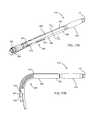
- the access devicemay include a sheath including a distal portion sized for introduction into a passage through tissue, a bendable section adjacent the distal section, and a proximal portion, e.g., including a pull tab, handle, or other feature for manipulating the access device.
- the sheathmay include an at least partially enclosed lumen extending between the proximal and distal portions.
- the bendable sectionmay be configured to curve to define an angle between the proximal and distal portions, e.g., up to ninety degrees (90°) without pinching or catching tissue.
- the length of the sheathmay be such that the distal portion may be disposed through a passage through tissue to access a body cavity or other target tissue region while the bendable section remains outside the patient's body.
- the bendable sectionmay be corrugated or may include a plurality of slots or other features to accommodate bending the bendable section.
- a method for brachytherapy treatment of tissuethat includes introducing a distal end of an access port device into a body cavity, expanding an expandable member on the distal end of the access port device within the cavity, advancing an elongate body carrying a plurality of elongate members through the access port device into the body cavity with the elongate members in a collapsed configuration, directing the elongate members to an expanded configuration within the body cavity to position the elongate members away from a central axis, and delivering radiation to a target location adjacent to the body cavity via the elongate members.
- the body cavityis a vaginal cavity and expanding the expandable member dilates the vaginal cavity.
- the methodfurther includes creating a tract through tissue to the body cavity.
- the methodmay include deflating the expandable member after directing the elongate members to the expanded configuration and before delivering the radiation.
- the methodmay further include directing the elongate members to the collapsed configuration, and withdrawing the elongate body from the body cavity.
- the methodmay include advancing a second elongate body carrying a second plurality of elongate members through the access port device into the body cavity with the second plurality of elongate members in a second collapsed configuration, directing the second plurality of elongate members to a second expanded configuration within the body cavity to position the second plurality of elongate members away from the central axis, and delivering a second phase of radiation to the target location adjacent to the body cavity.
- the methodmay include directing the second plurality of elongate members to the second collapsed configuration; and withdrawing the second elongate body from the body cavity.
- the expandable member of the access port devicemay be deflated, and the access port device may be withdrawn from the body cavity.
- a method for brachytherapy treatment of tissue within a patient's bodythat includes introducing a distal portion of a sheath into a passage through tissue to access a body cavity or other target tissue region, while a proximal portion of the sheath remains outside the patient's body.
- the sheathmay carry an expandable device, e.g., including an elongate shaft and a balloon or other expandable member, that may be introduced with the sheath with the expandable member collapsed.
- the expandable memberWhen the expandable member is disposed within the target tissue region, the expandable member may be expanded within the target tissue region, e.g., to dilate tissue surrounding a lumpectomy or other body cavity access using the sheath. Thereafter, the expandable member may be collapsed and the expandable device removed from the sheath, leaving the sheath within the passage to provide further access to the target tissue region.
- a distal portion of an applicatormay then be introduced through the sheath and into the target tissue region, e.g., for delivering brachytherapy treatment to the target tissue region.
- the distal portion of the applicatormay be expanded within target tissue region, and radiation may be deliver to the target tissue region via the applicator. If multiple treatments are needed, the applicator may be removed, leaving the sheath in place.
- the sheathmay include a bendable section that may be bent against the patient's skin to minimize a profile of the sheath while it remains in place.
- the sheathmay remain within the passage between treatment and, when additional treatment is needed, the bendable section may be bent away from the patient's skin to facilitate introducing an applicator into the target tissue region. After completing any desired treatments, the sheath may be withdrawn from the passage. Alternatively, if only a single treatment is needed, the sheath may be withdrawn after introducing an applicator through the sheath.
- a system for brachytherapy treatment of tissue adjacent a cavity within a bodyincludes an expandable brachytherapy applicator movable from a collapsed configuration to an expanded configuration, and an access port device sized for introduction into a body cavity and for receiving the brachytherapy applicator therein.
- the access port devicemay include an access port ring with an index and a plurality of grooves.
- the applicatormay also include an indexing bushing and a tab, wherein each of the grooves in the access port device is sized to receive the tab therein.
- the indexmay include a plurality of position labels and the indexing bushing may include a plurality of catheter labels, wherein the catheter labels match the position labels.
- the access port device of the systemmay be configured for insertion into a body cavity and for remaining in the body cavity between phases of treatment.
- the access port devicemay include an expandable member on a distal end of a multiple lumen shaft.
- the access port devicemay include a proximal end, a distal end sized for introduction into the body cavity, the expandable member on the distal end sized for delineating or dilating the tissue surrounding the body cavity, an access port ring on the proximal end, an inflation lumen extending between the proximal end and the expandable member, and a working lumen or channel extending between the proximal end and the expandable member for receiving the applicator therein.
- the applicator of the systemmay include an elongate core member, a distal tip at a distal end of the core member, an actuator axially movable relative to the core member, at least one of the actuator and the distal tip movable axially relative to the other of the actuator and the distal tip, and a plurality of expandable elongate members coupled to the actuator.
- the expandable membersIn the collapsed configuration, the expandable members may extend substantially parallel to the core member.
- the elongate membersmay be coupled to the distal end of the core member, and, in the expanded configuration, the expandable elongate members may define a pear shape, e.g., that bulges near the distal end of the core member and tapers towards the actuator.
- the elongate membersmay include unattached or free distal ends, and, in the expanded configuration, the distal ends may be directed transversely away from the core member.
- a systemfor brachytherapy treatment within a target tissue region of a patient's body accessed via a passage through tissue.
- the systemgenerally includes a sheath, an expandable device carried by the sheath, and an applicator for delivering radiation or other treatment to the target tissue region.
- the sheathmay include a distal portion sized for introduction into the passage through tissue, a proximal portion, and a bendable section therebetween.
- the sheathmay define an at least partially enclosed lumen extending between the proximal and distal portions
- the expandable devicemay include an elongate shaft that may be received in the lumen through the sheath and an expandable member disposed distally beyond the distal portion of the sheath, e.g., for dilating tissue surrounding a body cavity within the target tissue region.
- the sheathmay facilitate introducing the expandable device through the passage into the target tissue region, and the expandable device may be removable from the sheath, e.g., after expanding the expandable member to dilate tissue.
- the applicatorincludes a proximal end, a distal end sized for introduction through the lumen of the sheath, and one or more lumens or other pathways for delivering radiation or other treatment to the target tissue region.
- the applicatormay include a plurality of elongate members extending between the applicator proximal and distal ends that include pathways for receiving a source of radiation for delivering radiation to the target tissue region.
- the distal end of the applicatormay be expandable, e.g., by directing the elongate members from a collapsed configuration to an expanded configuration, to facilitate delivery of radiation according to a desired dose plan.
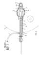
- FIG. 1is a side elevation view of an access port device including an expandable member in an expanded configuration.
- FIG. 1Ais a perspective view of a proximal end of the access port device of FIG. 1 .
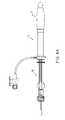
- FIG. 2is a cross-sectional side view of the access port device of FIG. 1 with the expandable member in the expanded configuration.
- FIGS. 3-6are partial cross-sectional side views of the access port device of FIGS. 1-2 , showing a method for brachytherapy treatment of breast tissue that includes using the access port device for introducing a brachytherapy applicator into the breast tissue.
- FIGS. 7A and 7Bare detailed perspective views of an index that may be provided on the access port device of FIGS. 1-2 , and an indexing bushing that may be provided on an applicator being introduced into the access port device.
- FIG. 8Ais a side view of an alternative embodiment of an apparatus for brachytherapy treatment including an access port device and applicator.
- FIG. 8Bis a side view of the apparatus of FIG. 8A showing a method for brachytherapy treatment of breast tissue.
- FIGS. 9A and 9Bare partial cross-sectional front views of a patient's body showing another embodiment of an access port device and an applicator in a collapsed configuration and an expanded configuration, respectively, introduced within a vaginal cavity.
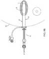
- FIG. 10is a partial cross-sectional side view of the patient's body and showing the access port device and applicator of FIGS. 9A and 9B .
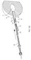
- FIG. 11Ais a perspective view of the applicator of FIGS. 9A , 9 B and 10 in the collapsed configuration.
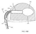
- FIG. 11Bis a detailed view of a distal end of the applicator of FIG. 11A .
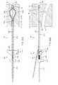
- FIG. 11Cis a side elevation view of the applicator of FIG. 11A .
- FIG. 11Dis a cross-sectional side view of the applicator taken along line 11 D- 11 D in FIG. 11C .
- FIG. 12Ais a perspective view of the applicator in FIGS. 9A , 9 B and 10 in the expanded configuration.
- FIG. 12Bis a detailed view of the distal end of the applicator of FIG. 12A .
- FIG. 12Cis a side elevation view of the applicator of FIG. 12A .
- FIG. 12Dis a cross-sectional side view of the applicator taken along line 12 D- 12 D in FIG. 12C .
- FIG. 13Ais a perspective view of still another embodiment of an applicator for brachytherapy treatment in a collapsed configuration.
- FIG. 13Bis a cross-sectional detail of a distal end of the applicator of FIG. 13A .
- FIG. 13Cis a side elevation view of the applicator of FIG. 13A .
- FIG. 13Dis a cross-sectional side view of the applicator taken along line 13 D- 13 D in FIG. 13C .
- FIG. 14Ais a perspective view of the applicator in FIGS. 13A-13D in an expanded configuration.
- FIG. 14Bis a cross-sectional detail of the distal end of the applicator of FIG. 14A .
- FIG. 14Cis a side elevation view of the applicator of FIG. 14A .
- FIG. 14Dis a cross-sectional side view of the applicator taken along line 14 D- 14 D in FIG. 14C .
- FIGS. 15A and 15Bare top and side views, respectively, of an exemplary embodiment of an access sheath for use in a brachytherapy system.
- FIG. 15Cis a side view of the access sheath of FIGS. 15A and 15B with a bendable section of the access sheath directed to a bent configuration.
- FIGS. 15D and 15Eare cross-sectional views of the access sheath taken along lines 15 D- 15 D and 15 E- 15 E, respectively, in FIG. 15A .
- FIGS. 16A and 16Bare top and side views, respectively, of another exemplary embodiment of an access sheath for use in a brachytherapy system.
- FIG. 16Cis a side view of the access sheath of FIGS. 16A and 16B with a bendable section directed to a bent configuration.
- FIGS. 16D and 16Eare cross-sectional views of the sheath taken along lines 16 D- 16 D and 16 E- 16 E, respectively, in FIG. 16A .
- FIG. 17Ais a perspective view of a brachytherapy system that includes an access sheath, such that shown in FIGS. 16A-16E , and an expandable device including a shaft received in a lumen of the access sheath.
- FIG. 17Bis a side view of the brachytherapy system of FIG. 17A with the sheath and consequently the shaft of the expandable device directed to a bent configuration.
- FIG. 17Cis a cross-sectional view of the brachytherapy system of FIG. 17A taken along line 17 C- 17 C.
- FIG. 18Ais a partial cross-sectional view of a patient's body showing a method for accessing a target tissue region within a breast using the brachytherapy system of FIGS. 17A-17C .
- FIG. 18Bshows an expandable member of the expandable device expanded to dilate tissue within the target tissue region and a bendable section of the access sheath directed to the bent configuration.
- FIG. 18Cshows the expandable device being removed from the access sheath after collapsing the expandable member.
- FIGS. 18D and 18Eshow an applicator being introduced through the access sheath until a distal portion of the applicator is disposed within the target tissue region.
- FIG. 18Fshows the distal portion of the applicator being expanded within the target tissue region.
- FIG. 18Gis a cross-sectional view of the applicator and access sheath of FIG. 18E taken along line 18 G- 18 G.
- FIG. 19Ais a perspective view of yet another embodiment of an applicator for brachytherapy treatment in a collapsed configuration.
- FIG. 19Bis a detail of a distal portion of the applicator of FIG. 19A in the collapsed configuration.
- FIG. 19Cis a perspective view of the applicator of FIG. 19A in an expanded configuration.
- FIG. 19Dis a detail of the distal portion of the applicator of FIG. 19C in the expanded configuration.
- FIGS. 20A and 20Bare top and side views, respectively, of the applicator of FIGS. 19A-19D in the expanded configuration and placed against a cervix within a vaginal cavity of a patient's body.
- FIGS. 1 , 1 A, and 2show an exemplary embodiment of an access port device 10 for expanding, dilating, and/or otherwise lining a body cavity or other target tissue region (not shown), e.g., to facilitate introduction of one or more therapeutic and/or diagnostic instruments (also not shown), e.g., a brachytherapy applicator, into the target tissue region.
- the access port device 10generally includes an elongate shaft 4 including a proximal end 22 , a distal end 24 sized for introduction through a passage into the body cavity, and an expandable member 5 extending from the distal end 24 to define an expandable distal region 20 .
- the expandable distal region 20may be in a collapsed configuration while the device 10 is inserted into the body cavity and then may be inflated or otherwise expanded to delineate or dilate the inner wall of the cavity and/or maintain the cavity geometry, e.g., during dosimetry planning.
- the expandable member 5may be formed from compliant or semi-compliant material such that, when the expandable member 5 is inflated, e.g., with saline or other inflation media, the expandable member 5 may grow to different volumes with different fill volumes of saline, yet the expandable member 5 material may be sufficiently rigid to provide substantial dilating pressure to the surrounding tissue.
- the expandable member 5may include a substantially rigid distal tip 18 to facilitate insertion of the distal region 20 through a tissue tract or other body passage into a body cavity. The size of the expandable member 5 may depend upon the size of the body cavity into which it is to be placed.
- the expandable member 5may have a length of between about three to six centimeters (3-6 cm), with the distal tip 18 having a length between about zero and one centimeter (0-1.0 cm), e.g., about seven millimeters (7 mm).
- the expandable member 5may have a maximum expanded diameter between about three to five centimeters (3-5 cm), a durometer or softness between about 85-95, e.g., about 90 Shore A, and/or a wall thickness of one to two thousandths of an inch (0.025-0.050 mm).
- the shaft 4may be a substantially rigid or semi-rigid tubular member, e.g., including an inflation lumen 7 and a working lumen or channel 8 .
- the inflation lumen 7may extend between the proximal and distal ends 22 , 24 of the shaft 4 such that the inflation lumen 7 communicates with an interior of the expandable member 5 .
- the inflation lumen 7communicates with a side port 9 on a handle or access port ring 3 to accommodate coupling a source of inflation media and/or vacuum (not shown) to the access port device 10 .
- a stopcock 1which may include a connector, e.g., a Luer lock connector, for connecting a source of inflation media and/or vacuum, e.g., a syringe of saline or other fluid, a vacuum line, and the like to deliver and/or remove inflation media from the interior of the expandable member 5 via the inflation lumen 7 .
- a connectore.g., a Luer lock connector
- a source of inflation media and/or vacuume.g., a syringe of saline or other fluid, a vacuum line, and the like to deliver and/or remove inflation media from the interior of the expandable member 5 via the inflation lumen 7 .
- the working channel 8may be sized to allow a brachytherapy applicator 16 or other device (not shown) to pass through the shaft 4 , e.g., from the proximal end 22 into the interior of the expandable member 5 , while preventing substantial fluid flow out of the working channel 8 , e.g., to prevent substantial deflation of the expandable member 5 .
- the working channel 8may include a one-way valve and/or a lubricious inner surface to accommodate receiving one or more devices through the shaft 4 into the expandable member 5 .
- the working channel 8may include one or more duck bill valves 6 (two shown adjacent one another) in order to keep the channel 8 substantially sealed during introduction and/or removal of the brachytherapy applicator and/or other devices.
- the working channel 8may be substantially larger than the inflation lumen 7 , e.g., such that the working channel 8 can accommodate receiving relatively larger devices therethrough.
- the working channel 8may have a diameter or other maximum cross-section between about six and twenty millimeters (6-20 mm), while the inflation lumen 7 may have a diameter or other maximum cross-section between about one and three millimeters (1-3 mm).
- the working channel 8 and inflation lumen 7may be coextruded when the shaft 4 is formed, e.g., such that the working channel 8 and inflation lumen 7 are disposed adjacent one another.
- the expandable member 5may be disposed on the distal end 24 of the shaft 4 in communication with the inflation lumen 7 and the working channel 8 .
- the expandable member 5 and the dual lumen shaft 4may be a single component, or may be formed from separate components that are attached together, e.g., using an interference fit, cooperating connectors, bonding with adhesives, sonic welding, and the like.
- the proximal end 22 of the shaft 4may include an access port ring, handle, or hub 3 .
- the ring 3may have a diameter sufficiently greater than a diameter of the shaft 4 so that when the distal end 20 of the access port device 10 is inserted through a passage into a body cavity, the ring 3 may remain outside of the body and may prevent the entire access port device 10 from entering the passage.
- the access port ring 3may have a relatively low profile, e.g., so that it is unobtrusive and patient discomfort is minimized.
- the overall length of the access port device 10may be such that, when the expandable member 5 is positioned within a body cavity and the shaft 4 is positioned within a passage through tissue communicating with the body cavity, the ring 3 may remain outside of the patient's body, e.g., such that a surface of the access port ring 3 is in contact with the skin or other outer surface of the patient's body.
- the shaft 4 and the ring 3may be a single component, e.g., integrally molded together, or may be formed from separate components that are attached together, e.g., using an interference fit, cooperating connectors, bonding with adhesives, sonic welding, and the like.
- the access port device 10may be introduced into the body cavity to facilitate the placement and/or exchange of one or more therapeutic and/or diagnostic instruments or other devices, e.g., an expandable brachytherapy applicator such as those described elsewhere herein and/or in co-pending application Ser. Nos. 10/658,518, filed Sep. 9, 2003 and published as U.S. Publication No. 2004/0116767, 11/276,851, filed Mar. 16, 2006 and published as U.S. Publication No. 2007/0106108, 11/554,731, filed Oct. 31, 2006 and published as U.S. Publication No. 2007/0167664, 11/557,747, filed Nov.
- an expandable brachytherapy applicatorsuch as those described elsewhere herein and/or in co-pending application Ser. Nos. 10/658,518, filed Sep. 9, 2003 and published as U.S. Publication No. 2004/0116767, 11/276,851, filed Mar. 16, 2006 and published as U.S. Publication No. 2007/0106108, 11/5
- the access port device 10may facilitate introduction of an expandable brachytherapy applicator 16 into a cavity 14 within a breast 90 .
- the breast 90may have a cavity 14 formed therein, e.g., a lumpectomy cavity created by removing cancerous tissue.
- the access port device 10may be introduced through a tissue tract 12 into the cavity 14 , as shown in FIG. 3 .
- the tissue tract 12may be created in advance, e.g., using a needle or other device (not shown). For example, the tissue tract 12 may be created during the lumpectomy procedure.
- the access port device 10may include a sharp distal tip (not shown) for piercing the tissue, similar to devices disclosed in the applications incorporated by reference elsewhere herein.
- the access port device 10may be inserted into the cavity 14 until the distal end 20 of the access port device 10 reaches the distal portion of the cavity 14 , the entire expandable member 5 is positioned within the cavity 14 , and/or the access port ring 3 is disposed adjacent to or contacts the outer surface of the breast 90 .
- the access port ring 3may remain on an outer surface of the breast 90 to provide access to the cavity 14 and to facilitate insertion and/or removal of the applicator 16 and/or other devices.
- the expandable member 5may then be inflated to contact the walls of the body cavity 14 .
- a syringe or other source of inflation media(not shown) may be coupled to the stopcock 1 , which may then be opened to allow delivery of inflation media to inflate the expandable member 5 .
- the expandable member 5may be further inflated to dilate the body cavity 14 . It will be appreciated that further inflation of the expandable member 5 may result in increased force between the expandable member 5 and the surface of the cavity 14 , which may substantially secure and/or otherwise limit undesirable movement of the expandable member 5 within the cavity 14 , thereby stabilizing the access port device 10 .
- the stopcock 1may be closed and the source of inflation media may be removed, if desired.
- the source of inflation mediamay be recoupled and the stopcock 1 reopened, if desired to reinflate and/or further expand the expandable member 5 or to collapse the expandable member 5 and remove the access port device 10 .
- the brachytherapy applicator 16may be inserted into the access port device 10 with the elongate members 26 in their collapsed configuration, e.g., until the distal end of the applicator 16 reaches the distal end 18 of the expandable member 5 .
- the inner surface of the working channel 8(not shown, see FIG. 2 ) may include a lubricious coating and/or other material to facilitate axial movement of devices therein, e.g., insertion and/or removal of the applicator 16 .
- the access port device 10 and the applicator 16may be coupled together prior to insertion into the cavity 14 , as shown in FIG. 8A .
- the applicator 16With the expandable member 5 and the applicator 16 in collapsed configurations, the applicator 16 may be positioned within the access port device 10 , and the access port device 10 and the applicator 16 may then be inserted through the tissue tract 12 into the cavity 14 at the same time, as shown in FIG. 8B .
- the expandable member 5may be inflated to the desired diameter as discussed above to achieve the configuration shown in FIG. 5 .
- the applicator 16may include a plurality of catheters, tubular members, or other elongate members 26 with pathways for receiving a source of radiation therealong, as described in greater detail in the applications incorporated by reference elsewhere herein.
- the catheters 26may be expanded to contact the inner surface of the expandable member 5 , as shown in FIG. 6 .
- the mechanism and method for expanding the catheters 26are described in greater detail in the applications incorporated by reference elsewhere herein.
- the expandable member 5may optionally be deflated, allowing the surrounding tissue to invaginate between the expanded catheters 26 , which, as described in the applications incorporated by reference elsewhere herein, may maintain the applicator 16 in place and prevent applicator rotation or axial movement.
- the applicator 16may be expanded without inflating the expandable member 5 .
- the expandable catheters 26may be expanded without first inflating the expandable member 5 . Expansion of the catheters 26 may cause simultaneous expansion of the expandable member 5 .
- one or more radiation sourcesmay be directed into lumens of the catheters 26 , and/or a center catheter 28 of the applicator 16 , e.g., according to a desired dose plan, to deliver radiation to the tissue surrounding the cavity 14 .
- radiationmay be applied while the catheters 26 are in the collapsed configuration.
- the catheters 26 and 28may define pathways for receiving radiation source(s), as described in the applications incorporated by reference elsewhere herein.
- the catheters 26may be collapsed, as shown in FIG. 5 , and the applicator 16 withdrawn from the cavity 14 , as shown in FIG. 4 .
- the access port device 10may then remain in place, as shown in FIG. 4 , e.g., between treatment phases or fractionations of treatment as in the case of brachytherapy treatment.
- the access port device 10may remain in place with the expandable member 5 partially deflated or fully deflated as shown in FIG. 3 . It will be appreciated that, with the expandable member 5 inflated as shown in FIG. 4 , the device 10 may be less likely to shift and more likely to maintain the desired position and cavity geometry.
- the applicator 16may be inserted and removed several times while the access port device 10 remains substantially in the desired position.
- maintaining the access port device 10 in the body cavitymay allow the applicator 16 to be easily removed between treatment fractionations and reintroduced (or another applicator, 16 to be introduced) as needed, which may provide for more accurate delivery of a desired dose plan throughout the several phases of treatment.
- the access port device 10may minimize exposure of the applicator 16 to bodily fluids, which may allow the applicator 16 to be easily cleaned, sterilized, and reused, if desired.
- the expandable member 5 of the access port device 10may be returned to its collapsed configuration, as shown in FIG. 3 and the access port device 10 removed from the breast 90 via the tissue tract 12 .
- a source of vacuum or aspiration(not shown) may be coupled to the stopcock 1 , which may be opened to allow the inflation media to be removed from the interior of the expandable member 5 .
- an open tubular member or other devicemay simply be inserted through the working channel 8 to open the valves 6 to allow the inflation media within the expandable member 5 to escape freely, thereby collapsing the expandable member 5 .
- the ability to decouple the access port device 10 and the applicator 16may allow for compensation of any rotational movement of the access port device 10 between treatment phases by simply re-indexing the applicator 16 back to the original dosimetry planning position.
- the access port ring 3 and the applicator 16may include an index 32 and an indexing bushing 34 , respectively, e.g., for indicating the rotational position of the catheters 26 relative to the surrounding cavity 14 .
- the index 32may include a plurality of position labels 35 and corresponding grooves 36 .
- the position labels 35are depicted as numbers, but may alternatively be letters, colors, symbols, and the like.
- the indexing bushing 34 on the applicator 16may include a plurality of catheter labels 33 corresponding to the plurality of position labels 35 .
- the catheter labels 33may match the position labels 35 .
- the catheter labels 33are depicted as numbers that match the position labels 35 , but may alternatively be letters, colors, symbols, and the like that correspond to the position labels 35 .
- the applicator 16may include a ring 40 adjacent the indexing bushing 34 , which includes a tab 38 fixedly attached thereto and sized for insertion into each of the grooves 36 .
- the ring 40may be fixed to the catheters 26 , e.g., to maintain the catheters 26 in their radial positions relative to each other, and the tab 38 may be aligned radially with one of the catheters 26 .
- a clinicianmay accurately determine the desired rotational position of the applicator 16 relative to the access port device 10 and, thus, to the body cavity 14 (not shown, see FIGS. 3-6 ), before the applicator 16 is inserted (or reinserted) into the access port device 10 , e.g., in order to ensure that the dose plan is accurately followed during a course of treatment. For example, if the access port device 10 rotates between treatment phases, it is possible to easily and accurately determine whether the applicator 16 should be rotated relative to the access port device 10 and into which of the grooves 36 the tab 38 should be inserted in order to maintain the proper orientation of the applicator 16 for the desired dose plan.
- the tab 38is inserted into the groove 36 corresponding to the position label 35 marked “2” when the applicator 16 is inserted into the access port device 10 .
- the tab 38 and groove 36prevent rotational movement of the applicator 16 relative to the access port device 10 once the tab 38 is received in the groove 36 .
- the clinicianmay easily determine that the tab 38 should be inserted into the groove 36 corresponding to the position label 35 marked “4” in order to compensate for the rotation of the device 10 and apply the same dose plan as was applied in the previous treatment phase.
- FIGS. 9A , 9 B, and 10another embodiment of a system 50 is shown that may be used for treating cervical and/or uterine cancer.
- the system 50includes a cavity access port device 52 and an applicator 54 , which may be similar to the access port device 10 and applicator 16 described above.
- the access port device 52may include an expandable member 55 , shown in FIG. 9A in a collapsed configuration and in FIGS. 9B and 10 in an expanded configuration.
- the access port device 52may be configured for positioning within a vaginal cavity 56 .
- the distal tip 60 of the access port device 52may be sized for ease of placement within the external os 58 of the cervix, e.g., to substantially seal the cervix, thereby limiting fluid flow through the os 58 during treatment.
- the expandable brachytherapy applicator 54may include a plurality of catheters or other elongate members 68 disposed around a center catheter 72 , generally similar to the previous applicator 10 .
- the applicator 54may include a distal tip 62 sized for positioning within the distal tip 60 of the access port device 52 , e.g., for ease of placement and localized delivery of radiation at the os and/or the cervix. Construction of the components of the applicator 54 may be generally similar to the applicators found in the applications incorporated by reference elsewhere herein.
- the expandable portions of the catheters 68may be coupled to an actuation hub 82 and a distal end of the center catheter 72 .
- the actuation hub 82 and/or the distal tip 62may be directed towards one another, thereby causing the catheters 68 to be subjected to an axially compressive force and to bow radially outwardly in a predetermined shape towards an expanded configuration.
- the predetermined shape of the expanded configurationmay conform to the tissue walls around the cervix in the vaginal cavity 56 .
- the actuation hub 82 and/or the distal tip 62may be directed apart from one another, thereby causing the catheters 68 to be pulled back radially inwardly towards a collapsed configuration. Further information regarding the mechanism and method for expanding and collapsing the catheters 68 may be found in the applications incorporated by reference elsewhere herein.
- the catheters 68may extend substantially parallel to the center catheter 72 .
- the distal ends of the catheters 68may have a slightly rounded shape where the distal tips of the catheters 68 curve slightly inward to attach to the center catheter 72 , as shown in FIGS. 9 A and 11 A- 11 D.
- the expandable portions of the catheters 68may be biased towards the cervix and/or uterus so that radiation applied through the catheters 68 may be preferentially directed distally towards the cervix and/or uterus, and away from surrounding, healthy tissue.
- the expanded catheters 68may form a pear shape that bulges near the distal tip 62 of the applicator 54 and tapers towards the actuation hub 82 , as depicted in FIGS. 9B , 10 , and 12 A- 12 D.
- the catheters 68may expand radially outwardly into the pear shape, e.g., due to support members attached thereto and/or due to the configuration of the expandable catheters 68 , as disclosed in the applications incorporated by reference herein.
- the catheters 68may include one or more support members 66 , e.g., extending at least partially along the expandable portions of the catheters 68 .
- the support members 66may be elongate strips of material, e.g., metal, such as stainless steel or Nitinol, plastic, or composite material, that may be elastically deflected during use of the applicator 54 , e.g., when the catheters 68 are directed between the collapsed and expanded configurations.
- the catheters 68may have asymmetrical cross-sections providing a moment of inertia that biases the catheters 68 to expand radially outwardly in the predetermined manner, as disclosed in the applications incorporated by reference herein.
- the catheters 68may be arranged asymmetrically around the center catheter 72 .
- the applicator 54may include three catheters 68 positioned substantially on one side of a plane extending parallel to a central longitudinal axis 63 defined by the center catheter 72 .
- the catheters 68may lie within or above a plane extending along the longitudinal axis 63 , thereby providing an asymmetrical arrangement.
- the catheters 68may be oriented away from the rectum during use, e.g., to protect rectal tissue 70 from radiation exposure.
- the access port device 52 and the applicator 54may be introduced into the vaginal cavity 56 (successively or simultaneously, similar to the methods described above) until the distal tip 60 of the access port device 52 and the distal tip 62 of the applicator 54 are positioned within the external os 58 of the cervix, as shown in FIG. 9A .
- the access port device 52may be inserted first with the expandable member 55 collapsed, and the applicator 54 may be inserted into the access portion device 52 with the expandable member 55 remaining collapsed.
- the applicator 54may be inserted into the access portion device 52 outside the patient's body, and the access port device 52 and applicator 54 may be inserted at the same time.
- the expandable member 55 of the access port device 52may then be inflated.
- the access port device 52may be inserted and the expandable member 55 inflated before inserting the applicator 54 .
- the expandable member 55When the expandable member 55 is inflated, the vaginal cavity 56 may be dilated, e.g., to push healthy, non-target tissue away from the applicator 54 , which may protect the healthy non-target tissue from substantial radiation exposure during treatment. This may be particularly useful in cervical and/or uterine cancer treatment so that sensitive tissue, e.g., the vaginal walls and rectum, may be protected from substantial radiation exposure and damage.
- the expandable catheters 68 of the applicator 54may be directed to the expanded configuration, as shown in FIGS. 9B and 10 , e.g., by directing the actuation hub 82 towards the distal tip 62 .
- the method for expanding the catheters 68may be substantially similar to the method for expanding the catheters 26 of the applicator 16 (e.g., as shown in FIGS. 5-7B ), which method is discussed in greater detail in the applications incorporated by reference herein.
- radiationmay be delivered to the target location adjacent to the body cavity.
- radiationmay be delivered to tissue, e.g., to the cervix and/or the uterus (not shown), adjacent to the vaginal cavity 56 .
- the lumens of the catheters 68 and 72may define pathways for receiving radiation source(s).
- One or more radiation sourcesmay be directed into the lumens of the catheters 68 and 72 to deliver radiation to the tissue surrounding the cavity 56 , which, due to the biased shape of the expanded applicator 54 , is preferentially delivered to the cervix and/or the uterus.
- one or more HDR sourcesmay be delivered sequentially into the expandable catheters 68 and/or the center catheter 72 , as described in the applications incorporated by reference herein.
- an HDR sourcemay be introduced into a first expandable catheter 68 , advanced to a first position, and maintained at the first position for a predetermined time.
- the HDR sourcemay then be advanced and/or retracted to a second position, and maintained there for a predetermined time, etc.
- the HDR sourcemay then be removed from the first expandable catheter 68 , and then introduced sequentially into each of the other expandable catheters 68 in a similar manner.
- one or more radiation sourcesmay be preloaded or secured within the expandable catheters 68 before introduction into the cavity 56 . Additional information on use of the applicator 54 may be found in the applications incorporated by reference herein.
- FIGS. 13A-14Danother exemplary embodiment of an expandable brachytherapy applicator 150 is shown, which includes a plurality of expandable catheters 168 disposed around a center catheter 172 , which may be constructed similar to the applicators described above and disclosed in the applications incorporated by reference elsewhere herein.
- the applicator 150may also include a center catheter handle 152 fixedly coupled to the center catheter 172 , a catheter ring 154 for maintaining the positions of the expandable catheters 168 relative to one another and relative to the center catheter 172 , an actuator 182 , a catheter sleeve 184 , and a distal tip 162 .
- FIGS. 13A-14Danother exemplary embodiment of an expandable brachytherapy applicator 150 is shown, which includes a plurality of expandable catheters 168 disposed around a center catheter 172 , which may be constructed similar to the applicators described above and disclosed in the applications incorporated by reference elsewhere herein.
- the applicator 150may also include a center
- the applicator 150is shown in a collapsed configuration in which distal ends 170 of the catheters 168 are constrained within the catheter sleeve 184 .
- the applicator 150is shown in an expanded configuration in which the distal ends 170 are exposed or otherwise deployed from the catheter sleeve 184 and expand transversely away from the center catheter 172 .
- the actuator 182may be fixedly coupled to the expandable catheters 168 and slidably coupled to the center catheter 172 .
- the center catheter 172may slide axially relative to the actuator 182 , e.g., through a central opening (not shown) in the actuator 182 .
- the applicator 150may further include an expansion tool (not shown) that may be selectively coupled to the actuator 182 from a proximal end of the applicator 150 , e.g., for operating the actuator 182 to direct the distal ends 170 of the catheters 168 between the collapsed and expanded configurations.
- the expansion toolmay be removably coupled to the actuator 182 and/or the proximal end of the applicator 150 , similar to expansion tools disclosed in the applications incorporated by reference elsewhere herein.
- the catheter sleeve 184 and the distal tip 162may be coupled or integrally formed together, e.g., with a tapered transition 164 therebetween.
- the tapered transition 164may include one or more openings 186 therein, e.g., a plurality of openings 186 sized for receiving the distal ends 170 of respective catheters 168 therethrough.
- the proximal end of the catheter sleeve 184may include an enlarged shoulder portion 188 , which may be attached to or integrally formed with the catheter sleeve 184 .
- distal tip 162 , tapered transition 164 , catheter sleeve 184 , and shoulder 188may be integrally molded as a single component, or may be formed from separate components that are attached together, e.g., using an interference fit, cooperating connectors, bonding using adhesive, sonic welding, and the like.
- the expandable catheters 168may be substantially parallel to the center catheter 172 and may be positioned within the catheter sleeve 184 with the distal ends 170 of the catheters 168 adjacent to the openings 186 in the tapered transition 164 of the catheter sleeve 184 .
- the center catheter 172may be remain positioned within the sleeve 184 while the distal ends 170 of the catheters 168 may extend out of the openings 186 in the catheter sleeve 184 .
- the distal ends 170 of the catheters 168may be unattached and configured to expand transversely or radially outwardly away from the center catheter 172 in a predetermined manner upon being deployed from the catheter sleeve 184 .
- the distal ends 170 of the catheters 168may be biased to curve radially outwardly into the expanded configuration, e.g., due to support members 166 attached thereto and/or due to the construction of the catheters 168 themselves, as described in the applications incorporated by reference elsewhere herein.
- the catheters 168may include one or more support members 166 , e.g., extending at least partially along the expandable distal ends 170 of the catheters 168 .
- the support members 166may be elongate strips of material, e.g., metal, such as stainless steel or Nitinol, plastic, or composite material, that may be elastically deflected during use of the applicator 150 , e.g., when the distal ends 170 are directed between the collapsed and expanded configurations.
- the catheters 168may have asymmetrical cross-sections providing a moment of inertia that biases the catheters 168 to bend or curve radially outwardly in the predetermined manner, as disclosed in the applications incorporated by reference herein.
- a usermay grasp the center catheter handle 152 to maintain the position of the center catheter 172 while simultaneously directing the actuator 182 distally towards the catheter sleeve 184 until the actuator 182 contacts the enlarged shoulder portion 188 of the sleeve 184 , as shown in FIGS. 14A-14D .
- Distal movement of the actuator 182 away from the handle 152may cause distal movement of the expandable catheters 168 relative to the center catheter 172 .
- the expandable catheters 168are directed distally, the unattached distal ends 170 of the catheters 168 may be deployed distally out of the openings 186 in the sleeve 184 .
- the distal tips 170 of the catheters 168may be biased towards an outwardly curved shape.
- the distal ends 170may bend radially outwardly away from the center catheter 172 .
- a usermay grasp the handle 152 and retract the actuator 182 proximally towards the handle 152 .
- Proximal movement of the actuator 182may cause the catheters 168 to retract proximally back into the catheter sleeve 184 .
- the sleeve 184may force the distal ends 170 back into the collapsed, substantially parallel configuration shown in FIGS. 13A-13D .
- Movement of the actuator 182may be controlled by an expansion tool removably coupled to the proximal end of the applicator 150 , as discussed above.
- the applicator 150may be part of a system, e.g., including a tubular delivery device, such as a catheter, cannula, trocar, obturator, and/or needle (not shown), for introducing the applicator 150 into a target location, e.g., as described in the applications incorporated by reference elsewhere herein.
- a tubular delivery devicesuch as a catheter, cannula, trocar, obturator, and/or needle (not shown)
- the applicator 150may be part of a system that may include an access port device, e.g., similar to the access port device 10 in FIGS. 1 and 2 and/or to the access port device 52 in FIGS. 9A , 9 B and 10 .
- a method for using such a systemmay be substantially similar to the method for using the system 50 depicted in FIGS. 9A , 9 B and 10 .
- an access port device(not shown) may be introduced into a vaginal cavity with an expandable member on a distal end thereof in a collapsed configuration.
- the applicator 150may be positioned within the access port device before or after introducing the access port device into the vaginal cavity, e.g., for simultaneous or successive introduction of the access port device and the applicator 150 .
- the applicator 150may be introduced into the vaginal cavity after the access port device has been fully inserted, and before or after the expandable member has been inflated, as described above.
- the actuator 182may be directed distally towards the catheter sleeve 184 , thereby pushing the catheters 168 out of the catheter sleeve 184 and causing the distal ends 170 to expand transversely away from the center catheter 172 .
- the distal ends 170may curve outwardly such that the ends abut (through the access port device) the cervix of the patient being treated without substantial contact with the vaginal walls.
- radiationmay be applied through the catheters 168 and 172 similar to the previous embodiments. Due to the outwardly curved shape of the expanded distal ends 170 of the catheters 168 , radiation may be directed towards the target tissue and away from healthy tissue.
- the target tissuemay be cervical tissue and/or uterine tissue.
- the distal ends 170 of the catheters 168may be retracted proximally into the catheter sleeve 184 by pulling the actuator 182 proximally away from the sleeve 184 .
- the collapsed applicator 150may then be withdrawn from the access port device.
- the access port devicemay subsequently be deflated and withdrawn from the vaginal cavity immediately or after multiple treatments with the same or different applicator, similar to the previous embodiments.
- FIGS. 19A-20Banother exemplary embodiment of an expandable brachytherapy applicator 250 is shown that includes a plurality of expandable catheters 268 , e.g., two catheters 268 , disposed adjacent a center catheter 272 .
- the applicator 250may be constructed generally similar to the other embodiments described herein and in the applications incorporated by reference above, e.g., using similar materials and methods.
- the applicator 250includes an expandable distal portion 254 , which may be introduced into a body cavity or other target tissue region, and a proximal portion 252 , which may extend from the target tissue region out of a patient's body during use, e.g., to allow one or more sources of radiation (not shown) to be introduced into the catheters 268 , 272 , similar to the previous embodiments.
- the applicator 250includes a distal tip 262 sized for positioning within an os 58 of a cervix and/or within a tip of an access device (not shown), e.g., similar to the previous embodiments.
- distal ends of the catheters 268 , 272may be coupled to the distal tip 262 and/or to each other, e.g., by interference fit and/or connectors (not shown) within the distal tip 262 , by bonding with adhesives, sonic welding, fusing, and the like.
- the expandable catheters 268may be coupled to a hub 282 , while the center catheter 272 may be slidable through or otherwise movable relative to the hub 282 .
- the hub 282 and/or the distal tip 262may be directed towards one another, thereby causing expandable portions 268 a of the expandable catheters 268 (i.e., between the hub 282 and distal tip 262 ) to be subjected to an axially compressive stress.
- This stresscauses the expandable portions 268 a to bow radially outwardly from a collapsed, e.g., axial, configuration (shown in FIGS. 19A and 19B ) to an expanded configuration (shown in FIGS. 19C and 19D ).
- the hub 282 and the distal tip 262may be directed apart from one another, thereby causing the expandable portions 268 of the catheters 268 to be pulled back radially inwardly towards the collapsed configuration.
- the expandable portions 268 a of the catheters 268may extend substantially parallel to the center catheter 272 .
- the expandable portions 268 a of the catheters 268may expand away from one another substantially within a plane, i.e. to define a substantially planar shape in the expanded configuration.
- the central catheter 272may be offset below the plane defined by the catheters 268 , e.g., such that the catheters 268 are offset asymmetrically from a central axis of the central catheter 272 , similar to the previous embodiments.
- At least the expandable portions 268 a of the catheters 268may include one or more support members 266 , e.g., attached to or otherwise extending at least partially along the expandable portions 268 a .
- the support members 266may bias the expandable portions 268 a of the catheters 268 to remain substantially within the desired plane during expansion and contraction with minimal lateral movement out of the plane.
- the support members 266may be elongate strips of material, e.g., metal, such as stainless steel or Nitinol, plastic, or composite material, that may be elastically deflected during use of the applicator 250 , e.g., when the catheters 268 are directed between the collapsed and expanded configurations.
- materiale.g., metal, such as stainless steel or Nitinol, plastic, or composite material
- the applicator 250includes an actuator 280 , e.g., on the proximal portion 252 of the applicator 250 , for directing the expandable portions 268 a of the catheters 268 between the collapsed and expanded configurations.
- the actuator 280may include a handle 284 coupled to the hub 282 , e.g., by shaft 273 , and a plunger 286 coupled to the center catheter 272 .
- the shaft 273may be substantially rigid and/or axially incompressible (e.g., but bendable) such that the distance between the hub 282 and the handle 284 remains substantially fixed.
- the shaft 273may be a tubular body, e.g., including a lumen for slidably receiving the central catheter 272 therethrough (not shown).
- the central catheter 272may slide or otherwise move adjacent to the shaft 273 rather than through the shaft 273 .
- the plunger 286may be movable relative to the handle 284 , e.g., slidable axially between a first or distal position (shown in FIG. 19A ) and a second or proximal position (shown in FIG. 19C ), to move the center catheter 272 relative to the shaft 273 and consequently relative to the expandable catheters 268 .
- the plunger 286may include a piston or other elongate member 287 that is slidable a predetermined distance into and out of the handle 284 , thereby limiting motion of the plunger 286 between the first and second positions.
- the plunger 286may be biased to one of the first and second positions, e.g., by a spring 288 between the plunger 286 and handle 284 .
- the spring 288may be a compression spring located between the handle 284 and plunger 286 (e.g., on a shaft, not shown), although alternatively, the spring may be located inside the handle 284 (not shown), e.g., coupled to the piston 287 .
- the handle 284may include a locking pin 285 , which may be selectively engaged with the plunger 286 to selectively lock the plunger 286 in a desired position.
- the locking pin 285may create an interference fit with the piston 287 when engaged, or the locking pin 285 may be received in one or more apertures (not shown) in the piston 287 to lock the plunger 286 . It will be appreciated that other locking mechanisms may be provided between the handle 284 and plunger 286 , as desired.
- the spring 288may bias the plunger 286 to the second position, where the expandable catheters 268 are in the expanded configuration.
- the bias of the spring 288may be overcome by directing the plunger 286 to the first position and then engaging the locking pin 285 to lock the plunger 286 in the first position, as shown in FIG. 19A .
- the locking pin 285may be engaged in the second position (or any other intermediate position, if desired), e.g., to prevent inadvertent collapse of the expandable catheters 268 during use.
- the applicator 250may be introduced into a vaginal cavity 56 (or a lumpectomy cavity or other target tissue region) with the catheters 268 in the collapsed condition, similar to the other embodiments herein.
- the applicator 250may be introduced with or through an access device (successively or simultaneously), similar to the other embodiments herein. As shown, the applicator 250 may be introduced until the distal tip 262 is positioned within the external os 58 .
- the applicator 250may be manipulated to orient the expandable portions 268 a of the catheters 268 in a desired orientation. For example, similar to the previous embodiments, it may desirable to orient the expandable portions 268 a towards the cervix and/or vaginal wall and/or away from the rectum 70 or other regions of the target tissue region. As best seen in FIG. 20B , for example, the applicator 250 may be rotated to orient the expandable catheters 268 away from the rectum 70 , i.e., with the center catheter 272 disposed between the expandable catheters 268 and the rectum 70 . Thus, the plane of expansion of the expandable portions 268 a of the catheters 268 may be oriented laterally relative to the patient's body and not anteriorly or posteriorly.
- the expandable portions 268 a of the catheters 268may be directed to the expanded configuration, as shown in FIGS. 20A and 20B .
- the applicator 250may be actuated simply by releasing the locking pin 285 .
- the spring 288may then bias the plunger 286 and consequently the center catheter 272 to move proximally relative to the expandable catheters 268 to axially compress and expand the expandable portions 268 a .
- the distal tip 262 of the applicator 250may remain substantially stationary, e.g., within the os 58 of the cervix, which may facilitate stabilization of the applicator 250 during use.
- radiationmay be delivered to the tissue adjacent the applicator 250 , e.g., to the cervix and/or the uterus adjacent to the vaginal cavity 56 .
- the lumens of the catheters 268 and 272may define pathways for receiving radiation source(s).
- One or more radiation sourcesmay be directed into the lumens of the catheters 268 and 272 to deliver radiation to the tissue surrounding the cavity 56 in accordance with a desired dose plan.
- the applicator 250may be returned to the collapsed configuration, e.g., by advancing the plunger 286 and then engaging the locking pin 285 .
- the collapsed applicator 250may then be removed from the vaginal cavity 56 and patient's body. If an access device remains within the vaginal cavity 56 , another applicator (or the same applicator) may be introduced using the access device for one or more subsequent treatments.
- other access devicesmay be provided, e.g., for expanding, dilating, creating, and/or otherwise lining a tissue tract or other passage through tissue, e.g., that leads to a body cavity or other target treatment location, to facilitate introduction of one or more instruments.
- an exemplary embodiment of such an access sheath 200is shown that generally includes a distal portion 202 sized for introduction into a passage through tissue, a bendable intermediate section 204 , and a proximal portion 206 .
- the access sheath 200may include a wall that at least partially defines a lumen 212 that extends between the proximal and distal portions 206 , 202 of the access sheath 200 .
- the proximal portion 206 of the access sheath 200may include a pull tab, handle, or other feature, which may facilitate manipulation, e.g., advancing, retracting, and/or bending, the access sheath 200 during use.
- the passage 212 of the access sheath 200is defined by a generally “C” shaped wall that includes longitudinal edges 211 that define a gap 208 .
- the wallmay be biased to the “C” shape, yet resiliently deflectable to allow the longitudinal edges 211 to separate or otherwise move, e.g., to increase a diameter of the passage 212 , a width of the gap 208 , and/or otherwise adjust a shape of the access sheath 200 .
- the access sheath 200may accommodate receiving one or more instruments (not shown) through the gap 208 and/or the access sheath 200 may be easily removable from around an instrument received within the passage 212 .
- the bendable section 204may include a plurality of ridges or corrugations 210 that extend partially around the circumference of the access sheath 200 .
- the ridges 210may impart increased flexibility to the bendable section 204 relative to the distal and proximal portions 202 , 206 of the access sheath 200 , e.g., to allow the bendable section 204 to curve or otherwise bend in a desired manner.
- the ridges 210may protrude outwardly from an outer surface of the access sheath 200 and/or may be hollow so as to form troughs 214 on an inner surface of the sheath 200 .
- the number, size, and/or spacing of the ridges 210may be selected to make the bendable section 204 flexible enough to bend to a desired degree, e.g., to at least approximately a ninety degree (90°) angle between the proximal and distal portions 206 , 202 of the access sheath 200 , as illustrated in FIG. 15C .
- Other angles greater or less than ninety degrees (90°)may also be possible, if desired, depending upon the material and construction of the ridges 210 or other features of the bendable section 204 .
- the access sheath 200may include other features that impart increased flexibility to the bendable section 204 .
- FIGS. 16A-16Eanother exemplary embodiment of an access sheath 300 is shown that includes a bendable section 304 including a plurality of slots 310 cut or otherwise formed through the wall of the access sheath 300 for increasing the flexibility of the bendable section 304 relative to the proximal and distal sections of the sheath 300 . Similar to the access sheath 200 in FIGS.
- the access sheath 300generally includes a semi-rigid distal portion 302 , a proximal portion 306 including a pull tab, a lumen 312 extending therebetween, and longitudinal edges 311 defining a continuous gap 308 that extends between the proximal and distal portions 306 , 302 .
- the access sheath 300may include a lubricious coating and/or other material, e.g., on an inner surface thereof to facilitate introduction of one or more instruments through the lumen 312 and/or on an outer surface thereof to facilitate advancement through tissue with minimal resistance.
- the lumen 312 of the sheath 300may be sized for slidably receiving one or more instruments therethrough, e.g., an expandable dilation device 410 , such as that shown in FIGS. 17A-17C , an access port device (not shown), such as that shown in FIGS. 1-2 , and/or an applicator (also not shown), such as any of those described herein or in the references incorporated by reference herein.
- the gap 308 in the sheath 300may widen, thereby expanding the diameter of the sheath 300 to accommodate the instrument.
- an expandable dilation device 410is shown that may be carried by or otherwise used in conjunction with the access sheath 300 .
- the expandable device 410includes an elongated shaft 422 including a proximal end 424 , a distal end 426 , and a balloon or other expandable member 420 on the distal end 426 .
- the expandable member 420may be constructed similar to the expandable member 5 on the access port device 10 shown in FIGS. 1-2 and described further elsewhere herein, e.g., formed from compliant or semi-compliant material expandable between collapsed and expanded conditions and terminating in a distal tip 421 .
- the shaft 422may also be constructed similar to the shaft 4 of the access port device 10 , except that the shaft 422 may not include the ring 3 and working channel 8 . Instead, the shaft 422 may include a single lumen (not shown) extending from a connector 425 on the proximal end 424 , e.g., a Luer lock connector, to an interior of the expandable member 420 .
- a connector 425 on the proximal end 424e.g., a Luer lock connector
- the shaft 422includes one or more guide elements 402 (two shown) for cooperating with the longitudinal edges 311 of the access sheath 300 , e.g., to maintain the expandable device 410 in a desired orientation relative to the access sheath 300 .
- the guide element(s) 402may allow the shaft 422 of the expandable device 410 to be received within the lumen 312 of the access sheath 300 in a predetermined angular orientation, yet allow axial movement of the shaft 422 relative to the access sheath 300 .
- the entire assembly, including the expandable device 410 and the access sheath 300may be sufficiently flexible to bend, if desired, e.g., up to a ninety degree (90°) angle.
- the access sheath 300 and expandable device 410may be used during brachytherapy treatment of tissue within a target tissue region, e.g., also involving a brachytherapy treatment device, such as applicator 416 shown in FIGS. 18E and 18F . It will be appreciated, however, that the methods described herein may apply to using any of the brachytherapy treatment devices described elsewhere herein and in the references incorporated by reference herein, and should not be limited to the particular applicator 416 shown.
- the expandable device 410 and access sheath 300may be placed through a passage through tissue 12 into a body cavity or other target tissue region 14 , e.g., a lumpectomy cavity within a breast 90 , a vaginal cavity (not shown), and the like.
- the sheath 300may be introduced through the passage 12 until the distal portion 302 communicates with the body cavity 14 .
- the passage 12may be created, although alternatively, the passage 12 may already exist, e.g., from a lumpectomy or other procedure.
- the access sheath 300may be introduced into the passage 12 , e.g., over a needle, dilator, and/or other device.
- the access sheath 300may be compressed to a smaller diameter, e.g., by at least partially overlapping the longitudinal edges 311 , to facilitate introduction into the passage 12 .
- the expandable device 410may be introduced into the lumen 312 of the access sheath 300 and advanced until the expandable member 420 is disposed within the body cavity 14 .
- the guide element(s) 402may be aligned with the longitudinal edges 311 of the access sheath 300 and the expandable device 410 may be advanced through the lumen 312 of the access sheath 300 until the expandable member 420 is positioned within the body cavity 14 .
- the expandable device 410may be advanced until the distal tip 421 of the expandable member 420 abuts a distal end of the body cavity 14 and/or until the entire expandable member 420 is positioned within the body cavity 14 , as shown in FIG. 18A . If desired, the position of the expandable member 420 may be confirmed, e.g., using fluoroscopy, ultrasound, or other imaging, e.g., by providing markers (not shown) on the distal tip 421 and/or elsewhere on the expandable member 420 or expandable device 410 .
- the expandable device 410may be received within the access sheath 300 before being introduced into the passage 12 and/or body cavity 14 .
- the expandable device 410may be inserted into the lumen 312 of the access sheath 300 , e.g., until the expandable member 420 is disposed beyond the distal portion 302 of the access sheath 300 .
- the resulting assembly including the sheath 300 and the expandable device 410may be advanced into the passage 12 together until the distal portion 302 of the sheath 300 is disposed adjacent the body cavity 14 and/or the expandable member 420 is disposed within the body cavity 14 .
- the access sheath 300 and expandable device 410may be advanced until the distal tip 421 of the expandable member 420 abuts a distal end of the body cavity 14 and/or until the entire expandable member 420 is positioned within the body cavity 14 , also as shown in FIG. 18A , and optionally using external imaging.
- the length of the access sheath 300is such that the bendable section 304 of the access sheath 300 remains outside of the patient's body when the distal portion 302 of the access sheath 300 is advanced sufficiently to provide access to the body lumen 14 .
- the access sheath 300may remain in place for an indefinite period of time, e.g., after removing the expandable device 410 and/or the applicator 416 or leaving the expandable device 410 and/or applicator 416 within the body cavity 14 . In these situations, the bendable section 304 of the access sheath 300 may be bent to place the external components against or immediate adjacent the breast 90 or the patient's skin if used at other locations.
- the bendable section 304 of the sheath 300may be bent or folded against the outside of the breast 90 to minimize contact with the external components, interference of the external components to other activities, and/or discomfort by the patient.
- the expandable member 420may be expanded within the body cavity 14 , e.g., to engage and/or dilate surrounding tissue, similar to the access port device described above.
- the expandable member 420may also be introduced into the access sheath 300 and body cavity after treatment, e.g., after removing the applicator 416 , as described further below, to substantially seal the passage 12 between treatments.
- the expandable member 420may be collapsed, and the expandable device 410 may be withdrawn from the body cavity 14 and access sheath 300 .
- the access sheath 300may be returned to a straightened configuration, e.g., to facilitate removal of the expandable device 410 .
- the access sheath 300may remain in the bent configuration and the expandable device 410 may be removed by separating the longitudinal edges 311 of the access sheath 300 , i.e., to widen the gap 308 sufficiently to accommodate removal of the expandable device 410 .
- an applicator 416may be inserted through the access sheath 300 and into the body cavity 14 .
- the access sheath 300may be in the straightened configuration to facilitate introducing the applicator 416 through the lumen 312 of the access sheath 300 .
- the applicator 416may be advanced through the access sheath 300 such that the longitudinal edges 311 of the access sheath 300 slidably engage catheters 412 of the applicator 416 , as shown in FIG. 18G .
- the access sheath 300may function to hold the catheters 412 of the applicator 416 together during introduction of the applicator 416 and/or maintain the applicator 416 in a desired angular orientation during introduction through the access sheath 300 .
- the applicator 416When an expandable distal portion of the applicator 416 is positioned within the body cavity 14 , the applicator 416 may be expanded, as shown in FIG. 18F .
- the catheters 412 of the applicator 416may remain engaged with the longitudinal edges 311 of the access sheath 300 , thereby minimizing movement of the catheters 412 during treatment.
- the access sheath 300may be removed from around the applicator 416 .
- a pull tab on the proximal end 306 of the access sheath 300may be pulled, thereby separating the longitudinal edges and opening the gap 308 in access sheath 300 sufficiently to remove the access sheath 300 without substantially disturbing the applicator 416 .
- radiationmay be delivered to tissue adjacent the body cavity 14 , e.g., similar to embodiments and methods described elsewhere herein and in the references incorporated by reference.
- the applicator 416may be bent in conjunction with the access sheath 300 if the access sheath 300 remains.
- the applicator 416may be removed from the access sheath 300 , and the expandable device 410 may be reintroduced through the access sheath 300 , as described above.
- the applicator 416 and/or access sheath 300may be removed and the patient treated using known methods for closing the passage 12 .
Landscapes
- Health & Medical Sciences (AREA)
- Engineering & Computer Science (AREA)
- Biomedical Technology (AREA)
- Nuclear Medicine, Radiotherapy & Molecular Imaging (AREA)
- Pathology (AREA)
- Radiology & Medical Imaging (AREA)
- Life Sciences & Earth Sciences (AREA)
- Animal Behavior & Ethology (AREA)
- General Health & Medical Sciences (AREA)
- Public Health (AREA)
- Veterinary Medicine (AREA)
- Surgery (AREA)
- Heart & Thoracic Surgery (AREA)
- Radiation-Therapy Devices (AREA)
Abstract
Description
Claims (24)
Priority Applications (1)
| Application Number | Priority Date | Filing Date | Title |
|---|---|---|---|
| US12/543,463US8475353B2 (en) | 2008-08-18 | 2009-08-18 | Brachytherapy apparatus, systems, and methods for using them |
Applications Claiming Priority (2)
| Application Number | Priority Date | Filing Date | Title |
|---|---|---|---|
| US8985508P | 2008-08-18 | 2008-08-18 | |
| US12/543,463US8475353B2 (en) | 2008-08-18 | 2009-08-18 | Brachytherapy apparatus, systems, and methods for using them |
Publications (2)
| Publication Number | Publication Date |
|---|---|
| US20100048977A1 US20100048977A1 (en) | 2010-02-25 |
| US8475353B2true US8475353B2 (en) | 2013-07-02 |
Family
ID=41337091
Family Applications (2)
| Application Number | Title | Priority Date | Filing Date |
|---|---|---|---|
| US12/543,469Active2031-01-11US8636635B2 (en) | 2008-08-18 | 2009-08-18 | Brachytherapy apparatus, systems, and methods for using them |
| US12/543,463Active2031-02-26US8475353B2 (en) | 2008-08-18 | 2009-08-18 | Brachytherapy apparatus, systems, and methods for using them |
Family Applications Before (1)
| Application Number | Title | Priority Date | Filing Date |
|---|---|---|---|
| US12/543,469Active2031-01-11US8636635B2 (en) | 2008-08-18 | 2009-08-18 | Brachytherapy apparatus, systems, and methods for using them |
Country Status (2)
| Country | Link |
|---|---|
| US (2) | US8636635B2 (en) |
| WO (1) | WO2010022103A1 (en) |
Cited By (3)
| Publication number | Priority date | Publication date | Assignee | Title |
|---|---|---|---|---|
| WO2020167761A1 (en)* | 2019-02-11 | 2020-08-20 | University Of Iowa Research Foundation | Re-activatable radiation source for brachytherapy |
| US11541251B2 (en) | 2018-09-26 | 2023-01-03 | University Of Iowa Research Foundation | Apparatus and method for rotating shield brachytherapy |
| WO2024039394A1 (en)* | 2022-08-16 | 2024-02-22 | Bard Peripheral Vascular, Inc. | Radiation spacer devices, delivery systems, and methods for the prevention of collateral radiation |
Families Citing this family (43)
| Publication number | Priority date | Publication date | Assignee | Title |
|---|---|---|---|---|
| US6770080B2 (en) | 2001-04-26 | 2004-08-03 | Fenestra Medical, Inc. | Mechanically registered videoscopic myringotomy/tympanostomy tube placement system |
| US7662082B2 (en) | 2004-11-05 | 2010-02-16 | Theragenics Corporation | Expandable brachytherapy device |
| US7465268B2 (en) | 2005-11-18 | 2008-12-16 | Senorx, Inc. | Methods for asymmetrical irradiation of a body cavity |
| US8249700B2 (en) | 2007-04-19 | 2012-08-21 | Acclarent, Inc. | System and method for the simultaneous bilateral integrated tympanic drug delivery and guided treatment of target tissues within the ears |
| US9579524B2 (en) | 2009-02-11 | 2017-02-28 | Hologic, Inc. | Flexible multi-lumen brachytherapy device |
| US9248311B2 (en) | 2009-02-11 | 2016-02-02 | Hologic, Inc. | System and method for modifying a flexibility of a brachythereapy catheter |
| US10207126B2 (en) | 2009-05-11 | 2019-02-19 | Cytyc Corporation | Lumen visualization and identification system for multi-lumen balloon catheter |
| US8348825B2 (en)* | 2009-06-30 | 2013-01-08 | Varian Medical Systems Uk Limited | Expanding multi-lumen applicator operating within a balloon |
| US9770366B2 (en) | 2009-07-15 | 2017-09-26 | Tusker Medical, Inc. | Tympanic membrane pressure equalization tube delivery system |
| US9539146B2 (en) | 2009-07-15 | 2017-01-10 | Tusker Medical, Inc. | Trigger assembly for tympanostomy tube delivery device |
| US9295856B2 (en) | 2009-07-24 | 2016-03-29 | Voxel Rad, Ltd. | Systems and methods for treating cancer using brachytherapy |
| WO2011011731A2 (en) | 2009-07-24 | 2011-01-27 | Voxel Rad, Ltd. | Systems and methods for treating cancer using brachytherapy |
| CA2777526C (en) | 2009-10-13 | 2018-11-13 | Materna Medical, Inc. | Methods and apparatus for preventing vaginal lacerations during childbirth |
| US9642999B2 (en)* | 2010-02-12 | 2017-05-09 | Varian Medical Systems, Inc. | Brachytherapy applicator |
| US8814775B2 (en) | 2010-03-18 | 2014-08-26 | Cianna Medical, Inc. | Expandable brachytherapy apparatus and methods for using them |
| US9883919B2 (en) | 2010-07-21 | 2018-02-06 | Cianna Medical, Inc. | Brachytherapy apparatus, systems, and methods for using them |
| US9352172B2 (en) | 2010-09-30 | 2016-05-31 | Hologic, Inc. | Using a guide member to facilitate brachytherapy device swap |
| EP2446863A1 (en)* | 2010-10-29 | 2012-05-02 | Biotronik AG | Stent with radially asymmetric force distribution |
| US9067063B2 (en) | 2010-11-03 | 2015-06-30 | Cianna Medical, Inc. | Expandable brachytherapy apparatus and methods for using them |
| US10342992B2 (en)* | 2011-01-06 | 2019-07-09 | Hologic, Inc. | Orienting a brachytherapy applicator |
| US20120277757A1 (en)* | 2011-04-13 | 2012-11-01 | Curax, Llc | Multi-function cannulated surgical device |
| EP2649954B1 (en)* | 2011-08-29 | 2015-09-30 | Olympus Medical Systems Corp. | Ultrasonic wave processing device |
| US9248310B2 (en)* | 2011-08-31 | 2016-02-02 | Washington University | Gynecological brachytherapy applicator for use in MR-guided intracavitary brachytherapy |
| US9227084B2 (en) | 2011-09-29 | 2016-01-05 | Radiadyne Llc | Universal balloon for brachytherapy applicator |
| EP4046676A1 (en) | 2011-09-30 | 2022-08-24 | Memorial Sloan-Kettering Cancer Center | Internal body cavity therapeutic applicator arrangements |
| EP2830515A2 (en)* | 2012-03-30 | 2015-02-04 | Koninklijke Philips N.V. | Nested cannula tips |
| NL2009699C2 (en)* | 2012-10-25 | 2014-04-29 | Nucletron Operations Bv | A modular applicator for brachytherapy. |
| NL2009697C2 (en)* | 2012-10-25 | 2014-04-29 | Nucletron Operations Bv | A modular applicator for brachytherapy. |
| US10335609B2 (en) | 2013-03-12 | 2019-07-02 | The Cleveland Clinic Foundation | Multitube esophageal brachytherapy catheter |
| US9764158B2 (en)* | 2013-03-12 | 2017-09-19 | The Cleveland Clinic Foundation | Multitube esophageal brachytherapy catheter |
| US9320652B2 (en) | 2013-03-14 | 2016-04-26 | Tusker Medical, Inc. | Features to improve and sense tympanic membrane apposition by tympanostomy tube delivery instrument |
| US9681891B2 (en) | 2013-03-14 | 2017-06-20 | Tusker Medical, Inc. | Tympanostomy tube delivery device with cutting dilator |
| JP6651122B2 (en)* | 2014-07-31 | 2020-02-19 | 国立大学法人群馬大学 | Radiotherapy intraluminal spacer |
| US20160038341A1 (en) | 2014-08-08 | 2016-02-11 | Acclarent, Inc. | Tympanostomy tube delivery device with elastomeric brake |
| US10195086B2 (en) | 2014-08-11 | 2019-02-05 | Tusker Medical, Inc. | Tympanostomy tube delivery device with rotatable |
| US9833360B2 (en) | 2014-08-12 | 2017-12-05 | Tusker Medical, Inc. | Tympanostomy tube delivery device with replaceable shaft portion |
| US9833359B2 (en) | 2014-08-12 | 2017-12-05 | Tusker Medical, Inc. | Tympanostomy tube delivery device with cutter force clutch |
| EP3319534B1 (en) | 2015-07-10 | 2025-05-28 | Materna Medical, Inc. | Systems for the treatment and prevention of female pelvic dysfunction |
| US9808649B2 (en)* | 2016-01-07 | 2017-11-07 | Medical Tool & Technology, Llc | Immobilization system to support an in vivo medical device |
| WO2018190851A1 (en)* | 2017-04-13 | 2018-10-18 | Coen Scott D | Improved brachytherapy treatment system |
| CN109200486A (en)* | 2018-09-30 | 2019-01-15 | 深圳先进技术研究院 | A kind of radioactive prospecting instrument operating robot |
| US10806339B2 (en)* | 2018-12-12 | 2020-10-20 | Voxel Rad, Ltd. | Systems and methods for treating cancer using brachytherapy |
| DE102019126326B3 (en) | 2019-09-30 | 2021-01-28 | Carl Zeiss Meditec Ag | Brachytherapy device |
Citations (151)
| Publication number | Priority date | Publication date | Assignee | Title |
|---|---|---|---|---|
| US3060924A (en) | 1960-06-01 | 1962-10-30 | Joseph C Rush | Apparatus for application of radioactive substance to pelvic cancer |
| US3750653A (en) | 1970-09-08 | 1973-08-07 | School Of Medicine University | Irradiators for treating the body |
| US3968803A (en) | 1975-06-04 | 1976-07-13 | Golda, Inc. | Surgical chest dressing |
| US4427005A (en) | 1982-03-04 | 1984-01-24 | Tener William S | Apparatus and method for treating breast tumors |
| US4580561A (en) | 1984-05-04 | 1986-04-08 | Williamson Theodore J | Interstitial implant system |
| US4706652A (en) | 1985-12-30 | 1987-11-17 | Henry Ford Hospital | Temporary radiation therapy |
| US4714074A (en) | 1985-06-28 | 1987-12-22 | Centre National De La Recherche Scientifique | Method for protecting human or animal organs against radiation |
| US4798212A (en) | 1986-11-17 | 1989-01-17 | Thomas Arana | Biopsy paddle with adjustable locator plate |
| US4936823A (en) | 1988-05-04 | 1990-06-26 | Triangle Research And Development Corp. | Transendoscopic implant capsule |
| US4957476A (en) | 1989-01-09 | 1990-09-18 | University Of Pittsburgh | Afterloading radioactive spiral implanter |
| US4976680A (en) | 1988-10-07 | 1990-12-11 | Hayman Michael H | Apparatus for in situ radiotherapy |
| DE3921291A1 (en) | 1989-06-29 | 1991-01-10 | Amazonen Werke Dreyer H | Agricultural field spray boom - has central locking or tensioning device |
| US5056523A (en) | 1989-11-22 | 1991-10-15 | Board Of Regents, The University Of Texas System | Precision breast lesion localizer |
| US5106360A (en) | 1987-09-17 | 1992-04-21 | Olympus Optical Co., Ltd. | Thermotherapeutic apparatus |
| US5152741A (en) | 1991-08-23 | 1992-10-06 | Golda, Inc. | Surgical chest dressing |
| US5235966A (en) | 1991-10-17 | 1993-08-17 | Jay Jamner | Endoscopic retractor |
| US5242372A (en) | 1991-11-12 | 1993-09-07 | The Nomos Corporation | Tissue compensation method and apparatus |
| US5279565A (en) | 1993-02-03 | 1994-01-18 | Localmed, Inc. | Intravascular treatment apparatus and method |
| US5302168A (en) | 1991-09-05 | 1994-04-12 | Hess Robert L | Method and apparatus for restenosis treatment |
| EP0318447B1 (en) | 1987-11-19 | 1994-05-18 | C.R. Bard, Inc. | Driving unit for sampling devices |
| US5336178A (en) | 1992-11-02 | 1994-08-09 | Localmed, Inc. | Intravascular catheter with infusion array |
| US5354257A (en) | 1991-01-29 | 1994-10-11 | Med Institute, Inc. | Minimally invasive medical device for providing a radiation treatment |
| US5423747A (en) | 1993-01-22 | 1995-06-13 | Terumo Kabushiki Kaisha | Medical pump drive |
| US5429605A (en) | 1994-01-26 | 1995-07-04 | Target Therapeutics, Inc. | Microballoon catheter |
| US5484384A (en) | 1991-01-29 | 1996-01-16 | Med Institute, Inc. | Minimally invasive medical device for providing a radiation treatment |
| US5503613A (en) | 1994-01-21 | 1996-04-02 | The Trustees Of Columbia University In The City Of New York | Apparatus and method to reduce restenosis after arterial intervention |
| US5509900A (en) | 1992-03-02 | 1996-04-23 | Kirkman; Thomas R. | Apparatus and method for retaining a catheter in a blood vessel in a fixed position |
| EP0390528B1 (en) | 1989-03-29 | 1996-06-12 | Gregory W. Baran | Automated biopsy instrument |
| US5538502A (en) | 1994-12-27 | 1996-07-23 | Golda, Inc. | Surgical chest dressing |
| US5540659A (en) | 1993-07-15 | 1996-07-30 | Teirstein; Paul S. | Irradiation catheter and method of use |
| US5611767A (en) | 1991-06-14 | 1997-03-18 | Oncocath, Inc. | Radiation treatment of tumors using inflatable devices |
| EP0536888B1 (en) | 1991-08-30 | 1997-05-02 | M3 SYSTEMS, INC., trading as MANAN MEDICAL PRODUCTS, INC. | Automatic tissue sampling apparatus |
| US5653683A (en) | 1995-02-28 | 1997-08-05 | D'andrea; Mark A. | Intracavitary catheter for use in therapeutic radiation procedures |
| US5678572A (en) | 1995-01-12 | 1997-10-21 | Shaw; Dein | Cavity expanding device for laparoscopic surgery |
| US5707332A (en) | 1994-01-21 | 1998-01-13 | The Trustees Of Columbia University In The City Of New York | Apparatus and method to reduce restenosis after arterial intervention |
| US5713828A (en) | 1995-11-27 | 1998-02-03 | International Brachytherapy S.A | Hollow-tube brachytherapy device |
| US5730698A (en) | 1995-05-09 | 1998-03-24 | Fischell; Robert E. | Balloon expandable temporary radioisotope stent system |
| US5782740A (en) | 1996-08-29 | 1998-07-21 | Advanced Cardiovascular Systems, Inc. | Radiation dose delivery catheter with reinforcing mandrel |
| US5840008A (en) | 1995-11-13 | 1998-11-24 | Localmed, Inc. | Radiation emitting sleeve catheter and methods |
| US5843163A (en) | 1996-06-06 | 1998-12-01 | Wall; William H. | Expandable stent having radioactive treatment means |
| US5851171A (en) | 1997-11-04 | 1998-12-22 | Advanced Cardiovascular Systems, Inc. | Catheter assembly for centering a radiation source within a body lumen |
| US5882291A (en) | 1996-12-10 | 1999-03-16 | Neocardia, Llc | Device and method for controlling dose rate during intravascular radiotherapy |
| US5910102A (en) | 1997-01-10 | 1999-06-08 | Scimed Life Systems, Inc. | Conversion of beta radiation to gamma radiation for intravascular radiation therapy |
| US5913813A (en) | 1997-07-24 | 1999-06-22 | Proxima Therapeutics, Inc. | Double-wall balloon catheter for treatment of proliferative tissue |
| US5916143A (en) | 1996-04-30 | 1999-06-29 | Apple; Marc G. | Brachytherapy catheter system |
| US5931774A (en) | 1991-06-14 | 1999-08-03 | Proxima Therapeutics, Inc. | Inflatable devices for tumor treatment |
| US5938582A (en) | 1997-09-26 | 1999-08-17 | Medtronic, Inc. | Radiation delivery centering catheter |
| US5942209A (en) | 1996-03-11 | 1999-08-24 | Focal, Inc. | Method of local radiotherapy by polymerizing a material in vivo to form a hydrogel |
| US5976106A (en) | 1994-06-24 | 1999-11-02 | Scimed Life Systems, Inc. | Medical appliance with centering balloon |
| US6013019A (en) | 1998-04-06 | 2000-01-11 | Isostent, Inc. | Temporary radioisotope stent |
| US6030333A (en) | 1997-10-24 | 2000-02-29 | Radiomed Corporation | Implantable radiotherapy device |
| US6033357A (en) | 1997-03-28 | 2000-03-07 | Navius Corporation | Intravascular radiation delivery device |
| US6036632A (en) | 1998-05-28 | 2000-03-14 | Barzell-Whitmore Maroon Bells, Inc. | Sterile disposable template grid system |
| US6056722A (en) | 1997-09-18 | 2000-05-02 | Iowa-India Investments Company Limited Of Douglas | Delivery mechanism for balloons, drugs, stents and other physical/mechanical agents and methods of use |
| US6059752A (en) | 1994-12-09 | 2000-05-09 | Segal; Jerome | Mechanical apparatus and method for dilating and irradiating a site of treatment |
| US6074339A (en) | 1998-05-07 | 2000-06-13 | Medtronic Ave, Inc. | Expandable braid device and method for radiation treatment |
| DE3924291C2 (en) | 1989-07-22 | 2000-07-13 | Bip Acquisition Company Inc | Biopsy channels for taking tissue samples |
| US6117064A (en) | 1997-01-06 | 2000-09-12 | Apple; Marc G. | Catheter system |
| US6159139A (en) | 1998-02-17 | 2000-12-12 | Advanced Cardiovascular Systems Inc. | Radiation delivery catheter with a spring wire centering mechanism |
| US6159141A (en) | 1997-09-11 | 2000-12-12 | Cook Incorporated | Medical radiation treatment delivery apparatus |
| US6176821B1 (en) | 1997-01-31 | 2001-01-23 | Radiance Medical Systems, Inc. | Radiation delivery balloon catheter |
| US6179766B1 (en) | 1999-01-28 | 2001-01-30 | Gregg A. Dickerson | Methods of breast cancer treatment |
| US6196996B1 (en) | 1993-07-15 | 2001-03-06 | Paul S. Teirstein | Irradiation catheter and method of use |
| US6200257B1 (en) | 1999-03-24 | 2001-03-13 | Proxima Therapeutics, Inc. | Catheter with permeable hydrogel membrane |
| US6200256B1 (en) | 1999-03-17 | 2001-03-13 | The Trustees Of Columbia University In The City Of New York | Apparatus and method to treat a disease process in a luminal structure |
| US6213976B1 (en) | 1999-07-22 | 2001-04-10 | Advanced Research And Technology Institute, Inc. | Brachytherapy guide catheter |
| US6217585B1 (en) | 1996-08-16 | 2001-04-17 | Converge Medical, Inc. | Mechanical stent and graft delivery system |
| US6221003B1 (en) | 1999-07-26 | 2001-04-24 | Indigo Medical, Incorporated | Brachytherapy cartridge including absorbable and autoclaveable spacer |
| US6221030B1 (en) | 1998-12-04 | 2001-04-24 | Gallini S.R.L. | Automatic biopsy device |
| US6234951B1 (en) | 1996-02-29 | 2001-05-22 | Scimed Life Systems, Inc. | Intravascular radiation delivery system |
| US6238374B1 (en) | 1999-08-06 | 2001-05-29 | Proxima Therapeutics, Inc. | Hazardous fluid infuser |
| US20010007071A1 (en) | 1998-05-22 | 2001-07-05 | Koblish Josef V. | Surgical probe for supporting inflatable therapeutic devices in contact with tissue in or around body orifices and within tumors |
| US6258099B1 (en) | 1999-03-31 | 2001-07-10 | Scimed Life Systems, Inc. | Stent security balloon/balloon catheter |
| US6261320B1 (en) | 1996-11-21 | 2001-07-17 | Radiance Medical Systems, Inc. | Radioactive vascular liner |
| US6264631B1 (en) | 1998-02-12 | 2001-07-24 | Ballard Medical Products | Catheter with distally distending balloon |
| US6264599B1 (en) | 1999-08-10 | 2001-07-24 | Syntheon, Llc | Radioactive therapeutic seeds having fixation structure |
| US6267775B1 (en) | 1997-03-21 | 2001-07-31 | Schneider (Usa) Inc. | Self-expanding medical device for centering radioactive treatment sources in body vessels |
| US6287249B1 (en) | 1998-02-19 | 2001-09-11 | Radiance Medical Systems, Inc. | Thin film radiation source |
| US6338709B1 (en) | 1998-02-19 | 2002-01-15 | Medtronic Percusurge, Inc. | Intravascular radiation therapy device and method of use |
| US20020016583A1 (en) | 2000-02-16 | 2002-02-07 | Cragg Andrew H. | Methods of performing procedures in the spine |
| US6358195B1 (en) | 2000-03-09 | 2002-03-19 | Neoseed Technology Llc | Method and apparatus for loading radioactive seeds into brachytherapy needles |
| US6371904B1 (en) | 1998-12-24 | 2002-04-16 | Vivant Medical, Inc. | Subcutaneous cavity marking device and method |
| EP0884977B1 (en) | 1996-03-07 | 2002-08-28 | Gallini S.R.L | Automatic biopsy needle device |
| US6458069B1 (en) | 1998-02-19 | 2002-10-01 | Endology, Inc. | Multi layer radiation delivery balloon |
| US20020165427A1 (en) | 1999-03-15 | 2002-11-07 | Daniel Yachia | Intravesicular device |
| US6482178B1 (en) | 1999-05-21 | 2002-11-19 | Cook Urological Incorporated | Localization device with anchoring barbs |
| US6482142B1 (en) | 1997-07-24 | 2002-11-19 | Proxima Therapeutics, Inc. | Asymmetric radiation dosing apparatus and method |
| US6494824B1 (en) | 1998-02-20 | 2002-12-17 | Marc G. Apple | Medical, radiotherapy source vial |
| US6506145B1 (en) | 1993-05-04 | 2003-01-14 | Advanced Cardiovascular Systems, Inc. | Radioactive source wire, apparatus and treatment methods |
| US6508784B1 (en) | 2000-05-19 | 2003-01-21 | Yan-Ho Shu | Balloon catheter having adjustable centering capabilities and methods thereof |
| EP0782410B1 (en) | 1994-09-23 | 2003-02-12 | M3 SYSTEMS, INC., trading as MANAN MEDICAL PRODUCTS, INC. | Forward-fired automatic tissue sampling apparatus |
| US6527693B2 (en) | 2001-01-30 | 2003-03-04 | Implant Sciences Corporation | Methods and implants for providing radiation to a patient |
| US6527692B1 (en) | 1999-11-19 | 2003-03-04 | The Trustees Of Columbia University In The City Of New York | Radiation catheters optimized for stepped delivery technique |
| US6540656B2 (en) | 2000-05-18 | 2003-04-01 | Integrated Implant Systems Llc | Targeting fixture for a grid template |
| US6540734B1 (en) | 2000-02-16 | 2003-04-01 | Advanced Cardiovascular Systems, Inc. | Multi-lumen extrusion tubing |
| US6554757B1 (en) | 2000-11-10 | 2003-04-29 | Scimed Life Systems, Inc. | Multi-source x-ray catheter |
| US20030092957A1 (en) | 1998-11-18 | 2003-05-15 | Scott Neal A. | Brachytherapy device and method of use |
| US20030114878A1 (en) | 2001-12-14 | 2003-06-19 | The Regents Of The University Of California | Catheter based balloon for therapy modification and positioning of tissue |
| EP0808129B1 (en) | 1995-02-10 | 2003-06-25 | Biopsys Medical, Inc. | Device for automated biopsy and collection of soft tissue |
| US6592898B2 (en) | 1998-07-31 | 2003-07-15 | First Water Limited | Bioadhesive compositions comprising hydrophobic polymers |
| US6607478B2 (en) | 1999-03-02 | 2003-08-19 | Medtronic Ave, Inc. | Brachytherapy device assembly and method of use |
| US6607476B1 (en) | 1998-10-01 | 2003-08-19 | University Of Iowa Research Foundation | Brachytherapy positioning system |
| US20030158515A1 (en) | 2002-02-21 | 2003-08-21 | Spiration, Inc. | Device and method for intra-bronchial provision of a therapeutic agent |
| US6641518B2 (en) | 2000-04-24 | 2003-11-04 | The University Of Miami | Multicomponent vaginal cylinder system for low dose rate brachytherapy or gynecological cancers |
| US6645135B1 (en) | 2001-03-30 | 2003-11-11 | Advanced Cardiovascular Systems, Inc. | Intravascular catheter device and method for simultaneous local delivery of radiation and a therapeutic substance |
| US6659933B2 (en) | 1999-12-07 | 2003-12-09 | Asano & Associates Corporation | Radiation source wire member for treating cancer and its delivery apparatus |
| US20030236443A1 (en) | 2002-04-19 | 2003-12-25 | Cespedes Eduardo Ignacio | Methods and apparatus for the identification and stabilization of vulnerable plaque |
| US6673006B2 (en) | 2001-06-15 | 2004-01-06 | Proxima Therapeutics, Inc. | Tissue positioning apparatus and method for protecting tissue from radiotherapy |
| US20040006305A1 (en) | 2002-07-03 | 2004-01-08 | Stephen Hebert | Balloon catheter having an expandable distal end |
| US6685619B2 (en) | 1999-09-13 | 2004-02-03 | Isotron, Inc. | Methods for treating solid tumors using neutron therapy |
| US20040068231A1 (en) | 2002-10-03 | 2004-04-08 | Jerome Blondeau | Device for taking a sample from a body |
| US20040116767A1 (en) | 2002-09-10 | 2004-06-17 | Lebovic Gail S. | Brachytherapy apparatus and methods of using same |
| EP0906769B1 (en) | 1997-10-04 | 2004-06-30 | KABE Labortechnik Gesellschaft mit beschränkter Haftung | Flexible body with inside tubes or catheters,particularly suited for the therapy by rays,and its manufacturing process |
| US20040127765A1 (en) | 2002-12-30 | 2004-07-01 | Keith Seiler | Apparatuses and methods for percutaneously implanting objects in patients |
| US20040260142A1 (en) | 2003-06-18 | 2004-12-23 | Lovoi Paul A. | Method for intraoperative radiation treatment of breast cancer |
| US20050061533A1 (en) | 2003-03-26 | 2005-03-24 | Lovoi Paul A. | High voltage cable for a miniature x-ray tube |
| US20050075662A1 (en) | 2003-07-18 | 2005-04-07 | Wesley Pedersen | Valvuloplasty catheter |
| US20050080313A1 (en) | 2003-10-10 | 2005-04-14 | Stewart Daren L. | Applicator for radiation treatment of a cavity |
| US20050090845A1 (en) | 2000-02-18 | 2005-04-28 | Boyd Stephen W. | Methods and devices for removing material from a vascular site |
| US20050096647A1 (en) | 2003-09-12 | 2005-05-05 | Minnow Medical, Inc. | Selectable eccentric remodeling and/or ablation of atherosclerotic material |
| US20050101823A1 (en) | 2002-09-27 | 2005-05-12 | Linares Luis A. | Device for radiation treatment of proliferative tissue surrounding a cavity in an animal body |
| US20050101860A1 (en) | 2003-11-07 | 2005-05-12 | Proxima Therapeutics, Inc. | Tissue positioning systems and methods for use with radiation therapy |
| US20050124843A1 (en) | 2003-12-09 | 2005-06-09 | Washington University | Method and apparatus for delivering targeted therapy to a patient |
| US6910999B2 (en) | 2000-11-10 | 2005-06-28 | Scimed Life Systems, Inc. | Miniature x-ray unit |
| US6923754B2 (en) | 2002-11-06 | 2005-08-02 | Senorx, Inc. | Vacuum device and method for treating tissue adjacent a body cavity |
| EP1568397A1 (en) | 2004-02-25 | 2005-08-31 | Acrostak Corp. | Balloon for brachytherapy and application of the balloon |
| US20060015166A1 (en) | 2004-07-15 | 2006-01-19 | Nucletron B.V. | Device for radiation treatment of proliferative tissue surrounding a cavity in an animal body |
| US20060020156A1 (en) | 2004-07-05 | 2006-01-26 | Shukla Vishnu S | Therapeutic device |
| US20060094923A1 (en) | 2004-10-01 | 2006-05-04 | Calypso Medical Technologies, Inc. | Systems and methods for treating a patient using radiation therapy |
| US7041047B2 (en) | 2002-10-04 | 2006-05-09 | Boston Scientific Scimed, Inc. | Method and apparatus for the delivery of brachytherapy |
| US20060100475A1 (en)* | 2004-11-05 | 2006-05-11 | White Jack C | Expandable brachytherapy device |
| US20060116546A1 (en) | 2004-10-04 | 2006-06-01 | Eng Tony Y | System and method for high dose rate radiation intracavitary brachytherapy |
| US7056276B2 (en) | 2000-08-02 | 2006-06-06 | Kaneka Corporation | Catheter for radiation therapy |
| US20060173235A1 (en) | 2003-06-18 | 2006-08-03 | Alex Lim | Gynecological brachytherapy applicator and system |
| US20060173233A1 (en) | 2003-06-18 | 2006-08-03 | Lovoi Paul A | Brachytherapy applicator for delivery and assessment of low-level ionizing radiation therapy and methods of use |
| US20060184192A1 (en) | 2005-02-11 | 2006-08-17 | Markworth Aaron D | Systems and methods for providing cavities in interior body regions |
| US20060199990A1 (en) | 2005-03-07 | 2006-09-07 | Boston Scientific Scimed, Inc. | Percutaneous array delivery system |
| US20060235365A1 (en) | 2001-11-02 | 2006-10-19 | World Wide Medical Technologies, Llc | Delivery system and method for interstitial radiation therapy using strands constructed with extruded strand housings |
| US20060258895A1 (en) | 2005-05-12 | 2006-11-16 | Siemens Aktiengesellschaft | Catheter, catheter device and imaging diagnostic apparatus |
| US20070106108A1 (en)* | 2005-11-10 | 2007-05-10 | Hermann George D | Brachytherapy Apparatus and Methods for Using Them |
| US20070167664A1 (en)* | 2005-10-31 | 2007-07-19 | Hermann George D | Brachytherapy apparatus and methods of using same |
| US20070167667A1 (en) | 2005-11-18 | 2007-07-19 | Senorx, Inc. | Methods for asymmetrical irradiation of a body cavity |
| US20070167665A1 (en) | 2005-11-10 | 2007-07-19 | Hermann George D | Helical brachytherapy apparatus and methods of using same |
| US20070191668A1 (en) | 2005-11-18 | 2007-08-16 | Senorx, Inc | Tissue irradiation with shielding |
| US20070270627A1 (en)* | 2005-12-16 | 2007-11-22 | North American Scientific | Brachytherapy apparatus for asymmetrical body cavities |
| EP1428477B1 (en) | 1995-12-06 | 2008-01-23 | Biopsys Medical, Inc. | Control system for automated biopsy device |
| US7357770B1 (en)* | 2006-11-03 | 2008-04-15 | North American Scientific, Inc. | Expandable brachytherapy device with constant radiation source spacing |
| US20080091055A1 (en) | 2006-10-08 | 2008-04-17 | Cianna Medical, Inc. | Expandable brachytherapy apparatus and methods for using them |
| US20080221384A1 (en) | 2006-06-02 | 2008-09-11 | Cianna Medical, Inc. | Expandable brachytherapy apparatus and methods for using them |
| US20090043327A1 (en) | 2007-08-09 | 2009-02-12 | Senorx, Inc. | Split sheath for trocar assembly |
| US20090156882A1 (en) | 2007-12-16 | 2009-06-18 | Cianna Medical, Inc. | Expandable brachytherapy apparatus and methods for using them |
Family Cites Families (6)
| Publication number | Priority date | Publication date | Assignee | Title |
|---|---|---|---|---|
| US4166469A (en)* | 1977-12-13 | 1979-09-04 | Littleford Philip O | Apparatus and method for inserting an electrode |
| US5372584A (en)* | 1993-06-24 | 1994-12-13 | Ovamed Corporation | Hysterosalpingography and selective salpingography |
| US6592548B2 (en) | 1997-09-18 | 2003-07-15 | Iowa-India Investments Company Limited Of Douglas | Delivery mechanism for balloons, drugs, stents and other physical/mechanical agents and method of use |
| US20010049502A1 (en)* | 1998-11-25 | 2001-12-06 | Light Sciences Corporation | Guide sheath for repeated placement of a device |
| US7780692B2 (en)* | 2003-12-05 | 2010-08-24 | Onset Medical Corporation | Expandable percutaneous sheath |
| US7727137B2 (en)* | 2006-10-13 | 2010-06-01 | Xoft, Inc. | Balloon brachytherapy applicator and method |
- 2009
- 2009-08-18USUS12/543,469patent/US8636635B2/enactiveActive
- 2009-08-18USUS12/543,463patent/US8475353B2/enactiveActive
- 2009-08-18WOPCT/US2009/054230patent/WO2010022103A1/enactiveApplication Filing
Patent Citations (179)
| Publication number | Priority date | Publication date | Assignee | Title |
|---|---|---|---|---|
| US3060924A (en) | 1960-06-01 | 1962-10-30 | Joseph C Rush | Apparatus for application of radioactive substance to pelvic cancer |
| US3750653A (en) | 1970-09-08 | 1973-08-07 | School Of Medicine University | Irradiators for treating the body |
| US3968803A (en) | 1975-06-04 | 1976-07-13 | Golda, Inc. | Surgical chest dressing |
| US4427005A (en) | 1982-03-04 | 1984-01-24 | Tener William S | Apparatus and method for treating breast tumors |
| US4580561A (en) | 1984-05-04 | 1986-04-08 | Williamson Theodore J | Interstitial implant system |
| US4714074A (en) | 1985-06-28 | 1987-12-22 | Centre National De La Recherche Scientifique | Method for protecting human or animal organs against radiation |
| US4706652A (en) | 1985-12-30 | 1987-11-17 | Henry Ford Hospital | Temporary radiation therapy |
| US4798212A (en) | 1986-11-17 | 1989-01-17 | Thomas Arana | Biopsy paddle with adjustable locator plate |
| US5106360A (en) | 1987-09-17 | 1992-04-21 | Olympus Optical Co., Ltd. | Thermotherapeutic apparatus |
| EP0318447B1 (en) | 1987-11-19 | 1994-05-18 | C.R. Bard, Inc. | Driving unit for sampling devices |
| US4936823A (en) | 1988-05-04 | 1990-06-26 | Triangle Research And Development Corp. | Transendoscopic implant capsule |
| US4976680A (en) | 1988-10-07 | 1990-12-11 | Hayman Michael H | Apparatus for in situ radiotherapy |
| US4957476A (en) | 1989-01-09 | 1990-09-18 | University Of Pittsburgh | Afterloading radioactive spiral implanter |
| EP0390528B1 (en) | 1989-03-29 | 1996-06-12 | Gregory W. Baran | Automated biopsy instrument |
| DE3921291A1 (en) | 1989-06-29 | 1991-01-10 | Amazonen Werke Dreyer H | Agricultural field spray boom - has central locking or tensioning device |
| DE3924291C2 (en) | 1989-07-22 | 2000-07-13 | Bip Acquisition Company Inc | Biopsy channels for taking tissue samples |
| US5056523A (en) | 1989-11-22 | 1991-10-15 | Board Of Regents, The University Of Texas System | Precision breast lesion localizer |
| US5354257A (en) | 1991-01-29 | 1994-10-11 | Med Institute, Inc. | Minimally invasive medical device for providing a radiation treatment |
| EP0775505B1 (en) | 1991-01-29 | 2004-09-01 | Med Institute, Inc. | A minimally invasive medical device for providing a radiation treatment |
| US5484384A (en) | 1991-01-29 | 1996-01-16 | Med Institute, Inc. | Minimally invasive medical device for providing a radiation treatment |
| US6083148A (en) | 1991-06-14 | 2000-07-04 | Proxima Therapeutics, Inc. | Tumor treatment |
| US5611767A (en) | 1991-06-14 | 1997-03-18 | Oncocath, Inc. | Radiation treatment of tumors using inflatable devices |
| US6022308A (en) | 1991-06-14 | 2000-02-08 | Proxima Therapeutics, Inc. | Tumor treatment |
| US5931774A (en) | 1991-06-14 | 1999-08-03 | Proxima Therapeutics, Inc. | Inflatable devices for tumor treatment |
| US5152741A (en) | 1991-08-23 | 1992-10-06 | Golda, Inc. | Surgical chest dressing |
| EP0536888B1 (en) | 1991-08-30 | 1997-05-02 | M3 SYSTEMS, INC., trading as MANAN MEDICAL PRODUCTS, INC. | Automatic tissue sampling apparatus |
| US5302168A (en) | 1991-09-05 | 1994-04-12 | Hess Robert L | Method and apparatus for restenosis treatment |
| US5411466A (en) | 1991-09-05 | 1995-05-02 | Robert L. Hess | Apparatus for restenosis treatment |
| US5235966A (en) | 1991-10-17 | 1993-08-17 | Jay Jamner | Endoscopic retractor |
| US5242372A (en) | 1991-11-12 | 1993-09-07 | The Nomos Corporation | Tissue compensation method and apparatus |
| US5509900A (en) | 1992-03-02 | 1996-04-23 | Kirkman; Thomas R. | Apparatus and method for retaining a catheter in a blood vessel in a fixed position |
| US6071263A (en) | 1992-03-02 | 2000-06-06 | Kirkman; Thomas R. | Apparatus and method for retaining a catheter in a blood vessel in a fixed position |
| US5336178A (en) | 1992-11-02 | 1994-08-09 | Localmed, Inc. | Intravascular catheter with infusion array |
| US5423747A (en) | 1993-01-22 | 1995-06-13 | Terumo Kabushiki Kaisha | Medical pump drive |
| US5279565A (en) | 1993-02-03 | 1994-01-18 | Localmed, Inc. | Intravascular treatment apparatus and method |
| US6506145B1 (en) | 1993-05-04 | 2003-01-14 | Advanced Cardiovascular Systems, Inc. | Radioactive source wire, apparatus and treatment methods |
| US5891091A (en) | 1993-07-15 | 1999-04-06 | Teirstein; Paul S. | Irradiation catheter and method of use |
| US6196996B1 (en) | 1993-07-15 | 2001-03-06 | Paul S. Teirstein | Irradiation catheter and method of use |
| US5540659A (en) | 1993-07-15 | 1996-07-30 | Teirstein; Paul S. | Irradiation catheter and method of use |
| US5707332A (en) | 1994-01-21 | 1998-01-13 | The Trustees Of Columbia University In The City Of New York | Apparatus and method to reduce restenosis after arterial intervention |
| US5503613A (en) | 1994-01-21 | 1996-04-02 | The Trustees Of Columbia University In The City Of New York | Apparatus and method to reduce restenosis after arterial intervention |
| US5429605A (en) | 1994-01-26 | 1995-07-04 | Target Therapeutics, Inc. | Microballoon catheter |
| US5976106A (en) | 1994-06-24 | 1999-11-02 | Scimed Life Systems, Inc. | Medical appliance with centering balloon |
| EP0782410B1 (en) | 1994-09-23 | 2003-02-12 | M3 SYSTEMS, INC., trading as MANAN MEDICAL PRODUCTS, INC. | Forward-fired automatic tissue sampling apparatus |
| US6059752A (en) | 1994-12-09 | 2000-05-09 | Segal; Jerome | Mechanical apparatus and method for dilating and irradiating a site of treatment |
| US5538502A (en) | 1994-12-27 | 1996-07-23 | Golda, Inc. | Surgical chest dressing |
| US5678572A (en) | 1995-01-12 | 1997-10-21 | Shaw; Dein | Cavity expanding device for laparoscopic surgery |
| EP0808129B1 (en) | 1995-02-10 | 2003-06-25 | Biopsys Medical, Inc. | Device for automated biopsy and collection of soft tissue |
| US5653683A (en) | 1995-02-28 | 1997-08-05 | D'andrea; Mark A. | Intracavitary catheter for use in therapeutic radiation procedures |
| US5720717A (en) | 1995-02-28 | 1998-02-24 | D'andrea; Mark A. | Intracavitary catheter for use in therapeutic radiation procedures |
| US5730698A (en) | 1995-05-09 | 1998-03-24 | Fischell; Robert E. | Balloon expandable temporary radioisotope stent system |
| US5863284A (en) | 1995-11-13 | 1999-01-26 | Localmed, Inc. | Devices and methods for radiation treatment of an internal body organ |
| US5840008A (en) | 1995-11-13 | 1998-11-24 | Localmed, Inc. | Radiation emitting sleeve catheter and methods |
| US5713828A (en) | 1995-11-27 | 1998-02-03 | International Brachytherapy S.A | Hollow-tube brachytherapy device |
| EP1428477B1 (en) | 1995-12-06 | 2008-01-23 | Biopsys Medical, Inc. | Control system for automated biopsy device |
| US6234951B1 (en) | 1996-02-29 | 2001-05-22 | Scimed Life Systems, Inc. | Intravascular radiation delivery system |
| US6582353B1 (en) | 1996-02-29 | 2003-06-24 | Scimed Life Systems, Inc. | Intravascular radiation delivery system |
| EP0884977B1 (en) | 1996-03-07 | 2002-08-28 | Gallini S.R.L | Automatic biopsy needle device |
| US5942209A (en) | 1996-03-11 | 1999-08-24 | Focal, Inc. | Method of local radiotherapy by polymerizing a material in vivo to form a hydrogel |
| US5916143A (en) | 1996-04-30 | 1999-06-29 | Apple; Marc G. | Brachytherapy catheter system |
| US5843163A (en) | 1996-06-06 | 1998-12-01 | Wall; William H. | Expandable stent having radioactive treatment means |
| US6217585B1 (en) | 1996-08-16 | 2001-04-17 | Converge Medical, Inc. | Mechanical stent and graft delivery system |
| US5782740A (en) | 1996-08-29 | 1998-07-21 | Advanced Cardiovascular Systems, Inc. | Radiation dose delivery catheter with reinforcing mandrel |
| US6261320B1 (en) | 1996-11-21 | 2001-07-17 | Radiance Medical Systems, Inc. | Radioactive vascular liner |
| US5882291A (en) | 1996-12-10 | 1999-03-16 | Neocardia, Llc | Device and method for controlling dose rate during intravascular radiotherapy |
| US6117064A (en) | 1997-01-06 | 2000-09-12 | Apple; Marc G. | Catheter system |
| US5910102A (en) | 1997-01-10 | 1999-06-08 | Scimed Life Systems, Inc. | Conversion of beta radiation to gamma radiation for intravascular radiation therapy |
| US6699170B1 (en) | 1997-01-31 | 2004-03-02 | Endologix, Inc. | Radiation delivery balloon catheter |
| US6176821B1 (en) | 1997-01-31 | 2001-01-23 | Radiance Medical Systems, Inc. | Radiation delivery balloon catheter |
| US6267775B1 (en) | 1997-03-21 | 2001-07-31 | Schneider (Usa) Inc. | Self-expanding medical device for centering radioactive treatment sources in body vessels |
| US6033357A (en) | 1997-03-28 | 2000-03-07 | Navius Corporation | Intravascular radiation delivery device |
| US6482142B1 (en) | 1997-07-24 | 2002-11-19 | Proxima Therapeutics, Inc. | Asymmetric radiation dosing apparatus and method |
| US5913813A (en) | 1997-07-24 | 1999-06-22 | Proxima Therapeutics, Inc. | Double-wall balloon catheter for treatment of proliferative tissue |
| US6413204B1 (en) | 1997-07-24 | 2002-07-02 | Proxima Therapeutics, Inc. | Interstitial brachytherapy apparatus and method for treatment of proliferative tissue diseases |
| US6159141A (en) | 1997-09-11 | 2000-12-12 | Cook Incorporated | Medical radiation treatment delivery apparatus |
| US6056722A (en) | 1997-09-18 | 2000-05-02 | Iowa-India Investments Company Limited Of Douglas | Delivery mechanism for balloons, drugs, stents and other physical/mechanical agents and methods of use |
| US6692460B1 (en) | 1997-09-18 | 2004-02-17 | Vascular Concepts Holdings Limited | Delivery mechanism for balloons, drugs, stents and other physical/mechanical agents and method of use |
| US5938582A (en) | 1997-09-26 | 1999-08-17 | Medtronic, Inc. | Radiation delivery centering catheter |
| EP0906769B1 (en) | 1997-10-04 | 2004-06-30 | KABE Labortechnik Gesellschaft mit beschränkter Haftung | Flexible body with inside tubes or catheters,particularly suited for the therapy by rays,and its manufacturing process |
| US6030333A (en) | 1997-10-24 | 2000-02-29 | Radiomed Corporation | Implantable radiotherapy device |
| US5851171A (en) | 1997-11-04 | 1998-12-22 | Advanced Cardiovascular Systems, Inc. | Catheter assembly for centering a radiation source within a body lumen |
| US6264631B1 (en) | 1998-02-12 | 2001-07-24 | Ballard Medical Products | Catheter with distally distending balloon |
| US6159139A (en) | 1998-02-17 | 2000-12-12 | Advanced Cardiovascular Systems Inc. | Radiation delivery catheter with a spring wire centering mechanism |
| US6458069B1 (en) | 1998-02-19 | 2002-10-01 | Endology, Inc. | Multi layer radiation delivery balloon |
| US6287249B1 (en) | 1998-02-19 | 2001-09-11 | Radiance Medical Systems, Inc. | Thin film radiation source |
| US6338709B1 (en) | 1998-02-19 | 2002-01-15 | Medtronic Percusurge, Inc. | Intravascular radiation therapy device and method of use |
| US20030163017A1 (en) | 1998-02-19 | 2003-08-28 | Tam Lisa A. | Multi layer radiation delivery balloon |
| US20020032359A1 (en) | 1998-02-19 | 2002-03-14 | Geoffrion Richard P. | Intravascular radiation therapy device, and method of use |
| US6494824B1 (en) | 1998-02-20 | 2002-12-17 | Marc G. Apple | Medical, radiotherapy source vial |
| US6013019A (en) | 1998-04-06 | 2000-01-11 | Isostent, Inc. | Temporary radioisotope stent |
| EP0955071B1 (en) | 1998-05-07 | 2004-02-25 | Medtronic Ave, Inc. | Expandable device for radiation treatment |
| US6074339A (en) | 1998-05-07 | 2000-06-13 | Medtronic Ave, Inc. | Expandable braid device and method for radiation treatment |
| US20010007071A1 (en) | 1998-05-22 | 2001-07-05 | Koblish Josef V. | Surgical probe for supporting inflatable therapeutic devices in contact with tissue in or around body orifices and within tumors |
| US6036632A (en) | 1998-05-28 | 2000-03-14 | Barzell-Whitmore Maroon Bells, Inc. | Sterile disposable template grid system |
| US6592898B2 (en) | 1998-07-31 | 2003-07-15 | First Water Limited | Bioadhesive compositions comprising hydrophobic polymers |
| US6607476B1 (en) | 1998-10-01 | 2003-08-19 | University Of Iowa Research Foundation | Brachytherapy positioning system |
| US20030092957A1 (en) | 1998-11-18 | 2003-05-15 | Scott Neal A. | Brachytherapy device and method of use |
| US6221030B1 (en) | 1998-12-04 | 2001-04-24 | Gallini S.R.L. | Automatic biopsy device |
| US6371904B1 (en) | 1998-12-24 | 2002-04-16 | Vivant Medical, Inc. | Subcutaneous cavity marking device and method |
| US6179766B1 (en) | 1999-01-28 | 2001-01-30 | Gregg A. Dickerson | Methods of breast cancer treatment |
| US6607478B2 (en) | 1999-03-02 | 2003-08-19 | Medtronic Ave, Inc. | Brachytherapy device assembly and method of use |
| US20020165427A1 (en) | 1999-03-15 | 2002-11-07 | Daniel Yachia | Intravesicular device |
| US6200256B1 (en) | 1999-03-17 | 2001-03-13 | The Trustees Of Columbia University In The City Of New York | Apparatus and method to treat a disease process in a luminal structure |
| US6200257B1 (en) | 1999-03-24 | 2001-03-13 | Proxima Therapeutics, Inc. | Catheter with permeable hydrogel membrane |
| US6676667B2 (en) | 1999-03-31 | 2004-01-13 | Scimed Life Systems, Inc. | Stent security balloon/balloon catheter |
| US6258099B1 (en) | 1999-03-31 | 2001-07-10 | Scimed Life Systems, Inc. | Stent security balloon/balloon catheter |
| US6482178B1 (en) | 1999-05-21 | 2002-11-19 | Cook Urological Incorporated | Localization device with anchoring barbs |
| US6213976B1 (en) | 1999-07-22 | 2001-04-10 | Advanced Research And Technology Institute, Inc. | Brachytherapy guide catheter |
| US6221003B1 (en) | 1999-07-26 | 2001-04-24 | Indigo Medical, Incorporated | Brachytherapy cartridge including absorbable and autoclaveable spacer |
| US6648811B2 (en) | 1999-07-26 | 2003-11-18 | C.R. Bard, Inc. | Brachytherapy cartridge including absorbable and autoclaveable spacer |
| US6238374B1 (en) | 1999-08-06 | 2001-05-29 | Proxima Therapeutics, Inc. | Hazardous fluid infuser |
| US6589158B2 (en) | 1999-08-06 | 2003-07-08 | Proxima Therapeutics, Inc. | Radiation shield for a syringe |
| US6264599B1 (en) | 1999-08-10 | 2001-07-24 | Syntheon, Llc | Radioactive therapeutic seeds having fixation structure |
| US6685619B2 (en) | 1999-09-13 | 2004-02-03 | Isotron, Inc. | Methods for treating solid tumors using neutron therapy |
| US6527692B1 (en) | 1999-11-19 | 2003-03-04 | The Trustees Of Columbia University In The City Of New York | Radiation catheters optimized for stepped delivery technique |
| US6659933B2 (en) | 1999-12-07 | 2003-12-09 | Asano & Associates Corporation | Radiation source wire member for treating cancer and its delivery apparatus |
| US6540734B1 (en) | 2000-02-16 | 2003-04-01 | Advanced Cardiovascular Systems, Inc. | Multi-lumen extrusion tubing |
| US20020016583A1 (en) | 2000-02-16 | 2002-02-07 | Cragg Andrew H. | Methods of performing procedures in the spine |
| US20050090845A1 (en) | 2000-02-18 | 2005-04-28 | Boyd Stephen W. | Methods and devices for removing material from a vascular site |
| US6358195B1 (en) | 2000-03-09 | 2002-03-19 | Neoseed Technology Llc | Method and apparatus for loading radioactive seeds into brachytherapy needles |
| US6638206B2 (en) | 2000-03-09 | 2003-10-28 | Neoseed Technology Llc | Methods and apparatus for loading radioactive seeds into brachytherapy needles |
| US20040087828A1 (en) | 2000-03-09 | 2004-05-06 | Neoseed Technology Llc | Methods and apparatus for loading radioactive seeds into brachytherapy needles |
| US6641518B2 (en) | 2000-04-24 | 2003-11-04 | The University Of Miami | Multicomponent vaginal cylinder system for low dose rate brachytherapy or gynecological cancers |
| US6540656B2 (en) | 2000-05-18 | 2003-04-01 | Integrated Implant Systems Llc | Targeting fixture for a grid template |
| US6508784B1 (en) | 2000-05-19 | 2003-01-21 | Yan-Ho Shu | Balloon catheter having adjustable centering capabilities and methods thereof |
| US7056276B2 (en) | 2000-08-02 | 2006-06-06 | Kaneka Corporation | Catheter for radiation therapy |
| US6752752B2 (en) | 2000-11-10 | 2004-06-22 | Scimed Life Systems, Inc. | Multi-source x-ray catheter |
| US6910999B2 (en) | 2000-11-10 | 2005-06-28 | Scimed Life Systems, Inc. | Miniature x-ray unit |
| US6554757B1 (en) | 2000-11-10 | 2003-04-29 | Scimed Life Systems, Inc. | Multi-source x-ray catheter |
| US6527693B2 (en) | 2001-01-30 | 2003-03-04 | Implant Sciences Corporation | Methods and implants for providing radiation to a patient |
| US6645135B1 (en) | 2001-03-30 | 2003-11-11 | Advanced Cardiovascular Systems, Inc. | Intravascular catheter device and method for simultaneous local delivery of radiation and a therapeutic substance |
| US6673006B2 (en) | 2001-06-15 | 2004-01-06 | Proxima Therapeutics, Inc. | Tissue positioning apparatus and method for protecting tissue from radiotherapy |
| US20060235365A1 (en) | 2001-11-02 | 2006-10-19 | World Wide Medical Technologies, Llc | Delivery system and method for interstitial radiation therapy using strands constructed with extruded strand housings |
| US6746465B2 (en) | 2001-12-14 | 2004-06-08 | The Regents Of The University Of California | Catheter based balloon for therapy modification and positioning of tissue |
| US20030114878A1 (en) | 2001-12-14 | 2003-06-19 | The Regents Of The University Of California | Catheter based balloon for therapy modification and positioning of tissue |
| US20030158515A1 (en) | 2002-02-21 | 2003-08-21 | Spiration, Inc. | Device and method for intra-bronchial provision of a therapeutic agent |
| US20030236443A1 (en) | 2002-04-19 | 2003-12-25 | Cespedes Eduardo Ignacio | Methods and apparatus for the identification and stabilization of vulnerable plaque |
| US20040006305A1 (en) | 2002-07-03 | 2004-01-08 | Stephen Hebert | Balloon catheter having an expandable distal end |
| US20040116767A1 (en) | 2002-09-10 | 2004-06-17 | Lebovic Gail S. | Brachytherapy apparatus and methods of using same |
| EP1402922B1 (en) | 2002-09-27 | 2007-02-07 | Nucletron B.V. | Device for radiation treatment of proliferative tissue surrounding a cavity in an animal body |
| US20050101823A1 (en) | 2002-09-27 | 2005-05-12 | Linares Luis A. | Device for radiation treatment of proliferative tissue surrounding a cavity in an animal body |
| EP1405600B1 (en) | 2002-10-03 | 2009-07-15 | Coloplast A/S | Apparatus for taking a bodily sample |
| US20040068231A1 (en) | 2002-10-03 | 2004-04-08 | Jerome Blondeau | Device for taking a sample from a body |
| US7041047B2 (en) | 2002-10-04 | 2006-05-09 | Boston Scientific Scimed, Inc. | Method and apparatus for the delivery of brachytherapy |
| US6955641B2 (en) | 2002-11-06 | 2005-10-18 | Senorx, Inc. | Vacuum device and method for treating tissue adjacent a body cavity |
| US6923754B2 (en) | 2002-11-06 | 2005-08-02 | Senorx, Inc. | Vacuum device and method for treating tissue adjacent a body cavity |
| US20050182286A1 (en) | 2002-11-06 | 2005-08-18 | Senorx, Inc. | Vacuum device and method for treating tissue adjacent a body cavity |
| US20050240074A1 (en) | 2002-11-06 | 2005-10-27 | Senorx, Inc. | Vacuum device and method for treating tissue adjacent a body cavity |
| US20040127765A1 (en) | 2002-12-30 | 2004-07-01 | Keith Seiler | Apparatuses and methods for percutaneously implanting objects in patients |
| US20050061533A1 (en) | 2003-03-26 | 2005-03-24 | Lovoi Paul A. | High voltage cable for a miniature x-ray tube |
| US20060173235A1 (en) | 2003-06-18 | 2006-08-03 | Alex Lim | Gynecological brachytherapy applicator and system |
| US20040260142A1 (en) | 2003-06-18 | 2004-12-23 | Lovoi Paul A. | Method for intraoperative radiation treatment of breast cancer |
| US20060173233A1 (en) | 2003-06-18 | 2006-08-03 | Lovoi Paul A | Brachytherapy applicator for delivery and assessment of low-level ionizing radiation therapy and methods of use |
| US20050075662A1 (en) | 2003-07-18 | 2005-04-07 | Wesley Pedersen | Valvuloplasty catheter |
| US20050096647A1 (en) | 2003-09-12 | 2005-05-05 | Minnow Medical, Inc. | Selectable eccentric remodeling and/or ablation of atherosclerotic material |
| US20050080313A1 (en) | 2003-10-10 | 2005-04-14 | Stewart Daren L. | Applicator for radiation treatment of a cavity |
| WO2005037363A2 (en) | 2003-10-10 | 2005-04-28 | Xoft Microtube, Inc. | Applicator for radiation treatment of a cavity |
| US20050101860A1 (en) | 2003-11-07 | 2005-05-12 | Proxima Therapeutics, Inc. | Tissue positioning systems and methods for use with radiation therapy |
| US20050124843A1 (en) | 2003-12-09 | 2005-06-09 | Washington University | Method and apparatus for delivering targeted therapy to a patient |
| EP1568397A1 (en) | 2004-02-25 | 2005-08-31 | Acrostak Corp. | Balloon for brachytherapy and application of the balloon |
| US20060020156A1 (en) | 2004-07-05 | 2006-01-26 | Shukla Vishnu S | Therapeutic device |
| US20060015166A1 (en) | 2004-07-15 | 2006-01-19 | Nucletron B.V. | Device for radiation treatment of proliferative tissue surrounding a cavity in an animal body |
| US20060094923A1 (en) | 2004-10-01 | 2006-05-04 | Calypso Medical Technologies, Inc. | Systems and methods for treating a patient using radiation therapy |
| US20060116546A1 (en) | 2004-10-04 | 2006-06-01 | Eng Tony Y | System and method for high dose rate radiation intracavitary brachytherapy |
| US20060100475A1 (en)* | 2004-11-05 | 2006-05-11 | White Jack C | Expandable brachytherapy device |
| US20060184192A1 (en) | 2005-02-11 | 2006-08-17 | Markworth Aaron D | Systems and methods for providing cavities in interior body regions |
| US20060199990A1 (en) | 2005-03-07 | 2006-09-07 | Boston Scientific Scimed, Inc. | Percutaneous array delivery system |
| US20060258895A1 (en) | 2005-05-12 | 2006-11-16 | Siemens Aktiengesellschaft | Catheter, catheter device and imaging diagnostic apparatus |
| US20070167664A1 (en)* | 2005-10-31 | 2007-07-19 | Hermann George D | Brachytherapy apparatus and methods of using same |
| US20070106108A1 (en)* | 2005-11-10 | 2007-05-10 | Hermann George D | Brachytherapy Apparatus and Methods for Using Them |
| US20070167665A1 (en) | 2005-11-10 | 2007-07-19 | Hermann George D | Helical brachytherapy apparatus and methods of using same |
| US20070191668A1 (en) | 2005-11-18 | 2007-08-16 | Senorx, Inc | Tissue irradiation with shielding |
| US20070167667A1 (en) | 2005-11-18 | 2007-07-19 | Senorx, Inc. | Methods for asymmetrical irradiation of a body cavity |
| US20070270627A1 (en)* | 2005-12-16 | 2007-11-22 | North American Scientific | Brachytherapy apparatus for asymmetrical body cavities |
| US20080221384A1 (en) | 2006-06-02 | 2008-09-11 | Cianna Medical, Inc. | Expandable brachytherapy apparatus and methods for using them |
| US20080091055A1 (en) | 2006-10-08 | 2008-04-17 | Cianna Medical, Inc. | Expandable brachytherapy apparatus and methods for using them |
| US7357770B1 (en)* | 2006-11-03 | 2008-04-15 | North American Scientific, Inc. | Expandable brachytherapy device with constant radiation source spacing |
| US20090043327A1 (en) | 2007-08-09 | 2009-02-12 | Senorx, Inc. | Split sheath for trocar assembly |
| US20090156882A1 (en) | 2007-12-16 | 2009-06-18 | Cianna Medical, Inc. | Expandable brachytherapy apparatus and methods for using them |
Cited By (4)
| Publication number | Priority date | Publication date | Assignee | Title |
|---|---|---|---|---|
| US11541251B2 (en) | 2018-09-26 | 2023-01-03 | University Of Iowa Research Foundation | Apparatus and method for rotating shield brachytherapy |
| WO2020167761A1 (en)* | 2019-02-11 | 2020-08-20 | University Of Iowa Research Foundation | Re-activatable radiation source for brachytherapy |
| US20220105362A1 (en)* | 2019-02-11 | 2022-04-07 | University Of Iowa Research Foundation | Re-activatable radiation source for brachytherapy |
| WO2024039394A1 (en)* | 2022-08-16 | 2024-02-22 | Bard Peripheral Vascular, Inc. | Radiation spacer devices, delivery systems, and methods for the prevention of collateral radiation |
Also Published As
| Publication number | Publication date |
|---|---|
| US8636635B2 (en) | 2014-01-28 |
| US20100048977A1 (en) | 2010-02-25 |
| US20100048978A1 (en) | 2010-02-25 |
| WO2010022103A1 (en) | 2010-02-25 |
Similar Documents
| Publication | Publication Date | Title |
|---|---|---|
| US8475353B2 (en) | Brachytherapy apparatus, systems, and methods for using them | |
| US8517907B2 (en) | Expandable brachytherapy apparatus and methods for using them | |
| US9808650B2 (en) | Expandable brachytherapy device | |
| AU2007256766B2 (en) | Expandable brachytherapy apparatus | |
| US8814775B2 (en) | Expandable brachytherapy apparatus and methods for using them | |
| US9883919B2 (en) | Brachytherapy apparatus, systems, and methods for using them | |
| WO2002096278A1 (en) | Prostate visualization device and methods of use | |
| EP2635347B1 (en) | Expandable brachytherapy apparatus | |
| US20170028174A1 (en) | Multi-purpose balloon catheter for intra cavity radiation delivery |
Legal Events
| Date | Code | Title | Description |
|---|---|---|---|
| STCF | Information on status: patent grant | Free format text:PATENTED CASE | |
| AS | Assignment | Owner name:SOLAR CAPITAL LTD., AS COLLATERAL AGENT, NEW YORK Free format text:INTELLECTUAL PROPERTY SECURITY AGREEMENT;ASSIGNOR:CIANNA MEDICAL, INC.;REEL/FRAME:040581/0215 Effective date:20160928 | |
| FPAY | Fee payment | Year of fee payment:4 | |
| AS | Assignment | Owner name:CIANNA MEDICAL, INC., CALIFORNIA Free format text:ASSIGNMENT OF ASSIGNORS INTEREST;ASSIGNORS:SING, EDUARDO CHI;NGUYEN, TOMMY G.;SIGNING DATES FROM 20181005 TO 20181016;REEL/FRAME:047187/0459 | |
| AS | Assignment | Owner name:CIANNA MEDICAL, INC., CALIFORNIA Free format text:RELEASE BY SECURED PARTY;ASSIGNOR:SOLAR CAPITAL LTD.;REEL/FRAME:047505/0212 Effective date:20181113 | |
| FEPP | Fee payment procedure | Free format text:ENTITY STATUS SET TO UNDISCOUNTED (ORIGINAL EVENT CODE: BIG.); ENTITY STATUS OF PATENT OWNER: LARGE ENTITY | |
| MAFP | Maintenance fee payment | Free format text:PAYMENT OF MAINTENANCE FEE, 8TH YEAR, LARGE ENTITY (ORIGINAL EVENT CODE: M1552); ENTITY STATUS OF PATENT OWNER: LARGE ENTITY Year of fee payment:8 | |
| AS | Assignment | Owner name:WELLS FARGO BANK, NATIONAL ASSOCIATION, AS ADMINISTRATIVE AGENT, NORTH CAROLINA Free format text:SECURITY INTEREST;ASSIGNOR:CIANNA MEDICAL, INC.;REEL/FRAME:054813/0661 Effective date:20201218 | |
| MAFP | Maintenance fee payment | Free format text:PAYMENT OF MAINTENANCE FEE, 12TH YEAR, LARGE ENTITY (ORIGINAL EVENT CODE: M1553); ENTITY STATUS OF PATENT OWNER: LARGE ENTITY Year of fee payment:12 |