US8474489B2 - Flexible pipe - Google Patents
Flexible pipeDownload PDFInfo
- Publication number
- US8474489B2 US8474489B2US12/520,704US52070407AUS8474489B2US 8474489 B2US8474489 B2US 8474489B2US 52070407 AUS52070407 AUS 52070407AUS 8474489 B2US8474489 B2US 8474489B2
- Authority
- US
- United States
- Prior art keywords
- folded
- flexible pipe
- metal strip
- sensor arrangement
- folded metal
- Prior art date
- Legal status (The legal status is an assumption and is not a legal conclusion. Google has not performed a legal analysis and makes no representation as to the accuracy of the status listed.)
- Expired - Fee Related, expires
Links
Images


Classifications
- F—MECHANICAL ENGINEERING; LIGHTING; HEATING; WEAPONS; BLASTING
- F16—ENGINEERING ELEMENTS AND UNITS; GENERAL MEASURES FOR PRODUCING AND MAINTAINING EFFECTIVE FUNCTIONING OF MACHINES OR INSTALLATIONS; THERMAL INSULATION IN GENERAL
- F16L—PIPES; JOINTS OR FITTINGS FOR PIPES; SUPPORTS FOR PIPES, CABLES OR PROTECTIVE TUBING; MEANS FOR THERMAL INSULATION IN GENERAL
- F16L11/00—Hoses, i.e. flexible pipes
- F16L11/04—Hoses, i.e. flexible pipes made of rubber or flexible plastics
- F16L11/12—Hoses, i.e. flexible pipes made of rubber or flexible plastics with arrangements for particular purposes, e.g. specially profiled, with protecting layer, heated, electrically conducting
- F—MECHANICAL ENGINEERING; LIGHTING; HEATING; WEAPONS; BLASTING
- F16—ENGINEERING ELEMENTS AND UNITS; GENERAL MEASURES FOR PRODUCING AND MAINTAINING EFFECTIVE FUNCTIONING OF MACHINES OR INSTALLATIONS; THERMAL INSULATION IN GENERAL
- F16L—PIPES; JOINTS OR FITTINGS FOR PIPES; SUPPORTS FOR PIPES, CABLES OR PROTECTIVE TUBING; MEANS FOR THERMAL INSULATION IN GENERAL
- F16L11/00—Hoses, i.e. flexible pipes
- F16L11/04—Hoses, i.e. flexible pipes made of rubber or flexible plastics
- F16L11/08—Hoses, i.e. flexible pipes made of rubber or flexible plastics with reinforcements embedded in the wall
- F16L11/081—Hoses, i.e. flexible pipes made of rubber or flexible plastics with reinforcements embedded in the wall comprising one or more layers of a helically wound cord or wire
- F16L11/083—Hoses, i.e. flexible pipes made of rubber or flexible plastics with reinforcements embedded in the wall comprising one or more layers of a helically wound cord or wire three or more layers
- F—MECHANICAL ENGINEERING; LIGHTING; HEATING; WEAPONS; BLASTING
- F16—ENGINEERING ELEMENTS AND UNITS; GENERAL MEASURES FOR PRODUCING AND MAINTAINING EFFECTIVE FUNCTIONING OF MACHINES OR INSTALLATIONS; THERMAL INSULATION IN GENERAL
- F16L—PIPES; JOINTS OR FITTINGS FOR PIPES; SUPPORTS FOR PIPES, CABLES OR PROTECTIVE TUBING; MEANS FOR THERMAL INSULATION IN GENERAL
- F16L11/00—Hoses, i.e. flexible pipes
- F16L11/14—Hoses, i.e. flexible pipes made of rigid material, e.g. metal or hard plastics
- F16L11/16—Hoses, i.e. flexible pipes made of rigid material, e.g. metal or hard plastics wound from profiled strips or bands
- G—PHYSICS
- G01—MEASURING; TESTING
- G01M—TESTING STATIC OR DYNAMIC BALANCE OF MACHINES OR STRUCTURES; TESTING OF STRUCTURES OR APPARATUS, NOT OTHERWISE PROVIDED FOR
- G01M11/00—Testing of optical apparatus; Testing structures by optical methods not otherwise provided for
- G01M11/08—Testing mechanical properties
- G01M11/083—Testing mechanical properties by using an optical fiber in contact with the device under test [DUT]
- G01M11/086—Details about the embedment of the optical fiber within the DUT
- G—PHYSICS
- G01—MEASURING; TESTING
- G01M—TESTING STATIC OR DYNAMIC BALANCE OF MACHINES OR STRUCTURES; TESTING OF STRUCTURES OR APPARATUS, NOT OTHERWISE PROVIDED FOR
- G01M5/00—Investigating the elasticity of structures, e.g. deflection of bridges or air-craft wings
- G01M5/0025—Investigating the elasticity of structures, e.g. deflection of bridges or air-craft wings of elongated objects, e.g. pipes, masts, towers or railways
- G—PHYSICS
- G01—MEASURING; TESTING
- G01M—TESTING STATIC OR DYNAMIC BALANCE OF MACHINES OR STRUCTURES; TESTING OF STRUCTURES OR APPARATUS, NOT OTHERWISE PROVIDED FOR
- G01M5/00—Investigating the elasticity of structures, e.g. deflection of bridges or air-craft wings
- G01M5/0091—Investigating the elasticity of structures, e.g. deflection of bridges or air-craft wings by using electromagnetic excitation or detection
Definitions
- the inventionrelates to a flexible pipe which can be used for transportation of fluids and gasses, and in particular a flexible pipe of the type which is useful in water transportation, and in offshore transportation of crude oil e.g. from seabed to an installation or between installations as well as the flexible pipes called umbilicals.
- the flexible pipes for offshore useare often unbounded pipes.
- the term “unbounded”means in this text that at least two of the layers of the pipe are not bonded to each other.
- unbounded flexible pipescomprise an internal sheath which forms a barrier against the outflow of the fluid which is conveyed through the pipe, and one or more armouring layers on the outer side of the internal sheath (outer armouring layer(s)).
- the flexible pipemay comprise additional layers such as a carcass which is an inner armouring layer to prevent the collapse of the internal sheath.
- An outer sheathmay be provided with the object of forming a barrier against the ingress of fluids from the pipe surroundings to the armouring layers.
- the pipewill normally comprise at least two armouring layers, which are not bonded to each other directly or indirectly via other layers along the pipe. Thereby the pipe becomes bendable and sufficiently flexible to roll up for transportation.
- Flexible pipescan e.g. be used for the transportation of fluids where very high or varying water pressures exist along the longitudinal axis of the pipe, such as riser pipes which extend from the seabed up to an installation on or near the surface of the sea, pipes for transportation of liquid and gases between installations, pipes which are located at great depths on the seabed, or between installations near the surface of the sea.
- An umbilicalis a type of flexible pipe which is used for the transport of process liquids and hydraulic oil and for carrying light and power from an installation positioned at the surface of the sea and down to the oil wells on the seabed.
- Umbilicalsare not directly involved in the transport of oil and gas, but may be necessary for the supply of the process liquids which, as mentioned, are to be used for the recovery of oil, as well as for the running of hydraulic pipes, electrical wires, fibre optics, etc.
- An umbilicalmay be combined with an oil/gas transporting pipe e.g. a riser to form an integrated production umbilical or an integrated service umbilical.
- Sensors for measuring chemical, physical and/or mechanical actionsare well known in the art. Sensors of the strain gauge type are frequently used for measuring forces that cause mechanical deformations, in which strain gauges the electrical resistance in a conductor is changed by a mechanical impact. Moreover, sensors monitoring changes in the properties of an optical component caused by mechanical deformations or temperature variations are known.
- Sensors and possible transmission lines of sensorswill hereinafter be referred to as sensor arrangements.
- the structure of the pipesis of the so-called unbonded type, i.e. the structure comprises several layers and the layers must be capable of moving relative to each other in order for the pipe to remain flexible. Therefore, if the sensor arrangement was disposed freely between the layers, it would quickly be damaged.
- Applicanthas earlier provided a method of mounting such sensor arrangement in an armouring layer by providing a groove in an armouring wire and fixing the sensor arrangement in this groove with a glue and/or by mechanical deformation of the groove. This method is disclosed in U.S. Pat. No. 7,024,941.
- the object of the inventionis to provide an alternative flexible pipe with integrated sensor arrangement.
- the inventionalso relates to a method of mounting a sensor arrangement in a flexible pipe, ensuring that the sensor arrangement is well protected against undesirable mechanical impacts and is thus operationally reliable during the service life of the flexible pipe.
- the flexible pipe of the inventioncomprises a plurality of layers surrounding a longitudinal axis and an at least partly integrated sensor arrangement, said plurality of layers comprising an internal sheath and one or more armouring layers, at least one armouring layer comprising at least one folded metal strip helically wound around said longitudinal axis of the pipe, and at least a part of said sensor arrangement being placed in a fold of said folded metal strip.
- the longitudinal axis of the pipewill be a longitudinal axis of the pipe, namely in situations where the flexible pipe is for transportation of fluids. In some situations the longitudinal axis of the pipe is not hollow, namely in situations where the flexible pipe is an umbilical.
- a folded stripis herein defined as an in principle endless unit with at least one fold and a width which in unfolded condition is at least 6 times its thickness, such as at least 10, such as at least 15, such as at least 25 times its thickness or even up to 100 or 500 times its thickness.
- a profileis an in principle endless unit with a preshaped non-folded cross sectional profile.
- the profilemay preferably have a width of less than 6 times its thickness.
- endlessis used to indicate that the tapes and profiles are very long compared to their other dimensions.
- a wireis one of a strip which may or may not be folded and a profile.
- the flexible pipe of the inventioncomprises a plurality of layers surrounding a hollow core, the plurality of layers comprising an internal sheath and one or more armouring layers, at least one armouring layer comprising at least one helically wound, folded metal strip.
- the flexible pipe of the inventionmay have one or more armouring layers.
- the number and the placement of armouring layer or layersmay e.g. be as it is well known from prior art e.g. as disclosed in U.S. Pat. No. 6,065,501, U.S. Pat. No. 5,813,439 and WO 01/81809.
- At least one of the armouring layersis an interlocked armouring layer formed from at least one profile and at least one folded metal strip with an at least partly integrated sensor arrangement.
- the flexible pipe of the inventionmay in one embodiment comprise two or more armouring layers wound onto the internal sheath.
- the two armouring layersmay e.g. be of wound wires, e.g. cross wound at angles to the centre axis of the pipe of 40-60 degrees, such as 45-58 degrees, such as 53-56 degrees to the centre axis of the pipeline.
- Such armouring layers of cross wound wires having angles of 40-60 degreesare often referred to as a pair of balanced traction layers.
- the flexible pipemay additionally comprise an inner armouring layer which in general is referred to as a carcass.
- the directions towards or away from the longitudinal axis of the pipeshould be taken to mean the radial direction toward the longitudinal centre axis of the pipe.
- edge sections of the folded metal stripshould be taken to mean the two opposite edge sections extending essentially in the length direction of the strip and comprising at least one fold capable of engaging with a flange of the profile.
- An inner armouring layeris an armouring layer which is placed inside the internal sheath and has the main purpose of preventing crushing of the pipe due to external forces.
- An inner armouring layermay be placed in direct contact with the inner side of the internal sheath, or one or more material layers e.g. a film and/or an insulating layer may be placed between the inner side of the internal sheath and the inner armouring layer.
- An outer armouring layeris an outer armouring layer placed outside the internal sheath and has the main purpose of resisting pressure forces due to internal forces and/or resisting traction forces due to both internal and external forces.
- a flexible pipewill comprise at least two outer armouring layers.
- An innermost outer armouring layermay be placed in direct contact with the outer side of the internal sheath, or one or more material layers e.g. a film may be placed between the outer side of the internal sheath and the innermost outer armouring layer. If the pipe comprises two or more outer armouring layers, these outer armouring layers may be placed in direct contact with each other or the two or more outer armouring layers may independently of each other be separated by one or more material layers e.g. film layer(s), intermediate sheath(s), insulation sheath(s) or similar.
- the flexible pipemay comprise an outer sheath, preferably of a polymer layer.
- the flexible pipe of the inventionmay in one embodiment comprise an inner armouring layer and three or more outer armouring layers, wherein the innermost of the outer armouring layers is a vault of wound wires, wound at a steep angle to the centre axis of the pipe, e.g. above 80 degrees, such as above 90 degrees, and the other two armouring layers are of wound wires, cross wound at angles of 25-40, and 70-80 degrees, respectively.
- the flexible pipe of the inventionmay comprise additional layers such as it is well known in the art, e.g. insulation layers of polymers, composite, cork or other, intermediate polymer sheaths or films and etc.
- the flexible pipe of the inventionmay for example have a structure as described in any one of the prior art documents U.S. Pat. No. 6,691,743, U.S. Pat. No. 6,668,867, U.S. Pat. No. 5,813,439, WO 0242674, U.S. Pat. No. 5,730,188, U.S. Pat. No. 6,354,333, U.S. Pat. No. 4,549,581, U.S. Pat. No. 6,192,941, U.S. Pat. No. 6,283,161, WO 0181809, WO 0036324, U.S. Pat. No. 6,454,897, U.S. Pat. No. 6,408,891 and U.S. Pat. No. 6,110,550, with the modification that at least one of the armouring layers comprises at least one folded metal strip with a sensor arrangement as described herein.
- the flexible pipemay be as described in any one of this prior art flexible pipes comprising a folded metal strip with the modification that a sensor arrangement is at least partly integrated in the armouring layer comprising said folded metal strip.
- the sensor arrangementmay in principle be any kind of sensor arrangement which can be incorporated into the armouring layer.
- the sensor arrangementcomprises an optical fibre.
- the optical sensorpreferably is an optical fibre sensor.
- Preferred optical fibre sensorsinclude one or more of A-D:
- Point sensorsthe measurement is carried out at a single point in space, but possible multiple channels for addressing multiple points. Examples are Fabry-Perot sensors and single Fibre Bragg Grating (FBG) sensors.
- FBGFibre Bragg Grating
- Integrated sensorsthe measurement averages a physical parameter over a certain spatial section and provides a single value.
- An exampleis a deformation sensor measuring strain over a long base length.
- Quasi-distributed or multiplexed sensorsthe measurement is determined at a number of fixed, discrete points along a single optical fibre cable. The most common examples are multiplexed FBG's.
- D) Distributed sensorthe parameter of interest is measured with a certain spatial resolution at any point along a single optical cable. Examples include systems based on Rayleigh, Raman and Brillouin scattering.
- a suitable sensoris the sensor as described in U.S. Pat. No. 7,024,941. Further information about optical sensors may e.g. be obtained from the Internet site provided by sensorland.com
- the optical fibrepreferably is placed in a fold of said folded metal strip. It should be understood that parts of the optical fibre may be outside the folded metal strip, in particular one or both endings of the optical fibre may be outside the folded metal strip.
- the uppermost end of the optical fibermay be arranged to be connected to a read out element and/or light feeding element.
- the lowermost part of the fibermay be integrated in an end-fitting which is also connected to the folded metal strip.
- the end-fittingsmay for example be as the end-fittings normally used for flexible pipes which have further been arranged to fix the end of the optical fibre.
- the sensor arrangementcomprises one or more transmission lines.
- One or more of these transmissions linemay be placed in a fold of said folded metal strip.
- the sensor arrangementcomprises one or more electrical wires. These electrical wires may for example be placed in a fold of said folded metal strip.
- the sensor arrangementshould preferably be capable of sensing at least one property, preferably selected from the group of stress-strain, temperature, pipe leakage, wear, mechanical deformations e.g. which may lead to upheaval buckling, pressure, chemical corrosion, salt concentration of liquid in contact with the pipe and pH value of liquid in contact with the pipe.
- the armouring layer into which the sensor arrangement is integratedmay be an interlocked armouring layer or it may be a non-interlocked or only partly interlocked armouring layer.
- An interlocked armouring layermeans that the individually wound wire(s) is/are locked a) to itself in consecutive windings if the armouring layer has only one wire, or b) to each other if the armouring layer has more than one wire.
- the wire(s)is/are preferably locked to itself/each other along its/their edges sections.
- the armouring layer into which the sensor arrangement is integratedis a non-interlocked armouring layer made from one or more wires including at least one helically wound folded metal strip comprising an integrated sensor arrangement.
- the armouring layer into which the sensor arrangement is integratedis a partly-interlocked interlocked armouring layer made from one or more wires including at least one helically wound folded metal strip comprising an integrated sensor arrangement.
- a partly-interlocked interlocked armouring layermeans herein that at least in some of the windings adjacent wire windings are interlocked to each other.
- the armouring layercomprises at least one helically wound folded metal strip, said folded metal strip being interlocked with itself in consecutive windings or interlocked with one or more additional helically wound metal element, wherein said additional helically wound metal element preferably comprises an additional folded metal strip and/or a profile.
- the integrated part of the sensor arrangementmay be placed in any fold of the folded metal strip.
- a part of the sensor arrangemente.g. the optical sensor
- the folded metal strip with the sensor arrangementmay be prepared prior to the operation of winding the folded metal strip helically onto the pipe.
- the sensor arrangementmay be incorporated into the strip after the strip has been pre-folded followed by a final folding of the folded metal strip.
- the sensor arrangementis incorporated into the strip simultaneously with the operation of folding the strip.
- the sensor arrangementis incorporated into the strip simultaneously with the operation of folding the strip and winding it helically around the pipe.
- the folded metal stripis folded to have at least one box section, preferably at least a part of said sensor arrangement being placed in said box section.
- Strips folded with a box sectionare e.g. described in U.S. Pat. No. 6,840,286, U.S. Pat. No. 6,668,867, and US 2004/0055550.
- the folded metal stripis folded at least along one of its edges to form at least one folded edge section.
- the folded metal strip with an edge foldmay in principle be folded to form the edge sections with any shape, provided that they can engage with the lateral flange of the profile.
- the folded metal stripis folded against itself at least along one of its edges to form at least one edge section protruding in one of the directions towards or away from the longitudinal axis of the pipe.
- the folded metal stripis folded along both of its edges to form the edge sections protruding in one of the directions towards or away from the longitudinal axis of the pipe.
- the folding direction and the protruding directionmay be essentially the same or they may be essentially opposite each other.
- the folding directionmeans the direction perpendicular to the surface of the non-folded part of the edge section of the folded metal strip and towards the folded part of the edge section.
- One foldmeans that the edge part is folded one time to form a two strip layered edge section.
- the two strip layered edge sectionmay for example sandwich a part (e.g. an optical sensor) of the sensor arrangement.
- the at least one folded metal stripis folded at least along one of its edges in at least one fold to form at least one edge section, preferably at least along one of its edge the at least one fold being folded around at least a part of said sensor arrangement.
- the at least one folded metal stripis folded at least along one of its edges in at least two folds to form at least one edge section, preferably at least along one of its edges the at least two folds being folded around at least a part of said sensor arrangement.
- the at least one folded metal stripis folded against itself to form at least one edge section comprising two or more layers of strip material, preferably said two or more layers of strip material being folded around at least a part of said sensor arrangement.
- the at least one folded metal stripis folded at least along one of its edges so that said sensor arrangement is at least partly integrated into the fold.
- the folded metal stripis folded at least along one of its edges so that a secondary element is integrated into the fold. In one embodiment the folded metal strip is folded at least along one of its edges so that a secondary element is integrated into the fold along one of its edges and an optical fiber of a sensor arrangement is integrated into the fold along the other one of its edges.
- the folded metal stripmay preferably be folded to form two edge sections and a non-folded mid-section between the two edge sections.
- the non-folded mid-sectionmay in principle have any shape and thickness within the limitation of a strip. However, in general it is preferred that the non-folded mid-section is essentially flat in order to allow the desired play between engaged profiles and folded metal strips.
- the non-folded mid-sectionhas an essentially uniform thickness.
- the optimal thickness of the folded metal stripdepends largely on the size of pipe, the intended use of the pipe and the strength of the metal used for the folded metal strip. If the pipe is large, the thickness of the folded metal strip should preferably be relatively large as well, e.g. even up to 16 mm. If the pipe is to be used as a riser, the thickness of the folded metal strip may preferably be larger than if the pipe is to be used as a flow line.
- a thickness of the folded metal strip of about 5 mm or even about 2 mmis sufficient.
- the non-folded mid-sectionhas a non-folded thickness T ns of 0.2-5 mm, such as 0.2-2 mm.
- the at least one folded metal striphas an essentially uniform thickness prior to folding. In the same embodiment (providing that there is more than one folded metal strip) or in another embodiment the at least one folded metal strip has a thickness which is varying in its width direction.
- the folded layers of the edge section of the folded metal stripmay e.g. have a thickness which is different from the non-folded mid-section.
- the folded layers of the edge section of the folded metal striphave a thickness of between 0.5 and 1.5 times the thickness of the non-folded mid-section.
- the edge sectionsmay thus each have an edge sections thickness T fs of down to one time the thickness of the non-folded mid-section T ns .
- the edge sectionsare thicker than the non-folded mid-section T ns .
- the edge sectionseach have an edge section thickness T fs of 1.5 to 10 times the thickness of the non-folded mid-section T ns , such as of 3-4 times the thickness of the non-folded mid-section T ns
- the armouring layercomprises two or more folded metal strips which are interlocked with each other.
- the folded metal stripmay in principle be made from any metal which can be folded and which has a sufficient strength to hold together profiles by engagement as described above.
- the folded metal stripis made from a relatively high nobility.
- Preferred metals for the folded metal stripinclude steel and steel alloys, e.g. a duplex steel.
- the armouring layercomprises at least one folded metal strip and at least one profile which are interlocked with each other.
- the armouring layer incorporating the sensor arrangementmay be as described in applicant's co-pending application DK PA 2006 01706 from which this present patent application claims priority.
- the armouring layermay thus comprise at least one profiled wire and at least one folded metal strip, said at least one profiled wire and said at least one folded metal strip being helically wound and interlocked with each other and at least a part of the sensor arrangement being placed in a fold of the folded metal strip.
- the profile (profiled wire)may be as described in PA 2006 01706.
- the folded metal stripmay be as described in PA 2006 01706 with the proviso that at least a part of the sensor arrangement is placed in a fold of the folded metal strip.
- the profile in this embodimentmay in principle be of any material which has the sufficient strength for providing the armouring layer.
- the material for the profilemay e.g. be selected from the group consisting of composite materials and metals.
- the profileis of metal, such as steel or a steel alloy, e.g. a duplex steel.
- the armouring layer incorporating the sensor arrangementmay be as described in applicant's Danish patent application filed simultaneously with this application.
- the armouring layermay thus comprise at least one folded metal strip, which folded metal strip is interlocked with itself in consecutive windings or interlocked with another helically wound metal strip, said at least one folded metal strip being folded along both of its edges to form protruding edge sections of two or more strip material layers, each of said protruding edge sections protruding in one of the directions towards or away from the longitudinal axis of the pipe.
- the folded metal stripmay be as described in applicant's Danish patent application filed simultaneously with this application with the proviso that at least a part of the sensor arrangement is placed in a fold of the folded metal strip.
- the sensor arrangementmay preferably be at least partly fixed in at least one fold of the folded metal strip. By fixing the sensor arrangement in the folded metal strip the sensor arrangement may be even further protected against damage. Certain sensor arrangement needs to be fixed to at least one point for performing its measurement, e.g. stress-strain sensors.
- the sensor arrangementis fixed along the major part of the length of said folded metal strip.
- At least a part of said sensor arrangementis fixed at a plurality of fix points along the length of said folded metal strip.
- the sensor arrangementmay be fixed using any means. In one embodiment at least a part of the sensor arrangement is fixed by clamping provided by the folded metal strip. In one embodiment at least a part of the sensor arrangement is fixed to said folded metal strip by gluing.
- the gluingmay be provided by any glue which is compatible with the strip material and the sensor material.
- the gluemay preferably be or comprise a polymer material.
- Preferred polymer types for the polymer materialare an epoxy type, a vinyl ester epoxy, a polyurethane or mixtures containing one or more of these. Said polymers fulfil the requirements of the liquid according to the invention. However, other liquids fulfilling the requirements may also be used according to the invention. The skilled person will be able to select suitable liquids to be used according to the invention as a matter of routine.
- the polymer materialmay preferably be fluorinated completely or partly. Such treatment may improve the properties of the polymer material with regard to wear resistance, chemical resistance and resistance towards elevated temperatures.
- the polymer materialis cross-linked completely or partly.
- Cross-linkingmay improve strength and may be initiated by heat, peroxides or other chemicals e.g. sulphur compounds.
- the flexible pipecomprises an inner armouring layer (carcass) surrounded by said internal sheath, at least a part of the sensor arrangement being integrated in said inner armouring layer.
- the flexible pipecomprises an outer armouring layer surrounding said internal sheath, at least a part of said sensor arrangement being integrated in said outer armouring layer.
- the outer armouring layermay e.g. be a tensile armouring layer, pressure armouring layer (pressure vault) and/or a balanced tensile and pressure armouring layer.
- one of the armouring layersis an interlocked armouring layer formed from at least one profile and at least one folded metal strip comprising at least an incorporated part of a sensor arrangement.
- Thiscould preferably be an inner armouring layer or it could be an innermost outer armouring layer, e.g. a vault.
- two or more of the armouring layersare interlocked armouring layers each formed from at least one profile and at least one folded metal strip comprising at least an incorporated part of a sensor arrangement.
- the profile in any armouring layermay in principle have any profiled shape.
- Preferred shapes of the profileinclude the shape of the profiles as disclosed in any one of the publications U.S. Pat. No. 6,691,743, U.S. Pat. No. 6,668,867, U.S. Pat. No. 5,813,439, WO 0242674, U.S. Pat. No. 5,730,188, U.S. Pat. No. 6,354,333, U.S. Pat. No. 4,549,581, U.S. Pat. No. 6,192,941, U.S. Pat. No. 6,283,161, WO 0181809, WO 0036324, U.S. Pat. No. 6,454,897, U.S. Pat. No.
- the profile(s)has/have a profile selected from the group consisting of Z-shaped profiles, U-shaped profiles, X-shaped profiles, I-shaped profiles, H-shaped profiles and T-shaped profiles.
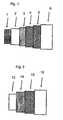
- FIG. 1is a schematic side view of a pipe with a carcass.
- FIG. 2is a schematic side view of a pipe without a carcass.
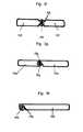
- FIGS. 3 a - 3 hare schematic cross sectional side views of a different folded metal strip with sensor arrangement(s), which can be a part of an armouring layer of the flexible pipe of the invention.
- FIG. 4is a schematic cross sectional side view of a first armouring layer comprising a folded metal strip with a sensor arrangement.
- FIG. 5is a schematic cross sectional side view of a second armouring layer comprising a folded metal strip with a sensor arrangement.
- FIG. 6is a schematic cross sectional side view of a third armouring layer comprising a folded metal strip with a sensor arrangement.
- the flexible pipe shown in FIG. 1comprises an internal sheath 2 , often also called an inner liner, e.g. of cross linked PE. Inside the inner liner 2 the pipe comprises an inner armouring layer 1 , called a carcass. On the outer side of the inner liner 2 , the flexible pipe comprises three outer armouring layers 3 , 4 , 5 .
- the inner armouring layer 3 closest to the inner liner 2is a pressure armouring layer 3 , made from profiles and/or strips wound at a steep angle to the centre axis of the pipe, e.g. close to 90 degrees.
- the pipecomprises a pair of cross wound tensile armouring layers 4 , 5 , made from wound profiles and/or strips, wherein one of the tensile armouring layers 4 has an angle above 55 degrees, typically between 60 and 75 degrees, and wherein the other one of the tensile armouring layers 5 has an angle below 55 degrees, typically between 30 and 45 degrees.
- the piperfurther comprises an outer polymer layer 6 protecting the armouring layer mechanically and/or against ingress of sea water.
- At least one of the armouring layers 2 , 3 , 4 , 5comprises at least one folded metal strip with a sensor arrangement as described above.
- FIG. 2shows another pipe design.
- This flexible pipecomprises an inner liner 12 and a pair of outer armouring layers, 14 , 15 , in the form of profiles and/or strips wound around the inner liner 12 .
- the two armouring layersare cross wound at an angle to the centre axis of the pipe of close to 55 degrees, typically one of the layers is wound at an angle slightly less than 55 degrees, e.g. between 52 and 55 degrees, and the other of them is wound at an angle slightly more than 55 degrees e.g. between 55 and 57.
- the pipefurther comprises an outer polymer layer 16 protecting the armouring layer mechanically and/or against ingress of sea water.
- At least one of the armouring layers 14 , 15comprises at least one folded metal strip with a sensor arrangement as described above.
- FIG. 3 ashows a cross sectional side view of a folded metal strip useful in a pressure vault of the pipe of the invention.
- the metal stripis folded to form two edge sections 31 a , 31 a ′, both protruding in the same direction, namely in the opposite direction than the folding direction.
- the metal stripis folded against itself in two folds along one of its edges 31 a ′.
- the folded metal stripis folded around a fiber 36 a of a sensor arrangement.
- the stripfurther comprises a non-folded mid-section 32 a , between the two edge sections 31 a , 31 a′.
- FIG. 3 bshows a cross sectional side view of another folded metal strip.
- the metal stripis folded to form two edge sections 31 b , 31 b ′, both protruding in the folding direction.
- the metal stripis folded against itself in two folds along one of its edges 31 b ′.
- the folded metal stripis folded around a fiber 36 b of a sensor arrangement.
- FIG. 3 cshows a cross sectional side view of another folded metal strip.
- the metal stripis folded to form two edge sections 31 c , 31 c ′, both protruding in the folding direction.
- the metal stripis folded against itself in three folds along one of its edges 31 c ′.
- the folded metal stripis folded around a fiber 36 c of a sensor arrangement in two folds.
- FIG. 3 dshows a cross sectional side view of another folded metal strip.
- the metal stripis folded to form two edge sections 31 d , both protruding in the folding direction.
- the metal stripis folded against itself along its edges in three folds for each of the edge sections 31 d whereby each protruding edge section 31 d has 4 or more strip material layers.
- the folded metal stripcomprises a box shaped fold 32 d into which a fiber 36 d of a sensor arrangement has been incorporated.
- FIG. 3 eshows a cross sectional side view of another folded metal strip, where the metal strip is folded to form two edge sections 31 e , 31 e ′, both protruding in the same direction.
- the metal stripis in each of its edge sections 31 e , 31 e ′ folded against a secondary element 35 e , 36 e , which elements are thereby integrated in the fold.
- One of the secondary elementsis a reinforcement element 53 e
- the other one of the secondary elementsis a fiber 36 e of a sensor arrangement.
- FIG. 3 fshows a cross sectional side view of another folded metal strip.
- This folded stripdoes not comprise any protruding edge section for interlocking purposes and is thus to be applied in a non-interlocked or partly-interlocked armouring layer.
- the metal stripis to form two box shaped sections 31 f . At the mid section between the two box shaped sections 31 f , the metal strip is folded to form two pairs of opposite protruding tops 32 f which tops 32 f holds and possibly fix a fiber 36 f of a sensor arrangement.
- FIG. 3 gshows a cross sectional side view of another folded metal strip.
- This folded stripdoes not comprise any protruding edge section for interlocking purposes and is thus to be applied in a non-interlocked or partly-interlocked armouring layer.
- the metal stripis to form a box shape 31 g .
- the metal stripis folded against itself to form a fold 32 g into which a fiber 36 g of a sensor arrangement has been incorporated.
- FIG. 3 hshows a cross sectional side view of another folded metal strip.
- This folded stripdoes not comprise any protruding edge section for interlocking purposes and is thus to be applied in a non-interlocked or partly-interlocked armouring layer.
- the metal stripis to form a box shape 31 h . Adjacent to one of the two edges of the box shaped folded strip, the metal strip is folded against itself to form a fold 32 h into which a fiber 36 h of a sensor arrangement has been incorporated.
- FIG. 4shows a first armouring layer of a flexible pipe of the invention comprising helically wound, interlocked folded strips 41 , 42 .
- the armouring layercomprises 2 or more (an even number—in the drawing at least 4) folded metal strips 41 , 42 , where half of the folded metal strips 41 are folded to have two box shaped folds 44 , and the other half of the folded metal strips 42 are only slightly folded along their edges in folds 43 to hold together consecutive windings of the first folded metal strip type 41 .
- a fiber 46 of a sensor arrangementhas been placed in one of the box shaped folds of one of the folded metal strips 41 .
- FIG. 5shows a second armouring layer of a flexible pipe of the invention comprising one or more helically wound, interlocked folded strips 51 (in the drawing at least 3).
- the helically wound strip(s) 51comprises a box shaped fold 54 along one of its edges and a slightly folded fold 53 along the other one of its edge. In its mid section the helically wound strip(s) 51 comprises a groove 57 which is engaged with the slightly folded fold 53 of another folded metal strip.
- a fiber 56 of a sensor arrangementhas been placed in the box shaped fold 54 of one of the folded metal strips 51 a fiber 56 of a sensor arrangement has been placed.
- FIG. 6shows a third armouring layer of a flexible pipe of the invention comprising interlocked folded strips 61 a , 61 b .
- the armouring layercomprises 2 or more (an even number) folded metal strips 61 a , 61 b . At least one of the folded metal strips 61 b is as the folded metal strip comprising an incorporated fiber 66 of a sensor arrangement.
- the folded metal strips 61 a , 61 bare turned opposite each other so that half of the folded metal strips 61 a , 61 b comprise protruding edge sections 62 protruding towards the hollow core of the pipe and the other half of the folded metal strips 61 a , 61 b comprise protruding edge sections 63 protruding away from the longitudinal axis of the pipe (here the hollow core).
- the folded metal strips 61 a , 61 bare wound helically onto the pipe so that the protruding edge sections 63 protruding away from the hollow core of the pipe are interlocked with protruding edge sections 62 protruding towards the hollow core of the pipe.
- the folded metal strip(s) 61 bcomprises an integrated fibre 66 , which is folded into one of its protruding edge sections.
- the pressure armouring layercomprises a hoop layer provided by a helically wound wire 65 (hoop wire), which in this embodiment is made from a formed strip such as a metal strip, which has been formed to have one or more box sections 65 a .
- the hoop wire 65increases the moment of inertia.
Landscapes
- Engineering & Computer Science (AREA)
- General Engineering & Computer Science (AREA)
- Physics & Mathematics (AREA)
- Mechanical Engineering (AREA)
- General Physics & Mathematics (AREA)
- Aviation & Aerospace Engineering (AREA)
- Chemical & Material Sciences (AREA)
- Analytical Chemistry (AREA)
- Electromagnetism (AREA)
- Rigid Pipes And Flexible Pipes (AREA)
- Length Measuring Devices By Optical Means (AREA)
Abstract
Description
Claims (36)
Applications Claiming Priority (7)
| Application Number | Priority Date | Filing Date | Title |
|---|---|---|---|
| DK200601706 | 2006-12-22 | ||
| DKPA200601706 | 2006-12-22 | ||
| PA200601706 | 2006-12-22 | ||
| DK200701205 | 2007-08-23 | ||
| PA200701205 | 2007-08-23 | ||
| DKPA200701205 | 2007-08-23 | ||
| PCT/DK2007/050189WO2008077410A1 (en) | 2006-12-22 | 2007-12-17 | A flexible pipe |
Publications (2)
| Publication Number | Publication Date |
|---|---|
| US20100089478A1 US20100089478A1 (en) | 2010-04-15 |
| US8474489B2true US8474489B2 (en) | 2013-07-02 |
Family
ID=39126622
Family Applications (1)
| Application Number | Title | Priority Date | Filing Date |
|---|---|---|---|
| US12/520,704Expired - Fee RelatedUS8474489B2 (en) | 2006-12-22 | 2007-12-17 | Flexible pipe |
Country Status (7)
| Country | Link |
|---|---|
| US (1) | US8474489B2 (en) |
| EP (1) | EP2092228B1 (en) |
| AT (1) | ATE498087T1 (en) |
| BR (1) | BRPI0720487B8 (en) |
| DE (1) | DE602007012466D1 (en) |
| NO (1) | NO337523B1 (en) |
| WO (1) | WO2008077410A1 (en) |
Cited By (5)
| Publication number | Priority date | Publication date | Assignee | Title |
|---|---|---|---|---|
| US10935166B2 (en) | 2018-12-20 | 2021-03-02 | The Boeing Company | Conduits for transporting fluids |
| US10935167B2 (en) | 2018-12-20 | 2021-03-02 | The Boeing Company | Conduits for transporting fluids |
| US10935170B2 (en) | 2018-12-20 | 2021-03-02 | The Boeing Company | Conduits for transporting fluids |
| US11035515B2 (en)* | 2018-12-20 | 2021-06-15 | The Boeing Company | Conduits for transporting fluids |
| US11835156B2 (en) | 2018-12-20 | 2023-12-05 | The Boeing Company | Conduits for transporting fluids and methods of fabricating the same |
Families Citing this family (47)
| Publication number | Priority date | Publication date | Assignee | Title |
|---|---|---|---|---|
| EP2450608A1 (en)* | 2007-11-26 | 2012-05-09 | Schlumberger Holdings Limited | Method of monitoring fluid flow within a flexible pipe |
| EP2265929A1 (en) | 2008-02-25 | 2010-12-29 | NKT Flexibles I/S | A pipe system, a fluid sensing system for a pipe system, and a method of determining a fluid component in an annulus cavity of a pipe |
| CN102057202A (en) | 2008-06-09 | 2011-05-11 | 最佳弹性产品公司 | Flexible pipe joint |
| GB0820671D0 (en) | 2008-11-12 | 2008-12-17 | Wellstream Int Ltd | Armour reinforcement |
| EP2494247B1 (en) | 2009-10-28 | 2016-12-07 | National Oilwell Varco Denmark I/S | A flexible pipe and a method of producing a flexible pipe |
| AU2010333431B2 (en) | 2009-12-15 | 2014-11-06 | National Oilwell Varco Denmark I/S | An unbonded, flexible pipe |
| CA2785256C (en) | 2009-12-28 | 2018-02-27 | National Oilwell Varco Denmark I/S | An unbonded, flexible pipe |
| EP2569566A4 (en) | 2010-05-12 | 2017-06-14 | National Oilwell Varco Denmark I/S | An unbonded flexible pipe |
| CA2805315A1 (en) | 2010-07-14 | 2012-01-19 | National Oilwell Varco Denmark I/S | An unbonded flexible pipe |
| GB201018538D0 (en)* | 2010-11-03 | 2010-12-15 | Wellstream Int Ltd | Parameter sensing |
| DK201001031A (en)* | 2010-11-12 | 2012-05-13 | Nat Oilwell Varco Denmark Is | A flexible pipe system |
| CA2823071A1 (en)* | 2011-01-20 | 2012-07-26 | National Oilwell Varco Denmark I/S | An unbonded flexible pipe |
| WO2012097823A1 (en) | 2011-01-20 | 2012-07-26 | National Ollwell Varco Denmark I/S | A flexible armored pipe |
| EP2707634A4 (en) | 2011-05-10 | 2015-02-25 | Nat Oilwell Varco Denmark Is | A flexible unbonded pipe |
| MX353187B (en) | 2011-10-04 | 2018-01-05 | Flexsteel Pipeline Tech Inc | Pipe end fitting with improved venting. |
| WO2013135243A1 (en) | 2012-03-13 | 2013-09-19 | National Oilwell Varco Denmark I/S | A reinforcement element for an unbonded flexible pipe |
| WO2013135244A1 (en) | 2012-03-13 | 2013-09-19 | National Oilwell Varco Denmark I/S | An unbonded flexible pipe with an optical fiber containing layer |
| WO2013152770A1 (en) | 2012-04-12 | 2013-10-17 | National Oilwell Varco Denmark I/S | A method of producing an unbonded flexible pipe and an unbonded flexible pipe |
| DK177627B1 (en) | 2012-09-03 | 2013-12-16 | Nat Oilwell Varco Denmark Is | An unbonded flexible pipe |
| EP2725186B1 (en) | 2012-10-25 | 2019-08-07 | GE Oil & Gas UK Limited | Sheath for flexible pipe bodies and method for producing the same |
| US9228428B2 (en)* | 2012-12-26 | 2016-01-05 | General Electric Company | System and method for monitoring tubular components of a subsea structure |
| GB2526247B (en) | 2014-03-12 | 2018-12-05 | Rtl Mat Ltd | Methods and apparatus relating to deployment of fibre optic assemblies by burial. |
| US9618435B2 (en)* | 2014-03-31 | 2017-04-11 | Dmar Engineering, Inc. | Umbilical bend-testing |
| EP3161366A1 (en)* | 2014-06-30 | 2017-05-03 | National Oilwell Varco Denmark I/S | An offshore pipe system and a method of heating unbonded flexible pipes in an offshore pipe system |
| GB201411874D0 (en) | 2014-07-03 | 2014-08-20 | Wellstream Int Ltd | Curvature sensor and sensing method |
| BR112017006628B1 (en) | 2014-09-30 | 2021-09-08 | Flexsteel Pipeline Technologies, Inc | PIPE CONNECTOR AND METHOD OF ASSEMBLY OF A PIPE CONNECTOR |
| EP3045794B1 (en)* | 2015-01-16 | 2019-05-15 | Nexans | Downhole cable with integrated non-metallic tube |
| CA2994867C (en) | 2015-08-10 | 2023-08-22 | Kristian Glejbol | A method of testing an unbonded flexible pipe |
| CA3004049C (en) | 2015-11-02 | 2021-06-01 | Flexsteel Pipeline Technologies, Inc. | Real time integrity monitoring of on-shore pipes |
| US10981765B2 (en) | 2016-06-28 | 2021-04-20 | Trinity Bay Equipment Holdings, LLC | Half-moon lifting device |
| US11208257B2 (en) | 2016-06-29 | 2021-12-28 | Trinity Bay Equipment Holdings, LLC | Pipe coil skid with side rails and method of use |
| BR112019007181A2 (en) | 2016-10-10 | 2019-07-02 | Trinity Bay Equipment Holdings Llc | coil hose installation trailer and method of use |
| WO2018071299A1 (en) | 2016-10-10 | 2018-04-19 | Trinity Bay Equipment Holdings, LLC | Expandable drum assembly for deploying coiled pipe and method of using same |
| US10526164B2 (en) | 2017-08-21 | 2020-01-07 | Trinity Bay Equipment Holdings, LLC | System and method for a flexible pipe containment sled |
| AU2018357973A1 (en) | 2017-11-01 | 2020-05-21 | Trinity Bay Equipment Holdings, LLC | System and method for handling reel of pipe |
| WO2019152779A2 (en) | 2018-02-01 | 2019-08-08 | Trinity Bay Equipment Holdings, LLC | Pipe coil skid with side rails and method of use |
| AR114640A1 (en) | 2018-02-22 | 2020-09-30 | Trinity Bay Equipment Holdings Llc | SYSTEM AND METHOD FOR DEPLOYING ROLLER TUBE COILS |
| WO2020077201A1 (en) | 2018-10-12 | 2020-04-16 | Trinity Bay Equipment Holdings, LLC | Installation trailer for coiled flexible pipe and method of utilizing same |
| AR118122A1 (en) | 2019-02-15 | 2021-09-22 | Trinity Bay Equipment Holdings Llc | FLEXIBLE TUBE HANDLING SYSTEM AND METHOD TO USE THE SAME |
| US10753512B1 (en) | 2019-03-28 | 2020-08-25 | Trinity Bay Equipment Holdings, LLC | System and method for securing fittings to flexible pipe |
| WO2021038098A1 (en) | 2019-08-30 | 2021-03-04 | National Oilwell Varco Denmark I/S | A pipe installation |
| US10926972B1 (en) | 2019-11-01 | 2021-02-23 | Trinity Bay Equipment Holdings, LLC | Mobile cradle frame for pipe reel |
| US11204114B2 (en) | 2019-11-22 | 2021-12-21 | Trinity Bay Equipment Holdings, LLC | Reusable pipe fitting systems and methods |
| BR112022010003A2 (en) | 2019-11-22 | 2022-08-16 | Trinity Bay Equipment Holdings Llc | SYSTEMS AND METHODS OF VESSEL TUBE FITTINGS |
| AU2020388644A1 (en) | 2019-11-22 | 2022-06-09 | Flexsteel Usa, Llc | Swaged pipe fitting systems and methods |
| US10822194B1 (en) | 2019-12-19 | 2020-11-03 | Trinity Bay Equipment Holdings, LLC | Expandable coil deployment system for drum assembly and method of using same |
| US10844976B1 (en) | 2020-02-17 | 2020-11-24 | Trinity Bay Equipment Holdings, LLC | Methods and apparatus for pulling flexible pipe |
Citations (38)
| Publication number | Priority date | Publication date | Assignee | Title |
|---|---|---|---|---|
| US714429A (en)* | 1902-09-02 | 1902-11-25 | Emil Witzenmann | Metallic spiral hose. |
| US3340900A (en) | 1964-10-13 | 1967-09-12 | Coleman Cable & Wire Company | Flexible galvanized metal hose |
| US3641658A (en) | 1969-04-23 | 1972-02-15 | Inst Francais Du Petrole | Process for coupling to a connecting element an elongated flexible member including lines for remote transmission of power or data |
| US4364418A (en) | 1978-04-17 | 1982-12-21 | Coflexip | Flexible tubular conduit |
| US4549581A (en) | 1984-03-20 | 1985-10-29 | The Furukawa Electric Co., Ltd. | Flexible pipe |
| US4697875A (en) | 1985-05-29 | 1987-10-06 | Societa Cavi Pirelli S.P.A. | Pressure resistant submarine optical fiber cable |
| EP0321262B1 (en) | 1987-12-17 | 1992-11-04 | Telephone Cables Limited | Optical fibre cable |
| US5343738A (en) | 1992-10-16 | 1994-09-06 | Furon Company | Double walled containment fuel transfer hose |
| US5669420A (en) | 1990-07-27 | 1997-09-23 | Coflexip | Casing and flexible tubular conduit comprising such a casing and process for producing it |
| US5730188A (en) | 1996-10-11 | 1998-03-24 | Wellstream, Inc. | Flexible conduit |
| US5813439A (en) | 1990-06-29 | 1998-09-29 | Herrero; Jose Mallen | Flexible tubular pipe comprising an interlocked armoring web and process for producing it |
| US6024135A (en) | 1994-12-01 | 2000-02-15 | Nobileau; Philippe | Flexible high pressure pipe |
| US6065501A (en) | 1989-06-30 | 2000-05-23 | Institute Francais Du Petrole | Flexible tube having at least one elongated reinforcing element with a T-shaped profile |
| WO2000036324A1 (en) | 1998-12-16 | 2000-06-22 | Nkt Flexibles I/S | Armoured flexible pipe and use of same |
| US6085799A (en) | 1996-01-22 | 2000-07-11 | Coflexip | Use of a buried flexible pipeline |
| US6110550A (en) | 1996-11-22 | 2000-08-29 | Institut Francais Du Petrole | Limited permeability sheath and application to pressure pipes |
| US6123114A (en) | 1998-02-18 | 2000-09-26 | Coflexip | Flexible pipe for riser in off-shore oil production |
| US6145546A (en) | 1999-06-03 | 2000-11-14 | Coflexip | Flexible flowline for conveying fluids |
| US6192941B1 (en) | 1994-12-05 | 2001-02-27 | Coflexip | Flexible tubular pipe comprising an interlocked armouring web |
| US6235793B1 (en) | 1997-01-21 | 2001-05-22 | Sanofi-Synthelabo | Use of agonists of adrenergic β-3 receptors for preparing wound-healing medicines |
| WO2001061232A1 (en) | 2000-02-16 | 2001-08-23 | Nkt Flexibles I/S | Flexible, armoured pipe and use of same |
| WO2001081809A1 (en) | 2000-04-25 | 2001-11-01 | Nkt Flexibles I/S | Armoured, flexible pipe and use of same |
| WO2002001104A1 (en) | 2000-06-30 | 2002-01-03 | Coflexip | Flexible conduit with flexible strip reinforcement |
| WO2002002309A1 (en) | 2000-06-30 | 2002-01-10 | Dwight Marcus | Controlled rigidity articles |
| US6354333B1 (en) | 1998-08-10 | 2002-03-12 | Coflexip | Resistant flexible pipe comprising sealing sleeve with limited creep |
| WO2002042674A1 (en) | 2000-11-24 | 2002-05-30 | Coflexip | Flexible tubular pipe |
| US6408891B1 (en) | 1998-02-18 | 2002-06-25 | Institut Francais Du Petrole | Flexible pipe for static use in a corrosive ambience |
| US6415825B1 (en) | 1998-10-12 | 2002-07-09 | Coflexip | Flexible conduit with high inertia hoop |
| US6454897B1 (en) | 1996-08-27 | 2002-09-24 | Coflexip | Method for manufacturing a flexible duct |
| WO2002088659A2 (en) | 2001-04-30 | 2002-11-07 | Nkt Flexibles I/S | A method of mounting a sensor arrangement in a tubular member, and use of the method |
| US6668867B2 (en) | 2000-04-21 | 2003-12-30 | Institut Francais Du Petrole & Coflexip | Flexible metal tube with closed section and flexible pipe comprising same |
| US6691743B2 (en) | 2000-05-10 | 2004-02-17 | Coflexip | Flexible pipe with wire or strip winding for maintaining armours |
| US20040055550A1 (en) | 2002-09-19 | 2004-03-25 | Borgwarner Inc. | Spool valve controlled VCT locking pin release mechanism |
| US20040261878A1 (en)* | 2001-10-24 | 2004-12-30 | Jung Patrice Joel Louis | Flexible tubular pipe for hydrocarbon transport wit carcass consisting of an elongated element stapled with a band iron |
| US20060151042A1 (en) | 2005-01-12 | 2006-07-13 | Stringfellow William D | Pipe liner |
| US7891384B2 (en)* | 2007-04-27 | 2011-02-22 | Technip France | Flexible tubular pipe for transporting gaseous hydrocarbons |
| US20110203695A1 (en)* | 2007-08-23 | 2011-08-25 | Nkt Flexibles I/S | flexible pipe |
| US8056585B2 (en)* | 2006-12-22 | 2011-11-15 | Nkt Flexibles I/S | Flexible pipe |
- 2007
- 2007-12-17EPEP07846449Apatent/EP2092228B1/ennot_activeNot-in-force
- 2007-12-17DEDE602007012466Tpatent/DE602007012466D1/enactiveActive
- 2007-12-17BRBRPI0720487Apatent/BRPI0720487B8/enactiveIP Right Grant
- 2007-12-17WOPCT/DK2007/050189patent/WO2008077410A1/enactiveApplication Filing
- 2007-12-17ATAT07846449Tpatent/ATE498087T1/ennot_activeIP Right Cessation
- 2007-12-17USUS12/520,704patent/US8474489B2/ennot_activeExpired - Fee Related
- 2009
- 2009-06-12NONO20092269Apatent/NO337523B1/enunknown
Patent Citations (43)
| Publication number | Priority date | Publication date | Assignee | Title |
|---|---|---|---|---|
| US714429A (en)* | 1902-09-02 | 1902-11-25 | Emil Witzenmann | Metallic spiral hose. |
| US3340900A (en) | 1964-10-13 | 1967-09-12 | Coleman Cable & Wire Company | Flexible galvanized metal hose |
| US3641658A (en) | 1969-04-23 | 1972-02-15 | Inst Francais Du Petrole | Process for coupling to a connecting element an elongated flexible member including lines for remote transmission of power or data |
| US4364418A (en) | 1978-04-17 | 1982-12-21 | Coflexip | Flexible tubular conduit |
| US4549581A (en) | 1984-03-20 | 1985-10-29 | The Furukawa Electric Co., Ltd. | Flexible pipe |
| US4697875A (en) | 1985-05-29 | 1987-10-06 | Societa Cavi Pirelli S.P.A. | Pressure resistant submarine optical fiber cable |
| EP0321262B1 (en) | 1987-12-17 | 1992-11-04 | Telephone Cables Limited | Optical fibre cable |
| US6065501A (en) | 1989-06-30 | 2000-05-23 | Institute Francais Du Petrole | Flexible tube having at least one elongated reinforcing element with a T-shaped profile |
| US6283161B1 (en) | 1989-06-30 | 2001-09-04 | Institut Francais Du Petrole | Flexible tube having at least one elongated reinforcing element with a t-shape |
| US5813439A (en) | 1990-06-29 | 1998-09-29 | Herrero; Jose Mallen | Flexible tubular pipe comprising an interlocked armoring web and process for producing it |
| US5669420A (en) | 1990-07-27 | 1997-09-23 | Coflexip | Casing and flexible tubular conduit comprising such a casing and process for producing it |
| US5343738A (en) | 1992-10-16 | 1994-09-06 | Furon Company | Double walled containment fuel transfer hose |
| US6024135A (en) | 1994-12-01 | 2000-02-15 | Nobileau; Philippe | Flexible high pressure pipe |
| US6192941B1 (en) | 1994-12-05 | 2001-02-27 | Coflexip | Flexible tubular pipe comprising an interlocked armouring web |
| US6085799A (en) | 1996-01-22 | 2000-07-11 | Coflexip | Use of a buried flexible pipeline |
| US6454897B1 (en) | 1996-08-27 | 2002-09-24 | Coflexip | Method for manufacturing a flexible duct |
| US5730188A (en) | 1996-10-11 | 1998-03-24 | Wellstream, Inc. | Flexible conduit |
| US6110550A (en) | 1996-11-22 | 2000-08-29 | Institut Francais Du Petrole | Limited permeability sheath and application to pressure pipes |
| US6235793B1 (en) | 1997-01-21 | 2001-05-22 | Sanofi-Synthelabo | Use of agonists of adrenergic β-3 receptors for preparing wound-healing medicines |
| US6123114A (en) | 1998-02-18 | 2000-09-26 | Coflexip | Flexible pipe for riser in off-shore oil production |
| US6408891B1 (en) | 1998-02-18 | 2002-06-25 | Institut Francais Du Petrole | Flexible pipe for static use in a corrosive ambience |
| US6354333B1 (en) | 1998-08-10 | 2002-03-12 | Coflexip | Resistant flexible pipe comprising sealing sleeve with limited creep |
| US6415825B1 (en) | 1998-10-12 | 2002-07-09 | Coflexip | Flexible conduit with high inertia hoop |
| WO2000036324A1 (en) | 1998-12-16 | 2000-06-22 | Nkt Flexibles I/S | Armoured flexible pipe and use of same |
| US6145546A (en) | 1999-06-03 | 2000-11-14 | Coflexip | Flexible flowline for conveying fluids |
| WO2001061232A1 (en) | 2000-02-16 | 2001-08-23 | Nkt Flexibles I/S | Flexible, armoured pipe and use of same |
| US6668867B2 (en) | 2000-04-21 | 2003-12-30 | Institut Francais Du Petrole & Coflexip | Flexible metal tube with closed section and flexible pipe comprising same |
| WO2001081809A1 (en) | 2000-04-25 | 2001-11-01 | Nkt Flexibles I/S | Armoured, flexible pipe and use of same |
| US6691743B2 (en) | 2000-05-10 | 2004-02-17 | Coflexip | Flexible pipe with wire or strip winding for maintaining armours |
| WO2002002309A1 (en) | 2000-06-30 | 2002-01-10 | Dwight Marcus | Controlled rigidity articles |
| WO2002001104A1 (en) | 2000-06-30 | 2002-01-03 | Coflexip | Flexible conduit with flexible strip reinforcement |
| WO2002042674A1 (en) | 2000-11-24 | 2002-05-30 | Coflexip | Flexible tubular pipe |
| US6840286B2 (en) | 2000-11-24 | 2005-01-11 | Coflexip | Flexible tubular pipe |
| US20040168521A1 (en) | 2001-04-30 | 2004-09-02 | Martin Andersen | Method of mounting a sensor arrangement in a tubular member, and use of the method |
| WO2002088659A2 (en) | 2001-04-30 | 2002-11-07 | Nkt Flexibles I/S | A method of mounting a sensor arrangement in a tubular member, and use of the method |
| US7024941B2 (en) | 2001-04-30 | 2006-04-11 | Nkt Flexibles I/S | Method of mounting a sensor arrangement in a tubular member, and use of the method |
| US20040261878A1 (en)* | 2001-10-24 | 2004-12-30 | Jung Patrice Joel Louis | Flexible tubular pipe for hydrocarbon transport wit carcass consisting of an elongated element stapled with a band iron |
| US6904939B2 (en) | 2001-10-24 | 2005-06-14 | Technip France | Flexible tubular pipe for hydrocarbon transport with carcass consisting of an elongated element stapled with a band iron |
| US20040055550A1 (en) | 2002-09-19 | 2004-03-25 | Borgwarner Inc. | Spool valve controlled VCT locking pin release mechanism |
| US20060151042A1 (en) | 2005-01-12 | 2006-07-13 | Stringfellow William D | Pipe liner |
| US8056585B2 (en)* | 2006-12-22 | 2011-11-15 | Nkt Flexibles I/S | Flexible pipe |
| US7891384B2 (en)* | 2007-04-27 | 2011-02-22 | Technip France | Flexible tubular pipe for transporting gaseous hydrocarbons |
| US20110203695A1 (en)* | 2007-08-23 | 2011-08-25 | Nkt Flexibles I/S | flexible pipe |
Non-Patent Citations (4)
| Title |
|---|
| Andersen, et al., "Development of an Optical Monitoring System for Flexible Risers", Offshore Technology Conference, 2001, Houston, TX. |
| Felix-Henry, "Thermal Performances of the Flexible Bundled Risers", Houston, TX, 2002, Technip-Coflexip, Offshore Technology Conference. |
| Felix-Henry, et al., "Flexible Pipes In-Service Monitoring", Vancouver, Canada, Jun. 20-25, 2004, 23rd International Conference on Offshore Mechanics and Arctic Engineering. |
| Felix-Henry, et al., "Flexible Risers Technologies in Deepwater and Ultra Deepwater", Houston, TX, 2003, Technip-Coflexip, Global Offshore. |
Cited By (9)
| Publication number | Priority date | Publication date | Assignee | Title |
|---|---|---|---|---|
| US10935166B2 (en) | 2018-12-20 | 2021-03-02 | The Boeing Company | Conduits for transporting fluids |
| US10935167B2 (en) | 2018-12-20 | 2021-03-02 | The Boeing Company | Conduits for transporting fluids |
| US10935170B2 (en) | 2018-12-20 | 2021-03-02 | The Boeing Company | Conduits for transporting fluids |
| US11035515B2 (en)* | 2018-12-20 | 2021-06-15 | The Boeing Company | Conduits for transporting fluids |
| US11371629B2 (en) | 2018-12-20 | 2022-06-28 | The Boeing Company | Conduits for transporting fluids and methods of fabricating the same |
| US11415244B2 (en) | 2018-12-20 | 2022-08-16 | The Boeing Company | Conduits for transporting fluids and methods of fabricating the same |
| US11428348B2 (en) | 2018-12-20 | 2022-08-30 | The Boeing Company | Methods of fabricating conduits for transporting fluids |
| US11512807B2 (en) | 2018-12-20 | 2022-11-29 | The Boeing Company | Conduits for transporting fluids and methods of fabricating the same |
| US11835156B2 (en) | 2018-12-20 | 2023-12-05 | The Boeing Company | Conduits for transporting fluids and methods of fabricating the same |
Also Published As
| Publication number | Publication date |
|---|---|
| EP2092228B1 (en) | 2011-02-09 |
| EP2092228A1 (en) | 2009-08-26 |
| BRPI0720487A8 (en) | 2016-01-19 |
| ATE498087T1 (en) | 2011-02-15 |
| BRPI0720487A2 (en) | 2014-02-04 |
| NO337523B1 (en) | 2016-05-02 |
| DE602007012466D1 (en) | 2011-03-24 |
| WO2008077410A1 (en) | 2008-07-03 |
| NO20092269L (en) | 2009-06-12 |
| BRPI0720487B8 (en) | 2020-12-01 |
| US20100089478A1 (en) | 2010-04-15 |
| BRPI0720487B1 (en) | 2019-08-06 |
Similar Documents
| Publication | Publication Date | Title |
|---|---|---|
| US8474489B2 (en) | Flexible pipe | |
| EP2185850B1 (en) | A flexible pipe | |
| US9188256B2 (en) | Flexible unbonded oil pipe system with an optical fiber sensor inside | |
| EP2635832B1 (en) | Flexible pipe and end fitting with integrated sensor | |
| US8985154B2 (en) | Heated pipe and methods of transporting viscous fluid | |
| CN103775740B (en) | Device and its manufacture method for flexible pipe body | |
| US7024941B2 (en) | Method of mounting a sensor arrangement in a tubular member, and use of the method | |
| US20160290539A1 (en) | An assembly comprising an unbonded flexible pipe and an end-fitting | |
| US6401760B2 (en) | Subsea flexible pipe of long length and modular structure | |
| US20130014849A1 (en) | Flexible unbonded pipe and an offshore system | |
| US20150136264A1 (en) | Flexible pipe body and method | |
| US20140338776A1 (en) | Flexible pipe body and method |
Legal Events
| Date | Code | Title | Description |
|---|---|---|---|
| AS | Assignment | Owner name:NKT FLEXIBLES I/S,DENMARK Free format text:ASSIGNMENT OF ASSIGNORS INTEREST;ASSIGNOR:GUDME, JONAS;REEL/FRAME:024070/0738 Effective date:20090626 Owner name:NKT FLEXIBLES I/S, DENMARK Free format text:ASSIGNMENT OF ASSIGNORS INTEREST;ASSIGNOR:GUDME, JONAS;REEL/FRAME:024070/0738 Effective date:20090626 | |
| AS | Assignment | Owner name:NATIONAL OILWELL VARCO DENMARK I/S, DENMARK Free format text:CHANGE OF NAME;ASSIGNOR:NKT FLEXIBLES I/S;REEL/FRAME:028375/0147 Effective date:20120426 | |
| STCF | Information on status: patent grant | Free format text:PATENTED CASE | |
| CC | Certificate of correction | ||
| FPAY | Fee payment | Year of fee payment:4 | |
| MAFP | Maintenance fee payment | Free format text:PAYMENT OF MAINTENANCE FEE, 8TH YEAR, LARGE ENTITY (ORIGINAL EVENT CODE: M1552); ENTITY STATUS OF PATENT OWNER: LARGE ENTITY Year of fee payment:8 | |
| FEPP | Fee payment procedure | Free format text:MAINTENANCE FEE REMINDER MAILED (ORIGINAL EVENT CODE: REM.); ENTITY STATUS OF PATENT OWNER: LARGE ENTITY | |
| LAPS | Lapse for failure to pay maintenance fees | Free format text:PATENT EXPIRED FOR FAILURE TO PAY MAINTENANCE FEES (ORIGINAL EVENT CODE: EXP.); ENTITY STATUS OF PATENT OWNER: LARGE ENTITY | |
| STCH | Information on status: patent discontinuation | Free format text:PATENT EXPIRED DUE TO NONPAYMENT OF MAINTENANCE FEES UNDER 37 CFR 1.362 | |
| FP | Lapsed due to failure to pay maintenance fee | Effective date:20250702 |