US8474460B2 - Implanted bronchial isolation devices and methods - Google Patents
Implanted bronchial isolation devices and methodsDownload PDFInfo
- Publication number
- US8474460B2 US8474460B2US12/885,199US88519910AUS8474460B2US 8474460 B2US8474460 B2US 8474460B2US 88519910 AUS88519910 AUS 88519910AUS 8474460 B2US8474460 B2US 8474460B2
- Authority
- US
- United States
- Prior art keywords
- valve
- air flow
- flow
- control device
- flow control
- Prior art date
- Legal status (The legal status is an assumption and is not a legal conclusion. Google has not performed a legal analysis and makes no representation as to the accuracy of the status listed.)
- Expired - Fee Related
Links
- 238000000034methodMethods0.000titleabstractdescription18
- 238000002955isolationMethods0.000titledescription8
- 230000004044responseEffects0.000claimsdescription23
- 230000001012protectorEffects0.000claimsdescription13
- 230000007423decreaseEffects0.000claimsdescription12
- 230000003434inspiratory effectEffects0.000claimsdescription11
- 239000000463materialSubstances0.000claimsdescription11
- 230000007704transitionEffects0.000claimsdescription8
- 230000003247decreasing effectEffects0.000claimsdescription3
- 230000006835compressionEffects0.000claimsdescription2
- 238000007906compressionMethods0.000claimsdescription2
- 239000012530fluidSubstances0.000abstractdescription119
- 210000004072lungAnatomy0.000abstractdescription114
- 230000029058respiratory gaseous exchangeEffects0.000abstractdescription12
- 230000001105regulatory effectEffects0.000abstractdescription4
- 238000011282treatmentMethods0.000abstractdescription4
- 238000005336crackingMethods0.000description25
- 210000000621bronchiAnatomy0.000description20
- 210000001519tissueAnatomy0.000description16
- 229920001296polysiloxanePolymers0.000description8
- 238000000576coating methodMethods0.000description7
- 238000013461designMethods0.000description7
- 230000002829reductive effectEffects0.000description7
- 210000003437tracheaAnatomy0.000description7
- 206010014561EmphysemaDiseases0.000description6
- 230000000694effectsEffects0.000description6
- 239000007789gasSubstances0.000description6
- 239000007788liquidSubstances0.000description6
- 239000012528membraneSubstances0.000description6
- 229910001000nickel titaniumInorganic materials0.000description5
- JOYRKODLDBILNP-UHFFFAOYSA-NEthyl urethaneChemical compoundCCOC(N)=OJOYRKODLDBILNP-UHFFFAOYSA-N0.000description4
- 230000008901benefitEffects0.000description4
- 230000006870functionEffects0.000description4
- HLXZNVUGXRDIFK-UHFFFAOYSA-Nnickel titaniumChemical compound[Ti].[Ti].[Ti].[Ti].[Ti].[Ti].[Ti].[Ti].[Ti].[Ti].[Ti].[Ni].[Ni].[Ni].[Ni].[Ni].[Ni].[Ni].[Ni].[Ni].[Ni].[Ni].[Ni].[Ni].[Ni]HLXZNVUGXRDIFK-UHFFFAOYSA-N0.000description4
- 230000036961partial effectEffects0.000description4
- 208000006545Chronic Obstructive Pulmonary DiseaseDiseases0.000description3
- 208000037265diseases, disorders, signs and symptomsDiseases0.000description3
- 238000003780insertionMethods0.000description3
- 230000037431insertionEffects0.000description3
- 238000007789sealingMethods0.000description3
- 239000004812Fluorinated ethylene propyleneSubstances0.000description2
- 208000019693Lung diseaseDiseases0.000description2
- 229920001774PerfluoroetherPolymers0.000description2
- VYPSYNLAJGMNEJ-UHFFFAOYSA-NSilicium dioxideChemical compoundO=[Si]=OVYPSYNLAJGMNEJ-UHFFFAOYSA-N0.000description2
- 210000001015abdomenAnatomy0.000description2
- 230000000903blocking effectEffects0.000description2
- 210000003123bronchioleAnatomy0.000description2
- UBAZGMLMVVQSCD-UHFFFAOYSA-Ncarbon dioxide;molecular oxygenChemical groupO=O.O=C=OUBAZGMLMVVQSCD-UHFFFAOYSA-N0.000description2
- 239000011248coating agentSubstances0.000description2
- 230000006378damageEffects0.000description2
- 238000007598dipping methodMethods0.000description2
- 201000010099diseaseDiseases0.000description2
- 239000006185dispersionSubstances0.000description2
- 230000000977initiatory effectEffects0.000description2
- 230000004048modificationEffects0.000description2
- 238000012986modificationMethods0.000description2
- 230000037361pathwayEffects0.000description2
- 229920009441perflouroethylene propylenePolymers0.000description2
- 210000003281pleural cavityAnatomy0.000description2
- 229920001343polytetrafluoroethylenePolymers0.000description2
- 239000004810polytetrafluoroethyleneSubstances0.000description2
- 238000004381surface treatmentMethods0.000description2
- KIUKXJAPPMFGSW-DNGZLQJQSA-N(2S,3S,4S,5R,6R)-6-[(2S,3R,4R,5S,6R)-3-Acetamido-2-[(2S,3S,4R,5R,6R)-6-[(2R,3R,4R,5S,6R)-3-acetamido-2,5-dihydroxy-6-(hydroxymethyl)oxan-4-yl]oxy-2-carboxy-4,5-dihydroxyoxan-3-yl]oxy-5-hydroxy-6-(hydroxymethyl)oxan-4-yl]oxy-3,4,5-trihydroxyoxane-2-carboxylic acidChemical compoundCC(=O)N[C@H]1[C@H](O)O[C@H](CO)[C@@H](O)[C@@H]1O[C@H]1[C@H](O)[C@@H](O)[C@H](O[C@H]2[C@@H]([C@@H](O[C@H]3[C@@H]([C@@H](O)[C@H](O)[C@H](O3)C(O)=O)O)[C@H](O)[C@@H](CO)O2)NC(C)=O)[C@@H](C(O)=O)O1KIUKXJAPPMFGSW-DNGZLQJQSA-N0.000description1
- 206010006458Bronchitis chronicDiseases0.000description1
- 241000169624Casearia sylvestrisSpecies0.000description1
- 241000405070PercophidaeSpecies0.000description1
- HZEWFHLRYVTOIW-UHFFFAOYSA-N[Ti].[Ni]Chemical compound[Ti].[Ni]HZEWFHLRYVTOIW-UHFFFAOYSA-N0.000description1
- 230000002411adverseEffects0.000description1
- 210000004712air sacAnatomy0.000description1
- XAGFODPZIPBFFR-UHFFFAOYSA-NaluminiumChemical compound[Al]XAGFODPZIPBFFR-UHFFFAOYSA-N0.000description1
- 229910052782aluminiumInorganic materials0.000description1
- PNEYBMLMFCGWSK-UHFFFAOYSA-Naluminium oxideInorganic materials[O-2].[O-2].[O-2].[Al+3].[Al+3]PNEYBMLMFCGWSK-UHFFFAOYSA-N0.000description1
- 210000003484anatomyAnatomy0.000description1
- 208000006673asthmaDiseases0.000description1
- QVGXLLKOCUKJST-UHFFFAOYSA-Natomic oxygenChemical group[O]QVGXLLKOCUKJST-UHFFFAOYSA-N0.000description1
- 230000009286beneficial effectEffects0.000description1
- 239000000560biocompatible materialSubstances0.000description1
- 229920000249biocompatible polymerPolymers0.000description1
- 201000009267bronchiectasisDiseases0.000description1
- 206010006451bronchitisDiseases0.000description1
- 208000007451chronic bronchitisDiseases0.000description1
- 230000001684chronic effectEffects0.000description1
- 235000019504cigarettesNutrition0.000description1
- 229910052681coesiteInorganic materials0.000description1
- 238000010276constructionMethods0.000description1
- 230000001276controlling effectEffects0.000description1
- 229910052906cristobaliteInorganic materials0.000description1
- 238000005520cutting processMethods0.000description1
- 238000002716delivery methodMethods0.000description1
- 238000011161developmentMethods0.000description1
- 239000013013elastic materialSubstances0.000description1
- 210000004177elastic tissueAnatomy0.000description1
- 229920001971elastomerPolymers0.000description1
- 239000000806elastomerSubstances0.000description1
- 239000013536elastomeric materialSubstances0.000description1
- 239000003344environmental pollutantSubstances0.000description1
- 229920002674hyaluronanPolymers0.000description1
- 229960003160hyaluronic acidDrugs0.000description1
- 239000007943implantSubstances0.000description1
- 238000002513implantationMethods0.000description1
- 230000006872improvementEffects0.000description1
- 238000001746injection mouldingMethods0.000description1
- 150000002500ionsChemical class0.000description1
- 230000000670limiting effectEffects0.000description1
- 238000004519manufacturing processMethods0.000description1
- 230000005012migrationEffects0.000description1
- 238000013508migrationMethods0.000description1
- 230000001473noxious effectEffects0.000description1
- 229910052760oxygenInorganic materials0.000description1
- 239000001301oxygenSubstances0.000description1
- RVTZCBVAJQQJTK-UHFFFAOYSA-Noxygen(2-);zirconium(4+)Chemical compound[O-2].[O-2].[Zr+4]RVTZCBVAJQQJTK-UHFFFAOYSA-N0.000description1
- 210000003105phrenic nerveAnatomy0.000description1
- 230000004962physiological conditionEffects0.000description1
- -1polytetrafluoroethylenePolymers0.000description1
- 230000002685pulmonary effectEffects0.000description1
- 230000000306recurrent effectEffects0.000description1
- 230000002441reversible effectEffects0.000description1
- 238000000926separation methodMethods0.000description1
- 239000000377silicon dioxideSubstances0.000description1
- 229910052709silverInorganic materials0.000description1
- 239000004332silverSubstances0.000description1
- 230000000391smoking effectEffects0.000description1
- 229910001220stainless steelInorganic materials0.000description1
- 239000010935stainless steelSubstances0.000description1
- 230000000638stimulationEffects0.000description1
- 229910052682stishoviteInorganic materials0.000description1
- 208000024891symptomDiseases0.000description1
- 230000001360synchronised effectEffects0.000description1
- 230000008685targetingEffects0.000description1
- 229910052905tridymiteInorganic materials0.000description1
Images


Classifications
- A—HUMAN NECESSITIES
- A61—MEDICAL OR VETERINARY SCIENCE; HYGIENE
- A61B—DIAGNOSIS; SURGERY; IDENTIFICATION
- A61B17/00—Surgical instruments, devices or methods
- A61B17/12—Surgical instruments, devices or methods for ligaturing or otherwise compressing tubular parts of the body, e.g. blood vessels or umbilical cord
- A61B17/12022—Occluding by internal devices, e.g. balloons or releasable wires
- A61B17/12099—Occluding by internal devices, e.g. balloons or releasable wires characterised by the location of the occluder
- A61B17/12104—Occluding by internal devices, e.g. balloons or releasable wires characterised by the location of the occluder in an air passage
- A—HUMAN NECESSITIES
- A61—MEDICAL OR VETERINARY SCIENCE; HYGIENE
- A61B—DIAGNOSIS; SURGERY; IDENTIFICATION
- A61B17/00—Surgical instruments, devices or methods
- A61B17/12—Surgical instruments, devices or methods for ligaturing or otherwise compressing tubular parts of the body, e.g. blood vessels or umbilical cord
- A61B17/12022—Occluding by internal devices, e.g. balloons or releasable wires
- A61B17/12131—Occluding by internal devices, e.g. balloons or releasable wires characterised by the type of occluding device
- A61B17/12168—Occluding by internal devices, e.g. balloons or releasable wires characterised by the type of occluding device having a mesh structure
- A61B17/12172—Occluding by internal devices, e.g. balloons or releasable wires characterised by the type of occluding device having a mesh structure having a pre-set deployed three-dimensional shape
- A—HUMAN NECESSITIES
- A61—MEDICAL OR VETERINARY SCIENCE; HYGIENE
- A61F—FILTERS IMPLANTABLE INTO BLOOD VESSELS; PROSTHESES; DEVICES PROVIDING PATENCY TO, OR PREVENTING COLLAPSING OF, TUBULAR STRUCTURES OF THE BODY, e.g. STENTS; ORTHOPAEDIC, NURSING OR CONTRACEPTIVE DEVICES; FOMENTATION; TREATMENT OR PROTECTION OF EYES OR EARS; BANDAGES, DRESSINGS OR ABSORBENT PADS; FIRST-AID KITS
- A61F2/00—Filters implantable into blood vessels; Prostheses, i.e. artificial substitutes or replacements for parts of the body; Appliances for connecting them with the body; Devices providing patency to, or preventing collapsing of, tubular structures of the body, e.g. stents
- A61F2/02—Prostheses implantable into the body
- A61F2/24—Heart valves ; Vascular valves, e.g. venous valves; Heart implants, e.g. passive devices for improving the function of the native valve or the heart muscle; Transmyocardial revascularisation [TMR] devices; Valves implantable in the body
- A61F2/2412—Heart valves ; Vascular valves, e.g. venous valves; Heart implants, e.g. passive devices for improving the function of the native valve or the heart muscle; Transmyocardial revascularisation [TMR] devices; Valves implantable in the body with soft flexible valve members, e.g. tissue valves shaped like natural valves
- A—HUMAN NECESSITIES
- A61—MEDICAL OR VETERINARY SCIENCE; HYGIENE
- A61F—FILTERS IMPLANTABLE INTO BLOOD VESSELS; PROSTHESES; DEVICES PROVIDING PATENCY TO, OR PREVENTING COLLAPSING OF, TUBULAR STRUCTURES OF THE BODY, e.g. STENTS; ORTHOPAEDIC, NURSING OR CONTRACEPTIVE DEVICES; FOMENTATION; TREATMENT OR PROTECTION OF EYES OR EARS; BANDAGES, DRESSINGS OR ABSORBENT PADS; FIRST-AID KITS
- A61F2/00—Filters implantable into blood vessels; Prostheses, i.e. artificial substitutes or replacements for parts of the body; Appliances for connecting them with the body; Devices providing patency to, or preventing collapsing of, tubular structures of the body, e.g. stents
- A61F2/02—Prostheses implantable into the body
- A61F2/04—Hollow or tubular parts of organs, e.g. bladders, tracheae, bronchi or bile ducts
- A61F2002/043—Bronchi
Definitions
- COPDchronic obstructive pulmonary disease
- emphysema and other pulmonary diseasesreduce the ability of one or both lungs to fully expel air during the exhalation phase of the breathing cycle.
- One of the effects of such diseasesis that the diseased lung tissue is less elastic than healthy lung tissue, which is one factor that prevents full exhalation of air.
- the diseased portion of the lungdoes not fully recoil due to the diseased (e.g., emphysematic) lung tissue being less elastic than healthy tissue.
- the diseased lung tissueexerts a relatively low driving force, which results in the diseased lung expelling less air volume than a healthy lung.
- the reduced air volumeexerts less force on the airway, which allows the airway to close before all air has been expelled, another factor that prevents full exhalation.
- the problemis further compounded by the diseased, less elastic tissue that surrounds the very narrow airways that lead to the alveoli, which are the air sacs where oxygen-carbon dioxide exchange occurs.
- the diseased tissuehas less tone than healthy tissue and is typically unable to maintain the narrow airways open until the end of the exhalation cycle. This traps air in the lungs and exacerbates the already-inefficient breathing cycle. The trapped air causes the tissue to become hyper-expanded and no longer able to effect efficient oxygen-carbon dioxide exchange.
- hyper-expanded, diseased lung tissueoccupies more of the pleural space than healthy lung tissue. In most cases, a portion of the lung is diseased while the remaining part is relatively healthy and, therefore, still able to efficiently carry out oxygen exchange.
- the hyper-expanded lung tissuereduces the amount of space available to accommodate the healthy, functioning lung tissue. As a result, the hyper-expanded lung tissue causes inefficient breathing due to its own reduced functionality and because it adversely affects the functionality of adjacent healthy tissue.
- Some recent treatmentsinclude the use of devices that isolate a diseased region of the lung in order to reduce the volume of the diseased region, such as by collapsing the diseased lung region.
- one or more flow control devicesare implanted in airways feeding a diseased region of the lung to regulate fluid flow to the diseased lung region in order to fluidly isolate the region of the lung.
- These implanted flow control devicescan be, for example, one-way valves that allow flow in the exhalation direction only, occluders or plugs that prevent flow in either direction, or two-way valves that control flow in both directions.
- implanted flow control devicescan be, for example, one-way valves that allow flow in the exhalation direction only, occluders or plugs that prevent flow in either direction, or two-way valves that control flow in both directions.
- such devicesare still in the development stages.
- a flow control device suitable for implanting in a bronchial passagewaycomprises a valve defining a variable-sized mouth through which fluid can flow through the valve to regulate fluid flow through the bronchial passageway.
- the mouthincreases in size in response to fluid flow in a first direction and decreases in size in response to fluid flow in a second direction.
- the mouthis open when the valve is in a default state.
- a fluid flow control devicesuitable for implanting in a bronchial passageway, comprising: a frame configured to retain the flow control device within the bronchial passageway; a seal coupled to the frame, the seal configured to seal against internal walls of the bronchial passageway; and a valve coupled to the frame, the valve having lips that define a variable-sized mouth through which fluid can flow through the valve, wherein the lips move away from one another to increase the size of the mouth in response to fluid flow in a first direction and move toward one another to decrease the size of the mouth in response to fluid flow in a second direction, and wherein the lips are at least partially spaced apart to define an open mouth when the valve is exposed to no fluid flow.
- a fluid flow control devicesuitable for implanting in a bronchial passageway, comprising a frame configured to retain the flow control device within the bronchial passageway; a seal coupled to the frame, the seal configured to seal against internal walls of the bronchial passageway; and a valve that resists fluid flow in an inspiratory direction through the bronchial passageway, wherein the valve's resistance to fluid flow varies as a function of a pressure differential across the valve.
- a fluid flow control devicesuitable for implanting in a bronchial passageway, comprising a frame configured to retain the flow control device within the bronchial passageway; a seal coupled to the frame, the seal configured to seal against internal walls of the bronchial passageway; and a valve that resists fluid flow in an inspiratory direction through the bronchial passageway, wherein the valve transitions to a state of increased resistance to fluid flow in response to an increase in a rate of fluid flow through the bronchial passageway.
- a flow control devicesuitable for implanting in a bronchial passageway, comprising a valve element that transitions between an open configuration that permits fluid flow in an inspiratory direction and a closed configuration that blocks fluid flow in the inspiratory direction, wherein a default state of the valve element is the open configuration.
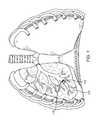
- FIG. 1shows an anterior view of a pair of human lungs and a bronchial tree with a flow control device implanted in a bronchial passageway to bronchially isolate a region of the lung.
- FIG. 2illustrates an anterior view of a pair of human lungs and a bronchial tree.
- FIG. 3Aillustrates a lateral view of the right lung.
- FIG. 3Billustrates a lateral view of the left lung.
- FIG. 4illustrates an anterior view of the trachea and a portion of the bronchial tree.
- FIG. 5Ashows a perspective view of an exemplary flow control device that can be implanted in a body passageway.
- FIG. 5Bshows a perspective, cross-sectional view of the flow control device of FIG. 5A .
- FIG. 6Ashows a side view of the flow control device of FIG. 5A .
- FIG. 6Bshows a cross-sectional, side view of the flow control device of FIG. 5A .
- FIG. 7shows another embodiment of a flow control device.
- FIG. 8shows a bi-leaflet valve with open mouth for use in a flow control device.
- FIG. 9shows a trilobular valve for use in a flow control device.
- FIGS. 10A and 10Bshows two views of a bronchial isolation device with an open-mouth flap valve.
- FIG. 11shows an open, oval-mouth valve for use in a flow control device.
- FIG. 12shows a valve in a fully open state.
- FIG. 13shows a valve in a partially closed state.
- FIG. 14shows a valve in a fully closed state.
- FIG. 15shows a sharp-corner, open-mouth valve for us in a flow control device.
- FIG. 16A-16Cshow various views of a high-flow valve with pleated sides.
- FIG. 17shows a mandrel and a dipped” parallel-lipped valve manufactured using the mandrel for use in a flow control device.
- FIG. 18shows a bonded parallel-lipped Heimlich valve.
- FIG. 19shows another embodiment of a valve for use in a flow control device.
- FIG. 20is an enlarged elevation view of the lungs of a patient along with a further embodiment of the system of the invention.
- FIG. 21is an enlarged elevation view, in section, of a flow control element forming part of the system shown in FIG. 20 , wherein the flow control element allows fluid flow in a first direction but blocks fluid flow in a second direction.
- FIG. 22is an enlarged elevation view, in section, of an alternative flow control element that allows fluid flow in a first direction but blocks fluid flow in a second direction.
- an identified region of the lungreferred to herein as the “targeted lung region” is targeted for treatment.
- the targeted lung regionis then bronchially isolated to regulate airflow into and/or out of the targeted lung region through one or more bronchial passageways that feed air to the targeted lung region.
- the bronchial isolation of the targeted lung regionis accomplished by implanting a flow control device 110 (sometimes referred to as a bronchial isolation device) into a bronchial passageway 115 that feeds air to a targeted lung region 120 .
- the flow control device 110regulates fluid flow through the bronchial passageway 115 in which the flow control device 110 is implanted.
- the flow control device 110can regulate airflow through the bronchial passageway 115 using a valve that permits fluid flow in a first direction (e.g., the exhalation direction) while limiting or preventing fluid flow in a second direction (e.g., the inhalation direction).
- the valveincludes coaptation regions, such as lips, that are moveable toward and away from one another so as to define a variable sized opening through which fluid can flow.
- coaptation regionssuch as lips
- the coaptation regionsWhen exposed to fluid flow in the first direction (e.g., the exhalation direction), the coaptation regions are urged away from one another to increase the size of the opening therebetween and permit an increasing amount of fluid flow through the valve.
- the coaptation regionsare urged toward one another to decrease the size of and/or completely close the opening to decrease and/or completely prevent fluid flow through the valve. Flow through the valve is completely prevented when the coaptation regions are completely shut such that there is no opening for fluid to flow through the valve.
- the valveIn conventional flow control devices, the valve is closed in a default state such that there is no gap or opening between the coaptation regions of the valve.
- the coaptation regionsseparate from one another to form an opening for fluid flow in the first direction when the valve cracking pressure is exceeded.
- the coaptation regionssuch as the valve lips
- the sticking force between the coaptation regionscan be stronger when the valve is implanted in a lung, as mucous can coat the valve lips and form surface tension that must be overcome to separate the lips and open the valve.
- the flow control device 110can include a valve that is “normally-open” in a default state such that at least a portion of the coaptation regions are separated from one another to define an opening therebetween. Because the coaptation regions are separated from one another in a default state, such a valve has a reduced cracking pressure as there is a little or no tendency for the coaptation regions to stick together. In addition, the gap between the coaptation regions reduces or eliminates the effect of surface tension caused by mucous on the valve.
- a normally-open valvealso permits increased fluid flow in the first direction (relative to a valve that is closed in the default state), as the default open state of the valve reduces bulk resistance to flow in the first direction.
- lung regionrefers to a defined division or portion of a lung.
- lung regionsare described herein with reference to human lungs, wherein some exemplary lung regions include lung lobes and lung segments.
- lung regioncan refer, for example, to a lung lobe or a lung segment.
- Such nomenclatureconform to nomenclature for portions of the lungs that are known to those skilled in the art.
- lung regiondoes not necessarily refer to a lung lobe or a lung segment, but can refer to some other defined division or portion of a human or nonhuman lung.
- FIG. 2shows an anterior view of a pair of human lungs 210 , 215 and a bronchial tree 220 that provides a fluid pathway into and out of the lungs 210 , 215 from a trachea 225 , as will be known to those skilled in the art.
- the term “fluid”can refer to a gas, a liquid, or a combination of gas(es) and liquid(s).
- FIG. 2shows only a portion of the bronchial tree 220 , which is described in more detail below with reference to FIG. 5 .
- FIG. 2shows a path 202 that travels through the trachea 225 and through a bronchial passageway into a location in the right lung 210 .
- proximal directionrefers to the direction along such a path 202 that points toward the patient's mouth or nose and away from the patient's lungs.
- the proximal directionis generally the same as the expiration direction when the patient breathes.
- the arrow 204 in FIG. 2points in the proximal or expiratory direction.
- the term “distal direction”refers to the direction along such a path 202 that points toward the patient's lung and away from the mouth or nose.
- the distal directionis generally the same as the inhalation or inspiratory direction when the patient breathes.
- the arrow 206 in FIG. 2points in the distal or inhalation direction.
- the lungsinclude a right lung 210 and a left lung 215 .
- the right lung 210includes lung regions comprised of three lobes, including a right upper lobe 230 , a right middle lobe 235 , and a right lower lobe 240 .
- the lobes 230 , 235 , 240are separated by two interlobar fissures, including a right oblique fissure 226 and a right transverse fissure 228 .
- the right oblique fissure 226separates the right lower lobe 240 from the right upper lobe 230 and from the right middle lobe 235 .
- the right transverse fissure 228separates the right upper lobe 230 from the right middle lobe 235 .
- the left lung 215includes lung regions comprised of two lobes, including the left upper lobe 250 and the left lower lobe 255 .
- An interlobar fissure comprised of a left oblique fissure 245 of the left lung 215separates the left upper lobe 250 from the left lower lobe 255 .
- the lobes 230 , 235 , 240 , 250 , 255are directly supplied air via respective lobar bronchi, as described in detail below.
- FIG. 3Ais a lateral view of the right lung 210 .
- the right lung 210is subdivided into lung regions comprised of a plurality of bronchopulmonary segments. Each bronchopulmonary segment is directly supplied air by a corresponding segmental tertiary bronchus, as described below.
- the bronchopulmonary segments of the right lung 210include a right apical segment 310 , a right posterior segment 320 , and a right anterior segment 330 , all of which are disposed in the right upper lobe 230 .
- the right lung bronchopulmonary segmentsfurther include a right lateral segment 340 and a right medial segment 350 , which are disposed in the right middle lobe 235 .
- the right lower lobe 240includes bronchopulmonary segments comprised of a right superior segment 360 , a right medial basal segment (which cannot be seen from the lateral view and is not shown in FIG. 3A ), a right anterior basal segment 380 , a right lateral basal segment 390 , and a right posterior basal segment 395 .
- FIG. 3Bshows a lateral view of the left lung 215 , which is subdivided into lung regions comprised of a plurality of bronchopulmonary segments.
- the bronchopulmonary segmentsinclude a left apical segment 410 , a left posterior segment 420 , a left anterior segment 430 , a left superior segment 440 , and a left inferior segment 450 , which are disposed in the left lung upper lobe 250 .
- the lower 15 lobe 225 of the left lung 215includes bronchopulmonary segments comprised of a left superior segment 460 , a left medial basal segment (which cannot be seen from the lateral view and is not shown in FIG. 3B ), a left anterior basal segment 480 , a left lateral basal segment 490 , and a left posterior basal segment 495 .
- FIG. 4shows an anterior view of the trachea 225 and a portion of the bronchial tree 220 , which includes a network of bronchial passageways, as described below.
- the trachea 225divides at a lower end into two bronchial passageways comprised of primary bronchi, including a right primary bronchus 510 that provides direct air flow to the right lung 210 , and a left primary bronchus 515 that provides direct air flow to the left lung 215 .
- Each primary bronchus 510 , 515divides into a next generation of bronchial passageways comprised of a plurality of lobar bronchi.
- the right primary bronchus 510divides into a right upper lobar bronchus 517 , a right middle lobar bronchus 520 , and a right lower lobar bronchus 522 .
- the left primary bronchus 515divides into a left upper lobar bronchus 525 and a left lower lobar bronchus 530 .
- Each lobar bronchus, 517 , 520 , 522 , 525 , 530directly feeds fluid to a respective lung lobe, as indicated by the respective names of the lobar bronchi.
- the lobar bronchieach divide into yet another generation of bronchial passageways comprised of segmental bronchi, which provide air flow to the bronchopulmonary segments discussed above.
- a bronchial passagewaydefines an internal lumen through which fluid can flow to and from a lung or lung region.
- the diameter of the internal lumen for a specific bronchial passagewaycan vary based on the bronchial passageway's location in the bronchial tree (such as whether the bronchial passageway is a lobar bronchus or a segmental bronchus) and can also vary from patient to patient.
- the internal diameter of a bronchial passagewayis generally in the range of 3 millimeters (mm) to 10 mm, although the internal diameter of a bronchial passageway can be outside of this range.
- a bronchial passagewaycan have an internal diameter of well below 1 mm at locations deep within the lung.
- implantation of one-way flow control devices or valve bronchial isolation deviceshas been employed, as described in several prior U.S. patent applications, including “Methods and Devices for use in Performing Pulmonary Procedures”, Ser. No. 09/797,910, filed Mar. 2, 2001 and “Bronchial Flow Control Devices and Methods of Use”, Ser. No. 10/270,792, filed Oct. 10, 2002, which are incorporated herein by reference.
- at least some of the bronchial isolation devicesinclude one-way valves that remain closed and sealed in a default state, such as when there is no pressure differential across the valve.
- FIGS. 5A-6Bshow an exemplary embodiment of a flow control device 110 that generally includes a valve, a frame or anchor, and a seal member for sealing against a wall of a bronchial passageway.
- the flow control device 110 shown in FIGS. 5A-6Bis exemplary and that the frame, seal member, and valve can vary in structure.
- the valvedoes not have to be configured with a central opening for fluid flow. Rather, the valve can be configured to interact with the walls of the bronchial passageway to permit or block fluid flow in that the valves contact or withdraw from the bronchial walls to block or permit fluid flow.
- the flow control device 110has a general outer shape and contour that permits the flow control device 110 to fit entirely or at least partially within a body passageway, such as within a bronchial passageway.
- the valveis configured to regulate fluid flow through a bronchial passageway in which the device 110 is implanted.
- the valveopens and vents fluid (such as gas or liquid, including mucous) when the pressure across the valve due to flow in a first direction, such as the exhalation direction, exceeds the rated cracking pressure of the valve.
- a first directionsuch as the exhalation direction
- the valveopens in response to fluid flow in the first direction.
- the valvemoves towards a closed configuration in response to fluid flow in a second, opposite direction such as the inhalation direction.
- the flow control device 110extends generally along a central axis 605 (shown in FIGS. 5B and 6B ).
- the flow control device 110includes a main body that defines an interior lumen 610 through which fluid can flow along a flow path.
- the dimensions of the flow control device 110can vary based upon the bronchial passageway in which the flow control device 110 is configured to be implanted.
- the valvedoes not have to be precisely sized for the bronchial passageway it is to be placed within.
- the diameter D (shown in FIG. 6A ) of the flow control device 110 in the uncompressed stateis larger than the inner diameter of the bronchial passageway in which the flow control device 110 will be placed. This will permit the flow control device 110 to be compressed prior to insertion in the bronchial passageway and then expand upon insertion in the bronchial passageway, which will provide for a secure fit between the flow control device 110 and the bronchial passageway.
- the flow of fluid through the interior lumen 610is controlled by a valve 612 that is disposed at a location along the interior lumen such that fluid must flow through the valve 612 in order to flow through the interior lumen 610 .
- the valve 612could be positioned at various locations along the interior lumen 610 .
- the valve 612can be made of a biocompatible material, such as a biocompatible polymer, such as silicone. As discussed in more detail below, the configuration of the valve 612 can vary based on a variety of factors, such as the desired cracking pressure of the valve 612 .
- the valve 612can be configured to permit fluid to flow in only one-direction through the interior lumen 610 , to permit regulated flow in two-directions through the interior lumen 610 , or to prevent fluid flow in either direction.
- the flow control device 110includes a seal member 615 that provides a seal with the internal walls of a body passageway when the flow control device is implanted into the body passageway.
- the seal member 615is manufactured of a deformable material, such as silicone or a deformable elastomer.
- the flow control device 110also includes an anchor member or frame 625 that functions to anchor the flow control device 110 within a body passageway.
- the seal member 615can includes a series of radially-extending, circular flanges 620 that surround the outer circumference of the flow control device 110 .
- the configuration of the flangescan vary.
- the radial length of each flange 620can vary. It should be appreciated that the radial length could be equal for all of the flanges 620 or that the radial length of each flange could vary in some other manner.
- the flanges 620can be oriented at a variety of angles relative to the longitudinal axis 605 of the flow control device.
- the anchor member 625functions to anchor the flow control device 110 in place when the flow control device is implanted within a body passageway, such as within a bronchial passageway.
- the anchor member 625has a structure that can contract and expand in size (in a radial direction and/or in a longitudinal direction) so that the anchor member can expand to grip the interior walls of a body passageway in which the flow control device is positioned.
- the anchor member 625comprises an annular frame that surrounds the flow control device 110 .
- the frame 625can be formed from a super-elastic material, such as Nickel Titanium (also known as Nitinol), such as by cutting the frame out of a tube of Nitinol or by forming the frame out of Nitinol wire.
- a super-elastic materialsuch as Nickel Titanium (also known as Nitinol)
- NitinolNickel Titanium
- the super-elastic properties of Nitinolcan result in the frame exerting a radial force against the interior walls of a bronchial passageway sufficient to anchor the flow control device 110 in place.
- the configurations, including the sizes and shapes, of the frame 625 and the seal member 615can vary from those shown in the figures.
- the seal 615 and/or the frame 625can contract or expand in size, particularly in a radial direction.
- the default stateis an expanded size, such that the flow control device 110 will have a maximum diameter (which is defined by either the seal 615 or the frame 625 ) when the flow control device 110 is in the default state.
- the flow control device 110can be radially contracted in size during insertion into a bronchial passageway, so that once the flow control device 110 is inserted into the passageway, it expands within the passageway.
- valve protector member 637is a tubular member or annular wall that is contained inside the seal member 615 .
- the valve protectorcan comprise a coil of wire or a ring of wire that provides some level of structural support to the flow control device.
- the valve protector 637can be concentrically located within the seal member 615 .
- the valve 612can be completely molded within the seal member 615 such that the material of the seal member 615 completely surrounds the valve protector.
- the valve protectorhas sufficient rigidity to maintain the shape of the valve member against compression.
- the valve protector member 637has two or more windows 639 comprising holes that extend through the valve protector member, as shown in FIG. 6B .
- the windows 639can provide a location where a removal device, such as graspers or forceps, can be inserted in order to facilitate removal of the flow control device 110 from a bronchial passageway.
- FIG. 7shows a perspective view of another embodiment of a flow control device 110 that includes a frame 625 , a valve 612 mounted in the frame 625 , and a membrane 627 .
- the frame 625 and the membrane 627can collectively or individually seal with an internal wall of a bronchial passageway.
- the valve in a flow control deviceopens and vents fluid (such as gas or liquid, including mucous) when the pressure differential across the valve due to flow in the first direction, such as the exhalation direction, exceeds the rated cracking pressure of the valve.
- fluidsuch as gas or liquid, including mucous
- Applicanthas determined that the lower the cracking pressure and the higher the level of fluid flow in the first direction through the valve once it has cracked, the better the performance of the flow control device for certain circumstances. This is because a greater amount of fluid (gas or liquid) will be expelled from the target lung region through the valve during exhalation.
- the valvemay be configured to be open in a default state.
- the valveis “open” in that there is an opening for fluid to flow through.
- the openingis typically defined by a gap between the coaptation regions of the valve, such as a gap between the lips of a valve.
- a valve that is open in the default stateis referred to herein as a “normally-open” valve.
- In the default statethere is no pressure differential across the valve.
- a pressure differentialcan be achieved as a result of the valve being exposed to the flow of fluid.
- the coaptation regions of the valveare at least partially separated from one another to define a gap or opening therebetween.
- a valve of a flow control deviceincludes regions (referred to herein as coaptation regions) that contact one another to block flow through the valve, and separate from one another to allow flow through the valve.
- the coaptation regionscan contact one another along their entire length or area such that there is no gap between therebetween and the valve is completely closed.
- the coaptation regionscan also partially contact one another such that there is at least a partial opening therebetween. For a normally-open valve, the coaptation regions at least form a partial opening in the default state.
- the coaptation regionscan comprise, for example, opposed lips that contact one another in a duckbill valve.
- the valve 612comprises a duckbill valve that includes two opposed, inclined walls or flaps 631 (shown in FIGS. 5B and 6B ) that are oriented at an angle with respect to one another.
- the flaps 631can open and close with respect to one another so as to form an opening between coaptation regions comprised of lips 801 ( FIG. 6B ).
- the relative positions of the lips 801determines the size of the opening in the valve 612 . When the lips are in full contact with one another, there is no opening between the coaptation regions.
- the valve shown in FIGS. 5A-6Bhas such a configuration.
- the valve coaptation regionsare in full contact with one another in a default state, such as when there is no pressure differential across the valve. That is, the coaptation regions are in contact with one another such that there is no opening for fluid to flow through.
- the default stateis the state of the valve when exposed to no fluid flow and, therefore, no pressure differential across the valve.
- valvesthat are normally-open in a default state.
- the coaptation regionssuch as the lips of a duckbill valve
- the coaptation regionsare not in contact with one another or only partially contact one another so as to form an opening therebetween.
- such a valvehas a reduced cracking pressure with respect to a valve that is closed in the default state.
- the gap between the coaptation regionsreduces or eliminates any “sticking force” between the coaptation region, which sticking force resists cracking of the valve.
- the gap between the lipsreduces or eliminates surface tension that can be caused by mucous lining the coaptation regions. Such surface tension must be overcome in order to crack the valve.
- valveis at least partially open in the default state, bulk resilience of the valve is decreased so that the valve has less resistance to flow in the first direction than for a normally-closed valve at the same pressure. This can result in a higher flow through the valve in the first direction once the valve is cracked.
- FIG. 8shows an exemplary embodiment of a normally-open duckbill valve 805 that can be used in the flow control device 110 .
- the valve 805is manufactured with a measurable gap 807 between the coaptation regions.
- the coaptation regionscomprise two or more lips 810 a , 810 b that are joined at opposing ends and that define the valve opening.
- the lips 810 a , 810 bdo not contact one another along their length in a default state, but rather are separated to form the opening 807 .
- the first directione.g., the expiration direction, represented by arrow 812 in FIG. 8
- the lips 810 a and 810 bare urged away from one another to increase the size of the opening 807 .
- the lips 810 a , 810 bdo not contact one another in the default, there is no sticking force to overcome in order for the flow in the first direction to urge the lips apart from each other.
- the valve 805is exposed to flow in the second direction (e.g., the inspiratory direction, represented by arrow 814 in FIG. 8 ) the lips 810 a and 810 b are urged toward one another. If exposed to a sufficient level of flow in the second direction, the lips 810 a and 810 b can fully contact one another to completely close the opening 807 .
- FIG. 9shows another embodiment of a normally-open valve 905 having a trilobular configuration.
- the trilobular valve 905has a single, contoured wall that is shaped so as to form three lobes defined by outside corners 920 and inside corners 925 .
- the wallhas coaptation regions comprised of lips 915 that define an opening 910 in a default state. When exposed to fluid flow in the first direction 812 , the lips 915 separate to increase the size of the opening 910 . When exposed to fluid flow in the second direction 814 , the lips 915 move toward one another to decrease the size of the opening 910 .
- the radius of the outside corners 920 and the inside corners 925 formed by the contours of the wall of the trilobular valve 905can be gently curved as shown in FIG. 9 , or can have a very sharp radius or can be sharp corners with no radius at all. Alternately, the valve may have four or more lobes.
- FIGS. 10A and 10Bshows another embodiment of a flow control device 1010 that is similar in configuration to the device 110 described above.
- the flow control device 1010has a valve 1020 having a flap valve configuration.
- the valve 1010has a flap 1025 and a seat 1030 .
- the flap 1025opens and closes relative to the seat 1030 .
- the flap 1025moves away from the seat 1030 in response to fluid flow in the first direction 812 to increase the size of the opening 1040 through which fluid flows.
- the flap 1025moves toward the seat 1030 in response to fluid flow in the second direction 814 to decrease the size of the opening 1040 .
- the flap 1025can completely contact the seat 1030 to close the opening 1040 when exposed to a sufficient level of fluid flow in the second direction.
- a flow control device equipped with a normally-open valvewhen implanted into a bronchial passageway of a patient, opens wider more quickly in response to fluid flow in the expiratory direction and with a lower driving pressure with respect to a valve that is closed in its default state. This leads to greater exhalation of fluid during exhalation.
- the size of the opening or amount of separation between the coaptation regions of the valve in the default statecan vary.
- the valveis completely open or near completely open in the default state.
- the valveallows its maximum, level of flow therethrough or a flow level that is substantially near its maximum.
- a valveis “partially open”, it allows less than the maximum level.
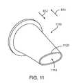
- FIG. 11shows an exemplary valve 1110 that has an opening 1115 defined by lips 1120 .
- the opening 1115is oval-shaped in a default state.
- fluid flow in the first direction 812urges the lips 1120 away from one another to increase the size of the opening 1115 .
- Fluid flow in the second direction 814urges the lips 1120 toward each other to decrease and possibly close the opening 1115 .
- the valveis partially open in the default state and the valve opens more fully as the valve is exposed to fluid flow in a first direction, such as in the exhalation direction.
- the size of the openingdecreases when exposed to fluid flow in the second direction, such as the inhalation direction. That is, the valve transitions from a partially open state toward a completely open state as the valve is exposed to an increasing level of fluid flow in the first direction.
- the valvemight completely open when exposed to fluid flow in the first direction. How close the valve gets to being completely open depends on the level of flow in the first direction.
- the valvetransitions from the partially open state toward the closed state. The valve might fully close depending on the level of flow in the second direction, although does not necessarily fully close.
- the opening in the valveincreased as flow moves through the valve in the first direction, such as the exhalation direction.
- the valve shown in FIG. 8shows an example of a valve that opens more fully when exposed to fluid flow in the first direction.
- the cracking pressureshould be sufficiently low such that the valve will easily crack open and vent fluid during all conditions of flow in a particular direction, such as exhalation.
- valveis configured to open in response to exhalation flow, this results in the valve cracking open more quickly once exhalation has begun, and once open, the maximum possible flow of fluid will occur through the valve. This will result in the maximum emptying of fluid from the targeting lung unit during exhalation, and the maximum benefit to the patient.
- a valveWhen a valve is designed to be biased closed such that the valve is completely closed in a default state, the geometrical and material properties inherent in such a valve can add some degree of cracking pressure and some limitation to the level of flow through the valve. Applicant has determined that a valve has beneficial properties when the valve is not biased completely closed such that the coaptation regions do not contact one another when there is zero pressure differential across the valve. Such a valve opens with less resistance to flow and therefore allows much greater flow through it during exhalation (with respect to a valve that is closed in the default state). It should be appreciated that a normally-open valve can be biased toward the closed position but that the bias is not so strong as to completely close the valve. Thus, a normally-open valve can be biased toward a partially-closed configuration.
- the coaptation regions of a valvecontact one another in the default state, the coaptation regions, typically formed of an elastomeric material, tend to stick together.
- the resulting “sticking force”must be overcome in order to crack the valve open, thus increasing the cracking pressure.
- This “sticking force”may be reduced by coating the coaptation regions with a material that reduces sticking between the coaptation regions.
- Some possible coatingsinclude polytetrafluoroethylene (PTFE), perfluoroalkoxy (PFA), fluorinated ethylenepropylene (FEP) or other flouropolymer, parlylene, hydrophilic coatings such as hyaluronic acid, various ion implanted or otherwise applied coatings such as silver, alumina (Al 2 O 3 ) or sialon (SiO 2 /N/Al 2 O 3 ), etc. It should be appreciated that this is not a complete list of possible coatings or surface treatments, and other coatings or surface treatments that reduce the “sticking force” of the coaptation regions are possible.
- a normally-closed valveis typically designed with some elastic resilience or spring bias so that some force from fluid flow through the valve must be applied to the coaptation regions in order to force them apart and allow fluid flow through the valve. This has the effect of raising the cracking pressure of the valve and of reducing the flow at a given driving pressure.
- valveIn designing a normally-open valve, there are a few design factors that can be considered. In general, if it is desired that the valve close at very low flows in the second direction (e.g., the inhalation direction), the valve will likely have some restriction to opening in response to fluid flow in the second direction (e.g., exhalation direction). If it is desired that the valve have the lowest possible restriction to exhaled flow, the valve will likely require a higher flow in the inhalation direction to close the valve. In addition, when closed, the valve may still allow a slight flow leak in the inhalation direction, which can be a disadvantage. Such a disadvantage may be more than compensated for by an increase in the flow through the valve in the exhalation direction. If the valve is of a duckbill or Heimlich type where there are two coaptation regions such as lips that come in contact with each other to seal the valve, the valve may be designed to have either of these characteristics or to be somewhere in between.
- the valvewill have a very high flow rate in a first direction (e.g. the exhalation direction) yet will require a threshold amount of flow in the second direction (e.g., the inhalation direction) to close the valve.
- a first directione.g. the exhalation direction
- a threshold amount of flow in the second directione.g., the inhalation direction
- the valvecan also be configured to allow flow at a low rate to move through the valve without ever completely closing the valve at all. That is, the valve is completely or partially open when exposed to no fluid flow and gradually closes when exposed to flow in the second direction such that the valve increasingly closes as the rate of fluid flow in the second direction increases. When closed to a maximum closing capacity, the valve may have some leak paths that allow a low level of flow in the second direction, such as the inhalation direction.
- a valve 1210is shown in FIG. 12 through FIG. 15 .
- the valve 1210is shown completely open in FIG. 12 , which means that the valve is open to its maximum capacity. Alternately, the valve 1210 can be partially open in FIG. 12 . In FIG.
- the valve 1210is partially closed in response to flow in the second direction (reverse flow).
- the lips of the valveare in partial contact with each other in FIG. 13 . That is, the lips contact one another along a central region, but are separated from each other along opposed edges to form small openings at the opposed edges. It should be appreciated that the lips can contact each other at various locations along their length or area when in partial contact.
- the valveis completely closed by a higher level of flow in the second direction.
- the valveprovides increased resistance to fluid flow in the second direction as the level of fluid flow in the second direction increases.
- the valves described hereincan be configured to provide increased resistance to fluid flow as the level or rate of fluid flow in the second direction increases.
- the fluid flowoccurs as a result of a pressure differential across the valve.
- the pressure differentialmay be such that fluid flows in the second direction (such as the inspiratory direction).
- the pressure on the proximal side of the valveis greater than the pressure on the distal side of the valve.
- the valve's resistance to fluid flow in the inspiratory directionalso increases.
- the resistance to fluid flowcan gradually increase as the pressure differential and the rate of fluid flow increases.
- the valve's resistance to fluid flowcan also suddenly increases when the pressure differential or rate of fluid flow increases beyond a threshold.
- the valvecan resist fluid flow in an inspiratory direction through the bronchial passageway, wherein the valve transitions to a state of increased resistance to fluid flow in response to an increase in a rate of fluid flow through the bronchial passageway.
- the valvemay not necessarily reach the completely closed state shown in FIG. 14 .
- the maximum closed state of the valvecan be some variation of the valve as shown in FIG. 13 , with the size(s) of the opening(s) between the lips being larger or smaller in the maximum closed state.
- the valve in the second directionthere may be leak paths through the valve; such as in the corners of the valve mouth.
- the leak pathscan allow some fluid flow through the valve when exposed to flow in the second direction, such as during inhalation.
- the valvegradually closes when exposed to increasing flow in the second direction and opens when exposed to flow in the first direction. It should be appreciated that the first direction need not correspond to the expiration direction and that the second direction need not correspond to the inhalation direction.
- the valve of the flow control devicecan be configured so that it does not close suddenly, and may behave more like a variable resistance valve in that the resistance to flow in the second direction increases as the level of flow in the second direction through the valve increases, as shown in FIG. 12 through FIG. 14 .
- the valvemay be configured to close quickly so that once a flow threshold required to close the valve is exceeded, the valve closes quickly.
- the valve in FIG. 8is such a valve. If the valve is configured such that the coaptation regions are very close together when there is no flow through the valve (as shown in FIG. 8 ), the valve will have a lower flow in the first direction (e.g. exhalation direction) yet will close at a very low flow in the second direction (e.g. inhalation direction).
- valvesWhen the valve is closed to a maximum, the valve may be designed to completely block flow in the second direction (such as under inhalation pressures and flows), or may allow a relatively low level of flow in the second direction. It should be appreciated that valves may be designed between these extremes and may be of other designs such as flap valves, trilobular valves, etc.
- FIG. 15shows another exemplary valve 1610 .
- the valve 1610has coaptation regions comprised of lips 1612 that meet at opposed corners 1613 .
- the shape of the opening 1615is defined by the lips 1612 .
- the corners 1613 of the opening 1615form a very sharp angle, such as, for example, in the range of 1 to 10 degrees. It should be appreciated that the foregoing corner angles are exemplary and can vary. For example, the corner angle could be greater than 10 degrees.
- the two lips 1612meet or contact one another tightly without leaving any openings therebetween. In this way, leaks in the second direction (e.g., the inhalation direction) may be prevented or reduced, while at the same time retaining the low cracking’ pressure and high exhalation flow that come with a normally-open valve.
- valve 1610 of FIG. 15Another feature of the valve 1610 of FIG. 15 is the length (when measured along the central axis of the device in the fluid flow direction) of the valve lips 1612 , which are longer than those found in the more standard duckbill valve shown mounted in the bronchial isolation device of FIG. 5A-7 .
- the lips 1612are parallel to one another for an extended length, such as, for example, approximately 0.010 to 0.100 inches. It should be appreciated that the extended lip length can vary based on the relative size of the valve. This extended length of the coaptation regions where the lips are parallel lowers the pressure required to close the valve in the inhalation direction while maintaining the low cracking pressure of a normally-open bi-leaflet valve.
- the wall thickness of the valve walls for a duckbill valvemay be reduced relative to conventional valve. If the valve is constructed of silicone, either molded or dipped, an optimal wall thickness may be as low as 0.002′′ or 0.003′′. As mentioned previously, the valve may also be constructed of other elastomeric materials, such as urethane.
- the valveWhen the valve is constructed with thin walls, the valve may be less resistant to inversion, or turning inside-out, when pressure is applied across the valve in the flow direction that closes the valve (such as in the inhalation direction). When a valve inverts, the valve ceases to perform as a one-way valve, so it is desirable to avoid inversion during expected inhalation flows and pressures. If a valve such as that shown in FIG. 15 is mounted into a flow control device, such as the device shown in FIG. 5A-7 , the pressure at which inversion occurs may be greatly increased by bonding or otherwise attaching or “tethering” at least a portion 1620 of the valve, such as one side of the valve, to the inside of the valve protector member 637 ( FIG. 5A ) of the flow control device 110 .
- valve protector member 637 on one side of the valvegreatly raises the pressure required for the valve to invert, yet does not greatly increase cracking pressure or reduce flow through the valve.
- the valvemay be bonded to the valve protector in two or more locations.
- the wall thickness of the valve componentmay be tapered so that it is thicker at the base of the valve to reduce inversion potential, yet is thinner at the mouth of the valve in order to keep the crack pressure low and the flow high.
- FIG. 19An alternate valve embodiment of a valve 2010 is shown in FIG. 19 .
- the valve 2010has coaptation regions comprised of lips 2012 that meet at opposed corners 2013 in the same fashion as the valve shown in FIG. 15 , however this embodiment differs in that the lips 2012 continue to be split apart around both sides of the valve 2014 .
- This modificationallows the valve to open farther and allows a larger level of flow in the exhalation direction.
- There is an opening 2015 in the default state that is defined by the lips 2012however the valve may also be constructed without the opening 2015 in order to produce a valve which is not normally open in the default state.
- FIGS. 17A-17CAn alternate valve embodiment of a valve 1710 is shown in FIGS. 17A-17C .
- the valve 1710has pleated sides 1715 and a mouth 1720 that is open in a default state.
- the pleated sides 1715allow the valve 1710 to close and seal with minimal flow in the second direction (e.g. inhalation direction), yet when the flow is reversed and fluid starts to move through the valve in the first direction (e.g. exhalation direction), the pleats allow the valve to open very widely, thus allowing a very high flow rate.
- a normally-closed valvehas the advantage of minimizing retrograde flow through the valve at the expense of increased cracking pressure and resistance to flow in the exhalation direction.
- a normally-open valvehas the advantage of reducing cracking pressure and reducing resistance to flow in a first direction (e.g., the exhalation direction), but at the expense of increases in flow prior to valve closing in the second direction or leaking 20 after closure. Additionally, the physiological conditions at which valves must operate vary greatly between patients and even within the same patient under different conditions.
- An “active” valveis actuated by some power source to open completely with little or no flow or pressure differential at the initiation of exhalation and then rapidly close and seal immediately at the initiation of inhalation.
- An active valveovercomes some drawbacks of passive valves.
- Ser. No. 10/298,387which is incorporated here by reference and assigned to the same assignee as the instant application, the inventors described various devices and methods of implantable pumps that would actively move fluid through the bronchial anatomy regardless of pressure and flow conditions across the valve. Under some 10 physiologic conditions or because of greater simplicity in design, the use of an active valve may be more desirable than a passive valve.
- the active valveis synchronized with the patient's breathing.
- One methodis to convert the mechanical movement of the abdomen into an electrical pulse by having the patient wear an elastic belt with integrated pressure transducers about the abdomen.
- the pressure belttransmits this electrical signal, either wired, through radio waves or other methods, to a controller for the actuator of the implanted valve(s).
- Alternately sensing stimulation of the phrenic nerve during normal respirationcan be used as the pacing signal to actuate the valve to open during exhalation and close during inhalation.
- the active valvecould be a flap valve, a bi-leaflet valve, a tri-leaflet valve, or any other valve that one skilled in the art could create.
- a bi-leaflet or duckbill valveis configured with a relatively long coaptation region, such as lips that are parallel to each other as shown in FIGS. 15 and 19 .
- This type of valvemay be designed as a normally-open valve where the two parallel lips are spaced apart by a predetermined distance, or the valve may have the two lips that are in contact with each other along the length of the lips.
- a mandrel 1810is formed out of aluminum, stainless steel or other suitable material in the shape of the desired inside surfaces of the valve.
- the mandrel 1810is then dipped in a silicone, urethane or other suitable dispersion to coat the outer surface of the mandrel 1810 .
- the coatingis then cured in an appropriate fashion to form the valve, and the valve is stripped off of the mandrel 1810 as shown in FIG. 17 .
- the tip 1705 of the valveis trimmed to expose the opening in the valve (as dipping will cover the tip of the mandrel thus closing off the opening at the valve mouth), thus leaving a valve with an open center lumen with parallel sealing surfaces.
- other methods of forming the normally-open, parallel-lipped valvessuch as injection molding, etc may be used.
- a parallel-lipped valveis normally-closed in that the lips are in contact with each other when there is no pressure differential across the valve.
- the valveis formed by heat bonding two sheets of urethane to each other using a bonding die that is formed in the desired shape of the valve.
- a bonding diethat is formed in the desired shape of the valve.
- other materials and methodscould be used to form a normally-closed parallel lipped valve.
- a flap valveis a style of valve that may be designed to have a low cracking pressure and a high flow once cracked.
- conventional flap valvesdo not remains closed and sealed with no flow through the valve.
- One way to improve the sealing of a flap valveis to add an elastic tether, formed for example from silicone, to the flap to assist in holding the valve down against the valve seat.
- the flap valve 1010 shown in FIGS. 10A and 10Bcan have a tether mounted to the flap 1025 to urge the flap 1025 toward the seat 1030 .
- the tetherWhen a pressure differential is applied to the valve in the exhalation direction, the tether is stretched and the valve opens. When there is no pressure across the valve, the tether holds the flap against the valve seat, thus preventing leakage through the valve.
- the tetheris not elastic and does not stretch when the valve opens. Instead, the edges of the flap component deflect away from the valve seat when the valve opens.
- OccluderThere are times when an implanted occlusion flow control device, instead of a one-way or two-way valve device, is clinically indicated for the isolation of lung tissue.
- the device shown in FIG. 7can be modified to act as an occluder.
- the valve 612 in FIG. 7is replaced with an occluding member that blocks flow through the flow control device.
- the device 110 in FIG. 7includes an elastically expandable frame 625 that is covered with an elastomeric membrane 627 .
- the devicehas an expanded frame laser-cut from nitinol tubing that has been expanded and heat treated to set it in the shape shown.
- the frame 625is dipped in a silicone dispersion so that all outer surfaces are covered in a thin silicone membrane.
- the deviceWhen the device is compressed into a delivery catheter, it may be delivered through the trachea, using any of a number of well know delivery methods, to the target bronchial lumen, and released from the catheter. Once released, the device expands and grip the walls of the bronchial lumen, and due to the silicone membrane, blocks fluid (gas and liquid) flow through the lumen in both the inhalation and exhalation directions.
- the frame 625can have points or prongs on the distal end to prevent migration of the device in the distal or inhalation direction.
- the framemay be made of other materials and take other shapes, may be deformable or heat expandable rather than spring resilient, and the membrane may be formed from other materials (such as urethane) and may be manufactured using methods other than dipping.
- This particular deviceis compact enough to fit into a delivery catheter that can fit through the working channel of a bronchoscope that has an internal diameter of 2.2 mm, however it may be delivered using other methods.
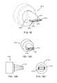
- FIG. 20is an enlarged view of the patient's lungs L similar to that shown in FIG. 1 .
- the flow control element 2122is left in the bronchiole 28 .
- the flow control element 2122shown in more detail in FIG. 21 , is in the form of a valve with a valve member 2132 supported by a ring 2134 .
- FIG. 20also illustrates a second flow control element 2122 A placed in a bronchiole 2128 A that feeds a lower lobe LL of the lung.
- the flow control element 2122 Aincludes a valve member 2132 A and a support ring 2134 A and reduces or prevents fluid from being inhaled into the hyper-expanded tissue of the lower lobe LL. It will be understood that any number of flow control elements may be used in a given procedure.
- valve member 2132is a duckbill-type valve and has two flaps defining an opening 2136 .
- the valve member 2132is shown in a flow-preventing orientation in FIG. 21 with the opening 2136 closed.
- the valve member 2132is configured to allow fluid flow in a first direction (along arrow A) while controlling fluid flow in a second direction (along arrow B).
- fluid flow in the direction of arrow Bis controlled by being completely blocked by valve member 2132 .
- the first and second directions in which fluid flow is allowed and controlled, respectively,are preferably opposite or substantially opposite each other, for example, as shown in the Figures. It will be appreciated, though, that the invention may be practiced with the first and second directions different but not opposite each other.
- valve member 2132 of the flow control element 2122controls fluid flow by completely blocking such flow in the second direction.
- valve member 2132effectively functions as a one-way valve.
- Alternative embodiments of the inventionutilize flow control elements that controls fluid flow in the second direction without completely blocking such flow.
- FIG. 22shows an exemplary flow control element 2138 constructed according to an alternative embodiment of the invention that limits, but does not block, fluid flow in at least one direction.
- the flow control element 2138comprises a valve member 2140 supported by a ring 2142 .
- the valve member 2140is preferably a duckbill-type valve having a similar construction to that of the valve member 2132 , except that the flaps 2144 are formed, secured, oriented or otherwise configured to maintain a flow opening 2146 when in their flow-controlling (as opposed to flow-allowing) orientation.
- the opening 2146is sized and configured to achieve desired flow characteristics through the flow control element 2138 .
- FIG. 22shows only one way to achieve limited fluid flow in a given direction.
- the specific manner in which flow control is obtainedmay vary according to the invention, e.g., by varying the number, size, shape or position of the flow openings on the flow control element.
Landscapes
- Health & Medical Sciences (AREA)
- Surgery (AREA)
- Life Sciences & Earth Sciences (AREA)
- Heart & Thoracic Surgery (AREA)
- Nuclear Medicine, Radiotherapy & Molecular Imaging (AREA)
- Vascular Medicine (AREA)
- Engineering & Computer Science (AREA)
- Biomedical Technology (AREA)
- Reproductive Health (AREA)
- Medical Informatics (AREA)
- Molecular Biology (AREA)
- Animal Behavior & Ethology (AREA)
- General Health & Medical Sciences (AREA)
- Public Health (AREA)
- Veterinary Medicine (AREA)
- Prostheses (AREA)
Abstract
Description
Claims (13)
Priority Applications (1)
| Application Number | Priority Date | Filing Date | Title |
|---|---|---|---|
| US12/885,199US8474460B2 (en) | 2000-03-04 | 2010-09-17 | Implanted bronchial isolation devices and methods |
Applications Claiming Priority (7)
| Application Number | Priority Date | Filing Date | Title |
|---|---|---|---|
| US09/519,735US6679264B1 (en) | 2000-03-04 | 2000-03-04 | Methods and devices for use in performing pulmonary procedures |
| US10/630,473US7165548B2 (en) | 2000-03-04 | 2003-07-29 | Methods and devices for use in performing pulmonary procedures |
| US55147604P | 2004-03-08 | 2004-03-08 | |
| US11/075,633US20060020347A1 (en) | 2004-03-08 | 2005-03-08 | Implanted bronchial isolation devices and methods |
| US11/395,396US7662181B2 (en) | 2000-03-04 | 2006-03-30 | Methods and devices for use in performing pulmonary procedures |
| US12/264,849US8357139B2 (en) | 2000-03-04 | 2008-11-04 | Methods and devices for use in performing pulmonary procedures |
| US12/885,199US8474460B2 (en) | 2000-03-04 | 2010-09-17 | Implanted bronchial isolation devices and methods |
Related Parent Applications (1)
| Application Number | Title | Priority Date | Filing Date |
|---|---|---|---|
| US11/075,633Continuation-In-PartUS20060020347A1 (en) | 2000-03-04 | 2005-03-08 | Implanted bronchial isolation devices and methods |
Publications (2)
| Publication Number | Publication Date |
|---|---|
| US20110226238A1 US20110226238A1 (en) | 2011-09-22 |
| US8474460B2true US8474460B2 (en) | 2013-07-02 |
Family
ID=44646214
Family Applications (1)
| Application Number | Title | Priority Date | Filing Date |
|---|---|---|---|
| US12/885,199Expired - Fee RelatedUS8474460B2 (en) | 2000-03-04 | 2010-09-17 | Implanted bronchial isolation devices and methods |
Country Status (1)
| Country | Link |
|---|---|
| US (1) | US8474460B2 (en) |
Cited By (45)
| Publication number | Priority date | Publication date | Assignee | Title |
|---|---|---|---|---|
| US9375327B2 (en) | 2007-12-12 | 2016-06-28 | Intact Vascular, Inc. | Endovascular implant |
| US20160256277A1 (en)* | 2015-03-02 | 2016-09-08 | Georgia Tech Research Corporation | Implantable Open Vein Valve |
| US20160324633A1 (en)* | 2011-08-05 | 2016-11-10 | Mitraltech Ltd. | Techniques for percutaneous mitral valve replacement and sealing |
| US9545322B2 (en) | 2007-12-12 | 2017-01-17 | Intact Vascular, Inc. | Device and method for tacking plaque to blood vessel wall |
| US9603730B2 (en) | 2007-12-12 | 2017-03-28 | Intact Vascular, Inc. | Endoluminal device and method |
| US9730818B2 (en) | 2007-12-12 | 2017-08-15 | Intact Vascular, Inc. | Endoluminal device and method |
| US9974670B2 (en) | 2007-12-12 | 2018-05-22 | Intact Vascular, Inc. | Method of treating atherosclerotic occlusive disease |
| US9974651B2 (en) | 2015-02-05 | 2018-05-22 | Mitral Tech Ltd. | Prosthetic valve with axially-sliding frames |
| US9987132B1 (en) | 2016-08-10 | 2018-06-05 | Mitraltech Ltd. | Prosthetic valve with leaflet connectors |
| US10022250B2 (en) | 2007-12-12 | 2018-07-17 | Intact Vascular, Inc. | Deployment device for placement of multiple intraluminal surgical staples |
| US10034747B2 (en) | 2015-08-27 | 2018-07-31 | Medtronic Vascular, Inc. | Prosthetic valve system having a docking component and a prosthetic valve component |
| US10154903B2 (en) | 2016-08-01 | 2018-12-18 | Cardiovalve Ltd. | Minimally-invasive delivery systems |
| US10166127B2 (en) | 2007-12-12 | 2019-01-01 | Intact Vascular, Inc. | Endoluminal device and method |
| USD841813S1 (en) | 2017-08-03 | 2019-02-26 | Cardiovalve Ltd. | Prosthetic heart valve element |
| US10226341B2 (en) | 2011-08-05 | 2019-03-12 | Cardiovalve Ltd. | Implant for heart valve |
| US10245167B2 (en) | 2015-01-29 | 2019-04-02 | Intact Vascular, Inc. | Delivery device and method of delivery |
| US10271973B2 (en) | 2011-06-03 | 2019-04-30 | Intact Vascular, Inc. | Endovascular implant |
| US10390952B2 (en) | 2015-02-05 | 2019-08-27 | Cardiovalve Ltd. | Prosthetic valve with flexible tissue anchor portions |
| US10448886B2 (en) | 2016-08-17 | 2019-10-22 | Covidien Lp | Induced atelectasis and pulmonary consolidation systems and methods |
| US10492908B2 (en) | 2014-07-30 | 2019-12-03 | Cardiovalve Ltd. | Anchoring of a prosthetic valve |
| US10512456B2 (en) | 2010-07-21 | 2019-12-24 | Cardiovalve Ltd. | Techniques for percutaneous mitral valve replacement and sealing |
| US10531866B2 (en) | 2016-02-16 | 2020-01-14 | Cardiovalve Ltd. | Techniques for providing a replacement valve and transseptal communication |
| US10575948B2 (en) | 2017-08-03 | 2020-03-03 | Cardiovalve Ltd. | Prosthetic heart valve |
| US10631982B2 (en) | 2013-01-24 | 2020-04-28 | Cardiovale Ltd. | Prosthetic valve and upstream support therefor |
| US10758333B2 (en) | 2016-10-05 | 2020-09-01 | Pulmonx Corporation | High resistance implanted bronchial isolation devices and methods |
| US10806560B2 (en) | 2015-05-18 | 2020-10-20 | Pulmair Medical, Inc. | Implantable artificial bronchus and use of an implantable artificial bronchus |
| USD902407S1 (en) | 2019-11-19 | 2020-11-17 | Pulmair Medical, Inc. | Implantable artificial bronchus |
| US10888421B2 (en) | 2017-09-19 | 2021-01-12 | Cardiovalve Ltd. | Prosthetic heart valve with pouch |
| US10898356B2 (en) | 2015-01-29 | 2021-01-26 | Intact Vascular, Inc. | Delivery device and method of delivery |
| US10993824B2 (en) | 2016-01-01 | 2021-05-04 | Intact Vascular, Inc. | Delivery device and method of delivery |
| US11109964B2 (en) | 2010-03-10 | 2021-09-07 | Cardiovalve Ltd. | Axially-shortening prosthetic valve |
| US11141268B2 (en) | 2009-12-08 | 2021-10-12 | Cardiovalve Ltd. | Prosthetic heart valve with upper and lower skirts |
| US11246704B2 (en) | 2017-08-03 | 2022-02-15 | Cardiovalve Ltd. | Prosthetic heart valve |
| US11291547B2 (en) | 2011-08-05 | 2022-04-05 | Cardiovalve Ltd. | Leaflet clip with collars |
| US11344410B2 (en) | 2011-08-05 | 2022-05-31 | Cardiovalve Ltd. | Implant for heart valve |
| USD954953S1 (en) | 2020-11-03 | 2022-06-14 | Pulmair Medical, Inc. | Implantable artificial bronchus |
| US11382746B2 (en) | 2017-12-13 | 2022-07-12 | Cardiovalve Ltd. | Prosthetic valve and delivery tool therefor |
| US11529224B2 (en) | 2016-10-05 | 2022-12-20 | Pulmonx Corporation | High resistance implanted bronchial isolation devices and methods |
| US11633277B2 (en) | 2018-01-10 | 2023-04-25 | Cardiovalve Ltd. | Temperature-control during crimping of an implant |
| US11653910B2 (en) | 2010-07-21 | 2023-05-23 | Cardiovalve Ltd. | Helical anchor implantation |
| US11660218B2 (en) | 2017-07-26 | 2023-05-30 | Intact Vascular, Inc. | Delivery device and method of delivery |
| US11793633B2 (en) | 2017-08-03 | 2023-10-24 | Cardiovalve Ltd. | Prosthetic heart valve |
| USD1014758S1 (en) | 2023-04-19 | 2024-02-13 | Pulmair Medical, Inc. | Implantable artificial bronchus |
| US12029646B2 (en) | 2017-08-03 | 2024-07-09 | Cardiovalve Ltd. | Prosthetic heart valve |
| US12357459B2 (en) | 2020-12-03 | 2025-07-15 | Cardiovalve Ltd. | Transluminal delivery system |
Families Citing this family (2)
| Publication number | Priority date | Publication date | Assignee | Title |
|---|---|---|---|---|
| US9681938B2 (en) | 2013-04-26 | 2017-06-20 | Boston Scientific Scimed, Inc. | Devices for obstructing passage of air or other contaminants into a portion of a lung and methods of use |
| AU2023401922A1 (en)* | 2022-11-28 | 2025-06-19 | Fluidda NV | Apparatus for treating hyperinflation and associated complications in lung regions |
Citations (199)
| Publication number | Priority date | Publication date | Assignee | Title |
|---|---|---|---|---|
| US2981254A (en) | 1957-11-12 | 1961-04-25 | Edwin G Vanderbilt | Apparatus for the gas deflation of an animal's stomach |
| US3657744A (en) | 1970-05-08 | 1972-04-25 | Univ Minnesota | Method for fixing prosthetic implants in a living body |
| US3667069A (en) | 1970-03-27 | 1972-06-06 | Univ Minnesota | Jet pump cardiac replacement and assist device and method of at least partially replacing a disabled right heart |
| US3788327A (en) | 1971-03-30 | 1974-01-29 | H Donowitz | Surgical implant device |
| US3874388A (en) | 1973-02-12 | 1975-04-01 | Ochsner Med Found Alton | Shunt defect closure system |
| US4014318A (en) | 1973-08-20 | 1977-03-29 | Dockum James M | Circulatory assist device and system |
| US4086665A (en) | 1976-12-16 | 1978-05-02 | Thermo Electron Corporation | Artificial blood conduit |
| US4212463A (en) | 1978-02-17 | 1980-07-15 | Pratt Enoch B | Humane bleeder arrow |
| US4250873A (en) | 1977-04-26 | 1981-02-17 | Richard Wolf Gmbh | Endoscopes |
| SU852321A1 (en) | 1979-10-02 | 1981-08-07 | Второй Московский Ордена Ленинагосударственный Медицинский Ин-Ститут Им. H.И.Пирогова | Method of treating acute purulent diseases of lungs and pleura of children |
| US4302854A (en) | 1980-06-04 | 1981-12-01 | Runge Thomas M | Electrically activated ferromagnetic/diamagnetic vascular shunt for left ventricular assist |
| US4477930A (en) | 1982-09-28 | 1984-10-23 | Mitral Medical International, Inc. | Natural tissue heat valve and method of making same |
| US4710192A (en) | 1985-12-30 | 1987-12-01 | Liotta Domingo S | Diaphragm and method for occlusion of the descending thoracic aorta |
| SU1371700A1 (en) | 1986-02-21 | 1988-02-07 | МВТУ им.Н.Э.Баумана | Prosthesis of heart valve |
| US4732152A (en) | 1984-12-05 | 1988-03-22 | Medinvent S.A. | Device for implantation and a method of implantation in a vessel using such device |
| US4759758A (en) | 1984-12-07 | 1988-07-26 | Shlomo Gabbay | Prosthetic heart valve |
| US4774942A (en) | 1987-08-28 | 1988-10-04 | Litton Systems, Inc. | Balanced exhalation valve for use in a closed loop breathing system |
| US4795449A (en) | 1986-08-04 | 1989-01-03 | Hollister Incorporated | Female urinary incontinence device |
| US4808183A (en) | 1980-06-03 | 1989-02-28 | University Of Iowa Research Foundation | Voice button prosthesis and method for installing same |
| US4819664A (en) | 1984-11-15 | 1989-04-11 | Stefano Nazari | Device for selective bronchial intubation and separate lung ventilation, particularly during anesthesia, intensive therapy and reanimation |
| US4830003A (en) | 1988-06-17 | 1989-05-16 | Wolff Rodney G | Compressive stent and delivery system |
| US4832680A (en) | 1986-07-03 | 1989-05-23 | C.R. Bard, Inc. | Apparatus for hypodermically implanting a genitourinary prosthesis |
| US4846836A (en) | 1988-10-03 | 1989-07-11 | Reich Jonathan D | Artificial lower gastrointestinal valve |
| US4850999A (en) | 1980-05-24 | 1989-07-25 | Institute Fur Textil-Und Faserforschung Of Stuttgart | Flexible hollow organ |
| US4852568A (en) | 1987-02-17 | 1989-08-01 | Kensey Nash Corporation | Method and apparatus for sealing an opening in tissue of a living being |
| US4877025A (en) | 1988-10-06 | 1989-10-31 | Hanson Donald W | Tracheostomy tube valve apparatus |
| US4879998A (en) | 1987-08-28 | 1989-11-14 | Litton Systems, Inc. | Balanced exhalation valve for use in a closed loop breathing system |
| US4934999A (en) | 1987-07-28 | 1990-06-19 | Paul Bader | Closure for a male urethra |
| SU1593651A1 (en) | 1987-07-07 | 1990-09-23 | 1-Й Московский Медицинский Институт Им.И.М.Сеченова | Artery prosthesis |
| US4968294A (en) | 1989-02-09 | 1990-11-06 | Salama Fouad A | Urinary control valve and method of using same |
| US4990151A (en) | 1988-09-28 | 1991-02-05 | Medinvent S.A. | Device for transluminal implantation or extraction |
| US5061274A (en) | 1989-12-04 | 1991-10-29 | Kensey Nash Corporation | Plug device for sealing openings and method of use |
| US5116564A (en) | 1988-10-11 | 1992-05-26 | Josef Jansen | Method of producing a closing member having flexible closing elements, especially a heart valve |
| US5116360A (en) | 1990-12-27 | 1992-05-26 | Corvita Corporation | Mesh composite graft |
| DE9205797U1 (en) | 1992-04-30 | 1992-06-17 | Brohm-Schmitz-Rode, Andrea, Dr.med., 5100 Aachen | Self-expanding mesh basket for the closure of human hollow organs |
| US5123919A (en) | 1991-11-21 | 1992-06-23 | Carbomedics, Inc. | Combined prosthetic aortic heart valve and vascular graft |
| US5151105A (en) | 1991-10-07 | 1992-09-29 | Kwan Gett Clifford | Collapsible vessel sleeve implant |
| US5158548A (en) | 1990-04-25 | 1992-10-27 | Advanced Cardiovascular Systems, Inc. | Method and system for stent delivery |
| US5161524A (en) | 1991-08-02 | 1992-11-10 | Glaxo Inc. | Dosage inhalator with air flow velocity regulating means |
| US5306234A (en) | 1993-03-23 | 1994-04-26 | Johnson W Dudley | Method for closing an atrial appendage |
| US5352240A (en) | 1989-05-31 | 1994-10-04 | Promedica International, Inc. | Human heart valve replacement with porcine pulmonary valve |
| US5358518A (en) | 1991-06-25 | 1994-10-25 | Sante Camilli | Artificial venous valve |
| EP0621015A1 (en) | 1993-04-23 | 1994-10-26 | Schneider (Europe) Ag | Stent with a covering layer of elastic material and methods for applying the layer on the stent |
| US5366478A (en) | 1993-07-27 | 1994-11-22 | Ethicon, Inc. | Endoscopic surgical sealing device |
| WO1994026175A1 (en) | 1993-05-06 | 1994-11-24 | Vitaphore Corporation | Embolization device |
| US5382261A (en) | 1992-09-01 | 1995-01-17 | Expandable Grafts Partnership | Method and apparatus for occluding vessels |
| US5392775A (en) | 1994-03-22 | 1995-02-28 | Adkins, Jr.; Claude N. | Duckbill valve for a tracheostomy tube that permits speech |
| US5409019A (en) | 1992-10-30 | 1995-04-25 | Wilk; Peter J. | Coronary artery by-pass method |
| US5411552A (en) | 1990-05-18 | 1995-05-02 | Andersen; Henning R. | Valve prothesis for implantation in the body and a catheter for implanting such valve prothesis |
| US5411507A (en) | 1993-01-08 | 1995-05-02 | Richard Wolf Gmbh | Instrument for implanting and extracting stents |
| US5413599A (en) | 1988-09-20 | 1995-05-09 | Nippon Zeon Co., Ltd. | Medical valve apparatus |
| US5417226A (en) | 1994-06-09 | 1995-05-23 | Juma; Saad | Female anti-incontinence device |
| US5445626A (en) | 1991-12-05 | 1995-08-29 | Gigante; Luigi | Valve operated catheter for urinary incontinence and retention |
| US5453090A (en) | 1994-03-01 | 1995-09-26 | Cordis Corporation | Method of stent delivery through an elongate softenable sheath |
| WO1995032018A1 (en) | 1994-05-25 | 1995-11-30 | Teirstein Paul S | Body passageway closure apparatus and method |
| US5474099A (en) | 1994-12-23 | 1995-12-12 | Vernay Laboratories, Inc. | Non-stick treatment for elastomeric slit valves |
| US5486154A (en) | 1993-06-08 | 1996-01-23 | Kelleher; Brian S. | Endoscope |
| US5500014A (en) | 1989-05-31 | 1996-03-19 | Baxter International Inc. | Biological valvular prothesis |
| US5522881A (en) | 1994-06-28 | 1996-06-04 | Meadox Medicals, Inc. | Implantable tubular prosthesis having integral cuffs |
| US5562608A (en) | 1989-08-28 | 1996-10-08 | Biopulmonics, Inc. | Apparatus for pulmonary delivery of drugs with simultaneous liquid lavage and ventilation |
| WO1996034582A1 (en) | 1995-05-05 | 1996-11-07 | Angiomed Gmbh & Co. Medizintechnik Kg | Endosphincter, set for releasably closing the urethra and process for inserting an endosphincter into the urethra |
| WO1996039960A1 (en) | 1995-06-07 | 1996-12-19 | Temple University - Of The Commonwealth System Of Higher Education | Fluorochemical liquid augmented cryosurgery |
| US5588424A (en) | 1995-06-28 | 1996-12-31 | The Cleveland Clinic Foundation | Bronchial blocker endotracheal apparatus |
| US5645519A (en) | 1994-03-18 | 1997-07-08 | Jai S. Lee | Endoscopic instrument for controlled introduction of tubular members in the body and methods therefor |
| US5645565A (en) | 1995-06-13 | 1997-07-08 | Ethicon Endo-Surgery, Inc. | Surgical plug |
| US5649906A (en) | 1991-07-17 | 1997-07-22 | Gory; Pierre | Method for implanting a removable medical apparatus in a human body |
| US5660175A (en) | 1995-08-21 | 1997-08-26 | Dayal; Bimal | Endotracheal device |
| US5662713A (en) | 1991-10-09 | 1997-09-02 | Boston Scientific Corporation | Medical stents for body lumens exhibiting peristaltic motion |
| US5683451A (en) | 1994-06-08 | 1997-11-04 | Cardiovascular Concepts, Inc. | Apparatus and methods for deployment release of intraluminal prostheses |
| WO1997044085A2 (en) | 1996-05-20 | 1997-11-27 | Percusurge, Inc. | Low profile catheter valve |
| US5697968A (en) | 1995-08-10 | 1997-12-16 | Aeroquip Corporation | Check valve for intraluminal graft |
| WO1998000840A1 (en) | 1996-06-28 | 1998-01-08 | Samsung Electronics Co., Ltd. | Thin film magnetic head tip and manufacturing method therefor |
| WO1998019633A1 (en) | 1996-11-06 | 1998-05-14 | Percusurge, Inc. | Apparatus and method for loading a stent on a catheter |
| US5755770A (en) | 1995-01-31 | 1998-05-26 | Boston Scientific Corporatiion | Endovascular aortic graft |
| US5800339A (en) | 1989-02-09 | 1998-09-01 | Opticon Medical Inc. | Urinary control valve |
| US5803080A (en) | 1995-12-20 | 1998-09-08 | Willy Rusch Ag | Instrument for interventional flexible tracheoscopy/bronchoscopy |
| WO1998039047A1 (en) | 1997-03-06 | 1998-09-11 | Percusurge, Inc. | Aspiration system and method |
| WO1998044854A1 (en) | 1997-04-07 | 1998-10-15 | Broncus Technologies, Inc. | Bronchial stenter |
| US5824037A (en) | 1995-10-03 | 1998-10-20 | Medtronic, Inc. | Modular intraluminal prostheses construction and methods |
| GB2324729A (en) | 1997-04-30 | 1998-11-04 | Bradford Hospitals Nhs Trust | Lung treatment device |
| US5840081A (en) | 1990-05-18 | 1998-11-24 | Andersen; Henning Rud | System and method for implanting cardiac valves |
| US5843158A (en) | 1996-01-05 | 1998-12-01 | Medtronic, Inc. | Limited expansion endoluminal prostheses and methods for their use |
| US5851232A (en) | 1997-03-15 | 1998-12-22 | Lois; William A. | Venous stent |
| US5855587A (en) | 1996-06-13 | 1999-01-05 | Chon-Ik Hyon | Hole forming device for pierced earrings |
| US5855601A (en) | 1996-06-21 | 1999-01-05 | The Trustees Of Columbia University In The City Of New York | Artificial heart valve and method and device for implanting the same |
| US5855597A (en) | 1997-05-07 | 1999-01-05 | Iowa-India Investments Co. Limited | Stent valve and stent graft for percutaneous surgery |
| WO1999001076A1 (en) | 1997-07-02 | 1999-01-14 | Broncus Technologies, Inc. | Bleb reducer |
| US5868779A (en) | 1997-08-15 | 1999-02-09 | Ruiz; Carlos E. | Apparatus and methods for dilating vessels and hollow-body organs |
| WO1999013801A1 (en) | 1997-09-16 | 1999-03-25 | Zadno Azizi Gholam Reza | Body fluid flow control device |
| US5891195A (en) | 1996-05-24 | 1999-04-06 | Sulzer Carbomedics Inc. | Combined prosthetic aortic heart valve and vascular graft with sealed sewing ring |
| WO1999026692A1 (en) | 1997-11-20 | 1999-06-03 | Percusurge, Inc. | Low profile catheter valve and inflation adaptor |
| US5910144A (en) | 1998-01-09 | 1999-06-08 | Endovascular Technologies, Inc. | Prosthesis gripping system and method |
| WO1999032040A1 (en) | 1997-12-19 | 1999-07-01 | Broncus Technologies, Inc. | Bronchial stenter |
| WO1999042161A2 (en) | 1998-02-19 | 1999-08-26 | Percusurge, Inc. | Low profile fluid delivery and sealing system for a catheter |
| WO1999042059A2 (en) | 1998-02-19 | 1999-08-26 | Percusurge, Inc. | Occlusion of a vessel |
| US5944738A (en) | 1998-02-06 | 1999-08-31 | Aga Medical Corporation | Percutaneous catheter directed constricting occlusion device |
| US5947997A (en) | 1992-11-25 | 1999-09-07 | William Cook Europe A/S | Closure prothesis for transcatheter placement |
| US5954765A (en) | 1997-11-03 | 1999-09-21 | Ruiz; Carlos E. | Self-adjusting prosthesis for treating constrictions in growing vessels |
| US5957949A (en) | 1997-05-01 | 1999-09-28 | World Medical Manufacturing Corp. | Percutaneous placement valve stent |
| RU2140211C1 (en) | 1998-10-28 | 1999-10-27 | Российская медицинская академия последипломного образования Министерства здравоохранения Российской Федерации | Method of surgical treatment of patients with pathology of respiratory organs complicated with pulmonary hemorrhages |
| US5976174A (en) | 1997-12-15 | 1999-11-02 | Ruiz; Carlos E. | Medical hole closure device and methods of use |
| US5980455A (en) | 1993-02-22 | 1999-11-09 | Heartport, Inc. | Method for manipulating a tissue structure within a thoracic cavity |
| US5984965A (en) | 1997-08-28 | 1999-11-16 | Urosurge, Inc. | Anti-reflux reinforced stent |
| US5989288A (en) | 1996-08-13 | 1999-11-23 | Galt Laboratories, Inc. | Device for maintaining urinary continence |
| WO1999064109A1 (en) | 1998-06-10 | 1999-12-16 | Broncus Technologies, Inc. | Smooth muscle treatment apparatus and method |
| US6007575A (en) | 1997-06-06 | 1999-12-28 | Samuels; Shaun Laurence Wilkie | Inflatable intraluminal stent and method for affixing same within the human body |
| US6009614A (en) | 1998-04-21 | 2000-01-04 | Advanced Cardiovascular Systems, Inc. | Stent crimping tool and method of use |
| US6020380A (en) | 1998-11-25 | 2000-02-01 | Tap Holdings Inc. | Method of treating chronic obstructive pulmonary disease |
| US6027525A (en) | 1996-05-23 | 2000-02-22 | Samsung Electronics., Ltd. | Flexible self-expandable stent and method for making the same |
| US6027508A (en) | 1996-10-03 | 2000-02-22 | Scimed Life Systems, Inc. | Stent retrieval device |
| WO2000015149A1 (en) | 1998-09-10 | 2000-03-23 | Percardia, Inc. | Transmyocardial shunt with valve for left ventricular revascularization |
| US6051022A (en) | 1998-12-30 | 2000-04-18 | St. Jude Medical, Inc. | Bileaflet valve having non-parallel pivot axes |
| US6068638A (en) | 1995-10-13 | 2000-05-30 | Transvascular, Inc. | Device, system and method for interstitial transvascular intervention |
| US6068635A (en) | 1998-03-04 | 2000-05-30 | Schneider (Usa) Inc | Device for introducing an endoprosthesis into a catheter shaft |
| US6077291A (en) | 1992-01-21 | 2000-06-20 | Regents Of The University Of Minnesota | Septal defect closure device |
| WO2000042950A2 (en) | 1999-01-26 | 2000-07-27 | Edwards Lifesciences Corporation | Flexible heart valve |
| WO2000051510A1 (en) | 1999-03-01 | 2000-09-08 | Broncus Technologies, Inc. | Bronchial stenter having expandable electrodes |
| US6123663A (en) | 1996-07-04 | 2000-09-26 | Rebuffat; Carlo | Surgical appliance for the treatment of pulmonary emphysema |
| US6135729A (en) | 1993-11-10 | 2000-10-24 | The United States Of America As Represented By The Administrator Of The National Aeronautics And Space Administration | Blood pump bearing system |
| US6135991A (en) | 1997-03-06 | 2000-10-24 | Percusurge, Inc. | Aspiration method |
| WO2000062699A2 (en) | 1999-04-21 | 2000-10-26 | Broncus Technologies, Inc. | Modification of airways by application of energy |
| US6141855A (en) | 1998-04-28 | 2000-11-07 | Advanced Cardiovascular Systems, Inc. | Stent crimping tool and method of use |
| US6162245A (en) | 1997-05-07 | 2000-12-19 | Iowa-India Investments Company Limited | Stent valve and stent graft |
| WO2000078407A1 (en) | 1999-06-18 | 2000-12-28 | Powerlung Inc | Pulmonary exercise device |
| WO2000078386A1 (en) | 1999-06-23 | 2000-12-28 | Medtronic Percusurge, Inc. | Integrated inflation/deflation device and method |
| WO2001002042A1 (en) | 1999-07-02 | 2001-01-11 | Pulmonx | Methods, systems, and kits for lung volume reduction |
| US6174323B1 (en) | 1998-06-05 | 2001-01-16 | Broncus Technologies, Inc. | Method and assembly for lung volume reduction |
| WO2001003642A1 (en) | 1999-07-08 | 2001-01-18 | Broncus Technologies, Inc. | Increasing gas exchange of a lung |
| WO2001005334A1 (en) | 1999-07-19 | 2001-01-25 | Sulzer Carbomedics Inc. | Heart valve leaflet with reinforced free margin |
| WO2001010313A1 (en) | 1999-08-05 | 2001-02-15 | Kensey Nash Corporation | System and method for delivering agents into targeted tissue of a living being |
| WO2001010314A2 (en) | 1999-08-05 | 2001-02-15 | Broncus Technologies, Inc. | Methods and devices for creating collateral channels in the lungs |
| US6190381B1 (en) | 1995-06-07 | 2001-02-20 | Arthrocare Corporation | Methods for tissue resection, ablation and aspiration |
| WO2001012104A1 (en) | 1999-08-13 | 2001-02-22 | Percusurge, Inc. | Occlusion of a vessel |
| EP1078601A2 (en) | 1999-08-24 | 2001-02-28 | Spiration, Inc. | Lung volume reduction apparatus |
| WO2001013839A1 (en) | 1999-08-24 | 2001-03-01 | Spiration, Inc. | Lung reduction device, system, and method |
| WO2001013908A2 (en) | 1999-08-23 | 2001-03-01 | Ingenito Edward P | Tissue volume reduction |
| US6200333B1 (en) | 1997-04-07 | 2001-03-13 | Broncus Technologies, Inc. | Bronchial stenter |
| US6206918B1 (en) | 1999-05-12 | 2001-03-27 | Sulzer Carbomedics Inc. | Heart valve prosthesis having a pivot design for improving flow characteristics |
| WO2001028433A1 (en) | 1999-10-20 | 2001-04-26 | Spiration, Inc. | Apparatus and method for expanding the thorax |
| US6240615B1 (en) | 1998-05-05 | 2001-06-05 | Advanced Cardiovascular Systems, Inc. | Method and apparatus for uniformly crimping a stent onto a catheter |
| US6245102B1 (en) | 1997-05-07 | 2001-06-12 | Iowa-India Investments Company Ltd. | Stent, stent graft and stent valve |
| US6247471B1 (en) | 1999-07-08 | 2001-06-19 | Essex Pb&R Corporation | Smoke hood with oxygen supply device and method of use |
| WO2001045590A2 (en) | 1999-12-23 | 2001-06-28 | Percusurge, Inc. | Strut design for an occlusion device |
| WO2001049213A2 (en) | 1999-12-31 | 2001-07-12 | Advanced Bio Prosthetic Surfaces, Ltd. | Endoluminal cardiac and venous valve prostheses and methods of manufacture and delivery thereof |
| WO2001054685A1 (en) | 2000-01-31 | 2001-08-02 | Genaera Corporation | Mucin synthesis inhibitors |
| WO2001054625A1 (en) | 2000-01-31 | 2001-08-02 | Cook Biotech Incorporated | Stent valves and uses of same |
| US6270527B1 (en) | 1998-10-16 | 2001-08-07 | Sulzer Carbomedics Inc. | Elastic valve with partially exposed stent |
| WO2001066190A2 (en) | 2000-03-04 | 2001-09-13 | Emphasys Medical, Inc. | Methods and devices for use in performing pulmonary procedures |
| US20010025132A1 (en) | 2000-03-23 | 2001-09-27 | Spiration, Inc. | Tissue resection device, system and method |
| WO2001074271A1 (en) | 2000-03-31 | 2001-10-11 | Broncus Technologies, Inc. | Lung elastic recoil restoring/compression device |
| US6302893B1 (en) | 1996-07-15 | 2001-10-16 | Advanced Cardiovascular Systems, Inc. | Self-expanding stent delivery system |
| WO2001087170A1 (en) | 2000-05-18 | 2001-11-22 | Emphasys Medical, Inc. | Bronchiopulmonary occlusion devices and lung volume reduction methods |
| WO2001089366A2 (en) | 2000-05-23 | 2001-11-29 | Broncus Technologies, Inc. | Method and assembly for lung volume reduction |
| US6325777B1 (en) | 1996-05-20 | 2001-12-04 | Medtronic Percusurge, Inc. | Low profile catheter valve and inflation adaptor |
| US6327772B1 (en) | 1996-01-30 | 2001-12-11 | Medtronic, Inc. | Method for fabricating a planar eversible lattice which forms a stent when everted |
| WO2001095786A2 (en) | 2000-06-16 | 2001-12-20 | Rajiv Doshi | Methods and devices for improving breathing in patients with pulmonary disease |
| US20020007831A1 (en) | 2000-07-19 | 2002-01-24 | Davenport Paul W. | Method for treating chronic obstructive pulmonary disorder |
| US20020026233A1 (en) | 2000-08-29 | 2002-02-28 | Alexander Shaknovich | Method and devices for decreasing elevated pulmonary venous pressure |
| WO2002022072A2 (en) | 2000-09-11 | 2002-03-21 | Closure Medical Corporation | Bronchial occlusion method and apparatus |
| WO2002032333A1 (en) | 2000-10-17 | 2002-04-25 | Broncus Technologies, Inc. | Control system and process for application of energy to airway walls and other mediums |
| WO2002034322A2 (en) | 2000-10-26 | 2002-05-02 | Rourke Sam O | Sealed back pressure breathing device |
| WO2002038038A2 (en) | 2000-10-27 | 2002-05-16 | Pulmonx | Methods and devices for obstructing and aspirating lung tissue segments |
| US6398775B1 (en) | 1999-10-21 | 2002-06-04 | Pulmonx | Apparatus and method for isolated lung access |
| WO2002047575A2 (en) | 2000-12-15 | 2002-06-20 | Angiomed Gmbh & Co. Medizintechnik Kg | Stent with valve |
| US20020087153A1 (en) | 1999-08-05 | 2002-07-04 | Broncus Technologies, Inc. | Devices for creating collateral channels |
| US6416554B1 (en) | 1999-08-24 | 2002-07-09 | Spiration, Inc. | Lung reduction apparatus and method |
| WO2002056794A2 (en) | 2001-01-18 | 2002-07-25 | The Brigham And Women's Hospital, Inc. | Prosthetic device for respiratory patients |
| US20020111620A1 (en) | 2001-02-14 | 2002-08-15 | Broncus Technologies, Inc. | Devices and methods for maintaining collateral channels in tissue |
| US20020111619A1 (en) | 1999-08-05 | 2002-08-15 | Broncus Technologies, Inc. | Devices for creating collateral channels |
| US20020112729A1 (en) | 2001-02-21 | 2002-08-22 | Spiration, Inc. | Intra-bronchial obstructing device that controls biological interaction with the patient |
| US20020138135A1 (en) | 2001-03-21 | 2002-09-26 | Duerig Thomas W. | Stent-based venous valves |
| US6458076B1 (en) | 2000-02-01 | 2002-10-01 | 5 Star Medical | Multi-lumen medical device |
| US20020173856A1 (en) | 2000-10-04 | 2002-11-21 | Karason Gudjon G. | Artificial limb socket containing volume control pad |
| WO2002094087A1 (en) | 2000-10-27 | 2002-11-28 | Pulmonx | Sheath and method for reconfiguring lung viewing scope |
| US20020177894A1 (en) | 2001-04-16 | 2002-11-28 | Acosta George M. | Implantable venous valve |
| US6491706B1 (en) | 2001-07-10 | 2002-12-10 | Spiration, Inc. | Constriction device including fixation structure |
| US6493589B1 (en) | 1998-05-07 | 2002-12-10 | Medtronic, Inc. | Methods and apparatus for treatment of pulmonary conditions |
| US20030018344A1 (en) | 2001-07-19 | 2003-01-23 | Olympus Optical Co., Ltd. | Medical device and method of embolizing bronchus or bronchiole |
| US20030018327A1 (en) | 2001-07-20 | 2003-01-23 | Csaba Truckai | Systems and techniques for lung volume reduction |
| US20030050648A1 (en) | 2001-09-11 | 2003-03-13 | Spiration, Inc. | Removable lung reduction devices, systems, and methods |
| US20030070682A1 (en) | 2001-10-11 | 2003-04-17 | Wilson Peter M. | Bronchial flow control devices and methods of use |
| US20030070683A1 (en) | 2000-03-04 | 2003-04-17 | Deem Mark E. | Methods and devices for use in performing pulmonary procedures |
| US20030083671A1 (en) | 2001-10-25 | 2003-05-01 | Spiration, Inc. | Bronchial obstruction device deployment system and method |
| WO2003041779A1 (en) | 2001-11-14 | 2003-05-22 | Emphasys Medical, Inc. | Active pump bronchial implant and methods of use thereof |
| WO2003075796A2 (en) | 2002-03-08 | 2003-09-18 | Emphasys Medical, Inc. | Methods and devices for inducing collapse in lung regions fed by collateral pathways |
| WO2003099164A1 (en) | 2002-05-28 | 2003-12-04 | Emphasys Medical, Inc. | Implantable bronchial isolation devices and lung treatment methods |
| WO2004010845A2 (en) | 2002-07-26 | 2004-02-05 | Emphasys Medical, Inc. | Bronchial flow control devices with membrane seal |
| US6699231B1 (en) | 1997-12-31 | 2004-03-02 | Heartport, Inc. | Methods and apparatus for perfusion of isolated tissue structure |
| US20040055606A1 (en) | 2001-03-02 | 2004-03-25 | Emphasys Medical, Inc. | Bronchial flow control devices with membrane seal |
| US20040060563A1 (en) | 2001-03-02 | 2004-04-01 | Alan Rapacki | Bronchial flow control devices and methods of use |
| US20040074491A1 (en) | 2001-03-02 | 2004-04-22 | Michael Hendricksen | Delivery methods and devices for implantable bronchial isolation devices |
| WO2004049974A2 (en) | 2002-11-27 | 2004-06-17 | Emphasys Medical, Inc. | Delivery method and device for implantable bronchial isolation devices |
| US20040211434A1 (en) | 2002-07-05 | 2004-10-28 | Broncus Technologies, Inc. | Extrapleural airway device and method |
| WO2005007023A2 (en) | 2003-07-09 | 2005-01-27 | Emphasys Medical, Inc. | Treatment planning with implantable bronchial isolation devices |
| US20050087137A1 (en) | 2000-05-18 | 2005-04-28 | Yong-In Park | Method of fabricating a thin film transistor and manufacturing equipment |
| US20050161048A1 (en) | 2003-12-04 | 2005-07-28 | Rapacki Alan R. | Multiple seal port anesthesia adapter |
| US20050178389A1 (en) | 2004-01-27 | 2005-08-18 | Shaw David P. | Disease indications for selective endobronchial lung region isolation |
| US20050196344A1 (en) | 2004-02-27 | 2005-09-08 | Mccutcheon John | Methods and devices for blocking flow through collateral pathways in the lung |
| US20060020347A1 (en) | 2004-03-08 | 2006-01-26 | Michael Barrett | Implanted bronchial isolation devices and methods |
- 2010
- 2010-09-17USUS12/885,199patent/US8474460B2/ennot_activeExpired - Fee Related
Patent Citations (291)
| Publication number | Priority date | Publication date | Assignee | Title |
|---|---|---|---|---|
| US2981254A (en) | 1957-11-12 | 1961-04-25 | Edwin G Vanderbilt | Apparatus for the gas deflation of an animal's stomach |
| US3667069A (en) | 1970-03-27 | 1972-06-06 | Univ Minnesota | Jet pump cardiac replacement and assist device and method of at least partially replacing a disabled right heart |
| US3657744A (en) | 1970-05-08 | 1972-04-25 | Univ Minnesota | Method for fixing prosthetic implants in a living body |
| US3788327A (en) | 1971-03-30 | 1974-01-29 | H Donowitz | Surgical implant device |
| US3874388A (en) | 1973-02-12 | 1975-04-01 | Ochsner Med Found Alton | Shunt defect closure system |
| US4014318A (en) | 1973-08-20 | 1977-03-29 | Dockum James M | Circulatory assist device and system |
| US4086665A (en) | 1976-12-16 | 1978-05-02 | Thermo Electron Corporation | Artificial blood conduit |
| US4250873A (en) | 1977-04-26 | 1981-02-17 | Richard Wolf Gmbh | Endoscopes |
| US4212463A (en) | 1978-02-17 | 1980-07-15 | Pratt Enoch B | Humane bleeder arrow |
| SU852321A1 (en) | 1979-10-02 | 1981-08-07 | Второй Московский Ордена Ленинагосударственный Медицинский Ин-Ститут Им. H.И.Пирогова | Method of treating acute purulent diseases of lungs and pleura of children |
| US4850999A (en) | 1980-05-24 | 1989-07-25 | Institute Fur Textil-Und Faserforschung Of Stuttgart | Flexible hollow organ |
| US4808183A (en) | 1980-06-03 | 1989-02-28 | University Of Iowa Research Foundation | Voice button prosthesis and method for installing same |
| US4302854A (en) | 1980-06-04 | 1981-12-01 | Runge Thomas M | Electrically activated ferromagnetic/diamagnetic vascular shunt for left ventricular assist |
| US4477930A (en) | 1982-09-28 | 1984-10-23 | Mitral Medical International, Inc. | Natural tissue heat valve and method of making same |
| US4819664A (en) | 1984-11-15 | 1989-04-11 | Stefano Nazari | Device for selective bronchial intubation and separate lung ventilation, particularly during anesthesia, intensive therapy and reanimation |
| US4732152A (en) | 1984-12-05 | 1988-03-22 | Medinvent S.A. | Device for implantation and a method of implantation in a vessel using such device |
| US4759758A (en) | 1984-12-07 | 1988-07-26 | Shlomo Gabbay | Prosthetic heart valve |
| US4710192A (en) | 1985-12-30 | 1987-12-01 | Liotta Domingo S | Diaphragm and method for occlusion of the descending thoracic aorta |
| SU1371700A1 (en) | 1986-02-21 | 1988-02-07 | МВТУ им.Н.Э.Баумана | Prosthesis of heart valve |
| US4832680A (en) | 1986-07-03 | 1989-05-23 | C.R. Bard, Inc. | Apparatus for hypodermically implanting a genitourinary prosthesis |
| US4795449A (en) | 1986-08-04 | 1989-01-03 | Hollister Incorporated | Female urinary incontinence device |
| US4852568A (en) | 1987-02-17 | 1989-08-01 | Kensey Nash Corporation | Method and apparatus for sealing an opening in tissue of a living being |
| SU1593651A1 (en) | 1987-07-07 | 1990-09-23 | 1-Й Московский Медицинский Институт Им.И.М.Сеченова | Artery prosthesis |
| US4934999A (en) | 1987-07-28 | 1990-06-19 | Paul Bader | Closure for a male urethra |
| US4774942A (en) | 1987-08-28 | 1988-10-04 | Litton Systems, Inc. | Balanced exhalation valve for use in a closed loop breathing system |
| US4879998A (en) | 1987-08-28 | 1989-11-14 | Litton Systems, Inc. | Balanced exhalation valve for use in a closed loop breathing system |
| US4830003A (en) | 1988-06-17 | 1989-05-16 | Wolff Rodney G | Compressive stent and delivery system |
| US5413599A (en) | 1988-09-20 | 1995-05-09 | Nippon Zeon Co., Ltd. | Medical valve apparatus |
| US4990151A (en) | 1988-09-28 | 1991-02-05 | Medinvent S.A. | Device for transluminal implantation or extraction |
| US4846836A (en) | 1988-10-03 | 1989-07-11 | Reich Jonathan D | Artificial lower gastrointestinal valve |
| US4877025A (en) | 1988-10-06 | 1989-10-31 | Hanson Donald W | Tracheostomy tube valve apparatus |
| US5116564A (en) | 1988-10-11 | 1992-05-26 | Josef Jansen | Method of producing a closing member having flexible closing elements, especially a heart valve |
| US4968294A (en) | 1989-02-09 | 1990-11-06 | Salama Fouad A | Urinary control valve and method of using same |
| US5800339A (en) | 1989-02-09 | 1998-09-01 | Opticon Medical Inc. | Urinary control valve |
| US5500014A (en) | 1989-05-31 | 1996-03-19 | Baxter International Inc. | Biological valvular prothesis |
| US5352240A (en) | 1989-05-31 | 1994-10-04 | Promedica International, Inc. | Human heart valve replacement with porcine pulmonary valve |
| US5562608A (en) | 1989-08-28 | 1996-10-08 | Biopulmonics, Inc. | Apparatus for pulmonary delivery of drugs with simultaneous liquid lavage and ventilation |
| US5061274A (en) | 1989-12-04 | 1991-10-29 | Kensey Nash Corporation | Plug device for sealing openings and method of use |
| US5158548A (en) | 1990-04-25 | 1992-10-27 | Advanced Cardiovascular Systems, Inc. | Method and system for stent delivery |
| US5840081A (en) | 1990-05-18 | 1998-11-24 | Andersen; Henning Rud | System and method for implanting cardiac valves |
| US6168614B1 (en) | 1990-05-18 | 2001-01-02 | Heartport, Inc. | Valve prosthesis for implantation in the body |
| US5411552A (en) | 1990-05-18 | 1995-05-02 | Andersen; Henning R. | Valve prothesis for implantation in the body and a catheter for implanting such valve prothesis |
| US5116360A (en) | 1990-12-27 | 1992-05-26 | Corvita Corporation | Mesh composite graft |
| US5358518A (en) | 1991-06-25 | 1994-10-25 | Sante Camilli | Artificial venous valve |
| US5649906A (en) | 1991-07-17 | 1997-07-22 | Gory; Pierre | Method for implanting a removable medical apparatus in a human body |
| US5161524A (en) | 1991-08-02 | 1992-11-10 | Glaxo Inc. | Dosage inhalator with air flow velocity regulating means |
| US5151105A (en) | 1991-10-07 | 1992-09-29 | Kwan Gett Clifford | Collapsible vessel sleeve implant |
| US5662713A (en) | 1991-10-09 | 1997-09-02 | Boston Scientific Corporation | Medical stents for body lumens exhibiting peristaltic motion |
| US5123919A (en) | 1991-11-21 | 1992-06-23 | Carbomedics, Inc. | Combined prosthetic aortic heart valve and vascular graft |
| US5445626A (en) | 1991-12-05 | 1995-08-29 | Gigante; Luigi | Valve operated catheter for urinary incontinence and retention |
| US6077291A (en) | 1992-01-21 | 2000-06-20 | Regents Of The University Of Minnesota | Septal defect closure device |
| DE9205797U1 (en) | 1992-04-30 | 1992-06-17 | Brohm-Schmitz-Rode, Andrea, Dr.med., 5100 Aachen | Self-expanding mesh basket for the closure of human hollow organs |
| US5382261A (en) | 1992-09-01 | 1995-01-17 | Expandable Grafts Partnership | Method and apparatus for occluding vessels |
| US5409019A (en) | 1992-10-30 | 1995-04-25 | Wilk; Peter J. | Coronary artery by-pass method |
| US5947997A (en) | 1992-11-25 | 1999-09-07 | William Cook Europe A/S | Closure prothesis for transcatheter placement |
| US5411507A (en) | 1993-01-08 | 1995-05-02 | Richard Wolf Gmbh | Instrument for implanting and extracting stents |
| US6558318B1 (en) | 1993-02-22 | 2003-05-06 | Heartport, Inc. | Endoscopic retraction method |
| US5980455A (en) | 1993-02-22 | 1999-11-09 | Heartport, Inc. | Method for manipulating a tissue structure within a thoracic cavity |
| US5306234A (en) | 1993-03-23 | 1994-04-26 | Johnson W Dudley | Method for closing an atrial appendage |
| EP0621015A1 (en) | 1993-04-23 | 1994-10-26 | Schneider (Europe) Ag | Stent with a covering layer of elastic material and methods for applying the layer on the stent |
| WO1994026175A1 (en) | 1993-05-06 | 1994-11-24 | Vitaphore Corporation | Embolization device |
| US5486154A (en) | 1993-06-08 | 1996-01-23 | Kelleher; Brian S. | Endoscope |
| US5366478A (en) | 1993-07-27 | 1994-11-22 | Ethicon, Inc. | Endoscopic surgical sealing device |
| US6135729A (en) | 1993-11-10 | 2000-10-24 | The United States Of America As Represented By The Administrator Of The National Aeronautics And Space Administration | Blood pump bearing system |
| US5453090A (en) | 1994-03-01 | 1995-09-26 | Cordis Corporation | Method of stent delivery through an elongate softenable sheath |
| US5645519A (en) | 1994-03-18 | 1997-07-08 | Jai S. Lee | Endoscopic instrument for controlled introduction of tubular members in the body and methods therefor |
| US5392775A (en) | 1994-03-22 | 1995-02-28 | Adkins, Jr.; Claude N. | Duckbill valve for a tracheostomy tube that permits speech |
| US5499995A (en) | 1994-05-25 | 1996-03-19 | Teirstein; Paul S. | Body passageway closure apparatus and method of use |
| WO1995032018A1 (en) | 1994-05-25 | 1995-11-30 | Teirstein Paul S | Body passageway closure apparatus and method |
| US5499995C1 (en) | 1994-05-25 | 2002-03-12 | Paul S Teirstein | Body passageway closure apparatus and method of use |
| US5683451A (en) | 1994-06-08 | 1997-11-04 | Cardiovascular Concepts, Inc. | Apparatus and methods for deployment release of intraluminal prostheses |
| US5417226A (en) | 1994-06-09 | 1995-05-23 | Juma; Saad | Female anti-incontinence device |
| US5522881A (en) | 1994-06-28 | 1996-06-04 | Meadox Medicals, Inc. | Implantable tubular prosthesis having integral cuffs |
| US5474099A (en) | 1994-12-23 | 1995-12-12 | Vernay Laboratories, Inc. | Non-stick treatment for elastomeric slit valves |
| US5755770A (en) | 1995-01-31 | 1998-05-26 | Boston Scientific Corporatiion | Endovascular aortic graft |
| WO1996034582A1 (en) | 1995-05-05 | 1996-11-07 | Angiomed Gmbh & Co. Medizintechnik Kg | Endosphincter, set for releasably closing the urethra and process for inserting an endosphincter into the urethra |
| US6022312A (en) | 1995-05-05 | 2000-02-08 | Chaussy; Christian | Endosphincter, set for releasable closure of the urethra and method for introduction of an endosphincter into the urethra |
| US6312407B1 (en) | 1995-06-05 | 2001-11-06 | Medtronic Percusurge, Inc. | Occlusion of a vessel |
| WO1996039960A1 (en) | 1995-06-07 | 1996-12-19 | Temple University - Of The Commonwealth System Of Higher Education | Fluorochemical liquid augmented cryosurgery |
| US6190381B1 (en) | 1995-06-07 | 2001-02-20 | Arthrocare Corporation | Methods for tissue resection, ablation and aspiration |
| US5645565A (en) | 1995-06-13 | 1997-07-08 | Ethicon Endo-Surgery, Inc. | Surgical plug |
| US5588424A (en) | 1995-06-28 | 1996-12-31 | The Cleveland Clinic Foundation | Bronchial blocker endotracheal apparatus |
| US5697968A (en) | 1995-08-10 | 1997-12-16 | Aeroquip Corporation | Check valve for intraluminal graft |
| US5660175A (en) | 1995-08-21 | 1997-08-26 | Dayal; Bimal | Endotracheal device |
| US5824037A (en) | 1995-10-03 | 1998-10-20 | Medtronic, Inc. | Modular intraluminal prostheses construction and methods |
| US6068638A (en) | 1995-10-13 | 2000-05-30 | Transvascular, Inc. | Device, system and method for interstitial transvascular intervention |
| US5803080A (en) | 1995-12-20 | 1998-09-08 | Willy Rusch Ag | Instrument for interventional flexible tracheoscopy/bronchoscopy |
| US5843158A (en) | 1996-01-05 | 1998-12-01 | Medtronic, Inc. | Limited expansion endoluminal prostheses and methods for their use |
| US6327772B1 (en) | 1996-01-30 | 2001-12-11 | Medtronic, Inc. | Method for fabricating a planar eversible lattice which forms a stent when everted |
| WO1997044085A3 (en) | 1996-05-20 | 1998-09-17 | Percusurge Inc | Low profile catheter valve |
| US6325778B1 (en) | 1996-05-20 | 2001-12-04 | Medtronic Percusurge, Inc. | Low profile catheter valve and inflation adaptor |
| US6355014B1 (en) | 1996-05-20 | 2002-03-12 | Medtronic Percusurge, Inc. | Low profile catheter valve |
| US6325777B1 (en) | 1996-05-20 | 2001-12-04 | Medtronic Percusurge, Inc. | Low profile catheter valve and inflation adaptor |
| WO1997044085A2 (en) | 1996-05-20 | 1997-11-27 | Percusurge, Inc. | Low profile catheter valve |
| US6027525A (en) | 1996-05-23 | 2000-02-22 | Samsung Electronics., Ltd. | Flexible self-expandable stent and method for making the same |
| US5891195A (en) | 1996-05-24 | 1999-04-06 | Sulzer Carbomedics Inc. | Combined prosthetic aortic heart valve and vascular graft with sealed sewing ring |
| US5855587A (en) | 1996-06-13 | 1999-01-05 | Chon-Ik Hyon | Hole forming device for pierced earrings |
| US5855601A (en) | 1996-06-21 | 1999-01-05 | The Trustees Of Columbia University In The City Of New York | Artificial heart valve and method and device for implanting the same |
| WO1998000840A1 (en) | 1996-06-28 | 1998-01-08 | Samsung Electronics Co., Ltd. | Thin film magnetic head tip and manufacturing method therefor |
| US6123663A (en) | 1996-07-04 | 2000-09-26 | Rebuffat; Carlo | Surgical appliance for the treatment of pulmonary emphysema |
| US6302893B1 (en) | 1996-07-15 | 2001-10-16 | Advanced Cardiovascular Systems, Inc. | Self-expanding stent delivery system |
| US6183520B1 (en) | 1996-08-13 | 2001-02-06 | Galt Laboratories, Inc. | Method of maintaining urinary continence |
| US5989288A (en) | 1996-08-13 | 1999-11-23 | Galt Laboratories, Inc. | Device for maintaining urinary continence |
| US6027508A (en) | 1996-10-03 | 2000-02-22 | Scimed Life Systems, Inc. | Stent retrieval device |
| WO1998019633A1 (en) | 1996-11-06 | 1998-05-14 | Percusurge, Inc. | Apparatus and method for loading a stent on a catheter |
| US6135991A (en) | 1997-03-06 | 2000-10-24 | Percusurge, Inc. | Aspiration method |
| WO1998039047A1 (en) | 1997-03-06 | 1998-09-11 | Percusurge, Inc. | Aspiration system and method |
| US5851232A (en) | 1997-03-15 | 1998-12-22 | Lois; William A. | Venous stent |
| US6200333B1 (en) | 1997-04-07 | 2001-03-13 | Broncus Technologies, Inc. | Bronchial stenter |
| US6083255A (en) | 1997-04-07 | 2000-07-04 | Broncus Technologies, Inc. | Bronchial stenter |
| WO1998044854A1 (en) | 1997-04-07 | 1998-10-15 | Broncus Technologies, Inc. | Bronchial stenter |
| WO1998048706A1 (en) | 1997-04-30 | 1998-11-05 | Bradford Hospitals Nhs Trust | Occlusion device |
| GB2324729A (en) | 1997-04-30 | 1998-11-04 | Bradford Hospitals Nhs Trust | Lung treatment device |
| US5957949A (en) | 1997-05-01 | 1999-09-28 | World Medical Manufacturing Corp. | Percutaneous placement valve stent |
| US5855597A (en) | 1997-05-07 | 1999-01-05 | Iowa-India Investments Co. Limited | Stent valve and stent graft for percutaneous surgery |
| US6162245A (en) | 1997-05-07 | 2000-12-19 | Iowa-India Investments Company Limited | Stent valve and stent graft |
| US6245102B1 (en) | 1997-05-07 | 2001-06-12 | Iowa-India Investments Company Ltd. | Stent, stent graft and stent valve |
| US6007575A (en) | 1997-06-06 | 1999-12-28 | Samuels; Shaun Laurence Wilkie | Inflatable intraluminal stent and method for affixing same within the human body |
| WO1999001076A1 (en) | 1997-07-02 | 1999-01-14 | Broncus Technologies, Inc. | Bleb reducer |
| US5868779A (en) | 1997-08-15 | 1999-02-09 | Ruiz; Carlos E. | Apparatus and methods for dilating vessels and hollow-body organs |
| US5984965A (en) | 1997-08-28 | 1999-11-16 | Urosurge, Inc. | Anti-reflux reinforced stent |
| US20020095209A1 (en) | 1997-09-16 | 2002-07-18 | Gholam-Reza Zadno-Azizi | Body fluid flow control device |
| US20030212452A1 (en) | 1997-09-16 | 2003-11-13 | Gholam-Reza Zadno-Azizi | Body fluid flow control device |
| US20020077696A1 (en) | 1997-09-16 | 2002-06-20 | Gholam-Reza Zadno-Azizi | Body fluid flow control device |
| US5954766A (en) | 1997-09-16 | 1999-09-21 | Zadno-Azizi; Gholam-Reza | Body fluid flow control device |
| WO1999013801A1 (en) | 1997-09-16 | 1999-03-25 | Zadno Azizi Gholam Reza | Body fluid flow control device |
| US20030199972A1 (en) | 1997-09-16 | 2003-10-23 | Gholam-Reza Zadno-Azizi | Body fluid flow control device |
| US6632243B1 (en) | 1997-09-16 | 2003-10-14 | Emphasys Medical Inc. | Body fluid flow control device |
| US5954765A (en) | 1997-11-03 | 1999-09-21 | Ruiz; Carlos E. | Self-adjusting prosthesis for treating constrictions in growing vessels |
| WO1999026692A1 (en) | 1997-11-20 | 1999-06-03 | Percusurge, Inc. | Low profile catheter valve and inflation adaptor |
| US5976174A (en) | 1997-12-15 | 1999-11-02 | Ruiz; Carlos E. | Medical hole closure device and methods of use |
| WO1999032040A1 (en) | 1997-12-19 | 1999-07-01 | Broncus Technologies, Inc. | Bronchial stenter |
| US6699231B1 (en) | 1997-12-31 | 2004-03-02 | Heartport, Inc. | Methods and apparatus for perfusion of isolated tissue structure |
| US6280464B1 (en) | 1998-01-09 | 2001-08-28 | Endovascular Technologies, Inc. | Prosthesis gripping system and method |
| US5910144A (en) | 1998-01-09 | 1999-06-08 | Endovascular Technologies, Inc. | Prosthesis gripping system and method |
| US5944738A (en) | 1998-02-06 | 1999-08-31 | Aga Medical Corporation | Percutaneous catheter directed constricting occlusion device |
| WO1999042161A2 (en) | 1998-02-19 | 1999-08-26 | Percusurge, Inc. | Low profile fluid delivery and sealing system for a catheter |
| WO1999042161A3 (en) | 1998-02-19 | 1999-10-28 | Percusurge Inc | Low profile fluid delivery and sealing system for a catheter |
| WO1999042059A3 (en) | 1998-02-19 | 1999-11-11 | Percusurge Inc | Occlusion of a vessel |
| WO1999042059A2 (en) | 1998-02-19 | 1999-08-26 | Percusurge, Inc. | Occlusion of a vessel |
| US6068635A (en) | 1998-03-04 | 2000-05-30 | Schneider (Usa) Inc | Device for introducing an endoprosthesis into a catheter shaft |
| US6009614A (en) | 1998-04-21 | 2000-01-04 | Advanced Cardiovascular Systems, Inc. | Stent crimping tool and method of use |
| US6141855A (en) | 1998-04-28 | 2000-11-07 | Advanced Cardiovascular Systems, Inc. | Stent crimping tool and method of use |
| US6240615B1 (en) | 1998-05-05 | 2001-06-05 | Advanced Cardiovascular Systems, Inc. | Method and apparatus for uniformly crimping a stent onto a catheter |
| US6493589B1 (en) | 1998-05-07 | 2002-12-10 | Medtronic, Inc. | Methods and apparatus for treatment of pulmonary conditions |
| WO2001054585A1 (en) | 1998-06-05 | 2001-08-02 | Broncus Technologies, Inc. | Method and assembly for lung volume reduction |
| US6174323B1 (en) | 1998-06-05 | 2001-01-16 | Broncus Technologies, Inc. | Method and assembly for lung volume reduction |
| WO1999064109A1 (en) | 1998-06-10 | 1999-12-16 | Broncus Technologies, Inc. | Smooth muscle treatment apparatus and method |
| WO2000015149A1 (en) | 1998-09-10 | 2000-03-23 | Percardia, Inc. | Transmyocardial shunt with valve for left ventricular revascularization |
| US6270527B1 (en) | 1998-10-16 | 2001-08-07 | Sulzer Carbomedics Inc. | Elastic valve with partially exposed stent |
| RU2140211C1 (en) | 1998-10-28 | 1999-10-27 | Российская медицинская академия последипломного образования Министерства здравоохранения Российской Федерации | Method of surgical treatment of patients with pathology of respiratory organs complicated with pulmonary hemorrhages |
| US6020380A (en) | 1998-11-25 | 2000-02-01 | Tap Holdings Inc. | Method of treating chronic obstructive pulmonary disease |
| US6051022A (en) | 1998-12-30 | 2000-04-18 | St. Jude Medical, Inc. | Bileaflet valve having non-parallel pivot axes |
| WO2000042950A2 (en) | 1999-01-26 | 2000-07-27 | Edwards Lifesciences Corporation | Flexible heart valve |
| WO2000042950A3 (en) | 1999-01-26 | 2000-11-30 | Edwards Lifesciences Corp | Flexible heart valve |
| WO2000051510A1 (en) | 1999-03-01 | 2000-09-08 | Broncus Technologies, Inc. | Bronchial stenter having expandable electrodes |
| WO2000062699A2 (en) | 1999-04-21 | 2000-10-26 | Broncus Technologies, Inc. | Modification of airways by application of energy |
| WO2000062699A3 (en) | 1999-04-21 | 2001-04-26 | Broncus Tech Inc | Modification of airways by application of energy |
| US6206918B1 (en) | 1999-05-12 | 2001-03-27 | Sulzer Carbomedics Inc. | Heart valve prosthesis having a pivot design for improving flow characteristics |
| WO2000078407A1 (en) | 1999-06-18 | 2000-12-28 | Powerlung Inc | Pulmonary exercise device |
| US6234996B1 (en) | 1999-06-23 | 2001-05-22 | Percusurge, Inc. | Integrated inflation/deflation device and method |
| WO2000078386A1 (en) | 1999-06-23 | 2000-12-28 | Medtronic Percusurge, Inc. | Integrated inflation/deflation device and method |
| US20020062120A1 (en) | 1999-07-02 | 2002-05-23 | Pulmonx | Methods, systems, and kits for lung volume reduction |
| US20010056274A1 (en) | 1999-07-02 | 2001-12-27 | Perkins Rodney A. | Methods, systems, and kits for lung volume reduction |
| US6878141B1 (en) | 1999-07-02 | 2005-04-12 | Pulmonx | Methods systems and kits for lung volume reduction |
| US6287290B1 (en) | 1999-07-02 | 2001-09-11 | Pulmonx | Methods, systems, and kits for lung volume reduction |
| WO2001002042A1 (en) | 1999-07-02 | 2001-01-11 | Pulmonx | Methods, systems, and kits for lung volume reduction |
| US6247471B1 (en) | 1999-07-08 | 2001-06-19 | Essex Pb&R Corporation | Smoke hood with oxygen supply device and method of use |
| WO2001003642A1 (en) | 1999-07-08 | 2001-01-18 | Broncus Technologies, Inc. | Increasing gas exchange of a lung |
| WO2001005334A1 (en) | 1999-07-19 | 2001-01-25 | Sulzer Carbomedics Inc. | Heart valve leaflet with reinforced free margin |
| US20020111619A1 (en) | 1999-08-05 | 2002-08-15 | Broncus Technologies, Inc. | Devices for creating collateral channels |
| EP1151729A1 (en) | 1999-08-05 | 2001-11-07 | Broncus Technologies, Inc. | Methods and devices for creating collateral channels in the lungs |
| WO2001010313A1 (en) | 1999-08-05 | 2001-02-15 | Kensey Nash Corporation | System and method for delivering agents into targeted tissue of a living being |
| WO2001010314A2 (en) | 1999-08-05 | 2001-02-15 | Broncus Technologies, Inc. | Methods and devices for creating collateral channels in the lungs |
| US20020087153A1 (en) | 1999-08-05 | 2002-07-04 | Broncus Technologies, Inc. | Devices for creating collateral channels |
| WO2001012104A1 (en) | 1999-08-13 | 2001-02-22 | Percusurge, Inc. | Occlusion of a vessel |
| WO2001013908A3 (en) | 1999-08-23 | 2002-01-24 | Edward P Ingenito | Tissue volume reduction |
| US20010051799A1 (en) | 1999-08-23 | 2001-12-13 | Ingenito Edward P. | Tissue volume reduction |
| WO2001013908A2 (en) | 1999-08-23 | 2001-03-01 | Ingenito Edward P | Tissue volume reduction |
| EP1078601A2 (en) | 1999-08-24 | 2001-02-28 | Spiration, Inc. | Lung volume reduction apparatus |
| WO2001013839A1 (en) | 1999-08-24 | 2001-03-01 | Spiration, Inc. | Lung reduction device, system, and method |
| US6293951B1 (en) | 1999-08-24 | 2001-09-25 | Spiration, Inc. | Lung reduction device, system, and method |
| US6416554B1 (en) | 1999-08-24 | 2002-07-09 | Spiration, Inc. | Lung reduction apparatus and method |
| EP1078601A3 (en) | 1999-08-24 | 2002-05-22 | Spiration, Inc. | Lung volume reduction apparatus |
| US6258100B1 (en) | 1999-08-24 | 2001-07-10 | Spiration, Inc. | Method of reducing lung size |
| US6402754B1 (en) | 1999-10-20 | 2002-06-11 | Spiration, Inc. | Apparatus for expanding the thorax |
| WO2001028433A1 (en) | 1999-10-20 | 2001-04-26 | Spiration, Inc. | Apparatus and method for expanding the thorax |
| US20010041906A1 (en) | 1999-10-20 | 2001-11-15 | Spiration, Inc. | Apparatus and method for expanding the thorax |
| US20020077593A1 (en) | 1999-10-21 | 2002-06-20 | Pulmonx | Apparatus and method for isolated lung access |
| US6398775B1 (en) | 1999-10-21 | 2002-06-04 | Pulmonx | Apparatus and method for isolated lung access |
| WO2001045590A2 (en) | 1999-12-23 | 2001-06-28 | Percusurge, Inc. | Strut design for an occlusion device |
| WO2001045590A3 (en) | 1999-12-23 | 2002-03-07 | Percusurge Inc | Strut design for an occlusion device |
| US6510846B1 (en) | 1999-12-23 | 2003-01-28 | O'rourke Sam | Sealed back pressure breathing device |
| WO2001049213A2 (en) | 1999-12-31 | 2001-07-12 | Advanced Bio Prosthetic Surfaces, Ltd. | Endoluminal cardiac and venous valve prostheses and methods of manufacture and delivery thereof |
| WO2001049213A3 (en) | 1999-12-31 | 2002-01-24 | Advanced Bio Prosthetic Surfac | Endoluminal cardiac and venous valve prostheses and methods of manufacture and delivery thereof |
| WO2001054625A1 (en) | 2000-01-31 | 2001-08-02 | Cook Biotech Incorporated | Stent valves and uses of same |
| WO2001054685A1 (en) | 2000-01-31 | 2001-08-02 | Genaera Corporation | Mucin synthesis inhibitors |
| US6458076B1 (en) | 2000-02-01 | 2002-10-01 | 5 Star Medical | Multi-lumen medical device |
| US6901927B2 (en) | 2000-03-04 | 2005-06-07 | Emphasys Medical, Inc. | Methods and devices for use in performing pulmonary procedures |
| US6904909B2 (en) | 2000-03-04 | 2005-06-14 | Emphasys Medical, Inc. | Methods and devices for use in performing pulmonary procedures |
| US20030192550A1 (en) | 2000-03-04 | 2003-10-16 | Deem Mark E. | Methods and devices for use in performing pulmonary procedures |
| WO2001066190A3 (en) | 2000-03-04 | 2003-08-21 | Emphasys Medical Inc | Methods and devices for use in performing pulmonary procedures |
| US20030192551A1 (en) | 2000-03-04 | 2003-10-16 | Deem Mark E. | Methods and devices for use in performing pulmonary procedures |
| US20040134487A1 (en) | 2000-03-04 | 2004-07-15 | Deem Mark E. | Methods and devices for use in performing pulmonary procedures |
| US20030075170A1 (en) | 2000-03-04 | 2003-04-24 | Deem Mark E. | Methods and devices for use in performing pulmonary procedures |
| US20040016435A1 (en) | 2000-03-04 | 2004-01-29 | Deem Mark E. | Methods and devices for use in performing pulmonary procedures |
| US6679264B1 (en) | 2000-03-04 | 2004-01-20 | Emphasys Medical, Inc. | Methods and devices for use in performing pulmonary procedures |
| US20030070683A1 (en) | 2000-03-04 | 2003-04-17 | Deem Mark E. | Methods and devices for use in performing pulmonary procedures |
| WO2001066190A2 (en) | 2000-03-04 | 2001-09-13 | Emphasys Medical, Inc. | Methods and devices for use in performing pulmonary procedures |
| US20010037808A1 (en) | 2000-03-04 | 2001-11-08 | Deem Mark E. | Methods and devices for use in performing pulmonary procedures |
| US6694979B2 (en) | 2000-03-04 | 2004-02-24 | Emphasys Medical, Inc. | Methods and devices for use in performing pulmonary procedures |
| US20040154621A1 (en) | 2000-03-04 | 2004-08-12 | Deem Mark E. | Methods and devices for use in performing pulmonary procedures |
| US6840243B2 (en) | 2000-03-04 | 2005-01-11 | Emphasys Medical, Inc. | Methods and devices for use in performing pulmonary procedures |
| US20050051163A1 (en) | 2000-03-04 | 2005-03-10 | Deem Mark E. | Methods and devices for use in performing pulmonary procedures |
| US20030075169A1 (en) | 2000-03-04 | 2003-04-24 | Deem Mark E. | Methods and devices for use in performing pulmonary procedures |
| US20010025132A1 (en) | 2000-03-23 | 2001-09-27 | Spiration, Inc. | Tissue resection device, system and method |
| US6485407B2 (en) | 2000-03-23 | 2002-11-26 | Spiration, Inc. | Tissue resection device, system and method |
| US6328689B1 (en) | 2000-03-23 | 2001-12-11 | Spiration, Inc., | Lung constriction apparatus and method |
| WO2001074271A1 (en) | 2000-03-31 | 2001-10-11 | Broncus Technologies, Inc. | Lung elastic recoil restoring/compression device |
| WO2001087170A1 (en) | 2000-05-18 | 2001-11-22 | Emphasys Medical, Inc. | Bronchiopulmonary occlusion devices and lung volume reduction methods |
| US20050087137A1 (en) | 2000-05-18 | 2005-04-28 | Yong-In Park | Method of fabricating a thin film transistor and manufacturing equipment |
| US20030164168A1 (en) | 2000-05-18 | 2003-09-04 | Shaw David Peter | Bronchiopulmonary occulsion devices and lung volume reduction methods |
| WO2001089366A3 (en) | 2000-05-23 | 2009-06-11 | Broncus Tech Inc | Method and assembly for lung volume reduction |
| WO2001089366A2 (en) | 2000-05-23 | 2001-11-29 | Broncus Technologies, Inc. | Method and assembly for lung volume reduction |
| WO2001095786A2 (en) | 2000-06-16 | 2001-12-20 | Rajiv Doshi | Methods and devices for improving breathing in patients with pulmonary disease |
| WO2001095786A3 (en) | 2000-06-16 | 2002-04-25 | Rajiv Doshi | Methods and devices for improving breathing in patients with pulmonary disease |
| US20010052344A1 (en) | 2000-06-16 | 2001-12-20 | Rajiv Doshi | Methods and devices for improving breathing in patients with pulmonary disease |
| WO2002005884A2 (en) | 2000-07-19 | 2002-01-24 | University Of Florida | Method for treating chronic obstructive pulmonary disorder |
| US20020007831A1 (en) | 2000-07-19 | 2002-01-24 | Davenport Paul W. | Method for treating chronic obstructive pulmonary disorder |
| US20020026233A1 (en) | 2000-08-29 | 2002-02-28 | Alexander Shaknovich | Method and devices for decreasing elevated pulmonary venous pressure |
| WO2002022072A3 (en) | 2000-09-11 | 2003-08-14 | Closure Medical Corp | Bronchial occlusion method and apparatus |
| WO2002022072A2 (en) | 2000-09-11 | 2002-03-21 | Closure Medical Corporation | Bronchial occlusion method and apparatus |
| US20020173856A1 (en) | 2000-10-04 | 2002-11-21 | Karason Gudjon G. | Artificial limb socket containing volume control pad |
| WO2002032333A1 (en) | 2000-10-17 | 2002-04-25 | Broncus Technologies, Inc. | Control system and process for application of energy to airway walls and other mediums |
| WO2002034322A2 (en) | 2000-10-26 | 2002-05-02 | Rourke Sam O | Sealed back pressure breathing device |
| WO2002034322A3 (en) | 2000-10-26 | 2003-01-03 | Sam O'rourke | Sealed back pressure breathing device |
| US6527761B1 (en) | 2000-10-27 | 2003-03-04 | Pulmonx, Inc. | Methods and devices for obstructing and aspirating lung tissue segments |
| WO2002094087A1 (en) | 2000-10-27 | 2002-11-28 | Pulmonx | Sheath and method for reconfiguring lung viewing scope |
| WO2002038038A3 (en) | 2000-10-27 | 2003-05-08 | Pulmonx | Methods and devices for obstructing and aspirating lung tissue segments |
| WO2002038038A2 (en) | 2000-10-27 | 2002-05-16 | Pulmonx | Methods and devices for obstructing and aspirating lung tissue segments |
| WO2002047575A3 (en) | 2000-12-15 | 2002-12-12 | Angiomed Ag | Stent with valve |
| WO2002047575A2 (en) | 2000-12-15 | 2002-06-20 | Angiomed Gmbh & Co. Medizintechnik Kg | Stent with valve |
| WO2002056794A2 (en) | 2001-01-18 | 2002-07-25 | The Brigham And Women's Hospital, Inc. | Prosthetic device for respiratory patients |
| WO2002056794A3 (en) | 2001-01-18 | 2002-11-07 | Brigham & Womens Hospital | Prosthetic device for respiratory patients |
| WO2002064045A1 (en) | 2001-02-14 | 2002-08-22 | Broncus Technologies, Inc. | Devices for creating collateral channels |
| WO2002069823A2 (en) | 2001-02-14 | 2002-09-12 | Broncus Technologies, Inc. | Devices for creating collateral channels |
| WO2002069823A3 (en) | 2001-02-14 | 2002-11-21 | Broncus Tech Inc | Devices for creating collateral channels |
| US20020111620A1 (en) | 2001-02-14 | 2002-08-15 | Broncus Technologies, Inc. | Devices and methods for maintaining collateral channels in tissue |
| WO2002064190A3 (en) | 2001-02-14 | 2002-10-10 | Broncus Tech Inc | Devices for creating collateral channels |
| WO2002064190A2 (en) | 2001-02-14 | 2002-08-22 | Broncus Technologies, Inc. | Devices for creating collateral channels |
| US20020112729A1 (en) | 2001-02-21 | 2002-08-22 | Spiration, Inc. | Intra-bronchial obstructing device that controls biological interaction with the patient |
| US20040074491A1 (en) | 2001-03-02 | 2004-04-22 | Michael Hendricksen | Delivery methods and devices for implantable bronchial isolation devices |
| US20040060563A1 (en) | 2001-03-02 | 2004-04-01 | Alan Rapacki | Bronchial flow control devices and methods of use |
| US20040055606A1 (en) | 2001-03-02 | 2004-03-25 | Emphasys Medical, Inc. | Bronchial flow control devices with membrane seal |
| US20020138135A1 (en) | 2001-03-21 | 2002-09-26 | Duerig Thomas W. | Stent-based venous valves |
| US20020177894A1 (en) | 2001-04-16 | 2002-11-28 | Acosta George M. | Implantable venous valve |
| US6491706B1 (en) | 2001-07-10 | 2002-12-10 | Spiration, Inc. | Constriction device including fixation structure |
| US20030018344A1 (en) | 2001-07-19 | 2003-01-23 | Olympus Optical Co., Ltd. | Medical device and method of embolizing bronchus or bronchiole |
| US20030018327A1 (en) | 2001-07-20 | 2003-01-23 | Csaba Truckai | Systems and techniques for lung volume reduction |
| US20030050648A1 (en) | 2001-09-11 | 2003-03-13 | Spiration, Inc. | Removable lung reduction devices, systems, and methods |
| WO2003022124A2 (en) | 2001-09-11 | 2003-03-20 | Spiration, Inc. | Removable lung reduction devices, systems, and methods |
| WO2003022124A3 (en) | 2001-09-11 | 2003-08-21 | Spiration Inc | Removable lung reduction devices, systems, and methods |
| WO2003030975A3 (en) | 2001-10-11 | 2003-08-28 | Emphasis Medical Inc | Bronchial flow control devices and methods of use |
| US20050145253A1 (en) | 2001-10-11 | 2005-07-07 | Emphasys Medical, Inc., A Delaware Corporation | Bronchial flow control devices and methods of use |
| US20050166925A1 (en) | 2001-10-11 | 2005-08-04 | Emphasys Medical, Inc., A California Corporation | Bronchial flow control devices and methods of use |
| US6941950B2 (en) | 2001-10-11 | 2005-09-13 | Emphasys Medical, Inc. | Bronchial flow control devices and methods of use |
| US20030070682A1 (en) | 2001-10-11 | 2003-04-17 | Wilson Peter M. | Bronchial flow control devices and methods of use |
| WO2003030975A2 (en) | 2001-10-11 | 2003-04-17 | Emphasys Medical, Inc. | Bronchial flow control devices and methods of use |
| US6592594B2 (en) | 2001-10-25 | 2003-07-15 | Spiration, Inc. | Bronchial obstruction device deployment system and method |
| US20030083671A1 (en) | 2001-10-25 | 2003-05-01 | Spiration, Inc. | Bronchial obstruction device deployment system and method |
| WO2003041779A1 (en) | 2001-11-14 | 2003-05-22 | Emphasys Medical, Inc. | Active pump bronchial implant and methods of use thereof |
| US20030127090A1 (en) | 2001-11-14 | 2003-07-10 | Emphasys Medical, Inc. | Active pump bronchial implant devices and methods of use thereof |
| US20030228344A1 (en) | 2002-03-08 | 2003-12-11 | Fields Antony J. | Methods and devices for inducing collapse in lung regions fed by collateral pathways |
| WO2003075796A2 (en) | 2002-03-08 | 2003-09-18 | Emphasys Medical, Inc. | Methods and devices for inducing collapse in lung regions fed by collateral pathways |
| WO2003099164A1 (en) | 2002-05-28 | 2003-12-04 | Emphasys Medical, Inc. | Implantable bronchial isolation devices and lung treatment methods |
| US20040039250A1 (en) | 2002-05-28 | 2004-02-26 | David Tholfsen | Guidewire delivery of implantable bronchial isolation devices in accordance with lung treatment |
| US20050066974A1 (en) | 2002-05-28 | 2005-03-31 | Antony Fields | Modification of lung region flow dynamics using flow control devices implanted in bronchial wall channels |
| US20040089306A1 (en) | 2002-05-28 | 2004-05-13 | Ronald Hundertmark | Devices and methods for removing bronchial isolation devices implanted in the lung |
| US20040211434A1 (en) | 2002-07-05 | 2004-10-28 | Broncus Technologies, Inc. | Extrapleural airway device and method |
| WO2004010845A3 (en) | 2002-07-26 | 2004-06-10 | Emphasys Medical Inc | Bronchial flow control devices with membrane seal |
| WO2004010845A2 (en) | 2002-07-26 | 2004-02-05 | Emphasys Medical, Inc. | Bronchial flow control devices with membrane seal |
| WO2004049974A2 (en) | 2002-11-27 | 2004-06-17 | Emphasys Medical, Inc. | Delivery method and device for implantable bronchial isolation devices |
| US20040148035A1 (en) | 2002-11-27 | 2004-07-29 | Michael Barrett | Delivery methods and devices for implantable bronchial isolation devices |
| WO2004049974A3 (en) | 2002-11-27 | 2004-08-19 | Emphasys Medical Inc | Delivery method and device for implantable bronchial isolation devices |
| WO2005007023A3 (en) | 2003-07-09 | 2005-05-12 | Emphasys Medical Inc | Treatment planning with implantable bronchial isolation devices |
| US20050016530A1 (en) | 2003-07-09 | 2005-01-27 | Mccutcheon John | Treatment planning with implantable bronchial isolation devices |
| WO2005007023A2 (en) | 2003-07-09 | 2005-01-27 | Emphasys Medical, Inc. | Treatment planning with implantable bronchial isolation devices |
| US20050161048A1 (en) | 2003-12-04 | 2005-07-28 | Rapacki Alan R. | Multiple seal port anesthesia adapter |
| US20050178389A1 (en) | 2004-01-27 | 2005-08-18 | Shaw David P. | Disease indications for selective endobronchial lung region isolation |
| US20050196344A1 (en) | 2004-02-27 | 2005-09-08 | Mccutcheon John | Methods and devices for blocking flow through collateral pathways in the lung |
| US20060020347A1 (en) | 2004-03-08 | 2006-01-26 | Michael Barrett | Implanted bronchial isolation devices and methods |
Non-Patent Citations (17)
| Title |
|---|
| Al Jishi et al., "Selective Bronchial Occlusion for Treatment of Bullous Interstitial Emphysema and Bronchopleural Fistula." J. of Pediatric Surgery, 29:1545-1547, 1994. |
| Article: "Autocath® 100-Nonsurgical, Intraurethral Bladder Control Device for Incontinent and Retentive Women-Dr. Kulisz's Development". |
| Derwent citing Russian Patent No. RU 2140211, published Oct. 27, 1999, for: "Method of surgical treatment of patients with pathology of respiratory organs complicated with pulmonary hemorrhages". |
| Derwent citing Soviet Union Patent No. SU 852-321, published Jul. 8, 1981, for: Treatment for acute pulmonary and pleural disease in children-by pneumo-abcessotomy simultaneous with occlusion of affected lung part. |
| Derwent# 007607249 WPI Acc. No. 1988-241181/198834 (citing Russian Application No. SU4026409, published Feb. 21, 1986.) Russian Patent No. SU 1371700. |
| Derwent# 008650867 WPI Acc. No. 1991-154896/199121 (citing Russian Application No. SU4280143, published Jul. 7, 1987), Russian Patent No. SU 1593651. |
| European search report and opinion dated Aug. 10, 2011 for EP Application No. 11171223.8. |
| Harris et al., "The Experimental Production in Dogs of Emphysema with Associated Asthmatic Syndrome by Means of an Intratracheal Ball Valve", J. Lab. ClinL Med., 9(iv):75-88, 1919. |
| International search report and written report dated Aug. 5, 2005 for PCT/US2005/007881. |
| Lewis et al., "Pulmonary Interstitial Emphysema: Selective Broncial Occlusion with a Swan-Ganz Catheter", Archives of Disease in Childhood, 63:313-315, 1988. |
| Mathew et al., "Selective bronchial obstruction for treatment of bullous interstitial emphysema." J. of Ped., 96:475-477, 1980. |
| Office action dated Feb. 23, 2009 for U.S. Appl. No. 11/075,633. |
| Office action dated Mar. 26, 2010 for U.S. Appl. No. 11/075,633. |
| Okada et al., "Emergent Bronchofiberoptic Bronchial Occlusion for Intractable Pneumothorax with Severe Emphysema", The Jap. J. of Thor. and Cardio. Sur., 46:1078-1081, 1998. |
| Puhakka et al., "Acute Bronchial Obstruction: An Experimental Rabbit Model Study", Int. J. of Pediatric Otorhinolaryngology, 18:107-118, 1989. |
| Snider et al., The Definition of Emphysema: Report of the National Heart Lung and Blood Institute, Division of Lung Diseases Workshop, Am. Rev. Respir. Dis., 132:182-185, 1985. |
| Woodring et al., "Pneumothorax ex Vacuo", Chest, 100:1102-1124, 1996. |
Cited By (134)
| Publication number | Priority date | Publication date | Assignee | Title |
|---|---|---|---|---|
| US10278839B2 (en) | 2007-12-12 | 2019-05-07 | Intact Vascular, Inc. | Endovascular impant |
| US9375327B2 (en) | 2007-12-12 | 2016-06-28 | Intact Vascular, Inc. | Endovascular implant |
| US10799374B2 (en) | 2007-12-12 | 2020-10-13 | Intact Vascular, Inc. | Device and method for tacking plaque to blood vessel wall |
| US9545322B2 (en) | 2007-12-12 | 2017-01-17 | Intact Vascular, Inc. | Device and method for tacking plaque to blood vessel wall |
| US9603730B2 (en) | 2007-12-12 | 2017-03-28 | Intact Vascular, Inc. | Endoluminal device and method |
| US9730818B2 (en) | 2007-12-12 | 2017-08-15 | Intact Vascular, Inc. | Endoluminal device and method |
| US9974670B2 (en) | 2007-12-12 | 2018-05-22 | Intact Vascular, Inc. | Method of treating atherosclerotic occlusive disease |
| US10660771B2 (en) | 2007-12-12 | 2020-05-26 | Intact Vacsular, Inc. | Deployment device for placement of multiple intraluminal surgical staples |
| US10299945B2 (en) | 2007-12-12 | 2019-05-28 | Intact Vascular, Inc. | Method of treating atherosclerotic occlusive disease |
| US10022250B2 (en) | 2007-12-12 | 2018-07-17 | Intact Vascular, Inc. | Deployment device for placement of multiple intraluminal surgical staples |
| US10188533B2 (en) | 2007-12-12 | 2019-01-29 | Intact Vascular, Inc. | Minimal surface area contact device for holding plaque to blood vessel wall |
| US10835395B2 (en) | 2007-12-12 | 2020-11-17 | Intact Vascular, Inc. | Method of treating atherosclerotic occlusive disease |
| US10117762B2 (en) | 2007-12-12 | 2018-11-06 | Intact Vascular, Inc. | Endoluminal device and method |
| US10166127B2 (en) | 2007-12-12 | 2019-01-01 | Intact Vascular, Inc. | Endoluminal device and method |
| US10779971B2 (en) | 2009-06-11 | 2020-09-22 | Intact Vascular, Inc. | Endovascular implant |
| US10888443B2 (en) | 2009-06-11 | 2021-01-12 | Intact Vascular, Inc. | Device for holding plaque to blood vessel wall |
| US11351026B2 (en) | 2009-12-08 | 2022-06-07 | Cardiovalve Ltd. | Rotation-based anchoring of an implant |
| US11839541B2 (en) | 2009-12-08 | 2023-12-12 | Cardiovalve Ltd. | Prosthetic heart valve with upper skirt |
| US11141268B2 (en) | 2009-12-08 | 2021-10-12 | Cardiovalve Ltd. | Prosthetic heart valve with upper and lower skirts |
| US12167963B2 (en) | 2010-03-10 | 2024-12-17 | Cardiovalve Ltd. | Method for use at a heart valve |
| US11109964B2 (en) | 2010-03-10 | 2021-09-07 | Cardiovalve Ltd. | Axially-shortening prosthetic valve |
| US10137013B2 (en) | 2010-05-29 | 2018-11-27 | Intact Vascular, Inc. | Endoluminal device and method |
| US10779968B2 (en) | 2010-05-29 | 2020-09-22 | Intact Vascular, Inc. | Endoluminal device and method |
| US11426155B2 (en) | 2010-07-21 | 2022-08-30 | Cardiovalve Ltd. | Helical anchor implantation |
| US10925595B2 (en) | 2010-07-21 | 2021-02-23 | Cardiovalve Ltd. | Valve prosthesis configured for deployment in annular spacer |
| US12310575B2 (en) | 2010-07-21 | 2025-05-27 | Cardiovalve Ltd. | Helical anchor implantation |
| US10531872B2 (en) | 2010-07-21 | 2020-01-14 | Cardiovalve Ltd. | Valve prosthesis configured for deployment in annular spacer |
| US11653910B2 (en) | 2010-07-21 | 2023-05-23 | Cardiovalve Ltd. | Helical anchor implantation |
| US10512456B2 (en) | 2010-07-21 | 2019-12-24 | Cardiovalve Ltd. | Techniques for percutaneous mitral valve replacement and sealing |
| US11969163B2 (en) | 2010-07-21 | 2024-04-30 | Cardiovalve Ltd. | Valve prosthesis configured for deployment in annular spacer |
| US10285831B2 (en) | 2011-06-03 | 2019-05-14 | Intact Vascular, Inc. | Endovascular implant |
| US10271973B2 (en) | 2011-06-03 | 2019-04-30 | Intact Vascular, Inc. | Endovascular implant |
| US10779969B2 (en) | 2011-06-03 | 2020-09-22 | Intact Vascular, Inc. | Endovascular implant and deployment devices |
| US10390977B2 (en) | 2011-06-03 | 2019-08-27 | Intact Vascular, Inc. | Endovascular implant |
| US11690712B2 (en) | 2011-08-05 | 2023-07-04 | Cardiovalve Ltd. | Clip-secured implant for heart valve |
| US11369469B2 (en) | 2011-08-05 | 2022-06-28 | Cardiovalve Ltd. | Method for use at a heart valve |
| US12396848B2 (en) | 2011-08-05 | 2025-08-26 | Cardiovalve Ltd. | Method for use at a heart valve |
| US11517429B2 (en) | 2011-08-05 | 2022-12-06 | Cardiovalve Ltd. | Apparatus for use at a heart valve |
| US11517436B2 (en) | 2011-08-05 | 2022-12-06 | Cardiovalve Ltd. | Implant for heart valve |
| US20160324633A1 (en)* | 2011-08-05 | 2016-11-10 | Mitraltech Ltd. | Techniques for percutaneous mitral valve replacement and sealing |
| US11344410B2 (en) | 2011-08-05 | 2022-05-31 | Cardiovalve Ltd. | Implant for heart valve |
| US10702385B2 (en) | 2011-08-05 | 2020-07-07 | Cardiovalve Ltd. | Implant for heart valve |
| US11951005B2 (en) | 2011-08-05 | 2024-04-09 | Cardiovalve Ltd. | Implant for heart valve |
| US11291545B2 (en) | 2011-08-05 | 2022-04-05 | Cardiovalve Ltd. | Implant for heart valve |
| US11291546B2 (en) | 2011-08-05 | 2022-04-05 | Cardiovalve Ltd. | Leaflet clip with collars |
| US11864995B2 (en) | 2011-08-05 | 2024-01-09 | Cardiovalve Ltd. | Implant for heart valve |
| US10226341B2 (en) | 2011-08-05 | 2019-03-12 | Cardiovalve Ltd. | Implant for heart valve |
| US11291547B2 (en) | 2011-08-05 | 2022-04-05 | Cardiovalve Ltd. | Leaflet clip with collars |
| US10245143B2 (en)* | 2011-08-05 | 2019-04-02 | Cardiovalve Ltd. | Techniques for percutaneous mitral valve replacement and sealing |
| US10835377B2 (en) | 2013-01-24 | 2020-11-17 | Cardiovalve Ltd. | Rolled prosthetic valve support |
| US11135059B2 (en) | 2013-01-24 | 2021-10-05 | Cardiovalve Ltd. | Prosthetic valve and upstream support therefor |
| US11844691B2 (en) | 2013-01-24 | 2023-12-19 | Cardiovalve Ltd. | Partially-covered prosthetic valves |
| US10631982B2 (en) | 2013-01-24 | 2020-04-28 | Cardiovale Ltd. | Prosthetic valve and upstream support therefor |
| US11701225B2 (en) | 2014-07-30 | 2023-07-18 | Cardiovalve Ltd. | Delivery of a prosthetic valve |
| US11872130B2 (en) | 2014-07-30 | 2024-01-16 | Cardiovalve Ltd. | Prosthetic heart valve implant |
| US12053380B2 (en) | 2014-07-30 | 2024-08-06 | Cardiovalve Ltd. | Anchoring of a prosthetic valve |
| US10524910B2 (en) | 2014-07-30 | 2020-01-07 | Mitraltech Ltd. 3 Ariel Sharon Avenue | Articulatable prosthetic valve |
| US10492908B2 (en) | 2014-07-30 | 2019-12-03 | Cardiovalve Ltd. | Anchoring of a prosthetic valve |
| US10245167B2 (en) | 2015-01-29 | 2019-04-02 | Intact Vascular, Inc. | Delivery device and method of delivery |
| US10898356B2 (en) | 2015-01-29 | 2021-01-26 | Intact Vascular, Inc. | Delivery device and method of delivery |
| US11304836B2 (en) | 2015-01-29 | 2022-04-19 | Intact Vascular, Inc. | Delivery device and method of delivery |
| US10888422B2 (en) | 2015-02-05 | 2021-01-12 | Cardiovalve Ltd. | Prosthetic valve with flexible tissue anchor portions |
| US10524903B2 (en) | 2015-02-05 | 2020-01-07 | Cardiovalve Ltd. | Prosthetic valve with aligned inner and outer frames |
| US10357360B2 (en) | 2015-02-05 | 2019-07-23 | Cardiovalve Ltd. | Prosthetic valve with aligned inner and outer frames |
| US10849748B2 (en) | 2015-02-05 | 2020-12-01 | Cardiovalve Ltd. | Prosthetic valve delivery system with independently-movable capsule portions |
| US11801135B2 (en) | 2015-02-05 | 2023-10-31 | Cardiovalve Ltd. | Techniques for deployment of a prosthetic valve |
| US10864078B2 (en) | 2015-02-05 | 2020-12-15 | Cardiovalve Ltd. | Prosthetic valve with separably-deployable valve body and tissue anchors |
| US11793635B2 (en) | 2015-02-05 | 2023-10-24 | Cardiovalve Ltd. | Prosthetic valve with angularly offset frames |
| US11793638B2 (en) | 2015-02-05 | 2023-10-24 | Cardiovalve Ltd. | Prosthetic valve with pivoting tissue anchor portions |
| US10390952B2 (en) | 2015-02-05 | 2019-08-27 | Cardiovalve Ltd. | Prosthetic valve with flexible tissue anchor portions |
| US10758344B2 (en) | 2015-02-05 | 2020-09-01 | Cardiovalve Ltd. | Prosthetic valve with angularly offset frames |
| US10918481B2 (en) | 2015-02-05 | 2021-02-16 | Cardiovalve Ltd. | Techniques for deployment of a prosthetic valve |
| US10736742B2 (en) | 2015-02-05 | 2020-08-11 | Cardiovalve Ltd. | Prosthetic valve with atrial arms |
| US11672658B2 (en) | 2015-02-05 | 2023-06-13 | Cardiovalve Ltd. | Prosthetic valve with aligned inner and outer frames |
| US10973636B2 (en) | 2015-02-05 | 2021-04-13 | Cardiovalve Ltd. | Prosthetic valve with tissue anchors free from lateral interconnections |
| US10426610B2 (en) | 2015-02-05 | 2019-10-01 | Cardiovalve Ltd. | Prosthetic valve with radially-deflectable tissue anchors |
| US11534298B2 (en) | 2015-02-05 | 2022-12-27 | Cardiovalve Ltd. | Prosthetic valve with s-shaped tissue anchors |
| US10722360B2 (en) | 2015-02-05 | 2020-07-28 | Cardiovalve Ltd. | Prosthetic valve with radially-deflectable tissue anchors |
| US10695177B2 (en) | 2015-02-05 | 2020-06-30 | Cardiovalve Ltd. | Prosthetic valve with aligned inner and outer frames |
| US10682227B2 (en) | 2015-02-05 | 2020-06-16 | Cardiovalve Ltd. | Prosthetic valve with pivoting tissue anchor portions |
| US10449047B2 (en) | 2015-02-05 | 2019-10-22 | Cardiovalve Ltd. | Prosthetic heart valve with compressible frames |
| US10667908B2 (en) | 2015-02-05 | 2020-06-02 | Cardiovalve Ltd. | Prosthetic valve with S-shaped tissue anchors |
| US12396851B2 (en) | 2015-02-05 | 2025-08-26 | Cardiovalve Ltd. | Prosthetic valve with arms and flanges |
| US9974651B2 (en) | 2015-02-05 | 2018-05-22 | Mitral Tech Ltd. | Prosthetic valve with axially-sliding frames |
| US10463487B2 (en) | 2015-02-05 | 2019-11-05 | Cardiovalve Ltd. | Prosthetic valve delivery system with independently-movable capsule portions |
| US10463488B2 (en) | 2015-02-05 | 2019-11-05 | Cardiovalve Ltd. | Prosthetic valve with separably-deployable valve body and tissue anchors |
| US10507105B2 (en) | 2015-02-05 | 2019-12-17 | Cardiovalve Ltd. | Prosthetic valve with tissue anchors free from lateral interconnections |
| US10201425B2 (en)* | 2015-03-02 | 2019-02-12 | Georgia Tech Research Corporation | Implantable open vein valve |
| US20160256277A1 (en)* | 2015-03-02 | 2016-09-08 | Georgia Tech Research Corporation | Implantable Open Vein Valve |
| US11096773B2 (en) | 2015-05-18 | 2021-08-24 | Pulmair Medical, Inc. | Implantable artificial bronchus and use of an implantable artificial bronchus |
| US10806560B2 (en) | 2015-05-18 | 2020-10-20 | Pulmair Medical, Inc. | Implantable artificial bronchus and use of an implantable artificial bronchus |
| US12402998B2 (en) | 2015-05-18 | 2025-09-02 | Pulmair Medical, Inc. | Implantable artificial bronchus and use of an implantable artificial bronchus |
| US10034747B2 (en) | 2015-08-27 | 2018-07-31 | Medtronic Vascular, Inc. | Prosthetic valve system having a docking component and a prosthetic valve component |
| US10993824B2 (en) | 2016-01-01 | 2021-05-04 | Intact Vascular, Inc. | Delivery device and method of delivery |
| US11937795B2 (en) | 2016-02-16 | 2024-03-26 | Cardiovalve Ltd. | Techniques for providing a replacement valve and transseptal communication |
| US10531866B2 (en) | 2016-02-16 | 2020-01-14 | Cardiovalve Ltd. | Techniques for providing a replacement valve and transseptal communication |
| US11298117B2 (en) | 2016-02-16 | 2022-04-12 | Cardiovalve Ltd. | Techniques for providing a replacement valve and transseptal communication |
| US10426614B2 (en) | 2016-08-01 | 2019-10-01 | Cardiovalve Ltd. | Minimally-invasive delivery systems |
| US12053379B2 (en) | 2016-08-01 | 2024-08-06 | Cardiovalve Ltd. | Minimally-invasive delivery systems |
| US10154903B2 (en) | 2016-08-01 | 2018-12-18 | Cardiovalve Ltd. | Minimally-invasive delivery systems |
| US10952850B2 (en) | 2016-08-01 | 2021-03-23 | Cardiovalve Ltd. | Minimally-invasive delivery systems |
| US10779939B2 (en) | 2016-08-10 | 2020-09-22 | Cardiovalve Ltd. | Prosthetic valve with leaflet connectors |
| US11779458B2 (en) | 2016-08-10 | 2023-10-10 | Cardiovalve Ltd. | Prosthetic valve with leaflet connectors |
| US10098732B1 (en) | 2016-08-10 | 2018-10-16 | Cardiovalve Ltd. | Prosthetic valve with leaflet connectors |
| US10856975B2 (en) | 2016-08-10 | 2020-12-08 | Cardiovalve Ltd. | Prosthetic valve with concentric frames |
| US9987132B1 (en) | 2016-08-10 | 2018-06-05 | Mitraltech Ltd. | Prosthetic valve with leaflet connectors |
| US10448886B2 (en) | 2016-08-17 | 2019-10-22 | Covidien Lp | Induced atelectasis and pulmonary consolidation systems and methods |
| US10758333B2 (en) | 2016-10-05 | 2020-09-01 | Pulmonx Corporation | High resistance implanted bronchial isolation devices and methods |
| AU2017340499B2 (en)* | 2016-10-05 | 2023-10-05 | Pulmonx Corporation | High resistance implanted bronchial isolation devices and methods |
| US11857406B2 (en) | 2016-10-05 | 2024-01-02 | Pulmonx Corporation | High resistance implanted bronchial isolation devices and methods |
| US11529224B2 (en) | 2016-10-05 | 2022-12-20 | Pulmonx Corporation | High resistance implanted bronchial isolation devices and methods |
| US11660218B2 (en) | 2017-07-26 | 2023-05-30 | Intact Vascular, Inc. | Delivery device and method of delivery |
| US12064347B2 (en) | 2017-08-03 | 2024-08-20 | Cardiovalve Ltd. | Prosthetic heart valve |
| USD841812S1 (en) | 2017-08-03 | 2019-02-26 | Cardiovalve Ltd. | Prosthetic heart valve element |
| US11246704B2 (en) | 2017-08-03 | 2022-02-15 | Cardiovalve Ltd. | Prosthetic heart valve |
| US10575948B2 (en) | 2017-08-03 | 2020-03-03 | Cardiovalve Ltd. | Prosthetic heart valve |
| US11793633B2 (en) | 2017-08-03 | 2023-10-24 | Cardiovalve Ltd. | Prosthetic heart valve |
| US10537426B2 (en) | 2017-08-03 | 2020-01-21 | Cardiovalve Ltd. | Prosthetic heart valve |
| US12232958B2 (en) | 2017-08-03 | 2025-02-25 | Cardiovalve Ltd. | Prosthetic heart valve |
| US12029646B2 (en) | 2017-08-03 | 2024-07-09 | Cardiovalve Ltd. | Prosthetic heart valve |
| US11571298B2 (en) | 2017-08-03 | 2023-02-07 | Cardiovalve Ltd. | Prosthetic valve with appendages |
| USD841813S1 (en) | 2017-08-03 | 2019-02-26 | Cardiovalve Ltd. | Prosthetic heart valve element |
| US12090048B2 (en) | 2017-08-03 | 2024-09-17 | Cardiovalve Ltd. | Prosthetic heart valve |
| US10888421B2 (en) | 2017-09-19 | 2021-01-12 | Cardiovalve Ltd. | Prosthetic heart valve with pouch |
| US11382746B2 (en) | 2017-12-13 | 2022-07-12 | Cardiovalve Ltd. | Prosthetic valve and delivery tool therefor |
| US11872131B2 (en) | 2017-12-13 | 2024-01-16 | Cardiovalve Ltd. | Prosthetic valve and delivery tool therefor |
| US11633277B2 (en) | 2018-01-10 | 2023-04-25 | Cardiovalve Ltd. | Temperature-control during crimping of an implant |
| US11872124B2 (en) | 2018-01-10 | 2024-01-16 | Cardiovalve Ltd. | Temperature-control during crimping of an implant |
| USD902407S1 (en) | 2019-11-19 | 2020-11-17 | Pulmair Medical, Inc. | Implantable artificial bronchus |
| USD954953S1 (en) | 2020-11-03 | 2022-06-14 | Pulmair Medical, Inc. | Implantable artificial bronchus |
| US12357459B2 (en) | 2020-12-03 | 2025-07-15 | Cardiovalve Ltd. | Transluminal delivery system |
| USD1039157S1 (en) | 2023-04-19 | 2024-08-13 | Pulmair Medical, Inc. | Implantable artificial bronchus |
| USD1057951S1 (en) | 2023-04-19 | 2025-01-14 | Pulmair Medical, Inc. | Implantable artificial bronchus |
| USD1014758S1 (en) | 2023-04-19 | 2024-02-13 | Pulmair Medical, Inc. | Implantable artificial bronchus |
Also Published As
| Publication number | Publication date |
|---|---|
| US20110226238A1 (en) | 2011-09-22 |
Similar Documents
| Publication | Publication Date | Title |
|---|---|---|
| US8474460B2 (en) | Implanted bronchial isolation devices and methods | |
| EP1722716B1 (en) | Implanted bronchial isolation devices and methods | |
| US10758333B2 (en) | High resistance implanted bronchial isolation devices and methods | |
| US8251067B2 (en) | Bronchial flow control devices with membrane seal | |
| US7798147B2 (en) | Bronchial flow control devices with membrane seal | |
| US20140058433A1 (en) | Bronchial isolation devices for placement in short lumens | |
| US11857406B2 (en) | High resistance implanted bronchial isolation devices and methods | |
| JP3881242B2 (en) | Device for use in lung treatment | |
| US6904909B2 (en) | Methods and devices for use in performing pulmonary procedures | |
| US20060235432A1 (en) | Intra-bronchial obstructing device that controls biological interaction with the patient | |
| US20030154988A1 (en) | Intra-bronchial device that provides a medicant intra-bronchially to the patient | |
| US20240156584A1 (en) | High resistance implanted bronchial isolation devices and methods | |
| US20020112729A1 (en) | Intra-bronchial obstructing device that controls biological interaction with the patient | |
| AU2003213585A2 (en) | Intra-bronchial obstucting device that permits mucus transport | |
| CN217447904U (en) | Interventional plugging device for bronchus of lung | |
| CN114376649A (en) | Interventional plugging device for bronchus of lung |
Legal Events
| Date | Code | Title | Description |
|---|---|---|---|
| AS | Assignment | Owner name:PULMONX CORPORATION, CALIFORNIA Free format text:ASSIGNMENT OF ASSIGNORS INTEREST;ASSIGNORS:BARRETT, MICHAEL;HENDRICKSEN, MICHAEL;RAPACKI, ALAN R.;AND OTHERS;SIGNING DATES FROM 20110323 TO 20110331;REEL/FRAME:030512/0525 | |
| STCF | Information on status: patent grant | Free format text:PATENTED CASE | |
| FPAY | Fee payment | Year of fee payment:4 | |
| AS | Assignment | Owner name:OXFORD FINANCE LLC, AS COLLATERAL AGENT, VIRGINIA Free format text:SECURITY INTEREST;ASSIGNOR:PULMONX CORPORATION;REEL/FRAME:042466/0349 Effective date:20170515 | |
| AS | Assignment | Owner name:BOSTON SCIENTIFIC CORPORATION, MASSACHUSETTS Free format text:SECURITY INTEREST;ASSIGNOR:PULMONX CORPORATION;REEL/FRAME:043349/0725 Effective date:20170515 | |
| AS | Assignment | Owner name:CANADIAN IMPERIAL BANK OF COMMERCE, CANADA Free format text:SECURITY INTEREST;ASSIGNOR:PULMONX CORPORATION;REEL/FRAME:052916/0213 Effective date:20200220 | |
| AS | Assignment | Owner name:PULMONX CORPORATION, CALIFORNIA Free format text:RELEASE BY SECURED PARTY;ASSIGNOR:OXFORD FINANCE LLC, AS COLLATERAL AGENT;REEL/FRAME:053952/0044 Effective date:20200930 Owner name:PULMONX CORPORATION, CALIFORNIA Free format text:RELEASE BY SECURED PARTY;ASSIGNOR:BOSTON SCIENTIFIC CORPORATION;REEL/FRAME:053953/0548 Effective date:20200930 | |
| FEPP | Fee payment procedure | Free format text:MAINTENANCE FEE REMINDER MAILED (ORIGINAL EVENT CODE: REM.); ENTITY STATUS OF PATENT OWNER: SMALL ENTITY | |
| LAPS | Lapse for failure to pay maintenance fees | Free format text:PATENT EXPIRED FOR FAILURE TO PAY MAINTENANCE FEES (ORIGINAL EVENT CODE: EXP.); ENTITY STATUS OF PATENT OWNER: SMALL ENTITY | |
| STCH | Information on status: patent discontinuation | Free format text:PATENT EXPIRED DUE TO NONPAYMENT OF MAINTENANCE FEES UNDER 37 CFR 1.362 | |
| FP | Lapsed due to failure to pay maintenance fee | Effective date:20210702 |