US8474455B2 - System and method for circuit compliance compensated volume assured pressure control in a patient respiratory ventilator - Google Patents
System and method for circuit compliance compensated volume assured pressure control in a patient respiratory ventilatorDownload PDFInfo
- Publication number
- US8474455B2 US8474455B2US11/328,523US32852306AUS8474455B2US 8474455 B2US8474455 B2US 8474455B2US 32852306 AUS32852306 AUS 32852306AUS 8474455 B2US8474455 B2US 8474455B2
- Authority
- US
- United States
- Prior art keywords
- volume
- vol
- patient
- net
- insp
- Prior art date
- Legal status (The legal status is an assumption and is not a legal conclusion. Google has not performed a legal analysis and makes no representation as to the accuracy of the status listed.)
- Active, expires
Links
Images


Classifications
- A—HUMAN NECESSITIES
- A61—MEDICAL OR VETERINARY SCIENCE; HYGIENE
- A61M—DEVICES FOR INTRODUCING MEDIA INTO, OR ONTO, THE BODY; DEVICES FOR TRANSDUCING BODY MEDIA OR FOR TAKING MEDIA FROM THE BODY; DEVICES FOR PRODUCING OR ENDING SLEEP OR STUPOR
- A61M16/00—Devices for influencing the respiratory system of patients by gas treatment, e.g. ventilators; Tracheal tubes
- A61M16/0051—Devices for influencing the respiratory system of patients by gas treatment, e.g. ventilators; Tracheal tubes with alarm devices
- A—HUMAN NECESSITIES
- A61—MEDICAL OR VETERINARY SCIENCE; HYGIENE
- A61M—DEVICES FOR INTRODUCING MEDIA INTO, OR ONTO, THE BODY; DEVICES FOR TRANSDUCING BODY MEDIA OR FOR TAKING MEDIA FROM THE BODY; DEVICES FOR PRODUCING OR ENDING SLEEP OR STUPOR
- A61M16/00—Devices for influencing the respiratory system of patients by gas treatment, e.g. ventilators; Tracheal tubes
- A61M16/021—Devices for influencing the respiratory system of patients by gas treatment, e.g. ventilators; Tracheal tubes operated by electrical means
- A61M16/022—Control means therefor
- A61M16/024—Control means therefor including calculation means, e.g. using a processor
- A61M16/026—Control means therefor including calculation means, e.g. using a processor specially adapted for predicting, e.g. for determining an information representative of a flow limitation during a ventilation cycle by using a root square technique or a regression analysis
- A—HUMAN NECESSITIES
- A61—MEDICAL OR VETERINARY SCIENCE; HYGIENE
- A61M—DEVICES FOR INTRODUCING MEDIA INTO, OR ONTO, THE BODY; DEVICES FOR TRANSDUCING BODY MEDIA OR FOR TAKING MEDIA FROM THE BODY; DEVICES FOR PRODUCING OR ENDING SLEEP OR STUPOR
- A61M16/00—Devices for influencing the respiratory system of patients by gas treatment, e.g. ventilators; Tracheal tubes
- A61M16/08—Bellows; Connecting tubes ; Water traps; Patient circuits
- A61M16/0816—Joints or connectors
- A61M16/0833—T- or Y-type connectors, e.g. Y-piece
- A—HUMAN NECESSITIES
- A61—MEDICAL OR VETERINARY SCIENCE; HYGIENE
- A61M—DEVICES FOR INTRODUCING MEDIA INTO, OR ONTO, THE BODY; DEVICES FOR TRANSDUCING BODY MEDIA OR FOR TAKING MEDIA FROM THE BODY; DEVICES FOR PRODUCING OR ENDING SLEEP OR STUPOR
- A61M16/00—Devices for influencing the respiratory system of patients by gas treatment, e.g. ventilators; Tracheal tubes
- A61M16/0003—Accessories therefor, e.g. sensors, vibrators, negative pressure
- A61M2016/0027—Accessories therefor, e.g. sensors, vibrators, negative pressure pressure meter
- A—HUMAN NECESSITIES
- A61—MEDICAL OR VETERINARY SCIENCE; HYGIENE
- A61M—DEVICES FOR INTRODUCING MEDIA INTO, OR ONTO, THE BODY; DEVICES FOR TRANSDUCING BODY MEDIA OR FOR TAKING MEDIA FROM THE BODY; DEVICES FOR PRODUCING OR ENDING SLEEP OR STUPOR
- A61M16/00—Devices for influencing the respiratory system of patients by gas treatment, e.g. ventilators; Tracheal tubes
- A61M16/0003—Accessories therefor, e.g. sensors, vibrators, negative pressure
- A61M2016/003—Accessories therefor, e.g. sensors, vibrators, negative pressure with a flowmeter
- A61M2016/0033—Accessories therefor, e.g. sensors, vibrators, negative pressure with a flowmeter electrical
- A61M2016/0039—Accessories therefor, e.g. sensors, vibrators, negative pressure with a flowmeter electrical in the inspiratory circuit
- A—HUMAN NECESSITIES
- A61—MEDICAL OR VETERINARY SCIENCE; HYGIENE
- A61M—DEVICES FOR INTRODUCING MEDIA INTO, OR ONTO, THE BODY; DEVICES FOR TRANSDUCING BODY MEDIA OR FOR TAKING MEDIA FROM THE BODY; DEVICES FOR PRODUCING OR ENDING SLEEP OR STUPOR
- A61M16/00—Devices for influencing the respiratory system of patients by gas treatment, e.g. ventilators; Tracheal tubes
- A61M16/0003—Accessories therefor, e.g. sensors, vibrators, negative pressure
- A61M2016/003—Accessories therefor, e.g. sensors, vibrators, negative pressure with a flowmeter
- A61M2016/0033—Accessories therefor, e.g. sensors, vibrators, negative pressure with a flowmeter electrical
- A61M2016/0042—Accessories therefor, e.g. sensors, vibrators, negative pressure with a flowmeter electrical in the expiratory circuit
Definitions
- the present inventionrelates in general to a patient respiratory ventilator and, more particularly, to a system and a method for circuit compliance compensated volume assured pressure control in a patient respiratory ventilator.
- a ventilatorIn order to accurately deliver at least a set assured volume to the patient during a pressure-control mode of ventilation, a ventilator must compensate for patient circuit compliance. This is particularly crucial for neonatal patients for whom the circuit compliance is often much larger than the lung compliance. Without adequate compensation of the patient circuit compliance, inaccurate volume and flow may be delivered to the patient. Included in the prior art are several approaches of patient circuit compliance. These prior art approaches have been designed and applied to currently available ventilators such as the AVEA® Comprehensive Ventilator, commercially available from Viasys Healthcare Inc., assignee of the subject disclosure.
- volume assurance algorithmssuch as may be used with the AVEA® Comprehensive Ventilator mentioned above as well as other prior art ventilators, are typically only suitable for pediatric and adult-sized patients.
- the inspiratory flow controller commandis the maximum of the pressure-control flow command and a decelerating flow command. Therefore, depending on the set inspiratory pressure, assured volume, airway resistance, lung compliance and circuit compliance, the breath delivery can result in a pressure-controlled breath, a volume controlled breath, or a hybrid of pressure and volume controlled breath.
- a decelerating flow command profile for the current breathis generated by using an estimate of circuit volume from the previous breath, the set assured volume and the set inspiratory time.
- the decelerating flow commandwill be terminated if the system delivered volume, as measured by the inspiratory sensor, exceeds the set assured volume and the circuit volume that is computed during the breath.
- the breathis cycled to exhalation control when the set inspiratory time is reached and the system delivered volume exceeds the set assured volume & circuit volume computed during the breath.
- the systemmay not achieve the desired volume delivery within the set inspiratory time. This is particularly a problem for neonate patients where the circuit to lung compliance ratio can be large. If the delivered system volume fails to reach the set assured and circuit volumes within the set inspiratory time, the inspiratory time is extended to allow time for volume delivery until the I:E ratio limit is eventually reached. In most cases, the system consecutively reaches the I:E ratio limit for up to 5 breaths before stabilization.
- the circuit to lung compliance ratiois as high as 13:1 and a minimal set inspiratory time is set, volume delivery errors may occur if the decelerating flow command reaches the allowable maximum flow command.
- volume assurance algorithmthat is based upon the currently-available approach as described above.
- the volume assurance algorithm as provided hereinshifts from direct use of patient circuit volume for volume delivery to a servo control system approach for volume delivery. More specifically, instead of directly using the patient circuit volume in an open-loop system for volume delivery, the patient circuit volume is used to estimate the patient volume for feedback control. Based on measurements provided by sensors in the patient circuit, the patient delivered volume is estimated by a conceptual volume observer or virtual sensor.
- the patient circuit complianceWhen the patient circuit compliance is estimated and a machine delivered net volume that accounts for leaks and valve dynamics is measured, such values are used to estimate the patient delivered volume.
- the estimated patient delivered volumeis then fed back via a feedback volume controller.
- the difference between the estimated patient delivered volume and the set assured volumeis used to modulate the required system volume to be delivered.
- the feedback volume controller for modulating the delivered system volumeis executed on a breath-by-breath basis in order to achieve the set assured volume.
- the commanded system volume to be deliveredis converted to a decelerating flow command profile based on the set inspiratory time.
- the decelerating flow command profile for the current breathcompensates for volume delivery errors, exhalation valve leaks, flow control valve closing dynamics and changes in patient conditions.
- the final inspiratory flow controller commandis the maximum of the pressure control flow command and the decelerating flow command when the volume assurance is set.
- the breath deliverycan result in a pressure controlled breath, a volume controlled breath, or a hybrid of pressure and volume controlled breath.
- a volume limitcan be set up by the measurement thereof.
- the volume measured by the patient Y flow sensorcan also be used as the feedback patient delivered volume for modulating the system delivered volume.
- the volume assurance algorithmcan be used in a method and a system for circuit compliance compensated volume assured pressure control in a patient respiratory ventilator.
- the system volume commandis adjusted based on the error between the estimated patient delivered volume from the last breath and the set assured volume at the start of every new breath.
- the required decelerating flow command profileis then computed and updated into a volume assurance controller flow command based on the adjusted system volume command and a set inspiratory time for the breath.
- An inspiratory flow controller commandis set as the maximum of the pressure controller flow command and the volume assurance controller flow command.
- the system delivered volume in the inspiratory phaseexceeds the updated system volume command (which is equal to the sum of the set assured volume and a volume controller correction) and when the set inspiratory time is reached, the breath cycles to an exhalation phase.
- the estimate of patient circuit volumeis updated using the circuit compliance estimate and the measured patient Y pressure when the net system flow passes zero.
- the estimate of patient volume for the current breathis also updated using the updated patient circuit volume and the measured net delivered system volume.
- FIG. 1illustrates a patient respiratory circuit employing a system for circuit compliance compensated volume assured pressure control
- FIG. 2shows a block diagram of the system for circuit compliance compensated volume assured pressure control and the servo control subsystem as shown in FIG. 1 ;
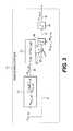
- FIG. 3is a block diagram showing a volume assurance controller of the system for circuit compliance compensation volume assured pressure control
- FIG. 4illustrates the inspiratory gas flow
- FIG. 5illustrates the final inspiratory flow command output to be used by the servo control subsystem.
- FIG. 1illustrates a patient respiratory circuit or a ventilation system that utilizes a system for circuit compliance compensated volume assured pressure control as provided herein.
- the ventilation systemincludes a circuit compliance compensated volume assured pressure control in a patient respiratory ventilator system 8 , a patient ventilator 10 , a patient circuit 20 for circulating the inspiratory gas and the expiratory gas between the ventilator 10 and a patient, the system for circuit compliance compensated volume assured pressure control 30 , and a servo control subsystem 40 for controlling operations of the ventilator 10 .
- the ventilator 10has an inspiratory port 14 and an expiratory port 16 through which the inspiratory gas and the expiratory gas are supplied to and received from the patient through the patient circuit 20 .
- An inhalation flow control valve or orificeis typically installed at the inspiratory port 14 for controlling the inspiratory flow Q INSP 23
- an exhalation valveis preferably installed at the expiratory port for controlling the open/close conditions of the expiratory port 16 .
- inspiratory and expiratory flow sensors 11 and 13are disposed adjacent to the inspiratory and expiratory ports 14 and 16 and are configured for measuring the inspiratory Q INSP 23 and expiratory flows Q EXP 27 , respectively.
- an inspiratory pressure transducer 15 and an expiratory pressure transducer 17may also be installed to measure the inspiratory and expiratory pressures P INSP 21 and P EXP , respectively.
- the patient circuit 20such as includes a Y circuit 26 , is used to connect the ventilator 10 to the patient so as to construct the respiratory circuit for circulating gas between the ventilator 10 and the patient.
- the Y circuit 20 26includes an inspiratory limb 22 with one end connected to the inspiratory port 14 and an expiratory limb 24 with one end connected to the expiratory port 16 of the ventilator 10 .
- the other ends of the inspiratory limb 22 and the expiratory limb 24merge with each other at one end of a patient Y piece 26 of which an opposite end is applied to the patient
- a flow sensor 28is preferably installed at the patient piece to directly measure the patient flow Q y 9delivered to the patient.
- the inspiratory and expiratory flow sensors 11 and 13may also be installed on the inspiratory limb 22 and the expiratory limb 24 , respectively.
- the measurable process variablesincluding the inspiratory flow Q INSP 23 , the expiratory flow Q Exp 27 , the inspiratory pressure P INSP 21 , the expiratory pressure P EXP , and positive end expiratory pressure PEEP 25 are measured according to a predetermined sampling rate. For example, in one embodiment, these process variables are sampled every 2 msec.
- the ventilator 10may further comprise a sensor processor 18 that is preferably operative to process the measured process variables or parameters, including Q INSP 23 , Q EXP 27 , P INSP 21 , P EXP and other sensor readings such as Q y 9 and calculating or computing the desired variables such as the estimated patient pressure P y 38 , estimated machine net volume VOL NET 63 , the estimated patient tidal volume VOL TID 7 , PEEP 25 and the measured patient volume V y and are sent via patient pressure data 19 for to the circuit compliance compensated volume assured pressure control system 30 .
- a sensor processor 18that is preferably operative to process the measured process variables or parameters, including Q INSP 23 , Q EXP 27 , P INSP 21 , P EXP and other sensor readings such as Q y 9 and calculating or computing the desired variables such as the estimated patient pressure P y 38 , estimated machine net volume VOL NET 63 , the estimated patient tidal volume VOL TID 7 , PEEP 25 and the
- the sensor processor 18may be configured as an individual sensor in communication with the sensors 11 , 13 , 15 , 17 and 28 and the circuit compliance compensated volume assured pressure control system 30 , integrated into the ventilator 10 , or incorporated into the system for circuit compliance compensated volume assured pressure control 30 .
- the patient pressure P y 38is defined as the expiratory pressure P EXP measured from the expiratory pressure transducer 17 during the inspiratory phase, and the average of the expiratory pressure P EXP and the inspiratory pressure P INSP 21 measured from the inspiratory pressure transducer 15 during the expiratory phase. That is, based on the following Equation (1), the sensor processor 18 is operative to compute and output the patient pressure P y to the circuit compliance compensated volume assured pressure control system 30 .
- the sensor processor 18is also operative to compute the machined delivered volume VOL NET 63 by integrating the net flow Q NET 77 defined as the flow difference between the inspiratory flow Q INSP 23 and the expiratory flow Q EXP 27 .
- the system for circuit compliance compensated volume assured pressure control 30includes a circuit compliance estimator 31 , a patient circuit volume estimator 32 , a patient volume observer 33 , a volume assurance controller 34 , and an inspiratory decelerating flow corrector 35 .
- the circuit compliance C T of the patient circuit 20can be estimated by measuring the pressure differential ⁇ P Y at various circuit volumes V CC .
- the circuit compliance estimator 31is operative to provide a relationship between the circuit volume V CC and the pressure differential ⁇ P Y based on empirical data.
- the relationshipmay be in the form of a mathematical equation of V cc and ⁇ Py or a lookup table reflecting the corresponding circuit volumes V cc for a specific circuit pressure ⁇ Py.
- V CCCKT — CMP SLP ( P y ⁇ PEEP)+ CKT — CMP INT (2); where the slope CKT_CMP SLP and the intercept CKT_CMP INT 61 are estimated by the circuit compliance estimator 31 .
- the slope CKT_CMP SLP and the intercept CKT_CMP INT of the circuit compliance estimator 31are then output to the patient circuit volume estimator 32 .
- the circuit volume estimator 32is also connected to the ventilator 10 or the sensor processor 18 for receiving patient pressure P y and the PEEP, such that the pressure differential ⁇ P y can be computed. Based on ⁇ P y , the slope CKT_CMP SLP and the intercept CKT_CMP INP , the patient circuit volume V cc can be estimated by Equation (2) and denoted as VOL CKT — EST output 62 to the patient volume observer 33 .
- the patient volume observer 33is operative to receive the measured net machine delivered volume VOL NET 63 . That is, the machine delivered net volume is derived by integrating the net flow Q NET 77 , and the estimated circuit volume VOL CKT — EST 62 is estimated by the circuit volume estimator 32 . By subtracting the estimated circuit volume VOL CKT — EST 62 from the measured machine delivered net volume VOL NET 63 derived by integrating the net flow Q NET 77 , the true tidal volume VOL TID delivered to the patient, that is, the estimated patient volume VOL TID — EST 64 , can be obtained by the patient volume observer (virtual sensor) 33 .
- the sampling intervalscan be variable according to specific conditions, requirements, or setup parameters.
- the patient flow Q y 9can be measured, and a measured patient volume VOL TID — Y 66 can be computed to facilitate volume limit of the volume assurance controller 34 so as to prevent an excessive volume compensation factor VOL TID — CTL 69 from being generated and output therefrom.
- the measured patient volume VOL TID — Y 66can also be used to replace the estimated patient volume VOL CKT — EST as a feedback patient volume used to estimate the volume compensation factor VOL TID — CTL 69 in the volume assurance controller 34 .
- the application of the measured patient volume VOL TID — Y 66will be discussed in detail below.
- the net flow Q NET 77 , the patient delivered flow Q y 9 , and the inspiratory flow Q INSP 23are continuously monitored.
- the estimated circuit volume VOL CKT—EST and the estimated patient volume VOL TID—EST 64are updated at the start expiratory phase immediately following the inspiratory phase as:
- the machine delivered net volume VOL NET 63 and the measured patient volume VOL TID Y 66will not be reset at the start of the expiratory phase. That is, the machine delivered net volume VOL NET 63 and the measured patient volume VOL TID — Y 66 are continuously updated during the expiratory phase as Equation (5).
- the inspiratory volume VOL INSPis also continuously updated as equation (5).
- the estimated patient volumeis thus updated according to the timing when the net flow Q NET crosses zero such that the entirety of the machine delivered net volume VOL NET 63 can be accounted for even when the patient breath and the machine breath are out of phase, that is, when the net flow Q NET does not cross zero at the time the machine breath is cycling to the expiratory phase.
- the volume differentialnamely, the volume error VOL TID — ERR 68
- VOL TID — ERR 68The volume differential, namely, the volume error VOL TID — ERR 68 , between the assured volume VOL ASS — SET and the estimated patient volume VOL TID — EST 64 indicates the error between the desired and actual amounts of volume delivered to the patient.
- the volume error VOL TID — ERR 68is then used by the volume assurance controller 34 for estimating a volume compensation factor in order to compensate for errors in patient volume delivery.
- the volume assurance controller 34further includes error percentage converter 341 , a gain scheduler 342 , a multiplier 343 , an integrator 344 , and a volume restrictor 345 .
- the error percentage converter 341Upon receiving the volume error VOL TID — ERR 68 , the error percentage converter 341 converts the volume error VOL TID — ERR 68 into a volume error percentage VOL PCT — ERR as:
- VOL PCT_ERR⁇ VOL TID_ERR ⁇ VOL ASS_SET ⁇ 100 ⁇ % ( 10 )
- the error percentage VOL PCT — ERRKprovides a useful indication of the ratio between the circuit compliance C T and the lung compliance C L of the patient. More specifically, when the error percentage VOL PCT — ERRK is large, it indicates that a majority of the measured machine delivered net volume VOL NET 63 is distributed to the patient circuit 20 instead of being supplied to the patient's lung. Under such circumstance, a larger amount of volume may be required to compensate for the circuit compliance C T in order to ensure that the desired assured volume VOL ASS SET as preset can be delivered to the patient's lungs.
- the gain scheduler 342is provided to generate a gain K VTID 352 according to the error percentage VOL PCT — ERR 350 for dynamically weighting the feedback volume error VOL TID — ERR , proportional to the error percentage VOL PCT — ERR
- the gain K VTJD 352is then provided to the multiplier 343 to factor the volume error VOL TID —ERR , and the weighted volume error VOL TID — ERR 353 is then outputted to the integrator 344 from which an updated volume compensation factor VOL TJD — CTL 354 can be obtained.
- VOL TID — CTLKK VTID *VOL TID — ERRK +VOL TID — CTLK — 1 (12) It will be appreciated that, at the start of the ventilation, no updated or computed volume compensation factor VOL TID — CTL 69 is available. Therefore, the volume compensation factor VOL TID — CTL 69 is initialized as:
- VOL TID_CTL 0⁇ INI_CKT ⁇ _VOL , circuit ⁇ ⁇ compliance ⁇ ⁇ compensation ⁇ ⁇ enabled 0 , circuit ⁇ ⁇ compliance ⁇ ⁇ compensation ⁇ ⁇ disabled ( 13 )
- the volume compensation factor VOL TID — CTL 69is also reset according to Equation (13) whenever any user settings of the ventilator 10 are altered. That is, any time when a new set of parameters is input to the system, the volume compensator factor, VOL TIC — CTL , will be reset according to equation (13) and updated thereafter.
- the volume assurance controller 34further comprises a volume restrictor 345 to prevent a negative circuit compliance volume compensation factor VOL TID — CTL 69 from being outputted. That is, the volume restrictor 345 restricts the output of the volume assurance controller 34 between a maximum value and zero as: VOL TID — CTLK 32 max.(VOL TID — CTLK ,0) (14)
- the measured patient volume VOL TID — Y 66can be used as a volume limit to prevent the volume assurance controller 34 from generating an excessive volume compensation factor to compensate for the circuit compliance.
- the system for circuit compliance compensated pressure control 30further comprises a volume limiter 36 operative to receive the measured patient volume VOL TID — y 66 and compare the measured patient volume VOL TID — Y 66 to the preset assured volume VOL ASS — SET .
- the volume delivery controller 34operates normally to generate the volume compensation factor VOL TID — CTL 69 based on Equations (10) to (14).
- the volume compensation factor VOL TID — CTLis output from the volume assurance controller 34 to the decelerating inspiratory flow corrector 35 , in which a maximum inspiratory peak flow Q INSP — PEAK is determined according to the volume compensation factor VOL TID — CTL , the preset assured volume VOL ASS — SET , and a preset inspiratory time T INSP — SET as:
- the inspiratory flow Q INSP — SET 72can be modulated as a function of the inspiratory time and can be computed by:
- FIG. 4illustrates the waveform of the volume assurance decelerating inspiratory flow Q INSP — SET 72 .
- a volume assurance decelerating flow command carrying data regarding the modulated volume assurance decelerating inspiratory flow Q INSP — SET 72is then outputted from the decelerating inspiratory flow corrector 35 to the servo control subsystem 40 .
- the servo control sub-system 40includes an inspiratory pressure servo controller 46 , a comparator 41 , an inspiratory flow servo controller 44 and an exhalation pressure servo controller 45 .
- an inspiratory pressure PRS INSP SET 85 captured at the beginning of every breathis preselected by the user and inputted to the inspiratory pressure servo controller 46 .
- the inspiratory pressure servo controller 46is operative to output an inspiratory pressure controller flow Q INSP — PRSCTL 82 based on the error between the preset inspiratory pressure PRS INSP — SET 85 and the estimated patient pressure P y to the comparator 41 .
- the comparator 41is then operative to output a final inspiratory flow Q INSP — DES 83 from the larger amount between the modulated volume assurance decelerating inspiratory flow Q INSP — SET 72 and the inspiratory pressure controller flow Q INSP — PRSCTL 82 to the inspiratory flow servo controller 44 .
- FIG. 5shows the final inspiratory flow Q INSP — DES 83 to be used by the inspiratory flow servo controller 44 .
- the servo control subsystem 40further comprises an exhalation pressure servo controller 45 operative to output an exhalation valve control command EV D/A 3 for closing the exhalation valve during inspiration. Its input is PRS EXH — DES 73 . That is, when the inspiratory phase starts, the exhalation valve control command EV D/A 3 is output from the exhalation pressure servo controller 45 to close the exhalation valve of the ventilator 10 .
Landscapes
- Health & Medical Sciences (AREA)
- Emergency Medicine (AREA)
- Pulmonology (AREA)
- Engineering & Computer Science (AREA)
- Anesthesiology (AREA)
- Biomedical Technology (AREA)
- Heart & Thoracic Surgery (AREA)
- Hematology (AREA)
- Life Sciences & Earth Sciences (AREA)
- Animal Behavior & Ethology (AREA)
- General Health & Medical Sciences (AREA)
- Public Health (AREA)
- Veterinary Medicine (AREA)
- Measurement Of The Respiration, Hearing Ability, Form, And Blood Characteristics Of Living Organisms (AREA)
Abstract
Description
In addition to the patient pressure Py, the
VCC=CKT—CMPSLP(Py−PEEP)+CKT—CMPINT (2);
where the slope CKT_CMPSLPand the
VOLNET
VOLCKT
VOLTID
where K is an index for indicating the currently computed variables and K-1 for indicating the previously computed variables. The sampling intervals can be variable according to specific conditions, requirements, or setup parameters.
VOLTID
VOLINSP
VOLNET
VOLTID
VOLINSP
VOLNET
VOLTID
VOLINSP
and the machine delivered
VOLNET
VOLTID
VOLNETK−1=0, VOLNETK=(QNET/60)*0.002, VOLNETK=min(VOLNETK,0)
VOLTID
In this embodiment, the measured machine delivered
VOLTID
The error percentage VOLPCT
KVTID=∫(VOLTID
The
VOLTID
It will be appreciated that, at the start of the ventilation, no updated or computed volume
The volume
VOLTID
VOLTID
VOLTID
VOLTID
When the measured
VOLTID
VOLTID
Once the maximum peak inspiratory flow QINSP
QINSP
QINSP
PRSEXH
Claims (56)
Priority Applications (1)
| Application Number | Priority Date | Filing Date | Title |
|---|---|---|---|
| US11/328,523US8474455B2 (en) | 2006-01-10 | 2006-01-10 | System and method for circuit compliance compensated volume assured pressure control in a patient respiratory ventilator |
Applications Claiming Priority (1)
| Application Number | Priority Date | Filing Date | Title |
|---|---|---|---|
| US11/328,523US8474455B2 (en) | 2006-01-10 | 2006-01-10 | System and method for circuit compliance compensated volume assured pressure control in a patient respiratory ventilator |
Publications (2)
| Publication Number | Publication Date |
|---|---|
| US20070157930A1 US20070157930A1 (en) | 2007-07-12 |
| US8474455B2true US8474455B2 (en) | 2013-07-02 |
Family
ID=38231575
Family Applications (1)
| Application Number | Title | Priority Date | Filing Date |
|---|---|---|---|
| US11/328,523Active2029-03-16US8474455B2 (en) | 2006-01-10 | 2006-01-10 | System and method for circuit compliance compensated volume assured pressure control in a patient respiratory ventilator |
Country Status (1)
| Country | Link |
|---|---|
| US (1) | US8474455B2 (en) |
Cited By (4)
| Publication number | Priority date | Publication date | Assignee | Title |
|---|---|---|---|---|
| US20120060837A1 (en)* | 2010-09-10 | 2012-03-15 | Yong Liu | Nasal intermittent mandatory ventilation (nimv) control system in a ventilator |
| US20120167884A1 (en)* | 2009-03-27 | 2012-07-05 | Erik Cardelius | Peep regulation for a breathing apparatus |
| US20130192600A1 (en)* | 2010-05-22 | 2013-08-01 | Mathias Eklund | Breathing system with flow estimation |
| US10905836B2 (en) | 2015-04-02 | 2021-02-02 | Hill-Rom Services Pte. Ltd. | Manifold for respiratory device |
Families Citing this family (41)
| Publication number | Priority date | Publication date | Assignee | Title |
|---|---|---|---|---|
| FR2858236B1 (en) | 2003-07-29 | 2006-04-28 | Airox | DEVICE AND METHOD FOR SUPPLYING RESPIRATORY GAS IN PRESSURE OR VOLUME |
| US8457706B2 (en) | 2008-05-16 | 2013-06-04 | Covidien Lp | Estimation of a physiological parameter using a neural network |
| WO2010028150A1 (en) | 2008-09-04 | 2010-03-11 | Nellcor Puritan Bennett Llc | Ventilator with controlled purge function |
| US8181648B2 (en) | 2008-09-26 | 2012-05-22 | Nellcor Puritan Bennett Llc | Systems and methods for managing pressure in a breathing assistance system |
| US8302602B2 (en) | 2008-09-30 | 2012-11-06 | Nellcor Puritan Bennett Llc | Breathing assistance system with multiple pressure sensors |
| US8113062B2 (en) | 2008-09-30 | 2012-02-14 | Nellcor Puritan Bennett Llc | Tilt sensor for use with proximal flow sensing device |
| US8434479B2 (en) | 2009-02-27 | 2013-05-07 | Covidien Lp | Flow rate compensation for transient thermal response of hot-wire anemometers |
| US8776790B2 (en) | 2009-07-16 | 2014-07-15 | Covidien Lp | Wireless, gas flow-powered sensor system for a breathing assistance system |
| US8469031B2 (en) | 2009-12-01 | 2013-06-25 | Covidien Lp | Exhalation valve assembly with integrated filter |
| US8439036B2 (en) | 2009-12-01 | 2013-05-14 | Covidien Lp | Exhalation valve assembly with integral flow sensor |
| US8439037B2 (en) | 2009-12-01 | 2013-05-14 | Covidien Lp | Exhalation valve assembly with integrated filter and flow sensor |
| US8469030B2 (en) | 2009-12-01 | 2013-06-25 | Covidien Lp | Exhalation valve assembly with selectable contagious/non-contagious latch |
| USD653749S1 (en) | 2010-04-27 | 2012-02-07 | Nellcor Puritan Bennett Llc | Exhalation module filter body |
| USD655405S1 (en) | 2010-04-27 | 2012-03-06 | Nellcor Puritan Bennett Llc | Filter and valve body for an exhalation module |
| USD655809S1 (en) | 2010-04-27 | 2012-03-13 | Nellcor Puritan Bennett Llc | Valve body with integral flow meter for an exhalation module |
| CN102892449B (en) | 2010-05-11 | 2016-04-20 | 皇家飞利浦电子股份有限公司 | Inductance in pressure support system compensates |
| US8776792B2 (en) | 2011-04-29 | 2014-07-15 | Covidien Lp | Methods and systems for volume-targeted minimum pressure-control ventilation |
| US9629971B2 (en) | 2011-04-29 | 2017-04-25 | Covidien Lp | Methods and systems for exhalation control and trajectory optimization |
| CN103071221B (en)* | 2011-10-25 | 2015-07-22 | 北京航天长峰股份有限公司 | Compliance compensation capacity guaranteeing method for anesthesia machine and respirator |
| US9364624B2 (en) | 2011-12-07 | 2016-06-14 | Covidien Lp | Methods and systems for adaptive base flow |
| WO2013098686A1 (en) | 2011-12-27 | 2013-07-04 | Koninklijke Philips Electronics N.V. | Compensation of breath delivery |
| US9498589B2 (en) | 2011-12-31 | 2016-11-22 | Covidien Lp | Methods and systems for adaptive base flow and leak compensation |
| US9144658B2 (en) | 2012-04-30 | 2015-09-29 | Covidien Lp | Minimizing imposed expiratory resistance of mechanical ventilator by optimizing exhalation valve control |
| US9289573B2 (en) | 2012-12-28 | 2016-03-22 | Covidien Lp | Ventilator pressure oscillation filter |
| USD731049S1 (en) | 2013-03-05 | 2015-06-02 | Covidien Lp | EVQ housing of an exhalation module |
| USD731065S1 (en) | 2013-03-08 | 2015-06-02 | Covidien Lp | EVQ pressure sensor filter of an exhalation module |
| USD692556S1 (en) | 2013-03-08 | 2013-10-29 | Covidien Lp | Expiratory filter body of an exhalation module |
| USD701601S1 (en) | 2013-03-08 | 2014-03-25 | Covidien Lp | Condensate vial of an exhalation module |
| USD744095S1 (en) | 2013-03-08 | 2015-11-24 | Covidien Lp | Exhalation module EVQ internal flow sensor |
| USD693001S1 (en) | 2013-03-08 | 2013-11-05 | Covidien Lp | Neonate expiratory filter assembly of an exhalation module |
| USD736905S1 (en) | 2013-03-08 | 2015-08-18 | Covidien Lp | Exhalation module EVQ housing |
| USD731048S1 (en) | 2013-03-08 | 2015-06-02 | Covidien Lp | EVQ diaphragm of an exhalation module |
| US9950135B2 (en) | 2013-03-15 | 2018-04-24 | Covidien Lp | Maintaining an exhalation valve sensor assembly |
| US10806625B1 (en)* | 2014-12-05 | 2020-10-20 | Vasper Systems, Llc | Apparatus and method for remote pressure control of a fluidic bladder |
| USD775345S1 (en) | 2015-04-10 | 2016-12-27 | Covidien Lp | Ventilator console |
| US11027081B2 (en) | 2015-07-07 | 2021-06-08 | Koninklijke Philips N.V. | Method and systems for patient airway and leak flow estimation for non-invasive ventilation |
| DE102015216895A1 (en) | 2015-09-03 | 2017-03-09 | Hamilton Medical Ag | Ventilation device with error detection for flow sensors |
| US11389608B2 (en) | 2016-09-19 | 2022-07-19 | Koninklijke Philips N.V. | Methods and systems for patient airway and leak flow estimation for non-invasive ventilation |
| DE102017101645A1 (en) | 2017-01-27 | 2018-08-02 | Ventinova Technologies B.V. | Apparatus and methods for ventilating a patient |
| EP4593033A3 (en)* | 2019-03-05 | 2025-09-10 | Fisher & Paykel Healthcare Limited | Patient attachment detection in respiratory flow therapy systems |
| US11896767B2 (en) | 2020-03-20 | 2024-02-13 | Covidien Lp | Model-driven system integration in medical ventilators |
Citations (24)
| Publication number | Priority date | Publication date | Assignee | Title |
|---|---|---|---|---|
| US4448192A (en)* | 1982-03-05 | 1984-05-15 | Hewlett Packard Company | Medical ventilator device parametrically controlled for patient ventilation |
| US4602653A (en) | 1984-11-01 | 1986-07-29 | Bear Medical Systems, Inc. | Electronically-controlled gas blending system |
| US4989456A (en) | 1989-11-06 | 1991-02-05 | Bicore Monitoring Systems | Variable area obstruction gas flow meter |
| US5038621A (en) | 1989-11-06 | 1991-08-13 | Bicore Monitoring Systems | Variable area obstruction gas flow meter |
| US5044362A (en)* | 1987-02-21 | 1991-09-03 | University Of Manitoba | Lung ventilator device |
| US5127400A (en) | 1990-03-23 | 1992-07-07 | Bird Products Corp. | Ventilator exhalation valve |
| US5178151A (en)* | 1988-04-20 | 1993-01-12 | Sackner Marvin A | System for non-invasive detection of changes of cardiac volumes and aortic pulses |
| US5197895A (en) | 1991-05-10 | 1993-03-30 | Bicore Monitoring Systems | Disposable electro-fluidic connector with data storage |
| US5303698A (en)* | 1991-08-27 | 1994-04-19 | The Boc Group, Inc. | Medical ventilator |
| US5331995A (en)* | 1992-07-17 | 1994-07-26 | Bear Medical Systems, Inc. | Flow control system for medical ventilator |
| US5429123A (en)* | 1993-12-15 | 1995-07-04 | Temple University - Of The Commonwealth System Of Higher Education | Process control and apparatus for ventilation procedures with helium and oxygen mixtures |
| US5494028A (en)* | 1986-11-04 | 1996-02-27 | Bird Products Corporation | Medical ventilator |
| US5598838A (en)* | 1995-04-07 | 1997-02-04 | Healthdyne Technologies, Inc. | Pressure support ventilatory assist system |
| US5931160A (en)* | 1995-12-08 | 1999-08-03 | Cardiopulmonary Corporation | Ventilator control system and method |
| US6015388A (en)* | 1997-03-17 | 2000-01-18 | Nims, Inc. | Method for analyzing breath waveforms as to their neuromuscular respiratory implications |
| US6305374B1 (en)* | 1989-09-22 | 2001-10-23 | Respironics, Inc. | Breathing gas delivery method and apparatus |
| USD459477S1 (en) | 2001-07-30 | 2002-06-25 | I.N. Incorporated | Ventilator housing and stand |
| USD461234S1 (en) | 2001-07-30 | 2002-08-06 | Edward G. Hanna | Exhalation water trap and filter adapter |
| US6435182B1 (en)* | 1999-03-24 | 2002-08-20 | Trustees Of Boston University | Enhanced ventilation waveform device |
| US20030097880A1 (en) | 2001-11-29 | 2003-05-29 | Ciobanu Calin I. | Multi-stage variable orifice flow obstruction sensor |
| US20030106554A1 (en) | 2001-11-30 | 2003-06-12 | De Silva Adrian D. | Gas identification system and volumetric ally correct gas delivery system |
| US6968842B1 (en)* | 2002-04-03 | 2005-11-29 | Ric Investments, Inc. | Measurement of a fluid parameter in a pressure support system |
| US20070089738A1 (en)* | 2005-10-11 | 2007-04-26 | Soliman Ihab S | System and method for circuit compliance compensated volume control in a patient respiratory ventilator |
| US20070101992A1 (en)* | 2005-11-09 | 2007-05-10 | Viasys Manufacturing, Inc. | System and method for circuit compliance compensated pressure-regulated volume control in a patient respiratory ventilator |
- 2006
- 2006-01-10USUS11/328,523patent/US8474455B2/enactiveActive
Patent Citations (29)
| Publication number | Priority date | Publication date | Assignee | Title |
|---|---|---|---|---|
| US4448192A (en)* | 1982-03-05 | 1984-05-15 | Hewlett Packard Company | Medical ventilator device parametrically controlled for patient ventilation |
| US4602653A (en) | 1984-11-01 | 1986-07-29 | Bear Medical Systems, Inc. | Electronically-controlled gas blending system |
| US5494028A (en)* | 1986-11-04 | 1996-02-27 | Bird Products Corporation | Medical ventilator |
| US5044362A (en)* | 1987-02-21 | 1991-09-03 | University Of Manitoba | Lung ventilator device |
| US5107830A (en)* | 1987-02-21 | 1992-04-28 | University Of Manitoba | Lung ventilator device |
| US5178151A (en)* | 1988-04-20 | 1993-01-12 | Sackner Marvin A | System for non-invasive detection of changes of cardiac volumes and aortic pulses |
| US6305374B1 (en)* | 1989-09-22 | 2001-10-23 | Respironics, Inc. | Breathing gas delivery method and apparatus |
| US6948497B2 (en)* | 1989-09-22 | 2005-09-27 | Ric Investments, Inc. | Breathing gas delivery method and apparatus |
| US7100607B2 (en)* | 1989-09-22 | 2006-09-05 | Ric Investments, Inc. | Breathing gas delivery method and apparatus |
| US4989456A (en) | 1989-11-06 | 1991-02-05 | Bicore Monitoring Systems | Variable area obstruction gas flow meter |
| US5038621A (en) | 1989-11-06 | 1991-08-13 | Bicore Monitoring Systems | Variable area obstruction gas flow meter |
| US5127400A (en) | 1990-03-23 | 1992-07-07 | Bird Products Corp. | Ventilator exhalation valve |
| US5197895A (en) | 1991-05-10 | 1993-03-30 | Bicore Monitoring Systems | Disposable electro-fluidic connector with data storage |
| US5405269A (en) | 1991-05-10 | 1995-04-11 | Stupecky; Josef J. | Disposable electro-fluidic connector with data storage |
| US5303698A (en)* | 1991-08-27 | 1994-04-19 | The Boc Group, Inc. | Medical ventilator |
| US5331995A (en)* | 1992-07-17 | 1994-07-26 | Bear Medical Systems, Inc. | Flow control system for medical ventilator |
| US5429123A (en)* | 1993-12-15 | 1995-07-04 | Temple University - Of The Commonwealth System Of Higher Education | Process control and apparatus for ventilation procedures with helium and oxygen mixtures |
| US5598838A (en)* | 1995-04-07 | 1997-02-04 | Healthdyne Technologies, Inc. | Pressure support ventilatory assist system |
| US5927274A (en)* | 1995-04-07 | 1999-07-27 | Healthdyne Technologies, Inc. | Pressure support ventilatory assist system |
| US5931160A (en)* | 1995-12-08 | 1999-08-03 | Cardiopulmonary Corporation | Ventilator control system and method |
| US6015388A (en)* | 1997-03-17 | 2000-01-18 | Nims, Inc. | Method for analyzing breath waveforms as to their neuromuscular respiratory implications |
| US6435182B1 (en)* | 1999-03-24 | 2002-08-20 | Trustees Of Boston University | Enhanced ventilation waveform device |
| USD459477S1 (en) | 2001-07-30 | 2002-06-25 | I.N. Incorporated | Ventilator housing and stand |
| USD461234S1 (en) | 2001-07-30 | 2002-08-06 | Edward G. Hanna | Exhalation water trap and filter adapter |
| US20030097880A1 (en) | 2001-11-29 | 2003-05-29 | Ciobanu Calin I. | Multi-stage variable orifice flow obstruction sensor |
| US20030106554A1 (en) | 2001-11-30 | 2003-06-12 | De Silva Adrian D. | Gas identification system and volumetric ally correct gas delivery system |
| US6968842B1 (en)* | 2002-04-03 | 2005-11-29 | Ric Investments, Inc. | Measurement of a fluid parameter in a pressure support system |
| US20070089738A1 (en)* | 2005-10-11 | 2007-04-26 | Soliman Ihab S | System and method for circuit compliance compensated volume control in a patient respiratory ventilator |
| US20070101992A1 (en)* | 2005-11-09 | 2007-05-10 | Viasys Manufacturing, Inc. | System and method for circuit compliance compensated pressure-regulated volume control in a patient respiratory ventilator |
Cited By (10)
| Publication number | Priority date | Publication date | Assignee | Title |
|---|---|---|---|---|
| US20120167884A1 (en)* | 2009-03-27 | 2012-07-05 | Erik Cardelius | Peep regulation for a breathing apparatus |
| US9333312B2 (en)* | 2009-03-27 | 2016-05-10 | Maquet Critical Care Ab | Peep regulation for a breathing apparatus |
| US20130192600A1 (en)* | 2010-05-22 | 2013-08-01 | Mathias Eklund | Breathing system with flow estimation |
| US9295796B2 (en)* | 2010-05-22 | 2016-03-29 | Maquet Critical Care Ab | Breathing system with flow estimation |
| US20120060837A1 (en)* | 2010-09-10 | 2012-03-15 | Yong Liu | Nasal intermittent mandatory ventilation (nimv) control system in a ventilator |
| US9370633B2 (en)* | 2010-09-10 | 2016-06-21 | Carefusion 207, Inc. | Nasal intermittent mandatory ventilation (NIMV) control system in a ventilator |
| US9561342B2 (en) | 2010-09-10 | 2017-02-07 | Carefusion 207, Inc. | Nasal intermittent mandatory ventilation (NIMV) control system in a ventilator |
| US10905836B2 (en) | 2015-04-02 | 2021-02-02 | Hill-Rom Services Pte. Ltd. | Manifold for respiratory device |
| US10905837B2 (en) | 2015-04-02 | 2021-02-02 | Hill-Rom Services Pte. Ltd. | Respiratory therapy cycle control and feedback |
| US11992611B2 (en) | 2015-04-02 | 2024-05-28 | Hill-Rom Services Pte. Ltd. | Respiratory therapy apparatus control |
Also Published As
| Publication number | Publication date |
|---|---|
| US20070157930A1 (en) | 2007-07-12 |
Similar Documents
| Publication | Publication Date | Title |
|---|---|---|
| US8474455B2 (en) | System and method for circuit compliance compensated volume assured pressure control in a patient respiratory ventilator | |
| EP1933911B1 (en) | System for circuit compliance compensated volume control in a patient respiratory ventilator | |
| US8453644B2 (en) | System and method for circuit compliance compensated pressure-regulated volume control in a patient respiratory ventilator | |
| US11497869B2 (en) | Methods and systems for adaptive base flow | |
| CA2421561C (en) | Adaptive inverse control of pressure based ventilation | |
| US20090293876A1 (en) | System and Method for Adaptive High Frequency Flow Interrupter Control In A Patient Repiratory Ventilator | |
| US9675771B2 (en) | Methods and systems for leak estimation | |
| US8448641B2 (en) | Leak-compensated proportional assist ventilation | |
| US8272380B2 (en) | Leak-compensated pressure triggering in medical ventilators | |
| US8256418B2 (en) | Determination of leak during CPAP treatment | |
| US6820613B2 (en) | Process and device for controlling the breathing gas supply | |
| RU2722432C1 (en) | Method of pressure and gas mixture control for non-invasive artificial lung ventilation | |
| US20100147303A1 (en) | Determination of patient circuit disconnect in leak-compensated ventilatory support | |
| EP2575942B1 (en) | Breathing system with flow estimation | |
| WO2009123981A1 (en) | Leak-compensated proportional assist ventilation | |
| US11389608B2 (en) | Methods and systems for patient airway and leak flow estimation for non-invasive ventilation | |
| US11027081B2 (en) | Method and systems for patient airway and leak flow estimation for non-invasive ventilation | |
| EP3397330B1 (en) | Device and method for controlling ventilatory assist | |
| US10434270B2 (en) | Compensation of breath delivery | |
| US20220096764A1 (en) | Synchronized high-flow system |
Legal Events
| Date | Code | Title | Description |
|---|---|---|---|
| AS | Assignment | Owner name:VIASYS MANUFACTURING, INC., PENNSYLVANIA Free format text:ASSIGNMENT OF ASSIGNORS INTEREST;ASSIGNORS:SOLIMAN, IHAB S.;DUQUETTE, STEVEN;REEL/FRAME:017444/0574 Effective date:20060109 | |
| AS | Assignment | Owner name:CAREFUSION 207, INC., CALIFORNIA Free format text:CHANGE OF NAME;ASSIGNOR:CARDINAL HEALTH 207, INC.;REEL/FRAME:025135/0305 Effective date:20090729 Owner name:CARDINAL HEALTH 207, INC., CALIFORNIA Free format text:CHANGE OF NAME;ASSIGNOR:VIASYS MANUFACTURING, INC.;REEL/FRAME:025135/0297 Effective date:20071016 | |
| STCF | Information on status: patent grant | Free format text:PATENTED CASE | |
| FPAY | Fee payment | Year of fee payment:4 | |
| AS | Assignment | Owner name:BANK OF AMERICA, N.A., AS COLLATERAL AGENT, NORTH Free format text:FIRST LIEN SECURITY AGREEMENT;ASSIGNOR:CAREFUSION 207, INC.;REEL/FRAME:045968/0497 Effective date:20180416 Owner name:WILMINGTON TRUST, NATIONAL ASSOCIATION, AS COLLATE Free format text:SECOND LIEN SECURITY AGREEMENT;ASSIGNOR:CAREFUSION 207, INC.;REEL/FRAME:045969/0482 Effective date:20180416 | |
| AS | Assignment | Owner name:WILMINGTON TRUST, NATIONAL ASSOCIATION, MINNESOTA Free format text:SECURITY INTEREST;ASSIGNOR:CAREFUSION 207, INC.;REEL/FRAME:049109/0656 Effective date:20190503 | |
| MAFP | Maintenance fee payment | Free format text:PAYMENT OF MAINTENANCE FEE, 8TH YEAR, LARGE ENTITY (ORIGINAL EVENT CODE: M1552); ENTITY STATUS OF PATENT OWNER: LARGE ENTITY Year of fee payment:8 | |
| AS | Assignment | Owner name:VYAIRE MEDICAL 207, INC., ILLINOIS Free format text:CHANGE OF NAME;ASSIGNOR:CAREFUSION 207, INC.;REEL/FRAME:059852/0577 Effective date:20210401 | |
| AS | Assignment | Owner name:VYAIRE MEDICAL 211, INC., ILLINOIS Free format text:MERGER;ASSIGNOR:VYAIRE MEDICAL 207, INC.;REEL/FRAME:061329/0785 Effective date:20220411 | |
| AS | Assignment | Owner name:ZOLL MEDICAL CORPORATION, MASSACHUSETTS Free format text:ASSIGNMENT OF ASSIGNORS INTEREST;ASSIGNOR:VYAIRE MEDICAL 211, INC.;REEL/FRAME:069454/0907 Effective date:20241011 | |
| AS | Assignment | Owner name:ZOLL MEDICAL CORPORATION, MASSACHUSETTS Free format text:RELEASE BY SECURED PARTY;ASSIGNOR:VYAIRE MEDICAL, INC., ET AL.'S CREDITORS;REEL/FRAME:069635/0201 Effective date:20240903 | |
| MAFP | Maintenance fee payment | Free format text:PAYMENT OF MAINTENANCE FEE, 12TH YEAR, LARGE ENTITY (ORIGINAL EVENT CODE: M1553); ENTITY STATUS OF PATENT OWNER: LARGE ENTITY Year of fee payment:12 |