US8474221B1 - Telescoping fiberglass utility pole - Google Patents
Telescoping fiberglass utility poleDownload PDFInfo
- Publication number
- US8474221B1 US8474221B1US13/494,539US201213494539AUS8474221B1US 8474221 B1US8474221 B1US 8474221B1US 201213494539 AUS201213494539 AUS 201213494539AUS 8474221 B1US8474221 B1US 8474221B1
- Authority
- US
- United States
- Prior art keywords
- pole
- section
- center
- pole section
- protruding
- Prior art date
- Legal status (The legal status is an assumption and is not a legal conclusion. Google has not performed a legal analysis and makes no representation as to the accuracy of the status listed.)
- Expired - Fee Related
Links
Images


Classifications
- E—FIXED CONSTRUCTIONS
- E04—BUILDING
- E04C—STRUCTURAL ELEMENTS; BUILDING MATERIALS
- E04C3/00—Structural elongated elements designed for load-supporting
- E04C3/30—Columns; Pillars; Struts
- E04C3/36—Columns; Pillars; Struts of materials not covered by groups E04C3/32 or E04C3/34; of a combination of two or more materials
- E—FIXED CONSTRUCTIONS
- E04—BUILDING
- E04H—BUILDINGS OR LIKE STRUCTURES FOR PARTICULAR PURPOSES; SWIMMING OR SPLASH BATHS OR POOLS; MASTS; FENCING; TENTS OR CANOPIES, IN GENERAL
- E04H12/00—Towers; Masts or poles; Chimney stacks; Water-towers; Methods of erecting such structures
- E04H12/02—Structures made of specified materials
- E—FIXED CONSTRUCTIONS
- E04—BUILDING
- E04H—BUILDINGS OR LIKE STRUCTURES FOR PARTICULAR PURPOSES; SWIMMING OR SPLASH BATHS OR POOLS; MASTS; FENCING; TENTS OR CANOPIES, IN GENERAL
- E04H12/00—Towers; Masts or poles; Chimney stacks; Water-towers; Methods of erecting such structures
- E04H12/18—Towers; Masts or poles; Chimney stacks; Water-towers; Methods of erecting such structures movable or with movable sections, e.g. rotatable or telescopic
- E04H12/182—Towers; Masts or poles; Chimney stacks; Water-towers; Methods of erecting such structures movable or with movable sections, e.g. rotatable or telescopic telescopic
- H—ELECTRICITY
- H02—GENERATION; CONVERSION OR DISTRIBUTION OF ELECTRIC POWER
- H02G—INSTALLATION OF ELECTRIC CABLES OR LINES, OR OF COMBINED OPTICAL AND ELECTRIC CABLES OR LINES
- H02G7/00—Overhead installations of electric lines or cables
- H02G7/20—Spatial arrangements or dispositions of lines or cables on poles, posts or towers
Definitions
- the present inventionrelates to environmentally friendly fiberglass utility poles.
- Pentachlorophenolis widely-used wood preservative that is normally dissolved in a petroleum carrier. It is the most commonly used preservative system utilized by North American utilities. Chromated Copper Arsenate (CCA) is water-borne treatment that offers a wide range of advantages for treated lumber, timber and poles; clean; odorless; paintable.
- Creosoteis an oil-based wood preservative blended from the distillation of coal tar and comprised of more than 200 major constituents. Used in industrial applications, such as railroad ties, piling (both salt water and fresh water), and for utility poles.
- Copper Azole (CA-B)is a water-borne copper based wood preservative with an organic co-biocide (Tebuconazol). Similar in color, to CCA-C, odorless, clean, paintable or stainable. Copper Azole is approved by the American Wood Preservers Association for use on Western Red Cedar and Southern Yellow Pine utility poles.
- the present inventionprovides an environmentally friendly fiberglass utility pole having added strength as compared to standard wooden poles.
- the present utility poleis made from a plurality of telescoping sections.
- An advantage of the present telescoping sectional designis that it is lighter and less bulky to deliver to a jobsite (compared to a standard large, single solid wooden utility pole).
- the present utility poleis made from environmentally friendly materials, including but not limited to fiberglass. These environmentally friendly materials offer the advantages of being safe, aesthetically pleasing, resistant to damage and corrosion (from weather, animals, insects, etc.).
- the present utility poleis light weight, high strength, corrosion/rot resistant, non-conductive, electro-magnetically transparent, dimensionally stabile, low temperature capable, and aesthetically pleasing. In addition, it can be made in different colors.
- another advantage of the present inventionis that the individual telescoping sections are made of a cross sectional shape having a repeating pattern of protruding and intruding regions around its circumference to provide added strength.
- the present telescoping utility poleprovides a utility pole assembly having a strength comparable to that of a standard large, uniform diameter pole. Specifically, the entire length of the present utility pole need is not made to the same large diameter as would be the case when dealing with a solid wooden pole of uniform diameter. Instead, the upper and lower ends of the present invention utility pole are narrower, whereas the mid sections are somewhat larger in diameter. As will be explained, this strength advantage is due to the inner sections being reinforced by outer telescoping pole sections received thereover).
- the utility polecomprises three pole sections.
- embodiments having additional pole sectionsare also described.
- the preferred pattern of protruding and intruding regions around the circumference of the pole cross sectionsbecome progressively less pronounced moving farther outward from the center of the assembly.
- Embodiments with no cross sectional protruding and intruding regionsare also described, and are encompassed in the present invention.
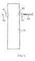
- FIG. 1is a side elevation view of a preferred embodiment of the telescoping utility pole. A partial cut out section is included to highlight the three pole sections fitting together.
- FIG. 2is a sectional plan view taken along line 2 - 2 in FIG. 1 .
- FIG. 3is a sectional plan view taken along line 3 - 3 in FIG. 1 .
- FIG. 4is a side elevation view of the system used to fasten the three pole sections together.
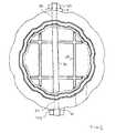
- FIG. 5is a sectional plan view of the fastening system of FIG. 4 , showing the fastener system holding the telescoping pole sections together.
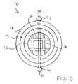
- FIG. 6is an embodiment similar to FIG. 3 , but wherein the pole sections do not have protruding and intruding regions, but are instead circular.
- FIG. 7is a view similar to FIG. 1 , but showing a telescoping utility pole having four pole sections.
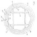
- FIG. 8is a sectional plan view taken along line 8 - 8 in FIG. 7 .
- Wooden utility polesare heavy and bulky and therefore hard to move and install. In addition, they need to be treated with chemicals that are harmful to the environment and poisonous to humans. Moreover, they are subject to wear and tear (due to weather and insects), and thus have to typically be replaced every ten years or so.
- a further advantage of the present inventionis that the cross sections of the telescoping utility pole sections preferably are not simply circular. Instead, the cross sectional shape of each of the pole sections provides additional bending strength beyond that that would be provided by a simple circular or annular cross sectional shape. Such additional strength may be required for standard wind loading and when components including connectors and wires are mounted onto the top of the utility pole.
- the preferred illustrated cross sectional shapeprovides a system in which the telescoping poles can be interlocked together with no danger of rotation or movement between the pole sections.
- FIG. 1illustrates a preferred embodiment of the present invention. It is to be understood that the present invention can be built to various dimensions, all keeping within the scope of the invention.
- the present inventioncomprises three sections, being an inner section, a center section received around the inner section and an outer section received around the center section.
- the inner sectionis hollow, however, the present invention also covers embodiments with solid inner sections.
- the center sectionis received around the inner section.
- an outer sectionis fit around the center section.
- utility pole 10comprises an inner section 12 , a center section 14 and an outer section 16 . It is to be understood that the present invention is not limited to any particular dimensions. The final assembled utility pole could easily have a lifetime exceeding 100 years.
- sections 12 , 14 and 16each have protruding regions 12 A, 14 A and 16 A (i.e.: areas that stick radially outwards), and intruding regions 12 B, 14 B and 16 B (i.e.: areas that stick radially inwards).
- Inner pole section 12is received into center pole section 14 such that sections 12 A mate, match up with or fit into sections 14 A.
- Sections 12 Bmate, match up with or fit into sections 14 B.
- center pole section 14is received into outer pole section 16 such that sections 14 A mate, match up with or fit into sections 16 A.
- Sections 14 Bmate, match up with or fit into sections 16 B.
- pole sections 12 , 14 and 16are all shown as having a similarly dimensioned cross section (e.g.: a repeating pattern of protruding and intruding regions 12 A/ 14 A/ 16 A and 12 B/ 14 B/ 16 B, respectively around the circumference of the cross section).
- pole section 12need not be hollow.
- pole section 16can have a more rounded outer surface.
- the degree to which the protruding and intruding regions existcan be progressively less pronounced moving outwards from the center of the assembly. For example, regions 12 A/ 12 B may be more pronounced than regions 14 A and 14 B.
- regions 14 A/ 14 Bmay be more pronounced than regions 16 A and 16 B.
- the exterior of the pole assemblycan be smoother than the interior sections. Stated another way, the protrusions and intrusions can be become less and less pronounced the farther outward one moves away from the center of the assembly. In fact, the outer surface of the entire assembly can even be smooth.
- one or more additional pole sectionscan even be added outside of pole section 16 . Each additional outer pole section can be smoother than the last. What is important within the scope of the present invention is that the outer surface of pole section 12 mates with the inner surface of pole section 14 and that the outer surface of pole section 14 mates with the inner surface of pole section 16 . The same is true when additional section(s) are added around section 16 .
- inner pole section 12is preferably longer than center pole section 14 and the center pole section 14 is preferably longer than outer pole section 16 .
- outer section 16surrounds the middle but not the ends of center section 14
- the center section 14surrounds the middle but not the ends of inner section 12 .
- the narrow top endensures that the pole is not top heavy.
- the bottom endcan be narrower (i.e.: not reinforced all the way to its bottom by pole sections 14 and 16 ) because the bottom end of pole assembly 10 is inserted into the ground G. (Typically, the bottom 10% plus two feet of a utility pole are inserted into the ground).
- each of the inner 12 , center 14 and outer 16 pole sectionsare made of fiberglass.
- theymay be made of a suitable thermoset resin, including but not limited to polyvinyl chloride.
- These pole sections 12 , 14 and 16can be made by pultrusion or extrusion. “Extrusion” is a manufacturing process where a material is pushed and/or drawn through a die to create long objects of a fixed cross-section. Hollow sections are usually extruded by placing a pin or mandrel in the die. Extrusion may be continuous (e.g., producing indefinitely long material) or semi-continuous (e.g., repeatedly producing many shorter pieces). Some extruded materials are hot drawn and others may be cold drawn.
- the feedstockmay be forced through the die by various methods: by an auger, which can be single or twin screw, powered by an electric motor; by a ram, driven by hydraulic pressure, oil pressure or in other specialized processes such as rollers inside a perforated drum for the production of many simultaneous streams of material.
- Plastic extrusioncommonly uses plastic chips, which are heated and extruded in the liquid state, then cooled and solidified as it passes through the die.
- Pultrusionis a manufacturing process for producing continuous lengths of materials.
- Pultrusion raw materialsinclude a liquid resin mixture (e.g., containing resin, fillers and specialized additives) and reinforcing fibers (e.g., fiberglass, composite materials, etc.).
- the processinvolves pulling these raw materials (rather than pushing as is the case in extrusion) through a heated steel forming die using a continuous pulling device.
- the reinforcement materialsare in continuous forms such as rolls of fiberglass mat or doffs of fiberglass roving.
- the gelation (or hardening) of the resinis initiated by the heat from the die and a rigid, cured profile is formed that corresponds to the shape of the die.
- protruded laminatesThere are also protruded laminates. Most pultruded laminates are formed using rovings aligned down the major axis of the part. Various continuous strand mats, fabrics (e.g., braided, woven and knitted), and texturized or bulked rovings are used to obtain strength in the cross axis or transverse direction.
- rovingsaligned down the major axis of the part.
- fabricse.g., braided, woven and knitted
- texturized or bulked rovingsare used to obtain strength in the cross axis or transverse direction.
- the pultriusion processis normally continuous and highly automated.
- Reinforcement materialssuch as roving, mat or fabrics, are positioned in a specific location using preforming shapers or guides to form a pultruson.
- the reinforcementsare drawn through a resin bath where the material is thoroughly coated or impregnated with a liquid thermosetting resin.
- the resin-saturated reinforcementsenter a heated metal pultrusion die.
- the dimensions and shape of the diedefine the finished part being fabricated.
- heatis transferred initiated by precise temperature control to the reinforcements and liquid resin.
- the heat energyactivates the curing or polymerization of the thermoset resin changing it from a liquid to a solid.
- the solid laminateemerges from the pultrusion die to the exact shape of the die cavity.
- the laminatesolidifies when cooled and it is continuously pulled through the pultrusion machine and cut to the desired length.
- the processis driven by a system of caterpillar or tandem pullers located between the die exit and the cut-off mechanism.
- the pultrusion resinsinclude bisphenol-a epichlorohydrin-based vinyl esters.
- the resinsinclude polyesters including isophthalic, orthophthalic, propylene-maleate, fire resistant, and high cross-link density.
- the present inventionis not limited to these resins and other resins can be used to practice the invention.
- the pultrusionsinclude re-enforcing fibers comprising, fiberglass fibers, composite fibers, etc.
- re-enforcing fiberscomprising, fiberglass fibers, composite fibers, etc.
- present inventionis not limited to these resins and other resins can be used to practice the invention.
- thermoset resinOne resin used in fiberglass pultrusions is a thermoset resin.
- the resin used in Polyvinyl Chloride (PVC) pultrusionsare typical thermoplastic resins.
- PVCPolyvinyl Chloride
- the thermoset resins and re-enforcing fibersform a new inert material that is impervious to temperature.
- Pultruded fiberglass physical propertiesdo not change through the full temperature cycle up to temperatures of about 200 degrees Fahrenheit (.degree. F).
- PVC resinstypically become unstable at temperatures greater than 155.degree. F.
- Pultrusionsinclude but are not limited to, structures comprising: (1) HIGH STRENGTH—typically stronger than structural steel on a pound-for-pound basis; (2) LIGHTWEIGHT—Pultrusions are 20-25% the weight of steel and 70% the weight of aluminum.
- Pultruded productsare easily transported, handled and lifted into place; (3) CORROSION/ROT RESISTANT—Pultruded products will not rot and are impervious to a broad range of corrosive elements; (4) NON-CONDUCTIVE—fiberglass reinforced pultrusions have low thermal conductivity and are electrically non-conductive; (5) ELECTRO-MAGNETIC TRANSPARENT—Pultruded products are transparent to radio waves, microwaves and other electromagnetic frequencies; (6) DIMENSIONAL STABILE—The coefficient of thermal expansion of pultruded products is slightly less than steel and significantly less than aluminum; (7) LOW TEMPERATURE CAPABLE—FiberGlass fiber reinforced pultrusions exhibit excellent mechanical properties at very low temperatures, even ⁇ 70.degree.
- AESTHETICLY PLEASINGPultruded profiles are pigmented throughout the thickness of the part and can be made to virtually any desired custom color. Special surfacing veils are also available to create special surface appearances such as wood grain, marble, granite, etc.
- pole sections 12 , 14 and 16comprise extruded plastic materials including, but not limited to, Polyvinyl Chloride (PVC), Acrylonitrile Butadiene Styrene (ABS), High Impact Polypropylene (HIP), Polypropylene, High-Density Polyethylene (HDPE), Polycarbonate, Polyethylene Terephthalate Glycol (PETG), Nylon, Fiber reinforced Polypropylene, Fiber Reinforced Plystyrene and other types of plastics.
- the pole sectionscomprise composite materials.
- the pole sectionscomprise recycled plastic materials.
- the pole sectionscan be made in different colors (e.g., red, green, yellow, blue, brown, etc.) to be aesthetically pleasing.
- Such plural different colorsmay blend in with a natural environmental setting or a pre-determined design scheme.
- a new subdivisionmay include only blue extruded utility poles, while a boat dock may include only high visibility orange poles.
- the present inventionis not limited to these colors and other colors can be used to practice the invention.
- an inner pole section 12is hollow, an optional unibeam section 20 is received down into at least a portion of inner pole section 12 .
- Unibeam 20may be used to give additional strength to pole assembly 20 .
- various wires and electrical componentscan be passed up and down through the center of the pole through unibeam 20 . (Alternatively, the wires can be formed directly into the body of the pole sections themselves.
- unibeam 20is short and is only included at the top end of the pole assembly. However, the present invention covers embodiments in which unibeam 20 extends part or all of the way down thorough the interior of pole section 12 .
- Communications wirese.g., fiber optic, copper, coaxial cable, etc.
- antenna wirescan be run through the hollow core of pole section 12 or unibeam 20 to connect to other communications wires buried underground in dirt or sub-terrain pipes or tunnels. This avoids connecting unsightly communications wires between two or more extruded structure 12 and protects the communications wires or antenna wires from damage by the weather and animals
- center pole section 14can be is caulked direction onto the outside of inner pole section 12 at location 15 .
- top end of outer section 16can be is caulked directly onto the outside of center pole section 14 at location 17 . This keeps rain from penetrating between the pole sections. (Note: the bottom contact points need not be caulked since not caulking would leave small passageways for drainage).
- FIGS. 4 and 5illustrate systems for fastening poles together. Specifically, an interior tube 30 passes through the structure. Then, a nut and bolt assembly 40 passes through tube 20 . Bushings 41 are also included. The advantage of tube 30 is that it prevents over tightening from distorting the outer shape of the pole assembly. Bushings 41 also distribute the tightening load from nut and bolt 40 around a portion of the outside of outer pole section 16 .
- FIG. 5illustrates the embodiment of FIG. 3 , but with tubing 30 and nut and bolt assembly 40 holding the various pole sections 12 , 14 and 16 together. As can be seen, tube 30 and nut and bolt assembly 40 also pass through unibeam section 20 . It is to be understood that tube 30 , nut and bolt assembly 40 and bushings 41 can be used at various locations along the vertical length of pole assembly 10 (thereby just holding sections 12 and 14 together, or holding sections 12 , 14 and 16 together), as desired.
- pole sections 12 , 14 and 16gives excellent resistance to wind shear forces.
- additional filaments or webbingincluding fiberglass, plastic, ester, polyester, nylon, and composite materials may be added internally or externally to add strength.
- FIG. 6covers the embodiment of the invention in which the pole sections do not have protruding and intruding regions, but are instead circular. It is to be understood that the present invention encompasses pole sections having any particular cross section.
- FIGS. 7 and 8show an embodiment of the invention in which a fourth pole section 18 is included. Pole section 18 is received around pole section 16 . It is to be understood that the present invention covers embodiments having more than three pole sections (i.e.: with one or more additional sections 18 , etc. being added around section 16 ). The present invention is therefore understood to include embodiments having two, three, four or more pole section received around one another.
- the preferred pattern of protruding and intruding regions around the circumference of the pole cross sectionscan become progressively less pronounced moving farther outward from the center of the assembly. Specifically, regions 12 A/ 12 B are more pronounced than regions 14 A/ 14 B. Regions 14 A/ 14 B are in turn more pronounced than regions 16 A/ 16 B. Finally, the protruding and intruding regions 18 A/ 18 B are hardly seen at all. In fact, the exterior surface of pole section 18 may be completely smooth.
Landscapes
- Engineering & Computer Science (AREA)
- Architecture (AREA)
- Civil Engineering (AREA)
- Structural Engineering (AREA)
- Life Sciences & Earth Sciences (AREA)
- Chemical & Material Sciences (AREA)
- Materials Engineering (AREA)
- Wood Science & Technology (AREA)
- Fencing (AREA)
Abstract
Description
Claims (23)
Priority Applications (1)
| Application Number | Priority Date | Filing Date | Title |
|---|---|---|---|
| US13/494,539US8474221B1 (en) | 2012-01-20 | 2012-06-12 | Telescoping fiberglass utility pole |
Applications Claiming Priority (2)
| Application Number | Priority Date | Filing Date | Title |
|---|---|---|---|
| US201261589285P | 2012-01-20 | 2012-01-20 | |
| US13/494,539US8474221B1 (en) | 2012-01-20 | 2012-06-12 | Telescoping fiberglass utility pole |
Publications (2)
| Publication Number | Publication Date |
|---|---|
| US8474221B1true US8474221B1 (en) | 2013-07-02 |
| US20130186039A1 US20130186039A1 (en) | 2013-07-25 |
Family
ID=48671069
Family Applications (1)
| Application Number | Title | Priority Date | Filing Date |
|---|---|---|---|
| US13/494,539Expired - Fee RelatedUS8474221B1 (en) | 2012-01-20 | 2012-06-12 | Telescoping fiberglass utility pole |
Country Status (1)
| Country | Link |
|---|---|
| US (1) | US8474221B1 (en) |
Cited By (9)
| Publication number | Priority date | Publication date | Assignee | Title |
|---|---|---|---|---|
| CN105839849A (en)* | 2016-03-23 | 2016-08-10 | 四川相哥建材有限责任公司 | Casing-pipe marble pillar body product and production method thereof |
| WO2016124953A1 (en)* | 2015-02-04 | 2016-08-11 | Composite Technologies Ltd | Modular fiber reinforced plastic poles |
| US9702162B2 (en) | 2015-02-06 | 2017-07-11 | Trident Industries, LLC | Pultruded or extruded cross arm structures for utility poles |
| CN107191759A (en)* | 2017-06-13 | 2017-09-22 | 台州正空泵业有限公司 | One kind is easy to adjustable type support meanss |
| US20180202183A1 (en)* | 2017-01-13 | 2018-07-19 | Quanta Associates, L.P. | Pole setting device and method of using the same |
| US10302289B2 (en)* | 2017-06-09 | 2019-05-28 | Kearney-National Inc. | Lighting pole with isolated axial chambers |
| US10731372B1 (en)* | 2019-08-26 | 2020-08-04 | Dustin Kyle Nolen | Small cell fiberglass communications utility pole |
| US10851561B2 (en)* | 2018-10-26 | 2020-12-01 | ARV Ventures, LLC | Structural footer |
| US20210396034A1 (en)* | 2018-09-28 | 2021-12-23 | General Electric Company | Method for manufacturing a telescoping wind turbine tower structure |
Families Citing this family (4)
| Publication number | Priority date | Publication date | Assignee | Title |
|---|---|---|---|---|
| US9837698B2 (en) | 2014-05-30 | 2017-12-05 | Enersphere Communications Llc | Small cell communications pole, system, and method |
| CA3228953A1 (en)* | 2017-01-06 | 2018-07-12 | Valmont Industries, Inc. | Improved cross arm support structure |
| EP3682280A4 (en) | 2017-09-15 | 2021-05-26 | Commscope Technologies LLC | CONNECTIVITY OF AN INTELLIGENT MASTER |
| US12270430B2 (en) | 2019-10-15 | 2025-04-08 | MJ Engineering LLC | Layered multi-body support structure |
Citations (126)
| Publication number | Priority date | Publication date | Assignee | Title |
|---|---|---|---|---|
| US3054783A (en) | 1958-10-22 | 1962-09-18 | Dow Chemical Co | Molding grade copolymers and process for preparing the same |
| GB928348A (en) | 1960-12-01 | 1963-06-12 | A C Ford Ltd | Improvements relating to columns for supporting lamps for street lighting purposes |
| US3154200A (en) | 1962-05-14 | 1964-10-27 | Gilson Brothers Co | Pole handling device |
| US3236398A (en) | 1963-10-07 | 1966-02-22 | William E Thiermann | Apparatus for pole setting |
| US3495370A (en)* | 1966-11-28 | 1970-02-17 | Vagbelysnign Ab | Telescopic mast |
| US3564804A (en)* | 1969-03-11 | 1971-02-23 | Arlo Inc | Method of aligning and longitudinally locking cylindrical telescoping sections of increasingly smaller diameter |
| US3574104A (en) | 1968-01-24 | 1971-04-06 | Plastigage Corp | Glass fiber constructional member |
| US3712005A (en) | 1969-12-15 | 1973-01-23 | Aztec Mfg Co | Extrusions for partitions, walls and enclosures |
| US3776650A (en) | 1970-08-19 | 1973-12-04 | Zenhaeusern Heinrich | Connecting device |
| US3813837A (en) | 1972-10-16 | 1974-06-04 | Cascade Pole Co | Fiberglass pole and method and apparatus for fabricating same |
| US3973756A (en) | 1972-01-24 | 1976-08-10 | Cegedur Gp | Railing and method of assembly |
| US3984962A (en) | 1975-11-28 | 1976-10-12 | General Dynamics Corporation | Mast structure and composite structural fitting therefore |
| US3987593A (en) | 1972-08-25 | 1976-10-26 | Lars Svensson | Posts |
| US3989397A (en) | 1975-10-16 | 1976-11-02 | Baker Richard M | Corner connector for waterbed pedestals |
| US4012267A (en) | 1975-07-10 | 1977-03-15 | Bell Telephone Laboratories, Incorporated | Process for producing pultruded clad composites |
| US4036371A (en) | 1975-02-18 | 1977-07-19 | Gebruder Vieler Gmbh | Support structure for furniture, shelves or the like |
| US4055318A (en) | 1975-10-24 | 1977-10-25 | Tasman Joinery Company Limited | Construction element |
| US4065890A (en) | 1975-12-17 | 1978-01-03 | Wolfgang Fenner | Framework joint |
| US4073477A (en) | 1976-09-13 | 1978-02-14 | Walters Donald H | Railing with interfitting rectangular and curved cross section members |
| US4103104A (en) | 1977-07-14 | 1978-07-25 | Bell Telephone Laboratories, Incorporated | Anchor assembly for a submarine cable coupling |
| US4104868A (en) | 1977-06-17 | 1978-08-08 | Hankin-Baker Limited | Precast chimney system |
| US4142343A (en) | 1977-09-20 | 1979-03-06 | Trafton Ronald H | Post apparatus and methods of constructing and utilizing same |
| US4172175A (en) | 1978-02-17 | 1979-10-23 | Tillotson-Pearson, Inc. | Pole construction |
| US4194338A (en) | 1977-09-20 | 1980-03-25 | Trafton Ronald H | Construction components, assemblies thereof, and methods of making and using same |
| US4362451A (en) | 1980-08-25 | 1982-12-07 | Racine Federated Inc. | Pole-setting apparatus |
| US4438430A (en) | 1981-09-03 | 1984-03-20 | Acroseal Window Corporation | Alarm system |
| US4485597A (en) | 1981-09-18 | 1984-12-04 | Worrallo A C | Frame work joints |
| US4516069A (en) | 1983-04-04 | 1985-05-07 | Carsonite International Corporation | Electrolysis test station terminal and support |
| US4738058A (en) | 1985-06-18 | 1988-04-19 | Lars Svensson | Post |
| US4751804A (en) | 1985-10-31 | 1988-06-21 | Cazaly Laurence G | Utility pole |
| US4803819A (en) | 1986-11-03 | 1989-02-14 | Frank Kelsey | Utility pole and attachments formed by pultrusion of dielectric insulating plastic, such as glass fiber reinforced resin |
| US4812343A (en) | 1988-01-27 | 1989-03-14 | W. H. Brady Co. | Pultruded fiber reinforced plastic marking devices |
| US4941763A (en) | 1987-10-22 | 1990-07-17 | Mps Industries, Inc. | Grooved support column having adaptable connectors |
| WO1992001850A1 (en) | 1990-07-24 | 1992-02-06 | Andrae Hans Peter | Tower structure |
| US5175971A (en) | 1991-06-17 | 1993-01-05 | Mccombs P Roger | Utility power pole system |
| US5186437A (en) | 1991-02-22 | 1993-02-16 | Scott Ted P | Post puller including concrete base pulling means |
| US5207850A (en) | 1990-07-17 | 1993-05-04 | General Electric Company | Process for making thermoplastic composites with cyclics oligomers and composites made thereby |
| US5212891A (en) | 1991-01-25 | 1993-05-25 | The Charles Machine Works, Inc. | Soft excavator |
| US5222344A (en) | 1990-06-21 | 1993-06-29 | Johnson David W | Pole structure |
| WO1993015292A1 (en) | 1992-01-31 | 1993-08-05 | Johnson David W | Pultruded composite joint system for electrical transmission towers and other large structures |
| US5251420A (en) | 1990-12-31 | 1993-10-12 | Johnson David W | Webbed structural tube |
| US5263296A (en) | 1991-07-17 | 1993-11-23 | Speral Aluminium Inc. | Modular scaffolding assembly |
| US5354607A (en) | 1990-04-16 | 1994-10-11 | Xerox Corporation | Fibrillated pultruded electronic components and static eliminator devices |
| FR2704891A1 (en) | 1993-05-06 | 1994-11-10 | Verger Robert | Lattice tower |
| WO1994026501A1 (en) | 1993-05-10 | 1994-11-24 | Faroex Ltd. | Support pole for electricity power transmission line |
| DE29500479U1 (en) | 1995-01-13 | 1995-08-10 | Odenthal, Barbara, 50933 Köln | Hollow section bar |
| US5457288A (en) | 1994-02-22 | 1995-10-10 | Olsson; Mark S. | Dual push-cable for pipe inspection |
| US5465929A (en) | 1993-08-19 | 1995-11-14 | B-Line Systems, Inc. | Ladder-type cable tray system |
| US5476627A (en) | 1994-06-24 | 1995-12-19 | Bell Helicopter Textron Inc. | Composite molding process utilizing tackified fabric material |
| US5513477A (en) | 1995-02-28 | 1996-05-07 | International Composites Systems, Llc | Segmented, graded structural utility poles |
| USD370273S (en) | 1995-03-16 | 1996-05-28 | Avnet, Inc. | Decorative extrusion |
| US5568519A (en) | 1991-06-28 | 1996-10-22 | Siemens Aktiengesellschaft | Method and apparatus for separating a signal mix |
| US5585155A (en) | 1995-06-07 | 1996-12-17 | Andersen Corporation | Fiber reinforced thermoplastic structural member |
| US5650224A (en) | 1993-07-12 | 1997-07-22 | Seaward International, Inc. | Elongated structural member and method and appartus for making same |
| US5658307A (en) | 1990-11-07 | 1997-08-19 | Exconde; Primo D. | Method of using a surgical dissector instrument |
| US5704185A (en) | 1995-05-18 | 1998-01-06 | Lindsay; Pat | Joint for connecting members of a load bearing truss |
| US5718669A (en) | 1992-04-27 | 1998-02-17 | Lots Corporation | Integrated synergistic emergency splint |
| US5794387A (en) | 1997-03-20 | 1998-08-18 | Musco Corporation | Device and method to lift and manipulate poles which are mounted onto a base |
| US5870877A (en) | 1994-12-07 | 1999-02-16 | Turner; Daryl | Truss structure for a utility pole |
| US5890333A (en) | 1997-07-11 | 1999-04-06 | Boroviak; Richard | Concrete form |
| US5899423A (en) | 1996-09-11 | 1999-05-04 | Coopsette S.C.R.L. | Supporting structure for furniture and the like comprising an upright with lobes |
| US5937521A (en) | 1997-05-23 | 1999-08-17 | Seaward International, Inc. | Method of making extruded plastic members |
| USD415574S (en) | 1997-08-10 | 1999-10-19 | Rion Ltd. | Round profile |
| US5972275A (en) | 1997-10-24 | 1999-10-26 | Seaward International, Inc. | Method of relieving stresses in extruded members having reinforcing bars |
| US5971509A (en) | 1996-05-17 | 1999-10-26 | Steelcase Inc. | Modular power and cable distribution system |
| US5971508A (en) | 1996-05-17 | 1999-10-26 | Steelcase Inc. | Table wire trough |
| US5975009A (en)* | 1996-06-04 | 1999-11-02 | Nihra; Thomas E. | Flag retaining mechanism |
| US5979119A (en) | 1996-03-27 | 1999-11-09 | Trafton; Ronald H. | Components and assemblies for building construction and methods of making and using same |
| US5999677A (en) | 1996-07-04 | 1999-12-07 | Servicios Condumex S.A. De C.V. | Optical fiber cable |
| US6047514A (en) | 1998-09-04 | 2000-04-11 | Quanex Corporation | Window component and method of manufacture |
| US6087467A (en) | 1988-02-17 | 2000-07-11 | Maxdem Incorporated | Rigid-rod polymers |
| US6098353A (en)* | 1998-06-15 | 2000-08-08 | Stanfield; Barney | Protective sleeve for a post |
| US6155017A (en) | 1996-11-04 | 2000-12-05 | Powertrusion 2000 | Truss structure |
| USD441877S1 (en) | 1999-10-29 | 2001-05-08 | Force Et Forme | Post element |
| US6302377B1 (en) | 2000-07-21 | 2001-10-16 | Martin Pimentel | Post pulling apparatus |
| US20010053820A1 (en) | 1999-12-01 | 2001-12-20 | Yeager Gary William | Poly(arylene ether)-containing thermoset composition, method for the preparation thereof, and articles derived therefrom |
| US6357196B1 (en) | 1997-05-02 | 2002-03-19 | Mccombs M. Scott | Pultruded utility pole |
| US20020037409A1 (en) | 2000-09-06 | 2002-03-28 | George Tunis | Wire reinforced thermoplastic coating |
| US6367215B1 (en) | 1999-06-08 | 2002-04-09 | Gordon G. Laing | Modular construction system |
| US6400873B1 (en) | 2000-03-31 | 2002-06-04 | Corning Cable Systems Llc | Fiber optic cable having a strength member |
| US20020073915A1 (en) | 2000-12-15 | 2002-06-20 | Michael Howard | Ground marker |
| US20020095904A1 (en) | 2001-01-24 | 2002-07-25 | Geotek, Inc. | Utility line support member |
| US6453635B1 (en) | 1998-07-15 | 2002-09-24 | Powertrusion International, Inc. | Composite utility poles and methods of manufacture |
| US6513234B2 (en) | 2001-06-13 | 2003-02-04 | Jerry W. Wilemon | Method of making fiber reinforced utility cable |
| US20030096123A1 (en) | 1999-12-01 | 2003-05-22 | General Electric Company | Poly (arylene ether)-containing thermoset composition, method for the preparation thereof, and articles derived therefrom |
| US20030205021A1 (en)* | 2002-05-03 | 2003-11-06 | Ryan Ralph E. | Reinforcement apparatus for monopole towers |
| US20040026112A1 (en) | 2000-02-08 | 2004-02-12 | W. Brandt Goldsworthy & Associates, Inc. | Composite reinforced electrical transmission conductor |
| US20040050581A1 (en) | 2002-09-18 | 2004-03-18 | Hager Thomas P. | Low cost, high performance flexible reinforcement for communications cable |
| US20040050580A1 (en) | 2002-09-18 | 2004-03-18 | Hager Thomas P. | Low cost, high performance flexible reinforcement for communications cable |
| US20040050584A1 (en) | 2002-09-18 | 2004-03-18 | Hager Thomas P. | Low cost, high performance, rodent resistant, flexible reinforcement for communications cable |
| US20040050579A1 (en) | 2002-09-18 | 2004-03-18 | Hager Thomas P. | Low cost, high performance flexible reinforcement for communications cable |
| US20040065457A1 (en) | 2002-09-18 | 2004-04-08 | Hager Thomas P. | Low cost, high performance, flexible, water-swellable reinforcement for communications cable |
| US6742314B2 (en)* | 2002-02-04 | 2004-06-01 | Robert A. Young | Working poles and method of repair |
| US20040134162A1 (en) | 2002-10-11 | 2004-07-15 | Douglas Robert B | Modular structure for building panels and methods of making and using same |
| US6764057B2 (en) | 2000-10-23 | 2004-07-20 | Kazak Composites, Incorporated | Low cost tooling technique for producing pultrusion dies |
| US20050184206A1 (en) | 2004-02-20 | 2005-08-25 | Lepley Roger M. | Flexible rod for a banner support assembly |
| US20050223673A1 (en) | 2004-03-03 | 2005-10-13 | Cadwell Charles E | Composite telephone pole |
| US6993802B1 (en) | 1999-11-12 | 2006-02-07 | Fmc Technologies, Inc. | Passenger boarding bridge |
| WO2006050235A1 (en) | 2004-10-29 | 2006-05-11 | Acuity Brands, Inc. | Pole system |
| US20060123725A1 (en) | 2004-12-15 | 2006-06-15 | Martin Marietta Materials, Inc. | Modular composite wall panel and method of making the same |
| US7063096B2 (en) | 2000-07-26 | 2006-06-20 | Heinz Stoeckler | Side cover for a collapsible tent |
| US20060150572A1 (en)* | 2002-10-25 | 2006-07-13 | Douglas Rawson-Harris | Pole assembly |
| US20060150531A1 (en) | 2004-12-23 | 2006-07-13 | Superwall Systems Pty Ltd | Wall Panel and Wall Panel System |
| US7116282B2 (en) | 2003-10-14 | 2006-10-03 | John Trankina | Tower reinforcement |
| US20060218873A1 (en)* | 2005-03-31 | 2006-10-05 | Jason Christensen | Composite architectural column |
| GB2425296A (en) | 2005-04-18 | 2006-10-25 | Square Systems Ltd | Device for erecting and removing posts and poles by pivoting the pole relative to the main support column. |
| US20060254167A1 (en) | 2005-04-28 | 2006-11-16 | Antonic James P | Structural support framing assembly |
| US20060289189A1 (en) | 2005-06-03 | 2006-12-28 | Thomas Aisenbrey | Resin-coated micron conductive fiber wiring |
| US20070013096A1 (en) | 2005-07-15 | 2007-01-18 | Andrew Rekret | Multistage method and apparatus for continuously forming a composite article |
| US20070113958A1 (en) | 2005-11-23 | 2007-05-24 | Milgard Manufacturing Incorporated | Method for producing pultruded components |
| US20070117921A1 (en) | 2005-11-23 | 2007-05-24 | Milgard Manufacturing Incorporated | Resin for composite structures |
| US20070116941A1 (en) | 2005-11-23 | 2007-05-24 | Milgard Manufacturing Incorporated | Pultruded component |
| US20070113983A1 (en) | 2005-11-23 | 2007-05-24 | Milgard Manufacturing Incorporated | System for producing pultruded components |
| US7228672B2 (en) | 2002-04-19 | 2007-06-12 | Powertrusion International, Inc. | Fiber architecture for a composite pole |
| US20070223993A1 (en) | 2006-03-23 | 2007-09-27 | Martin Marietta Materials, Inc. | Panel system connector |
| US7275296B2 (en)* | 2004-10-29 | 2007-10-02 | Magna Structural Systems, Inc. | Method for forming a frame assembly |
| US20070266670A1 (en) | 2006-05-18 | 2007-11-22 | Williams Donald S | Pultruded utility structures |
| WO2009009425A2 (en) | 2007-07-09 | 2009-01-15 | Scott Ryan | Support pole structure and method of manufacture |
| US20090188207A1 (en)* | 2002-07-17 | 2009-07-30 | Musco Corporation | Pole cover or sleeve |
| US7578245B2 (en) | 2002-04-02 | 2009-08-25 | Ethos (Uk) Limited | Furniture support system |
| US20100064630A1 (en) | 2006-05-18 | 2010-03-18 | Williams Donald S | Pultruded utility support structures |
| US7762016B2 (en)* | 2007-12-28 | 2010-07-27 | Sign Post Transformations Llc | Decorative signpost |
| US7832178B2 (en)* | 2005-08-01 | 2010-11-16 | Jon Matthews Rouse | Segmented support assembly |
| US20110134653A1 (en)* | 2006-05-18 | 2011-06-09 | Duratel, Llc | Pultruded/extruded utility lighting, mounting and climbing structures |
| US7966777B2 (en)* | 2004-06-25 | 2011-06-28 | Itt Manufacturing Enterprises, Inc. | Mechanical lift, fully nesting, telescoping mast |
| US20120011804A1 (en)* | 2010-07-19 | 2012-01-19 | Michael Winterhalter | Composite poles |
- 2012
- 2012-06-12USUS13/494,539patent/US8474221B1/ennot_activeExpired - Fee Related
Patent Citations (142)
| Publication number | Priority date | Publication date | Assignee | Title |
|---|---|---|---|---|
| US3054783A (en) | 1958-10-22 | 1962-09-18 | Dow Chemical Co | Molding grade copolymers and process for preparing the same |
| GB928348A (en) | 1960-12-01 | 1963-06-12 | A C Ford Ltd | Improvements relating to columns for supporting lamps for street lighting purposes |
| US3154200A (en) | 1962-05-14 | 1964-10-27 | Gilson Brothers Co | Pole handling device |
| US3236398A (en) | 1963-10-07 | 1966-02-22 | William E Thiermann | Apparatus for pole setting |
| US3495370A (en)* | 1966-11-28 | 1970-02-17 | Vagbelysnign Ab | Telescopic mast |
| US3574104A (en) | 1968-01-24 | 1971-04-06 | Plastigage Corp | Glass fiber constructional member |
| US3564804A (en)* | 1969-03-11 | 1971-02-23 | Arlo Inc | Method of aligning and longitudinally locking cylindrical telescoping sections of increasingly smaller diameter |
| US3712005A (en) | 1969-12-15 | 1973-01-23 | Aztec Mfg Co | Extrusions for partitions, walls and enclosures |
| US3776650A (en) | 1970-08-19 | 1973-12-04 | Zenhaeusern Heinrich | Connecting device |
| US3973756A (en) | 1972-01-24 | 1976-08-10 | Cegedur Gp | Railing and method of assembly |
| US3987593A (en) | 1972-08-25 | 1976-10-26 | Lars Svensson | Posts |
| US3813837A (en) | 1972-10-16 | 1974-06-04 | Cascade Pole Co | Fiberglass pole and method and apparatus for fabricating same |
| US4036371A (en) | 1975-02-18 | 1977-07-19 | Gebruder Vieler Gmbh | Support structure for furniture, shelves or the like |
| US4012267A (en) | 1975-07-10 | 1977-03-15 | Bell Telephone Laboratories, Incorporated | Process for producing pultruded clad composites |
| US3989397A (en) | 1975-10-16 | 1976-11-02 | Baker Richard M | Corner connector for waterbed pedestals |
| US4055318A (en) | 1975-10-24 | 1977-10-25 | Tasman Joinery Company Limited | Construction element |
| US3984962A (en) | 1975-11-28 | 1976-10-12 | General Dynamics Corporation | Mast structure and composite structural fitting therefore |
| US4065890A (en) | 1975-12-17 | 1978-01-03 | Wolfgang Fenner | Framework joint |
| US4073477A (en) | 1976-09-13 | 1978-02-14 | Walters Donald H | Railing with interfitting rectangular and curved cross section members |
| US4104868A (en) | 1977-06-17 | 1978-08-08 | Hankin-Baker Limited | Precast chimney system |
| US4103104A (en) | 1977-07-14 | 1978-07-25 | Bell Telephone Laboratories, Incorporated | Anchor assembly for a submarine cable coupling |
| US4194338A (en) | 1977-09-20 | 1980-03-25 | Trafton Ronald H | Construction components, assemblies thereof, and methods of making and using same |
| US4142343A (en) | 1977-09-20 | 1979-03-06 | Trafton Ronald H | Post apparatus and methods of constructing and utilizing same |
| US4172175A (en) | 1978-02-17 | 1979-10-23 | Tillotson-Pearson, Inc. | Pole construction |
| US4362451A (en) | 1980-08-25 | 1982-12-07 | Racine Federated Inc. | Pole-setting apparatus |
| US4438430A (en) | 1981-09-03 | 1984-03-20 | Acroseal Window Corporation | Alarm system |
| US4485597A (en) | 1981-09-18 | 1984-12-04 | Worrallo A C | Frame work joints |
| US4516069A (en) | 1983-04-04 | 1985-05-07 | Carsonite International Corporation | Electrolysis test station terminal and support |
| US4738058A (en) | 1985-06-18 | 1988-04-19 | Lars Svensson | Post |
| US4751804A (en) | 1985-10-31 | 1988-06-21 | Cazaly Laurence G | Utility pole |
| US4803819A (en) | 1986-11-03 | 1989-02-14 | Frank Kelsey | Utility pole and attachments formed by pultrusion of dielectric insulating plastic, such as glass fiber reinforced resin |
| US4941763A (en) | 1987-10-22 | 1990-07-17 | Mps Industries, Inc. | Grooved support column having adaptable connectors |
| US4812343A (en) | 1988-01-27 | 1989-03-14 | W. H. Brady Co. | Pultruded fiber reinforced plastic marking devices |
| US6087467A (en) | 1988-02-17 | 2000-07-11 | Maxdem Incorporated | Rigid-rod polymers |
| US5354607A (en) | 1990-04-16 | 1994-10-11 | Xerox Corporation | Fibrillated pultruded electronic components and static eliminator devices |
| US5222344A (en) | 1990-06-21 | 1993-06-29 | Johnson David W | Pole structure |
| US5207850A (en) | 1990-07-17 | 1993-05-04 | General Electric Company | Process for making thermoplastic composites with cyclics oligomers and composites made thereby |
| WO1992001850A1 (en) | 1990-07-24 | 1992-02-06 | Andrae Hans Peter | Tower structure |
| US5658307A (en) | 1990-11-07 | 1997-08-19 | Exconde; Primo D. | Method of using a surgical dissector instrument |
| US5251420A (en) | 1990-12-31 | 1993-10-12 | Johnson David W | Webbed structural tube |
| US5212891A (en) | 1991-01-25 | 1993-05-25 | The Charles Machine Works, Inc. | Soft excavator |
| US5361855A (en) | 1991-01-25 | 1994-11-08 | The Charles Machines Works, Inc. | Method and casing for excavating a borehole |
| US5186437A (en) | 1991-02-22 | 1993-02-16 | Scott Ted P | Post puller including concrete base pulling means |
| US5175971A (en) | 1991-06-17 | 1993-01-05 | Mccombs P Roger | Utility power pole system |
| US5568519A (en) | 1991-06-28 | 1996-10-22 | Siemens Aktiengesellschaft | Method and apparatus for separating a signal mix |
| US5263296A (en) | 1991-07-17 | 1993-11-23 | Speral Aluminium Inc. | Modular scaffolding assembly |
| WO1993015292A1 (en) | 1992-01-31 | 1993-08-05 | Johnson David W | Pultruded composite joint system for electrical transmission towers and other large structures |
| US5718669A (en) | 1992-04-27 | 1998-02-17 | Lots Corporation | Integrated synergistic emergency splint |
| FR2704891A1 (en) | 1993-05-06 | 1994-11-10 | Verger Robert | Lattice tower |
| WO1994026501A1 (en) | 1993-05-10 | 1994-11-24 | Faroex Ltd. | Support pole for electricity power transmission line |
| US5650224A (en) | 1993-07-12 | 1997-07-22 | Seaward International, Inc. | Elongated structural member and method and appartus for making same |
| US5465929A (en) | 1993-08-19 | 1995-11-14 | B-Line Systems, Inc. | Ladder-type cable tray system |
| US5457288A (en) | 1994-02-22 | 1995-10-10 | Olsson; Mark S. | Dual push-cable for pipe inspection |
| US5476627A (en) | 1994-06-24 | 1995-12-19 | Bell Helicopter Textron Inc. | Composite molding process utilizing tackified fabric material |
| US5716686A (en) | 1994-06-24 | 1998-02-10 | Bell Helicopter Textron Inc. | Tackified fabric material and process for manufacture |
| US5870877A (en) | 1994-12-07 | 1999-02-16 | Turner; Daryl | Truss structure for a utility pole |
| DE29500479U1 (en) | 1995-01-13 | 1995-08-10 | Odenthal, Barbara, 50933 Köln | Hollow section bar |
| US5513477A (en) | 1995-02-28 | 1996-05-07 | International Composites Systems, Llc | Segmented, graded structural utility poles |
| USD370273S (en) | 1995-03-16 | 1996-05-28 | Avnet, Inc. | Decorative extrusion |
| US5704185A (en) | 1995-05-18 | 1998-01-06 | Lindsay; Pat | Joint for connecting members of a load bearing truss |
| US6106944A (en) | 1995-06-07 | 2000-08-22 | Andersen Corporation | Fiber thermoset reinforced thermoplastic structural member |
| US5585155A (en) | 1995-06-07 | 1996-12-17 | Andersen Corporation | Fiber reinforced thermoplastic structural member |
| US6007656A (en) | 1995-06-07 | 1999-12-28 | Andersen Corporation | Fiber reinforced thermoplastic structural member |
| US5979119A (en) | 1996-03-27 | 1999-11-09 | Trafton; Ronald H. | Components and assemblies for building construction and methods of making and using same |
| US5971509A (en) | 1996-05-17 | 1999-10-26 | Steelcase Inc. | Modular power and cable distribution system |
| US5971508A (en) | 1996-05-17 | 1999-10-26 | Steelcase Inc. | Table wire trough |
| US5975009A (en)* | 1996-06-04 | 1999-11-02 | Nihra; Thomas E. | Flag retaining mechanism |
| US5999677A (en) | 1996-07-04 | 1999-12-07 | Servicios Condumex S.A. De C.V. | Optical fiber cable |
| US5899423A (en) | 1996-09-11 | 1999-05-04 | Coopsette S.C.R.L. | Supporting structure for furniture and the like comprising an upright with lobes |
| US6155017A (en) | 1996-11-04 | 2000-12-05 | Powertrusion 2000 | Truss structure |
| US5794387A (en) | 1997-03-20 | 1998-08-18 | Musco Corporation | Device and method to lift and manipulate poles which are mounted onto a base |
| US6357196B1 (en) | 1997-05-02 | 2002-03-19 | Mccombs M. Scott | Pultruded utility pole |
| US5937521A (en) | 1997-05-23 | 1999-08-17 | Seaward International, Inc. | Method of making extruded plastic members |
| US5890333A (en) | 1997-07-11 | 1999-04-06 | Boroviak; Richard | Concrete form |
| USD415574S (en) | 1997-08-10 | 1999-10-19 | Rion Ltd. | Round profile |
| US5972275A (en) | 1997-10-24 | 1999-10-26 | Seaward International, Inc. | Method of relieving stresses in extruded members having reinforcing bars |
| US6098353A (en)* | 1998-06-15 | 2000-08-08 | Stanfield; Barney | Protective sleeve for a post |
| US6453635B1 (en) | 1998-07-15 | 2002-09-24 | Powertrusion International, Inc. | Composite utility poles and methods of manufacture |
| US6047514A (en) | 1998-09-04 | 2000-04-11 | Quanex Corporation | Window component and method of manufacture |
| US6367215B1 (en) | 1999-06-08 | 2002-04-09 | Gordon G. Laing | Modular construction system |
| USD441877S1 (en) | 1999-10-29 | 2001-05-08 | Force Et Forme | Post element |
| US6993802B1 (en) | 1999-11-12 | 2006-02-07 | Fmc Technologies, Inc. | Passenger boarding bridge |
| US20010053820A1 (en) | 1999-12-01 | 2001-12-20 | Yeager Gary William | Poly(arylene ether)-containing thermoset composition, method for the preparation thereof, and articles derived therefrom |
| US6627704B2 (en) | 1999-12-01 | 2003-09-30 | General Electric Company | Poly(arylene ether)-containing thermoset composition, method for the preparation thereof, and articles derived therefrom |
| US6812276B2 (en) | 1999-12-01 | 2004-11-02 | General Electric Company | Poly(arylene ether)-containing thermoset composition, method for the preparation thereof, and articles derived therefrom |
| US20030096123A1 (en) | 1999-12-01 | 2003-05-22 | General Electric Company | Poly (arylene ether)-containing thermoset composition, method for the preparation thereof, and articles derived therefrom |
| US20040026112A1 (en) | 2000-02-08 | 2004-02-12 | W. Brandt Goldsworthy & Associates, Inc. | Composite reinforced electrical transmission conductor |
| US6400873B1 (en) | 2000-03-31 | 2002-06-04 | Corning Cable Systems Llc | Fiber optic cable having a strength member |
| US6302377B1 (en) | 2000-07-21 | 2001-10-16 | Martin Pimentel | Post pulling apparatus |
| US7063096B2 (en) | 2000-07-26 | 2006-06-20 | Heinz Stoeckler | Side cover for a collapsible tent |
| US7200973B2 (en) | 2000-09-06 | 2007-04-10 | George Tunis | Wire reinforced thermoplastic coating |
| US20020037409A1 (en) | 2000-09-06 | 2002-03-28 | George Tunis | Wire reinforced thermoplastic coating |
| US20040121137A1 (en) | 2000-09-06 | 2004-06-24 | George Tunis | Wire reinforced thermoplastic coating |
| US6764057B2 (en) | 2000-10-23 | 2004-07-20 | Kazak Composites, Incorporated | Low cost tooling technique for producing pultrusion dies |
| US20020073915A1 (en) | 2000-12-15 | 2002-06-20 | Michael Howard | Ground marker |
| US20020095904A1 (en) | 2001-01-24 | 2002-07-25 | Geotek, Inc. | Utility line support member |
| US6834469B2 (en) | 2001-01-24 | 2004-12-28 | Geotek, Inc. | Utility line support member |
| US6513234B2 (en) | 2001-06-13 | 2003-02-04 | Jerry W. Wilemon | Method of making fiber reinforced utility cable |
| US6568072B2 (en) | 2001-06-13 | 2003-05-27 | Jerry W. Wilemon | Reinforced utility cable and method for producing the same |
| US6742314B2 (en)* | 2002-02-04 | 2004-06-01 | Robert A. Young | Working poles and method of repair |
| US7578245B2 (en) | 2002-04-02 | 2009-08-25 | Ethos (Uk) Limited | Furniture support system |
| US7228672B2 (en) | 2002-04-19 | 2007-06-12 | Powertrusion International, Inc. | Fiber architecture for a composite pole |
| US20030205021A1 (en)* | 2002-05-03 | 2003-11-06 | Ryan Ralph E. | Reinforcement apparatus for monopole towers |
| US20090188207A1 (en)* | 2002-07-17 | 2009-07-30 | Musco Corporation | Pole cover or sleeve |
| US20040050581A1 (en) | 2002-09-18 | 2004-03-18 | Hager Thomas P. | Low cost, high performance flexible reinforcement for communications cable |
| US20040065457A1 (en) | 2002-09-18 | 2004-04-08 | Hager Thomas P. | Low cost, high performance, flexible, water-swellable reinforcement for communications cable |
| US6897382B2 (en) | 2002-09-18 | 2005-05-24 | Neptco Jv Llc | Low cost, high performance, rodent resistant, flexible reinforcement for communications cable |
| US20040050580A1 (en) | 2002-09-18 | 2004-03-18 | Hager Thomas P. | Low cost, high performance flexible reinforcement for communications cable |
| US20040050579A1 (en) | 2002-09-18 | 2004-03-18 | Hager Thomas P. | Low cost, high performance flexible reinforcement for communications cable |
| US20070252302A1 (en) | 2002-09-18 | 2007-11-01 | Hager Thomas P | Low cost, high performance, flexible, water-swellable reinforcement for communications cable |
| US20040050584A1 (en) | 2002-09-18 | 2004-03-18 | Hager Thomas P. | Low cost, high performance, rodent resistant, flexible reinforcement for communications cable |
| US20040134162A1 (en) | 2002-10-11 | 2004-07-15 | Douglas Robert B | Modular structure for building panels and methods of making and using same |
| US20070209305A1 (en) | 2002-10-11 | 2007-09-13 | Douglas Robert B | Modular structure for building panels and methods of making and using same |
| US7127865B2 (en) | 2002-10-11 | 2006-10-31 | Douglas Robert B | Modular structure for building panels and methods of making and using same |
| US20070107370A1 (en) | 2002-10-11 | 2007-05-17 | Douglas Robert B | Modular structure for building panels and methods of making and using same |
| US20060150572A1 (en)* | 2002-10-25 | 2006-07-13 | Douglas Rawson-Harris | Pole assembly |
| US7116282B2 (en) | 2003-10-14 | 2006-10-03 | John Trankina | Tower reinforcement |
| US20050184206A1 (en) | 2004-02-20 | 2005-08-25 | Lepley Roger M. | Flexible rod for a banner support assembly |
| US20050223673A1 (en) | 2004-03-03 | 2005-10-13 | Cadwell Charles E | Composite telephone pole |
| US7966777B2 (en)* | 2004-06-25 | 2011-06-28 | Itt Manufacturing Enterprises, Inc. | Mechanical lift, fully nesting, telescoping mast |
| US7275296B2 (en)* | 2004-10-29 | 2007-10-02 | Magna Structural Systems, Inc. | Method for forming a frame assembly |
| WO2006050235A1 (en) | 2004-10-29 | 2006-05-11 | Acuity Brands, Inc. | Pole system |
| US20060201081A1 (en) | 2004-12-15 | 2006-09-14 | Martin Marietta Materials, Inc. | Modular composite panel with covers |
| US20060123725A1 (en) | 2004-12-15 | 2006-06-15 | Martin Marietta Materials, Inc. | Modular composite wall panel and method of making the same |
| US20060150531A1 (en) | 2004-12-23 | 2006-07-13 | Superwall Systems Pty Ltd | Wall Panel and Wall Panel System |
| US20060218873A1 (en)* | 2005-03-31 | 2006-10-05 | Jason Christensen | Composite architectural column |
| GB2425296A (en) | 2005-04-18 | 2006-10-25 | Square Systems Ltd | Device for erecting and removing posts and poles by pivoting the pole relative to the main support column. |
| US20060254167A1 (en) | 2005-04-28 | 2006-11-16 | Antonic James P | Structural support framing assembly |
| US20060289189A1 (en) | 2005-06-03 | 2006-12-28 | Thomas Aisenbrey | Resin-coated micron conductive fiber wiring |
| US20070013096A1 (en) | 2005-07-15 | 2007-01-18 | Andrew Rekret | Multistage method and apparatus for continuously forming a composite article |
| US7832178B2 (en)* | 2005-08-01 | 2010-11-16 | Jon Matthews Rouse | Segmented support assembly |
| US20070113983A1 (en) | 2005-11-23 | 2007-05-24 | Milgard Manufacturing Incorporated | System for producing pultruded components |
| US20070116941A1 (en) | 2005-11-23 | 2007-05-24 | Milgard Manufacturing Incorporated | Pultruded component |
| US20070117921A1 (en) | 2005-11-23 | 2007-05-24 | Milgard Manufacturing Incorporated | Resin for composite structures |
| US20070113958A1 (en) | 2005-11-23 | 2007-05-24 | Milgard Manufacturing Incorporated | Method for producing pultruded components |
| US20070223993A1 (en) | 2006-03-23 | 2007-09-27 | Martin Marietta Materials, Inc. | Panel system connector |
| US20070266670A1 (en) | 2006-05-18 | 2007-11-22 | Williams Donald S | Pultruded utility structures |
| US20100064630A1 (en) | 2006-05-18 | 2010-03-18 | Williams Donald S | Pultruded utility support structures |
| US20110134653A1 (en)* | 2006-05-18 | 2011-06-09 | Duratel, Llc | Pultruded/extruded utility lighting, mounting and climbing structures |
| WO2009009425A2 (en) | 2007-07-09 | 2009-01-15 | Scott Ryan | Support pole structure and method of manufacture |
| US7762016B2 (en)* | 2007-12-28 | 2010-07-27 | Sign Post Transformations Llc | Decorative signpost |
| US20120011804A1 (en)* | 2010-07-19 | 2012-01-19 | Michael Winterhalter | Composite poles |
Non-Patent Citations (2)
| Title |
|---|
| Pultrusion Industry Council ACMA: Products & Process: Glossary of Pultrusion Terms; Copyright � 2008; pp. 2-24 http://www.acmanet.org/pic/products/glossary.htm. |
| Pultrusion Industry Council ACMA: Products & Process: Glossary of Pultrusion Terms; Copyright © 2008; pp. 2-24 http://www.acmanet.org/pic/products/glossary.htm. |
Cited By (14)
| Publication number | Priority date | Publication date | Assignee | Title |
|---|---|---|---|---|
| WO2016124953A1 (en)* | 2015-02-04 | 2016-08-11 | Composite Technologies Ltd | Modular fiber reinforced plastic poles |
| CN107667201A (en)* | 2015-02-04 | 2018-02-06 | 复合材料科技有限公司 | A kind of modularization fiber reinforced plastic electric wire pole |
| US9702162B2 (en) | 2015-02-06 | 2017-07-11 | Trident Industries, LLC | Pultruded or extruded cross arm structures for utility poles |
| CN105839849A (en)* | 2016-03-23 | 2016-08-10 | 四川相哥建材有限责任公司 | Casing-pipe marble pillar body product and production method thereof |
| CN105839849B (en)* | 2016-03-23 | 2017-12-05 | 四川相哥建材有限责任公司 | Bushing type FRP Columns shaft product and its production method |
| US20180202183A1 (en)* | 2017-01-13 | 2018-07-19 | Quanta Associates, L.P. | Pole setting device and method of using the same |
| US10294689B2 (en)* | 2017-01-13 | 2019-05-21 | Quanta Associates, L.P. | Pole setting device and method of using the same |
| US10302289B2 (en)* | 2017-06-09 | 2019-05-28 | Kearney-National Inc. | Lighting pole with isolated axial chambers |
| CN107191759A (en)* | 2017-06-13 | 2017-09-22 | 台州正空泵业有限公司 | One kind is easy to adjustable type support meanss |
| CN107191759B (en)* | 2017-06-13 | 2020-03-31 | 台州市豪廷电子科技有限公司 | Be convenient for adjust formula strutting arrangement |
| US20210396034A1 (en)* | 2018-09-28 | 2021-12-23 | General Electric Company | Method for manufacturing a telescoping wind turbine tower structure |
| US12163352B2 (en)* | 2018-09-28 | 2024-12-10 | Ge Infrastructure Technology Llc | Method for manufacturing a telescoping wind turbine tower structure |
| US10851561B2 (en)* | 2018-10-26 | 2020-12-01 | ARV Ventures, LLC | Structural footer |
| US10731372B1 (en)* | 2019-08-26 | 2020-08-04 | Dustin Kyle Nolen | Small cell fiberglass communications utility pole |
Also Published As
| Publication number | Publication date |
|---|---|
| US20130186039A1 (en) | 2013-07-25 |
Similar Documents
| Publication | Publication Date | Title |
|---|---|---|
| US8474221B1 (en) | Telescoping fiberglass utility pole | |
| US8024908B2 (en) | Pultruded utility structures | |
| US9702162B2 (en) | Pultruded or extruded cross arm structures for utility poles | |
| US8322105B2 (en) | Pultruded utility support structures | |
| US8359814B2 (en) | Pultruded/extruded utility lighting, mounting and climbing structures | |
| DE102012108132B4 (en) | Process for the production of reinforcing elements made of fiber-reinforced plastic | |
| US8146321B2 (en) | Structural wall building product | |
| CA2467457A1 (en) | Plastic rail system reinforced with fiberglass thermoplastic composites | |
| CA2377933A1 (en) | Environmentally compatible pole and piling | |
| US20160177589A1 (en) | Composition fiber glass utility pole | |
| US9273483B2 (en) | Composition fiber glass utility pole | |
| US20130042573A1 (en) | Composite pole and method for making the same | |
| US7258913B2 (en) | Plastic fencing system reinforced with fiberglass reinforced thermoplastic composites | |
| CN101070942A (en) | Rod piece coated with composite material | |
| US20110135423A1 (en) | Apparatus for transporting and raising pultruded/extruded utility support structures | |
| CN107086073A (en) | A kind of carbon fiber multilayer is combined logging cable | |
| US20040080071A1 (en) | Thermoplastic composite decking profile of continuous fiber reinforcement | |
| DE69021916T2 (en) | Process for making a rigid structure. | |
| WO2011046886A2 (en) | Apparatus for transporting and raising pultruded/extruded utility support structures | |
| KR101056965B1 (en) | Extruded molding material with hollow pipe | |
| KR100503444B1 (en) | Pultrusion pipe using stitch mat of reinforced fiber glass and manufacturing method thereof | |
| WO2011046889A2 (en) | Pultruded/extruded utility lighting, mounting and climbing structures | |
| KR101327186B1 (en) | Cable drum which uses double wall pipe | |
| KR20030005935A (en) | An Environment Friendly Electric Utility Pole and Method of Manufacturing thereof | |
| RU150463U1 (en) | COMPOSITION FITTINGS |
Legal Events
| Date | Code | Title | Description |
|---|---|---|---|
| AS | Assignment | Owner name:CEKO HOLDINGS, ILLINOIS Free format text:ASSIGNMENT OF ASSIGNORS INTEREST;ASSIGNOR:CEKO, PETER;REEL/FRAME:028863/0609 Effective date:20120825 | |
| AS | Assignment | Owner name:TRIDENT INDUSTRIES, LLC, ILLINOIS Free format text:ASSIGNMENT OF ASSIGNORS INTEREST;ASSIGNOR:CEKO HOLDINGS;REEL/FRAME:029966/0221 Effective date:20130308 | |
| STCF | Information on status: patent grant | Free format text:PATENTED CASE | |
| FPAY | Fee payment | Year of fee payment:4 | |
| SULP | Surcharge for late payment | ||
| MAFP | Maintenance fee payment | Free format text:PAYMENT OF MAINTENANCE FEE, 8TH YR, SMALL ENTITY (ORIGINAL EVENT CODE: M2552); ENTITY STATUS OF PATENT OWNER: SMALL ENTITY Year of fee payment:8 | |
| AS | Assignment | Owner name:ENDURO COMPOSITES, INC., TEXAS Free format text:ASSIGNMENT OF ASSIGNORS INTEREST;ASSIGNOR:TRIDENT INDUSTRIES, LLC;REEL/FRAME:068341/0896 Effective date:20240722 | |
| FEPP | Fee payment procedure | Free format text:MAINTENANCE FEE REMINDER MAILED (ORIGINAL EVENT CODE: REM.); ENTITY STATUS OF PATENT OWNER: SMALL ENTITY | |
| LAPS | Lapse for failure to pay maintenance fees | Free format text:PATENT EXPIRED FOR FAILURE TO PAY MAINTENANCE FEES (ORIGINAL EVENT CODE: EXP.); ENTITY STATUS OF PATENT OWNER: SMALL ENTITY | |
| STCH | Information on status: patent discontinuation | Free format text:PATENT EXPIRED DUE TO NONPAYMENT OF MAINTENANCE FEES UNDER 37 CFR 1.362 | |
| FP | Lapsed due to failure to pay maintenance fee | Effective date:20250702 |