US8474076B2 - Adjustable foot section for a patient support apparatus - Google Patents
Adjustable foot section for a patient support apparatusDownload PDFInfo
- Publication number
- US8474076B2 US8474076B2US13/021,370US201113021370AUS8474076B2US 8474076 B2US8474076 B2US 8474076B2US 201113021370 AUS201113021370 AUS 201113021370AUS 8474076 B2US8474076 B2US 8474076B2
- Authority
- US
- United States
- Prior art keywords
- deck section
- section
- deck
- cross links
- foot
- Prior art date
- Legal status (The legal status is an assumption and is not a legal conclusion. Google has not performed a legal analysis and makes no representation as to the accuracy of the status listed.)
- Active, expires
Links
- 230000003247decreasing effectEffects0.000claimsdescription9
- 230000007246mechanismEffects0.000description24
- 230000004048modificationEffects0.000description4
- 238000012986modificationMethods0.000description4
- 210000004712air sacAnatomy0.000description2
- 230000007423decreaseEffects0.000description1
- 239000000835fiberSubstances0.000description1
- 239000006260foamSubstances0.000description1
- 230000011514reflexEffects0.000description1
- 230000001225therapeutic effectEffects0.000description1
- 229920001169thermoplasticPolymers0.000description1
- 239000004416thermosoftening plasticSubstances0.000description1
Images


Classifications
- A—HUMAN NECESSITIES
- A61—MEDICAL OR VETERINARY SCIENCE; HYGIENE
- A61G—TRANSPORT, PERSONAL CONVEYANCES, OR ACCOMMODATION SPECIALLY ADAPTED FOR PATIENTS OR DISABLED PERSONS; OPERATING TABLES OR CHAIRS; CHAIRS FOR DENTISTRY; FUNERAL DEVICES
- A61G7/00—Beds specially adapted for nursing; Devices for lifting patients or disabled persons
- A61G7/05—Parts, details or accessories of beds
- A61G7/065—Rests specially adapted therefor
- A61G7/075—Rests specially adapted therefor for the limbs
- A61G7/0755—Rests specially adapted therefor for the limbs for the legs or feet
Definitions
- the present disclosurerelates to a patient support apparatus, such as a hospital bed, for supporting a patient. More particularly, the present disclosure relates to a patient support apparatus having an adjustable foot section.
- Patient support apparatusessuch as, for example, hospital beds may include sections that are expandable or retractable to vary the size of the deck.
- a patient support apparatusmay include a foot deck section to support the lower legs with the foot deck section being extendable or retractable to act as a foot prop to support the foot of a patient on the patient support apparatus.
- the foot deck sectionmay retract to prevent interference with the floor when the foot deck section is lowered to a generally vertical position.
- a patient support apparatushas a bed frame, a pair of cross links moveable between a plurality of positions relative to the bed frame, and an adjustable deck positioned over the cross links and defining a foot support surface.
- the bed frameincludes a head end, a foot end, and a longitudinal axis extending between the head end and the foot end.
- the foot support surfacehas a length dimension defined along the longitudinal axis of the bed frame and a width dimension defined transverse to the longitudinal axis.
- the length dimensionis a first length and the width dimension is a first width when the cross links are in a first position, and the length dimension is a second length and the width dimension is a second width when the cross links are in a second position.
- the second lengthis less than the first length, and the second width is greater than the first width.
- the cross linksmay be arranged in a crisscross pattern.
- the patient support apparatusmay further include an actuator coupled to at least one of the cross links, and the actuator may be configured to move the cross links between the plurality of positions.
- the actuatormay have an extended position and a retracted position, and the actuator may be coupled to each of the cross links such that when the actuator is extended the cross links are in the first position and when the actuator is retracted the cross links are in the second position.
- the patient support apparatusmay further include a pair of telescopic arms pivotably coupled to the foot end of the bed frame and moveably coupled to each of the cross links.
- the pair of telescopic armsmay be moveable between an extended position and a retracted position as the cross links move between the first position and the second position.
- the patient support apparatusmay further include a first support arm extending transverse to the longitudinal axis and coupled to a head end of each of the telescopic arms and a second support arm extending transverse to the longitudinal axis and coupled to a foot end of each of the telescopic arms.
- each of the cross linksmay include a first slot defined in a first end that receives one of a pair of second pins extending upwardly from the second support arm and a second slot defined in a second end that receives a first pin extending upwardly from the head end of each of the telescopic arms such that each of the cross links pivots relative to the telescopic arms and the second support arm as the cross links move between the first position and the second position.
- the patient support apparatusmay further include a rotating link coupled to the second support arm at a point along the longitudinal axis of the bed frame and coupled to a first cross link of the cross links at a point equidistant from a point where the cross links intersect and the first end of the first cross link.
- the adjustable deckmay include a first deck section and a second deck section.
- the first deck section and the second deck sectionmay cooperate to define the length dimension of the foot support surface.
- the second deck sectionmay move relative to the first deck section as the cross links move between the first position and the second position such that the length dimension is decreased from the first length to the second length.
- the adjustable deckmay further include a third deck section and a fourth deck section.
- the third deck section and the fourth deck sectionmay cooperate with the first deck section to define the width dimension of the foot support surface.
- the third deck section and the fourth deck sectionmay move relative to the first deck section as the cross links move between the first position and the second position such that the width dimension is increased from the first width to the second width.
- the third deck sectionmay be hinged to a first side of the first deck section and the fourth deck section is hinged to a second side of the first deck section.
- the cross linksmay act on the third deck section and the fourth deck section to move each of the third deck section and the fourth deck section from a lowered position to a raised position as the cross links move between the first position and the second position.
- the patient support apparatushas a bed frame including a head end, a foot end, and a longitudinal axis extending between the head end and the foot end.
- the patient support apparatusalso includes an adjustable foot section coupled to the foot end of the bed frame that is moveable between a plurality of positions relative to the foot end.
- the patient support apparatusfurther includes a deck moveably coupled to the adjustable foot section. The deck defines a foot support surface having a length dimension defined along the longitudinal axis of the bed frame and a width dimension defined transverse to the longitudinal axis.
- the length dimensionis a first length and the width dimension is a first width when the adjustable foot section is in a first position, and the length dimension is a second length and the width dimension is a second width when the adjustable foot section is in a second position.
- the second lengthis less than the first length, and the second width is greater than the first width.
- the adjustable foot sectionmay include a pair of cross links arranged in a crisscross pattern.
- the crisscross patternmay have a first dimension defined along the longitudinal axis of the bed frame that is decreased as the adjustable foot section is moved between the first position and the second position and a second dimension defined transverse to the longitudinal axis that is increased as the adjustable foot section is moved between the first position and the second position.
- the patient support apparatusmay further include an actuator coupled to the pair of cross links.
- the actuatormay be configured to move the adjustable foot section between the plurality of positions relative to the foot end of the bed frame. Additionally, in some embodiments, the actuator may have a retracted position and an extended position. The actuator may be coupled to the pair of cross links at a point where the cross links intersect such that when the actuator is extended the adjustable foot section is in the first position and when the actuator is retracted the adjustable foot section is in the second position.
- the adjustable foot sectionmay further include a pair of telescopic arms pivotably coupled to the foot end of the bed frame.
- Each of the cross linksmay be moveably coupled to each of the telescopic arms.
- each of the telescopic armsmay include a first pin extending from a head end.
- Each of the cross linksmay include a first slot defined in a first end. Each of the first pins may be received in each of the first slots such that each of the cross links pivots relative to the each of the telescopic arms as the adjustable foot section is moved between the first position and the second position.
- the deckmay include a first deck section and a second deck section.
- the second deck sectionmay move between an extended position and a retracted position as the adjustable foot section moves between the first position and the second position.
- the first deck section and the second deck sectionmay cooperate to define the length dimension of the foot support surface such that when the second deck section is in the extended position the length dimension is the first length and when the second deck section is in the retracted position the length dimension is the second length.
- the deckmay further include a third deck section and a fourth deck section.
- Each of the third deck section and the fourth deck sectionmay move between a lowered position and a raised position relative to the first deck section as the adjustable foot section moves between the first position and the second position.
- the first deck section, the third deck section, and the fourth deck sectionmay cooperate to define the width dimension of the foot support surface such that when each of the third deck section and the fourth deck section is in the lowered position the width dimension is the first width and when each of the third deck section and the fourth deck section is in the raised position the width dimension is the second width.
- the third deck sectionmay be hinged to a first side of the first deck section and the fourth deck section may be hinged to a second side of the first deck section positioned opposite the first side.
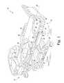
- FIG. 1is a perspective view of a patient support apparatus including an adjustable foot section
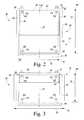
- FIG. 2is a top plan view of the foot section of FIG. 1 in one position
- FIG. 3is a top plan view of the foot section of FIG. 1 in another position
- FIG. 4is a top plan view of one embodiment of an adjustment mechanism of the foot section of FIG. 1 in the position corresponding to the one shown in FIG. 2 ;
- FIG. 5is a top plan view of the adjustment mechanism of FIG. 4 in the position corresponding to the one shown in FIG. 3 ;
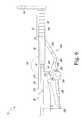
- FIG. 6is a diagrammatic representation of the patient support apparatus of FIG. 1 with the foot section in a raised position;
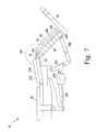
- FIG. 7is a diagrammatic representation similar to FIG. 6 with the surface of the foot section in an angled position.
- FIG. 8is a diagrammatic representation similar to FIG. 6 with the surface of the foot section in a lowered position.
- the chair bed 10includes a bed frame 12 having a head end 14 and a foot end 16 and an adjustable foot section 18 pivotably coupled to foot end 16 of the bed frame 12 .
- a longitudinal axis 20extends along the centerline of the bed frame 12 between the head end 14 and the foot end 16 .
- the bed frame 12has a base 22 , an intermediate frame 24 positioned above the base 22 , and a deck 26 positioned above the intermediate frame 24 .
- the bed frame 12includes a lift mechanism to raise and lower the intermediate frame 24 relative to the base 22 and a head articulation mechanism to raise and lower a head and/or upper torso section 28 of the deck 26 , and a foot articulation mechanism (see FIGS. 6-8 ) to raise and lower the adjustable foot section 18 .
- the chair bed 10is configured to assume a variety of positions, including a horizontal position, a chair-like position, Trendelenburg, reverse Trendelenburg, and/or other positions.
- the chair bed 10includes a controller 30 configured to control the operation of each of those articulation mechanisms based on the user input received via a user interface 32 .
- a mattress assembly 36is supported by the deck 26 of the bed frame 12 and a deck 38 of the adjustable foot section 18 .
- the mattress assembly 36includes a cover defining an interior region in which a variety of support components such as air bladders, foam, three-dimensional thermoplastic fibers, and/or other support elements may be arranged.
- air bladdersare configured to provide one or more therapeutic services to a person positioned on the mattress assembly 36 .
- the adjustable foot section 18is shown with the mattress assembly 36 removed.
- the adjustable foot section 18has a head end 40 , which is pivotably coupled to the foot end 16 of the bed frame 12 , and a foot end 42 having a foot board 44 secured thereto.
- the adjustable foot section 18also includes an adjustment mechanism 46 , and the deck 38 is positioned over the adjustment mechanism 46 .
- the deck 38 of the adjustable foot section 18includes a fixed deck section 50 and a sliding deck section 52 .
- the adjustment mechanism 46acts on the sliding deck section 52 to move the sliding deck section 52 relative to the foot end 16 of the bed frame 12 between the extended position shown in FIG. 2 and the retracted position shown in FIG. 3 .
- both deck sections 50 , 52may be configured to move relative to the foot end 16 of the bed frame 12 .
- the deck 38also includes a side deck section 54 and a side deck section 56 .
- the side deck section 54is pivotably coupled to a side panel 58 of the fixed deck section 50 via a hinge joint 60 .
- the side deck section 56is also pivotably coupled to another side panel 62 of the fixed deck section 50 via a hinge joint 64 .
- the side deck sections 54 , 56are configured to rotate relative to the fixed deck section 50 between the lowered positions shown in FIG. 2 and the raised positions shown in FIG. 3 .
- the adjustment mechanism 46acts on the side deck sections 54 , 56 to move those sections between their respective lowered and raised positions.
- each of the hinge joints 60 , 64is embodied as a single rotating hinge extending along the side panels 58 , 62 ; it will be appreciated that in other embodiments more than one hinge may be used for each hinge joint.
- the deck sections 50 , 52 , 54 , 56define a foot support surface 66 having a length dimension 68 extending along the longitudinal axis 20 and a width dimension 70 extending transverse to the longitudinal axis 20 .
- the length dimension 68extends a length 72 and the width dimension 70 extends a width 74 , as shown in FIG. 2 .
- the length dimension 68is decreased to a length 76 while the width dimension 70 is increased to a width 78 , as shown in FIG. 3 .
- the foot support surface 66becomes wider and shorter as the foot end 42 of the adjustable foot section 18 is moved toward the bed frame 12 and becomes narrower and longer as the foot end 42 of the adjustable foot section 18 is moved away from the bed frame 12 .
- the adjustment mechanism 46has a base frame 80 that includes a pair of telescopic arms 84 , 86 pivotably coupled to the intermediate frame 24 and a pair of support beam 88 , 90 extending therebetween.
- the telescopic arm 84includes a pair of arm sections 92 , 94 that are moveable relative to one another. Specifically, an end of arm section 94 is received into, and telescopes with, an end of the arm section 92 .
- the arm section 92 of the arm 84is coupled to a mounting arm 96 extending from the bed frame 12 at a pivot joint 98 .
- the pivot joint 98includes a cylindrical pivot pin 100 that extends through, and is received in, a hole 102 defined in the mounting arm 96 and a clevis 104 formed at an end 106 of arm section 92 .
- the telescopic arm 86also includes a pair of arm sections 108 , 110 that are moveable relative to one another. Specifically, an end of arm section 110 is received into, and telescopes with, an end of the arm section 108 .
- the arm section 108 of the arm 86is coupled to another mounting arm 112 extending from the bed frame 12 at a pivot joint 114 .
- the pivot joint 114like the pivot joint 98 , includes a cylindrical pivot pin 116 that is received by a hole 118 defined in the mounting arm 112 and a clevis 120 formed at an end 122 of arm section 108 .
- pivot joints 98 , 114may include any combination of holes, pins, rods, and other structures necessary to pivotably couple the arms 84 , 86 (and thus the adjustable foot section 18 ) to the bed frame 12 .
- the support beam 88which extends transverse to the longitudinal axis 20 of the bed frame 12 , is secured to the end 106 of the arm section 92 and the end 122 of the arm section 108 .
- the support beam 90which similarly extends transverse to the longitudinal axis 20 of the bed frame 12 , is secured to an end 124 of the arm section 94 and the end 126 of the arm section 110 . In that way, the support beam 88 , 90 join the pair of telescopic arms 84 , 86 , thereby forming the base frame 80 .
- the adjustment mechanism 46also includes a pair of cross links 130 , 132 arranged in a crisscross pattern 134 on the base frame 80 and an linear actuator 136 configured to move the adjustment mechanism 46 between the elongated position shown in FIG. 4 and the condensed position shown in FIG. 5 .
- the cross link 130includes a rod 140 extending from a link end 142 positioned adjacent to the end 106 of the arm section 92 to an opposite link end 144 .
- a rectangular slot 146is defined in the link end 142 of the cross link 130 and is sized to receive a pin 148 extending upwardly from the arm section 92 of the arm 84 .
- Another rectangular slot 150is defined in the link end 144 of the cross link 130 and is also sized to receive a pin 152 extending upwardly from the support beam 90 . As the adjustment mechanism 46 moves between the elongated position and the condensed position, the slots 146 , 150 slide and pivot relative the pins 148 , 152 .
- the cross link 132also includes a rod 154 extending from a link end 156 positioned adjacent to the end 122 of the arm section 108 to an opposite link end 158 .
- a rectangular slot 160is defined in the link end 156 of the cross link 132 and is sized to receive a pin 162 extending upwardly from the arm section 108 of the arm 86 .
- Another rectangular slot 164is defined in the link end 158 of the cross link 132 and is also sized to receive a pin 166 extending upwardly from the support beam 90 . As the adjustment mechanism 46 moves between the elongated position and the condensed position, the slots 160 , 164 slide and pivot relative to the pins 162 , 166 .
- the pins 148 , 162extend through openings defined in the fixed deck section 50 while the pins 152 , 166 extend through openings defined in the sliding deck section 52 .
- the pins 148 , 152 , 162 , 166are externally-threaded rods sized to receive corresponding internally-threaded nuts 168 , 170 , 172 , 174 . In that way, the pins 148 , 152 , 162 , 166 couple the deck 38 to the adjustment mechanism 46 . It will be appreciated that in other embodiments other fasteners may be used to couple the deck 38 to the adjustment mechanism 46 .
- the linear actuator 136includes a housing 180 having a rod 182 extending outwardly therefrom and an electric motor 184 coupled to the housing 180 .
- the housing 180has a pair of flanges 186 , 188 that are secured to the support beam 88 via a pair of fasteners 190 , 192 .
- the rod 182includes a piston 194 that extends from the housing 180 to an end 198 .
- the cross links 130 , 132are coupled to the end 198 of the piston 194 at a pivot joint 200 located at the intersection of the cross links 130 , 132 .
- the pivot joint 200is also positioned on the longitudinal axis 20 of the bed frame 12 .
- the pivot joint 200includes a cylindrical pivot pin 202 that extends through, and is positioned in, a pair of holes 204 defined in the cross links 130 , 132 , respectively, and a hole (not shown) defined in the end 198 .
- the electric motor 184is electrically coupled to the controller 30 of the chair bed 10 , and the controller 30 controls the operation of the motor 184 .
- the motor 184is configured to extend and retract the piston 194 relative to the housing 180 , thereby causing the adjustment mechanism 46 to move between the elongated position shown in FIG. 4 and the condensed position shown in FIG. 5 .
- the linear actuator 136may use servos, hydraulics, or pneumatics in place of, or in addition to, the electric motor 184 .
- the adjustment mechanism 46further includes a rotating link 210 extending between the support beam 90 and the cross link 130 .
- the rotating link 210is pivotably coupled to the support beam 90 at a pivot joint 212 positioned on the longitudinal axis 20 of the bed frame 12 and is pivotably coupled to the cross link 130 at a pivot joint 214 .
- the pivot joint 214is located at a point 218 equidistant from the link end 144 of the cross link 130 and the pivot joint 200 .
- Each of the pivot joints 212 , 214includes a cylindrical pivot pin 216 that extends through, and is positioned in, a pair of holes 220 defined in the cross link 130 and the support beam 90 , respectively.
- the adjustable foot section 18may be placed in any location between the elongated or extended position shown in FIGS. 2 and 4 and the condensed or retracted position shown in FIGS. 3 and 5 .
- a usermay access the user interface 32 and command the controller 30 to activate the electric motor 184 .
- the electric motor 184causes the piston 194 to retract into the housing 180 .
- the pivot joint 200is moved in the direction indicated by arrow 230 , and the cross links 130 , 132 rotate about the pivot joint 200 as the slots 146 , 150 , 160 , 164 defined in the cross links 130 , 132 slide and pivot about the pins 148 , 152 , 162 , 166 .
- the crisscross pattern 134 of the cross links 130 , 132has a dimension 232 extending along the longitudinal axis 20 that is decreased as the piston 194 is retracted.
- the change in the dimension 232results from the decreased distance between the link end 142 of the cross link 130 and the link end 158 of the cross link 132 , and the decreased distance between the link end 156 of the cross link 132 and the link end 144 of the cross link 130 .
- the link section 94 of the arm 84is drawn into the arm section 92 .
- the arm section 110 of the arm 86is drawn into the arm section 108 .
- the movement of the arm sections 92 , 94 and the arm sections 108 , 110causes the support beam 90 to move toward the foot end 16 of the bed frame 12 and thereby move the pins 152 , 166 extending upwardly from the support beam 90 toward the foot end 16 .
- the sliding deck section 52is coupled to the adjustable foot section 18 via the pins 152 , 166 , the movement of the pins 152 , 166 toward the foot end 16 of the bed frame 12 causes the sliding deck section 52 to move from the extended position to the retracted position. In that way, the length dimension 68 of the support surface 66 decreases from the length 72 shown in FIG. 2 to the length 76 shown in FIG. 3 .
- the crisscross pattern 134has another dimension 234 extending transverse to the longitudinal axis 20 that is increased as the piston 194 is retracted.
- the change in the dimension 234results from the increased distance between the link end 142 of the cross link 130 and the link end 156 of the cross link 132 , and the increased distance between the link end 144 of the cross link 130 and the link end 158 of the cross link 132 .
- the link ends 142 , 158 of the cross links 130 , 132move outward, the link ends 142 , 158 engage with the inner surface 236 (see FIG.
- the link ends 142 , 158support the side deck section 54 in the raised position.
- the link ends 144 , 156 of the cross links 130 , 132move outward, the link ends 144 , 158 engage with the inner surface (not shown) of the side deck section 56 and push on the side deck section 56 , thereby causing the side deck section 56 to rotate from the lowered position to the raised position.
- the link ends 144 , 156also support the side deck section 56 in the raised position.
- the width dimension 70is the width 78 shown in FIG. 3 .
- the foot section 18is shown in a number of positions relative to the chair bed 10 , and the adjustment mechanism 46 is positioned behind the side deck section 54 and an adjustable curtain 240 secured to underside of the deck 38 . Adjusting the length and width of the foot section 18 may be used to modify the length of the chair bed 10 to accommodate patients of different heights, or may be used to retract the foot section 18 when the foot section 18 is moved to a generally vertical position as shown in FIG. 8 . As shown in FIGS. 6-8 , the chair bed 10 includes a foot articulation mechanism 242 that pivots the foot section 18 relative to the intermediate frame 24 .
- the mechanism 242includes a linear actuator 250 having a rod 252 pivotably coupled to a crank 254 at a rod end 256 and the intermediate frame 24 at a rod end 258 .
- the crank 254includes an end 260 pivotably coupled to the intermediate frame 24 and an end 264 pivotably coupled to a support arm 266 .
- the crank 254supports the foot section 18 through the support arm 266 , which is pivotally coupled to the arm 84 of the foot section 18 .
- the rod 252which extends and retracts relative to a body 268 of the actuator 250 , acts on the crank 254 , thereby causing the crank to rotate about an axis 270 .
- Operation of the linear actuator 250causes the foot section 18 to move relative to a seat deck section 272 of the deck 26 such that a support surface 274 of the seat deck section 272 and the support surface 66 of the foot section 18 form a variable angle ⁇ .
- the angle ⁇is variable between the obtuse angle shown in FIG. 7 and the reflex angle shown in FIG. 8 , with a straight angle being formed between the support surfaces 66 , 274 when the foot section 18 is positioned to support a patient in a supine position on the chair bed 10 , as shown in FIG. 6 .
- the angle ⁇may be as great as approximately 270° when the foot section 18 is lowered to position the chair bed 10 in the chair egress position.
- the foot section 18In the chair egress position shown in FIG. 8 , the foot section 18 is fully condensed to reduce the height necessary to separate the foot section 18 from the floor 280 .
- the support surface 66is also wider when in the chair egress position shown in FIG. 8 , thereby providing the patient with additional support while getting into and out of the chair bed 10 .
- actuator 136 of the adjustment mechanism 40is shown connected to the pair of cross links 130 , 132 , in other embodiments the actuator 136 may be connected to only one of the cross links. In such embodiments, the actuator 136 may be connected to an end of the cross link.
- each of the telescopic arms 84 , 86may be replaced by one or more linear actuators that would provide the motive force necessary to move the foot section 18 . In such embodiments, the actuator 136 may be eliminated.
- the side deck sections 54 , 56are shown hinged to the fixed deck section 50 , the side deck sections 54 , 56 may instead be configured to slide relative to the fixed deck section 50 between extended and retracted positions.
- the cross links 130 , 132 and the deck sections 54 , 56may include any pins, slots, or other structures necessary to permit the cross links 130 , 132 to act on the deck sections 54 , 56 .
Landscapes
- Health & Medical Sciences (AREA)
- Nursing (AREA)
- Life Sciences & Earth Sciences (AREA)
- Animal Behavior & Ethology (AREA)
- General Health & Medical Sciences (AREA)
- Public Health (AREA)
- Veterinary Medicine (AREA)
- Invalid Beds And Related Equipment (AREA)
- Accommodation For Nursing Or Treatment Tables (AREA)
Abstract
Description
Claims (19)
Priority Applications (1)
| Application Number | Priority Date | Filing Date | Title |
|---|---|---|---|
| US13/021,370US8474076B2 (en) | 2011-02-04 | 2011-02-04 | Adjustable foot section for a patient support apparatus |
Applications Claiming Priority (1)
| Application Number | Priority Date | Filing Date | Title |
|---|---|---|---|
| US13/021,370US8474076B2 (en) | 2011-02-04 | 2011-02-04 | Adjustable foot section for a patient support apparatus |
Publications (2)
| Publication Number | Publication Date |
|---|---|
| US20120198629A1 US20120198629A1 (en) | 2012-08-09 |
| US8474076B2true US8474076B2 (en) | 2013-07-02 |
Family
ID=46599640
Family Applications (1)
| Application Number | Title | Priority Date | Filing Date |
|---|---|---|---|
| US13/021,370Active2031-07-21US8474076B2 (en) | 2011-02-04 | 2011-02-04 | Adjustable foot section for a patient support apparatus |
Country Status (1)
| Country | Link |
|---|---|
| US (1) | US8474076B2 (en) |
Cited By (17)
| Publication number | Priority date | Publication date | Assignee | Title |
|---|---|---|---|---|
| US9539155B2 (en) | 2012-10-26 | 2017-01-10 | Hill-Rom Services, Inc. | Control system for patient support apparatus |
| US9951904B2 (en) | 2015-03-24 | 2018-04-24 | Stryker Corporation | Rotatable seat clamps for rail clamp |
| US10130536B2 (en) | 2013-09-06 | 2018-11-20 | Stryker Corporation | Patient support usable with bariatric patients |
| US10188569B2 (en) | 2013-09-06 | 2019-01-29 | Stryker Corporation | Patient support usable with bariatric patients |
| US10322044B2 (en) | 2013-03-15 | 2019-06-18 | Stryker Corporation | Medical support apparatus |
| US10426680B2 (en) | 2015-07-31 | 2019-10-01 | Hill-Rom Services, Inc. | Air bladder control of mattress/frame width expansion |
| US10463556B2 (en) | 2017-07-13 | 2019-11-05 | Stryker Corporation | Patient mobility system with integrated ambulation device |
| US10478364B2 (en) | 2014-03-10 | 2019-11-19 | Stryker Corporation | Limb positioning system |
| US10660809B2 (en) | 2015-09-11 | 2020-05-26 | Stryker Corporation | Telescoping assembly for use on a patient support apparatus |
| US20200346571A1 (en)* | 2019-05-01 | 2020-11-05 | Ford Global Technologies, Llc | Leg support system for seating assembly |
| US10835430B2 (en) | 2016-09-02 | 2020-11-17 | Stryker Corporation | Patient mobility system with integrated ambulation device |
| US10842701B2 (en) | 2016-10-14 | 2020-11-24 | Stryker Corporation | Patient support apparatus with stabilization |
| US10869792B2 (en) | 2016-09-02 | 2020-12-22 | Stryker Corporation | Patient support apparatus |
| US11304864B2 (en) | 2016-09-02 | 2022-04-19 | Stryker Corporation | Patient support systems with a chair configuration and a stowable foot section |
| US11484450B2 (en) | 2018-10-08 | 2022-11-01 | Stryker Corporation | Patient support apparatus having bearing arrangement for deck extension assembly |
| US20230157911A1 (en)* | 2021-10-14 | 2023-05-25 | Leslie Dale Foster | Hospital bed with foot egress |
| US20240024179A1 (en)* | 2021-10-14 | 2024-01-25 | Safe Harbor Hospital Beds, Llc | Hospital bed with foot egress |
Families Citing this family (3)
| Publication number | Priority date | Publication date | Assignee | Title |
|---|---|---|---|---|
| WO2009158018A1 (en) | 2008-06-27 | 2009-12-30 | Kreg Medical, Inc. | Bed with modified foot deck |
| US10179077B2 (en) | 2014-04-18 | 2019-01-15 | Kreg Medical, Inc. | Patient support with stand-up and sit features |
| CN111904752B (en)* | 2020-09-15 | 2021-05-07 | 姜永杰 | Nursing is raised device with low limbs |
Citations (78)
| Publication number | Priority date | Publication date | Assignee | Title |
|---|---|---|---|---|
| US262365A (en)* | 1882-08-08 | Spring mattress or bed-bottom | ||
| US286166A (en)* | 1883-10-09 | Petefts | ||
| US3003158A (en)* | 1959-05-13 | 1961-10-10 | Burton Dixie Corp | Adjustable bed frame |
| US3220022A (en) | 1963-12-23 | 1965-11-30 | Nelson Ted | Hospital bed sliding foot section |
| US3220021A (en)* | 1964-04-09 | 1965-11-30 | Nelson Ted | Adjustable seat length hospital bed |
| US3413663A (en) | 1967-02-23 | 1968-12-03 | David T. Swann | Combination stretcher, table, chair combination |
| US3744066A (en)* | 1971-08-18 | 1973-07-10 | V Falivene | Selected width bed frame |
| US3893197A (en) | 1974-02-11 | 1975-07-08 | Maurine E Ricke | Hospital bed footboard assembly |
| US4183015A (en) | 1978-06-26 | 1980-01-08 | Hill-Rom Company, Inc. | Side guard for bed including means for controlling remote electrical devices |
| US4409695A (en) | 1981-02-03 | 1983-10-18 | Burke, Inc. | Adjustable bed for morbidly obese patients |
| US4615058A (en)* | 1985-01-28 | 1986-10-07 | Landstingens Inkopscentral Lic, Ekonomisk Forening | Delivery bed |
| US4669136A (en) | 1985-04-02 | 1987-06-02 | Med-Con Of Georgia, Inc. | Combination hospital bed and surgical table |
| US4680790A (en) | 1985-08-22 | 1987-07-14 | Joerns Healthcare, Inc. | Bedside control module for healthcare stations and the like |
| US4700417A (en) | 1986-07-16 | 1987-10-20 | Mcgovern Lorayne | Gurney extension |
| US4803744A (en) | 1987-05-19 | 1989-02-14 | Hill-Rom Company, Inc. | Inflatable bed |
| US4805249A (en) | 1986-09-19 | 1989-02-21 | Pulukadang Freddy Usman | Rehabilitation bed |
| US4847929A (en) | 1986-12-02 | 1989-07-18 | Milenko Pupovic | Bed with adjustable positions |
| US4862529A (en) | 1988-07-13 | 1989-09-05 | Hill-Rom Company, Inc. | Hospital bed convertible to chair |
| US4894876A (en)* | 1988-07-15 | 1990-01-23 | Hill-Rom Company, Inc. | Multipurpose maternity care bed |
| US4928332A (en)* | 1988-11-07 | 1990-05-29 | Ralph Ogden | Adjustable mattress foundation for beds |
| US4968013A (en)* | 1989-11-22 | 1990-11-06 | Midmark Corporation | Footrest glide assembly |
| US4985946A (en) | 1989-07-28 | 1991-01-22 | Hill-Rom Company, Inc. | Hospital bed adapted for use with a C-arm |
| US5023967A (en) | 1988-03-23 | 1991-06-18 | American Life Support Technology | Patient support system |
| US5077843A (en) | 1990-07-28 | 1992-01-07 | Hill-Rom Company, Inc. | Hospital bed and assemblies of hospital care apparatus |
| US5083332A (en) | 1989-07-28 | 1992-01-28 | Hill-Rom Company, Inc. | Hospital bed with collapsible side edges and laterally-movable side guards |
| US5179744A (en) | 1989-07-28 | 1993-01-19 | Hill-Rom Company, Inc. | Hospital bed with inflatable and collapsible side edges and laterally-movable side guards |
| US5377370A (en) | 1993-06-10 | 1995-01-03 | Hill-Rom Company, Inc. | Hospital bed with collapsing wing |
| US5398357A (en) | 1993-06-03 | 1995-03-21 | Hill-Rom Company, Inc. | Hospital bed convertible to chair configuration |
| US5454126A (en) | 1994-01-25 | 1995-10-03 | Hill-Rom Company, Inc. | Foot egress chair bed |
| US5479666A (en) | 1994-01-25 | 1996-01-02 | Hill-Rom Company, Inc. | Foot egress chair bed |
| US5542136A (en) | 1994-08-05 | 1996-08-06 | Stryker Corporation | Portable mattress for treating decubitus ulcers |
| US5542138A (en) | 1995-02-06 | 1996-08-06 | Williams; Terry N. | Bedside control unit for a hospital bed |
| US5592153A (en) | 1993-11-30 | 1997-01-07 | Hill-Rom Company, Inc. | Hospital bed communication and control device |
| US5613255A (en)* | 1994-12-27 | 1997-03-25 | Hill-Rom, Inc. | Hospital bed having scissors lifting apparatus |
| US5628078A (en) | 1994-08-15 | 1997-05-13 | Midmark Corporation | Surgical table side extender assembly |
| US5630238A (en) | 1995-08-04 | 1997-05-20 | Hill-Rom, Inc. | Bed with a plurality of air therapy devices, having control modules and an electrical communication network |
| GB2313303A (en) | 1996-05-20 | 1997-11-26 | Egerton Hospital Equip | Bed frame with expandable end section to increase length |
| US5715548A (en) | 1994-01-25 | 1998-02-10 | Hill-Rom, Inc. | Chair bed |
| US5745936A (en) | 1995-01-19 | 1998-05-05 | Windryder Engineering, Inc. | Safety bed with dual purpose side panels |
| US5771511A (en) | 1995-08-04 | 1998-06-30 | Hill-Rom, Inc. | Communication network for a hospital bed |
| US5878452A (en) | 1996-12-03 | 1999-03-09 | Hill-Rom, Inc. | Long term care bed controls |
| WO1999015126A2 (en) | 1997-09-23 | 1999-04-01 | Hill-Rom, Inc. | Hospital bed having a retracting foot section |
| US6008598A (en) | 1998-04-22 | 1999-12-28 | Patmark Company, Inc. | Hand-held controller for bed and mattress assembly |
| US6089593A (en) | 1997-02-10 | 2000-07-18 | Hill-Rom, Inc. | Ambulatory care chair |
| EP1020146A1 (en) | 1998-07-31 | 2000-07-19 | France Bed Company, Limited | Mattress device and bed device |
| US6131868A (en) | 1992-11-30 | 2000-10-17 | Hill-Rom, Inc. | Hospital bed communication and control device |
| US6154899A (en) | 1998-10-19 | 2000-12-05 | Hill-Rom, Inc. | Resident transfer chair |
| US6182310B1 (en) | 1995-08-04 | 2001-02-06 | Hill-Rom, Inc. | Bed side rails |
| US6226816B1 (en) | 1996-10-23 | 2001-05-08 | Hill-Rom, Inc. | Procedural stretcher recline controls |
| US20010004777A1 (en)* | 1999-04-28 | 2001-06-28 | Hernandez Carlos J. | Mattress support and method |
| US6320510B2 (en) | 1999-03-05 | 2001-11-20 | Douglas J. Menkedick | Bed control apparatus |
| US20010044971A1 (en) | 2000-02-07 | 2001-11-29 | Borders Richard L. | Bariatric surface for an operating room table |
| US6357065B1 (en)* | 1999-11-15 | 2002-03-19 | Mellen Air Manufacturing, Inc. | Variable width bariatric modularbed |
| US6362725B1 (en) | 1993-07-12 | 2002-03-26 | Hill-Rom Services, Inc. | Bed status information system for hospital beds |
| US6486792B1 (en) | 1998-04-14 | 2002-11-26 | Hill-Rom Services, Inc. | Communication and bed function control apparatus |
| US6526609B2 (en) | 2001-03-29 | 2003-03-04 | William Beaumont Hospital | X-ray transparent hospital bed compatible with open geometry portable CT scanners |
| EP1296580A1 (en) | 2000-04-12 | 2003-04-02 | Franklin Eugene Elliott | System for producing anthropometric, adjustable, articulated beds |
| US6611979B2 (en) | 1997-09-23 | 2003-09-02 | Hill-Rom Services, Inc. | Mattress having a retractable foot section |
| US6726279B1 (en)* | 1997-02-10 | 2004-04-27 | Hill-Rom Services, Inc. | Hydraulic controls for ambulatory care chair |
| US20050081295A1 (en)* | 2003-10-20 | 2005-04-21 | Malcolm Roger J. | Surgical table width extension and angularly orientable attachment |
| US20050102755A1 (en)* | 2003-09-29 | 2005-05-19 | The Brewer Company, Llc | Leg rest and kneeler assembly for a medical examination table |
| US20060021142A1 (en)* | 2004-07-30 | 2006-02-02 | Hornbach David W | Patient support having powered adjustable width |
| US20060026762A1 (en)* | 2004-07-28 | 2006-02-09 | Hornbach David M | Hospital bed |
| US7007323B2 (en)* | 2000-03-24 | 2006-03-07 | Hill-Rom Services, Inc. | Bed siderails having flexible portions |
| US20060195984A1 (en) | 2005-03-07 | 2006-09-07 | Reza Hakamiun | Siderail for a hospital bed |
| US20070061971A1 (en)* | 2005-07-28 | 2007-03-22 | The Brewer Company, Llc | Medical examination table |
| US7260860B2 (en) | 2004-08-04 | 2007-08-28 | Hill-Rom Services, Inc. | Mattress system for a hospital bed |
| US20080040857A1 (en) | 2004-07-02 | 2008-02-21 | Karmer Duwayne E Jr | Bariatric transport with improved maneuverability |
| US7458119B2 (en) | 2004-07-30 | 2008-12-02 | Hill-Rom Services, Inc. | Bed having a chair egress position |
| US7464425B2 (en) | 2004-08-04 | 2008-12-16 | Hill-Rom Services, Inc. | Hospital bed |
| US7520006B2 (en) | 2002-09-06 | 2009-04-21 | Hill-Rom Services, Inc. | Hospital bed including moveable foot portion |
| US7568247B2 (en) | 2002-12-26 | 2009-08-04 | Gendron, Inc. | Bariatric patient management system |
| US7600817B2 (en) | 2004-08-16 | 2009-10-13 | Hill-Rom Services, Inc. | Chair |
| US7743441B2 (en) | 2004-09-13 | 2010-06-29 | Kreg Therapeutics, Inc. | Expandable width bed |
| US7788748B2 (en) | 2005-04-06 | 2010-09-07 | Piedmont Global Solutions, Inc. | Hospital beds with a rotating sleep surface that can translate into a chair configuration |
| US8104122B2 (en)* | 2005-12-19 | 2012-01-31 | Hill-Rom Services, Inc. | Patient support having an extendable foot section |
| US8177296B2 (en)* | 2009-08-25 | 2012-05-15 | Ruoey Lung Enterprise Corp. | Motorized rocking chair moved in a pendulum manner |
| US20120198628A1 (en)* | 2011-02-03 | 2012-08-09 | Richards Sandy M | Manually removable foot section |
- 2011
- 2011-02-04USUS13/021,370patent/US8474076B2/enactiveActive
Patent Citations (113)
| Publication number | Priority date | Publication date | Assignee | Title |
|---|---|---|---|---|
| US262365A (en)* | 1882-08-08 | Spring mattress or bed-bottom | ||
| US286166A (en)* | 1883-10-09 | Petefts | ||
| US3003158A (en)* | 1959-05-13 | 1961-10-10 | Burton Dixie Corp | Adjustable bed frame |
| US3220022A (en) | 1963-12-23 | 1965-11-30 | Nelson Ted | Hospital bed sliding foot section |
| US3220021A (en)* | 1964-04-09 | 1965-11-30 | Nelson Ted | Adjustable seat length hospital bed |
| US3413663A (en) | 1967-02-23 | 1968-12-03 | David T. Swann | Combination stretcher, table, chair combination |
| US3744066A (en)* | 1971-08-18 | 1973-07-10 | V Falivene | Selected width bed frame |
| US3893197A (en) | 1974-02-11 | 1975-07-08 | Maurine E Ricke | Hospital bed footboard assembly |
| US4183015A (en) | 1978-06-26 | 1980-01-08 | Hill-Rom Company, Inc. | Side guard for bed including means for controlling remote electrical devices |
| US4409695A (en) | 1981-02-03 | 1983-10-18 | Burke, Inc. | Adjustable bed for morbidly obese patients |
| US4615058A (en)* | 1985-01-28 | 1986-10-07 | Landstingens Inkopscentral Lic, Ekonomisk Forening | Delivery bed |
| US4669136A (en) | 1985-04-02 | 1987-06-02 | Med-Con Of Georgia, Inc. | Combination hospital bed and surgical table |
| US4680790A (en) | 1985-08-22 | 1987-07-14 | Joerns Healthcare, Inc. | Bedside control module for healthcare stations and the like |
| US4700417A (en) | 1986-07-16 | 1987-10-20 | Mcgovern Lorayne | Gurney extension |
| US4805249A (en) | 1986-09-19 | 1989-02-21 | Pulukadang Freddy Usman | Rehabilitation bed |
| US4847929A (en) | 1986-12-02 | 1989-07-18 | Milenko Pupovic | Bed with adjustable positions |
| US4803744A (en) | 1987-05-19 | 1989-02-14 | Hill-Rom Company, Inc. | Inflatable bed |
| US5023967A (en) | 1988-03-23 | 1991-06-18 | American Life Support Technology | Patient support system |
| US5345629A (en) | 1988-03-23 | 1994-09-13 | American Life Support Technology | Patient support system |
| US4862529A (en) | 1988-07-13 | 1989-09-05 | Hill-Rom Company, Inc. | Hospital bed convertible to chair |
| US4894876A (en)* | 1988-07-15 | 1990-01-23 | Hill-Rom Company, Inc. | Multipurpose maternity care bed |
| US4928332A (en)* | 1988-11-07 | 1990-05-29 | Ralph Ogden | Adjustable mattress foundation for beds |
| US4985946A (en) | 1989-07-28 | 1991-01-22 | Hill-Rom Company, Inc. | Hospital bed adapted for use with a C-arm |
| US5083332A (en) | 1989-07-28 | 1992-01-28 | Hill-Rom Company, Inc. | Hospital bed with collapsible side edges and laterally-movable side guards |
| US5179744A (en) | 1989-07-28 | 1993-01-19 | Hill-Rom Company, Inc. | Hospital bed with inflatable and collapsible side edges and laterally-movable side guards |
| US4968013A (en)* | 1989-11-22 | 1990-11-06 | Midmark Corporation | Footrest glide assembly |
| US5077843A (en) | 1990-07-28 | 1992-01-07 | Hill-Rom Company, Inc. | Hospital bed and assemblies of hospital care apparatus |
| US6131868A (en) | 1992-11-30 | 2000-10-17 | Hill-Rom, Inc. | Hospital bed communication and control device |
| US5398357A (en) | 1993-06-03 | 1995-03-21 | Hill-Rom Company, Inc. | Hospital bed convertible to chair configuration |
| US5377370A (en) | 1993-06-10 | 1995-01-03 | Hill-Rom Company, Inc. | Hospital bed with collapsing wing |
| US6362725B1 (en) | 1993-07-12 | 2002-03-26 | Hill-Rom Services, Inc. | Bed status information system for hospital beds |
| US5592153A (en) | 1993-11-30 | 1997-01-07 | Hill-Rom Company, Inc. | Hospital bed communication and control device |
| US5479666A (en) | 1994-01-25 | 1996-01-02 | Hill-Rom Company, Inc. | Foot egress chair bed |
| US6336235B1 (en) | 1994-01-25 | 2002-01-08 | Hill-Rom Services, Inc. | Chair bed |
| US6163903A (en) | 1994-01-25 | 2000-12-26 | Hill-Rom Inc. | Chair bed |
| US5715548A (en) | 1994-01-25 | 1998-02-10 | Hill-Rom, Inc. | Chair bed |
| US5454126A (en) | 1994-01-25 | 1995-10-03 | Hill-Rom Company, Inc. | Foot egress chair bed |
| US5542136A (en) | 1994-08-05 | 1996-08-06 | Stryker Corporation | Portable mattress for treating decubitus ulcers |
| US5628078A (en) | 1994-08-15 | 1997-05-13 | Midmark Corporation | Surgical table side extender assembly |
| US5613255A (en)* | 1994-12-27 | 1997-03-25 | Hill-Rom, Inc. | Hospital bed having scissors lifting apparatus |
| US7523515B2 (en) | 1995-01-03 | 2009-04-28 | Hill-Rom Services, Inc. | Hospital bed and mattress having a retractable foot section |
| US6496993B2 (en) | 1995-01-03 | 2002-12-24 | Hill-Rom Services, Inc. | Hospital bed and mattress having a retracting foot section |
| US7216384B2 (en) | 1995-01-03 | 2007-05-15 | Hill-Rom Services, Inc. | Hospital bed and mattress having a retractable foot section |
| US7000272B2 (en) | 1995-01-03 | 2006-02-21 | Hill-Rom Services, Inc. | Hospital bed and mattress having a retractable foot section |
| US6684427B2 (en) | 1995-01-03 | 2004-02-03 | Hill-Rom Services, Inc. | Hospital bed and matress having a retractable foot section |
| US20030088920A1 (en)* | 1995-01-03 | 2003-05-15 | Allen E. David | Hospital bed and mattress having a retractable foot section |
| US6212714B1 (en) | 1995-01-03 | 2001-04-10 | Hill-Rom, Inc. | Hospital bed and mattress having a retracting foot section |
| US5745936A (en) | 1995-01-19 | 1998-05-05 | Windryder Engineering, Inc. | Safety bed with dual purpose side panels |
| US5542138A (en) | 1995-02-06 | 1996-08-06 | Williams; Terry N. | Bedside control unit for a hospital bed |
| US6182310B1 (en) | 1995-08-04 | 2001-02-06 | Hill-Rom, Inc. | Bed side rails |
| US5630238A (en) | 1995-08-04 | 1997-05-20 | Hill-Rom, Inc. | Bed with a plurality of air therapy devices, having control modules and an electrical communication network |
| US6279183B1 (en) | 1995-08-04 | 2001-08-28 | Hill-Rom, Inc. | Communication network for a hospital bed |
| US5771511A (en) | 1995-08-04 | 1998-06-30 | Hill-Rom, Inc. | Communication network for a hospital bed |
| GB2313303A (en) | 1996-05-20 | 1997-11-26 | Egerton Hospital Equip | Bed frame with expandable end section to increase length |
| US6226816B1 (en) | 1996-10-23 | 2001-05-08 | Hill-Rom, Inc. | Procedural stretcher recline controls |
| US6185767B1 (en) | 1996-12-03 | 2001-02-13 | Hill-Rom, Inc. | Controls for a bed |
| US5878452A (en) | 1996-12-03 | 1999-03-09 | Hill-Rom, Inc. | Long term care bed controls |
| US6315319B1 (en) | 1997-02-10 | 2001-11-13 | Hill-Rom Services, Inc. | Ambulatory care chair |
| US6565112B2 (en) | 1997-02-10 | 2003-05-20 | Hill-Rom Services, Inc. | Ambulatory care chair |
| US6846042B2 (en) | 1997-02-10 | 2005-01-25 | Hill-Rom Services, Inc. | Ambulatory care chair |
| US6726279B1 (en)* | 1997-02-10 | 2004-04-27 | Hill-Rom Services, Inc. | Hydraulic controls for ambulatory care chair |
| US6089593A (en) | 1997-02-10 | 2000-07-18 | Hill-Rom, Inc. | Ambulatory care chair |
| WO1999015126A2 (en) | 1997-09-23 | 1999-04-01 | Hill-Rom, Inc. | Hospital bed having a retracting foot section |
| US6611979B2 (en) | 1997-09-23 | 2003-09-02 | Hill-Rom Services, Inc. | Mattress having a retractable foot section |
| US6486792B1 (en) | 1998-04-14 | 2002-11-26 | Hill-Rom Services, Inc. | Communication and bed function control apparatus |
| US6396224B1 (en) | 1998-04-22 | 2002-05-28 | Hill-Rom Services, Inc. | Hand-held controller for bed and mattress assembly |
| US6008598A (en) | 1998-04-22 | 1999-12-28 | Patmark Company, Inc. | Hand-held controller for bed and mattress assembly |
| EP1020146A1 (en) | 1998-07-31 | 2000-07-19 | France Bed Company, Limited | Mattress device and bed device |
| US6324709B1 (en) | 1998-07-31 | 2001-12-04 | France Bed Co., Ltd. | Mattress apparatus and bed apparatus |
| US6185769B1 (en) | 1998-10-19 | 2001-02-13 | Hill-Rom, Inc. | Resident transfer chair |
| US6154899A (en) | 1998-10-19 | 2000-12-05 | Hill-Rom, Inc. | Resident transfer chair |
| US6320510B2 (en) | 1999-03-05 | 2001-11-20 | Douglas J. Menkedick | Bed control apparatus |
| US20020059678A1 (en)* | 1999-04-28 | 2002-05-23 | United Finishers, Inc. | Mattress support and method |
| US6477726B2 (en)* | 1999-04-28 | 2002-11-12 | Carlos J. Hernandez | Mattress support and method |
| US20010004777A1 (en)* | 1999-04-28 | 2001-06-28 | Hernandez Carlos J. | Mattress support and method |
| US6357065B1 (en)* | 1999-11-15 | 2002-03-19 | Mellen Air Manufacturing, Inc. | Variable width bariatric modularbed |
| US6658680B2 (en) | 1999-12-29 | 2003-12-09 | Hill-Rom Services, Inc. | Hospital bed |
| US6880189B2 (en) | 1999-12-29 | 2005-04-19 | Hill-Rom Services, Inc. | Patient support |
| US20010044971A1 (en) | 2000-02-07 | 2001-11-29 | Borders Richard L. | Bariatric surface for an operating room table |
| US6678908B2 (en) | 2000-02-07 | 2004-01-20 | Hill-Rom Services, Inc. | Bariatric surface for an operating room table |
| US7007323B2 (en)* | 2000-03-24 | 2006-03-07 | Hill-Rom Services, Inc. | Bed siderails having flexible portions |
| EP1296580A1 (en) | 2000-04-12 | 2003-04-02 | Franklin Eugene Elliott | System for producing anthropometric, adjustable, articulated beds |
| US6675415B2 (en) | 2001-03-29 | 2004-01-13 | William Beaumont Hospital | X-ray transparent hospital bed compatible with open geometry portable CT scanners |
| US6526609B2 (en) | 2001-03-29 | 2003-03-04 | William Beaumont Hospital | X-ray transparent hospital bed compatible with open geometry portable CT scanners |
| US7520006B2 (en) | 2002-09-06 | 2009-04-21 | Hill-Rom Services, Inc. | Hospital bed including moveable foot portion |
| US7669263B2 (en) | 2002-09-06 | 2010-03-02 | Hill-Rom Services, Inc. | Mattress assembly including adjustable length foot |
| US7568247B2 (en) | 2002-12-26 | 2009-08-04 | Gendron, Inc. | Bariatric patient management system |
| US20050102755A1 (en)* | 2003-09-29 | 2005-05-19 | The Brewer Company, Llc | Leg rest and kneeler assembly for a medical examination table |
| US20050081295A1 (en)* | 2003-10-20 | 2005-04-21 | Malcolm Roger J. | Surgical table width extension and angularly orientable attachment |
| US7210180B2 (en) | 2003-10-20 | 2007-05-01 | Malcolm Roger J | Surgical table width extension and angularly orientable attachment |
| US20080040857A1 (en) | 2004-07-02 | 2008-02-21 | Karmer Duwayne E Jr | Bariatric transport with improved maneuverability |
| US20060026762A1 (en)* | 2004-07-28 | 2006-02-09 | Hornbach David M | Hospital bed |
| US7730562B2 (en)* | 2004-07-30 | 2010-06-08 | Hill-Rom Services, Inc. | Patient support having powered adjustable width |
| US7406729B2 (en)* | 2004-07-30 | 2008-08-05 | Hill-Rom Services, Inc. | Patient support having powered adjustable width |
| US20080282472A1 (en)* | 2004-07-30 | 2008-11-20 | Hornbach David W | Patient support having powered adjustable width |
| US7458119B2 (en) | 2004-07-30 | 2008-12-02 | Hill-Rom Services, Inc. | Bed having a chair egress position |
| US20060021142A1 (en)* | 2004-07-30 | 2006-02-02 | Hornbach David W | Patient support having powered adjustable width |
| US7464425B2 (en) | 2004-08-04 | 2008-12-16 | Hill-Rom Services, Inc. | Hospital bed |
| US7832039B2 (en) | 2004-08-04 | 2010-11-16 | Hill-Rom Services, Inc. | Support surface with inflatable core zones |
| US7363663B2 (en) | 2004-08-04 | 2008-04-29 | Hill-Rom Services, Inc. | Mattress with automatic width adjustment |
| US7565710B2 (en) | 2004-08-04 | 2009-07-28 | Hill-Rom Services, Inc. | Support surface with inflatable width adjustment portion |
| US7260860B2 (en) | 2004-08-04 | 2007-08-28 | Hill-Rom Services, Inc. | Mattress system for a hospital bed |
| US7845032B2 (en) | 2004-08-04 | 2010-12-07 | Hill-Rom Services, Inc. | Hospital bed |
| US7461425B2 (en) | 2004-08-04 | 2008-12-09 | Hill-Rom Services, Inc. | Bed with automatically identifiable mattress type |
| US7600817B2 (en) | 2004-08-16 | 2009-10-13 | Hill-Rom Services, Inc. | Chair |
| US7743441B2 (en) | 2004-09-13 | 2010-06-29 | Kreg Therapeutics, Inc. | Expandable width bed |
| US20060195984A1 (en) | 2005-03-07 | 2006-09-07 | Reza Hakamiun | Siderail for a hospital bed |
| US7805782B2 (en) | 2005-03-07 | 2010-10-05 | Hill-Rom Services, Inc. | Siderail for a hospital bed |
| US7788748B2 (en) | 2005-04-06 | 2010-09-07 | Piedmont Global Solutions, Inc. | Hospital beds with a rotating sleep surface that can translate into a chair configuration |
| US20070061971A1 (en)* | 2005-07-28 | 2007-03-22 | The Brewer Company, Llc | Medical examination table |
| US8104122B2 (en)* | 2005-12-19 | 2012-01-31 | Hill-Rom Services, Inc. | Patient support having an extendable foot section |
| US8177296B2 (en)* | 2009-08-25 | 2012-05-15 | Ruoey Lung Enterprise Corp. | Motorized rocking chair moved in a pendulum manner |
| US20120198628A1 (en)* | 2011-02-03 | 2012-08-09 | Richards Sandy M | Manually removable foot section |
Cited By (34)
| Publication number | Priority date | Publication date | Assignee | Title |
|---|---|---|---|---|
| US10512573B2 (en) | 2012-10-26 | 2019-12-24 | Hill-Rom Services, Inc. | Control system for patient support apparatus |
| US9539155B2 (en) | 2012-10-26 | 2017-01-10 | Hill-Rom Services, Inc. | Control system for patient support apparatus |
| US11559448B2 (en) | 2013-03-15 | 2023-01-24 | Stryker Corporation | Medical support apparatus |
| US10322044B2 (en) | 2013-03-15 | 2019-06-18 | Stryker Corporation | Medical support apparatus |
| US10188569B2 (en) | 2013-09-06 | 2019-01-29 | Stryker Corporation | Patient support usable with bariatric patients |
| US11980580B2 (en) | 2013-09-06 | 2024-05-14 | Stryker Corporation | Patient support usable with bariatric patients |
| US11865056B2 (en) | 2013-09-06 | 2024-01-09 | Stryker Corporation | Patient support usable with bariatric patients |
| US10130536B2 (en) | 2013-09-06 | 2018-11-20 | Stryker Corporation | Patient support usable with bariatric patients |
| US10842694B2 (en) | 2013-09-06 | 2020-11-24 | Stryker Corporation | Patient support usable with bariatric patients |
| US11285061B2 (en) | 2013-09-06 | 2022-03-29 | Stryker Corporation | Patient support usable with bariatric patients |
| US10716722B2 (en) | 2013-09-06 | 2020-07-21 | Stryker Corporation | Patient support usable with bariatric patients |
| US11419776B2 (en) | 2013-09-06 | 2022-08-23 | Stryker Corporation | Patient support usable with bariatric patients |
| US10478364B2 (en) | 2014-03-10 | 2019-11-19 | Stryker Corporation | Limb positioning system |
| US9951904B2 (en) | 2015-03-24 | 2018-04-24 | Stryker Corporation | Rotatable seat clamps for rail clamp |
| US10426680B2 (en) | 2015-07-31 | 2019-10-01 | Hill-Rom Services, Inc. | Air bladder control of mattress/frame width expansion |
| US10660809B2 (en) | 2015-09-11 | 2020-05-26 | Stryker Corporation | Telescoping assembly for use on a patient support apparatus |
| US12336944B2 (en) | 2015-09-11 | 2025-06-24 | Stryker Corporation | Patient support apparatus having an extension |
| US11540963B2 (en) | 2015-09-11 | 2023-01-03 | Stryker Corporation | Patient support apparatus having an extension |
| US11554064B2 (en) | 2015-09-11 | 2023-01-17 | Stryker Corporation | Patient support apparatus having a telescoping assembly |
| US10835430B2 (en) | 2016-09-02 | 2020-11-17 | Stryker Corporation | Patient mobility system with integrated ambulation device |
| US11304864B2 (en) | 2016-09-02 | 2022-04-19 | Stryker Corporation | Patient support systems with a chair configuration and a stowable foot section |
| US10869792B2 (en) | 2016-09-02 | 2020-12-22 | Stryker Corporation | Patient support apparatus |
| US12377004B2 (en) | 2016-09-02 | 2025-08-05 | Stryker Corporation | Patient support systems with a chair configuration and a stowable foot section |
| US10842701B2 (en) | 2016-10-14 | 2020-11-24 | Stryker Corporation | Patient support apparatus with stabilization |
| US10568793B2 (en) | 2017-07-13 | 2020-02-25 | Stryker Corporation | Patient mobility system with integrated ambulation device |
| US10463556B2 (en) | 2017-07-13 | 2019-11-05 | Stryker Corporation | Patient mobility system with integrated ambulation device |
| US11806291B2 (en) | 2018-10-08 | 2023-11-07 | Stryker Corporation | Patient support apparatus having bearing arrangement for deck extension assembly |
| US11484450B2 (en) | 2018-10-08 | 2022-11-01 | Stryker Corporation | Patient support apparatus having bearing arrangement for deck extension assembly |
| US10843612B1 (en)* | 2019-05-01 | 2020-11-24 | Ford Global Technologies, Llc | Leg support system for seating assembly |
| US20200346571A1 (en)* | 2019-05-01 | 2020-11-05 | Ford Global Technologies, Llc | Leg support system for seating assembly |
| US20230157911A1 (en)* | 2021-10-14 | 2023-05-25 | Leslie Dale Foster | Hospital bed with foot egress |
| US11759380B2 (en)* | 2021-10-14 | 2023-09-19 | Safe Harbor Hospital Beds, Llc | Hospital bed with foot egress |
| US20240024179A1 (en)* | 2021-10-14 | 2024-01-25 | Safe Harbor Hospital Beds, Llc | Hospital bed with foot egress |
| US11951054B2 (en)* | 2021-10-14 | 2024-04-09 | Safe Harbor Hospital Beds, Llc | Hospital bed with foot egress |
Also Published As
| Publication number | Publication date |
|---|---|
| US20120198629A1 (en) | 2012-08-09 |
Similar Documents
| Publication | Publication Date | Title |
|---|---|---|
| US8474076B2 (en) | Adjustable foot section for a patient support apparatus | |
| US6694549B2 (en) | Bed frame with reduced-shear pivot | |
| US7458119B2 (en) | Bed having a chair egress position | |
| CA2619094C (en) | Bed lift mechanism | |
| US8887329B2 (en) | Methods of translating hospital chair beds with articulating foot sections | |
| EP2198820B1 (en) | Patient support having adjustable width | |
| US8117696B2 (en) | Articulated bed | |
| US8321976B1 (en) | Height adjustable apparatus with control arm | |
| US8732875B2 (en) | Patient support apparatus with movable siderail assembly | |
| US20140237723A1 (en) | Adjustable bed | |
| EP2438898A2 (en) | Patient support apparatus with storable egress handles | |
| US11471346B2 (en) | Long term care bed | |
| RU2656956C2 (en) | Patient table | |
| US20230108585A1 (en) | Patient support apparatus with articulating fowler deck section traveling through arcuate path | |
| US20130086746A1 (en) | Patient support apparatus with movable siderail assembly | |
| EP2777672B1 (en) | Person support apparatus | |
| JP2004525656A (en) | Epidural patient support | |
| KR20180102990A (en) | Bed with movable frame | |
| WO2017006928A1 (en) | Electrically operated bed | |
| JP6581459B2 (en) | Bed equipment | |
| EP2873399B1 (en) | Person support apparatus | |
| JP2019198746A (en) | Bed device | |
| JP7395666B2 (en) | sleeper device | |
| GB2538250A (en) | Community care bed apparatus |
Legal Events
| Date | Code | Title | Description |
|---|---|---|---|
| AS | Assignment | Owner name:HILL-ROM SERVICES, INC., INDIANA Free format text:ASSIGNMENT OF ASSIGNORS INTEREST;ASSIGNOR:HORNBACH, DAVID W.;REEL/FRAME:025884/0491 Effective date:20110223 | |
| STCF | Information on status: patent grant | Free format text:PATENTED CASE | |
| AS | Assignment | Owner name:JPMORGAN CHASE BANK, N.A., AS COLLATERAL AGENT, ILLINOIS Free format text:SECURITY INTEREST;ASSIGNORS:ALLEN MEDICAL SYSTEMS, INC.;HILL-ROM SERVICES, INC.;ASPEN SURGICAL PRODUCTS, INC.;AND OTHERS;REEL/FRAME:036582/0123 Effective date:20150908 Owner name:JPMORGAN CHASE BANK, N.A., AS COLLATERAL AGENT, IL Free format text:SECURITY INTEREST;ASSIGNORS:ALLEN MEDICAL SYSTEMS, INC.;HILL-ROM SERVICES, INC.;ASPEN SURGICAL PRODUCTS, INC.;AND OTHERS;REEL/FRAME:036582/0123 Effective date:20150908 | |
| AS | Assignment | Owner name:JPMORGAN CHASE BANK, N.A., AS COLLATERAL AGENT, ILLINOIS Free format text:SECURITY AGREEMENT;ASSIGNORS:HILL-ROM SERVICES, INC.;ASPEN SURGICAL PRODUCTS, INC.;ALLEN MEDICAL SYSTEMS, INC.;AND OTHERS;REEL/FRAME:040145/0445 Effective date:20160921 Owner name:JPMORGAN CHASE BANK, N.A., AS COLLATERAL AGENT, IL Free format text:SECURITY AGREEMENT;ASSIGNORS:HILL-ROM SERVICES, INC.;ASPEN SURGICAL PRODUCTS, INC.;ALLEN MEDICAL SYSTEMS, INC.;AND OTHERS;REEL/FRAME:040145/0445 Effective date:20160921 | |
| FPAY | Fee payment | Year of fee payment:4 | |
| AS | Assignment | Owner name:WELCH ALLYN, INC., NEW YORK Free format text:RELEASE BY SECURED PARTY;ASSIGNOR:JPMORGAN CHASE BANK, N.A.;REEL/FRAME:050254/0513 Effective date:20190830 Owner name:HILL-ROM SERVICES, INC., ILLINOIS Free format text:RELEASE BY SECURED PARTY;ASSIGNOR:JPMORGAN CHASE BANK, N.A.;REEL/FRAME:050254/0513 Effective date:20190830 Owner name:ALLEN MEDICAL SYSTEMS, INC., ILLINOIS Free format text:RELEASE BY SECURED PARTY;ASSIGNOR:JPMORGAN CHASE BANK, N.A.;REEL/FRAME:050254/0513 Effective date:20190830 Owner name:MORTARA INSTRUMENT SERVICES, INC., WISCONSIN Free format text:RELEASE BY SECURED PARTY;ASSIGNOR:JPMORGAN CHASE BANK, N.A.;REEL/FRAME:050254/0513 Effective date:20190830 Owner name:ANODYNE MEDICAL DEVICE, INC., FLORIDA Free format text:RELEASE BY SECURED PARTY;ASSIGNOR:JPMORGAN CHASE BANK, N.A.;REEL/FRAME:050254/0513 Effective date:20190830 Owner name:HILL-ROM COMPANY, INC., ILLINOIS Free format text:RELEASE BY SECURED PARTY;ASSIGNOR:JPMORGAN CHASE BANK, N.A.;REEL/FRAME:050254/0513 Effective date:20190830 Owner name:VOALTE, INC., FLORIDA Free format text:RELEASE BY SECURED PARTY;ASSIGNOR:JPMORGAN CHASE BANK, N.A.;REEL/FRAME:050254/0513 Effective date:20190830 Owner name:MORTARA INSTRUMENT, INC., WISCONSIN Free format text:RELEASE BY SECURED PARTY;ASSIGNOR:JPMORGAN CHASE BANK, N.A.;REEL/FRAME:050254/0513 Effective date:20190830 Owner name:HILL-ROM, INC., ILLINOIS Free format text:RELEASE BY SECURED PARTY;ASSIGNOR:JPMORGAN CHASE BANK, N.A.;REEL/FRAME:050254/0513 Effective date:20190830 | |
| AS | Assignment | Owner name:JPMORGAN CHASE BANK, N.A., ILLINOIS Free format text:SECURITY AGREEMENT;ASSIGNORS:HILL-ROM HOLDINGS, INC.;HILL-ROM, INC.;HILL-ROM SERVICES, INC.;AND OTHERS;REEL/FRAME:050260/0644 Effective date:20190830 | |
| MAFP | Maintenance fee payment | Free format text:PAYMENT OF MAINTENANCE FEE, 8TH YEAR, LARGE ENTITY (ORIGINAL EVENT CODE: M1552); ENTITY STATUS OF PATENT OWNER: LARGE ENTITY Year of fee payment:8 | |
| AS | Assignment | Owner name:HILL-ROM HOLDINGS, INC., ILLINOIS Free format text:RELEASE OF SECURITY INTEREST AT REEL/FRAME 050260/0644;ASSIGNOR:JPMORGAN CHASE BANK, N.A.;REEL/FRAME:058517/0001 Effective date:20211213 Owner name:BARDY DIAGNOSTICS, INC., ILLINOIS Free format text:RELEASE OF SECURITY INTEREST AT REEL/FRAME 050260/0644;ASSIGNOR:JPMORGAN CHASE BANK, N.A.;REEL/FRAME:058517/0001 Effective date:20211213 Owner name:VOALTE, INC., FLORIDA Free format text:RELEASE OF SECURITY INTEREST AT REEL/FRAME 050260/0644;ASSIGNOR:JPMORGAN CHASE BANK, N.A.;REEL/FRAME:058517/0001 Effective date:20211213 Owner name:HILL-ROM, INC., ILLINOIS Free format text:RELEASE OF SECURITY INTEREST AT REEL/FRAME 050260/0644;ASSIGNOR:JPMORGAN CHASE BANK, N.A.;REEL/FRAME:058517/0001 Effective date:20211213 Owner name:WELCH ALLYN, INC., NEW YORK Free format text:RELEASE OF SECURITY INTEREST AT REEL/FRAME 050260/0644;ASSIGNOR:JPMORGAN CHASE BANK, N.A.;REEL/FRAME:058517/0001 Effective date:20211213 Owner name:ALLEN MEDICAL SYSTEMS, INC., ILLINOIS Free format text:RELEASE OF SECURITY INTEREST AT REEL/FRAME 050260/0644;ASSIGNOR:JPMORGAN CHASE BANK, N.A.;REEL/FRAME:058517/0001 Effective date:20211213 Owner name:HILL-ROM SERVICES, INC., ILLINOIS Free format text:RELEASE OF SECURITY INTEREST AT REEL/FRAME 050260/0644;ASSIGNOR:JPMORGAN CHASE BANK, N.A.;REEL/FRAME:058517/0001 Effective date:20211213 Owner name:BREATHE TECHNOLOGIES, INC., CALIFORNIA Free format text:RELEASE OF SECURITY INTEREST AT REEL/FRAME 050260/0644;ASSIGNOR:JPMORGAN CHASE BANK, N.A.;REEL/FRAME:058517/0001 Effective date:20211213 | |
| MAFP | Maintenance fee payment | Free format text:PAYMENT OF MAINTENANCE FEE, 12TH YEAR, LARGE ENTITY (ORIGINAL EVENT CODE: M1553); ENTITY STATUS OF PATENT OWNER: LARGE ENTITY Year of fee payment:12 |