US8473106B2 - System and method for monitoring and evaluating equipment operating parameter modifications - Google Patents
System and method for monitoring and evaluating equipment operating parameter modificationsDownload PDFInfo
- Publication number
- US8473106B2 US8473106B2US12/789,562US78956210AUS8473106B2US 8473106 B2US8473106 B2US 8473106B2US 78956210 AUS78956210 AUS 78956210AUS 8473106 B2US8473106 B2US 8473106B2
- Authority
- US
- United States
- Prior art keywords
- setpoint
- setpoint value
- current setpoint
- current
- value
- Prior art date
- Legal status (The legal status is an assumption and is not a legal conclusion. Google has not performed a legal analysis and makes no representation as to the accuracy of the status listed.)
- Active, expires
Links
Images


Classifications
- G—PHYSICS
- G05—CONTROLLING; REGULATING
- G05B—CONTROL OR REGULATING SYSTEMS IN GENERAL; FUNCTIONAL ELEMENTS OF SUCH SYSTEMS; MONITORING OR TESTING ARRANGEMENTS FOR SUCH SYSTEMS OR ELEMENTS
- G05B15/00—Systems controlled by a computer
- G05B15/02—Systems controlled by a computer electric
- G—PHYSICS
- G05—CONTROLLING; REGULATING
- G05B—CONTROL OR REGULATING SYSTEMS IN GENERAL; FUNCTIONAL ELEMENTS OF SUCH SYSTEMS; MONITORING OR TESTING ARRANGEMENTS FOR SUCH SYSTEMS OR ELEMENTS
- G05B2219/00—Program-control systems
- G05B2219/20—Pc systems
- G05B2219/23—Pc programming
- G05B2219/23199—Reference value, setpoint for regulator
- G—PHYSICS
- G05—CONTROLLING; REGULATING
- G05B—CONTROL OR REGULATING SYSTEMS IN GENERAL; FUNCTIONAL ELEMENTS OF SUCH SYSTEMS; MONITORING OR TESTING ARRANGEMENTS FOR SUCH SYSTEMS OR ELEMENTS
- G05B2219/00—Program-control systems
- G05B2219/20—Pc systems
- G05B2219/26—Pc applications
- G05B2219/2642—Domotique, domestic, home control, automation, smart house
Definitions
- the present disclosurerelates to monitoring equipment operating parameter modifications, evaluating an impact of operating parameter modifications, and, more particularly, to a system and method for monitoring and evaluating operating parameter modifications of equipment for refrigeration, HVAC, lighting, anti-condensate heating, and other systems.
- Retail outletsparticularly food retailers, require a plurality of systems during operation.
- Such systemsoften include refrigeration, HVAC, lighting, anti-condensate heating (ACH), defrost, and other building control systems.
- Each of these systemsinclude associated equipment to perform various functions.
- refrigeration systemsinclude compressors, condensers, evaporators, and the like, to cool refrigeration cases to a desired temperature.
- a setpointmay define an operating condition of the equipment and may be adjusted to provide a desired output from the equipment.
- a setpoint of an electronic pressure regulatormay be adjusted to maintain a desired pressure within an evaporator of a refrigeration system.
- a compressor rackmay have a suction pressure setpoint whereby capacity of the compressor rack is increased if monitored suction pressure exceeds the suction pressure setpoint and capacity of the compressor rack is decreased if monitored suction pressure falls below the suction pressure setpoint.
- an HVAC systemmay have a room temperature setpoint whereby the HVAC system provides heating if the room temperature falls below the room temperature setpoint and/or provides cooling if the room temperature exceeds the room temperature setpoint.
- the equipment of the various systemsconsumes power during operation, the amount of power consumed by a particular piece of equipment may be affected by the setpoint value. A modification of a setpoint value may result in increased or decreased energy consumption by the corresponding piece of equipment.
- a retailermay configure particular systems of its associated retail locations to operate at an optimized level.
- optimized set pointsmay be determined and set so that the systems operate in an efficient manner.
- setpointsmay be modified for various reasons by contractors working at local retailer site locations. For example, setpoint changes may be made during maintenance or cleaning activities. Contractors at the site locations may not return the setpoints to their previous levels, resulting in undesired or inefficient operation of the corresponding equipment. Further, a setpoint modification may be made to respond to localized conditions. A contractor at a site location, however, may incorrectly adjust the setpoint or overcompensate for the localized condition. Additionally, a contractor may not adjust the correct setpoint to address the localized condition.
- the adjustment of one or more setpoints to address a particular localized conditionmay have an effect on other systems at the local site, resulting in additional conditions for the contractor to address, and additional setpoint modifications for additional systems.
- the iterations of setpoint modificationsmay result in inefficient overall operation of the equipment.
- a system for monitoring optimal equipment operating parametersis described in the commonly assigned patent titled “System For Monitoring Optimal Equipment Operating Parameters,” U.S. Pat. No. 6,889,173, issued on May 3, 2005, and in the commonly assigned application titled “System For Monitoring Optimal Equipment Operating Parameters,” U.S. Pub. No. 2006/0020426, published on Jan. 26, 2006, both of which are explicitly incorporated herein by reference in their entirety.
- An enterprise control and monitoring system and methodis described in the application titled “Enterprise Control and Monitoring System and Method,” U.S. Pub. No. 2006/0242200, published on Oct. 26, 2006 and assigned to Computer Process Controls, Inc., which is also explicitly incorporated herein by reference in its entirety.
- a systemincluding a controller that operates at least one piece of equipment according to a current setpoint value, a setpoint monitor in communication with the controller that monitors the current setpoint value and compares the current setpoint value with a benchmark setpoint value.
- the systemalso includes a first terminal in communication with the setpoint monitor, the first terminal outputting the current setpoint value and the benchmark setpoint value and receiving input indicating one of approval of the current setpoint value or rejection of the current setpoint value.
- the second terminalis in communication with the setpoint monitor and outputs an indicator indicating that the current setpoint value has been rejected when the input to the first terminal indicates rejection of the current setpoint value.
- the second terminalreceives input indicating one of agreement or disagreement with the rejection of the current setpoint value.
- the first terminalwhen the input to the first terminal indicates rejection of the current setpoint value, the first terminal receives data related to an explanation for the rejection.
- the second terminalreceives data related to an explanation for the disagreement with the rejection of the current setpoint value.
- the setpoint monitorsends a notification indicating rejection of the current setpoint value.
- the notificationincludes an email notification.
- the setpoint monitormonitors a plurality of current setpoint values and compares each current setpoint value of the plurality with a corresponding benchmark setpoint value, and the first terminal receives input indicating one of approval of each current setpoint value or rejection of each current setpoint value.
- the setpoint monitorgroups the plurality of the current setpoint values that have been rejected according to at least one of a corresponding system or a corresponding contractor associated with each current setpoint value that has been rejected.
- the setpoint monitorsends a notification corresponding to each grouping of the plurality of current setpoint values that have been rejected.
- the notificationincludes an email notification.
- the controlleroperates the at least one piece of equipment according to the benchmark setpoint value when the indicator indicates that the current setpoint value has been rejected.
- a methodincludes receiving a current setpoint value from a controller that operates at least one piece of equipment according to the current setpoint value, the current setpoint value being set by a first user.
- the methodalso includes comparing the current setpoint value with a benchmark setpoint value and outputting the current setpoint value and the benchmark setpoint value on a terminal when the current setpoint value is different than the benchmark setpoint value.
- the methodalso includes receiving, with the terminal, input from a second user indicating one of approval of the current setpoint value or rejection of the current setpoint value and notifying the first user that the current setpoint value has been rejected when the input from the second user indicates rejection of the current setpoint value.
- the methodalso includes communicating, to the terminal, input from the first user indicating one of agreement or disagreement with the rejection of the current setpoint value.
- the notificationwhen the notification indicates that the current setpoint value has been rejected, the notification directs the first user to change the current setpoint value for the controller to the benchmark setpoint value.
- the input from the second userwhen the input from the second user indicates rejection of the current setpoint value, the input from the second user includes data related to an explanation for rejection of the current setpoint value.
- the methodmay include communicating input from the first user to the terminal related to an explanation for the disagreement with the rejection of the current setpoint value.
- notifying the first userincludes sending an email notification to the first user.
- the methodmay include determining an energy consumption loss associated with a difference between the current setpoint value and the benchmark setpoint value.
- the methodmay include monitoring a plurality of current setpoint values, each current setpoint value being set by a corresponding first user, comparing each current setpoint value of the plurality with a corresponding benchmark setpoint value, and receiving input from a second user indicating one of approval of each current setpoint value or rejection of each current setpoint value.
- the methodmay include determining a plurality of energy consumption loss values associated with a difference between each said current setpoint value of said plurality of current setpoint values and said corresponding benchmark setpoint value.
- the plurality of current setpoint valuesmay be set by a plurality of first users, and the method may include ranking the plurality of first users based on the plurality of energy consumption loss values.
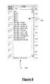
- FIG. 1is a schematic illustration of a setpoint modification monitoring system
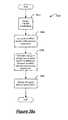
- FIG. 2 ais a flowchart of an algorithm for a setpoint modification monitoring system
- FIG. 2 bis a flowchart of an algorithm for a setpoint modification monitoring system
- FIG. 3is a screenshot of a user interface for a setpoint modification monitoring system
- FIG. 4is a screenshot of a user interface for a setpoint modification monitoring system
- FIG. 5is a screenshot of a user interface for a setpoint modification monitoring system
- FIG. 6is a screenshot of a user interface for a setpoint modification monitoring system
- FIG. 7is a screenshot of a user interface for a setpoint modification monitoring system
- FIG. 8is a screenshot of a user interface for a setpoint modification monitoring system
- FIG. 9is a screenshot of a user interface for a setpoint modification monitoring system
- FIG. 10is a screenshot of a user interface for a setpoint modification monitoring system
- FIG. 11is a screenshot of a user interface for a setpoint modification monitoring system
- FIG. 12is a screenshot of a user interface for a setpoint modification monitoring system
- FIG. 13is a screenshot of a user interface for a setpoint modification monitoring system
- FIG. 14is a screenshot of a user interface for a setpoint modification monitoring system
- FIG. 15is a screenshot of a user interface for a setpoint modification monitoring system
- FIG. 16is a screenshot of a user interface for a setpoint modification monitoring system
- FIG. 17is a screenshot of a user interface for a setpoint modification monitoring system
- FIG. 18is a screenshot of a user interface for a setpoint modification monitoring system
- FIG. 19is a screenshot of a user interface for a setpoint modification monitoring system
- FIG. 20is a screenshot of a user interface for a setpoint modification monitoring system
- FIG. 21is a screenshot of a user interface for a setpoint modification monitoring system
- FIG. 22is a screenshot of a user interface for a setpoint modification monitoring system
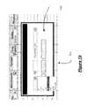
- FIG. 23is a screenshot of a user interface for a setpoint modification monitoring system
- FIG. 24is a screenshot of a user interface for a setpoint modification monitoring system
- FIG. 25is a screenshot of a user interface for a setpoint modification monitoring system
- FIG. 26is a screenshot of a user interface for a setpoint modification monitoring system
- FIG. 27is a screenshot of a user interface for a setpoint modification monitoring system
- FIG. 28is a screenshot of a user interface for a setpoint modification monitoring system
- FIG. 29is a screenshot of a user interface for a setpoint modification monitoring system
- FIG. 30is a screenshot of a user interface for a setpoint modification monitoring system
- FIG. 31is a screenshot of a user interface for a setpoint modification monitoring system
- FIG. 32is a screenshot of a user interface for a setpoint modification monitoring system
- FIG. 33is a screenshot of a user interface for a setpoint modification monitoring system
- FIG. 34is a screenshot of a user interface for a setpoint modification monitoring system
- FIG. 35is a screenshot of a user interface for a setpoint modification monitoring system
- FIG. 36is a screenshot of a user interface for a setpoint modification monitoring system
- FIG. 37is a flowchart of an algorithm for a setpoint modification monitoring system
- FIG. 38 ais a flowchart of an algorithm for a setpoint modification monitoring system
- FIG. 38 bis a flowchart of an algorithm for a setpoint modification monitoring system
- FIG. 38 cis a flowchart of an algorithm for a setpoint modification monitoring system
- FIG. 39 ais a flowchart of an algorithm for a setpoint modification monitoring system
- FIG. 39 bis a flowchart of an algorithm for a setpoint modification monitoring system
- FIG. 40is a flowchart of an algorithm for a setpoint modification monitoring system
- FIG. 41is a screenshot of a user interface for a setpoint modification monitoring system
- FIG. 42is a flowchart of an algorithm for a setpoint modification monitoring system
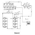
- FIG. 43is a schematic illustration of a refrigeration system
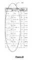
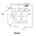
- FIG. 44is a schematic illustration of an HVAC system
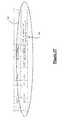
- FIG. 45is a schematic illustration of a lighting system
- FIG. 46is a schematic illustration of an anti-condensate heater system
- FIG. 47is a screenshot of a user interface for a store format wizard.
- FIG. 48is a screenshot of a user interface for a setpoint modification monitoring system.
- modulecontrol module, computer, and/or controller refer to one or more of the following: a processor (shared, dedicated, or group) and memory that execute one or more software or firmware programs or a portion of one or more software or firmware programs; an application specific integrated circuit (ASIC); an electronic circuit; a combinational logic circuit; and/or other suitable components that provide the described functionality.
- computer readable mediummay refer to any medium capable of storing data for a computer or module, including, but not limited to, memory, RAM, ROM, PROM, EPROM, EEPROM, flash memory, CD-ROM, floppy disk, magnetic tape, other magnetic medium, optical medium, or any other device or medium capable of storing data that is readable by a computer.
- the present system and method for monitoring and evaluating equipment operating parameter modificationsprovides a comprehensive tool for remote energy managers or energy specialists to monitor and evaluate equipment operating parameter, or setpoint, modifications made by contractors or other local repair persons or users at local site locations, to approve or reject each setpoint modification made at the local site location, to correspond with local users at the local site locations, to provide further instructions to local users with respect to the setpoint modification, to request additional information regarding the setpoint modification from the local users, to receive requested additional information from the local users, and to confirm whether the local users have agreed or disagreed with rejected setpoint modifications.
- the present system and methodprovides an interface for remote energy managers or energy specialists and local contractors or users to challenge and dispute each other with respect to proposed setpoint modifications.
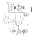
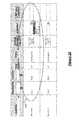
- a setpoint modification monitoring system 100may include a setpoint monitor and server 102 in communication with one or more building system controllers 104 and with a database 106 .
- Setpoint monitor and server 102may be connected to and accessible by one or more computer terminals 108 / 109 through a connected network 110 , such as a LAN, a WAN, the Internet, or other suitable network.
- Computer terminals 108 / 109may access setpoint monitor and server 102 , and the data stored within database 106 , through a web-based user interface, as shown in FIGS. 3-25 and 27 - 36 and described in further detail below.
- a single controller 104may control one or more building systems 120 , 122 , 124 , 126 located at a particular location or site 130 .
- a single controller 104may control both a refrigeration system 120 and an ACH system 122 .
- a single controller 104may also control both a lighting system 124 and an HVAC system 126 .
- the controllers 104may be Einstein or E2 controllers available from Computer Process Controls, Inc., 1640 Airport Road, Suite # 104, Kennesaw, Ga., 31044, such as the E2 RX refrigeration controller, the E2 BX HVAC controller, or the E2 CX convenience store controller.
- a single controller 104may control a single building system, such as refrigeration system 120 , ACH system 122 , lighting system 124 , or HVAC system 126 or any combination of refrigeration system 124 , ACH system 122 , lighting system 124 , or HVAC system 126 . While only one of the sites 130 is expanded in FIG. 1 to show controllers 104 and building systems 120 , 122 , 124 , 126 , it is understood that each of the sites may include controllers 104 and building systems 120 , 122 , 124 , 126 .
- Controller 104may store setpoints for any building systems 120 , 122 , 124 , 126 under its control and may operate any building systems 120 , 122 , 124 , 126 under its control according to the stored setpoints.
- Controller 104may communicate with setpoint monitor and server 102 through network 110 .
- setpoint monitor and server 102may poll controllers 104 at each of the sites 130 to determine whether any setpoints have been modified at that particular controller 104 .
- Setpoint monitor and server 102may compare all setpoints associated with a particular controller 104 with the setpoints previously stored in database 106 for that particular controller 104 to determine whether any setpoints have been modified.
- controllers 104may store a setpoint modification flag indicating setpoint modifications have been made at that particular controller 104 .
- Controllers 104may also maintain a log of setpoint modifications. In such case setpoint monitor and server 102 can check the log each time it polls the particular controller 104 to determine whether any setpoint modifications have occurred since the last time the particular controller 104 was polled.
- controllers 104may be configured to initiate communication with setpoint monitor and server 102 to alert setpoint monitor and server 102 each time a setpoint modification is made at the controller.
- setpoint monitor and server 102may, at any time, have the most current and up-to-date data with respect to the setpoints associated with each controller 104 .
- controllers 104may be configured to report to setpoint monitor and server 102 at predetermined time intervals (e.g., once per day or once per hour) to update setpoint monitor and server 102 as to any setpoint modifications since the last report.
- each controller 104may communicate all of its associated setpoints to setpoint monitor and server 102 at the predetermined time. Setpoint monitor and server 102 can then compare each setpoint with the previously stored setpoints to determine whether a setpoint modification has occurred.
- each controller 104may communicate setpoint modifications to setpoint monitor and server 102 at the predetermined time.
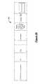
- Exemplary building systemsare described with reference to FIGS. 43-46 .
- a refrigeration system 120may include refrigeration cases 4300 , as well as a plurality of compressors 4302 piped together.
- a discharge output of each compressormay include a respective compressor temperature sensor 4304 .
- a suction inletmay include both a suction pressure sensor 4306 and a suction temperature sensor 4308 .
- a discharge outletmay include a compressor discharge pressure sensor 4310 .
- the various sensorsmay be connected to controller 104 which controls and monitors compressor operation.
- Compressors 4302compress refrigerant vapor that is delivered to a condenser 4320 .
- Condenser fans 4322may enable improved heat transfer from the condenser 4320 .
- Condenser 4320may include an associated ambient temperature sensor 4324 , a condenser temperature sensor 4326 , and a condenser discharge pressure sensor 4328 .
- the various sensorsmay each be connected to the controller 104 which controls condenser fan operation.
- Each refrigeration case 4300may include its own evaporator 4330 , its own expansion valve 4332 for controlling the superheat of the refrigerant, and its own temperature sensor 4334 .
- a case controller 4340may control the refrigeration cases 4300 and may be connected to controller 104 . Additional case controllers 4340 may be used as needed. Alternatively, controller 104 may control refrigeration cases 4300 directly. Refrigerant passes through expansion valve 4332 where a pressure drop causes the high pressure liquid refrigerant to achieve a lower pressure combination of liquid and vapor.
- the temperature sensor 4334may be connected to the case controller 4340 which communicates with controller 104 .
- controller 104may receive operating data for the refrigeration system 120 from the respective temperature, pressure, and current sensors.
- the operating dataalong with various operating parameters such as the stored setpoints, may be used by the controller 104 to operate refrigeration system 120 .
- a usermay input setpoint modifications into controller 104 .
- HVAC system 126may include a fan 4402 as well as a cooling apparatus 4404 , a heating apparatus 4406 , and a damper 4408 , if appropriate. Controller 104 may control the fan 4402 , cooling apparatus 4404 , heating apparatus 4406 , and damper 4408 to heat or cool as desired.
- a temperature sensor 4410may indicate a temperature of air exiting the cooling apparatus 4404 or heating apparatus 4406 .
- a room temperature sensor 4414may be placed proximate a heated/cooled area. Controller 104 may receive temperature data from temperature sensor 4414 .
- a usersuch as a contractor, may input setpoint modifications into controller 104 .
- a lighting system 124may include one or more lighting fixtures 4502 which communicate with controller 104 .
- Lighting fixtures 4502are shown in various areas of the building and its exterior, with some areas including multiple types of fixtures.
- a sales area 4502 , a department area 4506 , and a parking lot 4508each include lighting fixtures 4502 .
- the department area 4506may include lighting fixtures 4502 for a display case 4510 therein.
- Parking lot 4508may include lighting fixtures 4502 as well as exterior sign lighting 4512 .
- Parking lot lighting fixtures 4502may be equipped with a light sensor 4514 and configured to turn on at dusk.
- a usersuch as a contractor, may input setpoint modifications into controller 104 .
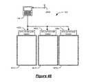
- an ACH system 122may include anti-condensate heaters 4602 in communication with controller 104 .
- Controller 104may receive dew point data from a dew point sensor 4604 .
- controller 104may receive temperature and relative humidity data from temperature and relative humidity sensors and calculate the dew point.
- Controller 104may operate anti-condensate heaters 4602 based on the dew point to heat glass refrigeration case displays 4610 to prevent condensation.
- a usersuch as a contractor, may input setpoint modifications into controller 104 .
- setpoint modificationsmay be received.
- setpoint monitor and server 102may poll controllers 104 to detect setpoint modifications.
- controllers 104may report setpoint modifications to setpoint monitor and server 102 .
- setpoint monitor and server 102may display a current setpoint value and a benchmark value for each “pending” setpoint modification received.
- the benchmark value for a particular setpointmay be the last accepted or approved value for the benchmark. If a value for the particular setpoint has not yet been accepted or approved, the benchmark value may be displayed as “not set.”
- “pending” setpoint modificationare displayed.
- “Pending” setpoint modificationsare setpoint modifications that have not yet been “approved” by an energy specialist.
- the benchmark valueis 155.0 PSI.
- the current, or modified, value of the setpointis 165.0 PSI.
- a list of suction pressure setpointsis displayed. As indicated at 1300 , a particular suction pressure setpoint has been modified from a previous benchmark value of 66.0 PSI to 40.0 PSI.
- setpoint monitor and server 102may receive “approve” or “reject” input from an energy specialist for each setpoint modification.
- an energy specialist or energy managermay login to the setpoint monitor and server 102 .
- Energy specialistsin particular may review the listing of setpoint modifications and either “approve” or “reject” each of the modifications.
- FIGS. 5 and 6show the same screen shot.
- FIG. 5shows the left hand portion of the screen and
- FIG. 6shows the right hand portion of the same screen.
- a “rejected” setpoint modificationis also shown in the screenshots of FIGS. 13 , 14 , 16 , 17 , 21 , and 24 .
- setpoint monitor and server 102may update the “benchmark setpoint value” for each “approved” setpoint modification. For each setpoint modification that is “approved” by an energy specialist, setpoint monitor and server 102 may update the value in the database 106 associated with the particular setpoint to reflect the modification. For example, if a pressure control setpoint is modified from a benchmark value of 155.0 PSI to a value of 165.0 PSI, and if an energy specialist “approves” the modification, setpoint monitor and server 102 may update database 106 to reflect the modification, storing the 165.0 PSI as the new benchmark value for that setpoint. Further, in block 208 , setpoint monitor and server 102 may remove any “approved” modifications from the list of “pending” setpoint modifications. Setpoint monitor and server 102 may also remove the “approved” modification from the display list.
- setpoint monitor and server 102may receive comments from an energy specialist regarding the rejection.
- the proposed setpoint modificationhas been rejected and the energy specialist has entered the comment “Return to PSI/Temp Modified strategy with Hi limit set for 75 and low limit set for 55 and TD setting set for 18. This should allow for 70 degree condensing.”
- the proposed setpoint modificationhas been rejected and the energy specialist has entered the comment “Return suction Pressure Setpoint to benchmark, per store specification.”
- the proposed setpoint modificationhas been rejected and the energy specialist has entered the comment “What is reason for increasing setpoint?”.
- the “comments”may include questions directed to the contractor or person that made the setpoint modification.
- the proposed setpoint modificationhas been rejected and the energy specialist has entered the comment “Setpoints below 68 are not allowed.”
- setpoint monitor and server 102may notify the appropriate contractors of any “rejected” setpoint modifications.
- an energy specialistmay direct the setpoint monitor and server 102 to notify contractors.
- FIG. 25a listing of contractors for notification is shown, along with corresponding emails address and data with respect to the total number of exceptions, the number of approved modifications, the number of rejected modifications, the number of unaddressed modifications, and the date and time of the last email sent.
- 26shows an example email that may be sent by the setpoint monitor and server 102 to a particular contractor (e.g., contractor 1 ) notifying the contractor that setpoint exceptions are available for the contractor to review and providing a link to the setpoint monitor and server web address where the exceptions can be viewed.
- a particular contractore.g., contractor 1
- FIG. 2 bdiffers from FIG. 2 a in that FIG. 2 b includes block 211 .
- setpoint monitor and server 102may group “rejected” setpoint modification according to a designated criteria before notifying the contractor in block 212 .
- setpoint monitor and server 102may group all “rejected” setpoint modifications for a specific system, such as a refrigeration system or an HVAC system.
- setpoint monitor and server 102may then notify the contractor or contractors of the setpoint modifications for the grouped set of “rejected” setpoint modifications all at once.
- setpoint monitor and server 102may group all “rejected” setpoint modifications for a specific contractor. In block 212 , setpoint monitor and server 102 may then notify that contractor of the grouped set of “rejected” setpoint modifications associated with that contractor all at once.
- setpoint monitor and server 102may receive “agree” or “disagree” input from contractors for any setpoint modifications that were previously “rejected” by an energy specialist. As shown in FIGS. 27-29 , a listing of previously “rejected” setpoint modifications is displayed for a contractor. As shown in FIG. 28 , the contractor can either “Agree” or “Disagree” with the energy specialist.
- the setpoint monitor and server 102may remove the previously rejected modification from the “pending” modifications.
- the contractorBy “agreeing” with the energy specialist, the contractor is indicating that the setpoint will be returned to its original value that it had prior to the proposed setpoint modification. For example, in the first row of the listing in FIG. 29 , the contractor has agreed with the energy specialist and will change the “minimum temperature setpoint” from its current value of 80.0 degrees Fahrenheit back to its original benchmark value of 65.0 degrees Fahrenheit. Alternatively, the setpoint may be returned to its original or benchmark value, or some other value, remotely by the energy specialist or another person in charge of changing setpoints.
- the modificationmay appear in a “Pending Fix” state.
- the modificationmay remain in the “Pending Fix” state until the next time the particular controller 104 communicates with setpoint monitor and server 102 and the setpoint is confirmed to have been returned to the original or benchmark value.
- setpoint monitor and server 102may receive a “contractor comment” with respect to the “disagreement.”
- a contractorhas commented that “I changed setpoint because doors were sweaty.”
- a contractorhas commented that “Doors were sweaty” indicating that this was the reason for the setpoint modification.
- the contractor's commentsprovide an explanation to the energy specialist as to why the setpoint was modified in the first place.
- the energy specialistmay ultimately approve the setpoint modification by changing the initial “rejection” to an “approval.”
- setpoint monitor and servermay return to block 202 to receive additional setpoint modifications and display “pending” setpoint modifications in block 204 .
- the setpoint monitor and server, energy specialist or energy manager, and contractormay iteratively review the status of pending setpoint modifications.
- a contestmay arise between an energy specialist and a contractor with respect to certain challenged setpoint modifications and with respect to the reasons for the modification and the reasons for returning the setpoint modification to its original or benchmark value.
- a pending setpoint modificationwill remain challenged or pending until an energy specialist “approves” the modification or until a contractor “agrees” to return the setpoint to its original or benchmark value.
- an energy specialist and a contractormay agree to a compromise value for the particular setpoint.
- a login screen for the setpoint monitor and serveris shown.
- the login processmay require a Login ID or user ID and a Password.
- Usersmay be categorized as “Energy Specialists”, “Energy Managers”, or “Contractors.”
- Energy Specialistsmay be responsible for approving or rejecting setpoint modifications.
- Energy Managersmay be able to access and create various reports, as discussed in further detail below.
- Contractorsmay be on-site and may be responsible for setting and modifying setpoints at the location of particular sites 130 . Additionally, a particular user may be categorized as both an Energy Manager and an Energy Specialist.
- the user interfacemay be a web-based user interface, accessible by pointing an internet browser to a url associated with the setpoint monitor and server.
- a url for logging in and accessing the setpoint monitor and serveris shown as: http://www.webpage-url-for-set-point-monitor-server.com.
- a menu of options 402may be presented. Additionally, a list of “sites” 400 which the user has access to may be provided. As shown in FIG. 4 , by clicking on the “+” next to the “sites”, the list of sites may be expanded.
- the menu of options 402may include only those options/actions available to the particular user. For example, Energy Manager users may see only Energy Manager options/actions. Energy Specialist users may see only Energy Specialist options/actions. Contractors may see only Contractor options/actions.
- the particular userqualifies as both an Energy Specialist and an Energy Manager.
- the Energy Specialist options/actionsmay include “Approve/Reject Changes,” “Notify Contractors,” and “Setpoint Resolution Failures.”
- the Energy Manager options/actionsmay include “Benefit Loss Summary,” “Contractor Scorecard,” “Most Changes Scorecard,” “Most Losses Scorecard,” “Setpoint Exceptions Report,” and “View Contractor Exceptions.”
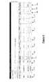
- the “Approve/Reject Changes” option from the “Energy Specialist” menuhas been selected.
- the “Approve/Reject Changes” windowallows for entry of a desired date range. For example, in FIG. 5 the “From” date is set to “Mar. 1, 2009” and the “To” date is set to “Mar. 31, 2009.” Further, the “Approve/Reject Changes” window shows setpoint modifications within the entered date range. FIG. 5 , shows the left hand portion of the row. FIG. 6 shows the right hand portion of the same “Approve/Reject Changes” window.
- each setpoint modification entrymay be shown in a single horizontal row of the chart, showing data for: Site 500 , Contractor 502 , Verification Date 504 , Original Change date 506 , Unit 508 , Application Type 510 , Application Instance 512 , Setpoint 514 , Benchmark setpoint 516 , Current setpoint 518 , Units 520 , State 522 , Response by Energy Specialist 524 , Energy Specialist Comment 600 , and Contractor Comment 602 .
- each entryincludes a “filter out” button 604 to filter out the particular entry from the display.
- the Site 500corresponds with the site where the equipment corresponding with the particular setpoint modification is located.
- the Contractor 502corresponds with the particular contractor responsible for the particular setpoint modification.
- a single sitemay have one or more contractors that perform service on equipment at the site.
- the Verification Date 504corresponds with the date and time when the setpoint monitor and server 102 last verified the current value of the particular setpoint.
- the Original Change date 506corresponds with the date when the setpoint modification was initially made.
- the Unit 508corresponds with the particular unit of equipment corresponding with the particular setpoint modification.
- the Application Type 510corresponds with the particular type of application of the equipment corresponding to the particular setpoint modification.
- the Application Instance 512corresponds with the name of the particular instances of the particular unit of equipment at the site corresponding with the particular setpoint modification.
- the Setpoint 514corresponds with the particular setpoint that is the subject of the particular setpoint modification.
- the Benchmark setpoint 516corresponds with the benchmark or previously approved value for the corresponding setpoint.
- the Current setpoint 518correspond with the current value for the corresponding setpoint.
- the Units 520corresponds with the units for the Benchmark setpoint 516 and Current setpoint 518 values.
- the State 522corresponds with the current state of the corresponding setpoint modification.
- the Response by Energy Specialist 524corresponds with the current Energy Specialist response to the corresponding setpoint modification.
- the Energy Specialist Comment 600corresponds with the comment entry field for any Energy Specialist comments on the corresponding setpoint modification.
- the Contractor Comment 602corresponds with the comment entry field for any Contractor comments on the corresponding setpoint modification.
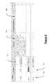
- the State 522 fieldhas been expanded to show the different possible states for a setpoint modification. Selecting a particular state will show the setpoint modifications having that state and will filter out from the display any setpoint modifications that are not in the selected state.
- the possible statesinclude “Pending,” “Challenged,” “Contested,” and “Pending Fix.”
- the “Pending” statecorresponds with setpoint modifications that have not yet been approved or rejected by an Energy Specialist.
- the “Contested” statecorresponds with setpoint modifications that have been rejected by the Energy Specialist.
- the “Challenged” statecorresponds with setpoint modifications that have been rejected by the Energy Specialist and with which the contractor “Disagrees.”
- the “Pending Fix” statecorresponds with setpoint modifications that were rejected by the Energy Specialist and with which the contractor “Agreed.” The setpoint modification will remain in the “Pending Fix” state until the setpoint monitor and server 102 verifies that the setpoint was changed back to its benchmark value.
- the “Pending” state filterhas been selected.
- “Pending” setpoint modificationsare shown.
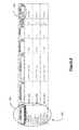
- the Application Type 510has been expanded to show different Application Types, including Air Handler AHU, Anti-Sweat, Condenser, HVAC, HVAC Zones, Lighting, Physical Al, Single Group, Store Hours, Suction Group, and Unit Heater.
- the Unit 508has been expanded to show particular units of equipment that have corresponding setpoint modifications.
- the Application Instance 512has been expanded to show particular application instances that have corresponding setpoint modifications.
- Setpoint 514has been expanded to show particular setpoints that have corresponding setpoint modifications.
- the Response by Energy Specialist 524is being expanded for a particular setpoint modification.
- the suction pressure setpoint for a particular suction grouphas been modified from a benchmark value of 66.0 PSI to a current value of 40.0.
- the “Reject” responseis being selected.
- the setpoint modificationhas been “Rejected” and the Energy Specialist Comment 600 is being filled in for the particular setpoint modification as follows: “Return suction Pressure Setpoint to benchmark, per store specification.”
- the Response by Energy Specialist 524is being expanded for a particular setpoint modification.
- the pressure control setpoint for a particular condenser applicationhas been modified from a benchmark value of 160.0 PSI to a current value of 195.0.
- the “Reject” responseis being selected.
- the setpoint modificationhas been “Rejected” and the Energy Specialist Comment 600 is being filled in for the particular setpoint modification as follows: “What is reason for increasing setpoint?”.
- HVAC Setpointis being selected from the Setpoint 514 field. In this way, once selected, HVAC Setpoints will be shown in the display.
- a particular value filtermay be inputted for the current or benchmark setpoint value fields. For example, in FIG. 19 , input is being received for the Current setpoint 518 to be filtered to show current setpoints that are set “less than” 68 degrees Fahrenheit.
- setpoint modifications with current setpoint values that are less than 68 degrees Fahrenheitare shown.
- “ASW Min. Humidity Setpoint”is being selected from the Setpoint 514 field. In this way, once selected, Anti-Sweat Minimum Humidity Setpoints will be shown in the display.
- the benchmark setpoint valueis 38.0.
- the current setpoint valueis 100.0.
- the stateis “challenged.”
- the Energy Specialisthas “rejected” the change and entered the comment “Return setpoint to benchmark.”
- the contractorhas disagreed with the rejection, and entered a contractor comment: “I changed setpoint because doors were sweaty.”
- the setpoint modificationwill remain in the challenged state until either the Energy Specialist Approves the setpoint modification or the Contractor Agrees with the Energy Specialist and returns the setpoint to the benchmark value. Alternatively, the Energy Specialist and the Contractor may compromise and agree on an intermediate setting.
- the contractorcould “agree” with the Energy Specialists rejection and then modify the setpoint to the new agreed value.
- the new agreed valuewould then generate a new setpoint modification entry.
- the Energy Specialistcould then approve the new setpoint modification entry to arrive at the compromised setpoint value.
- the “Notify Contractors” optionhas been selected and a table of contractors with pending setpoint modification exceptions is shown at 2502 .
- the contractoris listed along with the contractor's email and data with respect to the total number of exceptions, the number of approved setpoint modifications, the number of rejected setpoint modifications, the number of unaddressed setpoint modifications, and the date and time the last email was sent to the particular contractor.
- the contractorsare notified via email of setpoint exceptions.
- FIG. 26an example email to a contractor as a result of selecting the “Notify Contractors” option is shown.
- the emailnotifies the contractor that the contractor's attention is needed on setpoint exceptions.
- the emailprovides a link to the web based user interface of the setpoint monitor and server 102 so that the contractor can click on the link, login to the setpoint monitor and server, and address any pending setpoint exceptions, i.e., any setpoint modifications that have been rejected by an Energy Specialist.
- the contractormay be notified in one email of all setpoint exceptions associated with that contractor that are currently outstanding.
- the contractormay be notified of the grouped set of “rejected” setpoint modifications all at once.
- the Contractorhas “Agreed” with the Energy Specialist. In other words, the Contractor has agreed to return the setpoint to the benchmark value. The setpoint modification appears in the “Pending Fix” state.
- a setpoint resolution failures table 3000is displayed.
- the tableshows particular contractors and particular sites, along with the City and State corresponding to the particular Site. Further, the table shows the Result that caused the failure, i.e., setpoint resolution procedure was never ran, or the setpoint resolution procedure failed a number of times. Further, the table shows the last time the setpoint resolution procedure succeeded.
- menu options for an Energy Managerare shown at 3100 and include: “Benefit Loss Summary,” “Contractor Scorecard,” “Most Changes Scorecard,” “Most Losses Scorecard,” “Setpoint Exceptions Report,” and “View Contractor Exceptions.” By selecting one or more of these options, an Energy Manager may view various reports related to estimated energy consumption benefits and losses resulting from setpoint modifications. An Energy manager may also view reports related to the number of modifications and number of outstanding exceptions, etc.
- setpoint monitor and server 102may estimate energy consumption of a particular piece of equipment or grouping of pieces of equipment operating at a benchmark setpoint value.
- setpoint monitor and server 102may estimate energy consumption of a suction group having one or more compressors, a condenser or condenser group having one or more condensers, or an anti-sweat heater or anti-sweat heater group having one or more anti-sweat heaters.
- setpoint monitor and server 102may estimate energy consumption of the particular piece of equipment or grouping of pieces of equipment operating at the current setpoint value.
- setpoint monitor and server 102may estimate an expected increase or decrease in energy consumption based on the change in the setpoint value to the current value by comparing the results of the estimate from block 3702 with the results of the estimate from block 3704 .
- a 10 ton compressor rackmay use around 15 KW of electricity when operating at a suction pressure setpoint of 50 PSI.
- a 1 PSI suction pressure setpoint change for the rackmay result in a 1.5% increase in energy usage.
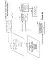
- Benchmark setpoint data 3802 and current setpoint data 3804may be retrieved from database 106 .
- Benchmark setpoint data 3802may include benchmark setpoint values for setpoints such as: suction pressure setpoint, control temperature setpoint, enable setpoint float, refrigerant type, float temperature, float maximum pressure, float minimum pressure, float maximum temperature, float minimum temperature, or any other applicable setpoint.
- Current setpoint data 3804may likewise include current setpoint values for setpoints such as: suction pressure setpoint, control temperature setpoint, enable setpoint float, refrigerant type, float temperature, float maximum pressure, float minimum pressure, float maximum temperature, float minimum temperature, or any other applicable setpoint.
- setpoint monitor and server 102may determine an active benchmark suction setpoint using specific rules for the specific type of controller used with the particular suction group.
- setpoint monitor and server 102may determine an active current suction setpoint using specific rules for the specific type of controller used with the particular suction group.
- setpoint monitor and server 102may calculate an effective average benchmark suction pressure over a predetermined time period.
- setpoint monitor and server 102may calculate a current average suction pressure setting. In this way, blocks 3802 , 3806 , and 3810 relate to benchmark setpoint values and blocks 3804 , 3808 , and 3812 relate to current setpoint values.
- setpoint monitor and server 102may apply controller type specific rules, corresponding to the specific type of controller used with the particular suction group, about the change of state between the benchmark value or values, e.g., the average benchmark suction pressure from block 3810 , and the current value or values, e.g., the current average suction pressure setting from block 3812 .
- setpoint monitor and server 102may calculate an effective average change in the suction pressure setting, for example.
- setpoint monitor and server 102may calculate a rack base load using site or store format information or additional configuration information.
- setpoint monitor and server 102may calculate a KW change based, for example, on the calculated effective average change in the suction pressure setting from block 3816 and the calculated rack base load from block 3818 . In this way, setpoint monitor and server 102 may calculate an estimated change in energy consumption based on a setpoint modification for a suction group.
- Benchmark setpoint data 3832 and current setpoint data 3834may be retrieved from database 106 .
- Benchmark setpoint data 3832may include benchmark setpoint values for setpoints such as: control type, condenser type, pressure control setpoint, temperature control setpoint, temperature difference setpoints, minimum temperature setpoint, refrigeration type, or any other applicable setpoint.
- Current setpoint data 3834may likewise include current setpoint values for setpoints such as: control type, condenser type, pressure control setpoint, temperature control setpoint, temperature difference setpoints, minimum temperature setpoint, refrigeration type, or any other applicable setpoint.
- setpoint monitor and server 102may determine an active benchmark condenser operating pressure setpoint using specific rules for the specific type of controller used with the particular condenser or condenser group.
- setpoint monitor and server 102may determine an active current condenser operating pressure setpoint using specific rules for the specific type of controller used with the particular condenser or condenser group.
- setpoint monitor and server 102may calculate an effective average benchmark condenser operating pressure setpoint over a predetermined time period.
- setpoint monitor and server 102may calculate a current average condenser operating pressure setpoint. In this way, blocks 3832 , 3836 , and 3840 relate to benchmark setpoint values and blocks 3834 , 3838 , and 3842 relate to current setpoint values.
- setpoint monitor and server 102may apply controller type specific rules, corresponding to the specific type of controller used with the particular condenser or condenser group, about the change of state between the benchmark value or values, e.g., the average benchmark condenser operating pressure setpoint from block 3840 , and the current value or values, e.g., the current average condenser operating pressure setpoint from block 3842 .
- setpoint monitor and server 102may calculate an effective average change in the condenser operating pressure, for example.
- setpoint monitor and server 102may calculate a rack base load using site or store format information or additional configuration information.
- setpoint monitor and server 102may calculate a KW change based, for example, on the calculated effective average change in condenser operating pressure from block 3846 and the calculated rack base load from block 3848 . In this way, setpoint monitor and server 102 may calculate an estimated change in energy consumption based on a setpoint modification for a condenser or condenser group.
- Benchmark setpoint data 3862 and current setpoint data 3864may be retrieved from database 106 .
- Benchmark setpoint data 3862may include benchmark setpoint values for setpoints such as: output, ASW maximum humidity setpoint, ASW minimum humidity setpoint, full on dewpoint, full off dewpoint, minimum output, maximum output, or any other applicable setpoint.
- Current setpoint data 3864may likewise include current setpoint values for setpoints such as: output, ASW maximum humidity setpoint, ASW minimum humidity setpoint, full on dewpoint, full off dewpoint, minimum output, maximum output, or any other applicable setpoint.
- setpoint monitor and server 102may calculate an effective average benchmark anti-sweat heater output percentage on time using controller type specific rules, corresponding to the specific type of controller used with the particular anti-sweat heater or anti-sweat heater group over a predetermined time period.
- setpoint monitor and server 102may calculate an effective average current anti-sweat heater output percentage on time using controller type specific rules, corresponding to the specific type of controller used with the particular anti-sweat heater or anti-sweat heater group over a predetermined time period. In this way, blocks 3862 and 3870 relate to benchmark setpoint values and blocks 3864 and 3872 relate to current setpoint values.
- setpoint monitor and server 102may calculate an effective average change in anti-sweat heater output percentage on time, for example.
- setpoint monitor and server 102may calculate an anti-sweat full on load using site or store format information or additional configuration information.
- setpoint monitor and server 102may calculate a KW change based, for example, on the calculated effective average change in anti-sweat heater output percentage on time from block 3876 and the calculated anti-sweat heater full on load from block 3878 . In this way, setpoint monitor and server 102 may calculate an estimated change in energy consumption based on a setpoint modification for an anti-sweat heater or anti-sweat heater group.
- setpoint monitor and server 102may receive setpoint modifications.
- setpoint monitor and server 102may compare the modified setpoint value with previous benchmark value.
- setpoint monitor and server 102may calculate a change in energy consumption based on the difference between the modified setpoint and the previous benchmark.
- setpoint monitor and server 102may display the change in energy consumption calculated in block 3906 .
- setpoint monitor and server 102may receive setpoint modifications.
- setpoint monitor and server 102may calculate a change in energy consumption based on the difference between the modified setpoint and the previous benchmark.
- setpoint monitor and server 102may rank or prioritize all pending setpoint modifications according to a calculated change in energy consumption associated with the setpoint modification. For example, setpoint modifications may be ranked such that the setpoints modifications with the highest corresponding increase in energy consumption may be ranked highest.
- Setpoint modifications with a lower corresponding increase in energy consumptionmay be ranked lower in priority.
- Setpoint modifications that do not effect energy consumptionmay be ranked lower still.
- Setpoint modifications that decrease energy consumptionmay be ranked lower still.
- Setpoint monitor and server 102may then display the setpoint modifications, as described above, in order of priority according to the ranking. In this way, energy managers or energy specialists may be presented with the setpoint modifications in order of priority according to the ranking and may perform their analysis, including approval, rejections, etc., according to the established order of priority.
- setpoint monitor and server 102may also categorize the setpoint modifications. For example, setpoints modifications with a corresponding increase in energy consumption that is greater than a predetermined threshold may be categorized in a “high priority” or “urgent” category. When a high priority setpoint modification is received, setpoint monitor and server 102 may notify or alert an energy manager or energy specialist as appropriate.
- the Benefit-Loss Summary Reportmay be selected from the Energy Manager menu options 3100 , as shown in FIG. 31 .
- the Benefit-Loss Summary Reportmay include date range entry fields. In this case, March 2009 has been inputted as the “From” date and April 2009 has been inputted as the “To” date.
- the Benefit-Loss Summary Reportmay include a Benefit Summary table 3202 and a Leakage Summary table 3204 .
- the Benefit Summary table 3202may summarize energy savings, or “benefits,” resulting from setpoint modifications being reverted to benchmark setpoint values over the specified time periods.
- Benefit Summary table 3202may include data for changes reverted prior to the specified time period, e.g., prior to March 2009, data for changes reverted during the specified time period, e.g., between March 2009 and April 2009, and data for all changes reverted to the end of the specified time period, e.g., all changes reverted through April 2009.
- the Benefit Summary table 3202may include the total count of reverted setpoint modifications, i.e., the total number of times a setpoint modification was changed back to a benchmark value.
- the Benefit Summary table 3202may also include the total sum of Kilo-Watt Hours (KWH) associated with the reverted changes, the total monetary amount associated with the total KWH, e.g., the total dollar amount, and the annualized monetary amount, e.g., the annualized dollar amount.
- KWHKilo-Watt Hours
- the total monetary amount and the annualized dollar amountmay be based on applicable energy costs for the associated local site.
- setpoint monitor and server 102may apply energy cost data to the estimated/calculated energy savings data, to display the total dollar cost savings and the annualized dollar cost savings associated with the reverted setpoint modifications in the Benefit Summary table 3202 .
- the Benefit Summary table 3202may display the total and annualized monetary savings associated with having reverted setpoint modifications over the specified time period.
- Leakage Summary table 3204may summarize energy losses or “leakages” resulting from setpoint modifications not being reverted to benchmark setpoint values over the specified time periods.
- Leakage Summary table 3204may include data for changes that were not reverted prior to the specified time period, e.g., prior to March 2009, data for changes that were not reverted during the specified time period, e.g., between March 2009 and April 2009, and data for all changes that were not reverted to the end of the specified time period, e.g., all changes not reverted through April 2009.
- the Leakage Summary table 3204may include the total count of reverted setpoint modifications that were not reverted, i.e., the total number of times a setpoint modification was not changed back to a benchmark value.
- the Leakage Summary table 3204may also include the total sum of Kilo-Watt Hours (KWH) associated with not having reverted the changes, the total monetary amount associated with the total KWH, e.g., the total dollar amount, and the annualized monetary amount, e.g., the annualized dollar amount.
- KWHKilo-Watt Hours
- the total monetary amount and the annualized dollar amountmay be based on applicable energy costs for the associated local site.
- setpoint monitor and server 102may apply energy cost data to the estimated/calculated energy savings data, to display the total dollar cost and the annualized dollar cost associated with not having reverted setpoint modifications in the Leakage Summary table 3204 .
- the Leakage Summary table 3204may display the total and annualized monetary loss associated with not having reverted setpoint modifications over the specified time period.
- a Contractor Scorecard 3300is shown.
- the Contractor Scorecard 3300may be selected from the Energy Manager menu options 3100 , as shown in FIG. 31 .
- the Contractor Scorecard 3300may include date range entry fields. In this case, March 2009 has been inputted as the “From” date and April 2009 has been inputted as the “To” date.
- the Contractor Scorecard 3300may display, in bar graph format and in table format, the number of setpoint modifications that were approved, the number of setpoint modifications that are currently pending review by an Energy Specialist, the number of setpoint modifications that were reverted or reset to the benchmark setpoint value, and the total number of unresolved setpoint modifications.
- the Setpoint Most Changes Scorecard 3400may be selected from the Energy Manager menu options 3100 , as shown in FIG. 31 .
- the Setpoint Most Changes Scorecard 3400may include date range entry fields. In this case, March 2009 has been inputted as the “From” date and April 2009 has been inputted as the “To” date.
- the Setpoint Most Changes Scorecard 3400may display the contractors with the most setpoint changes or modifications in a bar graph format. Alternatively, the Setpoint Most Changes Scorecard 3400 may display the contractors with the most setpoint changes or modifications in a table format.
- the Setpoint Most Losses Scorecard 3500may be selected from the Energy Manager menu options 3100 , as shown in FIG. 31 .
- the Setpoint Most Losses Scorecard 3500may include date range entry fields. In this case, March 2009 has been inputted as the “From” date and April 2009 has been inputted as the “To” date.
- the Setpoint Most Losses Scorecard 3500may display the contractors that have the most associated energy losses resulting from not having reverted setpoint modifications to benchmark values.
- the datamay be displayed in a bar graph format showing total monetary amount lost.
- the Setpoint Most Losses Scorecard 3500may display the contractors with the most losses in a table format.
- a Setpoint Exceptions Report 3600is shown.
- the Setpoint Exceptions Report 3600may be selected from the Energy Manager menu options 3100 , as shown in FIG. 31 .
- the Setpoint Exceptions Report 3600may include date range entry fields. In this case, March 2009 has been inputted as the “From” date and April 2009 has been inputted as the “To” date.
- the Setpoint Exceptions Report 3600may display all setpoint exceptions for the inputted time period. Similar to the “Approve/Reject Changes” display, discussed above with respect to FIGS. 5 and 6 , the Setpoint Exceptions Report 3600 may include, for each setpoint exception, the site, the contractor, the verification date, the original change date, the application type, the application instances, the particular setpoint, the benchmark setpoint value, the current setpoint value, the units of the setpoint values, the current state, the Energy Specialist's comments, and the Contractor's comments.
- an Energy Specialistmay approve or reject setpoint modifications made by a contractor.
- Setpoint monitor and server 102may notice or monitor trends that develop in the approval or rejection of setpoint modifications and may suggest rules to apply to future setpoint modifications. Once certain rules are developed, future setpoint modifications may be automatically approved or rejected based on the rule. Further, an Energy Specialist may enter a rule for application to future setpoint modifications.
- setpoint monitor and server 102may receive setpoint modifications.
- setpoint monitor and server 102may store setpoint modifications, along with the Energy Specialist's response (e.g., approve or reject) in database 106 .
- setpoint monitor and server 102may search setpoint modification database 106 for similar setpoint modifications and may review the Energy Specialist's previous response.
- setpoint monitor and server 102may suggest a setpoint modification rule based on similar modifications or trends in setpoint modifications and the Energy Specialist's response.
- setpoint monitor and server 102may receive the Energy Specialist's response to the suggested rule.
- setpoint monitor and server 102may add the new setpoint modification rule to database 106 .
- setpoint monitor and server 102may discard the setpoint modification rule or save the rule to be re-suggested in the future.
- setpoint monitor and server 102may determine and suggest new setpoint modification rules to be applied to future setpoint modifications made by Contractors.
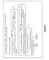
- FIG. 41a screenshot of a rule suggestion window is shown.
- setpoint monitor and server 102has observed that: “It seems that for ‘ComTrol XML’ controllers whenever the ‘SUCT PRESS SETPT’ is lowered by more than 1.7 psi you reject the setpoint change.”
- setpoint monitor and server 102has suggested four options.
- An Energy Specialistmay select one of the suggested options.
- setpoint monitor and server 102suggests to automatically apply a rule to “Site 1 ” and reject all changes where the “SUCT PRESS SETPT” has been lowered by more than 1.7 psi for ComTrol Xml Controllers.
- the usermay modify the suggested rule to apply to additional or different sites. Further, the user may modify the suggested rule to apply for psi modifications different than the suggested 1.7 psi. Further, the user may modify the suggested rule to apply to additional or different controllers than the suggested “ComTrol Xml” controller.
- setpoint monitor and server 102suggests to automatically apply the same rule as in the first option except that the applicable setpoint modifications will be marked for rejection, but the Energy Specialist will ultimately use the approve/reject page to accept or reject all setpoint modifications, including the setpoint modifications marked by the rule.
- the usercan indicate that the suggested rule is a reasonable rule, but withhold final judgment as to whether to accept the rule for a later time. Further, the user can request that no additional rules be suggested for the day. In this way, the user may delay making a final decision with respect to the suggested rule.
- the usercan reject the rule outright.
- setpoint monitor and server 102receives a setpoint modification.
- setpoint monitor and server 102compares the setpoint modification to the setpoint modification rules in the database.
- setpoint monitor and server 102determines whether the current setpoint modification satisfies any rule in the database.
- setpoint monitor and serveraccepts or rejects the current setpoint modification according to the rule.
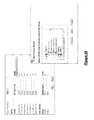
- a particular retailermay have multiple stores at multiple sites. Further, a particular retailer may use a similar format, including similar naming conventions, for the implementation of various building systems and various pieces of equipment at each of the stores. For example, certain controllers for certain building systems for certain functions or areas of the stores may be similarly named throughout the particular retailer's multiple stores.
- a store format wizardmay be used to reduce data entry and provide a template for the naming and arrangement of particular pieces of equipment and controllers. In this way, a particular retailer may establish a single template and then repeat the use of the template across all of the retailer's multiple stores to insure consistent naming and arrangement. As shown in FIG.
- a particular sitemay be selected as the template site. As shown in FIG. 48 , multiple sites may be selected for building the template site.
- the store format wizardmay then build a template for naming and arrangement of controllers and equipment according to the selected site or sites.
- the templatecan be used for future naming and arrangement of equipment.
Landscapes
- Engineering & Computer Science (AREA)
- General Engineering & Computer Science (AREA)
- Physics & Mathematics (AREA)
- General Physics & Mathematics (AREA)
- Automation & Control Theory (AREA)
- Management, Administration, Business Operations System, And Electronic Commerce (AREA)
- Testing And Monitoring For Control Systems (AREA)
- Air Conditioning Control Device (AREA)
- Remote Monitoring And Control Of Power-Distribution Networks (AREA)
- Selective Calling Equipment (AREA)
Abstract
Description
Claims (19)
Priority Applications (10)
| Application Number | Priority Date | Filing Date | Title |
|---|---|---|---|
| AU2010253739AAU2010253739B2 (en) | 2009-05-29 | 2010-05-28 | System and method for monitoring and evaluating equipment operating parameter modifications |
| CN201080023003.7ACN102449606B (en) | 2009-05-29 | 2010-05-28 | System and method for monitoring and evaluating equipment operating parameter modifications |
| CA2761956ACA2761956C (en) | 2009-05-29 | 2010-05-28 | System and method for monitoring and evaluating equipment operating parameter modifications |
| MX2011012546AMX2011012546A (en) | 2009-05-29 | 2010-05-28 | System and method for monitoring and evaluating equipment operating parameter modifications. |
| PCT/US2010/036601WO2010138831A2 (en) | 2009-05-29 | 2010-05-28 | System and method for monitoring and evaluating equipment operating parameter modifications |
| BRPI1014993ABRPI1014993A8 (en) | 2009-05-29 | 2010-05-28 | system and method for monitoring and evaluating equipment operating parameter modifications |
| EP10781285.1AEP2435917B1 (en) | 2009-05-29 | 2010-05-28 | System and method for monitoring and evaluating equipment operating parameter modifications |
| US12/789,562US8473106B2 (en) | 2009-05-29 | 2010-05-28 | System and method for monitoring and evaluating equipment operating parameter modifications |
| US13/908,625US8761908B2 (en) | 2009-05-29 | 2013-06-03 | System and method for monitoring and evaluating equipment operating parameter modifications |
| US14/310,196US9395711B2 (en) | 2009-05-29 | 2014-06-20 | System and method for monitoring and evaluating equipment operating parameter modifications |
Applications Claiming Priority (2)
| Application Number | Priority Date | Filing Date | Title |
|---|---|---|---|
| US18243609P | 2009-05-29 | 2009-05-29 | |
| US12/789,562US8473106B2 (en) | 2009-05-29 | 2010-05-28 | System and method for monitoring and evaluating equipment operating parameter modifications |
Related Child Applications (1)
| Application Number | Title | Priority Date | Filing Date |
|---|---|---|---|
| US13/908,625ContinuationUS8761908B2 (en) | 2009-05-29 | 2013-06-03 | System and method for monitoring and evaluating equipment operating parameter modifications |
Publications (2)
| Publication Number | Publication Date |
|---|---|
| US20100305718A1 US20100305718A1 (en) | 2010-12-02 |
| US8473106B2true US8473106B2 (en) | 2013-06-25 |
Family
ID=43221114
Family Applications (3)
| Application Number | Title | Priority Date | Filing Date |
|---|---|---|---|
| US12/789,562Active2031-08-27US8473106B2 (en) | 2009-05-29 | 2010-05-28 | System and method for monitoring and evaluating equipment operating parameter modifications |
| US13/908,625ActiveUS8761908B2 (en) | 2009-05-29 | 2013-06-03 | System and method for monitoring and evaluating equipment operating parameter modifications |
| US14/310,196ActiveUS9395711B2 (en) | 2009-05-29 | 2014-06-20 | System and method for monitoring and evaluating equipment operating parameter modifications |
Family Applications After (2)
| Application Number | Title | Priority Date | Filing Date |
|---|---|---|---|
| US13/908,625ActiveUS8761908B2 (en) | 2009-05-29 | 2013-06-03 | System and method for monitoring and evaluating equipment operating parameter modifications |
| US14/310,196ActiveUS9395711B2 (en) | 2009-05-29 | 2014-06-20 | System and method for monitoring and evaluating equipment operating parameter modifications |
Country Status (8)
| Country | Link |
|---|---|
| US (3) | US8473106B2 (en) |
| EP (1) | EP2435917B1 (en) |
| CN (1) | CN102449606B (en) |
| AU (1) | AU2010253739B2 (en) |
| BR (1) | BRPI1014993A8 (en) |
| CA (1) | CA2761956C (en) |
| MX (1) | MX2011012546A (en) |
| WO (1) | WO2010138831A2 (en) |
Cited By (4)
| Publication number | Priority date | Publication date | Assignee | Title |
|---|---|---|---|---|
| US20120296869A1 (en)* | 2011-05-17 | 2012-11-22 | Southern Company Services, Inc. | Energy Information Exchange |
| US20140371917A1 (en)* | 2013-06-13 | 2014-12-18 | Trane International Inc. | System and Method for Monitoring HVAC System Operation |
| US20180280826A1 (en)* | 2017-03-31 | 2018-10-04 | James B. Mitchell | Distillation and Essence Extractor Insert for Beer Brewing Machine |
| US10989427B2 (en) | 2017-12-20 | 2021-04-27 | Trane International Inc. | HVAC system including smart diagnostic capabilites |
Families Citing this family (48)
| Publication number | Priority date | Publication date | Assignee | Title |
|---|---|---|---|---|
| US6892546B2 (en) | 2001-05-03 | 2005-05-17 | Emerson Retail Services, Inc. | System for remote refrigeration monitoring and diagnostics |
| US6668240B2 (en) | 2001-05-03 | 2003-12-23 | Emerson Retail Services Inc. | Food quality and safety model for refrigerated food |
| US6889173B2 (en) | 2002-10-31 | 2005-05-03 | Emerson Retail Services Inc. | System for monitoring optimal equipment operating parameters |
| US7412842B2 (en) | 2004-04-27 | 2008-08-19 | Emerson Climate Technologies, Inc. | Compressor diagnostic and protection system |
| US7275377B2 (en) | 2004-08-11 | 2007-10-02 | Lawrence Kates | Method and apparatus for monitoring refrigerant-cycle systems |
| US20090138313A1 (en) | 2007-05-15 | 2009-05-28 | American Power Conversion Corporation | Methods and systems for managing facility power and cooling |
| US9140728B2 (en) | 2007-11-02 | 2015-09-22 | Emerson Climate Technologies, Inc. | Compressor sensor module |
| DE102007047888A1 (en)* | 2007-11-28 | 2009-08-13 | Sitronic Gesellschaft für elektrotechnische Ausrüstung mbH. & Co. KG | sensor arrangement |
| US20110093493A1 (en) | 2008-10-28 | 2011-04-21 | Honeywell International Inc. | Building management system site categories |
| GB0900268D0 (en)* | 2009-01-08 | 2009-02-11 | Mewburn Ellis Llp | Cooling apparatus and method |
| MX2011012546A (en) | 2009-05-29 | 2012-10-03 | Emerson Retail Services Inc | System and method for monitoring and evaluating equipment operating parameter modifications. |
| CA2934860C (en) | 2011-02-28 | 2018-07-31 | Emerson Electric Co. | Residential solutions hvac monitoring and diagnosis |
| CN104137105B (en) | 2011-12-22 | 2017-07-11 | 施耐德电气It公司 | Analysis of the Effect of Transient Events on Temperature in Data Centers |
| US8964338B2 (en) | 2012-01-11 | 2015-02-24 | Emerson Climate Technologies, Inc. | System and method for compressor motor protection |
| US10025330B2 (en) | 2012-09-21 | 2018-07-17 | Schneider Electric It Corporation | Method and apparatus for characterizing thermal transient performance |
| US9310439B2 (en) | 2012-09-25 | 2016-04-12 | Emerson Climate Technologies, Inc. | Compressor having a control and diagnostic module |
| US9529349B2 (en) | 2012-10-22 | 2016-12-27 | Honeywell International Inc. | Supervisor user management system |
| CN105027138B (en) | 2012-12-27 | 2018-01-26 | 施耐德电气It公司 | Systems and methods for visualizing airflow |
| US9551504B2 (en) | 2013-03-15 | 2017-01-24 | Emerson Electric Co. | HVAC system remote monitoring and diagnosis |
| EP2971989A4 (en) | 2013-03-15 | 2016-11-30 | Emerson Electric Co | DIAGNOSTICS AND SYSTEM FOR HEATING, VENTILATION AND AIR CONDITIONING REMOTE MONITORING |
| US9803902B2 (en) | 2013-03-15 | 2017-10-31 | Emerson Climate Technologies, Inc. | System for refrigerant charge verification using two condenser coil temperatures |
| WO2014160663A1 (en) | 2013-03-27 | 2014-10-02 | Schlumberger Canada Limited | Interface for automation client |
| WO2014165731A1 (en) | 2013-04-05 | 2014-10-09 | Emerson Electric Co. | Heat-pump system with refrigerant charge diagnostics |
| US9971977B2 (en)* | 2013-10-21 | 2018-05-15 | Honeywell International Inc. | Opus enterprise report system |
| JP6561562B2 (en)* | 2014-06-30 | 2019-08-21 | パナソニック インテレクチュアル プロパティ コーポレーション オブ アメリカPanasonic Intellectual Property Corporation of America | Cooking apparatus, information display apparatus, control method, cooking utensil, and computer program |
| US9933762B2 (en) | 2014-07-09 | 2018-04-03 | Honeywell International Inc. | Multisite version and upgrade management system |
| JP2016080197A (en)* | 2014-10-10 | 2016-05-16 | アズビル株式会社 | Setting value changing apparatus and method |
| US10606289B2 (en)* | 2015-08-26 | 2020-03-31 | Honeywell International Inc. | System and approach for validating conditions of a space |
| US10362104B2 (en) | 2015-09-23 | 2019-07-23 | Honeywell International Inc. | Data manager |
| US10209689B2 (en) | 2015-09-23 | 2019-02-19 | Honeywell International Inc. | Supervisor history service import manager |
| US12276420B2 (en) | 2016-02-03 | 2025-04-15 | Strong Force Iot Portfolio 2016, Llc | Industrial internet of things smart heating systems and methods that produce and use hydrogen fuel |
| US11233854B2 (en)* | 2016-02-14 | 2022-01-25 | Signify Holding B.V. | Lighting control data identification |
| US10983507B2 (en) | 2016-05-09 | 2021-04-20 | Strong Force Iot Portfolio 2016, Llc | Method for data collection and frequency analysis with self-organization functionality |
| US11507064B2 (en) | 2016-05-09 | 2022-11-22 | Strong Force Iot Portfolio 2016, Llc | Methods and systems for industrial internet of things data collection in downstream oil and gas environment |
| US11774944B2 (en) | 2016-05-09 | 2023-10-03 | Strong Force Iot Portfolio 2016, Llc | Methods and systems for the industrial internet of things |
| US11327475B2 (en) | 2016-05-09 | 2022-05-10 | Strong Force Iot Portfolio 2016, Llc | Methods and systems for intelligent collection and analysis of vehicle data |
| KR20230157525A (en) | 2016-05-09 | 2023-11-16 | 스트롱 포스 아이오티 포트폴리오 2016, 엘엘씨 | Methods and systems for the industrial internet of things |
| US11237546B2 (en) | 2016-06-15 | 2022-02-01 | Strong Force loT Portfolio 2016, LLC | Method and system of modifying a data collection trajectory for vehicles |
| US9975421B2 (en)* | 2016-07-18 | 2018-05-22 | GM Global Technology Operations LLC | Heated vehicle shutter |
| JP7595319B2 (en) | 2017-08-02 | 2024-12-06 | ストロング フォース アイオーティ ポートフォリオ 2016,エルエルシー | Method and system for detection in an industrial internet of things data collection environment using large data sets |
| US11442445B2 (en) | 2017-08-02 | 2022-09-13 | Strong Force Iot Portfolio 2016, Llc | Data collection systems and methods with alternate routing of input channels |
| WO2019094729A1 (en)* | 2017-11-09 | 2019-05-16 | Strong Force Iot Portfolio 2016, Llc | Methods and systems for the industrial internet of things |
| US20200133254A1 (en) | 2018-05-07 | 2020-04-30 | Strong Force Iot Portfolio 2016, Llc | Methods and systems for data collection, learning, and streaming of machine signals for part identification and operating characteristics determination using the industrial internet of things |
| CA3126601A1 (en) | 2019-01-13 | 2020-07-16 | Strong Force Iot Portfolio 2016, Llc | Methods, systems, kits and apparatuses for monitoring and managing industrial settings |
| CN110045630A (en)* | 2019-05-29 | 2019-07-23 | 四川长虹电器股份有限公司 | Smart home system and its monitoring method |
| US11886153B2 (en)* | 2020-07-23 | 2024-01-30 | Johnson Controls Tyco IP Holdings LLP | Building control system using reinforcement learning |
| US12013673B2 (en) | 2021-11-29 | 2024-06-18 | Tyco Fire & Security Gmbh | Building control system using reinforcement learning |
| US20230169437A1 (en)* | 2021-11-30 | 2023-06-01 | Aveva Software, Llc | Servers, systems, and methods for fast determination of optimal setpoint values |
Citations (360)
| Publication number | Priority date | Publication date | Assignee | Title |
|---|---|---|---|---|
| CH173493A (en) | 1933-09-29 | 1934-11-30 | Sulzer Ag | Compressors with a sickle-shaped working space, especially in refrigeration machines. |
| US2296822A (en) | 1938-04-23 | 1942-09-22 | Westinghouse Electric & Mfg Co | Air conditioning apparatus |
| DE842351C (en) | 1948-02-02 | 1952-06-26 | Escher Wyss Maschinenfabrik G | System with several compressors |
| DE764179C (en) | 1938-12-28 | 1953-04-27 | Klein | Compressor system with pressure control |
| DE1144461B (en) | 1956-07-10 | 1963-02-28 | Sauter Elektr App | Circuit arrangement for the gradual power control of air conditioning systems |
| US3232519A (en) | 1963-05-07 | 1966-02-01 | Vilter Manufacturing Corp | Compressor protection system |
| DE1403516A1 (en) | 1960-02-26 | 1968-10-31 | Linde Ag | Process for regulating the delivery rate of rotary lobe compressors of the multi-cell design and device for carrying out the process |
| DE1403467A1 (en) | 1961-06-29 | 1969-10-09 | Vogtlandgruben Lengenfeld Veb | Control and monitoring device for single and multi-stage piston, rotary and turbo compressors |
| US3513662A (en) | 1968-11-12 | 1970-05-26 | Armour & Co | Feedback control system for sequencing motors |
| US3585451A (en) | 1969-12-24 | 1971-06-15 | Borg Warner | Solid state motor overload protection system |
| US3653783A (en) | 1970-08-17 | 1972-04-04 | Cooper Ind Inc | Compressor output control apparatus |
| US3735377A (en) | 1971-03-19 | 1973-05-22 | Phillips Petroleum Co | Monitoring and shutdown apparatus |
| US3767328A (en) | 1972-07-19 | 1973-10-23 | Gen Electric | Rotary compressor with capacity modulation |
| US3783681A (en) | 1972-01-22 | 1974-01-08 | Maschf Augsburg Nuernberg Ag | Method and apparatus to monitor quality of operation of a piston in a cylinder |
| US3924972A (en) | 1974-10-29 | 1975-12-09 | Vilter Manufacturing Corp | Control means for a variable capacity rotary screw compressor |
| US4060716A (en) | 1975-05-19 | 1977-11-29 | Rockwell International Corporation | Method and apparatus for automatic abnormal events monitor in operating plants |
| US4090248A (en) | 1975-10-24 | 1978-05-16 | Powers Regulator Company | Supervisory and control system for environmental conditioning equipment |
| US4102150A (en) | 1976-11-01 | 1978-07-25 | Borg-Warner Corporation | Control system for refrigeration apparatus |
| US4102394A (en) | 1977-06-10 | 1978-07-25 | Energy 76, Inc. | Control unit for oil wells |
| US4112703A (en) | 1976-12-27 | 1978-09-12 | Borg-Warner Corporation | Refrigeration control system |
| US4132086A (en) | 1977-03-01 | 1979-01-02 | Borg-Warner Corporation | Temperature control system for refrigeration apparatus |
| US4151725A (en) | 1977-05-09 | 1979-05-01 | Borg-Warner Corporation | Control system for regulating large capacity rotating machinery |
| US4197717A (en) | 1977-12-23 | 1980-04-15 | General Electric Company | Household refrigerator including a vacation switch |
| US4205381A (en) | 1977-08-31 | 1980-05-27 | United Technologies Corporation | Energy conservative control of heating, ventilating, and air conditioning (HVAC) systems |
| GB2062919A (en) | 1979-10-01 | 1981-05-28 | Borg Warner | Microcomputer based fault detection and indicator control system in a refrigeration apparatus |
| GB2064818A (en) | 1979-11-30 | 1981-06-17 | Monitoring the operation of an industrial installation | |
| US4281358A (en) | 1978-09-01 | 1981-07-28 | Texas Instruments Incorporated | Multifunction dynamoelectric protection system |
| US4308725A (en) | 1978-04-26 | 1982-01-05 | Diesel Kiki Co., Ltd. | Refrigerant quantity detecting device for air conditioning of vehicles |
| US4325223A (en) | 1981-03-16 | 1982-04-20 | Cantley Robert J | Energy management system for refrigeration systems |
| DE3133502A1 (en) | 1980-08-30 | 1982-06-09 | Kabushiki Kaisha Toyoda Jidoshokki Seisakusho, Kariya, Aichi | METHOD AND DEVICE FOR CONTROLLING THE COMPRESSOR OF A VEHICLE AIR CONDITIONING |
| US4345162A (en) | 1980-06-30 | 1982-08-17 | Honeywell Inc. | Method and apparatus for power load shedding |
| US4372119A (en) | 1979-10-29 | 1983-02-08 | Saab-Scania Aktiebolag | Method of avoiding abnormal combination in an internal combination engine and an arrangement for carrying out the method |
| US4384462A (en) | 1980-11-20 | 1983-05-24 | Friedrich Air Conditioning & Refrigeration Co. | Multiple compressor refrigeration system and controller thereof |
| US4390321A (en) | 1980-10-14 | 1983-06-28 | American Davidson, Inc. | Control apparatus and method for an oil-well pump assembly |
| US4390922A (en) | 1982-02-04 | 1983-06-28 | Pelliccia Raymond A | Vibration sensor and electrical power shut off device |
| EP0085246A1 (en) | 1981-12-21 | 1983-08-10 | Sanden Corporation | A control circuit for a variable displacement air conditioning compressor |
| US4399548A (en) | 1981-04-13 | 1983-08-16 | Castleberry Kimberly N | Compressor surge counter |
| GB2116635A (en) | 1982-03-05 | 1983-09-28 | Trane Co | Rotary positive-displacement fluid-machines |
| US4420947A (en) | 1981-07-10 | 1983-12-20 | System Homes Company, Ltd. | Heat pump air conditioning system |
| US4425010A (en) | 1980-11-12 | 1984-01-10 | Reliance Electric Company | Fail safe dynamoelectric machine bearing |
| US4429578A (en) | 1982-03-22 | 1984-02-07 | General Electric Company | Acoustical defect detection system |
| US4434390A (en) | 1982-01-15 | 1984-02-28 | Westinghouse Electric Corp. | Motor control apparatus with parallel input, serial output signal conditioning means |
| US4463576A (en) | 1980-09-22 | 1984-08-07 | General Motors Corporation | Solid state clutch cycler with charge protection |
| US4467613A (en) | 1982-03-19 | 1984-08-28 | Emerson Electric Co. | Apparatus for and method of automatically adjusting the superheat setting of a thermostatic expansion valve |
| US4470092A (en) | 1982-09-27 | 1984-09-04 | Allen-Bradley Company | Programmable motor protector |
| US4479389A (en) | 1982-02-18 | 1984-10-30 | Allied Corporation | Tuned vibration detector |
| US4494383A (en) | 1982-04-22 | 1985-01-22 | Mitsubishi Denki Kabushiki Kaisha | Air-conditioner for an automobile |
| US4497031A (en) | 1982-07-26 | 1985-01-29 | Johnson Service Company | Direct digital control apparatus for automated monitoring and control of building systems |
| US4502843A (en) | 1980-03-31 | 1985-03-05 | Noodle Corporation | Valveless free plunger and system for well pumping |
| US4502842A (en) | 1983-02-02 | 1985-03-05 | Colt Industries Operating Corp. | Multiple compressor controller and method |
| US4505125A (en) | 1981-01-26 | 1985-03-19 | Baglione Richard A | Super-heat monitoring and control device for air conditioning refrigeration systems |
| US4506518A (en) | 1981-06-17 | 1985-03-26 | Pacific Industrial Co. Ltd. | Cooling control system and expansion valve therefor |
| US4510576A (en) | 1982-07-26 | 1985-04-09 | Honeywell Inc. | Specific coefficient of performance measuring device |
| US4520674A (en) | 1983-11-14 | 1985-06-04 | Technology For Energy Corporation | Vibration monitoring device |
| US4540040A (en) | 1981-12-23 | 1985-09-10 | Mitsubishi Jukogyo Kabushiki Kaisha | Air temperature control system for vehicles |
| US4555910A (en) | 1984-01-23 | 1985-12-03 | Borg-Warner Corporation | Coolant/refrigerant temperature control system |
| DE3422398A1 (en) | 1984-06-15 | 1985-12-19 | Knorr-Bremse GmbH, 8000 München | Method and apparatus for operating a screw compressor installation |
| US4563878A (en) | 1984-12-13 | 1986-01-14 | Baglione Richard A | Super-heat monitoring and control device for air conditioning refrigeration systems |
| US4567733A (en) | 1983-10-05 | 1986-02-04 | Hiross, Inc. | Economizing air conditioning system of increased efficiency of heat transfer selectively from liquid coolant or refrigerant to air |
| WO1986001262A1 (en) | 1984-08-16 | 1986-02-27 | Sundstrand Corporation | Unloading of scroll compressors |
| US4580947A (en) | 1984-01-11 | 1986-04-08 | Hitachi, Ltd. | Method of controlling operation of a plurality of compressors |
| US4604036A (en) | 1983-09-09 | 1986-08-05 | Hitachi, Ltd. | Torque control apparatus for enclosed compressors |
| US4611470A (en) | 1983-06-02 | 1986-09-16 | Enstroem Henrik S | Method primarily for performance control at heat pumps or refrigerating installations and arrangement for carrying out the method |
| US4614089A (en) | 1985-03-19 | 1986-09-30 | General Services Engineering, Inc. | Controlled refrigeration system |
| FR2582430A1 (en) | 1985-05-23 | 1986-11-28 | Euram Umpi Ltd | Method of transmitting signals intended especially for monitoring particular equipment, such as, for example, alarm equipment installed in flats, and system for implementing this method |
| US4630670A (en) | 1983-12-19 | 1986-12-23 | Carrier Corporation | Variable volume multizone system |
| US4653280A (en) | 1985-09-18 | 1987-03-31 | Hansen John C | Diagnostic system for detecting faulty sensors in a refrigeration system |
| US4655688A (en) | 1984-05-30 | 1987-04-07 | Itt Industries, Inc. | Control for liquid ring vacuum pumps |
| US4660386A (en) | 1985-09-18 | 1987-04-28 | Hansen John C | Diagnostic system for detecting faulty sensors in liquid chiller air conditioning system |
| FR2589561A1 (en) | 1985-11-05 | 1987-05-07 | Froilabo | METHOD OF PROTECTING A REFRIGERATING FACILITY AGAINST THE DEPOSITS OF ADDITIVES IN THE CIRCUIT OF THE HEAT PUMP FLUID, AND CENTRAL USING SUCH A METHOD |
| WO1987003988A1 (en) | 1985-12-24 | 1987-07-02 | Monitronix Limited | Electronic sequential fault finding system |
| US4703325A (en) | 1984-10-22 | 1987-10-27 | Carrier Corp. | Remote subsystem |
| US4715792A (en) | 1985-04-05 | 1987-12-29 | Nippondenso Co., Ltd. | Variable capacity vane type compressor |
| US4716957A (en) | 1985-03-29 | 1988-01-05 | Mitsubishi Denki Kabushiki Kaisha | Duct type multizone air conditioning system |
| EP0254253A2 (en) | 1986-07-23 | 1988-01-27 | Nippondenso Co., Ltd. | Method of detecting insufficiency of refrigerant charge in refrigeration system |
| WO1988002527A1 (en) | 1986-09-29 | 1988-04-07 | Shepherd Intelligence Systems, Inc. | Aircraft security system |
| US4755957A (en) | 1986-03-27 | 1988-07-05 | K-White Tools, Incorporated | Automotive air-conditioning servicing system and method |
| US4768346A (en) | 1987-08-26 | 1988-09-06 | Honeywell Inc. | Determining the coefficient of performance of a refrigeration system |
| US4787213A (en) | 1986-01-22 | 1988-11-29 | Otto Egelhof Gmbh & Co. | Regulating mechanism for the refrigerant flow to the evaporator or refrigerating systems or heat pumps and expansion valves arranged in the refrigerant flow |
| US4796466A (en) | 1987-02-17 | 1989-01-10 | Ed Farmer | System for monitoring pipelines |
| US4798055A (en) | 1987-10-28 | 1989-01-17 | Kent-Moore Corporation | Refrigeration system analyzer |
| US4831560A (en) | 1986-01-15 | 1989-05-16 | Zaleski James V | Method for testing auto electronics systems |
| US4831832A (en) | 1979-07-31 | 1989-05-23 | Alsenz Richard H | Method and apparatus for controlling capacity of multiple compressors refrigeration system |
| US4838037A (en) | 1988-08-24 | 1989-06-13 | American Standard Inc. | Solenoid valve with supply voltage variation compensation |
| US4843575A (en) | 1982-10-21 | 1989-06-27 | Crane Harold E | Interactive dynamic real-time management system |
| US4856286A (en) | 1987-12-02 | 1989-08-15 | American Standard Inc. | Refrigeration compressor driven by a DC motor |
| FR2628558A1 (en) | 1988-03-14 | 1989-09-15 | Scl Security Computer Line Srl | Self-contained security monitoring and alarm system - is used in home, vehicles, office contains microprocessor and sensors which monitor for almost every eventuality |
| US4877382A (en) | 1986-08-22 | 1989-10-31 | Copeland Corporation | Scroll-type machine with axially compliant mounting |
| US4881184A (en) | 1987-09-08 | 1989-11-14 | Datac, Inc. | Turbine monitoring apparatus |
| US4882747A (en) | 1988-05-12 | 1989-11-21 | Jerry Williams | Infrared communication apparatus for remote site applications |
| US4884412A (en) | 1988-09-15 | 1989-12-05 | William Sellers | Compressor slugging protection device and method therefor |
| US4885707A (en) | 1987-02-19 | 1989-12-05 | Dli Corporation | Vibration data collecting and processing apparatus and method |
| EP0351833A2 (en) | 1988-07-20 | 1990-01-24 | Mitsubishi Jukogyo Kabushiki Kaisha | Plant fault diagnosis system |
| US4904993A (en) | 1986-05-16 | 1990-02-27 | Alps Electric Co., Ltd. | Remote control apparatus with selectable RF and optical signal transmission |
| US4909076A (en) | 1987-08-04 | 1990-03-20 | Pruftechik, Dieter Busch & Partner GmbH & Co. | Cavitation monitoring device for pumps |
| US4913625A (en) | 1987-12-18 | 1990-04-03 | Westinghouse Electric Corp. | Automatic pump protection system |
| US4924404A (en) | 1988-04-11 | 1990-05-08 | K. Reinke, Jr. & Company | Energy monitor |
| US4928750A (en) | 1988-10-14 | 1990-05-29 | American Standard Inc. | VaV valve with PWM hot water coil |
| US4949550A (en) | 1989-10-04 | 1990-08-21 | Thermo King Corporation | Method and apparatus for monitoring a transport refrigeration system and its conditioned load |
| US4964060A (en) | 1985-12-04 | 1990-10-16 | Hartsog Charles H | Computer aided building plan review system and process |
| US4974427A (en) | 1989-10-17 | 1990-12-04 | Copeland Corporation | Compressor system with demand cooling |
| US4985857A (en) | 1988-08-19 | 1991-01-15 | General Motors Corporation | Method and apparatus for diagnosing machines |
| EP0410330A2 (en) | 1989-07-28 | 1991-01-30 | York International GmbH | Method and apparatus for operating a refrigeration system |
| US4990893A (en) | 1987-04-29 | 1991-02-05 | Czeslaw Kiluk | Method in alarm system, including recording of energy consumption |
| EP0419857A2 (en) | 1989-08-28 | 1991-04-03 | Linde Aktiengesellschaft | Method for monitoring a refrigeration plant |
| US5009074A (en) | 1990-08-02 | 1991-04-23 | General Motors Corporation | Low refrigerant charge protection method for a variable displacement compressor |
| US5018357A (en) | 1988-10-11 | 1991-05-28 | Helix Technology Corporation | Temperature control system for a cryogenic refrigeration |
| US5022234A (en) | 1990-06-04 | 1991-06-11 | General Motors Corporation | Control method for a variable displacement air conditioning system compressor |
| US5051720A (en) | 1989-11-13 | 1991-09-24 | Secure Telecom, Inc. | Remote control system using power line of remote site |
| US5056036A (en) | 1989-10-20 | 1991-10-08 | Pulsafeeder, Inc. | Computer controlled metering pump |
| FR2660739A1 (en) | 1990-04-04 | 1991-10-11 | Danfoss As | CONTROL DEVICE FOR REFRIGERATING INSTALLATION. |
| US5058388A (en) | 1989-08-30 | 1991-10-22 | Allan Shaw | Method and means of air conditioning |
| EP0453302A1 (en) | 1990-04-19 | 1991-10-23 | Whitbread Plc | Refrigeration circuit including diagnostic equipment |
| US5070468A (en) | 1988-07-20 | 1991-12-03 | Mitsubishi Jukogyo Kabushiki Kaisha | Plant fault diagnosis system |
| US5071065A (en) | 1989-01-13 | 1991-12-10 | Halton Oy | Procedure for controlling and maintaining air currents or equivalent in an air-conditioning installation, and an air-conditioning system according to said procedure |
| US5073862A (en) | 1987-08-26 | 1991-12-17 | Carlson Peter J | Method and apparatus for diagnosing problems with the thermodynamic performance of a heat engine |
| US5076067A (en) | 1990-07-31 | 1991-12-31 | Copeland Corporation | Compressor with liquid injection |
| US5086385A (en) | 1989-01-31 | 1992-02-04 | Custom Command Systems | Expandable home automation system |
| US5088297A (en) | 1989-09-27 | 1992-02-18 | Hitachi, Ltd. | Air conditioning apparatus |
| US5099654A (en) | 1987-02-26 | 1992-03-31 | Sueddeutsche Kuehlerfabrik Julius Fr. Behr Gmbh & Co. Kg | Method for controlling a motor vehicle air conditioning system |
| EP0479421A1 (en) | 1990-10-01 | 1992-04-08 | Copeland Corporation | Scroll machine with floating seal |
| US5109222A (en) | 1989-03-27 | 1992-04-28 | John Welty | Remote control system for control of electrically operable equipment in people occupiable structures |
| US5109700A (en) | 1990-07-13 | 1992-05-05 | Life Systems, Inc. | Method and apparatus for analyzing rotating machines |
| US5115406A (en) | 1990-10-05 | 1992-05-19 | Gateshead Manufacturing Corporation | Rotating machinery diagnostic system |
| US5115967A (en) | 1991-03-18 | 1992-05-26 | Wedekind Gilbert L | Method and apparatus for adaptively optimizing climate control energy consumption in a building |
| US5119466A (en) | 1989-05-24 | 1992-06-02 | Asmo Co., Ltd. | Control motor integrated with a direct current motor and a speed control circuit |
| US5156539A (en) | 1990-10-01 | 1992-10-20 | Copeland Corporation | Scroll machine with floating seal |
| US5181389A (en) | 1992-04-26 | 1993-01-26 | Thermo King Corporation | Methods and apparatus for monitoring the operation of a transport refrigeration system |
| US5203179A (en) | 1992-03-04 | 1993-04-20 | Ecoair Corporation | Control system for an air conditioning/refrigeration system |
| US5203178A (en) | 1990-10-30 | 1993-04-20 | Norm Pacific Automation Corp. | Noise control of air conditioner |
| US5209076A (en) | 1992-06-05 | 1993-05-11 | Izon, Inc. | Control system for preventing compressor damage in a refrigeration system |
| US5209400A (en) | 1991-03-07 | 1993-05-11 | John M. Winslow | Portable calculator for refrigeration heating and air conditioning equipment service |
| US5224835A (en) | 1992-09-02 | 1993-07-06 | Viking Pump, Inc. | Shaft bearing wear detector |
| US5226472A (en) | 1991-11-15 | 1993-07-13 | Lab-Line Instruments, Inc. | Modulated temperature control for environmental chamber |
| US5228304A (en) | 1992-06-04 | 1993-07-20 | Ryan David J | Refrigerant loss detector and alarm |
| EP0557023A1 (en) | 1992-02-18 | 1993-08-25 | Sanden Corporation | Scroll type compressor with variable displacement mechanism |
| US5241664A (en) | 1990-02-20 | 1993-08-31 | International Business Machines Corporation | Multiprocessor system |
| US5243827A (en) | 1989-07-31 | 1993-09-14 | Hitachi, Ltd. | Overheat preventing method for prescribed displacement type compressor and apparatus for the same |
| US5265434A (en) | 1979-07-31 | 1993-11-30 | Alsenz Richard H | Method and apparatus for controlling capacity of a multiple-stage cooling system |
| US5279458A (en) | 1991-08-12 | 1994-01-18 | Carrier Corporation | Network management control |
| EP0579374A1 (en) | 1992-07-13 | 1994-01-19 | Copeland Corporation | Scroll compressor with liquid injection |
| US5282728A (en) | 1993-06-02 | 1994-02-01 | General Motors Corporation | Inertial balance system for a de-orbiting scroll in a scroll type fluid handling machine |
| US5299504A (en) | 1992-06-30 | 1994-04-05 | Technical Rail Products, Incorporated | Self-propelled rail heater car with movable induction heating coils |
| US5303560A (en) | 1993-04-15 | 1994-04-19 | Thermo King Corporation | Method and apparatus for monitoring and controlling the operation of a refrigeration unit |
| US5311451A (en) | 1987-11-06 | 1994-05-10 | M. T. Mcbrian Company, Inc. | Reconfigurable controller for monitoring and controlling environmental conditions |
| US5316448A (en) | 1991-10-18 | 1994-05-31 | Linde Aktiengesellschaft | Process and a device for increasing the efficiency of compression devices |
| US5362206A (en) | 1993-07-21 | 1994-11-08 | Automation Associates | Pump control responsive to voltage-current phase angle |
| US5381692A (en) | 1992-12-09 | 1995-01-17 | United Technologies Corporation | Bearing assembly monitoring system |
| US5395042A (en) | 1994-02-17 | 1995-03-07 | Smart Systems International | Apparatus and method for automatic climate control |
| US5415008A (en) | 1994-03-03 | 1995-05-16 | General Electric Company | Refrigerant flow rate control based on suction line temperature |
| US5416781A (en) | 1992-03-17 | 1995-05-16 | Johnson Service Company | Integrated services digital network based facility management system |
| US5423190A (en) | 1994-03-28 | 1995-06-13 | Thermo King Corporation | Apparatus for evacuating and charging a refrigeration unit |
| US5423192A (en) | 1993-08-18 | 1995-06-13 | General Electric Company | Electronically commutated motor for driving a compressor |
| US5426952A (en) | 1994-03-03 | 1995-06-27 | General Electric Company | Refrigerant flow rate control based on evaporator exit dryness |
| EP0660213A2 (en) | 1993-12-22 | 1995-06-28 | Novar Electronics Corporation | Method of refrigeration case synchronization for compressor optimization |
| US5431026A (en) | 1994-03-03 | 1995-07-11 | General Electric Company | Refrigerant flow rate control based on liquid level in dual evaporator two-stage refrigeration cycles |
| US5435145A (en) | 1994-03-03 | 1995-07-25 | General Electric Company | Refrigerant flow rate control based on liquid level in simple vapor compression refrigeration cycles |
| US5440891A (en) | 1994-01-26 | 1995-08-15 | Hindmon, Jr.; James O. | Fuzzy logic based controller for cooling and refrigerating systems |
| US5440890A (en) | 1993-12-10 | 1995-08-15 | Copeland Corporation | Blocked fan detection system for heat pump |
| US5440895A (en) | 1994-01-24 | 1995-08-15 | Copeland Corporation | Heat pump motor optimization and sensor fault detection |
| US5446677A (en) | 1994-04-28 | 1995-08-29 | Johnson Service Company | Diagnostic system for use in an environment control network |
| US5450359A (en) | 1992-11-02 | 1995-09-12 | National Informatics Centre, Government Of India | Analog video interactive (AVI) PC Add-On Card for controlling consumer grade VHS-VCR |
| US5452291A (en) | 1993-11-30 | 1995-09-19 | Panasonic Technologies, Inc. | Combination brouter and cluster controller |
| US5454229A (en) | 1994-05-18 | 1995-10-03 | Thermo King Corporation | Refrigeration unit control with shutdown evaluation and automatic restart |
| US5457965A (en) | 1994-04-11 | 1995-10-17 | Ford Motor Company | Low refrigerant charge detection system |
| US5460006A (en) | 1993-11-16 | 1995-10-24 | Hoshizaki Denki Kabushiki Kaisha | Monitoring system for food storage device |
| US5467264A (en) | 1993-06-30 | 1995-11-14 | Microsoft | Method and system for selectively interdependent control of devices |
| US5481481A (en) | 1992-11-23 | 1996-01-02 | Architectural Engergy Corporation | Automated diagnostic system having temporally coordinated wireless sensors |
| US5481884A (en) | 1994-08-29 | 1996-01-09 | General Motors Corporation | Apparatus and method for providing low refrigerant charge detection |
| US5483141A (en) | 1992-12-03 | 1996-01-09 | Kabushiki Kaisha Toshiba | Method and apparatus for controlling refrigerator cycle |
| US5509786A (en) | 1992-07-01 | 1996-04-23 | Ubukata Industries Co., Ltd. | Thermal protector mounting structure for hermetic refrigeration compressors |
| US5511387A (en) | 1993-05-03 | 1996-04-30 | Copeland Corporation | Refrigerant recovery system |
| US5515692A (en) | 1993-12-09 | 1996-05-14 | Long Island Lighting Company | Power consumption determining device and method |
| US5519301A (en) | 1992-02-26 | 1996-05-21 | Matsushita Electric Industrial Co., Ltd. | Controlling/driving apparatus for an electrically-driven compressor in a car |
| US5546757A (en) | 1994-09-07 | 1996-08-20 | General Electric Company | Refrigeration system with electrically controlled expansion valve |
| US5546756A (en) | 1995-02-08 | 1996-08-20 | Eaton Corporation | Controlling an electrically actuated refrigerant expansion valve |
| US5555195A (en) | 1994-07-22 | 1996-09-10 | Johnson Service Company | Controller for use in an environment control network capable of storing diagnostic information |
| US5570085A (en) | 1989-06-02 | 1996-10-29 | Ludo A. Bertsch | Programmable distributed appliance control system |
| US5570258A (en) | 1995-05-11 | 1996-10-29 | Texas Instruments Incorporated | Phase monitor and protection apparatus |
| US5572643A (en) | 1995-10-19 | 1996-11-05 | Judson; David H. | Web browser with dynamic display of information objects during linking |
| EP0747598A2 (en) | 1995-06-07 | 1996-12-11 | Copeland Corporation | Capacity modulated scroll machine |
| US5586445A (en) | 1994-09-30 | 1996-12-24 | General Electric Company | Low refrigerant charge detection using a combined pressure/temperature sensor |
| US5596507A (en) | 1994-08-15 | 1997-01-21 | Jones; Jeffrey K. | Method and apparatus for predictive maintenance of HVACR systems |
| US5602757A (en) | 1994-10-20 | 1997-02-11 | Ingersoll-Rand Company | Vibration monitoring system |
| US5602749A (en) | 1995-01-12 | 1997-02-11 | Mtc | Method of data compression and apparatus for its use in monitoring machinery |
| US5610339A (en) | 1994-10-20 | 1997-03-11 | Ingersoll-Rand Company | Method for collecting machine vibration data |
| WO1997018636A2 (en) | 1995-11-13 | 1997-05-22 | Webtronics, Inc. | Control of remote devices using http protocol |
| US5641270A (en) | 1995-07-31 | 1997-06-24 | Waters Investments Limited | Durable high-precision magnetostrictive pump |
| US5655380A (en) | 1995-06-06 | 1997-08-12 | Engelhard/Icc | Step function inverter system |
| US5655379A (en) | 1995-10-27 | 1997-08-12 | General Electric Company | Refrigerant level control in a refrigeration system |
| US5689963A (en) | 1995-05-03 | 1997-11-25 | Copeland Corporation | Diagnostics for a heating and cooling system |
| US5694010A (en) | 1994-06-14 | 1997-12-02 | Kabushiki Kaisha Toshiba | Method and apparatus for controlling a brushless DC motor |
| US5696501A (en) | 1994-08-02 | 1997-12-09 | General Electric Company | Method and apparatus for performing the register functions for a plurality of metering devices at a common node |
| WO1997048161A1 (en) | 1996-06-13 | 1997-12-18 | Honeywell Inc. | Real-time pricing control system and methods regarding same |
| US5707210A (en) | 1995-10-13 | 1998-01-13 | Copeland Corporation | Scroll machine with overheating protection |
| US5713724A (en) | 1994-11-23 | 1998-02-03 | Coltec Industries Inc. | System and methods for controlling rotary screw compressors |
| US5715704A (en) | 1996-07-08 | 1998-02-10 | Ranco Incorporated Of Delaware | Refrigeration system flow control expansion valve |
| US5724571A (en) | 1995-07-07 | 1998-03-03 | Sun Microsystems, Inc. | Method and apparatus for generating query responses in a computer-based document retrieval system |
| US5741120A (en) | 1995-06-07 | 1998-04-21 | Copeland Corporation | Capacity modulated scroll machine |
| US5743109A (en) | 1993-12-15 | 1998-04-28 | Schulak; Edward R. | Energy efficient domestic refrigeration system |
| US5745114A (en) | 1994-09-30 | 1998-04-28 | Siemens Energy & Automation, Inc. | Graphical display for an energy management device |
| US5752385A (en) | 1995-11-29 | 1998-05-19 | Litton Systems, Inc. | Electronic controller for linear cryogenic coolers |
| US5761083A (en) | 1992-03-25 | 1998-06-02 | Brown, Jr.; Robert J. | Energy management and home automation system |
| US5764509A (en) | 1996-06-19 | 1998-06-09 | The University Of Chicago | Industrial process surveillance system |
| EP0877462A2 (en) | 1997-05-09 | 1998-11-11 | Texas Instruments Incorporated | Method and apparatus for multi-function electronic motor protection |
| US5867998A (en) | 1997-02-10 | 1999-02-09 | Eil Instruments Inc. | Controlling refrigeration |
| US5875430A (en) | 1996-05-02 | 1999-02-23 | Technology Licensing Corporation | Smart commercial kitchen network |
| US5875638A (en) | 1993-05-03 | 1999-03-02 | Copeland Corporation | Refrigerant recovery system |
| WO1999017066A1 (en) | 1997-09-29 | 1999-04-08 | Copeland Corporation | An adaptive control for a refrigeration system using pulse width modulated duty cycle scroll compressor |
| US5900801A (en) | 1998-02-27 | 1999-05-04 | Food Safety Solutions Corp. | Integral master system for monitoring food service requirements for compliance at a plurality of food service establishments |
| US5904049A (en) | 1997-03-31 | 1999-05-18 | General Electric Company | Refrigeration expansion control |
| US5924295A (en) | 1997-10-07 | 1999-07-20 | Samsung Electronics Co., Ltd. | Method and apparatus for controlling initial operation of refrigerator |
| US5930773A (en) | 1997-12-17 | 1999-07-27 | Avista Advantage, Inc. | Computerized resource accounting methods and systems, computerized utility management methods and systems, multi-user utility management methods and systems, and energy-consumption-based tracking methods and systems |
| US5939974A (en) | 1998-02-27 | 1999-08-17 | Food Safety Solutions Corp. | System for monitoring food service requirements for compliance at a food service establishment |
| US5946922A (en) | 1996-11-21 | 1999-09-07 | L'air Liquide, Societe Anonyme Pour L'etude Et L'exploitation Des Procedes Georges Claude | Food processing plant controlled on the basis of set-point parameters |
| US5947693A (en) | 1996-05-08 | 1999-09-07 | Lg Electronics, Inc. | Linear compressor control circuit to control frequency based on the piston position of the linear compressor |
| US5953490A (en) | 1993-08-20 | 1999-09-14 | Woel Elektronik Hb | Circuit for speed control for a one-phase or three-phase motor |
| US5956658A (en) | 1993-09-18 | 1999-09-21 | Diagnostic Instruments Limited | Portable data collection apparatus for collecting maintenance data from a field tour |
| US5975854A (en) | 1997-05-09 | 1999-11-02 | Copeland Corporation | Compressor with protection module |
| US5984645A (en) | 1998-04-08 | 1999-11-16 | General Motors Corporation | Compressor with combined pressure sensor and high pressure relief valve assembly |
| US5986571A (en) | 1996-03-25 | 1999-11-16 | Flick; Kenneth E. | Building security system having remote transmitter code verification and code reset features |
| US6006171A (en) | 1997-07-28 | 1999-12-21 | Vines; Caroline J. | Dynamic maintenance management system |
| EP0982497A1 (en) | 1998-08-25 | 2000-03-01 | Copeland Corporation | Compressor capacity modulation |
| US6035661A (en) | 1996-09-30 | 2000-03-14 | Sanyo Electric Co., Ltd. | Refrigerant compressor and cooling apparatus comprising the same |
| US6038871A (en) | 1998-11-23 | 2000-03-21 | General Motors Corporation | Dual mode control of a variable displacement refrigerant compressor |
| US6052731A (en) | 1997-07-08 | 2000-04-18 | International Business Macines Corp. | Apparatus, method and computer program for providing arbitrary locking requesters for controlling concurrent access to server resources |
| EP1008816A2 (en) | 1998-11-23 | 2000-06-14 | Delphi Technologies, Inc. | Method for the diagnosis of an air conditioning system |
| US6081750A (en) | 1991-12-23 | 2000-06-27 | Hoffberg; Steven Mark | Ergonomic man-machine interface incorporating adaptive pattern recognition based control system |
| US6088659A (en) | 1997-09-11 | 2000-07-11 | Abb Power T&D Company Inc. | Automated meter reading system |
| US6098893A (en) | 1998-10-22 | 2000-08-08 | Honeywell Inc. | Comfort control system incorporating weather forecast data and a method for operating such a system |
| US6122603A (en) | 1998-05-29 | 2000-09-19 | Powerweb, Inc. | Multi-utility energy control system with dashboard |
| US6125642A (en) | 1999-07-13 | 2000-10-03 | Sporlan Valve Company | Oil level control system |
| US6129527A (en) | 1999-04-16 | 2000-10-10 | Litton Systems, Inc. | Electrically operated linear motor with integrated flexure spring and circuit for use in reciprocating compressor |
| US6138461A (en) | 1998-10-01 | 2000-10-31 | Samsung Electronics Co., Ltd. | Method and apparatus for predicting power consumption of refrigerator having defrosting heater |
| US6145328A (en) | 1998-02-19 | 2000-11-14 | Samsung Electronics Co., Ltd. | Air conditioner having power cost calculating function |
| US6153942A (en) | 1995-07-17 | 2000-11-28 | Lucas Aerospace Power Equipment Corp. | Starter/generator speed sensing using field weakening |
| US6169979B1 (en) | 1994-08-15 | 2001-01-02 | Clear With Computers, Inc. | Computer-assisted sales system for utilities |
| US6178362B1 (en) | 1998-09-24 | 2001-01-23 | Silicon Energy Corp. | Energy management system and method |
| US6176686B1 (en) | 1999-02-19 | 2001-01-23 | Copeland Corporation | Scroll machine with capacity modulation |
| US6179214B1 (en) | 1999-07-21 | 2001-01-30 | Carrier Corporation | Portable plug-in control module for use with the service modules of HVAC systems |
| US6191545B1 (en) | 1998-03-23 | 2001-02-20 | Hitachi, Ltd. | Control apparatus of brushless motor and machine and apparatus using brushless motor |
| EP1087142A2 (en) | 1999-09-21 | 2001-03-28 | Copeland Corporation | Scroll compressor capacity control |
| US6215405B1 (en) | 1998-04-23 | 2001-04-10 | Digital Security Controls Ltd. | Programmable temperature sensor for security system |
| US6223544B1 (en) | 1999-08-05 | 2001-05-01 | Johnson Controls Technology Co. | Integrated control and fault detection of HVAC equipment |
| US6240736B1 (en) | 1994-09-20 | 2001-06-05 | Hitachi, Ltd. | Refrigerating apparatus |
| US6244061B1 (en) | 1998-06-18 | 2001-06-12 | Hitachi, Ltd. | Refrigerator |
| US6268664B1 (en) | 1999-10-08 | 2001-07-31 | Sun Microsystems, Inc. | Fan control module for a system unit |
| US6266968B1 (en) | 2000-07-14 | 2001-07-31 | Robert Walter Redlich | Multiple evaporator refrigerator with expansion valve |
| US6272868B1 (en) | 2000-03-15 | 2001-08-14 | Carrier Corporation | Method and apparatus for indicating condenser coil performance on air-cooled chillers |
| US6276901B1 (en) | 1999-12-13 | 2001-08-21 | Tecumseh Products Company | Combination sight glass and sump oil level sensor for a hermetic compressor |
| US6290043B1 (en) | 1999-12-29 | 2001-09-18 | Visteon Global Technologies, Inc. | Soft start compressor clutch |
| US6293114B1 (en) | 2000-05-31 | 2001-09-25 | Red Dot Corporation | Refrigerant monitoring apparatus and method |
| US20010025349A1 (en) | 2000-01-07 | 2001-09-27 | Sharood John N. | Retrofit monitoring device |
| EP1139037A1 (en) | 2000-03-31 | 2001-10-04 | Computer Process Controls, Inc. | Method and apparatus for refrigeration system control having electronic evaporator pressure regulators |
| EP1138949A2 (en) | 2000-02-29 | 2001-10-04 | Copeland Corporation | Compressor with control and protection system |
| US6324854B1 (en) | 2000-11-22 | 2001-12-04 | Copeland Corporation | Air-conditioning servicing system and method |
| US6327541B1 (en) | 1998-06-30 | 2001-12-04 | Ameren Corporation | Electronic energy management system |
| US6334093B1 (en) | 1997-12-24 | 2001-12-25 | Edward S. More | Method and apparatus for economical drift compensation in high resolution difference measurements and exemplary low cost, high resolution differential digital thermometer |
| US20010054291A1 (en) | 2000-06-19 | 2001-12-27 | Roh Young Hoon | System and method for controlling communication-executable refrigerator |
| US20020000092A1 (en) | 2000-01-07 | 2002-01-03 | Sharood John N. | Refrigeration monitor unit |
| US20020020175A1 (en) | 2000-03-14 | 2002-02-21 | Street Norman E. | Distributed intelligence control for commercial refrigeration |
| WO2002014968A1 (en) | 2000-08-17 | 2002-02-21 | A-Lab Oy | A storage system and a related storage box for fresh produce grown outdoors |
| US6349883B1 (en) | 1999-02-09 | 2002-02-26 | Energy Rest, Inc. | Energy-saving occupancy-controlled heating ventilating and air-conditioning systems for timing and cycling energy within different rooms of buildings having central power units |
| EP1187021A2 (en) | 2000-09-06 | 2002-03-13 | Illinois Tool Works Inc. | Method and system for allocating processing time between two processors |
| US20020029575A1 (en) | 2000-09-11 | 2002-03-14 | Takehisa Okamoto | Remote inspection and control of refrigerator |
| US6366889B1 (en) | 1998-05-18 | 2002-04-02 | Joseph A. Zaloom | Optimizing operational efficiency and reducing costs of major energy system at large facilities |
| US6378315B1 (en) | 2000-05-03 | 2002-04-30 | Computer Process Controls Inc. | Wireless method and apparatus for monitoring and controlling food temperature |
| US6393848B2 (en) | 2000-02-01 | 2002-05-28 | Lg Electronics Inc. | Internet refrigerator and operating method thereof |
| US6397606B1 (en) | 2000-12-13 | 2002-06-04 | Lg Electronics Inc. | Refrigerator setup system and method |
| US6408258B1 (en) | 1999-12-20 | 2002-06-18 | Pratt & Whitney Canada Corp. | Engine monitoring display for maintenance management |
| US20020082924A1 (en) | 1996-05-02 | 2002-06-27 | Koether Bernard G. | Diagnostic data interchange |
| US20020103655A1 (en) | 2001-01-30 | 2002-08-01 | International Business Machines Corporation | Method for a utility providing electricity via class of service |
| US20020118106A1 (en) | 2001-02-23 | 2002-08-29 | Brenn Eric Walter | Food safety discernment device |
| EP1241417A1 (en) | 2001-03-16 | 2002-09-18 | Copeland Corporation | Digital controller for scroll compressor condensing unit |
| US20020143482A1 (en) | 2001-03-30 | 2002-10-03 | Rajaiah Karanam | Method and apparatus for monitoring electrical usage |
| US6466971B1 (en) | 1998-05-07 | 2002-10-15 | Samsung Electronics Co., Ltd. | Method and system for device to device command and control in a network |
| US6471486B1 (en) | 1997-10-28 | 2002-10-29 | Coltec Industries Inc. | Compressor system and method and control for same |
| US20020161545A1 (en) | 2001-02-21 | 2002-10-31 | Neal Starling | Food quality and safety monitoring system |
| US20020163436A1 (en) | 2001-05-03 | 2002-11-07 | Abtar Singh | Food-quality and shelf-life predicting method and system |
| WO2002090840A2 (en) | 2001-05-03 | 2002-11-14 | Emerson Retail Services Inc. | Method of managing a refrigeration system |
| WO2002090914A1 (en) | 2001-05-03 | 2002-11-14 | Emerson Retail Services Inc. | Model-based alarming |
| WO2002090913A1 (en) | 2001-05-03 | 2002-11-14 | Emerson Retail Services Inc. | System for remote refrigeration monitoring and diagnostics |
| US20020173929A1 (en) | 2001-05-15 | 2002-11-21 | Seigel Lawrence J. | Method and system for evaluating the efficiency of an air conditioning apparatus |
| US6487457B1 (en) | 1999-02-12 | 2002-11-26 | Honeywell International, Inc. | Database for a remotely accessible building information system |
| US20020198629A1 (en) | 2001-04-27 | 2002-12-26 | Enerwise Global Technologies, Inc. | Computerized utility cost estimation method and system |
| US20030004660A1 (en) | 2001-06-28 | 2003-01-02 | Hunter Robert R. | Method and apparatus for reading and controlling electric power consumption |
| JP2003018883A (en) | 1999-10-21 | 2003-01-17 | Shinki Kagi Kofun Yugenkoshi | Fan protection device |
| US6510350B1 (en) | 1999-04-09 | 2003-01-21 | Steen, Iii Henry B. | Remote data access and system control |
| US6529839B1 (en) | 1998-05-28 | 2003-03-04 | Retx.Com, Inc. | Energy coordination system |
| US6526766B1 (en) | 1999-09-09 | 2003-03-04 | Mitsubishi Denki Kabushiki Kaisha | Refrigerator and method of operating refrigerator |
| US6535859B1 (en) | 1999-12-03 | 2003-03-18 | Ultrawatt Energy System, Inc | System and method for monitoring lighting systems |
| US20030070438A1 (en) | 2001-10-16 | 2003-04-17 | Hiroshige Kikuchi | Air conditioning equipment operation system and air conditioning equipment designing support system |
| US20030077179A1 (en) | 2001-10-19 | 2003-04-24 | Michael Collins | Compressor protection module and system and method incorporating same |
| US6553774B1 (en) | 1997-09-18 | 2003-04-29 | Matsushita Refrigeration Company | Self-diagnosing apparatus for refrigerator |
| US6571280B1 (en) | 1999-06-17 | 2003-05-27 | International Business Machines Corporation | Method and apparatus for client sided backup and redundancy |
| US6571566B1 (en) | 2002-04-02 | 2003-06-03 | Lennox Manufacturing Inc. | Method of determining refrigerant charge level in a space temperature conditioning system |
| US6574561B2 (en) | 2001-03-30 | 2003-06-03 | The University Of North Florida | Emergency management system |
| US6577962B1 (en) | 2000-09-28 | 2003-06-10 | Silicon Energy, Inc. | System and method for forecasting energy usage load |
| US6578373B1 (en) | 2000-09-21 | 2003-06-17 | William J. Barbier | Rate of change detector for refrigerant floodback |
| US6583720B1 (en) | 1999-02-22 | 2003-06-24 | Early Warning Corporation | Command console for home monitoring system |
| US6618709B1 (en) | 1998-04-03 | 2003-09-09 | Enerwise Global Technologies, Inc. | Computer assisted and/or implemented process and architecture for web-based monitoring of energy related usage, and client accessibility therefor |
| US6622925B2 (en) | 2001-10-05 | 2003-09-23 | Enernet Corporation | Apparatus and method for wireless control |
| US6636893B1 (en) | 1998-09-24 | 2003-10-21 | Itron, Inc. | Web bridged energy management system and method |
| US20030216888A1 (en) | 2001-03-28 | 2003-11-20 | Ridolfo Charles F. | Predictive maintenance display system |
| US20030213851A1 (en) | 2002-05-20 | 2003-11-20 | Burd Alexander L. | Non-inertial thermostat and non-inertial thermostat/humidistat for building climate and energy consumption control |
| US6662584B1 (en) | 2000-06-06 | 2003-12-16 | Jay Daniel Whiteside | System for analyzing and comparing current and prospective refrigeration packages |
| US20040019584A1 (en) | 2002-03-18 | 2004-01-29 | Greening Daniel Rex | Community directory |
| US6708508B2 (en) | 2000-12-11 | 2004-03-23 | Behr Gmbh & Co. | Method of monitoring refrigerant level |
| US20040068390A1 (en) | 2002-10-04 | 2004-04-08 | Saunders Michael A. | Compressor performance calculator |
| US6785592B1 (en) | 1999-07-16 | 2004-08-31 | Perot Systems Corporation | System and method for energy management |
| US6816811B2 (en) | 2001-06-21 | 2004-11-09 | Johnson Controls Technology Company | Method of intelligent data analysis to detect abnormal use of utilities in buildings |
| US20040239266A1 (en) | 2003-05-26 | 2004-12-02 | Chel-Woong Lee | Apparatus and method for controlling operation of a reciprocating compressor |
| US20040261431A1 (en) | 2003-04-30 | 2004-12-30 | Abtar Singh | Predictive maintenance and equipment monitoring for a refrigeration system |
| US20050043923A1 (en) | 2003-08-19 | 2005-02-24 | Festo Corporation | Method and apparatus for diagnosing a cyclic system |
| WO2005022049A2 (en) | 2003-08-25 | 2005-03-10 | Computer Process Controls, Inc. | Refrigeration control system |
| US20050073532A1 (en) | 2000-03-29 | 2005-04-07 | Scott Dan Martin | System and method for georeferencing maps |
| US20050086341A1 (en) | 2000-06-15 | 2005-04-21 | Enga David A. | Utility monitoring and control systems |
| US6889173B2 (en)* | 2002-10-31 | 2005-05-03 | Emerson Retail Services Inc. | System for monitoring optimal equipment operating parameters |
| US6900738B2 (en) | 2000-06-21 | 2005-05-31 | Henry Crichlow | Method and apparatus for reading a meter and providing customer service via the internet |
| US20050126190A1 (en) | 2003-12-10 | 2005-06-16 | Alexander Lifson | Loss of refrigerant charge and expansion valve malfunction detection |
| US20050131624A1 (en) | 2002-07-26 | 2005-06-16 | Hermann Gaessler | Method for monitoring at least two electromagnetic valves of an internal combustion engine, especially an internal combustion engine of a motor vehicle in particular |
| US6922155B1 (en) | 1993-04-06 | 2005-07-26 | Travel Boards, Inc. | Information display board |
| US20050169636A1 (en) | 2001-02-05 | 2005-08-04 | Finisar Corporation | System and method for protecting eye safety during operation of a fiber optic transceiver |
| US20050198063A1 (en) | 1997-07-01 | 2005-09-08 | Thomas C. D. | Methods for remote monitoring and control of appliances over a computer network |
| JP2005241089A (en) | 2004-02-25 | 2005-09-08 | Mitsubishi Electric Corp | Equipment diagnostic device, refrigeration cycle apparatus, equipment diagnostic method, equipment monitoring system, refrigeration cycle monitoring system |
| US20050204756A1 (en) | 2004-03-22 | 2005-09-22 | Dobmeier Thomas J | Monitoring refrigerant charge |
| US6968295B1 (en) | 2002-12-31 | 2005-11-22 | Ingersoll-Rand Company, Ir Retail Solutions Division | Method of and system for auditing the energy-usage of a facility |
| JP2005345096A (en) | 2005-07-07 | 2005-12-15 | Mitsubishi Electric Corp | Refrigeration cycle apparatus and refrigeration cycle monitoring system |
| US6978225B2 (en) | 2000-09-28 | 2005-12-20 | Rockwell Automation Technologies, Inc. | Networked control system with real time monitoring |
| US20060021362A1 (en) | 2004-07-28 | 2006-02-02 | Payman Sadegh | Charge loss detection and prognostics for multi-modular split systems |
| US6996441B1 (en) | 2002-03-11 | 2006-02-07 | Advanced Micro Devices, Inc. | Forward-looking fan control using system operation information |
| US6997390B2 (en) | 2003-03-21 | 2006-02-14 | Home Comfort Zones, Inc. | Retrofit HVAC zone climate control system |
| US20060032245A1 (en) | 2004-08-11 | 2006-02-16 | Lawrence Kates | Method and apparatus for monitoring refrigerant-cycle systems |
| US7003378B2 (en) | 2001-08-22 | 2006-02-21 | Mmi Controls Lp | HVAC control using different access levels |
| US20060074917A1 (en) | 2004-09-30 | 2006-04-06 | Rockwell Automation Technologies, Inc. | Scalable and flexible information security for industrial automation |
| US7039532B2 (en) | 2001-06-28 | 2006-05-02 | Hunter Robert R | Method and apparatus for reading and controlling utility consumption |
| US7043459B2 (en) | 1997-12-19 | 2006-05-09 | Constellation Energy Group, Inc. | Method and apparatus for metering electricity usage and electronically providing information associated therewith |
| US7043339B2 (en) | 2000-03-29 | 2006-05-09 | Sanyo Electric Co., Ltd. | Remote monitoring system for air conditioners |
| US20060138866A1 (en) | 2003-08-23 | 2006-06-29 | Bayerische Motoren Werke Aktiengesellschaft | Door locking system for a motor vehicle |
| US7091847B2 (en) | 1999-11-10 | 2006-08-15 | Adt Services Ag | Alarm system having improved communication |
| WO2006091521A2 (en) | 2005-02-21 | 2006-08-31 | Computer Process Controls, Inc. | Enterprise control and monitoring system |
| US7130832B2 (en) | 2000-07-14 | 2006-10-31 | Hitachi, Ltd. | Energy service business method and system |
| US20070006124A1 (en) | 2003-01-22 | 2007-01-04 | Osman Ahmed | System and method for developing and processing building system control solutions |
| US20070089439A1 (en) | 2005-10-21 | 2007-04-26 | Abtar Singh | Monitoring a condenser in a refrigeration system |
| US20070089434A1 (en) | 2005-10-21 | 2007-04-26 | Abtar Singh | Monitoring refrigerant in a refrigeration system |
| US7246014B2 (en) | 2003-02-07 | 2007-07-17 | Power Measurement Ltd. | Human machine interface for an energy analytics system |
| US20070239894A1 (en) | 2002-06-19 | 2007-10-11 | Thind Jasjeet S | Method and device for processing a time-related data entry |
| US7328192B1 (en) | 2002-05-10 | 2008-02-05 | Oracle International Corporation | Asynchronous data mining system for database management system |
| US7330886B2 (en) | 1999-10-27 | 2008-02-12 | American Power Conversion Corporation | Network appliance management |
| US7337191B2 (en) | 2002-07-27 | 2008-02-26 | Siemens Building Technologies, Inc. | Method and system for obtaining service related information about equipment located at a plurality of sites |
| US20080058970A1 (en) | 2006-08-30 | 2008-03-06 | Venkitasamy Perumalsamy | System and method for managing buildings |
| US7440560B1 (en) | 2003-11-17 | 2008-10-21 | At&T Corp. | Schema for empirical-based remote-access internet connection |
| US7454439B1 (en) | 1999-11-24 | 2008-11-18 | At&T Corp. | System and method for large-scale data visualization |
| US20090093916A1 (en) | 2003-10-15 | 2009-04-09 | Ice Energy, Inc. | Utility managed virtual power plant utilizing aggregated thermal energy storage |
| US7555364B2 (en) | 2001-08-22 | 2009-06-30 | MMI Controls, L.P. | Adaptive hierarchy usage monitoring HVAC control system |
| US7594407B2 (en) | 2005-10-21 | 2009-09-29 | Emerson Climate Technologies, Inc. | Monitoring refrigerant in a refrigeration system |
| US7596959B2 (en) | 2005-10-21 | 2009-10-06 | Emerson Retail Services, Inc. | Monitoring compressor performance in a refrigeration system |
| US7636901B2 (en) | 2003-06-27 | 2009-12-22 | Cds Business Mapping, Llc | System for increasing accuracy of geocode data |
| US7665315B2 (en) | 2005-10-21 | 2010-02-23 | Emerson Retail Services, Inc. | Proofing a refrigeration system operating state |
| WO2010138831A2 (en) | 2009-05-29 | 2010-12-02 | Emerson Retail Services, Inc. | System and method for monitoring and evaluating equipment operating parameter modifications |
Family Cites Families (20)
| Publication number | Priority date | Publication date | Assignee | Title |
|---|---|---|---|---|
| JPS5610639A (en) | 1979-07-04 | 1981-02-03 | Hitachi Ltd | Operating method for refrigerator |
| JPS59145392A (en) | 1983-02-07 | 1984-08-20 | Hitachi Ltd | Capacity control method for screw compressor |
| JPH065069B2 (en) | 1984-08-11 | 1994-01-19 | 株式会社豊田自動織機製作所 | Rising shock reduction mechanism in scroll type compressor |
| JPS62116844A (en) | 1985-11-13 | 1987-05-28 | Matsushita Seiko Co Ltd | Central monitor and control system for air-conditioning machine |
| JPH02110242A (en) | 1988-10-18 | 1990-04-23 | Mitsubishi Heavy Ind Ltd | Remote control failure diagnosis device for airconditioner |
| JPH0765574B2 (en) | 1989-05-09 | 1995-07-19 | ダイキン工業株式会社 | Refrigeration system using scroll compressor |
| JPH0480578A (en) | 1990-07-24 | 1992-03-13 | Toshiba Corp | Efficiency diagnosis device for heat source equipment |
| JPH0658273A (en) | 1992-08-03 | 1994-03-01 | Daikin Ind Ltd | Horizontal scroll compressor |
| JPH0887229A (en) | 1994-09-16 | 1996-04-02 | Toshiba Corp | Fan abnormality detection device |
| JPH08284842A (en) | 1995-04-13 | 1996-10-29 | Japan Steel Works Ltd:The | Discharge capacity control method and device for positive displacement reciprocating compressor |
| JP4251466B2 (en)* | 1998-12-04 | 2009-04-08 | 富士通株式会社 | Automation level adjusting device, automation level adjusting method, and automation level adjusting program recording medium |
| JP2005522164A (en)* | 2002-03-28 | 2005-07-21 | ロバートショー コントロールズ カンパニー | Energy management system and method |
| CN1627332A (en)* | 2003-12-12 | 2005-06-15 | 三一重工股份有限公司 | Remote data transmission and real time monitor and control system |
| US7183899B2 (en)* | 2004-03-15 | 2007-02-27 | Global Gate Technologies, Inc. | Remotely monitored and controlled building automation system |
| CN100466607C (en)* | 2005-05-15 | 2009-03-04 | 华为技术有限公司 | Quality of Service Modification Method in Interworking Wireless Local Area Network |
| US7455058B2 (en)* | 2005-10-26 | 2008-11-25 | Raymond A. Raffesberger | Method and apparatus for controlling stationary gaseous-fueled internal combustion engines |
| JP5114038B2 (en)* | 2006-09-28 | 2013-01-09 | 東芝エレベータ株式会社 | Elevator function variable remote monitoring system |
| US7904209B2 (en)* | 2007-03-01 | 2011-03-08 | Syracuse University | Open web services-based indoor climate control system |
| US7565225B2 (en)* | 2007-07-09 | 2009-07-21 | Venstar, Inc. | Environment, lighting and security control system |
| US8790495B2 (en)* | 2008-03-17 | 2014-07-29 | Abb Ltd. | Web production with increased process efficiency |
- 2010
- 2010-05-28MXMX2011012546Apatent/MX2011012546A/enactiveIP Right Grant
- 2010-05-28AUAU2010253739Apatent/AU2010253739B2/enactiveActive
- 2010-05-28EPEP10781285.1Apatent/EP2435917B1/enactiveActive
- 2010-05-28WOPCT/US2010/036601patent/WO2010138831A2/enactiveApplication Filing
- 2010-05-28CACA2761956Apatent/CA2761956C/enactiveActive
- 2010-05-28BRBRPI1014993Apatent/BRPI1014993A8/ennot_activeApplication Discontinuation
- 2010-05-28USUS12/789,562patent/US8473106B2/enactiveActive
- 2010-05-28CNCN201080023003.7Apatent/CN102449606B/enactiveActive
- 2013
- 2013-06-03USUS13/908,625patent/US8761908B2/enactiveActive
- 2014
- 2014-06-20USUS14/310,196patent/US9395711B2/enactiveActive
Patent Citations (404)
| Publication number | Priority date | Publication date | Assignee | Title |
|---|---|---|---|---|
| CH173493A (en) | 1933-09-29 | 1934-11-30 | Sulzer Ag | Compressors with a sickle-shaped working space, especially in refrigeration machines. |
| US2296822A (en) | 1938-04-23 | 1942-09-22 | Westinghouse Electric & Mfg Co | Air conditioning apparatus |
| DE764179C (en) | 1938-12-28 | 1953-04-27 | Klein | Compressor system with pressure control |
| DE842351C (en) | 1948-02-02 | 1952-06-26 | Escher Wyss Maschinenfabrik G | System with several compressors |
| DE1144461B (en) | 1956-07-10 | 1963-02-28 | Sauter Elektr App | Circuit arrangement for the gradual power control of air conditioning systems |
| DE1403516A1 (en) | 1960-02-26 | 1968-10-31 | Linde Ag | Process for regulating the delivery rate of rotary lobe compressors of the multi-cell design and device for carrying out the process |
| DE1403467A1 (en) | 1961-06-29 | 1969-10-09 | Vogtlandgruben Lengenfeld Veb | Control and monitoring device for single and multi-stage piston, rotary and turbo compressors |
| US3232519A (en) | 1963-05-07 | 1966-02-01 | Vilter Manufacturing Corp | Compressor protection system |
| US3513662A (en) | 1968-11-12 | 1970-05-26 | Armour & Co | Feedback control system for sequencing motors |
| US3585451A (en) | 1969-12-24 | 1971-06-15 | Borg Warner | Solid state motor overload protection system |
| US3653783A (en) | 1970-08-17 | 1972-04-04 | Cooper Ind Inc | Compressor output control apparatus |
| US3735377A (en) | 1971-03-19 | 1973-05-22 | Phillips Petroleum Co | Monitoring and shutdown apparatus |
| US3783681A (en) | 1972-01-22 | 1974-01-08 | Maschf Augsburg Nuernberg Ag | Method and apparatus to monitor quality of operation of a piston in a cylinder |
| US3767328A (en) | 1972-07-19 | 1973-10-23 | Gen Electric | Rotary compressor with capacity modulation |
| US3924972A (en) | 1974-10-29 | 1975-12-09 | Vilter Manufacturing Corp | Control means for a variable capacity rotary screw compressor |
| US4060716A (en) | 1975-05-19 | 1977-11-29 | Rockwell International Corporation | Method and apparatus for automatic abnormal events monitor in operating plants |
| US4090248A (en) | 1975-10-24 | 1978-05-16 | Powers Regulator Company | Supervisory and control system for environmental conditioning equipment |
| US4102150A (en) | 1976-11-01 | 1978-07-25 | Borg-Warner Corporation | Control system for refrigeration apparatus |
| US4112703A (en) | 1976-12-27 | 1978-09-12 | Borg-Warner Corporation | Refrigeration control system |
| US4132086A (en) | 1977-03-01 | 1979-01-02 | Borg-Warner Corporation | Temperature control system for refrigeration apparatus |
| US4151725A (en) | 1977-05-09 | 1979-05-01 | Borg-Warner Corporation | Control system for regulating large capacity rotating machinery |
| US4102394A (en) | 1977-06-10 | 1978-07-25 | Energy 76, Inc. | Control unit for oil wells |
| US4205381A (en) | 1977-08-31 | 1980-05-27 | United Technologies Corporation | Energy conservative control of heating, ventilating, and air conditioning (HVAC) systems |
| US4197717A (en) | 1977-12-23 | 1980-04-15 | General Electric Company | Household refrigerator including a vacation switch |
| US4308725A (en) | 1978-04-26 | 1982-01-05 | Diesel Kiki Co., Ltd. | Refrigerant quantity detecting device for air conditioning of vehicles |
| US4281358A (en) | 1978-09-01 | 1981-07-28 | Texas Instruments Incorporated | Multifunction dynamoelectric protection system |
| US5265434A (en) | 1979-07-31 | 1993-11-30 | Alsenz Richard H | Method and apparatus for controlling capacity of a multiple-stage cooling system |
| US4831832A (en) | 1979-07-31 | 1989-05-23 | Alsenz Richard H | Method and apparatus for controlling capacity of multiple compressors refrigeration system |
| GB2062919A (en) | 1979-10-01 | 1981-05-28 | Borg Warner | Microcomputer based fault detection and indicator control system in a refrigeration apparatus |
| US4372119A (en) | 1979-10-29 | 1983-02-08 | Saab-Scania Aktiebolag | Method of avoiding abnormal combination in an internal combination engine and an arrangement for carrying out the method |
| GB2064818A (en) | 1979-11-30 | 1981-06-17 | Monitoring the operation of an industrial installation | |
| US4502843A (en) | 1980-03-31 | 1985-03-05 | Noodle Corporation | Valveless free plunger and system for well pumping |
| US4345162A (en) | 1980-06-30 | 1982-08-17 | Honeywell Inc. | Method and apparatus for power load shedding |
| DE3133502A1 (en) | 1980-08-30 | 1982-06-09 | Kabushiki Kaisha Toyoda Jidoshokki Seisakusho, Kariya, Aichi | METHOD AND DEVICE FOR CONTROLLING THE COMPRESSOR OF A VEHICLE AIR CONDITIONING |
| US4463576A (en) | 1980-09-22 | 1984-08-07 | General Motors Corporation | Solid state clutch cycler with charge protection |
| US4390321A (en) | 1980-10-14 | 1983-06-28 | American Davidson, Inc. | Control apparatus and method for an oil-well pump assembly |
| US4425010A (en) | 1980-11-12 | 1984-01-10 | Reliance Electric Company | Fail safe dynamoelectric machine bearing |
| US4384462A (en) | 1980-11-20 | 1983-05-24 | Friedrich Air Conditioning & Refrigeration Co. | Multiple compressor refrigeration system and controller thereof |
| US4505125A (en) | 1981-01-26 | 1985-03-19 | Baglione Richard A | Super-heat monitoring and control device for air conditioning refrigeration systems |
| US4325223A (en) | 1981-03-16 | 1982-04-20 | Cantley Robert J | Energy management system for refrigeration systems |
| US4399548A (en) | 1981-04-13 | 1983-08-16 | Castleberry Kimberly N | Compressor surge counter |
| US4506518A (en) | 1981-06-17 | 1985-03-26 | Pacific Industrial Co. Ltd. | Cooling control system and expansion valve therefor |
| US4420947A (en) | 1981-07-10 | 1983-12-20 | System Homes Company, Ltd. | Heat pump air conditioning system |
| EP0085246A1 (en) | 1981-12-21 | 1983-08-10 | Sanden Corporation | A control circuit for a variable displacement air conditioning compressor |
| US4540040A (en) | 1981-12-23 | 1985-09-10 | Mitsubishi Jukogyo Kabushiki Kaisha | Air temperature control system for vehicles |
| US4434390A (en) | 1982-01-15 | 1984-02-28 | Westinghouse Electric Corp. | Motor control apparatus with parallel input, serial output signal conditioning means |
| US4390922A (en) | 1982-02-04 | 1983-06-28 | Pelliccia Raymond A | Vibration sensor and electrical power shut off device |
| US4479389A (en) | 1982-02-18 | 1984-10-30 | Allied Corporation | Tuned vibration detector |
| GB2116635A (en) | 1982-03-05 | 1983-09-28 | Trane Co | Rotary positive-displacement fluid-machines |
| US4467613A (en) | 1982-03-19 | 1984-08-28 | Emerson Electric Co. | Apparatus for and method of automatically adjusting the superheat setting of a thermostatic expansion valve |
| US4429578A (en) | 1982-03-22 | 1984-02-07 | General Electric Company | Acoustical defect detection system |
| US4494383A (en) | 1982-04-22 | 1985-01-22 | Mitsubishi Denki Kabushiki Kaisha | Air-conditioner for an automobile |
| US4497031A (en) | 1982-07-26 | 1985-01-29 | Johnson Service Company | Direct digital control apparatus for automated monitoring and control of building systems |
| US4510576A (en) | 1982-07-26 | 1985-04-09 | Honeywell Inc. | Specific coefficient of performance measuring device |
| US4470092A (en) | 1982-09-27 | 1984-09-04 | Allen-Bradley Company | Programmable motor protector |
| US4843575A (en) | 1982-10-21 | 1989-06-27 | Crane Harold E | Interactive dynamic real-time management system |
| US4502842A (en) | 1983-02-02 | 1985-03-05 | Colt Industries Operating Corp. | Multiple compressor controller and method |
| US4611470A (en) | 1983-06-02 | 1986-09-16 | Enstroem Henrik S | Method primarily for performance control at heat pumps or refrigerating installations and arrangement for carrying out the method |
| US4604036A (en) | 1983-09-09 | 1986-08-05 | Hitachi, Ltd. | Torque control apparatus for enclosed compressors |
| US4567733A (en) | 1983-10-05 | 1986-02-04 | Hiross, Inc. | Economizing air conditioning system of increased efficiency of heat transfer selectively from liquid coolant or refrigerant to air |
| US4520674A (en) | 1983-11-14 | 1985-06-04 | Technology For Energy Corporation | Vibration monitoring device |
| US4630670A (en) | 1983-12-19 | 1986-12-23 | Carrier Corporation | Variable volume multizone system |
| US4580947A (en) | 1984-01-11 | 1986-04-08 | Hitachi, Ltd. | Method of controlling operation of a plurality of compressors |
| US4555910A (en) | 1984-01-23 | 1985-12-03 | Borg-Warner Corporation | Coolant/refrigerant temperature control system |
| US4655688A (en) | 1984-05-30 | 1987-04-07 | Itt Industries, Inc. | Control for liquid ring vacuum pumps |
| DE3422398A1 (en) | 1984-06-15 | 1985-12-19 | Knorr-Bremse GmbH, 8000 München | Method and apparatus for operating a screw compressor installation |
| US4575318A (en) | 1984-08-16 | 1986-03-11 | Sundstrand Corporation | Unloading of scroll compressors |
| WO1986001262A1 (en) | 1984-08-16 | 1986-02-27 | Sundstrand Corporation | Unloading of scroll compressors |
| US4703325A (en) | 1984-10-22 | 1987-10-27 | Carrier Corp. | Remote subsystem |
| US4563878A (en) | 1984-12-13 | 1986-01-14 | Baglione Richard A | Super-heat monitoring and control device for air conditioning refrigeration systems |
| US4614089A (en) | 1985-03-19 | 1986-09-30 | General Services Engineering, Inc. | Controlled refrigeration system |
| US4716957A (en) | 1985-03-29 | 1988-01-05 | Mitsubishi Denki Kabushiki Kaisha | Duct type multizone air conditioning system |
| US4715792A (en) | 1985-04-05 | 1987-12-29 | Nippondenso Co., Ltd. | Variable capacity vane type compressor |
| FR2582430A1 (en) | 1985-05-23 | 1986-11-28 | Euram Umpi Ltd | Method of transmitting signals intended especially for monitoring particular equipment, such as, for example, alarm equipment installed in flats, and system for implementing this method |
| US4660386A (en) | 1985-09-18 | 1987-04-28 | Hansen John C | Diagnostic system for detecting faulty sensors in liquid chiller air conditioning system |
| US4653280A (en) | 1985-09-18 | 1987-03-31 | Hansen John C | Diagnostic system for detecting faulty sensors in a refrigeration system |
| FR2589561A1 (en) | 1985-11-05 | 1987-05-07 | Froilabo | METHOD OF PROTECTING A REFRIGERATING FACILITY AGAINST THE DEPOSITS OF ADDITIVES IN THE CIRCUIT OF THE HEAT PUMP FLUID, AND CENTRAL USING SUCH A METHOD |
| US4964060A (en) | 1985-12-04 | 1990-10-16 | Hartsog Charles H | Computer aided building plan review system and process |
| WO1987003988A1 (en) | 1985-12-24 | 1987-07-02 | Monitronix Limited | Electronic sequential fault finding system |
| US4831560A (en) | 1986-01-15 | 1989-05-16 | Zaleski James V | Method for testing auto electronics systems |
| US4787213A (en) | 1986-01-22 | 1988-11-29 | Otto Egelhof Gmbh & Co. | Regulating mechanism for the refrigerant flow to the evaporator or refrigerating systems or heat pumps and expansion valves arranged in the refrigerant flow |
| US4755957A (en) | 1986-03-27 | 1988-07-05 | K-White Tools, Incorporated | Automotive air-conditioning servicing system and method |
| US4904993A (en) | 1986-05-16 | 1990-02-27 | Alps Electric Co., Ltd. | Remote control apparatus with selectable RF and optical signal transmission |
| EP0254253A2 (en) | 1986-07-23 | 1988-01-27 | Nippondenso Co., Ltd. | Method of detecting insufficiency of refrigerant charge in refrigeration system |
| US4877382A (en) | 1986-08-22 | 1989-10-31 | Copeland Corporation | Scroll-type machine with axially compliant mounting |
| WO1988002527A1 (en) | 1986-09-29 | 1988-04-07 | Shepherd Intelligence Systems, Inc. | Aircraft security system |
| US4796466A (en) | 1987-02-17 | 1989-01-10 | Ed Farmer | System for monitoring pipelines |
| US4885707A (en) | 1987-02-19 | 1989-12-05 | Dli Corporation | Vibration data collecting and processing apparatus and method |
| US5099654A (en) | 1987-02-26 | 1992-03-31 | Sueddeutsche Kuehlerfabrik Julius Fr. Behr Gmbh & Co. Kg | Method for controlling a motor vehicle air conditioning system |
| US4990893A (en) | 1987-04-29 | 1991-02-05 | Czeslaw Kiluk | Method in alarm system, including recording of energy consumption |
| US4909076A (en) | 1987-08-04 | 1990-03-20 | Pruftechik, Dieter Busch & Partner GmbH & Co. | Cavitation monitoring device for pumps |
| US5073862A (en) | 1987-08-26 | 1991-12-17 | Carlson Peter J | Method and apparatus for diagnosing problems with the thermodynamic performance of a heat engine |
| US4768346A (en) | 1987-08-26 | 1988-09-06 | Honeywell Inc. | Determining the coefficient of performance of a refrigeration system |
| US4881184A (en) | 1987-09-08 | 1989-11-14 | Datac, Inc. | Turbine monitoring apparatus |
| US4798055A (en) | 1987-10-28 | 1989-01-17 | Kent-Moore Corporation | Refrigeration system analyzer |
| US5311451A (en) | 1987-11-06 | 1994-05-10 | M. T. Mcbrian Company, Inc. | Reconfigurable controller for monitoring and controlling environmental conditions |
| US4856286A (en) | 1987-12-02 | 1989-08-15 | American Standard Inc. | Refrigeration compressor driven by a DC motor |
| US4913625A (en) | 1987-12-18 | 1990-04-03 | Westinghouse Electric Corp. | Automatic pump protection system |
| FR2628558A1 (en) | 1988-03-14 | 1989-09-15 | Scl Security Computer Line Srl | Self-contained security monitoring and alarm system - is used in home, vehicles, office contains microprocessor and sensors which monitor for almost every eventuality |
| US4924404A (en) | 1988-04-11 | 1990-05-08 | K. Reinke, Jr. & Company | Energy monitor |
| US4882747A (en) | 1988-05-12 | 1989-11-21 | Jerry Williams | Infrared communication apparatus for remote site applications |
| US5070468A (en) | 1988-07-20 | 1991-12-03 | Mitsubishi Jukogyo Kabushiki Kaisha | Plant fault diagnosis system |
| EP0351833A2 (en) | 1988-07-20 | 1990-01-24 | Mitsubishi Jukogyo Kabushiki Kaisha | Plant fault diagnosis system |
| US4985857A (en) | 1988-08-19 | 1991-01-15 | General Motors Corporation | Method and apparatus for diagnosing machines |
| US4838037A (en) | 1988-08-24 | 1989-06-13 | American Standard Inc. | Solenoid valve with supply voltage variation compensation |
| US4884412A (en) | 1988-09-15 | 1989-12-05 | William Sellers | Compressor slugging protection device and method therefor |
| US5018357A (en) | 1988-10-11 | 1991-05-28 | Helix Technology Corporation | Temperature control system for a cryogenic refrigeration |
| US4928750A (en) | 1988-10-14 | 1990-05-29 | American Standard Inc. | VaV valve with PWM hot water coil |
| US5071065A (en) | 1989-01-13 | 1991-12-10 | Halton Oy | Procedure for controlling and maintaining air currents or equivalent in an air-conditioning installation, and an air-conditioning system according to said procedure |
| US5086385A (en) | 1989-01-31 | 1992-02-04 | Custom Command Systems | Expandable home automation system |
| US5109222A (en) | 1989-03-27 | 1992-04-28 | John Welty | Remote control system for control of electrically operable equipment in people occupiable structures |
| US5119466A (en) | 1989-05-24 | 1992-06-02 | Asmo Co., Ltd. | Control motor integrated with a direct current motor and a speed control circuit |
| US5570085A (en) | 1989-06-02 | 1996-10-29 | Ludo A. Bertsch | Programmable distributed appliance control system |
| EP0410330A2 (en) | 1989-07-28 | 1991-01-30 | York International GmbH | Method and apparatus for operating a refrigeration system |
| US5243827A (en) | 1989-07-31 | 1993-09-14 | Hitachi, Ltd. | Overheat preventing method for prescribed displacement type compressor and apparatus for the same |
| EP0419857A2 (en) | 1989-08-28 | 1991-04-03 | Linde Aktiengesellschaft | Method for monitoring a refrigeration plant |
| US5058388A (en) | 1989-08-30 | 1991-10-22 | Allan Shaw | Method and means of air conditioning |
| US5088297A (en) | 1989-09-27 | 1992-02-18 | Hitachi, Ltd. | Air conditioning apparatus |
| US4949550A (en) | 1989-10-04 | 1990-08-21 | Thermo King Corporation | Method and apparatus for monitoring a transport refrigeration system and its conditioned load |
| US4974427A (en) | 1989-10-17 | 1990-12-04 | Copeland Corporation | Compressor system with demand cooling |
| US5056036A (en) | 1989-10-20 | 1991-10-08 | Pulsafeeder, Inc. | Computer controlled metering pump |
| US5051720A (en) | 1989-11-13 | 1991-09-24 | Secure Telecom, Inc. | Remote control system using power line of remote site |
| US5241664A (en) | 1990-02-20 | 1993-08-31 | International Business Machines Corporation | Multiprocessor system |
| FR2660739A1 (en) | 1990-04-04 | 1991-10-11 | Danfoss As | CONTROL DEVICE FOR REFRIGERATING INSTALLATION. |
| US5131237A (en) | 1990-04-04 | 1992-07-21 | Danfoss A/S | Control arrangement for a refrigeration apparatus |
| EP0453302A1 (en) | 1990-04-19 | 1991-10-23 | Whitbread Plc | Refrigeration circuit including diagnostic equipment |
| US5022234A (en) | 1990-06-04 | 1991-06-11 | General Motors Corporation | Control method for a variable displacement air conditioning system compressor |
| US5109700A (en) | 1990-07-13 | 1992-05-05 | Life Systems, Inc. | Method and apparatus for analyzing rotating machines |
| US5076067A (en) | 1990-07-31 | 1991-12-31 | Copeland Corporation | Compressor with liquid injection |
| US5009074A (en) | 1990-08-02 | 1991-04-23 | General Motors Corporation | Low refrigerant charge protection method for a variable displacement compressor |
| EP0479421A1 (en) | 1990-10-01 | 1992-04-08 | Copeland Corporation | Scroll machine with floating seal |
| US5156539A (en) | 1990-10-01 | 1992-10-20 | Copeland Corporation | Scroll machine with floating seal |
| US5115406A (en) | 1990-10-05 | 1992-05-19 | Gateshead Manufacturing Corporation | Rotating machinery diagnostic system |
| US5203178A (en) | 1990-10-30 | 1993-04-20 | Norm Pacific Automation Corp. | Noise control of air conditioner |
| US5209400A (en) | 1991-03-07 | 1993-05-11 | John M. Winslow | Portable calculator for refrigeration heating and air conditioning equipment service |
| US5115967A (en) | 1991-03-18 | 1992-05-26 | Wedekind Gilbert L | Method and apparatus for adaptively optimizing climate control energy consumption in a building |
| US5279458A (en) | 1991-08-12 | 1994-01-18 | Carrier Corporation | Network management control |
| US5316448A (en) | 1991-10-18 | 1994-05-31 | Linde Aktiengesellschaft | Process and a device for increasing the efficiency of compression devices |
| US5226472A (en) | 1991-11-15 | 1993-07-13 | Lab-Line Instruments, Inc. | Modulated temperature control for environmental chamber |
| US6081750A (en) | 1991-12-23 | 2000-06-27 | Hoffberg; Steven Mark | Ergonomic man-machine interface incorporating adaptive pattern recognition based control system |
| EP0557023A1 (en) | 1992-02-18 | 1993-08-25 | Sanden Corporation | Scroll type compressor with variable displacement mechanism |
| US5519301A (en) | 1992-02-26 | 1996-05-21 | Matsushita Electric Industrial Co., Ltd. | Controlling/driving apparatus for an electrically-driven compressor in a car |
| US5203179A (en) | 1992-03-04 | 1993-04-20 | Ecoair Corporation | Control system for an air conditioning/refrigeration system |
| US5335507A (en) | 1992-03-04 | 1994-08-09 | Ecoair Corporated | Control system for an air conditioning/refrigeration system |
| US5284026A (en) | 1992-03-04 | 1994-02-08 | Ecoair Corporation | Control system for an air conditioning/refrigeration system |
| US5416781A (en) | 1992-03-17 | 1995-05-16 | Johnson Service Company | Integrated services digital network based facility management system |
| US5761083A (en) | 1992-03-25 | 1998-06-02 | Brown, Jr.; Robert J. | Energy management and home automation system |
| US5181389A (en) | 1992-04-26 | 1993-01-26 | Thermo King Corporation | Methods and apparatus for monitoring the operation of a transport refrigeration system |
| US5228304A (en) | 1992-06-04 | 1993-07-20 | Ryan David J | Refrigerant loss detector and alarm |
| US5209076A (en) | 1992-06-05 | 1993-05-11 | Izon, Inc. | Control system for preventing compressor damage in a refrigeration system |
| US5299504A (en) | 1992-06-30 | 1994-04-05 | Technical Rail Products, Incorporated | Self-propelled rail heater car with movable induction heating coils |
| US5509786A (en) | 1992-07-01 | 1996-04-23 | Ubukata Industries Co., Ltd. | Thermal protector mounting structure for hermetic refrigeration compressors |
| EP0579374A1 (en) | 1992-07-13 | 1994-01-19 | Copeland Corporation | Scroll compressor with liquid injection |
| US5224835A (en) | 1992-09-02 | 1993-07-06 | Viking Pump, Inc. | Shaft bearing wear detector |
| US5450359A (en) | 1992-11-02 | 1995-09-12 | National Informatics Centre, Government Of India | Analog video interactive (AVI) PC Add-On Card for controlling consumer grade VHS-VCR |
| US5481481A (en) | 1992-11-23 | 1996-01-02 | Architectural Engergy Corporation | Automated diagnostic system having temporally coordinated wireless sensors |
| US5483141A (en) | 1992-12-03 | 1996-01-09 | Kabushiki Kaisha Toshiba | Method and apparatus for controlling refrigerator cycle |
| US5381692A (en) | 1992-12-09 | 1995-01-17 | United Technologies Corporation | Bearing assembly monitoring system |
| US6922155B1 (en) | 1993-04-06 | 2005-07-26 | Travel Boards, Inc. | Information display board |
| US5303560A (en) | 1993-04-15 | 1994-04-19 | Thermo King Corporation | Method and apparatus for monitoring and controlling the operation of a refrigeration unit |
| US5548966A (en) | 1993-05-03 | 1996-08-27 | Copeland Corporation | Refrigerant recovery system |
| US5511387A (en) | 1993-05-03 | 1996-04-30 | Copeland Corporation | Refrigerant recovery system |
| US5875638A (en) | 1993-05-03 | 1999-03-02 | Copeland Corporation | Refrigerant recovery system |
| US5282728A (en) | 1993-06-02 | 1994-02-01 | General Motors Corporation | Inertial balance system for a de-orbiting scroll in a scroll type fluid handling machine |
| US5467264A (en) | 1993-06-30 | 1995-11-14 | Microsoft | Method and system for selectively interdependent control of devices |
| US5362206A (en) | 1993-07-21 | 1994-11-08 | Automation Associates | Pump control responsive to voltage-current phase angle |
| US5423192A (en) | 1993-08-18 | 1995-06-13 | General Electric Company | Electronically commutated motor for driving a compressor |
| US5953490A (en) | 1993-08-20 | 1999-09-14 | Woel Elektronik Hb | Circuit for speed control for a one-phase or three-phase motor |
| US5956658A (en) | 1993-09-18 | 1999-09-21 | Diagnostic Instruments Limited | Portable data collection apparatus for collecting maintenance data from a field tour |
| US5460006A (en) | 1993-11-16 | 1995-10-24 | Hoshizaki Denki Kabushiki Kaisha | Monitoring system for food storage device |
| US5452291A (en) | 1993-11-30 | 1995-09-19 | Panasonic Technologies, Inc. | Combination brouter and cluster controller |
| US5515692A (en) | 1993-12-09 | 1996-05-14 | Long Island Lighting Company | Power consumption determining device and method |
| US5528908A (en) | 1993-12-10 | 1996-06-25 | Copeland Corporation | Blocked fan detection system for heat pump |
| US5440890A (en) | 1993-12-10 | 1995-08-15 | Copeland Corporation | Blocked fan detection system for heat pump |
| US5743109A (en) | 1993-12-15 | 1998-04-28 | Schulak; Edward R. | Energy efficient domestic refrigeration system |
| EP0660213A2 (en) | 1993-12-22 | 1995-06-28 | Novar Electronics Corporation | Method of refrigeration case synchronization for compressor optimization |
| US5440895A (en) | 1994-01-24 | 1995-08-15 | Copeland Corporation | Heat pump motor optimization and sensor fault detection |
| US5630325A (en) | 1994-01-24 | 1997-05-20 | Copeland Corporation | Heat pump motor optimization and sensor fault detection |
| US5440891A (en) | 1994-01-26 | 1995-08-15 | Hindmon, Jr.; James O. | Fuzzy logic based controller for cooling and refrigerating systems |
| US5395042A (en) | 1994-02-17 | 1995-03-07 | Smart Systems International | Apparatus and method for automatic climate control |
| US5435145A (en) | 1994-03-03 | 1995-07-25 | General Electric Company | Refrigerant flow rate control based on liquid level in simple vapor compression refrigeration cycles |
| US5426952A (en) | 1994-03-03 | 1995-06-27 | General Electric Company | Refrigerant flow rate control based on evaporator exit dryness |
| US5431026A (en) | 1994-03-03 | 1995-07-11 | General Electric Company | Refrigerant flow rate control based on liquid level in dual evaporator two-stage refrigeration cycles |
| US5415008A (en) | 1994-03-03 | 1995-05-16 | General Electric Company | Refrigerant flow rate control based on suction line temperature |
| US5423190A (en) | 1994-03-28 | 1995-06-13 | Thermo King Corporation | Apparatus for evacuating and charging a refrigeration unit |
| US5457965A (en) | 1994-04-11 | 1995-10-17 | Ford Motor Company | Low refrigerant charge detection system |
| US5446677A (en) | 1994-04-28 | 1995-08-29 | Johnson Service Company | Diagnostic system for use in an environment control network |
| US5454229A (en) | 1994-05-18 | 1995-10-03 | Thermo King Corporation | Refrigeration unit control with shutdown evaluation and automatic restart |
| US6153993A (en) | 1994-06-14 | 2000-11-28 | Kabushiki Kaisha Toshiba | Method and apparatus for controlling a brushless DC motor that indicates a motor failure |
| US5694010A (en) | 1994-06-14 | 1997-12-02 | Kabushiki Kaisha Toshiba | Method and apparatus for controlling a brushless DC motor |
| US5555195A (en) | 1994-07-22 | 1996-09-10 | Johnson Service Company | Controller for use in an environment control network capable of storing diagnostic information |
| US5696501A (en) | 1994-08-02 | 1997-12-09 | General Electric Company | Method and apparatus for performing the register functions for a plurality of metering devices at a common node |
| US5596507A (en) | 1994-08-15 | 1997-01-21 | Jones; Jeffrey K. | Method and apparatus for predictive maintenance of HVACR systems |
| US6169979B1 (en) | 1994-08-15 | 2001-01-02 | Clear With Computers, Inc. | Computer-assisted sales system for utilities |
| US5481884A (en) | 1994-08-29 | 1996-01-09 | General Motors Corporation | Apparatus and method for providing low refrigerant charge detection |
| US5546757A (en) | 1994-09-07 | 1996-08-20 | General Electric Company | Refrigeration system with electrically controlled expansion valve |
| US6240736B1 (en) | 1994-09-20 | 2001-06-05 | Hitachi, Ltd. | Refrigerating apparatus |
| US5745114A (en) | 1994-09-30 | 1998-04-28 | Siemens Energy & Automation, Inc. | Graphical display for an energy management device |
| US5586445A (en) | 1994-09-30 | 1996-12-24 | General Electric Company | Low refrigerant charge detection using a combined pressure/temperature sensor |
| US5610339A (en) | 1994-10-20 | 1997-03-11 | Ingersoll-Rand Company | Method for collecting machine vibration data |
| US5602757A (en) | 1994-10-20 | 1997-02-11 | Ingersoll-Rand Company | Vibration monitoring system |
| US5713724A (en) | 1994-11-23 | 1998-02-03 | Coltec Industries Inc. | System and methods for controlling rotary screw compressors |
| US5602749A (en) | 1995-01-12 | 1997-02-11 | Mtc | Method of data compression and apparatus for its use in monitoring machinery |
| US5546756A (en) | 1995-02-08 | 1996-08-20 | Eaton Corporation | Controlling an electrically actuated refrigerant expansion valve |
| US5689963A (en) | 1995-05-03 | 1997-11-25 | Copeland Corporation | Diagnostics for a heating and cooling system |
| US5570258A (en) | 1995-05-11 | 1996-10-29 | Texas Instruments Incorporated | Phase monitor and protection apparatus |
| US5655380A (en) | 1995-06-06 | 1997-08-12 | Engelhard/Icc | Step function inverter system |
| EP0747598A2 (en) | 1995-06-07 | 1996-12-11 | Copeland Corporation | Capacity modulated scroll machine |
| US5741120A (en) | 1995-06-07 | 1998-04-21 | Copeland Corporation | Capacity modulated scroll machine |
| US6047557A (en) | 1995-06-07 | 2000-04-11 | Copeland Corporation | Adaptive control for a refrigeration system using pulse width modulated duty cycle scroll compressor |
| US5724571A (en) | 1995-07-07 | 1998-03-03 | Sun Microsystems, Inc. | Method and apparatus for generating query responses in a computer-based document retrieval system |
| US6153942A (en) | 1995-07-17 | 2000-11-28 | Lucas Aerospace Power Equipment Corp. | Starter/generator speed sensing using field weakening |
| US5641270A (en) | 1995-07-31 | 1997-06-24 | Waters Investments Limited | Durable high-precision magnetostrictive pump |
| US5707210A (en) | 1995-10-13 | 1998-01-13 | Copeland Corporation | Scroll machine with overheating protection |
| US5572643A (en) | 1995-10-19 | 1996-11-05 | Judson; David H. | Web browser with dynamic display of information objects during linking |
| US5655379A (en) | 1995-10-27 | 1997-08-12 | General Electric Company | Refrigerant level control in a refrigeration system |
| WO1997018636A2 (en) | 1995-11-13 | 1997-05-22 | Webtronics, Inc. | Control of remote devices using http protocol |
| US5752385A (en) | 1995-11-29 | 1998-05-19 | Litton Systems, Inc. | Electronic controller for linear cryogenic coolers |
| US5986571A (en) | 1996-03-25 | 1999-11-16 | Flick; Kenneth E. | Building security system having remote transmitter code verification and code reset features |
| US5875430A (en) | 1996-05-02 | 1999-02-23 | Technology Licensing Corporation | Smart commercial kitchen network |
| US20020082924A1 (en) | 1996-05-02 | 2002-06-27 | Koether Bernard G. | Diagnostic data interchange |
| US5947693A (en) | 1996-05-08 | 1999-09-07 | Lg Electronics, Inc. | Linear compressor control circuit to control frequency based on the piston position of the linear compressor |
| WO1997048161A1 (en) | 1996-06-13 | 1997-12-18 | Honeywell Inc. | Real-time pricing control system and methods regarding same |
| US5764509A (en) | 1996-06-19 | 1998-06-09 | The University Of Chicago | Industrial process surveillance system |
| US5715704A (en) | 1996-07-08 | 1998-02-10 | Ranco Incorporated Of Delaware | Refrigeration system flow control expansion valve |
| US6035661A (en) | 1996-09-30 | 2000-03-14 | Sanyo Electric Co., Ltd. | Refrigerant compressor and cooling apparatus comprising the same |
| US5946922A (en) | 1996-11-21 | 1999-09-07 | L'air Liquide, Societe Anonyme Pour L'etude Et L'exploitation Des Procedes Georges Claude | Food processing plant controlled on the basis of set-point parameters |
| US5867998A (en) | 1997-02-10 | 1999-02-09 | Eil Instruments Inc. | Controlling refrigeration |
| US5904049A (en) | 1997-03-31 | 1999-05-18 | General Electric Company | Refrigeration expansion control |
| EP0877462A2 (en) | 1997-05-09 | 1998-11-11 | Texas Instruments Incorporated | Method and apparatus for multi-function electronic motor protection |
| US5975854A (en) | 1997-05-09 | 1999-11-02 | Copeland Corporation | Compressor with protection module |
| US20050198063A1 (en) | 1997-07-01 | 2005-09-08 | Thomas C. D. | Methods for remote monitoring and control of appliances over a computer network |
| US6052731A (en) | 1997-07-08 | 2000-04-18 | International Business Macines Corp. | Apparatus, method and computer program for providing arbitrary locking requesters for controlling concurrent access to server resources |
| US6006171A (en) | 1997-07-28 | 1999-12-21 | Vines; Caroline J. | Dynamic maintenance management system |
| US6088659A (en) | 1997-09-11 | 2000-07-11 | Abb Power T&D Company Inc. | Automated meter reading system |
| US6553774B1 (en) | 1997-09-18 | 2003-04-29 | Matsushita Refrigeration Company | Self-diagnosing apparatus for refrigerator |
| WO1999017066A1 (en) | 1997-09-29 | 1999-04-08 | Copeland Corporation | An adaptive control for a refrigeration system using pulse width modulated duty cycle scroll compressor |
| US5924295A (en) | 1997-10-07 | 1999-07-20 | Samsung Electronics Co., Ltd. | Method and apparatus for controlling initial operation of refrigerator |
| US6471486B1 (en) | 1997-10-28 | 2002-10-29 | Coltec Industries Inc. | Compressor system and method and control for same |
| US6088688A (en) | 1997-12-17 | 2000-07-11 | Avista Advantage, Inc. | Computerized resource accounting methods and systems, computerized utility management methods and systems, multi-user utility management methods and systems, and energy-consumption-based tracking methods and systems |
| US5930773A (en) | 1997-12-17 | 1999-07-27 | Avista Advantage, Inc. | Computerized resource accounting methods and systems, computerized utility management methods and systems, multi-user utility management methods and systems, and energy-consumption-based tracking methods and systems |
| US7043459B2 (en) | 1997-12-19 | 2006-05-09 | Constellation Energy Group, Inc. | Method and apparatus for metering electricity usage and electronically providing information associated therewith |
| US6334093B1 (en) | 1997-12-24 | 2001-12-25 | Edward S. More | Method and apparatus for economical drift compensation in high resolution difference measurements and exemplary low cost, high resolution differential digital thermometer |
| US6145328A (en) | 1998-02-19 | 2000-11-14 | Samsung Electronics Co., Ltd. | Air conditioner having power cost calculating function |
| US5900801A (en) | 1998-02-27 | 1999-05-04 | Food Safety Solutions Corp. | Integral master system for monitoring food service requirements for compliance at a plurality of food service establishments |
| US5939974A (en) | 1998-02-27 | 1999-08-17 | Food Safety Solutions Corp. | System for monitoring food service requirements for compliance at a food service establishment |
| US6191545B1 (en) | 1998-03-23 | 2001-02-20 | Hitachi, Ltd. | Control apparatus of brushless motor and machine and apparatus using brushless motor |
| US6618709B1 (en) | 1998-04-03 | 2003-09-09 | Enerwise Global Technologies, Inc. | Computer assisted and/or implemented process and architecture for web-based monitoring of energy related usage, and client accessibility therefor |
| US5984645A (en) | 1998-04-08 | 1999-11-16 | General Motors Corporation | Compressor with combined pressure sensor and high pressure relief valve assembly |
| US6215405B1 (en) | 1998-04-23 | 2001-04-10 | Digital Security Controls Ltd. | Programmable temperature sensor for security system |
| US6466971B1 (en) | 1998-05-07 | 2002-10-15 | Samsung Electronics Co., Ltd. | Method and system for device to device command and control in a network |
| US6366889B1 (en) | 1998-05-18 | 2002-04-02 | Joseph A. Zaloom | Optimizing operational efficiency and reducing costs of major energy system at large facilities |
| US6529839B1 (en) | 1998-05-28 | 2003-03-04 | Retx.Com, Inc. | Energy coordination system |
| US6122603A (en) | 1998-05-29 | 2000-09-19 | Powerweb, Inc. | Multi-utility energy control system with dashboard |
| US6904385B1 (en) | 1998-05-29 | 2005-06-07 | Powerweb, Inc. | Multi-utility energy control system with internet energy platform having diverse energy-related engines |
| US6244061B1 (en) | 1998-06-18 | 2001-06-12 | Hitachi, Ltd. | Refrigerator |
| US6327541B1 (en) | 1998-06-30 | 2001-12-04 | Ameren Corporation | Electronic energy management system |
| EP0982497A1 (en) | 1998-08-25 | 2000-03-01 | Copeland Corporation | Compressor capacity modulation |
| US6636893B1 (en) | 1998-09-24 | 2003-10-21 | Itron, Inc. | Web bridged energy management system and method |
| US6178362B1 (en) | 1998-09-24 | 2001-01-23 | Silicon Energy Corp. | Energy management system and method |
| US6138461A (en) | 1998-10-01 | 2000-10-31 | Samsung Electronics Co., Ltd. | Method and apparatus for predicting power consumption of refrigerator having defrosting heater |
| US6098893A (en) | 1998-10-22 | 2000-08-08 | Honeywell Inc. | Comfort control system incorporating weather forecast data and a method for operating such a system |
| EP1008816A2 (en) | 1998-11-23 | 2000-06-14 | Delphi Technologies, Inc. | Method for the diagnosis of an air conditioning system |
| US6038871A (en) | 1998-11-23 | 2000-03-21 | General Motors Corporation | Dual mode control of a variable displacement refrigerant compressor |
| US6240733B1 (en) | 1998-11-23 | 2001-06-05 | Delphi Technologies, Inc. | Method for the diagnosis of an air conditioning system |
| US6349883B1 (en) | 1999-02-09 | 2002-02-26 | Energy Rest, Inc. | Energy-saving occupancy-controlled heating ventilating and air-conditioning systems for timing and cycling energy within different rooms of buildings having central power units |
| US6487457B1 (en) | 1999-02-12 | 2002-11-26 | Honeywell International, Inc. | Database for a remotely accessible building information system |
| US6176686B1 (en) | 1999-02-19 | 2001-01-23 | Copeland Corporation | Scroll machine with capacity modulation |
| US6583720B1 (en) | 1999-02-22 | 2003-06-24 | Early Warning Corporation | Command console for home monitoring system |
| US6510350B1 (en) | 1999-04-09 | 2003-01-21 | Steen, Iii Henry B. | Remote data access and system control |
| US6129527A (en) | 1999-04-16 | 2000-10-10 | Litton Systems, Inc. | Electrically operated linear motor with integrated flexure spring and circuit for use in reciprocating compressor |
| US6571280B1 (en) | 1999-06-17 | 2003-05-27 | International Business Machines Corporation | Method and apparatus for client sided backup and redundancy |
| US6125642A (en) | 1999-07-13 | 2000-10-03 | Sporlan Valve Company | Oil level control system |
| US6785592B1 (en) | 1999-07-16 | 2004-08-31 | Perot Systems Corporation | System and method for energy management |
| US6179214B1 (en) | 1999-07-21 | 2001-01-30 | Carrier Corporation | Portable plug-in control module for use with the service modules of HVAC systems |
| US6223544B1 (en) | 1999-08-05 | 2001-05-01 | Johnson Controls Technology Co. | Integrated control and fault detection of HVAC equipment |
| US6526766B1 (en) | 1999-09-09 | 2003-03-04 | Mitsubishi Denki Kabushiki Kaisha | Refrigerator and method of operating refrigerator |
| EP1087142A2 (en) | 1999-09-21 | 2001-03-28 | Copeland Corporation | Scroll compressor capacity control |
| US6213731B1 (en) | 1999-09-21 | 2001-04-10 | Copeland Corporation | Compressor pulse width modulation |
| US6268664B1 (en) | 1999-10-08 | 2001-07-31 | Sun Microsystems, Inc. | Fan control module for a system unit |
| JP2003018883A (en) | 1999-10-21 | 2003-01-17 | Shinki Kagi Kofun Yugenkoshi | Fan protection device |
| US7330886B2 (en) | 1999-10-27 | 2008-02-12 | American Power Conversion Corporation | Network appliance management |
| US7091847B2 (en) | 1999-11-10 | 2006-08-15 | Adt Services Ag | Alarm system having improved communication |
| US7454439B1 (en) | 1999-11-24 | 2008-11-18 | At&T Corp. | System and method for large-scale data visualization |
| US6535859B1 (en) | 1999-12-03 | 2003-03-18 | Ultrawatt Energy System, Inc | System and method for monitoring lighting systems |
| US6276901B1 (en) | 1999-12-13 | 2001-08-21 | Tecumseh Products Company | Combination sight glass and sump oil level sensor for a hermetic compressor |
| US6408258B1 (en) | 1999-12-20 | 2002-06-18 | Pratt & Whitney Canada Corp. | Engine monitoring display for maintenance management |
| US6290043B1 (en) | 1999-12-29 | 2001-09-18 | Visteon Global Technologies, Inc. | Soft start compressor clutch |
| US20010025349A1 (en) | 2000-01-07 | 2001-09-27 | Sharood John N. | Retrofit monitoring device |
| US6453687B2 (en) | 2000-01-07 | 2002-09-24 | Robertshaw Controls Company | Refrigeration monitor unit |
| US20020000092A1 (en) | 2000-01-07 | 2002-01-03 | Sharood John N. | Refrigeration monitor unit |
| US6393848B2 (en) | 2000-02-01 | 2002-05-28 | Lg Electronics Inc. | Internet refrigerator and operating method thereof |
| US6302654B1 (en) | 2000-02-29 | 2001-10-16 | Copeland Corporation | Compressor with control and protection system |
| EP1138949A2 (en) | 2000-02-29 | 2001-10-04 | Copeland Corporation | Compressor with control and protection system |
| US20020020175A1 (en) | 2000-03-14 | 2002-02-21 | Street Norman E. | Distributed intelligence control for commercial refrigeration |
| US6272868B1 (en) | 2000-03-15 | 2001-08-14 | Carrier Corporation | Method and apparatus for indicating condenser coil performance on air-cooled chillers |
| US7043339B2 (en) | 2000-03-29 | 2006-05-09 | Sanyo Electric Co., Ltd. | Remote monitoring system for air conditioners |
| US20050073532A1 (en) | 2000-03-29 | 2005-04-07 | Scott Dan Martin | System and method for georeferencing maps |
| EP1139037A1 (en) | 2000-03-31 | 2001-10-04 | Computer Process Controls, Inc. | Method and apparatus for refrigeration system control having electronic evaporator pressure regulators |
| US6378315B1 (en) | 2000-05-03 | 2002-04-30 | Computer Process Controls Inc. | Wireless method and apparatus for monitoring and controlling food temperature |
| US6502409B1 (en) | 2000-05-03 | 2003-01-07 | Computer Process Controls, Inc. | Wireless method and apparatus for monitoring and controlling food temperature |
| US6293114B1 (en) | 2000-05-31 | 2001-09-25 | Red Dot Corporation | Refrigerant monitoring apparatus and method |
| US6662584B1 (en) | 2000-06-06 | 2003-12-16 | Jay Daniel Whiteside | System for analyzing and comparing current and prospective refrigeration packages |
| US20050086341A1 (en) | 2000-06-15 | 2005-04-21 | Enga David A. | Utility monitoring and control systems |
| US20010054291A1 (en) | 2000-06-19 | 2001-12-27 | Roh Young Hoon | System and method for controlling communication-executable refrigerator |
| US6900738B2 (en) | 2000-06-21 | 2005-05-31 | Henry Crichlow | Method and apparatus for reading a meter and providing customer service via the internet |
| US7130832B2 (en) | 2000-07-14 | 2006-10-31 | Hitachi, Ltd. | Energy service business method and system |
| US6266968B1 (en) | 2000-07-14 | 2001-07-31 | Robert Walter Redlich | Multiple evaporator refrigerator with expansion valve |
| WO2002014968A1 (en) | 2000-08-17 | 2002-02-21 | A-Lab Oy | A storage system and a related storage box for fresh produce grown outdoors |
| EP1187021A2 (en) | 2000-09-06 | 2002-03-13 | Illinois Tool Works Inc. | Method and system for allocating processing time between two processors |
| US20020029575A1 (en) | 2000-09-11 | 2002-03-14 | Takehisa Okamoto | Remote inspection and control of refrigerator |
| US6578373B1 (en) | 2000-09-21 | 2003-06-17 | William J. Barbier | Rate of change detector for refrigerant floodback |
| US6577962B1 (en) | 2000-09-28 | 2003-06-10 | Silicon Energy, Inc. | System and method for forecasting energy usage load |
| US6978225B2 (en) | 2000-09-28 | 2005-12-20 | Rockwell Automation Technologies, Inc. | Networked control system with real time monitoring |
| EP1209427A1 (en) | 2000-11-22 | 2002-05-29 | Copeland Corporation | Air-conditioning servicing system and method |
| US6324854B1 (en) | 2000-11-22 | 2001-12-04 | Copeland Corporation | Air-conditioning servicing system and method |
| US6708508B2 (en) | 2000-12-11 | 2004-03-23 | Behr Gmbh & Co. | Method of monitoring refrigerant level |
| US6397606B1 (en) | 2000-12-13 | 2002-06-04 | Lg Electronics Inc. | Refrigerator setup system and method |
| US20020103655A1 (en) | 2001-01-30 | 2002-08-01 | International Business Machines Corporation | Method for a utility providing electricity via class of service |
| US20050169636A1 (en) | 2001-02-05 | 2005-08-04 | Finisar Corporation | System and method for protecting eye safety during operation of a fiber optic transceiver |
| US20020161545A1 (en) | 2001-02-21 | 2002-10-31 | Neal Starling | Food quality and safety monitoring system |
| US6609078B2 (en) | 2001-02-21 | 2003-08-19 | Emerson Retail Services, Inc. | Food quality and safety monitoring system |
| US20020118106A1 (en) | 2001-02-23 | 2002-08-29 | Brenn Eric Walter | Food safety discernment device |
| EP1241417A1 (en) | 2001-03-16 | 2002-09-18 | Copeland Corporation | Digital controller for scroll compressor condensing unit |
| US6601397B2 (en) | 2001-03-16 | 2003-08-05 | Copeland Corporation | Digital scroll condensing unit controller |
| US20030216888A1 (en) | 2001-03-28 | 2003-11-20 | Ridolfo Charles F. | Predictive maintenance display system |
| US6574561B2 (en) | 2001-03-30 | 2003-06-03 | The University Of North Florida | Emergency management system |
| US20020143482A1 (en) | 2001-03-30 | 2002-10-03 | Rajaiah Karanam | Method and apparatus for monitoring electrical usage |
| US20020198629A1 (en) | 2001-04-27 | 2002-12-26 | Enerwise Global Technologies, Inc. | Computerized utility cost estimation method and system |
| WO2002090913A1 (en) | 2001-05-03 | 2002-11-14 | Emerson Retail Services Inc. | System for remote refrigeration monitoring and diagnostics |
| US6990821B2 (en) | 2001-05-03 | 2006-01-31 | Emerson Retail Services Inc. | Model-based alarming |
| US20040159113A1 (en) | 2001-05-03 | 2004-08-19 | Abtar Singh | Model-based alarming |
| WO2002090914A1 (en) | 2001-05-03 | 2002-11-14 | Emerson Retail Services Inc. | Model-based alarming |
| US7024870B2 (en) | 2001-05-03 | 2006-04-11 | Emerson Retail Services Inc. | Method of managing a refrigeration system |
| WO2002090840A2 (en) | 2001-05-03 | 2002-11-14 | Emerson Retail Services Inc. | Method of managing a refrigeration system |
| US20020163436A1 (en) | 2001-05-03 | 2002-11-07 | Abtar Singh | Food-quality and shelf-life predicting method and system |
| EP1393034A1 (en) | 2001-05-03 | 2004-03-03 | Emerson Retail Services INC. | Model-based alarming |
| US7644591B2 (en) | 2001-05-03 | 2010-01-12 | Emerson Retail Services, Inc. | System for remote refrigeration monitoring and diagnostics |
| US6675591B2 (en) | 2001-05-03 | 2004-01-13 | Emerson Retail Services Inc. | Method of managing a refrigeration system |
| US20030005710A1 (en) | 2001-05-03 | 2003-01-09 | Abtar Singh | Method of managing a refrigeration system |
| US20100179703A1 (en) | 2001-05-03 | 2010-07-15 | Emerson Retail Services, Inc. | Refrigeration system energy monitoring and diagnostics |
| US6892546B2 (en) | 2001-05-03 | 2005-05-17 | Emerson Retail Services, Inc. | System for remote refrigeration monitoring and diagnostics |
| US8065886B2 (en) | 2001-05-03 | 2011-11-29 | Emerson Retail Services, Inc. | Refrigeration system energy monitoring and diagnostics |
| US20020173929A1 (en) | 2001-05-15 | 2002-11-21 | Seigel Lawrence J. | Method and system for evaluating the efficiency of an air conditioning apparatus |
| US6816811B2 (en) | 2001-06-21 | 2004-11-09 | Johnson Controls Technology Company | Method of intelligent data analysis to detect abnormal use of utilities in buildings |
| US7039532B2 (en) | 2001-06-28 | 2006-05-02 | Hunter Robert R | Method and apparatus for reading and controlling utility consumption |
| US20030004660A1 (en) | 2001-06-28 | 2003-01-02 | Hunter Robert R. | Method and apparatus for reading and controlling electric power consumption |
| US7003378B2 (en) | 2001-08-22 | 2006-02-21 | Mmi Controls Lp | HVAC control using different access levels |
| US7555364B2 (en) | 2001-08-22 | 2009-06-30 | MMI Controls, L.P. | Adaptive hierarchy usage monitoring HVAC control system |
| US6622925B2 (en) | 2001-10-05 | 2003-09-23 | Enernet Corporation | Apparatus and method for wireless control |
| US20030070438A1 (en) | 2001-10-16 | 2003-04-17 | Hiroshige Kikuchi | Air conditioning equipment operation system and air conditioning equipment designing support system |
| US6591620B2 (en) | 2001-10-16 | 2003-07-15 | Hitachi, Ltd. | Air conditioning equipment operation system and air conditioning equipment designing support system |
| US20030077179A1 (en) | 2001-10-19 | 2003-04-24 | Michael Collins | Compressor protection module and system and method incorporating same |
| US6996441B1 (en) | 2002-03-11 | 2006-02-07 | Advanced Micro Devices, Inc. | Forward-looking fan control using system operation information |
| US20040019584A1 (en) | 2002-03-18 | 2004-01-29 | Greening Daniel Rex | Community directory |
| US6571566B1 (en) | 2002-04-02 | 2003-06-03 | Lennox Manufacturing Inc. | Method of determining refrigerant charge level in a space temperature conditioning system |
| US7328192B1 (en) | 2002-05-10 | 2008-02-05 | Oracle International Corporation | Asynchronous data mining system for database management system |
| US20030213851A1 (en) | 2002-05-20 | 2003-11-20 | Burd Alexander L. | Non-inertial thermostat and non-inertial thermostat/humidistat for building climate and energy consumption control |
| US20070239894A1 (en) | 2002-06-19 | 2007-10-11 | Thind Jasjeet S | Method and device for processing a time-related data entry |
| US20050131624A1 (en) | 2002-07-26 | 2005-06-16 | Hermann Gaessler | Method for monitoring at least two electromagnetic valves of an internal combustion engine, especially an internal combustion engine of a motor vehicle in particular |
| US7337191B2 (en) | 2002-07-27 | 2008-02-26 | Siemens Building Technologies, Inc. | Method and system for obtaining service related information about equipment located at a plurality of sites |
| US20040068390A1 (en) | 2002-10-04 | 2004-04-08 | Saunders Michael A. | Compressor performance calculator |
| US20110071960A1 (en) | 2002-10-31 | 2011-03-24 | Emerson Retail Services, Inc. | System For Monitoring Optimal Equipment Operating Parameters |
| US6889173B2 (en)* | 2002-10-31 | 2005-05-03 | Emerson Retail Services Inc. | System for monitoring optimal equipment operating parameters |
| US20060020426A1 (en) | 2002-10-31 | 2006-01-26 | Abtar Singh | System for monitoring optimal equipment operating parameters |
| US7844366B2 (en) | 2002-10-31 | 2010-11-30 | Emerson Retail Services, Inc. | System for monitoring optimal equipment operating parameters |
| US6968295B1 (en) | 2002-12-31 | 2005-11-22 | Ingersoll-Rand Company, Ir Retail Solutions Division | Method of and system for auditing the energy-usage of a facility |
| US20070006124A1 (en) | 2003-01-22 | 2007-01-04 | Osman Ahmed | System and method for developing and processing building system control solutions |
| US7246014B2 (en) | 2003-02-07 | 2007-07-17 | Power Measurement Ltd. | Human machine interface for an energy analytics system |
| US6997390B2 (en) | 2003-03-21 | 2006-02-14 | Home Comfort Zones, Inc. | Retrofit HVAC zone climate control system |
| US20040261431A1 (en) | 2003-04-30 | 2004-12-30 | Abtar Singh | Predictive maintenance and equipment monitoring for a refrigeration system |
| US7490477B2 (en) | 2003-04-30 | 2009-02-17 | Emerson Retail Services, Inc. | System and method for monitoring a condenser of a refrigeration system |
| US20040239266A1 (en) | 2003-05-26 | 2004-12-02 | Chel-Woong Lee | Apparatus and method for controlling operation of a reciprocating compressor |
| US7636901B2 (en) | 2003-06-27 | 2009-12-22 | Cds Business Mapping, Llc | System for increasing accuracy of geocode data |
| US20050043923A1 (en) | 2003-08-19 | 2005-02-24 | Festo Corporation | Method and apparatus for diagnosing a cyclic system |
| US20060138866A1 (en) | 2003-08-23 | 2006-06-29 | Bayerische Motoren Werke Aktiengesellschaft | Door locking system for a motor vehicle |
| WO2005022049A2 (en) | 2003-08-25 | 2005-03-10 | Computer Process Controls, Inc. | Refrigeration control system |
| US7290398B2 (en) | 2003-08-25 | 2007-11-06 | Computer Process Controls, Inc. | Refrigeration control system |
| US20090093916A1 (en) | 2003-10-15 | 2009-04-09 | Ice Energy, Inc. | Utility managed virtual power plant utilizing aggregated thermal energy storage |
| US7440560B1 (en) | 2003-11-17 | 2008-10-21 | At&T Corp. | Schema for empirical-based remote-access internet connection |
| US20050126190A1 (en) | 2003-12-10 | 2005-06-16 | Alexander Lifson | Loss of refrigerant charge and expansion valve malfunction detection |
| JP2005241089A (en) | 2004-02-25 | 2005-09-08 | Mitsubishi Electric Corp | Equipment diagnostic device, refrigeration cycle apparatus, equipment diagnostic method, equipment monitoring system, refrigeration cycle monitoring system |
| US20050204756A1 (en) | 2004-03-22 | 2005-09-22 | Dobmeier Thomas J | Monitoring refrigerant charge |
| US7159408B2 (en) | 2004-07-28 | 2007-01-09 | Carrier Corporation | Charge loss detection and prognostics for multi-modular split systems |
| US20060021362A1 (en) | 2004-07-28 | 2006-02-02 | Payman Sadegh | Charge loss detection and prognostics for multi-modular split systems |
| US20060032245A1 (en) | 2004-08-11 | 2006-02-16 | Lawrence Kates | Method and apparatus for monitoring refrigerant-cycle systems |
| US7114343B2 (en) | 2004-08-11 | 2006-10-03 | Lawrence Kates | Method and apparatus for monitoring a condenser unit in a refrigerant-cycle system |
| US20060074917A1 (en) | 2004-09-30 | 2006-04-06 | Rockwell Automation Technologies, Inc. | Scalable and flexible information security for industrial automation |
| US20060242200A1 (en) | 2005-02-21 | 2006-10-26 | Horowitz Stephen A | Enterprise control and monitoring system and method |
| WO2006091521A2 (en) | 2005-02-21 | 2006-08-31 | Computer Process Controls, Inc. | Enterprise control and monitoring system |
| US7885959B2 (en) | 2005-02-21 | 2011-02-08 | Computer Process Controls, Inc. | Enterprise controller display method |
| US7885961B2 (en) | 2005-02-21 | 2011-02-08 | Computer Process Controls, Inc. | Enterprise control and monitoring system and method |
| US20060271589A1 (en) | 2005-02-21 | 2006-11-30 | Horowitz Stephen A | Enterprise controller display method |
| US20060271623A1 (en) | 2005-02-21 | 2006-11-30 | Horowitz Stephen A | Enterprise control and monitoring system |
| JP2005345096A (en) | 2005-07-07 | 2005-12-15 | Mitsubishi Electric Corp | Refrigeration cycle apparatus and refrigeration cycle monitoring system |
| US20070089439A1 (en) | 2005-10-21 | 2007-04-26 | Abtar Singh | Monitoring a condenser in a refrigeration system |
| US7752853B2 (en) | 2005-10-21 | 2010-07-13 | Emerson Retail Services, Inc. | Monitoring refrigerant in a refrigeration system |
| US7752854B2 (en) | 2005-10-21 | 2010-07-13 | Emerson Retail Services, Inc. | Monitoring a condenser in a refrigeration system |
| US7665315B2 (en) | 2005-10-21 | 2010-02-23 | Emerson Retail Services, Inc. | Proofing a refrigeration system operating state |
| US7596959B2 (en) | 2005-10-21 | 2009-10-06 | Emerson Retail Services, Inc. | Monitoring compressor performance in a refrigeration system |
| US7594407B2 (en) | 2005-10-21 | 2009-09-29 | Emerson Climate Technologies, Inc. | Monitoring refrigerant in a refrigeration system |
| US20070089434A1 (en) | 2005-10-21 | 2007-04-26 | Abtar Singh | Monitoring refrigerant in a refrigeration system |
| US20080058970A1 (en) | 2006-08-30 | 2008-03-06 | Venkitasamy Perumalsamy | System and method for managing buildings |
| WO2010138831A2 (en) | 2009-05-29 | 2010-12-02 | Emerson Retail Services, Inc. | System and method for monitoring and evaluating equipment operating parameter modifications |
Non-Patent Citations (81)
| Title |
|---|
| European Search Report for EP 01 30 1752; Mar. 26, 2002; 4 Pages. |
| European Search Report for EP 01 30 7547; Feb. 20, 2002; 1 Page. |
| European Search Report for EP 02 25 0266; May 17, 2002; 3 Pages. |
| European Search Report for EP 02 72 9050, Jun. 17, 2004, 2 pages. |
| European Search Report for EP 82306809.3; Apr. 28, 1983; 1 Page. |
| European Search Report for EP 91 30 3518; Jul. 22, 1991; 1 Page. |
| European Search Report for EP 93 30 4470; Oct. 26, 1993; 1 Page. |
| European Search Report for EP 94 30 3484; Apr. 3, 1997; 1 Page. |
| European Search Report for EP 96 30 4219; Dec. 1, 1998; 2 Pages. |
| European Search Report for EP 98 30 3525; May 28, 1999; 2 Pages. |
| European Search Report for EP 99 30 6052; Dec. 28, 1999; 3 Pages. |
| European Search Report regarding Application No. EP02729051, dated Feb. 17, 2005. |
| Examiner Interview Summary regarding U.S. Appl. No. 10/940,877, dated Dec. 8, 2008. |
| Examiner Interview Summary regarding U.S. Appl. No. 10/940,877, dated Mar. 2, 2007. |
| Examiner Interview Summary regarding U.S. Appl. No. 10/940,877, dated Mar. 25, 2008. |
| Examiner's First Report on Australian Patent Application No. 2002259066, dated Mar. 1, 2006. |
| Final Office Action regarding U.S. Appl. No. 10/061,964, dated Mar. 8, 2004. |
| Final Office Action regarding U.S. Appl. No. 10/940,877, dated Apr. 27, 2009. |
| Final Office Action regarding U.S. Appl. No. 10/940,877, dated May 2, 2006. |
| Final Office Action regarding U.S. Appl. No. 10/940,877, dated Nov. 13, 2007. |
| Final Office Action regarding U.S. Appl. No. 11/337,918, dated Feb. 17, 2011. |
| Final Office action regarding U.S. Appl. No. 11/337,918, dated Feb. 4, 2010. |
| First Examination Communication regarding European Application No. EP02729051.9, dated Dec. 23, 2005. |
| First Office Action from the Patent Office of the People's Republic of China dated Jun. 8, 2007, Application No. 200480027753.6 and Translation provided by CCPIT. |
| First Official Report regarding Australian Patent Application No. 2007214381, dated Dec. 12, 2008. |
| International Preliminary Examination Report regarding PCT/US02/13459, dated Sep. 15, 2003. |
| International Search Report for PCT/US02/13459; ISA/US; date mailed Sep. 19, 2002. |
| International Search Report regarding Application No. PCT/US2010/036601, mailed Dec. 29, 2010. |
| International Search Report, Int'l. App. No. PCT/US 06/05917, dated Sep. 26, 2007. |
| International Search Report; International Application No. PCT/IB96/01435; May 23, 1997; 1 Page. |
| International Search Report; International Application No. PCT/US98/18710; Jan. 26, 1999; 1 Page. |
| Intl Search Report for PCT/US02/13456 dated Aug. 22, 2002. |
| Intl Search Report for PCT/US06/040964, dated Feb. 15, 2007. |
| Intl Search Report for PCT/US2004/027654 dated Aug. 25, 2004, 4 Pages. |
| Liao et al., "A Correlation of Optimal Heat Rejection Pressures in Transcritical Carbon Dioxide Cycles," Applied Thermal Engineering 20 (2000) 831-841. |
| Non-Final Office Action regarding U.S. Appl. No. 12/955,355, dated Sep. 11, 2012. |
| Notice of Allowance and Notice of Allowability regarding U.S. Appl. No. 10/286,419, dated Dec. 2, 2004. |
| Notice of Allowance and Notice of Allowability regarding U.S. Appl. No. 10/675,137, dated Dec. 16, 2005. |
| Notice of Allowance for U.S. Appl. No. 10/698,048, dated Sep. 1, 2005. |
| Notice of Allowance regarding U.S. Appl. No. 10/061,964, dated Jul. 19, 2004. |
| Notice of Allowance regarding U.S. Appl. No. 10/940,877, dated Sep. 4, 2009. |
| Notice of Allowance regarding U.S. Appl. No. 12/685,424, dated Apr. 25, 2011. |
| Notice of Allowance regarding U.S. Appl. No. 13/303,286, dated Jul. 19, 2012. |
| Office Action regarding U.S. Appl. No. 10/061,964, dated Oct. 3, 2003. |
| Office Action regarding U.S. Appl. No. 10/286,419, dated Jun. 10, 2004. |
| Office Action regarding U.S. Appl. No. 10/675,137, dated Feb. 4, 2005. |
| Office Action regarding U.S. Appl. No. 10/675,137, dated Jun. 29, 2005. |
| Office Action regarding U.S. Appl. No. 10/675,137, dated Sep. 7, 2004. |
| Office Action regarding U.S. Appl. No. 10/698,048, dated Mar. 21, 2005. |
| Office Action regarding U.S. Appl. No. 10/940,877, dated Dec. 8, 2008. |
| Office Action regarding U.S. Appl. No. 10/940,877, dated Jun. 5, 2008. |
| Office Action regarding U.S. Appl. No. 10/940,877, dated May 21, 2007. |
| Office Action regarding U.S. Appl. No. 10/940,877, dated Nov. 14, 2005. |
| Office Action regarding U.S. Appl. No. 10/940,877, dated Oct. 27, 2006. |
| Office Action regarding U.S. Appl. No. 11/120,166, dated Apr. 12, 2007. |
| Office Action regarding U.S. Appl. No. 11/120,166, dated Dec. 15, 2008. |
| Office Action regarding U.S. Appl. No. 11/120,166, dated Feb. 17, 2010. |
| Office Action regarding U.S. Appl. No. 11/120,166, dated Jul. 20, 2009. |
| Office Action regarding U.S. Appl. No. 11/120,166, dated Jun. 5, 2008. |
| Office Action regarding U.S. Appl. No. 11/120,166, dated Oct. 2, 2006. |
| Office Action regarding U.S. Appl. No. 11/120,166, dated Oct. 2, 2007. |
| Office Action regarding U.S. Appl. No. 11/337,918, dated Aug. 17, 2009. |
| Office Action regarding U.S. Appl. No. 11/337,918, dated Mar. 25, 2008. |
| Office Action regarding U.S. Appl. No. 11/337,918, dated Oct. 28, 2008. |
| Office Action regarding U.S. Appl. No. 13/303,286, dated Mar. 26, 2012. |
| Pin Carmen, Baranyi Jozsef, P, "Predictive models as means to quantify the interactions of spoilage organisms," International Journal of Food Microbiology, 41 (1998) 59-72. |
| Restriction Requirement regarding U.S. Appl. No. 10/940,877, dated Jul. 25, 2005. |
| Second Examination Communication regarding European Application No. EP02729051.9, dated Jul. 3, 2006. |
| Second Official Report regarding Australian Patent Application No. 2007214381, dated Oct. 30, 2009. |
| Supplementary European Search Report for EP 02 73 1544, Jun. 18, 2004, 2 Pages. |
| Supplementary European Search Report regarding Application No. PCT/US2006/005917, dated Nov. 23, 2009. |
| Torcellini, P., et al., "Evaluation of the Energy Performance and Design Process of the Thermal Test Facility at the National Renewable Energy Laboratory", dated Feb. 2005. |
| UltraSite 32 User's Guide, Computer Process Controls, Sep. 28, 1999. |
| UltraSite User's Guide BCU Supplement, Computer Process Controls, Sep. 4, 1997. |
| UltraSite User's Guide BEC Supplement, Computer Process Controls, Oct. 6, 1997. |
| UltraSite User's Guide RMCC Supplement, Computer Process Controls, Jun. 9, 1997. |
| UltraSite User's Guide, Computer Process Controls, Apr. 1, 1996. |
| Vandenbrink et al., "Design of a Refrigeration Cycle Evaporator Unit," Apr. 18, 2003. |
| Written Opinion of the International Searching Authority regarding Application No. PCT/US2010/036601, mailed Dec. 29, 2010. |
| Written Opinion of the International Searching Authority, Int'l. App. No. PCT/US 06/05917, dated Sep. 26, 2007. |
| Written Opinion regarding PCT/US02/13459, dated Apr. 23, 2003. |
Cited By (8)
| Publication number | Priority date | Publication date | Assignee | Title |
|---|---|---|---|---|
| US20120296869A1 (en)* | 2011-05-17 | 2012-11-22 | Southern Company Services, Inc. | Energy Information Exchange |
| US9224128B2 (en)* | 2011-05-17 | 2015-12-29 | Southern Company Services, Inc. | Energy information exchange |
| US20140371917A1 (en)* | 2013-06-13 | 2014-12-18 | Trane International Inc. | System and Method for Monitoring HVAC System Operation |
| US9506666B2 (en)* | 2013-06-13 | 2016-11-29 | Trane International Inc. | System and method for monitoring HVAC system operation |
| US20180280826A1 (en)* | 2017-03-31 | 2018-10-04 | James B. Mitchell | Distillation and Essence Extractor Insert for Beer Brewing Machine |
| US10463983B2 (en)* | 2017-03-31 | 2019-11-05 | Picobrew, Inc. | Distillation and essence extractor insert for beer brewing machine |
| US10989427B2 (en) | 2017-12-20 | 2021-04-27 | Trane International Inc. | HVAC system including smart diagnostic capabilites |
| US11708982B2 (en) | 2017-12-20 | 2023-07-25 | Trane International Inc. | HVAC system including smart diagnostic capabilities |
Also Published As
| Publication number | Publication date |
|---|---|
| EP2435917B1 (en) | 2021-11-10 |
| AU2010253739B2 (en) | 2015-07-16 |
| CN102449606B (en) | 2015-01-21 |
| CN102449606A (en) | 2012-05-09 |
| BRPI1014993A2 (en) | 2016-05-03 |
| BRPI1014993A8 (en) | 2016-10-18 |
| US9395711B2 (en) | 2016-07-19 |
| CA2761956C (en) | 2015-07-21 |
| US20130289745A1 (en) | 2013-10-31 |
| WO2010138831A3 (en) | 2011-03-10 |
| CA2761956A1 (en) | 2010-12-02 |
| EP2435917A4 (en) | 2015-11-11 |
| US20100305718A1 (en) | 2010-12-02 |
| WO2010138831A2 (en) | 2010-12-02 |
| AU2010253739A1 (en) | 2011-12-01 |
| MX2011012546A (en) | 2012-10-03 |
| US20140303752A1 (en) | 2014-10-09 |
| EP2435917A2 (en) | 2012-04-04 |
| US8761908B2 (en) | 2014-06-24 |
Similar Documents
| Publication | Publication Date | Title |
|---|---|---|
| US8473106B2 (en) | System and method for monitoring and evaluating equipment operating parameter modifications | |
| US12292750B2 (en) | HVAC system with data driven user interface for equipment commissioning and operation | |
| US20220171354A1 (en) | Performance assessment device for monitoring and comparing attributes of a building management system over time | |
| US20210080139A1 (en) | User experience system for improving compliance of temperature, pressure, and humidity | |
| US11585555B2 (en) | Systems and methods of providing occupant feedback to enable space optimization within the building | |
| EP1851959B1 (en) | Enterprise control and monitoring system | |
| US20190271978A1 (en) | Model predictive maintenance system with automatic service work order generation | |
| US10607478B1 (en) | Building security system with false alarm reduction using hierarchical relationships | |
| US20190338972A1 (en) | Building management system and methods for predicting catastrophic hvac equipment failures | |
| US20180102958A1 (en) | Building management system device for assessing utilization of features within a building management system | |
| US20230144177A1 (en) | Building control system with peer analysis based on weighted outlier detection | |
| US20250068312A1 (en) | Building automation system with sustainability tracking features | |
| US20220197235A1 (en) | Building management system performance index | |
| US20230297097A1 (en) | Building automation system with remote advisory services | |
| Miller | Battling Entropy In Commercial Rooftop HVAC Systems with Advanced Fault Detection and Diagnostics |
Legal Events
| Date | Code | Title | Description |
|---|---|---|---|
| AS | Assignment | Owner name:EMERSON RETAIL SERVICES, INC., GEORGIA Free format text:ASSIGNMENT OF ASSIGNORS INTEREST;ASSIGNORS:CLARK, E. TODD;SARMA, MAGESH;MITCHELL, JAMES R.;SIGNING DATES FROM 20100713 TO 20100727;REEL/FRAME:024753/0673 | |
| STCF | Information on status: patent grant | Free format text:PATENTED CASE | |
| CC | Certificate of correction | ||
| AS | Assignment | Owner name:EMERSON CLIMATE TECHNOLOGIES RETAIL SOLUTIONS, INC Free format text:CHANGE OF NAME;ASSIGNOR:EMERSON RETAIL SERVICES, INC.;REEL/FRAME:033744/0725 Effective date:20120329 | |
| FPAY | Fee payment | Year of fee payment:4 | |
| MAFP | Maintenance fee payment | Free format text:PAYMENT OF MAINTENANCE FEE, 8TH YEAR, LARGE ENTITY (ORIGINAL EVENT CODE: M1552); ENTITY STATUS OF PATENT OWNER: LARGE ENTITY Year of fee payment:8 | |
| AS | Assignment | Owner name:EMERSON DIGITAL COLD CHAIN, INC., GEORGIA Free format text:CHANGE OF NAME;ASSIGNOR:EMERSON CLIMATE TECHNOLOGIES RETAIL SOLUTIONS, INC.;REEL/FRAME:057552/0683 Effective date:20210730 | |
| AS | Assignment | Owner name:COPELAND COLD CHAIN LP, GEORGIA Free format text:ENTITY CONVERSION;ASSIGNOR:EMERSON DIGITAL COLD CHAIN, INC.;REEL/FRAME:064065/0247 Effective date:20230524 | |
| AS | Assignment | Owner name:ROYAL BANK OF CANADA, AS COLLATERAL AGENT, CANADA Free format text:SECURITY INTEREST;ASSIGNOR:COPELAND COLD CHAIN LP;REEL/FRAME:064280/0001 Effective date:20230531 Owner name:U.S. BANK TRUST COMPANY, NATIONAL ASSOCIATION, AS NOTES COLLATERAL AGENT, MINNESOTA Free format text:SECURITY INTEREST;ASSIGNOR:COPELAND COLD CHAIN LP;REEL/FRAME:064280/0446 Effective date:20230531 Owner name:WELLS FARGO BANK, NATIONAL ASSOCIATION, AS COLLATERAL AGENT, CALIFORNIA Free format text:SECURITY INTEREST;ASSIGNOR:COPELAND COLD CHAIN LP;REEL/FRAME:064286/0098 Effective date:20230531 | |
| AS | Assignment | Owner name:U.S. BANK TRUST COMPANY, NATIONAL ASSOCIATION, AS NOTES COLLATERAL AGENT, MINNESOTA Free format text:SECURITY INTEREST;ASSIGNOR:COPELAND COLD CHAIN LP;REEL/FRAME:068256/0350 Effective date:20240708 | |
| MAFP | Maintenance fee payment | Free format text:PAYMENT OF MAINTENANCE FEE, 12TH YEAR, LARGE ENTITY (ORIGINAL EVENT CODE: M1553); ENTITY STATUS OF PATENT OWNER: LARGE ENTITY Year of fee payment:12 |