US8473052B2 - Implantable pacemaker - Google Patents
Implantable pacemakerDownload PDFInfo
- Publication number
- US8473052B2 US8473052B2US11/311,772US31177205AUS8473052B2US 8473052 B2US8473052 B2US 8473052B2US 31177205 AUS31177205 AUS 31177205AUS 8473052 B2US8473052 B2US 8473052B2
- Authority
- US
- United States
- Prior art keywords
- pacemaker
- electrode lead
- circuit element
- switch
- magnetic field
- Prior art date
- Legal status (The legal status is an assumption and is not a legal conclusion. Google has not performed a legal analysis and makes no representation as to the accuracy of the status listed.)
- Expired - Fee Related, expires
Links
- 230000005291magnetic effectEffects0.000claimsabstractdescription35
- 230000000638stimulationEffects0.000claimsabstractdescription8
- 230000002441reversible effectEffects0.000claimsdescription4
- 230000001419dependent effectEffects0.000claimsdescription3
- 238000001514detection methodMethods0.000claimsdescription3
- 230000005294ferromagnetic effectEffects0.000claimsdescription2
- 239000004065semiconductorSubstances0.000claimsdescription2
- 230000001939inductive effectEffects0.000abstract1
- 230000000694effectsEffects0.000description3
- 230000008054signal transmissionEffects0.000description2
- 102100026827Protein associated with UVRAG as autophagy enhancerHuman genes0.000description1
- 101710102978Protein associated with UVRAG as autophagy enhancerProteins0.000description1
- 238000003745diagnosisMethods0.000description1
- 238000010586diagramMethods0.000description1
- 229940079593drugDrugs0.000description1
- 239000003814drugSubstances0.000description1
- 210000002837heart atriumAnatomy0.000description1
- 230000002427irreversible effectEffects0.000description1
- 238000012544monitoring processMethods0.000description1
- 230000003334potential effectEffects0.000description1
- 230000007420reactivationEffects0.000description1
- 238000004088simulationMethods0.000description1
- 230000000451tissue damageEffects0.000description1
- 231100000827tissue damageToxicity0.000description1
Images

Classifications
- A—HUMAN NECESSITIES
- A61—MEDICAL OR VETERINARY SCIENCE; HYGIENE
- A61N—ELECTROTHERAPY; MAGNETOTHERAPY; RADIATION THERAPY; ULTRASOUND THERAPY
- A61N1/00—Electrotherapy; Circuits therefor
- A61N1/18—Applying electric currents by contact electrodes
- A61N1/32—Applying electric currents by contact electrodes alternating or intermittent currents
- A61N1/36—Applying electric currents by contact electrodes alternating or intermittent currents for stimulation
- A61N1/362—Heart stimulators
- A61N1/37—Monitoring; Protecting
- A61N1/3718—Monitoring of or protection against external electromagnetic fields or currents
Definitions
- the inventionrelates to a pacemaker with an implantable pacemaker housing and a pacemaker electrode, which is provided to tot stimulation impulses to the heart.
- a pacemaker of this typeis known for instance from EP 0 882 469 B1.
- Implantable pacemakersare either operated using unipolar pacemaker electrodes or using bipolar pacemaker electrode.
- a unipolar electrodethe electro tip of the pacemaker electrode operates as a cathode and the pacemaker housing as an anode.
- the bipolar systemscorrespond to the unipolar systems insofar as they also operate using a cathodic electrode tip.
- an anodeis arranged however in the distal electrode region.
- Complicationscan result both in the case of unipolar pacemaker electrodes as well as in the case of bipolar pacemaker electrodes, if the patient wearing the pacemaker is exposed to an intense magnetic field. Intense magnetic fields of up to 7 Tesla result particularly with magnetic resonance devices. If the magnetic field is changed, and/or the pacemaker electrode moves in the magnetic field, currents are induced which can cause the pacemaker electrode to heat up, thereby resulting in irreversible tissue damage. On this account, according to the prior art, patients with a pacemaker cannot be examined in magnetic resonance devices.
- US 2003/0140931 A1discloses a medical implantable system for reducing magnetic resonance effects, in which the electric circuit is interrupted as a function of a measured magnetic field, with the magnetic field being determined by means of a special magnetic field sensor.
- the object of the inventionis to reduce restrictions existing for a patient wearing a pacemaker during medical examinations.
- an implantable pacemakerwith the features of the claims.
- Thiscomprises an implantable pacemaker housing and at least one pacemaker electrode, which is provided to transmit stimulation impulses to the heart.
- at least one circuit elementis provided which can interrupt the current flowing in the pacemaker electrode.
- a circuit elementalso includes a switch for the repeated opening and closing of an electric circuit and a component which only allows a one-off opening of a line, in particular a fuse.
- the pacemaker electrodeis monitored by means of a blowout fuse, which fuses in the case of a current generated by an external magnetic field during the temperature increase resulting therefrom. In this case the patient requires a new electrode cable.
- the exchange of the pacemaker electrodeis however related to a significantly lower exposure for the patient than potential effects by means of an intense magnetic field.
- the circuit element which can interrupt the current flow through the pacemaker electrodeis configured as a reversible circuit element, i.e. a circuit element allowing a number of switching operations.
- a semiconductor circuit elementis preferably used for this, in particular a transistor or thyristor technology. It is particularly advantageous to be able to switch the reversible circuit element via telemetry.
- the at least one circuit elementcan thus be opened from the outside of the patient before the patient is exposed to an intense magnetic field. After the circuit element has been opened, the stimulation impulses can however no longer be transmitted to the heart, but this is generally acceptable, since the patient is under medical supervision during the examinations undertaken, because of which the pacemaker is deactivated.
- the heart activitycan be monitored for instance by ECG. If necessary, the heart activity can also be explicitly supported during the examination by means of medication.
- the reversible circuit elementcan be automatically switched as a function of the intensity of a magnetic field present. In this way the magnetic field can be measured for instance via the current induced in the pacer electrode.
- the triggering of the circuit elementis preferably made noticeable by means of telemetry.
- the circuit elementcan be closed, in other words a reactivation of the pacemaker electrode after a preceding automatic shutdown, either automatically or after release by qualified medical personnel, preferably via telemetry, if the admissible limit value of a magnetic field is not reached.
- An automatically opening and re-closing circuit elementcan also operate in a temperature-dependent manner, for example as a bimetal circuit element.
- the pacemakerpreferably comprises only metallic components, which are non-ferromagnetic and is thus designed specially for intense magnetic fields. Provided an external magnetic field does not exceed an admissible limit value, the stimulation frequency of the pacemaker electrode in a preferred embodiment is not dependent on external magnetic fields. In contrast here, pacemakers according to the prior art can be partially explicitly influenced by external magnetic fields, in particular adjusted to a fixed stimulation frequency. These types of dependency of the mode of operation of the pacemaker on a magnetic signal are preferably controllable or generally not provided with pacemaker according to the invention, provided the limit value of the magnetic field admissible with the active pacemaker is not exceeded.
- the pacemaker electrodecomprises a magnet, in particular electromagnet, which allows a targeted navigation of the pacemaker electrode controlled by an external magnetic field.
- a navigation system of this typeis principally known for example from the US 2003/0176786 A1, U.S. Pat. No. 6,772,001 B2, and the US 2002/0019644 A1 and U.S. Pat. No. 6,330,467 B1.
- the advantage of the inventionis especially that with the aid of an electrode cable which can be interrupted by means of at least one circuit element, pacemaker patients which are not obliged, for medical reasons, to have the implanted pacemaker, operating continuously, can use diagnosis and treatment devices, in particular magnetic resonance devices, which have hitherto only been available to patients without pacemakers.
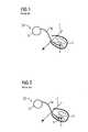
- FIG. 1shows a unipolar pacemaker according to the prior art
- FIG. 2shows a bipolar pacemaker according to the prior art
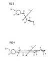
- FIG. 3shows a unipolar pacemaker according to the invention
- FIG. 4shows a bipolar pacemaker according to the invention
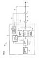
- FIG. 5shows a block diagram of the pacemaker according to FIG. 3
- FIG. 1 and FIG. 2show a greatly simplified unipolar pacemaker 1 a and a bipolar pacemaker 1 b , which each comprise a pacemaker housing 2 and a unipolar pacemaker electrode 3 a and a bipolar pacemaker electrode 3 b .
- the pacemaker electrode 3 a and 3 bis fixed in the ventricle of a heart by means of an electrode tip 4 sad is provided to transmit simulation impulses.
- a number of pacemaker electrodes 3 a and 3 bcan also be provided, which are guided to the atrium and to the ventricle.
- an anode ring 6is arranged at a distance of approximately 2.5 cm from the electrode tip 4 .
- the function of the anodeis assumed in the unipolar system ( FIG. 1 ) by the pacemaker housing 2 .
- An external magnetic field 7is indicated in both systems by a dashed arrow. If this increases to values which are too great, an electrical current can be induced in the pacemaker electrode 3 a , 3 b , said current representing a grave danger for the patient. For this reason patients with pacemaker systems according to FIGS. 1 and 2 cannot be examined using magnetic resonance devices.
- FIGS. 3 and 4show a symbolic representation in each instance of a pacemaker 1 a , 1 b according to the invention in a unipolar ( FIG. 3 ) and a bipolar ( FIG. 4 ) embodiment.
- the unipolar pacemaker electrode 3 a according to FIG. 3is thus equipped with two switches 8
- the bipolar pacemaker electrode 3 b according to FIG. 4is equipped with four switches 8 , generally also referred to as circuit elements.
- the switches 8open once the magnetic field 7 exceeds a preferably adjustable limit value and thus protect the patient from dangerous exposure by means of induced currents.
- FIG. 3shows a symbolic representation in each instance of a pacemaker 1 a , 1 b according to the invention in a unipolar ( FIG. 3 ) and a bipolar ( FIG. 4 ) embodiment.
- the unipolar pacemaker electrode 3 a according to FIG. 3is thus equipped with two switches 8
- the bipolar pacemaker electrode 3 b according to FIG. 4is equipped with four switches 8 , generally also
- an electromagnetis located in the region of the electrode tip, which, in conjunction with an external magnetic field, allows the pacemaker electrode 3 b to be navigated in the body of the patient.
- a magnetic navigation of this typecan be similarly realized with the exemplary embodiment according to FIG. 3 .
- a permanent magnetcon be used in place of the electromagnet 9 .
- FIG. 5shows a schematic representation of the structure of the pacemaker 1 a according to FIG. 3 .
- a control unit 10is located in the pacemaker housing 2 , which interacts with a detection unit 11 , which serves to detect the signals (so-called sensing) outgoing from the heart 5 , and interacts with an impulse generator 12 which generates the impulses to be transmitted to the pacemaker electrode 3 .
- a battery 13is provided for the power supply of the overall pacemaker 1 a.
- the pacemaker housing 2further comprises a telemetry unit 14 , which enables the status of the pacemaker 1 a to be queried, and in particular enables the circuit element 8 to be switched from the outside of the patient.
- the circuit elements 8are connected to a control unit 16 by means of control lines 15 . This comprises an effective link with a current monitoring unit 17 , to which a measuring element 19 is connected via a measuring line, said measuring element detects the induced current in the pacemaker electrode 3 .
- a wireless signal transmissioncan also be provided instead of a wired signal transmission between different components of the pacemaker 1 a .
- the components within the pacemaker housing 2 shown in FIG. 5are similarly also located in the pacemaker 1 b of the exemplary embodiment according to FIG. 4 .
Landscapes
- Health & Medical Sciences (AREA)
- Cardiology (AREA)
- Heart & Thoracic Surgery (AREA)
- Engineering & Computer Science (AREA)
- Biomedical Technology (AREA)
- Nuclear Medicine, Radiotherapy & Molecular Imaging (AREA)
- Radiology & Medical Imaging (AREA)
- Life Sciences & Earth Sciences (AREA)
- Animal Behavior & Ethology (AREA)
- General Health & Medical Sciences (AREA)
- Public Health (AREA)
- Veterinary Medicine (AREA)
- Electrotherapy Devices (AREA)
Abstract
Description
Claims (13)
Applications Claiming Priority (3)
| Application Number | Priority Date | Filing Date | Title |
|---|---|---|---|
| DE102004062399 | 2004-12-23 | ||
| DE102004062399.6 | 2004-12-23 | ||
| DE102004062399ADE102004062399B4 (en) | 2004-12-23 | 2004-12-23 | Implantable pacemaker |
Publications (2)
| Publication Number | Publication Date |
|---|---|
| US20060142813A1 US20060142813A1 (en) | 2006-06-29 |
| US8473052B2true US8473052B2 (en) | 2013-06-25 |
Family
ID=36590491
Family Applications (1)
| Application Number | Title | Priority Date | Filing Date |
|---|---|---|---|
| US11/311,772Expired - Fee RelatedUS8473052B2 (en) | 2004-12-23 | 2005-12-19 | Implantable pacemaker |
Country Status (2)
| Country | Link |
|---|---|
| US (1) | US8473052B2 (en) |
| DE (1) | DE102004062399B4 (en) |
Families Citing this family (3)
| Publication number | Priority date | Publication date | Assignee | Title |
|---|---|---|---|---|
| DE102006015013B4 (en) | 2006-03-31 | 2010-06-02 | Siemens Ag | Implantable pacemaker |
| US8768486B2 (en)* | 2006-12-11 | 2014-07-01 | Medtronic, Inc. | Medical leads with frequency independent magnetic resonance imaging protection |
| US8437863B2 (en) | 2008-12-19 | 2013-05-07 | St. Jude Medical Ab | Electrode lead |
Citations (22)
| Publication number | Priority date | Publication date | Assignee | Title |
|---|---|---|---|---|
| US4399821A (en)* | 1981-02-19 | 1983-08-23 | Bowers David L | Free moving animal physiological monitoring and identification system and method |
| EP0030953B1 (en) | 1979-06-14 | 1984-09-26 | REENSTIERNA, Bertil | Endocardial, implantable lead for pacemaker |
| US4611127A (en)* | 1984-09-20 | 1986-09-09 | Telectronics N.V. | Electronic sensor for static magnetic field |
| US4745923A (en)* | 1985-11-20 | 1988-05-24 | Intermedics, Inc. | Protection apparatus for patient-implantable device |
| US5217010A (en)* | 1991-05-28 | 1993-06-08 | The Johns Hopkins University | Ecg amplifier and cardiac pacemaker for use during magnetic resonance imaging |
| US5476501A (en)* | 1994-05-06 | 1995-12-19 | Medtronic, Inc. | Silicon insulated extendable/retractable screw-in pacing lead with high efficiency torque transfer |
| US5541507A (en)* | 1992-09-29 | 1996-07-30 | Pacesetter Ab | Device for detecting the position of a magnet by analyzing movement of a current-fed coil disposed in the magnetic field of the magnet |
| US5620463A (en)* | 1991-12-20 | 1997-04-15 | Free World Trust | Electrophysiological conditioning system and method |
| US6161040A (en)* | 1999-02-16 | 2000-12-12 | Pacesetter, Inc. | Current limiter for an implantable cardiac device |
| US6209764B1 (en)* | 1997-04-30 | 2001-04-03 | Medtronic, Inc. | Control of externally induced current in implantable medical devices |
| US6330467B1 (en) | 1999-02-04 | 2001-12-11 | Stereotaxis, Inc. | Efficient magnet system for magnetically-assisted surgery |
| US20020019644A1 (en)* | 1999-07-12 | 2002-02-14 | Hastings Roger N. | Magnetically guided atherectomy |
| EP0882469B1 (en) | 1997-06-06 | 2002-09-18 | St. Jude Medical AB | Implantable heart stimulator |
| US20020133211A1 (en)* | 2001-02-20 | 2002-09-19 | Weiner Michael L. | Electromagnetic interference immune tissue invasive system |
| US20030083570A1 (en)* | 2001-10-31 | 2003-05-01 | Cho Yong Kyun | Alternative sensing method for implantable medical device in magnetic resonance imaging device |
| US20030083726A1 (en) | 2001-10-31 | 2003-05-01 | Medtronic, Inc. | Method and apparatus for shunting induced currents in an electrical lead |
| US20030140931A1 (en) | 2002-01-29 | 2003-07-31 | Zeijlemaker Volkert A. | Medical implantable system for reducing magnetic resonance effects |
| US20030176786A1 (en) | 2002-01-29 | 2003-09-18 | Michael Maschke | Catheter with variable magnetic field generator for catheter guidance in a subject |
| US6772001B2 (en) | 2002-01-29 | 2004-08-03 | Siemens Aktiengesellschaft | Medical examination and/or treatment system |
| US20050003268A1 (en)* | 2003-05-16 | 2005-01-06 | Scott Erik R. | Battery housing configuration |
| US20050065587A1 (en)* | 2003-09-24 | 2005-03-24 | Mark Gryzwa | Implantable lead with magnetic jacket |
| US6925328B2 (en)* | 2000-04-20 | 2005-08-02 | Biophan Technologies, Inc. | MRI-compatible implantable device |
- 2004
- 2004-12-23DEDE102004062399Apatent/DE102004062399B4/ennot_activeExpired - Fee Related
- 2005
- 2005-12-19USUS11/311,772patent/US8473052B2/ennot_activeExpired - Fee Related
Patent Citations (22)
| Publication number | Priority date | Publication date | Assignee | Title |
|---|---|---|---|---|
| EP0030953B1 (en) | 1979-06-14 | 1984-09-26 | REENSTIERNA, Bertil | Endocardial, implantable lead for pacemaker |
| US4399821A (en)* | 1981-02-19 | 1983-08-23 | Bowers David L | Free moving animal physiological monitoring and identification system and method |
| US4611127A (en)* | 1984-09-20 | 1986-09-09 | Telectronics N.V. | Electronic sensor for static magnetic field |
| US4745923A (en)* | 1985-11-20 | 1988-05-24 | Intermedics, Inc. | Protection apparatus for patient-implantable device |
| US5217010A (en)* | 1991-05-28 | 1993-06-08 | The Johns Hopkins University | Ecg amplifier and cardiac pacemaker for use during magnetic resonance imaging |
| US5620463A (en)* | 1991-12-20 | 1997-04-15 | Free World Trust | Electrophysiological conditioning system and method |
| US5541507A (en)* | 1992-09-29 | 1996-07-30 | Pacesetter Ab | Device for detecting the position of a magnet by analyzing movement of a current-fed coil disposed in the magnetic field of the magnet |
| US5476501A (en)* | 1994-05-06 | 1995-12-19 | Medtronic, Inc. | Silicon insulated extendable/retractable screw-in pacing lead with high efficiency torque transfer |
| US6209764B1 (en)* | 1997-04-30 | 2001-04-03 | Medtronic, Inc. | Control of externally induced current in implantable medical devices |
| EP0882469B1 (en) | 1997-06-06 | 2002-09-18 | St. Jude Medical AB | Implantable heart stimulator |
| US6330467B1 (en) | 1999-02-04 | 2001-12-11 | Stereotaxis, Inc. | Efficient magnet system for magnetically-assisted surgery |
| US6161040A (en)* | 1999-02-16 | 2000-12-12 | Pacesetter, Inc. | Current limiter for an implantable cardiac device |
| US20020019644A1 (en)* | 1999-07-12 | 2002-02-14 | Hastings Roger N. | Magnetically guided atherectomy |
| US6925328B2 (en)* | 2000-04-20 | 2005-08-02 | Biophan Technologies, Inc. | MRI-compatible implantable device |
| US20020133211A1 (en)* | 2001-02-20 | 2002-09-19 | Weiner Michael L. | Electromagnetic interference immune tissue invasive system |
| US20030083570A1 (en)* | 2001-10-31 | 2003-05-01 | Cho Yong Kyun | Alternative sensing method for implantable medical device in magnetic resonance imaging device |
| US20030083726A1 (en) | 2001-10-31 | 2003-05-01 | Medtronic, Inc. | Method and apparatus for shunting induced currents in an electrical lead |
| US20030140931A1 (en) | 2002-01-29 | 2003-07-31 | Zeijlemaker Volkert A. | Medical implantable system for reducing magnetic resonance effects |
| US20030176786A1 (en) | 2002-01-29 | 2003-09-18 | Michael Maschke | Catheter with variable magnetic field generator for catheter guidance in a subject |
| US6772001B2 (en) | 2002-01-29 | 2004-08-03 | Siemens Aktiengesellschaft | Medical examination and/or treatment system |
| US20050003268A1 (en)* | 2003-05-16 | 2005-01-06 | Scott Erik R. | Battery housing configuration |
| US20050065587A1 (en)* | 2003-09-24 | 2005-03-24 | Mark Gryzwa | Implantable lead with magnetic jacket |
Also Published As
| Publication number | Publication date |
|---|---|
| DE102004062399A1 (en) | 2006-07-06 |
| US20060142813A1 (en) | 2006-06-29 |
| DE102004062399B4 (en) | 2009-02-05 |
Similar Documents
| Publication | Publication Date | Title |
|---|---|---|
| US9849292B2 (en) | MRI compatible implantable medical devices and methods | |
| US5076272A (en) | Autocontrollable pacemaker with alarm | |
| US8032228B2 (en) | Method and apparatus for disconnecting the tip electrode during MRI | |
| US7729770B2 (en) | Isolation circuitry and method for gradient field safety in an implantable medical device | |
| US6795730B2 (en) | MRI-resistant implantable device | |
| US4140131A (en) | Body tissue stimulation apparatus with warning device | |
| US20140039568A1 (en) | Detection of strong static magnetic fields and mri examination safekeeping for an implantable cardiac prosthesis | |
| US12053625B2 (en) | Methods, implantable medical leads, and related systems to monitor and limit temperature changes in proximty to electrodes | |
| US20030204217A1 (en) | MRI-safe cardiac stimulation device | |
| US20100160989A1 (en) | Implantable Cardiac Prosthesis Generator Having Protection From an MRI Examination | |
| US20110245888A1 (en) | Medical device with charge leakage detection | |
| US9278212B2 (en) | Lead for implantable cardiac prosthesis with integrated protection against the effects of MRI fields | |
| US8473052B2 (en) | Implantable pacemaker | |
| Bhachu et al. | Implantable pulse generators (pacemakers) and electrodes: safety in the magnetic resonance imaging scanner environment | |
| US20120245452A1 (en) | Implantable device | |
| US8494646B2 (en) | Implantable device | |
| EP3651848B1 (en) | Methods, implantable medical leads, and related systems to monitor and limit temperature changes in proximity to electrodes | |
| US8649877B2 (en) | Extended noise mode | |
| Trotman | Meeting report: implantable cardiac pacemakers |
Legal Events
| Date | Code | Title | Description |
|---|---|---|---|
| AS | Assignment | Owner name:SIEMENS AKTIENGESELLSCHAFT, GERMANY Free format text:ASSIGNMENT OF ASSIGNORS INTEREST;ASSIGNOR:MASCHKE, MICHAEL;REEL/FRAME:017359/0285 Effective date:20051206 | |
| STCF | Information on status: patent grant | Free format text:PATENTED CASE | |
| AS | Assignment | Owner name:SIEMENS HEALTHCARE GMBH, GERMANY Free format text:ASSIGNMENT OF ASSIGNORS INTEREST;ASSIGNOR:SIEMENS AKTIENGESELLSCHAFT;REEL/FRAME:039271/0561 Effective date:20160610 | |
| FPAY | Fee payment | Year of fee payment:4 | |
| FEPP | Fee payment procedure | Free format text:MAINTENANCE FEE REMINDER MAILED (ORIGINAL EVENT CODE: REM.); ENTITY STATUS OF PATENT OWNER: LARGE ENTITY | |
| LAPS | Lapse for failure to pay maintenance fees | Free format text:PATENT EXPIRED FOR FAILURE TO PAY MAINTENANCE FEES (ORIGINAL EVENT CODE: EXP.); ENTITY STATUS OF PATENT OWNER: LARGE ENTITY | |
| STCH | Information on status: patent discontinuation | Free format text:PATENT EXPIRED DUE TO NONPAYMENT OF MAINTENANCE FEES UNDER 37 CFR 1.362 | |
| FP | Lapsed due to failure to pay maintenance fee | Effective date:20210625 |