US8472119B1 - Image waveguide having a bend - Google Patents
Image waveguide having a bendDownload PDFInfo
- Publication number
- US8472119B1 US8472119B1US13/209,252US201113209252AUS8472119B1US 8472119 B1US8472119 B1US 8472119B1US 201113209252 AUS201113209252 AUS 201113209252AUS 8472119 B1US8472119 B1US 8472119B1
- Authority
- US
- United States
- Prior art keywords
- waveguide
- light
- segment
- region
- bend
- Prior art date
- Legal status (The legal status is an assumption and is not a legal conclusion. Google has not performed a legal analysis and makes no representation as to the accuracy of the status listed.)
- Expired - Fee Related, expires
Links
Images


Classifications
- G—PHYSICS
- G02—OPTICS
- G02B—OPTICAL ELEMENTS, SYSTEMS OR APPARATUS
- G02B5/00—Optical elements other than lenses
- G02B5/30—Polarising elements
- G—PHYSICS
- G02—OPTICS
- G02B—OPTICAL ELEMENTS, SYSTEMS OR APPARATUS
- G02B27/00—Optical systems or apparatus not provided for by any of the groups G02B1/00 - G02B26/00, G02B30/00
- G02B27/01—Head-up displays
- G02B27/017—Head mounted
- G—PHYSICS
- G02—OPTICS
- G02B—OPTICAL ELEMENTS, SYSTEMS OR APPARATUS
- G02B27/00—Optical systems or apparatus not provided for by any of the groups G02B1/00 - G02B26/00, G02B30/00
- G02B27/01—Head-up displays
- G02B27/017—Head mounted
- G02B2027/0178—Eyeglass type
Definitions
- This disclosurerelates generally to the field of optics, and in particular but not exclusively, relates to near-to-eye optical systems.
- a head mounted displayis a display device worn on or about the head.
- HMDsusually incorporate some sort of near-to-eye optical system to display an image within a few centimeters of the human eye.
- Single eye displaysare referred to as monocular HMDs while dual eye displays are referred to as binocular HMDs.
- Some HMDsdisplay only a computer generated image (“CGI”), while other types of HMDs are capable of superimposing CGI over a real-world view.
- CGIcomputer generated image
- the former type of HDMis often referred to as virtual reality while latter type of HMD is often referred to as augmented reality because the viewer's image of the world is augmented with an overlaying CGI, also referred to as a heads-up display (“HUD”).
- HUDheads-up display
- HMDshave numerous practical and leisure applications. Aerospace applications permit a pilot to see vital flight control information without taking their eye off the flight path. Public safety applications include tactical displays of maps and thermal imaging. Other application fields include video games, transportation, and telecommunications. There is certain to be new found practical and leisure applications as the technology evolves; however, many of these applications are limited due to the cost, size, field of view, form factor, and efficiency of conventional optical systems used to implement existing HMDs.
- the image waveguidehas a bend and includes a first segment and a second segment operatively coupled at the bend, the first and second segments each including a pair of reflective surfaces being substantially parallel and opposing each other; an in-coupling region for receiving light into the first segment of the waveguide; an out-coupling region to allow the light to exit the second segment of the waveguide; and a light filtering region disposed near the bend between the first segment of the waveguide and the second segment of the waveguide to selectively filter light transmitted from the first segment of the waveguide to the second segment of the waveguide.
- FIG. 1Aillustrates a first conventional near-to-eye optical system using an input lens and two mirrors in accordance with an embodiment of the disclosure.
- FIG. 1Billustrates a second conventional near-to-eye optical system using angle sensitive dichroic mirrors in accordance with an embodiment of the disclosure.
- FIG. 1Cillustrates a third conventional near-to-eye optical system using holographic diffraction gratings in accordance with an embodiment of the disclosure.
- FIG. 2illustrates a waveguide with a bend in accordance with an embodiment of the disclosure.
- FIG. 3illustrates a waveguide with a bend in accordance with an embodiment of the disclosure.
- FIG. 4illustrates a waveguide with an angle-selective region in accordance with an embodiment of the disclosure.
- FIG. 5illustrates a waveguide with an angle-selective region in accordance with an embodiment of the disclosure.
- FIG. 6A and FIG. 6Billustrate waveguides with an angle-selective region and an anti-reflective region in accordance with embodiments of the disclosure.
- FIG. 7is a top view of a demonstrative near-to-eye imaging system in accordance with an embodiment of the disclosure.
- Embodiments of an apparatus, system and method to utilize a waveguide having a bendare described herein.
- numerous specific detailsare set forth to provide a thorough understanding of the embodiments.
- One skilled in the relevant artwill recognize, however, that the techniques described herein can be practiced without one or more of the specific details, or with other methods, components, materials, etc.
- well-known structures, materials, or operationsare not shown or described in detail to avoid obscuring certain aspects.
- FIG. 1Aillustrates a first conventional near-to-eye optical system 101 using an input lens and two mirrors according to an embodiment of the disclosure.
- An image source 105outputs an image that is reflected by two mirrors 110 and 115 , which form an image near to eye 120 .
- Image source 105is typically mounted above the head or to the side of the head, while mirrors 110 and 115 bend the image around the front of the viewer's face to their eye 120 . Since the human eye is typically incapable of focusing on objects placed within a few centimeters, this system requires a lens 125 interposed between the first mirror 110 and image source 105 .
- Lens 125creates a virtual image that is displaced further back from the eye than the actual location of mirror 115 by positioning image source 105 inside of the focal point ⁇ of lens 125 .
- Optical system 101suffers from a relatively small field of view (e.g., approximately 20 degrees) limited by the extent of mirrors 110 and 115 and the bulkiness of lens 125 .
- the field of viewcan be marginally improved by placing mirrors 110 and 115 within a high index material to compress the angles of incidence, but is still very limited and the thickness of the waveguide rapidly increases to achieve larger fields of view, adversely affecting the form factor of system 101 .
- FIG. 1Billustrates a second conventional near-to-eye optical system 102 using angle sensitive dichroic mirrors according to an embodiment of the disclosure.
- Optical system 102includes a single in-coupling mirror 130 and two out-coupling dichroic mirrors 135 disposed within a waveguide 140 .
- This systemuses collimated input light from virtual images placed at infinity.
- each incident angle of input lightshould correspond to a single output angle of emitted light. Since light can potentially reflect off of output mirrors 135 on either a downward trajectory (ray segments 145 ) or an upward trajectory (ray segments 150 ), each input angle can potentially result in multiple output angles, thereby destroying the output image.
- optical system 102uses angle sensitive dichroic mirrors 135 that pass light with incident sufficiently close to normal while reflecting light having a sufficiently oblique incidence.
- optical system 102still has a non-ideal form factor and the nature of dichroic mirrors 135 that passes some incident angles while reflecting others limits the field of view optical system 102 and the dichroic mirror coating does not provide sharp angular cutoffs, resulting in ghosting effects.
- FIG. 1Cillustrates a third conventional near-to-eye optical system 103 using holographic diffraction gratings.
- Optical system 103is similar to optical system 102 , but uses holographic diffraction gratings 150 in place of mirrors 130 and 135 .
- Diffraction gratings 150are inefficient reflectors, since they only reflect higher order diffractions while passing the first order diffraction, which contains the largest portion of energy in an optical wave front.
- the input and output diffraction gratingsmust be precisely tuned to one another, else the output image will suffer from color separation. Achieving a sufficient match between the input and output gratings 150 requires extreme control over manufacturing tolerances, which is often difficult and costly.
- optical system 103suffers from a limited field of view and a non-ideal form factor.
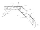
- FIG. 2illustrates a waveguide with a bend in accordance with an embodiment of the disclosure.
- the illustrated embodimentis a cross-sectional view of an image waveguide for generating a near-to-eye image.
- Waveguide 200includes first segment 210 which receives substantially collimated light 220 from light source 280 . Said light is propagated through the waveguide segment 210 via surfaces 211 and 212 , which comprise reflective material and are substantially parallel to one another.
- light 220is guided by total internal reflection (“TIR”).
- TIRtotal internal reflection
- Waveguide 200further includes second segment 250 , which receives light from first segment 210 as light 225 . Said light is propagated through the waveguide segment via surfaces 251 and 252 , which comprise reflective material and are substantially parallel to one another. In one embodiment, light 225 is guided by TIR. In the illustrated embodiment, waveguide 200 includes two planar waveguides that are bonded at bend 230 . In one embodiment, waveguide segments 210 and 250 are each a single piece injection molded waveguide segment.
- Out-coupling region 290may comprise openings, diffraction gratings, non-reflective optically transmissive regions, or any functionally equivalent means to allow light to exit waveguide 200 .
- out-coupling region 290is configured to direct light 225 towards the user's eye 295 along a path substantially normal to surface 251 .
- waveguide segment 210 and waveguide segment 250are angled relative to one another to form a bend angle ⁇ for waveguide 200 .
- ⁇is equal to or greater than 90 degrees.
- waveguide 200includes bend 230 , formed where waveguide section 210 couples to waveguide 250 .
- Surfaces 211 , 212 , 251 and 252form waveguide core 205 , which may comprise air, glass, quartz, acrylic, plastic or any other optically transparent material.
- Embodiments of the inventionsuch as waveguide 200 may be used in a single eye display (i.e., a monocular HMD) or a dual eye display (i.e., a binocular HMDs).
- Waveguide 200may be used to display only a CGI (i.e., a virtual reality (VR) system) wherein at least reflective surface 252 of waveguide segment 250 is fabricated with a non-optically transmissive material—e.g., a reflective metal film, such as, aluminum, nickel, gold, chromium, tin, or otherwise.
- a reflective metal filmsuch as, aluminum, nickel, gold, chromium, tin, or otherwise.
- reflective surfaces of waveguide 200are fabricated using partially reflective layers or a dichroic film, which enables wavelength selectivity for specific transmission and reflection behavior.
- Waveguide 200may also be used in an HMD capable of superimposing CGI over a real-world view (i.e., an augmented reality (AR) system) where the user's image of the world is augmented with an overlaying CGI, also referred to as a heads-up display (HUD).
- HUDheads-up display
- at least both reflective surfaces 251 and 252 of waveguide segment 250are fabricated of a partially transmissive material to permit external ambient light to pass through to eye 295 .
- waveguide 200In one embodiment, light enters waveguide 200 and traverse waveguide segments 210 and 250 at sufficiently oblique angles that it is guided within the waveguide via TIR.
- waveguide 200is fabricated of a polymer material having an index of refraction of approximately 1.5.
- non-optically transmissive material to fabricate waveguide 200it is understood that TIR in not required to guide light within the waveguide.
- a combination of TIR and non-optically transmissive materialmay also be used (e.g., waveguide segment 210 is fabricated from non-optically transmissive material, while waveguide segment 250 is fabricated from optically transmissive material).
- FIG. 3illustrates a waveguide with a bend in accordance with an embodiment of the disclosure.
- the illustrated embodimentis a cross-sectional view of an image waveguide for generating a near-to-eye image. It is understood that forming a waveguide having a bend may cause any light that has some divergence to be transferred between the first and second segments at different angles.
- waveguide 300is shown to include first segment 310 and second segment 350 . Segment 310 includes parallel surfaces 311 and 312 , while segment 350 includes segments 351 and 352 . Segments 311 and 351 form an “inner bend” while segments 312 and 352 form an “outer bend.”
- Light source 380may emit substantially collimated light, with some spatial extent or light divergence present (e.g., due to imperfections in the light source). As shown in the illustration, light source 380 emits light with some divergence—i.e., light 330 and light 320 are emitted from the same point, but light 330 diverges from light 320 (the divergence in this example has been accentuated to illustrate the effect described below). When light is transferred from segment 310 to segment 350 , the last reflection before transfer between the segments is a reflection off either bottom surface 311 or top surface 312 .
- the light reflected from bottom surface 311 (shown as light 320 ) of waveguide segment 310is received by top surface 352 of waveguide segment 350 (shown as light 325 ) at an angle that allows the light to propagate through the rest of the waveguide (e.g., at an angle that enables TIR); however, divergent light 330 may be reflected from top surface 312 of waveguide segment 310 , rather than the bottom surface, just prior to entering the second waveguide section 350 .
- divergent light 330may reflect off of top surface 312 and enter into waveguide segment 350 at a different angle (shown as light 335 ) than light 325 .
- out-coupling region 390is configured to direct light 325 towards the user's eye 395 sufficiently close to normal; however, light 335 exits at a different angle.
- waveguide 300should preserve a one-to-one relation of input light angles to output light angles so that the output light is also substantially collimated and therefore virtually projected at or near infinity.
- light 325 and light 335arrive at the user's eye 395 at different angles and therefore light originating from a common point in image source 380 is delivered to eye 395 with two different angles due to a finite divergence of the cone of light emitted from image source 380 . This may produce the undesired effect of dual or blurred images for the user.
- FIG. 4illustrates a waveguide with an angle-selective region in accordance with an embodiment of the disclosure.
- the illustrated embodimentis a cross-sectional view of an image waveguide for generating a near-to-eye image.
- waveguide 400receives light from light source 480 , and includes first segment 410 having parallel, reflective surfaces 411 and 412 , and second segment 450 having parallel, reflective surfaces 451 and 452 .
- angle selective region 460is formed between first and second segments 410 and 450 and selectively filters light transmitted from the first segment to the second segment.
- Angle selective region 460may be an angle sensitive dichroic mirror that passes light in a first angle range while reflecting light in a second angle range.
- light 420reflects off of surface 411 and enters the bend at an allowable angle (e.g., sufficiently close to normal), and this light is permitted to pass through region 460 , and into waveguide segment 450 as light 425 .
- Divergent light 430reflects off of surface 412 enters the bend at a filtered angle (e.g., having a sufficiently oblique incidence), and region 460 is configured to reject this particular angle of light. Thus, light 430 is reflected back into region 410 .
- waveguide 400rejects divergent light 430 , thereby preserving a one-to-one relation of input light angles to output light angles so that only substantially collimated output light arrives at out-coupling region 490 and is received by eye 495 of a user. It is to be understood that while in this embodiment, light reflected off the “outer bend” of waveguide 400 is rejected, in other embodiments light reflected off of an “inner bend” of a waveguide may be rejected.
- FIG. 5illustrates a waveguide with an angle-selective region in accordance with an embodiment of the disclosure.
- the illustrated embodimentis a cross-sectional view of an image waveguide for generating a near-to-eye image.
- waveguide 500receives substantially collimated light from light source 580 and includes first segment 510 having parallel, reflective surfaces 511 and 512 , and second segment 550 having parallel, reflective surfaces 551 and 552 .
- angle selective region 560is formed between first and second segments 510 and 550 and selectively filters light transmitted from the first segment to the second segment.
- Angle selective region 560is formed by surfaces 513 and 553 , which are parallel to each other.
- region 560comprises an air gap between surfaces 513 and 553 .
- light 520enters the bend reflected off of bottom surface 511 of waveguide segment 510 , and region 560 is configured such that this light enters segment 550 sufficiently close enough to normal, and proceeds to propagate into segment 550 as light 525 .
- divergent light 530enters the bend as an immediate reflection off of top surface 512 , and region 560 is configured to reject this particular angle of light; specifically, light 530 cannot pass through surface 513 due to its large angle of incidence (e.g., light 530 is not close enough to normal) and is therefore rejected by TIR at surface 513 .
- light 530reflects back into waveguide segment 510 .
- region 560eliminates one of the angles of light produced at the bend of the waveguide, thereby preserving a one-to-one relation of input light angles to output light angles so that collimated output light arrives at out-coupling region 590 and is received by eye 595 of a user.
- FIG. 6A and FIG. 6Billustrate waveguides with an angle-selective region and an anti-reflective region in accordance with embodiments of the disclosure.
- the illustrated embodiment of FIG. 6Ais a cross-sectional view of a portion of an image waveguide for generating a near-to-eye image.
- waveguide 600includes first segment 610 having parallel, reflective surfaces 611 and 612 , and second segment 650 having parallel, reflective surfaces 651 and 652 .
- angle selective region 690is formed between first and second segments 610 and 650 to selectively filter light transmitted from the first segment to the second segment.
- region 690is configured to reject divergent light reflected off of top surface 612 of waveguide segment 610 (shown as light 630 ), while allowing light reflected off of bottom surface 611 (shown as light 620 ) to pass through the region and into waveguide segment 650 (shown as light 625 ).
- region 690may not successfully reject all divergent light reflected from top surface 612 .
- imperfections in the surface of region 690may exist that allow some light to pass through the region and into waveguide segment 650 that would otherwise be rejected.
- Embodiments of the inventionmay utilize anti-reflective regions disposed near region 690 to reduce the possibility of light erroneously passing through the region.
- reflective surface 612includes anti-reflective region 691 disposed near angle selective region 690 to emit light 635 from the waveguide as this light should be rejected by the region.
- reflective surface 651includes anti-reflective region 692 disposed near angle selective region 690 to emit light 636 , reflected from top surface 612 , from the waveguide as this light should have been rejected by the region.
- anti-reflective region 692is provided as an additional backup to encourage early emission of light 636 that happens to make it through angle selective region 690 by inhibiting TIR in the localized region of anti-reflection region 692 .
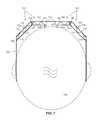
- FIG. 7is a top view of a demonstrative near-to-eye imaging system in accordance with an embodiment of the disclosure.
- the illustrated embodiment of imaging system 700includes two image waveguides 701 and 702 , frame 705 including a nose assembly, a left ear assembly, and a right ear assembly, and two image sources 710 and 715 .
- image waveguides 701 and 702are secured into an eye glass arrangement that can be worn on head 799 of a user.
- the left and right ear assembliesrest over the user's ears while the nose assembly rests over the user's nose.
- the frame assemblyis shaped and sized to position out-coupling regions 706 and 707 of each image waveguide in front of a corresponding eye of the user with the emission surfaces facing the eyes.
- Out-coupling regions 706 and 707may comprise openings, diffraction gratings, non-reflective optically transmissive regions, or any functionally equivalent means to allow light to exit waveguide segments 732 and 782 , respectively.
- Image sources 710 and 715are generated by image sources 710 and 715 , respectively.
- Image sources 710 and 715may be implemented using liquid crystal on silicon (“LCoS”) displays, back-lit LCDs, organic LED displays, quantum dot array displays, or otherwise.
- image sources 710 and 715generate substantially collimated light.
- other display technologymay be used.
- the CGI output by image sources 710 and 715is launched into their respective image waveguides, 701 and 702 .
- Each of said waveguideshas a bend.
- waveguide 701includes a bend formed by segment 720 (having parallel surfaces 721 and 722 ) and segment 730 (having parallel surfaces 731 and 732 ).
- Light filtering region 740selectively transfers CGI light of image source 710 from segment 720 (shown as light 760 ) to segment 730 (shown as light 765 ).
- Waveguide 702includes a bend formed by segment 770 (having parallel surfaces 771 and 772 ) and segment 780 (having parallel surfaces 781 and 782 ).
- Light filtering region 790will selectively transfer CGI light of image source 715 from segment 770 (shown as light 765 ) to segment 780 (shown as light 766 ).
- the angle sensitive filtering regionsare provided at the bends to selectively filter the CGI light, since even substantially collimated light has some divergence, which can distort the image at the bends.
- Waveguides 701 and 702have the above described bend to improve the form factor of imaging system 700 , while preserving a one-to-one relation of input light angles to output light angles.
Landscapes
- Physics & Mathematics (AREA)
- General Physics & Mathematics (AREA)
- Optics & Photonics (AREA)
Abstract
Description
Claims (23)
Priority Applications (1)
| Application Number | Priority Date | Filing Date | Title |
|---|---|---|---|
| US13/209,252US8472119B1 (en) | 2011-08-12 | 2011-08-12 | Image waveguide having a bend |
Applications Claiming Priority (1)
| Application Number | Priority Date | Filing Date | Title |
|---|---|---|---|
| US13/209,252US8472119B1 (en) | 2011-08-12 | 2011-08-12 | Image waveguide having a bend |
Publications (1)
| Publication Number | Publication Date |
|---|---|
| US8472119B1true US8472119B1 (en) | 2013-06-25 |
Family
ID=48627699
Family Applications (1)
| Application Number | Title | Priority Date | Filing Date |
|---|---|---|---|
| US13/209,252Expired - Fee RelatedUS8472119B1 (en) | 2011-08-12 | 2011-08-12 | Image waveguide having a bend |
Country Status (1)
| Country | Link |
|---|---|
| US (1) | US8472119B1 (en) |
Cited By (124)
| Publication number | Priority date | Publication date | Assignee | Title |
|---|---|---|---|---|
| US20140146515A1 (en)* | 2012-11-26 | 2014-05-29 | Yazaki Corporation | Pointer structure |
| JP2015125222A (en)* | 2013-12-26 | 2015-07-06 | セイコーエプソン株式会社 | Virtual image display device |
| US9223138B2 (en) | 2011-12-23 | 2015-12-29 | Microsoft Technology Licensing, Llc | Pixel opacity for augmented reality |
| US9244281B1 (en) | 2013-09-26 | 2016-01-26 | Rockwell Collins, Inc. | Display system and method using a detached combiner |
| US9244280B1 (en) | 2014-03-25 | 2016-01-26 | Rockwell Collins, Inc. | Near eye display system and method for display enhancement or redundancy |
| US9297996B2 (en) | 2012-02-15 | 2016-03-29 | Microsoft Technology Licensing, Llc | Laser illumination scanning |
| US9304235B2 (en) | 2014-07-30 | 2016-04-05 | Microsoft Technology Licensing, Llc | Microfabrication |
| US9341846B2 (en) | 2012-04-25 | 2016-05-17 | Rockwell Collins Inc. | Holographic wide angle display |
| US9368546B2 (en) | 2012-02-15 | 2016-06-14 | Microsoft Technology Licensing, Llc | Imaging structure with embedded light sources |
| US9366864B1 (en) | 2011-09-30 | 2016-06-14 | Rockwell Collins, Inc. | System for and method of displaying information without need for a combiner alignment detector |
| US9372347B1 (en) | 2015-02-09 | 2016-06-21 | Microsoft Technology Licensing, Llc | Display system |
| US9423360B1 (en) | 2015-02-09 | 2016-08-23 | Microsoft Technology Licensing, Llc | Optical components |
| US9429692B1 (en) | 2015-02-09 | 2016-08-30 | Microsoft Technology Licensing, Llc | Optical components |
| CN106019586A (en)* | 2016-06-02 | 2016-10-12 | 上海理鑫光学科技有限公司 | Double optical waveguide sheet-type augment reality eyeglass |
| US9507150B1 (en)* | 2011-09-30 | 2016-11-29 | Rockwell Collins, Inc. | Head up display (HUD) using a bent waveguide assembly |
| US9513480B2 (en) | 2015-02-09 | 2016-12-06 | Microsoft Technology Licensing, Llc | Waveguide |
| US9519089B1 (en) | 2014-01-30 | 2016-12-13 | Rockwell Collins, Inc. | High performance volume phase gratings |
| US9523852B1 (en) | 2012-03-28 | 2016-12-20 | Rockwell Collins, Inc. | Micro collimator system and method for a head up display (HUD) |
| US9535253B2 (en) | 2015-02-09 | 2017-01-03 | Microsoft Technology Licensing, Llc | Display system |
| US9578318B2 (en) | 2012-03-14 | 2017-02-21 | Microsoft Technology Licensing, Llc | Imaging structure emitter calibration |
| US9581820B2 (en) | 2012-06-04 | 2017-02-28 | Microsoft Technology Licensing, Llc | Multiple waveguide imaging structure |
| US9674413B1 (en) | 2013-04-17 | 2017-06-06 | Rockwell Collins, Inc. | Vision system and method having improved performance and solar mitigation |
| US9678542B2 (en) | 2012-03-02 | 2017-06-13 | Microsoft Technology Licensing, Llc | Multiple position input device cover |
| US9715110B1 (en) | 2014-09-25 | 2017-07-25 | Rockwell Collins, Inc. | Automotive head up display (HUD) |
| US9715067B1 (en) | 2011-09-30 | 2017-07-25 | Rockwell Collins, Inc. | Ultra-compact HUD utilizing waveguide pupil expander with surface relief gratings in high refractive index materials |
| US9717981B2 (en) | 2012-04-05 | 2017-08-01 | Microsoft Technology Licensing, Llc | Augmented reality and physical games |
| US9726887B2 (en) | 2012-02-15 | 2017-08-08 | Microsoft Technology Licensing, Llc | Imaging structure color conversion |
| US9779643B2 (en) | 2012-02-15 | 2017-10-03 | Microsoft Technology Licensing, Llc | Imaging structure emitter configurations |
| US9787576B2 (en) | 2014-07-31 | 2017-10-10 | Microsoft Technology Licensing, Llc | Propagating routing awareness for autonomous networks |
| US9827209B2 (en) | 2015-02-09 | 2017-11-28 | Microsoft Technology Licensing, Llc | Display system |
| US9904327B2 (en) | 2012-03-02 | 2018-02-27 | Microsoft Technology Licensing, Llc | Flexible hinge and removable attachment |
| US9933684B2 (en) | 2012-11-16 | 2018-04-03 | Rockwell Collins, Inc. | Transparent waveguide display providing upper and lower fields of view having a specific light output aperture configuration |
| US10018844B2 (en) | 2015-02-09 | 2018-07-10 | Microsoft Technology Licensing, Llc | Wearable image display system |
| US20180231783A1 (en)* | 2017-02-16 | 2018-08-16 | Coretronic Corporation | Optical waveguide element and display device |
| US10088675B1 (en) | 2015-05-18 | 2018-10-02 | Rockwell Collins, Inc. | Turning light pipe for a pupil expansion system and method |
| US10108010B2 (en) | 2015-06-29 | 2018-10-23 | Rockwell Collins, Inc. | System for and method of integrating head up displays and head down displays |
| US10126552B2 (en) | 2015-05-18 | 2018-11-13 | Rockwell Collins, Inc. | Micro collimator system and method for a head up display (HUD) |
| US10156681B2 (en) | 2015-02-12 | 2018-12-18 | Digilens Inc. | Waveguide grating device |
| US10192358B2 (en) | 2012-12-20 | 2019-01-29 | Microsoft Technology Licensing, Llc | Auto-stereoscopic augmented reality display |
| US10191515B2 (en) | 2012-03-28 | 2019-01-29 | Microsoft Technology Licensing, Llc | Mobile device light guide display |
| US10241330B2 (en) | 2014-09-19 | 2019-03-26 | Digilens, Inc. | Method and apparatus for generating input images for holographic waveguide displays |
| US10247943B1 (en) | 2015-05-18 | 2019-04-02 | Rockwell Collins, Inc. | Head up display (HUD) using a light pipe |
| US10254942B2 (en) | 2014-07-31 | 2019-04-09 | Microsoft Technology Licensing, Llc | Adaptive sizing and positioning of application windows |
| WO2019068304A1 (en) | 2017-10-02 | 2019-04-11 | CSEM Centre Suisse d'Electronique et de Microtechnique SA - Recherche et Développement | Resonant waveguide grating and applications thereof |
| US10295824B2 (en) | 2017-01-26 | 2019-05-21 | Rockwell Collins, Inc. | Head up display with an angled light pipe |
| US10310268B2 (en) | 2016-12-06 | 2019-06-04 | Microsoft Technology Licensing, Llc | Waveguides with peripheral side geometries to recycle light |
| US10317677B2 (en) | 2015-02-09 | 2019-06-11 | Microsoft Technology Licensing, Llc | Display system |
| US10324733B2 (en) | 2014-07-30 | 2019-06-18 | Microsoft Technology Licensing, Llc | Shutdown notifications |
| US10353202B2 (en)* | 2016-06-09 | 2019-07-16 | Microsoft Technology Licensing, Llc | Wrapped waveguide with large field of view |
| US10359736B2 (en) | 2014-08-08 | 2019-07-23 | Digilens Inc. | Method for holographic mastering and replication |
| US10388073B2 (en) | 2012-03-28 | 2019-08-20 | Microsoft Technology Licensing, Llc | Augmented reality light guide display |
| US10502876B2 (en) | 2012-05-22 | 2019-12-10 | Microsoft Technology Licensing, Llc | Waveguide optics focus elements |
| US10509241B1 (en) | 2009-09-30 | 2019-12-17 | Rockwell Collins, Inc. | Optical displays |
| US10545346B2 (en) | 2017-01-05 | 2020-01-28 | Digilens Inc. | Wearable heads up displays |
| US10558044B2 (en) | 2016-03-30 | 2020-02-11 | Coretronic Corporation | Optical waveguide device and head-mounted display apparatus using the same |
| US10592080B2 (en) | 2014-07-31 | 2020-03-17 | Microsoft Technology Licensing, Llc | Assisted presentation of application windows |
| US10598932B1 (en) | 2016-01-06 | 2020-03-24 | Rockwell Collins, Inc. | Head up display for integrating views of conformally mapped symbols and a fixed image source |
| US10642058B2 (en) | 2011-08-24 | 2020-05-05 | Digilens Inc. | Wearable data display |
| US10670876B2 (en) | 2011-08-24 | 2020-06-02 | Digilens Inc. | Waveguide laser illuminator incorporating a despeckler |
| US10678743B2 (en) | 2012-05-14 | 2020-06-09 | Microsoft Technology Licensing, Llc | System and method for accessory device architecture that passes via intermediate processor a descriptor when processing in a low power state |
| US10678412B2 (en) | 2014-07-31 | 2020-06-09 | Microsoft Technology Licensing, Llc | Dynamic joint dividers for application windows |
| US10678053B2 (en) | 2009-04-27 | 2020-06-09 | Digilens Inc. | Diffractive projection apparatus |
| US10690916B2 (en) | 2015-10-05 | 2020-06-23 | Digilens Inc. | Apparatus for providing waveguide displays with two-dimensional pupil expansion |
| US10725312B2 (en) | 2007-07-26 | 2020-07-28 | Digilens Inc. | Laser illumination device |
| US10732569B2 (en) | 2018-01-08 | 2020-08-04 | Digilens Inc. | Systems and methods for high-throughput recording of holographic gratings in waveguide cells |
| US10732407B1 (en) | 2014-01-10 | 2020-08-04 | Rockwell Collins, Inc. | Near eye head up display system and method with fixed combiner |
| US10747982B2 (en) | 2013-07-31 | 2020-08-18 | Digilens Inc. | Method and apparatus for contact image sensing |
| US10795160B1 (en) | 2014-09-25 | 2020-10-06 | Rockwell Collins, Inc. | Systems for and methods of using fold gratings for dual axis expansion |
| US10859768B2 (en) | 2016-03-24 | 2020-12-08 | Digilens Inc. | Method and apparatus for providing a polarization selective holographic waveguide device |
| US10866419B2 (en) | 2016-02-09 | 2020-12-15 | CSEM Centre Suisse d'Electronique et de Microtechnique SA—Recherche et Développement | Optical combiner and applications thereof |
| US10890707B2 (en) | 2016-04-11 | 2021-01-12 | Digilens Inc. | Holographic waveguide apparatus for structured light projection |
| WO2021010603A1 (en)* | 2019-07-12 | 2021-01-21 | 삼성전자주식회사 | Near-eye display device, augmented reality glasses including same, and operating method therefor |
| US10914950B2 (en) | 2018-01-08 | 2021-02-09 | Digilens Inc. | Waveguide architectures and related methods of manufacturing |
| US10942430B2 (en) | 2017-10-16 | 2021-03-09 | Digilens Inc. | Systems and methods for multiplying the image resolution of a pixelated display |
| JP2021073498A (en)* | 2016-11-08 | 2021-05-13 | ルムス エルティーディー. | Light guide device with optical blocking end, and manufacturing method of the same |
| US11068049B2 (en) | 2012-03-23 | 2021-07-20 | Microsoft Technology Licensing, Llc | Light guide display and field of view |
| US11086216B2 (en) | 2015-02-09 | 2021-08-10 | Microsoft Technology Licensing, Llc | Generating electronic components |
| US20210382309A1 (en)* | 2020-06-03 | 2021-12-09 | Hitachi-Lg Data Storage, Inc. | Image display device |
| US20210389592A1 (en)* | 2016-03-18 | 2021-12-16 | tooz technologies GmbH | Eyeglass lens for an optical imaging element, and augmented reality glasses |
| US11256155B2 (en) | 2012-01-06 | 2022-02-22 | Digilens Inc. | Contact image sensor using switchable Bragg gratings |
| US11300795B1 (en) | 2009-09-30 | 2022-04-12 | Digilens Inc. | Systems for and methods of using fold gratings coordinated with output couplers for dual axis expansion |
| US11307432B2 (en) | 2014-08-08 | 2022-04-19 | Digilens Inc. | Waveguide laser illuminator incorporating a Despeckler |
| US11314084B1 (en) | 2011-09-30 | 2022-04-26 | Rockwell Collins, Inc. | Waveguide combiner system and method with less susceptibility to glare |
| US11320571B2 (en) | 2012-11-16 | 2022-05-03 | Rockwell Collins, Inc. | Transparent waveguide display providing upper and lower fields of view with uniform light extraction |
| US11333891B2 (en) | 2014-01-09 | 2022-05-17 | Samsung Electronics Co., Ltd. | Wearable display apparatus having a light guide element that guides light from a display element and light from an outside |
| US11366316B2 (en) | 2015-05-18 | 2022-06-21 | Rockwell Collins, Inc. | Head up display (HUD) using a light pipe |
| US11372257B2 (en) | 2018-08-08 | 2022-06-28 | Samsung Electronics Co., Ltd. | See-through display device |
| US11378732B2 (en) | 2019-03-12 | 2022-07-05 | DigLens Inc. | Holographic waveguide backlight and related methods of manufacturing |
| US11402801B2 (en) | 2018-07-25 | 2022-08-02 | Digilens Inc. | Systems and methods for fabricating a multilayer optical structure |
| US11415812B2 (en) | 2018-06-26 | 2022-08-16 | Lumus Ltd. | Compact collimating optical device and system |
| US11442222B2 (en) | 2019-08-29 | 2022-09-13 | Digilens Inc. | Evacuated gratings and methods of manufacturing |
| US11487131B2 (en) | 2011-04-07 | 2022-11-01 | Digilens Inc. | Laser despeckler based on angular diversity |
| US11513350B2 (en) | 2016-12-02 | 2022-11-29 | Digilens Inc. | Waveguide device with uniform output illumination |
| US11523092B2 (en) | 2019-12-08 | 2022-12-06 | Lumus Ltd. | Optical systems with compact image projector |
| US11531201B2 (en) | 2015-02-19 | 2022-12-20 | Lumus Ltd. | Compact head-mounted display system having uniform image |
| US11543594B2 (en) | 2019-02-15 | 2023-01-03 | Digilens Inc. | Methods and apparatuses for providing a holographic waveguide display using integrated gratings |
| US11543661B2 (en) | 2014-11-11 | 2023-01-03 | Lumus Ltd. | Compact head-mounted display system protected by a hyperfine structure |
| US11561435B2 (en) | 2017-07-19 | 2023-01-24 | Lumus Ltd. | LCOS illumination via LOE |
| US11561335B2 (en) | 2019-12-05 | 2023-01-24 | Lumus Ltd. | Light-guide optical element employing complementary coated partial reflectors, and light-guide optical element having reduced light scattering |
| US11567316B2 (en)* | 2016-10-09 | 2023-01-31 | Lumus Ltd. | Aperture multiplier with depolarizer |
| US11681143B2 (en) | 2019-07-29 | 2023-06-20 | Digilens Inc. | Methods and apparatus for multiplying the image resolution and field-of-view of a pixelated display |
| US11719938B2 (en) | 2005-11-08 | 2023-08-08 | Lumus Ltd. | Polarizing optical system |
| US11726332B2 (en) | 2009-04-27 | 2023-08-15 | Digilens Inc. | Diffractive projection apparatus |
| US11726329B2 (en) | 2015-01-12 | 2023-08-15 | Digilens Inc. | Environmentally isolated waveguide display |
| US11747568B2 (en) | 2019-06-07 | 2023-09-05 | Digilens Inc. | Waveguides incorporating transmissive and reflective gratings and related methods of manufacturing |
| US11747537B2 (en) | 2017-02-22 | 2023-09-05 | Lumus Ltd. | Light guide optical assembly |
| US11849262B2 (en) | 2019-03-12 | 2023-12-19 | Lumus Ltd. | Image projector |
| US11886008B2 (en) | 2021-08-23 | 2024-01-30 | Lumus Ltd. | Methods of fabrication of compound light-guide optical elements having embedded coupling-in reflectors |
| US11914187B2 (en) | 2019-07-04 | 2024-02-27 | Lumus Ltd. | Image waveguide with symmetric beam multiplication |
| US11940625B2 (en) | 2018-11-08 | 2024-03-26 | Lumus Ltd. | Light-guide display with reflector |
| US12092914B2 (en) | 2018-01-08 | 2024-09-17 | Digilens Inc. | Systems and methods for manufacturing waveguide cells |
| US12099214B2 (en) | 2018-08-26 | 2024-09-24 | Lumus Ltd. | Near-eye displays with scenery reflection suppression |
| US12111479B2 (en) | 2019-09-16 | 2024-10-08 | Lumus Ltd. | Image display system with beam multiplication |
| US12124037B2 (en) | 2020-05-24 | 2024-10-22 | Lumus Ltd. | Compound light-guide optical elements |
| US12124050B2 (en) | 2019-02-28 | 2024-10-22 | Lumus Ltd. | Compact collimated image projector |
| US12135445B2 (en) | 2019-04-15 | 2024-11-05 | Lumus Ltd. | Method of fabricating a light-guide optical element |
| US12140764B2 (en) | 2019-02-15 | 2024-11-12 | Digilens Inc. | Wide angle waveguide display |
| US12152994B2 (en) | 2020-04-30 | 2024-11-26 | Lumus Ltd. | Optical sample characterization |
| US12158612B2 (en) | 2021-03-05 | 2024-12-03 | Digilens Inc. | Evacuated periodic structures and methods of manufacturing |
| US12210153B2 (en) | 2019-01-14 | 2025-01-28 | Digilens Inc. | Holographic waveguide display with light control layer |
| US12306585B2 (en) | 2018-01-08 | 2025-05-20 | Digilens Inc. | Methods for fabricating optical waveguides |
| US12372799B2 (en) | 2020-05-12 | 2025-07-29 | Lumus Ltd. | Rotatable lightpipe |
| US12397477B2 (en) | 2019-02-05 | 2025-08-26 | Digilens Inc. | Methods for compensating for optical surface nonuniformity |
| US12399326B2 (en) | 2021-01-07 | 2025-08-26 | Digilens Inc. | Grating structures for color waveguides |
Citations (48)
| Publication number | Priority date | Publication date | Assignee | Title |
|---|---|---|---|---|
| US4711512A (en) | 1985-07-12 | 1987-12-08 | Environmental Research Institute Of Michigan | Compact head-up display |
| US5076664A (en) | 1989-05-23 | 1991-12-31 | Thomson-Csf | Optical device enabling the introduction of a collimated image in an observer's field of vision |
| US5093567A (en) | 1989-07-14 | 1992-03-03 | Gec-Marconi Limited | Helmet systems with eyepiece and eye position sensing means |
| GB2272980A (en) | 1992-11-26 | 1994-06-01 | Electro Optics Ind Ltd | Optical beam splitting lens |
| WO1996005533A1 (en) | 1994-08-10 | 1996-02-22 | Lawrence Vandewalle | Method and apparatus for direct retinal projection |
| US5539422A (en) | 1993-04-12 | 1996-07-23 | Virtual Vision, Inc. | Head mounted display system |
| US5696521A (en) | 1994-06-22 | 1997-12-09 | Astounding Technologies (M) Sdn. Bhd. | Video headset |
| US5715337A (en) | 1996-09-19 | 1998-02-03 | The Mirco Optical Corporation | Compact display system |
| US5771124A (en) | 1996-07-02 | 1998-06-23 | Siliscape | Compact display system with two stage magnification and immersed beam splitter |
| US5815126A (en) | 1993-10-22 | 1998-09-29 | Kopin Corporation | Monocular portable communication and display system |
| US5844530A (en) | 1994-12-09 | 1998-12-01 | Kabushiki Kaisha Sega Enterprises | Head mounted display, and head mounted video display system |
| US5886822A (en) | 1996-10-08 | 1999-03-23 | The Microoptical Corporation | Image combining system for eyeglasses and face masks |
| US5896232A (en) | 1997-08-07 | 1999-04-20 | International Business Machines Corporation | Highly efficient and compact frontlighting for polarization-based reflection light valves |
| US5943171A (en) | 1998-06-03 | 1999-08-24 | International Business Machines Corporation | Head mounted displays utilizing reflection light valves |
| US5949583A (en) | 1992-02-07 | 1999-09-07 | I-O Display Systems Llc | Head-mounted display with image generator, fold mirror and mirror for transmission to the eye position of the user |
| US6023372A (en) | 1997-10-30 | 2000-02-08 | The Microoptical Corporation | Light weight, compact remountable electronic display device for eyeglasses or other head-borne eyewear frames |
| US6091546A (en) | 1997-10-30 | 2000-07-18 | The Microoptical Corporation | Eyeglass interface system |
| US6172657B1 (en) | 1996-02-26 | 2001-01-09 | Seiko Epson Corporation | Body mount-type information display apparatus and display method using the same |
| US6201629B1 (en) | 1997-08-27 | 2001-03-13 | Microoptical Corporation | Torsional micro-mechanical mirror system |
| US6204974B1 (en) | 1996-10-08 | 2001-03-20 | The Microoptical Corporation | Compact image display system for eyeglasses or other head-borne frames |
| US6222677B1 (en) | 1999-04-12 | 2001-04-24 | International Business Machines Corporation | Compact optical system for use in virtual display applications |
| US6353503B1 (en) | 1999-06-21 | 2002-03-05 | The Micropitical Corporation | Eyeglass display lens system employing off-axis optical design |
| US20030090439A1 (en) | 2001-09-07 | 2003-05-15 | Spitzer Mark B. | Light weight, compact, remountable face-supported electronic display |
| US6618099B1 (en) | 1999-06-21 | 2003-09-09 | The Microoptical Corporation | Display device with eyepiece assembly and display on opto-mechanical support |
| US6690516B2 (en) | 2000-01-31 | 2004-02-10 | Fujitsu Limited | Head mount type display device |
| US6701038B2 (en) | 2001-03-05 | 2004-03-02 | The Microoptical Corporation | Micro-electromechanical optical switch assembly for optical data networks |
| US6724354B1 (en) | 1999-06-21 | 2004-04-20 | The Microoptical Corporation | Illumination systems for eyeglass and facemask display systems |
| US6738535B2 (en) | 2001-01-31 | 2004-05-18 | International Business Machines Corporation | Head-mounted display content transformer |
| US6747611B1 (en) | 2000-07-27 | 2004-06-08 | International Business Machines Corporation | Compact optical system and packaging for head mounted display |
| US6829095B2 (en) | 2000-06-05 | 2004-12-07 | Lumus, Ltd. | Substrate-guided optical beam expander |
| US6879443B2 (en) | 2003-04-25 | 2005-04-12 | The Microoptical Corporation | Binocular viewing system |
| US20060192307A1 (en) | 2005-02-25 | 2006-08-31 | Eugene Giller | Method for producing high quality optical parts by casting |
| US20060192306A1 (en) | 2005-02-25 | 2006-08-31 | The Microoptical Corporation | Manufacturing methods for embedded optical system |
| US7158096B1 (en) | 1999-06-21 | 2007-01-02 | The Microoptical Corporation | Compact, head-mountable display device with suspended eyepiece assembly |
| US7242527B2 (en) | 2005-03-22 | 2007-07-10 | The Microoptical Corporation | Optical system using total internal reflection images |
| US7391573B2 (en) | 2003-09-10 | 2008-06-24 | Lumus Ltd. | Substrate-guided optical devices |
| US20080219025A1 (en) | 2007-03-07 | 2008-09-11 | Spitzer Mark B | Bi-directional backlight assembly |
| US7457040B2 (en) | 2002-03-21 | 2008-11-25 | Lumus Ltd. | Light guide optical device |
| US20090122414A1 (en) | 2005-02-10 | 2009-05-14 | Lumus Ltd. | Substrate-Guided Optical Device Utilzing Thin Transparent Layer |
| US7577326B2 (en) | 2004-08-05 | 2009-08-18 | Lumus Ltd. | Optical device for light coupling |
| US7643214B2 (en) | 2004-06-17 | 2010-01-05 | Lumus Ltd. | Substrate-guided optical device with wide aperture |
| US7663805B2 (en) | 2007-10-09 | 2010-02-16 | Myvu Corporation | Eyewear display and media device interconnection system |
| US20100046070A1 (en) | 2008-08-21 | 2010-02-25 | Sony Corporation | Head-mounted display |
| US20100103078A1 (en) | 2008-10-23 | 2010-04-29 | Sony Corporation | Head-mounted display apparatus |
| US20100149073A1 (en) | 2008-11-02 | 2010-06-17 | David Chaum | Near to Eye Display System and Appliance |
| US20100278480A1 (en) | 2009-04-21 | 2010-11-04 | Vasylyev Sergiy V | Light collection and illumination systems employing planar waveguide |
| US7900068B2 (en) | 2006-09-14 | 2011-03-01 | Hon Hai Precision Industry Co., Ltd. | Mobile multi-media interface and power pack for portable entertainment devices |
| US20110213664A1 (en) | 2010-02-28 | 2011-09-01 | Osterhout Group, Inc. | Local advertising content on an interactive head-mounted eyepiece |
- 2011
- 2011-08-12USUS13/209,252patent/US8472119B1/ennot_activeExpired - Fee Related
Patent Citations (61)
| Publication number | Priority date | Publication date | Assignee | Title |
|---|---|---|---|---|
| US4711512A (en) | 1985-07-12 | 1987-12-08 | Environmental Research Institute Of Michigan | Compact head-up display |
| US5076664A (en) | 1989-05-23 | 1991-12-31 | Thomson-Csf | Optical device enabling the introduction of a collimated image in an observer's field of vision |
| US5093567A (en) | 1989-07-14 | 1992-03-03 | Gec-Marconi Limited | Helmet systems with eyepiece and eye position sensing means |
| US5949583A (en) | 1992-02-07 | 1999-09-07 | I-O Display Systems Llc | Head-mounted display with image generator, fold mirror and mirror for transmission to the eye position of the user |
| GB2272980A (en) | 1992-11-26 | 1994-06-01 | Electro Optics Ind Ltd | Optical beam splitting lens |
| US5539422A (en) | 1993-04-12 | 1996-07-23 | Virtual Vision, Inc. | Head mounted display system |
| US5815126A (en) | 1993-10-22 | 1998-09-29 | Kopin Corporation | Monocular portable communication and display system |
| US5696521A (en) | 1994-06-22 | 1997-12-09 | Astounding Technologies (M) Sdn. Bhd. | Video headset |
| WO1996005533A1 (en) | 1994-08-10 | 1996-02-22 | Lawrence Vandewalle | Method and apparatus for direct retinal projection |
| US5844530A (en) | 1994-12-09 | 1998-12-01 | Kabushiki Kaisha Sega Enterprises | Head mounted display, and head mounted video display system |
| US6172657B1 (en) | 1996-02-26 | 2001-01-09 | Seiko Epson Corporation | Body mount-type information display apparatus and display method using the same |
| US5771124A (en) | 1996-07-02 | 1998-06-23 | Siliscape | Compact display system with two stage magnification and immersed beam splitter |
| US5715337A (en) | 1996-09-19 | 1998-02-03 | The Mirco Optical Corporation | Compact display system |
| US6384982B1 (en) | 1996-10-08 | 2002-05-07 | The Microoptical Corporation | Compact image display system for eyeglasses or other head-borne frames |
| US6204974B1 (en) | 1996-10-08 | 2001-03-20 | The Microoptical Corporation | Compact image display system for eyeglasses or other head-borne frames |
| US6356392B1 (en) | 1996-10-08 | 2002-03-12 | The Microoptical Corporation | Compact image display system for eyeglasses or other head-borne frames |
| US5886822A (en) | 1996-10-08 | 1999-03-23 | The Microoptical Corporation | Image combining system for eyeglasses and face masks |
| US5896232A (en) | 1997-08-07 | 1999-04-20 | International Business Machines Corporation | Highly efficient and compact frontlighting for polarization-based reflection light valves |
| US6353492B2 (en) | 1997-08-27 | 2002-03-05 | The Microoptical Corporation | Method of fabrication of a torsional micro-mechanical mirror system |
| US6201629B1 (en) | 1997-08-27 | 2001-03-13 | Microoptical Corporation | Torsional micro-mechanical mirror system |
| US6538799B2 (en) | 1997-08-27 | 2003-03-25 | The Microoptical Corporation | Magnetically actuated torsional micro-mechanical mirror system |
| US6091546A (en) | 1997-10-30 | 2000-07-18 | The Microoptical Corporation | Eyeglass interface system |
| US6349001B1 (en) | 1997-10-30 | 2002-02-19 | The Microoptical Corporation | Eyeglass interface system |
| US6023372A (en) | 1997-10-30 | 2000-02-08 | The Microoptical Corporation | Light weight, compact remountable electronic display device for eyeglasses or other head-borne eyewear frames |
| US5943171A (en) | 1998-06-03 | 1999-08-24 | International Business Machines Corporation | Head mounted displays utilizing reflection light valves |
| US6222677B1 (en) | 1999-04-12 | 2001-04-24 | International Business Machines Corporation | Compact optical system for use in virtual display applications |
| US6353503B1 (en) | 1999-06-21 | 2002-03-05 | The Micropitical Corporation | Eyeglass display lens system employing off-axis optical design |
| US7843403B2 (en) | 1999-06-21 | 2010-11-30 | Myvu Corporation | Compact, head-mountable display device with suspended eyepiece assembly |
| US6618099B1 (en) | 1999-06-21 | 2003-09-09 | The Microoptical Corporation | Display device with eyepiece assembly and display on opto-mechanical support |
| US6724354B1 (en) | 1999-06-21 | 2004-04-20 | The Microoptical Corporation | Illumination systems for eyeglass and facemask display systems |
| US7158096B1 (en) | 1999-06-21 | 2007-01-02 | The Microoptical Corporation | Compact, head-mountable display device with suspended eyepiece assembly |
| US6690516B2 (en) | 2000-01-31 | 2004-02-10 | Fujitsu Limited | Head mount type display device |
| US6829095B2 (en) | 2000-06-05 | 2004-12-07 | Lumus, Ltd. | Substrate-guided optical beam expander |
| US6747611B1 (en) | 2000-07-27 | 2004-06-08 | International Business Machines Corporation | Compact optical system and packaging for head mounted display |
| US6738535B2 (en) | 2001-01-31 | 2004-05-18 | International Business Machines Corporation | Head-mounted display content transformer |
| US6701038B2 (en) | 2001-03-05 | 2004-03-02 | The Microoptical Corporation | Micro-electromechanical optical switch assembly for optical data networks |
| US20030090439A1 (en) | 2001-09-07 | 2003-05-15 | Spitzer Mark B. | Light weight, compact, remountable face-supported electronic display |
| US7576916B2 (en) | 2002-03-21 | 2009-08-18 | Lumus Ltd. | Light guide optical device |
| US7457040B2 (en) | 2002-03-21 | 2008-11-25 | Lumus Ltd. | Light guide optical device |
| US8004765B2 (en) | 2002-03-21 | 2011-08-23 | Lumus Ltd. | Light guide optical device |
| US7724441B2 (en) | 2002-03-21 | 2010-05-25 | Lumus Ltd. | Light guide optical device |
| US6879443B2 (en) | 2003-04-25 | 2005-04-12 | The Microoptical Corporation | Binocular viewing system |
| US20050174651A1 (en) | 2003-04-25 | 2005-08-11 | The Microoptical Corporation | Binocular viewing system |
| US7724442B2 (en) | 2003-09-10 | 2010-05-25 | Lumus Ltd. | Substrate-guided optical devices |
| US7672055B2 (en) | 2003-09-10 | 2010-03-02 | Lumus Ltd. | Substrate-guided optical devices |
| US7391573B2 (en) | 2003-09-10 | 2008-06-24 | Lumus Ltd. | Substrate-guided optical devices |
| US7643214B2 (en) | 2004-06-17 | 2010-01-05 | Lumus Ltd. | Substrate-guided optical device with wide aperture |
| US7577326B2 (en) | 2004-08-05 | 2009-08-18 | Lumus Ltd. | Optical device for light coupling |
| US20090122414A1 (en) | 2005-02-10 | 2009-05-14 | Lumus Ltd. | Substrate-Guided Optical Device Utilzing Thin Transparent Layer |
| US7724443B2 (en) | 2005-02-10 | 2010-05-25 | Lumus Ltd. | Substrate-guided optical device utilizing thin transparent layer |
| US20060192307A1 (en) | 2005-02-25 | 2006-08-31 | Eugene Giller | Method for producing high quality optical parts by casting |
| US20060192306A1 (en) | 2005-02-25 | 2006-08-31 | The Microoptical Corporation | Manufacturing methods for embedded optical system |
| US7242527B2 (en) | 2005-03-22 | 2007-07-10 | The Microoptical Corporation | Optical system using total internal reflection images |
| US7900068B2 (en) | 2006-09-14 | 2011-03-01 | Hon Hai Precision Industry Co., Ltd. | Mobile multi-media interface and power pack for portable entertainment devices |
| US20080219025A1 (en) | 2007-03-07 | 2008-09-11 | Spitzer Mark B | Bi-directional backlight assembly |
| US7663805B2 (en) | 2007-10-09 | 2010-02-16 | Myvu Corporation | Eyewear display and media device interconnection system |
| US20100046070A1 (en) | 2008-08-21 | 2010-02-25 | Sony Corporation | Head-mounted display |
| US20100103078A1 (en) | 2008-10-23 | 2010-04-29 | Sony Corporation | Head-mounted display apparatus |
| US20100149073A1 (en) | 2008-11-02 | 2010-06-17 | David Chaum | Near to Eye Display System and Appliance |
| US20100278480A1 (en) | 2009-04-21 | 2010-11-04 | Vasylyev Sergiy V | Light collection and illumination systems employing planar waveguide |
| US20110213664A1 (en) | 2010-02-28 | 2011-09-01 | Osterhout Group, Inc. | Local advertising content on an interactive head-mounted eyepiece |
Non-Patent Citations (2)
| Title |
|---|
| Levola, Tapani, "Diffractive Optics for Virtual Reality Displays", Academic Dissertation, Joensuu 2005, University of Joensuu, Department of Physics, Vaisala Laboratory, 26 pages. |
| Mukawa, Hiroshi et al., "Distinguished Paper: A Full Color Eyewear Display using Holographic Planar Waveguides", SID Symposium Digest of Technical Papers-May 2008-vol. 39, Issue 1, pp. 89-92. |
Cited By (179)
| Publication number | Priority date | Publication date | Assignee | Title |
|---|---|---|---|---|
| US11719938B2 (en) | 2005-11-08 | 2023-08-08 | Lumus Ltd. | Polarizing optical system |
| US10725312B2 (en) | 2007-07-26 | 2020-07-28 | Digilens Inc. | Laser illumination device |
| US10678053B2 (en) | 2009-04-27 | 2020-06-09 | Digilens Inc. | Diffractive projection apparatus |
| US11175512B2 (en) | 2009-04-27 | 2021-11-16 | Digilens Inc. | Diffractive projection apparatus |
| US11726332B2 (en) | 2009-04-27 | 2023-08-15 | Digilens Inc. | Diffractive projection apparatus |
| US10509241B1 (en) | 2009-09-30 | 2019-12-17 | Rockwell Collins, Inc. | Optical displays |
| US11300795B1 (en) | 2009-09-30 | 2022-04-12 | Digilens Inc. | Systems for and methods of using fold gratings coordinated with output couplers for dual axis expansion |
| US11487131B2 (en) | 2011-04-07 | 2022-11-01 | Digilens Inc. | Laser despeckler based on angular diversity |
| US11287666B2 (en) | 2011-08-24 | 2022-03-29 | Digilens, Inc. | Wearable data display |
| US12306418B2 (en) | 2011-08-24 | 2025-05-20 | Rockwell Collins, Inc. | Wearable data display |
| US10642058B2 (en) | 2011-08-24 | 2020-05-05 | Digilens Inc. | Wearable data display |
| US10670876B2 (en) | 2011-08-24 | 2020-06-02 | Digilens Inc. | Waveguide laser illuminator incorporating a despeckler |
| US9977247B1 (en) | 2011-09-30 | 2018-05-22 | Rockwell Collins, Inc. | System for and method of displaying information without need for a combiner alignment detector |
| US9366864B1 (en) | 2011-09-30 | 2016-06-14 | Rockwell Collins, Inc. | System for and method of displaying information without need for a combiner alignment detector |
| US10401620B1 (en) | 2011-09-30 | 2019-09-03 | Rockwell Collins, Inc. | Waveguide combiner system and method with less susceptibility to glare |
| US9715067B1 (en) | 2011-09-30 | 2017-07-25 | Rockwell Collins, Inc. | Ultra-compact HUD utilizing waveguide pupil expander with surface relief gratings in high refractive index materials |
| US9507150B1 (en)* | 2011-09-30 | 2016-11-29 | Rockwell Collins, Inc. | Head up display (HUD) using a bent waveguide assembly |
| US11314084B1 (en) | 2011-09-30 | 2022-04-26 | Rockwell Collins, Inc. | Waveguide combiner system and method with less susceptibility to glare |
| US9599813B1 (en) | 2011-09-30 | 2017-03-21 | Rockwell Collins, Inc. | Waveguide combiner system and method with less susceptibility to glare |
| US9223138B2 (en) | 2011-12-23 | 2015-12-29 | Microsoft Technology Licensing, Llc | Pixel opacity for augmented reality |
| US11256155B2 (en) | 2012-01-06 | 2022-02-22 | Digilens Inc. | Contact image sensor using switchable Bragg gratings |
| US9684174B2 (en) | 2012-02-15 | 2017-06-20 | Microsoft Technology Licensing, Llc | Imaging structure with embedded light sources |
| US9726887B2 (en) | 2012-02-15 | 2017-08-08 | Microsoft Technology Licensing, Llc | Imaging structure color conversion |
| US9779643B2 (en) | 2012-02-15 | 2017-10-03 | Microsoft Technology Licensing, Llc | Imaging structure emitter configurations |
| US9297996B2 (en) | 2012-02-15 | 2016-03-29 | Microsoft Technology Licensing, Llc | Laser illumination scanning |
| US9368546B2 (en) | 2012-02-15 | 2016-06-14 | Microsoft Technology Licensing, Llc | Imaging structure with embedded light sources |
| US10013030B2 (en) | 2012-03-02 | 2018-07-03 | Microsoft Technology Licensing, Llc | Multiple position input device cover |
| US9678542B2 (en) | 2012-03-02 | 2017-06-13 | Microsoft Technology Licensing, Llc | Multiple position input device cover |
| US9904327B2 (en) | 2012-03-02 | 2018-02-27 | Microsoft Technology Licensing, Llc | Flexible hinge and removable attachment |
| US10963087B2 (en) | 2012-03-02 | 2021-03-30 | Microsoft Technology Licensing, Llc | Pressure sensitive keys |
| US9807381B2 (en) | 2012-03-14 | 2017-10-31 | Microsoft Technology Licensing, Llc | Imaging structure emitter calibration |
| US9578318B2 (en) | 2012-03-14 | 2017-02-21 | Microsoft Technology Licensing, Llc | Imaging structure emitter calibration |
| US11068049B2 (en) | 2012-03-23 | 2021-07-20 | Microsoft Technology Licensing, Llc | Light guide display and field of view |
| US9523852B1 (en) | 2012-03-28 | 2016-12-20 | Rockwell Collins, Inc. | Micro collimator system and method for a head up display (HUD) |
| US10191515B2 (en) | 2012-03-28 | 2019-01-29 | Microsoft Technology Licensing, Llc | Mobile device light guide display |
| US10388073B2 (en) | 2012-03-28 | 2019-08-20 | Microsoft Technology Licensing, Llc | Augmented reality light guide display |
| US9717981B2 (en) | 2012-04-05 | 2017-08-01 | Microsoft Technology Licensing, Llc | Augmented reality and physical games |
| US10478717B2 (en) | 2012-04-05 | 2019-11-19 | Microsoft Technology Licensing, Llc | Augmented reality and physical games |
| US10690915B2 (en) | 2012-04-25 | 2020-06-23 | Rockwell Collins, Inc. | Holographic wide angle display |
| US9341846B2 (en) | 2012-04-25 | 2016-05-17 | Rockwell Collins Inc. | Holographic wide angle display |
| US11460621B2 (en) | 2012-04-25 | 2022-10-04 | Rockwell Collins, Inc. | Holographic wide angle display |
| US10678743B2 (en) | 2012-05-14 | 2020-06-09 | Microsoft Technology Licensing, Llc | System and method for accessory device architecture that passes via intermediate processor a descriptor when processing in a low power state |
| US10502876B2 (en) | 2012-05-22 | 2019-12-10 | Microsoft Technology Licensing, Llc | Waveguide optics focus elements |
| US9581820B2 (en) | 2012-06-04 | 2017-02-28 | Microsoft Technology Licensing, Llc | Multiple waveguide imaging structure |
| US12405507B2 (en) | 2012-11-16 | 2025-09-02 | Digilens Inc. | Transparent waveguide display with grating lamina that both couple and extract modulated light |
| US12276895B2 (en) | 2012-11-16 | 2025-04-15 | Rockwell Collins, Inc. | Transparent waveguide display with passive expander input bragg gratings with different angular diffraction efficiencies |
| US20180373115A1 (en)* | 2012-11-16 | 2018-12-27 | Digilens, Inc. | Transparent Waveguide Display |
| US9933684B2 (en) | 2012-11-16 | 2018-04-03 | Rockwell Collins, Inc. | Transparent waveguide display providing upper and lower fields of view having a specific light output aperture configuration |
| US11815781B2 (en) | 2012-11-16 | 2023-11-14 | Rockwell Collins, Inc. | Transparent waveguide display |
| US11448937B2 (en) | 2012-11-16 | 2022-09-20 | Digilens Inc. | Transparent waveguide display for tiling a display having plural optical powers using overlapping and offset FOV tiles |
| US11320571B2 (en) | 2012-11-16 | 2022-05-03 | Rockwell Collins, Inc. | Transparent waveguide display providing upper and lower fields of view with uniform light extraction |
| US8967820B2 (en)* | 2012-11-26 | 2015-03-03 | Yazaki Corporation | Pointer structure |
| US20140146515A1 (en)* | 2012-11-26 | 2014-05-29 | Yazaki Corporation | Pointer structure |
| US10192358B2 (en) | 2012-12-20 | 2019-01-29 | Microsoft Technology Licensing, Llc | Auto-stereoscopic augmented reality display |
| US9679367B1 (en) | 2013-04-17 | 2017-06-13 | Rockwell Collins, Inc. | HUD system and method with dynamic light exclusion |
| US9674413B1 (en) | 2013-04-17 | 2017-06-06 | Rockwell Collins, Inc. | Vision system and method having improved performance and solar mitigation |
| US10747982B2 (en) | 2013-07-31 | 2020-08-18 | Digilens Inc. | Method and apparatus for contact image sensing |
| US9244281B1 (en) | 2013-09-26 | 2016-01-26 | Rockwell Collins, Inc. | Display system and method using a detached combiner |
| JP2015125222A (en)* | 2013-12-26 | 2015-07-06 | セイコーエプソン株式会社 | Virtual image display device |
| US11333891B2 (en) | 2014-01-09 | 2022-05-17 | Samsung Electronics Co., Ltd. | Wearable display apparatus having a light guide element that guides light from a display element and light from an outside |
| US10732407B1 (en) | 2014-01-10 | 2020-08-04 | Rockwell Collins, Inc. | Near eye head up display system and method with fixed combiner |
| US9519089B1 (en) | 2014-01-30 | 2016-12-13 | Rockwell Collins, Inc. | High performance volume phase gratings |
| US9766465B1 (en) | 2014-03-25 | 2017-09-19 | Rockwell Collins, Inc. | Near eye display system and method for display enhancement or redundancy |
| US9244280B1 (en) | 2014-03-25 | 2016-01-26 | Rockwell Collins, Inc. | Near eye display system and method for display enhancement or redundancy |
| US9304235B2 (en) | 2014-07-30 | 2016-04-05 | Microsoft Technology Licensing, Llc | Microfabrication |
| US10324733B2 (en) | 2014-07-30 | 2019-06-18 | Microsoft Technology Licensing, Llc | Shutdown notifications |
| US10678412B2 (en) | 2014-07-31 | 2020-06-09 | Microsoft Technology Licensing, Llc | Dynamic joint dividers for application windows |
| US10254942B2 (en) | 2014-07-31 | 2019-04-09 | Microsoft Technology Licensing, Llc | Adaptive sizing and positioning of application windows |
| US9787576B2 (en) | 2014-07-31 | 2017-10-10 | Microsoft Technology Licensing, Llc | Propagating routing awareness for autonomous networks |
| US10592080B2 (en) | 2014-07-31 | 2020-03-17 | Microsoft Technology Licensing, Llc | Assisted presentation of application windows |
| US10359736B2 (en) | 2014-08-08 | 2019-07-23 | Digilens Inc. | Method for holographic mastering and replication |
| US11307432B2 (en) | 2014-08-08 | 2022-04-19 | Digilens Inc. | Waveguide laser illuminator incorporating a Despeckler |
| US11709373B2 (en) | 2014-08-08 | 2023-07-25 | Digilens Inc. | Waveguide laser illuminator incorporating a despeckler |
| US11726323B2 (en) | 2014-09-19 | 2023-08-15 | Digilens Inc. | Method and apparatus for generating input images for holographic waveguide displays |
| US10241330B2 (en) | 2014-09-19 | 2019-03-26 | Digilens, Inc. | Method and apparatus for generating input images for holographic waveguide displays |
| US10795160B1 (en) | 2014-09-25 | 2020-10-06 | Rockwell Collins, Inc. | Systems for and methods of using fold gratings for dual axis expansion |
| US11579455B2 (en) | 2014-09-25 | 2023-02-14 | Rockwell Collins, Inc. | Systems for and methods of using fold gratings for dual axis expansion using polarized light for wave plates on waveguide faces |
| US9715110B1 (en) | 2014-09-25 | 2017-07-25 | Rockwell Collins, Inc. | Automotive head up display (HUD) |
| US11543661B2 (en) | 2014-11-11 | 2023-01-03 | Lumus Ltd. | Compact head-mounted display system protected by a hyperfine structure |
| US11740472B2 (en) | 2015-01-12 | 2023-08-29 | Digilens Inc. | Environmentally isolated waveguide display |
| US11726329B2 (en) | 2015-01-12 | 2023-08-15 | Digilens Inc. | Environmentally isolated waveguide display |
| US9513480B2 (en) | 2015-02-09 | 2016-12-06 | Microsoft Technology Licensing, Llc | Waveguide |
| US9535253B2 (en) | 2015-02-09 | 2017-01-03 | Microsoft Technology Licensing, Llc | Display system |
| US9372347B1 (en) | 2015-02-09 | 2016-06-21 | Microsoft Technology Licensing, Llc | Display system |
| US9827209B2 (en) | 2015-02-09 | 2017-11-28 | Microsoft Technology Licensing, Llc | Display system |
| US10345601B2 (en)* | 2015-02-09 | 2019-07-09 | Microsoft Technology Licensing, Llc | Wearable image display system |
| US9423360B1 (en) | 2015-02-09 | 2016-08-23 | Microsoft Technology Licensing, Llc | Optical components |
| US9429692B1 (en) | 2015-02-09 | 2016-08-30 | Microsoft Technology Licensing, Llc | Optical components |
| US10317677B2 (en) | 2015-02-09 | 2019-06-11 | Microsoft Technology Licensing, Llc | Display system |
| US11086216B2 (en) | 2015-02-09 | 2021-08-10 | Microsoft Technology Licensing, Llc | Generating electronic components |
| US10018844B2 (en) | 2015-02-09 | 2018-07-10 | Microsoft Technology Licensing, Llc | Wearable image display system |
| US10156681B2 (en) | 2015-02-12 | 2018-12-18 | Digilens Inc. | Waveguide grating device |
| US11703645B2 (en) | 2015-02-12 | 2023-07-18 | Digilens Inc. | Waveguide grating device |
| US12379547B2 (en) | 2015-02-12 | 2025-08-05 | Digilens Inc. | Waveguide grating device |
| US10527797B2 (en) | 2015-02-12 | 2020-01-07 | Digilens Inc. | Waveguide grating device |
| US11531201B2 (en) | 2015-02-19 | 2022-12-20 | Lumus Ltd. | Compact head-mounted display system having uniform image |
| US10126552B2 (en) | 2015-05-18 | 2018-11-13 | Rockwell Collins, Inc. | Micro collimator system and method for a head up display (HUD) |
| US10247943B1 (en) | 2015-05-18 | 2019-04-02 | Rockwell Collins, Inc. | Head up display (HUD) using a light pipe |
| US10088675B1 (en) | 2015-05-18 | 2018-10-02 | Rockwell Collins, Inc. | Turning light pipe for a pupil expansion system and method |
| US11366316B2 (en) | 2015-05-18 | 2022-06-21 | Rockwell Collins, Inc. | Head up display (HUD) using a light pipe |
| US10746989B2 (en) | 2015-05-18 | 2020-08-18 | Rockwell Collins, Inc. | Micro collimator system and method for a head up display (HUD) |
| US10698203B1 (en) | 2015-05-18 | 2020-06-30 | Rockwell Collins, Inc. | Turning light pipe for a pupil expansion system and method |
| US10108010B2 (en) | 2015-06-29 | 2018-10-23 | Rockwell Collins, Inc. | System for and method of integrating head up displays and head down displays |
| US11281013B2 (en) | 2015-10-05 | 2022-03-22 | Digilens Inc. | Apparatus for providing waveguide displays with two-dimensional pupil expansion |
| US12405471B2 (en) | 2015-10-05 | 2025-09-02 | Digilens Inc. | Apparatus for providing waveguide displays with two-dimensional pupil expansion |
| US11754842B2 (en) | 2015-10-05 | 2023-09-12 | Digilens Inc. | Apparatus for providing waveguide displays with two-dimensional pupil expansion |
| US10690916B2 (en) | 2015-10-05 | 2020-06-23 | Digilens Inc. | Apparatus for providing waveguide displays with two-dimensional pupil expansion |
| US11215834B1 (en) | 2016-01-06 | 2022-01-04 | Rockwell Collins, Inc. | Head up display for integrating views of conformally mapped symbols and a fixed image source |
| US10598932B1 (en) | 2016-01-06 | 2020-03-24 | Rockwell Collins, Inc. | Head up display for integrating views of conformally mapped symbols and a fixed image source |
| US10866419B2 (en) | 2016-02-09 | 2020-12-15 | CSEM Centre Suisse d'Electronique et de Microtechnique SA—Recherche et Développement | Optical combiner and applications thereof |
| US20210389592A1 (en)* | 2016-03-18 | 2021-12-16 | tooz technologies GmbH | Eyeglass lens for an optical imaging element, and augmented reality glasses |
| US11698534B2 (en)* | 2016-03-18 | 2023-07-11 | tooz technologies GmbH | Eyeglass lens for an optical imaging element, and augmented reality glasses |
| US11604314B2 (en) | 2016-03-24 | 2023-03-14 | Digilens Inc. | Method and apparatus for providing a polarization selective holographic waveguide device |
| US10859768B2 (en) | 2016-03-24 | 2020-12-08 | Digilens Inc. | Method and apparatus for providing a polarization selective holographic waveguide device |
| US10558044B2 (en) | 2016-03-30 | 2020-02-11 | Coretronic Corporation | Optical waveguide device and head-mounted display apparatus using the same |
| US10890707B2 (en) | 2016-04-11 | 2021-01-12 | Digilens Inc. | Holographic waveguide apparatus for structured light projection |
| CN106019586A (en)* | 2016-06-02 | 2016-10-12 | 上海理鑫光学科技有限公司 | Double optical waveguide sheet-type augment reality eyeglass |
| US10353202B2 (en)* | 2016-06-09 | 2019-07-16 | Microsoft Technology Licensing, Llc | Wrapped waveguide with large field of view |
| US11567316B2 (en)* | 2016-10-09 | 2023-01-31 | Lumus Ltd. | Aperture multiplier with depolarizer |
| JP2021073498A (en)* | 2016-11-08 | 2021-05-13 | ルムス エルティーディー. | Light guide device with optical blocking end, and manufacturing method of the same |
| US11378791B2 (en) | 2016-11-08 | 2022-07-05 | Lumus Ltd. | Light-guide device with optical cutoff edge and corresponding production methods |
| US11927734B2 (en) | 2016-11-08 | 2024-03-12 | Lumus Ltd. | Light-guide device with optical cutoff edge and corresponding production methods |
| US11513350B2 (en) | 2016-12-02 | 2022-11-29 | Digilens Inc. | Waveguide device with uniform output illumination |
| US12298513B2 (en) | 2016-12-02 | 2025-05-13 | Digilens Inc. | Waveguide device with uniform output illumination |
| US10310268B2 (en) | 2016-12-06 | 2019-06-04 | Microsoft Technology Licensing, Llc | Waveguides with peripheral side geometries to recycle light |
| US10545346B2 (en) | 2017-01-05 | 2020-01-28 | Digilens Inc. | Wearable heads up displays |
| US11586046B2 (en) | 2017-01-05 | 2023-02-21 | Digilens Inc. | Wearable heads up displays |
| US11194162B2 (en) | 2017-01-05 | 2021-12-07 | Digilens Inc. | Wearable heads up displays |
| US12248150B2 (en) | 2017-01-05 | 2025-03-11 | Digilens Inc. | Wearable heads up displays |
| US10705337B2 (en) | 2017-01-26 | 2020-07-07 | Rockwell Collins, Inc. | Head up display with an angled light pipe |
| US10295824B2 (en) | 2017-01-26 | 2019-05-21 | Rockwell Collins, Inc. | Head up display with an angled light pipe |
| US10437068B2 (en)* | 2017-02-16 | 2019-10-08 | Coretronic Corporation | Optical waveguide element and display device |
| US20180231783A1 (en)* | 2017-02-16 | 2018-08-16 | Coretronic Corporation | Optical waveguide element and display device |
| US11747537B2 (en) | 2017-02-22 | 2023-09-05 | Lumus Ltd. | Light guide optical assembly |
| US11561435B2 (en) | 2017-07-19 | 2023-01-24 | Lumus Ltd. | LCOS illumination via LOE |
| WO2019068304A1 (en) | 2017-10-02 | 2019-04-11 | CSEM Centre Suisse d'Electronique et de Microtechnique SA - Recherche et Développement | Resonant waveguide grating and applications thereof |
| US10942430B2 (en) | 2017-10-16 | 2021-03-09 | Digilens Inc. | Systems and methods for multiplying the image resolution of a pixelated display |
| US10914950B2 (en) | 2018-01-08 | 2021-02-09 | Digilens Inc. | Waveguide architectures and related methods of manufacturing |
| US12352960B2 (en) | 2018-01-08 | 2025-07-08 | Digilens Inc. | Waveguide architectures and related methods of manufacturing |
| US10732569B2 (en) | 2018-01-08 | 2020-08-04 | Digilens Inc. | Systems and methods for high-throughput recording of holographic gratings in waveguide cells |
| US12366823B2 (en) | 2018-01-08 | 2025-07-22 | Digilens Inc. | Systems and methods for high-throughput recording of holographic gratings in waveguide cells |
| US12092914B2 (en) | 2018-01-08 | 2024-09-17 | Digilens Inc. | Systems and methods for manufacturing waveguide cells |
| US12306585B2 (en) | 2018-01-08 | 2025-05-20 | Digilens Inc. | Methods for fabricating optical waveguides |
| US11415812B2 (en) | 2018-06-26 | 2022-08-16 | Lumus Ltd. | Compact collimating optical device and system |
| US11402801B2 (en) | 2018-07-25 | 2022-08-02 | Digilens Inc. | Systems and methods for fabricating a multilayer optical structure |
| US11372257B2 (en) | 2018-08-08 | 2022-06-28 | Samsung Electronics Co., Ltd. | See-through display device |
| US12099214B2 (en) | 2018-08-26 | 2024-09-24 | Lumus Ltd. | Near-eye displays with scenery reflection suppression |
| US11940625B2 (en) | 2018-11-08 | 2024-03-26 | Lumus Ltd. | Light-guide display with reflector |
| US12210153B2 (en) | 2019-01-14 | 2025-01-28 | Digilens Inc. | Holographic waveguide display with light control layer |
| US12397477B2 (en) | 2019-02-05 | 2025-08-26 | Digilens Inc. | Methods for compensating for optical surface nonuniformity |
| US11543594B2 (en) | 2019-02-15 | 2023-01-03 | Digilens Inc. | Methods and apparatuses for providing a holographic waveguide display using integrated gratings |
| US12140764B2 (en) | 2019-02-15 | 2024-11-12 | Digilens Inc. | Wide angle waveguide display |
| US12124050B2 (en) | 2019-02-28 | 2024-10-22 | Lumus Ltd. | Compact collimated image projector |
| US11849262B2 (en) | 2019-03-12 | 2023-12-19 | Lumus Ltd. | Image projector |
| US11378732B2 (en) | 2019-03-12 | 2022-07-05 | DigLens Inc. | Holographic waveguide backlight and related methods of manufacturing |
| US12135445B2 (en) | 2019-04-15 | 2024-11-05 | Lumus Ltd. | Method of fabricating a light-guide optical element |
| US11747568B2 (en) | 2019-06-07 | 2023-09-05 | Digilens Inc. | Waveguides incorporating transmissive and reflective gratings and related methods of manufacturing |
| US12271035B2 (en) | 2019-06-07 | 2025-04-08 | Digilens Inc. | Waveguides incorporating transmissive and reflective gratings and related methods of manufacturing |
| US11914187B2 (en) | 2019-07-04 | 2024-02-27 | Lumus Ltd. | Image waveguide with symmetric beam multiplication |
| CN114051593A (en)* | 2019-07-12 | 2022-02-15 | 三星电子株式会社 | Near-eye display device, augmented reality glasses comprising same, and operation method thereof |
| US20220107501A1 (en)* | 2019-07-12 | 2022-04-07 | Samsung Electronics Co., Ltd. | Near-eye display device, augented reality glasses including same, and operating method therefor |
| CN114051593B (en)* | 2019-07-12 | 2024-05-03 | 三星电子株式会社 | Near-eye display device, augmented reality glasses including the same, and method of operating the same |
| US12332443B2 (en)* | 2019-07-12 | 2025-06-17 | Samsung Electronics Co., Ltd. | Near-eye display device, augmented reality glasses including same, and operating method therefor |
| WO2021010603A1 (en)* | 2019-07-12 | 2021-01-21 | 삼성전자주식회사 | Near-eye display device, augmented reality glasses including same, and operating method therefor |
| US11681143B2 (en) | 2019-07-29 | 2023-06-20 | Digilens Inc. | Methods and apparatus for multiplying the image resolution and field-of-view of a pixelated display |
| US11592614B2 (en) | 2019-08-29 | 2023-02-28 | Digilens Inc. | Evacuated gratings and methods of manufacturing |
| US11442222B2 (en) | 2019-08-29 | 2022-09-13 | Digilens Inc. | Evacuated gratings and methods of manufacturing |
| US11899238B2 (en) | 2019-08-29 | 2024-02-13 | Digilens Inc. | Evacuated gratings and methods of manufacturing |
| US12111479B2 (en) | 2019-09-16 | 2024-10-08 | Lumus Ltd. | Image display system with beam multiplication |
| US11561335B2 (en) | 2019-12-05 | 2023-01-24 | Lumus Ltd. | Light-guide optical element employing complementary coated partial reflectors, and light-guide optical element having reduced light scattering |
| US11729359B2 (en) | 2019-12-08 | 2023-08-15 | Lumus Ltd. | Optical systems with compact image projector |
| US11523092B2 (en) | 2019-12-08 | 2022-12-06 | Lumus Ltd. | Optical systems with compact image projector |
| US12152994B2 (en) | 2020-04-30 | 2024-11-26 | Lumus Ltd. | Optical sample characterization |
| US12372799B2 (en) | 2020-05-12 | 2025-07-29 | Lumus Ltd. | Rotatable lightpipe |
| US12124037B2 (en) | 2020-05-24 | 2024-10-22 | Lumus Ltd. | Compound light-guide optical elements |
| US20210382309A1 (en)* | 2020-06-03 | 2021-12-09 | Hitachi-Lg Data Storage, Inc. | Image display device |
| US12399326B2 (en) | 2021-01-07 | 2025-08-26 | Digilens Inc. | Grating structures for color waveguides |
| US12158612B2 (en) | 2021-03-05 | 2024-12-03 | Digilens Inc. | Evacuated periodic structures and methods of manufacturing |
| US11886008B2 (en) | 2021-08-23 | 2024-01-30 | Lumus Ltd. | Methods of fabrication of compound light-guide optical elements having embedded coupling-in reflectors |
Similar Documents
| Publication | Publication Date | Title |
|---|---|---|
| US8472119B1 (en) | Image waveguide having a bend | |
| US8760762B1 (en) | Image waveguide utilizing two mirrored or polarized surfaces | |
| US8743464B1 (en) | Waveguide with embedded mirrors | |
| EP3631561B1 (en) | Display device system with non-telecentric imaging to prevent ghost images | |
| US9671614B2 (en) | See-through eyepiece for head wearable display | |
| US9013793B2 (en) | Lightweight eyepiece for head mounted display | |
| US8294994B1 (en) | Image waveguide having non-parallel surfaces | |
| CN111158079B (en) | Light guide with multiple in-coupling holograms for head wearable displays | |
| US8848289B2 (en) | Near-to-eye display with diffractive lens | |
| EP3290991B1 (en) | Method and apparatus for a near-to-eye display | |
| US9366869B2 (en) | Thin curved eyepiece for see-through head wearable display | |
| US8666212B1 (en) | Head mounted display using a fused fiber bundle | |
| US8446675B1 (en) | Image waveguide with mirror arrays | |
| EP3335069B1 (en) | Near-eye display with stacked lightguides | |
| US9915823B1 (en) | Lightguide optical combiner for head wearable display | |
| US9389422B1 (en) | Eyepiece for head wearable display using partial and total internal reflections | |
| CN116209940A (en) | Optical system with cylindrical waveguide | |
| US11604351B1 (en) | Field bias optical element for digital projector | |
| CN110146980A (en) | A substrate guided optical device |
Legal Events
| Date | Code | Title | Description |
|---|---|---|---|
| AS | Assignment | Owner name:GOOGLE INC., CALIFORNIA Free format text:ASSIGNMENT OF ASSIGNORS INTEREST;ASSIGNOR:KELLY, DANIEL G.;REEL/FRAME:026752/0448 Effective date:20110811 | |
| STCF | Information on status: patent grant | Free format text:PATENTED CASE | |
| CC | Certificate of correction | ||
| FPAY | Fee payment | Year of fee payment:4 | |
| AS | Assignment | Owner name:GOOGLE LLC, CALIFORNIA Free format text:CHANGE OF NAME;ASSIGNOR:GOOGLE INC.;REEL/FRAME:044101/0299 Effective date:20170929 | |
| MAFP | Maintenance fee payment | Free format text:PAYMENT OF MAINTENANCE FEE, 8TH YEAR, LARGE ENTITY (ORIGINAL EVENT CODE: M1552); ENTITY STATUS OF PATENT OWNER: LARGE ENTITY Year of fee payment:8 | |
| FEPP | Fee payment procedure | Free format text:MAINTENANCE FEE REMINDER MAILED (ORIGINAL EVENT CODE: REM.); ENTITY STATUS OF PATENT OWNER: LARGE ENTITY | |
| LAPS | Lapse for failure to pay maintenance fees | Free format text:PATENT EXPIRED FOR FAILURE TO PAY MAINTENANCE FEES (ORIGINAL EVENT CODE: EXP.); ENTITY STATUS OF PATENT OWNER: LARGE ENTITY | |
| STCH | Information on status: patent discontinuation | Free format text:PATENT EXPIRED DUE TO NONPAYMENT OF MAINTENANCE FEES UNDER 37 CFR 1.362 | |
| FP | Lapsed due to failure to pay maintenance fee | Effective date:20250625 |