US8470186B2 - Perpendicular write head with wrap around shield and conformal side gap - Google Patents
Perpendicular write head with wrap around shield and conformal side gapDownload PDFInfo
- Publication number
- US8470186B2 US8470186B2US12/954,458US95445810AUS8470186B2US 8470186 B2US8470186 B2US 8470186B2US 95445810 AUS95445810 AUS 95445810AUS 8470186 B2US8470186 B2US 8470186B2
- Authority
- US
- United States
- Prior art keywords
- layer
- magnetic
- leading edge
- depositing
- edge shield
- Prior art date
- Legal status (The legal status is an assumption and is not a legal conclusion. Google has not performed a legal analysis and makes no representation as to the accuracy of the status listed.)
- Expired - Fee Related, expires
Links
Images


Classifications
- G—PHYSICS
- G11—INFORMATION STORAGE
- G11B—INFORMATION STORAGE BASED ON RELATIVE MOVEMENT BETWEEN RECORD CARRIER AND TRANSDUCER
- G11B5/00—Recording by magnetisation or demagnetisation of a record carrier; Reproducing by magnetic means; Record carriers therefor
- G11B5/127—Structure or manufacture of heads, e.g. inductive
- G11B5/31—Structure or manufacture of heads, e.g. inductive using thin films
- G11B5/3109—Details
- G11B5/3116—Shaping of layers, poles or gaps for improving the form of the electrical signal transduced, e.g. for shielding, contour effect, equalizing, side flux fringing, cross talk reduction between heads or between heads and information tracks
- G—PHYSICS
- G11—INFORMATION STORAGE
- G11B—INFORMATION STORAGE BASED ON RELATIVE MOVEMENT BETWEEN RECORD CARRIER AND TRANSDUCER
- G11B5/00—Recording by magnetisation or demagnetisation of a record carrier; Reproducing by magnetic means; Record carriers therefor
- G11B5/127—Structure or manufacture of heads, e.g. inductive
- G11B5/1278—Structure or manufacture of heads, e.g. inductive specially adapted for magnetisations perpendicular to the surface of the record carrier
- G—PHYSICS
- G11—INFORMATION STORAGE
- G11B—INFORMATION STORAGE BASED ON RELATIVE MOVEMENT BETWEEN RECORD CARRIER AND TRANSDUCER
- G11B5/00—Recording by magnetisation or demagnetisation of a record carrier; Reproducing by magnetic means; Record carriers therefor
- G11B5/127—Structure or manufacture of heads, e.g. inductive
- G11B5/187—Structure or manufacture of the surface of the head in physical contact with, or immediately adjacent to the recording medium; Pole pieces; Gap features
- G11B5/23—Gap features
- G—PHYSICS
- G11—INFORMATION STORAGE
- G11B—INFORMATION STORAGE BASED ON RELATIVE MOVEMENT BETWEEN RECORD CARRIER AND TRANSDUCER
- G11B5/00—Recording by magnetisation or demagnetisation of a record carrier; Reproducing by magnetic means; Record carriers therefor
- G11B5/127—Structure or manufacture of heads, e.g. inductive
- G11B5/31—Structure or manufacture of heads, e.g. inductive using thin films
- G11B5/3109—Details
- G11B5/313—Disposition of layers
- G11B5/3143—Disposition of layers including additional layers for improving the electromagnetic transducing properties of the basic structure, e.g. for flux coupling, guiding or shielding
- G11B5/3146—Disposition of layers including additional layers for improving the electromagnetic transducing properties of the basic structure, e.g. for flux coupling, guiding or shielding magnetic layers
- G11B5/315—Shield layers on both sides of the main pole, e.g. in perpendicular magnetic heads
- G—PHYSICS
- G11—INFORMATION STORAGE
- G11B—INFORMATION STORAGE BASED ON RELATIVE MOVEMENT BETWEEN RECORD CARRIER AND TRANSDUCER
- G11B5/00—Recording by magnetisation or demagnetisation of a record carrier; Reproducing by magnetic means; Record carriers therefor
- G11B5/127—Structure or manufacture of heads, e.g. inductive
- G11B5/31—Structure or manufacture of heads, e.g. inductive using thin films
- G11B5/3163—Fabrication methods or processes specially adapted for a particular head structure, e.g. using base layers for electroplating, using functional layers for masking, using energy or particle beams for shaping the structure or modifying the properties of the basic layers
Definitions
- Embodiments of the present inventiongenerally relate to a write head for use in a magnetic disk drive.
- the heart of a computer's long term memoryis an assembly that is referred to as a magnetic disk drive.
- the magnetic disk driveincludes a rotating magnetic disk, write and read heads that are suspended by a suspension arm adjacent to a surface of the rotating magnetic disk, and an actuator that swings the suspension arm to place the read and write heads over selected circular tracks on the rotating disk.
- the read and write headsare directly located on a slider that has an air bearing surface (ABS).
- ABSair bearing surface
- the suspension armbiases the slider toward the surface of the disk, and when the disk rotates, air adjacent to the disk moves along with the surface of the disk.
- the sliderflies over the surface of the disk on a cushion of this moving air.
- the write and read headsare employed for writing magnetic transitions to and reading magnetic transitions from the rotating disk.
- the read and write headsare connected to processing circuitry that operates according to a computer program to implement the writing and reading functions.
- a traditional longitudinal recording systemstores data as magnetic bits oriented longitudinally along a track in the plane of the surface of the magnetic disk. This longitudinal data bit is recorded by a fringing field that forms between the pair of magnetic poles separated by a write gap.
- a perpendicular recording systemrecords data as magnetizations oriented perpendicular to the plane of the magnetic disk.
- the magnetic diskhas a magnetically soft underlayer covered by a thin magnetically hard top layer.
- the perpendicular write headhas a write pole with a very small cross section and a return pole having a much larger cross section.
- a strong, highly concentrated magnetic fieldemits from the write pole in a direction perpendicular to the magnetic disk surface, magnetizing the magnetically hard top layer.
- the resulting magnetic fluxthen travels through the soft underlayer, returning to the return pole where it is sufficiently spread out and weak that it will not erase the signal recorded by the write pole when it passes back through the magnetically hard top layer on its way back to the return pole.
- a strong write fieldensures that a magnetic bit can be recorded in the magnetically hard top layer of the magnetic medium.
- a high field gradientallows for sharper magnetic transitions, thereby reducing noise and increasing signal to noise ratio.
- the present inventiongenerally relates to a perpendicular write head having a wrap around shield and a conformal side gap.
- the leading edge shieldmay be chemical mechanical polished down to a level that is substantially even with a chemical mechanical polishing stop layer. Because the leading edge shield and the chemical mechanical polishing stop layer are substantially planar, the gap layer may be conformally deposited.
- a method of manufacturing a write headincludes chemical mechanical polishing a first leading edge shield layer to expose a chemical mechanical polishing stop layer, depositing a second leading edge shield layer over the first leading edge shield layer and the exposed chemical mechanical polishing stop layer, and removing at least a portion of the second leading edge shield layer to form a tapered second leading edge shield layer and to expose the chemical mechanical polishing stop layer.
- a method of manufacturing a write headincludes forming a first insulating material over a substrate and depositing a chemical mechanical polishing stop layer over the substrate and the first insulating material. The method also includes depositing a first leading edge shield layer over the chemical mechanical polishing stop layer, chemical mechanical polishing the first leading edge shield layer to expose the chemical mechanical polishing stop layer, and depositing a second leading edge shield layer over the first leading edge shield layer and the exposed chemical mechanical polishing stop layer.
- the methodadditionally includes removing at least a portion of the second leading edge shield layer to form a tapered second leading edge shield layer and to expose the chemical mechanical polishing stop layer, depositing a second insulating layer over the chemical mechanical polishing stop layer and the second leading edge shield layer, and chemical mechanical polishing the second insulating layer.
- a method of manufacturing a write headincludes depositing a first magnetic layer over a substrate, patterning the first magnetic layer to expose the substrate, and depositing a first insulating material over the exposed substrate and the first magnetic layer.
- the methodalso includes chemical mechanical polishing the first insulating material to expose the first magnetic layer, removing at least a portion of the first magnetic layer to expose the substrate, depositing a chemical mechanical polishing stop layer over the substrate and the first insulating material, and depositing a first leading edge shield layer over the chemical mechanical polishing stop layer.
- the methodadditionally includes chemical mechanical polishing the first leading edge shield layer to expose the chemical mechanical polishing stop layer, depositing a second leading edge shield layer over the first leading edge shield layer and the exposed chemical mechanical polishing stop layer, forming a resist mask over the second leading edge shield layer, and milling the second leading edge shield layer to form a tapered second leading edge shield layer and to expose the chemical mechanical polishing stop layer.
- the methodalso includes removing the resist mask, depositing a second insulating layer over the chemical mechanical polishing stop layer and the second leading edge shield layer, and chemical mechanical polishing the second insulating layer.
- FIG. 1Ais a cross sectional view of a write head 100 according to one embodiment.
- FIG. 1Bis a cross sectional view of a write head 150 according to another embodiment.
- FIG. 1Cis a cross sectional view of a write head according to another embodiment.
- FIG. 2Ais a cross sectional view of a write head 200 according to one embodiment.
- FIG. 2Bis a cross sectional view of a write head 250 according to another embodiment.
- FIG. 2Cis a cross sectional view of a write head according to another embodiment.
- FIGS. 3A-3Fare schematic cross sectional views of a write head at various stages of production.
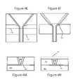
- FIGS. 4A-4Hare schematic top views of a write head at various states of production.
- FIGS. 4I-4Pare schematic cross sectional views of FIGS. 4A-4H respectively.
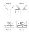
- FIGS. 5A-5Hare schematic top views of a write head at various states of production according to another embodiment.
- FIGS. 5I-5Pare schematic cross sectional views of FIGS. 4A-4H respectively.
- the present inventiongenerally relates to a perpendicular write head having a wrap around shield and a conformal side gap.
- the leading edge shieldmay be chemical mechanical polished down to a level that is substantially even with a chemical mechanical polishing stop layer. Because the leading edge shield and the chemical mechanical polishing stop layer are substantially planar, the gap layer may be conformally deposited.
- the embodiments disclosed hereininclude designs and methods of making damascene based high density perpendicular magnetic recording heads with leading edge shields (LES), leading edge taper (LET), self-aligned conformal side gap, and low magnetic flux density (Bs) side shields.
- the embodiments disclosed hereinenables conformal side gap below (80 nm) nm (which is preferred for high density heads over 750 Gbits/in 2 ) in damascene based four sided wrap around shield writers.
- the conformal side shieldis magnetically connected with leading edge shield and will improve the bit error rate (BER) and minimize adjacent track interference (ATI) in the high performance recording heads.
- Part of LES(or LES' in certain embodiments) works as a reactive ion etch (RIE) stop and enables a complete four-sided WAS without footing.
- RIEreactive ion etch
- a CMP stopfor example, Ru or Ir
- fabricated at LES processalso works as RIE stop together with LES' for trench RIE.
- FIG. 1Ais a cross sectional view of a write head 100 according to one embodiment.
- the write headcomprises a first leading edge shield layer 102 .
- the first leading edge shield layer 102may comprise a ferromagnetic material.
- the first leading edge shield layer 102may comprise an alloy of nickel and iron such as NiFe 20 .
- a second leading edge shield layer 104may be deposited.
- the second leading edge shield layer 104may comprise a ferromagnetic material.
- the second leading edge shield layer 104may comprise an alloy of nickel and iron such as NiFe 20 .
- the second leading edge shield layer 104will be tapered.
- part of the first leading edge shield layer 102acts as an RIE stop layer to enable complete four-sided WAS without footing or disconnection between leading edge shield and side shield.
- a side shield 106is formed over the second leading edge shield layer 104 .
- the side shield layer 106may comprise a ferromagnetic material.
- the side shield layer 106may comprise an alloy of nickel and iron such as NiFe 30 .
- the side shield layer 106may have a higher magnetic moment than both the first and second leading edge shield layers 102 , 104 .
- the side shield layer 106may be etched to form a trench. Within the trench, the side gap layer 108 is formed.
- the side gap layer 108may comprise ruthenium.
- the side gap layer 108may comprise a non-magnetic material.
- the side gap layer 108may comprise iridium.
- the side gap layer 108may have a thickness of between about 50 nm to about 100 nm.
- a magnetic layer 110is deposited.
- the magnetic layer 110may comprise a ferromagnetic material selected from the group consisting of nickel, cobalt, iron, and combinations thereof.
- a write gap layer 112may be formed.
- the write gap layer 112may comprise a non-magnetic material.
- the write gap layer 112may comprise alumina.
- the write gap layer 112may comprise nickel-chromium.
- the write gap layer 112may have a thickness of between about 20 nm to about 25 nm.
- a high Bs seed layer 114may be deposited.
- the high Bs seed layer 114may comprise cobalt, nickel, iron, or combinations thereof. In one embodiment, the high Bs seed layer 114 may comprise CoNiFe. In one embodiment, the high Bs seed layer 114 may comprise a high magnetic moment material. In one embodiment, the high Bs seed layer 114 may have a magnetic flux density of between about 2.0 Tesla and about 2.4 Tesla. Over the side shield 106 and the high Bs seed 114 , a trailing shield layer 116 may be deposited. In one embodiment, the trailing shield layer 116 may have a magnetic flux density of between about 1.5 Tesla and about 1.8 Tesla. In another embodiment, the trailing shield layer 116 may comprise a ferromagnetic material.
- the trailing shield layer 116may be selected from NiFe 45 , NiFe 55 , or other magnetic material having a higher magnetic moment. While not shown, a seed layer having substantially the same composition as the trailing edge shield layer 116 may be deposited prior to depositing the trailing edge shield layer 116 .
- FIG. 1Bis a cross sectional view of a write head 150 according to another embodiment.
- the write head 150 of FIG. 1Bincludes layers, materials, and properties similar to FIG. 1A .
- write head 150includes a first leading edge shield layer 152 , a second leading edge shield layer 154 , a side shield 156 , a write gap layer 162 , a high Bs seed layer 164 , a trailing shield 166 , a magnetic layer 160 , and a side gap layer 158 .
- write head 150also includes a seed layer 168 .
- the use of both the seed layer 168 and the side gap layer 158collectively can be used to control the thickness of the side gap.
- Part of the first leading edge shield layer 152will function as a RIE stop layer and enable complete four-sided WAS without footing.
- FIG. 1Cis a cross sectional view of FIGS. 1A and 1B .
- the write head of FIG. 1Cis the cross-sectional view for the write heads of FIGS. 1A and 1B .
- the second leading edge shield layer 104 / 154is tapered.
- the first leading edge shield layer 102 / 152is adjacent an insulating layer 172 .
- the insulating layer 172may comprise alumina.
- an RIE stop layer 170is deposited.
- the write gap layer and the side gap layerare both tapered to form a tapered pole 174 .
- the cap 178is also tapered 176 .
- the cap 178may comprise tantalum.
- the cap 178may comprise ruthenium. In another embodiment, the cap 178 may comprise a multi-layer stack of tantalum/ruthenium/tantalum. In another embodiment, the cap 178 may comprise an alloy of tantalum and ruthenium. Over the cap 178 , a second insulating layer 180 may be deposited. In one embodiment, the second insulating layer 180 may comprise alumina.
- FIGS. 1A-1Cpermits independent control of the side shield thickness. In FIG. 1A , the side gap layer is conformal and the side shield 106 is fully connected with the leading edge shield. In FIG. 1B , the side gap layer is composed of the side gap layer 158 and seed layer 168 .
- FIG. 2Ais a cross sectional view of a write head 200 according to one embodiment.
- the write head 200 of FIG. 2Aincludes layers, materials, and properties similar to FIG. 1A . However, the write head 200 of FIG. 2A has neither a first nor a second leading edge shield. Rather, the write head 200 has an insulating substrate 202 . In one embodiment, the insulating substrate 202 may comprise alumina.
- the write head 200also includes a RIE stop layer 204 . In one embodiment, the RIE stop layer 204 includes ruthenium, NiCr, or Ru/NiCr. The RIE stop layer 204 and the insulating substrate 202 are substantially planar and not tapered.
- the write head 200also includes a side shield 206 , a write gap layer 212 , a high Bs seed layer 214 , a trailing shield 216 , a magnetic layer 210 , and a side gap layer 258 .
- FIG. 2Bis a cross sectional view of a write head 250 according to another embodiment.
- the write head 250 of FIG. 2Bincludes layers, materials, and properties similar to FIG. 2A .
- write head 250includes an insulating substrate 252 , a RIE stop layer 254 , a side shield 256 , a write gap layer 262 , a high Bs seed layer 264 , a trailing shield 266 , a magnetic layer 260 , and a side gap layer 258 .
- write head 250also includes a seed layer 268 that is deposited in the trench before depositing the side gap layer 258 . The use of both the seed layer 268 and the side gap layer 258 collectively can be used to control the thickness of the side gap.
- FIG. 2Cis a cross sectional view of a write head according to another embodiment.
- the write head of FIG. 2Cis the cross-sectional view for the write heads of FIGS. 2A and 2B .
- the insulating substrate 202 / 252 , the RIE stop layer 204 / 254 , and the side gap layer 208 / 258are not tapered.
- the write gap layeris tapered to form a tapered pole 270 .
- the cap 274is also tapered 272 .
- the cap 274may comprise tantalum.
- the cap 274may comprise ruthenium.
- the cap 274may comprise a multi-layer stack of tantalum/ruthenium/tantalum.
- the cap 274may comprise an alloy of tantalum and ruthenium.
- a second insulating layer 276may be deposited over the cap 274 .
- the second insulating layer 276may comprise alumina.
- FIGS. 3A-3Fare schematic cross sectional views of a write head at various stages of production.
- a sacrificial masking layer 304is deposited over a substrate.
- the sacrificial masking layer 304may comprise a ferromagnetic material, such as NiFe.
- the sacrificial masking layer 304may be deposited by conventional deposition processes such as electro chemical plating.
- the sacrificial masking layer 304is then patterned. The patterning may occur by depositing a hard mask thereover and milling the exposed sacrificial masking layer 304 .
- a photoresist maskmay be formed over the sacrificial masking layer 304 and the exposed sacrificial masking layer 304 may be removed to expose at least a portion of the substrate.
- an insulating layer 302may be deposited over the substrate and the sacrificial masking layer 304 .
- the insulating layer 302may be deposited by a blanket deposition process so that it deposited not only over the substrate, but also over the sacrificial masking layer 304 .
- the insulating layer 302may then be polished to remove the insulating layer 302 that overlies the sacrificial masking layer 304 . The polishing may occur by CMP.
- the sacrificial masking layer 304functions as a CMP stop layer during the polishing of the insulating layer 302 .
- a CMP stop layermay also be added to enhance the CMP uniformity of the leading edge shield to be deposited.
- the sacrificial masking layer 304may then be removed. In one embodiment, the sacrificial masking layer 304 may be removed by a wet etching process.
- a CMP stop layer 306may be deposited.
- the CMP stop layer 306may comprise a non-magnetic material.
- the CMP stop layer 306may comprise iridium.
- the CMP stop layer 306may comprise ruthenium.
- the CMP stop layer 306may be deposited by atomic layer deposition or physical vapor deposition.
- a first leading edge shield layer 308may be deposited. In one embodiment, the first leading edge shield layer 308 may be deposited by electroplating.
- the first leading edge shield layer 308may comprise one or more of iron, nickel, cobalt, and combinations thereof such as CoNiFe, NiFe or NiFe 20 .
- the first leading edge shield layermay have a magnetic flux density of between about 1.0 Tesla and about 2.0 Tesla.
- the first leading edge shield layer 308may be deposited by placing a hard mask over the CMP stop layer 306 and then electroplating the first leading edge shield layer 308 over the exposed portions of the CMP stop layer 306 . The hard mask may then be removed.
- the vertical edge of the first leading edge shield layer 308 and the CMP stop layer 306determines the leading edge shield thickness.
- the first heading edge shield layer 308may have a thickness of between about 100 nm and about 500 nm. Both the CMP stop layer 306 and the first leading edge shield layer 308 will serve as a RIE stop during the trench RIE process.
- the first leading edge shield layer 308may then be planarized using the CMP stop layer 306 as the stopping point for the CMP process. After the CMP process, the first leading edge shield layer 308 and the CMP stop layer 306 are substantially planar.
- a second leading edge shield layer 310may then be deposited over the first leading edge shield layer 308 as well as the CMP stop layer 306 .
- the second leading edge shield layer 310may be selected from the same materials as the first leading edge shield layer 308 . However, the second leading edge shield layer 310 and the first leading edge shield layer 308 may be different.
- the second leading edge shield layer 310will serve as a RIE stop in the leading edge taper region.
- a leading edge tapering millis performed to taper the second leading edge shield layer 310 .
- a resist mask 312is formed over the second leading edge shield layer 310 to define the areas of the second leading edge shield layer 310 that are to be milled.
- the taper portion of the second leading edge shield layer 310will be the base for the leading edge taper in the main pole.
- the resist 312may be stripped and an insulating layer 314 may be deposited and planarized.
- the insulating layer 314may comprise alumina.
- the insulating layer 314will be the base material of the damascene trench.
- the second leading edge shield layer 310 and the CMP stop layer 306will be used as the RIE stop layers for the insulating layer 314 trench formation.
- the second leading edge shield layer 310will be the RIE stop near the pole tip area and the CMP stop layer 306 will be the RIE stop near the yoke area.
- FIGS. 4A-4Hare schematic top views of a write head at various states of production.
- FIGS. 4I-4Pare schematic cross sectional views of FIGS. 4A-4H respectively.
- FIGS. 4A-4Pshows an example of a process flow to form the conformal side gap, side shield, trailing gap, high Bs seed, and trailing shield.
- An example of a structure that may be fabricated by the process described with reference to FIGS. 4A-4Pis the structure shown in FIG. 1A .
- An insulating layer 402is formed over a first leading edge shield layer 410 and a second leading edge shield layer 408 .
- a trenchis etched into the insulating layer 402 .
- the trenchis then filled with a non-magnetic seed layer 404 and then a magnetic layer 406 .
- the insulating layer 402may comprise alumina.
- the non-magnetic seed layer 404may comprise ruthenium.
- the non-magnetic seed layer 404may comprise iridium.
- the magnetic layer 406may comprise a ferromagnetic material.
- the magnetic layer 406may comprise iron, nickel, cobalt, or combinations thereof.
- a photoresist mask 412may then be formed over the insulating layer 402 , magnetic layer 406 , and non-magnetic layer 404 .
- the exposed insulating layer 402may be removed by a reactive ion etching process. Thereafter, the remaining insulating layer 402 may be removed by a wet etching process. In one embodiment, the reactive ion etching process may be eliminated and the insulating layer 402 may be removed by wet etching.
- a magnetic seed layer 414may then be deposited over the exposed second leading edge shield layer 408 , the non-magnetic layer 404 , and the magnetic layer 406 .
- the magnetic seed layer 414may comprise a ferromagnetic material.
- the magnetic seed layer 414may comprise a material selected from the group consisting of iron, cobalt, nickel, and combinations thereof. The magnetic seed layer 414 may be deposited by sputtering.
- the magnetic layer 416may comprise a ferromagnetic material.
- the magnetic layer 416may comprise iron, nickel, cobalt, or combinations thereof.
- the magnetic layer 416is selected from the group consisting of NiFe and CoNiFe.
- the magnetic layer 416may have a magnetic flux density of between about 1.0 Tesla and about 1.3 Tesla.
- the magnetic layer 416 and magnetic seed layer 414may then be polished back using a CMP process.
- the ABS 418is shown by the dashed line.
- the seed layer 404acts as a CMP stop.
- an additional CMP stop layersuch as ruthenium, iridium, rhodium, or diamond like carbon may be used in the area surrounding the yoke and the plated side shield.
- the tapered poleis then formed by ion milling.
- a mask, such as a resist mask or hard maskis to mask the areas of the structure that will not be tapered.
- the portions that are removedare shown in dashed form by numeral 420 .
- the portions that are not removedcreate a trailing edge taper (TET) bump 422 .
- the maskcomprises silicon carbide.
- the hard maskcomprises alumina.
- the write gap layer 424 and high Bs seed layer 426may then be deposited and patterned by photolithography and milling.
- the write gap 424may comprise a non-magnetic material.
- the write gap 424may comprise oxides such as alumina or ruthenium.
- the high Bs layer 426may comprise a ferromagnetic material, such as CoFe or CoNiFe.
- the high Bs layer 426may have a magnetic flux density of between about 2.3 Tesla and about 2.4 Tesla.
- the high Bs layer 426 over the write gap layer 424enhances the field gradient and helps improve the BER.
- the trailing edge shield 428may then be pattered by seed layer deposition, lithography, electroplating, and seed milling.
- the trailing edge shield 428may comprise a ferromagnetic material. In another embodiment, the trailing edge shield 428 may comprise NiFe or CoNiFe. In one embodiment, the trailing edge shield 428 may have a magnetic flux density of between about 1.2 Tesla and about 2.4 Tesla.
- FIGS. 5A-5Hare schematic top views of a write head at various states of production according to another embodiment.
- FIGS. 5I-5Pare schematic cross sectional views of FIGS. 5A-5H respectively.
- FIGS. 5A-5Pshow another examples of a process flow to form a conformal side gap, side shield, trailing gap, high Bs seed layer, and trailing shield. Write heads such as those shown in FIG. 1B may be fabricated by the process flow shown in FIGS. 5A-5P .
- An insulating layer 502is formed over a first leading edge shield layer 510 and a second leading edge shield layer 508 .
- a trenchis etched into the insulating layer 502 .
- the trenchis then filled with a non-magnetic seed layer 504 and then a magnetic layer 506 .
- the insulating layer 502may comprise alumina.
- the non-magnetic seed layer 504may comprise ruthenium.
- the non-magnetic seed layer 504may comprise iridium.
- the magnetic layer 506may comprise a ferromagnetic material.
- the magnetic layer 506may comprise iron, nickel, cobalt, or combinations thereof.
- a photoresist mask 512may then be formed over the insulating layer 502 , magnetic layer 506 , and non-magnetic layer 504 .
- the exposed insulating layer 502may be removed by a reactive ion etching process. Thereafter, the remaining insulating layer 502 may be removed by a wet etching process. In one embodiment, the reactive ion etching process may be eliminated and the insulating layer 502 may be removed by wet etching. Thereafter, the photoresist mask 512 may be removed.
- a non-magnetic seed layer 513may then be deposited.
- the non-magnetic seed layer 513may comprise ruthenium.
- the non-magnetic layer 513may comprise Al 2 O 3 .
- the non-magnetic seed layer 513may be deposited by sputtering.
- the non-magnetic seed layer 513may then be patterned.
- the non-magnetic seed layer 513becomes a part of the side gap and also acts as a CMP stop layer in later processing.
- the total thickness of the side gapwill be the sum of the non-magnetic layer 504 thickness deposited inside the trench and the non-magnetic seed layer 513 deposited outside the trench.
- the side gap thicknessmay be between about 70 nm and about 100 nm.
- the non-magnetic seed layer 513may have a thickness of between about 30 nm and about 50 nm.
- the non-magnetic layer 504may have a thickness of between about 20 nm and about 50 nm.
- the non-magnetic seed layer 513may be deposited by a conformal deposition process such as atomic layer chemical vapor deposition. After the non-magnetic seed layer 513 is deposited, the non-magnetic seed layer 513 may be patterned by photolithography and ion milling.
- a small portion of the non-magnetic seed layer 513remains at the ABS between the side shield and the second leading edge shield layer 508 .
- the impact of the small portionis negligible when the thickness is less than 50 nm for a tail length of up to about 500 nm.
- a magnetic seed layermay then be deposited over the exposed second leading edge shield layer 508 and the non-magnetic seed layer 513 .
- the magnetic seed layermay comprise a ferromagnetic material.
- the magnetic seed layermay comprise a material selected from the group consisting of iron, cobalt, nickel, and combinations thereof. The magnetic seed layer may be deposited by sputtering.
- the magnetic layer 516may comprise a ferromagnetic material such as iron, nickel, cobalt, or combinations thereof.
- the magnetic layer 516is selected from the group consisting of NiFe and CoNiFe.
- the magnetic layer 516may have a magnetic flux density of between about 1.0 Tesla and about 1.8 Tesla.
- the magnetic layer 516 and magnetic seed layermay then be polished back using a CMP process.
- the ABS 518is shown by the dashed line.
- the non-magnetic layer 513acts as a CMP stop which will provide excellent pole thickness uniformity.
- an additional CMP stop layersuch as ruthenium, iridium, rhodium, or diamond like carbon may be used in the area surrounding the yoke and the plated side shield.
- the tapered poleis then formed by ion milling.
- a mask, such as a resist mask or hard maskis to mask the areas of the structure that will not be tapered.
- the portions that are removedare shown in dashed form by numeral 520 .
- the portions that are not removedcreate a trailing edge taper (TET) bump 522 .
- the maskcomprises silicon carbide.
- the hard maskcomprises alumina.
- the write gap layer 524 and high Bs seed layer 526may then be deposited and patterned by photolithography and milling.
- the write gap 524may comprise a non-magnetic material.
- the write gap 524may comprise oxides such as alumina or ruthenium oxide.
- the high Bs layer 526may comprise a ferromagnetic material.
- the high Bs layer 526may comprise CoFe or CoNiFe.
- the high Bs layer 526may have a magnetic flux density of between about 2.3 Tesla and about 2.4 Tesla. The high Bs layer 526 over the write gap layer 524 enhances the field gradient and helps improve the BER.
- the trailing edge shield 528may then be pattered by seed layer deposition, lithography, electroplating, and seed milling.
- the trailing edge shield 528may comprise a ferromagnetic material.
- the trailing edge shield 528may comprise NiFe or CoNiFe.
- the trailing edge shield 528may have a magnetic flux density of between about 1.2 Tesla and about 2.4 Tesla.
- the gap layermay be conformally deposited. In so doing, the conformal side shield is magnetically connected with the leading edge shield which will improve the device performance.
Landscapes
- Engineering & Computer Science (AREA)
- Manufacturing & Machinery (AREA)
- Physics & Mathematics (AREA)
- Electromagnetism (AREA)
- Magnetic Heads (AREA)
Abstract
Description
Claims (20)
Priority Applications (2)
| Application Number | Priority Date | Filing Date | Title |
|---|---|---|---|
| US12/954,458US8470186B2 (en) | 2010-11-24 | 2010-11-24 | Perpendicular write head with wrap around shield and conformal side gap |
| JP2011240955AJP2012113803A (en) | 2010-11-24 | 2011-11-02 | Write head fabricating method |
Applications Claiming Priority (1)
| Application Number | Priority Date | Filing Date | Title |
|---|---|---|---|
| US12/954,458US8470186B2 (en) | 2010-11-24 | 2010-11-24 | Perpendicular write head with wrap around shield and conformal side gap |
Publications (2)
| Publication Number | Publication Date |
|---|---|
| US20120125885A1 US20120125885A1 (en) | 2012-05-24 |
| US8470186B2true US8470186B2 (en) | 2013-06-25 |
Family
ID=46063347
Family Applications (1)
| Application Number | Title | Priority Date | Filing Date |
|---|---|---|---|
| US12/954,458Expired - Fee RelatedUS8470186B2 (en) | 2010-11-24 | 2010-11-24 | Perpendicular write head with wrap around shield and conformal side gap |
Country Status (2)
| Country | Link |
|---|---|
| US (1) | US8470186B2 (en) |
| JP (1) | JP2012113803A (en) |
Cited By (23)
| Publication number | Priority date | Publication date | Assignee | Title |
|---|---|---|---|---|
| US8582238B1 (en)* | 2011-10-21 | 2013-11-12 | Western Digital (Fremont), Llc | Systems and methods for providing perpendicular magnetic writers having gradient magnetic moment side shields |
| US8619389B1 (en)* | 2013-02-26 | 2013-12-31 | Tdk Corporation | Magnetic head for perpendicular magnetic recording having a write shield |
| US20140022673A1 (en)* | 2011-03-28 | 2014-01-23 | Seagate Technology Llc | Write head with modified side shields |
| US8724259B1 (en)* | 2012-06-11 | 2014-05-13 | Western Digital (Fremont), Llc | Conformal high moment side shield seed layer for perpendicular magnetic recording writer |
| US8797686B1 (en)* | 2010-12-23 | 2014-08-05 | Western Digital (Fremont), Llc | Magnetic recording transducer with short effective throat height and method of fabrication |
| US8817418B1 (en)* | 2013-08-15 | 2014-08-26 | Tdk Corporation | Magnetic head for perpendicular magnetic recording having a write shield |
| US8867168B2 (en) | 2012-12-07 | 2014-10-21 | Tdk Corporation | Magnetic head for perpendicular magnetic recording having a write shield |
| US8982508B1 (en)* | 2011-10-31 | 2015-03-17 | Western Digital (Fremont), Llc | Method for providing a side shield for a magnetic recording transducer |
| US9042051B2 (en) | 2013-08-15 | 2015-05-26 | Western Digital (Fremont), Llc | Gradient write gap for perpendicular magnetic recording writer |
| US9082423B1 (en) | 2013-12-18 | 2015-07-14 | Western Digital (Fremont), Llc | Magnetic recording write transducer having an improved trailing surface profile |
| US9111550B1 (en) | 2014-12-04 | 2015-08-18 | Western Digital (Fremont), Llc | Write transducer having a magnetic buffer layer spaced between a side shield and a write pole by non-magnetic layers |
| US9153253B2 (en)* | 2014-01-08 | 2015-10-06 | Tdk Corporation | Perpendicular magnetic recording head and magnetic recording unit having leading shield including exposed end surface and recess shield including mid part |
| US9214165B1 (en) | 2014-12-18 | 2015-12-15 | Western Digital (Fremont), Llc | Magnetic writer having a gradient in saturation magnetization of the shields |
| US9263067B1 (en) | 2013-05-29 | 2016-02-16 | Western Digital (Fremont), Llc | Process for making PMR writer with constant side wall angle |
| US9275657B1 (en) | 2013-08-14 | 2016-03-01 | Western Digital (Fremont), Llc | Process for making PMR writer with non-conformal side gaps |
| US9286919B1 (en) | 2014-12-17 | 2016-03-15 | Western Digital (Fremont), Llc | Magnetic writer having a dual side gap |
| US9361912B1 (en)* | 2015-04-20 | 2016-06-07 | Headway Technologies, Inc. | High moment side shield design for area density improvement of perpendicular magnetic recording (PMR) writer |
| US9478236B1 (en)* | 2012-09-28 | 2016-10-25 | Western Digital (Fremont), Llc | Perpendicular magnetic recording write head |
| US9508364B1 (en)* | 2015-09-09 | 2016-11-29 | Headway Technologies, Inc. | Perpendicular magnetic recording (PMR) writer with hybrid shield layers |
| US9595273B1 (en) | 2015-09-30 | 2017-03-14 | Western Digital (Fremont), Llc | Shingle magnetic writer having nonconformal shields |
| US9711168B1 (en) | 2016-05-17 | 2017-07-18 | Western Digital (Fremont), Llc | Method for providing a magnetic recording write apparatus by predefining side shields |
| US9741366B1 (en) | 2014-12-18 | 2017-08-22 | Western Digital (Fremont), Llc | Method for fabricating a magnetic writer having a gradient in saturation magnetization of the shields |
| US9972345B1 (en)* | 2015-12-18 | 2018-05-15 | Seagate Technology Llc | Method for making a write head for magnetic recording |
Families Citing this family (16)
| Publication number | Priority date | Publication date | Assignee | Title |
|---|---|---|---|---|
| US8842389B2 (en)* | 2009-10-26 | 2014-09-23 | Headway Technologies, Inc. | Wrap-around shielded writer with highly homogeneous shield material |
| US8636913B2 (en)* | 2011-12-21 | 2014-01-28 | HGST Netherlands B.V. | Removing residues in magnetic head fabrication |
| US8703397B1 (en) | 2012-03-29 | 2014-04-22 | Western Digital (Fremont), Llc | Method for providing side shields for a magnetic recording transducer |
| US8861316B2 (en)* | 2012-12-18 | 2014-10-14 | Seagate Technology Llc | Write pole for recording head |
| US8780499B2 (en)* | 2012-12-19 | 2014-07-15 | HGST Netherlands B.V. | Magnetic write head having a residual shield seed layer for reducing overwriting |
| US8842390B2 (en)* | 2013-01-18 | 2014-09-23 | Seagate Technology Llc | Write pole box shield |
| US9394164B2 (en)* | 2013-03-12 | 2016-07-19 | Taiwan Semiconductor Manufacturing Company, Ltd. | MEMS method and structure |
| US9036299B2 (en) | 2013-07-24 | 2015-05-19 | HGST Netherlands B.V. | Magnetic write head having a recessed high moment portion of the wrap-around shield |
| US9001467B1 (en) | 2014-03-05 | 2015-04-07 | Western Digital (Fremont), Llc | Method for fabricating side shields in a magnetic writer |
| US10032469B2 (en)* | 2015-11-05 | 2018-07-24 | Headway Technologies, Inc. | Perpendicular magnetic recording (PMR) writer with improved trailing shield design |
| US9508367B1 (en)* | 2016-02-03 | 2016-11-29 | International Business Machines Corporation | Tunnel magnetoresistive sensor having conductive ceramic layers |
| JP6527480B2 (en)* | 2016-03-04 | 2019-06-05 | 株式会社東芝 | Magnetic recording head and magnetic recording apparatus |
| US10121742B2 (en)* | 2017-03-15 | 2018-11-06 | Amkor Technology, Inc. | Method of forming a packaged semiconductor device using ganged conductive connective assembly and structure |
| US10468054B1 (en)* | 2018-08-22 | 2019-11-05 | Western Digital Technologies, Inc. | Write head having a monolithic side sheild and leading shield |
| US10832710B1 (en)* | 2019-09-09 | 2020-11-10 | Western Digital Technologies, Inc. | Magnetic recording devices using virtual side shields for improved areal density capability |
| JP7332507B2 (en)* | 2020-03-17 | 2023-08-23 | 株式会社東芝 | magnetic head |
Citations (46)
| Publication number | Priority date | Publication date | Assignee | Title |
|---|---|---|---|---|
| US6501619B1 (en) | 2000-04-27 | 2002-12-31 | Shipley Company, L.L.C. | Inductive magnetic recording head having inclined magnetic read/write pole and method of making same |
| US6989972B1 (en) | 2002-09-30 | 2006-01-24 | Western Digital (Fremont), Inc. | Magnetoresistive sensor with overlapping leads having distributed current |
| US7038882B2 (en) | 2002-10-03 | 2006-05-02 | Seagate Technology | Low moment-high moment write pole with non-magnetic layer for establishing a magnetic path discontinuity between layers of the write pole |
| JP2006147023A (en) | 2004-11-18 | 2006-06-08 | Fujitsu Ltd | Thin film magnetic head and manufacturing method thereof |
| US7075756B1 (en) | 2002-11-07 | 2006-07-11 | Maxtor Corporation | Shielded pole writer |
| US20060187581A1 (en) | 2005-02-24 | 2006-08-24 | Fujitsu Limited | Magnetic head and method of manufacturing the same |
| US7140095B2 (en) | 2003-03-31 | 2006-11-28 | Sae Magnetics (H.K.) Ltd. | Method of manufacturing a thin film magnetic head |
| US20060279882A1 (en) | 2005-06-14 | 2006-12-14 | Kenji Honda | Magnetic detecting element having rie-resistant film and method of manufacturing the same |
| US7159302B2 (en) | 2004-03-31 | 2007-01-09 | Hitachi Global Storage Technologies Netherlands B.V. | Method for manufacturing a perpendicular write head |
| US7251878B2 (en) | 2004-06-30 | 2007-08-07 | Hitachi Global Storage Technologies Netherlands B.V. | Method and apparatus for defining leading edge taper of a write pole tip |
| US7253992B2 (en) | 2004-11-04 | 2007-08-07 | Hitachi Global Storage Technologies Netherlands, B.V. | Single-pole recording head having trapezoidal main pole and bevel angle promotion layer and methods of fabricating the same |
| US20070217069A1 (en) | 2006-03-15 | 2007-09-20 | Hitachi Global Storage Technologies Netherlands B.V. | Perpendicular magnetic recording head and method of manufacturing the same |
| US20070253117A1 (en) | 2006-04-17 | 2007-11-01 | Hitachi Global Storage Technologies Inc. | Magnetic head and method for fabricating the same |
| US20080112081A1 (en) | 2006-11-10 | 2008-05-15 | Sae Magnetics (H.K.) Ltd. | Perpendicular magnetic write head, method of manufacturing the same, and magnetic recording apparatus |
| US7375925B2 (en) | 2005-05-27 | 2008-05-20 | Headway Technologies, Inc. | Magnetic head for perpendicular magnetic recording and method of manufacturing same |
| US7392577B2 (en) | 2003-09-12 | 2008-07-01 | Tdk Corporation | Method for manufacturing a perpendicular magnetic head |
| US20080155810A1 (en) | 2006-12-27 | 2008-07-03 | Ying Hong | Methods for fabricating a magnetic sensor head using a cmp defined hard bias and a totally flat reader gap |
| US7417824B2 (en) | 2004-11-10 | 2008-08-26 | Tdk Corporation | Perpendicular magnetic recording head where main magnetic pole having inclined surface is formed and method of manufacturing the same |
| US20080239585A1 (en) | 2007-01-04 | 2008-10-02 | Hitachi Global Storage Technologies Netherlands B.V. | CPP-type magnetoresistive effect head and method of manufacturing the same |
| US20080239567A1 (en) | 2007-03-26 | 2008-10-02 | Headway Technologies, Inc. | Magnetic head for perpendicular magnetic recording and method of manufacturing same |
| US20080253035A1 (en) | 2007-03-27 | 2008-10-16 | Headway Technologies, Inc. | Self-aligned full side shield PMR and method to make it |
| US20080259498A1 (en) | 2007-04-19 | 2008-10-23 | Hitachi Global Storage Technologies | Perpendicular write head with independent trailing shield designs |
| US20080266724A1 (en) | 2007-04-25 | 2008-10-30 | Tdk Corporation | Perpendicular magnetic recording head |
| US20080266710A1 (en) | 2007-04-25 | 2008-10-30 | Tdk Corporation | Perpendicular magnetic recording head |
| US20080278862A1 (en) | 2007-05-08 | 2008-11-13 | Tdk Corporation | Perpendicular magnetic recording head |
| US20080278861A1 (en) | 2007-05-11 | 2008-11-13 | Ming Jiang | Stitched wrap around shield fabrication for perpendicular magnetic recording write heads |
| US20080278853A1 (en) | 2007-05-08 | 2008-11-13 | Tdk Corporation | Perpendicular magnetic recording head |
| US20090002885A1 (en) | 2007-06-28 | 2009-01-01 | Samsung Electronics Co., Ltd. | Perpendicular magnetic recording head and method of manufacturing the same |
| JP2009048719A (en) | 2007-08-21 | 2009-03-05 | Hitachi Global Storage Technologies Netherlands Bv | Magnetic head and magnetic recording apparatus |
| US20090122445A1 (en) | 2007-11-13 | 2009-05-14 | Hitachi Global Storage Technologies Netherlands B.V. | Perpendicular magnetic recording write head with flux shaping layers on the write pole and magnetic recording system incorporating the write head |
| US20090141406A1 (en) | 2007-12-04 | 2009-06-04 | Headway Technologies, Inc. | Magnetic head for perpendicular magnetic recording and method of manufacturing same |
| US20090147410A1 (en) | 2007-12-06 | 2009-06-11 | Hitachi Global Storage Technologies Netherlands B.V. | Perpendicular magnetic recording write head with magnetic shields separated by nonmagnetic layers |
| US20090154019A1 (en) | 2007-12-17 | 2009-06-18 | Hitachi Global Storage Technologies Netherlands B.V. | Perpendicular magnetic recording write head with slanted magnetic write pole |
| US20090152119A1 (en) | 2007-12-14 | 2009-06-18 | Fujitsu Limited | Method for manufacturing magnetic head |
| US7561384B2 (en) | 2004-12-21 | 2009-07-14 | Hitachi Global Storage Technologies Netherlands B.V. | Magneto-resistive sensor having small track width and sensor height using stopper layer |
| JP2009187612A (en) | 2008-02-05 | 2009-08-20 | Fujitsu Ltd | Manufacturing method of magnetic head |
| JP2009199712A (en) | 2008-02-25 | 2009-09-03 | Headway Technologies Inc | Vertical magnetic recording head and its manufacturing method |
| US20090244789A1 (en) | 2008-04-01 | 2009-10-01 | Westem Digital (Fremont), Llc | Method and system for providing a hard bias capping layer |
| JP2009224000A (en) | 2008-03-18 | 2009-10-01 | Fujitsu Ltd | Method of manufacturing magnetic head |
| JP2009238261A (en) | 2008-03-26 | 2009-10-15 | Fujitsu Ltd | Reproduction magnetic head and manufacturing method thereof |
| US20090266790A1 (en) | 2008-04-28 | 2009-10-29 | Hamid Balamane | Method of making a magnetoresistive reader structure |
| US20090283205A1 (en) | 2008-05-16 | 2009-11-19 | Fujitsu Limited | Method of manufacturing a thin-film magnetic head |
| US7623324B2 (en) | 2005-06-22 | 2009-11-24 | Tdk Corporation | Magnetic sensing element having reactive-ion-etching stop layer and process for producing same |
| US20100024201A1 (en) | 2008-07-31 | 2010-02-04 | Quang Le | Method for fabricating narrow magnetic read width tmr/cpp sensors |
| JP2010033621A (en) | 2008-07-24 | 2010-02-12 | Fujitsu Ltd | Magnetic head, manufacturing method therefor, and magnetic storage device |
| JP2010061735A (en) | 2008-09-03 | 2010-03-18 | Fujitsu Ltd | Magnetic head and method for manufacturing the same and information storage device |
- 2010
- 2010-11-24USUS12/954,458patent/US8470186B2/ennot_activeExpired - Fee Related
- 2011
- 2011-11-02JPJP2011240955Apatent/JP2012113803A/enactivePending
Patent Citations (46)
| Publication number | Priority date | Publication date | Assignee | Title |
|---|---|---|---|---|
| US6501619B1 (en) | 2000-04-27 | 2002-12-31 | Shipley Company, L.L.C. | Inductive magnetic recording head having inclined magnetic read/write pole and method of making same |
| US6989972B1 (en) | 2002-09-30 | 2006-01-24 | Western Digital (Fremont), Inc. | Magnetoresistive sensor with overlapping leads having distributed current |
| US7038882B2 (en) | 2002-10-03 | 2006-05-02 | Seagate Technology | Low moment-high moment write pole with non-magnetic layer for establishing a magnetic path discontinuity between layers of the write pole |
| US7075756B1 (en) | 2002-11-07 | 2006-07-11 | Maxtor Corporation | Shielded pole writer |
| US7140095B2 (en) | 2003-03-31 | 2006-11-28 | Sae Magnetics (H.K.) Ltd. | Method of manufacturing a thin film magnetic head |
| US7392577B2 (en) | 2003-09-12 | 2008-07-01 | Tdk Corporation | Method for manufacturing a perpendicular magnetic head |
| US7159302B2 (en) | 2004-03-31 | 2007-01-09 | Hitachi Global Storage Technologies Netherlands B.V. | Method for manufacturing a perpendicular write head |
| US7251878B2 (en) | 2004-06-30 | 2007-08-07 | Hitachi Global Storage Technologies Netherlands B.V. | Method and apparatus for defining leading edge taper of a write pole tip |
| US7253992B2 (en) | 2004-11-04 | 2007-08-07 | Hitachi Global Storage Technologies Netherlands, B.V. | Single-pole recording head having trapezoidal main pole and bevel angle promotion layer and methods of fabricating the same |
| US7417824B2 (en) | 2004-11-10 | 2008-08-26 | Tdk Corporation | Perpendicular magnetic recording head where main magnetic pole having inclined surface is formed and method of manufacturing the same |
| JP2006147023A (en) | 2004-11-18 | 2006-06-08 | Fujitsu Ltd | Thin film magnetic head and manufacturing method thereof |
| US7561384B2 (en) | 2004-12-21 | 2009-07-14 | Hitachi Global Storage Technologies Netherlands B.V. | Magneto-resistive sensor having small track width and sensor height using stopper layer |
| US20060187581A1 (en) | 2005-02-24 | 2006-08-24 | Fujitsu Limited | Magnetic head and method of manufacturing the same |
| US7375925B2 (en) | 2005-05-27 | 2008-05-20 | Headway Technologies, Inc. | Magnetic head for perpendicular magnetic recording and method of manufacturing same |
| US20060279882A1 (en) | 2005-06-14 | 2006-12-14 | Kenji Honda | Magnetic detecting element having rie-resistant film and method of manufacturing the same |
| US7623324B2 (en) | 2005-06-22 | 2009-11-24 | Tdk Corporation | Magnetic sensing element having reactive-ion-etching stop layer and process for producing same |
| US20070217069A1 (en) | 2006-03-15 | 2007-09-20 | Hitachi Global Storage Technologies Netherlands B.V. | Perpendicular magnetic recording head and method of manufacturing the same |
| US20070253117A1 (en) | 2006-04-17 | 2007-11-01 | Hitachi Global Storage Technologies Inc. | Magnetic head and method for fabricating the same |
| US20080112081A1 (en) | 2006-11-10 | 2008-05-15 | Sae Magnetics (H.K.) Ltd. | Perpendicular magnetic write head, method of manufacturing the same, and magnetic recording apparatus |
| US20080155810A1 (en) | 2006-12-27 | 2008-07-03 | Ying Hong | Methods for fabricating a magnetic sensor head using a cmp defined hard bias and a totally flat reader gap |
| US20080239585A1 (en) | 2007-01-04 | 2008-10-02 | Hitachi Global Storage Technologies Netherlands B.V. | CPP-type magnetoresistive effect head and method of manufacturing the same |
| US20080239567A1 (en) | 2007-03-26 | 2008-10-02 | Headway Technologies, Inc. | Magnetic head for perpendicular magnetic recording and method of manufacturing same |
| US20080253035A1 (en) | 2007-03-27 | 2008-10-16 | Headway Technologies, Inc. | Self-aligned full side shield PMR and method to make it |
| US20080259498A1 (en) | 2007-04-19 | 2008-10-23 | Hitachi Global Storage Technologies | Perpendicular write head with independent trailing shield designs |
| US20080266724A1 (en) | 2007-04-25 | 2008-10-30 | Tdk Corporation | Perpendicular magnetic recording head |
| US20080266710A1 (en) | 2007-04-25 | 2008-10-30 | Tdk Corporation | Perpendicular magnetic recording head |
| US20080278853A1 (en) | 2007-05-08 | 2008-11-13 | Tdk Corporation | Perpendicular magnetic recording head |
| US20080278862A1 (en) | 2007-05-08 | 2008-11-13 | Tdk Corporation | Perpendicular magnetic recording head |
| US20080278861A1 (en) | 2007-05-11 | 2008-11-13 | Ming Jiang | Stitched wrap around shield fabrication for perpendicular magnetic recording write heads |
| US20090002885A1 (en) | 2007-06-28 | 2009-01-01 | Samsung Electronics Co., Ltd. | Perpendicular magnetic recording head and method of manufacturing the same |
| JP2009048719A (en) | 2007-08-21 | 2009-03-05 | Hitachi Global Storage Technologies Netherlands Bv | Magnetic head and magnetic recording apparatus |
| US20090122445A1 (en) | 2007-11-13 | 2009-05-14 | Hitachi Global Storage Technologies Netherlands B.V. | Perpendicular magnetic recording write head with flux shaping layers on the write pole and magnetic recording system incorporating the write head |
| US20090141406A1 (en) | 2007-12-04 | 2009-06-04 | Headway Technologies, Inc. | Magnetic head for perpendicular magnetic recording and method of manufacturing same |
| US20090147410A1 (en) | 2007-12-06 | 2009-06-11 | Hitachi Global Storage Technologies Netherlands B.V. | Perpendicular magnetic recording write head with magnetic shields separated by nonmagnetic layers |
| US20090152119A1 (en) | 2007-12-14 | 2009-06-18 | Fujitsu Limited | Method for manufacturing magnetic head |
| US20090154019A1 (en) | 2007-12-17 | 2009-06-18 | Hitachi Global Storage Technologies Netherlands B.V. | Perpendicular magnetic recording write head with slanted magnetic write pole |
| JP2009187612A (en) | 2008-02-05 | 2009-08-20 | Fujitsu Ltd | Manufacturing method of magnetic head |
| JP2009199712A (en) | 2008-02-25 | 2009-09-03 | Headway Technologies Inc | Vertical magnetic recording head and its manufacturing method |
| JP2009224000A (en) | 2008-03-18 | 2009-10-01 | Fujitsu Ltd | Method of manufacturing magnetic head |
| JP2009238261A (en) | 2008-03-26 | 2009-10-15 | Fujitsu Ltd | Reproduction magnetic head and manufacturing method thereof |
| US20090244789A1 (en) | 2008-04-01 | 2009-10-01 | Westem Digital (Fremont), Llc | Method and system for providing a hard bias capping layer |
| US20090266790A1 (en) | 2008-04-28 | 2009-10-29 | Hamid Balamane | Method of making a magnetoresistive reader structure |
| US20090283205A1 (en) | 2008-05-16 | 2009-11-19 | Fujitsu Limited | Method of manufacturing a thin-film magnetic head |
| JP2010033621A (en) | 2008-07-24 | 2010-02-12 | Fujitsu Ltd | Magnetic head, manufacturing method therefor, and magnetic storage device |
| US20100024201A1 (en) | 2008-07-31 | 2010-02-04 | Quang Le | Method for fabricating narrow magnetic read width tmr/cpp sensors |
| JP2010061735A (en) | 2008-09-03 | 2010-03-18 | Fujitsu Ltd | Magnetic head and method for manufacturing the same and information storage device |
Cited By (29)
| Publication number | Priority date | Publication date | Assignee | Title |
|---|---|---|---|---|
| US8797686B1 (en)* | 2010-12-23 | 2014-08-05 | Western Digital (Fremont), Llc | Magnetic recording transducer with short effective throat height and method of fabrication |
| US20140022673A1 (en)* | 2011-03-28 | 2014-01-23 | Seagate Technology Llc | Write head with modified side shields |
| US8970992B2 (en)* | 2011-03-28 | 2015-03-03 | Seagate Technology Llc | Write head with modified side shields |
| US8582238B1 (en)* | 2011-10-21 | 2013-11-12 | Western Digital (Fremont), Llc | Systems and methods for providing perpendicular magnetic writers having gradient magnetic moment side shields |
| US8982508B1 (en)* | 2011-10-31 | 2015-03-17 | Western Digital (Fremont), Llc | Method for providing a side shield for a magnetic recording transducer |
| US9123358B1 (en) | 2012-06-11 | 2015-09-01 | Western Digital (Fremont), Llc | Conformal high moment side shield seed layer for perpendicular magnetic recording writer |
| US8724259B1 (en)* | 2012-06-11 | 2014-05-13 | Western Digital (Fremont), Llc | Conformal high moment side shield seed layer for perpendicular magnetic recording writer |
| US9478236B1 (en)* | 2012-09-28 | 2016-10-25 | Western Digital (Fremont), Llc | Perpendicular magnetic recording write head |
| US8867168B2 (en) | 2012-12-07 | 2014-10-21 | Tdk Corporation | Magnetic head for perpendicular magnetic recording having a write shield |
| US8619389B1 (en)* | 2013-02-26 | 2013-12-31 | Tdk Corporation | Magnetic head for perpendicular magnetic recording having a write shield |
| US9263067B1 (en) | 2013-05-29 | 2016-02-16 | Western Digital (Fremont), Llc | Process for making PMR writer with constant side wall angle |
| US9275657B1 (en) | 2013-08-14 | 2016-03-01 | Western Digital (Fremont), Llc | Process for making PMR writer with non-conformal side gaps |
| US9042051B2 (en) | 2013-08-15 | 2015-05-26 | Western Digital (Fremont), Llc | Gradient write gap for perpendicular magnetic recording writer |
| US8817418B1 (en)* | 2013-08-15 | 2014-08-26 | Tdk Corporation | Magnetic head for perpendicular magnetic recording having a write shield |
| US9214166B1 (en) | 2013-08-15 | 2015-12-15 | Western Digital (Fremont), Llc | Gradient write gap for perpendicular magnetic recording writer |
| US9082423B1 (en) | 2013-12-18 | 2015-07-14 | Western Digital (Fremont), Llc | Magnetic recording write transducer having an improved trailing surface profile |
| US9153253B2 (en)* | 2014-01-08 | 2015-10-06 | Tdk Corporation | Perpendicular magnetic recording head and magnetic recording unit having leading shield including exposed end surface and recess shield including mid part |
| US9111550B1 (en) | 2014-12-04 | 2015-08-18 | Western Digital (Fremont), Llc | Write transducer having a magnetic buffer layer spaced between a side shield and a write pole by non-magnetic layers |
| US9286919B1 (en) | 2014-12-17 | 2016-03-15 | Western Digital (Fremont), Llc | Magnetic writer having a dual side gap |
| US9214165B1 (en) | 2014-12-18 | 2015-12-15 | Western Digital (Fremont), Llc | Magnetic writer having a gradient in saturation magnetization of the shields |
| US9741366B1 (en) | 2014-12-18 | 2017-08-22 | Western Digital (Fremont), Llc | Method for fabricating a magnetic writer having a gradient in saturation magnetization of the shields |
| US9361912B1 (en)* | 2015-04-20 | 2016-06-07 | Headway Technologies, Inc. | High moment side shield design for area density improvement of perpendicular magnetic recording (PMR) writer |
| US9589582B2 (en)* | 2015-04-20 | 2017-03-07 | Headway Technologies, Inc. | High moment side shield design for area density improvement of perpendicular magnetic recording (PMR) writer |
| US9508364B1 (en)* | 2015-09-09 | 2016-11-29 | Headway Technologies, Inc. | Perpendicular magnetic recording (PMR) writer with hybrid shield layers |
| US20170076742A1 (en)* | 2015-09-09 | 2017-03-16 | Headway Technologies, Inc. | Perpendicular Magnetic Recording (PMR) Writer with Hybrid Shield Layers |
| US9626990B2 (en)* | 2015-09-09 | 2017-04-18 | Headway Technologies, Inc. | Perpendicular magnetic recording (PMR) writer with hybrid shield layers |
| US9595273B1 (en) | 2015-09-30 | 2017-03-14 | Western Digital (Fremont), Llc | Shingle magnetic writer having nonconformal shields |
| US9972345B1 (en)* | 2015-12-18 | 2018-05-15 | Seagate Technology Llc | Method for making a write head for magnetic recording |
| US9711168B1 (en) | 2016-05-17 | 2017-07-18 | Western Digital (Fremont), Llc | Method for providing a magnetic recording write apparatus by predefining side shields |
Also Published As
| Publication number | Publication date |
|---|---|
| JP2012113803A (en) | 2012-06-14 |
| US20120125885A1 (en) | 2012-05-24 |
Similar Documents
| Publication | Publication Date | Title |
|---|---|---|
| US8470186B2 (en) | Perpendicular write head with wrap around shield and conformal side gap | |
| US8400733B2 (en) | Process to make PMR writer with leading edge shield (LES) and leading edge taper (LET) | |
| US8547660B2 (en) | Magnetic write head manufactured by an enhanced damascene process producing a tapered write pole with a non-magnetic spacer and non-magnetic bump | |
| US8201320B2 (en) | Method for manufacturing a magnetic write head having a wrap around shield that is magnetically coupled with a leading magnetic shield | |
| US8347488B2 (en) | Magnetic write head manufactured by damascene process producing a tapered write pole with a non-magnetic step and non-magnetic bump | |
| US8524095B2 (en) | Process to make PMR writer with leading edge shield (LES) and leading edge taper (LET) | |
| US8441757B2 (en) | Perpendicular magnetic write head with wrap-around shield, slanted pole and slanted pole bump fabricated by damascene process | |
| US8323727B2 (en) | Method for manufacturing a perpendicular magnetic write head having a tapered write pole and a stepped wrap around side shield gap | |
| US7715147B2 (en) | Magnetic write head having a shield that extends below the leading edge of the write pole | |
| US7612963B2 (en) | Perpendicular magnetic recording head with photoresist dam between write coil and air bearing surface | |
| US8347489B2 (en) | Method for manufacturing a perpendicular magnetic write head having a leading edge tapered write pole, self aligned side shield and independent trailing shield | |
| US8339734B2 (en) | Magnetic write head having a wrap around trailing shield with an asymetrical side gap | |
| US8110085B2 (en) | Assisted deposition, narrow trench damascene process for manufacturing a write pole of a magnetic write head | |
| US20050024771A1 (en) | Perpendicular recording magnetic head with a write shield magnetically coupled to a first pole piece | |
| US20070258167A1 (en) | Perpendicular magnetic write head having a magnetic write pole with a concave trailing edge | |
| US20070245545A1 (en) | Method of manufacturing a wrap around shield for a perpendicular write pole using a laminated mask | |
| US8451562B2 (en) | Method for manufacturing a magnetic write head having a wrap around trailing magnetic shield with a tapered side gap | |
| JP2007172816A (en) | Method of manufacturing perpendicular magnetic recording head and side shield | |
| US7788798B2 (en) | Method for manufacturing a perpendicular magnetic write head with wrap around magnetic trailing and side shields | |
| US20100155364A1 (en) | Magnetic write head having a stepped trailing shield and write pole with a sloped trailing edge | |
| US8349197B2 (en) | Method for manufacturing a perpendicular magnetic write head having a tapered write pole and non-magnetic bump structure | |
| US8031434B2 (en) | Hybrid, self aligned magnetic write head with a partially plated pole and method of producing same | |
| US8371019B1 (en) | Method for manufacturing a magnetic write pole having straight side walls and a well defined track-width | |
| US8318031B2 (en) | Method for manufacturing a perpendicular magnetic write head having a tapered write pole | |
| US20090273862A1 (en) | Flat e-yoke for cusp write head |
Legal Events
| Date | Code | Title | Description |
|---|---|---|---|
| AS | Assignment | Owner name:HITACHI GLOBAL STORAGE TECHNOLOGIES NETHERLANDS B. Free format text:ASSIGNMENT OF ASSIGNORS INTEREST;ASSIGNORS:CHEN, YINGJIAN;HUANG, SHIWEN;LIU, FENGLIN;AND OTHERS;REEL/FRAME:025449/0137 Effective date:20101118 | |
| AS | Assignment | Owner name:HGST, NETHERLANDS B.V., NETHERLANDS Free format text:CHANGE OF NAME;ASSIGNOR:HGST, NETHERLANDS B.V.;REEL/FRAME:029341/0777 Effective date:20120723 Owner name:HGST NETHERLANDS B.V., NETHERLANDS Free format text:CHANGE OF NAME;ASSIGNOR:HITACHI GLOBAL STORAGE TECHNOLOGIES NETHERLANDS B.V.;REEL/FRAME:029341/0777 Effective date:20120723 | |
| STCF | Information on status: patent grant | Free format text:PATENTED CASE | |
| AS | Assignment | Owner name:WESTERN DIGITAL TECHNOLOGIES, INC., CALIFORNIA Free format text:ASSIGNMENT OF ASSIGNORS INTEREST;ASSIGNOR:HGST NETHERLANDS B.V.;REEL/FRAME:040826/0327 Effective date:20160831 | |
| FPAY | Fee payment | Year of fee payment:4 | |
| AS | Assignment | Owner name:JPMORGAN CHASE BANK, N.A., AS AGENT, ILLINOIS Free format text:SECURITY INTEREST;ASSIGNOR:WESTERN DIGITAL TECHNOLOGIES, INC.;REEL/FRAME:052915/0566 Effective date:20200113 | |
| MAFP | Maintenance fee payment | Free format text:PAYMENT OF MAINTENANCE FEE, 8TH YEAR, LARGE ENTITY (ORIGINAL EVENT CODE: M1552); ENTITY STATUS OF PATENT OWNER: LARGE ENTITY Year of fee payment:8 | |
| AS | Assignment | Owner name:WESTERN DIGITAL TECHNOLOGIES, INC., CALIFORNIA Free format text:RELEASE OF SECURITY INTEREST AT REEL 052915 FRAME 0566;ASSIGNOR:JPMORGAN CHASE BANK, N.A.;REEL/FRAME:059127/0001 Effective date:20220203 | |
| AS | Assignment | Owner name:JPMORGAN CHASE BANK, N.A., ILLINOIS Free format text:PATENT COLLATERAL AGREEMENT - A&R LOAN AGREEMENT;ASSIGNOR:WESTERN DIGITAL TECHNOLOGIES, INC.;REEL/FRAME:064715/0001 Effective date:20230818 Owner name:JPMORGAN CHASE BANK, N.A., ILLINOIS Free format text:PATENT COLLATERAL AGREEMENT - DDTL LOAN AGREEMENT;ASSIGNOR:WESTERN DIGITAL TECHNOLOGIES, INC.;REEL/FRAME:067045/0156 Effective date:20230818 | |
| FEPP | Fee payment procedure | Free format text:MAINTENANCE FEE REMINDER MAILED (ORIGINAL EVENT CODE: REM.); ENTITY STATUS OF PATENT OWNER: LARGE ENTITY | |
| LAPS | Lapse for failure to pay maintenance fees | Free format text:PATENT EXPIRED FOR FAILURE TO PAY MAINTENANCE FEES (ORIGINAL EVENT CODE: EXP.); ENTITY STATUS OF PATENT OWNER: LARGE ENTITY | |
| STCH | Information on status: patent discontinuation | Free format text:PATENT EXPIRED DUE TO NONPAYMENT OF MAINTENANCE FEES UNDER 37 CFR 1.362 | |
| FP | Lapsed due to failure to pay maintenance fee | Effective date:20250625 |