US8470016B2 - Stent and other object removal from a body - Google Patents
Stent and other object removal from a bodyDownload PDFInfo
- Publication number
- US8470016B2 US8470016B2US13/200,301US201113200301AUS8470016B2US 8470016 B2US8470016 B2US 8470016B2US 201113200301 AUS201113200301 AUS 201113200301AUS 8470016 B2US8470016 B2US 8470016B2
- Authority
- US
- United States
- Prior art keywords
- balloon
- catheter
- receiving socket
- lumen
- deployed
- Prior art date
- Legal status (The legal status is an assumption and is not a legal conclusion. Google has not performed a legal analysis and makes no representation as to the accuracy of the status listed.)
- Expired - Fee Related, expires
Links
- 0C*1C(CN)C1Chemical compoundC*1C(CN)C10.000description1
Images


Classifications
- A—HUMAN NECESSITIES
- A61—MEDICAL OR VETERINARY SCIENCE; HYGIENE
- A61F—FILTERS IMPLANTABLE INTO BLOOD VESSELS; PROSTHESES; DEVICES PROVIDING PATENCY TO, OR PREVENTING COLLAPSING OF, TUBULAR STRUCTURES OF THE BODY, e.g. STENTS; ORTHOPAEDIC, NURSING OR CONTRACEPTIVE DEVICES; FOMENTATION; TREATMENT OR PROTECTION OF EYES OR EARS; BANDAGES, DRESSINGS OR ABSORBENT PADS; FIRST-AID KITS
- A61F2/00—Filters implantable into blood vessels; Prostheses, i.e. artificial substitutes or replacements for parts of the body; Appliances for connecting them with the body; Devices providing patency to, or preventing collapsing of, tubular structures of the body, e.g. stents
- A61F2/95—Instruments specially adapted for placement or removal of stents or stent-grafts
- A61F2/958—Inflatable balloons for placing stents or stent-grafts
- A—HUMAN NECESSITIES
- A61—MEDICAL OR VETERINARY SCIENCE; HYGIENE
- A61F—FILTERS IMPLANTABLE INTO BLOOD VESSELS; PROSTHESES; DEVICES PROVIDING PATENCY TO, OR PREVENTING COLLAPSING OF, TUBULAR STRUCTURES OF THE BODY, e.g. STENTS; ORTHOPAEDIC, NURSING OR CONTRACEPTIVE DEVICES; FOMENTATION; TREATMENT OR PROTECTION OF EYES OR EARS; BANDAGES, DRESSINGS OR ABSORBENT PADS; FIRST-AID KITS
- A61F2/00—Filters implantable into blood vessels; Prostheses, i.e. artificial substitutes or replacements for parts of the body; Appliances for connecting them with the body; Devices providing patency to, or preventing collapsing of, tubular structures of the body, e.g. stents
- A61F2/95—Instruments specially adapted for placement or removal of stents or stent-grafts
- A—HUMAN NECESSITIES
- A61—MEDICAL OR VETERINARY SCIENCE; HYGIENE
- A61B—DIAGNOSIS; SURGERY; IDENTIFICATION
- A61B17/00—Surgical instruments, devices or methods
- A61B17/22—Implements for squeezing-off ulcers or the like on inner organs of the body; Implements for scraping-out cavities of body organs, e.g. bones; for invasive removal or destruction of calculus using mechanical vibrations; for removing obstructions in blood vessels, not otherwise provided for
- A61B17/22031—Gripping instruments, e.g. forceps, for removing or smashing calculi
- A—HUMAN NECESSITIES
- A61—MEDICAL OR VETERINARY SCIENCE; HYGIENE
- A61M—DEVICES FOR INTRODUCING MEDIA INTO, OR ONTO, THE BODY; DEVICES FOR TRANSDUCING BODY MEDIA OR FOR TAKING MEDIA FROM THE BODY; DEVICES FOR PRODUCING OR ENDING SLEEP OR STUPOR
- A61M25/00—Catheters; Hollow probes
- A61M25/10—Balloon catheters
- A61M25/1002—Balloon catheters characterised by balloon shape
- A—HUMAN NECESSITIES
- A61—MEDICAL OR VETERINARY SCIENCE; HYGIENE
- A61M—DEVICES FOR INTRODUCING MEDIA INTO, OR ONTO, THE BODY; DEVICES FOR TRANSDUCING BODY MEDIA OR FOR TAKING MEDIA FROM THE BODY; DEVICES FOR PRODUCING OR ENDING SLEEP OR STUPOR
- A61M25/00—Catheters; Hollow probes
- A61M25/10—Balloon catheters
- A61M25/1027—Making of balloon catheters
- A—HUMAN NECESSITIES
- A61—MEDICAL OR VETERINARY SCIENCE; HYGIENE
- A61B—DIAGNOSIS; SURGERY; IDENTIFICATION
- A61B17/00—Surgical instruments, devices or methods
- A61B17/22—Implements for squeezing-off ulcers or the like on inner organs of the body; Implements for scraping-out cavities of body organs, e.g. bones; for invasive removal or destruction of calculus using mechanical vibrations; for removing obstructions in blood vessels, not otherwise provided for
- A61B17/22031—Gripping instruments, e.g. forceps, for removing or smashing calculi
- A61B17/22032—Gripping instruments, e.g. forceps, for removing or smashing calculi having inflatable gripping elements
- A—HUMAN NECESSITIES
- A61—MEDICAL OR VETERINARY SCIENCE; HYGIENE
- A61B—DIAGNOSIS; SURGERY; IDENTIFICATION
- A61B17/00—Surgical instruments, devices or methods
- A61B17/22—Implements for squeezing-off ulcers or the like on inner organs of the body; Implements for scraping-out cavities of body organs, e.g. bones; for invasive removal or destruction of calculus using mechanical vibrations; for removing obstructions in blood vessels, not otherwise provided for
- A61B17/22031—Gripping instruments, e.g. forceps, for removing or smashing calculi
- A61B2017/22035—Gripping instruments, e.g. forceps, for removing or smashing calculi for retrieving or repositioning foreign objects
- A—HUMAN NECESSITIES
- A61—MEDICAL OR VETERINARY SCIENCE; HYGIENE
- A61B—DIAGNOSIS; SURGERY; IDENTIFICATION
- A61B17/00—Surgical instruments, devices or methods
- A61B17/22—Implements for squeezing-off ulcers or the like on inner organs of the body; Implements for scraping-out cavities of body organs, e.g. bones; for invasive removal or destruction of calculus using mechanical vibrations; for removing obstructions in blood vessels, not otherwise provided for
- A61B2017/22051—Implements for squeezing-off ulcers or the like on inner organs of the body; Implements for scraping-out cavities of body organs, e.g. bones; for invasive removal or destruction of calculus using mechanical vibrations; for removing obstructions in blood vessels, not otherwise provided for with an inflatable part, e.g. balloon, for positioning, blocking, or immobilisation
- A—HUMAN NECESSITIES
- A61—MEDICAL OR VETERINARY SCIENCE; HYGIENE
- A61B—DIAGNOSIS; SURGERY; IDENTIFICATION
- A61B17/00—Surgical instruments, devices or methods
- A61B17/22—Implements for squeezing-off ulcers or the like on inner organs of the body; Implements for scraping-out cavities of body organs, e.g. bones; for invasive removal or destruction of calculus using mechanical vibrations; for removing obstructions in blood vessels, not otherwise provided for
- A61B2017/22079—Implements for squeezing-off ulcers or the like on inner organs of the body; Implements for scraping-out cavities of body organs, e.g. bones; for invasive removal or destruction of calculus using mechanical vibrations; for removing obstructions in blood vessels, not otherwise provided for with suction of debris
- A—HUMAN NECESSITIES
- A61—MEDICAL OR VETERINARY SCIENCE; HYGIENE
- A61F—FILTERS IMPLANTABLE INTO BLOOD VESSELS; PROSTHESES; DEVICES PROVIDING PATENCY TO, OR PREVENTING COLLAPSING OF, TUBULAR STRUCTURES OF THE BODY, e.g. STENTS; ORTHOPAEDIC, NURSING OR CONTRACEPTIVE DEVICES; FOMENTATION; TREATMENT OR PROTECTION OF EYES OR EARS; BANDAGES, DRESSINGS OR ABSORBENT PADS; FIRST-AID KITS
- A61F2/00—Filters implantable into blood vessels; Prostheses, i.e. artificial substitutes or replacements for parts of the body; Appliances for connecting them with the body; Devices providing patency to, or preventing collapsing of, tubular structures of the body, e.g. stents
- A61F2/95—Instruments specially adapted for placement or removal of stents or stent-grafts
- A61F2002/9528—Instruments specially adapted for placement or removal of stents or stent-grafts for retrieval of stents
- A—HUMAN NECESSITIES
- A61—MEDICAL OR VETERINARY SCIENCE; HYGIENE
- A61F—FILTERS IMPLANTABLE INTO BLOOD VESSELS; PROSTHESES; DEVICES PROVIDING PATENCY TO, OR PREVENTING COLLAPSING OF, TUBULAR STRUCTURES OF THE BODY, e.g. STENTS; ORTHOPAEDIC, NURSING OR CONTRACEPTIVE DEVICES; FOMENTATION; TREATMENT OR PROTECTION OF EYES OR EARS; BANDAGES, DRESSINGS OR ABSORBENT PADS; FIRST-AID KITS
- A61F2/00—Filters implantable into blood vessels; Prostheses, i.e. artificial substitutes or replacements for parts of the body; Appliances for connecting them with the body; Devices providing patency to, or preventing collapsing of, tubular structures of the body, e.g. stents
- A61F2/95—Instruments specially adapted for placement or removal of stents or stent-grafts
- A61F2002/9534—Instruments specially adapted for placement or removal of stents or stent-grafts for repositioning of stents
- A—HUMAN NECESSITIES
- A61—MEDICAL OR VETERINARY SCIENCE; HYGIENE
- A61M—DEVICES FOR INTRODUCING MEDIA INTO, OR ONTO, THE BODY; DEVICES FOR TRANSDUCING BODY MEDIA OR FOR TAKING MEDIA FROM THE BODY; DEVICES FOR PRODUCING OR ENDING SLEEP OR STUPOR
- A61M25/00—Catheters; Hollow probes
- A61M25/10—Balloon catheters
- A61M25/1027—Making of balloon catheters
- A61M25/1029—Production methods of the balloon members, e.g. blow-moulding, extruding, deposition or by wrapping a plurality of layers of balloon material around a mandril
- A61M2025/1031—Surface processing of balloon members, e.g. coating or deposition; Mounting additional parts onto the balloon member's surface
- A—HUMAN NECESSITIES
- A61—MEDICAL OR VETERINARY SCIENCE; HYGIENE
- A61M—DEVICES FOR INTRODUCING MEDIA INTO, OR ONTO, THE BODY; DEVICES FOR TRANSDUCING BODY MEDIA OR FOR TAKING MEDIA FROM THE BODY; DEVICES FOR PRODUCING OR ENDING SLEEP OR STUPOR
- A61M25/00—Catheters; Hollow probes
- A61M25/10—Balloon catheters
- A61M2025/1043—Balloon catheters with special features or adapted for special applications
- A61M2025/1081—Balloon catheters with special features or adapted for special applications having sheaths or the like for covering the balloon but not forming a permanent part of the balloon, e.g. retractable, dissolvable or tearable sheaths
- A—HUMAN NECESSITIES
- A61—MEDICAL OR VETERINARY SCIENCE; HYGIENE
- A61M—DEVICES FOR INTRODUCING MEDIA INTO, OR ONTO, THE BODY; DEVICES FOR TRANSDUCING BODY MEDIA OR FOR TAKING MEDIA FROM THE BODY; DEVICES FOR PRODUCING OR ENDING SLEEP OR STUPOR
- A61M25/00—Catheters; Hollow probes
- A61M25/10—Balloon catheters
- A61M2025/1043—Balloon catheters with special features or adapted for special applications
- A61M2025/1084—Balloon catheters with special features or adapted for special applications having features for increasing the shape stability, the reproducibility or for limiting expansion, e.g. containments, wrapped around fibres, yarns or strands
- A—HUMAN NECESSITIES
- A61—MEDICAL OR VETERINARY SCIENCE; HYGIENE
- A61M—DEVICES FOR INTRODUCING MEDIA INTO, OR ONTO, THE BODY; DEVICES FOR TRANSDUCING BODY MEDIA OR FOR TAKING MEDIA FROM THE BODY; DEVICES FOR PRODUCING OR ENDING SLEEP OR STUPOR
- A61M25/00—Catheters; Hollow probes
- A61M25/10—Balloon catheters
- A61M25/1027—Making of balloon catheters
- A61M25/1034—Joining of shaft and balloon
Definitions
- stentscan be used to provide health benefits in human bodies.
- a stentcan beneficially support anatomical structures in a human body.
- a stentcan also contain and/or deliver beneficial substances to a human body, such as chemicals and/or drugs.
- a stentis a physical structure, which can form one or more passageways.
- a stentcan be coated with one or more beneficial substances, such as active chemicals or drugs.
- a stentcan be placed in various anatomical pathways in a human body, such as blood pathways, air pathways, and waste pathways.
- a stentcan also be placed in various ducts or other anatomical structures in a human body.
- a stentis placed in a human body to provide health benefits
- a stentcan cause undesirable effects on that body and/or prove to be inadequate to provide the health benefits intended.
- a stentcan fail to provide its intended health benefits to the body in which it is placed.
- a physical structure of a stent, such as a strut,can malfunction, break, or fail.
- a beneficial coating on a stentcan exhaust or expire.
- a stentcan be in an incorrect location in a human body.
- a stentcan cause various harmful effects in the body in which it is placed. Thus, in some instances, it can be desirable to remove a stent that has been placed in a human body.
- Embodimentsconcern removal of an object from a body with a deployable receiving socket. dr
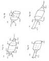
- FIG. 1A-1Dillustrates balloons suitable to implement embodiments of the present disclosure.
- FIG. 2A-28illustrates embodiments of the present disclosure suitable to remove objects from a body.
- FIG. 3A-3Cillustrates tools of the present disclosure.
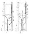
- FIGS. 4A-4Fillustrates embodiments of the present disclosure removing a stent from an anatomical pathway.
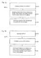
- FIGS. 5A-58shows block diagrams of embodiments of the present disclosure.
- FIG. 6illustrates a deployed receiving socket
- a socketis deployed from a catheter, the socket being conically shaped and transitioning from an annularly shaped distal lip of the balloon to a lumen of the catheter.
- an inflatable balloonis provided on a distal end of a catheter, a surface of the balloon defining a socket inwardly sloped toward a lumen of the catheter.
- attachment and manipulation toolsfor moving an object through the socket and into the lumen of the catheter.
- Various embodiments of the present disclosurealso include reducing a diameter of a stent while the stent is moved through the socket.
- Stentsinclude metal and plastic structures forming a single or multiple tubes.
- Various stentsinclude matrices of thin wires woven, braided, or connected to define circular or elliptical tubes.
- Metal stentscan be constructed of NiTi alloy or alloys of stainless steel, among other metals.
- Stentscan also be covered with a polymeric material as disclosed by Goodwin, et al. (U.S. Pat. No. 6,808,533) or coated for purposes of containing and/or exuding a drug, as disclosed by Schaldach, et al. (U.S. Pat. No. 6,796,998).
- Placement of stents in blood pathwaysincludes placement in arteries. Placement of stents in air pathways includes placement in tracheal and bronchial airways. Placement of stents in waste pathways includes placement in the urethra. Stents can also be placed in various ducts and in locations to support surrounding anatomical systems and structures or deliver drugs, among other things. However, placement of stents, as well as other objects, in the body is not so limited.
- Stentswhile being placed, or after placement, can cause undesirable effects harmful to the body in which it is located. Such harmful effects can be caused by normal function, abnormal function, or malfunction of the stent and/or the delivery system or other part or device used within the body. Stents can collapse inward, fail to deploy as intended, and strain and/or break anatomical structures. Moreover, a stent may prove to be insufficient to adequately treat a problem that had instigated the delivery of a stent. Furthermore, tissues surrounding the stent may be harmed by the presence of the stent. An immune system of a body may attack a stent and its associated materials causing problems.
- Balloonscan be made from various polymers, as well as other materials.
- Polymeric balloonscan be made from thermoplastic and/or thermoset materials. Many methods of balloon forming are known in the art.
- balloonscan be made by extruding polymeric material into tube form, the tube including a lumen.
- An extruded tubecan be placed in a mold, an inside surface of the mold defining a negative of the exterior of a balloon.
- the lumen of the ballooncan be pressurized and the mold can be heated, the heat transferring to the tube. By combination of the pressure and heat, the tube can expand outwardly to the inside surface of the mold.
- the moldcan then be cooled, which in turn can cool the polymeric material.
- Additional balloon blowing tools and methodsare herein incorporated by reference, as described by Mahoney, et al. (U.S. Pat. No. 6,863,856).
- FIG. 1Aillustrates an embodiment of a balloon.
- the balloon 100includes a first opening 101 - 1 , defined by the end of a first tail 102 - 1 .
- a tail of a balloonrefers to a sectional length of a balloon on an end of the balloon. Balloons can include two tails.
- the balloon 100also includes a first seam 103 - 1 , adjacent to a first transition section 104 - 1 .
- An outer diameter of the first transition section 104 - 1can be approximately equal to the outer diameter of the first tail 102 - 1 at the first seam 103 - 1 .
- the outer diameter of the first transition sectioncan change along a sectional length of the balloon 100 .
- the respective outer surfaces of the first transition section 104 - 1 and the second transition section 108 - 1can take the form of a cone, the cone not having a pointed end.
- different shapesare contemplated for transition sections 104 - 1 and 108 - 1 , including but not limited to sections of cones.
- various embodiments of the present disclosurecan include only one transition section.
- the balloon 100can include a middle section 106 - 1 , located between a second seam 105 - 1 and a third seam 107 - 1 .
- the middle section 106 - 1can have an approximately constant outer diameter along its sectional length, however, various embodiments of the present disclosure are not so limited.
- the balloon 100can also include a second transition section 108 - 1 .
- the outer diameter of the second transition sectioncan change between the third seam 107 - 1 and a fourth seam 109 - 1 .
- the ballooncan also include a second tail 110 - 1 , one end of which can define a second opening 111 - 1 .
- the embodiment of a balloon in FIG. 1Aillustrates a balloon 100 that is substantially hollow.
- Balloons of different embodimentshave various wall thicknesses. Wall thicknesses can range from 0.001′′ to 0.010′′ (0.0254 mm to 0.254 mm), but other wall thicknesses, including larger and smaller wall thickness than the dimensions given herein, are suitable depending on various configurations, including but not limited to the balloon material used.
- the wall thickness of the balloon 100can be different for different parts of the balloon 100 .
- some portionscan have a wall thickness smaller than the second transition section 108 - 1 , which in some embodiments could correspond to a flexible joint between the middle section 106 - 1 and the second transition section 108 - 1 and/or a reinforced second transition section 108 - 1 that is more resistant to tearing and/or punctures.
- Varying wall thickness in balloonscan be accomplished by several processes, including dual stage balloon blowing (blowing different portions of the balloon at different times) and processing the material between blowing cycles, and/or using an extruded tube with varying wall thicknesses (whether the tube is extruded with a varying wall thickness or the extruded tube is necked after extrusion).
- Reinforcement of balloon sectionscan also be accomplished by several processes.
- One processincludes adhering one or more additional layers to the balloon material. This can be accomplished after a balloon is blown, by adhering a layer to the balloon with an adhesive agent, solvent, applied heat to weld the two materials together, or another process known in the art.
- layerscan be added to the balloon wall by placing the additional layers within the balloon mold before the balloon is blown, such that the layers contact the balloon as the balloon is being blown and in the process attach to the balloon wall. Attachment in this way can be accomplished by heat bonding between the two materials, the heat provided by the heated mold in which the blowing balloon is placed.
- a reinforcement layercan be added to a part of or to an entire balloon surface.
- a reinforcement layercan be added to a portion of the second transition section 108 - 1 , the first transition section 104 - 1 , and/or the middle section 106 - 1 .
- a layer added to a ballooncan be a layer of polymeric material, and/or metal.
- struts, wires, bars, tubes, and other partscan also be added to the balloon material and the various sections of a balloon in the same way that a layer is added, as discussed above.
- FIG. 1Billustrates an embodiment of a partially inverted balloon.
- the partially inverted balloon 120can be formed from balloon 100 of FIG. 1A by inverting a portion of the balloon 100 , but various processes for making a partially inverted balloon 120 are not so limited.
- a second opening 111 - 1 of the balloon 100 of FIG. 1Acan be turned inward, as if to be turned inside-out.
- This inversioncan be continued to include the whole of the second tail 110 - 1 , the fourth seam 109 - 1 , and the second transition section 108 - 1 , stopping at or before the third seam 107 - 1 of the balloon 100 of FIG. 1A .
- the second tail 110 - 1 of the balloon 100can become the second tail 110 - 2 of the partially inverted balloon 120 .
- the second opening 111 - 1 of the balloon 100can become the second opening 111 - 2 of the partially inverted balloon 120 , which in the embodiment illustrated in FIG. 1B opens to the inside of the inverted balloon 120 .
- a ballooncould be blown with a suitable shape not needing inversion to accomplish the same as a partially inverted balloon.
- a ballooncan be blown which when mounted on a catheter includes a surface that defines a socket that is inwardly sloped toward a lumen of the catheter, the balloon not in an inverted configuration.
- object and/or stent capture of the present disclosurecan be accomplished without a balloon.
- different materialscan be employed to create shapes suitable to reduce the diameter of a stent such that the stent can be removed from an anatomical passageway.
- FIG. 1Cillustrates an embodiment of a partially inverted balloon 135 mounted on a catheter shaft 131 - 3 .
- Balloonscan be mounted on catheter shafts in various ways.
- a partially inverted balloonsuch as the partially inverted balloon 120 of FIG. 1B
- the catheter shaft-partially inverted balloon assembly 130 of FIG. 1Ccan be made from the partially inverted balloon 120 of FIG. 1B by moving an end of a catheter shaft 131 - 3 through a first opening 101 - 2 , through the first tail 102 - 2 , and through the second opening 111 - 2 .
- the end of the catheter shaft 131 - 3can be moved past the forth seam 109 - 2 , however, some embodiments of the present disclosure locate the end of the catheter shaft 131 - 3 between the second opening 111 - 2 and the forth seam 109 - 2 .
- the balloon 135can include a surface that defines a socket that is inwardly sloped toward the catheter shaft 131 - 3 , which can include a lumen.
- this inwardly sloped surfacecan correspond to a first transition section 104 - 1 or a second transition section 110 - 1 of the balloon 100 illustrated in FIG. 1A if the balloon 100 is partially inverted or processed.
- various embodiments of the present disclosureare not so limited.
- a surface of the balloon 135can define a funnel shaped cavity that transitions from an annularly shaped distal end of the balloon 135 to a lumen of a catheter shaft 131 - 3 .
- this funnel shaped cavity defined by a surfacecan correspond to a first transition section 104 - 1 or a second transition section 110 - 1 of the balloon 100 illustrated in FIG. 1A if the balloon 100 is partially inverted or processed.
- various embodiments of the present disclosureare not so limited.
- a surface of the balloon 135can define a socket that is inwardly sloped toward a lumen of the catheter shaft 131 - 3 .
- the surface defining the socketcan include a section where the surface is linear, or substantially linear, that is, linear except for imperfections in the material and/or slight bowing from under or over inflation.
- a substantially linear section of a surfacecan, in some embodiments, correspond to a first transition section 104 - 1 or a second transition section 110 - 1 of the balloon 100 illustrated in FIG. 1A if the balloon 100 is partially inverted or similarly processed.
- the socketcan be conically shaped.
- conically shapedrefers to a shape that takes the form of all or part of a cone.
- a surface that defines a socket that is conically shapedcan take the form of a cone, or the negative of a cone, but does not include the pointed top.
- a surface of a ballooncan form a conical shape, including a socket, despite slight bowing in the sides due to under or over inflation and/or imperfections in the material.
- the balloon 135 of FIG. 1Ccan include a surface that defines a socket inwardly sloped toward the catheter shaft 131 - 3 wherein the socket is conically shaped and the surface transitions from an annularly shaped lip 136 - 3 of the balloon 135 to an end of the catheter shaft 131 - 3 .
- the surface defining the conically shaped socketcan, in some embodiments, correspond to the first transition section 104 - 1 or a second transition section 110 - 1 of the balloon 100 illustrated in FIG. 1A if the balloon 100 is partially inverted or similarly processed.
- FIG. 1Dillustrates an embodiment of a balloon being inverted while partially on a catheter shaft.
- the balloon of FIG. 1Dcan be the balloon 100 of FIG. 1A .
- an end of a catheter shaft 141 - 4can be moved through the second opening 111 - 4 and located between the forth seam 109 - 4 and the second opening 111 - 4 , the second opening 111 - 4 , and the forth seam 109 - 4 corresponding to the second opening 111 - 1 and the forth seam 109 - 1 of FIG. 1A , however, the present disclosure is not so limited.
- the second tail 110 - 4can be attached to the catheter shaft.
- Attachmentcan be accomplished by various methods, including applying heat (generated by any source, including RF, and thermocouples) and/or pressure to the outer surface of the second tail 110 - 4 .
- the second tail 110 - 4can also be attached to the catheter shaft 141 - 4 by any other adhering means, including but not limited to, solvent bonding, adhesive bonding (including but not limited to use of epoxies and cyanoacrylates) and/or sonic welding.
- the balloon materialcan be brought through the first opening 101 - 4 such that the first opening 101 - 4 and the first tail 102 - 4 are over the catheter shaft 141 - 4 .
- the result of the balloon inversion shown in FIG. 1Dcan be the same as the result illustrated in FIG. 1C .
- the inside of a balloon mounted on a catheter shaftcan be isolated such that fluids and gasses between the balloon material and the catheter shaft cannot escape, nor can gasses or fluids outside of the volume between the balloon and the catheter shaft get within this volume once sealed, except by a valve and/or some inflation mechanism.
- a section of a catheter shaft over which a balloon will be placedcan be cut to tap into a second lumen of the catheter shaft, and this same lumen can be sealed on the distal end (such as by a heat seal or a plug of material), such that if gas and/or fluid was provided through the second lumen on the proximal end of the catheter shaft, a balloon mounted on the catheter shaft would inflate.
- Balloon tails and other partscan be attached and/or adhered to accomplish sealing, as discussed herein.
- Balloons of the present disclosurecan be made from a variety of polymers, polymer hybrids, as well as from other types of materials. Materials of various balloons of the present disclosure can have elastic or inelastic properties. Balloons can be made from compliant, semi-compliant, and/or non-compliant polymeric materials. In different embodiments of the present disclosure, different advantages can be sought by use of polymers with different properties. For example, some semi-compliant and non-compliant balloons, as they are known in the art, can retain a rigid shape once inflated. In contrast, compliant balloons will continue to increase in size the greater the pressure is produced within the balloon.
- a balloon formed from semi-compliant or non-compliant polymeric materials, mounted on a catheter shaft with a central lumencan include a surface that defines a funnel shaped socket that is inwardly sloped toward the central lumen.
- an object moved through the funnel shaped socketcan apply force and torque to the balloon surface, but the balloon surface will not deflect and the structure defined by the inflated balloon will remain despite the applied force and torque, in-part because of the properties of the semi-complaint or non-compliant polymeric balloon material.
- semi-compliant and non-compliant balloonscan form shapes that compliant balloons cannot, especially fine features, sharp edges, fine lips, and sharp ridges.
- Polymeric material that can exhibit semi-compliant or non-compliant properties in certain configurationsinclude, but are not limited to, poly(ethylene terphthalate), polyamides, polyimide, polyphenylene sulfides, thermoplastic polyimide, polyesters, polycarbonates, poly vinyl chloride, polypropylene and polyurethanes.
- Semi-compliant and non-compliant balloon materialscan be more brittle in some circumstances and in some circumstances harder to process as compared to compliant balloon materials. This is due in part to the inelastic properties that some semi-compliant and non-compliant materials exhibit in certain configurations.
- several techniquescan be employed to allow semi-compliant and non-compliant materials to be processed as compliant materials, including temporarily changing the elastic properties of the material. For example, semi-compliant and non-compliant materials can be annealed before and/or after manipulation and processing. Also, the temperature at which semi-compliant and non-compliant materials are processed and manipulated can be increased and later lowered when the processing and manipulation is complete.
- the semi-compliant and non-compliant materialscan be exposed to a diluted solvent, then processed and manipulated, then dried to remove the solution and the solvent.
- semi-compliant and non-compliant materialscan be processed and manipulated, including temporarily imparting elastic properties to the materials, to take the desired form.
- Temporarily or permanently changing the elastic properties of a materialcan be useful for several purposes, including but not limited to, moving a tail of a balloon onto and/or over a catheter shaft, or over another object, wherein the balloon is made from a non-compliant material and an inner diameter of the balloon tail is smaller than an outer diameter of the catheter shaft at a resting state.
- Catheterscan include elongated tubes made from various materials, including polymers and metals. Catheters can have one or more lumens. Lumens, as they are known in the art, can include a passageway within a catheter that runs some distance of the catheter, and in some cases can run the entire length of the catheter, having an opening on each end. However, a lumen can also be closed, sealed, plugged, and/or transitioned into another feature, and thus in these ways, among other ways, lumens may not run the entire length of a catheter in all embodiments. Polymeric catheters, with one or more lumens, can be extruded, as is known in the art.
- FIG. 2Aillustrates an embodiment of the present disclosure.
- FIG. 2Ashows a medical device 200 .
- an uninflated balloon 203 - 1is mounted on a distal end 202 - 1 of a catheter shaft 201 - 1 .
- An access and control assembly 210 - 1is attached to the proximal end of the catheter shaft 201 - 1 .
- the access and control assembly 210 - 1can provide access to one or more lumens of the catheter shaft, including but not limited to a central lumen and an inflation lumen.
- the access and control assembly 210 - 1can also provide an interface for electrical and mechanical devices, accessories, peripherals, luers, signals, fluids, and tools.
- the embodiment of the access and control assembly 210 - 1 illustratedincludes a luer attachment 205 - 1 and conductor connection 206 - 1 , but various embodiments of the present disclosure are not so limited.
- the inflation control device 211 - 1can be any means and/or mechanism known in the art for inflating balloons, providing fluids, and/or controlling pressure, including but not limited to syringes, plungers, and pumps.
- the inflation control device 211 - 1can be in communication with an inflation lumen, the inflation lumen also in communication with the uninflated balloon 203 - 1 , such that fluids provided by the inflation control device 211 - 1 can flow through the inflation lumen and into the uninflated balloon 203 - 1 , however, various embodiments of the present disclosure are not so limited.
- the embodiment shown in FIG. 2Acan be employed in various ways to remove objects, including natural and artificial objects, from a body.
- the medical device 200 illustrated in FIG. 2Acould be used to remove objects from various areas of the body, but is particularly suited to remove objects from anatomical passageways, including but limited to pathways of the circulatory system, pathways of the respiratory system, and pathways of the digestive and gastrointestinal system.
- the distal end 202 - 1 of the medical device 200can be feed through an incision in a femoral artery and run over a guide wire to a vasculature associated with the heart, such as a coronary artery.
- the uninflated balloon 203 - 1can be located proximal to an object, such as a stent that has previously been deployed in the coronary artery.
- the uninflated balloon 203 - 1can then be inflated by inflation means 211 - 1 .
- various embodiments of the present disclosureare not so limited.
- Embodiments of the present disclosurecan be introduced into a body by various methods.
- a portion of the medical device 200can be inserted through the mouth to access objects in the throat, esophageal, trachea, bronchia, and stomach areas, as well as other areas of the body.
- a portion of the medical device 200can be introduced into the circulatory system of a body and navigated through the pathways therein.
- accesscan be gained to coronary arties through a hole in the femoral artery, wherein the medical device 200 is routed to the arteries of the heart.
- Introduction, navigation, and use of the medical device 200can be aided by use of an introducer.
- Embodiments of the present disclosurecan also employ any methods and/or devices, as are known in the art, for introduction and use within the body.
- FIG. 2Billustrates an embodiment of the present disclosure.
- FIG. 2Bshows an inflated medical device 250 .
- the result of inflationis illustrated in FIG. 2B , as the inflated medical device 250 .
- tools, wires, scopes, fluids, and/or signalscan be introduced through, or accessed from, the access and control assembly 210 - 1 and 210 - 2 .
- the access and control assembly 210 - 2can provide access to a central lumen of a catheter shaft 201 - 2 , the central lumen extending to the distal end 202 - 2 .
- toolscan be routed through the access and control assembly 210 - 2 , through the catheter shaft 201 - 2 , past the inflated balloon 203 - 2 , and through the distal end 202 - 2 .
- a gasket or other sealing meanscan be provided in the access and control assembly 210 - 2 , or at other locations of the medical device 200 and/or of the inflated medical device 250 , to prevent bodily fluids from escaping the body through the inflated medical device 250 , while also allowing access for tools and other parts to the inside of the body.
- various embodiments of the present disclosureare not so limited.
- Guide wirescan assist in navigation and location in and through anatomical pathways.
- the medical device 200can be routed over a guide wire by inserting the guide wire into a distal opening of the central lumen 202 - 1 or into the access and control assembly 210 - 1 .
- various embodiments of the present disclosureare not so limited.
- Various embodiments of the present disclosurecan employ a deflecting tip and/or a shaft that can be turned and/or articulated to navigate through anatomical pathways.
- various embodiments of the present disclosurecan also contain marker bands, antennas and/or radio opaque materials, as well as other imaging and location tools known in the art, to assist with navigation and location.
- MRI and other imaging and location systemscan be used with various embodiments of the present disclosure.
- the inflated balloon 203 - 2can include a surface that defines a socket that is inwardly sloped toward a lumen of the catheter shaft 201 - 1 .
- the socketcan be conically shaped and the surface can transition from an annularly shaped distal lip of the balloon to a lumen of the catheter shaft 201 - 1 .
- a surface of the balloon 203 - 2can define a funnel shaped cavity that transitions from an annularly shaped distal end of the balloon 203 - 2 to a lumen of a catheter shaft 201 - 2 .
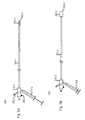
- FIG. 3Aillustrates an embodiment of the present disclosure.
- FIG. 3Ashows an attachment tool 300 - 1 .
- the attachment tool 300 - 1includes a shaft 310 - 1 having a lumen 311 - 1 , the lumen 311 - 1 accommodating a rod 317 - 1 .
- the rod 317 - 1is attached to a plunger 312 - 1 and a head 320 - 1 .
- the shaft 310 - 1also includes a proximal end of the shaft 314 - 1 .
- arms 321 - 1 and 322 - 1can be attached to the shaft 310 - 1 .
- FIG. 3Aalso shows a spring 313 - 1 on the attachment tool 300 - 1 .
- the rod 317 - 1runs through the center of the spring 313 - 1 .
- the spring 313 - 1can apply force to both the proximal end of the shaft 314 - 1 and the plunger 312 - 1 .
- increasing the distance between the proximal end of the shaft 314 - 1 and the plunger 312 - 1can cause the head 320 - 1 to push the arms 321 - 1 and 322 - 1 outward, in a deployed position.
- attachment tool 300 - 1can include any number of arms, such as arms 321 - 1 and 322 - 1 . Although two arms are illustrated in the embodiment shown in FIG. 3A , various embodiments can include four, six, or any number of arms. Arms can be configured in various ways. For example, an attachment tool with four arms can have the four arms arranged ninety degrees apart, each attached to the distal end of the shaft 310 - 1 . However, various attachment tools of the present disclosure are not so limited.
- FIG. 3Billustrates an embodiment of the present disclosure.
- FIG. 3Bshows an attachment tool 300 - 2 .
- the distance between a distal end of the shaft 314 - 2 and a plunger 312 - 2has been reduced relative to the embodiment of the attachment tool 300 - 1 illustrated in FIG. 3A .
- a head 320 - 2has moved away from the distal end of the shaft 318 - 2 , relieving pressure on the arms 321 - 2 and 322 - 2 , allowing the arms 321 - 2 and 322 - 2 to straighten in a undeployed configuration.
- a profile of the distal end of the attachment tool 300 - 2is reduced, allowing the attachment tool 300 - 2 to fit and navigate through smaller spaces, such as a lumen of a catheter, as compared to an attachment tool 300 - 1 in a deployed position.
- various attachment tools of the present disclosureare not so limited.
- FIG. 3Cillustrates an embodiment of the present disclosure.
- FIG. 3Cshows a view of arm 321 - 3 , and in some embodiments can resemble attachment arm 321 - 2 or 321 - 1 .
- the shaft 323 - 3 of arm 321 - 3is connected to a hook 324 - 3 .
- the hook 324 - 3can accommodate, catch, latch onto, or hook a strut or a part of a stent, or a part of an object.
- any method or meansincludes but is not limited to hooking, grasping, latching, catching, attaching and clasping onto an object.
- the hook 324 - 3can be replaced with an articulated clasp.
- an arm of an attachment toolcan include an adhesive to attach to an object.
- an attachment toolcan thread material, such as nylon, such that the material attaches to a stent or some other object.
- a magnetic toolcan also act on an object and/or a stent.
- various embodiments of the present disclosureare not so limited.
- FIG. 4Aillustrates an embodiment of the present disclosure in a cut-away view.
- FIG. 4Ashows a distal end of a stent capture device 400 - 1 .
- the distal end of the stent capture device 400 - 1has been located proximal to a stent 450 - 1
- both the distal end of the stent capture device 400 - 1 and the stent 450 - 1are located within arterial walls 471 - 1 and 472 - 1 .
- a balloon 410 - 1attached to a shaft 403 - 1 , is shown as inflated.
- An inflation lumencan be located within the walls of a shaft 403 - 1 to provide fluids to inflate the balloon 410 - 1 .
- the distal end of the stent capture device 400 - 1can be navigated to a location proximal to a stent 450 - 1 with an uninflated balloon, then when positioned, the balloon can be inflated.
- Balloonscan be inflated to various diameters in different embodiments of the present disclosure. For example, an outer surface of the balloon 410 - 1 can be inflated to an outer diameter that is larger than an inner diameter of the arterial walls 471 - 1 and 472 - 1 before the inflation of the balloon 410 - 1 .
- the outer diameter of an inflated balloon being larger than the inner diameter of arterial walls, thus increasing the inner diameter of the arterial walls,can serve multiple purposes, including but not limited to anchoring and/or stabilizing the distal end of the stent capture device 400 - 1 and/or loosening the stent 450 - 1 from the arterials walls 471 - 1 and 472 - 1 .
- the balloon 410 - 1is made from non-compliant polymeric materials.
- a balloon 410 - 1can include a surface that defines a socket that is inwardly sloped toward a central lumen 420 - 1 .
- This surfacecan be, in various embodiments, the surface of the balloon 410 - 1 between an annularly shaped lip 490 - 1 , or a plane formed by the annularly shaped lip 490 - 1 , and a distal opening 411 - 1 of the central lumen 420 - 1 , or a plane formed by the distal opening 411 - 1 of the central lumen 420 - 1 .
- the surface of the balloon 410 - 1is linear between the annularly shaped lip 490 - 1 and the distal opening 411 - 1 of the central lumen 420 - 1 , however, various embodiments of the present disclosure are not so limited. In various embodiments of the present disclosure, this inwardly sloped surface can correspond to the first transition section 104 - 1 or a second transition section 110 - 1 of the balloon 100 illustrated in FIG. 1A if the balloon 100 is partially inverted or processed.
- a balloon 410 - 1can include a surface that defines a socket that is inwardly sloped toward a central lumen 420 - 1 .
- This surfacecan be, in various embodiments, the surface of the balloon 410 - 1 between an annularly shaped lip 490 - 1 , or a plane formed by the annularly shaped lip 490 - 1 , and a distal opening 411 - 1 of the central lumen 420 - 1 , or a plane formed by the distal opening 411 - 1 of the central lumen 420 - 1 .
- this socketcan be conically shaped between the annularly shaped lip 490 - 1 and the distal opening 411 - 1 of the central lumen 420 - 1 , or the respective planes formed by each.
- various parts and socketscan have specific and/or relative dimensions.
- the distance between a distal opening 411 - 1 of the central lumen 420 - 1 and an annularly shaped lip 490 - 1 , or the distance between the corresponding planes formed by eachcan be greater than or less than other dimensions of the stent capture device 400 - 1 , including but not limited to an outer diameter of the balloon 410 - 1 when the balloon 410 - 1 is inflated, an inner diameter of the central lumen 420 - 1 , an outer diameter of the shaft 403 - 1 , a length of a surface of the balloon 410 - 1 when inflated, or a distance between tails of the balloon 410 - 1 .
- a balloon tail 491 - 1 of balloon 410 - 1is contacting a surface of the shaft 403 - 1 .
- the tail 491 - 1as well as other parts of the balloon 410 - 1 , can be attached to the shaft 403 - 1 by thermal weld, adhesive, solvent, and/or pressure, among others.
- the tail 491 - 1can alternatively be attached to an inside surface of the central lumen 420 - 1 .
- the balloon 410 - 1 and/or the shaft 403 - 1can be shaped, processed, or modified to make a smooth surface transition from the balloon 410 - 1 to the shaft 403 - 1 , including adding material and/or adding a fillet.
- a seamless transitioncan be experienced by an object, such as a stent, moving through a socket formed by an inwardly sloped surface of the balloon 410 - 1 and into the central lumen 420 - 1 .
- FIG. 4Billustrates an embodiment of the present disclosure in a cut-away view.
- FIG. 4Bshows a distal end of a stent capture device 400 - 2 .
- an attachment tool 430 - 2can been introduced, and routed through a central lumen 420 - 2 and a distal opening 411 - 2 of a shaft 403 - 2 .
- the attachment tool 430 - 2can be deployed and arms 431 - 2 and 432 - 2 can each hook stent struts 451 - 2 and 452 - 2 , respectively.
- the attachment tool illustrated in FIG. 4Bcan include embodiments of the attachment tools illustrated in FIGS.
- the arms 431 - 2 and 432 - 2 of the attachment tool 430 - 2can be moved between the stent 450 - 2 and the arterial walls 471 - 2 and 472 - 2 by first deploying the arms 431 - 2 and 432 - 2 , pushing the attachment tool 430 - 2 in the distal direction, and then pulling the attachment tool 430 - 2 in the proximal direction such that the hooks set in struts of the stent 450 - 2 from the outside of the stent.
- articulating clasping meanscan be provided on the ends of arms 431 - 2 and 432 - 2 and can attach to struts 451 - 2 and 452 - 2 without dragging over the stent 450 - 2 , or hooks orientated in a different way could be dragged along a inside surface 455 - 2 of the stent 450 - 2 to set in stent struts 451 - 2 and 452 - 2 from the inside of the stent, as opposed to dragging along a outside surface 456 - 2 of the stent, as explained above.
- These and other means and mechanismsare contemplated in the present disclosure for controlling and/or moving a stent, however, various embodiments of the present disclosure are not so limited.
- the central lumen 420 - 2 of the stent capture device 400 - 2can serve multiple functions, including accommodating scopes, signal conductors, guide wires, tools, attachment tools, navigation tools, imaging tools, and nets, among other things. Moreover, the central lumen 420 - 2 can accommodate captured objects and tissues. For example, stents can be drawn into the central lumen 420 - 2 for removal from the body. Also, the central lumen 420 - 2 can allow fluid flow within the shaft 403 - 2 , including bodily fluids such as blood, which can be particularly useful for allowing blood to flow through an anatomical pathway even when a balloon is deployed in the pathway. This can be aided by porting in the shaft 403 - 2 . However, various embodiments of the present disclosure are not so limited.
- FIG. 4Cillustrates an embodiment of the present disclosure in a cut-away view.
- FIG. 4Cshows a distal end of a stent capture device 400 - 3 .
- FIG. 4Cillustrates an embodiment of the present disclosure in a cut-away view.
- FIG. 4Cshows a distal end of a stent capture device 400 - 3 .
- FIG. 4Ccontinues from the non-limiting example presented in relation to FIG.
- the distance between the stent 450 - 3 and distal end of stent capture device 400 - 3can been closed, by either advancing the distal end of stent capture device 400 - 3 toward the stent 450 - 3 or by pulling the stent 450 - 3 toward and into the distal end of stent capture device 400 - 3 with the attachment tool 430 - 3 , or by a combination of the two, such that the stent 450 - 3 is drawn into a socket defined by a surface of the balloon 410 - 3 . As illustrated in FIG.
- the outer diameter of the stent 450 - 3can reduced as the stent 450 - 3 is moved along a surface of the balloon 410 - 3 .
- an outer profilesuch as the outer diameter of a stent, can be reduced by moving the stent along a surface, the surface defining a socket inwardly sloped.
- the stent 450 - 3can be reduced in diameter by moving the stent 450 - 3 through a socket defined by a surface of the balloon 410 - 3 causing relative movement between the stent and the socket.
- various embodiments of the present disclosureare not so limited.
- the struts of the stent 450 - 3can compact uniformly, or the struts of stent 450 - 3 can compact in a non-uniform manner.
- the stent 450 - 3can collapse inward, where the stent 450 - 3 no longer resembles a circle or has outer curved surfaces.
- the stent 450 - 3can even break, including but not limited to strut fracture, bending, unbraiding and/or unweaving. In any case, any reduction in any profile and/or dimension of the stent 450 - 3 is contemplated in the present disclosure, including breaking of the stent 450 - 3 .
- FIG. 4Dillustrates an embodiment of the present disclosure in a cut-away view.
- FIG. 4Dshows a distal end of a stent capture device 400 - 4 .
- a stent 450 - 4can be drawn into a central lumen 420 - 4 of the stent capture device 400 - 4 .
- the stent 450 - 4can be pulled further into the stent capture device 400 - 4 by attachment tool 430 - 4 .
- the stent 450 - 4can be reduced in diameter by moving the stent 450 - 4 through a socket defined by a surface of the balloon 410 - 4 .
- the central lumen 420 - 4can be defined by an inner surface 440 - 4 of the catheter shaft 403 - 4 .
- the central lumen 420 - 4can include a consistent inner diameter along its length, or its inner diameter can change along its length.
- the central lumen 420 - 4can contain coatings or materials different from materials of the shaft 403 - 4 .
- FIG. 4Eillustrates an embodiment of the present disclosure in a cut-away view.
- FIG. 4Eshows a distal end of a stent capture device 400 - 5 .
- a stent 450 - 5can be contained within the central lumen 420 - 5 of the stent capture device 400 - 5 .
- the stent 450 - 5can be removed from a body by removing the stent capture device 400 - 5 .
- FIG. 4Fillustrates an embodiment of the present disclosure in a cut-away view.
- FIG. 4Fshows a distal end of a stent capture device 400 - 6 .
- the balloon 410 - 6is partially deflated.
- the stent capture device 400 - 6can have a smaller profile, including a smaller outer diameter, after the balloon 410 - 6 has been deflated.
- various embodiments of the present disclosureare not so limited.
- a sheath on the shaft 403 - 6can be slid over the balloon 410 - 6 , which can reduce the profile of the balloon 410 - 6 and/or insulate the balloon 410 - 6 .
- the outer diameter of the inflated balloon 410is greater than the outer diameter of the shaft 403 . In some embodiments of the present disclosure, this can allow a stent capture device 400 to navigate through pathways that are narrower than the balloon 410 when inflated. Also, in various embodiments, once a balloon 410 is inflated, a stent capture device can capture a stent 450 that is larger in diameter than the shaft 403 by moving the stent 450 into the central lumen 420 - 5 , even though the stent 450 had a larger outer profile than the inner diameter of the central lumen 420 - 5 , as illustrated in FIGS. 4A-4E .
- the balloon 410can be deflated and the stent capture device 400 and the stent 450 can be removed from the anatomical pathway.
- a profile of a stent capture device 400can be decreased, allowing the stent capture device 400 to be withdrawn easily and removed from the body.
- various embodiments of the present disclosureare not so limited.
- componentscan be coated or treated to change the properties of the components.
- a surface of a ballooncan be coated to provide hydrophilic or hydrophobic properties.
- components, such as a ballooncan be coated to alter the coefficient of friction between the surface of the balloon and another material.
- componentscan be coated and/or processed to change the lubriciousness of the components.
- a portcan be made in a catheter shaft, the port allowing fluid to flow from the outside of the catheter shaft, through the port and into a lumen of the catheter.
- a portcan be made in the shaft 403 - 2 , proximal to the balloon 410 - 2 , for example.
- fluidsuch as blood
- bloodcan flow from the proximal side of the balloon 410 - 2 , into the central lumen 420 - 2 , and through the distal opening 411 - 2 of the central lumen 420 - 2 .
- blood, and/or other fluidscan flow in the anatomical passageway even when the balloon 410 - 2 is inflated.
- various embodiments of the present disclosureare not so limited.
- Embodiments of the present disclosurecan also include use of a sheath over a catheter shaft and over deployable components, including an uninflated balloon.
- a sheath slid over a ballooncan reduce the profile of a balloon, force fluid out of the balloon, and insulate the balloon, among other things.
- Various embodiments of the present disclosureinclude attaching a balloon tail to the inside of a lumen of a catheter, and thus attachment of balloons is not limited to outer surfaces of a catheter or catheter shaft.
- a smoother transition between a catheter lumen and a surface of an inflated balloon defining a socket inwardly sloped toward the lumencan be formed, as compared to various embodiments where balloon tails are only attached to the outer surfaces of a catheter shaft.
- a deployable receiving socketcan include a balloon, but the present disclosure is not so limited.
- the deployable receiving socketcan include metal or polymer arms, each arm connected by mesh or other flexible material configuration and the proximal end of each arm can be attached to a catheter, the catheter including a lumen.
- the meshcould be made from metal or polymers, and the flexible material can include but is not limited to a polymer sheet.
- the polymer layer and/or meshin an undeployed position, the polymer layer and/or mesh can be folded under and/or in-between the arms.
- the armswhen in a deployed position, can hinge at their proximal ends while the distal end of each arm projects outward, unfolding the mesh or polymer sheet between the arms and forming a receiving socket that is sloped inwardly towards a lumen of the catheter.
- FIG. 6illustrates a balloon 635 mounted on a catheter shaft 631 , the balloon 635 deploying a receiving socket that comprises a plurality of arms 690 connected with flexible material 694 , the flexible material 694 attached to the balloon 635 .
- the balloon 410can be made and formed from different materials and by different methods.
- the balloon 410can be a polymeric material, and/or multiple polymeric materials.
- the balloon 410can be made from a non-compliant polymeric material.
- the balloon 410can be made from a semi-compliant polymeric material.
- the balloon 410can be made from a compliant polymeric material.
- the present disclosureis not so limited.
- a surface of the ballooncould define a socket that has a curved shape.
- Other shapesare also contemplated within the present disclosure.
- FIG. 5Ashows a block diagram of an embodiment of the present disclosure.
- FIG. 5Ais a block diagram representing a method for capturing a stent.
- the methodincludes inflating a balloon on a catheter.
- the ballooncan be attached to a distal end of the catheter.
- the cathetercan also be introduced into an anatomical passageway of a body, such as an artery.
- the ballooncan also be located proximal to an object in the body, including natural and/or artificial objects, such as a stent.
- a balloon inflated in connection with the method of block 510can include an embodiment of a balloon from FIGS. 1A-1D , among others.
- a surface of the ballooncan define a socket that is inwardly sloped toward a lumen of the catheter. Inflating the balloon can also expand the inner diameter of the anatomical passageway by an outer surface of the balloon contacting the inner walls of the anatomical passageway.
- various embodiments of the present disclosureare not so limited.
- the methodincludes engaging a stent with a socket defined by a surface of the balloon, the surface inwardly sloped toward a lumen of the catheter.
- engaging a stent with a socketcan include pulling the stent toward the inflated balloon and into the socket defined by a surface of the balloon.
- Engaging the stent with the socket of the ballooncan include pulling the stent toward the socket with a tool, such as an attachment tool.
- a toolsuch as an attachment tool.
- the methodincludes retracting a portion of the stent through the socket and into the lumen.
- retracting a portion of the stent through the socketcan include reducing a profile of the stent as the stent is moved through the socket defined by a surface of the balloon.
- the stentcan be retracted through the socket and into the lumen by using an attachment tool, such as the embodiments shown in FIGS. 3A-3C .
- an attachment toolsuch as the embodiments shown in FIGS. 3A-3C .
- various embodiments of the present disclosureare not so limited.
- FIG. 5Bshows a block diagram of an embodiment of the present disclosure.
- FIG. 5Bis a block diagram representing a method for making a catheter.
- the methodincludes forming a balloon.
- Forming a ballooncan include blow molding a balloon, however the present disclosure is not so limited.
- the methodincludes inverting a portion of the balloon.
- invertingcan include turning a portion of the balloon inside-out, such that a surface of the balloon that was an outside surface of the balloon becomes an outside surface.
- FIGS. 1A-1DEmbodiments of balloons, before and after inversion, are shown in FIGS. 1A-1D , however, various embodiments of the present disclosure are not so limited. Inversion of a portion of the balloon can be done before the balloon is placed on the catheter, and/or after a portion of the balloon, such as a tail section, has been attached or placed on a catheter shaft. However, the present disclosure is not so limited.
- the methodincludes attaching the balloon to a catheter such that a surface of the balloon defines a socket that is inwardly sloped toward a lumen of the catheter.
- the inwardly sloped socketcan include configuring the balloon such that the socket is conically shaped and the surface transitions from an annularly shaped distal lip of the balloon to a distal opening of the lumen.
- Attachingcan include placing a tail of the balloon over the catheter shaft, and/or fusing one or more tails of the balloon to the catheter or catheter shaft, such as by heat fusing, applying an adhesive agent, applying a solvent, or other means for attachment known in the art.
- the ballooncan be attached to the catheter such that a lumen of the catheter defines a passageway that is continuous with the surface that defines the socket.
- various embodiments of the present disclosureare not so limited.
- the profile of the stentcan include an outer diameter of the stent.
- a surface of the balloon that defines the socketcan transition into the lumen of the catheter.
- a stentcan be drawn, partially or wholly, into the lumen of the catheter. Once the stent is partially or wholly in the lumen, the catheter and the stent within the lumen can be removed from the body.
- various embodiments of the present disclosureare not so limited.
Landscapes
- Health & Medical Sciences (AREA)
- Life Sciences & Earth Sciences (AREA)
- Heart & Thoracic Surgery (AREA)
- Engineering & Computer Science (AREA)
- Biomedical Technology (AREA)
- Public Health (AREA)
- Animal Behavior & Ethology (AREA)
- Veterinary Medicine (AREA)
- General Health & Medical Sciences (AREA)
- Child & Adolescent Psychology (AREA)
- Hematology (AREA)
- Biophysics (AREA)
- Anesthesiology (AREA)
- Pulmonology (AREA)
- Vascular Medicine (AREA)
- Surgery (AREA)
- Cardiology (AREA)
- Transplantation (AREA)
- Oral & Maxillofacial Surgery (AREA)
- Orthopedic Medicine & Surgery (AREA)
- Molecular Biology (AREA)
- Medical Informatics (AREA)
- Nuclear Medicine, Radiotherapy & Molecular Imaging (AREA)
- Media Introduction/Drainage Providing Device (AREA)
- Surgical Instruments (AREA)
Abstract
Description
Claims (20)
Priority Applications (4)
| Application Number | Priority Date | Filing Date | Title |
|---|---|---|---|
| US13/200,301US8470016B2 (en) | 2005-07-27 | 2011-09-22 | Stent and other object removal from a body |
| US13/923,466US8828073B2 (en) | 2005-07-27 | 2013-06-21 | Stent and other object removal from a body |
| US14/452,905US9351861B2 (en) | 2005-07-27 | 2014-08-06 | Stent and other object removal from a body |
| US15/145,941US20160242941A1 (en) | 2005-07-27 | 2016-05-04 | Stent and Other Object Removal From a Body |
Applications Claiming Priority (2)
| Application Number | Priority Date | Filing Date | Title |
|---|---|---|---|
| US11/190,797US8038704B2 (en) | 2005-07-27 | 2005-07-27 | Stent and other objects removal from a body |
| US13/200,301US8470016B2 (en) | 2005-07-27 | 2011-09-22 | Stent and other object removal from a body |
Related Parent Applications (1)
| Application Number | Title | Priority Date | Filing Date |
|---|---|---|---|
| US11/190,797ContinuationUS8038704B2 (en) | 2005-07-27 | 2005-07-27 | Stent and other objects removal from a body |
Related Child Applications (1)
| Application Number | Title | Priority Date | Filing Date |
|---|---|---|---|
| US13/923,466ContinuationUS8828073B2 (en) | 2005-07-27 | 2013-06-21 | Stent and other object removal from a body |
Publications (2)
| Publication Number | Publication Date |
|---|---|
| US20120016455A1 US20120016455A1 (en) | 2012-01-19 |
| US8470016B2true US8470016B2 (en) | 2013-06-25 |
Family
ID=37695357
Family Applications (5)
| Application Number | Title | Priority Date | Filing Date |
|---|---|---|---|
| US11/190,797Active2028-04-25US8038704B2 (en) | 2005-07-27 | 2005-07-27 | Stent and other objects removal from a body |
| US13/200,301Expired - Fee RelatedUS8470016B2 (en) | 2005-07-27 | 2011-09-22 | Stent and other object removal from a body |
| US13/923,466Expired - LifetimeUS8828073B2 (en) | 2005-07-27 | 2013-06-21 | Stent and other object removal from a body |
| US14/452,905Expired - LifetimeUS9351861B2 (en) | 2005-07-27 | 2014-08-06 | Stent and other object removal from a body |
| US15/145,941AbandonedUS20160242941A1 (en) | 2005-07-27 | 2016-05-04 | Stent and Other Object Removal From a Body |
Family Applications Before (1)
| Application Number | Title | Priority Date | Filing Date |
|---|---|---|---|
| US11/190,797Active2028-04-25US8038704B2 (en) | 2005-07-27 | 2005-07-27 | Stent and other objects removal from a body |
Family Applications After (3)
| Application Number | Title | Priority Date | Filing Date |
|---|---|---|---|
| US13/923,466Expired - LifetimeUS8828073B2 (en) | 2005-07-27 | 2013-06-21 | Stent and other object removal from a body |
| US14/452,905Expired - LifetimeUS9351861B2 (en) | 2005-07-27 | 2014-08-06 | Stent and other object removal from a body |
| US15/145,941AbandonedUS20160242941A1 (en) | 2005-07-27 | 2016-05-04 | Stent and Other Object Removal From a Body |
Country Status (1)
| Country | Link |
|---|---|
| US (5) | US8038704B2 (en) |
Cited By (14)
| Publication number | Priority date | Publication date | Assignee | Title |
|---|---|---|---|---|
| US20110213297A1 (en)* | 2007-12-20 | 2011-09-01 | Vortex Medical, Inc. | Systems and Methods for Removing Undesirable Material Within a Circulatory System During a Surgical Procedure |
| US20130211440A1 (en)* | 2012-02-13 | 2013-08-15 | Allergan, Inc. | Endoscopic tools for the removal of balloon-like intragastric devices |
| US20130289694A1 (en)* | 2005-07-27 | 2013-10-31 | Paul Sherburne | Stent and other object removal from a body |
| US8956383B2 (en) | 2010-12-03 | 2015-02-17 | ArgioDynamics, Inc. | Devices and methods for removing clots |
| US9974642B2 (en) | 2015-04-16 | 2018-05-22 | The Regents Of The University Of California | Expandable Vascular Sheath and Method of Use |
| US10039900B2 (en) | 2010-09-07 | 2018-08-07 | Angiodynamics, Inc. | Fluid delivery and treatment device and method of use |
| USD916280S1 (en) | 2015-10-16 | 2021-04-13 | Angiodynamics, Inc. | Reinforcement arms and collar for a cannula tip |
| USD916281S1 (en) | 2016-10-17 | 2021-04-13 | Angiodynamics, Inc. | Reinforcement arms and collar for a cannula tip |
| US11464537B2 (en) | 2011-03-15 | 2022-10-11 | Angiodynamics, Inc. | Device and method for removing material from a hollow anatomical structure |
| USD972723S1 (en) | 2021-03-17 | 2022-12-13 | Angiodynamics, Inc. | Reinforcement arms and collar for an expandable cannula tip |
| US11589880B2 (en) | 2007-12-20 | 2023-02-28 | Angiodynamics, Inc. | System and methods for removing undesirable material within a circulatory system utilizing during a surgical procedure |
| US11648020B2 (en) | 2020-02-07 | 2023-05-16 | Angiodynamics, Inc. | Device and method for manual aspiration and removal of an undesirable material |
| US11896246B2 (en) | 2007-12-20 | 2024-02-13 | Angiodynamics, Inc. | Systems and methods for removing undesirable material within a circulatory system utilizing a balloon catheter |
| US12245788B2 (en) | 2011-03-15 | 2025-03-11 | Angiodynamics, Inc. | Device and method for removing material from a hollow anatomical structure |
Families Citing this family (71)
| Publication number | Priority date | Publication date | Assignee | Title |
|---|---|---|---|---|
| US7153320B2 (en)* | 2001-12-13 | 2006-12-26 | Scimed Life Systems, Inc. | Hydraulic controlled retractable tip filter retrieval catheter |
| US6866679B2 (en) | 2002-03-12 | 2005-03-15 | Ev3 Inc. | Everting stent and stent delivery system |
| DE102005003632A1 (en) | 2005-01-20 | 2006-08-17 | Fraunhofer-Gesellschaft zur Förderung der angewandten Forschung e.V. | Catheter for the transvascular implantation of heart valve prostheses |
| US20070049804A1 (en)* | 2005-08-25 | 2007-03-01 | Albert Wong | One-piece retractable stent |
| EP1988851A2 (en)* | 2006-02-14 | 2008-11-12 | Sadra Medical, Inc. | Systems and methods for delivering a medical implant |
| US8535368B2 (en)* | 2006-05-19 | 2013-09-17 | Boston Scientific Scimed, Inc. | Apparatus for loading and delivering a stent |
| GB0700560D0 (en)* | 2007-01-11 | 2007-02-21 | Emcision Ltd | Device and method for the treatment of diseased tissue such as tumours |
| US8454684B2 (en)* | 2006-08-02 | 2013-06-04 | Medtronic, Inc. | Heart valve holder for use in valve implantation procedures |
| US7896915B2 (en) | 2007-04-13 | 2011-03-01 | Jenavalve Technology, Inc. | Medical device for treating a heart valve insufficiency |
| US8313687B2 (en)* | 2007-09-20 | 2012-11-20 | Kimberly-Clark Worldwide, Inc. | Method of making an improved balloon cuff tracheostomy tube |
| US9044318B2 (en) | 2008-02-26 | 2015-06-02 | Jenavalve Technology Gmbh | Stent for the positioning and anchoring of a valvular prosthesis |
| BR112012021347A2 (en) | 2008-02-26 | 2019-09-24 | Jenavalve Tecnology Inc | stent for positioning and anchoring a valve prosthesis at an implantation site in a patient's heart |
| US8034095B2 (en) | 2008-08-29 | 2011-10-11 | Cook Medical Technologies Llc | Intraluminal system for retrieving an implantable medical device |
| EP3238661B1 (en)* | 2008-10-10 | 2019-05-22 | Boston Scientific Scimed, Inc. | Medical devices and delivery systems for delivering medical devices |
| US10856978B2 (en) | 2010-05-20 | 2020-12-08 | Jenavalve Technology, Inc. | Catheter system |
| WO2011147849A1 (en) | 2010-05-25 | 2011-12-01 | Jenavalve Technology Inc. | Prosthetic heart valve and transcatheter delivered endoprosthesis comprising a prosthetic heart valve and a stent |
| US9345499B2 (en) | 2011-05-26 | 2016-05-24 | Covidien Lp | Pressure activated foreign body removal system and method of use |
| WO2012170401A2 (en)* | 2011-06-06 | 2012-12-13 | Percuvision, Llc | Sensing catheter emitting radiant energy |
| EP2744445B1 (en)* | 2011-08-20 | 2018-01-31 | Advanced Medical Balloons GmbH | Trans-anal inflow catheter for intermittently triggering a reflex-coordinated defecation |
| US10010437B2 (en) | 2011-10-17 | 2018-07-03 | W. L. Gore & Associates, Inc. | Endoluminal device retrieval devices and related systems and methods |
| US20130226278A1 (en) | 2012-02-23 | 2013-08-29 | Tyco Healthcare Group Lp | Methods and apparatus for luminal stenting |
| US9072624B2 (en) | 2012-02-23 | 2015-07-07 | Covidien Lp | Luminal stenting |
| US9078659B2 (en) | 2012-04-23 | 2015-07-14 | Covidien Lp | Delivery system with hooks for resheathability |
| US9724222B2 (en)* | 2012-07-20 | 2017-08-08 | Covidien Lp | Resheathable stent delivery system |
| US9597171B2 (en)* | 2012-09-11 | 2017-03-21 | Covidien Lp | Retrieval catheter with expandable tip |
| US9901470B2 (en)* | 2013-03-01 | 2018-02-27 | St. Jude Medical, Cardiology Division, Inc. | Methods of repositioning a transcatheter heart valve after full deployment |
| US9763781B2 (en)* | 2013-05-07 | 2017-09-19 | George Kramer | Inflatable transcatheter intracardiac devices and methods for treating incompetent atrioventricular valves |
| EP3666227A1 (en) | 2013-06-14 | 2020-06-17 | Avantec Vascular Corporation | Inferior vena cava filter and retrieval systems |
| US10130500B2 (en) | 2013-07-25 | 2018-11-20 | Covidien Lp | Methods and apparatus for luminal stenting |
| US10045867B2 (en) | 2013-08-27 | 2018-08-14 | Covidien Lp | Delivery of medical devices |
| US9782186B2 (en) | 2013-08-27 | 2017-10-10 | Covidien Lp | Vascular intervention system |
| CN105491978A (en) | 2013-08-30 | 2016-04-13 | 耶拿阀门科技股份有限公司 | Radially collapsible frame for a prosthetic valve and method for manufacturing such a frame |
| US9833347B2 (en)* | 2014-03-25 | 2017-12-05 | Boston Scientific Scimed, Inc. | Apparatuses for manipulating medical devices and related methods for use |
| WO2015175802A1 (en) | 2014-05-14 | 2015-11-19 | Dryden Gerald W | Medical retrieval device with expandable retrieval basket |
| US10702368B2 (en) | 2014-10-27 | 2020-07-07 | Lithiblock Ltd. | Gallbladder implant and systems and methods for the delivery thereof |
| JP6601501B2 (en) | 2014-11-04 | 2019-11-13 | ニプロ株式会社 | Catheter device internally provided with a longitudinal inflation element for compressing cancellous bone |
| US10278804B2 (en) | 2014-12-12 | 2019-05-07 | Avantec Vascular Corporation | IVC filter retrieval systems with releasable capture feature |
| EP3229729B1 (en) | 2014-12-12 | 2023-03-15 | Avantec Vascular Corporation | Ivc filter retrieval systems with interposed support members |
| EP3270825B1 (en) | 2015-03-20 | 2020-04-22 | JenaValve Technology, Inc. | Heart valve prosthesis delivery system |
| US20160279393A1 (en)* | 2015-03-25 | 2016-09-29 | Covidien Lp | Guidewire retrieval catheter |
| US10709555B2 (en) | 2015-05-01 | 2020-07-14 | Jenavalve Technology, Inc. | Device and method with reduced pacemaker rate in heart valve replacement |
| US12082845B2 (en) | 2015-09-04 | 2024-09-10 | The Trustees Of The University Of Pennsylvania | Systems and methods for percutaneous removal of objects from an internal body space |
| EP3344167B1 (en) | 2015-09-04 | 2021-12-01 | The Trustees of The University of Pennsylvania | Systems for percutaneous removal of objects from an internal body space |
| US20170105857A1 (en)* | 2015-10-16 | 2017-04-20 | Covidien Lp | Retrieval of medical devices |
| WO2017100563A1 (en)* | 2015-12-10 | 2017-06-15 | Avantec Vascular Corporation | Ivc filter retrieval system sheath improvements |
| CN108289690A (en)* | 2015-12-24 | 2018-07-17 | 日本瑞翁株式会社 | Treatment tool for endoscope |
| WO2017147493A1 (en) | 2016-02-24 | 2017-08-31 | Incept, Llc | Enhanced flexibility neurovascular catheter |
| EP3435931A1 (en)* | 2016-03-28 | 2019-02-06 | Lithiblock Ltd. | Systems and methods for the retrieval gallbladder implants |
| JP7206541B2 (en)* | 2016-05-03 | 2023-01-18 | アディエント メディカル,インコーポレーテッド | Methods and apparatus for deploying and retrieving intraluminal objects |
| WO2017195125A1 (en) | 2016-05-13 | 2017-11-16 | Jenavalve Technology, Inc. | Heart valve prosthesis delivery system and method for delivery of heart valve prosthesis with introducer sheath and loading system |
| CN105919649B (en)* | 2016-06-15 | 2018-03-23 | 汕头大学医学院第一附属医院 | A kind of telescopiform vascular inner body withdrawing device |
| EP3500191B1 (en)* | 2016-08-17 | 2020-09-23 | Neuravi Limited | A clot retrieval system for removing occlusive clot from a blood vessel |
| CN106422032A (en)* | 2016-09-28 | 2017-02-22 | 上海凯利泰医疗科技股份有限公司 | Balloon catheter for vertebral expansion and preparation method of balloon catheter for vertebral expansion |
| CN110167482A (en) | 2016-12-22 | 2019-08-23 | 阿万泰血管公司 | Systems, devices and methods for retrieval systems with tethers |
| US10376396B2 (en) | 2017-01-19 | 2019-08-13 | Covidien Lp | Coupling units for medical device delivery systems |
| WO2018138658A1 (en) | 2017-01-27 | 2018-08-02 | Jenavalve Technology, Inc. | Heart valve mimicry |
| US10799350B2 (en) | 2018-01-05 | 2020-10-13 | Edwards Lifesciences Corporation | Percutaneous implant retrieval connector and method |
| WO2019195336A1 (en)* | 2018-04-02 | 2019-10-10 | The Regents Of The University Of California | System and method for percutaneous removal of transcatheter heart valves |
| US11413176B2 (en) | 2018-04-12 | 2022-08-16 | Covidien Lp | Medical device delivery |
| US11071637B2 (en) | 2018-04-12 | 2021-07-27 | Covidien Lp | Medical device delivery |
| US11123209B2 (en) | 2018-04-12 | 2021-09-21 | Covidien Lp | Medical device delivery |
| US10786377B2 (en) | 2018-04-12 | 2020-09-29 | Covidien Lp | Medical device delivery |
| CN112584799A (en) | 2018-06-29 | 2021-03-30 | 阿万泰血管公司 | Systems and methods for implants and deployment devices |
| CN112545626B (en)* | 2018-08-02 | 2022-08-09 | 泰兴市致远知识产权服务有限公司 | Foreign matter forceps for department of gastroenterology that prevents foreign matter from droing |
| US11413174B2 (en) | 2019-06-26 | 2022-08-16 | Covidien Lp | Core assembly for medical device delivery systems |
| CN112168281A (en)* | 2019-07-04 | 2021-01-05 | 广州迪克医疗器械有限公司 | Non-invasive suction forceps |
| US12042413B2 (en) | 2021-04-07 | 2024-07-23 | Covidien Lp | Delivery of medical devices |
| US12109137B2 (en) | 2021-07-30 | 2024-10-08 | Covidien Lp | Medical device delivery |
| US11944558B2 (en) | 2021-08-05 | 2024-04-02 | Covidien Lp | Medical device delivery devices, systems, and methods |
| WO2024102411A1 (en) | 2022-11-09 | 2024-05-16 | Jenavalve Technology, Inc. | Catheter system for sequential deployment of an expandable implant |
| CN116616972B (en)* | 2023-07-24 | 2023-10-24 | 深圳市飞梵实业有限公司 | Tracheal stent shifter |
Citations (75)
| Publication number | Priority date | Publication date | Assignee | Title |
|---|---|---|---|---|
| US3831587A (en) | 1973-02-08 | 1974-08-27 | Mc Anally R | Multipurpose vaginal and cervical device |
| US4469100A (en) | 1983-03-14 | 1984-09-04 | Hardwick Charles W | Intussuscepting balloon catheter for stone extraction |
| US4990151A (en) | 1988-09-28 | 1991-02-05 | Medinvent S.A. | Device for transluminal implantation or extraction |
| US5334208A (en) | 1990-07-09 | 1994-08-02 | Wilson-Cook Medical Inc. | Method for retrieving stents |
| US5409495A (en) | 1993-08-24 | 1995-04-25 | Advanced Cardiovascular Systems, Inc. | Apparatus for uniformly implanting a stent |
| US5411549A (en) | 1993-07-13 | 1995-05-02 | Scimed Life Systems, Inc. | Selectively expandable, retractable and removable stent |
| US5411507A (en) | 1993-01-08 | 1995-05-02 | Richard Wolf Gmbh | Instrument for implanting and extracting stents |
| US5445646A (en) | 1993-10-22 | 1995-08-29 | Scimed Lifesystems, Inc. | Single layer hydraulic sheath stent delivery apparatus and method |
| US5464408A (en) | 1991-06-14 | 1995-11-07 | Duc; Jerome | Transluminal implantation or extraction device |
| US5474563A (en) | 1993-03-25 | 1995-12-12 | Myler; Richard | Cardiovascular stent and retrieval apparatus |
| US5520697A (en) | 1992-06-20 | 1996-05-28 | Angiomed Ag | Apparatus for correcting the position of a stent |
| US5549615A (en) | 1989-11-11 | 1996-08-27 | Vascomed Institut Fur Kathetertechnologie Gmbh | Method and apparatus for extracting pacemaker electrodes embedded in the heart |
| US5624450A (en) | 1994-09-27 | 1997-04-29 | Cordis Corporation | Stent removal |
| US5628754A (en) | 1995-08-01 | 1997-05-13 | Medtronic, Inc. | Stent delivery guide catheter |
| US5643309A (en) | 1993-03-25 | 1997-07-01 | Myler; Richard | Cardiovascular stent and retrieval apparatus |
| US5649906A (en) | 1991-07-17 | 1997-07-22 | Gory; Pierre | Method for implanting a removable medical apparatus in a human body |
| US5653684A (en) | 1992-06-26 | 1997-08-05 | Schneider (Usa), Inc. | Catheter with expandable wire mesh tip |
| US5662703A (en) | 1995-04-14 | 1997-09-02 | Schneider (Usa) Inc. | Rolling membrane stent delivery device |
| US5681345A (en) | 1995-03-01 | 1997-10-28 | Scimed Life Systems, Inc. | Sleeve carrying stent |
| US5683451A (en) | 1994-06-08 | 1997-11-04 | Cardiovascular Concepts, Inc. | Apparatus and methods for deployment release of intraluminal prostheses |
| US5690644A (en) | 1992-12-30 | 1997-11-25 | Schneider (Usa) Inc. | Apparatus for deploying body implantable stent |
| US5713948A (en) | 1995-07-19 | 1998-02-03 | Uflacker; Renan | Adjustable and retrievable graft and graft delivery system for stent-graft system |
| US5716410A (en) | 1993-04-30 | 1998-02-10 | Scimed Life Systems, Inc. | Temporary stent and method of use |
| US5785715A (en) | 1995-12-07 | 1998-07-28 | Schatz; Richard A. | Retrieval shuttle |
| US5788707A (en) | 1995-06-07 | 1998-08-04 | Scimed Life Systems, Inc. | Pull back sleeve system with compression resistant inner shaft |
| US5833707A (en) | 1995-07-05 | 1998-11-10 | Advanced Cardiovascular Systems, Inc. | Removable stent and method of deployment |
| US5848964A (en) | 1997-06-06 | 1998-12-15 | Samuels; Shaun Lawrence Wilkie | Temporary inflatable filter device and method of use |
| US5868753A (en) | 1995-11-13 | 1999-02-09 | Schatz; Richard A. | Stent retrieval catheter |
| US5882335A (en) | 1994-09-12 | 1999-03-16 | Cordis Corporation | Retrievable drug delivery stent |
| US5910144A (en) | 1998-01-09 | 1999-06-08 | Endovascular Technologies, Inc. | Prosthesis gripping system and method |
| US5941895A (en) | 1996-09-04 | 1999-08-24 | Hemodynamics, Inc. | Cardiovascular stent and retrieval apparatus |
| US5976172A (en) | 1996-07-03 | 1999-11-02 | Cordis Corporation | Retractable temporary vena cava filter |
| US6019779A (en) | 1998-10-09 | 2000-02-01 | Intratherapeutics Inc. | Multi-filar coil medical stent |
| US6027508A (en) | 1996-10-03 | 2000-02-22 | Scimed Life Systems, Inc. | Stent retrieval device |
| US6039721A (en) | 1996-07-24 | 2000-03-21 | Cordis Corporation | Method and catheter system for delivering medication with an everting balloon catheter |
| US6059813A (en) | 1998-11-06 | 2000-05-09 | Scimed Life Systems, Inc. | Rolling membrane stent delivery system |
| US6066155A (en) | 1996-11-15 | 2000-05-23 | Schneider (Europe) A.G. | Captured sleeve and stent delivery device |
| US6077298A (en) | 1999-02-20 | 2000-06-20 | Tu; Lily Chen | Expandable/retractable stent and methods thereof |
| US6106531A (en) | 1995-12-07 | 2000-08-22 | Schatz; Richard A. | Retrieval shuttle |
| US6146389A (en) | 1998-04-23 | 2000-11-14 | Boston Scientific Corporation | Stent deployment device and method for deploying a stent |
| US6187016B1 (en) | 1999-09-14 | 2001-02-13 | Daniel G. Hedges | Stent retrieval device |
| US6221097B1 (en) | 1999-03-22 | 2001-04-24 | Scimed Life System, Inc. | Lubricated sleeve material for stent delivery |
| US6221096B1 (en) | 1997-06-09 | 2001-04-24 | Kanto Special Steel Works, Ltd. | Intravascular stent |
| US6258098B1 (en) | 1998-05-08 | 2001-07-10 | William N. Taylor | Stent placement and removal system |
| US20010011179A1 (en) | 1999-09-17 | 2001-08-02 | Scimed Life System, Inc. | Balloon with reversed cones |
| US6283959B1 (en) | 1999-08-23 | 2001-09-04 | Cyrocath Technologies, Inc. | Endovascular cryotreatment catheter |
| US6319251B1 (en) | 1998-09-24 | 2001-11-20 | Hosheng Tu | Medical device and methods for treating intravascular restenosis |
| US6325818B1 (en) | 1999-10-07 | 2001-12-04 | Innercool Therapies, Inc. | Inflatable cooling apparatus for selective organ hypothermia |
| US6331186B1 (en) | 1999-03-22 | 2001-12-18 | Scimed Life Systems, Inc. | End sleeve coating for stent delivery |
| US6350277B1 (en) | 1999-01-15 | 2002-02-26 | Scimed Life Systems, Inc. | Stents with temporary retaining bands |
| US20020026230A1 (en) | 1999-02-05 | 2002-02-28 | Atropos Limited | Removable stent |
| US6358276B1 (en) | 1998-09-30 | 2002-03-19 | Impra, Inc. | Fluid containing endoluminal stent |
| US20020120277A1 (en) | 2001-02-12 | 2002-08-29 | Hauschild Sidney F. | Foreign body retrieval device and method |
| US6478814B2 (en) | 1999-06-14 | 2002-11-12 | Scimed Life Systems, Inc. | Stent securement sleeves and optional coatings and methods of use |
| US20030023204A1 (en) | 1998-03-13 | 2003-01-30 | Vo Hung Van | Catheter having a funnel-shaped occlusion balloon of uniform thickness and methods of manufacture |
| US6569181B1 (en) | 2000-12-20 | 2003-05-27 | Advanced Cardiovascular Systems, Inc. | Stent retrieval system |
| US6579305B1 (en) | 1995-12-07 | 2003-06-17 | Medtronic Ave, Inc. | Method and apparatus for delivery deployment and retrieval of a stent comprising shape-memory material |
| US6582396B1 (en) | 1998-05-13 | 2003-06-24 | Arteria Medical Science, Inc. | Puncture resistant balloon for use in carotid artery procedures and methods of use |
| US6613075B1 (en) | 1999-10-27 | 2003-09-02 | Cordis Corporation | Rapid exchange self-expanding stent delivery catheter system |
| US6645222B1 (en) | 1998-05-13 | 2003-11-11 | Arteria Medical Science, Inc. | Puncture resistant branch artery occlusion device and methods of use |
| US6663651B2 (en) | 2001-01-16 | 2003-12-16 | Incept Llc | Systems and methods for vascular filter retrieval |
| US6676692B2 (en) | 2001-04-27 | 2004-01-13 | Intek Technology L.L.C. | Apparatus for delivering, repositioning and/or retrieving self-expanding stents |
| US6939370B2 (en) | 2002-06-28 | 2005-09-06 | Cook Incorporated | Thoracic aortic stent graft deployment device |
| US6942682B2 (en) | 1998-11-06 | 2005-09-13 | Boston Scientific Scimed, Inc. | Rolling membrane stent delivery system |
| US6945990B2 (en) | 2003-08-16 | 2005-09-20 | Medtronic Vascular, Inc. | Double sheath deployment system |
| US20060190075A1 (en) | 2005-01-28 | 2006-08-24 | Boston Scientific Scimed, Inc. | Stent retrieval member and devices and methods for retrieving or repositioning a stent |
| US7096554B2 (en) | 2003-04-04 | 2006-08-29 | Boston Scientific Scimed, Inc. | Protective loading of stents |
| US7153320B2 (en) | 2001-12-13 | 2006-12-26 | Scimed Life Systems, Inc. | Hydraulic controlled retractable tip filter retrieval catheter |
| US7198636B2 (en) | 2003-01-17 | 2007-04-03 | Gore Enterprise Holdings, Inc. | Deployment system for an endoluminal device |
| US7241257B1 (en) | 2002-06-28 | 2007-07-10 | Abbott Cardiovascular Systems, Inc. | Devices and methods to perform minimally invasive surgeries |
| US7556641B2 (en) | 2003-01-17 | 2009-07-07 | Gore Enterprise Holdings, Inc. | Deployment system for an expandable device |
| US7608099B2 (en) | 2002-10-26 | 2009-10-27 | Merit Medical Systems Inc. | Medical appliance delivery apparatus and method of use |
| US7828766B2 (en) | 2005-12-20 | 2010-11-09 | Advanced Cardiovascular Systems, Inc. | Non-compliant multilayered balloon for a catheter |
| US7833262B2 (en) | 2000-06-26 | 2010-11-16 | Rex Medical, L.P. | Vascular device with valve for approximating vessel wall |
| US7837720B2 (en) | 2000-06-20 | 2010-11-23 | Boston Scientific Corporation | Apparatus for treatment of tissue adjacent a bodily conduit with a gene or drug-coated compression balloon |
Family Cites Families (19)
| Publication number | Priority date | Publication date | Assignee | Title |
|---|---|---|---|---|
| US5514153A (en)* | 1990-03-02 | 1996-05-07 | General Surgical Innovations, Inc. | Method of dissecting tissue layers |
| US5098440A (en)* | 1990-08-14 | 1992-03-24 | Cordis Corporation | Object retrieval method and apparatus |
| US5758715A (en)* | 1995-09-29 | 1998-06-02 | Kawsaki Steel Corporation | Method of manufacturing a wide metal thin strip |
| BE1009746A3 (en)* | 1995-11-07 | 1997-07-01 | Dereume Jean Pierre Georges Em | Capture device introduced in a cavity of a human or animal body. |
| US6679893B1 (en)* | 2000-11-16 | 2004-01-20 | Chestnut Medical Technologies, Inc. | Grasping device and method of use |
| US20020143387A1 (en)* | 2001-03-27 | 2002-10-03 | Soetikno Roy M. | Stent repositioning and removal |
| US6821291B2 (en)* | 2001-06-01 | 2004-11-23 | Ams Research Corporation | Retrievable stent and method of use thereof |
| US7025791B2 (en)* | 2002-12-02 | 2006-04-11 | Gi Dynamics, Inc. | Bariatric sleeve |
| US7658747B2 (en)* | 2003-03-12 | 2010-02-09 | Nmt Medical, Inc. | Medical device for manipulation of a medical implant |
| US7918787B2 (en)* | 2005-02-02 | 2011-04-05 | Voyage Medical, Inc. | Tissue visualization and manipulation systems |
| US8038704B2 (en)* | 2005-07-27 | 2011-10-18 | Paul S. Sherburne | Stent and other objects removal from a body |
| US10004388B2 (en)* | 2006-09-01 | 2018-06-26 | Intuitive Surgical Operations, Inc. | Coronary sinus cannulation |
| WO2008124618A1 (en)* | 2007-04-05 | 2008-10-16 | Nmt Medical, Inc. | Implant recovery device |
| US8613717B2 (en)* | 2007-12-20 | 2013-12-24 | Angiodynamics, Inc. | Systems and methods for removing and fragmenting undesirable material within a circulatory system |
| US8167903B2 (en)* | 2008-06-04 | 2012-05-01 | Cook Medical Technologies Llc | Device for retrieving a foreign object located in a body vessel |
| US8034095B2 (en)* | 2008-08-29 | 2011-10-11 | Cook Medical Technologies Llc | Intraluminal system for retrieving an implantable medical device |
| US8512401B2 (en)* | 2010-04-12 | 2013-08-20 | Medtronic, Inc. | Transcatheter prosthetic heart valve delivery system with funnel recapturing feature and method |
| GB2493345A (en)* | 2011-07-29 | 2013-02-06 | Mirza Kamran Baig | Capture and retrieval of foreign bodies from the vessel of a patient |
| US20130090624A1 (en)* | 2011-10-11 | 2013-04-11 | Boston Scientific Scimed, Inc. | Recapture sheath |
- 2005
- 2005-07-27USUS11/190,797patent/US8038704B2/enactiveActive
- 2011
- 2011-09-22USUS13/200,301patent/US8470016B2/ennot_activeExpired - Fee Related
- 2013
- 2013-06-21USUS13/923,466patent/US8828073B2/ennot_activeExpired - Lifetime
- 2014
- 2014-08-06USUS14/452,905patent/US9351861B2/ennot_activeExpired - Lifetime
- 2016
- 2016-05-04USUS15/145,941patent/US20160242941A1/ennot_activeAbandoned
Patent Citations (83)
| Publication number | Priority date | Publication date | Assignee | Title |
|---|---|---|---|---|
| US3831587A (en) | 1973-02-08 | 1974-08-27 | Mc Anally R | Multipurpose vaginal and cervical device |
| US4469100A (en) | 1983-03-14 | 1984-09-04 | Hardwick Charles W | Intussuscepting balloon catheter for stone extraction |
| US4990151A (en) | 1988-09-28 | 1991-02-05 | Medinvent S.A. | Device for transluminal implantation or extraction |
| US5549615A (en) | 1989-11-11 | 1996-08-27 | Vascomed Institut Fur Kathetertechnologie Gmbh | Method and apparatus for extracting pacemaker electrodes embedded in the heart |
| US5334208A (en) | 1990-07-09 | 1994-08-02 | Wilson-Cook Medical Inc. | Method for retrieving stents |
| US5643277A (en) | 1990-07-09 | 1997-07-01 | Wilson-Cook Medical, Inc. | Device for retrieving stents |
| US5464408A (en) | 1991-06-14 | 1995-11-07 | Duc; Jerome | Transluminal implantation or extraction device |
| US5649906A (en) | 1991-07-17 | 1997-07-22 | Gory; Pierre | Method for implanting a removable medical apparatus in a human body |
| US5520697A (en) | 1992-06-20 | 1996-05-28 | Angiomed Ag | Apparatus for correcting the position of a stent |
| US5653684A (en) | 1992-06-26 | 1997-08-05 | Schneider (Usa), Inc. | Catheter with expandable wire mesh tip |
| US5690644A (en) | 1992-12-30 | 1997-11-25 | Schneider (Usa) Inc. | Apparatus for deploying body implantable stent |
| US5411507A (en) | 1993-01-08 | 1995-05-02 | Richard Wolf Gmbh | Instrument for implanting and extracting stents |
| US5733302A (en) | 1993-03-25 | 1998-03-31 | Hemodynamics, Inc. | Cardiovascular stent and retrieval apparatus |
| US5643309A (en) | 1993-03-25 | 1997-07-01 | Myler; Richard | Cardiovascular stent and retrieval apparatus |
| US5474563A (en) | 1993-03-25 | 1995-12-12 | Myler; Richard | Cardiovascular stent and retrieval apparatus |
| US5716410A (en) | 1993-04-30 | 1998-02-10 | Scimed Life Systems, Inc. | Temporary stent and method of use |
| US5411549A (en) | 1993-07-13 | 1995-05-02 | Scimed Life Systems, Inc. | Selectively expandable, retractable and removable stent |
| US5409495A (en) | 1993-08-24 | 1995-04-25 | Advanced Cardiovascular Systems, Inc. | Apparatus for uniformly implanting a stent |
| US5445646A (en) | 1993-10-22 | 1995-08-29 | Scimed Lifesystems, Inc. | Single layer hydraulic sheath stent delivery apparatus and method |
| US5683451A (en) | 1994-06-08 | 1997-11-04 | Cardiovascular Concepts, Inc. | Apparatus and methods for deployment release of intraluminal prostheses |
| US5882335A (en) | 1994-09-12 | 1999-03-16 | Cordis Corporation | Retrievable drug delivery stent |
| US5624450A (en) | 1994-09-27 | 1997-04-29 | Cordis Corporation | Stent removal |
| US5681345A (en) | 1995-03-01 | 1997-10-28 | Scimed Life Systems, Inc. | Sleeve carrying stent |
| US5662703A (en) | 1995-04-14 | 1997-09-02 | Schneider (Usa) Inc. | Rolling membrane stent delivery device |
| US5788707A (en) | 1995-06-07 | 1998-08-04 | Scimed Life Systems, Inc. | Pull back sleeve system with compression resistant inner shaft |
| US5833707A (en) | 1995-07-05 | 1998-11-10 | Advanced Cardiovascular Systems, Inc. | Removable stent and method of deployment |
| US5713948A (en) | 1995-07-19 | 1998-02-03 | Uflacker; Renan | Adjustable and retrievable graft and graft delivery system for stent-graft system |
| US5776186A (en) | 1995-07-19 | 1998-07-07 | Endotex Interventional Systems, Inc. | Adjustable and retrievable graft and graft delivery system for stent-graft system and methods of implantation |
| US5628754A (en) | 1995-08-01 | 1997-05-13 | Medtronic, Inc. | Stent delivery guide catheter |
| US5868753A (en) | 1995-11-13 | 1999-02-09 | Schatz; Richard A. | Stent retrieval catheter |
| US6579305B1 (en) | 1995-12-07 | 2003-06-17 | Medtronic Ave, Inc. | Method and apparatus for delivery deployment and retrieval of a stent comprising shape-memory material |
| US6106531A (en) | 1995-12-07 | 2000-08-22 | Schatz; Richard A. | Retrieval shuttle |
| US5785715A (en) | 1995-12-07 | 1998-07-28 | Schatz; Richard A. | Retrieval shuttle |
| US5976172A (en) | 1996-07-03 | 1999-11-02 | Cordis Corporation | Retractable temporary vena cava filter |
| US6039721A (en) | 1996-07-24 | 2000-03-21 | Cordis Corporation | Method and catheter system for delivering medication with an everting balloon catheter |
| US5941895A (en) | 1996-09-04 | 1999-08-24 | Hemodynamics, Inc. | Cardiovascular stent and retrieval apparatus |
| US6027508A (en) | 1996-10-03 | 2000-02-22 | Scimed Life Systems, Inc. | Stent retrieval device |
| US6066155A (en) | 1996-11-15 | 2000-05-23 | Schneider (Europe) A.G. | Captured sleeve and stent delivery device |
| US5848964A (en) | 1997-06-06 | 1998-12-15 | Samuels; Shaun Lawrence Wilkie | Temporary inflatable filter device and method of use |
| US6221096B1 (en) | 1997-06-09 | 2001-04-24 | Kanto Special Steel Works, Ltd. | Intravascular stent |
| US5910144A (en) | 1998-01-09 | 1999-06-08 | Endovascular Technologies, Inc. | Prosthesis gripping system and method |
| US6280464B1 (en)* | 1998-01-09 | 2001-08-28 | Endovascular Technologies, Inc. | Prosthesis gripping system and method |
| US20030023204A1 (en) | 1998-03-13 | 2003-01-30 | Vo Hung Van | Catheter having a funnel-shaped occlusion balloon of uniform thickness and methods of manufacture |
| US6146389A (en) | 1998-04-23 | 2000-11-14 | Boston Scientific Corporation | Stent deployment device and method for deploying a stent |
| US6576005B1 (en) | 1998-04-23 | 2003-06-10 | Boston Scientific Corporation | Stent deployment device and method for deploying a stent |
| US6258098B1 (en) | 1998-05-08 | 2001-07-10 | William N. Taylor | Stent placement and removal system |
| US6582396B1 (en) | 1998-05-13 | 2003-06-24 | Arteria Medical Science, Inc. | Puncture resistant balloon for use in carotid artery procedures and methods of use |
| US6645222B1 (en) | 1998-05-13 | 2003-11-11 | Arteria Medical Science, Inc. | Puncture resistant branch artery occlusion device and methods of use |
| US6319251B1 (en) | 1998-09-24 | 2001-11-20 | Hosheng Tu | Medical device and methods for treating intravascular restenosis |
| US6358276B1 (en) | 1998-09-30 | 2002-03-19 | Impra, Inc. | Fluid containing endoluminal stent |
| US6019779A (en) | 1998-10-09 | 2000-02-01 | Intratherapeutics Inc. | Multi-filar coil medical stent |
| US6942682B2 (en) | 1998-11-06 | 2005-09-13 | Boston Scientific Scimed, Inc. | Rolling membrane stent delivery system |
| US6059813A (en) | 1998-11-06 | 2000-05-09 | Scimed Life Systems, Inc. | Rolling membrane stent delivery system |
| US6350277B1 (en) | 1999-01-15 | 2002-02-26 | Scimed Life Systems, Inc. | Stents with temporary retaining bands |
| US20020026230A1 (en) | 1999-02-05 | 2002-02-28 | Atropos Limited | Removable stent |
| US6077298A (en) | 1999-02-20 | 2000-06-20 | Tu; Lily Chen | Expandable/retractable stent and methods thereof |
| US6331186B1 (en) | 1999-03-22 | 2001-12-18 | Scimed Life Systems, Inc. | End sleeve coating for stent delivery |
| US6221097B1 (en) | 1999-03-22 | 2001-04-24 | Scimed Life System, Inc. | Lubricated sleeve material for stent delivery |
| US6478814B2 (en) | 1999-06-14 | 2002-11-12 | Scimed Life Systems, Inc. | Stent securement sleeves and optional coatings and methods of use |
| US6283959B1 (en) | 1999-08-23 | 2001-09-04 | Cyrocath Technologies, Inc. | Endovascular cryotreatment catheter |
| US6187016B1 (en) | 1999-09-14 | 2001-02-13 | Daniel G. Hedges | Stent retrieval device |
| US20010011179A1 (en) | 1999-09-17 | 2001-08-02 | Scimed Life System, Inc. | Balloon with reversed cones |
| US6325818B1 (en) | 1999-10-07 | 2001-12-04 | Innercool Therapies, Inc. | Inflatable cooling apparatus for selective organ hypothermia |
| US6613075B1 (en) | 1999-10-27 | 2003-09-02 | Cordis Corporation | Rapid exchange self-expanding stent delivery catheter system |
| US7837720B2 (en) | 2000-06-20 | 2010-11-23 | Boston Scientific Corporation | Apparatus for treatment of tissue adjacent a bodily conduit with a gene or drug-coated compression balloon |
| US7833262B2 (en) | 2000-06-26 | 2010-11-16 | Rex Medical, L.P. | Vascular device with valve for approximating vessel wall |
| US6569181B1 (en) | 2000-12-20 | 2003-05-27 | Advanced Cardiovascular Systems, Inc. | Stent retrieval system |
| US6663651B2 (en) | 2001-01-16 | 2003-12-16 | Incept Llc | Systems and methods for vascular filter retrieval |
| US6802846B2 (en) | 2001-02-12 | 2004-10-12 | Ams Research Corporation | Foreign body retrieval device and method |
| US20020120277A1 (en) | 2001-02-12 | 2002-08-29 | Hauschild Sidney F. | Foreign body retrieval device and method |
| US6676692B2 (en) | 2001-04-27 | 2004-01-13 | Intek Technology L.L.C. | Apparatus for delivering, repositioning and/or retrieving self-expanding stents |
| US6837901B2 (en) | 2001-04-27 | 2005-01-04 | Intek Technology L.L.C. | Methods for delivering, repositioning and/or retrieving self-expanding stents |
| US7153320B2 (en) | 2001-12-13 | 2006-12-26 | Scimed Life Systems, Inc. | Hydraulic controlled retractable tip filter retrieval catheter |
| US7241257B1 (en) | 2002-06-28 | 2007-07-10 | Abbott Cardiovascular Systems, Inc. | Devices and methods to perform minimally invasive surgeries |
| US6939370B2 (en) | 2002-06-28 | 2005-09-06 | Cook Incorporated | Thoracic aortic stent graft deployment device |
| US7608099B2 (en) | 2002-10-26 | 2009-10-27 | Merit Medical Systems Inc. | Medical appliance delivery apparatus and method of use |
| US7556641B2 (en) | 2003-01-17 | 2009-07-07 | Gore Enterprise Holdings, Inc. | Deployment system for an expandable device |
| US7198636B2 (en) | 2003-01-17 | 2007-04-03 | Gore Enterprise Holdings, Inc. | Deployment system for an endoluminal device |
| US7753945B2 (en) | 2003-01-17 | 2010-07-13 | Gore Enterprise Holdings, Inc. | Deployment system for an endoluminal device |
| US7096554B2 (en) | 2003-04-04 | 2006-08-29 | Boston Scientific Scimed, Inc. | Protective loading of stents |
| US6945990B2 (en) | 2003-08-16 | 2005-09-20 | Medtronic Vascular, Inc. | Double sheath deployment system |
| US20060190075A1 (en) | 2005-01-28 | 2006-08-24 | Boston Scientific Scimed, Inc. | Stent retrieval member and devices and methods for retrieving or repositioning a stent |
| US7828766B2 (en) | 2005-12-20 | 2010-11-09 | Advanced Cardiovascular Systems, Inc. | Non-compliant multilayered balloon for a catheter |
Cited By (30)
| Publication number | Priority date | Publication date | Assignee | Title |
|---|---|---|---|---|
| US8828073B2 (en)* | 2005-07-27 | 2014-09-09 | Paul Sherburne | Stent and other object removal from a body |
| US20160242941A1 (en)* | 2005-07-27 | 2016-08-25 | Angiodynamics, Inc. | Stent and Other Object Removal From a Body |
| US20130289694A1 (en)* | 2005-07-27 | 2013-10-31 | Paul Sherburne | Stent and other object removal from a body |
| US9351861B2 (en)* | 2005-07-27 | 2016-05-31 | Angiodynamics, Inc. | Stent and other object removal from a body |
| US20140350591A1 (en)* | 2005-07-27 | 2014-11-27 | Paul Sherburne | Stent and other object removal from a body |
| US11896246B2 (en) | 2007-12-20 | 2024-02-13 | Angiodynamics, Inc. | Systems and methods for removing undesirable material within a circulatory system utilizing a balloon catheter |
| US12245781B2 (en) | 2007-12-20 | 2025-03-11 | Angiodynamics, Inc. | Systems and methods for removing undesirable material within a circulatory system |
| US11589880B2 (en) | 2007-12-20 | 2023-02-28 | Angiodynamics, Inc. | System and methods for removing undesirable material within a circulatory system utilizing during a surgical procedure |
| US20110213297A1 (en)* | 2007-12-20 | 2011-09-01 | Vortex Medical, Inc. | Systems and Methods for Removing Undesirable Material Within a Circulatory System During a Surgical Procedure |
| US8734374B2 (en) | 2007-12-20 | 2014-05-27 | Angiodynamics, Inc. | Systems and methods for removing undesirable material within a circulatory system during a surgical procedure |
| US12318097B2 (en) | 2007-12-20 | 2025-06-03 | Angiodynamics, Inc. | Systems and methods for removing undesirable material within a circulatory system |
| USD744639S1 (en) | 2008-08-06 | 2015-12-01 | Angiodynamics, Inc. | Cannula tip |
| US10039900B2 (en) | 2010-09-07 | 2018-08-07 | Angiodynamics, Inc. | Fluid delivery and treatment device and method of use |
| US8956383B2 (en) | 2010-12-03 | 2015-02-17 | ArgioDynamics, Inc. | Devices and methods for removing clots |
| US11464537B2 (en) | 2011-03-15 | 2022-10-11 | Angiodynamics, Inc. | Device and method for removing material from a hollow anatomical structure |
| US12245788B2 (en) | 2011-03-15 | 2025-03-11 | Angiodynamics, Inc. | Device and method for removing material from a hollow anatomical structure |
| US12178467B2 (en) | 2011-03-15 | 2024-12-31 | Angiodynamics, Inc. | Device and method for removing material from a hollow anatomical structure |
| US8882798B2 (en)* | 2012-02-13 | 2014-11-11 | Apollo Endosurgery, Inc. | Endoscopic tools for the removal of balloon-like intragastric devices |
| US9610184B2 (en)* | 2012-02-13 | 2017-04-04 | Apollo Endosurgery, Inc. | Endoscopic tools for the removal of balloon-like intragastric devices |
| US20170105861A1 (en)* | 2012-02-13 | 2017-04-20 | Apollo Endosurgery, Inc. | Endoscopic Tools for the Removal of Balloon-Like Intragastric Devices |
| US20130211440A1 (en)* | 2012-02-13 | 2013-08-15 | Allergan, Inc. | Endoscopic tools for the removal of balloon-like intragastric devices |
| US20140180327A1 (en)* | 2012-02-13 | 2014-06-26 | Apollo Endosurgery, Inc. | Endoscopic Tools for the Removal of Balloon-Like Intragastric Devices |
| US20150223957A1 (en)* | 2012-02-13 | 2015-08-13 | Apollo Endosurgery, Inc. | Endoscopic Tools for the Removal of Balloon-Like Intragastric Devices |
| US9017358B2 (en)* | 2012-02-13 | 2015-04-28 | Apollo Endosurgery, Inc. | Endoscopic tools for the removal of balloon-like intragastric devices |
| US9974642B2 (en) | 2015-04-16 | 2018-05-22 | The Regents Of The University Of California | Expandable Vascular Sheath and Method of Use |
| USD916280S1 (en) | 2015-10-16 | 2021-04-13 | Angiodynamics, Inc. | Reinforcement arms and collar for a cannula tip |
| USD931447S1 (en) | 2016-10-17 | 2021-09-21 | Angiodynamics, Inc. | Reinforcement arms and collar for a cannula tip |
| USD916281S1 (en) | 2016-10-17 | 2021-04-13 | Angiodynamics, Inc. | Reinforcement arms and collar for a cannula tip |
| US11648020B2 (en) | 2020-02-07 | 2023-05-16 | Angiodynamics, Inc. | Device and method for manual aspiration and removal of an undesirable material |
| USD972723S1 (en) | 2021-03-17 | 2022-12-13 | Angiodynamics, Inc. | Reinforcement arms and collar for an expandable cannula tip |
Also Published As
| Publication number | Publication date |
|---|---|
| US20130289694A1 (en) | 2013-10-31 |
| US9351861B2 (en) | 2016-05-31 |
| US20120016455A1 (en) | 2012-01-19 |
| US8828073B2 (en) | 2014-09-09 |
| US20070027520A1 (en) | 2007-02-01 |
| US20140350591A1 (en) | 2014-11-27 |
| US20160242941A1 (en) | 2016-08-25 |
| US8038704B2 (en) | 2011-10-18 |
Similar Documents
| Publication | Publication Date | Title |
|---|---|---|
| US8470016B2 (en) | Stent and other object removal from a body | |
| US5092839A (en) | Coronary thrombectomy | |
| US5788708A (en) | Multiple balloon stent delivery catheter and method | |
| JP5944355B2 (en) | Spiral balloon catheter | |
| JP6625984B2 (en) | Balloon catheter and system and method for delivering a stent using the catheter | |
| JP7061340B2 (en) | Systems and methods for body lumen deflection | |
| US5718712A (en) | Dilatation balloon catheter for endoscopy | |
| US20080015625A1 (en) | Shapeable for steerable guide sheaths and methods for making and using them | |
| CN110430842B (en) | Balloon catheter and method of use | |
| US20070250149A1 (en) | Stiffening Support Catheters and Methods for Using the Same | |
| JP2009513308A (en) | Steerable catheter device and method for articulating the catheter device | |
| JP2019522556A (en) | Anastomosis drainage stent | |
| AU2007257793C1 (en) | Endoscopic apparatus having an expandable balloon delivery system | |
| US10617851B2 (en) | Medical catheter system | |
| CN105283141A (en) | Vacuum-assisted pancreaticobiliary cannulation | |
| US20200330086A1 (en) | Expandable devices for positioning organs | |
| CN215841130U (en) | Balloon microcatheter capable of performing balloon dilatation and stent pushing | |
| WO1991004763A1 (en) | Coronary thrombectomy apparatus and method of use | |
| JP2006340914A (en) | Balloon catheter | |
| US20160106939A1 (en) | Expandable intubation assemblies | |
| JP2003275173A (en) | Expanded balloon catheter | |
| JP2006334222A (en) | Balloon catheter | |
| US10492939B2 (en) | Deflation needle with stabilization features and related methods | |
| US10251768B2 (en) | Intragastric balloon retrieval systems and related methods | |
| JPH02224668A (en) | Balloon catheter for expansion |
Legal Events
| Date | Code | Title | Description |
|---|---|---|---|
| AS | Assignment | Owner name:SHERBURNE, PAUL S, MINNESOTA Free format text:ASSIGNMENT OF ASSIGNORS INTEREST;ASSIGNOR:TANDE, MATTHEW;REEL/FRAME:030417/0442 Effective date:20110901 Owner name:TANDE, MATTHEW, MINNESOTA Free format text:ASSIGNMENT OF ASSIGNORS INTEREST;ASSIGNOR:SHERBURNE, PAUL S;REEL/FRAME:030417/0423 Effective date:20071110 | |
| STCF | Information on status: patent grant | Free format text:PATENTED CASE | |
| AS | Assignment | Owner name:ANGIODYNAMICS, INC., NEW YORK Free format text:ASSIGNMENT OF ASSIGNORS INTEREST;ASSIGNOR:SHERBURNE, PAUL;REEL/FRAME:034972/0044 Effective date:20141208 | |
| FEPP | Fee payment procedure | Free format text:PAT HOLDER NO LONGER CLAIMS SMALL ENTITY STATUS, ENTITY STATUS SET TO UNDISCOUNTED (ORIGINAL EVENT CODE: STOL); ENTITY STATUS OF PATENT OWNER: LARGE ENTITY | |
| AS | Assignment | Owner name:JPMORGAN CHASE BANK, N.A., AS ADMINISTRATIVE AGENT, ILLINOIS Free format text:SECURITY INTEREST;ASSIGNOR:ANGIODYNAMICS, INC.;REEL/FRAME:040613/0049 Effective date:20161107 Owner name:JPMORGAN CHASE BANK, N.A., AS ADMINISTRATIVE AGENT Free format text:SECURITY INTEREST;ASSIGNOR:ANGIODYNAMICS, INC.;REEL/FRAME:040613/0049 Effective date:20161107 | |
| FPAY | Fee payment | Year of fee payment:4 | |
| AS | Assignment | Owner name:JPMORGAN CHASE BANK, N.A., AS ADMINISTRATIVE AGENT Free format text:CONFIRMATORY GRANT OF SECURITY INTEREST IN UNITED STATES PATENTS;ASSIGNOR:ANGIODYNAMICS, INC.;REEL/FRAME:049371/0657 Effective date:20190603 Owner name:JPMORGAN CHASE BANK, N.A., AS ADMINISTRATIVE AGENT, ILLINOIS Free format text:CONFIRMATORY GRANT OF SECURITY INTEREST IN UNITED STATES PATENTS;ASSIGNOR:ANGIODYNAMICS, INC.;REEL/FRAME:049371/0657 Effective date:20190603 | |
| MAFP | Maintenance fee payment | Free format text:PAYMENT OF MAINTENANCE FEE, 8TH YEAR, LARGE ENTITY (ORIGINAL EVENT CODE: M1552); ENTITY STATUS OF PATENT OWNER: LARGE ENTITY Year of fee payment:8 | |
| AS | Assignment | Owner name:JPMORGAN CHASE BANK, N.A., AS ADMINISTRATIVE AGENT, ILLINOIS Free format text:SECURITY INTEREST;ASSIGNOR:ANGIODYNAMICS, INC.;REEL/FRAME:061360/0668 Effective date:20220830 Owner name:ANGIODYNAMICS, INC., NEW YORK Free format text:RELEASE BY SECURED PARTY;ASSIGNOR:JPMORGAN CHASE BANK, N.A., AS ADMINISTRATIVE AGENT;REEL/FRAME:061363/0446 Effective date:20220830 | |
| AS | Assignment | Owner name:ANGIODYNAMICS, INC., NEW YORK Free format text:RELEASE BY SECURED PARTY;ASSIGNOR:JPMORGAN CHASE BANK, N.A., AS ADMINISTRATIVE AGENT;REEL/FRAME:063940/0362 Effective date:20230608 | |
| FEPP | Fee payment procedure | Free format text:MAINTENANCE FEE REMINDER MAILED (ORIGINAL EVENT CODE: REM.); ENTITY STATUS OF PATENT OWNER: LARGE ENTITY | |
| LAPS | Lapse for failure to pay maintenance fees | Free format text:PATENT EXPIRED FOR FAILURE TO PAY MAINTENANCE FEES (ORIGINAL EVENT CODE: EXP.); ENTITY STATUS OF PATENT OWNER: LARGE ENTITY | |
| STCH | Information on status: patent discontinuation | Free format text:PATENT EXPIRED DUE TO NONPAYMENT OF MAINTENANCE FEES UNDER 37 CFR 1.362 | |
| FP | Lapsed due to failure to pay maintenance fee | Effective date:20250625 |