US8470001B2 - Polyaxial screw - Google Patents
Polyaxial screwDownload PDFInfo
- Publication number
- US8470001B2 US8470001B2US13/088,741US201113088741AUS8470001B2US 8470001 B2US8470001 B2US 8470001B2US 201113088741 AUS201113088741 AUS 201113088741AUS 8470001 B2US8470001 B2US 8470001B2
- Authority
- US
- United States
- Prior art keywords
- linking member
- rod
- rod connector
- screw
- head portion
- Prior art date
- Legal status (The legal status is an assumption and is not a legal conclusion. Google has not performed a legal analysis and makes no representation as to the accuracy of the status listed.)
- Expired - Fee Related, expires
Links
Images


Classifications
- A—HUMAN NECESSITIES
- A61—MEDICAL OR VETERINARY SCIENCE; HYGIENE
- A61B—DIAGNOSIS; SURGERY; IDENTIFICATION
- A61B17/00—Surgical instruments, devices or methods
- A61B17/56—Surgical instruments or methods for treatment of bones or joints; Devices specially adapted therefor
- A61B17/58—Surgical instruments or methods for treatment of bones or joints; Devices specially adapted therefor for osteosynthesis, e.g. bone plates, screws or setting implements
- A61B17/68—Internal fixation devices, including fasteners and spinal fixators, even if a part thereof projects from the skin
- A61B17/70—Spinal positioners or stabilisers, e.g. stabilisers comprising fluid filler in an implant
- A61B17/7001—Screws or hooks combined with longitudinal elements which do not contact vertebrae
- A61B17/7035—Screws or hooks, wherein a rod-clamping part and a bone-anchoring part can pivot relative to each other
- A61B17/7037—Screws or hooks, wherein a rod-clamping part and a bone-anchoring part can pivot relative to each other wherein pivoting is blocked when the rod is clamped
- A—HUMAN NECESSITIES
- A61—MEDICAL OR VETERINARY SCIENCE; HYGIENE
- A61B—DIAGNOSIS; SURGERY; IDENTIFICATION
- A61B17/00—Surgical instruments, devices or methods
- A61B17/56—Surgical instruments or methods for treatment of bones or joints; Devices specially adapted therefor
- A61B17/58—Surgical instruments or methods for treatment of bones or joints; Devices specially adapted therefor for osteosynthesis, e.g. bone plates, screws or setting implements
- A61B17/68—Internal fixation devices, including fasteners and spinal fixators, even if a part thereof projects from the skin
- A61B17/70—Spinal positioners or stabilisers, e.g. stabilisers comprising fluid filler in an implant
- A61B17/7001—Screws or hooks combined with longitudinal elements which do not contact vertebrae
- A61B17/7035—Screws or hooks, wherein a rod-clamping part and a bone-anchoring part can pivot relative to each other
- A61B17/7038—Screws or hooks, wherein a rod-clamping part and a bone-anchoring part can pivot relative to each other to a different extent in different directions, e.g. within one plane only
- A—HUMAN NECESSITIES
- A61—MEDICAL OR VETERINARY SCIENCE; HYGIENE
- A61B—DIAGNOSIS; SURGERY; IDENTIFICATION
- A61B17/00—Surgical instruments, devices or methods
- A61B17/56—Surgical instruments or methods for treatment of bones or joints; Devices specially adapted therefor
- A61B17/58—Surgical instruments or methods for treatment of bones or joints; Devices specially adapted therefor for osteosynthesis, e.g. bone plates, screws or setting implements
- A61B17/68—Internal fixation devices, including fasteners and spinal fixators, even if a part thereof projects from the skin
- A61B17/70—Spinal positioners or stabilisers, e.g. stabilisers comprising fluid filler in an implant
- A61B17/7001—Screws or hooks combined with longitudinal elements which do not contact vertebrae
- A61B17/7041—Screws or hooks combined with longitudinal elements which do not contact vertebrae with single longitudinal rod offset laterally from single row of screws or hooks
- A—HUMAN NECESSITIES
- A61—MEDICAL OR VETERINARY SCIENCE; HYGIENE
- A61B—DIAGNOSIS; SURGERY; IDENTIFICATION
- A61B17/00—Surgical instruments, devices or methods
- A61B17/56—Surgical instruments or methods for treatment of bones or joints; Devices specially adapted therefor
- A61B17/58—Surgical instruments or methods for treatment of bones or joints; Devices specially adapted therefor for osteosynthesis, e.g. bone plates, screws or setting implements
- A61B17/68—Internal fixation devices, including fasteners and spinal fixators, even if a part thereof projects from the skin
- A61B17/84—Fasteners therefor or fasteners being internal fixation devices
- A61B17/86—Pins or screws or threaded wires; nuts therefor
- A61B17/8625—Shanks, i.e. parts contacting bone tissue
- A61B17/8635—Tips of screws
Definitions
- the present inventionrelates to devices and methods for anchoring surgical implants to bony tissue. Specifically, the present invention pertains to polyaxial screws, which may be configured to attach to implantable rods.
- Diseases of the spinecause significant morbidity. These diseases include abnormalities of the vertebrae, the intervertebral discs, the facet joints, and connective tissue around the spine. These abnormalities can be caused by a number of factors, including mechanical injury or degenerative disc disease. Such abnormalities can cause instability to the spine, vertebral misalignment, and abnormal motion between adjacent vertebrae. More severe disease may result in wear to the vertebral bony surfaces or cause nerve compression, and may ultimately produce severe pain. Further, these conditions are often chronic and progressive problems.
- the treatments for spinal disordersmay include long-term medical management or surgery.
- Medical managementis generally directed at controlling the symptoms, such as pain, rather than correcting the underlying problems. For some patients this may require chronic use of pain medications, which may alter patient mental state or cause other negative side effects.
- Another treatment optionis surgery, which is often highly invasive and may significantly alter the spinal anatomy and function.
- one surgical treatment for certain spinal conditionsincludes spinal fusion, whereby two or more vertebrae may be joined using bone grafts and/or synthetic implants. Fusion is irreversible and may significantly alter vertebral range-of-motion. Further, current surgical procedures are often only applicable to patients in a significantly progressed disease state.
- spinal surgeonshave begun to develop more advanced surgical procedures and spinal stabilization and/or repair devices that are less invasive, may be reversible, and cause a less drastic alteration in the patient's normal anatomy and spinal function. These procedures may be used in an earlier stage of disease progression and, in some situations, may even stop or reverse disease progression.
- bone-anchoring elementswhich may include screws, pins, or nails.
- These bone-anchoring elementsmay connect one or more vertebrae with components of a treatment system.
- pedicle screwsare often used to connect spinal rods and/or plates to one or more vertebrae to facilitate fusion, correct a deformity, fix a fracture, and/or for a variety of other suitable treatment methods.
- a bone-anchoring elementthat can be implanted in a variety of configurations.
- Such systemsmay provide a certain degree of limited but controlled movement and may provide improved care for patients suffering from a variety of disorders including, for example, scoliosis and degenerative disc disease. These systems may benefit from improved bone-anchoring elements, including polyaxial screws.
- a first aspect of the present inventionincludes a bone-anchoring device.
- the bone-anchoring devicemay comprise a screw including a threaded shaft portion configured to engage bone tissue, and a head portion having a cup-shaped cavity.
- the devicemay further include a rod connector and a linking member, wherein the linking member includes a spherical head portion configured to engage the cup-shaped cavity of the head portion of the screw, a widened flange portion configured to engage the rod connector, and an elongate body extending from the widened flange portion and configured to extend through an opening in the rod connector.
- a second aspect of the present inventionincludes a spinal treatment system.
- the spinal treatment systemcomprises a screw including a threaded shaft portion configured to engage bone tissue and a head portion having a cup-shaped cavity.
- the systemfurther includes a linking member including a spherical head portion configured to engage the cup-shaped cavity of the head portion of the screw wherein the spherical head portion terminates at a widened flange portion.
- An elongate bodyextends from the widened flange portion.
- the systemfurther includes a rod connector having an opening for receiving a spinal rod implant, and an opening for receiving the elongate body of the linking member.
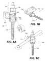
- FIG. 1Aillustrates a partial cutaway side view of a bone-anchoring device, according to an exemplary disclosed embodiment.
- FIG. 1Billustrates a perspective view of the bone-anchoring device of FIG. 1A .
- FIG. 1Cillustrates a perspective view of the bone-anchoring device of FIG. 1A with an implantable rod.
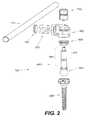
- FIG. 2illustrates an exploded view of the bone-anchoring device of FIG. 1C .
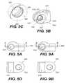
- FIG. 3Aprovides a side view of a screw of a bone-anchoring device, according to an exemplary disclosed embodiment.
- FIG. 3Bprovides a perspective view of the screw of FIG. 3A .
- FIG. 3Cprovides a side view of the screw of FIG. 3A , according to an exemplary disclosed embodiment.
- FIG. 4Aillustrates an exploded view of a rod connector of a bone-anchoring device, according to an exemplary disclosed embodiment.
- FIG. 4Billustrates a perspective view of the rod connector of FIG. 4A .
- FIG. 4Cshows an enlarged view of a portion of the rod connector of FIG. 4B .
- FIG. 5Aprovides a side view of another rod connector of a bone-anchoring device, according to an exemplary disclosed embodiment.
- FIG. 5Bprovides a perspective view of the rod connector of FIG. 5A .
- FIG. 5Cshows an enlarged view of a portion of the rod connector of FIG. 5B .
- FIG. 5Dshows a cross-sectional view of the rod connector of FIG. 5A along lines A-A.
- FIG. 6Aprovides a side view of a linking member of a bone-anchoring device, according to an exemplary disclosed embodiment.
- FIG. 6Bprovides a perspective view of the linking member of FIG. 6A .
- FIG. 6Cshows an enlarged view of a portion of the linking member of FIG. 6B .
- FIG. 7Aprovides a side view of a locking collar of a bone-anchoring device, according to an exemplary disclosed embodiment.
- FIG. 7Bprovides a perspective view of the locking collar of FIG. 7A .
- FIG. 8Aprovides a side view of a fastening member of a bone-anchoring device, according to an exemplary disclosed embodiment.
- FIG. 8Bprovides a perspective view of the fastening member of FIG. 8A .
- FIG. 9Aprovides a side view of yet another rod connector of a bone-anchoring device, according to an exemplary disclosed embodiment.
- FIG. 9Bprovides a cross-sectional view of the rod connector of FIG. 9A along lines B-B.
- FIGS. 1A-1Cillustrate a bone-anchoring device 100 , according to an exemplary disclosed embodiment.
- the bone-anchoring device 100includes a screw 200 , a rod connector 300 , and a linking member 400 .
- the screw 200may be configured to engage bony tissue to secure the rod connector 300 to bone.
- the screw 200will be configured to engage a vertebra or a sacrum to secure an implantable rod 110 (as shown in FIG. 1C ) to the vertebra or sacrum.
- FIG. 2illustrates the component parts of the bone-anchoring device 100 , according to one exemplary embodiment.
- the bone-anchoring device 100includes a screw 200 , a rod connector 300 , and a linking member 400 .
- the screw 200can be configured for insertion into bone tissue, while the linking member 400 can be configured to cooperate with the screw 200 in an angularly-adjustable relationship.
- the bone-anchoring device 100may further include a locking collar 600 configured to secure the linking member 400 to the screw 200 .
- the linking member 400may be sized and configured to cooperate with a rod connector 300 , as shown in FIGS. 1A-1C .
- a fastening member 700may be provided to engage an end portion 470 of the linking member to secure the linking member 400 to the rod connector 300 .
- FIGS. 3A-3Cillustrate the screw 200 , according to an exemplary disclosed embodiment.
- the screw 200can include a variety of suitable shapes, sizes, and/or materials.
- the screw 200can include a threaded shaft portion 220 and a head portion 240 .
- the head portion 240can further include a cup-shaped cavity 260 configured to engage the spherical head portion 420 of the linking member 400 (as shown in FIG. 1A ).
- the threaded shaft portion 220can include any suitable material or thread design.
- the threaded shaft portion 220will be produced from a material having biocompatibility with a tissue into which it is to be implanted.
- the threaded shaft portion 220will be produced from a material having a certain hardness, modulus of elasticity, or any other desired physical property.
- the thread size, shape, and numbermay be selected to securely fasten the screw 200 to bone.
- the distal end of the threaded shaft portion 220may include a groove 250 , which may provide a seat for a guide wire 252 , as shown in FIG. 3C .
- the guide wire 252may facilitate placement of the screw 200 in a selected bone 254 , such as a vertebral pedicle or other bone.
- the guide wire 252may be placed in a desired location through a small incision.
- the screw 200may be positioned adjacent the bone 254 by sliding the groove 250 of the screw 200 along the length of the guide wire 252 .
- the guide wire 252may also allow verification of the position of the screw using radiographic means (i.e., with x-ray or fluoroscopy).
- FIGS. 4A and 4Billustrate one embodiment for the rod connector 300 .
- the rod connector 300can include a connector body 320 having a through hole 340 for receiving the linking member 400 .
- the linking member through hole 340can include a polygon-shaped internal surface portion 390 (shown in detail in FIG. 4C ), which can form a complimentary connection with a polygon-shaped neck region 490 (as shown in FIGS. 6A and 6B ) of linking member 400 , thereby preventing rotation of the linking member 400 with respect to the rod connector 300 .
- the rod connector 300can further include a rod engaging section 360 .
- the rod engaging section 360can include a cylindrical bearing member 370 .
- the cylindrical bearing member 370can be disposed in a cavity 380 of the rod connector 300 (as shown in FIG. 4B ), which may be closed with a rod connector cap 385 .
- the cylindrical bearing member 370can include a rod through hole 372 for receiving a spinal rod.
- the cylindrical bearing member 370may include a liner.
- the linercan be formed from any suitable polymeric, ceramic or metallic material in order to reduce friction or provide desirable wear characteristics. Suitable polymeric materials can include, for example, a polyethylene, such as ultra high molecular weight polyethylene (UHMWPE), or polyetheretherketone (PEEK).
- UHMWPEultra high molecular weight polyethylene
- PEEKpolyetheretherketone
- the cylindrical bearing member 370may be configured to rotate about its longitudinal axis 374 . Rotation of the cylindrical bearing member 370 can provide a certain degree of rotational mobility to a rod 110 placed within the through hole 372 .
- the degree of mobilitymay be controlled by selecting the size of an opening 362 in rod engaging section 360 . The larger the opening 362 , the more clearance is provided for the rod 110 to be able to pivot with respect to the connector body 320 .
- a rod 110 placed through a cylindrical member 370 within the connector body 320may be configured to pivot up and down at an angle up to about 20.degree., up to about 30.degree., up to about 60.degree., up to about 90.degree., or up to about 120.degree.
- the cylindrical bearing member 370may be securely connected to the rod engaging section 360 or form a single unit with the rod engaging section 360 to provide no rotational movement about its axis 374 if desired.
- the rod 110may be configured to slide within the through hole 372 , thereby providing translational and/or rotational movement of the rod 110 with respect to the rod connector 300 .
- FIGS. 5A and 5Billustrate another type of rod connector 500 .
- This rod connector 500includes a C-shaped clamp with a rod receiving hole 510 and a linking member hole 520 .
- This type of rod connector 500may be selected when the rotational and/or translational movement of the cylindrical bearing member is not desired or needed.
- the linking member hole 520can include a polygon-shaped internal surface portion 530 which can form a complimentary connection with a polygon-shaped neck region 490 (as shown in FIGS. 6A and 6B ) of linking member 400 , thereby preventing rotation of the linking member 400 with respect to the rod connector 500 .
- the rod connectors 300 , 500 of FIGS. 4A-4C and 5 A- 5 Cmay also include a semi-spherical recess portion 397 , 597 .
- the rod connector 300may be configured such that, when assembled, the collar 600 and a portion of the screw head 240 may be positioned within the recess portion 397 of the rod connector 300 .
- the size of the recess portion 397 , 597may be selected based on the size of the screw head 240 and linking member head 420 and may be configured to control the degree of rotational mobility of the linking member 400 with respect to the screw 200 .
- the rod connectors 300 , 500may include a rim 395 , 595 adjacent to the semi-spherical recess portion 397 , 597 , as shown in FIGS. 4C and 5C .
- FIGS. 6A and 6Billustrate one embodiment of the linking member 400 .
- the linking member 400can include a spherical head portion 420 , a widened flange 440 including a rim surface 495 , and an elongate body 460 extending from the widened flange 440 .
- the elongate bodymay be passed through the opening 340 , 520 in the rod connector, and a fastening member 700 (as shown in FIGS. 8A and 8B ) may be secured to the elongate body 460 , thereby securing the rod connector 300 to the linking member 400 .
- the linking member 400may include a polygon-shaped neck region 490 configured to engage a complimentary surface of the linking member 300 , 500 so as to prevent rotation.
- the polygon-shaped neck region 490may include a number of flat panels 492 , which will form a desired surface configuration.
- the linking member 400is positioned against the screw 200 such that the spherical head portion 420 resides in the cup-shaped cavity 260 of the screw.
- the locking collar 600(as shown in FIGS. 7A and 7B ) can be placed over the linking member 400 and securely seated between the spherical head portion 420 of the linking member 400 and the cup-shaped cavity 260 of the screw 200 (as shown in FIG. 1A ). It is contemplated, of course, that a partially assembled device may be provided to a surgeon for convenience (i.e.
- the screw 200 and the linking member 400may be connected together by the locking collar 600 and provided to the surgeon as a unit, thereby eliminating the need for the previous assembly step), in order for the surgeon to be able to implant the screw 200 into a selected bone while the screw 200 is fastened to the linking member 400 .
- the rod connector 300can be placed over the linking member 400 by inserting the linking member end portion 470 through the rod connector linking member hole 340 .
- the entire device 100can be fully assembled by securing the fastening member 700 onto the linking member 400 and against the rod connector 300 .
- the linking member 400may include a threaded portion along the length of its elongate body 460 to enable attachment to the fastening member 700 .
- the linking member 400may include an elongate body 460 , which may include an end portion 470 .
- the elongate body end portionmay further include a narrowed or tapered tip 472 , which may be configured to be gripped or engaged by a surgeon's tool.
- the elongate body 460 of the linking member 400can include a thinner or scored section 480 .
- the end portion 470may extend a certain distance from the rod connector 300 during implantation, thereby facilitating manipulation of the linking member 400 and or connectors 300 , 500 by a surgeon.
- the thinner or scored section 480may allow a surgeon to break off the end portion 470 of the elongate body 460 that is distal to the thinner or scored section 480 . This will prevent excess protruding material after implantation, thereby reducing the foreign material left in a patient and preventing the end portion 470 from causing mechanical damage to surrounding tissue.
- the linking member 400may be produced from a number of different materials.
- the specific materialmay be selected based on desired physical properties, biocompatibility, cost, and/or any other suitable factor.
- suitable materialsmay include various polymeric materials, ceramics, and/or metals. Such materials may include polyethylene, ultra high molecular weight polyethylene, PEEK, cobalt-chrome, and/or titanium or its alloys.
- the linking member 400may be produced from multiple materials.
- the spherical head 420may be produced from a hard, wear-resistant material
- the elongate body 460may be produced from a softer material.
- the end portion 470may be produced from a material that can be relatively easily broken or cut at the thinner or scored section 480 .
- the linking member spherical head 420will be produced from a polymeric material such as polyethylene or ultra-high molecular weight polyethylene.
- the linking member spherical head 420may be coated to reduce wear.
- suitable surface coatingsmay include a variety of ceramic, composite, and/or polymeric materials.
- FIGS. 7A and 7Billustrate a more detailed view of the locking collar 600 , according to an exemplary disclosed embodiment.
- the locking collar 600may include a number of suitable fixation methods.
- the locking collar 600can be configured to form a friction fit connection, a snap-fit connection, a threaded connection, or any other suitable connection.
- the locking collar 600may be removably or permanently fixed to the linking member 400 and the screw 200 .
- the head 240 of the screw 200may include a side hole 280 .
- a fixation toolmay be inserted through the side hole 280 to secure the locking collar 600 in place.
- a small rodmay be inserted through the side hole 280 with enough force to produce a small deformation in an inner surface 285 of the screw cavity and/or on a surface 610 of the locking collar. This deformation may prevent the locking collar 600 from being unscrewed (in the case of a threaded collar, the deformation would occur on the threads) or from sliding out (in the case of a friction fit collar).
- a pin or boltmay be inserted through the side hole 280 and left in place after assembly of the bone-anchoring device 100 , thereby securing the locking collar 600 in place.
- the linking member 400can include a widened flange 440 terminating at a rim surface 495 adjacent the neck region 490 .
- the rim surface 495engages the rim 395 , 595 of the rod connector 300 , 500 .
- the abutment of the rim 395 , 595 of the rod connector 300 , 500 against the rim surface 495 of the linking member 400serves to limit axial positioning of the two components relative to one another. In other words, the engagement of the rim 395 , 595 of the rod connector 300 , 500 with the rim surface of the linking member 400 , as shown in FIG.
- FIGS. 8A and 8Billustrate the fastening member 700 , according to an exemplary disclosed embodiment.
- the fastening member 700can include a variety of suitable fastening member types.
- the elongate body 460will include a threaded region over at least a portion of its length, and the fastening member 700 will include a nut that can be screwed onto the elongate body until it forms a tight connection with the rod connector 300 , 500 .
- the fastening member 700may be a press fit connector, friction fit connector, or any other suitable connector type.
- the rod connector 300 , 500may be configured with a recess cavity for receiving a portion of the fastening member 700 .
- the fastening member 700will include a narrowed section 710 connecting a lower half 720 and upper half 730 .
- the narrowed section 710may be configured to break when a certain torque is applied to the fastening member 700 .
- a surgeonwill tighten the fastening member 700 onto the linking member 400 .
- the narrowed section 710may break, thereby preventing excessive torque from being exerted on the device.
- the upper half 730may include a widened internal diameter, which will allow the upper half 730 to be easily removed once the narrowed section 710 has been broken or cut.
- the bone-anchoring device 100 of the present disclosuremay be used to secure a variety of implantable rods to bone.
- the bone-anchoring device 100may be used with a spinal treatment system.
- Suitable spinal treatment systemsinclude mobile dynamic treatment systems for treatment of scoliosis and other spinal disorders. Examples of such mobile dynamic treatment systems are disclosed in U.S. Pat. No. 5,413,576 issued to Rivard on May 9, 1995 and U.S. Pat. No. 6,554,831 issued to Rivard on Apr. 29, 2003, both of which are herein incorporated by reference in their entirety.
- the bone-anchoring device 100may be used with any suitable implantable rod.
- FIG. 5Dillustrates a cross-sectional view of the rod connector 500 of FIG. 5A along lines A-A, showing a cylindrical rod receiving hole 510 configured for receiving a straight implantable rod 110 .
- the rod connector 500 ′may include a shaped rod receiving hole 510 ′.
- the rod connector 500 ′may be similar in most respects to the rod connector 500 of FIGS. 5A-5D and can include a linking member hole 520 ′, but can contain a curved rod receiving hole 510 ′ in which the openings of the hole 510 ′ extend in a slight flare.
- Such a configurationwould enable a curved implantable rod to pass through the rod connector 500 ′.
- the cylindrical bearing member 370 of rod connector 300with a similarly curved rod-receiving through hole in order to accommodate a curved rod, if desired,
- the rod connector 300may include a cylindrical bearing member 370 configured to rotate along its axis 374 , thereby providing a certain degree of rotation to a rod 110 disposed in the cylindrical body through hole 372 .
- other types of sliding and rotational mobilitymay be provided.
- the rod 110may be configured to be rotatably or slidably mobile with respect to the rod connector 300 , 500 once inserted through a rod through hole 372 , 510 .
- Rotational movement of the rod 110 with respect to the rod connector 300 , 500will provide a certain degree of controlled mobility when implanted in a patient.
- sliding mobility of the rod connector 300 , 500can allow some degree of flexion and/or extension, while also allowing continued elongation of the spine. As noted by Rivard, this may be important when the bone-anchoring device 100 is implanted in a juvenile patient who will continue to grow.
- rod connectors 300 , 500may be configured to prevent movement in one or more degrees of freedom.
- rod connector 500may be configured to prevent translational or sliding movement of a rod 110 .
- Such rod connectors 500which may limit translational or sliding movement, may be included as part of a dynamic treatment system, which may include combinations of sliding and fixed connectors 300 , 500 .
- the linking member spherical head 420may rotate with respect to the axis of the screw 200 after assembly.
- This gap 800can allow some freedom of movement, or rotation, of the spherical head 420 of the linking member 400 within the cup-shaped cavity 260 of the screw 200 .
- the rotational movement of the linking member spherical head 420 with respect to the screw 200will provide a number of advantages.
- the screw 200can be implanted at a variety of suitable angles in a patient's bone while still allowing appropriate engagement of the linking member 400 with the screw cup-shaped cavity 260 .
- continued rotational mobility of the linking member 400 with respect to the screw 200will provide controlled dynamic movement, which may be desired for some implantable devices.
- continued mobility of the implant componentsmay not be desired.
- the size and shape of the screw head 240 , linking member spherical head 420 , and rod connector 300 , 500may be selected to prevent movement after implantation.
- a rod connector 500may be selected that does not include a cylindrical bearing member 370 , thereby preventing another type of rotational movement of the rod 110 with respect to the rod connector 500 .
Landscapes
- Health & Medical Sciences (AREA)
- Orthopedic Medicine & Surgery (AREA)
- Life Sciences & Earth Sciences (AREA)
- Surgery (AREA)
- Neurology (AREA)
- Heart & Thoracic Surgery (AREA)
- Engineering & Computer Science (AREA)
- Biomedical Technology (AREA)
- Nuclear Medicine, Radiotherapy & Molecular Imaging (AREA)
- Medical Informatics (AREA)
- Molecular Biology (AREA)
- Animal Behavior & Ethology (AREA)
- General Health & Medical Sciences (AREA)
- Public Health (AREA)
- Veterinary Medicine (AREA)
- Surgical Instruments (AREA)
- Prostheses (AREA)
Abstract
Description
Claims (16)
Priority Applications (1)
| Application Number | Priority Date | Filing Date | Title |
|---|---|---|---|
| US13/088,741US8470001B2 (en) | 2005-10-06 | 2011-04-18 | Polyaxial screw |
Applications Claiming Priority (3)
| Application Number | Priority Date | Filing Date | Title |
|---|---|---|---|
| US72404605P | 2005-10-06 | 2005-10-06 | |
| US11/538,524US7927359B2 (en) | 2005-10-06 | 2006-10-04 | Polyaxial screw |
| US13/088,741US8470001B2 (en) | 2005-10-06 | 2011-04-18 | Polyaxial screw |
Related Parent Applications (1)
| Application Number | Title | Priority Date | Filing Date |
|---|---|---|---|
| US11/538,524ContinuationUS7927359B2 (en) | 2005-10-06 | 2006-10-04 | Polyaxial screw |
Publications (2)
| Publication Number | Publication Date |
|---|---|
| US20110196427A1 US20110196427A1 (en) | 2011-08-11 |
| US8470001B2true US8470001B2 (en) | 2013-06-25 |
Family
ID=37663374
Family Applications (2)
| Application Number | Title | Priority Date | Filing Date |
|---|---|---|---|
| US11/538,524Active2028-01-21US7927359B2 (en) | 2005-10-06 | 2006-10-04 | Polyaxial screw |
| US13/088,741Expired - Fee RelatedUS8470001B2 (en) | 2005-10-06 | 2011-04-18 | Polyaxial screw |
Family Applications Before (1)
| Application Number | Title | Priority Date | Filing Date |
|---|---|---|---|
| US11/538,524Active2028-01-21US7927359B2 (en) | 2005-10-06 | 2006-10-04 | Polyaxial screw |
Country Status (13)
| Country | Link |
|---|---|
| US (2) | US7927359B2 (en) |
| EP (1) | EP1931268B1 (en) |
| JP (1) | JP2009512466A (en) |
| KR (1) | KR20080069595A (en) |
| CN (1) | CN101321501B (en) |
| AR (1) | AR058687A1 (en) |
| AU (1) | AU2006299388A1 (en) |
| CA (1) | CA2624861A1 (en) |
| ES (1) | ES2451529T3 (en) |
| IL (1) | IL190622A0 (en) |
| TW (1) | TWI446888B (en) |
| WO (1) | WO2007041686A1 (en) |
| ZA (1) | ZA200802954B (en) |
Cited By (22)
| Publication number | Priority date | Publication date | Assignee | Title |
|---|---|---|---|---|
| US20120209332A1 (en)* | 2011-02-14 | 2012-08-16 | Pioneer Surgical Technology, Inc. | Spinal Fixation System And Method |
| US20140074169A1 (en)* | 2012-09-13 | 2014-03-13 | Warsaw Orthopedic, Inc. | Spinal correction system and method |
| US8828058B2 (en) | 2008-11-11 | 2014-09-09 | Kspine, Inc. | Growth directed vertebral fixation system with distractible connector(s) and apical control |
| US8920472B2 (en) | 2011-11-16 | 2014-12-30 | Kspine, Inc. | Spinal correction and secondary stabilization |
| US9011491B2 (en) | 2004-08-03 | 2015-04-21 | K Spine, Inc. | Facet device and method |
| US9168071B2 (en) | 2009-09-15 | 2015-10-27 | K2M, Inc. | Growth modulation system |
| US9173681B2 (en) | 2009-03-26 | 2015-11-03 | K2M, Inc. | Alignment system with longitudinal support features |
| US9333009B2 (en) | 2011-06-03 | 2016-05-10 | K2M, Inc. | Spinal correction system actuators |
| US9468471B2 (en) | 2013-09-17 | 2016-10-18 | K2M, Inc. | Transverse coupler adjuster spinal correction systems and methods |
| US9468468B2 (en) | 2011-11-16 | 2016-10-18 | K2M, Inc. | Transverse connector for spinal stabilization system |
| US9468469B2 (en) | 2011-11-16 | 2016-10-18 | K2M, Inc. | Transverse coupler adjuster spinal correction systems and methods |
| US10149702B2 (en) | 2015-01-12 | 2018-12-11 | Imds Llc | Polyaxial screw and rod system |
| US10238432B2 (en) | 2017-02-10 | 2019-03-26 | Medos International Sàrl | Tandem rod connectors and related methods |
| US10321939B2 (en) | 2016-05-18 | 2019-06-18 | Medos International Sarl | Implant connectors and related methods |
| US10342581B2 (en) | 2011-11-16 | 2019-07-09 | K2M, Inc. | System and method for spinal correction |
| US10398476B2 (en) | 2016-12-13 | 2019-09-03 | Medos International Sàrl | Implant adapters and related methods |
| US10492835B2 (en) | 2016-12-19 | 2019-12-03 | Medos International Sàrl | Offset rods, offset rod connectors, and related methods |
| US10517647B2 (en) | 2016-05-18 | 2019-12-31 | Medos International Sarl | Implant connectors and related methods |
| US10561454B2 (en) | 2017-03-28 | 2020-02-18 | Medos International Sarl | Articulating implant connectors and related methods |
| US10702311B2 (en) | 2011-11-16 | 2020-07-07 | K2M, Inc. | Spinal correction and secondary stabilization |
| US10966761B2 (en) | 2017-03-28 | 2021-04-06 | Medos International Sarl | Articulating implant connectors and related methods |
| US11076890B2 (en) | 2017-12-01 | 2021-08-03 | Medos International Sàrl | Rod-to-rod connectors having robust rod closure mechanisms and related methods |
Families Citing this family (119)
| Publication number | Priority date | Publication date | Assignee | Title |
|---|---|---|---|---|
| US7833250B2 (en) | 2004-11-10 | 2010-11-16 | Jackson Roger P | Polyaxial bone screw with helically wound capture connection |
| US8353932B2 (en) | 2005-09-30 | 2013-01-15 | Jackson Roger P | Polyaxial bone anchor assembly with one-piece closure, pressure insert and plastic elongate member |
| US7862587B2 (en) | 2004-02-27 | 2011-01-04 | Jackson Roger P | Dynamic stabilization assemblies, tool set and method |
| US10258382B2 (en) | 2007-01-18 | 2019-04-16 | Roger P. Jackson | Rod-cord dynamic connection assemblies with slidable bone anchor attachment members along the cord |
| US10729469B2 (en) | 2006-01-09 | 2020-08-04 | Roger P. Jackson | Flexible spinal stabilization assembly with spacer having off-axis core member |
| US8292926B2 (en) | 2005-09-30 | 2012-10-23 | Jackson Roger P | Dynamic stabilization connecting member with elastic core and outer sleeve |
| FR2835735B1 (en)* | 2002-02-11 | 2004-11-12 | Fixano | VERTEBRAL ARTHRODESIS MATERIAL |
| US8876868B2 (en) | 2002-09-06 | 2014-11-04 | Roger P. Jackson | Helical guide and advancement flange with radially loaded lip |
| WO2006052796A2 (en) | 2004-11-10 | 2006-05-18 | Jackson Roger P | Helical guide and advancement flange with break-off extensions |
| US8172885B2 (en)* | 2003-02-05 | 2012-05-08 | Pioneer Surgical Technology, Inc. | Bone plate system |
| US6716214B1 (en) | 2003-06-18 | 2004-04-06 | Roger P. Jackson | Polyaxial bone screw with spline capture connection |
| US7621918B2 (en) | 2004-11-23 | 2009-11-24 | Jackson Roger P | Spinal fixation tool set and method |
| US7377923B2 (en) | 2003-05-22 | 2008-05-27 | Alphatec Spine, Inc. | Variable angle spinal screw assembly |
| US8377102B2 (en) | 2003-06-18 | 2013-02-19 | Roger P. Jackson | Polyaxial bone anchor with spline capture connection and lower pressure insert |
| US8398682B2 (en) | 2003-06-18 | 2013-03-19 | Roger P. Jackson | Polyaxial bone screw assembly |
| US7766915B2 (en) | 2004-02-27 | 2010-08-03 | Jackson Roger P | Dynamic fixation assemblies with inner core and outer coil-like member |
| US8257398B2 (en) | 2003-06-18 | 2012-09-04 | Jackson Roger P | Polyaxial bone screw with cam capture |
| US8926670B2 (en) | 2003-06-18 | 2015-01-06 | Roger P. Jackson | Polyaxial bone screw assembly |
| US8137386B2 (en) | 2003-08-28 | 2012-03-20 | Jackson Roger P | Polyaxial bone screw apparatus |
| US7776067B2 (en) | 2005-05-27 | 2010-08-17 | Jackson Roger P | Polyaxial bone screw with shank articulation pressure insert and method |
| US7967850B2 (en) | 2003-06-18 | 2011-06-28 | Jackson Roger P | Polyaxial bone anchor with helical capture connection, insert and dual locking assembly |
| US8105367B2 (en) | 2003-09-29 | 2012-01-31 | Smith & Nephew, Inc. | Bone plate and bone plate assemblies including polyaxial fasteners |
| US7179261B2 (en) | 2003-12-16 | 2007-02-20 | Depuy Spine, Inc. | Percutaneous access devices and bone anchor assemblies |
| US7527638B2 (en) | 2003-12-16 | 2009-05-05 | Depuy Spine, Inc. | Methods and devices for minimally invasive spinal fixation element placement |
| US11419642B2 (en) | 2003-12-16 | 2022-08-23 | Medos International Sarl | Percutaneous access devices and bone anchor assemblies |
| US8152810B2 (en) | 2004-11-23 | 2012-04-10 | Jackson Roger P | Spinal fixation tool set and method |
| US7160300B2 (en) | 2004-02-27 | 2007-01-09 | Jackson Roger P | Orthopedic implant rod reduction tool set and method |
| JP2007525274A (en) | 2004-02-27 | 2007-09-06 | ロジャー・ピー・ジャクソン | Orthopedic implant rod reduction instrument set and method |
| US11241261B2 (en) | 2005-09-30 | 2022-02-08 | Roger P Jackson | Apparatus and method for soft spinal stabilization using a tensionable cord and releasable end structure |
| US7651502B2 (en) | 2004-09-24 | 2010-01-26 | Jackson Roger P | Spinal fixation tool set and method for rod reduction and fastener insertion |
| US8926672B2 (en) | 2004-11-10 | 2015-01-06 | Roger P. Jackson | Splay control closure for open bone anchor |
| US9980753B2 (en) | 2009-06-15 | 2018-05-29 | Roger P Jackson | pivotal anchor with snap-in-place insert having rotation blocking extensions |
| US8444681B2 (en) | 2009-06-15 | 2013-05-21 | Roger P. Jackson | Polyaxial bone anchor with pop-on shank, friction fit retainer and winged insert |
| US9168069B2 (en) | 2009-06-15 | 2015-10-27 | Roger P. Jackson | Polyaxial bone anchor with pop-on shank and winged insert with lower skirt for engaging a friction fit retainer |
| US8308782B2 (en) | 2004-11-23 | 2012-11-13 | Jackson Roger P | Bone anchors with longitudinal connecting member engaging inserts and closures for fixation and optional angulation |
| WO2006057837A1 (en) | 2004-11-23 | 2006-06-01 | Jackson Roger P | Spinal fixation tool attachment structure |
| US7875065B2 (en) | 2004-11-23 | 2011-01-25 | Jackson Roger P | Polyaxial bone screw with multi-part shank retainer and pressure insert |
| US9216041B2 (en) | 2009-06-15 | 2015-12-22 | Roger P. Jackson | Spinal connecting members with tensioned cords and rigid sleeves for engaging compression inserts |
| US7901437B2 (en) | 2007-01-26 | 2011-03-08 | Jackson Roger P | Dynamic stabilization member with molded connection |
| US10076361B2 (en) | 2005-02-22 | 2018-09-18 | Roger P. Jackson | Polyaxial bone screw with spherical capture, compression and alignment and retention structures |
| US8382807B2 (en) | 2005-07-25 | 2013-02-26 | Smith & Nephew, Inc. | Systems and methods for using polyaxial plates |
| CA2616798C (en) | 2005-07-25 | 2014-01-28 | Smith & Nephew, Inc. | Systems and methods for using polyaxial plates |
| US8105368B2 (en) | 2005-09-30 | 2012-01-31 | Jackson Roger P | Dynamic stabilization connecting member with slitted core and outer sleeve |
| US7927359B2 (en) | 2005-10-06 | 2011-04-19 | Paradigm Spine, Llc | Polyaxial screw |
| CA2670988C (en) | 2006-12-08 | 2014-03-25 | Roger P. Jackson | Tool system for dynamic spinal implants |
| US8366745B2 (en) | 2007-05-01 | 2013-02-05 | Jackson Roger P | Dynamic stabilization assembly having pre-compressed spacers with differential displacements |
| US8475498B2 (en) | 2007-01-18 | 2013-07-02 | Roger P. Jackson | Dynamic stabilization connecting member with cord connection |
| US10792074B2 (en) | 2007-01-22 | 2020-10-06 | Roger P. Jackson | Pivotal bone anchor assemly with twist-in-place friction fit insert |
| US8979904B2 (en) | 2007-05-01 | 2015-03-17 | Roger P Jackson | Connecting member with tensioned cord, low profile rigid sleeve and spacer with torsion control |
| US10383660B2 (en) | 2007-05-01 | 2019-08-20 | Roger P. Jackson | Soft stabilization assemblies with pretensioned cords |
| US8048123B2 (en) | 2007-06-05 | 2011-11-01 | Spartek Medical, Inc. | Spine implant with a deflection rod system and connecting linkages and method |
| US8083772B2 (en)* | 2007-06-05 | 2011-12-27 | Spartek Medical, Inc. | Dynamic spinal rod assembly and method for dynamic stabilization of the spine |
| US8114134B2 (en) | 2007-06-05 | 2012-02-14 | Spartek Medical, Inc. | Spinal prosthesis having a three bar linkage for motion preservation and dynamic stabilization of the spine |
| US8048115B2 (en)* | 2007-06-05 | 2011-11-01 | Spartek Medical, Inc. | Surgical tool and method for implantation of a dynamic bone anchor |
| US8092501B2 (en)* | 2007-06-05 | 2012-01-10 | Spartek Medical, Inc. | Dynamic spinal rod and method for dynamic stabilization of the spine |
| US8048128B2 (en) | 2007-06-05 | 2011-11-01 | Spartek Medical, Inc. | Revision system and method for a dynamic stabilization and motion preservation spinal implantation system and method |
| US8021396B2 (en)* | 2007-06-05 | 2011-09-20 | Spartek Medical, Inc. | Configurable dynamic spinal rod and method for dynamic stabilization of the spine |
| US8623019B2 (en) | 2007-07-03 | 2014-01-07 | Pioneer Surgical Technology, Inc. | Bone plate system |
| US8361126B2 (en)* | 2007-07-03 | 2013-01-29 | Pioneer Surgical Technology, Inc. | Bone plate system |
| EP2047810B1 (en)* | 2007-10-11 | 2011-09-28 | BIEDERMANN MOTECH GmbH | Modular rod system for spinal stabilization |
| US20090182384A1 (en)* | 2008-01-14 | 2009-07-16 | Warsaw Orthopedic, Inc. | Material combinations for medical device implants |
| US8333792B2 (en)* | 2008-02-26 | 2012-12-18 | Spartek Medical, Inc. | Load-sharing bone anchor having a deflectable post and method for dynamic stabilization of the spine |
| US8267979B2 (en) | 2008-02-26 | 2012-09-18 | Spartek Medical, Inc. | Load-sharing bone anchor having a deflectable post and axial spring and method for dynamic stabilization of the spine |
| US8097024B2 (en)* | 2008-02-26 | 2012-01-17 | Spartek Medical, Inc. | Load-sharing bone anchor having a deflectable post and method for stabilization of the spine |
| US8211155B2 (en) | 2008-02-26 | 2012-07-03 | Spartek Medical, Inc. | Load-sharing bone anchor having a durable compliant member and method for dynamic stabilization of the spine |
| US8083775B2 (en)* | 2008-02-26 | 2011-12-27 | Spartek Medical, Inc. | Load-sharing bone anchor having a natural center of rotation and method for dynamic stabilization of the spine |
| US8337536B2 (en)* | 2008-02-26 | 2012-12-25 | Spartek Medical, Inc. | Load-sharing bone anchor having a deflectable post with a compliant ring and method for stabilization of the spine |
| US8007518B2 (en)* | 2008-02-26 | 2011-08-30 | Spartek Medical, Inc. | Load-sharing component having a deflectable post and method for dynamic stabilization of the spine |
| US8057517B2 (en) | 2008-02-26 | 2011-11-15 | Spartek Medical, Inc. | Load-sharing component having a deflectable post and centering spring and method for dynamic stabilization of the spine |
| US8048125B2 (en)* | 2008-02-26 | 2011-11-01 | Spartek Medical, Inc. | Versatile offset polyaxial connector and method for dynamic stabilization of the spine |
| AU2010260521C1 (en) | 2008-08-01 | 2013-08-01 | Roger P. Jackson | Longitudinal connecting member with sleeved tensioned cords |
| US8147523B2 (en)* | 2008-09-09 | 2012-04-03 | Warsaw Orthopedic, Inc. | Offset vertebral rod connector |
| CN102215767A (en)* | 2008-09-26 | 2011-10-12 | 斯帕泰科医疗有限公司 | Load-sharing bone anchor, dynamic vertical rod and assemblies for dynamic stabilization of the spine |
| EP2328496A4 (en)* | 2008-09-26 | 2013-07-03 | Spartek Medical Inc | Load-sharing bone anchor, dynamic vertical rod and assemblies for dynamic stabilization of the spine |
| US20100160978A1 (en)* | 2008-12-23 | 2010-06-24 | John Carbone | Bone screw assembly with non-uniform material |
| US20110040331A1 (en)* | 2009-05-20 | 2011-02-17 | Jose Fernandez | Posterior stabilizer |
| US11229457B2 (en) | 2009-06-15 | 2022-01-25 | Roger P. Jackson | Pivotal bone anchor assembly with insert tool deployment |
| US9668771B2 (en) | 2009-06-15 | 2017-06-06 | Roger P Jackson | Soft stabilization assemblies with off-set connector |
| CN103826560A (en) | 2009-06-15 | 2014-05-28 | 罗杰.P.杰克逊 | Polyaxial Bone Anchor with Socket Stem and Winged Inserts with Friction Fit Compression Collars |
| US8998959B2 (en) | 2009-06-15 | 2015-04-07 | Roger P Jackson | Polyaxial bone anchors with pop-on shank, fully constrained friction fit retainer and lock and release insert |
| EP2279706B1 (en)* | 2009-07-28 | 2011-09-28 | Biedermann Motech GmbH | Bone anchoring device |
| EP2485654B1 (en) | 2009-10-05 | 2021-05-05 | Jackson P. Roger | Polyaxial bone anchor with non-pivotable retainer and pop-on shank, some with friction fit |
| US8211151B2 (en)* | 2009-10-30 | 2012-07-03 | Warsaw Orthopedic | Devices and methods for dynamic spinal stabilization and correction of spinal deformities |
| US9078701B2 (en)* | 2009-11-09 | 2015-07-14 | Centinel Spine, Inc. | System and method for stabilizing a posterior fusion over motion segments |
| TWI399192B (en)* | 2009-11-18 | 2013-06-21 | Accumis Inc | Universal direction medical positioning structure |
| CN102695465A (en) | 2009-12-02 | 2012-09-26 | 斯帕泰克医疗股份有限公司 | Low profile spinal prosthesis incorporating a bone anchor having a deflectable post and a compound spinal rod |
| US8617216B2 (en)* | 2010-04-05 | 2013-12-31 | David L. Brumfield | Fully-adjustable bone fixation device |
| US12383311B2 (en) | 2010-05-14 | 2025-08-12 | Roger P. Jackson | Pivotal bone anchor assembly and method for use thereof |
| US20110307015A1 (en) | 2010-06-10 | 2011-12-15 | Spartek Medical, Inc. | Adaptive spinal rod and methods for stabilization of the spine |
| AU2011299558A1 (en) | 2010-09-08 | 2013-05-02 | Roger P. Jackson | Dynamic stabilization members with elastic and inelastic sections |
| AU2011324058A1 (en) | 2010-11-02 | 2013-06-20 | Roger P. Jackson | Polyaxial bone anchor with pop-on shank and pivotable retainer |
| US8337530B2 (en)* | 2011-03-09 | 2012-12-25 | Zimmer Spine, Inc. | Polyaxial pedicle screw with increased angulation |
| JP5865479B2 (en) | 2011-03-24 | 2016-02-17 | ロジャー・ピー・ジャクソン | Multiaxial bone anchor with compound joint and pop-mounted shank |
| AU2012271441B2 (en) | 2011-06-15 | 2017-02-02 | Smith & Nephew, Inc. | Variable angle locking implant |
| FR2978343B1 (en)* | 2011-07-25 | 2013-08-23 | Medicrea International | ANCHORING BODY FOR VERTEBRAL OSTEOSYNTHESIS EQUIPMENT |
| RU2601986C2 (en)* | 2011-12-14 | 2016-11-10 | Инновейтив Сёрджикал Дизайнс, Инк. | Minimally invasive method and apparatus for stabilizing the spinal column |
| US8911479B2 (en) | 2012-01-10 | 2014-12-16 | Roger P. Jackson | Multi-start closures for open implants |
| US8430916B1 (en) | 2012-02-07 | 2013-04-30 | Spartek Medical, Inc. | Spinal rod connectors, methods of use, and spinal prosthesis incorporating spinal rod connectors |
| US20130218207A1 (en)* | 2012-02-16 | 2013-08-22 | Warsaw Orthopedic, Inc | Dynamic multi-axial anchor |
| US9247974B2 (en)* | 2012-07-06 | 2016-02-02 | Clariance | Polyaxial screw with mechanical thread and its friction device |
| FR2992847B1 (en)* | 2012-07-06 | 2015-06-05 | Clariance | POLY AXIAL SCREW WITH MECHANICAL THREADING AND FRICTION DEVICE |
| US8911478B2 (en) | 2012-11-21 | 2014-12-16 | Roger P. Jackson | Splay control closure for open bone anchor |
| US10058354B2 (en) | 2013-01-28 | 2018-08-28 | Roger P. Jackson | Pivotal bone anchor assembly with frictional shank head seating surfaces |
| US8852239B2 (en) | 2013-02-15 | 2014-10-07 | Roger P Jackson | Sagittal angle screw with integral shank and receiver |
| US9510872B2 (en) | 2013-03-15 | 2016-12-06 | Jcbd, Llc | Spinal stabilization system |
| US10154861B2 (en) | 2013-03-15 | 2018-12-18 | Jcbd, Llc | Spinal stabilization system |
| US9987047B2 (en)* | 2013-10-07 | 2018-06-05 | Spine Wave, Inc. | Translating polyaxial screw |
| US9566092B2 (en) | 2013-10-29 | 2017-02-14 | Roger P. Jackson | Cervical bone anchor with collet retainer and outer locking sleeve |
| US9717533B2 (en) | 2013-12-12 | 2017-08-01 | Roger P. Jackson | Bone anchor closure pivot-splay control flange form guide and advancement structure |
| US9451993B2 (en) | 2014-01-09 | 2016-09-27 | Roger P. Jackson | Bi-radial pop-on cervical bone anchor |
| US10064658B2 (en) | 2014-06-04 | 2018-09-04 | Roger P. Jackson | Polyaxial bone anchor with insert guides |
| US9597119B2 (en) | 2014-06-04 | 2017-03-21 | Roger P. Jackson | Polyaxial bone anchor with polymer sleeve |
| FR3035318B1 (en)* | 2015-04-24 | 2017-05-19 | Medicrea Int | MATERIAL OF VERTEBRAL OSTEOSYNTHESIS |
| GB2557840B (en) | 2015-09-18 | 2021-07-21 | Smith & Nephew Inc | Bone plate |
| CN105250017B (en)* | 2015-11-30 | 2018-03-06 | 昆明医科大学第二附属医院 | A kind of orthopedic rod connector that multidirectional offer angle compensation is provided |
| CN106473836A (en)* | 2016-12-12 | 2017-03-08 | 运怡(北京)医疗器械有限公司 | Porous PEEK interface nail |
| US11707299B2 (en)* | 2018-07-19 | 2023-07-25 | Warsaw Orthopedic, Inc. | Antenna placement for a digital set screw |
| US20200281736A1 (en)* | 2019-03-04 | 2020-09-10 | K2M, Inc. | Intervertebral Implant Assembly and Instruments Therefor |
| US11877779B2 (en) | 2020-03-26 | 2024-01-23 | Xtant Medical Holdings, Inc. | Bone plate system |
Citations (113)
| Publication number | Priority date | Publication date | Assignee | Title |
|---|---|---|---|---|
| US4887596A (en) | 1988-03-02 | 1989-12-19 | Synthes (U.S.A.) | Open backed pedicle screw |
| US4946458A (en) | 1986-04-25 | 1990-08-07 | Harms Juergen | Pedicle screw |
| US5176678A (en) | 1991-03-14 | 1993-01-05 | Tsou Paul M | Orthopaedic device with angularly adjustable anchor attachments to the vertebrae |
| US5207678A (en) | 1989-07-20 | 1993-05-04 | Prufer | Pedicle screw and receiver member therefore |
| US5261910A (en) | 1992-02-19 | 1993-11-16 | Acromed Corporation | Apparatus for maintaining spinal elements in a desired spatial relationship |
| US5261909A (en) | 1992-02-18 | 1993-11-16 | Danek Medical, Inc. | Variable angle screw for spinal implant system |
| US5304179A (en) | 1993-06-17 | 1994-04-19 | Amei Technologies Inc. | System and method for installing a spinal fixation system at variable angles |
| US5395371A (en) | 1991-07-15 | 1995-03-07 | Danek Group, Inc. | Spinal fixation system |
| US5413576A (en) | 1993-02-10 | 1995-05-09 | Rivard; Charles-Hilaire | Apparatus for treating spinal disorder |
| US5466237A (en) | 1993-11-19 | 1995-11-14 | Cross Medical Products, Inc. | Variable locking stabilizer anchor seat and screw |
| US5486174A (en) | 1993-02-24 | 1996-01-23 | Soprane S.A. | Fastener for the osteosynthesis of the spinal column |
| US5499983A (en) | 1994-02-23 | 1996-03-19 | Smith & Nephew Richards, Inc. | Variable angle spinal screw |
| US5501684A (en) | 1992-06-25 | 1996-03-26 | Synthes (U.S.A.) | Osteosynthetic fixation device |
| US5545165A (en) | 1992-10-09 | 1996-08-13 | Biedermann Motech Gmbh | Anchoring member |
| FR2730405A1 (en) | 1995-02-10 | 1996-08-14 | Moreau Patrice | Spinal column prosthesis |
| US5549608A (en) | 1995-07-13 | 1996-08-27 | Fastenetix, L.L.C. | Advanced polyaxial locking screw and coupling element device for use with rod fixation apparatus |
| US5554157A (en) | 1995-07-13 | 1996-09-10 | Fastenetix, L.L.C. | Rod securing polyaxial locking screw and coupling element assembly |
| US5569247A (en) | 1995-03-27 | 1996-10-29 | Smith & Nephew Richards, Inc. | Enhanced variable angle bone bolt |
| US5578034A (en) | 1995-06-07 | 1996-11-26 | Danek Medical, Inc. | Apparatus for preventing screw backout in a bone plate fixation system |
| US5584834A (en) | 1995-07-13 | 1996-12-17 | Fastenetix, L.L.C. | Polyaxial locking screw and coupling element assembly for use with side loading rod fixation apparatus |
| US5586984A (en) | 1995-07-13 | 1996-12-24 | Fastenetix, L.L.C. | Polyaxial locking screw and coupling element assembly for use with rod fixation apparatus |
| US5591166A (en) | 1995-03-27 | 1997-01-07 | Smith & Nephew Richards, Inc. | Multi angle bone bolt |
| US5628740A (en) | 1993-12-23 | 1997-05-13 | Mullane; Thomas S. | Articulating toggle bolt bone screw |
| US5647873A (en) | 1995-04-13 | 1997-07-15 | Fastenetix, L.L.C. | Bicentric polyaxial locking screw and coupling element |
| US5669911A (en) | 1995-04-13 | 1997-09-23 | Fastenetix, L.L.C. | Polyaxial pedicle screw |
| US5672176A (en) | 1995-03-15 | 1997-09-30 | Biedermann; Lutz | Anchoring member |
| US5716356A (en) | 1994-07-18 | 1998-02-10 | Biedermann; Lutz | Anchoring member and adjustment tool therefor |
| US5725528A (en) | 1997-02-12 | 1998-03-10 | Third Millennium Engineering, Llc | Modular polyaxial locking pedicle screw |
| US5728098A (en) | 1996-11-07 | 1998-03-17 | Sdgi Holdings, Inc. | Multi-angle bone screw assembly using shape-memory technology |
| US5733286A (en) | 1997-02-12 | 1998-03-31 | Third Millennium Engineering, Llc | Rod securing polyaxial locking screw and coupling element assembly |
| US5733285A (en) | 1995-07-13 | 1998-03-31 | Fastenetix, Llc | Polyaxial locking mechanism |
| US5735851A (en) | 1996-10-09 | 1998-04-07 | Third Millennium Engineering, Llc | Modular polyaxial locking pedicle screw |
| US5735850A (en) | 1995-02-17 | 1998-04-07 | Sulzer Medizinaltechnik Ag | Fastening system for pedicel screws |
| US5738685A (en) | 1993-05-18 | 1998-04-14 | Schafer Micomed Gmbh | Osteosynthesis device |
| US5752957A (en) | 1997-02-12 | 1998-05-19 | Third Millennium Engineering, Llc | Polyaxial mechanism for use with orthopaedic implant devices |
| US5797911A (en) | 1996-09-24 | 1998-08-25 | Sdgi Holdings, Inc. | Multi-axial bone screw assembly |
| US5800435A (en) | 1996-10-09 | 1998-09-01 | Techsys, Llc | Modular spinal plate for use with modular polyaxial locking pedicle screws |
| US5810819A (en) | 1997-05-15 | 1998-09-22 | Spinal Concepts, Inc. | Polyaxial pedicle screw having a compression locking rod gripping mechanism |
| US5873878A (en) | 1996-04-30 | 1999-02-23 | Harms; Juergen | Anchoring member |
| US5879350A (en) | 1996-09-24 | 1999-03-09 | Sdgi Holdings, Inc. | Multi-axial bone screw assembly |
| US5882350A (en) | 1995-04-13 | 1999-03-16 | Fastenetix, Llc | Polyaxial pedicle screw having a threaded and tapered compression locking mechanism |
| US5885286A (en) | 1996-09-24 | 1999-03-23 | Sdgi Holdings, Inc. | Multi-axial bone screw assembly |
| US5891145A (en) | 1997-07-14 | 1999-04-06 | Sdgi Holdings, Inc. | Multi-axial screw |
| US5899902A (en) | 1997-07-03 | 1999-05-04 | Depuy Motech Acromed Corporation | Fastener |
| US5954722A (en) | 1997-07-29 | 1999-09-21 | Depuy Acromed, Inc. | Polyaxial locking plate |
| US5984924A (en) | 1998-10-07 | 1999-11-16 | Isola Implants, Inc. | Bone alignment system having variable orientation bone anchors |
| US6004322A (en) | 1994-10-25 | 1999-12-21 | Sdgi Holdings, Inc. | Modular pedicle screw system |
| US6019759A (en) | 1996-07-29 | 2000-02-01 | Rogozinski; Chaim | Multi-Directional fasteners or attachment devices for spinal implant elements |
| US6074393A (en) | 1996-06-07 | 2000-06-13 | Robert Reid, Inc. | Bone fixing screws |
| US6077262A (en) | 1993-06-04 | 2000-06-20 | Synthes (U.S.A.) | Posterior spinal implant |
| US6083227A (en) | 1997-09-22 | 2000-07-04 | Sofamor S.N.C. | Bone screw and method for manufacturing said screw |
| US6183472B1 (en) | 1998-04-09 | 2001-02-06 | Howmedica Gmbh | Pedicle screw and an assembly aid therefor |
| US6224598B1 (en) | 2000-02-16 | 2001-05-01 | Roger P. Jackson | Bone screw threaded plug closure with central set screw |
| US6261287B1 (en) | 1992-03-02 | 2001-07-17 | Stryker Trauma Gmbh | Apparatus for bracing vertebrae |
| US6280442B1 (en) | 1999-09-01 | 2001-08-28 | Sdgi Holdings, Inc. | Multi-axial bone screw assembly |
| US6280445B1 (en) | 1999-04-16 | 2001-08-28 | Sdgi Holdings, Inc. | Multi-axial bone anchor system |
| US6287309B1 (en) | 1997-09-23 | 2001-09-11 | Dimso (Distribution Medicale Du Sudouest) | Screw and plate system for backbone osteosynthesis |
| US20010034522A1 (en) | 1992-08-12 | 2001-10-25 | Synthes (U.S.A.) | Spinal column fixation device |
| US6309391B1 (en) | 2000-03-15 | 2001-10-30 | Sdgi Holding, Inc. | Multidirectional pivoting bone screw and fixation system |
| US20010047175A1 (en) | 2000-03-14 | 2001-11-29 | Doubler Robert L. | Method of making a bonescrew |
| US20020035366A1 (en) | 2000-09-18 | 2002-03-21 | Reto Walder | Pedicle screw for intervertebral support elements |
| US6379354B1 (en) | 1993-10-08 | 2002-04-30 | Chaim Rogozinski | Spinal implant and method |
| US6402752B2 (en) | 2000-02-07 | 2002-06-11 | Ulrich Gmbh & Co. Kg | Polyaxial pedicle-screw |
| US20020077630A1 (en) | 2000-12-19 | 2002-06-20 | Chih-I Lin | Spinal fixation and retrieval device |
| US20020111628A1 (en) | 2001-02-15 | 2002-08-15 | Ralph James D. | Polyaxial pedicle screw having a rotating locking element |
| US6440132B1 (en) | 2000-05-24 | 2002-08-27 | Roger P. Jackson | Open head bone screw closure with threaded boss |
| US20020120273A1 (en) | 1999-10-13 | 2002-08-29 | Needham Dusty Anna | Anterior cervical plating system and method |
| US6454769B2 (en) | 1997-08-04 | 2002-09-24 | Spinal Concepts, Inc. | System and method for stabilizing the human spine with a bone plate |
| US6471705B1 (en) | 1999-08-02 | 2002-10-29 | Lutz Biedermann | Bone screw |
| US6482207B1 (en) | 2000-07-13 | 2002-11-19 | Fastenetix, Llc | Efficient assembling modular locking pedicle screw |
| US6488681B2 (en) | 2001-01-05 | 2002-12-03 | Stryker Spine S.A. | Pedicle screw assembly |
| US20030004511A1 (en) | 2001-06-27 | 2003-01-02 | Ferree Bret A. | Polyaxial pedicle screw system |
| US20030004512A1 (en) | 2000-09-15 | 2003-01-02 | Farris Robert A. | Posterior fixation system |
| US20030023240A1 (en) | 1997-01-22 | 2003-01-30 | Synthes (Usa) | Device for connecting a longitudinal bar to a pedicle screw |
| US20030036758A1 (en) | 1999-07-07 | 2003-02-20 | Robert Frigg | Angle-adjustable bone screw and device for osteosynthetic bone fixation |
| US20030050640A1 (en) | 2001-09-10 | 2003-03-13 | Solco Biomedical Co., Ltd. | Spine fixing apparatus |
| US6554831B1 (en) | 2000-09-01 | 2003-04-29 | Hopital Sainte-Justine | Mobile dynamic system for treating spinal disorder |
| US6554834B1 (en) | 1999-10-07 | 2003-04-29 | Stryker Spine | Slotted head pedicle screw assembly |
| US6565569B1 (en) | 1998-04-29 | 2003-05-20 | Stryker Spine | Backbone osteosynthesis system with clamping means, in particlular for anterior fixing |
| US6565567B1 (en) | 1996-12-20 | 2003-05-20 | Thomas T. Haider | Pedicle screw for osteosynthesis |
| US20030100896A1 (en) | 2001-11-27 | 2003-05-29 | Lutz Biedermann | Element with a shank and a holding element connected to it for connecting to a rod |
| US6585738B1 (en) | 1998-07-06 | 2003-07-01 | Stryker Spine | Spinal osteosynthesis device for anterior fixation with plate |
| US6595993B2 (en) | 2000-05-12 | 2003-07-22 | Suler Orthopedics Ltd. | Connection of a bone screw to a bone plate |
| US20030158552A1 (en) | 2001-10-31 | 2003-08-21 | Chang-Hun Jeon | Bone fixation apparatus |
| US6626908B2 (en) | 2000-07-22 | 2003-09-30 | Corin Spinal Systems Limited | Pedicle attachment assembly |
| US20030187439A1 (en) | 2002-03-27 | 2003-10-02 | Biedermann Motech Gmbh | Bone anchoring device for stabilizing bone segments and seat part of a bone anchoring device |
| US6641586B2 (en) | 2002-02-01 | 2003-11-04 | Depuy Acromed, Inc. | Closure system for spinal fixation instrumentation |
| US6663632B1 (en) | 1998-05-19 | 2003-12-16 | Synthes (U.S.A.) | Osteosynthetic implant with an embedded hinge joint |
| US6663635B2 (en) | 1999-07-07 | 2003-12-16 | Synthes (U.S.A.) | Bone screw with two-part screw head |
| US20040006342A1 (en)* | 2002-02-13 | 2004-01-08 | Moti Altarac | Posterior polyaxial plate system for the spine |
| US6679883B2 (en) | 2001-10-31 | 2004-01-20 | Ortho Development Corporation | Cervical plate for stabilizing the human spine |
| US6716214B1 (en) | 2003-06-18 | 2004-04-06 | Roger P. Jackson | Polyaxial bone screw with spline capture connection |
| US6723100B2 (en) | 2001-07-27 | 2004-04-20 | Biedermann Motech Gmbh | Bone screw and fastening tool for same |
| US6726687B2 (en) | 2000-12-08 | 2004-04-27 | Jackson Roger P | Closure plug for open-headed medical implant |
| US6730089B2 (en) | 2002-08-26 | 2004-05-04 | Roger P. Jackson | Nested closure plug and set screw with break-off heads |
| US6733502B2 (en) | 2002-05-15 | 2004-05-11 | Cross Medical Products, Inc. | Variable locking spinal screw having a knurled collar |
| US6736816B2 (en) | 2000-06-30 | 2004-05-18 | Stephen Ritland | Polyaxial connection device and method |
| US20040102781A1 (en) | 2002-11-25 | 2004-05-27 | U & I Corporation | Bone fixation apparatus, method and tool for assembling the same |
| US6749612B1 (en) | 1998-10-09 | 2004-06-15 | Stryker Spine | Spinal osteosynthesis system with improved rigidity |
| US6749613B1 (en) | 1999-02-18 | 2004-06-15 | Stryker Spine | Distraction/contraction device for spinal osteosynthesis system |
| US20040138660A1 (en) | 2003-01-10 | 2004-07-15 | Serhan Hassan A. | Locking cap assembly for spinal fixation instrumentation |
| US6780186B2 (en) | 1995-04-13 | 2004-08-24 | Third Millennium Engineering Llc | Anterior cervical plate having polyaxial locking screws and sliding coupling elements |
| US20040177847A1 (en) | 2003-03-10 | 2004-09-16 | Foley Kevin T. | Posterior pedicle screw and plate system and methods |
| US20040193157A1 (en) | 2003-03-24 | 2004-09-30 | Falahee Mark H. | Low profile screw anchor with variable axis/angle fixation |
| US20040193160A1 (en) | 2002-04-18 | 2004-09-30 | Marc Richelsoph | Screw and rod fixation asembly and device |
| US20040204711A1 (en) | 2003-04-09 | 2004-10-14 | Jackson Roger P. | Polyaxial bone screw locking mechanism |
| US20040220575A1 (en) | 2003-04-30 | 2004-11-04 | Biedermann Motech Gmbh | Bone anchoring element with thread that can be unscrewed |
| US20040254574A1 (en)* | 2003-06-11 | 2004-12-16 | Morrison Matthew M. | Variable offset spinal fixation system |
| US20040260284A1 (en) | 2003-06-23 | 2004-12-23 | Matthew Parker | Anti-splay pedicle screw |
| US6835196B2 (en) | 2001-03-27 | 2004-12-28 | Biedermann Motech Gmbh | Anchoring element |
| US6837889B2 (en) | 2002-03-01 | 2005-01-04 | Endius Incorporated | Apparatus for connecting a longitudinal member to a bone portion |
| US20050192572A1 (en) | 2004-02-27 | 2005-09-01 | Custom Spine, Inc. | Medialised rod pedicle screw assembly |
| US7927359B2 (en) | 2005-10-06 | 2011-04-19 | Paradigm Spine, Llc | Polyaxial screw |
Family Cites Families (7)
| Publication number | Priority date | Publication date | Assignee | Title |
|---|---|---|---|---|
| JP3111396B2 (en)* | 1993-10-04 | 2000-11-20 | 本田技研工業株式会社 | Evaporative fuel emission control device |
| US5413575A (en)* | 1994-04-19 | 1995-05-09 | Innovative Medical Technologies, Ltd. | Multifunction electrocautery tool |
| US5766217A (en)* | 1996-09-23 | 1998-06-16 | Christy; William J. | Surgical loop delivery device and method |
| US6261267B1 (en)* | 1998-10-09 | 2001-07-17 | Globe Enterprises, Inc. | Automatic IV shut off valve |
| JP4651153B2 (en)* | 1999-10-28 | 2011-03-16 | ローム株式会社 | Semiconductor device |
| GR1003754B (en) | 2000-09-22 | 2002-01-15 | Χρηστος Καλαιτζης | Transpedicular screw/rod/ligament system for posterior spinal arthrodesis |
| US6725667B2 (en)* | 2002-08-22 | 2004-04-27 | General Electric Company | Combustor dome for gas turbine engine |
- 2006
- 2006-10-04USUS11/538,524patent/US7927359B2/enactiveActive
- 2006-10-05WOPCT/US2006/039056patent/WO2007041686A1/enactiveApplication Filing
- 2006-10-05ARARP060104393Apatent/AR058687A1/enunknown
- 2006-10-05CNCN2006800457773Apatent/CN101321501B/ennot_activeExpired - Fee Related
- 2006-10-05KRKR1020087010654Apatent/KR20080069595A/ennot_activeCeased
- 2006-10-05ESES06816369.0Tpatent/ES2451529T3/enactiveActive
- 2006-10-05EPEP06816369.0Apatent/EP1931268B1/ennot_activeNot-in-force
- 2006-10-05CACA002624861Apatent/CA2624861A1/ennot_activeAbandoned
- 2006-10-05AUAU2006299388Apatent/AU2006299388A1/ennot_activeAbandoned
- 2006-10-05TWTW095137137Apatent/TWI446888B/ennot_activeIP Right Cessation
- 2006-10-05JPJP2008534692Apatent/JP2009512466A/enactivePending
- 2008
- 2008-04-03ILIL190622Apatent/IL190622A0/enunknown
- 2008-04-03ZAZA200802954Apatent/ZA200802954B/enunknown
- 2011
- 2011-04-18USUS13/088,741patent/US8470001B2/ennot_activeExpired - Fee Related
Patent Citations (131)
| Publication number | Priority date | Publication date | Assignee | Title |
|---|---|---|---|---|
| US4946458A (en) | 1986-04-25 | 1990-08-07 | Harms Juergen | Pedicle screw |
| US4887596A (en) | 1988-03-02 | 1989-12-19 | Synthes (U.S.A.) | Open backed pedicle screw |
| US5207678A (en) | 1989-07-20 | 1993-05-04 | Prufer | Pedicle screw and receiver member therefore |
| US5176678A (en) | 1991-03-14 | 1993-01-05 | Tsou Paul M | Orthopaedic device with angularly adjustable anchor attachments to the vertebrae |
| US5540690A (en) | 1991-07-15 | 1996-07-30 | Danek Group Inc. | Spinal fixation system |
| US5395371A (en) | 1991-07-15 | 1995-03-07 | Danek Group, Inc. | Spinal fixation system |
| US5261909A (en) | 1992-02-18 | 1993-11-16 | Danek Medical, Inc. | Variable angle screw for spinal implant system |
| US5261910A (en) | 1992-02-19 | 1993-11-16 | Acromed Corporation | Apparatus for maintaining spinal elements in a desired spatial relationship |
| US6261287B1 (en) | 1992-03-02 | 2001-07-17 | Stryker Trauma Gmbh | Apparatus for bracing vertebrae |
| US5501684A (en) | 1992-06-25 | 1996-03-26 | Synthes (U.S.A.) | Osteosynthetic fixation device |
| US20010034522A1 (en) | 1992-08-12 | 2001-10-25 | Synthes (U.S.A.) | Spinal column fixation device |
| US5725527A (en) | 1992-09-10 | 1998-03-10 | Biedermann Motech Gmbh | Anchoring member |
| US5545165A (en) | 1992-10-09 | 1996-08-13 | Biedermann Motech Gmbh | Anchoring member |
| US5413576A (en) | 1993-02-10 | 1995-05-09 | Rivard; Charles-Hilaire | Apparatus for treating spinal disorder |
| US5486174A (en) | 1993-02-24 | 1996-01-23 | Soprane S.A. | Fastener for the osteosynthesis of the spinal column |
| US5738685A (en) | 1993-05-18 | 1998-04-14 | Schafer Micomed Gmbh | Osteosynthesis device |
| US6077262A (en) | 1993-06-04 | 2000-06-20 | Synthes (U.S.A.) | Posterior spinal implant |
| US5304179A (en) | 1993-06-17 | 1994-04-19 | Amei Technologies Inc. | System and method for installing a spinal fixation system at variable angles |
| US6379354B1 (en) | 1993-10-08 | 2002-04-30 | Chaim Rogozinski | Spinal implant and method |
| US5466237A (en) | 1993-11-19 | 1995-11-14 | Cross Medical Products, Inc. | Variable locking stabilizer anchor seat and screw |
| US5628740A (en) | 1993-12-23 | 1997-05-13 | Mullane; Thomas S. | Articulating toggle bolt bone screw |
| US5499983A (en) | 1994-02-23 | 1996-03-19 | Smith & Nephew Richards, Inc. | Variable angle spinal screw |
| US5716356A (en) | 1994-07-18 | 1998-02-10 | Biedermann; Lutz | Anchoring member and adjustment tool therefor |
| US6004322A (en) | 1994-10-25 | 1999-12-21 | Sdgi Holdings, Inc. | Modular pedicle screw system |
| FR2730405A1 (en) | 1995-02-10 | 1996-08-14 | Moreau Patrice | Spinal column prosthesis |
| US5735850A (en) | 1995-02-17 | 1998-04-07 | Sulzer Medizinaltechnik Ag | Fastening system for pedicel screws |
| US5672176A (en) | 1995-03-15 | 1997-09-30 | Biedermann; Lutz | Anchoring member |
| US5569247A (en) | 1995-03-27 | 1996-10-29 | Smith & Nephew Richards, Inc. | Enhanced variable angle bone bolt |
| US5591166A (en) | 1995-03-27 | 1997-01-07 | Smith & Nephew Richards, Inc. | Multi angle bone bolt |
| US5690630A (en) | 1995-04-13 | 1997-11-25 | Fastenetix, Llc | Polyaxial pedicle screw |
| US5882350A (en) | 1995-04-13 | 1999-03-16 | Fastenetix, Llc | Polyaxial pedicle screw having a threaded and tapered compression locking mechanism |
| US5669911A (en) | 1995-04-13 | 1997-09-23 | Fastenetix, L.L.C. | Polyaxial pedicle screw |
| US6780186B2 (en) | 1995-04-13 | 2004-08-24 | Third Millennium Engineering Llc | Anterior cervical plate having polyaxial locking screws and sliding coupling elements |
| US5876402A (en) | 1995-04-13 | 1999-03-02 | Errico; Joseph P. | Anterior spinal polyaxial locking screw plate assembly having recessed retaining rings |
| US5817094A (en) | 1995-04-13 | 1998-10-06 | Fastenetix, Llc | Polyaxial locking screw and coupling element |
| US5647873A (en) | 1995-04-13 | 1997-07-15 | Fastenetix, L.L.C. | Bicentric polyaxial locking screw and coupling element |
| US5578034A (en) | 1995-06-07 | 1996-11-26 | Danek Medical, Inc. | Apparatus for preventing screw backout in a bone plate fixation system |
| US5733285A (en) | 1995-07-13 | 1998-03-31 | Fastenetix, Llc | Polyaxial locking mechanism |
| US5586984A (en) | 1995-07-13 | 1996-12-24 | Fastenetix, L.L.C. | Polyaxial locking screw and coupling element assembly for use with rod fixation apparatus |
| US5584834A (en) | 1995-07-13 | 1996-12-17 | Fastenetix, L.L.C. | Polyaxial locking screw and coupling element assembly for use with side loading rod fixation apparatus |
| US5549608A (en) | 1995-07-13 | 1996-08-27 | Fastenetix, L.L.C. | Advanced polyaxial locking screw and coupling element device for use with rod fixation apparatus |
| US5554157A (en) | 1995-07-13 | 1996-09-10 | Fastenetix, L.L.C. | Rod securing polyaxial locking screw and coupling element assembly |
| US5873878A (en) | 1996-04-30 | 1999-02-23 | Harms; Juergen | Anchoring member |
| US6074393A (en) | 1996-06-07 | 2000-06-13 | Robert Reid, Inc. | Bone fixing screws |
| US6019759A (en) | 1996-07-29 | 2000-02-01 | Rogozinski; Chaim | Multi-Directional fasteners or attachment devices for spinal implant elements |
| US5879350A (en) | 1996-09-24 | 1999-03-09 | Sdgi Holdings, Inc. | Multi-axial bone screw assembly |
| US5885286A (en) | 1996-09-24 | 1999-03-23 | Sdgi Holdings, Inc. | Multi-axial bone screw assembly |
| US6053917A (en) | 1996-09-24 | 2000-04-25 | Sdgi Holdings, Inc. | Multi-axial bone screw assembly |
| US5797911A (en) | 1996-09-24 | 1998-08-25 | Sdgi Holdings, Inc. | Multi-axial bone screw assembly |
| US5735851A (en) | 1996-10-09 | 1998-04-07 | Third Millennium Engineering, Llc | Modular polyaxial locking pedicle screw |
| US5800435A (en) | 1996-10-09 | 1998-09-01 | Techsys, Llc | Modular spinal plate for use with modular polyaxial locking pedicle screws |
| US5728098A (en) | 1996-11-07 | 1998-03-17 | Sdgi Holdings, Inc. | Multi-angle bone screw assembly using shape-memory technology |
| US6132434A (en) | 1996-11-07 | 2000-10-17 | Sdgi Holdings, Inc. | Multi-angle bone screw assembly using shape-memory technology |
| US5954725A (en) | 1996-11-07 | 1999-09-21 | Sdgi Holdings, Inc. | Multi-angle bone screw assembly using shape memory technology |
| US6287311B1 (en) | 1996-11-07 | 2001-09-11 | Sdgi Holdings, Inc. | Multi-angle bone screw assembly using shape-memory technology |
| US6565567B1 (en) | 1996-12-20 | 2003-05-20 | Thomas T. Haider | Pedicle screw for osteosynthesis |
| US20030023240A1 (en) | 1997-01-22 | 2003-01-30 | Synthes (Usa) | Device for connecting a longitudinal bar to a pedicle screw |
| US5752957A (en) | 1997-02-12 | 1998-05-19 | Third Millennium Engineering, Llc | Polyaxial mechanism for use with orthopaedic implant devices |
| US5733286A (en) | 1997-02-12 | 1998-03-31 | Third Millennium Engineering, Llc | Rod securing polyaxial locking screw and coupling element assembly |
| US5725528A (en) | 1997-02-12 | 1998-03-10 | Third Millennium Engineering, Llc | Modular polyaxial locking pedicle screw |
| US5810819A (en) | 1997-05-15 | 1998-09-22 | Spinal Concepts, Inc. | Polyaxial pedicle screw having a compression locking rod gripping mechanism |
| US5899902A (en) | 1997-07-03 | 1999-05-04 | Depuy Motech Acromed Corporation | Fastener |
| US5891145A (en) | 1997-07-14 | 1999-04-06 | Sdgi Holdings, Inc. | Multi-axial screw |
| US5954722A (en) | 1997-07-29 | 1999-09-21 | Depuy Acromed, Inc. | Polyaxial locking plate |
| US6454769B2 (en) | 1997-08-04 | 2002-09-24 | Spinal Concepts, Inc. | System and method for stabilizing the human spine with a bone plate |
| US6083227A (en) | 1997-09-22 | 2000-07-04 | Sofamor S.N.C. | Bone screw and method for manufacturing said screw |
| US6287309B1 (en) | 1997-09-23 | 2001-09-11 | Dimso (Distribution Medicale Du Sudouest) | Screw and plate system for backbone osteosynthesis |
| US6183472B1 (en) | 1998-04-09 | 2001-02-06 | Howmedica Gmbh | Pedicle screw and an assembly aid therefor |
| US6569164B1 (en) | 1998-04-29 | 2003-05-27 | Stryker Spine | Spinal osteosynthesis system for anterior fixation |
| US6565569B1 (en) | 1998-04-29 | 2003-05-20 | Stryker Spine | Backbone osteosynthesis system with clamping means, in particlular for anterior fixing |
| US6663632B1 (en) | 1998-05-19 | 2003-12-16 | Synthes (U.S.A.) | Osteosynthetic implant with an embedded hinge joint |
| US20040220570A1 (en) | 1998-05-19 | 2004-11-04 | Synthes (Usa) | Osteosynthetic implant with an embedded hinge joint |
| US6585738B1 (en) | 1998-07-06 | 2003-07-01 | Stryker Spine | Spinal osteosynthesis device for anterior fixation with plate |
| US5984924A (en) | 1998-10-07 | 1999-11-16 | Isola Implants, Inc. | Bone alignment system having variable orientation bone anchors |
| US6749612B1 (en) | 1998-10-09 | 2004-06-15 | Stryker Spine | Spinal osteosynthesis system with improved rigidity |
| US6749613B1 (en) | 1999-02-18 | 2004-06-15 | Stryker Spine | Distraction/contraction device for spinal osteosynthesis system |
| US6280445B1 (en) | 1999-04-16 | 2001-08-28 | Sdgi Holdings, Inc. | Multi-axial bone anchor system |
| US20020029040A1 (en) | 1999-04-16 | 2002-03-07 | Morrison Matthew M. | Multi-axial bone anchor system |
| US20030036758A1 (en) | 1999-07-07 | 2003-02-20 | Robert Frigg | Angle-adjustable bone screw and device for osteosynthetic bone fixation |
| US6663635B2 (en) | 1999-07-07 | 2003-12-16 | Synthes (U.S.A.) | Bone screw with two-part screw head |
| US6471705B1 (en) | 1999-08-02 | 2002-10-29 | Lutz Biedermann | Bone screw |
| US6660004B2 (en) | 1999-09-01 | 2003-12-09 | Sdgi Holdings, Inc. | Multi-axial bone screw assembly |
| US6280442B1 (en) | 1999-09-01 | 2001-08-28 | Sdgi Holdings, Inc. | Multi-axial bone screw assembly |
| US20040116929A1 (en) | 1999-09-01 | 2004-06-17 | Barker B. Thomas | Multi-axial bone screw assembly |
| US6554834B1 (en) | 1999-10-07 | 2003-04-29 | Stryker Spine | Slotted head pedicle screw assembly |
| US20020120273A1 (en) | 1999-10-13 | 2002-08-29 | Needham Dusty Anna | Anterior cervical plating system and method |
| US6402752B2 (en) | 2000-02-07 | 2002-06-11 | Ulrich Gmbh & Co. Kg | Polyaxial pedicle-screw |
| US6224598B1 (en) | 2000-02-16 | 2001-05-01 | Roger P. Jackson | Bone screw threaded plug closure with central set screw |
| US20010047175A1 (en) | 2000-03-14 | 2001-11-29 | Doubler Robert L. | Method of making a bonescrew |
| US6309391B1 (en) | 2000-03-15 | 2001-10-30 | Sdgi Holding, Inc. | Multidirectional pivoting bone screw and fixation system |
| US6595993B2 (en) | 2000-05-12 | 2003-07-22 | Suler Orthopedics Ltd. | Connection of a bone screw to a bone plate |
| US6440132B1 (en) | 2000-05-24 | 2002-08-27 | Roger P. Jackson | Open head bone screw closure with threaded boss |
| US6736816B2 (en) | 2000-06-30 | 2004-05-18 | Stephen Ritland | Polyaxial connection device and method |
| US6482207B1 (en) | 2000-07-13 | 2002-11-19 | Fastenetix, Llc | Efficient assembling modular locking pedicle screw |
| US6626908B2 (en) | 2000-07-22 | 2003-09-30 | Corin Spinal Systems Limited | Pedicle attachment assembly |
| US6554831B1 (en) | 2000-09-01 | 2003-04-29 | Hopital Sainte-Justine | Mobile dynamic system for treating spinal disorder |
| JP2004507313A (en) | 2000-09-01 | 2004-03-11 | オピタル セント ジャスティン | Mobile dynamic system for treating spinal abnormalities |
| US20030004512A1 (en) | 2000-09-15 | 2003-01-02 | Farris Robert A. | Posterior fixation system |
| US20020035366A1 (en) | 2000-09-18 | 2002-03-21 | Reto Walder | Pedicle screw for intervertebral support elements |
| US6726687B2 (en) | 2000-12-08 | 2004-04-27 | Jackson Roger P | Closure plug for open-headed medical implant |
| US20020077630A1 (en) | 2000-12-19 | 2002-06-20 | Chih-I Lin | Spinal fixation and retrieval device |
| US20020183748A1 (en) | 2001-01-05 | 2002-12-05 | Stryker Spine | Pedicle screw assembly and methods therefor |
| US6488681B2 (en) | 2001-01-05 | 2002-12-03 | Stryker Spine S.A. | Pedicle screw assembly |
| US6451021B1 (en) | 2001-02-15 | 2002-09-17 | Third Millennium Engineering, Llc | Polyaxial pedicle screw having a rotating locking element |
| US6827719B2 (en) | 2001-02-15 | 2004-12-07 | K2 Medical, Llc | Polyaxial pedicle screw having a rotating locking element |
| US20020111628A1 (en) | 2001-02-15 | 2002-08-15 | Ralph James D. | Polyaxial pedicle screw having a rotating locking element |
| US6835196B2 (en) | 2001-03-27 | 2004-12-28 | Biedermann Motech Gmbh | Anchoring element |
| US20030004511A1 (en) | 2001-06-27 | 2003-01-02 | Ferree Bret A. | Polyaxial pedicle screw system |
| US6723100B2 (en) | 2001-07-27 | 2004-04-20 | Biedermann Motech Gmbh | Bone screw and fastening tool for same |
| US20030050640A1 (en) | 2001-09-10 | 2003-03-13 | Solco Biomedical Co., Ltd. | Spine fixing apparatus |
| US20030158552A1 (en) | 2001-10-31 | 2003-08-21 | Chang-Hun Jeon | Bone fixation apparatus |
| US6679883B2 (en) | 2001-10-31 | 2004-01-20 | Ortho Development Corporation | Cervical plate for stabilizing the human spine |
| US20030100896A1 (en) | 2001-11-27 | 2003-05-29 | Lutz Biedermann | Element with a shank and a holding element connected to it for connecting to a rod |
| US6641586B2 (en) | 2002-02-01 | 2003-11-04 | Depuy Acromed, Inc. | Closure system for spinal fixation instrumentation |
| US20040006342A1 (en)* | 2002-02-13 | 2004-01-08 | Moti Altarac | Posterior polyaxial plate system for the spine |
| US6837889B2 (en) | 2002-03-01 | 2005-01-04 | Endius Incorporated | Apparatus for connecting a longitudinal member to a bone portion |
| US20030187439A1 (en) | 2002-03-27 | 2003-10-02 | Biedermann Motech Gmbh | Bone anchoring device for stabilizing bone segments and seat part of a bone anchoring device |
| US20040193160A1 (en) | 2002-04-18 | 2004-09-30 | Marc Richelsoph | Screw and rod fixation asembly and device |
| US6733502B2 (en) | 2002-05-15 | 2004-05-11 | Cross Medical Products, Inc. | Variable locking spinal screw having a knurled collar |
| US6730089B2 (en) | 2002-08-26 | 2004-05-04 | Roger P. Jackson | Nested closure plug and set screw with break-off heads |
| US20040102781A1 (en) | 2002-11-25 | 2004-05-27 | U & I Corporation | Bone fixation apparatus, method and tool for assembling the same |
| US20040138660A1 (en) | 2003-01-10 | 2004-07-15 | Serhan Hassan A. | Locking cap assembly for spinal fixation instrumentation |
| US20040177847A1 (en) | 2003-03-10 | 2004-09-16 | Foley Kevin T. | Posterior pedicle screw and plate system and methods |
| US20040193157A1 (en) | 2003-03-24 | 2004-09-30 | Falahee Mark H. | Low profile screw anchor with variable axis/angle fixation |
| US20040204711A1 (en) | 2003-04-09 | 2004-10-14 | Jackson Roger P. | Polyaxial bone screw locking mechanism |
| US20040220575A1 (en) | 2003-04-30 | 2004-11-04 | Biedermann Motech Gmbh | Bone anchoring element with thread that can be unscrewed |
| US20040254574A1 (en)* | 2003-06-11 | 2004-12-16 | Morrison Matthew M. | Variable offset spinal fixation system |
| US6716214B1 (en) | 2003-06-18 | 2004-04-06 | Roger P. Jackson | Polyaxial bone screw with spline capture connection |
| US20040260284A1 (en) | 2003-06-23 | 2004-12-23 | Matthew Parker | Anti-splay pedicle screw |
| US20050192572A1 (en) | 2004-02-27 | 2005-09-01 | Custom Spine, Inc. | Medialised rod pedicle screw assembly |
| US7927359B2 (en) | 2005-10-06 | 2011-04-19 | Paradigm Spine, Llc | Polyaxial screw |
Non-Patent Citations (2)
| Title |
|---|
| Office Action for corresponding Japanese Appl. No. 2008-534692 dated Sep. 6, 2011. |
| Office Action for corresponding Taiwan Appl. No. 95137137 dated Sep. 18, 2012. |
Cited By (46)
| Publication number | Priority date | Publication date | Assignee | Title |
|---|---|---|---|---|
| US9451997B2 (en) | 2004-08-03 | 2016-09-27 | K2M, Inc. | Facet device and method |
| US9011491B2 (en) | 2004-08-03 | 2015-04-21 | K Spine, Inc. | Facet device and method |
| US10842536B2 (en) | 2008-11-11 | 2020-11-24 | K2M, Inc. | Growth directed vertebral fixation system with distractible connector(s) and apical control |
| US8828058B2 (en) | 2008-11-11 | 2014-09-09 | Kspine, Inc. | Growth directed vertebral fixation system with distractible connector(s) and apical control |
| US9510865B2 (en) | 2008-11-11 | 2016-12-06 | K2M, Inc. | Growth directed vertebral fixation system with distractible connector(s) and apical control |
| US12137943B2 (en) | 2009-03-26 | 2024-11-12 | K2M, Inc. | Semi-constrained anchoring system |
| US9173681B2 (en) | 2009-03-26 | 2015-11-03 | K2M, Inc. | Alignment system with longitudinal support features |
| US9358044B2 (en) | 2009-03-26 | 2016-06-07 | K2M, Inc. | Semi-constrained anchoring system |
| US11154329B2 (en) | 2009-03-26 | 2021-10-26 | K2M, Inc. | Semi-constrained anchoring system |
| US9827022B2 (en) | 2009-09-15 | 2017-11-28 | K2M, Llc | Growth modulation system |
| US10736669B2 (en) | 2009-09-15 | 2020-08-11 | K2M, Inc. | Growth modulation system |
| US9168071B2 (en) | 2009-09-15 | 2015-10-27 | K2M, Inc. | Growth modulation system |
| US9186184B2 (en)* | 2011-02-14 | 2015-11-17 | Pioneer Surgical Technology, Inc. | Spinal fixation system and method |
| US20120209332A1 (en)* | 2011-02-14 | 2012-08-16 | Pioneer Surgical Technology, Inc. | Spinal Fixation System And Method |
| US9333009B2 (en) | 2011-06-03 | 2016-05-10 | K2M, Inc. | Spinal correction system actuators |
| US9408638B2 (en) | 2011-06-03 | 2016-08-09 | K2M, Inc. | Spinal correction system actuators |
| US10675062B2 (en) | 2011-06-03 | 2020-06-09 | K2M, Inc. | Spinal correction system actuators |
| US9895168B2 (en) | 2011-06-03 | 2018-02-20 | K2M, Inc. | Spinal correction system actuators |
| US8920472B2 (en) | 2011-11-16 | 2014-12-30 | Kspine, Inc. | Spinal correction and secondary stabilization |
| US9827017B2 (en) | 2011-11-16 | 2017-11-28 | K2M, Inc. | Spinal correction and secondary stabilization |
| US10702311B2 (en) | 2011-11-16 | 2020-07-07 | K2M, Inc. | Spinal correction and secondary stabilization |
| US9468469B2 (en) | 2011-11-16 | 2016-10-18 | K2M, Inc. | Transverse coupler adjuster spinal correction systems and methods |
| US10342581B2 (en) | 2011-11-16 | 2019-07-09 | K2M, Inc. | System and method for spinal correction |
| US9468468B2 (en) | 2011-11-16 | 2016-10-18 | K2M, Inc. | Transverse connector for spinal stabilization system |
| US11013538B2 (en) | 2011-11-16 | 2021-05-25 | K2M, Inc. | System and method for spinal correction |
| US9113959B2 (en) | 2011-11-16 | 2015-08-25 | K2M, Inc. | Spinal correction and secondary stabilization |
| US20140074169A1 (en)* | 2012-09-13 | 2014-03-13 | Warsaw Orthopedic, Inc. | Spinal correction system and method |
| US9468471B2 (en) | 2013-09-17 | 2016-10-18 | K2M, Inc. | Transverse coupler adjuster spinal correction systems and methods |
| US10149702B2 (en) | 2015-01-12 | 2018-12-11 | Imds Llc | Polyaxial screw and rod system |
| US10321939B2 (en) | 2016-05-18 | 2019-06-18 | Medos International Sarl | Implant connectors and related methods |
| US11058463B2 (en) | 2016-05-18 | 2021-07-13 | Medos International Sarl | Implant connectors and related methods |
| US10517647B2 (en) | 2016-05-18 | 2019-12-31 | Medos International Sarl | Implant connectors and related methods |
| US11596451B2 (en) | 2016-05-18 | 2023-03-07 | Medos International Sarl | Implant connectors and related methods |
| US10398476B2 (en) | 2016-12-13 | 2019-09-03 | Medos International Sàrl | Implant adapters and related methods |
| US11160583B2 (en) | 2016-12-19 | 2021-11-02 | Medos International Sarl | Offset rods, offset rod connectors, and related methods |
| US10492835B2 (en) | 2016-12-19 | 2019-12-03 | Medos International Sàrl | Offset rods, offset rod connectors, and related methods |
| US12150679B2 (en) | 2016-12-19 | 2024-11-26 | Medos International Srl | Offset rods, offset rod connectors, and related methods |
| US10869695B2 (en) | 2017-02-10 | 2020-12-22 | Medos International Sarl | Tandem rod connectors and related methods |
| US11793554B2 (en) | 2017-02-10 | 2023-10-24 | Medos International Sarl | Tandem rod connectors and related methods |
| US10238432B2 (en) | 2017-02-10 | 2019-03-26 | Medos International Sàrl | Tandem rod connectors and related methods |
| US10966761B2 (en) | 2017-03-28 | 2021-04-06 | Medos International Sarl | Articulating implant connectors and related methods |
| US10561454B2 (en) | 2017-03-28 | 2020-02-18 | Medos International Sarl | Articulating implant connectors and related methods |
| US11382676B2 (en) | 2017-03-28 | 2022-07-12 | Medos International Sarl | Articulating implant connectors and related methods |
| US11707304B2 (en) | 2017-03-28 | 2023-07-25 | Medos International Sarl | Articulating implant connectors and related methods |
| US12059187B2 (en) | 2017-03-28 | 2024-08-13 | Medos International Sarl | Articulating implant connectors and related methods |
| US11076890B2 (en) | 2017-12-01 | 2021-08-03 | Medos International Sàrl | Rod-to-rod connectors having robust rod closure mechanisms and related methods |
Also Published As
| Publication number | Publication date |
|---|---|
| US7927359B2 (en) | 2011-04-19 |
| US20070161995A1 (en) | 2007-07-12 |
| EP1931268B1 (en) | 2013-12-11 |
| IL190622A0 (en) | 2008-11-03 |
| CA2624861A1 (en) | 2007-04-12 |
| HK1122714A1 (en) | 2009-05-29 |
| AR058687A1 (en) | 2008-02-20 |
| US20110196427A1 (en) | 2011-08-11 |
| TW200726428A (en) | 2007-07-16 |
| TWI446888B (en) | 2014-08-01 |
| KR20080069595A (en) | 2008-07-28 |
| CN101321501B (en) | 2011-12-28 |
| AU2006299388A1 (en) | 2007-04-12 |
| JP2009512466A (en) | 2009-03-26 |
| CN101321501A (en) | 2008-12-10 |
| WO2007041686A1 (en) | 2007-04-12 |
| ES2451529T3 (en) | 2014-03-27 |
| EP1931268A1 (en) | 2008-06-18 |
| ZA200802954B (en) | 2008-12-31 |
Similar Documents
| Publication | Publication Date | Title |
|---|---|---|
| US8470001B2 (en) | Polyaxial screw | |
| US20070161994A1 (en) | Hinged Polyaxial Screw and methods of use | |
| US9763712B2 (en) | Dynamic bone fixation element and method of using the same | |
| AU2003239118B2 (en) | Pedicle screw connector apparatus and method | |
| US9445842B2 (en) | Facet fixation prosthesis | |
| US20100087861A1 (en) | Bone fixation element | |
| US20090005813A1 (en) | Apparatus and methods for spinal implants | |
| US20120035667A1 (en) | Locking mechanisms for pivoting bone anchors | |
| US20100030275A1 (en) | Configurable dynamic spinal rod and method for dynamic stabilization of the spine | |
| US20100030274A1 (en) | Dynamic spinal rod and method for dynamic stabilization of the spine | |
| US20090240291A1 (en) | Breached pedicle screw | |
| AU2005338664A1 (en) | Side-loading adjustable bone anchor | |
| HK1122714B (en) | Polyaxial screw |
Legal Events
| Date | Code | Title | Description |
|---|---|---|---|
| AS | Assignment | Owner name:SIGULER GUFF DISTRESSED OPPORTUNITIES FUND III, LP Free format text:SECURITY AGREEMENT;ASSIGNORS:FOURTH DIMENSION SPINE, LLC;PARADIGM SPINE, LLC;REEL/FRAME:026525/0228 Effective date:20110629 | |
| FEPP | Fee payment procedure | Free format text:PAYOR NUMBER ASSIGNED (ORIGINAL EVENT CODE: ASPN); ENTITY STATUS OF PATENT OWNER: LARGE ENTITY | |
| STCF | Information on status: patent grant | Free format text:PATENTED CASE | |
| AS | Assignment | Owner name:PDL BIOPHARMA, INC., NEVADA Free format text:SECURITY AGREEMENT;ASSIGNORS:PARADIGM SPINE, LLC;FOURTH DIMENSION SPINE, LLC;REEL/FRAME:032264/0866 Effective date:20140214 | |
| AS | Assignment | Owner name:FOURTH DIMENSION SPINE, LLC, NEW YORK Free format text:RELEASE BY SECURED PARTY;ASSIGNOR:SIGULER GUFF DISTRESSED OPPORTUNITIES FUND III, LP;REEL/FRAME:032275/0680 Effective date:20140214 Owner name:PARADIGM SPINE, LLC, NEW YORK Free format text:RELEASE BY SECURED PARTY;ASSIGNOR:SIGULER GUFF DISTRESSED OPPORTUNITIES FUND III, LP;REEL/FRAME:032275/0680 Effective date:20140214 | |
| AS | Assignment | Owner name:PARADIGM SPINE, LLC, NEW YORK Free format text:RELEASE BY SECURED PARTY;ASSIGNOR:PDL BIOPHARMA, INC.;REEL/FRAME:039556/0012 Effective date:20160826 Owner name:FOURTH DIMENSION SPINE, LLC, NEW YORK Free format text:RELEASE BY SECURED PARTY;ASSIGNOR:PDL BIOPHARMA, INC.;REEL/FRAME:039556/0012 Effective date:20160826 Owner name:HAYFIN SERVICES LLP, UNITED KINGDOM Free format text:SECURITY INTEREST;ASSIGNOR:FOURTH DIMENSION SPINE, LLC;REEL/FRAME:039556/0864 Effective date:20160826 Owner name:HAYFIN SERVICES LLP, UNITED KINGDOM Free format text:SECURITY INTEREST;ASSIGNOR:PARADIGM SPINE, LLC;REEL/FRAME:039842/0877 Effective date:20160826 | |
| FPAY | Fee payment | Year of fee payment:4 | |
| AS | Assignment | Owner name:JPMORGAN CHASE BANK, N.A., AS ADMINISTRATIVE AGENT, ILLINOIS Free format text:SECURITY INTEREST;ASSIGNORS:PARADIGM SPINE, LLC;FOURTH DIMENSION SPINE, LLC;REEL/FRAME:048538/0026 Effective date:20190308 Owner name:JPMORGAN CHASE BANK, N.A., AS ADMINISTRATIVE AGENT Free format text:SECURITY INTEREST;ASSIGNORS:PARADIGM SPINE, LLC;FOURTH DIMENSION SPINE, LLC;REEL/FRAME:048538/0026 Effective date:20190308 Owner name:ARES CAPITAL CORPORATION, AS ADMINISTRATIVE AGENT, Free format text:SECURITY INTEREST;ASSIGNORS:RTI SURGICAL, INC.;PIONEER SURGICAL TECHNOLOGY, INC.;TUTOGEN MEDICAL, INC.;AND OTHERS;REEL/FRAME:048543/0505 Effective date:20190308 Owner name:ARES CAPITAL CORPORATION, AS ADMINISTRATIVE AGENT, NEW YORK Free format text:SECURITY INTEREST;ASSIGNORS:RTI SURGICAL, INC.;PIONEER SURGICAL TECHNOLOGY, INC.;TUTOGEN MEDICAL, INC.;AND OTHERS;REEL/FRAME:048543/0505 Effective date:20190308 | |
| AS | Assignment | Owner name:FOURTH DIMENSION SPINE, LLC, NEW YORK Free format text:RELEASE BY SECURED PARTY;ASSIGNOR:HAYFIN SERVICES LLP, AS ADMINISTRATIVE AGENT;REEL/FRAME:048578/0891 Effective date:20190308 Owner name:PARADIGM SPINE, LLC, NEW YORK Free format text:RELEASE BY SECURED PARTY;ASSIGNOR:HAYFIN SERVICES LLP, AS ADMINISTRATIVE AGENT;REEL/FRAME:050426/0001 Effective date:20190308 | |
| FEPP | Fee payment procedure | Free format text:ENTITY STATUS SET TO UNDISCOUNTED (ORIGINAL EVENT CODE: BIG.); ENTITY STATUS OF PATENT OWNER: LARGE ENTITY | |
| AS | Assignment | Owner name:PARADIGM SPINE, LLC, NEW YORK Free format text:TERMINATION AND RELEASE OF SECURITY INTEREST IN PATENTS;ASSIGNOR:HAYFIN SERVICES LLP;REEL/FRAME:050236/0828 Effective date:20190308 | |
| AS | Assignment | Owner name:TUTOGEN MEDICAL, INC., FLORIDA Free format text:RELEASE BY SECURED PARTY;ASSIGNOR:ARES CAPITAL CORPORATION, AS AGENT;REEL/FRAME:053257/0652 Effective date:20200720 Owner name:FOURTH DIMENSION SPINE, LLC, NEW YORK Free format text:RELEASE BY SECURED PARTY;ASSIGNOR:ARES CAPITAL CORPORATION, AS AGENT;REEL/FRAME:053257/0652 Effective date:20200720 Owner name:PARADIGM SPINE, LLC, NEW YORK Free format text:RELEASE BY SECURED PARTY;ASSIGNOR:ARES CAPITAL CORPORATION, AS AGENT;REEL/FRAME:053257/0652 Effective date:20200720 Owner name:RTI SURGICAL, INC., FLORIDA Free format text:RELEASE BY SECURED PARTY;ASSIGNOR:ARES CAPITAL CORPORATION, AS AGENT;REEL/FRAME:053257/0652 Effective date:20200720 Owner name:PIONEER SURGICAL TECHNOLOGY, INC., FLORIDA Free format text:RELEASE BY SECURED PARTY;ASSIGNOR:ARES CAPITAL CORPORATION, AS AGENT;REEL/FRAME:053257/0652 Effective date:20200720 | |
| AS | Assignment | Owner name:FOURTH DIMENSION SPINE, LLC, FLORIDA Free format text:RELEASE BY SECURED PARTY;ASSIGNOR:JPMORGAN CHASE BANK, N.A., AS ADMINISTRATIVE AGENT;REEL/FRAME:053260/0156 Effective date:20200720 Owner name:PARADIGM SPINE, LLC, FLORIDA Free format text:RELEASE BY SECURED PARTY;ASSIGNOR:JPMORGAN CHASE BANK, N.A., AS ADMINISTRATIVE AGENT;REEL/FRAME:053260/0156 Effective date:20200720 | |
| FEPP | Fee payment procedure | Free format text:MAINTENANCE FEE REMINDER MAILED (ORIGINAL EVENT CODE: REM.); ENTITY STATUS OF PATENT OWNER: LARGE ENTITY | |
| LAPS | Lapse for failure to pay maintenance fees | Free format text:PATENT EXPIRED FOR FAILURE TO PAY MAINTENANCE FEES (ORIGINAL EVENT CODE: EXP.); ENTITY STATUS OF PATENT OWNER: LARGE ENTITY | |
| STCH | Information on status: patent discontinuation | Free format text:PATENT EXPIRED DUE TO NONPAYMENT OF MAINTENANCE FEES UNDER 37 CFR 1.362 | |
| FP | Lapsed due to failure to pay maintenance fee | Effective date:20210625 |