US8470000B2 - Interspinous vertebral and lumbosacral stabilization devices and methods of use - Google Patents
Interspinous vertebral and lumbosacral stabilization devices and methods of useDownload PDFInfo
- Publication number
- US8470000B2 US8470000B2US11/400,586US40058606AUS8470000B2US 8470000 B2US8470000 B2US 8470000B2US 40058606 AUS40058606 AUS 40058606AUS 8470000 B2US8470000 B2US 8470000B2
- Authority
- US
- United States
- Prior art keywords
- spacer body
- support rod
- section
- lateral walls
- fixation
- Prior art date
- Legal status (The legal status is an assumption and is not a legal conclusion. Google has not performed a legal analysis and makes no representation as to the accuracy of the status listed.)
- Expired - Fee Related, expires
Links
- 238000000034methodMethods0.000titleclaimsabstractdescription84
- 230000006641stabilisationEffects0.000titleclaimsdescription21
- 238000011105stabilizationMethods0.000titleclaimsdescription21
- 230000008569processEffects0.000claimsabstractdescription65
- 230000000087stabilizing effectEffects0.000claimsabstractdescription11
- 210000004705lumbosacral regionAnatomy0.000claimsabstractdescription8
- 210000000988bone and boneAnatomy0.000claimsdescription31
- 230000033001locomotionEffects0.000claimsdescription21
- 238000002513implantationMethods0.000claimsdescription19
- 239000007943implantSubstances0.000claimsdescription14
- 238000005452bendingMethods0.000claimsdescription4
- 229910052751metalInorganic materials0.000claimsdescription4
- 239000002184metalSubstances0.000claimsdescription4
- 239000011248coating agentSubstances0.000claimsdescription3
- 238000000576coating methodMethods0.000claimsdescription3
- 230000006835compressionEffects0.000claimsdescription3
- 238000007906compressionMethods0.000claimsdescription3
- 239000011148porous materialSubstances0.000claimsdescription3
- 239000011324beadSubstances0.000claimsdescription2
- 238000007788rougheningMethods0.000claimsdescription2
- 239000011149active materialSubstances0.000claims6
- 229920000642polymerPolymers0.000claims2
- 230000008467tissue growthEffects0.000claims2
- 125000006850spacer groupChemical group0.000abstractdescription254
- 230000036961partial effectEffects0.000description26
- 239000000463materialSubstances0.000description19
- 239000004696Poly ether ether ketoneSubstances0.000description10
- 229920002530polyetherether ketonePolymers0.000description10
- 208000037265diseases, disorders, signs and symptomsDiseases0.000description8
- 238000001356surgical procedureMethods0.000description8
- 210000003484anatomyAnatomy0.000description6
- 201000010099diseaseDiseases0.000description6
- 229920001903high density polyethylenePolymers0.000description6
- 210000001519tissueAnatomy0.000description6
- 229920010741Ultra High Molecular Weight Polyethylene (UHMWPE)Polymers0.000description5
- 230000004075alterationEffects0.000description5
- -1for exampleSubstances0.000description5
- 208000014674injuryDiseases0.000description5
- 238000003780insertionMethods0.000description5
- 230000037431insertionEffects0.000description5
- 230000000704physical effectEffects0.000description5
- 239000013543active substanceSubstances0.000description4
- 210000004872soft tissueAnatomy0.000description4
- 229910000684Cobalt-chromeInorganic materials0.000description3
- 206010061818Disease progressionDiseases0.000description3
- 239000004698PolyethyleneSubstances0.000description3
- RTAQQCXQSZGOHL-UHFFFAOYSA-NTitaniumChemical compound[Ti]RTAQQCXQSZGOHL-UHFFFAOYSA-N0.000description3
- 208000027418Wounds and injuryDiseases0.000description3
- 230000005856abnormalityEffects0.000description3
- 239000010952cobalt-chromeSubstances0.000description3
- 230000006378damageEffects0.000description3
- 238000013461designMethods0.000description3
- 230000005750disease progressionEffects0.000description3
- 230000004927fusionEffects0.000description3
- 229920000573polyethylenePolymers0.000description3
- 230000000284resting effectEffects0.000description3
- 230000002441reversible effectEffects0.000description3
- 208000005198spinal stenosisDiseases0.000description3
- 239000010935stainless steelSubstances0.000description3
- 229910001220stainless steelInorganic materials0.000description3
- 239000010936titaniumSubstances0.000description3
- 238000011282treatmentMethods0.000description3
- 206010061246Intervertebral disc degenerationDiseases0.000description2
- 239000000560biocompatible materialSubstances0.000description2
- 239000000919ceramicSubstances0.000description2
- 230000001684chronic effectEffects0.000description2
- 210000002808connective tissueAnatomy0.000description2
- 208000018180degenerative disc diseaseDiseases0.000description2
- 208000035475disorderDiseases0.000description2
- 238000006073displacement reactionMethods0.000description2
- 230000000694effectsEffects0.000description2
- 230000006870functionEffects0.000description2
- 208000021600intervertebral disc degenerative diseaseDiseases0.000description2
- 210000003041ligamentAnatomy0.000description2
- 229920003023plasticPolymers0.000description2
- 239000004033plasticSubstances0.000description2
- 230000008439repair processEffects0.000description2
- 229910052719titaniumInorganic materials0.000description2
- 230000008733traumaEffects0.000description2
- 208000020084Bone diseaseDiseases0.000description1
- 229910001200FerrotitaniumInorganic materials0.000description1
- 208000003618Intervertebral Disc DisplacementDiseases0.000description1
- 208000031481Pathologic ConstrictionDiseases0.000description1
- 208000020307Spinal diseaseDiseases0.000description1
- 229910001069Ti alloyInorganic materials0.000description1
- 230000001154acute effectEffects0.000description1
- 238000004026adhesive bondingMethods0.000description1
- 238000004873anchoringMethods0.000description1
- 239000000730antalgic agentSubstances0.000description1
- 239000003242anti bacterial agentSubstances0.000description1
- 229940124599anti-inflammatory drugDrugs0.000description1
- 229940088710antibiotic agentDrugs0.000description1
- 239000003146anticoagulant agentSubstances0.000description1
- 229960004676antithrombotic agentDrugs0.000description1
- 238000013459approachMethods0.000description1
- 239000011230binding agentSubstances0.000description1
- 239000012867bioactive agentSubstances0.000description1
- 230000000975bioactive effectEffects0.000description1
- 230000008468bone growthEffects0.000description1
- 210000000845cartilageAnatomy0.000description1
- 239000003795chemical substances by applicationSubstances0.000description1
- 210000000078clawAnatomy0.000description1
- 230000000295complement effectEffects0.000description1
- 230000006837decompressionEffects0.000description1
- 230000003412degenerative effectEffects0.000description1
- 239000003814drugSubstances0.000description1
- 239000013013elastic materialSubstances0.000description1
- 210000003195fasciaAnatomy0.000description1
- 238000007499fusion processingMethods0.000description1
- 238000007373indentationMethods0.000description1
- 230000001939inductive effectEffects0.000description1
- 230000002427irreversible effectEffects0.000description1
- 238000002684laminectomyMethods0.000description1
- 230000000670limiting effectEffects0.000description1
- 230000007774longtermEffects0.000description1
- 238000004519manufacturing processMethods0.000description1
- 230000007246mechanismEffects0.000description1
- 230000006996mental stateEffects0.000description1
- 150000002739metalsChemical class0.000description1
- 238000002324minimally invasive surgeryMethods0.000description1
- 238000012986modificationMethods0.000description1
- 230000004048modificationEffects0.000description1
- 230000000921morphogenic effectEffects0.000description1
- 210000003205muscleAnatomy0.000description1
- 210000000944nerve tissueAnatomy0.000description1
- 230000002188osteogenic effectEffects0.000description1
- 229940124583pain medicationDrugs0.000description1
- 230000000750progressive effectEffects0.000description1
- 102000004169proteins and genesHuman genes0.000description1
- 108090000623proteins and genesProteins0.000description1
- 230000036262stenosisEffects0.000description1
- 208000037804stenosisDiseases0.000description1
- 150000003431steroidsChemical class0.000description1
- 239000003356suture materialSubstances0.000description1
- 208000024891symptomDiseases0.000description1
- 229920002994synthetic fiberPolymers0.000description1
- 210000002435tendonAnatomy0.000description1
- 229940124597therapeutic agentDrugs0.000description1
- 239000002759woven fabricSubstances0.000description1
- 210000002517zygapophyseal jointAnatomy0.000description1
Images


Classifications
- A—HUMAN NECESSITIES
- A61—MEDICAL OR VETERINARY SCIENCE; HYGIENE
- A61F—FILTERS IMPLANTABLE INTO BLOOD VESSELS; PROSTHESES; DEVICES PROVIDING PATENCY TO, OR PREVENTING COLLAPSING OF, TUBULAR STRUCTURES OF THE BODY, e.g. STENTS; ORTHOPAEDIC, NURSING OR CONTRACEPTIVE DEVICES; FOMENTATION; TREATMENT OR PROTECTION OF EYES OR EARS; BANDAGES, DRESSINGS OR ABSORBENT PADS; FIRST-AID KITS
- A61F2/00—Filters implantable into blood vessels; Prostheses, i.e. artificial substitutes or replacements for parts of the body; Appliances for connecting them with the body; Devices providing patency to, or preventing collapsing of, tubular structures of the body, e.g. stents
- A61F2/02—Prostheses implantable into the body
- A61F2/30—Joints
- A—HUMAN NECESSITIES
- A61—MEDICAL OR VETERINARY SCIENCE; HYGIENE
- A61B—DIAGNOSIS; SURGERY; IDENTIFICATION
- A61B17/00—Surgical instruments, devices or methods
- A61B17/56—Surgical instruments or methods for treatment of bones or joints; Devices specially adapted therefor
- A61B17/58—Surgical instruments or methods for treatment of bones or joints; Devices specially adapted therefor for osteosynthesis, e.g. bone plates, screws or setting implements
- A61B17/68—Internal fixation devices, including fasteners and spinal fixators, even if a part thereof projects from the skin
- A61B17/70—Spinal positioners or stabilisers, e.g. stabilisers comprising fluid filler in an implant
- A61B17/7062—Devices acting on, attached to, or simulating the effect of, vertebral processes, vertebral facets or ribs ; Tools for such devices
- A61B17/7067—Devices bearing against one or more spinous processes and also attached to another part of the spine; Tools therefor
- A—HUMAN NECESSITIES
- A61—MEDICAL OR VETERINARY SCIENCE; HYGIENE
- A61B—DIAGNOSIS; SURGERY; IDENTIFICATION
- A61B17/00—Surgical instruments, devices or methods
- A61B17/56—Surgical instruments or methods for treatment of bones or joints; Devices specially adapted therefor
- A61B17/58—Surgical instruments or methods for treatment of bones or joints; Devices specially adapted therefor for osteosynthesis, e.g. bone plates, screws or setting implements
- A61B17/68—Internal fixation devices, including fasteners and spinal fixators, even if a part thereof projects from the skin
- A61B17/70—Spinal positioners or stabilisers, e.g. stabilisers comprising fluid filler in an implant
- A61B17/7049—Connectors, not bearing on the vertebrae, for linking longitudinal elements together
- A—HUMAN NECESSITIES
- A61—MEDICAL OR VETERINARY SCIENCE; HYGIENE
- A61F—FILTERS IMPLANTABLE INTO BLOOD VESSELS; PROSTHESES; DEVICES PROVIDING PATENCY TO, OR PREVENTING COLLAPSING OF, TUBULAR STRUCTURES OF THE BODY, e.g. STENTS; ORTHOPAEDIC, NURSING OR CONTRACEPTIVE DEVICES; FOMENTATION; TREATMENT OR PROTECTION OF EYES OR EARS; BANDAGES, DRESSINGS OR ABSORBENT PADS; FIRST-AID KITS
- A61F2/00—Filters implantable into blood vessels; Prostheses, i.e. artificial substitutes or replacements for parts of the body; Appliances for connecting them with the body; Devices providing patency to, or preventing collapsing of, tubular structures of the body, e.g. stents
- A61F2/02—Prostheses implantable into the body
- A61F2/30—Joints
- A61F2/44—Joints for the spine, e.g. vertebrae, spinal discs
- A—HUMAN NECESSITIES
- A61—MEDICAL OR VETERINARY SCIENCE; HYGIENE
- A61B—DIAGNOSIS; SURGERY; IDENTIFICATION
- A61B17/00—Surgical instruments, devices or methods
- A61B17/56—Surgical instruments or methods for treatment of bones or joints; Devices specially adapted therefor
- A61B17/58—Surgical instruments or methods for treatment of bones or joints; Devices specially adapted therefor for osteosynthesis, e.g. bone plates, screws or setting implements
- A61B17/68—Internal fixation devices, including fasteners and spinal fixators, even if a part thereof projects from the skin
- A61B17/80—Cortical plates, i.e. bone plates; Instruments for holding or positioning cortical plates, or for compressing bones attached to cortical plates
- A—HUMAN NECESSITIES
- A61—MEDICAL OR VETERINARY SCIENCE; HYGIENE
- A61B—DIAGNOSIS; SURGERY; IDENTIFICATION
- A61B17/00—Surgical instruments, devices or methods
- A61B17/56—Surgical instruments or methods for treatment of bones or joints; Devices specially adapted therefor
- A61B17/58—Surgical instruments or methods for treatment of bones or joints; Devices specially adapted therefor for osteosynthesis, e.g. bone plates, screws or setting implements
- A61B17/68—Internal fixation devices, including fasteners and spinal fixators, even if a part thereof projects from the skin
- A61B17/84—Fasteners therefor or fasteners being internal fixation devices
- A61B17/842—Flexible wires, bands or straps
- A—HUMAN NECESSITIES
- A61—MEDICAL OR VETERINARY SCIENCE; HYGIENE
- A61B—DIAGNOSIS; SURGERY; IDENTIFICATION
- A61B17/00—Surgical instruments, devices or methods
- A61B17/56—Surgical instruments or methods for treatment of bones or joints; Devices specially adapted therefor
- A61B2017/567—Joint mechanisms or joint supports in addition to the natural joints and outside the joint gaps
- A—HUMAN NECESSITIES
- A61—MEDICAL OR VETERINARY SCIENCE; HYGIENE
- A61B—DIAGNOSIS; SURGERY; IDENTIFICATION
- A61B17/00—Surgical instruments, devices or methods
- A61B17/56—Surgical instruments or methods for treatment of bones or joints; Devices specially adapted therefor
- A61B17/58—Surgical instruments or methods for treatment of bones or joints; Devices specially adapted therefor for osteosynthesis, e.g. bone plates, screws or setting implements
- A61B17/68—Internal fixation devices, including fasteners and spinal fixators, even if a part thereof projects from the skin
- A61B2017/681—Alignment, compression, or distraction mechanisms
- A—HUMAN NECESSITIES
- A61—MEDICAL OR VETERINARY SCIENCE; HYGIENE
- A61B—DIAGNOSIS; SURGERY; IDENTIFICATION
- A61B17/00—Surgical instruments, devices or methods
- A61B17/56—Surgical instruments or methods for treatment of bones or joints; Devices specially adapted therefor
- A61B17/58—Surgical instruments or methods for treatment of bones or joints; Devices specially adapted therefor for osteosynthesis, e.g. bone plates, screws or setting implements
- A61B17/68—Internal fixation devices, including fasteners and spinal fixators, even if a part thereof projects from the skin
- A61B17/70—Spinal positioners or stabilisers, e.g. stabilisers comprising fluid filler in an implant
- A61B2017/7073—Spinal positioners or stabilisers, e.g. stabilisers comprising fluid filler in an implant with intervertebral connecting element crossing an imaginary spinal median surface
Definitions
- the present inventionrelates to devices and methods for treating spinal conditions, and specifically to vertebral stabilization devices and methods of using such devices for stabilizing adjacent vertebrae. More specifically, the present invention relates to interspinous vertebral stabilization devices for placement between the spinous processes of two or more vertebrae and, even more specifically, to lumbosacral stabilization devices for placement between a lumbar vertebra and an adjacent vertebra and methods of using such devices.
- abnormalities of the vertebrae, the intervertebral discs, the facet joints, and connective tissue around the spinecan be due to a number of causes, including mechanical injury or degenerative disc disease.
- Such abnormalitiescan cause instability to the spine, allowing the vertebral column to become misaligned and producing micromotion between adjacent vertebrae. Vertebral misalignment and micromotion may result in wear to the vertebral bony surfaces and ultimately cause severe pain. Further, these conditions are often chronic and progressive problems.
- the treatments for spinal disordersmay include long-term medical management or surgery.
- Medical managementis generally directed at controlling the symptoms, such as pain, rather than correcting the underlying problem. For some patients this may require chronic use of pain medications, which may alter patient mental state or cause other negative side effects.
- Another treatment optionis surgery, which is often highly invasive and may significantly alter the spinal anatomy and function.
- one surgical treatment for certain spinal conditionsincludes spinal fusion, whereby two or more vertebrae may be joined using bone grafts and/or synthetic implants.
- the fusion processis irreversible and may significantly alter vertebral range-of-motion.
- current surgical proceduresare often only applicable to patients in a significantly progressed disease state.
- spinal surgeonshave begun to develop more advanced surgical procedures and spinal stabilization and/or repair devices that are less invasive, may be reversible, and cause a less drastic alteration in the patient's normal anatomy and spinal function. These procedures may be used in an earlier stage of disease progression and, in some situations, may even stop or reverse disease progression.
- interspinous stabilization deviceshave become available. These devices may be implanted between the spinous processes of two or more adjacent vertebrae. By stabilizing the spinous processes in this way, significant stress may be taken off the intervertebral discs to prevent disease progression or to improve conditions such as spinal stenosis. In addition, vertebral motion may be controlled without severely altering spinal anatomy.
- the present inventionincludes interspinous vertebral and lumbosacral stabilization devices, and methods of using these devices for treating spinal instability conditions.
- the inventionincludes interspinous vertebral stabilization devices adapted for placement between the spinous processes of two or more adjacent vertebrae.
- the inventionalso includes lumbar stabilization devices adapted to be placed between a lumbar vertebra and an adjacent vertebra, including the first sacral vertebra (S1), to stabilize the lumbosacral region of a patient, and method for using such devices.
- S1first sacral vertebra
- the devicemay comprise an implantable, flexible U-shaped spacer body comprising an inferior section, a superior section, a midsection, and a pair of lateral walls extending from the superior section for engaging a spinous process of a lumbar vertebra.
- the devicemay also include an anchor assembly for securing the spacer body between a lumbar vertebra and an adjacent vertebra, including the sacrum.
- a second aspect of the inventionincludes an interspinous stabilization device comprising a support rod and a flexible U-shaped spacer body.
- the spacer bodycomprises an inferior section, a superior section, and a midsection therebetween.
- a pair of lateral wallsextends from the superior section for engaging a spinous process of a lumbar vertebra.
- the inferior sectionmay include a base portion configured to couple with the support rod.
- the devicemay further comprise at least one fixation element for securing the support rod to an adjacent vertebra.
- a third aspect of the inventionincludes a lumbosacral interspinous stabilization device comprising a flexible, U-shaped spacer body for implantation between a lumbar vertebra and the sacrum.
- the spacer bodycomprises an inferior section, a superior section, and a midsection therebetween.
- a pair of lateral wallsextends from the superior section for engaging a spinous process of a lumbar vertebra.
- the inferior sectionmay include at least one projection that forms a gripping portion for engagement with the sacrum.
- a fourth aspect of the inventionincludes an implantable device for stabilizing an interspinous region of a patient comprising a flexible U-shaped spacer body having an inferior section, a superior section, and a midsection extending therebetween.
- the devicemay also provide a fixation cap for engaging the superior section of the spacer body.
- the capis configured to secure a spinous process of a vertebra to the spacer body.
- an anchor assemblyfor securing the spacer body between the vertebra and an adjacent vertebra.
- a fifth aspect of the inventionincludes an interspinous vertebral stabilization device comprising a flexible U-shaped spacer body.
- the spacer bodycomprises an inferior section, a superior section, and a midsection therebetween.
- the spacer bodymay be configured for placement within the interspinous space of two adjacent vertebrae.
- the devicemay also provide a pair of fixation caps, each cap being configured to engage the superior or inferior section of the spacer body. When attached to the spacer body, the caps secure the spinous processes of the two adjacent vertebrae to the spacer body.
- a sixth aspect of the inventionincludes an interspinous vertebral stabilization device comprising a flexible U-shaped spacer body.
- the spacer bodycomprises an inferior section including a pair of lateral walls extending therefrom for engaging a spinous process of a vertebra.
- the spacer bodyfurther comprises a superior section including a pair of lateral walls extending therefrom for engaging a spinous process of an adjacent vertebra.
- a midsectionextends between the inferior and superior sections.
- the spacer bodymay be configured for placement within the interspinous space of two adjacent vertebrae.
- the devicemay also include a pair of fixation caps, each cap being configured for engagement with of the two pairs of lateral walls. When attached to the spacer body, the caps secure the spinous processes of the two adjacent vertebrae to the spacer body.
- a seventh aspect of the inventionincludes an interspinous vertebral stabilization device comprising a flexible U-shaped spacer body.
- the spacer bodycomprises an inferior section including a pair of lateral walls extending therefrom for engaging a spinous process of a vertebra.
- the spacer bodyfurther comprises a superior section including a pair of lateral walls extending therefrom for engaging a spinous process of an adjacent vertebra.
- a midsectionextends between the inferior and superior sections. At least one of the lateral walls is selectively movable with respect to another of the lateral walls.
- the movable lateral wallcan be selectively positioned to secure the spinous process of one of the two adjacent vertebrae to the spacer body.
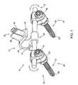
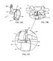
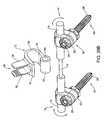
- FIG. 1illustrates an exemplary embodiment of an interspinous lumbosacral stabilization device according to this invention
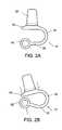
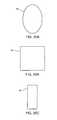
- FIGS. 2A-2Bprovide side views of a spacer body under resting and compressed states, respectively, according to exemplary disclosed embodiments
- FIGS. 3A-3Cprovide side views of a spacer body having varying thickness along its length, according to exemplary disclosed embodiments
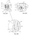
- FIG. 4Aprovides a perspective view of a spacer body having a variable width along its length, according to another exemplary disclosed embodiment
- FIG. 4Bprovides a rear view of the spacer body of FIG. 4A ;
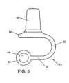
- FIG. 5provides a side view of a spacer body, according to an exemplary disclosed embodiment
- FIGS. 6A-6Cprovide rear views of a spacer body, according to exemplary disclosed embodiments.
- FIG. 7Aprovides a rear view of a spacer body including barbs, according to an exemplary disclosed embodiment
- FIG. 7Bprovides a side view of a spacer body including barbs, according to an exemplary disclosed embodiment
- FIG. 8Aprovides a partial top-down perspective view of a spacer body including curved lateral walls, according to an exemplary disclosed embodiment
- FIG. 8Bprovides an enlarged view showing details of FIG. 8A ;
- FIG. 9Aprovides a partial perspective view of a spacer body including curved lateral walls, according to an exemplary disclosed embodiment
- FIG. 9Bprovides a partial perspective view of the spacer body of FIG. 9A implanted within a patient
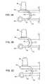
- FIG. 10Aprovides a partial perspective view of a spacer body having a detachable lateral wall, according to an exemplary disclosed embodiment
- FIGS. 10B and 10Cprovide partial perspective views of the spacer body of FIG. 10A implanted within a patient;
- FIG. 11Aprovides a partial perspective view of a spacer body having a detachable lateral wall, according to an exemplary disclosed embodiment
- FIGS. 11B and 11Cprovide partial perspective views of the spacer body of FIG. 11A implanted within a patient;
- FIG. 12Aprovides a partial perspective view of a spacer body having a detachable lateral wall, according to an exemplary disclosed embodiment
- FIGS. 12B and 12Cprovide partial perspective views of the spacer body of FIG. 12A implanted within a patient;
- FIG. 13Aprovides a partial perspective view of a spacer body having a hinged lateral wall, according to an exemplary disclosed embodiment
- FIGS. 13B and 13Cprovide partial perspective views of the spacer body of FIG. 13A implanted within a patient;
- FIG. 14Aprovides a partial exploded view of a spacer body having a foldable lateral wall, according to an exemplary disclosed embodiment
- FIGS. 14B and 14Cprovide partial perspective views of the spacer body of FIG. 14A implanted within a patient;
- FIG. 14Dprovides an enlarged view showing details of FIG. 14C ;
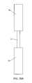
- FIG. 15provides a side view of a bone fastener, according to an exemplary disclosed embodiment
- FIG. 16Aprovides a cross-sectional view of the bone fastener of FIG. 16C , according to an exemplary disclosed embodiment
- FIG. 16Bprovides an enlarged view showing details of FIG. 16A ;
- FIG. 16Cprovides a side view of the bone fastener of FIG. 16A ;
- FIG. 16Dprovides an enlarged view showing details of FIG. 16C .
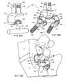
- FIG. 17Aprovides a perspective view of a spacer body and flexible fixation member, according to an exemplary disclosed embodiment
- FIG. 17Billustrates the device of FIG. 17A positioned between an L5 spinous process and a sacrum, according to an exemplary disclosed embodiment
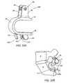
- FIG. 18Aprovides a partial perspective view of a spacer body having a rigid fixation member, according to an exemplary disclosed embodiment
- FIG. 18Bprovides an enlarged view showing details of FIG. 18A ;
- FIG. 18Cprovides a partial perspective view of the spacer body of FIG. 18A implanted within a patient
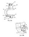
- FIG. 19Aprovides a partial perspective view of a spacer body having a rigid fixation member, according to an exemplary disclosed embodiment
- FIG. 19Bprovides an enlarged view showing details of FIG. 19A ;
- FIG. 19Cprovides a partial perspective view of the spacer body of FIG. 19A implanted within a patient;
- FIG. 20Aprovides a partial perspective view of a spacer body having a rigid fixation member, according to an exemplary disclosed embodiment
- FIG. 20Bprovides an enlarged view showing details of FIG. 20A ;
- FIG. 20Cprovides a partial perspective view of the spacer body of FIG. 20A implanted within a patient;
- FIG. 21provides a side view of a spacer body, according to another exemplary disclosed embodiment
- FIG. 22Aprovides a side perspective view of a spacer body, according to yet another exemplary disclosed embodiment
- FIG. 22Bprovides a perspective view of the spacer body of FIG. 22A implanted within a patient
- FIG. 23provides a side view of a spacer body, according to a further exemplary disclosed embodiment
- FIG. 24provides a rear view of a spacer body and fixation rod, according to an exemplary disclosed embodiment
- FIGS. 25A-25Cprovide cross-sectional views of fixation rods, according to exemplary disclosed embodiments.
- FIG. 26Aprovides a front view of a fixation rod, according to another exemplary disclosed embodiment
- FIG. 26Bprovides an exploded perspective view of a spacer body and the fixation rod of FIG. 26A , according to an exemplary disclosed embodiment
- FIGS. 27A-27Cillustrate front views of alternate fixation rods, according to exemplary disclosed embodiments
- FIG. 28Aprovides a perspective view of a spacer body, according to an exemplary disclosed embodiment
- FIG. 28Bprovides a perspective view of a device including the spacer body of FIG. 28A , implanted in a patient;
- FIG. 29Aprovides an exploded view of a spacer body and rod, according to an exemplary disclosed embodiment
- FIG. 29Bprovides a perspective view of a device including the spacer body and rod of FIG. 29A ;
- FIG. 29Cprovides a partial cross-sectional view of the device of FIG. 29B implanted in a patient
- FIG. 30provides an exploded perspective view of a polyaxial screw system, according to an exemplary disclosed embodiment
- FIG. 31Aprovides a cross-sectional view of the polyaxial screw system of FIG. 30 along lines A-A;
- FIG. 31Bprovides a cross-sectional view of the polyaxial screw system of FIG. 30 along lines B-B;
- FIG. 31Cprovides an enlarged view showing details of FIG. 31A ;
- FIG. 31Dprovides an enlarged view showing details of FIG. 31B ;
- FIG. 32Aprovides a side perspective view of a spacer body, according to an exemplary disclosed embodiment
- FIG. 32Bprovides a partial side perspective view of the spacer body of FIG. 32A implanted in a patient;
- FIG. 33Aprovides a side perspective view of a spacer body, according to an exemplary disclosed embodiment
- FIG. 33Bprovides a partial side perspective view of the spacer body of FIG. 33A implanted in a patient;
- FIG. 34Aprovides a side perspective view of a spacer body, according to an exemplary disclosed embodiment
- FIG. 34Bprovides a partial side perspective view of the spacer body of FIG. 34A implanted in a patient
- FIG. 35Aprovides a side perspective view of a spacer body, according to an exemplary disclosed embodiment
- FIG. 35Bprovides a partial side perspective view of the spacer body of FIG. 35A implanted in a patient
- FIG. 36Aprovides a side perspective view of a spacer body, according to an exemplary disclosed embodiment
- FIG. 36Bprovides a partial side perspective view of the spacer body of FIG. 36A implanted in a patient;
- FIG. 37Aprovides a side perspective view of a spacer body, according to yet another exemplary disclosed embodiment
- FIG. 37Bprovides a partial side perspective view of the spacer body of FIG. 37A implanted in a patient;
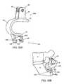
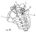
- FIG. 38Aprovides an exploded perspective view of a spacer body, according to another exemplary disclosed embodiment
- FIG. 38Bprovides a side perspective view of the spacer body of FIG. 38A assembled
- FIG. 39provides a perspective view of the spacer body of FIGS. 38A and 38B implanted in a patient;
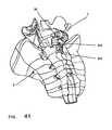
- FIG. 40Aprovides an exploded perspective view of a spacer body, according to yet another exemplary disclosed embodiment
- FIG. 40Bprovides a side perspective view of the spacer body of FIG. 40A assembled.
- FIG. 41provides a perspective view of the spacer body of FIGS. 40A and 40B implanted in a patient.
- the implant or device 10comprises a spacer body 12 that is configured to be implanted between the spinous process of a lumbar vertebra, such as the fifth lumbar (L5) spinous process, and an adjacent vertebra.
- An anchor assembly 14is provided to secure the spacer body 12 to the adjacent vertebra, which can be, for example, the first sacral vertebra (S1).
- the anchor assembly 14may include a support or a fixation rod 16 to help maintain the spacer body 12 in a proper position with respect to the spine.
- One or more fixation elementssuch as, for example, bone anchors 18 may be used to firmly attach the support or fixation rod 16 onto the patient's sacrum.
- the spacer body 12may be connected to the fixation rod 16 at a base portion 62 .
- the spacer body 12 , support rod 16 , and bone anchors 18form an interspinous stabilization assembly for stabilizing a lumbar vertebra such as the fifth lumbar vertebra (L5) adjacent the sacrum.
- the spacer body 12may have various shapes, thicknesses, and materials.
- the spacer body 12may include a midsection 30 extending between an inferior section 32 and a superior section 34 , as shown in FIG. 1 .
- the superior section 34is configured to contact a portion of a spinous process, while the inferior section 32 is configured to connect with fixation rod 16 .
- the midsection 30 , inferior section 32 , and superior section 34may together form a substantially U-shaped spacer body 12 .
- the spacer body 12may be configured to be flexible and/or bendable, such as, for example, by providing an extendable and/or compressible midsection 30 .
- a spinous processmay exert an inferiorly-directed force on the superior section 34 .
- the fixation rod 16 and/or sacrummay exert a superiorly-directed force on the inferior section 32 .
- these forcesmay cause the superior section 34 and the inferior section 32 to be brought closer together ( FIG. 2B ) from a resting state in which no external force acts upon the spacer body 12 ( FIG. 2A ). Compressibility in this way may allow the spacer body 12 to reversibly deform to allow some degree of spinal extension.
- the midsection 30acts as a flexible hinge, allowing the superior section 34 and inferior section 32 to move away from or towards one another.
- the thickness and physical properties of the superior section 34 and/or the inferior section 32may be selected to allow the superior section 34 and/or the inferior section 32 to bend under ample load. Flexibility (i.e., extendability and/or compressibility) may allow the spacer body 12 to better respond to some normal patient movements. For example, a spacer body 12 having limited compressibility may allow a certain degree of spinal extension, while also controlling spinal flexion, rotation, and/or lateral bending.
- spacer body 12may be selected based on the body habitus of the patient in whom the device 10 is to be implanted, based on the desired range of motion, and based on various clinical factors. Such clinical factors may include co-morbid conditions, extent of disease, prior surgery, etc. For some patients, a very rigid spacer body 12 may be desirable. For other patients, a more flexible and compressible spacer body 12 may be selected by the surgeon.
- the flexibility and/or compressibility of the spacer body 12may be controlled in a number of ways.
- the spacer body 12may be formed from a variety of different materials.
- the spacer body 12may be formed from a single material.
- the spacer body 12may include a combination of materials such that the materials forming the midsection 30 , inferior section 32 , and superior section 34 can differ to provide each of the sections with varying degrees of flexibility and/or compressibility.
- the specific materials included in each section of the spacer body 12may be selected based on a desired degree of flexibility and/or compressibility or to provide biocompatibility and/or bioactive characteristics.
- the spacer body 12may be formed from a medical grade metal such as titanium or titanium alloy.
- the spacer body 12may also be formed from, e.g., stainless steel, cobalt chrome, ceramics, and/or polymeric materials, such as ultra-high molecular-weight polyethylene (UHMWPE) and polyetheretherketone (PEEK), either alone or in combination with another one of the suitable materials.
- UHMWPEultra-high molecular-weight polyethylene
- PEEKpolyetheretherketone
- Another way to provide flexibility and/or compressibility to the spacer body 12is to vary the dimensions of the spacer body 12 , such that the degree of flexibility relates to the relative dimensions of the spacer body 12 .
- the spacer body 12may have a variety of different thicknesses along its length. The thicknesses may be selected to produce a desired degree of flexibility and compressibility.
- the spacer body 12may have a variable thickness in one or more different sections.
- FIGS. 3A-3Cillustrate a variety of thickness configurations for the spacer body 12 , in which the midsection 30 has a thickness t 1 , the inferior section 32 has a thickness t 2 and the superior section 34 has a thickness t 3 .
- thickness t 1 , thickness t 2 , and thickness t 3may be approximately equal ( FIG. 3A ). In another embodiment, thickness t 1 may be greater than thicknesses t 2 and t 3 ( FIG. 3B ), and in still another embodiment, thickness t 1 may be less than thicknesses t 2 and t 3 ( FIG. 3C ). Hence, as shown in FIGS. 3B and 3C , the thickness and consequently the flexibility of the spacer body 12 can vary along its length.
- the spacer body 12can have a width at the midsection 30 that is less than the width of either the inferior section 32 or superior section 34 .
- Such a configurationwould provide the spacer body 12 with an hourglass-like configuration, when viewed from the rear as shown in FIG. 4B .
- a bearing cushion(not shown) can be placed between the superior 34 and inferior sections 32 within the spacer body 12 .
- the bearing cushioncan be similar to the one described in U.S. Pat. No. 5,645,599 to Samani, the contents of which are hereby incorporated in its entirety by reference.
- the bearing cushionmakes it possible to limit the closing together of the two sections 32 , 34 and to ensure a supplementary cushioning of the vertebra 4 if such is desired.
- the cushioncan be made of a suitable elastic material, either woven material or synthetic material, and can be fixed to the sections 32 , 34 by any suitable means, such as for example by adhesive bonding.
- the spacer body 12may be provided with a pair of lateral walls or brackets 36 that extend from the superior section 34 , as shown in FIG. 5 .
- the pair of lateral walls 36defines a stirrup 38 for receiving a spinous process.
- the lateral walls or brackets 36may be configured to engage the spinous process of a lumbar vertebra near the sacrum and secure the spacer body 12 to the spinous process.
- the brackets 36may be configured to engage the spinous process of the fifth lumbar vertebra (L5) adjacent the sacrum.
- the lateral walls 36may have a number of orientations with respect to the spacer body 12 .
- lateral walls 36may extend in a variety of angles with respect to the superior section 34 .
- the lateral walls 36may form a 90 degree angle with respect to the superior section 34 ( FIG. 6A ).
- the lateral walls 36may form an obtuse angle ( FIG. 6B ) or an acute angle ( FIG. 6C ) with respect to the superior section 34 .
- spacer bodies 12can be provided with lateral walls 36 of various sizes or heights to accommodate a variety of different interspinous spaces between vertebrae.
- the lateral walls 36 of different spacer bodies 12may be provided at different locations along the length of the superior sections 34 , in order to provide a greater variety of sizes and shapes. The surgeon can thus select a suitably shaped and sized spacer body 12 depending on the particular vertebra to be supported and the natural anatomy of the patient.
- the lateral walls 36may also be adjustable with respect to the spacer body 12 .
- the lateral walls 36may form an obtuse angle with respect to the superior section 34 before implantation.
- the lateral walls 36may be formed of a malleable material such that, after implantation, the surgeon may compress the lateral walls 36 together to reduce the gap between the lateral walls 36 , thereby securely fixing the spacer body 12 to the spinous process of the vertebra. The compression may be accomplished, for example, by pinching or squeezing the lateral walls 36 towards one another using surgical pliers or forceps.
- the device 10may include a number of surface modifications.
- sections of the spacer body 12 , lateral walls 36 , anchors 18 , and/or fixation rod 16may include surface alterations that may facilitate tissue attachment, bonding or fixation. These alterations may include surface teeth, barbs, beads, surface roughening, or the addition of bioactive agents to one or more sections of the device 10 .
- the device 10may include one or more barbs 40 for securing the device 10 to bone and/or soft tissue. As shown in FIGS.
- barbs 40may be located on the spacer body 12 , such as on an outer surface of the midsection 30 , inferior section 32 and/or superior section 34 ( FIG. 7B ). Alternatively, or in addition, the barbs 40 may be located on an inner surface of the lateral walls 36 ( FIG. 7A ). The barbs 40 may help the spacer body 12 securely engage connective tissue or a bony surface of a vertebra, such as the spinous process of the vertebra.
- the device 10may also include roughened or porous surfaces.
- the roughened or porous surfacesmay enhance attachment between implant surfaces and bone tissue.
- some porous surfacesmay facilitate tissue ingrowth to form a biological bond between sections of the device 10 and the surrounding bone and/or soft tissue.
- Roughened or porous surfacesmay be included on any portion of the device 10 , including the spacer body 12 , anchors 18 , lateral walls 36 , and/or fixation rod 16 .
- the surface of the device 10may also include biologically active agents. These agents may include osteogenic factors to further facilitate bonding between components of the device 10 and the surrounding bone and/or soft tissue. Further, the device 10 may include therapeutic agents such as antibiotics, steroids, anti-thrombotic agents, anti-inflammatory drugs, and/or analgesic agents. In one embodiment, the biologically active agent may be contained in a coating on the device. Alternatively, or in addition, the device may be porous and the biologically active agent may be contained in the pores of the device. The biologically active agent may be, for example, bone morphogenic protein (BMP) for inducing cartilage or bone growth.
- BMPbone morphogenic protein
- the lateral walls 36may be curved or angled with respect to the longitudinal axis L of the spacer body 12 .
- FIGS. 8A and 8Bshow lateral walls 36 that curve away from the longitudinal axis L of the spacer body 12 along the length of the lateral walls 36 .
- the lateral walls or brackets 36can also be bent or curved inwards or outwards along their length with respect to the longitudinal axis L of the spacer body 12 to accommodate the patient's natural anatomical curves of the laminae.
- FIG. 9Aillustrates a spacer body 12 having lateral walls 36 that bend inward with respect to the longitudinal axis L of the spacer body 12 .
- Such curved brackets 36allow even greater conformity around the spinous process 2 , and therefore better fixation of the device 10 to the vertebra 4 , as shown in FIG. 9B .
- At least one of the lateral walls or brackets 36may be removably attachable to the spacer body 12 .
- one of the pair of lateral walls or brackets 36 Acan be formed as an attachable element to the spacer body 12
- the other lateral wall or bracket 36 Bis permanently affixed or integral with the spacer body 12 .
- the attachable bracket 36 Bcan include a first free end 42 and an opposed, second attachment end 44 that is shaped to complement a slot or groove 46 on the superior section 34 , thereby forming a secure connection with the spacer body 12 .
- the attachment end 44can be formed as a flared end or dovetail for sliding engagement with a dovetail groove 46 on the superior section 34 once the spacer body 12 has been implanted in position.
- FIGS. 11A-11Cshow an attachable bracket 36 A having an attachment end 44 shaped as a “T” for sliding engagement with a T-shaped groove 46 on the superior section 34 of the spacer body 12 .
- the attachable bracket 36 Acan slide onto a groove 46 which is formed on a side surface of the superior section 34 . For example, as shown in FIGS.
- the attachment end 44 of bracket 36 Ais configured as a dovetail to slidingly engage a dovetail groove 46 on a side surface of superior section 34 of spacer body 12 .
- attachment end 44has been described hereinabove as having a dovetail or T-shaped configuration, it is understood that the attachment end 44 can include other shapes known to one skilled in the art for forming a secure attachment to a complementarily shaped groove 46 on the superior section 34 .
- the spacer body 12can include a movable, pivotable bracket 36 A which can be hinged to the superior section 34 .
- the second, attachment end 46 of bracket 36 Acan include an aperture 48 for placement of a pin 50 therethrough to pivotably secure the bracket 36 A to a side surface of superior section 34 .
- the pivotable bracket 36 Acan be folded down ( FIG. 13A ) prior to implantation and then after the spacer body 12 has been placed in its correct position, the pivotable bracket 36 A can be folded up to rest against and engage the spinous process 2 of the vertebra 4 , as shown in FIGS. 13B and 13C .
- the movable, adjustable bracket 36 Acan be hinged to the superior section 34 of the spacer body, as shown in FIG. 14A .
- the movable bracket 36 Acan be attached to the spacer body 12 by a hinge joint 52 that allows the bracket 36 A to fold up and down. This foldability allows the bracket 36 A to move between a position in which the movable bracket 36 A is substantially perpendicular to the respective adjacent bracket 36 B ( FIG. 14A ), and a position in which the movable bracket 36 A is substantially parallel to the adjacent bracket 36 B ( FIGS. 14B and 14C ) to engage the spinous process 2 .
- the lateral walls or brackets 36 of the present inventioncan also include an aperture 60 for receiving a bone screw, fastener or rivet to fix the brackets 36 to the spinous process 2 .
- Such fastening memberswould ensure that the brackets 36 are laid flat against the spinous process 2 in order to avoid any play of the process with respect to the brackets 36 .
- each of the brackets 36 A, 36 Bcan be provided with an aperture 60 configured to receive a rivet or fastener 100 , shown in greater detail in FIG. 15 .
- the rivet 100can include a cap 102 , an elongate body 104 extending from the cap 102 , the elongate body 104 including a plurality of teeth 108 and terminating at a tapered distal end 106 .
- the elongate body 104is configured to extend between the apertures 60 of the brackets 36 A, 36 B.
- a washer 120can be provided to maintain the rivet 100 within the apertures 60 .
- the washer 120includes an aperture 122 for receiving the tapered distal end 106 of the rivet 100 . Slots 124 around the aperture 122 enable the washer 120 to flex so that the tapered distal end 106 can be pushed through the aperture 122 and the washer 120 to close around the teeth 108 of the rivet 100 .
- FIGS. 16A-16Dillustrate another exemplary embodiment of a bone fastener or pin 140 suitable for use with the brackets 36 of the present invention.
- Fastener 140includes a head 142 , an elongate body 144 having teeth 148 extending thereabout to a distal end 146 .
- a cap 160is provided which has a head 162 and a body 164 extending therefrom for receiving the distal end 146 of the fastener 140 .
- the hollow body 164can include one or more U-shaped slots 166 , with each slot 166 defining a finger projection 168 therein.
- Each of the finger projections 168has a curved end portion 170 bent towards the central axis of the hollow body 164 for engaging the teeth 148 of the fastener 140 , as illustrated in FIG. 16A and in greater detail in FIG. 16B .
- the cap 160includes two pairs of finger projections 168 , with each pair being diametrically opposed.
- the pairs of finger projections 168can be staggered with respect to the longitudinal axis A-A of the cap 160 , thereby providing a more controlled level of attachment by providing two distinct areas within the slotted cavity 166 for capturing the teeth 148 of the fastener 140 .
- the cap 160is placed through the aperture 60 of the bracket 36 and then pushed towards the fastener 140 in a ratchet-like fashion until the heads 142 , 162 of the fastener 140 and cap 160 are flush with the outer surface of the brackets 36 , locking together the fastener 140 and cap 160 and thereby also providing an overall smooth outer surface that prevents trauma or injury to the nearby soft or bony tissue.
- brackets 36 of the spacer body 12may be used with one or more flexible fixation elements to further secure the device 10 to one or more spinous processes.
- the lateral walls or brackets 36 of flexible spacer body 12may include one or more apertures 60 for attaching a flexible fixation element 180 .
- the flexible fixation element 180may include synthetic or natural materials.
- the flexible fixation element 180may include any type of synthetic or natural suture material.
- the flexible fixation element 180may also include grafts of ligaments, tendon, fascia, or muscle, and the grafts may include autografts, allografts, or xenografts having sufficient strength and pliability to tie around a spinous process of a vertebra, such as for example, a lumbar vertebra.
- the flexible fixation elementmay be a woven fabric, mesh, or webbing such as a cable-binder type strap for placement around the spinous process.
- FIG. 17Billustrates the spacer body 12 implanted between a sacrum 8 and spinous process 2 of an adjacent vertebra 4 , while the fixation rod 16 is secured to the sacrum 8 using two anchors 18 .
- the lateral walls 36further secure the spacer body 12 to the spinous process 2 of the vertebra.
- the device 10includes a flexible fixation element 180 , which may further secure the device 10 to the spinous process 2 .
- a rigid fixation elementmay be used to secure the spacer body to the spinous process.
- a stabilization device 200is provided which may include a rigid fixation element comprising a rigid fixation cap 220 for placement over a portion of the spacer body 202 .
- the spacer body 202may be similar to spacer body 12 but without the lateral walls 36 .
- the fixation cap 220may be U-shaped, and include a pair of sidewalls 222 , the terminal ends 224 of which include a lip 226 defining a groove 228 for sliding engagement with a flange 206 on the superior section 204 of the spacer body 202 to securely attach the spacer body 202 to a spinous process 2 , as shown in FIG. 18C .
- the fixation cap 220can include barbs 210 for secure engagement with the bony surface of the spinous process, thereby ensuring a rigid fixation.
- FIGS. 19A-19Cillustrate yet another exemplary embodiment wherein a stabilization device 240 is provided with a rigid fixation element comprising a fixation cap 260 for placement over a portion of the spacer body 242 .
- the fixation cap 260may be U-shaped, and include a pair of sidewalls 262 , the terminal ends 264 of which include a beveled flange 266 .
- the spacer body 242does not include lateral walls 36 . Instead, the spacer body 242 can include slots 246 on the superior section 244 . Due to the slight flexibility and compressibility of the sidewalls 262 , the beveled flanges 266 can be forced down and through the slots 246 , as shown in FIGS. 19A and 19B to engage the spacer body 242 .
- the fixation cap 260can include barbs 210 for secure engagement with the bony surface of the spinous process, thereby ensuring a rigid fixation.
- FIGS. 20A-20Cillustrate an exemplary embodiment in which the spacer body 12 of the present invention can be used with a rigid fixation element.
- a rigid fixation cap 280is provided for use with the spacer body 12 of the present invention.
- the rigid fixation cap 280includes a pair of sidewalls 282 connected by a connector section 284 .
- Sidewalls 282include teeth 288 on an inside surface that can engage a notch 63 on an outer surface on the lateral walls or brackets 36 of spacer body 12 .
- the fixation cap 280can be placed over the brackets 36 after the spacer body 12 is in position and the vertebra's spinous process 2 resides securely within the stirrup 38 defined by the brackets 36 .
- the teeth 288 within the sidewalls 282can ratchet over and lock with the notches 63 of the brackets 36 until the connector section 284 of the cap 280 rests against the spinous process 2 , and thereby ensures a secure fit between the bony tissue and the device 10 , as illustrated in FIG. 20C .
- the adjustability of the fixation cap 280allows the spacer body 12 to secure a variety of sized spinal processes.
- the lateral walls or brackets 36can be provided with elongated slots 60 similar to the elongated slots 290 on the sidewalls 282 of the fixation cap 280 .
- the slots 60 , 290align and cooperate to provide an opening for placement of an optional fixation element therethrough for further securement of the spinous process to the spacer body 12 , if desired.
- the fixation elementcan be, for example, a bolt or bone screw that extends through the spinous process or extends atop the process and across the two sidewalls 282 .
- the fixation caps 220 , 260 , 280may be formed from a variety of different biocompatible metals materials, such as, for example, titanium and stainless steel, or cobalt chrome, or biocompatible plastics, either alone or along with at least one other suitable material from this group.
- the shape, dimensions, and materials of the fixation caps 220 , 260 , 280may be selected to control their physical properties such as flexibility, strength, and/or fracture resistance.
- the spacer body 12may connect with the fixation rod 16 at a base portion 62 extending from the inferior section 32 .
- the base portion 62may form a permanent connection or a removable connection.
- the spacer body 12may include an aperture 64 within the base portion 62 for engaging the fixation rod 16 .
- the aperture 64may be a through hole for placement of the fixation rod 16 therethrough.
- a plastic linercan be provided within the aperture 64 of the base portion 62 to facilitate a smooth, sliding movement of the rod 16 within the aperture 64 .
- the plastic linercan be formed from, for example, a polyethylene, such as ultra high molecular weight polyethylene (UHMWPE), or polyetheretherketone (PEEK).
- UHMWPEultra high molecular weight polyethylene
- PEEKpolyetheretherketone
- the base portion 62may comprise a semi-circular or C-shaped section 66 for engaging the fixation rod 16 .
- the C-shaped section 66can be configured to be snap fitted onto the rod 16 .
- a plastic linerformed from, for example, a polyethylene, such as ultra high molecular weight polyethylene (UHMWPE) or polyetheretherketone (PEEK) can be provided on the rod 16 between the C-shaped section 66 in order to provide smooth gliding motion of the spacer body 12 against the rod 16 .
- UHMWPEultra high molecular weight polyethylene
- PEEKpolyetheretherketone
- the spacer body 12may be configured to be angularly rotatable with respect to the longitudinal axis of the fixation rod 16 .
- the spacer body 12may be freely rotatable with respect to the longitudinal axis of the fixation rod 16 .
- the fixation rod 16may include one or more protrusions 68 for limiting the rotation of the spacer body 12 , as illustrated in FIG. 23 .
- the spacer body 12may rotate between about 0 and about 60 degrees with the protrusion 68 delimiting the space between which the spacer body 12 can rotate. Such rotation may facilitate positioning of the spacer body 12 during implantation, while also allowing a controlled degree of patient motion after implantation.
- surgeonmay select the degree of rotation available by selecting a fixation rod 16 with a protrusion 68 having a predetermined size and shape.
- the spacer body 12may be rigidly fixed to the fixation rod 16 so as not to allow any rotation.
- the spacer body 12may also be configured to be laterally movable or slidable with respect to the fixation rod 16 .
- the fixation rod 16may include one or more lateral protrusions 70 to delimit the space within which the spacer body 12 can slide.
- the lateral protrusions 70may limit lateral displacement of the spacer body 12 when attached to the fixation rod 16 .
- the lateral protrusions 70may be adjustably positioned on the fixation rod 16 , thereby allowing the surgeon to select a desired degree of lateral displacement.
- the lateral protrusions 70may be positioned adjacent the spacer body 12 to prevent any lateral movement of the spacer body 12 with respect to the fixation rod 16 .
- fixation rod 16may be configured to limit lateral movement of the spacer body 12 (as shown in FIGS. 26A and 26B ).
- the fixation rod 16may be configured to have a number of different shapes, sizes, and/or material properties.
- the fixation rod 16is a straight rod with a circular cross-section.
- FIGS. 25A-25Cillustrate additional cross-sectional geometries suitable for the fixation rod 16 of the present disclosure.
- the fixation rod 16may have an oval cross-section ( FIG. 25A ), a square cross-section ( FIG. 25B ), or a rectangular cross-section ( FIG. 25C ).
- the fixation rod 16may have a cross-sectional geometry that is variable across its length.
- the fixation rod 16may include a connecting region 74 for engaging the base portion 62 of the spacer body 12 .
- the connecting region 74may be thicker or thinner (as shown in FIGS. 26A and 26B ) than the surrounding thicker sections 76 of the fixation rod 16 .
- the fixation rod 16may be configured to limit lateral movement of the spacer body 12 .
- the fixation rod 16may include a narrow connecting region 74 .
- the spacer body 12may be connected to the fixation rod 16 at the narrow connecting region 74 by engaging the base portion 62 thru the aperture 64 .
- the surrounding thicker sections 76may thereby block lateral movement of the spacer body 12 on the fixation rod 16 , while still allowing rotation of the spacer body 12 with respect to the fixation rod 16 .
- the spacer body 12may be fused to the fixation rod 16 to prevent lateral movement and/or rotation with respect to the fixation rod 16 .
- the fixation rod 16may be formed from a variety of different biocompatible materials.
- the fixation rod 16may, e.g., be formed from titanium, stainless steel, ceramics, or cobalt chrome, either alone or along with at least one other suitable material from this group.
- the fixation rod 16may comprise the same materials as the spacer body 12 or different materials than the spacer body 12 .
- the shape, dimensions, and materials of the fixation rod 16may be selected to control the flexibility, strength, and/or fracture resistance of the fixation rod 16 .
- the length and thicknessmay also be selected based on a patient's size, disease characteristics, and/or activity level.
- the fixation rod 16may be straight, bent, or curved along its length to accommodate the natural curves of the patient's anatomy.
- the fixation rod 16may include at least one curved section 80 ( FIG. 27A ).
- the fixation rod 16may include at least two bent sections 78 ( FIG. 27B ).
- the bent sections 78may be formed at an angle a with respect to a longitudinal axis of the fixation rod 16 .
- the angle amay be between 0 and 90 degrees.
- the angle amay be about 30 degrees ( FIG. 27B ) or about 90 degrees ( FIG. 27C ).
- the fixation rod 16 having a curved 80 or bent section 78may be implanted in a number of different anatomic orientations.
- the bent section 78may be positioned in a superior-anterior orientation with respect to the longitudinal axis of the fixation rod 16 .
- the exact orientationmay be selected based on surgical factors and/or patient anatomy.
- FIGS. 28A and 28Bprovide such an exemplary embodiment, in which the spacer body 12 ′ includes an elongate or oval base portion 84 with a corresponding elongate or oval aperture 86 for use with a cylindrical rod 16 of the present invention.
- spacer body 12 ′is similar to spacer body 12 previously described, whereby similar features are designated by the same reference numerals.
- a plastic liner 88can be provided within the aperture 86 .
- the plastic linercan be formed from any suitable plastic, such as, for example, ultra high molecular weight polyethylene (UHMWPE) or polyetheretherketone (PEEK).
- UHMWPEultra high molecular weight polyethylene
- PEEKpolyetheretherketone
- FIGS. 29A-29Cillustrate yet another exemplary embodiment of a spacer body 12 ′′ which can translate about the anterior-lateral direction with respect to the fixation rod 16 ′′.
- the spacer body 12 ′′includes an inferior section 32 having a raised socket 90 defining a spherical groove or cavity thereunder 92 .
- the spherical cavity 92is configured to sit against a spherical protrusion or knob 94 on fixation rod 16 ′′.
- the spacer body 12 ′′ and the fixation rod 16 ′′are similar to the spacer body 12 and fixation rod 16 previously described, whereby similar features are designated by the same reference numerals.
- the raised socket 90is positioned over and sits on the spherical protrusion or knob 94 , creating a ball-and-socket type joint.
- Such a connectionwould allow the spacer body 12 ′′ to rotate freely with respect to the rod 16 ′′ and thereby provide the patient with even greater flexibility and degree of motion, especially during twisting or bending movements, but still providing a rigid, fixed attachment to the vertebra being supported.
- fixation elementsmay be provided.
- the fixation elementsmay include anchors 18 that attach to the fixation rod 16 at one or more anchor-connecting regions 110 .
- Anchor-connecting regions 110may include protrusions, as illustrated in FIG. 30 . Additionally, the anchor-connecting regions 110 may comprise indentations, concavities, convexities, or anchor through-holes, as shown in FIG. 22B .
- the design of anchor-connecting regions 110may be selected based on the design of the particular type of anchor 18 being used. It is contemplated that the design and type of anchor 18 can vary without departing from the spirit of the present disclosure.
- the anchors 18may include any type of screw that may securely engage bone.
- the anchor 18may comprise a polyaxial screw, which may be aligned in a range of angular orientations with respect to the fixation rod 16 .
- the polyaxial screwsmay allow the surgeon to easily adjust the position of the screw during surgery and consequently the fixation rod 16 based on anatomic variances of the patient.
- the anchor 18can be similar to the one disclosed in U.S. Pat. No. 6,554,831 to Rivard, which is hereby incorporated in its entirety by reference.
- the polyaxial screw 20is captured within a C-shaped collar such as clamp collar 22 that fits around the fixation rod 16 .
- the screw 20can include a proximal threaded portion 24 that extends through the collar 22 and is fixed in place by tightening nut 26 , and a distal threaded portion 28 that enables the screw 20 to anchor to bone tissue.
- FIGS. 30 , 31 A and 31 BAn exemplary embodiment of a polyaxial screw 300 suitable for use with the present invention is shown in FIGS. 30 , 31 A and 31 B.
- the polyaxial screw 300includes an elongated threaded body 302 extending between a head portion 304 and a distal end 306 .
- the threaded body 302can be straight or angled or curved, depending on the particular need of the patient.
- the head portion 304includes a hollow spherical cavity 308 for receiving an anchor-connecting element, which in this embodiment takes the form of a spherical clamp ring 320 .
- the spherical clamp ring 320includes slots 322 distributed around its periphery to enable the clamp ring 320 to flex and slidingly fit over a fixation rod 16 .
- the head 304also includes a plurality of spherical undercuts 328 , creating curved inclined walls, and slots 326 extending therein at the bottom of the cavity 308 , which are disposed so that they are substantially radial in relation to the cavity 308 .
- These slots 326 and undercuts 328converge toward one another in the direction of the bottom of the cavity 308 and give a slight flexibility to the head 304 .
- the undercuts 328enable the slotted spherical clamp ring 320 to snap on inside the hollow spherical cavity 308 .
- Two threaded holes 330are also provided on the head portion 304 for receiving threaded screws 318 .
- a locking cap 310is provided which comprises screw holes 312 for receiving the threaded screws 318 .
- the screw holes 312coincide with the holes 330 on the head portion 304 .
- the locking cap 310also includes a hollow cavity 314 suitably shaped to receive a portion of the spherical clamp ring 320 , as illustrated in FIG. 31A .
- the hollow cavity 314can have a cone shape, permitting the cap 310 to come into contact with the spherical clamp ring 320 in the course of tightening the screws 318 .
- the hollow cavity 314can also include lateral undercuts and slots similar to those present in the spherical cavity 308 of the head portion 304 to enable the screw 300 to adjust angularly prior to being locked together, as shown in FIG. 31B .
- the spherical clamp ring 320is snap-fitted onto the hollow cavity 308 of the head portion 304 of the screw 300 , the clamp ring 320 being held by the engagement of the slots 322 of the clamp ring 320 and the undercuts 328 of the head portion 304 .
- the clamp ring 320 with the head portion 304 and threaded body 302is then slid over the fixation rod 16 and positioned at an anchor-connecting region of the rod 16 .
- the cap 310is then positioned over the clamp ring 320 and the threaded screws 318 inserted through the screw holes 312 , 330 and tightened. The entire process can be repeated, since a plurality of screws 300 can be used with any given fixation rod 16 , depending on the needs of the patient.
- polyaxial screw 340in FIG. 29B , is shown, but with a modified head portion 344 .
- polyaxial screw 340includes an elongated threaded body 342 extending between a head portion 344 and a distal end 346 .
- the threaded body 342can be straight or angled or curved, depending on the particular need of the patient.
- the head portion 344includes a hollow spherical cavity 348 for receiving an anchor-connecting element, such as, for example, the spherical clamp ring 320 of FIG. 30 .
- the head portion 344can include a plurality of spherical undercuts 352 , creating curved inclined walls, and slots 350 extending therein at the bottom of the cavity 348 .
- a threaded hole 354is also provided on the head portion 344 for receiving a threaded screw 370 .
- a raised flange 356At an opposite end of the head portion 344 is a raised flange 356 which creates a groove 358 for slidingly receiving a locking cap 360 , as shown in FIGS. 29B and 29C .
- Locking cap 360is provided with a lip 372 at one end and at an opposite end a single screw hole 362 for receiving the threaded screw 370 .
- the screw hole 362coincides with the hole 354 on the head portion 344 .
- the lip 372enables the cap 360 to slide over the head portion 344 and engage with the groove 358 prior to insertion of the threaded screw 370 .
- the lip 372 of the locking cap 360 and corresponding groove 358 of the head portion 344can be configured to provide a slight gap or clearance sufficient for the locking cap 360 to be able to flip up to about a 90° angle with respect to the head portion 344 without becoming dislodged, thereby creating a hinge between the cap 360 and the head portion 344 .
- the locking capcan be configured to attach to the head portion via a hinge joint.
- the locking cap 360can also include a hollow cavity 364 suitably shaped to receive a portion of the anchor-connecting element 110 , which hollow cavity 364 can also include lateral undercuts and slots similar to those present in locking cap 310 .
- fixation rod 16can be attached at both ends to a plate 390 having a spherical countersink 392 with a through-hole for insertion of the polyaxial screw 380 therethrough.
- the plate 390can be clamped onto the rod 16 , or it can be configured with an aperture for sliding engagement of the rod 16 into the plate 390 itself.
- the polyaxial screw 380includes an elongate threaded body 382 extending from a spherical head 384 into a distal end 388 .
- the spherical head 384includes a hexagonal opening 386 for receiving an insertion tool (not shown).
- the spherical head 384 of the polyaxial screw 380can be angularly adjustable within the spherical countersink 392 of the plate 390 prior to being secured to bone tissue.
- FIGS. 32A-41provide additional exemplary embodiments of spacer bodies that do not require a rod to be attached to the sacrum.
- a spacer body 400is shown having similar features to the spacer body 12 of previously described embodiments, wherein the same features are designated by the same reference numeral.
- Spacer body 400includes a pair of angled legs 402 extending from the inferior section 32 of the spacer body 400 .
- the legs 402lie in a plane that is substantially parallel to the planes containing the brackets 36 , and can include surface features such as, for example, barbs 404 for engagement with bone tissue.
- the legs 402collectively form an anchor assembly 406 portion comprising a gripping portion 416 for attachment to the sacrum.
- a backplate 410can optionally be provided which extends from the inferior section 32 and lies in a plane that intersects with the planes containing the brackets 36 .
- the legs 402are configured to rest against the median crest of the sacrum 8 , while the backplate 410 rests within the sacral canal and against the sacrum 8 , as shown in FIG. 32B .
- the legs 402 and backplate 410provides a passive bone-engaging region which allows the spacer body 400 to be inserted and secured onto the sacrum without the need for injury or trauma to the bone resulting from screw fixation.
- a spacer body 400 ′is shown having an anchor assembly 406 comprising two backplates 410 extending from the inferior section 32 at an angle away from one another.
- Each of the backplates 410can also be slightly curved along its longitudinal axis.
- FIG. 33Bwhen in use the spacer body 400 ′ rests against the sacrum such that the two backplates 410 rest against the sacrum inside the sacral canal, and legs 402 hook onto the median crest of the sacrum 8 .
- the two backplates 410are configured to provide sufficient clearance between them so as to avoid impinging any nerve tissue contained within the sacral canal once they are inserted into the canal.
- the spacer body 420 of FIG. 34Aincludes an anchor assembly 406 comprising a spike 422 extending from the inferior portion 32 at an angle generally parallel to the legs 402 .
- the spike 422can have a sharp pointed tip, as shown.
- the spike 422is configured to pierce into the sacral bone tissue while the legs 402 engage the median crest, thereby allowing the spacer body 420 to be in position and rest on the sacrum, as illustrated in FIG. 34B .
- the legs 402 of the present embodimentsare shown as plates extending from the spacer body, it is contemplated that the legs 402 can comprise hooks, barbs, jaws, or any suitable gripping element.
- FIGS. 35A and 35Bshow yet another exemplary embodiment of a spacer body 440 which includes an anchor assembly 406 comprising a pair of endplates 432 extending from the inferior section 32 of the spacer body 440 , each endplate 432 having a screw hole 434 for insertion of a screw 436 therethrough.
- the endplates 432can be positioned between the sacral canal and the outer surface of the sacrum, and a screw 436 placed through the bone tissue and secured through the endplates 432 with a nut 438 . It is contemplated that more than one screw 436 may be implemented in the present embodiment.
- the endplates 432may be configured to allow for two or more screws 436 to be placed in any suitable orientation relative to one another, such as in a horizontal or longitudinal row. Alternatively, two or more screws 436 may be inserted through the endplates 432 such that screws 436 flank the median sacral crest.
- the spacer body 440can be provided with two pairs of endplates 432 , with each pair of endplates being configured to grip onto a portion of the sacrum, the two pairs of endplates flanking the median sacral crest.
- the endplates 432may, of course, be provided with any suitable number of screw holes for insertion of bone screws 436 therethrough. Such embodiments would provide rigid and secure fixation of the spacer body 440 to the sacrum.
- FIGS. 36A and 36Bshow an exemplary embodiment in which the spacer body 450 includes a single endplate 452 extending at about a 90° angle with respect to the inferior section 32 of the spacer body 450 .
- the endplate 452can include barbs 404 and a plurality of screw holes 454 for placement of screws 456 therethrough.
- the endplate 452can be configured with a substantially U-shaped body and a pair or more of screw holes 454 extending along the length of each leg of the U. The opening provided by the U-shape allows the endplate 452 to accommodate the spinous process, thereby avoiding the need to resect any part of the bone tissue.
- the endplate 452can take any shape and/or size suitable for placement against a sacral surface, and that any number of screws 456 can be applied in order to achieve a rigid and secure fixation to the bone tissue.
- the endplate 452is configured to rest against the outer surface of the sacrum 8 when the spacer body 450 is in position within the patient, as shown in FIG. 36B .
- FIGS. 37A and 37Bshow still yet another exemplary embodiment in which the spacer body 450 ′ has a detachable endplate 452 .
- the spacer body 450 ′has a shape similar to that shown in FIG. 22A , with the base portion 62 having a C-shaped claw section 66 for snap fitting onto a rod-like attachment end 460 of the detachable endplate 452 .
- Such a configurationwould enable the endplate 452 to be rotatable with respect to the spacer body 450 ′ and thereby provide flexibility for the surgeon during implantation.
- a plastic liner formed from, for example, a polyethylene, such as ultra high molecular weight polyethylene (UHMWPE), or polyetheretherketone (PEEK)can be provided between the rod-like attachment end 460 and the C-shaped section 66 , in order to provide smooth gliding motion of the spacer body 12 against the plate 452 .
- a polyethylenesuch as ultra high molecular weight polyethylene (UHMWPE), or polyetheretherketone (PEEK) can be provided between the rod-like attachment end 460 and the C-shaped section 66 , in order to provide smooth gliding motion of the spacer body 12 against the plate 452 .
- UHMWPEultra high molecular weight polyethylene
- PEEKpolyetheretherketone
- FIGS. 38A and 38Bshow an exemplary embodiment in which the spacer body 500 can include a midsection 30 , inferior 32 and superior 34 sections, and lateral walls or brackets 36 similar to spacer bodies previously described and shown.
- the midsection 30may have varying thickness or dimensions along its length to provide varying physical properties, or may be shaped or curved as shown, in order to better adapt to the anatomical features of the patient.
- the lateral walls or brackets 36may include an aperture 60 for receiving a fastener such as, for example, a rivet.
- the spacer body 500may also include surface alterations such as barbs or teeth 40 , 512 to facilitate tissue attachment, bonding or fixation.
- At least one backplate 410may extend from the inferior section 32 . The backplate 410 may be positioned within the sacral canal and against the sacrum when implanted.
- a side cap or panel 502may be provided for attachment to the spacer body 500 .
- the side cap or panel 502may include a midsection 506 , which may also be similarly shaped and configured as the midsection 30 of spacer body 500 , as well as an inferior section 508 and superior section 504 .
- the inferior section 508may include a groove (not shown) for receiving a tongue 510 extending from the inferior section 32 of the spacer body 500 .
- the inferior section 508may further include grooves 516 for latching to a notch 514 provided on the tongue 510 .
- Legs 402may extend from the inferior section 508 for hooking onto the median crest of the sacrum 8 .
- the superior section 504may include a wedge 518 that rests against the outer surface of the superior section of the spacer body 500 .
- a ramp 520may be provided on the spacer body 500 to limit the extension of the wedge 518 through the brackets 36 .
- the spacer body 500may be first inserted by placing the backplate 410 around the sacrum, and positioning the spinous process 2 of the L5 vertebra in between the lateral walls or brackets 36 .
- the side cap or panel 502may be placed against the spacer body 500 such that the wedge 518 extends under the spinous process and the tongue 510 of the spacer body ratchets into the groove of the cap 502 .
- the legs 402 of the capmay be hooked onto the median crest of the sacrum 8 , as shown in FIG. 39 .
- FIGS. 40A and 40Bshow another exemplary embodiment in which the spacer body 550 can comprise a two-component assembly.
- the first component or top portion 552may include a midsection 30 , a superior 34 section, and lateral walls or brackets 36 similar to spacer bodies previously described and shown.
- the midsection 30may have varying thickness or dimensions along its length to provide varying physical properties, or may be shaped or curved as shown, in order to better adapt to the anatomical features of the patient.
- the lateral walls or brackets 36may include an aperture 60 for receiving a fastener such as, for example, a rivet.
- the spacer body 550may also include surface alterations such as barbs or teeth 40 , 512 to facilitate tissue attachment, bonding or fixation.
- the midsection 30may extend into an inferior platform 580 having a dovetail projection 582 and a groove 584 thereon, as shown in FIG. 40A .
- the second component or bottom portion 554may include a superior platform 570 having a groove 572 thereon and a notch 574 inside the groove 572 to form a dovetail connection with the inferior platform 580 when the first and second components are assembled, as shown in FIG. 40B .
- a backplate 410 and legs 402 similar to those previously shown and describedmay be provided on the second component 554 .
- the second component 554may be placed onto the sacrum 8 , with the backplate 410 resting within the sacral canal and the legs extending around the median crest of the sacrum 8 , as shown in FIG. 41 .
- the first component 552may be secured onto the second component 554 by sliding the dovetail projection 582 into the groove 570 of the first component 552 , and allowing the groove 584 to catch the notch 574 .
- the spinous process 2 of the L5 vertebramay be positioned within the lateral walls or brackets 36 .
- the surgeonmay use the devices of the present disclosure to treat a number of clinical problems.
- the devicesmay be used to treat degenerative disc disease and/or disc herniation.
- the devicesmay also be used to treat spinal stenosis, including central and/or lateral canal stenosis.
- the devicesmay be used before, after, or in conjunction with other treatments or implants, including adjacent rigid fixation, adjacent spinal decompression, fusion, and/or facet replacement or repair.
- the devices of the present disclosuremay be surgically implanted in a variety of ways without impairing the effectiveness of the devices. For example, the surgeon may select a number of different operative approaches and/or incision positions and/or sizes. Further, the surgeon may implant each of the components of the devices in various sequences. The specific operative procedures may be selected based on patient-specific clinical factors.
- a number of different incisions and/or operative proceduresmay be used to implant the devices of the present disclosure.
- the surgeonmay use a mid-line incision over the lumbar and sacral vertebrae to expose the L5-S1 interspinous region.
- the surgeonmay use one or more incisions positioned lateral to the spine.
- the surgeonmay use a minimally-invasive procedure including various scopes, cannula, and/or robotic implantation devices to deliver the devices to the surgical site.
- the components of the devicesmay be implanted using several different steps which may be performed in a number of different sequences. For example, the surgeon may first implant one or more anchors 18 to the sacrum and then implant spacer body 12 in the L5-S1 interspinous space. The spacer body 12 may then be fixed to the fixation rod 16 , which may finally be secured to the sacrum 8 .
- the surgeonmay first implant the spacer body 12 .
- Anchors 18may then be secured to the sacrum and the fixation rod 16 may be secured to the anchors 18 .
- the surgeonmay complete the procedure by securing the device 10 to the spinous process of the vertebra using one or more ligaments, sutures, and/or rigid fixation caps 220 , 260 , 280 .
- the devicesmay be provided in a partially assembled form.
- the spacer body 12may be pre-assembled and securely fixed to the fixation rod 16 .
- the spacer body 12may have a predetermined degree of lateral movement or rotation with respect to the attached fixation rod 16 .
- the devicesmay be assembled from a modular kit.
- the surgeonmay individually select the size, shape, and/or physical properties of each component, including the spacer body 12 , fixation rod 16 , anchors 18 , flexible fixation element 180 , and/or fixation caps 220 , 260 , 280 .
- the surgeonmay then assemble the components and select an appropriate degree of lateral movement and or rotation for the spacer body 12 and fixation rod 16 as needed.
- the anchors 18may be secured to sacral bone in a variety of orientations.
- the device 10may include two polyaxial screws.
- the polyaxial screwsmay be inserted on opposite sides of the sacrum 8 .
- the polyaxial screwsmay be inserted into the sacral alae or pedicle and may be directed in an anterior-lateral direction.
- the surgeonmay choose a different orientation and anchor placement based on clinical factors such as surrounding bone disease and/or prior surgery or implants.
- the devices 10 of the present disclosuremay provide an improved system and method for treating various disorders of the spine.
- the devicesprovide a mechanism for treating disorders of the spine at the L5-S1 vertebral level.
- the devices of the present disclosuremay also be useful for treating diseases of the spine at other vertebral levels.
- the devices of the present inventionmay also be used to stabilize lumbar vertebrae above the L5 level. For example, in the case of an L5 laminectomy, it is possible to use the present device to stabilize the L4 vertebra while placing the screws of the rod-based device system into the pedicles of the adjacent L5 vertebra, thereby providing a supporting bridge between the L4-L5 region.
- the devices provided in this disclosuremay be used to stabilize any pair of adjacent vertebrae by securing the anchors of the rod to the pedicles of the adjacent vertebra to the spinous process being supported.
- the devices of the present inventioncan be used as an interspinous vertebral stabilization implant for placement between two or more adjacent vertebrae. This can be accomplished by providing devices which have substantially similar features both inferior and superior to the midsection 30 of the spacer body 12 .
- deviceswhich have brackets 36 similar to those described in FIGS. 10A-14D extending from the superior section 34 as well as the inferior section 32 .
- an implantcan be provided which has flanges 206 , slots 246 , or notches 64 on the inferior section 32 as well as the superior section 34 , as illustrated in FIGS. 18A , 19 A, and 20 A, for use with a fixation cap 220 , 240 , 260 on both ends of the device.
- the methods and devices of the present disclosuremay be significantly less invasive and/or produce less drastic and more reversible anatomic changes as compared to other procedures including spinal fusion and total disc replacement.
- the device of the present disclosuremay limit normal spinal motion but provide some controlled movement in flexion, extension, rotation, and/or lateral bending. Further, the devices and methods of the present disclosure may be particularly well-suited for treating various stages of degenerative disc and/or spinal stenosis, particularly at the L5-S1 level.
Landscapes
- Health & Medical Sciences (AREA)
- Orthopedic Medicine & Surgery (AREA)
- Life Sciences & Earth Sciences (AREA)
- Neurology (AREA)
- Surgery (AREA)
- Engineering & Computer Science (AREA)
- Biomedical Technology (AREA)
- General Health & Medical Sciences (AREA)
- Veterinary Medicine (AREA)
- Heart & Thoracic Surgery (AREA)
- Public Health (AREA)
- Animal Behavior & Ethology (AREA)
- Molecular Biology (AREA)
- Medical Informatics (AREA)
- Nuclear Medicine, Radiotherapy & Molecular Imaging (AREA)
- Cardiology (AREA)
- Oral & Maxillofacial Surgery (AREA)
- Transplantation (AREA)
- Vascular Medicine (AREA)
- Prostheses (AREA)
- Surgical Instruments (AREA)
Abstract
Description
Claims (54)
Priority Applications (3)
| Application Number | Priority Date | Filing Date | Title |
|---|---|---|---|
| US11/400,586US8470000B2 (en) | 2005-04-08 | 2006-04-07 | Interspinous vertebral and lumbosacral stabilization devices and methods of use |
| US13/926,149US9402657B2 (en) | 2005-04-08 | 2013-06-25 | Interspinous vertebral and lumbosacral stabilization devices and methods of use |
| US15/223,972US10194956B2 (en) | 2005-04-08 | 2016-07-29 | Interspinous vertebral and lumbosacral stabilization devices and methods of use |
Applications Claiming Priority (2)
| Application Number | Priority Date | Filing Date | Title |
|---|---|---|---|
| US66934605P | 2005-04-08 | 2005-04-08 | |
| US11/400,586US8470000B2 (en) | 2005-04-08 | 2006-04-07 | Interspinous vertebral and lumbosacral stabilization devices and methods of use |
Related Child Applications (1)
| Application Number | Title | Priority Date | Filing Date |
|---|---|---|---|
| US13/926,149DivisionUS9402657B2 (en) | 2005-04-08 | 2013-06-25 | Interspinous vertebral and lumbosacral stabilization devices and methods of use |
Publications (2)
| Publication Number | Publication Date |
|---|---|
| US20060241601A1 US20060241601A1 (en) | 2006-10-26 |
| US8470000B2true US8470000B2 (en) | 2013-06-25 |
Family
ID=36763567
Family Applications (3)
| Application Number | Title | Priority Date | Filing Date |
|---|---|---|---|
| US11/400,586Expired - Fee RelatedUS8470000B2 (en) | 2005-04-08 | 2006-04-07 | Interspinous vertebral and lumbosacral stabilization devices and methods of use |
| US13/926,149ActiveUS9402657B2 (en) | 2005-04-08 | 2013-06-25 | Interspinous vertebral and lumbosacral stabilization devices and methods of use |
| US15/223,972ActiveUS10194956B2 (en) | 2005-04-08 | 2016-07-29 | Interspinous vertebral and lumbosacral stabilization devices and methods of use |
Family Applications After (2)
| Application Number | Title | Priority Date | Filing Date |
|---|---|---|---|
| US13/926,149ActiveUS9402657B2 (en) | 2005-04-08 | 2013-06-25 | Interspinous vertebral and lumbosacral stabilization devices and methods of use |
| US15/223,972ActiveUS10194956B2 (en) | 2005-04-08 | 2016-07-29 | Interspinous vertebral and lumbosacral stabilization devices and methods of use |
Country Status (12)
| Country | Link |
|---|---|
| US (3) | US8470000B2 (en) |
| EP (2) | EP2992844B1 (en) |
| JP (2) | JP5345839B2 (en) |
| KR (1) | KR101346095B1 (en) |
| CN (2) | CN101217917B (en) |
| AU (1) | AU2006235255A1 (en) |
| CA (1) | CA2604008A1 (en) |
| ES (1) | ES2556111T3 (en) |
| IL (1) | IL186496A0 (en) |
| MX (1) | MX2007012493A (en) |
| WO (1) | WO2006110578A2 (en) |
| ZA (1) | ZA200709546B (en) |
Cited By (9)
| Publication number | Priority date | Publication date | Assignee | Title |
|---|---|---|---|---|
| US20140155939A1 (en)* | 2011-06-20 | 2014-06-05 | Akita University | Spine immobilization tool |
| US8992579B1 (en)* | 2011-03-08 | 2015-03-31 | Nuvasive, Inc. | Lateral fixation constructs and related methods |
| US9060815B1 (en) | 2012-03-08 | 2015-06-23 | Nuvasive, Inc. | Systems and methods for performing spine surgery |
| US9517089B1 (en) | 2013-10-08 | 2016-12-13 | Nuvasive, Inc. | Bone anchor with offset rod connector |
| US9662150B1 (en) | 2007-02-26 | 2017-05-30 | Nuvasive, Inc. | Spinal stabilization system and methods of use |
| US9717541B2 (en) | 2015-04-13 | 2017-08-01 | DePuy Synthes Products, Inc. | Lamina implants and methods for spinal decompression |
| US10034693B2 (en) | 2016-07-07 | 2018-07-31 | Mark S. Stern | Spinous laminar clamp assembly |
| US10076366B2 (en)* | 2016-10-21 | 2018-09-18 | Essence Medical Devices Co., Ltd. | Vertebral lamina supporting device |
| US11931269B2 (en)* | 2017-07-10 | 2024-03-19 | Xtant Medical, Inc. | Delivery systems for interspinous, interlaminar stabilization devices and methods of use |
Families Citing this family (345)
| Publication number | Priority date | Publication date | Assignee | Title |
|---|---|---|---|---|
| US7201751B2 (en) | 1997-01-02 | 2007-04-10 | St. Francis Medical Technologies, Inc. | Supplemental spine fixation device |
| US7306628B2 (en) | 2002-10-29 | 2007-12-11 | St. Francis Medical Technologies | Interspinous process apparatus and method with a selectably expandable spacer |
| US20080086212A1 (en) | 1997-01-02 | 2008-04-10 | St. Francis Medical Technologies, Inc. | Spine distraction implant |
| US6068630A (en) | 1997-01-02 | 2000-05-30 | St. Francis Medical Technologies, Inc. | Spine distraction implant |
| US20080039859A1 (en) | 1997-01-02 | 2008-02-14 | Zucherman James F | Spine distraction implant and method |
| US7959652B2 (en) | 2005-04-18 | 2011-06-14 | Kyphon Sarl | Interspinous process implant having deployable wings and method of implantation |
| FR2812185B1 (en) | 2000-07-25 | 2003-02-28 | Spine Next Sa | SEMI-RIGID CONNECTION PIECE FOR RACHIS STABILIZATION |
| US7833250B2 (en) | 2004-11-10 | 2010-11-16 | Jackson Roger P | Polyaxial bone screw with helically wound capture connection |
| GB0107708D0 (en) | 2001-03-28 | 2001-05-16 | Imp College Innovations Ltd | Bone fixated,articulated joint load control device |
| US7862587B2 (en) | 2004-02-27 | 2011-01-04 | Jackson Roger P | Dynamic stabilization assemblies, tool set and method |
| US8876868B2 (en) | 2002-09-06 | 2014-11-04 | Roger P. Jackson | Helical guide and advancement flange with radially loaded lip |
| FR2844179B1 (en) | 2002-09-10 | 2004-12-03 | Jean Taylor | POSTERIOR VERTEBRAL SUPPORT KIT |
| US7931674B2 (en) | 2005-03-21 | 2011-04-26 | Kyphon Sarl | Interspinous process implant having deployable wing and method of implantation |
| US8048117B2 (en) | 2003-05-22 | 2011-11-01 | Kyphon Sarl | Interspinous process implant and method of implantation |
| US20080021468A1 (en) | 2002-10-29 | 2008-01-24 | Zucherman James F | Interspinous process implants and methods of use |
| US7909853B2 (en) | 2004-09-23 | 2011-03-22 | Kyphon Sarl | Interspinous process implant including a binder and method of implantation |
| US8147548B2 (en) | 2005-03-21 | 2012-04-03 | Kyphon Sarl | Interspinous process implant having a thread-shaped wing and method of implantation |
| US8070778B2 (en) | 2003-05-22 | 2011-12-06 | Kyphon Sarl | Interspinous process implant with slide-in distraction piece and method of implantation |
| US7621918B2 (en) | 2004-11-23 | 2009-11-24 | Jackson Roger P | Spinal fixation tool set and method |
| US7377923B2 (en) | 2003-05-22 | 2008-05-27 | Alphatec Spine, Inc. | Variable angle spinal screw assembly |
| US8366753B2 (en) | 2003-06-18 | 2013-02-05 | Jackson Roger P | Polyaxial bone screw assembly with fixed retaining structure |
| US7967850B2 (en) | 2003-06-18 | 2011-06-28 | Jackson Roger P | Polyaxial bone anchor with helical capture connection, insert and dual locking assembly |
| US7766915B2 (en) | 2004-02-27 | 2010-08-03 | Jackson Roger P | Dynamic fixation assemblies with inner core and outer coil-like member |
| US8926670B2 (en) | 2003-06-18 | 2015-01-06 | Roger P. Jackson | Polyaxial bone screw assembly |
| US7776067B2 (en) | 2005-05-27 | 2010-08-17 | Jackson Roger P | Polyaxial bone screw with shank articulation pressure insert and method |
| BR0318590A (en)* | 2003-10-30 | 2006-10-17 | Synthes Gmbh | interspinous implant |
| US7527638B2 (en) | 2003-12-16 | 2009-05-05 | Depuy Spine, Inc. | Methods and devices for minimally invasive spinal fixation element placement |
| US11419642B2 (en) | 2003-12-16 | 2022-08-23 | Medos International Sarl | Percutaneous access devices and bone anchor assemblies |
| US7179261B2 (en) | 2003-12-16 | 2007-02-20 | Depuy Spine, Inc. | Percutaneous access devices and bone anchor assemblies |
| US7846183B2 (en) | 2004-02-06 | 2010-12-07 | Spinal Elements, Inc. | Vertebral facet joint prosthesis and method of fixation |
| US7160300B2 (en) | 2004-02-27 | 2007-01-09 | Jackson Roger P | Orthopedic implant rod reduction tool set and method |
| US11241261B2 (en) | 2005-09-30 | 2022-02-08 | Roger P Jackson | Apparatus and method for soft spinal stabilization using a tensionable cord and releasable end structure |
| US8152810B2 (en) | 2004-11-23 | 2012-04-10 | Jackson Roger P | Spinal fixation tool set and method |
| JP2007525274A (en) | 2004-02-27 | 2007-09-06 | ロジャー・ピー・ジャクソン | Orthopedic implant rod reduction instrument set and method |
| US9504583B2 (en) | 2004-06-10 | 2016-11-29 | Spinal Elements, Inc. | Implant and method for facet immobilization |
| DE202004020396U1 (en) | 2004-08-12 | 2005-07-07 | Columbus Trading-Partners Pos und Brendel GbR (vertretungsberechtigte Gesellschafter Karin Brendel, 95503 Hummeltal und Bohumila Pos, 95445 Bayreuth) | Child seat for motor vehicles |
| AU2005277363A1 (en)* | 2004-08-18 | 2006-03-02 | Fsi Acquisition Sub, Llc | Adjacent level facet arthroplasty devices, spine stabilization systems, and methods |
| US8012209B2 (en) | 2004-09-23 | 2011-09-06 | Kyphon Sarl | Interspinous process implant including a binder, binder aligner and method of implantation |
| US7651502B2 (en) | 2004-09-24 | 2010-01-26 | Jackson Roger P | Spinal fixation tool set and method for rod reduction and fastener insertion |
| US9055981B2 (en) | 2004-10-25 | 2015-06-16 | Lanx, Inc. | Spinal implants and methods |
| US8241330B2 (en) | 2007-01-11 | 2012-08-14 | Lanx, Inc. | Spinous process implants and associated methods |
| US8926672B2 (en) | 2004-11-10 | 2015-01-06 | Roger P. Jackson | Splay control closure for open bone anchor |
| US8444681B2 (en) | 2009-06-15 | 2013-05-21 | Roger P. Jackson | Polyaxial bone anchor with pop-on shank, friction fit retainer and winged insert |
| US9168069B2 (en) | 2009-06-15 | 2015-10-27 | Roger P. Jackson | Polyaxial bone anchor with pop-on shank and winged insert with lower skirt for engaging a friction fit retainer |
| WO2006057837A1 (en) | 2004-11-23 | 2006-06-01 | Jackson Roger P | Spinal fixation tool attachment structure |
| WO2006058221A2 (en) | 2004-11-24 | 2006-06-01 | Abdou Samy M | Devices and methods for inter-vertebral orthopedic device placement |
| US8597331B2 (en)* | 2004-12-10 | 2013-12-03 | Life Spine, Inc. | Prosthetic spinous process and method |
| US8096994B2 (en) | 2005-02-17 | 2012-01-17 | Kyphon Sarl | Percutaneous spinal implants and methods |
| US7998174B2 (en) | 2005-02-17 | 2011-08-16 | Kyphon Sarl | Percutaneous spinal implants and methods |
| US8100943B2 (en) | 2005-02-17 | 2012-01-24 | Kyphon Sarl | Percutaneous spinal implants and methods |
| US8007521B2 (en) | 2005-02-17 | 2011-08-30 | Kyphon Sarl | Percutaneous spinal implants and methods |
| US8038698B2 (en) | 2005-02-17 | 2011-10-18 | Kphon Sarl | Percutaneous spinal implants and methods |
| US7988709B2 (en) | 2005-02-17 | 2011-08-02 | Kyphon Sarl | Percutaneous spinal implants and methods |
| US8029567B2 (en) | 2005-02-17 | 2011-10-04 | Kyphon Sarl | Percutaneous spinal implants and methods |
| US8034080B2 (en) | 2005-02-17 | 2011-10-11 | Kyphon Sarl | Percutaneous spinal implants and methods |
| US20070276493A1 (en) | 2005-02-17 | 2007-11-29 | Malandain Hugues F | Percutaneous spinal implants and methods |
| US8157841B2 (en) | 2005-02-17 | 2012-04-17 | Kyphon Sarl | Percutaneous spinal implants and methods |
| US8057513B2 (en) | 2005-02-17 | 2011-11-15 | Kyphon Sarl | Percutaneous spinal implants and methods |
| US8097018B2 (en) | 2005-02-17 | 2012-01-17 | Kyphon Sarl | Percutaneous spinal implants and methods |
| US8066742B2 (en) | 2005-03-31 | 2011-11-29 | Warsaw Orthopedic, Inc. | Intervertebral prosthetic device for spinal stabilization and method of implanting same |
| US9801733B2 (en) | 2005-03-31 | 2017-10-31 | Life Spine, Inc. | Expandable spinal interbody and intravertebral body devices |
| US8940048B2 (en) | 2005-03-31 | 2015-01-27 | Life Spine, Inc. | Expandable spinal interbody and intravertebral body devices |
| US9034041B2 (en) | 2005-03-31 | 2015-05-19 | Life Spine, Inc. | Expandable spinal interbody and intravertebral body devices |
| FR2884135B1 (en) | 2005-04-07 | 2007-06-22 | Abbott Spine Sa | INTERVERTEBRAL IMPLANT FOR LOMBO-SACRED JOINT |
| US8034079B2 (en) | 2005-04-12 | 2011-10-11 | Warsaw Orthopedic, Inc. | Implants and methods for posterior dynamic stabilization of a spinal motion segment |
| US7727233B2 (en) | 2005-04-29 | 2010-06-01 | Warsaw Orthopedic, Inc. | Spinous process stabilization devices and methods |
| FR2887434B1 (en) | 2005-06-28 | 2008-03-28 | Jean Taylor | SURGICAL TREATMENT EQUIPMENT OF TWO VERTEBRATES |
| US8870890B2 (en)* | 2005-08-05 | 2014-10-28 | DePuy Synthes Products, LLC | Pronged holder for treating spinal stenosis |
| US7753938B2 (en)* | 2005-08-05 | 2010-07-13 | Synthes Usa, Llc | Apparatus for treating spinal stenosis |
| PL377136A1 (en)* | 2005-09-19 | 2007-04-02 | Lfc Spółka Z Ograniczoną Odpowiedzialnością | Intervertebral space implant |
| EP1942817B1 (en) | 2005-09-27 | 2014-05-07 | Paradigm Spine, LLC | Interspinous vertebral stabilization devices |
| US8167915B2 (en) | 2005-09-28 | 2012-05-01 | Nuvasive, Inc. | Methods and apparatus for treating spinal stenosis |
| US8430911B2 (en)* | 2005-12-14 | 2013-04-30 | Spinefrontier Inc | Spinous process fixation implant |
| EP1968466A2 (en)* | 2005-12-19 | 2008-09-17 | M. S. Abdou | Devices for inter-vertebral orthopedic device placement |
| US8083795B2 (en) | 2006-01-18 | 2011-12-27 | Warsaw Orthopedic, Inc. | Intervertebral prosthetic device for spinal stabilization and method of manufacturing same |
| US7837711B2 (en) | 2006-01-27 | 2010-11-23 | Warsaw Orthopedic, Inc. | Artificial spinous process for the sacrum and methods of use |
| US8500778B2 (en)* | 2006-02-01 | 2013-08-06 | DePuy Synthes Products, LLC | Interspinous process spacer |
| US8262698B2 (en) | 2006-03-16 | 2012-09-11 | Warsaw Orthopedic, Inc. | Expandable device for insertion between anatomical structures and a procedure utilizing same |
| WO2007121271A2 (en) | 2006-04-11 | 2007-10-25 | Synthes (U.S.A) | Minimally invasive fixation system |
| US8118844B2 (en) | 2006-04-24 | 2012-02-21 | Warsaw Orthopedic, Inc. | Expandable device for insertion between anatomical structures and a procedure utilizing same |
| DE102007018860B4 (en) | 2006-04-28 | 2023-01-05 | Paradigm Spine L.L.C. | Instrument system for use with an interspinous implant |
| US8105357B2 (en) | 2006-04-28 | 2012-01-31 | Warsaw Orthopedic, Inc. | Interspinous process brace |
| US8048118B2 (en) | 2006-04-28 | 2011-11-01 | Warsaw Orthopedic, Inc. | Adjustable interspinous process brace |
| US20080058808A1 (en)* | 2006-06-14 | 2008-03-06 | Spartek Medical, Inc. | Implant system and method to treat degenerative disorders of the spine |
| US8048119B2 (en) | 2006-07-20 | 2011-11-01 | Warsaw Orthopedic, Inc. | Apparatus for insertion between anatomical structures and a procedure utilizing same |
| US8834526B2 (en)* | 2006-08-09 | 2014-09-16 | Rolando Garcia | Methods and apparatus for treating spinal stenosis |
| KR101254745B1 (en)* | 2006-08-31 | 2013-04-15 | 엘지디스플레이 주식회사 | Liquid crystal display |
| US20080086115A1 (en) | 2006-09-07 | 2008-04-10 | Warsaw Orthopedic, Inc. | Intercostal spacer device and method for use in correcting a spinal deformity |
| FR2905848B1 (en) | 2006-09-18 | 2008-12-05 | Spineart Sa | LUMBAR INTER-SPINOUS PROSTHESIS AND ITS APPLICATIONS |
| DE102006046330A1 (en)* | 2006-09-28 | 2008-04-03 | Bayer Materialscience Ag | Polycarbonates and copolycarbonates with improved metal adhesion |
| US8062341B2 (en)* | 2006-10-18 | 2011-11-22 | Globus Medical, Inc. | Rotatable bone plate |
| US8097019B2 (en) | 2006-10-24 | 2012-01-17 | Kyphon Sarl | Systems and methods for in situ assembly of an interspinous process distraction implant |
| FR2908035B1 (en) | 2006-11-08 | 2009-05-01 | Jean Taylor | INTEREPINE IMPLANT |
| US8740941B2 (en)* | 2006-11-10 | 2014-06-03 | Lanx, Inc. | Pedicle based spinal stabilization with adjacent vertebral body support |
| US20080114358A1 (en)* | 2006-11-13 | 2008-05-15 | Warsaw Orthopedic, Inc. | Intervertebral Prosthetic Assembly for Spinal Stabilization and Method of Implanting Same |
| US7879104B2 (en) | 2006-11-15 | 2011-02-01 | Warsaw Orthopedic, Inc. | Spinal implant system |
| AU2014200937B2 (en)* | 2006-11-30 | 2016-06-30 | Xtant Medical, Inc. | Interlaminar-Interspinous Vertebral Stabilization System |
| AR064013A1 (en)* | 2006-11-30 | 2009-03-04 | Paradigm Spine Llc | VERTEBRAL, INTERLAMINAR, INTERESPINOUS STABILIZATION SYSTEM |
| AU2016235005B2 (en)* | 2006-11-30 | 2018-08-02 | Xtant Medical, Inc. | Interlaminar-Interspinous Vertebral Stabilization System |
| CA2670988C (en) | 2006-12-08 | 2014-03-25 | Roger P. Jackson | Tool system for dynamic spinal implants |
| US7955392B2 (en) | 2006-12-14 | 2011-06-07 | Warsaw Orthopedic, Inc. | Interspinous process devices and methods |
| US20080154308A1 (en)* | 2006-12-21 | 2008-06-26 | Warsaw Orthopedic, Inc. | Spinal fixation system |
| WO2008080164A2 (en)* | 2006-12-22 | 2008-07-03 | Sevrain Lionel C | Anchoring device for posteriorly attaching adjacent verterbrae |
| US9265532B2 (en) | 2007-01-11 | 2016-02-23 | Lanx, Inc. | Interspinous implants and methods |
| US9247968B2 (en) | 2007-01-11 | 2016-02-02 | Lanx, Inc. | Spinous process implants and associated methods |
| US8568453B2 (en)* | 2007-01-29 | 2013-10-29 | Samy Abdou | Spinal stabilization systems and methods of use |
| US20080183218A1 (en)* | 2007-01-31 | 2008-07-31 | Nuvasive, Inc. | System and Methods for Spinous Process Fusion |
| US8034081B2 (en) | 2007-02-06 | 2011-10-11 | CollabComl, LLC | Interspinous dynamic stabilization implant and method of implanting |
| EP2813190B1 (en) | 2007-02-22 | 2017-04-26 | Spinal Elements, Inc. | Vertebral facet joint drill |
| US8992533B2 (en) | 2007-02-22 | 2015-03-31 | Spinal Elements, Inc. | Vertebral facet joint drill and method of use |
| WO2008124831A2 (en) | 2007-04-10 | 2008-10-16 | Lee David M D | Adjustable spine distraction implant |
| US7799058B2 (en)* | 2007-04-19 | 2010-09-21 | Zimmer Gmbh | Interspinous spacer |
| US7655041B2 (en) | 2007-05-01 | 2010-02-02 | Moximed, Inc. | Extra-articular implantable mechanical energy absorbing systems and implantation method |
| US8979904B2 (en) | 2007-05-01 | 2015-03-17 | Roger P Jackson | Connecting member with tensioned cord, low profile rigid sleeve and spacer with torsion control |
| US20100137996A1 (en) | 2007-05-01 | 2010-06-03 | Moximed, Inc. | Femoral and tibial base components |
| US20110245928A1 (en) | 2010-04-06 | 2011-10-06 | Moximed, Inc. | Femoral and Tibial Bases |
| US20080275567A1 (en) | 2007-05-01 | 2008-11-06 | Exploramed Nc4, Inc. | Extra-Articular Implantable Mechanical Energy Absorbing Systems |
| US8409281B2 (en) | 2007-05-01 | 2013-04-02 | Moximed, Inc. | Adjustable absorber designs for implantable device |
| US10022154B2 (en) | 2007-05-01 | 2018-07-17 | Moximed, Inc. | Femoral and tibial base components |
| US9907645B2 (en) | 2007-05-01 | 2018-03-06 | Moximed, Inc. | Adjustable absorber designs for implantable device |
| US8894714B2 (en) | 2007-05-01 | 2014-11-25 | Moximed, Inc. | Unlinked implantable knee unloading device |
| US20090012614A1 (en)* | 2007-05-08 | 2009-01-08 | Dixon Robert A | Device and method for tethering a spinal implant |
| US9381047B2 (en) | 2007-05-09 | 2016-07-05 | Ebi, Llc | Interspinous implant |
| US9173686B2 (en)* | 2007-05-09 | 2015-11-03 | Ebi, Llc | Interspinous implant |
| US8840646B2 (en)* | 2007-05-10 | 2014-09-23 | Warsaw Orthopedic, Inc. | Spinous process implants and methods |
| US20080281361A1 (en)* | 2007-05-10 | 2008-11-13 | Shannon Marlece Vittur | Posterior stabilization and spinous process systems and methods |
| JP5087081B2 (en)* | 2007-05-11 | 2012-11-28 | トヨタ自動車株式会社 | Side impact airbag control device |
| US20080294200A1 (en)* | 2007-05-25 | 2008-11-27 | Andrew Kohm | Spinous process implants and methods of using the same |
| US8052722B2 (en) | 2007-06-05 | 2011-11-08 | Spartek Medical, Inc. | Dual deflection rod system for a dynamic stabilization and motion preservation spinal implantation system and method |
| US8092501B2 (en) | 2007-06-05 | 2012-01-10 | Spartek Medical, Inc. | Dynamic spinal rod and method for dynamic stabilization of the spine |
| US8048123B2 (en) | 2007-06-05 | 2011-11-01 | Spartek Medical, Inc. | Spine implant with a deflection rod system and connecting linkages and method |
| US8048115B2 (en) | 2007-06-05 | 2011-11-01 | Spartek Medical, Inc. | Surgical tool and method for implantation of a dynamic bone anchor |
| US8021396B2 (en) | 2007-06-05 | 2011-09-20 | Spartek Medical, Inc. | Configurable dynamic spinal rod and method for dynamic stabilization of the spine |
| US8109970B2 (en) | 2007-06-05 | 2012-02-07 | Spartek Medical, Inc. | Deflection rod system with a deflection contouring shield for a spine implant and method |
| US8048128B2 (en) | 2007-06-05 | 2011-11-01 | Spartek Medical, Inc. | Revision system and method for a dynamic stabilization and motion preservation spinal implantation system and method |
| US8114134B2 (en) | 2007-06-05 | 2012-02-14 | Spartek Medical, Inc. | Spinal prosthesis having a three bar linkage for motion preservation and dynamic stabilization of the spine |
| US8083772B2 (en) | 2007-06-05 | 2011-12-27 | Spartek Medical, Inc. | Dynamic spinal rod assembly and method for dynamic stabilization of the spine |
| CA2694010C (en)* | 2007-07-19 | 2015-04-21 | Synthes Usa, Llc | Clamps used for interconnecting a bone anchor to a rod |
| WO2009013397A1 (en)* | 2007-07-25 | 2009-01-29 | Ros Guillen, Francisco | Vertebral fastening device for a system for correcting the abnormal curvatures of the rachis |
| US8790380B2 (en) | 2007-07-26 | 2014-07-29 | Dynamic Spine, Llc | Segmental orthopaedic device for spinal elongation and for treatment of scoliosis |
| US9204908B2 (en)* | 2007-07-26 | 2015-12-08 | Dynamic Spine, Llc | Segmental orthopedic device for spinal elongation and for treatment of scoliosis |
| CA2697170A1 (en)* | 2007-09-14 | 2009-03-19 | Synthes Usa, Llc | Interspinous spacer |
| US8308767B2 (en) | 2007-09-19 | 2012-11-13 | Pioneer Surgical Technology, Inc. | Interlaminar stabilization system |
| US9247973B2 (en) | 2007-09-28 | 2016-02-02 | DePuy Synthes Products, Inc. | Anti-microbial implant |
| US20090093819A1 (en)* | 2007-10-05 | 2009-04-09 | Abhijeet Joshi | Anisotropic spinal stabilization rod |
| US20090093843A1 (en)* | 2007-10-05 | 2009-04-09 | Lemoine Jeremy J | Dynamic spine stabilization system |
| US20090112266A1 (en)* | 2007-10-25 | 2009-04-30 | Industrial Technology Research Institute | Spinal dynamic stabilization device |
| US20090118833A1 (en)* | 2007-11-05 | 2009-05-07 | Zimmer Spine, Inc. | In-situ curable interspinous process spacer |
| US8758439B2 (en)* | 2007-11-19 | 2014-06-24 | Linares Medical Devices, Llc | Spine support implant including inter vertebral insertable fluid ballastable insert and inter-vertebral web retaining harnesses |
| US20090131984A1 (en)* | 2007-11-19 | 2009-05-21 | Linares Miguel A | Spine support implant including inter vertebral insertable fluid ballastable insert and inter-vertebral web retaining harnesses |
| US8202300B2 (en)* | 2007-12-10 | 2012-06-19 | Custom Spine, Inc. | Spinal flexion and extension motion damper |
| WO2009086402A1 (en)* | 2007-12-28 | 2009-07-09 | Pronto Products, Llc | Rib bone tissue clamp |
| US8940019B2 (en) | 2007-12-28 | 2015-01-27 | Osteomed Spine, Inc. | Bone tissue fixation device and method |
| US20090198338A1 (en) | 2008-02-04 | 2009-08-06 | Phan Christopher U | Medical implants and methods |
| US8252029B2 (en)* | 2008-02-21 | 2012-08-28 | Zimmer Gmbh | Expandable interspinous process spacer with lateral support and method for implantation |
| US8333792B2 (en) | 2008-02-26 | 2012-12-18 | Spartek Medical, Inc. | Load-sharing bone anchor having a deflectable post and method for dynamic stabilization of the spine |
| US8267979B2 (en) | 2008-02-26 | 2012-09-18 | Spartek Medical, Inc. | Load-sharing bone anchor having a deflectable post and axial spring and method for dynamic stabilization of the spine |
| US8048125B2 (en) | 2008-02-26 | 2011-11-01 | Spartek Medical, Inc. | Versatile offset polyaxial connector and method for dynamic stabilization of the spine |
| US8057517B2 (en) | 2008-02-26 | 2011-11-15 | Spartek Medical, Inc. | Load-sharing component having a deflectable post and centering spring and method for dynamic stabilization of the spine |
| US8337536B2 (en) | 2008-02-26 | 2012-12-25 | Spartek Medical, Inc. | Load-sharing bone anchor having a deflectable post with a compliant ring and method for stabilization of the spine |
| US8211155B2 (en) | 2008-02-26 | 2012-07-03 | Spartek Medical, Inc. | Load-sharing bone anchor having a durable compliant member and method for dynamic stabilization of the spine |
| US8097024B2 (en) | 2008-02-26 | 2012-01-17 | Spartek Medical, Inc. | Load-sharing bone anchor having a deflectable post and method for stabilization of the spine |
| US8007518B2 (en) | 2008-02-26 | 2011-08-30 | Spartek Medical, Inc. | Load-sharing component having a deflectable post and method for dynamic stabilization of the spine |
| US8083775B2 (en) | 2008-02-26 | 2011-12-27 | Spartek Medical, Inc. | Load-sharing bone anchor having a natural center of rotation and method for dynamic stabilization of the spine |
| US9060813B1 (en) | 2008-02-29 | 2015-06-23 | Nuvasive, Inc. | Surgical fixation system and related methods |
| US8114136B2 (en) | 2008-03-18 | 2012-02-14 | Warsaw Orthopedic, Inc. | Implants and methods for inter-spinous process dynamic stabilization of a spinal motion segment |
| US8343190B1 (en) | 2008-03-26 | 2013-01-01 | Nuvasive, Inc. | Systems and methods for spinous process fixation |
| US8025678B2 (en)* | 2008-03-26 | 2011-09-27 | Depuy Spine, Inc. | Interspinous process spacer having tight access offset hooks |
| US8313512B2 (en)* | 2008-03-26 | 2012-11-20 | Depuy Spine, Inc. | S-shaped interspinous process spacer having tight access offset hooks |
| US20090248077A1 (en)* | 2008-03-31 | 2009-10-01 | Derrick William Johns | Hybrid dynamic stabilization |
| US9301788B2 (en) | 2008-04-10 | 2016-04-05 | Life Spine, Inc. | Adjustable spine distraction implant |
| US8523910B2 (en)* | 2008-04-22 | 2013-09-03 | Globus Medical, Inc. | Lateral spinous process spacer |
| US9168065B2 (en) | 2008-04-30 | 2015-10-27 | Moximed, Inc. | Ball and socket assembly |
| US20100030266A1 (en)* | 2008-07-30 | 2010-02-04 | Martin Michael J | Posterior element rigid retention system and methods of using same |
| AU2010260521C1 (en)* | 2008-08-01 | 2013-08-01 | Roger P. Jackson | Longitudinal connecting member with sleeved tensioned cords |
| EP2323574B1 (en) | 2008-08-13 | 2012-02-15 | Synthes GmbH | Interspinous spacer assembly |
| US20100069960A1 (en)* | 2008-09-17 | 2010-03-18 | Chaput Christopher D | Spinous Process Based Laminoplasty |
| WO2010045491A1 (en)* | 2008-10-15 | 2010-04-22 | Replication Medical, Inc. | Swellable interspinous stabilization implant |
| WO2010045487A1 (en)* | 2008-10-15 | 2010-04-22 | Palmetto Biomedical, Inc. | Device and method for delivery of therapeutic agents via internal implants |
| US9642658B2 (en)* | 2008-10-15 | 2017-05-09 | Orthoclip Llc | Device and method for delivery of therapeutic agents via internal implants |
| CA2958962C (en) | 2008-10-21 | 2020-03-10 | Ww Technology Ag | Method for fusing a human or animal joint as well as fusion device and tool set for carrying out the method |
| US8114131B2 (en) | 2008-11-05 | 2012-02-14 | Kyphon Sarl | Extension limiting devices and methods of use for the spine |
| JP5685548B2 (en) | 2008-12-22 | 2015-03-18 | ジンテス ゲゼルシャフト ミット ベシュレンクテル ハフツング | Expandable interspinous spacer |
| US8114135B2 (en) | 2009-01-16 | 2012-02-14 | Kyphon Sarl | Adjustable surgical cables and methods for treating spinal stenosis |
| US10052139B2 (en) | 2009-01-26 | 2018-08-21 | Life Spine, Inc. | Flexible and static interspinous/inter-laminar spinal spacers |
| WO2010085809A1 (en) | 2009-01-26 | 2010-07-29 | Life Spine, Inc. | Flexible and static interspinous/inter-laminar spinal spacers |
| US20110137345A1 (en)* | 2009-03-18 | 2011-06-09 | Caleb Stoll | Posterior lumbar fusion |
| US9095380B2 (en)* | 2009-03-31 | 2015-08-04 | Hamid R. Mir | Spinous process cross-link |
| CA2751288A1 (en) | 2009-04-13 | 2010-10-21 | Rlt Healthcare, Llc | Interspinous spacer and facet joint fixation device |
| US9622792B2 (en) | 2009-04-29 | 2017-04-18 | Nuvasive Specialized Orthopedics, Inc. | Interspinous process device and method |
| CN102497828B (en) | 2009-05-20 | 2015-09-09 | 斯恩蒂斯有限公司 | What patient installed retracts part |
| US8372117B2 (en) | 2009-06-05 | 2013-02-12 | Kyphon Sarl | Multi-level interspinous implants and methods of use |
| US8157842B2 (en) | 2009-06-12 | 2012-04-17 | Kyphon Sarl | Interspinous implant and methods of use |
| US11229457B2 (en) | 2009-06-15 | 2022-01-25 | Roger P. Jackson | Pivotal bone anchor assembly with insert tool deployment |
| US8998959B2 (en) | 2009-06-15 | 2015-04-07 | Roger P Jackson | Polyaxial bone anchors with pop-on shank, fully constrained friction fit retainer and lock and release insert |
| CN103826560A (en) | 2009-06-15 | 2014-05-28 | 罗杰.P.杰克逊 | Polyaxial Bone Anchor with Socket Stem and Winged Inserts with Friction Fit Compression Collars |
| US8636772B2 (en) | 2009-06-23 | 2014-01-28 | Osteomed Llc | Bone plates, screws, and instruments |
| EP2445428A2 (en) | 2009-06-23 | 2012-05-02 | Osteomed Spine, Inc. | Bone tissue clamp |
| US20110029018A1 (en)* | 2009-07-30 | 2011-02-03 | Warsaw Othropedic, Inc | Variable resistance spinal stablization systems and methods |
| BR112012003050A2 (en)* | 2009-08-10 | 2019-09-24 | Osteomed Llc | bone plate assembly, bone surface attachment plate, cushion and bone plate |
| US10349980B2 (en) | 2009-08-27 | 2019-07-16 | The Foundry, Llc | Method and apparatus for altering biomechanics of the shoulder |
| US9278004B2 (en) | 2009-08-27 | 2016-03-08 | Cotera, Inc. | Method and apparatus for altering biomechanics of the articular joints |
| US9668868B2 (en) | 2009-08-27 | 2017-06-06 | Cotera, Inc. | Apparatus and methods for treatment of patellofemoral conditions |
| US9861408B2 (en) | 2009-08-27 | 2018-01-09 | The Foundry, Llc | Method and apparatus for treating canine cruciate ligament disease |
| CA2771332C (en) | 2009-08-27 | 2020-11-10 | Cotera, Inc. | Method and apparatus for force redistribution in articular joints |
| US9179944B2 (en)* | 2009-09-11 | 2015-11-10 | Globus Medical, Inc. | Spinous process fusion devices |
| EP2485654B1 (en) | 2009-10-05 | 2021-05-05 | Jackson P. Roger | Polyaxial bone anchor with non-pivotable retainer and pop-on shank, some with friction fit |
| US8771317B2 (en) | 2009-10-28 | 2014-07-08 | Warsaw Orthopedic, Inc. | Interspinous process implant and method of implantation |
| US9138264B2 (en)* | 2009-11-02 | 2015-09-22 | Life Spine, Inc. | Laminoplasty rod system |
| CN102695465A (en) | 2009-12-02 | 2012-09-26 | 斯帕泰克医疗股份有限公司 | Low profile spinal prosthesis incorporating a bone anchor having a deflectable post and a compound spinal rod |
| US8764806B2 (en) | 2009-12-07 | 2014-07-01 | Samy Abdou | Devices and methods for minimally invasive spinal stabilization and instrumentation |
| US8114132B2 (en) | 2010-01-13 | 2012-02-14 | Kyphon Sarl | Dynamic interspinous process device |
| US8317831B2 (en) | 2010-01-13 | 2012-11-27 | Kyphon Sarl | Interspinous process spacer diagnostic balloon catheter and methods of use |
| US8388656B2 (en) | 2010-02-04 | 2013-03-05 | Ebi, Llc | Interspinous spacer with deployable members and related method |
| CN101785696A (en)* | 2010-02-10 | 2010-07-28 | 上海理工大学 | Non-fusion implantation device between dynamic spinous processes |
| US8147526B2 (en) | 2010-02-26 | 2012-04-03 | Kyphon Sarl | Interspinous process spacer diagnostic parallel balloon catheter and methods of use |
| US20110245871A1 (en)* | 2010-04-06 | 2011-10-06 | Williams Lytton A | Crosslink element and bender for spine surgery procedures |
| US20110257687A1 (en)* | 2010-04-19 | 2011-10-20 | Warsaw Orthopedic, Inc. | Load sharing bone fastener and methods of use |
| US8535318B2 (en) | 2010-04-23 | 2013-09-17 | DePuy Synthes Products, LLC | Minimally invasive instrument set, devices and related methods |
| US20120109202A1 (en)* | 2010-04-30 | 2012-05-03 | Neuraxis Llc | Intersegmental motion preservation system for use in the spine and methods for use thereof |
| FR2960767A1 (en)* | 2010-06-04 | 2011-12-09 | Hpi | Device for fixing prosthesis i.e. interspinous implant, between lumbar vertebra and sacral vertebra during surgery of spinal column, has artificial apophysis comprising projection cooperating with interspinous implant |
| AU2011264818B2 (en) | 2010-06-10 | 2015-06-18 | Globus Medical, Inc. | Low-profile, uniplanar bone screw |
| US20110307015A1 (en) | 2010-06-10 | 2011-12-15 | Spartek Medical, Inc. | Adaptive spinal rod and methods for stabilization of the spine |
| US8790373B2 (en)* | 2010-07-15 | 2014-07-29 | Kamran Aflatoon | Dynamic inter-spinous process spacer |
| US8814908B2 (en) | 2010-07-26 | 2014-08-26 | Warsaw Orthopedic, Inc. | Injectable flexible interspinous process device system |
| US9072546B2 (en)* | 2010-08-26 | 2015-07-07 | Warsaw Orthopedic, Inc. | Spinal constructs with improved load-sharing |
| US10512550B2 (en)* | 2010-09-03 | 2019-12-24 | Globus Medical, Inc. | Expandable interspinous process fixation device |
| US9301787B2 (en)* | 2010-09-27 | 2016-04-05 | Mmsn Limited Partnership | Medical apparatus and method for spinal surgery |
| US8636771B2 (en) | 2010-11-29 | 2014-01-28 | Life Spine, Inc. | Spinal implants for lumbar vertebra to sacrum fixation |
| US8721687B2 (en) | 2010-11-29 | 2014-05-13 | Life Spine, Inc. | Spinal implant for lumbar vertebra to sacrum fixation |
| AU2011342906B2 (en)* | 2010-12-15 | 2016-03-03 | Pinczewski, Leo | Peek-rich bone screw |
| EP3097878A1 (en)* | 2011-02-06 | 2016-11-30 | Paradigm Spine, LLC | Translaminar interspinous stabilization system |
| US10080591B2 (en)* | 2011-02-17 | 2018-09-25 | Globus Medical Inc | Lateral spine stabilization devices and methods |
| US8496689B2 (en) | 2011-02-23 | 2013-07-30 | Farzad Massoudi | Spinal implant device with fusion cage and fixation plates and method of implanting |
| US9271765B2 (en) | 2011-02-24 | 2016-03-01 | Spinal Elements, Inc. | Vertebral facet joint fusion implant and method for fusion |
| US8740949B2 (en) | 2011-02-24 | 2014-06-03 | Spinal Elements, Inc. | Methods and apparatus for stabilizing bone |
| USD724733S1 (en) | 2011-02-24 | 2015-03-17 | Spinal Elements, Inc. | Interbody bone implant |
| US9247964B1 (en) | 2011-03-01 | 2016-02-02 | Nuasive, Inc. | Spinal Cross-connector |
| US9387013B1 (en) | 2011-03-01 | 2016-07-12 | Nuvasive, Inc. | Posterior cervical fixation system |
| US8425560B2 (en) | 2011-03-09 | 2013-04-23 | Farzad Massoudi | Spinal implant device with fixation plates and lag screws and method of implanting |
| RU2454946C1 (en)* | 2011-03-23 | 2012-07-10 | Федеральное государственное учреждение "Нижегородский научно-исследовательский институт травматологии и ортопедии" Министерства здравоохранения и социального развития Российской Федерации | Method of surgical treatment of degenberative diseases of lumbar spine |
| CN102697544A (en)* | 2011-03-28 | 2012-10-03 | 上海微创骨科医疗科技有限公司 | Interspinous dynamic stabilizing device |
| US9044270B2 (en) | 2011-03-29 | 2015-06-02 | Moximed, Inc. | Apparatus for controlling a load on a hip joint |
| US8591548B2 (en) | 2011-03-31 | 2013-11-26 | Warsaw Orthopedic, Inc. | Spinous process fusion plate assembly |
| US8591549B2 (en) | 2011-04-08 | 2013-11-26 | Warsaw Orthopedic, Inc. | Variable durometer lumbar-sacral implant |
| CN103717159B (en) | 2011-05-27 | 2016-08-17 | 新特斯有限责任公司 | Minimally Invasive Spinal Fixation System Including Vertebral Alignment Features |
| US20120323276A1 (en)* | 2011-06-17 | 2012-12-20 | Bryan Okamoto | Expandable interspinous device |
| USD757943S1 (en) | 2011-07-14 | 2016-05-31 | Nuvasive, Inc. | Spinous process plate |
| US8882805B1 (en) | 2011-08-02 | 2014-11-11 | Lawrence Maccree | Spinal fixation system |
| KR101300760B1 (en)* | 2011-09-21 | 2013-08-29 | (주) 서한케어 | Spacer for laminoplasty and implant for laminoplasty |
| US8845728B1 (en) | 2011-09-23 | 2014-09-30 | Samy Abdou | Spinal fixation devices and methods of use |
| US11812923B2 (en) | 2011-10-07 | 2023-11-14 | Alan Villavicencio | Spinal fixation device |
| KR101235677B1 (en)* | 2011-10-10 | 2013-02-21 | 전북대학교산학협력단 | Device and method for mounting intervertebral fusion cage |
| USD739935S1 (en) | 2011-10-26 | 2015-09-29 | Spinal Elements, Inc. | Interbody bone implant |
| CN102366335A (en)* | 2011-10-27 | 2012-03-07 | 黄海燕 | Artificial titanium alloy stabilizing-wing vertebral plate for three-dimensional reconstruction shaping of vertebrae |
| US9622786B2 (en)* | 2012-01-09 | 2017-04-18 | Apifix Ltd. | Spinal cage |
| US8430916B1 (en) | 2012-02-07 | 2013-04-30 | Spartek Medical, Inc. | Spinal rod connectors, methods of use, and spinal prosthesis incorporating spinal rod connectors |
| EP2814410B1 (en)* | 2012-02-17 | 2019-05-01 | The University of Toledo | Hybrid multifunctional posterior interspinous fusion device |
| US20130226240A1 (en) | 2012-02-22 | 2013-08-29 | Samy Abdou | Spinous process fixation devices and methods of use |
| US10448977B1 (en) | 2012-03-31 | 2019-10-22 | Ali H. MESIWALA | Interspinous device and related methods |
| KR101397441B1 (en)* | 2012-04-06 | 2014-05-21 | (주) 서한케어 | Implant for stabilizing spinous process |
| WO2013177314A1 (en)* | 2012-05-22 | 2013-11-28 | The Regents Of The University Of California | A method and device for restabilization with axial rotation of the atlantoaxial junction |
| US9468466B1 (en) | 2012-08-24 | 2016-10-18 | Cotera, Inc. | Method and apparatus for altering biomechanics of the spine |
| US9198767B2 (en) | 2012-08-28 | 2015-12-01 | Samy Abdou | Devices and methods for spinal stabilization and instrumentation |
| US9320617B2 (en) | 2012-10-22 | 2016-04-26 | Cogent Spine, LLC | Devices and methods for spinal stabilization and instrumentation |
| US8911478B2 (en) | 2012-11-21 | 2014-12-16 | Roger P. Jackson | Splay control closure for open bone anchor |
| US10058354B2 (en) | 2013-01-28 | 2018-08-28 | Roger P. Jackson | Pivotal bone anchor assembly with frictional shank head seating surfaces |
| US8852239B2 (en) | 2013-02-15 | 2014-10-07 | Roger P Jackson | Sagittal angle screw with integral shank and receiver |
| US12193948B2 (en) | 2013-03-13 | 2025-01-14 | Life Spine, Inc. | Expandable implant assembly |
| US10154911B2 (en) | 2013-03-13 | 2018-12-18 | Life Spine, Inc. | Expandable implant assembly |
| US10426632B2 (en) | 2013-03-13 | 2019-10-01 | Life Spine, Inc. | Expandable spinal interbody assembly |
| US10383741B2 (en) | 2013-03-13 | 2019-08-20 | Life Spine, Inc. | Expandable spinal interbody assembly |
| US11304818B2 (en) | 2013-03-13 | 2022-04-19 | Life Spine, Inc. | Expandable spinal interbody assembly |
| USD765853S1 (en) | 2013-03-14 | 2016-09-06 | Spinal Elements, Inc. | Flexible elongate member with a portion configured to receive a bone anchor |
| US9421044B2 (en) | 2013-03-14 | 2016-08-23 | Spinal Elements, Inc. | Apparatus for bone stabilization and distraction and methods of use |
| US9820784B2 (en) | 2013-03-14 | 2017-11-21 | Spinal Elements, Inc. | Apparatus for spinal fixation and methods of use |
| US11950813B2 (en)* | 2013-03-15 | 2024-04-09 | Jcbc, Llc | Spinal stabilization system with adjustable interlaminar devices |
| US9168073B2 (en) | 2013-03-15 | 2015-10-27 | DePuy Synthes Products, Inc. | Spinous process fixator |
| US11213325B2 (en)* | 2013-03-15 | 2022-01-04 | Jcbd, Llc | Spinal stabilization system with adjustable interlaminar devices |
| US10154861B2 (en) | 2013-03-15 | 2018-12-18 | Jcbd, Llc | Spinal stabilization system |
| US20140277163A1 (en)* | 2013-03-15 | 2014-09-18 | Ryan Kretzer | Reinforcement systems for spine stabilization constructs |
| US9510872B2 (en)* | 2013-03-15 | 2016-12-06 | Jcbd, Llc | Spinal stabilization system |
| WO2014176507A1 (en)* | 2013-04-25 | 2014-10-30 | The University Of Toledo | Stabilized spinal fixation device |
| FR3010628B1 (en) | 2013-09-18 | 2015-10-16 | Medicrea International | METHOD FOR REALIZING THE IDEAL CURVATURE OF A ROD OF A VERTEBRAL OSTEOSYNTHESIS EQUIPMENT FOR STRENGTHENING THE VERTEBRAL COLUMN OF A PATIENT |
| US9839450B2 (en) | 2013-09-27 | 2017-12-12 | Spinal Elements, Inc. | Device and method for reinforcement of a facet |
| US9456855B2 (en) | 2013-09-27 | 2016-10-04 | Spinal Elements, Inc. | Method of placing an implant between bone portions |
| FR3012030B1 (en) | 2013-10-18 | 2015-12-25 | Medicrea International | METHOD FOR REALIZING THE IDEAL CURVATURE OF A ROD OF A VERTEBRAL OSTEOSYNTHESIS EQUIPMENT FOR STRENGTHENING THE VERTEBRAL COLUMN OF A PATIENT |
| US9566092B2 (en) | 2013-10-29 | 2017-02-14 | Roger P. Jackson | Cervical bone anchor with collet retainer and outer locking sleeve |
| US9259249B2 (en)* | 2013-11-26 | 2016-02-16 | Globus Medical, Inc. | Spinous process fixation system and methods thereof |
| KR101584359B1 (en)* | 2013-12-09 | 2016-01-25 | (주)메디쎄이 | Implant for laminoplasty and apparatus at the rear of Spinal |
| US9717533B2 (en) | 2013-12-12 | 2017-08-01 | Roger P. Jackson | Bone anchor closure pivot-splay control flange form guide and advancement structure |
| US9451993B2 (en) | 2014-01-09 | 2016-09-27 | Roger P. Jackson | Bi-radial pop-on cervical bone anchor |
| FR3019982A1 (en)* | 2014-04-17 | 2015-10-23 | Medicrea International | VERTEBRAL OSTEOSYNTHESIS EQUIPMENT FOR REALIZING THE ILIAC ANCHORAGE OF A VERTEBRAL BAR |
| US10064658B2 (en) | 2014-06-04 | 2018-09-04 | Roger P. Jackson | Polyaxial bone anchor with insert guides |
| US9597119B2 (en) | 2014-06-04 | 2017-03-21 | Roger P. Jackson | Polyaxial bone anchor with polymer sleeve |
| US10045803B2 (en) | 2014-07-03 | 2018-08-14 | Mayo Foundation For Medical Education And Research | Sacroiliac joint fusion screw and method |
| US11478275B2 (en) | 2014-09-17 | 2022-10-25 | Spinal Elements, Inc. | Flexible fastening band connector |
| KR101647446B1 (en)* | 2014-10-20 | 2016-08-10 | 주식회사 메드릭스 | Interspinous fusion implant |
| KR101647450B1 (en) | 2014-10-20 | 2016-08-10 | 주식회사 메드릭스 | Interspinous dynamic implant |
| US10278745B2 (en)* | 2014-11-13 | 2019-05-07 | University Of Maryland, Baltimore | Interlaminar, interspinous stabilization devices for the cervical spine |
| AU2016212009C1 (en) | 2015-01-27 | 2021-02-25 | Spinal Elements, Inc. | Facet joint implant |
| CN204520930U (en)* | 2015-03-24 | 2015-08-05 | 昆明医科大学第二附属医院 | A kind of low incisura pedicle screw with adjustment controlling functions |
| CN104688320A (en)* | 2015-03-24 | 2015-06-10 | 昆明医科大学第二附属医院 | Self-adaptive pedicle screw |
| HK1259385A1 (en) | 2015-07-31 | 2019-11-29 | Paradigm Spine, Llc. | Interspinous stabilization and fusion device |
| US9814496B2 (en) | 2015-09-15 | 2017-11-14 | Hydra Medical, LLC | Interspinous stabilization implant |
| US10792077B2 (en) | 2015-10-01 | 2020-10-06 | Orion Spine Inc. | Spine protection device |
| US10857003B1 (en) | 2015-10-14 | 2020-12-08 | Samy Abdou | Devices and methods for vertebral stabilization |
| US9757165B2 (en)* | 2015-10-23 | 2017-09-12 | Warsaw Orthopedic, Inc. | Spinal implant system and method |
| US10456211B2 (en) | 2015-11-04 | 2019-10-29 | Medicrea International | Methods and apparatus for spinal reconstructive surgery and measuring spinal length and intervertebral spacing, tension and rotation |
| US10413332B2 (en) | 2016-04-25 | 2019-09-17 | Imds Llc | Joint fusion implant and methods |
| US9833321B2 (en) | 2016-04-25 | 2017-12-05 | Imds Llc | Joint fusion instrumentation and methods |
| US20180000522A1 (en)* | 2016-06-30 | 2018-01-04 | Linares Medical Devices, Llc | Vertebral scaffold for supporting a rear of a spinal column along opposite extending rows of lateral processes |
| US10973648B1 (en) | 2016-10-25 | 2021-04-13 | Samy Abdou | Devices and methods for vertebral bone realignment |
| US10744000B1 (en) | 2016-10-25 | 2020-08-18 | Samy Abdou | Devices and methods for vertebral bone realignment |
| CN108606859B (en)* | 2016-12-12 | 2024-04-02 | 创生医疗器械(中国)有限公司 | Locked lumbar fusion device |
| WO2018109556A1 (en) | 2016-12-12 | 2018-06-21 | Medicrea International | Systems and methods for patient-specific spinal implants |
| US10172653B2 (en)* | 2017-03-09 | 2019-01-08 | Alphatec Spine, Inc. | Osteotomy instrument |
| EP3612122B1 (en) | 2017-04-21 | 2023-12-20 | Medicrea International | A system for developing one or more patient-specific spinal implants |
| US11896494B2 (en) | 2017-07-10 | 2024-02-13 | Life Spine, Inc. | Expandable implant assembly |
| US11033403B2 (en) | 2017-07-10 | 2021-06-15 | Life Spine, Inc. | Expandable implant assembly |
| US10456174B2 (en)* | 2017-07-31 | 2019-10-29 | Medos International Sarl | Connectors for use in systems and methods for reducing the risk of proximal junctional kyphosis |
| US10463403B2 (en) | 2017-07-31 | 2019-11-05 | Medos International Sarl | Systems and methods for reducing the risk of proximal junctional kyphosis using a bone anchor or other attachment point |
| AU2018346398B2 (en)* | 2017-10-06 | 2024-05-16 | Mullin Patents, Llc | Spinal implant |
| US10918422B2 (en) | 2017-12-01 | 2021-02-16 | Medicrea International | Method and apparatus for inhibiting proximal junctional failure |
| US11179248B2 (en) | 2018-10-02 | 2021-11-23 | Samy Abdou | Devices and methods for spinal implantation |
| US11877801B2 (en) | 2019-04-02 | 2024-01-23 | Medicrea International | Systems, methods, and devices for developing patient-specific spinal implants, treatments, operations, and/or procedures |
| US11944385B2 (en) | 2019-04-02 | 2024-04-02 | Medicrea International | Systems and methods for medical image analysis |
| US11925417B2 (en) | 2019-04-02 | 2024-03-12 | Medicrea International | Systems, methods, and devices for developing patient-specific spinal implants, treatments, operations, and/or procedures |
| BR112021022695A2 (en) | 2019-05-22 | 2021-12-28 | Spinal Elements Inc | Bone tethering and bone tethering inserter |
| US11457959B2 (en) | 2019-05-22 | 2022-10-04 | Spinal Elements, Inc. | Bone tie and bone tie inserter |
| US11382764B2 (en) | 2019-06-10 | 2022-07-12 | Life Spine, Inc. | Expandable implant assembly with compression features |
| US12042395B2 (en) | 2019-06-11 | 2024-07-23 | Life Spine, Inc. | Expandable implant assembly |
| US11769251B2 (en) | 2019-12-26 | 2023-09-26 | Medicrea International | Systems and methods for medical image analysis |
| WO2021163313A1 (en) | 2020-02-14 | 2021-08-19 | Spinal Elements, Inc. | Bone tie methods |
| CN111317598B (en)* | 2020-02-27 | 2022-02-22 | 河北医科大学第三医院 | Vertebral body repair assembly |
| US11857432B2 (en) | 2020-04-13 | 2024-01-02 | Life Spine, Inc. | Expandable implant assembly |
| US11602439B2 (en) | 2020-04-16 | 2023-03-14 | Life Spine, Inc. | Expandable implant assembly |
| US12336917B2 (en) | 2020-05-15 | 2025-06-24 | Life Spine, Inc. | Steerable implant assembly |
| US11602440B2 (en) | 2020-06-25 | 2023-03-14 | Life Spine, Inc. | Expandable implant assembly |
| US11554020B2 (en) | 2020-09-08 | 2023-01-17 | Life Spine, Inc. | Expandable implant with pivoting control assembly |
| US11627997B1 (en)* | 2020-10-01 | 2023-04-18 | Jason Zook | Lumbar spinous process static and dynamic stabilization device |
| US12318144B2 (en) | 2021-06-23 | 2025-06-03 | Medicrea International SA | Systems and methods for planning a patient-specific spinal correction |
| CN113813032A (en)* | 2021-08-23 | 2021-12-21 | 天津正天医疗器械有限公司 | A spinal internal fixation system |
| US12369952B2 (en) | 2021-12-10 | 2025-07-29 | Spinal Elements, Inc. | Bone tie and portal |
| CN114681030B (en)* | 2022-03-02 | 2025-02-14 | 武汉嘉一三维技术应用有限公司 | A fixation device for posterior cruciate ligament tibial attachment avulsion fracture and use method thereof |
Citations (92)
| Publication number | Priority date | Publication date | Assignee | Title |
|---|---|---|---|---|
| US3648691A (en) | 1970-02-24 | 1972-03-14 | Univ Colorado State Res Found | Method of applying vertebral appliance |
| US4554914A (en) | 1983-10-04 | 1985-11-26 | Kapp John P | Prosthetic vertebral body |
| US4570618A (en) | 1983-11-23 | 1986-02-18 | Henry Ford Hospital | Intervertebral body wire stabilization |
| US4573454A (en) | 1984-05-17 | 1986-03-04 | Hoffman Gregory A | Spinal fixation apparatus |
| US4604995A (en) | 1984-03-30 | 1986-08-12 | Stephens David C | Spinal stabilizer |
| US4686970A (en) | 1983-12-15 | 1987-08-18 | A. W. Showell (Surgicraft) Limited | Devices for spinal fixation |
| US4773402A (en) | 1985-09-13 | 1988-09-27 | Isola Implants, Inc. | Dorsal transacral surgical implant |
| US4790297A (en) | 1987-07-24 | 1988-12-13 | Biotechnology, Inc. | Spinal fixation method and system |
| EP0322334A1 (en) | 1987-12-23 | 1989-06-28 | Cremascoli France | Prosthesis implanted between vertebral spinous processes |
| US4887595A (en) | 1987-07-29 | 1989-12-19 | Acromed Corporation | Surgically implantable device for spinal columns |
| US5011484A (en) | 1987-11-16 | 1991-04-30 | Breard Francis H | Surgical implant for restricting the relative movement of vertebrae |
| US5366455A (en) | 1988-11-04 | 1994-11-22 | Surgicraft Limited | Pedicle engaging means |
| US5375823A (en) | 1992-06-25 | 1994-12-27 | Societe Psi | Application of an improved damper to an intervertebral stabilization device |
| EP0649636A2 (en) | 1993-09-20 | 1995-04-26 | JOHNSON & JOHNSON PROFESSIONAL Inc. | Surgical cable |
| US5413576A (en)* | 1993-02-10 | 1995-05-09 | Rivard; Charles-Hilaire | Apparatus for treating spinal disorder |
| US5415661A (en)* | 1993-03-24 | 1995-05-16 | University Of Miami | Implantable spinal assist device |
| FR2703239B1 (en) | 1993-03-30 | 1995-06-02 | Brio Bio Rhone Implant Medical | Clip for interspinous prosthesis. |
| US5496318A (en) | 1993-01-08 | 1996-03-05 | Advanced Spine Fixation Systems, Inc. | Interspinous segmental spine fixation device |
| FR2717675B1 (en) | 1994-03-24 | 1996-05-03 | Jean Taylor | Interspinous wedge. |
| US5540688A (en) | 1991-05-30 | 1996-07-30 | Societe "Psi" | Intervertebral stabilization device incorporating dampers |
| US5609634A (en) | 1992-07-07 | 1997-03-11 | Voydeville; Gilles | Intervertebral prosthesis making possible rotatory stabilization and flexion/extension stabilization |
| US5645599A (en)* | 1994-07-26 | 1997-07-08 | Fixano | Interspinal vertebral implant |
| US5672175A (en) | 1993-08-27 | 1997-09-30 | Martin; Jean Raymond | Dynamic implanted spinal orthosis and operative procedure for fitting |
| EP0806212A1 (en) | 1996-05-10 | 1997-11-12 | Matrix Medical B.V. | Device for incorporation and release of biologically active agents |
| US5725582A (en) | 1992-08-19 | 1998-03-10 | Surgicraft Limited | Surgical implants |
| US5733284A (en) | 1993-08-27 | 1998-03-31 | Paulette Fairant | Device for anchoring spinal instrumentation on a vertebra |
| US5810815A (en) | 1996-09-20 | 1998-09-22 | Morales; Jose A. | Surgical apparatus for use in the treatment of spinal deformities |
| US5836948A (en) | 1997-01-02 | 1998-11-17 | Saint Francis Medical Technologies, Llc | Spine distraction implant and method |
| US5860977A (en) | 1997-01-02 | 1999-01-19 | Saint Francis Medical Technologies, Llc | Spine distraction implant and method |
| US5868745A (en) | 1992-11-12 | 1999-02-09 | Alleyne; Neville | Spinal protection device |
| US5888223A (en)* | 1995-12-08 | 1999-03-30 | Bray, Jr.; Robert S. | Anterior stabilization device |
| US5951553A (en) | 1997-07-14 | 1999-09-14 | Sdgi Holdings, Inc. | Methods and apparatus for fusionless treatment of spinal deformities |
| US5961516A (en) | 1996-08-01 | 1999-10-05 | Graf; Henry | Device for mechanically connecting and assisting vertebrae with respect to one another |
| US6048342A (en) | 1997-01-02 | 2000-04-11 | St. Francis Medical Technologies, Inc. | Spine distraction implant |
| US6068630A (en) | 1997-01-02 | 2000-05-30 | St. Francis Medical Technologies, Inc. | Spine distraction implant |
| US6152926A (en) | 1997-01-02 | 2000-11-28 | St. Francis Medical Technologies, Inc. | Spine distraction implant and method |
| WO2001045576A1 (en) | 1999-12-20 | 2001-06-28 | Synthes Ag Chur | Device for the stabilisation of two adjacent verterbral bodies of the spine |
| US6267764B1 (en) | 1996-11-15 | 2001-07-31 | Stryker France S.A. | Osteosynthesis system with elastic deformation for spinal column |
| WO2001056489A1 (en) | 2000-02-03 | 2001-08-09 | Aesculap Ag & Co. Kg | Bone plate |
| US6273914B1 (en) | 1995-09-28 | 2001-08-14 | Sparta, Inc. | Spinal implant |
| EP1138268A1 (en) | 2000-03-21 | 2001-10-04 | Cousin Biotech (S.A.S.) | Device for the fixation of an interspinous wedge on the sacrum |
| US6312431B1 (en)* | 2000-04-24 | 2001-11-06 | Wilson T. Asfora | Vertebrae linking system |
| US6364883B1 (en) | 2001-02-23 | 2002-04-02 | Albert N. Santilli | Spinous process clamp for spinal fusion and method of operation |
| US6402750B1 (en) | 2000-04-04 | 2002-06-11 | Spinlabs, Llc | Devices and methods for the treatment of spinal disorders |
| US6436099B1 (en) | 1999-04-23 | 2002-08-20 | Sdgi Holdings, Inc. | Adjustable spinal tether |
| US6440169B1 (en) | 1998-02-10 | 2002-08-27 | Dimso | Interspinous stabilizer to be fixed to spinous processes of two vertebrae |
| US6451019B1 (en) | 1998-10-20 | 2002-09-17 | St. Francis Medical Technologies, Inc. | Supplemental spine fixation device and method |
| WO2002102259A2 (en) | 2001-06-16 | 2002-12-27 | Dilip Kumar Sengupta | An assembly for the stabilisation of vertebral bodies of the spine |
| US6514256B2 (en) | 1997-01-02 | 2003-02-04 | St. Francis Medical Technologies, Inc. | Spine distraction implant and method |
| US20030040746A1 (en)* | 2001-07-20 | 2003-02-27 | Mitchell Margaret E. | Spinal stabilization system and method |
| US6569164B1 (en)* | 1998-04-29 | 2003-05-27 | Stryker Spine | Spinal osteosynthesis system for anterior fixation |
| US6582433B2 (en) | 2001-04-09 | 2003-06-24 | St. Francis Medical Technologies, Inc. | Spine fixation device and method |
| EP1330987A1 (en) | 2002-01-28 | 2003-07-30 | Biomet Merck France | Interspinous vertebral implant |
| US20030153915A1 (en) | 2002-02-08 | 2003-08-14 | Showa Ika Kohgyo Co., Ltd. | Vertebral body distance retainer |
| US20030171749A1 (en) | 2000-07-25 | 2003-09-11 | Regis Le Couedic | Semirigid linking piece for stabilizing the spine |
| US6626944B1 (en) | 1998-02-20 | 2003-09-30 | Jean Taylor | Interspinous prosthesis |
| US20030191470A1 (en)* | 2002-04-05 | 2003-10-09 | Stephen Ritland | Dynamic fixation device and method of use |
| US20030216736A1 (en)* | 2002-05-17 | 2003-11-20 | Robinson James C. | Device for fixation of spinous processes |
| US6652534B2 (en) | 1998-10-20 | 2003-11-25 | St. Francis Medical Technologies, Inc. | Apparatus and method for determining implant size |
| US6652527B2 (en) | 1998-10-20 | 2003-11-25 | St. Francis Medical Technologies, Inc. | Supplemental spine fixation device and method |
| US6695842B2 (en) | 1997-10-27 | 2004-02-24 | St. Francis Medical Technologies, Inc. | Interspinous process distraction system and method with positionable wing and method |
| WO2004024010A1 (en) | 2002-09-10 | 2004-03-25 | Jean Taylor | Posterior vertebral support assembly |
| US6712819B2 (en) | 1998-10-20 | 2004-03-30 | St. Francis Medical Technologies, Inc. | Mating insertion instruments for spinal implants and methods of use |
| US20040073215A1 (en) | 2002-10-14 | 2004-04-15 | Scient ' X | Dynamic intervertebral connection device with controlled multidirectional deflection |
| US6733534B2 (en) | 2002-01-29 | 2004-05-11 | Sdgi Holdings, Inc. | System and method for spine spacing |
| US6761720B1 (en) | 1999-10-15 | 2004-07-13 | Spine Next | Intervertebral implant |
| US6770075B2 (en)* | 2001-05-17 | 2004-08-03 | Robert S. Howland | Spinal fixation apparatus with enhanced axial support and methods for use |
| US20040153072A1 (en) | 1998-08-20 | 2004-08-05 | Bonutti Peter M. | Spinal spacer |
| WO2004073533A1 (en) | 2003-02-19 | 2004-09-02 | Sdgi Holdings Inc. | Interspinous device for impeding the movements of two successive vertebrae, and method for making a pad designed for it |
| US20040181282A1 (en) | 2002-10-29 | 2004-09-16 | Zucherman James F. | Interspinous process apparatus and method with a selectably expandable spacer |
| US6796983B1 (en) | 1997-01-02 | 2004-09-28 | St. Francis Medical Technologies, Inc. | Spine distraction implant and method |
| US20040199255A1 (en) | 2001-08-20 | 2004-10-07 | Claude Mathieu | Interspinal prosthesis |
| WO2004084743A1 (en) | 2003-03-28 | 2004-10-07 | Smart Hospital S.R.L. | Interlaminar vertebral prosthesis |
| US20040243239A1 (en) | 2001-08-08 | 2004-12-02 | Jean Taylor | Vertebra stabilizing assembly |
| US20050010293A1 (en) | 2003-05-22 | 2005-01-13 | Zucherman James F. | Distractible interspinous process implant and method of implantation |
| WO2005009300A1 (en) | 2003-07-24 | 2005-02-03 | Byung-Kwan Choi | Prosthesis for vertebra |
| US6852128B2 (en) | 2001-02-28 | 2005-02-08 | Sdgi Holdings, Inc. | Flexible spine stabilization systems |
| WO2005020860A2 (en) | 2003-08-21 | 2005-03-10 | Abbott Spine | Intervertebral implant for the lumbosacral articulation |
| US20050056979A1 (en) | 2001-12-07 | 2005-03-17 | Mathys Medizinaltechnik Ag | Damping element and device for stabilisation of adjacent vertebral bodies |
| US6875212B2 (en) | 2000-06-23 | 2005-04-05 | Vertelink Corporation | Curable media for implantable medical device |
| US20050075634A1 (en) | 2002-10-29 | 2005-04-07 | Zucherman James F. | Interspinous process implant with radiolucent spacer and lead-in tissue expander |
| US20050113927A1 (en) | 2003-11-25 | 2005-05-26 | Malek Michel H. | Spinal stabilization systems |
| US6899713B2 (en) | 2000-06-23 | 2005-05-31 | Vertelink Corporation | Formable orthopedic fixation system |
| US6902566B2 (en) | 1997-01-02 | 2005-06-07 | St. Francis Medical Technologies, Inc. | Spinal implants, insertion instruments, and methods of use |
| US20050165398A1 (en) | 2004-01-26 | 2005-07-28 | Reiley Mark A. | Percutaneous spine distraction implant systems and methods |
| US20050196420A1 (en) | 2003-12-02 | 2005-09-08 | St. Francis Medical Technologies, Inc. | Bioresorbable interspinous process implant for use with intervertebral disk remediation or replacement implants and procedures |
| US20050203512A1 (en) | 2004-03-09 | 2005-09-15 | Depuy Spine, Inc. | Posterior process dynamic spacer |
| US20050203624A1 (en)* | 2004-03-06 | 2005-09-15 | Depuy Spine, Inc. | Dynamized interspinal implant |
| US6949123B2 (en)* | 1999-10-22 | 2005-09-27 | Archus Orthopedics Inc. | Facet arthroplasty devices and methods |
| US20050216017A1 (en) | 2004-03-09 | 2005-09-29 | Louie Fielding | Spinal implant and method for restricting spinal flexion |
| WO2006106268A2 (en) | 2005-04-07 | 2006-10-12 | Abbott Spine | Intervertebral implant for lumbrosacral joint |
| US7491238B2 (en)* | 2004-12-23 | 2009-02-17 | Impliant Ltd. | Adjustable spinal prosthesis |
Family Cites Families (5)
| Publication number | Priority date | Publication date | Assignee | Title |
|---|---|---|---|---|
| FR2704745B1 (en) | 1993-05-07 | 1995-11-24 | Erpios | Device for connecting the ends of a ligament for osteosynthesis, in particular for vertebral osteosynthesis. |
| FR2721501B1 (en)* | 1994-06-24 | 1996-08-23 | Fairant Paulette | Prostheses of the vertebral articular facets. |
| US6554831B1 (en) | 2000-09-01 | 2003-04-29 | Hopital Sainte-Justine | Mobile dynamic system for treating spinal disorder |
| US20060015181A1 (en)* | 2004-07-19 | 2006-01-19 | Biomet Merck France (50% Interest) | Interspinous vertebral implant |
| WO2006102443A2 (en)* | 2005-03-22 | 2006-09-28 | Archus Orthopedics, Inc. | Minimally invasive spine restoration systems, devices, methods and kits |
- 2006
- 2006-04-07ESES06740759.3Tpatent/ES2556111T3/enactiveActive
- 2006-04-07JPJP2008505598Apatent/JP5345839B2/ennot_activeExpired - Fee Related
- 2006-04-07CNCN2006800202492Apatent/CN101217917B/ennot_activeExpired - Fee Related
- 2006-04-07WOPCT/US2006/013150patent/WO2006110578A2/enactiveApplication Filing
- 2006-04-07KRKR1020077026001Apatent/KR101346095B1/ennot_activeExpired - Fee Related
- 2006-04-07CACA002604008Apatent/CA2604008A1/ennot_activeAbandoned
- 2006-04-07EPEP15184335.6Apatent/EP2992844B1/enactiveActive
- 2006-04-07CNCN201310240758.8Apatent/CN103479419B/ennot_activeExpired - Fee Related
- 2006-04-07USUS11/400,586patent/US8470000B2/ennot_activeExpired - Fee Related
- 2006-04-07MXMX2007012493Apatent/MX2007012493A/enactiveIP Right Grant
- 2006-04-07EPEP06740759.3Apatent/EP1871253B1/ennot_activeNot-in-force
- 2006-04-07AUAU2006235255Apatent/AU2006235255A1/ennot_activeAbandoned
- 2007
- 2007-10-08ILIL186496Apatent/IL186496A0/enunknown
- 2007-11-06ZAZA200709546Apatent/ZA200709546B/enunknown
- 2012
- 2012-01-23JPJP2012011004Apatent/JP2012101118A/enactivePending
- 2013
- 2013-06-25USUS13/926,149patent/US9402657B2/enactiveActive
- 2016
- 2016-07-29USUS15/223,972patent/US10194956B2/enactiveActive
Patent Citations (123)
| Publication number | Priority date | Publication date | Assignee | Title |
|---|---|---|---|---|
| US3648691A (en) | 1970-02-24 | 1972-03-14 | Univ Colorado State Res Found | Method of applying vertebral appliance |
| US4554914A (en) | 1983-10-04 | 1985-11-26 | Kapp John P | Prosthetic vertebral body |
| US4570618A (en) | 1983-11-23 | 1986-02-18 | Henry Ford Hospital | Intervertebral body wire stabilization |
| US4686970A (en) | 1983-12-15 | 1987-08-18 | A. W. Showell (Surgicraft) Limited | Devices for spinal fixation |
| US4604995A (en) | 1984-03-30 | 1986-08-12 | Stephens David C | Spinal stabilizer |
| US4573454A (en) | 1984-05-17 | 1986-03-04 | Hoffman Gregory A | Spinal fixation apparatus |
| US4773402A (en) | 1985-09-13 | 1988-09-27 | Isola Implants, Inc. | Dorsal transacral surgical implant |
| US4790297A (en) | 1987-07-24 | 1988-12-13 | Biotechnology, Inc. | Spinal fixation method and system |
| US4887595A (en) | 1987-07-29 | 1989-12-19 | Acromed Corporation | Surgically implantable device for spinal columns |
| US5011484A (en) | 1987-11-16 | 1991-04-30 | Breard Francis H | Surgical implant for restricting the relative movement of vertebrae |
| EP0322334A1 (en) | 1987-12-23 | 1989-06-28 | Cremascoli France | Prosthesis implanted between vertebral spinous processes |
| US5366455A (en) | 1988-11-04 | 1994-11-22 | Surgicraft Limited | Pedicle engaging means |
| US5540688A (en) | 1991-05-30 | 1996-07-30 | Societe "Psi" | Intervertebral stabilization device incorporating dampers |
| US5375823A (en) | 1992-06-25 | 1994-12-27 | Societe Psi | Application of an improved damper to an intervertebral stabilization device |
| US5609634A (en) | 1992-07-07 | 1997-03-11 | Voydeville; Gilles | Intervertebral prosthesis making possible rotatory stabilization and flexion/extension stabilization |
| US5725582A (en) | 1992-08-19 | 1998-03-10 | Surgicraft Limited | Surgical implants |
| US5868745A (en) | 1992-11-12 | 1999-02-09 | Alleyne; Neville | Spinal protection device |
| US5496318A (en) | 1993-01-08 | 1996-03-05 | Advanced Spine Fixation Systems, Inc. | Interspinous segmental spine fixation device |
| US5413576A (en)* | 1993-02-10 | 1995-05-09 | Rivard; Charles-Hilaire | Apparatus for treating spinal disorder |
| US5415661A (en)* | 1993-03-24 | 1995-05-16 | University Of Miami | Implantable spinal assist device |
| FR2703239B1 (en) | 1993-03-30 | 1995-06-02 | Brio Bio Rhone Implant Medical | Clip for interspinous prosthesis. |
| US5672175A (en) | 1993-08-27 | 1997-09-30 | Martin; Jean Raymond | Dynamic implanted spinal orthosis and operative procedure for fitting |
| US5733284A (en) | 1993-08-27 | 1998-03-31 | Paulette Fairant | Device for anchoring spinal instrumentation on a vertebra |
| EP0649636A2 (en) | 1993-09-20 | 1995-04-26 | JOHNSON & JOHNSON PROFESSIONAL Inc. | Surgical cable |
| FR2717675B1 (en) | 1994-03-24 | 1996-05-03 | Jean Taylor | Interspinous wedge. |
| US5645599A (en)* | 1994-07-26 | 1997-07-08 | Fixano | Interspinal vertebral implant |
| US6273914B1 (en) | 1995-09-28 | 2001-08-14 | Sparta, Inc. | Spinal implant |
| US5888223A (en)* | 1995-12-08 | 1999-03-30 | Bray, Jr.; Robert S. | Anterior stabilization device |
| EP0806212A1 (en) | 1996-05-10 | 1997-11-12 | Matrix Medical B.V. | Device for incorporation and release of biologically active agents |
| US5961516A (en) | 1996-08-01 | 1999-10-05 | Graf; Henry | Device for mechanically connecting and assisting vertebrae with respect to one another |
| US5810815A (en) | 1996-09-20 | 1998-09-22 | Morales; Jose A. | Surgical apparatus for use in the treatment of spinal deformities |
| US6267764B1 (en) | 1996-11-15 | 2001-07-31 | Stryker France S.A. | Osteosynthesis system with elastic deformation for spinal column |
| US6048342A (en) | 1997-01-02 | 2000-04-11 | St. Francis Medical Technologies, Inc. | Spine distraction implant |
| US6902566B2 (en) | 1997-01-02 | 2005-06-07 | St. Francis Medical Technologies, Inc. | Spinal implants, insertion instruments, and methods of use |
| US6699246B2 (en) | 1997-01-02 | 2004-03-02 | St. Francis Medical Technologies, Inc. | Spine distraction implant |
| US6068630A (en) | 1997-01-02 | 2000-05-30 | St. Francis Medical Technologies, Inc. | Spine distraction implant |
| US6074390A (en) | 1997-01-02 | 2000-06-13 | St. Francis Medical Technologies, Inc. | Spine distraction implant and method |
| US6090112A (en) | 1997-01-02 | 2000-07-18 | St. Francis Medical Technologies, Inc. | Spine distraction implant and method |
| US6149652A (en) | 1997-01-02 | 2000-11-21 | St. Francis Medical Technologies, Inc. | Spine distraction implant and method |
| US6152926A (en) | 1997-01-02 | 2000-11-28 | St. Francis Medical Technologies, Inc. | Spine distraction implant and method |
| US6156038A (en) | 1997-01-02 | 2000-12-05 | St. Francis Medical Technologies, Inc. | Spine distraction implant and method |
| US6183471B1 (en) | 1997-01-02 | 2001-02-06 | St. Francis Medical Technologies, Inc. | Spine distraction implant and method |
| US6190387B1 (en) | 1997-01-02 | 2001-02-20 | St. Francis Medical Technologies, Inc. | Spine distraction implant |
| US6235030B1 (en) | 1997-01-02 | 2001-05-22 | St. Francis Medical Technologies, Inc. | Spine distraction implant |
| US6238397B1 (en) | 1997-01-02 | 2001-05-29 | St. Francis Technologies, Inc. | Spine distraction implant and method |
| US20050228383A1 (en) | 1997-01-02 | 2005-10-13 | St. Francis Medical Technologies, Inc. | Lateral insertion method for spinous process spacer with deployable member |
| US5876404A (en) | 1997-01-02 | 1999-03-02 | St. Francis Medical Technologies, Llc | Spine distraction implant and method |
| US20050228384A1 (en) | 1997-01-02 | 2005-10-13 | St. Francis Medical Technologies, Inc. | Spinous process implant with tethers |
| US5860977A (en) | 1997-01-02 | 1999-01-19 | Saint Francis Medical Technologies, Llc | Spine distraction implant and method |
| US6280444B1 (en) | 1997-01-02 | 2001-08-28 | St. Francis Technologies, Inc. | Spine distraction implant and method |
| US20050143738A1 (en) | 1997-01-02 | 2005-06-30 | St. Francis Medical Technologies, Inc. | Laterally insertable interspinous process implant |
| US6699247B2 (en) | 1997-01-02 | 2004-03-02 | St. Francis Medical Technologies, Inc. | Spine distraction implant |
| US6332883B1 (en) | 1997-01-02 | 2001-12-25 | St. Francis Medical Technologies, Inc. | Spine distraction implant |
| US6332882B1 (en) | 1997-01-02 | 2001-12-25 | St. Francis Medical Technologies, Inc. | Spine distraction implant |
| US20050101955A1 (en) | 1997-01-02 | 2005-05-12 | St. Francis Medical Technologies, Inc. | Spine distraction implant |
| US6379355B1 (en) | 1997-01-02 | 2002-04-30 | St. Francis Medical Technologies, Inc. | Spine distraction implant and method |
| US20040220568A1 (en) | 1997-01-02 | 2004-11-04 | St. Francis Medical Technologies, Inc. | Method for lateral implantation of spinous process spacer |
| US6419677B2 (en) | 1997-01-02 | 2002-07-16 | St. Francis Medical Technologies, Inc. | Spine distraction implant and method |
| US6419676B1 (en) | 1997-01-02 | 2002-07-16 | St. Francis Medical Technologies, Inc. | Spine distraction implant and method |
| US6796983B1 (en) | 1997-01-02 | 2004-09-28 | St. Francis Medical Technologies, Inc. | Spine distraction implant and method |
| US6514256B2 (en) | 1997-01-02 | 2003-02-04 | St. Francis Medical Technologies, Inc. | Spine distraction implant and method |
| US5836948A (en) | 1997-01-02 | 1998-11-17 | Saint Francis Medical Technologies, Llc | Spine distraction implant and method |
| US6451020B1 (en) | 1997-01-02 | 2002-09-17 | St. Francis Medical Technologies, Inc. | Spine distraction implant and method |
| US6478796B2 (en) | 1997-01-02 | 2002-11-12 | St. Francis Medical Technologies, Inc. | Spin distraction implant and method |
| US6500178B2 (en) | 1997-01-02 | 2002-12-31 | St. Francis Medical Technologies, Inc. | Spine distraction implant and method |
| US5951553A (en) | 1997-07-14 | 1999-09-14 | Sdgi Holdings, Inc. | Methods and apparatus for fusionless treatment of spinal deformities |
| US6695842B2 (en) | 1997-10-27 | 2004-02-24 | St. Francis Medical Technologies, Inc. | Interspinous process distraction system and method with positionable wing and method |
| US6440169B1 (en) | 1998-02-10 | 2002-08-27 | Dimso | Interspinous stabilizer to be fixed to spinous processes of two vertebrae |
| US6626944B1 (en) | 1998-02-20 | 2003-09-30 | Jean Taylor | Interspinous prosthesis |
| US6569164B1 (en)* | 1998-04-29 | 2003-05-27 | Stryker Spine | Spinal osteosynthesis system for anterior fixation |
| US20040153072A1 (en) | 1998-08-20 | 2004-08-05 | Bonutti Peter M. | Spinal spacer |
| US6451019B1 (en) | 1998-10-20 | 2002-09-17 | St. Francis Medical Technologies, Inc. | Supplemental spine fixation device and method |
| US6712819B2 (en) | 1998-10-20 | 2004-03-30 | St. Francis Medical Technologies, Inc. | Mating insertion instruments for spinal implants and methods of use |
| US20040162617A1 (en) | 1998-10-20 | 2004-08-19 | St. Francis Medical Technologies, Inc. | Mating insertion instruments for spinal implants and methods of use |
| US6652527B2 (en) | 1998-10-20 | 2003-11-25 | St. Francis Medical Technologies, Inc. | Supplemental spine fixation device and method |
| US6652534B2 (en) | 1998-10-20 | 2003-11-25 | St. Francis Medical Technologies, Inc. | Apparatus and method for determining implant size |
| US20040153071A1 (en) | 1998-10-27 | 2004-08-05 | St. Francis Medical Technologies, Inc. | Interspinous process distraction system and method with positionable wing and method |
| US6436099B1 (en) | 1999-04-23 | 2002-08-20 | Sdgi Holdings, Inc. | Adjustable spinal tether |
| US6761720B1 (en) | 1999-10-15 | 2004-07-13 | Spine Next | Intervertebral implant |
| US6949123B2 (en)* | 1999-10-22 | 2005-09-27 | Archus Orthopedics Inc. | Facet arthroplasty devices and methods |
| WO2001045576A1 (en) | 1999-12-20 | 2001-06-28 | Synthes Ag Chur | Device for the stabilisation of two adjacent verterbral bodies of the spine |
| WO2001056489A1 (en) | 2000-02-03 | 2001-08-09 | Aesculap Ag & Co. Kg | Bone plate |
| EP1138268A1 (en) | 2000-03-21 | 2001-10-04 | Cousin Biotech (S.A.S.) | Device for the fixation of an interspinous wedge on the sacrum |
| US6402750B1 (en) | 2000-04-04 | 2002-06-11 | Spinlabs, Llc | Devices and methods for the treatment of spinal disorders |
| US6312431B1 (en)* | 2000-04-24 | 2001-11-06 | Wilson T. Asfora | Vertebrae linking system |
| US6875212B2 (en) | 2000-06-23 | 2005-04-05 | Vertelink Corporation | Curable media for implantable medical device |
| US6899713B2 (en) | 2000-06-23 | 2005-05-31 | Vertelink Corporation | Formable orthopedic fixation system |
| US20030171749A1 (en) | 2000-07-25 | 2003-09-11 | Regis Le Couedic | Semirigid linking piece for stabilizing the spine |
| US6364883B1 (en) | 2001-02-23 | 2002-04-02 | Albert N. Santilli | Spinous process clamp for spinal fusion and method of operation |
| US6852128B2 (en) | 2001-02-28 | 2005-02-08 | Sdgi Holdings, Inc. | Flexible spine stabilization systems |
| US6582433B2 (en) | 2001-04-09 | 2003-06-24 | St. Francis Medical Technologies, Inc. | Spine fixation device and method |
| US6770075B2 (en)* | 2001-05-17 | 2004-08-03 | Robert S. Howland | Spinal fixation apparatus with enhanced axial support and methods for use |
| WO2002102259A2 (en) | 2001-06-16 | 2002-12-27 | Dilip Kumar Sengupta | An assembly for the stabilisation of vertebral bodies of the spine |
| US20030040746A1 (en)* | 2001-07-20 | 2003-02-27 | Mitchell Margaret E. | Spinal stabilization system and method |
| US20040243239A1 (en) | 2001-08-08 | 2004-12-02 | Jean Taylor | Vertebra stabilizing assembly |
| US20040199255A1 (en) | 2001-08-20 | 2004-10-07 | Claude Mathieu | Interspinal prosthesis |
| US20050056979A1 (en) | 2001-12-07 | 2005-03-17 | Mathys Medizinaltechnik Ag | Damping element and device for stabilisation of adjacent vertebral bodies |
| US20050065514A1 (en) | 2001-12-07 | 2005-03-24 | Armin Studer | Damping element |
| EP1330987A1 (en) | 2002-01-28 | 2003-07-30 | Biomet Merck France | Interspinous vertebral implant |
| US6733534B2 (en) | 2002-01-29 | 2004-05-11 | Sdgi Holdings, Inc. | System and method for spine spacing |
| US20030153915A1 (en) | 2002-02-08 | 2003-08-14 | Showa Ika Kohgyo Co., Ltd. | Vertebral body distance retainer |
| US20030191470A1 (en)* | 2002-04-05 | 2003-10-09 | Stephen Ritland | Dynamic fixation device and method of use |
| US20030216736A1 (en)* | 2002-05-17 | 2003-11-20 | Robinson James C. | Device for fixation of spinous processes |
| WO2004024010A1 (en) | 2002-09-10 | 2004-03-25 | Jean Taylor | Posterior vertebral support assembly |
| US20040073215A1 (en) | 2002-10-14 | 2004-04-15 | Scient ' X | Dynamic intervertebral connection device with controlled multidirectional deflection |
| US20050075634A1 (en) | 2002-10-29 | 2005-04-07 | Zucherman James F. | Interspinous process implant with radiolucent spacer and lead-in tissue expander |
| US20040181282A1 (en) | 2002-10-29 | 2004-09-16 | Zucherman James F. | Interspinous process apparatus and method with a selectably expandable spacer |
| WO2004073533A1 (en) | 2003-02-19 | 2004-09-02 | Sdgi Holdings Inc. | Interspinous device for impeding the movements of two successive vertebrae, and method for making a pad designed for it |
| WO2004084743A1 (en) | 2003-03-28 | 2004-10-07 | Smart Hospital S.R.L. | Interlaminar vertebral prosthesis |
| US20050010298A1 (en) | 2003-05-22 | 2005-01-13 | St. Francis Medical Technologies, Inc. | Cervical interspinous process distraction implant and method of implantation |
| US20050010293A1 (en) | 2003-05-22 | 2005-01-13 | Zucherman James F. | Distractible interspinous process implant and method of implantation |
| WO2005009300A1 (en) | 2003-07-24 | 2005-02-03 | Byung-Kwan Choi | Prosthesis for vertebra |
| WO2005020860A2 (en) | 2003-08-21 | 2005-03-10 | Abbott Spine | Intervertebral implant for the lumbosacral articulation |
| US20050113927A1 (en) | 2003-11-25 | 2005-05-26 | Malek Michel H. | Spinal stabilization systems |
| US20050209603A1 (en) | 2003-12-02 | 2005-09-22 | St. Francis Medical Technologies, Inc. | Method for remediation of intervertebral disks |
| US20050196420A1 (en) | 2003-12-02 | 2005-09-08 | St. Francis Medical Technologies, Inc. | Bioresorbable interspinous process implant for use with intervertebral disk remediation or replacement implants and procedures |
| US20050165398A1 (en) | 2004-01-26 | 2005-07-28 | Reiley Mark A. | Percutaneous spine distraction implant systems and methods |
| US20050203624A1 (en)* | 2004-03-06 | 2005-09-15 | Depuy Spine, Inc. | Dynamized interspinal implant |
| US20050203512A1 (en) | 2004-03-09 | 2005-09-15 | Depuy Spine, Inc. | Posterior process dynamic spacer |
| US20050216017A1 (en) | 2004-03-09 | 2005-09-29 | Louie Fielding | Spinal implant and method for restricting spinal flexion |
| US7491238B2 (en)* | 2004-12-23 | 2009-02-17 | Impliant Ltd. | Adjustable spinal prosthesis |
| WO2006106268A2 (en) | 2005-04-07 | 2006-10-12 | Abbott Spine | Intervertebral implant for lumbrosacral joint |
| US8128664B2 (en) | 2005-04-07 | 2012-03-06 | Zimmer Spine | Intervertebral implant for lumbosacral joint |
Non-Patent Citations (4)
| Title |
|---|
| International Search Report for International Application No. PCT/US2006/013150, dated Oct. 26, 2006, and Written Opinion of the International Searching Authority. |
| Office Action dated May 22, 2012 for corresponding JP Appl. No. 2008-505598. |
| PCT/ISA/206 and Annex to Communication Relating to the Results of Partial International Search for International Application No. PCT/US2006/013150, dated Aug. 25, 2006. |
| Written Opinion of the International Searching Authority and International Preliminary Report on Patentability for International Application No. PCT/US2006/013150 mailed Oct. 18, 2007. |
Cited By (14)
| Publication number | Priority date | Publication date | Assignee | Title |
|---|---|---|---|---|
| US10080590B2 (en) | 2007-02-26 | 2018-09-25 | Nuvasive, Inc. | Spinal stabilization system and methods of use |
| US9662150B1 (en) | 2007-02-26 | 2017-05-30 | Nuvasive, Inc. | Spinal stabilization system and methods of use |
| US8992579B1 (en)* | 2011-03-08 | 2015-03-31 | Nuvasive, Inc. | Lateral fixation constructs and related methods |
| US20140155939A1 (en)* | 2011-06-20 | 2014-06-05 | Akita University | Spine immobilization tool |
| US10149705B2 (en) | 2011-06-20 | 2018-12-11 | Akita Prefectural Hospital Organization | Spine immobilization tool |
| US9060815B1 (en) | 2012-03-08 | 2015-06-23 | Nuvasive, Inc. | Systems and methods for performing spine surgery |
| US9579131B1 (en) | 2012-03-08 | 2017-02-28 | Nuvasive, Inc. | Systems and methods for performing spine surgery |
| US9517089B1 (en) | 2013-10-08 | 2016-12-13 | Nuvasive, Inc. | Bone anchor with offset rod connector |
| US9717541B2 (en) | 2015-04-13 | 2017-08-01 | DePuy Synthes Products, Inc. | Lamina implants and methods for spinal decompression |
| US10342584B2 (en) | 2015-04-13 | 2019-07-09 | DePuy Synthes Products, Inc. | Lamina implants and methods for spinal decompression |
| US11116551B2 (en) | 2015-04-13 | 2021-09-14 | DePuy Synthes Products, Inc. | Lamina implants and methods for spinal decompression |
| US10034693B2 (en) | 2016-07-07 | 2018-07-31 | Mark S. Stern | Spinous laminar clamp assembly |
| US10076366B2 (en)* | 2016-10-21 | 2018-09-18 | Essence Medical Devices Co., Ltd. | Vertebral lamina supporting device |
| US11931269B2 (en)* | 2017-07-10 | 2024-03-19 | Xtant Medical, Inc. | Delivery systems for interspinous, interlaminar stabilization devices and methods of use |
Also Published As
| Publication number | Publication date |
|---|---|
| CN101217917A (en) | 2008-07-09 |
| US10194956B2 (en) | 2019-02-05 |
| JP5345839B2 (en) | 2013-11-20 |
| HK1118001A1 (en) | 2009-01-30 |
| MX2007012493A (en) | 2008-03-14 |
| ZA200709546B (en) | 2008-12-31 |
| IL186496A0 (en) | 2008-01-20 |
| EP2992844B1 (en) | 2019-12-11 |
| US20160331417A1 (en) | 2016-11-17 |
| EP2992844A1 (en) | 2016-03-09 |
| CN103479419B (en) | 2017-04-12 |
| CN101217917B (en) | 2013-07-17 |
| EP1871253A2 (en) | 2008-01-02 |
| JP2012101118A (en) | 2012-05-31 |
| CN103479419A (en) | 2014-01-01 |
| CA2604008A1 (en) | 2006-10-19 |
| EP1871253B1 (en) | 2015-09-16 |
| WO2006110578A3 (en) | 2007-01-18 |
| KR20080017306A (en) | 2008-02-26 |
| KR101346095B1 (en) | 2013-12-31 |
| WO2006110578A2 (en) | 2006-10-19 |
| US9402657B2 (en) | 2016-08-02 |
| US20140074167A1 (en) | 2014-03-13 |
| JP2008535583A (en) | 2008-09-04 |
| US20060241601A1 (en) | 2006-10-26 |
| ES2556111T3 (en) | 2016-01-13 |
| AU2006235255A1 (en) | 2006-10-19 |
Similar Documents
| Publication | Publication Date | Title |
|---|---|---|
| US10194956B2 (en) | Interspinous vertebral and lumbosacral stabilization devices and methods of use | |
| US10363071B2 (en) | Interspinous vertebral stabilization devices | |
| US20070161994A1 (en) | Hinged Polyaxial Screw and methods of use | |
| US20080058807A1 (en) | Implant system and method to treat degenerative disorders of the spine | |
| AU2013200605B2 (en) | Interspinous Vertebral and Lumbosacral Stabilization Devices and Methods of Use | |
| HK1118001B (en) | Interspinous vertebral and lumbosacral stabilization devices | |
| HK1190592A (en) | Interspinous vertebral and lumbosacral stabilization devices and methods of use | |
| HK1190592B (en) | Interspinous vertebral and lumbosacral stabilization devices and methods of use |
Legal Events
| Date | Code | Title | Description |
|---|---|---|---|
| AS | Assignment | Owner name:PARADIGM SPINE, L.L.C., NEW YORK Free format text:ASSIGNMENT OF ASSIGNORS INTEREST;ASSIGNORS:LOWERY, GARY L;BIONDO, DAVID I;EISEN, GUNTMAR H;AND OTHERS;SIGNING DATES FROM 20060612 TO 20061117;REEL/FRAME:018901/0440 Owner name:PARADIGM SPINE, L.L.C., NEW YORK Free format text:ASSIGNMENT OF ASSIGNORS INTEREST;ASSIGNORS:LOWERY, GARY L;BIONDO, DAVID I;EISEN, GUNTMAR H;AND OTHERS;REEL/FRAME:018901/0440;SIGNING DATES FROM 20060612 TO 20061117 | |
| AS | Assignment | Owner name:FIFTH THIRD BANK, OHIO Free format text:SECURITY AGREEMENT;ASSIGNOR:PARADIGM SPINE, LLC;REEL/FRAME:022832/0010 Effective date:20090616 | |
| AS | Assignment | Owner name:SIGULER GUFF DISTRESSED OPPORTUNITIES FUND III, LP Free format text:SECURITY AGREEMENT;ASSIGNORS:FOURTH DIMENSION SPINE, LLC;PARADIGM SPINE, LLC;REEL/FRAME:026525/0228 Effective date:20110629 Owner name:PARADIGM SPINE, LLC, DELAWARE Free format text:RELEASE BY SECURED PARTY;ASSIGNOR:FIFTH THIRD BANK;REEL/FRAME:026524/0791 Effective date:20110629 | |
| FEPP | Fee payment procedure | Free format text:PAYOR NUMBER ASSIGNED (ORIGINAL EVENT CODE: ASPN); ENTITY STATUS OF PATENT OWNER: LARGE ENTITY | |
| STCF | Information on status: patent grant | Free format text:PATENTED CASE | |
| AS | Assignment | Owner name:PDL BIOPHARMA, INC., NEVADA Free format text:SECURITY AGREEMENT;ASSIGNORS:PARADIGM SPINE, LLC;FOURTH DIMENSION SPINE, LLC;REEL/FRAME:032264/0866 Effective date:20140214 | |
| AS | Assignment | Owner name:FOURTH DIMENSION SPINE, LLC, NEW YORK Free format text:RELEASE BY SECURED PARTY;ASSIGNOR:SIGULER GUFF DISTRESSED OPPORTUNITIES FUND III, LP;REEL/FRAME:032275/0495 Effective date:20140214 Owner name:PARADIGM SPINE, LLC, NEW YORK Free format text:RELEASE BY SECURED PARTY;ASSIGNOR:SIGULER GUFF DISTRESSED OPPORTUNITIES FUND III, LP;REEL/FRAME:032275/0495 Effective date:20140214 | |
| AS | Assignment | Owner name:PARADIGM SPINE, LLC, NEW YORK Free format text:RELEASE BY SECURED PARTY;ASSIGNOR:PDL BIOPHARMA, INC.;REEL/FRAME:039556/0012 Effective date:20160826 Owner name:FOURTH DIMENSION SPINE, LLC, NEW YORK Free format text:RELEASE BY SECURED PARTY;ASSIGNOR:PDL BIOPHARMA, INC.;REEL/FRAME:039556/0012 Effective date:20160826 Owner name:HAYFIN SERVICES LLP, UNITED KINGDOM Free format text:SECURITY INTEREST;ASSIGNOR:PARADIGM SPINE, LLC;REEL/FRAME:039842/0877 Effective date:20160826 | |
| FPAY | Fee payment | Year of fee payment:4 | |
| AS | Assignment | Owner name:JPMORGAN CHASE BANK, N.A., AS ADMINISTRATIVE AGENT, ILLINOIS Free format text:SECURITY INTEREST;ASSIGNORS:PARADIGM SPINE, LLC;FOURTH DIMENSION SPINE, LLC;REEL/FRAME:048538/0026 Effective date:20190308 Owner name:JPMORGAN CHASE BANK, N.A., AS ADMINISTRATIVE AGENT Free format text:SECURITY INTEREST;ASSIGNORS:PARADIGM SPINE, LLC;FOURTH DIMENSION SPINE, LLC;REEL/FRAME:048538/0026 Effective date:20190308 Owner name:ARES CAPITAL CORPORATION, AS ADMINISTRATIVE AGENT, Free format text:SECURITY INTEREST;ASSIGNORS:RTI SURGICAL, INC.;PIONEER SURGICAL TECHNOLOGY, INC.;TUTOGEN MEDICAL, INC.;AND OTHERS;REEL/FRAME:048543/0505 Effective date:20190308 Owner name:ARES CAPITAL CORPORATION, AS ADMINISTRATIVE AGENT, NEW YORK Free format text:SECURITY INTEREST;ASSIGNORS:RTI SURGICAL, INC.;PIONEER SURGICAL TECHNOLOGY, INC.;TUTOGEN MEDICAL, INC.;AND OTHERS;REEL/FRAME:048543/0505 Effective date:20190308 | |
| AS | Assignment | Owner name:PARADIGM SPINE, LLC, NEW YORK Free format text:RELEASE BY SECURED PARTY;ASSIGNOR:HAYFIN SERVICES LLP, AS ADMINISTRATIVE AGENT;REEL/FRAME:050426/0001 Effective date:20190308 | |
| FEPP | Fee payment procedure | Free format text:ENTITY STATUS SET TO UNDISCOUNTED (ORIGINAL EVENT CODE: BIG.); ENTITY STATUS OF PATENT OWNER: LARGE ENTITY | |
| AS | Assignment | Owner name:PARADIGM SPINE, LLC, NEW YORK Free format text:TERMINATION AND RELEASE OF SECURITY INTEREST IN PATENTS;ASSIGNOR:HAYFIN SERVICES LLP;REEL/FRAME:050236/0828 Effective date:20190308 | |
| AS | Assignment | Owner name:TUTOGEN MEDICAL, INC., FLORIDA Free format text:RELEASE BY SECURED PARTY;ASSIGNOR:ARES CAPITAL CORPORATION, AS AGENT;REEL/FRAME:053257/0652 Effective date:20200720 Owner name:PIONEER SURGICAL TECHNOLOGY, INC., FLORIDA Free format text:RELEASE BY SECURED PARTY;ASSIGNOR:ARES CAPITAL CORPORATION, AS AGENT;REEL/FRAME:053257/0652 Effective date:20200720 Owner name:RTI SURGICAL, INC., FLORIDA Free format text:RELEASE BY SECURED PARTY;ASSIGNOR:ARES CAPITAL CORPORATION, AS AGENT;REEL/FRAME:053257/0652 Effective date:20200720 Owner name:FOURTH DIMENSION SPINE, LLC, NEW YORK Free format text:RELEASE BY SECURED PARTY;ASSIGNOR:ARES CAPITAL CORPORATION, AS AGENT;REEL/FRAME:053257/0652 Effective date:20200720 Owner name:PARADIGM SPINE, LLC, NEW YORK Free format text:RELEASE BY SECURED PARTY;ASSIGNOR:ARES CAPITAL CORPORATION, AS AGENT;REEL/FRAME:053257/0652 Effective date:20200720 | |
| AS | Assignment | Owner name:PARADIGM SPINE, LLC, FLORIDA Free format text:RELEASE BY SECURED PARTY;ASSIGNOR:JPMORGAN CHASE BANK, N.A., AS ADMINISTRATIVE AGENT;REEL/FRAME:053260/0156 Effective date:20200720 Owner name:FOURTH DIMENSION SPINE, LLC, FLORIDA Free format text:RELEASE BY SECURED PARTY;ASSIGNOR:JPMORGAN CHASE BANK, N.A., AS ADMINISTRATIVE AGENT;REEL/FRAME:053260/0156 Effective date:20200720 | |
| FEPP | Fee payment procedure | Free format text:MAINTENANCE FEE REMINDER MAILED (ORIGINAL EVENT CODE: REM.); ENTITY STATUS OF PATENT OWNER: LARGE ENTITY | |
| LAPS | Lapse for failure to pay maintenance fees | Free format text:PATENT EXPIRED FOR FAILURE TO PAY MAINTENANCE FEES (ORIGINAL EVENT CODE: EXP.); ENTITY STATUS OF PATENT OWNER: LARGE ENTITY | |
| STCH | Information on status: patent discontinuation | Free format text:PATENT EXPIRED DUE TO NONPAYMENT OF MAINTENANCE FEES UNDER 37 CFR 1.362 | |
| FP | Lapsed due to failure to pay maintenance fee | Effective date:20210625 |