US8469935B2 - Abdominal treatment systems, delivery devices, and methods - Google Patents
Abdominal treatment systems, delivery devices, and methodsDownload PDFInfo
- Publication number
- US8469935B2 US8469935B2US13/043,987US201113043987AUS8469935B2US 8469935 B2US8469935 B2US 8469935B2US 201113043987 AUS201113043987 AUS 201113043987AUS 8469935 B2US8469935 B2US 8469935B2
- Authority
- US
- United States
- Prior art keywords
- liquid
- pressure
- reduced
- impermeable layers
- treatment device
- Prior art date
- Legal status (The legal status is an assumption and is not a legal conclusion. Google has not performed a legal analysis and makes no representation as to the accuracy of the status listed.)
- Expired - Fee Related, expires
Links
Images


Classifications
- A—HUMAN NECESSITIES
- A61—MEDICAL OR VETERINARY SCIENCE; HYGIENE
- A61F—FILTERS IMPLANTABLE INTO BLOOD VESSELS; PROSTHESES; DEVICES PROVIDING PATENCY TO, OR PREVENTING COLLAPSING OF, TUBULAR STRUCTURES OF THE BODY, e.g. STENTS; ORTHOPAEDIC, NURSING OR CONTRACEPTIVE DEVICES; FOMENTATION; TREATMENT OR PROTECTION OF EYES OR EARS; BANDAGES, DRESSINGS OR ABSORBENT PADS; FIRST-AID KITS
- A61F13/00—Bandages or dressings; Absorbent pads
- A61F13/05—Bandages or dressings; Absorbent pads specially adapted for use with sub-pressure or over-pressure therapy, wound drainage or wound irrigation, e.g. for use with negative-pressure wound therapy [NPWT]
- A—HUMAN NECESSITIES
- A61—MEDICAL OR VETERINARY SCIENCE; HYGIENE
- A61M—DEVICES FOR INTRODUCING MEDIA INTO, OR ONTO, THE BODY; DEVICES FOR TRANSDUCING BODY MEDIA OR FOR TAKING MEDIA FROM THE BODY; DEVICES FOR PRODUCING OR ENDING SLEEP OR STUPOR
- A61M1/00—Suction or pumping devices for medical purposes; Devices for carrying-off, for treatment of, or for carrying-over, body-liquids; Drainage systems
- A61M1/90—Negative pressure wound therapy devices, i.e. devices for applying suction to a wound to promote healing, e.g. including a vacuum dressing
- A61M1/91—Suction aspects of the dressing
- A61M1/916—Suction aspects of the dressing specially adapted for deep wounds
- A—HUMAN NECESSITIES
- A61—MEDICAL OR VETERINARY SCIENCE; HYGIENE
- A61M—DEVICES FOR INTRODUCING MEDIA INTO, OR ONTO, THE BODY; DEVICES FOR TRANSDUCING BODY MEDIA OR FOR TAKING MEDIA FROM THE BODY; DEVICES FOR PRODUCING OR ENDING SLEEP OR STUPOR
- A61M1/00—Suction or pumping devices for medical purposes; Devices for carrying-off, for treatment of, or for carrying-over, body-liquids; Drainage systems
- A61M1/90—Negative pressure wound therapy devices, i.e. devices for applying suction to a wound to promote healing, e.g. including a vacuum dressing
- A61M1/92—Negative pressure wound therapy devices, i.e. devices for applying suction to a wound to promote healing, e.g. including a vacuum dressing with liquid supply means
- A—HUMAN NECESSITIES
- A61—MEDICAL OR VETERINARY SCIENCE; HYGIENE
- A61M—DEVICES FOR INTRODUCING MEDIA INTO, OR ONTO, THE BODY; DEVICES FOR TRANSDUCING BODY MEDIA OR FOR TAKING MEDIA FROM THE BODY; DEVICES FOR PRODUCING OR ENDING SLEEP OR STUPOR
- A61M2202/00—Special media to be introduced, removed or treated
- A61M2202/0007—Special media to be introduced, removed or treated introduced into the body
- A—HUMAN NECESSITIES
- A61—MEDICAL OR VETERINARY SCIENCE; HYGIENE
- A61M—DEVICES FOR INTRODUCING MEDIA INTO, OR ONTO, THE BODY; DEVICES FOR TRANSDUCING BODY MEDIA OR FOR TAKING MEDIA FROM THE BODY; DEVICES FOR PRODUCING OR ENDING SLEEP OR STUPOR
- A61M2210/00—Anatomical parts of the body
- A61M2210/10—Trunk
- A61M2210/1021—Abdominal cavity
Definitions
- the present disclosurerelates generally to medical treatment systems, and more particularly, to abdominal treatment systems, delivery devices, and methods for treating an abdominal cavity using reduced pressure.
- reduced pressuremay be used for, among other things, reduced-pressure therapy to encourage granulation at a tissue site or for draining fluids at a tissue site.
- reduced-pressure therapyto encourage granulation at a tissue site or for draining fluids at a tissue site.
- “or”does not require mutual exclusivity. Both reduced-pressure therapy and drainage with reduced pressure often involve manifolding, or distributing, reduced pressure to the tissue site.
- the plurality of liquid-impermeable layershas a coextensive area A 1 and the liquid-impermeable layers are fenestrated.
- the foam spacerhas a plan-view area A 2 , and A 2 is less than 80% of A 1 (i.e., A 2 ⁇ 0.8A 1 ).
- the foam spaceris configured and located such that, under reduced pressure, a target fluid removal zone experiences reduced-pressure vectors over an angle theta ( ⁇ ) that is 360 degrees for a majority of locations in the target fluid removal zone.
- a system for treating an abdominal cavity with reduced pressureincludes an abdominal treatment device for distributing reduced pressure to a tissue site and a reduced-pressure source.
- the reduced-pressure sourceis fluidly coupled to the abdominal treatment device.
- the abdominal treatment deviceincludes a plurality of liquid-impermeable layers that are proximate to one another and a foam spacer disposed between at least two layers of the plurality of liquid-impermeable layers.
- the plurality of liquid-impermeable layershas a coextensive area A 1 and is fenestrated.
- the foam spacerhas a plan-view area A 2 , and A 2 is less than 80% of A 1 (i.e., A 2 ⁇ 0.8A 1 ).
- the foam spaceris configured such that, under reduced pressure, a target fluid removal zone experiences reduced-pressure vectors over an angle theta ( ⁇ ) that is 360 degrees for a majority of locations in the target fluid removal zone.
- a method of manufacturing an abdominal treatment deviceincludes the steps of providing a plurality of liquid-impermeable layers that are fenestrated and disposing a foam spacer between at least two layers of the plurality of liquid-impermeable layers.
- the plurality of liquid-impermeable layershas a coextensive area A 1 .
- the foam spacer disposed between at least two layers of the plurality of liquid-impermeable layershas a plan-view area A 2 , and A 2 is less than 80% of A 1 (i.e., A 2 ⁇ 0.8A 1 ).
- the foam spaceris configured and located such that, under reduced pressure, a target fluid removal zone experiences reduced-pressure vectors over an angle theta ( ⁇ ) that is 360 degrees for a majority of locations in the target fluid removal zone.
- a method of treating a tissue site in an abdominal cavityincludes the steps of: opening the abdominal cavity to form an open cavity; deploying within the abdominal cavity an abdominal treatment delivery device; deploying a reduced-pressure connector subsystem; and deploying a sealing member to form a fluid seal over the open cavity.
- the methodfurther includes fluidly coupling the reduced-pressure connector subsystem to a reduced-pressure source and activating the reduced-pressure source.
- the abdominal treatment deviceincludes a plurality of liquid-impermeable layers that are proximate to one another and a foam spacer disposed between at least two layers of the plurality of liquid-impermeable layers.
- the plurality of liquid-impermeable layershas a coextensive area A 1 and is fenestrated.
- the foam spacerhas a plan-view area A 2 , and A 2 is less than 80% of A 1 (i.e., A 2 ⁇ 0.8A 1 ).
- the foam spaceris configured and located such that, under reduced pressure, a target fluid removal zone experiences reduced-pressure vectors over an angle theta ( ⁇ ) that is 360 degrees for a majority of locations in the target fluid removal zone.
- FIG. 1is a schematic diagram with a portion in cross section of an illustrative system for treating an abdominal cavity
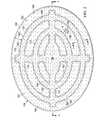
- FIG. 2is a schematic, plan view of an illustrative abdominal treatment device
- FIG. 3is a schematic, cross-sectional view of a portion of the illustrative abdominal treatment device of FIG. 2 taken along line 3 - 3 ;
- FIG. 4Ais a schematic plan view of a portion of an abdominal treatment device
- FIG. 4Bis a schematic cross section of a portion of the abdominal treatment device of FIG. 4A taken along line 4 B- 4 B;
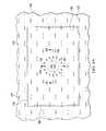
- FIG. 5is another schematic, plan view of another illustrative abdominal treatment device
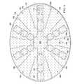
- FIG. 6is a schematic, plan view of another illustrative abdominal treatment device
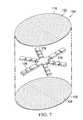
- FIG. 7is a schematic, exploded perspective view of another illustrative abdominal treatment device.
- FIG. 8is a schematic, plan view of the illustrative abdominal treatment device of FIG. 6 shown with an additional feature.
- the system 100includes an abdominal treatment device 104 .
- the system 100 and the abdominal treatment device 104are for treating a tissue site 106 of a patient.
- the tissue site 106may be the bodily tissue of any human, animal, or other organism.
- the tissue site 106includes tissue in a body cavity, and in particular the abdominal cavity 102 .
- the tissue site 106includes the abdominal contents 108 or tissue that is proximate the abdominal cavity 102 .
- Treatment of the tissue site 106may include removal of fluids, e.g., ascites, protection of the abdominal cavity, or reduced-pressure therapy.
- the abdominal treatment device 104is disposed within the abdominal cavity 102 of the patient to treat the tissue site 106 .
- the abdominal treatment device 104is supported by the abdominal contents 108 .
- the abdominal contents 108include a surface on which the abdominal treatment device 104 is positioned.
- a portion 110 of the abdominal treatment device 104may be positioned in or proximate to a first paracolic gutter 112 , and another portion 114 may be placed in or proximate to a second paracolic gutter 116 .
- the abdominal treatment device 104is formed with a plurality of liquid-impermeable layers 117 , e.g., a first liquid-impermeable layer 118 and a second liquid-impermeable layer 120 .
- FIG. 1is a schematic drawing and is not to scale.
- the plurality of liquid-impermeable layers 117e.g., layers 118 , 120 , is formed with fenestrations 122 , 124 , respectively.
- “Liquid impermeable” with respect to “liquid-impermeable layers”means that the layers are formed with a liquid-impermeable material.
- the layermay be liquid permeable when fenestrated, but nonetheless is referred to as a liquid-impermeable layer.
- the fenestrations 122 , 124may take any shape, e.g., circular apertures, rectangular openings, polygons, or any other shape.
- the fenestrations 122 , 124are presented in this illustrative embodiment as slits, or linear cuts.
- a foam spacer 125is disposed between at least two layers of the plurality of liquid-impermeable layers, e.g., the first liquid-impermeable layer 118 and the second liquid-impermeable layer 120 . In considering FIG.
- the abdominal treatment device 104has a first side 105 and a second, tissue-facing side 107 .
- the abdominal treatment device 104is typically symmetrical such that the sides 105 , 107 are same. Reference to different sides of the abdominal treatment device 104 is made for explanation purposes.
- a manifold 126or manifold pad, distributes reduced pressure to the abdominal treatment device 104 .
- a sealing member 128provides a fluid seal over the abdominal cavity 102 .
- One or more skin closure devicesmay be placed on a patient's epidermis 130 .
- a reduced-pressure connector subsystem 132may be used to fluidly connect the abdominal treatment device 104 to a reduced-pressure conduit 134 .
- the reduced-pressure connector subsystem 132may include a reduced-pressure connector 136 , or interface, and the manifold 126 .
- the reduced-pressure connector subsystem 132may be an in situ connector (not shown) on the abdominal treatment device 104 or any other device for supplying reduced pressure to the abdominal treatment device 104 .
- the reduced-pressure conduit 134is fluidly coupled to a reduced-pressure source 138 .
- reduced pressureis delivered to the abdominal treatment device 104 through the manifold 126 which receives reduced pressure through the reduced-pressure connector 136 , which is coupled to the reduced-pressure delivery conduit 134 .
- the reduced-pressure source 138delivers reduced pressure to the reduced-pressure delivery conduit 134 .
- the reduced pressuremay be applied to the tissue site 106 to help promote removal of ascites, exudates, or other fluids from the tissue site 106 .
- reduced pressuremay be applied to stimulate the growth of additional tissue.
- only fluid removalmay be desired.
- reduced pressuregenerally refers to a pressure less than the ambient pressure at a tissue site that is being subjected to treatment. In most cases, this reduced pressure will be less than the atmospheric pressure at which the patient is located. Alternatively, the reduced pressure may be less than a hydrostatic pressure at the tissue site. Reduced pressure may initially generate fluid flow in the manifold 126 , the reduced-pressure delivery conduit 134 , and proximate the tissue site 106 .
- the manifold 126is shown adjacent to the abdominal treatment device 104 .
- the manifold 126may take many forms.
- the term “manifold” as used hereingenerally refers to a substance or structure that is provided to assist in applying reduced pressure to, delivering fluids to, or removing fluids from the tissue site 106 or other location.
- the manifold 126typically includes a plurality of flow channels or pathways that distribute the fluids provided to and removed around the manifold 126 . In one illustrative embodiment, the flow channels or pathways are interconnected to improve distribution of fluids provided or removed from the tissue site 106 .
- the manifold 126may be a biocompatible material that is capable of being placed in contact with tissue site.
- manifold 126may include, without limitation, devices that have structural elements arranged to form flow channels, cellular foam, such as open-cell foam, porous tissue collections, liquids, gels and foams that include or cure to include flow channels.
- the manifold 126may be porous and may be made from foam, gauze, felted mat, or any other material suited to a particular biological application.
- the manifold 126is a porous foam and includes a plurality of interconnected cells or pores that act as flow channels.
- the porous foammay be a polyurethane, open-cell, reticulated foam, such as a GranuFoam® material manufactured by Kinetic Concepts, Incorporated of San Antonio, Tex. Other embodiments might include “closed cells.”
- the manifold 126may also be used to distribute fluids, such as medications, antibacterials, growth factors, and various solutions to the tissue site 106 or to another location.
- Other layersmay be included in or on the manifold 126 , such as absorptive materials, wicking materials, hydrophobic materials, and hydrophilic materials.
- the foam spacer 125 in the abdominal treatment device 104may be made from any of the same materials as the manifold 126 .
- the foam spacer 125may be a polyurethane, open-cell, reticulated foam, such as a GranuFoam® material.
- the sealing member 128is placed over the abdominal cavity 102 and provides a fluid seal.
- fluid sealor “seal,” means a seal adequate to maintain reduced pressure at a desired site given the particular reduced-pressure source 138 or subsystem involved.
- the sealing member 128may be a cover that is used to secure the manifold 126 on a portion of the abdominal treatment device 104 .
- the sealing member 128may be impermeable or semi-permeable.
- the sealing member 128is capable of maintaining reduced pressure at the tissue site 106 after installation of the sealing member 128 over the abdominal cavity 102 and particularly an abdominal cavity opening 140 .
- the sealing member 128may be a flexible over-drape or film formed from a silicone-based compound, acrylic, hydrogel or hydrogel-forming material, or any other biocompatible material that includes the impermeability or permeability characteristics as desired for applying reduced pressure to the tissue site 106 .
- the sealing member 128may further include an attachment device 142 to secure the sealing member 128 to the patient's epidermis 130 .
- the attachment device 142may take many forms.
- the attachment devicemay be an adhesive layer 144 that may be positioned along a perimeter, the entirety of, or any portion of the sealing member 128 to provide, directly or indirectly, the fluid seal with the patient's epidermis 130 .
- the adhesive layer 144may also be pre-applied to the sealing member 128 and covered with a releasable backing, or member (not shown), that is removed at the time of application.
- the reduced-pressure connector 136may be, as one example, a port or connector, which permits the passage of fluid from the manifold 126 to the reduced-pressure delivery conduit 134 and vice versa. For example, fluid collected from the tissue site 106 using the manifold 126 and the abdominal treatment device 104 may enter the reduced-pressure delivery conduit 134 via the reduced-pressure connector 136 . In another embodiment, the system 100 may omit the reduced-pressure connector 136 and the reduced-pressure delivery conduit 134 may be inserted directly into the sealing member 128 and into the manifold 126 .
- the reduced-pressure delivery conduit 134may be a medical conduit or tubing or any other device for transporting a reduced pressure and fluid.
- the reduced-pressure delivery conduit 134may be a multi-lumen member. In one embodiment, the reduced-pressure delivery conduit 134 is a two-lumen conduit with one lumen for reduced pressure and liquid transport and one lumen for communicating pressure to a pressure sensor.
- Reduced pressureis supplied to the reduced-pressure delivery conduit 134 by the reduced-pressure source 138 .
- a wide range of reduced pressuresmay be supplied by the reduced-pressure source 138 .
- the pressuremay be in the range ⁇ 50 to ⁇ 300 mm Hg and in another embodiment, in the range of ⁇ 100 mm Hg to ⁇ 200 mm Hg.
- the pressuremay be, for example, ⁇ 100, ⁇ 110, ⁇ 120, ⁇ 125, ⁇ 130, ⁇ 140, ⁇ 150, ⁇ 160, ⁇ 170, ⁇ 180, ⁇ 190, or ⁇ 200 mm Hg.
- the reduced-pressure source 138includes preset selectors for ⁇ 100 mm Hg, ⁇ 125 mm Hg, and ⁇ 150 mm Hg.
- the reduced-pressure source 138may also include a number of alarms, such as a blockage alarm, a leakage alarm, or a battery-low alarm.
- the reduced-pressure source 138could be a portable source, wall source, or other unit for abdominal cavities.
- the reduced-pressure source 138may selectively deliver a constant pressure, varied pressure (patterned or random), intermittent pressure, or continuous pressure.
- the fluid removed from the cavity through the reduced-pressure delivery conduit 134could be as much as 5 L or more per day depending on the circumstances.
- a canister or fluid reservoir for receiving removed fluidsmay be associated with the reduced-pressure source 138 .
- a number of different devicesmay be added to a portion of the reduced-pressure delivery conduit 134 .
- the device 146may be a fluid reservoir, or canister collection member, a pressure-feedback device, a volume detection system, a blood detection system, an infection detection system, a filter, a flow monitoring system, a temperature monitoring system, or other device. Multiple devices 146 may be included. Some of these devices, e.g., the fluid collection member, may be formed integrally with the reduced-pressure source 138 .
- the abdominal treatment device 104is flexible and easily positioned within the abdominal cavity. At the same time, the abdominal treatment device 104 is adapted to avoid blockage at discrete locations on the abdominal treatment device 104 by having fluid flow over a large range of directions. In order to facilitate flexibility, the abdominal treatment device 104 may be formed with the foam spacer 125 smaller than the liquid-impermeable layers 117 .
- the abdominal treatment device 104includes the plurality of liquid-impermeable layers 117 , e.g., the first liquid-impermeable layer 118 and the second liquid-impermeable layer 120 .
- the micro-channel 168 spaceis formed between adjacent layers of the plurality of liquid-impermeable layers 117 . Additional layers may be included in the plurality of liquid-impermeable layers 117 .
- the plurality of liquid-impermeable layers 117is formed with fenestrations, e.g., fenestrations 122 , 124 , and the layers of the plurality of liquid-impermeable layers 117 are placed proximate to one another to form a substantially flat member having a co-extensive area A 1 .
- the coextensive area A 1is the plan view area (before insertion) of where the layers of the plurality of liquid-impermeable layers 117 that are adjacent to the foam spacer 125 are co-extensive with one another.
- the foam spacer 125is disposed between at least two layers of the plurality of liquid-impermeable layers 117 .
- the plurality of liquid-impermeable layers 117may be formed from the same materials as the sealing member 128 .
- each of the liquid-impermeable layers 117may be of a thickness in the range of 50 to 120 microns and in another non-limiting embodiment may be approximately 80 microns.
- the foam spacer 125has a plan-view area A 2 , e.g., the area shown in plan view, that is less than the coextensive area A 1 of the plurality of liquid-impermeable layers 117 .
- the plan-view area A 2is less than the coextensive area A 2 of the plurality of liquid-impermeable layers 117 at least in part to enhance flexibility.
- the plan-view area A 2is less than 80 percent (80%) of the coextensive area A 1 of the plurality of liquid-impermeable layers 117 , i.e. A 2 ⁇ 0.8A 1 .
- the plan-view area A 2may be less of a percentage of A 1 , e.g., A 2 ⁇ 0.7A 1 , A 2 ⁇ 0.6A 1 , A 2 ⁇ 0.5A 1 , A 2 ⁇ 0.4A 1 , A 2 ⁇ 0.3A 1 , A 2 ⁇ 0.2A 1 , A 2 ⁇ 0.1A 1 , etc.
- a plurality of bonds 160may be used to couple at least two layers of the plurality of liquid-impermeable layers 117 . Any pattern or random bonds may be used for the plurality of bonds 160 .
- the bondsmay be formed using any known technique, including without limitation, welding (e.g., ultrasonic or RF welding), bonding, adhesives, cements, or other bonding technique or apparatus.
- the plurality of bonds 160may include spacer bonds 162 that may be around or surround edges 164 of the foam spacer 125 as shown in plan view.
- the spacer bonds 162may be a stitch bond as shown in FIG. 2 or a solid bond as shown in FIG. 5 .
- the spacer bonds 162help secure the foam spacer 125 in a fixed position relative to the plurality of liquid-impermeable layers 117 .
- the fenestrationsallow fluids to enter the space between the plurality of liquid-impermeable layers 117 .
- the fluids that enter the fenestrations 122 , 124move directly or indirectly towards a reduced-pressure source.
- a reduced pressuremay be, and typically is, applied to a center portion 166 of the abdominal treatment device 104 or elsewhere to cause fluid flow through the fenestrations 122 , 124 and within the foam spacer 125 or micro-channels 168 ( FIG. 3 ) formed between adjacent layers of the plurality of liquid-impermeable layers 117 .
- the foam spacer 125communicates reduced pressure within the plurality of liquid-impermeable layers 117 and often will be a dominant source of reduced-pressure.
- the reduced pressure at various locationsmay be represented by pressure vectors, e.g., reduced-pressure vectors 156 ( FIG. 2 ).
- the present embodiment of the abdominal treatment device 104delivers reduced pressure over a large angle, e.g., 270-360 degrees, for a given point. Typically, reduced pressure is experienced in all directions (360 degrees).
- the foam spacer 125provides the strongest source of reduced pressure within the micro-channels 168 and influences the flow directions.
- a cylindrical analytical control volume 158which is a control volume for analyzing pressure at a location in the micro-channel 168 .
- the control volume 158experiences reduced pressure over 360 degrees.
- the abdominal treatment device 104may have all the analytical control volumes, e.g., analytical control volume 158 , within a treatment area, or target fluid removal zone, experiencing 360 degrees of reduced pressure. Thus, if a blockage occurs in one direction for a analytical control volume, fluid may continue to move in other directions.
- the angle over which the reduced pressure acts on a given analytical control volume, e.g., analytical control volume 158is defined as angle theta ( ⁇ ).
- the area of the abdominal treatment device 104 that experiences greater than 270 degrees of reduced pressuremay be defined as a target fluid removal zone.
- the areamay experience 270, 280, 290, 300, 310, 320, 330, 340, 350, or 360 degrees of reduced pressure.
- the target fluid removal zoneis generally defined as the area bound substantially by an outer peripheral edge of the foam spacer 125 making allowances for any discontinuities.
- the target fluid removal zoneexists on the portion of the abdominal treatment device 104 that is inboard from a peripheral edge 150 by a distance 152 .
- the target fluid removal zoneis from a peripheral edge 167 of the foam spacer 125 (or from the outer edge of a concentric circle 154 ) and inward.
- the target fluid removal zonemay have portions in which the analytical control volumes would have an angle theta ( ⁇ ) less than 360 degrees, e.g., 270 degrees, but preferably the majority, i.e., >50%, of locations analyzed will have 360 degrees of reduced pressure acting upon them.
- the target flow zonemay be defined as having more than 70 percent (70%) of the locations experiencing reduced pressure in 360 degrees.
- the foam spacer 125may be formed with a plurality of windows or window openings, such as where cylindrical analytical control volume 158 is shown.
- FIGS. 4A and 4Ba portion of an abdominal treatment device 104 is presented.
- the portionshows portions of a foam spacer 125 under a first liquid-impermeable layer 118 having fenestrations 127 .
- the first liquid-impermeable layer 118is bonded with bonds 160 to a second liquid-impermeable layer 120 with the foam spacer 125 therebetween.
- a window 129is formed by the foam spacer 125 in this portion of target fluid removal zone. Because the foam spacer 125 of the window 129 provides the main delivery of reduced pressure, an analytical control volume 158 experiences reduced pressure vectors 158 over angle theta of 360 degrees.
- the reduced pressure in a given directionwill be related to the distance from the analytical control volume 158 to the foam spacer 125 in a given direction.
- a first reduced-pressure vector 159 and a second reduced-pressure vector 161are the greatest because they are at locations closest to the foam spacer 125 .
- Third and fourth reduced-pressure vectors 163 and 165are the least because they are the farthest from the foam spacer 125 in a given direction.
- the foam spacer 125may take numerous possible shapes.
- the shape and size of the foam spacer 125are typically selected to promote flexibility of the abdominal treatment device 104 , i.e., to make the abdominal treatment device 104 compliant.
- the flexibilitytypically helps place the abdominal treatment device 104 or a portion of the abdominal treatment device 104 in difficult-to-reach locations, such as the paracolic gutters 112 and 116 , and helps remove the abdominal treatment device 104 in certain situations.
- the abdominal treatment device 104may be applied in some situations through an open abdomen with a directly connecting reduced-pressure delivery conduit 134 , the abdominal cavity opening 140 closed, and then later the abdominal treatment device 104 may be removed through a surgical incision, e.g., an incision in the range of 5 centimeters to 40 centimeters—or any sub-range thereof.
- the shape of the foam spacer 125may be selected to promote a range of reduced-pressure vectors 156 in a target flow zone or to direct flow.
- the foam spacer 125is formed as a plurality of arced members, e.g., concentric circles or elliptical members, 170 that are interconnected by members 172 .
- the target treatment zonemay experience 360 degrees of reduced pressure.
- FIG. 5presents another illustrative shape.
- the foam spacer 125 of the abdominal treatment device 104includes mirrored c-shaped members that are interconnected.
- the foam spacer 125is formed with spacer bonds 162 that are one or more solid bonds.
- analytical control volumessuch as analytical control volume 158
- in the target flow zoneexperience reduced-pressure vectors 156 that may be less than 360 degrees but greater than 270 degrees.
- Other pointse.g., interior point 174 , may experience 360 degrees of reduced-pressure vectors 156 .
- the target flow zone for this embodimentis inboard of the outer peripheral edge 167 of the foam spacer 125 .
- the target flow zonemay be defined as having more than 70 percent (70%) of the locations experiencing reduced pressure in 360 degrees.
- FIG. 6presents a foam spacer 125 formed as a plurality of interconnected, annular circles.
- analytical control volumese.g., first analytical control volume 158 and second analytical control volumes 174
- the spacer bonds 162are shown as a stitch bond in this example.
- FIGS. 7 and 8another illustrative embodiment of an abdominal treatment device 104 is presented, but in this embodiment, control of the direction of the reduced pressure is desired.
- the foam spacer 125is formed as a star with a plurality of spaced leg members 178 . Longitudinal bonds 182 have been added to direct fluid flow in a particular direction. Fluids attracted by this embodiment of the abdominal treatment device 104 primarily have flow along the foam spacer 125 and along flow channels 184 formed by the longitudinal bonds 182 .
- the foam spacer 125is disposed between the first liquid-impermeable layer 118 and second liquid-impermeable layer 120 of the plurality of liquid-impermeable layers 117 .
- a plurality of bonds 160including spacer bonds 162 , are formed.
- the spacer bonds 162 around the peripherymay be excluded to leave an open intake space between the layers 118 , 120 at the periphery.
- the flow channels 180are formed by placing the first longitudinal bonds 182 and the second longitudinal bonds 182 at desired locations.
- the longitudinal bonds 182 and 184may be formed radially outward from the center portion 166 .
- the longitudinal bonds 182 , 184may begin outboard of the center portion 166 as shown or may go all the way to the center portion 166 .
- Flow channels 180may be used where increased or directed reduced pressure is more important than guarding against blockage.
- Analytical control volume 186shows the reduced pressure vectors may be oriented mainly toward the center portion 166 .
- the abdominal cavity 102is opened and the abdominal treatment device 104 is deployed within the abdominal cavity 102 .
- the reduced pressure connector subsystem 132may be fluidly coupled to the abdominal treatment device 104 .
- the reduced pressure connector subsystem 132may be fluidly coupled to the reduced-pressure source 138 and the reduced-pressure source 138 activated.
- the abdominal treatment device 104may be removed through the open abdomen or later through a surgical incision.
- the abdominal treatment device 104may be manufactured, according to one illustrative embodiment, by providing the plurality of liquid-impermeable layers 117 that are fenestrated; stacking the plurality of liquid-impermeable layers 117 ; and disposing a foam spacer 125 between at least two layers of the plurality of liquid-impermeable layers 117 .
- the plurality of liquid-impermeable layers 117has a coextensive area A 1 .
- the foam spacer 125 disposed between at least two layers of the plurality of liquid-impermeable layers 117has a plan-view area A 2 .
- a 2is less than 80% of A 1 (i.e., A 2 ⁇ 0.8A 1 ).
- the foam spacer 125is configured and positioned such that, under reduced pressure, a target fluid removal zone experiences reduced-pressure vectors over an angle theta ( ⁇ ) that is greater than 90 degrees.
Landscapes
- Health & Medical Sciences (AREA)
- Heart & Thoracic Surgery (AREA)
- General Health & Medical Sciences (AREA)
- Engineering & Computer Science (AREA)
- Biomedical Technology (AREA)
- Life Sciences & Earth Sciences (AREA)
- Animal Behavior & Ethology (AREA)
- Vascular Medicine (AREA)
- Public Health (AREA)
- Veterinary Medicine (AREA)
- Anesthesiology (AREA)
- Hematology (AREA)
- Media Introduction/Drainage Providing Device (AREA)
Abstract
Description
Claims (14)
Priority Applications (19)
| Application Number | Priority Date | Filing Date | Title |
|---|---|---|---|
| US13/043,987US8469935B2 (en) | 2010-03-11 | 2011-03-09 | Abdominal treatment systems, delivery devices, and methods |
| CA2789002ACA2789002C (en) | 2010-03-11 | 2011-03-10 | Abdominal treatment systems, delivery devices, and methods |
| EP11710939.7AEP2544730B2 (en) | 2010-03-11 | 2011-03-10 | Abdominal treatment systems, delivery devices, and methods |
| JP2012557235AJP5844751B2 (en) | 2010-03-11 | 2011-03-10 | Abdominal treatment system, delivery device, and method |
| PCT/US2011/027835WO2011112774A1 (en) | 2010-03-11 | 2011-03-10 | Abdominal treatment systems, delivery devices, and methods |
| AU2011224324AAU2011224324B2 (en) | 2010-03-11 | 2011-03-10 | Abdominal treatment systems, delivery devices, and methods |
| CN201510811131.2ACN105287104B (en) | 2010-03-11 | 2011-03-10 | Device for treating the abdominal cavity |
| EP20167306.8AEP3695858A1 (en) | 2010-03-11 | 2011-03-10 | Abdominal treatment systems, delivery devices, and methods |
| CN201180011563.5ACN102811750B (en) | 2010-03-11 | 2011-03-10 | Intraperitoneal therapy systems, delivery devices, and methods |
| CA3015738ACA3015738C (en) | 2010-03-11 | 2011-03-10 | Abdominal treatment systems, delivery devices, and methods |
| EP16157204.5AEP3042671B1 (en) | 2010-03-11 | 2011-03-10 | Abdominal treatment systems, delivery devices, and methods |
| TW100108404ATW201200175A (en) | 2010-03-11 | 2011-03-11 | Abdominal treatment systems, delivery devices, and methods |
| US13/903,818US9259356B2 (en) | 2010-03-11 | 2013-05-28 | Abdominal treatment systems, delivery devices, and methods |
| JP2015227047AJP6294287B2 (en) | 2010-03-11 | 2015-11-19 | Abdominal treatment system, delivery device, and method |
| US14/989,533US10744240B2 (en) | 2010-03-11 | 2016-01-06 | Abdominal treatment systems, delivery devices, and methods |
| AU2016201800AAU2016201800B2 (en) | 2010-03-11 | 2016-03-22 | Abdominal treatment systems, delivery devices, and methods |
| JP2018024620AJP6707099B2 (en) | 2010-03-11 | 2018-02-15 | Abdominal treatment system, delivery device, and method |
| JP2020036899AJP2020096965A (en) | 2010-03-11 | 2020-03-04 | Abdominal treatment system, delivery device, and method |
| US16/924,657US20200338246A1 (en) | 2010-03-11 | 2020-07-09 | Abdominal treatment systems, delivery devices, and methods |
Applications Claiming Priority (2)
| Application Number | Priority Date | Filing Date | Title |
|---|---|---|---|
| US31299010P | 2010-03-11 | 2010-03-11 | |
| US13/043,987US8469935B2 (en) | 2010-03-11 | 2011-03-09 | Abdominal treatment systems, delivery devices, and methods |
Related Child Applications (1)
| Application Number | Title | Priority Date | Filing Date |
|---|---|---|---|
| US13/903,818DivisionUS9259356B2 (en) | 2010-03-11 | 2013-05-28 | Abdominal treatment systems, delivery devices, and methods |
Publications (2)
| Publication Number | Publication Date |
|---|---|
| US20110224630A1 US20110224630A1 (en) | 2011-09-15 |
| US8469935B2true US8469935B2 (en) | 2013-06-25 |
Family
ID=44560640
Family Applications (4)
| Application Number | Title | Priority Date | Filing Date |
|---|---|---|---|
| US13/043,987Expired - Fee RelatedUS8469935B2 (en) | 2010-03-11 | 2011-03-09 | Abdominal treatment systems, delivery devices, and methods |
| US13/903,818Expired - Fee RelatedUS9259356B2 (en) | 2010-03-11 | 2013-05-28 | Abdominal treatment systems, delivery devices, and methods |
| US14/989,533Expired - Fee RelatedUS10744240B2 (en) | 2010-03-11 | 2016-01-06 | Abdominal treatment systems, delivery devices, and methods |
| US16/924,657AbandonedUS20200338246A1 (en) | 2010-03-11 | 2020-07-09 | Abdominal treatment systems, delivery devices, and methods |
Family Applications After (3)
| Application Number | Title | Priority Date | Filing Date |
|---|---|---|---|
| US13/903,818Expired - Fee RelatedUS9259356B2 (en) | 2010-03-11 | 2013-05-28 | Abdominal treatment systems, delivery devices, and methods |
| US14/989,533Expired - Fee RelatedUS10744240B2 (en) | 2010-03-11 | 2016-01-06 | Abdominal treatment systems, delivery devices, and methods |
| US16/924,657AbandonedUS20200338246A1 (en) | 2010-03-11 | 2020-07-09 | Abdominal treatment systems, delivery devices, and methods |
Country Status (8)
| Country | Link |
|---|---|
| US (4) | US8469935B2 (en) |
| EP (3) | EP3695858A1 (en) |
| JP (4) | JP5844751B2 (en) |
| CN (2) | CN105287104B (en) |
| AU (2) | AU2011224324B2 (en) |
| CA (2) | CA3015738C (en) |
| TW (1) | TW201200175A (en) |
| WO (1) | WO2011112774A1 (en) |
Cited By (4)
| Publication number | Priority date | Publication date | Assignee | Title |
|---|---|---|---|---|
| US20140228787A1 (en)* | 2013-02-13 | 2014-08-14 | Paul Hartmann Ag | Abdominal wound dressing comprising joining means |
| US9509818B2 (en)* | 2013-09-17 | 2016-11-29 | Empire Technology Development Llc | Automatic contacts sorting |
| US11135351B2 (en)* | 2016-08-30 | 2021-10-05 | Smith & Nephew Plc | Systems and methods for applying reduced pressure therapy |
| US20210346589A1 (en)* | 2018-10-15 | 2021-11-11 | Kci Licensing, Inc. | Micro balloon-on-tube wound filler |
Families Citing this family (40)
| Publication number | Priority date | Publication date | Assignee | Title |
|---|---|---|---|---|
| GB0808376D0 (en) | 2008-05-08 | 2008-06-18 | Bristol Myers Squibb Co | Wound dressing |
| GB0817796D0 (en) | 2008-09-29 | 2008-11-05 | Convatec Inc | wound dressing |
| US8469935B2 (en) | 2010-03-11 | 2013-06-25 | Kci Licensing, Inc. | Abdominal treatment systems, delivery devices, and methods |
| GB201020236D0 (en) | 2010-11-30 | 2011-01-12 | Convatec Technologies Inc | A composition for detecting biofilms on viable tissues |
| WO2012078724A1 (en) | 2010-12-08 | 2012-06-14 | Convatec Technologies Inc. | Apparatus and method for applying pressure to a wound site |
| US10207031B2 (en) | 2010-12-08 | 2019-02-19 | Convatec Technologies Inc. | Integrated system for assessing wound exudates |
| ES2748519T3 (en) | 2010-12-08 | 2020-03-17 | Convatec Technologies Inc | Wound exudate system accessory |
| WO2013066426A2 (en) | 2011-06-24 | 2013-05-10 | Kci Licensing, Inc. | Reduced-pressure dressings employing tissue-fixation elements |
| GB201115182D0 (en) | 2011-09-02 | 2011-10-19 | Trio Healthcare Ltd | Skin contact material |
| GB2497406A (en) | 2011-11-29 | 2013-06-12 | Webtec Converting Llc | Dressing with a perforated binder layer |
| GB201120693D0 (en) | 2011-12-01 | 2012-01-11 | Convatec Technologies Inc | Wound dressing for use in vacuum therapy |
| JP2016507663A (en) | 2012-12-20 | 2016-03-10 | コンバテック・テクノロジーズ・インコーポレイテッドConvatec Technologies Inc | Processing of chemically modified cellulosic fibers |
| AU2014207832B2 (en)* | 2013-01-16 | 2018-03-15 | Kci Licensing, Inc. | Dressing with asymmetric absorbent core for negative pressure wound therapy |
| CN105073077A (en) | 2013-02-12 | 2015-11-18 | 电化学氧概念公司 | Dressing for wound treatment |
| DE102013002497A1 (en)* | 2013-02-13 | 2014-08-14 | Paul Hartmann Ag | Bandage kit for the treatment of wound cavities |
| WO2016015001A2 (en)* | 2014-07-24 | 2016-01-28 | Kci Licensing, Inc. | Combination fluid instillation and negative pressure dressing |
| GB2543544A (en) | 2015-10-21 | 2017-04-26 | Brightwake Ltd | Wound dressing |
| AU2017243601A1 (en) | 2016-03-30 | 2018-11-22 | Acib Gmbh | Detecting microbial infection in wounds |
| PL3435941T3 (en) | 2016-03-30 | 2022-05-09 | Convatec Technologies Inc. | Detecting microbial infections in wounds |
| US10625001B2 (en)* | 2016-05-02 | 2020-04-21 | Rex McDonald | Chest seal and vacuum system |
| MX2019000232A (en) | 2016-07-08 | 2019-11-12 | Convatec Technologies Inc | Fluid flow sensing. |
| EP3481348A4 (en) | 2016-07-08 | 2020-02-26 | ConvaTec Technologies Inc. | Fluid collection apparatus |
| DK3481349T3 (en) | 2016-07-08 | 2021-07-12 | Convatec Technologies Inc | Flexible vacuum system |
| WO2018140386A2 (en)* | 2017-01-27 | 2018-08-02 | Kci Licensing, Inc. | Multi-layer abdominal closure dressing with instillation capabilities |
| US11285048B2 (en) | 2017-08-02 | 2022-03-29 | Kci Licensing, Inc. | Multi-layer compartment dressing and negative-pressure treatment method |
| US20210236342A1 (en)* | 2017-10-24 | 2021-08-05 | Kci Licensing, Inc. | Wound Dressings and Systems with Low-Flow Therapeutic Gas Sources for Topical Wound Therapy and Related Methods |
| CN111836655A (en) | 2017-11-16 | 2020-10-27 | 康沃特克有限公司 | fluid collection equipment |
| US12246125B2 (en)* | 2018-07-12 | 2025-03-11 | Solventum Intellectual Properties Company | Abdominal dressing with user selection of fascial closure force profile |
| US10973601B2 (en)* | 2018-11-16 | 2021-04-13 | WEG Surgical Solutions, LLC | Sterile drape without air-trapping wrinkles for use in warming system |
| US12290332B2 (en) | 2018-11-16 | 2025-05-06 | WEG Surgical Solutions, LLC | Air gap detectors in heating system for draped basin |
| EP3917476A1 (en)* | 2019-02-01 | 2021-12-08 | KCI Licensing, Inc. | Abdominal negative pressure therapy dressing with remote wound sensing capability |
| EP3969071A1 (en)* | 2019-05-13 | 2022-03-23 | KCI Licensing, Inc. | Dressing including outlet connection fluid buffer |
| EP4295869A3 (en) | 2019-06-03 | 2024-03-20 | Convatec Limited | Methods and devices to disrupt and contain pathogens |
| WO2020256837A1 (en)* | 2019-06-17 | 2020-12-24 | Kci Licensing, Inc. | Abdominal negative-pressure therapy dressing with closed-loop force management control |
| EP4007552B1 (en)* | 2019-08-01 | 2025-03-19 | Solventum Intellectual Properties Company | Hand dressing for use with negative pressure wound therapy |
| US20220355021A1 (en)* | 2019-09-05 | 2022-11-10 | Kci Licensing, Inc. | Long-Term Wear Tissue Interfaces For High-Closure Force Negative- Pressure Therapy Dressings |
| WO2021111370A1 (en)* | 2019-12-04 | 2021-06-10 | Kci Licensing, Inc. | Dressing with spacer fabric to promote medial tension |
| US11331221B2 (en) | 2019-12-27 | 2022-05-17 | Convatec Limited | Negative pressure wound dressing |
| US11771819B2 (en) | 2019-12-27 | 2023-10-03 | Convatec Limited | Low profile filter devices suitable for use in negative pressure wound therapy systems |
| WO2025051634A1 (en)* | 2023-09-05 | 2025-03-13 | T.J.Smith And Nephew, Limited | Wound treatment systems, devices, and methods |
Citations (122)
| Publication number | Priority date | Publication date | Assignee | Title |
|---|---|---|---|---|
| US1355846A (en) | 1920-02-06 | 1920-10-19 | David A Rannells | Medical appliance |
| US2547758A (en) | 1949-01-05 | 1951-04-03 | Wilmer B Keeling | Instrument for treating the male urethra |
| US2632443A (en) | 1949-04-18 | 1953-03-24 | Eleanor P Lesher | Surgical dressing |
| GB692578A (en) | 1949-09-13 | 1953-06-10 | Minnesota Mining & Mfg | Improvements in or relating to drape sheets for surgical use |
| US2682873A (en) | 1952-07-30 | 1954-07-06 | Johnson & Johnson | General purpose protective dressing |
| US2910763A (en) | 1955-08-17 | 1959-11-03 | Du Pont | Felt-like products |
| US2969057A (en) | 1957-11-04 | 1961-01-24 | Brady Co W H | Nematodic swab |
| US3066672A (en) | 1960-09-27 | 1962-12-04 | Jr William H Crosby | Method and apparatus for serial sampling of intestinal juice |
| US3367332A (en) | 1965-08-27 | 1968-02-06 | Gen Electric | Product and process for establishing a sterile area of skin |
| US3520300A (en) | 1967-03-15 | 1970-07-14 | Amp Inc | Surgical sponge and suction device |
| US3568675A (en) | 1968-08-30 | 1971-03-09 | Clyde B Harvey | Fistula and penetrating wound dressing |
| US3648692A (en) | 1970-12-07 | 1972-03-14 | Parke Davis & Co | Medical-surgical dressing for burns and the like |
| US3682180A (en) | 1970-06-08 | 1972-08-08 | Coilform Co Inc | Drain clip for surgical drain |
| US3826254A (en) | 1973-02-26 | 1974-07-30 | Verco Ind | Needle or catheter retaining appliance |
| DE2640413A1 (en) | 1976-09-08 | 1978-03-09 | Wolf Gmbh Richard | CATHETER MONITORING DEVICE |
| US4080970A (en) | 1976-11-17 | 1978-03-28 | Miller Thomas J | Post-operative combination dressing and internal drain tube with external shield and tube connector |
| US4096853A (en) | 1975-06-21 | 1978-06-27 | Hoechst Aktiengesellschaft | Device for the introduction of contrast medium into an anus praeter |
| US4139004A (en) | 1977-02-17 | 1979-02-13 | Gonzalez Jr Harry | Bandage apparatus for treating burns |
| US4165748A (en) | 1977-11-07 | 1979-08-28 | Johnson Melissa C | Catheter tube holder |
| US4184510A (en) | 1977-03-15 | 1980-01-22 | Fibra-Sonics, Inc. | Valued device for controlling vacuum in surgery |
| US4233969A (en) | 1976-11-11 | 1980-11-18 | Lock Peter M | Wound dressing materials |
| US4245630A (en) | 1976-10-08 | 1981-01-20 | T. J. Smith & Nephew, Ltd. | Tearable composite strip of materials |
| US4256109A (en) | 1978-07-10 | 1981-03-17 | Nichols Robert L | Shut off valve for medical suction apparatus |
| US4261363A (en) | 1979-11-09 | 1981-04-14 | C. R. Bard, Inc. | Retention clips for body fluid drains |
| US4275721A (en) | 1978-11-28 | 1981-06-30 | Landstingens Inkopscentral Lic, Ekonomisk Forening | Vein catheter bandage |
| US4284079A (en) | 1979-06-28 | 1981-08-18 | Adair Edwin Lloyd | Method for applying a male incontinence device |
| US4297995A (en) | 1980-06-03 | 1981-11-03 | Key Pharmaceuticals, Inc. | Bandage containing attachment post |
| US4333468A (en) | 1980-08-18 | 1982-06-08 | Geist Robert W | Mesentery tube holder apparatus |
| US4373519A (en) | 1981-06-26 | 1983-02-15 | Minnesota Mining And Manufacturing Company | Composite wound dressing |
| US4382441A (en) | 1978-12-06 | 1983-05-10 | Svedman Paul | Device for treating tissues, for example skin |
| US4392853A (en) | 1981-03-16 | 1983-07-12 | Rudolph Muto | Sterile assembly for protecting and fastening an indwelling device |
| US4392858A (en) | 1981-07-16 | 1983-07-12 | Sherwood Medical Company | Wound drainage device |
| US4419097A (en) | 1981-07-31 | 1983-12-06 | Rexar Industries, Inc. | Attachment for catheter tube |
| EP0100148A1 (en) | 1982-07-06 | 1984-02-08 | Dow Corning Limited | Medical-surgical dressing and a process for the production thereof |
| US4465485A (en) | 1981-03-06 | 1984-08-14 | Becton, Dickinson And Company | Suction canister with unitary shut-off valve and filter features |
| EP0117632A2 (en) | 1983-01-27 | 1984-09-05 | Johnson & Johnson Products Inc. | Adhesive film dressing |
| US4475909A (en) | 1982-05-06 | 1984-10-09 | Eisenberg Melvin I | Male urinary device and method for applying the device |
| US4480638A (en) | 1980-03-11 | 1984-11-06 | Eduard Schmid | Cushion for holding an element of grafted skin |
| US4525166A (en) | 1981-11-21 | 1985-06-25 | Intermedicat Gmbh | Rolled flexible medical suction drainage device |
| US4525374A (en) | 1984-02-27 | 1985-06-25 | Manresa, Inc. | Treating hydrophobic filters to render them hydrophilic |
| US4540412A (en) | 1983-07-14 | 1985-09-10 | The Kendall Company | Device for moist heat therapy |
| US4543100A (en) | 1983-11-01 | 1985-09-24 | Brodsky Stuart A | Catheter and drain tube retainer |
| US4548202A (en) | 1983-06-20 | 1985-10-22 | Ethicon, Inc. | Mesh tissue fasteners |
| US4551139A (en) | 1982-02-08 | 1985-11-05 | Marion Laboratories, Inc. | Method and apparatus for burn wound treatment |
| EP0161865A2 (en) | 1984-05-03 | 1985-11-21 | Smith and Nephew Associated Companies p.l.c. | Adhesive wound dressing |
| US4569348A (en) | 1980-02-22 | 1986-02-11 | Velcro Usa Inc. | Catheter tube holder strap |
| US4605399A (en) | 1984-12-04 | 1986-08-12 | Complex, Inc. | Transdermal infusion device |
| US4608041A (en) | 1981-10-14 | 1986-08-26 | Frese Nielsen | Device for treatment of wounds in body tissue of patients by exposure to jets of gas |
| US4640688A (en) | 1985-08-23 | 1987-02-03 | Mentor Corporation | Urine collection catheter |
| US4655754A (en) | 1984-11-09 | 1987-04-07 | Stryker Corporation | Vacuum wound drainage system and lipids baffle therefor |
| US4664662A (en) | 1984-08-02 | 1987-05-12 | Smith And Nephew Associated Companies Plc | Wound dressing |
| US4710165A (en) | 1985-09-16 | 1987-12-01 | Mcneil Charles B | Wearable, variable rate suction/collection device |
| US4733659A (en) | 1986-01-17 | 1988-03-29 | Seton Company | Foam bandage |
| GB2195255A (en) | 1986-09-30 | 1988-04-07 | Vacutec Uk Limited | Method and apparatus for vacuum treatment of an epidermal surface |
| US4743232A (en) | 1986-10-06 | 1988-05-10 | The Clinipad Corporation | Package assembly for plastic film bandage |
| GB2197789A (en) | 1986-11-28 | 1988-06-02 | Smiths Industries Plc | Anti-foaming disinfectants used in surgical suction apparatus |
| US4758220A (en) | 1985-09-26 | 1988-07-19 | Alcon Laboratories, Inc. | Surgical cassette proximity sensing and latching apparatus |
| US4787888A (en) | 1987-06-01 | 1988-11-29 | University Of Connecticut | Disposable piezoelectric polymer bandage for percutaneous delivery of drugs and method for such percutaneous delivery (a) |
| US4826494A (en) | 1984-11-09 | 1989-05-02 | Stryker Corporation | Vacuum wound drainage system |
| US4838883A (en) | 1986-03-07 | 1989-06-13 | Nissho Corporation | Urine-collecting device |
| US4840187A (en) | 1986-09-11 | 1989-06-20 | Bard Limited | Sheath applicator |
| US4863449A (en) | 1987-07-06 | 1989-09-05 | Hollister Incorporated | Adhesive-lined elastic condom cathether |
| US4872450A (en) | 1984-08-17 | 1989-10-10 | Austad Eric D | Wound dressing and method of forming same |
| US4878901A (en) | 1986-10-10 | 1989-11-07 | Sachse Hans Ernst | Condom catheter, a urethral catheter for the prevention of ascending infections |
| GB2220357A (en) | 1988-05-28 | 1990-01-10 | Smiths Industries Plc | Medico-surgical containers |
| US4897081A (en) | 1984-05-25 | 1990-01-30 | Thermedics Inc. | Percutaneous access device |
| US4906240A (en) | 1988-02-01 | 1990-03-06 | Matrix Medica, Inc. | Adhesive-faced porous absorbent sheet and method of making same |
| US4906233A (en) | 1986-05-29 | 1990-03-06 | Terumo Kabushiki Kaisha | Method of securing a catheter body to a human skin surface |
| US4919654A (en) | 1988-08-03 | 1990-04-24 | Kalt Medical Corporation | IV clamp with membrane |
| CA2005436A1 (en) | 1988-12-13 | 1990-06-13 | Glenda G. Kalt | Transparent tracheostomy tube dressing |
| US4941882A (en) | 1987-03-14 | 1990-07-17 | Smith And Nephew Associated Companies, P.L.C. | Adhesive dressing for retaining a cannula on the skin |
| US4953565A (en) | 1986-11-26 | 1990-09-04 | Shunro Tachibana | Endermic application kits for external medicines |
| US4953544A (en)* | 1987-09-25 | 1990-09-04 | Minnesota Mining And Manufacturing Company | Use of sorbent sheet materials as evaporative coolants |
| US4969880A (en) | 1989-04-03 | 1990-11-13 | Zamierowski David S | Wound dressing and treatment method |
| US4985019A (en) | 1988-03-11 | 1991-01-15 | Michelson Gary K | X-ray marker |
| GB2235877A (en) | 1989-09-18 | 1991-03-20 | Antonio Talluri | Closed wound suction apparatus |
| US5037397A (en) | 1985-05-03 | 1991-08-06 | Medical Distributors, Inc. | Universal clamp |
| US5086170A (en) | 1989-01-16 | 1992-02-04 | Roussel Uclaf | Process for the preparation of azabicyclo compounds |
| US5092858A (en) | 1990-03-20 | 1992-03-03 | Becton, Dickinson And Company | Liquid gelling agent distributor device |
| US5100396A (en) | 1989-04-03 | 1992-03-31 | Zamierowski David S | Fluidic connection system and method |
| US5134994A (en) | 1990-02-12 | 1992-08-04 | Say Sam L | Field aspirator in a soft pack with externally mounted container |
| US5149331A (en) | 1991-05-03 | 1992-09-22 | Ariel Ferdman | Method and device for wound closure |
| US5167613A (en) | 1992-03-23 | 1992-12-01 | The Kendall Company | Composite vented wound dressing |
| US5176663A (en) | 1987-12-02 | 1993-01-05 | Pal Svedman | Dressing having pad with compressibility limiting elements |
| US5215522A (en) | 1984-07-23 | 1993-06-01 | Ballard Medical Products | Single use medical aspirating device and method |
| US5232453A (en) | 1989-07-14 | 1993-08-03 | E. R. Squibb & Sons, Inc. | Catheter holder |
| US5261893A (en) | 1989-04-03 | 1993-11-16 | Zamierowski David S | Fastening system and method |
| US5278100A (en) | 1991-11-08 | 1994-01-11 | Micron Technology, Inc. | Chemical vapor deposition technique for depositing titanium silicide on semiconductor wafers |
| US5279550A (en) | 1991-12-19 | 1994-01-18 | Gish Biomedical, Inc. | Orthopedic autotransfusion system |
| US5298015A (en) | 1989-07-11 | 1994-03-29 | Nippon Zeon Co., Ltd. | Wound dressing having a porous structure |
| US5342376A (en) | 1993-05-03 | 1994-08-30 | Dermagraphics, Inc. | Inserting device for a barbed tissue connector |
| US5344415A (en) | 1993-06-15 | 1994-09-06 | Deroyal Industries, Inc. | Sterile system for dressing vascular access site |
| DE4306478A1 (en) | 1993-03-02 | 1994-09-08 | Wolfgang Dr Wagner | Drainage device, in particular pleural drainage device, and drainage method |
| US5358494A (en) | 1989-07-11 | 1994-10-25 | Svedman Paul | Irrigation dressing |
| US5437651A (en) | 1993-09-01 | 1995-08-01 | Research Medical, Inc. | Medical suction apparatus |
| US5437622A (en) | 1992-04-29 | 1995-08-01 | Laboratoire Hydrex (Sa) | Transparent adhesive dressing with reinforced starter cuts |
| DE29504378U1 (en) | 1995-03-15 | 1995-09-14 | MTG Medizinisch, technische Gerätebau GmbH, 66299 Friedrichsthal | Electronically controlled low-vacuum pump for chest and wound drainage |
| US5527293A (en) | 1989-04-03 | 1996-06-18 | Kinetic Concepts, Inc. | Fastening system and method |
| US5549584A (en) | 1994-02-14 | 1996-08-27 | The Kendall Company | Apparatus for removing fluid from a wound |
| US5556375A (en) | 1994-06-16 | 1996-09-17 | Hercules Incorporated | Wound dressing having a fenestrated base layer |
| US5607388A (en) | 1994-06-16 | 1997-03-04 | Hercules Incorporated | Multi-purpose wound dressing |
| US5636643A (en) | 1991-11-14 | 1997-06-10 | Wake Forest University | Wound treatment employing reduced pressure |
| US5645081A (en) | 1991-11-14 | 1997-07-08 | Wake Forest University | Method of treating tissue damage and apparatus for same |
| GB2333965A (en) | 1997-09-12 | 1999-08-11 | Kci Medical Ltd | Surgical drape |
| US6071267A (en) | 1998-02-06 | 2000-06-06 | Kinetic Concepts, Inc. | Medical patient fluid management interface system and method |
| US6135116A (en) | 1997-07-28 | 2000-10-24 | Kci Licensing, Inc. | Therapeutic method for treating ulcers |
| US6241747B1 (en) | 1993-05-03 | 2001-06-05 | Quill Medical, Inc. | Barbed Bodily tissue connector |
| US6287316B1 (en) | 1999-03-26 | 2001-09-11 | Ethicon, Inc. | Knitted surgical mesh |
| WO2001085248A1 (en) | 2000-05-09 | 2001-11-15 | Kci Licensing, Inc. | Abdominal wound dressing |
| US20020077661A1 (en) | 2000-12-20 | 2002-06-20 | Vahid Saadat | Multi-barbed device for retaining tissue in apposition and methods of use |
| US20020115951A1 (en) | 2001-02-22 | 2002-08-22 | Core Products International, Inc. | Ankle brace providing upper and lower ankle adjustment |
| US20020120185A1 (en) | 2000-05-26 | 2002-08-29 | Kci Licensing, Inc. | System for combined transcutaneous blood gas monitoring and vacuum assisted wound closure |
| US20020143286A1 (en) | 2001-03-05 | 2002-10-03 | Kci Licensing, Inc. | Vacuum assisted wound treatment apparatus and infection identification system and method |
| US6488643B1 (en) | 1998-10-08 | 2002-12-03 | Kci Licensing, Inc. | Wound healing foot wrap |
| US6493568B1 (en) | 1994-07-19 | 2002-12-10 | Kci Licensing, Inc. | Patient interface system |
| AU755496B2 (en) | 1997-09-12 | 2002-12-12 | Kci Licensing, Inc. | Surgical drape and suction head for wound treatment |
| JP4129536B2 (en) | 2000-02-24 | 2008-08-06 | ヴェネテック インターナショナル,インコーポレイテッド | Highly compatible catheter anchoring system |
| US20080294127A1 (en) | 2004-04-27 | 2008-11-27 | Patrick Lewis Blott | Wound Cleansing Apparatus With Stress |
| US20090099519A1 (en) | 2007-09-07 | 2009-04-16 | Albert Einstein Healthcare Network | Advanced abdominal dressing for the treatment of the postoperative hypothermic patients with an open abdomen |
| US20100106115A1 (en) | 2008-10-29 | 2010-04-29 | Ian Hardman | Open-cavity, reduced-pressure treatment devices and systems |
| US7790945B1 (en) | 2004-04-05 | 2010-09-07 | Kci Licensing, Inc. | Wound dressing with absorption and suction capabilities |
| US20120041402A1 (en)* | 2009-02-24 | 2012-02-16 | Smith & Nephew Plc | Drapeable wound dressing |
Family Cites Families (37)
| Publication number | Priority date | Publication date | Assignee | Title |
|---|---|---|---|---|
| US556375A (en)* | 1896-03-17 | Fireproof building | ||
| US4266545A (en) | 1979-04-06 | 1981-05-12 | Moss James P | Portable suction device for collecting fluids from a closed wound |
| US4392585A (en)* | 1981-07-27 | 1983-07-12 | Avery International Corporation | Star trip label stripper |
| AU550575B2 (en) | 1981-08-07 | 1986-03-27 | Richard Christian Wright | Wound drainage device |
| EP0256060A1 (en) | 1986-01-31 | 1988-02-24 | OSMOND, Roger L. W. | Suction system for wound and gastro-intestinal drainage |
| GB8906100D0 (en) | 1989-03-16 | 1989-04-26 | Smith & Nephew | Laminates |
| DE69505545T2 (en) | 1994-08-22 | 1999-03-11 | Kinetic Concepts Inc | WOUND DRAINAGE DEVICE |
| GB9523253D0 (en) | 1995-11-14 | 1996-01-17 | Mediscus Prod Ltd | Portable wound treatment apparatus |
| EP0873098A1 (en)* | 1996-01-12 | 1998-10-28 | Smith & Nephew plc | Wound dressing |
| US6458109B1 (en)* | 1998-08-07 | 2002-10-01 | Hill-Rom Services, Inc. | Wound treatment apparatus |
| US6855135B2 (en)* | 2000-11-29 | 2005-02-15 | Hill-Rom Services, Inc. | Vacuum therapy and cleansing dressing for wounds |
| US7700819B2 (en)* | 2001-02-16 | 2010-04-20 | Kci Licensing, Inc. | Biocompatible wound dressing |
| AU2002359829A1 (en)* | 2001-12-26 | 2003-07-24 | Hill-Rom Services, Inc. | Vacuum bandage packing |
| US7846141B2 (en) | 2002-09-03 | 2010-12-07 | Bluesky Medical Group Incorporated | Reduced pressure treatment system |
| GB0224986D0 (en) | 2002-10-28 | 2002-12-04 | Smith & Nephew | Apparatus |
| US7858841B2 (en) | 2002-12-11 | 2010-12-28 | Kimberly-Clark Worldwide, Inc. | Enhanced body conformance with the use of free flowing particles |
| CN1822874B (en) | 2003-07-22 | 2010-10-13 | 凯希特许有限公司 | Negative pressure wound treatment dressing |
| GB0325120D0 (en) | 2003-10-28 | 2003-12-03 | Smith & Nephew | Apparatus with actives |
| GB0518804D0 (en) | 2005-09-15 | 2005-10-26 | Smith & Nephew | Exudialysis tissue cleanser |
| GB0325126D0 (en) | 2003-10-28 | 2003-12-03 | Smith & Nephew | Apparatus with heat |
| US7909805B2 (en) | 2004-04-05 | 2011-03-22 | Bluesky Medical Group Incorporated | Flexible reduced pressure treatment appliance |
| US8529548B2 (en) | 2004-04-27 | 2013-09-10 | Smith & Nephew Plc | Wound treatment apparatus and method |
| EP1986718B1 (en)* | 2006-02-06 | 2015-10-28 | KCI Licensing, Inc. | Systems for improved connection to wound dressings in conjunction with reduced pressure wound treatment systems |
| US8680360B2 (en) | 2006-09-26 | 2014-03-25 | Smith & Nephew Inc. | Lattice dressing |
| US7868085B2 (en)* | 2007-07-05 | 2011-01-11 | Ppg Industries Ohio, Inc. | Aqueous dispersion comprising a branched triol having trimellitic anhydride and associated method |
| EP2214612B1 (en)* | 2007-11-21 | 2019-05-01 | Smith & Nephew PLC | Wound dressing |
| AU2009221772B2 (en)* | 2008-03-05 | 2015-01-22 | Solventum Intellectual Properties Company | Dressing and method for applying reduced pressure to and collecting and storing fluid from a tissue site |
| US8021347B2 (en) | 2008-07-21 | 2011-09-20 | Tyco Healthcare Group Lp | Thin film wound dressing |
| US8007481B2 (en) | 2008-07-17 | 2011-08-30 | Tyco Healthcare Group Lp | Subatmospheric pressure mechanism for wound therapy system |
| KR20100007548A (en)* | 2008-07-14 | 2010-01-22 | 주식회사 바이오알파 | Medical suction head |
| GB0815078D0 (en)* | 2008-08-18 | 2008-09-24 | Inotec Amd Ltd | Hyperbaric dressing and method |
| US8216198B2 (en) | 2009-01-09 | 2012-07-10 | Tyco Healthcare Group Lp | Canister for receiving wound exudate in a negative pressure therapy system |
| US8251979B2 (en) | 2009-05-11 | 2012-08-28 | Tyco Healthcare Group Lp | Orientation independent canister for a negative pressure wound therapy device |
| MX2011002861A (en) | 2008-09-18 | 2011-04-26 | Kci Licensing Inc | Therapy delivery systems and methods. |
| DE102009019646B4 (en) | 2009-04-30 | 2015-04-30 | Lohmann & Rauscher Gmbh | Wound covering and method of manufacture |
| US9011393B2 (en)* | 2009-12-18 | 2015-04-21 | Kci Licensing, Inc. | Systems, methods, and devices for restoring lymphatic flow associated with a subcutaneous defect in a patients body |
| US8469935B2 (en) | 2010-03-11 | 2013-06-25 | Kci Licensing, Inc. | Abdominal treatment systems, delivery devices, and methods |
- 2011
- 2011-03-09USUS13/043,987patent/US8469935B2/ennot_activeExpired - Fee Related
- 2011-03-10JPJP2012557235Apatent/JP5844751B2/ennot_activeExpired - Fee Related
- 2011-03-10EPEP20167306.8Apatent/EP3695858A1/ennot_activeWithdrawn
- 2011-03-10CACA3015738Apatent/CA3015738C/enactiveActive
- 2011-03-10CACA2789002Apatent/CA2789002C/enactiveActive
- 2011-03-10EPEP16157204.5Apatent/EP3042671B1/ennot_activeNot-in-force
- 2011-03-10WOPCT/US2011/027835patent/WO2011112774A1/enactiveApplication Filing
- 2011-03-10AUAU2011224324Apatent/AU2011224324B2/ennot_activeCeased
- 2011-03-10CNCN201510811131.2Apatent/CN105287104B/ennot_activeExpired - Fee Related
- 2011-03-10EPEP11710939.7Apatent/EP2544730B2/enactiveActive
- 2011-03-10CNCN201180011563.5Apatent/CN102811750B/ennot_activeExpired - Fee Related
- 2011-03-11TWTW100108404Apatent/TW201200175A/enunknown
- 2013
- 2013-05-28USUS13/903,818patent/US9259356B2/ennot_activeExpired - Fee Related
- 2015
- 2015-11-19JPJP2015227047Apatent/JP6294287B2/ennot_activeExpired - Fee Related
- 2016
- 2016-01-06USUS14/989,533patent/US10744240B2/ennot_activeExpired - Fee Related
- 2016-03-22AUAU2016201800Apatent/AU2016201800B2/ennot_activeCeased
- 2018
- 2018-02-15JPJP2018024620Apatent/JP6707099B2/ennot_activeExpired - Fee Related
- 2020
- 2020-03-04JPJP2020036899Apatent/JP2020096965A/enactivePending
- 2020-07-09USUS16/924,657patent/US20200338246A1/ennot_activeAbandoned
Patent Citations (130)
| Publication number | Priority date | Publication date | Assignee | Title |
|---|---|---|---|---|
| US1355846A (en) | 1920-02-06 | 1920-10-19 | David A Rannells | Medical appliance |
| US2547758A (en) | 1949-01-05 | 1951-04-03 | Wilmer B Keeling | Instrument for treating the male urethra |
| US2632443A (en) | 1949-04-18 | 1953-03-24 | Eleanor P Lesher | Surgical dressing |
| GB692578A (en) | 1949-09-13 | 1953-06-10 | Minnesota Mining & Mfg | Improvements in or relating to drape sheets for surgical use |
| US2682873A (en) | 1952-07-30 | 1954-07-06 | Johnson & Johnson | General purpose protective dressing |
| US2910763A (en) | 1955-08-17 | 1959-11-03 | Du Pont | Felt-like products |
| US2969057A (en) | 1957-11-04 | 1961-01-24 | Brady Co W H | Nematodic swab |
| US3066672A (en) | 1960-09-27 | 1962-12-04 | Jr William H Crosby | Method and apparatus for serial sampling of intestinal juice |
| US3367332A (en) | 1965-08-27 | 1968-02-06 | Gen Electric | Product and process for establishing a sterile area of skin |
| US3520300A (en) | 1967-03-15 | 1970-07-14 | Amp Inc | Surgical sponge and suction device |
| US3568675A (en) | 1968-08-30 | 1971-03-09 | Clyde B Harvey | Fistula and penetrating wound dressing |
| US3682180A (en) | 1970-06-08 | 1972-08-08 | Coilform Co Inc | Drain clip for surgical drain |
| US3648692A (en) | 1970-12-07 | 1972-03-14 | Parke Davis & Co | Medical-surgical dressing for burns and the like |
| US3826254A (en) | 1973-02-26 | 1974-07-30 | Verco Ind | Needle or catheter retaining appliance |
| US4096853A (en) | 1975-06-21 | 1978-06-27 | Hoechst Aktiengesellschaft | Device for the introduction of contrast medium into an anus praeter |
| DE2640413A1 (en) | 1976-09-08 | 1978-03-09 | Wolf Gmbh Richard | CATHETER MONITORING DEVICE |
| US4245630A (en) | 1976-10-08 | 1981-01-20 | T. J. Smith & Nephew, Ltd. | Tearable composite strip of materials |
| US4233969A (en) | 1976-11-11 | 1980-11-18 | Lock Peter M | Wound dressing materials |
| US4080970A (en) | 1976-11-17 | 1978-03-28 | Miller Thomas J | Post-operative combination dressing and internal drain tube with external shield and tube connector |
| US4139004A (en) | 1977-02-17 | 1979-02-13 | Gonzalez Jr Harry | Bandage apparatus for treating burns |
| US4184510A (en) | 1977-03-15 | 1980-01-22 | Fibra-Sonics, Inc. | Valued device for controlling vacuum in surgery |
| US4165748A (en) | 1977-11-07 | 1979-08-28 | Johnson Melissa C | Catheter tube holder |
| US4256109A (en) | 1978-07-10 | 1981-03-17 | Nichols Robert L | Shut off valve for medical suction apparatus |
| US4275721A (en) | 1978-11-28 | 1981-06-30 | Landstingens Inkopscentral Lic, Ekonomisk Forening | Vein catheter bandage |
| US4382441A (en) | 1978-12-06 | 1983-05-10 | Svedman Paul | Device for treating tissues, for example skin |
| US4284079A (en) | 1979-06-28 | 1981-08-18 | Adair Edwin Lloyd | Method for applying a male incontinence device |
| US4261363A (en) | 1979-11-09 | 1981-04-14 | C. R. Bard, Inc. | Retention clips for body fluid drains |
| US4569348A (en) | 1980-02-22 | 1986-02-11 | Velcro Usa Inc. | Catheter tube holder strap |
| US4480638A (en) | 1980-03-11 | 1984-11-06 | Eduard Schmid | Cushion for holding an element of grafted skin |
| US4297995A (en) | 1980-06-03 | 1981-11-03 | Key Pharmaceuticals, Inc. | Bandage containing attachment post |
| US4333468A (en) | 1980-08-18 | 1982-06-08 | Geist Robert W | Mesentery tube holder apparatus |
| US4465485A (en) | 1981-03-06 | 1984-08-14 | Becton, Dickinson And Company | Suction canister with unitary shut-off valve and filter features |
| US4392853A (en) | 1981-03-16 | 1983-07-12 | Rudolph Muto | Sterile assembly for protecting and fastening an indwelling device |
| US4373519A (en) | 1981-06-26 | 1983-02-15 | Minnesota Mining And Manufacturing Company | Composite wound dressing |
| US4392858A (en) | 1981-07-16 | 1983-07-12 | Sherwood Medical Company | Wound drainage device |
| US4419097A (en) | 1981-07-31 | 1983-12-06 | Rexar Industries, Inc. | Attachment for catheter tube |
| US4608041A (en) | 1981-10-14 | 1986-08-26 | Frese Nielsen | Device for treatment of wounds in body tissue of patients by exposure to jets of gas |
| US4525166A (en) | 1981-11-21 | 1985-06-25 | Intermedicat Gmbh | Rolled flexible medical suction drainage device |
| US4551139A (en) | 1982-02-08 | 1985-11-05 | Marion Laboratories, Inc. | Method and apparatus for burn wound treatment |
| US4475909A (en) | 1982-05-06 | 1984-10-09 | Eisenberg Melvin I | Male urinary device and method for applying the device |
| EP0100148A1 (en) | 1982-07-06 | 1984-02-08 | Dow Corning Limited | Medical-surgical dressing and a process for the production thereof |
| EP0117632A2 (en) | 1983-01-27 | 1984-09-05 | Johnson & Johnson Products Inc. | Adhesive film dressing |
| US4548202A (en) | 1983-06-20 | 1985-10-22 | Ethicon, Inc. | Mesh tissue fasteners |
| US4540412A (en) | 1983-07-14 | 1985-09-10 | The Kendall Company | Device for moist heat therapy |
| US4543100A (en) | 1983-11-01 | 1985-09-24 | Brodsky Stuart A | Catheter and drain tube retainer |
| US4525374A (en) | 1984-02-27 | 1985-06-25 | Manresa, Inc. | Treating hydrophobic filters to render them hydrophilic |
| EP0161865A2 (en) | 1984-05-03 | 1985-11-21 | Smith and Nephew Associated Companies p.l.c. | Adhesive wound dressing |
| US4897081A (en) | 1984-05-25 | 1990-01-30 | Thermedics Inc. | Percutaneous access device |
| US5215522A (en) | 1984-07-23 | 1993-06-01 | Ballard Medical Products | Single use medical aspirating device and method |
| US4664662A (en) | 1984-08-02 | 1987-05-12 | Smith And Nephew Associated Companies Plc | Wound dressing |
| US4872450A (en) | 1984-08-17 | 1989-10-10 | Austad Eric D | Wound dressing and method of forming same |
| US4655754A (en) | 1984-11-09 | 1987-04-07 | Stryker Corporation | Vacuum wound drainage system and lipids baffle therefor |
| US4826494A (en) | 1984-11-09 | 1989-05-02 | Stryker Corporation | Vacuum wound drainage system |
| US4605399A (en) | 1984-12-04 | 1986-08-12 | Complex, Inc. | Transdermal infusion device |
| US5037397A (en) | 1985-05-03 | 1991-08-06 | Medical Distributors, Inc. | Universal clamp |
| US4640688A (en) | 1985-08-23 | 1987-02-03 | Mentor Corporation | Urine collection catheter |
| US4710165A (en) | 1985-09-16 | 1987-12-01 | Mcneil Charles B | Wearable, variable rate suction/collection device |
| US4758220A (en) | 1985-09-26 | 1988-07-19 | Alcon Laboratories, Inc. | Surgical cassette proximity sensing and latching apparatus |
| US4733659A (en) | 1986-01-17 | 1988-03-29 | Seton Company | Foam bandage |
| US4838883A (en) | 1986-03-07 | 1989-06-13 | Nissho Corporation | Urine-collecting device |
| US4906233A (en) | 1986-05-29 | 1990-03-06 | Terumo Kabushiki Kaisha | Method of securing a catheter body to a human skin surface |
| US4840187A (en) | 1986-09-11 | 1989-06-20 | Bard Limited | Sheath applicator |
| GB2195255A (en) | 1986-09-30 | 1988-04-07 | Vacutec Uk Limited | Method and apparatus for vacuum treatment of an epidermal surface |
| US4743232A (en) | 1986-10-06 | 1988-05-10 | The Clinipad Corporation | Package assembly for plastic film bandage |
| US4878901A (en) | 1986-10-10 | 1989-11-07 | Sachse Hans Ernst | Condom catheter, a urethral catheter for the prevention of ascending infections |
| US4953565A (en) | 1986-11-26 | 1990-09-04 | Shunro Tachibana | Endermic application kits for external medicines |
| GB2197789A (en) | 1986-11-28 | 1988-06-02 | Smiths Industries Plc | Anti-foaming disinfectants used in surgical suction apparatus |
| US4941882A (en) | 1987-03-14 | 1990-07-17 | Smith And Nephew Associated Companies, P.L.C. | Adhesive dressing for retaining a cannula on the skin |
| US4787888A (en) | 1987-06-01 | 1988-11-29 | University Of Connecticut | Disposable piezoelectric polymer bandage for percutaneous delivery of drugs and method for such percutaneous delivery (a) |
| US4863449A (en) | 1987-07-06 | 1989-09-05 | Hollister Incorporated | Adhesive-lined elastic condom cathether |
| US4953544A (en)* | 1987-09-25 | 1990-09-04 | Minnesota Mining And Manufacturing Company | Use of sorbent sheet materials as evaporative coolants |
| US5176663A (en) | 1987-12-02 | 1993-01-05 | Pal Svedman | Dressing having pad with compressibility limiting elements |
| US4906240A (en) | 1988-02-01 | 1990-03-06 | Matrix Medica, Inc. | Adhesive-faced porous absorbent sheet and method of making same |
| US4985019A (en) | 1988-03-11 | 1991-01-15 | Michelson Gary K | X-ray marker |
| EP0358302A2 (en) | 1988-05-28 | 1990-03-14 | Smiths Industries Public Limited Company | Medico-surgical suction container |
| GB2220357A (en) | 1988-05-28 | 1990-01-10 | Smiths Industries Plc | Medico-surgical containers |
| US4919654A (en) | 1988-08-03 | 1990-04-24 | Kalt Medical Corporation | IV clamp with membrane |
| CA2005436A1 (en) | 1988-12-13 | 1990-06-13 | Glenda G. Kalt | Transparent tracheostomy tube dressing |
| US5086170A (en) | 1989-01-16 | 1992-02-04 | Roussel Uclaf | Process for the preparation of azabicyclo compounds |
| US5527293A (en) | 1989-04-03 | 1996-06-18 | Kinetic Concepts, Inc. | Fastening system and method |
| US5100396A (en) | 1989-04-03 | 1992-03-31 | Zamierowski David S | Fluidic connection system and method |
| US5261893A (en) | 1989-04-03 | 1993-11-16 | Zamierowski David S | Fastening system and method |
| US4969880A (en) | 1989-04-03 | 1990-11-13 | Zamierowski David S | Wound dressing and treatment method |
| US5298015A (en) | 1989-07-11 | 1994-03-29 | Nippon Zeon Co., Ltd. | Wound dressing having a porous structure |
| US5358494A (en) | 1989-07-11 | 1994-10-25 | Svedman Paul | Irrigation dressing |
| US5232453A (en) | 1989-07-14 | 1993-08-03 | E. R. Squibb & Sons, Inc. | Catheter holder |
| GB2235877A (en) | 1989-09-18 | 1991-03-20 | Antonio Talluri | Closed wound suction apparatus |
| US5134994A (en) | 1990-02-12 | 1992-08-04 | Say Sam L | Field aspirator in a soft pack with externally mounted container |
| US5092858A (en) | 1990-03-20 | 1992-03-03 | Becton, Dickinson And Company | Liquid gelling agent distributor device |
| US5149331A (en) | 1991-05-03 | 1992-09-22 | Ariel Ferdman | Method and device for wound closure |
| US5278100A (en) | 1991-11-08 | 1994-01-11 | Micron Technology, Inc. | Chemical vapor deposition technique for depositing titanium silicide on semiconductor wafers |
| US5645081A (en) | 1991-11-14 | 1997-07-08 | Wake Forest University | Method of treating tissue damage and apparatus for same |
| US5636643A (en) | 1991-11-14 | 1997-06-10 | Wake Forest University | Wound treatment employing reduced pressure |
| US5279550A (en) | 1991-12-19 | 1994-01-18 | Gish Biomedical, Inc. | Orthopedic autotransfusion system |
| US5167613A (en) | 1992-03-23 | 1992-12-01 | The Kendall Company | Composite vented wound dressing |
| US5437622A (en) | 1992-04-29 | 1995-08-01 | Laboratoire Hydrex (Sa) | Transparent adhesive dressing with reinforced starter cuts |
| DE4306478A1 (en) | 1993-03-02 | 1994-09-08 | Wolfgang Dr Wagner | Drainage device, in particular pleural drainage device, and drainage method |
| US5342376A (en) | 1993-05-03 | 1994-08-30 | Dermagraphics, Inc. | Inserting device for a barbed tissue connector |
| US6241747B1 (en) | 1993-05-03 | 2001-06-05 | Quill Medical, Inc. | Barbed Bodily tissue connector |
| US5344415A (en) | 1993-06-15 | 1994-09-06 | Deroyal Industries, Inc. | Sterile system for dressing vascular access site |
| US5437651A (en) | 1993-09-01 | 1995-08-01 | Research Medical, Inc. | Medical suction apparatus |
| US5549584A (en) | 1994-02-14 | 1996-08-27 | The Kendall Company | Apparatus for removing fluid from a wound |
| US5556375A (en) | 1994-06-16 | 1996-09-17 | Hercules Incorporated | Wound dressing having a fenestrated base layer |
| US5607388A (en) | 1994-06-16 | 1997-03-04 | Hercules Incorporated | Multi-purpose wound dressing |
| US6493568B1 (en) | 1994-07-19 | 2002-12-10 | Kci Licensing, Inc. | Patient interface system |
| DE29504378U1 (en) | 1995-03-15 | 1995-09-14 | MTG Medizinisch, technische Gerätebau GmbH, 66299 Friedrichsthal | Electronically controlled low-vacuum pump for chest and wound drainage |
| US6135116A (en) | 1997-07-28 | 2000-10-24 | Kci Licensing, Inc. | Therapeutic method for treating ulcers |
| AU745271B2 (en) | 1997-09-12 | 2002-03-14 | Kci Licensing, Inc. | Surgical drape and suction head for wound treatment |
| US6814079B2 (en) | 1997-09-12 | 2004-11-09 | Kci Licensing, Inc. | Surgical drape and suction head for wound treatment |
| GB2329127B (en) | 1997-09-12 | 2000-08-16 | Kci Medical Ltd | Surgical drape and suction head for wound treatment |
| EP1018967B1 (en) | 1997-09-12 | 2004-08-18 | KCI Licensing, Inc. | Suction head for wound treatment and combination with a surgical drape |
| US6345623B1 (en) | 1997-09-12 | 2002-02-12 | Keith Patrick Heaton | Surgical drape and suction head for wound treatment |
| US6553998B2 (en) | 1997-09-12 | 2003-04-29 | Kci Licensing, Inc. | Surgical drape and suction head for wound treatment |
| AU755496B2 (en) | 1997-09-12 | 2002-12-12 | Kci Licensing, Inc. | Surgical drape and suction head for wound treatment |
| GB2333965A (en) | 1997-09-12 | 1999-08-11 | Kci Medical Ltd | Surgical drape |
| US6071267A (en) | 1998-02-06 | 2000-06-06 | Kinetic Concepts, Inc. | Medical patient fluid management interface system and method |
| US6488643B1 (en) | 1998-10-08 | 2002-12-03 | Kci Licensing, Inc. | Wound healing foot wrap |
| US6287316B1 (en) | 1999-03-26 | 2001-09-11 | Ethicon, Inc. | Knitted surgical mesh |
| JP4129536B2 (en) | 2000-02-24 | 2008-08-06 | ヴェネテック インターナショナル,インコーポレイテッド | Highly compatible catheter anchoring system |
| US20040030304A1 (en)* | 2000-05-09 | 2004-02-12 | Kenneth Hunt | Abdominal wound dressing |
| WO2001085248A1 (en) | 2000-05-09 | 2001-11-15 | Kci Licensing, Inc. | Abdominal wound dressing |
| US20020120185A1 (en) | 2000-05-26 | 2002-08-29 | Kci Licensing, Inc. | System for combined transcutaneous blood gas monitoring and vacuum assisted wound closure |
| US20020077661A1 (en) | 2000-12-20 | 2002-06-20 | Vahid Saadat | Multi-barbed device for retaining tissue in apposition and methods of use |
| US20020115951A1 (en) | 2001-02-22 | 2002-08-22 | Core Products International, Inc. | Ankle brace providing upper and lower ankle adjustment |
| US20020143286A1 (en) | 2001-03-05 | 2002-10-03 | Kci Licensing, Inc. | Vacuum assisted wound treatment apparatus and infection identification system and method |
| US7790945B1 (en) | 2004-04-05 | 2010-09-07 | Kci Licensing, Inc. | Wound dressing with absorption and suction capabilities |
| US20080294127A1 (en) | 2004-04-27 | 2008-11-27 | Patrick Lewis Blott | Wound Cleansing Apparatus With Stress |
| US20090099519A1 (en) | 2007-09-07 | 2009-04-16 | Albert Einstein Healthcare Network | Advanced abdominal dressing for the treatment of the postoperative hypothermic patients with an open abdomen |
| US20100106115A1 (en) | 2008-10-29 | 2010-04-29 | Ian Hardman | Open-cavity, reduced-pressure treatment devices and systems |
| US20120041402A1 (en)* | 2009-02-24 | 2012-02-16 | Smith & Nephew Plc | Drapeable wound dressing |
Non-Patent Citations (42)
| Title |
|---|
| A.A. Safronov, Dissertation Abstract, Vacuum Therapy of Trophic Ulcers of the Lower Leg with Simultaneous Autoplasty of the Skin (Central Scientific Research Institute of Traumatology and Orthopedics, Moscow, U.S. S.R. 1967) (certified translation). |
| Arnljots, Björn et al.: "Irrigation Treatment in Split-Thickness Skin Grafting of Intractable Leg Ulcers", Scand J. Plast Reconstr. Surg., No. 19, 1985, pp. 211-213. |
| C.E. Tennants, "The Use of Hypermia in the Postoperative Treatment of Lesions of the Extremities and Thorax," Journal of the American Medical Association 64 (1915), pp. 1548-1549. |
| Chariker, Mark E., M.D., et al; "Effective Management of incisional and cutaneous fistulae with closed suction wound drainage"; Contemporary Surgery, vol. 34, Jun. 1989, pp. 59-63. |
| Chinn, Steven D. et al.: "Closed Wound Suction Drainage", The Journal of Foot Surgery, vol. 24, No. 1, 1985, pp. 76-81. |
| D.E. Tribble, An Improved Sump Drain-Irrigation Device of Simple Construction, Archives of Surgery 105 (1972) pp. 511-513. |
| Dattilo, Philip P., Jr., et al; "Medical Textiles: Application of an Absorbable Barded Bi-directional Surgical Suture"; Journal of Textile and Apparel, Technology and Mangement, vol. 2, Issue 2, Spring 2002, pp. 1-5. |
| Davydov, Yu. A., et al; "Bacteriological and Cytological Assessment of Vacuum Therapy for Purulent Wounds"; Vestnik Khirurgi, Oct. 1988, pp. 48-52, and 8 page English translation thereof. |
| Davydov, Yu. A., et al; "Concepts for the Clinical-Biological Management of the Wound Process in the Treatment of Purulent Wounds by Means of Vacuum Therapy"; Vestnik Khirurgi, Jul. 7, 1980, pp. 132-136, and 8 page English translation thereof. |
| Davydov, Yu. A., et al; "Vacuum Therapy in the Treatment of Purulent Lactation Mastitis"; Vestnik Khirurgi, May 14, 1986, pp. 66-70, and 9 page English translation thereof. |
| Egnell Minor, Instruction Book, First Edition, 300 7502, Feb. 1975, pp. 24. |
| Egnell Minor: Addition to the Users Manual Concerning Overflow Protection-Concerns all Egnell Pumps, Feb. 3, 1983, pp. 2. |
| F.E. Johnson, "An Improved Technique for Skin Graft Placement Using a Suction Drain," Surgery, Gynecology, and Obstetrics159 (1984), pp. 584-582. |
| G. {hacek over (Z)}ivadinovic, V, ukií, {hacek over (Z)}. Maksimovic, . Radak, and P. Pe{hacek over (s)}ka, "Vacuum Therapy in the Treatment of Peripheral Blood Vessels," Timok Medical Journal 11 (1986), pp. 161-164 (certified translation). |
| G. {hacek over (Z)}ivadinović, V, ukií, {hacek over (Z)}. Maksimović, . Radak, and P. Pe{hacek over (s)}ka, "Vacuum Therapy in the Treatment of Peripheral Blood Vessels," Timok Medical Journal 11 (1986), pp. 161-164 (certified translation). |
| George V. Letsou, MD., et al; "Stimulation of Adenylate Cyclase Activity in Cultured Endothelial Cells Subjected to Cyclic Stretch"; Journal of Cardiovascular Surgery, 31, 1990, pp. 634-639. |
| International Search Report and Written Opinion date mailed Aug. 9, 2011 for PCT International Application No. PCT/US2011/027835. |
| International Search Report for PCT International Application PCT/GB95/01983; Nov. 23, 1995. |
| James H. Blackburn, II, MD, et al; "Negative-Pressure Dressings as a Bolster for Skin Grafts"; Annals of Plastic Surgery, vol. 40, No. 5, May 1998, pp. 453-457. |
| John Masters; "Reliable, Inexpensive and Simple Suction Dressings"; Letter to the Editor, British Journal of Plastic Surgery, 1998, vol. 51 (3), p. 267; Elsevier Scienceffhe British Association of Plastic Surgeons, UK. |
| K.F. Jeter, T.E. Tintle, and M. Chariker, "Managing Draining Wounds and Fistulae: New and Established Methods," Chronic Wound Care, edited by D. Krasner (Health Management Publications, Inc., King of Prussia, PA 1990), pp. 240-246. |
| Kostyuchenok, B.M., et al; "Vacuum Treatment in the Surgical Management of Purulent Wounds"; Vestnik Khirurgi, Sep. 1986, pp. 18-21 and 6 page English translation thereof. |
| Louis C. Argenta, MD and Michael J. Morykwas, PhD; "Vacuum-Assisted Closure: A New Method for Wound Control and Treatment: Clinical Experience"; Annals of Plastic Surgery, vol. 38, No. 6, Jun. 1997; pp. 563-576. |
| M. Schein, R. Saadia, J.R. Jamieson, and G.A.G. Decker, "The 'Sandwich Technique' in the Management of the Open Abdomen," British Journal of Surgery 73 (1986), pp. 369-370. |
| M.J. Morykwas, L.C. Argenta, E.I. Shelton-Brown, and W. McGuirt, "Vacuum Assisted Closure: A New Method for Wound Control and Treatment: Animal Studies and Basic Foundation," Annals of Plastic Surgery 38 (1997), pp. 553-562 (Morkwas I). |
| N.A. Bagautdinov, "Variant of External Vacuum Aspiration in the Treatment of Purulent Diseases of the Soft Tissues," Current Problems in Modem Clinical Surgery: Interdepartmental Collection, edited by V. Ye Volkov et al. (Chuvashia State University, Cheboksary, U.S.S.R. 1986);pp. 94-96 (certified translation). |
| Orringer, Jay, et al; "Management of Wounds in Patients with Complex Enterocutaneous Fistulas"; Surgery, Gynecology & Obstetrics, Jul. 1987, vol. 165, pp. 79-80. |
| PCT International Examination and Search Report, PCT International Application PCT/GB96/02802; Jan. 15, 1998 & Apr. 29, 1997. |
| PCT International Search Report for PCT International Application PCT/GB98/02713; Jan. 8, 1999. |
| PCT Written Opinion, PCT International Application PCT/GB96/02802; Sep. 3, 1997. |
| PCT Written Opinion; PCT International Application PCT/GB98/02713; Jun. 8 1999. |
| S.E. Greer, et al "The Use of Subatmospheric Pressure Dressing Therapy to Close Lymphocutaneous Fistulas of the Groin" British Journal of Plastic Surgery (2000), 53, pp. 484-487. |
| Selections from W. Meyer and V. Schmieden, Bier's Hyperemic Treatment in Surgery, Medicine, and the Specialties: A Manual of Its Practical Application, (W.B. Saunders Co., Philadelphia, PA 1909), pp. 17-25, 44-64, 90-96, 167-170, and 210-211. |
| Susan Mendez-Eastmen, RN; "When Wounds Won't Heal" RN Jan. 1998, vol. 61 (1); Medical Economics Company, Inc., Montvale, NJ, USA; pp. 20-24. |
| Svedman, P. et al.: "A Dressing System Providing Fluid Supply and Suction Drainage Used for Continuous or Intermittent Irrigation", Annals of Plastic Surgery, vol. 17, No. 2, Aug. 1986, pp. 125-133. |
| Svedman, P.: "A Dressing Allowing Continuous Treatment of a Biosurface", IRCS Medical Science: Biomedical Technology, Clinical Medicine, Surgery and Transplantation, vol. 7, 1979, p. 221. |
| Svedman, P.: "Irrigation Treatment of Leg Ulcers", The Lancet, Sep. 3, 1983, pp. 532-534. |
| V.A. Kuznetsov & N.A. Bagautdinov, "Vacuum and Vacuum-Sorption Treatment of Open Septic Wounds," in II All-Union Conference on Wounds and Wound Infections: Presentation Abstracts, edited by B.M. Kostyuchenok et al. (Moscow, U.S.S.R. Oct. 28-29, 1986) pp. 91-92 ("Bagautdinov II"). |
| V.A. Solovev et al., Guidelines, The Method of Treatment of Immature External Fistulas in the Upper Gastrointestinal Tract, editor-in-chief Prov. V.I. Parahonyak (S.M. Kirov Gorky State Medical Institute, Gorky, U.S.S.R. 1987) ("Solovev Guidelines"). |
| V.A. Solovev, Dissertation Abstract, Treatment and Prevention of Suture Failures after Gastric Resection (S.M. Kirov Gorky State Medical Institute, Gorky, U.S.S.R. 1988) ("Solovev Abstract"). |
| V.A.C. ® Therapy Clinical Guidelines: a Reference Source for Clinicians (Jul. 2007). |
| Yusupov. Yu. N., et al; "Active Wound Drainage", Vestnik Khirurgi, vol. 138, Issue 4, 1987, and 7 page English translation thereof. |
Cited By (7)
| Publication number | Priority date | Publication date | Assignee | Title |
|---|---|---|---|---|
| US20140228787A1 (en)* | 2013-02-13 | 2014-08-14 | Paul Hartmann Ag | Abdominal wound dressing comprising joining means |
| US9782299B2 (en)* | 2013-02-13 | 2017-10-10 | Paul Hartmann Ag | Abdominal wound dressing comprising joining means |
| US9509818B2 (en)* | 2013-09-17 | 2016-11-29 | Empire Technology Development Llc | Automatic contacts sorting |
| US20170041444A1 (en)* | 2013-09-17 | 2017-02-09 | Empire Technology Development Llc | Automatic contacts sorting |
| US11135351B2 (en)* | 2016-08-30 | 2021-10-05 | Smith & Nephew Plc | Systems and methods for applying reduced pressure therapy |
| US20240342358A1 (en)* | 2016-08-30 | 2024-10-17 | Smith & Nephew Plc | Systems and methods for applying reduced pressure therapy |
| US20210346589A1 (en)* | 2018-10-15 | 2021-11-11 | Kci Licensing, Inc. | Micro balloon-on-tube wound filler |
Also Published As
| Publication number | Publication date |
|---|---|
| JP6707099B2 (en) | 2020-06-10 |
| CA3015738A1 (en) | 2011-09-15 |
| TW201200175A (en) | 2012-01-01 |
| EP3042671A1 (en) | 2016-07-13 |
| CA2789002A1 (en) | 2011-09-15 |
| AU2016201800A1 (en) | 2016-04-14 |
| JP5844751B2 (en) | 2016-01-20 |
| CN102811750A (en) | 2012-12-05 |
| CN102811750B (en) | 2015-12-16 |
| JP6294287B2 (en) | 2018-03-14 |
| AU2011224324B2 (en) | 2015-12-24 |
| JP2013521887A (en) | 2013-06-13 |
| CN105287104A (en) | 2016-02-03 |
| CA3015738C (en) | 2020-11-10 |
| US20160193394A1 (en) | 2016-07-07 |
| JP2016041283A (en) | 2016-03-31 |
| US20200338246A1 (en) | 2020-10-29 |
| EP3695858A1 (en) | 2020-08-19 |
| US20110224630A1 (en) | 2011-09-15 |
| EP3042671B1 (en) | 2020-04-29 |
| CA2789002C (en) | 2018-10-09 |
| CN105287104B (en) | 2020-09-25 |
| US20130253454A1 (en) | 2013-09-26 |
| US9259356B2 (en) | 2016-02-16 |
| US10744240B2 (en) | 2020-08-18 |
| WO2011112774A1 (en) | 2011-09-15 |
| JP2018126517A (en) | 2018-08-16 |
| JP2020096965A (en) | 2020-06-25 |
| EP2544730A1 (en) | 2013-01-16 |
| AU2016201800B2 (en) | 2018-01-18 |
| AU2011224324A1 (en) | 2012-08-16 |
| EP2544730B2 (en) | 2018-10-31 |
| EP2544730B1 (en) | 2016-03-09 |
Similar Documents
| Publication | Publication Date | Title |
|---|---|---|
| US20200338246A1 (en) | Abdominal treatment systems, delivery devices, and methods | |
| US10729590B2 (en) | Dressings, systems, and methods for treating a tissue site |
Legal Events
| Date | Code | Title | Description |
|---|---|---|---|
| AS | Assignment | Owner name:KCI LICENSING, INC., TEXAS Free format text:ASSIGNMENT OF ASSIGNORS INTEREST;ASSIGNORS:SIMMONS, TYLER;SAMMONS, ALEXANDER G.;REEL/FRAME:026162/0627 Effective date:20110418 | |
| FEPP | Fee payment procedure | Free format text:PAYOR NUMBER ASSIGNED (ORIGINAL EVENT CODE: ASPN); ENTITY STATUS OF PATENT OWNER: LARGE ENTITY | |
| STCF | Information on status: patent grant | Free format text:PATENTED CASE | |
| FEPP | Fee payment procedure | Free format text:PAYOR NUMBER ASSIGNED (ORIGINAL EVENT CODE: ASPN); ENTITY STATUS OF PATENT OWNER: LARGE ENTITY Free format text:PAYER NUMBER DE-ASSIGNED (ORIGINAL EVENT CODE: RMPN); ENTITY STATUS OF PATENT OWNER: LARGE ENTITY | |
| AS | Assignment | Owner name:WILMINGTON TRUST, NATIONAL ASSOCIATION, AS COLLATERAL AGENT, MINNESOTA Free format text:SECOND LIEN SECURITY AGREEMENT;ASSIGNORS:KCI USA, INC.;LIFECELL CORPORATION;KCI LICENSING, INC.;REEL/FRAME:040098/0268 Effective date:20160920 Owner name:WILMINGTON TRUST, NATIONAL ASSOCIATION, AS COLLATE Free format text:SECOND LIEN SECURITY AGREEMENT;ASSIGNORS:KCI USA, INC.;LIFECELL CORPORATION;KCI LICENSING, INC.;REEL/FRAME:040098/0268 Effective date:20160920 | |
| AS | Assignment | Owner name:WILMINGTON TRUST, NATIONAL ASSOCIATION, AS COLLATERAL AGENT, MINNESOTA Free format text:LIMITED THIRD LIEN INTELLECTUAL PROPERTY SECURITY AGREEMENT;ASSIGNORS:KCI USA, INC.;LIFECELL CORPORATION;KCI LICENSING, INC.;REEL/FRAME:040291/0237 Effective date:20161006 Owner name:WILMINGTON TRUST, NATIONAL ASSOCIATION, AS COLLATE Free format text:LIMITED THIRD LIEN INTELLECTUAL PROPERTY SECURITY AGREEMENT;ASSIGNORS:KCI USA, INC.;LIFECELL CORPORATION;KCI LICENSING, INC.;REEL/FRAME:040291/0237 Effective date:20161006 | |
| FPAY | Fee payment | Year of fee payment:4 | |
| AS | Assignment | Owner name:KCI USA, INC., TEXAS Free format text:RELEASE OF SECURITY INTEREST REEL/FRAME 040098/0268;ASSIGNOR:WILMINGTON TRUST;REEL/FRAME:041666/0320 Effective date:20170203 | |
| AS | Assignment | Owner name:KCI USA, INC., TEXAS Free format text:RELEASE OF SECURITY INTEREST IN PATENTS;ASSIGNOR:WILMINGTON TRUST, NATIONAL ASSOCIATION;REEL/FRAME:050966/0547 Effective date:20191011 Owner name:KCI LICENSING, INC., TEXAS Free format text:RELEASE OF SECURITY INTEREST IN PATENTS;ASSIGNOR:WILMINGTON TRUST, NATIONAL ASSOCIATION;REEL/FRAME:050966/0547 Effective date:20191011 | |
| MAFP | Maintenance fee payment | Free format text:PAYMENT OF MAINTENANCE FEE, 8TH YEAR, LARGE ENTITY (ORIGINAL EVENT CODE: M1552); ENTITY STATUS OF PATENT OWNER: LARGE ENTITY Year of fee payment:8 | |
| FEPP | Fee payment procedure | Free format text:MAINTENANCE FEE REMINDER MAILED (ORIGINAL EVENT CODE: REM.); ENTITY STATUS OF PATENT OWNER: LARGE ENTITY | |
| LAPS | Lapse for failure to pay maintenance fees | Free format text:PATENT EXPIRED FOR FAILURE TO PAY MAINTENANCE FEES (ORIGINAL EVENT CODE: EXP.); ENTITY STATUS OF PATENT OWNER: LARGE ENTITY | |
| STCH | Information on status: patent discontinuation | Free format text:PATENT EXPIRED DUE TO NONPAYMENT OF MAINTENANCE FEES UNDER 37 CFR 1.362 | |
| FP | Lapsed due to failure to pay maintenance fee | Effective date:20250625 |