US8469910B2 - Pneumatic compression garment with noise attenuating means - Google Patents
Pneumatic compression garment with noise attenuating meansDownload PDFInfo
- Publication number
- US8469910B2 US8469910B2US12/569,318US56931809AUS8469910B2US 8469910 B2US8469910 B2US 8469910B2US 56931809 AUS56931809 AUS 56931809AUS 8469910 B2US8469910 B2US 8469910B2
- Authority
- US
- United States
- Prior art keywords
- bladder
- inflatable chamber
- opening
- air
- compression garment
- Prior art date
- Legal status (The legal status is an assumption and is not a legal conclusion. Google has not performed a legal analysis and makes no representation as to the accuracy of the status listed.)
- Expired - Fee Related, expires
Links
Images


Classifications
- A—HUMAN NECESSITIES
- A61—MEDICAL OR VETERINARY SCIENCE; HYGIENE
- A61H—PHYSICAL THERAPY APPARATUS, e.g. DEVICES FOR LOCATING OR STIMULATING REFLEX POINTS IN THE BODY; ARTIFICIAL RESPIRATION; MASSAGE; BATHING DEVICES FOR SPECIAL THERAPEUTIC OR HYGIENIC PURPOSES OR SPECIFIC PARTS OF THE BODY
- A61H9/00—Pneumatic or hydraulic massage
- A61H9/005—Pneumatic massage
- A61H9/0078—Pneumatic massage with intermittent or alternately inflated bladders or cuffs
- A—HUMAN NECESSITIES
- A61—MEDICAL OR VETERINARY SCIENCE; HYGIENE
- A61F—FILTERS IMPLANTABLE INTO BLOOD VESSELS; PROSTHESES; DEVICES PROVIDING PATENCY TO, OR PREVENTING COLLAPSING OF, TUBULAR STRUCTURES OF THE BODY, e.g. STENTS; ORTHOPAEDIC, NURSING OR CONTRACEPTIVE DEVICES; FOMENTATION; TREATMENT OR PROTECTION OF EYES OR EARS; BANDAGES, DRESSINGS OR ABSORBENT PADS; FIRST-AID KITS
- A61F5/00—Orthopaedic methods or devices for non-surgical treatment of bones or joints; Nursing devices ; Anti-rape devices
- A61F5/01—Orthopaedic devices, e.g. long-term immobilising or pressure directing devices for treating broken or deformed bones such as splints, casts or braces
- A61F5/0102—Orthopaedic devices, e.g. long-term immobilising or pressure directing devices for treating broken or deformed bones such as splints, casts or braces specially adapted for correcting deformities of the limbs or for supporting them; Ortheses, e.g. with articulations
- A61F5/0104—Orthopaedic devices, e.g. long-term immobilising or pressure directing devices for treating broken or deformed bones such as splints, casts or braces specially adapted for correcting deformities of the limbs or for supporting them; Ortheses, e.g. with articulations without articulation
- A61F5/0111—Orthopaedic devices, e.g. long-term immobilising or pressure directing devices for treating broken or deformed bones such as splints, casts or braces specially adapted for correcting deformities of the limbs or for supporting them; Ortheses, e.g. with articulations without articulation for the feet or ankles
- A—HUMAN NECESSITIES
- A61—MEDICAL OR VETERINARY SCIENCE; HYGIENE
- A61F—FILTERS IMPLANTABLE INTO BLOOD VESSELS; PROSTHESES; DEVICES PROVIDING PATENCY TO, OR PREVENTING COLLAPSING OF, TUBULAR STRUCTURES OF THE BODY, e.g. STENTS; ORTHOPAEDIC, NURSING OR CONTRACEPTIVE DEVICES; FOMENTATION; TREATMENT OR PROTECTION OF EYES OR EARS; BANDAGES, DRESSINGS OR ABSORBENT PADS; FIRST-AID KITS
- A61F5/00—Orthopaedic methods or devices for non-surgical treatment of bones or joints; Nursing devices ; Anti-rape devices
- A61F5/01—Orthopaedic devices, e.g. long-term immobilising or pressure directing devices for treating broken or deformed bones such as splints, casts or braces
- A61F5/0102—Orthopaedic devices, e.g. long-term immobilising or pressure directing devices for treating broken or deformed bones such as splints, casts or braces specially adapted for correcting deformities of the limbs or for supporting them; Ortheses, e.g. with articulations
- A61F5/012—Orthopaedic devices, e.g. long-term immobilising or pressure directing devices for treating broken or deformed bones such as splints, casts or braces specially adapted for correcting deformities of the limbs or for supporting them; Ortheses, e.g. with articulations inflatable
- A—HUMAN NECESSITIES
- A61—MEDICAL OR VETERINARY SCIENCE; HYGIENE
- A61H—PHYSICAL THERAPY APPARATUS, e.g. DEVICES FOR LOCATING OR STIMULATING REFLEX POINTS IN THE BODY; ARTIFICIAL RESPIRATION; MASSAGE; BATHING DEVICES FOR SPECIAL THERAPEUTIC OR HYGIENIC PURPOSES OR SPECIFIC PARTS OF THE BODY
- A61H9/00—Pneumatic or hydraulic massage
- A61H9/005—Pneumatic massage
- A61H9/0078—Pneumatic massage with intermittent or alternately inflated bladders or cuffs
- A61H9/0092—Cuffs therefor
- A—HUMAN NECESSITIES
- A61—MEDICAL OR VETERINARY SCIENCE; HYGIENE
- A61B—DIAGNOSIS; SURGERY; IDENTIFICATION
- A61B17/00—Surgical instruments, devices or methods
- A61B17/12—Surgical instruments, devices or methods for ligaturing or otherwise compressing tubular parts of the body, e.g. blood vessels or umbilical cord
- A61B17/132—Tourniquets
- A61B17/1322—Tourniquets comprising a flexible encircling member
- A61B17/1325—Tourniquets comprising a flexible encircling member with means for applying local pressure
- A—HUMAN NECESSITIES
- A61—MEDICAL OR VETERINARY SCIENCE; HYGIENE
- A61B—DIAGNOSIS; SURGERY; IDENTIFICATION
- A61B17/00—Surgical instruments, devices or methods
- A61B17/12—Surgical instruments, devices or methods for ligaturing or otherwise compressing tubular parts of the body, e.g. blood vessels or umbilical cord
- A61B17/132—Tourniquets
- A61B17/135—Tourniquets inflatable
- A—HUMAN NECESSITIES
- A61—MEDICAL OR VETERINARY SCIENCE; HYGIENE
- A61F—FILTERS IMPLANTABLE INTO BLOOD VESSELS; PROSTHESES; DEVICES PROVIDING PATENCY TO, OR PREVENTING COLLAPSING OF, TUBULAR STRUCTURES OF THE BODY, e.g. STENTS; ORTHOPAEDIC, NURSING OR CONTRACEPTIVE DEVICES; FOMENTATION; TREATMENT OR PROTECTION OF EYES OR EARS; BANDAGES, DRESSINGS OR ABSORBENT PADS; FIRST-AID KITS
- A61F5/00—Orthopaedic methods or devices for non-surgical treatment of bones or joints; Nursing devices ; Anti-rape devices
- A61F5/01—Orthopaedic devices, e.g. long-term immobilising or pressure directing devices for treating broken or deformed bones such as splints, casts or braces
- A61F5/30—Pressure pads
- A61F5/34—Pressure pads filled with air or liquid
- A—HUMAN NECESSITIES
- A61—MEDICAL OR VETERINARY SCIENCE; HYGIENE
- A61H—PHYSICAL THERAPY APPARATUS, e.g. DEVICES FOR LOCATING OR STIMULATING REFLEX POINTS IN THE BODY; ARTIFICIAL RESPIRATION; MASSAGE; BATHING DEVICES FOR SPECIAL THERAPEUTIC OR HYGIENIC PURPOSES OR SPECIFIC PARTS OF THE BODY
- A61H2201/00—Characteristics of apparatus not provided for in the preceding codes
- A61H2201/16—Physical interface with patient
- A61H2201/1602—Physical interface with patient kind of interface, e.g. head rest, knee support or lumbar support
- A61H2201/165—Wearable interfaces
- A—HUMAN NECESSITIES
- A61—MEDICAL OR VETERINARY SCIENCE; HYGIENE
- A61H—PHYSICAL THERAPY APPARATUS, e.g. DEVICES FOR LOCATING OR STIMULATING REFLEX POINTS IN THE BODY; ARTIFICIAL RESPIRATION; MASSAGE; BATHING DEVICES FOR SPECIAL THERAPEUTIC OR HYGIENIC PURPOSES OR SPECIFIC PARTS OF THE BODY
- A61H2205/00—Devices for specific parts of the body
- A61H2205/12—Feet
Definitions
- the present disclosuregenerally relates to a compression garment configured for applying compressive forces to a portion of a wearer's body.
- the present disclosurerelates to a means for attenuating the noise generated from air flow into an inflatable chamber of the compression garment.
- Compression garments for applying compressive forces to a selected area of a wearer's bodyare generally employed to improve blood flow in the selected area.
- Compression garments in which intermittent pulses of compressed air are delivered to at least one inflatable chamber in a cuff or sleeve of the garmentare particularly useful. This cyclic application of pressure provides a non-invasive method of prophylaxis to reduce the incidence of deep vein thrombosis (DVT) and improve blood flow.
- DVTdeep vein thrombosis
- a compression garment of the type described aboveincludes a flexible member having an inflatable bladder disposed therein.
- the compression garmentis placed around the patient's foot or other selected limb, and a pressurized fluid or air is delivered into the inflatable bladder to create pressure at the part or parts of the body in contact with the bladder.
- the high velocity or flow rate of the pressurized fluid/air entering the bladderproduces noise that can be unpleasant to the wearer of the compression device.
- One aspect of the present inventionis directed to a pneumatic compression garment
- a pneumatic compression garmentcomprising a flexible member for placement on a limb of a human body and a bladder in the flexible member.
- the bladderdefines an inflatable chamber and has an opening through which the inflatable chamber is inflated.
- a portis mounted on the bladder.
- the porthas an air inlet adapted for communication with a source of pressurized air and an air outlet in communication with the inflatable chamber via the opening in the bladder for delivery of air from the source of pressurized air into the inflatable chamber for inflating the inflatable chamber and thereby applying a compression force to the limb when the flexible member is in place on the limb.
- the compression garmentfurther comprises noise attenuating means associated with the bladder opening for reducing noise from air flow through the opening into the inflatable chamber.
- a pneumatic compression garmentcomprises a flexible member for placement on a limb of a human body and a bladder in the flexible member.
- the bladderdefines an inflatable chamber and has an opening through which the inflatable chamber is inflated.
- a port mounted on the bladderhas an air inlet adapted for communication with a source of pressurized air and an air outlet in communication with the inflatable chamber via the opening in the bladder. Pressurized air is delivered into the inflatable chamber for inflating the inflatable chamber and thereby applying a compression force to the limb when the flexible member is in place on the limb.
- the compression garmentfurther comprises at least one flexible, resilient flap in registration with at least a portion of the air outlet of the port. The flap deflects when air is delivered into the inflatable chamber through the opening in the inflatable bladder.
- a pneumatic compression garmentcomprises a flexible member for placement on a limb of a human body and a bladder in the flexible member.
- the bladdercomprises first and second opposing sheets of flexible, air-impermeable material and defines an inflatable chamber.
- the bladderhas an opening through which the inflatable chamber is inflated.
- a portis affixed to an outside surface of the first bladder sheet.
- the porthas an air inlet adapted for communication with a source of pressurized air and an air outlet in communication with the inflatable chamber via the opening in the bladder. Pressurized air is delivered from the source of pressurized air into the inflatable chamber for inflating the inflatable chamber and thereby applying a compression force to the limb when the flexible member is in place on the limb.
- An air diverter formed of air-impermeable materialis affixed to an inside surface of the first bladder sheet.
- the air diverterhas an edge overlying at least a portion of the opening in the bladder and is configured to divert air entering the inflatable chamber from directly impinging against an inside surface of the second bladder sheet.
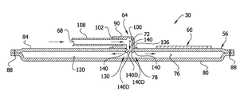
- FIG. 1is a top view of a compression garment as applied to a foot of a patient
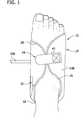
- FIG. 2is an exploded perspective of the compression garment of FIG. 1 ;
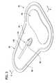
- FIG. 3is a bottom perspective of a first embodiment of a bladder assembly of the compression garment
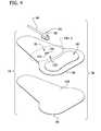
- FIG. 4is an exploded perspective of components of the bladder assembly of FIG. 3 ;
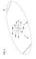
- FIG. 5is a plan view of an outer bladder sheet of the bladder assembly of FIG. 4 ;
- FIG. 6is a section of the bladder assembly taken in the plane including line 5 - 5 in FIG. 3 and illustrating air flow into the bladder assembly;
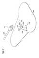
- FIG. 7is an exploded perspective of an outer bladder sheet, port and tube of the compression garment
- FIG. 8is a section of the bladder assembly of FIG. 7 similar to FIG. 3 ;
- FIG. 9is an exploded perspective of an outer bladder sheet, port and tube of the compression garment.
- FIG. 10is a section of the bladder assembly of FIG. 9 similar to FIG. 3 .
- a first embodiment of a compression garment in accordance with the present disclosureis illustrated as a foot cuff and is designated generally as 10 .
- the foot cuff 10is adapted for use in a compression therapy system for applying compressive pressure to a foot of a wearer, as is generally known in the art and will not be described herein.
- the foot cuff 10comprises a flexible member 14 configured to conform to the foot.
- the member 14includes an ankle strap 18 and is secured in a self-retaining configuration on the foot by two releasable fasteners 20 , 24 , which are described in more detail below.
- the foot cuff 10may have other configurations within the scope of the present invention.
- compression garments other than foot cuffsare within the scope of the present invention, including but not limited to leg compression sleeves, arm compression sleeves, and similar devices.
- the present inventionhas particular application to garments that are cyclically inflated and deflated, it could be used in garments having different uses, such as for treating edema, wound healing, etc.
- the flexible member 14comprises an inner (contact) layer 14 A and an outer layer 14 B secured to one another along a line 26 generally adjacent corresponding perimeters of the layers to define an interior space for receiving and substantially enclosing a bladder assembly, generally designated 30 .
- the inner and outer layers 14 A, 14 Bmay be fixedly secured to one another, such as by heat welding, adhesives, sewing, or other suitable ways. Alternatively, the layers 14 A and 14 B may be releasably secured to one another. In use, the inner layer 14 A is adjacent to the wearer's foot and the outer layer 14 B is located farthest from the foot.
- the terms “inner” and “outer”indicate relative positions of respective components and surfaces with respect to the skin of the wearer's body part when the compression garment is secured to the body part, and as such, an “inner” component or surface is more adjacent to the skin of the body part than an “outer” component or surface.
- the inner layer 14 A and the outer layer 14 B of the flexible member 14include ankle strap portions 18 A and 18 B respectively.
- the ankle strap portions 18 A, 18 Bhave a longitudinally projecting configuration for wrapping about a portion of the foot adjacent to the ankle.
- the ankle strap portions 18 A, 18 Bcan be sewn, RF welded, or sonic welded to respective inner and outer layers 14 A, 14 B.
- the ankle strap portions 18 A, 18 Bare formed as one piece with the inner layer 14 A and the outer layer 14 B, respectively.
- the inner layer 14 A of the flexible member 14is adapted for contacting the foot.
- this layer 14 Ais fabricated from a chemically treated material, with wicking ability, for wicking moisture away from the skin.
- the inner layer 14 Acan be faced with a soft material toward the treatment surface of the wearer.
- the soft materialcan be a thin layer of open celled porous foam, napped cloth, or a layer of vapor permeable cloth.
- flexible members 14 not including an inner layer 14 A or an outer layer 14 Bare within the scope of the present invention. Structure used to secure a bladder on a limb and maintain a position of the bladder can be a “flexible member.”
- the outer layer 14 B of the flexible member 14includes an opening 34 for allowing passage of pressurized air to the bladder assembly 30 .
- the outer layer 14 Bis configured for providing an attachment surface for a hook and loop feature of the foot cuff 10 , as will be described in more detail below.
- the outer layer 14 Bcomprises a soft material for cushioning the top portion of the foot and may be fabricated from similar materials as the inner layer 14 A and in similar dimensions therewith for corresponding geometry.
- the outer layer 14 Bmay be fabricated from a laminated material, such as, for example, thankara fabric, open cell urethane foam, or loop fabric.
- the releasable fasteners 20 , 24are positioned on and attached to the outer layer 14 B of the foot cuff for securing the foot cuff 10 around the foot.
- the first fastener 20comprises a tab 38 attached to the ankle strap portion 18 B of the outer layer 14 B of the foot cuff 10
- the second fastener 24comprises a tab 42 attached to a surface of the outer layer 14 B.
- Both straps 38 , 42have hook elements 50 .
- the hook elements 50 on the strapsengage loop elements (not shown) on the outer layer 14 B of the foot cuff 10 to secure the cuff on the foot, as will be understood by those skilled in the field familiar with foot cuffs.
- the releasable fasteners 20 , 24may have portions (not shown) without fastening material thereon to provide convenient gripping locations on the hook fasteners so that the practitioner can readily separate the hooks 50 from the outer layer 14 B.
- Other fastening structuremay be used without departing from the scope of the present invention.
- the bladder assembly 30is enveloped and enclosed by the flexible member 14 .
- the assembly 30comprises an inflatable bladder 56 , a substantially rigid sole 60 , and a port 64 having an air inlet 68 and air outlet 72 .
- the bladder 56defines an inflatable chamber 76 and has an opening 78 through which the inflatable chamber is inflated.
- the port 64is mounted on the bladder 56 and is adapted for communication with a source of pressurized air (not shown).
- the air outlet 72 of the port 64is in fluid communication with the inflatable chamber 76 via the opening 78 in the bladder 56 for delivery of air from the source of pressurized air into the inflatable chamber. Inflation of the inflatable chamber 76 applies a compression force to a foot of a wearer.
- the bladder 56includes inner and outer opposing sheets 80 , 84 of flexible air-impermeable material (e.g., PVC) joined together in a suitable manner along a line 88 adjacent to their peripheries to define the inflatable chamber 76 ( FIG. 5 ).
- the bladder 56is positioned on the flexible member 14 such that the inflatable chamber 76 underlies the sole of the foot when the foot cuff is placed on the foot.
- the inflatable chamber 76is adapted for receiving and retaining pressurized air for exerting compressive pressure on the foot during successive pressure application cycles, as will be understood by those skilled in this field.
- the opposing sheets 80 , 84 of the bladder 56are joined to one another in a suitable manner, such as by RF welding.
- Other ways of joining the sheets 80 , 84include sewing, adhesive, heat sealing, etc.
- the bladder 56can have other configurations within the scope of this invention.
- the bladdermay be formed from one or more sheets and/or may include more than one inflatable chamber.
- the sole 60 of the bladder assembly 30is a substantially rigid member positioned between the outer sheet 84 of the bladder 56 and the outer sheet 14 B of the flexible member 14 , and it extends generally lengthwise of the bottom of the foot when the foot cuff 10 is worn.
- the sole 60provides a substantially rigid foundation against which the bladder 56 reacts during expansion. As a result, the expansion of the bladder 56 is directed toward the inner layer 14 A of the flexible member 14 and the user's foot.
- the sole 60is secured by suitable structure to maintain it in proper position relative to the bladder 56 . It will be understood that the sole 60 may be omitted without departing from the scope of the present invention.
- the port 64comprises an elbow member 90 .
- the elbow member 90is of suitable material (e.g., plastic) and has passage 100 extending through it to permit flow of air from one end of the member 102 , constituting its inlet end, to an opposite end 106 of the member, constituting its outlet end.
- a tube 108is attached to the inlet 68 at the inlet end 102 of the elbow member 90 for connection to the source of pressurized air (e.g., an air compressor) for delivery of pressurized air to the elbow member.
- the outlet end 106 of the elbow member 90is attached to the outer sheet 84 of the bladder 56 , and is aligned with the opening 78 in the outer bladder sheet 84 for delivery of air into the inflatable chamber 76 of the bladder.
- the opening 78is described in further detail below.
- the tube 108is attached and sealed to the elbow member 90 by suitable means, such as heat sealing, RF welding, or adhesive, for example.
- the elbow member 90is attached and sealed to the bladder 56 by similar means, e.g., heat sealing, RF welding, solvent bond or adhesive.
- Other port configurationsare within the scope of the present invention.
- the bladder 56has an internal air impingement surface 120 inside the inflatable chamber 76 opposing the air outlet 72 of the port 64 .
- the air impingement surface 120is the surface of the inner bladder sheet 80 facing the inflatable chamber 76 .
- noiseis generated as pressurized air delivered through the bladder opening 78 impinges upon the impingement surface 120 .
- Noise attenuating means 130 associated with the bladder opening 78is provided for reducing noise from air flow into the inflatable chamber 76 and impinging against the impingement surface 120 .
- the noise attenuating means 130comprises four flaps 140 .
- the flaps 140are formed as one piece with the outer bladder sheet 84 .
- the bladder opening 78comprises two linear slits 144 that form an X-shape.
- each flap 140is generally triangular, having a base 140 A formed as one piece with the outer bladder sheet 84 and two free edges 140 B, 140 C forming a point 140 D.
- the flaps 140are flexible and air-impermeable.
- the flaps 140are positioned relative to the bladder opening 78 so that the flaps deflect when air is delivered into the inflatable chamber 76 through the bladder opening.
- the flaps 140overlie at least a portion of the air outlet 72 of the port 64 , and in the illustrated embodiment, the flaps overlie substantially all of the air outlet of the port.
- the flaps 140have a relaxed position in which the flaps are substantially parallel with the opening 78 in the bladder 56 . In this position, the free edges 140 B, 140 C of respective flaps 140 contact each other and the points 140 D of the flaps contact each other. As shown in FIG.
- the flaps 140are in registration with the port outlet 72 so that as air is delivered into the inflatable chamber 76 through the bladder opening 78 , the air moves the flaps 140 to a deflected position in which the flaps are not parallel to the bladder opening.
- the flaps 140diffuse or dissipate energy of the compressed air as it enters the inflatable chamber 76 , thus reducing noise generated during inflation of the inflatable chamber.
- the noise generationis reduced at least in part because the air entering the inflatable chamber 76 impinges upon the impingement surface 120 with less force.
- the flaps 140are preferably resilient so they move back to or near their relaxed position ( FIGS. 4 and 5 ) when air is not flowing into or out of the inflatable chamber 76 .
- the flaps 140allow air from within the inflatable chamber 76 to pass through the bladder opening 78 (e.g., deflect in an opposite direction than shown in FIG. 6 ) to deflate the inflatable chamber.
- a holee.g., a circular hole having a diameter of approximately 1 ⁇ 8 in. (0.32 cm)
- a holemay be formed at the intersection of the two slits 144 so that the points 140 D of the flaps 140 are truncated.
- Such a configurationallows air to move past the flaps 140 move easily and ensures the flaps do not act as a check valve that obstructs deflation of the bladder 56 .
- FIGS. 7 and 8illustrate a second embodiment of a bladder assembly 30 ′ of the present invention.
- the bladder assembly 30 ′is substantially similar to the bladder assembly 30 described above, and corresponding parts are generally indicated by the same reference numbers, plus a prime designator (′).
- the noise attenuating means 130 ′comprises a single flap 150 .
- the bladder opening 78 ′comprises a U-shaped slit 154 .
- the flap 150has a base 150 A formed as one piece with the outer bladder sheet 84 ′ and free edges comprising linear side edges 150 B, 150 C and a curved distal edge 150 D.
- the flap 150has a relaxed position ( FIG. 7 ) and a deflected position ( FIG. 8 ).
- the flap 150In the relaxed position, the flap 150 contacts an opposite edge 158 of the bladder opening 78 ′.
- the flap 150diffuses or dissipates energy of the compressed air as it enters the inflatable chamber 76 ′ from the port 64 ′, thus reducing the noise generated during inflation of the inflatable chamber.
- the distal edge 150 D of the flap 150may be truncated to provide an opening (not shown) between the flap and the opposite edge 158 of the bladder opening 78 ′ to allow air to flow more easily past the flap and ensure the flap does not act as a check valve that obstructs deflation of the bladder 56 .
- Flaps having other configurationsare within the scope of the present invention.
- the free edges 140 B, 140 Cneed not touch each other.
- free edges 150 B- 150 Dneed not contact an opposing edge 158 of the bladder opening 78 ′.
- the bladder openingmay comprise a gap between flaps and/or an opposing edge of the bladder opening.
- the slits 144 , 154 comprising the bladder opening 76 , 76 ′may be wider than illustrated.
- a multitude of other slit configurationsmay be used to define other shapes, sizes and/or numbers of flaps.
- Linear segments and/or curved segmentsmay be used to form any shape of slit.
- other slit configurationsmay comprise the shape of an E, H, K, M, N, T, W, Y, Z or asterisk.
- the flapsneed not be formed as one piece with the bladder. The flaps may be formed separately from the bladder and suitably secured in position relative to the port outlet, such as in the following embodiment.
- FIGS. 9 and 10illustrate a third embodiment of a bladder assembly 30 ′′ of the present invention.
- the bladder assembly 30 ′′is similar to the bladder assembly 30 described above, and corresponding parts are generally indicated by the same reference numbers, plus a double prime designator (′′).
- the noise attenuating means 130 ′′comprises an air diverter 170 positioned within the inflatable chamber 76 ′′. More specifically, the air diverter 170 is affixed to an inside surface 174 of the outer bladder sheet 84 ′′.
- the air diverter 170comprises a thin, flat panel, also designated 170 , and two segments or edge margins 170 A, 170 B of the panel are affixed to the inside surface 174 of the outer bladder sheet 84 ′′.
- Another edge margin 170 C of the panel 170overlies a portion of the bladder opening 78 ′′.
- the panel 170is positioned to divert air entering the inflatable chamber 76 ′′ from the port 64 ′′ through the bladder opening 78 ′′ from directly impinging against the impingement surface 120 ′′.
- a portion of the air entering the inflatable chamber 76 ′′ through the bladder opening 78 ′′bypasses the edge margin 170 C of the panel 170 that overlies the bladder opening and may impinge against the impingement surface 120 ′′.
- the panel 170channels air entering the inflatable chamber 76 through the bladder opening 78 ′′ along an upper surface 170 D of the panel 170 , between the two segments 170 A, 170 B affixed to the inside surface 174 of the outer bladder sheet 84 ′′.
- the affixed segments 170 A, 170 Bmay be spaced from one another so that the panel 170 is affixed to the outer bladder sheet 84 ′′ in a bowed fashion that facilitates flow of air between the panel and the outer bladder sheet.
- the panel 170may be made of a more rigid material (e.g., rigid plastic) relative to the material of the impingement surface 120 ′′. Air impinging against the panel 170 creates less noise because air impinging against the more rigid material of the panel creates fewer pressure waves in an audible range than if the air were impinging against the impingement surface 120 ′′. Moreover, the bladder opening 78 ′′ may be enlarged to overlie a greater portion of the upper surface 170 D of the panel 170 so that a larger percentage of the air passing into the inflatable chamber impinges against the panel to further reduce noise during inflation.
- a more rigid materiale.g., rigid plastic
- the panel 170is configured to allow air to pass from the inflatable chamber 76 ′′ through the bladder opening 78 ′′ to deflate the inflatable chamber.
- the panel 170allows air to pass from the inflatable chamber 76 ′′ through the bladder opening 78 ′′ because the panel does not overlie substantially all of the bladder opening. If the panel 170 were positioned to overlie substantially all of the bladder opening 78 ′′, the panel may act as a check valve that traps air inside the inflatable chamber 76 ′′.
- the foot cuff 10is fluidly connected to a compression therapy system (not shown). Compressed air is delivered to the bladder 56 of the foot cuff 10 via the port 64 and bladder opening 78 to apply compressive pressure to a foot of a wearer.
- Noise attenuating means 30 , 30 ′, 30 ′′, such as the flaps 140 , 150 or the air diverter 170may be used to reduce the noise generated during inflation of the inflatable chamber.
Landscapes
- Health & Medical Sciences (AREA)
- Animal Behavior & Ethology (AREA)
- Veterinary Medicine (AREA)
- Public Health (AREA)
- General Health & Medical Sciences (AREA)
- Life Sciences & Earth Sciences (AREA)
- Rehabilitation Therapy (AREA)
- Physical Education & Sports Medicine (AREA)
- Pain & Pain Management (AREA)
- Epidemiology (AREA)
- Nursing (AREA)
- Orthopedic Medicine & Surgery (AREA)
- Engineering & Computer Science (AREA)
- Biomedical Technology (AREA)
- Heart & Thoracic Surgery (AREA)
- Vascular Medicine (AREA)
- Massaging Devices (AREA)
Abstract
Description
Claims (10)
Priority Applications (2)
| Application Number | Priority Date | Filing Date | Title |
|---|---|---|---|
| US12/569,318US8469910B2 (en) | 2009-09-29 | 2009-09-29 | Pneumatic compression garment with noise attenuating means |
| US13/896,560US9033905B2 (en) | 2009-09-29 | 2013-05-17 | Pneumatic compression garment with noise attenuating means |
Applications Claiming Priority (1)
| Application Number | Priority Date | Filing Date | Title |
|---|---|---|---|
| US12/569,318US8469910B2 (en) | 2009-09-29 | 2009-09-29 | Pneumatic compression garment with noise attenuating means |
Related Child Applications (1)
| Application Number | Title | Priority Date | Filing Date |
|---|---|---|---|
| US13/896,560DivisionUS9033905B2 (en) | 2009-09-29 | 2013-05-17 | Pneumatic compression garment with noise attenuating means |
Publications (2)
| Publication Number | Publication Date |
|---|---|
| US20110077564A1 US20110077564A1 (en) | 2011-03-31 |
| US8469910B2true US8469910B2 (en) | 2013-06-25 |
Family
ID=43781127
Family Applications (2)
| Application Number | Title | Priority Date | Filing Date |
|---|---|---|---|
| US12/569,318Expired - Fee RelatedUS8469910B2 (en) | 2009-09-29 | 2009-09-29 | Pneumatic compression garment with noise attenuating means |
| US13/896,560Expired - Fee RelatedUS9033905B2 (en) | 2009-09-29 | 2013-05-17 | Pneumatic compression garment with noise attenuating means |
Family Applications After (1)
| Application Number | Title | Priority Date | Filing Date |
|---|---|---|---|
| US13/896,560Expired - Fee RelatedUS9033905B2 (en) | 2009-09-29 | 2013-05-17 | Pneumatic compression garment with noise attenuating means |
Country Status (1)
| Country | Link |
|---|---|
| US (2) | US8469910B2 (en) |
Cited By (2)
| Publication number | Priority date | Publication date | Assignee | Title |
|---|---|---|---|---|
| US20140277102A1 (en)* | 2013-03-15 | 2014-09-18 | Compression Therapy Concepts, Inc. | Deep Vein Thrombosis Prevention Garment Having Opposing Offset Attachment Straps |
| US9402779B2 (en) | 2013-03-11 | 2016-08-02 | Covidien Lp | Compression garment with perspiration relief |
Families Citing this family (5)
| Publication number | Priority date | Publication date | Assignee | Title |
|---|---|---|---|---|
| US8469910B2 (en) | 2009-09-29 | 2013-06-25 | Covidien Lp | Pneumatic compression garment with noise attenuating means |
| US9125787B2 (en) | 2011-09-30 | 2015-09-08 | Covidien Lp | Compression garment having a foam layer |
| CN108778155B (en)* | 2016-03-23 | 2021-04-06 | 泰尔茂株式会社 | Hemostatic instrument |
| JP6885941B2 (en)* | 2016-07-06 | 2021-06-16 | テルモ株式会社 | Hemostatic device |
| USD980445S1 (en)* | 2022-03-31 | 2023-03-07 | Shaojun Pan | Foot massage appliance |
Citations (78)
| Publication number | Priority date | Publication date | Assignee | Title |
|---|---|---|---|---|
| US3677300A (en) | 1970-01-15 | 1972-07-18 | Dunlop Holdings Ltd | Pressure reducing devices |
| US3736074A (en) | 1972-04-20 | 1973-05-29 | Worthington Cei | Inlet, filter and noise suppressor enclosure for compressing apparatus |
| US3855910A (en) | 1971-11-12 | 1974-12-24 | Robertson Bauelemente Gmbh | Acoustical ventilator |
| US3944084A (en) | 1974-11-01 | 1976-03-16 | Reeves Robert L | Means for preventing dry burn in a paper-plastic dunnage bag |
| US3946735A (en) | 1974-05-13 | 1976-03-30 | Dewall Richard A | Medical drainage device |
| US4135500A (en) | 1977-04-28 | 1979-01-23 | Medpro, Inc. | Apparatus for oscillating flotation support systems |
| US4264282A (en) | 1979-01-03 | 1981-04-28 | K. C. Mosier Company | Air compressor apparatus including noise-reducing means |
| US4399739A (en) | 1980-12-16 | 1983-08-23 | Tempmaster Corporation | Noise attenuating apparatus for modulating air flow |
| US4418443A (en) | 1981-12-07 | 1983-12-06 | Breuer Electric Mfg. Co. | Noise suppressor for vacuum sweepers and the like |
| US4435877A (en) | 1982-09-30 | 1984-03-13 | Shop-Vac Corporation | Noise reducing means for vacuum cleaner |
| US4450933A (en) | 1982-09-24 | 1984-05-29 | Kioritz Corporation | Suction silencer |
| US4534343A (en)* | 1984-01-27 | 1985-08-13 | Trutek Research, Inc. | Metered dose inhaler |
| US4606328A (en) | 1983-06-16 | 1986-08-19 | Thoman Evelyn B | Method and apparatus for treating breathing irregularities |
| GB2179968A (en) | 1985-09-06 | 1987-03-18 | Opti Patent Forschung Fab | Transport means for fastener stringers |
| US4729722A (en) | 1986-11-05 | 1988-03-08 | Can-Am Engineered Products, Inc. | Noise suppressor for turbo-compressor |
| US4872448A (en) | 1986-10-22 | 1989-10-10 | Johnson Jr Glenn W | Knee brace having adjustable inflatable U-shaped air cell |
| US4888003A (en) | 1988-02-29 | 1989-12-19 | Johnson Gerald W | Vacuum apparatus |
| US4911697A (en) | 1988-08-02 | 1990-03-27 | Sherwood Medical Company | Chest drainage unit having increased airflow capacity with capability to dampon noise |
| US4921477A (en) | 1987-10-14 | 1990-05-01 | The Cooper Companies, Inc. | Surgical irrigation and aspiration system with dampening device |
| US4991617A (en) | 1989-10-03 | 1991-02-12 | Seaco, Inc. | Gas inlet valve assembly for inflatable boats |
| US5047072A (en) | 1988-11-10 | 1991-09-10 | Surgical Laser Products, Inc. | Ultraviolet air enhancement and laser plume evacuation method and system |
| US5118262A (en) | 1991-04-01 | 1992-06-02 | Kuo Shui Long | Multi-function combination air compressor |
| US5147243A (en) | 1991-05-10 | 1992-09-15 | Carrier Corporation | Air terminal apparatus |
| US5174127A (en) | 1990-11-13 | 1992-12-29 | Tecumseh Products Company | Suction muffler tube |
| US5214253A (en) | 1990-10-26 | 1993-05-25 | Houston Jr Richard G | Automotive exhaust system |
| US5260524A (en) | 1992-05-14 | 1993-11-09 | The Coca-Cola Company | Muffler for air compressor and method |
| US5285791A (en) | 1992-01-21 | 1994-02-15 | Siemens Medical Electronics, Inc. | Noise damping system for an automatic blood pressure gauge |
| GB2271060A (en) | 1992-10-01 | 1994-04-06 | Huntleigh Technology Plc | An inflatable compression garment. |
| US5353525A (en) | 1989-02-14 | 1994-10-11 | Vistek, Inc. | Variable support shoe |
| US5354260A (en) | 1993-05-13 | 1994-10-11 | Novamedix, Ltd. | Slipper with an inflatable foot pump |
| US5449379A (en) | 1993-07-21 | 1995-09-12 | Alternative Compression Technologies, Inc. | Apparatus for applying a desired temperature and pressure to an injured area |
| US5599333A (en) | 1994-12-29 | 1997-02-04 | Zimmer, Inc. | Suction adapter |
| US5628306A (en)* | 1992-10-19 | 1997-05-13 | Kee; Kok-Hiong | Respiratory manifold with accessory access port |
| US5804777A (en) | 1995-11-02 | 1998-09-08 | Lg Electronics Inc. | Suction noise muffler for hermetic compressor |
| US5858062A (en) | 1997-02-10 | 1999-01-12 | Litton Systems, Inc. | Oxygen concentrator |
| EP0897707A2 (en) | 1997-08-09 | 1999-02-24 | Huntleigh Technology Plc | Compression system |
| US5961309A (en) | 1997-04-24 | 1999-10-05 | Trw Inc. | Gear pump with noise attenuation |
| US5996731A (en) | 1998-02-24 | 1999-12-07 | Czabala; Michael P. | Compressor muffler |
| US6089346A (en) | 1999-06-02 | 2000-07-18 | 3M Innovative Properties Company | Muffler with acoustic barrier material for limited clearance pneumatic device applications |
| US6126393A (en) | 1995-09-08 | 2000-10-03 | Augustine Medical, Inc. | Low noise air blower unit for inflating blankets |
| US6231009B1 (en)* | 1998-12-16 | 2001-05-15 | Carl Cheung Tung Kong | Fluid transfer system |
| US6280153B1 (en) | 1999-05-22 | 2001-08-28 | Danfoss Compressors Gmbh | Suction gas conduit for a refrigeration compressor |
| US6340069B1 (en) | 2000-07-19 | 2002-01-22 | Meiko Pet Corporation | Sound elimination structure for air pump |
| US6382931B1 (en) | 1998-02-24 | 2002-05-07 | Respironics, Inc. | Compressor muffler |
| US20020085931A1 (en) | 2000-12-28 | 2002-07-04 | Lee In Seop | Compressor |
| US6447491B1 (en) | 1999-06-18 | 2002-09-10 | Genzyme Corporation | Rolling seal suction pressure regulator, apparatus and system for draining a body cavity and methods related thereto |
| US6558137B2 (en) | 2000-12-01 | 2003-05-06 | Tecumseh Products Company | Reciprocating piston compressor having improved noise attenuation |
| US6623239B2 (en) | 2000-12-13 | 2003-09-23 | Honeywell International Inc. | Turbocharger noise deflector |
| US6663596B2 (en)* | 2001-08-13 | 2003-12-16 | Scimed Life Systems, Inc. | Delivering material to a patient |
| US6682317B2 (en) | 2002-06-20 | 2004-01-27 | Ding Hua Co., Ltd. | Miniature air compressor |
| US6702880B2 (en) | 2002-05-17 | 2004-03-09 | Porous Media Corporation | Inlet silencer/filter for an oxygen concentrator |
| US6740066B2 (en) | 1999-03-26 | 2004-05-25 | Brunel University | Urine collection device |
| US6743250B2 (en) | 2001-02-28 | 2004-06-01 | William Leonard Renfro | Portable thermal rescue/recovery system |
| US20040126247A1 (en) | 2002-10-16 | 2004-07-01 | Dietmar Broser | Muffler for air compressor |
| US20040261621A1 (en) | 2003-06-26 | 2004-12-30 | Lindsay William S. | Disposable filtering and muffling assembly |
| US6840746B2 (en) | 2002-07-02 | 2005-01-11 | Bristol Compressors, Inc. | Resistive suction muffler for refrigerant compressors |
| US6866700B2 (en) | 2002-08-27 | 2005-03-15 | Ag Industries | Filter housing assembly for use in oxygen concentrators and other compressors |
| US20050067218A1 (en) | 2001-11-21 | 2005-03-31 | Dunlop Aerospace Limited | Noise attenuator arrangement |
| US6935460B2 (en) | 2003-05-21 | 2005-08-30 | Airsep Corporation | Noise muffler for oxygen concentrator |
| US6966198B2 (en) | 2003-12-12 | 2005-11-22 | Visteon Global Technologies, Inc. | Air-cycle air conditioning system for commercial refrigeration |
| US20060111655A1 (en) | 2002-08-02 | 2006-05-25 | Gordon Cook | Inflatable device for use in impulse therapy |
| US7070567B2 (en) | 2003-04-21 | 2006-07-04 | Colin Medical Technology Corporation | Inflatable cuff for blood pressure measurement |
| US20060251527A1 (en) | 2005-05-06 | 2006-11-09 | Wester Paul M | Noise suppressor for air compressor |
| US7141101B2 (en) | 2004-06-17 | 2006-11-28 | Home Health Medical Equipment Incorporated | Filter assembly with noise attenuation |
| US7153107B1 (en) | 2004-10-01 | 2006-12-26 | Ric Investments, Llc | Compressor muffler assembly |
| US20070019047A1 (en)* | 2003-09-10 | 2007-01-25 | Kmp Printtechnik Ag | Ink cartridge |
| US20070135743A1 (en)* | 2005-12-12 | 2007-06-14 | Ann Meyer | Compression apparatus |
| US20070276313A1 (en)* | 2003-08-29 | 2007-11-29 | Moorehead H R | Valved Catheters Including High Flow Rate Catheters |
| US20070290012A1 (en)* | 2004-01-20 | 2007-12-20 | Jackman Brian F | Pressure activated self opening container and seal |
| US20080030747A1 (en) | 2006-08-02 | 2008-02-07 | Seiko Epson Corporation | Printing apparatus and printing method |
| US20080082059A1 (en) | 2006-09-28 | 2008-04-03 | David Fink | Portable wound therapy system |
| US20080087169A1 (en) | 2006-10-11 | 2008-04-17 | Clark Steven G | Air filtering assembly for use with oxygen concentrating equipment |
| US20080103422A1 (en) | 2004-02-23 | 2008-05-01 | Tyco Healthcare Group Lp | Garment Detection Method and System for Delivering Compression Treatment |
| US20080200872A1 (en) | 2007-01-16 | 2008-08-21 | Isham John | Minimally invasive rectal balloon apparatus |
| US7431571B2 (en) | 2001-11-16 | 2008-10-07 | Lg Electronics Inc. | Noise reduction muffler for hermetic rotary compressor |
| US7452340B2 (en) | 2003-12-31 | 2008-11-18 | Novamedix Distribution Limited | Garment for use in pump therapy for enhancing venous and arterial blood flow |
| US20110077565A1 (en)* | 2009-09-29 | 2011-03-31 | Tyco Healthcare Group Lp | Reduced noise pneumatic compression garment |
| US7967766B2 (en) | 2005-10-27 | 2011-06-28 | Sundaram Ravikumar | Compression garment with heel elevation |
Family Cites Families (4)
| Publication number | Priority date | Publication date | Assignee | Title |
|---|---|---|---|---|
| US5840400A (en)* | 1989-12-04 | 1998-11-24 | Supracor Systems, Inc. | Perforated core honeycomb panel system |
| US8029451B2 (en) | 2005-12-12 | 2011-10-04 | Tyco Healthcare Group Lp | Compression sleeve having air conduits |
| US8469910B2 (en) | 2009-09-29 | 2013-06-25 | Covidien Lp | Pneumatic compression garment with noise attenuating means |
| US8328741B2 (en) | 2009-09-29 | 2012-12-11 | Covidien Lp | Pneumatic compression garment with noise attenuating means |
- 2009
- 2009-09-29USUS12/569,318patent/US8469910B2/ennot_activeExpired - Fee Related
- 2013
- 2013-05-17USUS13/896,560patent/US9033905B2/ennot_activeExpired - Fee Related
Patent Citations (79)
| Publication number | Priority date | Publication date | Assignee | Title |
|---|---|---|---|---|
| US3677300A (en) | 1970-01-15 | 1972-07-18 | Dunlop Holdings Ltd | Pressure reducing devices |
| US3855910A (en) | 1971-11-12 | 1974-12-24 | Robertson Bauelemente Gmbh | Acoustical ventilator |
| US3736074A (en) | 1972-04-20 | 1973-05-29 | Worthington Cei | Inlet, filter and noise suppressor enclosure for compressing apparatus |
| US3946735A (en) | 1974-05-13 | 1976-03-30 | Dewall Richard A | Medical drainage device |
| US3944084A (en) | 1974-11-01 | 1976-03-16 | Reeves Robert L | Means for preventing dry burn in a paper-plastic dunnage bag |
| US4135500A (en) | 1977-04-28 | 1979-01-23 | Medpro, Inc. | Apparatus for oscillating flotation support systems |
| US4264282A (en) | 1979-01-03 | 1981-04-28 | K. C. Mosier Company | Air compressor apparatus including noise-reducing means |
| US4399739A (en) | 1980-12-16 | 1983-08-23 | Tempmaster Corporation | Noise attenuating apparatus for modulating air flow |
| US4418443A (en) | 1981-12-07 | 1983-12-06 | Breuer Electric Mfg. Co. | Noise suppressor for vacuum sweepers and the like |
| US4450933A (en) | 1982-09-24 | 1984-05-29 | Kioritz Corporation | Suction silencer |
| US4435877A (en) | 1982-09-30 | 1984-03-13 | Shop-Vac Corporation | Noise reducing means for vacuum cleaner |
| US4606328A (en) | 1983-06-16 | 1986-08-19 | Thoman Evelyn B | Method and apparatus for treating breathing irregularities |
| US4534343A (en)* | 1984-01-27 | 1985-08-13 | Trutek Research, Inc. | Metered dose inhaler |
| GB2179968A (en) | 1985-09-06 | 1987-03-18 | Opti Patent Forschung Fab | Transport means for fastener stringers |
| US4872448A (en) | 1986-10-22 | 1989-10-10 | Johnson Jr Glenn W | Knee brace having adjustable inflatable U-shaped air cell |
| US4729722A (en) | 1986-11-05 | 1988-03-08 | Can-Am Engineered Products, Inc. | Noise suppressor for turbo-compressor |
| US4921477A (en) | 1987-10-14 | 1990-05-01 | The Cooper Companies, Inc. | Surgical irrigation and aspiration system with dampening device |
| US4888003A (en) | 1988-02-29 | 1989-12-19 | Johnson Gerald W | Vacuum apparatus |
| US4911697A (en) | 1988-08-02 | 1990-03-27 | Sherwood Medical Company | Chest drainage unit having increased airflow capacity with capability to dampon noise |
| US5047072A (en) | 1988-11-10 | 1991-09-10 | Surgical Laser Products, Inc. | Ultraviolet air enhancement and laser plume evacuation method and system |
| US5353525A (en) | 1989-02-14 | 1994-10-11 | Vistek, Inc. | Variable support shoe |
| US4991617A (en) | 1989-10-03 | 1991-02-12 | Seaco, Inc. | Gas inlet valve assembly for inflatable boats |
| US5214253A (en) | 1990-10-26 | 1993-05-25 | Houston Jr Richard G | Automotive exhaust system |
| US5174127A (en) | 1990-11-13 | 1992-12-29 | Tecumseh Products Company | Suction muffler tube |
| US5118262A (en) | 1991-04-01 | 1992-06-02 | Kuo Shui Long | Multi-function combination air compressor |
| US5147243A (en) | 1991-05-10 | 1992-09-15 | Carrier Corporation | Air terminal apparatus |
| US5285791A (en) | 1992-01-21 | 1994-02-15 | Siemens Medical Electronics, Inc. | Noise damping system for an automatic blood pressure gauge |
| US5260524A (en) | 1992-05-14 | 1993-11-09 | The Coca-Cola Company | Muffler for air compressor and method |
| GB2271060A (en) | 1992-10-01 | 1994-04-06 | Huntleigh Technology Plc | An inflatable compression garment. |
| US5628306A (en)* | 1992-10-19 | 1997-05-13 | Kee; Kok-Hiong | Respiratory manifold with accessory access port |
| US5354260A (en) | 1993-05-13 | 1994-10-11 | Novamedix, Ltd. | Slipper with an inflatable foot pump |
| US5449379A (en) | 1993-07-21 | 1995-09-12 | Alternative Compression Technologies, Inc. | Apparatus for applying a desired temperature and pressure to an injured area |
| US5599333A (en) | 1994-12-29 | 1997-02-04 | Zimmer, Inc. | Suction adapter |
| US6126393A (en) | 1995-09-08 | 2000-10-03 | Augustine Medical, Inc. | Low noise air blower unit for inflating blankets |
| US5804777A (en) | 1995-11-02 | 1998-09-08 | Lg Electronics Inc. | Suction noise muffler for hermetic compressor |
| US5858062A (en) | 1997-02-10 | 1999-01-12 | Litton Systems, Inc. | Oxygen concentrator |
| US5961309A (en) | 1997-04-24 | 1999-10-05 | Trw Inc. | Gear pump with noise attenuation |
| EP0897707A2 (en) | 1997-08-09 | 1999-02-24 | Huntleigh Technology Plc | Compression system |
| US5996731A (en) | 1998-02-24 | 1999-12-07 | Czabala; Michael P. | Compressor muffler |
| US6382931B1 (en) | 1998-02-24 | 2002-05-07 | Respironics, Inc. | Compressor muffler |
| US6231009B1 (en)* | 1998-12-16 | 2001-05-15 | Carl Cheung Tung Kong | Fluid transfer system |
| US6740066B2 (en) | 1999-03-26 | 2004-05-25 | Brunel University | Urine collection device |
| US6280153B1 (en) | 1999-05-22 | 2001-08-28 | Danfoss Compressors Gmbh | Suction gas conduit for a refrigeration compressor |
| US6089346A (en) | 1999-06-02 | 2000-07-18 | 3M Innovative Properties Company | Muffler with acoustic barrier material for limited clearance pneumatic device applications |
| US6447491B1 (en) | 1999-06-18 | 2002-09-10 | Genzyme Corporation | Rolling seal suction pressure regulator, apparatus and system for draining a body cavity and methods related thereto |
| US6340069B1 (en) | 2000-07-19 | 2002-01-22 | Meiko Pet Corporation | Sound elimination structure for air pump |
| US6558137B2 (en) | 2000-12-01 | 2003-05-06 | Tecumseh Products Company | Reciprocating piston compressor having improved noise attenuation |
| US6623239B2 (en) | 2000-12-13 | 2003-09-23 | Honeywell International Inc. | Turbocharger noise deflector |
| US20020085931A1 (en) | 2000-12-28 | 2002-07-04 | Lee In Seop | Compressor |
| US6743250B2 (en) | 2001-02-28 | 2004-06-01 | William Leonard Renfro | Portable thermal rescue/recovery system |
| US6663596B2 (en)* | 2001-08-13 | 2003-12-16 | Scimed Life Systems, Inc. | Delivering material to a patient |
| US7431571B2 (en) | 2001-11-16 | 2008-10-07 | Lg Electronics Inc. | Noise reduction muffler for hermetic rotary compressor |
| US20050067218A1 (en) | 2001-11-21 | 2005-03-31 | Dunlop Aerospace Limited | Noise attenuator arrangement |
| US6702880B2 (en) | 2002-05-17 | 2004-03-09 | Porous Media Corporation | Inlet silencer/filter for an oxygen concentrator |
| US6682317B2 (en) | 2002-06-20 | 2004-01-27 | Ding Hua Co., Ltd. | Miniature air compressor |
| US6840746B2 (en) | 2002-07-02 | 2005-01-11 | Bristol Compressors, Inc. | Resistive suction muffler for refrigerant compressors |
| US20060111655A1 (en) | 2002-08-02 | 2006-05-25 | Gordon Cook | Inflatable device for use in impulse therapy |
| US6866700B2 (en) | 2002-08-27 | 2005-03-15 | Ag Industries | Filter housing assembly for use in oxygen concentrators and other compressors |
| US20040126247A1 (en) | 2002-10-16 | 2004-07-01 | Dietmar Broser | Muffler for air compressor |
| US7070567B2 (en) | 2003-04-21 | 2006-07-04 | Colin Medical Technology Corporation | Inflatable cuff for blood pressure measurement |
| US6935460B2 (en) | 2003-05-21 | 2005-08-30 | Airsep Corporation | Noise muffler for oxygen concentrator |
| US20040261621A1 (en) | 2003-06-26 | 2004-12-30 | Lindsay William S. | Disposable filtering and muffling assembly |
| US20070276313A1 (en)* | 2003-08-29 | 2007-11-29 | Moorehead H R | Valved Catheters Including High Flow Rate Catheters |
| US20070019047A1 (en)* | 2003-09-10 | 2007-01-25 | Kmp Printtechnik Ag | Ink cartridge |
| US6966198B2 (en) | 2003-12-12 | 2005-11-22 | Visteon Global Technologies, Inc. | Air-cycle air conditioning system for commercial refrigeration |
| US7452340B2 (en) | 2003-12-31 | 2008-11-18 | Novamedix Distribution Limited | Garment for use in pump therapy for enhancing venous and arterial blood flow |
| US20070290012A1 (en)* | 2004-01-20 | 2007-12-20 | Jackman Brian F | Pressure activated self opening container and seal |
| US20080103422A1 (en) | 2004-02-23 | 2008-05-01 | Tyco Healthcare Group Lp | Garment Detection Method and System for Delivering Compression Treatment |
| US7141101B2 (en) | 2004-06-17 | 2006-11-28 | Home Health Medical Equipment Incorporated | Filter assembly with noise attenuation |
| US7153107B1 (en) | 2004-10-01 | 2006-12-26 | Ric Investments, Llc | Compressor muffler assembly |
| US20060251527A1 (en) | 2005-05-06 | 2006-11-09 | Wester Paul M | Noise suppressor for air compressor |
| US7967766B2 (en) | 2005-10-27 | 2011-06-28 | Sundaram Ravikumar | Compression garment with heel elevation |
| US20070135743A1 (en)* | 2005-12-12 | 2007-06-14 | Ann Meyer | Compression apparatus |
| US7931606B2 (en) | 2005-12-12 | 2011-04-26 | Tyco Healthcare Group Lp | Compression apparatus |
| US20080030747A1 (en) | 2006-08-02 | 2008-02-07 | Seiko Epson Corporation | Printing apparatus and printing method |
| US20080082059A1 (en) | 2006-09-28 | 2008-04-03 | David Fink | Portable wound therapy system |
| US20080087169A1 (en) | 2006-10-11 | 2008-04-17 | Clark Steven G | Air filtering assembly for use with oxygen concentrating equipment |
| US20080200872A1 (en) | 2007-01-16 | 2008-08-21 | Isham John | Minimally invasive rectal balloon apparatus |
| US20110077565A1 (en)* | 2009-09-29 | 2011-03-31 | Tyco Healthcare Group Lp | Reduced noise pneumatic compression garment |
Cited By (2)
| Publication number | Priority date | Publication date | Assignee | Title |
|---|---|---|---|---|
| US9402779B2 (en) | 2013-03-11 | 2016-08-02 | Covidien Lp | Compression garment with perspiration relief |
| US20140277102A1 (en)* | 2013-03-15 | 2014-09-18 | Compression Therapy Concepts, Inc. | Deep Vein Thrombosis Prevention Garment Having Opposing Offset Attachment Straps |
Also Published As
| Publication number | Publication date |
|---|---|
| US20140142481A1 (en) | 2014-05-22 |
| US9033905B2 (en) | 2015-05-19 |
| US20110077564A1 (en) | 2011-03-31 |
Similar Documents
| Publication | Publication Date | Title |
|---|---|---|
| US9033905B2 (en) | Pneumatic compression garment with noise attenuating means | |
| EP2301496B1 (en) | Pneumatic compression garment with noise attenuating means | |
| EP2140850B1 (en) | Inflatable member for compression foot cuff | |
| US20080306420A1 (en) | Compression device with independently moveable inflatable member | |
| US8562549B2 (en) | Compression device having an inflatable member including a frame member | |
| US7931606B2 (en) | Compression apparatus | |
| US8313450B2 (en) | Inflatable compression sleeve | |
| US8162863B2 (en) | Sole with anchor for compression foot cuff | |
| US20070282233A1 (en) | Compression apparatus | |
| TWI501755B (en) | Compression system with vent cooling feature | |
| US20060020236A1 (en) | Disposable compression sleeve | |
| ES2441234T3 (en) | Bladder tube connection | |
| US9572720B2 (en) | Reduced noise pneumatic compression garment | |
| EP2098210A1 (en) | Compression device having an inflatable member with a pocket for receiving a counterforce component | |
| EP2098214B1 (en) | Sole with anchor for compression foot cuff | |
| EP2098211B1 (en) | Compression foot cuff |
Legal Events
| Date | Code | Title | Description |
|---|---|---|---|
| AS | Assignment | Owner name:TYCO HEALTHCARE GROUP LP, MASSACHUSETTS Free format text:ASSIGNMENT OF ASSIGNORS INTEREST;ASSIGNORS:GANAPATHY, PREMNARAYAN;NARDI, STEVE;BECKER, PAUL;REEL/FRAME:023299/0044 Effective date:20090918 | |
| AS | Assignment | Owner name:COVIDIEN LP, MASSACHUSETTS Free format text:CHANGE OF NAME;ASSIGNOR:TYCO HEALTHCARE GROUP LP;REEL/FRAME:029595/0101 Effective date:20120928 | |
| STCF | Information on status: patent grant | Free format text:PATENTED CASE | |
| FPAY | Fee payment | Year of fee payment:4 | |
| AS | Assignment | Owner name:KPR U.S., LLC, MASSACHUSETTS Free format text:ASSIGNMENT OF ASSIGNORS INTEREST;ASSIGNOR:COVIDIEN LP;REEL/FRAME:044129/0389 Effective date:20170728 | |
| MAFP | Maintenance fee payment | Free format text:PAYMENT OF MAINTENANCE FEE, 8TH YEAR, LARGE ENTITY (ORIGINAL EVENT CODE: M1552); ENTITY STATUS OF PATENT OWNER: LARGE ENTITY Year of fee payment:8 | |
| FEPP | Fee payment procedure | Free format text:MAINTENANCE FEE REMINDER MAILED (ORIGINAL EVENT CODE: REM.); ENTITY STATUS OF PATENT OWNER: LARGE ENTITY | |
| LAPS | Lapse for failure to pay maintenance fees | Free format text:PATENT EXPIRED FOR FAILURE TO PAY MAINTENANCE FEES (ORIGINAL EVENT CODE: EXP.); ENTITY STATUS OF PATENT OWNER: LARGE ENTITY | |
| STCH | Information on status: patent discontinuation | Free format text:PATENT EXPIRED DUE TO NONPAYMENT OF MAINTENANCE FEES UNDER 37 CFR 1.362 | |
| FP | Lapsed due to failure to pay maintenance fee | Effective date:20250625 |