US8469244B2 - Overcap and system for spraying a fluid - Google Patents
Overcap and system for spraying a fluidDownload PDFInfo
- Publication number
- US8469244B2 US8469244B2US11/893,476US89347607AUS8469244B2US 8469244 B2US8469244 B2US 8469244B2US 89347607 AUS89347607 AUS 89347607AUS 8469244 B2US8469244 B2US 8469244B2
- Authority
- US
- United States
- Prior art keywords
- displacement member
- valve stem
- overcap
- container
- housing
- Prior art date
- Legal status (The legal status is an assumption and is not a legal conclusion. Google has not performed a legal analysis and makes no representation as to the accuracy of the status listed.)
- Active, expires
Links
- 239000012530fluidSubstances0.000titleclaimsdescription28
- 238000005507sprayingMethods0.000titledescription18
- 239000000463materialSubstances0.000claimsabstractdescription10
- 230000004044responseEffects0.000claimsabstractdescription10
- 238000006073displacement reactionMethods0.000claimsdescription72
- 238000012546transferMethods0.000claimsdescription39
- 230000004913activationEffects0.000claimsdescription22
- 238000004891communicationMethods0.000claimsdescription12
- 239000000443aerosolSubstances0.000description20
- 230000002093peripheral effectEffects0.000description7
- 230000007613environmental effectEffects0.000description5
- 230000007246mechanismEffects0.000description5
- NJPPVKZQTLUDBO-UHFFFAOYSA-NnovaluronChemical compoundC1=C(Cl)C(OC(F)(F)C(OC(F)(F)F)F)=CC=C1NC(=O)NC(=O)C1=C(F)C=CC=C1FNJPPVKZQTLUDBO-UHFFFAOYSA-N0.000description4
- 230000000717retained effectEffects0.000description4
- 239000002386air freshenerSubstances0.000description3
- 230000003466anti-cipated effectEffects0.000description3
- 230000008859changeEffects0.000description3
- 230000000694effectsEffects0.000description3
- 239000002917insecticideSubstances0.000description3
- 239000007788liquidSubstances0.000description3
- 239000004479aerosol dispenserSubstances0.000description2
- 238000007906compressionMethods0.000description2
- 230000006835compressionEffects0.000description2
- 239000000850decongestantSubstances0.000description2
- 229940124581decongestantsDrugs0.000description2
- 239000002781deodorant agentSubstances0.000description2
- 238000013461designMethods0.000description2
- 238000010586diagramMethods0.000description2
- 230000002070germicidal effectEffects0.000description2
- -1germicidesSubstances0.000description2
- 230000003993interactionEffects0.000description2
- 230000014759maintenance of locationEffects0.000description2
- 238000004519manufacturing processMethods0.000description2
- 238000012986modificationMethods0.000description2
- 230000004048modificationEffects0.000description2
- 239000002304perfumeSubstances0.000description2
- 230000003213activating effectEffects0.000description1
- 230000009286beneficial effectEffects0.000description1
- 230000004397blinkingEffects0.000description1
- OJIJEKBXJYRIBZ-UHFFFAOYSA-Ncadmium nickelChemical compound[Ni].[Cd]OJIJEKBXJYRIBZ-UHFFFAOYSA-N0.000description1
- 238000010276constructionMethods0.000description1
- 230000003247decreasing effectEffects0.000description1
- 230000001877deodorizing effectEffects0.000description1
- 230000000881depressing effectEffects0.000description1
- 238000011161developmentMethods0.000description1
- 238000007599dischargingMethods0.000description1
- 238000001914filtrationMethods0.000description1
- 238000009472formulationMethods0.000description1
- 239000003205fragranceSubstances0.000description1
- 238000005286illuminationMethods0.000description1
- 230000006872improvementEffects0.000description1
- 239000003112inhibitorSubstances0.000description1
- 239000000077insect repellentSubstances0.000description1
- 230000002045lasting effectEffects0.000description1
- 238000000034methodMethods0.000description1
- 239000000203mixtureSubstances0.000description1
- 238000011160researchMethods0.000description1
- 239000007921spraySubstances0.000description1
- 238000013519translationMethods0.000description1
- 230000000007visual effectEffects0.000description1
Images


Classifications
- B—PERFORMING OPERATIONS; TRANSPORTING
- B65—CONVEYING; PACKING; STORING; HANDLING THIN OR FILAMENTARY MATERIAL
- B65D—CONTAINERS FOR STORAGE OR TRANSPORT OF ARTICLES OR MATERIALS, e.g. BAGS, BARRELS, BOTTLES, BOXES, CANS, CARTONS, CRATES, DRUMS, JARS, TANKS, HOPPERS, FORWARDING CONTAINERS; ACCESSORIES, CLOSURES, OR FITTINGS THEREFOR; PACKAGING ELEMENTS; PACKAGES
- B65D83/00—Containers or packages with special means for dispensing contents
- B65D83/14—Containers for dispensing liquid or semi-liquid contents by internal gaseous pressure, i.e. aerosol containers comprising propellant
- B65D83/16—Actuating means
- B65D83/26—Actuating means operating automatically, e.g. periodically
- B65D83/262—Actuating means operating automatically, e.g. periodically by clockwork, motor, electric or magnetic means operating without repeated human input
- A—HUMAN NECESSITIES
- A61—MEDICAL OR VETERINARY SCIENCE; HYGIENE
- A61L—METHODS OR APPARATUS FOR STERILISING MATERIALS OR OBJECTS IN GENERAL; DISINFECTION, STERILISATION OR DEODORISATION OF AIR; CHEMICAL ASPECTS OF BANDAGES, DRESSINGS, ABSORBENT PADS OR SURGICAL ARTICLES; MATERIALS FOR BANDAGES, DRESSINGS, ABSORBENT PADS OR SURGICAL ARTICLES
- A61L9/00—Disinfection, sterilisation or deodorisation of air
- A61L9/14—Disinfection, sterilisation or deodorisation of air using sprayed or atomised substances including air-liquid contact processes
- B—PERFORMING OPERATIONS; TRANSPORTING
- B05—SPRAYING OR ATOMISING IN GENERAL; APPLYING FLUENT MATERIALS TO SURFACES, IN GENERAL
- B05B—SPRAYING APPARATUS; ATOMISING APPARATUS; NOZZLES
- B05B12/00—Arrangements for controlling delivery; Arrangements for controlling the spray area
- B05B12/08—Arrangements for controlling delivery; Arrangements for controlling the spray area responsive to condition of liquid or other fluent material to be discharged, of ambient medium or of target ; responsive to condition of spray devices or of supply means, e.g. pipes, pumps or their drive means
- B05B12/12—Arrangements for controlling delivery; Arrangements for controlling the spray area responsive to condition of liquid or other fluent material to be discharged, of ambient medium or of target ; responsive to condition of spray devices or of supply means, e.g. pipes, pumps or their drive means responsive to conditions of ambient medium or target, e.g. humidity, temperature position or movement of the target relative to the spray apparatus
- B—PERFORMING OPERATIONS; TRANSPORTING
- B65—CONVEYING; PACKING; STORING; HANDLING THIN OR FILAMENTARY MATERIAL
- B65D—CONTAINERS FOR STORAGE OR TRANSPORT OF ARTICLES OR MATERIALS, e.g. BAGS, BARRELS, BOTTLES, BOXES, CANS, CARTONS, CRATES, DRUMS, JARS, TANKS, HOPPERS, FORWARDING CONTAINERS; ACCESSORIES, CLOSURES, OR FITTINGS THEREFOR; PACKAGING ELEMENTS; PACKAGES
- B65D83/00—Containers or packages with special means for dispensing contents
- B65D83/14—Containers for dispensing liquid or semi-liquid contents by internal gaseous pressure, i.e. aerosol containers comprising propellant
- B65D83/44—Valves specially adapted for the discharge of contents; Regulating devices
- B65D83/46—Tilt valves
Definitions
- the present disclosurerelates generally to an overcap for a container, and more particularly to an overcap adapted to be placed on an aerosol container having a tilt-activated valve stem.
- Aerosol containersare commonly used to store and dispense volatile materials such as air fresheners, deodorants, insecticides, germicides, decongestants, perfumes, and the like.
- volatile materialssuch as air fresheners, deodorants, insecticides, germicides, decongestants, perfumes, and the like.
- the volatile materialis stored under compression and typically in a liquid state within a container.
- a release valve on the containercontrols release of the volatile material contained under compression therein.
- the release valvetypically has a valve stem that outwardly extends from the valve, wherein the valve is activated by the valve stem and the volatile material flows out of the container through the valve stem. In such a release valve, the valve is activated by a displacement of the valve stem with respect to a valve body.
- the valve stemmay be displaced along a longitudinal axis of the valve stem, i.e., axially, or the valve stem may be tilted or displaced in a direction transverse to the longitudinal axis of the valve stem, i.e., radially.
- Activation of a release valvemay be accomplished by an automated system or manually.
- manual activationa user may adjust an activation force applied to the valve as required to achieve a desired release. Therefore, consideration of applied force requirements is generally less important to design of manually activated release valves.
- Conventional actuator mechanismsmay include motor driven linkages that apply downward pressure to depress the nozzle and open the valve within the container. Typically, these actuator mechanisms are unwieldy and are not readily adaptable to be used in a stand-alone manner and a hand-held manner. Further, many of these actuator mechanisms exhibit a great deal of power consumption. Generally, valves having tilt-activated valve stems require less force for activation than valves having vertically activated valve stems.
- a volatile material dispenserincludes a housing adapted to be releasably mounted on a container having a tilt-activated valve stem.
- the housingincludes a discharge orifice.
- a drive unitis disposed within the housing, wherein the drive unit is activated in response to a signal from at least a sensor, and wherein the drive unit is adapted to radially displace the tilt-activated valve stem in response to the signal.
- an overcap for a volatile material containerincludes a housing adapted to be releasably mounted on a container having a tilt-activated valve stem.
- a displacement memberis disposed within the housing, wherein a first end of the displacement member is adapted to be disposed on the tilt-activated valve stem and a second end is in fluid communication the first end.
- a flangeextends radially from the displacement member.
- a drive unitis disposed within the housing, wherein the drive unit includes a camming member adapted to impinge the flange of the displacement member and radially displace the displacement member in response to an activation signal.
- a volatile material dispensing systemincludes a housing adapted to releasably hold a container having a tilt-activated valve stem.
- the housingis further adapted to retain a body of the container in a substantially stationary manner.
- a drive motoris disposed within the housing, wherein the drive motor is in mechanical communication with a cam that is adapted to radially displace the tilt-activated valve stem in response to a signal from at least a sensor.
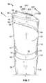
- FIG. 1is an isometric view of one embodiment of an actuator overcap
- FIG. 2is a front elevational view of the overcap of FIG. 1 ;
- FIG. 3is a rear elevational view of the overcap of FIG. 1 ;
- FIG. 4is a right side elevational view of the overcap of FIG. 1 ;
- FIG. 5is a left side elevational view of the overcap of FIG. 1 ;
- FIG. 6is a top plan view of the overcap of FIG. 1 ;
- FIG. 7is an isometric view of the overcap of FIG. 1 mounted on a fluid container
- FIG. 8is an exploded isometric view of the overcap of FIG. 1 ;
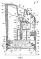
- FIG. 9is an enlarged partial sectional view taken generally along the lines 9 - 9 of FIG. 7 ;
- FIG. 10is an isometric view of the overcap of FIG. 1 with a portion of a housing removed;
- FIG. 11is a top plan view of the overcap of FIG. 10 ;
- FIG. 12is a side elevational view of the overcap of FIG. 10 ;
- FIG. 13is another embodiment of an overcap similar to the one depicted in FIG. 7 , which includes an A.C. power connector;
- FIG. 14is an isometric view of another embodiment of a dispensing system
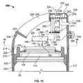
- FIG. 15is a partial sectional view taken generally along the lines 15 - 15 of FIG. 14 , with portions of the system behind the plane of section removed for purposes of clarity;
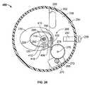
- FIG. 16is a sectional view taken generally along the lines 16 - 16 of FIG. 15 ;
- FIG. 17is a side elevational view of yet another embodiment of an overcap, which is similar to the one shown in FIG. 12 except for a change to a drive unit and a displacement member;
- FIG. 18is a top plan view of the overcap of FIG. 17 ;
- FIG. 19is a partial sectional view of still another embodiment of a dispensing system taken generally along the lines 19 - 19 of FIG. 14 , which is similar to the system depicted in FIG. 15 except for a change to a drive unit and a displacement member;
- FIG. 20is a sectional view taken generally along the lines 20 - 20 of FIG. 19 ;
- FIG. 21is a timing diagram illustrating the operation of the overcap of FIGS. 1-12 according to a first operational sequence.
- FIG. 22is another embodiment of an overcap, which is similar to the one shown in FIG. 1 except for the addition of a sensor.
- FIGS. 1-6depict an actuator overcap 10 having a generally cylindrical housing 12 that has a longitudinal dimension along a longitudinal axis 14 and a radial dimension along a radial axis 16 .
- the housing 12includes a base portion 18 and a removable cap 20 .
- the base portion 18comprises a cylindrical section 22 adapted to be retained on an upper end 24 of a conventional aerosol container 26 , which is shown in FIG. 7 , and will be described in further detail below.
- a post 28extends upwardly from a top end 30 of the cylindrical section 22 .
- the post 28includes a curved distal end 32 with an oval pushbutton 34 on an outer wall thereof.
- the pushbutton 34is further provided with a concave depression 36 .
- a cylindrical rod 38(see FIG. 8 ) is provided on an inner wall 40 (see FIG. 9 ) of the post 28 generally opposite the pushbutton 34 .
- the removable cap 20includes a cylindrical bottom portion 42 , which has a diameter substantially equal to that of the top end 30 of the cylindrical section 22 .
- a sidewall 44extends between the bottom portion 42 of the removable cap 20 and a top portion 46 thereof.
- the sidewall 44tapers outwardly about the longitudinal axis 14 of the removable cap 20 so that a cross-sectional diameter of the removable cap adjacent the bottom portion 42 is smaller than a cross-sectional diameter of the removable cap 20 adjacent the top portion 46 .
- the uniform tapering of the removable cap 20is truncated by a stepped portion 48 .
- the stepped portion 48includes first and second tapered surfaces 50 , 52 , respectively, that extend inwardly toward the longitudinal axis 14 of the removable cap 20 .
- the first and second tapered surfaces 50 , 52include first ends 54 , 56 , respectively, disposed on opposing sides of a groove 58 adjacent the bottom portion 42 of the removable cap 20 .
- the tapered surfaces 50 , 52curve upwardly from the first ends 54 , 56 toward a portion 60 of the removable cap 20 opposite the groove 58 and adjacent the top portion 46 .
- An upper surface 62 of the removable cap 20is convex and is bounded by a circular peripheral edge 64 .
- An elliptical shaped discharge orifice 66is centrally disposed within the upper surface 62 .
- a frusto-conical wall 68depends downwardly into an interior of the removable cap 20 about a periphery of the discharge orifice 66 .
- a curved groove 70is disposed between the discharge orifice 66 and the peripheral edge 64 .
- the groove 70includes a flat bottom 72 with a rectangular notch 74 disposed therein.
- An aperture 76is also provided between the groove 70 and the peripheral edge 64 .
- a light transmissive rod 78is held within the aperture 76 by an interference fit.
- the base portion 18includes a platform 80 that is disposed on the top end 30 of the cylindrical section 22 .
- the platform 80is sized to frictionally engage with the bottom portion 42 of the removable cap 20 when the removable cap is attached to the base portion 18 .
- FIG. 9illustrates that the platform 80 comprises an inwardly stepped portion, which includes a sidewall 82 and a top portion 84 .
- the sidewall 82includes a circumferential notch 86 adapted to fittingly receive an annular portion 88 on an inner wall 90 of the removable cap 20 adjacent the bottom portion 42 thereof.
- additional retention supportis provided by the groove 58 , which is sized to fittingly receive the post 28 when the removable cap 20 is placed on the base portion 18 .
- the useraligns the groove 58 with the post 28 and slides the removable cap 20 downwardly until same contacts the top end 30 of the base portion 18 and forms an interference fit with the platform 80 .
- a bottom end 92 of the base portion 18is also shaped to fit on the upper end 24 of the aerosol container 26 .
- FIG. 9shows that the present embodiment includes recesses 94 , 96 around an inner circumference 98 of the base portion 18 .
- the recess 94is defined by a surface 100 and the recess 96 is defined by a surface 102 , which includes an annular portion 104 that projects inwardly therefrom.
- a distal end 106 of the annular portion 104forms a snap fit with an undercut 108 of a mounting cup 110 .
- the surface 100forms an interference fit with portions of the aerosol container 26 beneath the mounting cup 110 .
- the snap fit between the annular portion 104 and the undercut 108 and the interference fit between the surface 100 and portions of the aerosol container 26assist in securely mounting the base portion 18 to the aerosol container 26 . Further, contact between the bottom end 92 of the base portion 18 and the upper end 24 of the aerosol container 26 may assist in preventing rocking or shifting of the base portion 18 when mounted on the aerosol container 26 .
- the removable cap 20 and the base portion 18form an integral unit that is attached to the upper end 24 of the aerosol container 26 by an interference fit.
- the housing 12may be retained on the aerosol container 26 in any manner known by those skilled in the art.
- the overcap 10discharges fluid from the aerosol container 26 upon the occurrence of a particular condition.
- the conditioncould be the manual activation of the overcap 10 or the automatic activation of the overcap 10 in response to an electrical signal from a timer or a sensor.
- the fluid dischargedmay be a fragrance or insecticide disposed within a carrier liquid, a deodorizing liquid, or the like.
- the fluidmay also comprise other actives, such as sanitizers, air fresheners, odor eliminators, mold or mildew inhibitors, insect repellents, and/or the like, and/or that have aromatherapeutic properties.
- the fluidalternatively comprises any fluid known to those skilled in the art that may be dispensed from a container.
- the overcap 10is therefore adapted to dispense any number of different fluid formulations.
- the container 26may be an aerosol container of any size and volume known to those skilled in the art.
- the container 26preferably comprises a body 112 (see FIG. 7 ) with the mounting cup 110 crimped to the upper end 24 thereof.
- the mounting cup 110is generally cylindrical in shape and includes an outer wall 114 that extends circumferentially therearound (see FIG. 9 ).
- a pedestal 116extends upwardly from the mounting cup 110 .
- a valve assembly (not shown) within the container 26includes a valve stem 118 extending upwardly from the pedestal 116 .
- a bore 120extends from the valve assembly through the valve stem 118 .
- the valve stem 118is of the tilt-activated type similar to the one described in Van der Heijden U.S. Pat. No. 4,064,782, which is herein incorporated by reference in its entirety.
- a radial displacementincludes any displacement of the discharge end 122 of the valve stem 118 away from the longitudinal axis 14 .
- Such a radial displacementmay therefore be characterized as a lateral or a transverse displacement of the discharge end 122 of the valve stem 118 .
- the contents of the container 26may be discharged in a continuous or metered dose. Further, the discharging of the contents of the container 26 may be effected in any number of ways, e.g., a discharge may comprise a partial metered dose or multiple consecutive discharges.
- a first transverse wall 124is provided with first and second frame members 126 , 128 on opposing sides thereof. The first and second frame members 126 , 128 are attached to the top portion 84 of the platform 80 .
- a second transverse wall 130is provided with third and fourth frame members 132 , 134 that extend from opposing sides thereof and that are similarly attached to the top portion 84 of the platform 80 .
- a horizontal platform 136spans the first and second transverse walls 124 , 130 and includes an aperture 138 (see FIG. 9 ) disposed therethrough.
- Third and fourth transverse walls 140 , 142are also provided to add rigidity to the structure of the base 18 .
- the first and second frame members 126 , 128are adapted to retain a D.C. power source 144 comprising one or more AA or AAA batteries therein.
- the power source 144 of the present embodimentis shown schematically to illustrate the interchangeability of the batteries with other power sources.
- the batteriesmay be replaced by a rechargeable Nickel-Cadmium battery pack having an electrical lead 146 that may be used to connect the battery pack to an A.C. power outlet 148 , such as seen in FIG. 13 .
- the D.C. power source 144may be entirely replaced by an A.C. power adapter having an appropriate power transformer and A.C./D.C. converter as known to those of skill in the art.
- a control circuit(not shown) is etched on a printed circuit board 150 .
- the control circuitallows for the electrical activation of a drive unit 152 disposed within the housing 12 (see FIGS. 9 , 11 , and 12 ).
- the drive unit 152includes a main drive gear 154 that is mounted on a rotatable drive shaft 156 of an electric motor 158 .
- the main drive gear 154is in mechanical association with a first transfer gear 160 that is fixedly mounted on a first transfer shaft 162 .
- a smaller second transfer gear 164is also fixedly mounted on the first transfer shaft 162 .
- the first transfer shaft 162is rotatably mounted to the platform 136 .
- a third transfer geare.g., a butterfly gear 166
- the butterfly gear 166is fixedly mounted on a second transfer shaft 168 that is similarly mounted to the platform 136 in a rotatable manner.
- a cam or camming membersuch as an actuating cam 170 shown in FIGS. 9 , 11 , and 12 , is provided on the butterfly gear 166 .
- the actuating cam 170includes a lateral surface 172 having a generally arcuate shape (see FIGS. 6 and 11 ).
- a displacement member 174is shown in cross-section in FIG. 9 .
- the displacement member 174includes an opening 176 at a first end or attachment end 178 thereof.
- the attachment end 178is press fit or otherwise attached to the valve stem 118 in a manner that allows the opening 176 to be in fluid communication with the bore 120 of the valve stem 118 .
- the attachment end 178is fashioned in a manner to provide for a substantially fluid tight seal between an outer portion of the valve stem 118 and the displacement member 174 .
- An aperture 180is provided adjacent a second end or distal end 182 of the displacement member 174 , which is in fluid communication with the opening 176 by a conduit 184 .
- a dispensing nozzle 186is provided at the distal end 182 of the displacement member 174 .
- the dispensing nozzle 186includes a discharge conduit 188 having an outwardly tapering cross-section in fluid communication with the aperture 180 .
- the dispensing nozzle 186also includes a contoured outer surface 190 that is wider than other portions of the displacement member 174 , which is adapted to be impinged laterally by the surface 172 of the actuating cam 170 .
- the outer surface 190includes a different shape, a different size, or is removed altogether, insofar as the displacement member 174 may be impinged by the actuating cam 170 .
- the discharge conduit 188 of the dispensing nozzle 186is modified to have a different shape, e.g., the walls defining the discharge conduit 188 could taper inwardly, could be provided with protrusions, or could be coextensive with the conduit 184 .
- the conduit 184is modified to have a different shape and/or to have a varying cross-sectional shape.
- the actuating cam 170is shown to be disposed adjacent the dispensing nozzle 186 .
- the lateral surface 172 of the actuating cam 170is positioned out of contact with the outer surface 190 of the dispensing nozzle 186 or in contact to a degree insufficient to radially tilt the dispensing member 174 to actuate the valve stem 118 .
- the motor 158is activated to transfer power through the main drive gear 154 , the first and second transfer gears 160 , 164 , the butterfly gear 166 , and through the actuating cam 170 .
- a quarter turn of the actuating cam 170results in the surface 172 of the actuating cam 170 impinging against the outer surface 190 of the displacement member 174 and displacing same radially.
- this level of displacementis sufficient to radially tilt the valve stem 118 a sufficient degree to open the valve assembly within the container 26 .
- the first and second transfer gears 160 , 164 , the butterfly gear 166 , and the actuating cam 170are sized to allow for precise control of the rotational displacement of the actuating cam 170 .
- One skilled in the artwill know how to modify the above-noted structure to effect a full or partial radial translation of the displacement member 174 and/or the valve stem 118 during an operational sequence.
- FIGS. 8-10 and 12depict a normally open switch 192 disposed on the second transverse wall 130 that is in electrical communication with the printed circuit board 150 .
- the switch 192is operably aligned with the pushbutton 34 such that the manual depression of the pushbutton 34 closes the open switch 192 . Closing the switch 192 causes the activation of the electric motor 158 in a similar manner as discussed above.
- a user selectable switch assembly 194is disposed adjacent a top portion of the printed circuit board 150 .
- the user selectable switch assembly 194 of the present embodimentis a linear displacement type switch having a control member, e.g., a finger 196 , extending upwardly therefrom.
- the finger 196may be used to select different operating modes (as discussed in greater detail below).
- the finger 196fits within the notch 74 when the removable cap 20 is engaged with the base portion 18 such that a user may operatively interact with the finger 196 (see FIG. 1 ).
- the user selectable switch assembly 194may be rotational and controlled by a turning knob, or could have any other geometric configuration and corresponding control mechanism as is known in the art.
- a light emitting diode (LED) 198is disposed on the printed circuit board 150 adjacent the light transmissive rod 78 of the removable cap 20 (see FIG. 9 ).
- FIGS. 14-16depict a different embodiment of a dispensing system 200 , which comprises a housing 202 having a base 204 and a removable top 206 .
- the base 202includes a lower end 208 and an upper end 210 .
- a sidewall 212 having a varying cross-sectional diameterextends between the lower and upper ends 208 , 210 , so that a medial portion 214 of the sidewall has a smaller cross-section than the lower and upper ends 208 , 210 .
- the container 26is retained within the base 204 of the housing 202 in a substantially immovable manner.
- a plurality of annular protrusions 216snap-fittingly engage with the undercut 108 of the mounting cup 110 of the aerosol container 26 .
- the container 26may be retained within the housing 202 in any manner known to those skilled in the art and/or discussed herein, e.g., a bottom end of the container 26 could be held within a fitted circular recess in the lower end 208 of the base 204 or the container 26 could be held by an interference fit between interior portions of the housing 202 and portions of the container 26 .
- the removable top 206is adapted to be removably disposed on the upper end 210 of the base 204 .
- a bottom edge 218 of the removable top 206includes an inwardly extending annular protrusion 220 that snap fits into a corresponding annular groove 222 disposed within the upper end 210 of the base 204 . Removal of the removable top 206 exposes an interior of the housing 202 and allows a user to insert the container 26 therein.
- the removable top 206includes an upper surface 224 having a generally convex shape that is bounded by a curved peripheral edge 226 . An elliptical shaped discharge orifice 228 is disposed within the upper surface 224 .
- a frusto-conical wall 230depends downwardly into an interior of the housing 202 about a periphery of the discharge orifice 228 .
- a rectangular notch 232is disposed between the discharge orifice 228 and the peripheral edge 226 .
- a finger 234extends upwardly through the rectangular notch 232 from a user selectable switch assembly 236 mounted to a platform 238 disposed within the interior of the housing 202 .
- An aperture 240is also provided between the rectangular notch 232 and the peripheral edge 226 .
- An LED 242is disposed on the platform 238 and extends upwardly through the aperture 240 .
- a sensor 250is provided on a bottom side of the platform 238 .
- a sensing portion of the sensor 250is exposed to the environment through an opening 252 in the removable top 206 beneath the peripheral edge 226 thereof.
- the platform 238extends between the frusto-conical wall 230 and a sidewall 254 of the removable top 206 .
- a printed circuit board(not shown) is affixed to the platform 238 and is in electrical communication with the switch assembly 236 , the LED 242 , and the sensor 250 .
- a power source 256(see FIG. 16 ), similar to the power source 144 described above, is also provided adjacent the platform 238 .
- a spring-loaded pushbutton 258is provided within an orifice 260 of the sidewall 254 beneath the sensor 250 .
- the pushbutton 258is operably aligned with a normally open switch 262 , which is adapted to be closed upon manual depression of the pushbutton 258 by a user.
- a control circuit(not shown) is etched on the printed circuit board.
- the control circuitallows for the electrical activation of a drive unit 266 disposed within the housing 202 (see FIGS. 15 and 16 ).
- the drive unit 266is similar to the drive unit disclosed above in connection with FIGS. 9 , 11 , and 12 .
- the drive unit 266includes a main drive gear 268 fixedly mounted to a rotatable shaft 270 of an electric motor 272 .
- the main drive gear 268is in mechanical association with a first transfer gear 274 that is fixedly mounted to a first transfer shaft 276 .
- a smaller second transfer gear 278is also fixedly mounted on the first transfer shaft 276 .
- the first transfer shaft 276is rotatably mounted to the platform 238 .
- a third transfer gear 280is in mechanical association with the second transfer gear 278 .
- the third transfer gear 280is fixedly mounted on a second transfer shaft 282 that is similarly mounted to the platform 238 in a rotatable manner.
- An actuating cam 284is also fixedly mounted on the second transfer shaft 282 .
- Activation of the drive unit 266causes a transfer of power from the electric motor 272 , through the gear assembly ( 268 , 278 , 280 ), and to the actuating cam 284 .
- the actuating cam 284is disposed adjacent a displacement member 286 , which may be similar in operation and structure as the displacement member 174 discussed above, to radially actuate the displacement member 286 and the valve stem 118 in response to an activation signal.
- FIGS. 15 and 16depict the displacement member 286 of the present embodiment with greater particularity.
- the displacement member 2136comprises a stepped cylindrical member, wherein a lower portion 288 includes a cross-section smaller than that of an upper portion 290 .
- the lower portion 288includes an opening 292 for receipt of a distal end of the valve stem 118 in a similar manner as noted above.
- An aperture 294is provided within the upper portion 290 of the displacement member 286 , which is in fluid communication with the opening 292 by a conduit 296 .
- An outer surface 298 of the upper portion 290is disposed adjacent the actuating cam 284 .
- FIGS. 17 and 18depict another embodiment of an overcap 300 similar to the one depicted in FIGS. 8-12 , which includes the drive unit 152 and the displacement member 174 .
- the electric motor 158is mounted to the platform 80 in a manner that provides for a longitudinal axis 302 of the motor 158 to be substantially transverse to a longitudinal axis 304 of the displacement member 174 .
- the first and second transfer shafts 162 , 168 of the present embodimentare mounted to the circuit board 150 in a substantially transverse manner with respect to the longitudinal axis 304 of the displacement member 174 .
- the present embodimentis therefore illustrative of the various manners in which the elements of the drive unit 152 may be oriented to effect a lateral or radial displacement of the displacement member 174 and, consequently, the valve stem 118 .
- any of the one or more elements of the drive unit 152i.e., the motor 158 , the gears 154 , 160 , 164 , 166 , or the shafts 156 , 162 , 168 , may be oriented in any position or angle radially about the longitudinal axis 302 of the displacement member 174 or a longitudinal axis of the valve stem 118 , insofar as radial displacement of the displacement member 174 and the valve stem 118 may be effected.
- the drive unit 152may comprise a set of transfer gears that are contained within a gear assembly having an input side driven by the motor 158 and an output side having an actuating cam attached thereto.
- the present embodimentalso includes an actuating cam 306 , which is different than the actuating cam 170 of FIGS. 8-12 .
- the actuating cam 306comprises a base member 308 fixedly mounted to the second transfer shaft 168 .
- a cam extension 310is disposed on the base member 308 in a manner that is off-centered from the second transfer shaft 168 and a center of the third transfer gear 166 .
- the third transfer gear 166 of the present embodimentis larger than the second transfer gear 164 .
- the cam extension 310may be disposed directly on the third gear 166 in an off-centered manner.
- the cam extension 310 of the present embodimentis generally cylindrical in shape, however, it is contemplated that other embodiments may use variously shaped or sized camming surfaces.
- the displacement member 174 of the present embodimentshas also been modified with respect to the displacement member 174 shown in FIGS. 8-12 .
- FIGS. 17 and 18show that the dispensing nozzle 186 has been removed from the distal end 182 of the displacement member 174 .
- the displacement member 174comprises a substantially uniformly cylindrical section 312 , wherein the aperture 180 discharges the fluid into the atmosphere and/or through the overcap 300 .
- a rectangular flange 314extends substantially transversely from the section 312 with respect to the longitudinal axis 302 of the displacement member 174 . It is also anticipated that the flange 314 may extend radially in any other manner with respect to the longitudinal axis 302 and that the flange 314 may comprise any other shape.
- the cam extension 310In a non-actuation position, the cam extension 310 is positioned out of contact with the flange 314 or in contact to a degree insufficient to radially tilt the dispensing member 174 to actuate the valve stem 118
- the motor 158is activated to transfer power to the cam extension 310 in a similar manner as discussed above.
- rotation of the third gear 166causes the cam extension to similarly rotate and impinge against a length of the flange 314 . Impingement of the flange 314 will cause the displacement member 174 attached thereto to rotate and be radially displaced. Sufficient radial displacement of the displacement member 174 will cause the valve stem 118 to rotate, the valve assembly within the container 26 to open, and for fluid to be dispensed from the overcap 300 .
- a half turn of the third gear 166 and the cam extension 310is sufficient to open the valve assembly of the container 26 .
- the drive unit 152 and the displacement member 174may be modified to effect a dispensing of fluid based on a greater or lesser rotation of any of the above noted elements.
- FIGS. 19 and 20depict yet another embodiment of a dispensing system 400 similar to the one shown in FIGS. 14-16 .
- the second transfer gear 278is spaced from the first transfer gear 274 on the first transfer shaft 276 .
- the third transfer gear 280is fixedly mounted to a shaft 402 that extends generally transversely from a distal end 404 of a connector 406 .
- the connector 406is attached to the platform 238 .
- the electric motor 272 , the main drive gear 268 , and the first through third transfer gears 274 , 278 , 280are all in mechanical communication to cause the rotation of an actuating cam 408 , which is provided in a similar manner as the actuating cam of FIGS. 17 and 18 .
- the actuating cam 408includes a base member 410 fixedly mounted to the shaft 402 .
- a cam extension 412is disposed on the base member 410 in a manner that is off-centered from the shaft 402 and a center of the third transfer gear 280 .
- the displacement member 286 depicted in FIGS. 15 and 16has also been modified for purposes of the present embodiment.
- the present embodiment of the displacement member 286comprises a substantially uniformly cylindrical portion 414 , wherein the aperture 294 is disposed on an upper end 416 of the displacement member 286 in fluid communication with the opening 292 by the conduit 296 .
- a rectangular flange 418extends substantially transversely from the cylindrical portion 414 with respect to a longitudinal axis 420 of the displacement member 286 .
- the cam extension 412In a non-actuation position, the cam extension 412 is positioned out of contact with the flange 418 or in contact to a degree insufficient to radially tilt the dispensing member 286 to actuate the valve stem 118 .
- valve stem 118actuates with each corresponding radial displacement.
- the valve stem 118is radially displaced to a discharge position for a predetermined length of time (“spraying period”).
- the duration of the spraying periodis typically equal to about 170 milliseconds.
- the valve stem 118could be radially displaced to the discharge position until all of the container contents are exhausted.
- the valve stem 118may be radially displaced during each of multiple spraying periods in response to the occurrence of a single activation signal, wherein the spraying periods are separated by rest periods. Multiple spraying periods may be beneficial when a single extended spraying period from a container is undesirable or when intermittent discharge is desired.
- FIG. 21depicts a timing diagram illustrative of an operational sequence of the overcap 10 during an in use condition.
- the overcap 10is energized by moving the finger 196 from an “OFF” position to one of four operating modes 500 , 502 , 504 , 506 , whereupon the overcap 10 enters a startup delay period.
- Each of the four operating modes 500 , 502 , 504 , 506corresponds to a predetermined sleep period between consecutive spraying periods.
- the first operating mode 500may correspond to a five minute sleep period
- the second operating mode 502may correspond to a seven and a half minute sleep period
- the third operating mode 504may correspond to a fifteen minute sleep period
- the fourth operating mode 506may correspond to a thirty minute sleep period.
- the first operating mode 500has been chosen.
- the drive unit 152is energized to discharge fluid from the overcap 10 during a first spraying period.
- the startup delay periodis preferably about three seconds long, and the spraying period is typically about 170 milliseconds long.
- the overcap 10enters a first sleep period that lasts 5 minutes.
- the drive unit 152Upon expiration of the first sleep period the drive unit 152 is energized to discharge fluid during a second spraying period. Thereafter, the overcap 10 enters a second sleep period that lasts for 5 minutes.
- the second sleep periodis interrupted by the manual activation of the overcap 10 , whereupon fluid is dispensed during a third spraying period. Automatic operation thereafter continues with alternating sleep and spraying periods.
- the usermay manually actuate the overcap 10 for a selectable or fixed period of time by depressing the pushbutton 34 .
- the overcap 10completes the pending sleep period. Thereafter, a spraying operation is undertaken.
- the switch assembly 194may have a continuous range of settings instead of the four distinct operating modes 500 , 502 , 504 , 506 described above.
- the switch assembly 194may be provided with a switch mechanism, for example a dial (not shown), that provides for continuous user variation of the spraying period and/or the sleep period between a continuous spray and periods lasting several hours or days.
- the switch assembly 194may be replaced and/or supplemented by the sensor 250 , e.g., a photocell motion sensor. The photocell collects ambient light and allows the control circuit to detect any changes in the intensity thereof. Filtering of the photocell output is undertaken by the control circuit.
- the control circuitdetermines that a threshold light condition has been reached, e.g., a predetermined level of change in light intensity, the control circuit develops a signal to energize the drive unit 152 .
- a threshold light conditione.g., a predetermined level of change in light intensity
- the control circuitdevelops a signal to energize the drive unit 152 .
- a threshold light conditione.g., a predetermined level of change in light intensity
- the control circuitdevelops a signal to energize the drive unit 152 .
- a threshold light conditione.g., a predetermined level of change in light intensity
- the LED 198illuminates the light transmissive rod 78 when the overcap 10 is in an operative state.
- the LED 198blinks intermittently once every fifteen seconds during the sleep period.
- the blinking frequency of the LED 198begins to increase as a spraying period becomes imminent.
- the more frequent illumination of the LED 198serves as a visual indication that the overcap 10 is about to discharge fluid contents into the atmosphere.
- the switch assembly 194may be replaced or supplemented with a vibration sensor, an odor sensor, a heat sensor, or any other environmental sensor known to those skilled in the art.
- more than one environmental sensormay be provided in the overcap in lieu of the switch assembly 194 or in combination with same. It is anticipated that one skilled in the art may provide any type of environmental sensor either alone or in combination with the switch assembly 194 and/or other sensors to meet the needs of a user.
- the switch assembly 194 and the environmental sensor 250are provided in the same overcap.
- a usermay choose to use the timer-based switch assembly 194 to automatically operate the drive unit 152 of the overcap, or the user may choose to use the environmental sensor 250 to detect a given event prior to activating the overcap.
- the overcapmay operate in a timer and sensor based mode of operation concurrently.
- any of the embodiments described hereinmay be modified to include any of the structures or methodologies disclosed in connection with different embodiments. Further, the present disclosure is not limited to aerosol containers of the type specifically shown. Still further, the overcaps of any of the embodiments disclosed herein may be modified to work with any type of aerosol or non-aerosol container having a tilt-activated valve stem.
- Aerosol dispensersare commonly used to dispense volatile materials such as air fresheners, deodorants, insecticides, germicides, decongestants, perfumes, and the like, that are stored within aerosol containers.
- Automated valve activation systems for aerosol containersallow the contents thereof to be released without human interaction, for example, according to a predetermined time schedule.
- Tilt-activated valve stems for aerosol container release valvestypically require less force to operate than vertically activated valve stems.
- a system for activation of a tilt-activated valve stemthat includes a drive unit that is controlled by a timing circuit and/or a sensor is presented. The system may be installed in a typical overcap for use with ordinary tilt-activated containers, resulting in an improvement in utility of the aerosol dispenser.
Landscapes
- Health & Medical Sciences (AREA)
- Chemical & Material Sciences (AREA)
- Mechanical Engineering (AREA)
- Engineering & Computer Science (AREA)
- Dispersion Chemistry (AREA)
- Animal Behavior & Ethology (AREA)
- Veterinary Medicine (AREA)
- Public Health (AREA)
- General Health & Medical Sciences (AREA)
- Life Sciences & Earth Sciences (AREA)
- Epidemiology (AREA)
- Containers And Packaging Bodies Having A Special Means To Remove Contents (AREA)
- Nozzles (AREA)
- Closures For Containers (AREA)
Abstract
Description
Claims (5)
Priority Applications (12)
| Application Number | Priority Date | Filing Date | Title |
|---|---|---|---|
| US11/893,476US8469244B2 (en) | 2007-08-16 | 2007-08-16 | Overcap and system for spraying a fluid |
| EP08795268AEP2178570A1 (en) | 2007-08-16 | 2008-08-13 | Overcap and system for spraying a fluid |
| CN201410103181.0ACN103832698A (en) | 2007-08-16 | 2008-08-13 | Overcap and system for spraying a fluid |
| PCT/US2008/009663WO2009025741A1 (en) | 2007-08-16 | 2008-08-13 | Overcap and system for spraying a fluid |
| CA2696044ACA2696044A1 (en) | 2007-08-16 | 2008-08-13 | Overcap and system for spraying a fluid |
| JP2010521017AJP5364094B2 (en) | 2007-08-16 | 2008-08-13 | Overcap and system for spraying fluid |
| BRPI0815185-7A2ABRPI0815185A2 (en) | 2007-08-16 | 2008-08-13 | OVERFLOW AND SYSTEM FOR SPRINKLING A FLUID |
| AU2008289530AAU2008289530B2 (en) | 2007-08-16 | 2008-08-13 | Overcap and system for spraying a fluid |
| KR1020107004142AKR20100054137A (en) | 2007-08-16 | 2008-08-13 | Overcap and system for spraying a fluid |
| CN200880111511ACN101820925A (en) | 2007-08-16 | 2008-08-13 | Top cap and system for spraying fluid |
| ARP080103574AAR067955A1 (en) | 2007-08-16 | 2008-08-15 | COVER AND SYSTEM TO ATOMIZE A FLUID |
| US13/906,152US20130277389A1 (en) | 2007-08-16 | 2013-05-30 | Overcap and system for spraying a fluid |
Applications Claiming Priority (1)
| Application Number | Priority Date | Filing Date | Title |
|---|---|---|---|
| US11/893,476US8469244B2 (en) | 2007-08-16 | 2007-08-16 | Overcap and system for spraying a fluid |
Related Child Applications (1)
| Application Number | Title | Priority Date | Filing Date |
|---|---|---|---|
| US13/906,152ContinuationUS20130277389A1 (en) | 2007-08-16 | 2013-05-30 | Overcap and system for spraying a fluid |
Publications (2)
| Publication Number | Publication Date |
|---|---|
| US20090045219A1 US20090045219A1 (en) | 2009-02-19 |
| US8469244B2true US8469244B2 (en) | 2013-06-25 |
Family
ID=40091900
Family Applications (2)
| Application Number | Title | Priority Date | Filing Date |
|---|---|---|---|
| US11/893,476Active2028-12-30US8469244B2 (en) | 2007-08-16 | 2007-08-16 | Overcap and system for spraying a fluid |
| US13/906,152AbandonedUS20130277389A1 (en) | 2007-08-16 | 2013-05-30 | Overcap and system for spraying a fluid |
Family Applications After (1)
| Application Number | Title | Priority Date | Filing Date |
|---|---|---|---|
| US13/906,152AbandonedUS20130277389A1 (en) | 2007-08-16 | 2013-05-30 | Overcap and system for spraying a fluid |
Country Status (10)
| Country | Link |
|---|---|
| US (2) | US8469244B2 (en) |
| EP (1) | EP2178570A1 (en) |
| JP (1) | JP5364094B2 (en) |
| KR (1) | KR20100054137A (en) |
| CN (2) | CN103832698A (en) |
| AR (1) | AR067955A1 (en) |
| AU (1) | AU2008289530B2 (en) |
| BR (1) | BRPI0815185A2 (en) |
| CA (1) | CA2696044A1 (en) |
| WO (1) | WO2009025741A1 (en) |
Cited By (14)
| Publication number | Priority date | Publication date | Assignee | Title |
|---|---|---|---|---|
| US8622259B2 (en)* | 2012-04-09 | 2014-01-07 | Hsu-Hui Chang | Electrical valve control device |
| US10420444B2 (en) | 2015-12-30 | 2019-09-24 | Gpcp Ip Holdings Llc | Hands-free flowable material dispensers and related methods |
| USD896946S1 (en)* | 2018-05-24 | 2020-09-22 | Zobele Holding Spa | Diffusing evaporator of active substances |
| US11636870B2 (en) | 2020-08-20 | 2023-04-25 | Denso International America, Inc. | Smoking cessation systems and methods |
| US11760169B2 (en) | 2020-08-20 | 2023-09-19 | Denso International America, Inc. | Particulate control systems and methods for olfaction sensors |
| US11760170B2 (en) | 2020-08-20 | 2023-09-19 | Denso International America, Inc. | Olfaction sensor preservation systems and methods |
| US11813926B2 (en) | 2020-08-20 | 2023-11-14 | Denso International America, Inc. | Binding agent and olfaction sensor |
| US11828210B2 (en) | 2020-08-20 | 2023-11-28 | Denso International America, Inc. | Diagnostic systems and methods of vehicles using olfaction |
| US11881093B2 (en) | 2020-08-20 | 2024-01-23 | Denso International America, Inc. | Systems and methods for identifying smoking in vehicles |
| US11932080B2 (en) | 2020-08-20 | 2024-03-19 | Denso International America, Inc. | Diagnostic and recirculation control systems and methods |
| US12017506B2 (en) | 2020-08-20 | 2024-06-25 | Denso International America, Inc. | Passenger cabin air control systems and methods |
| US12251991B2 (en) | 2020-08-20 | 2025-03-18 | Denso International America, Inc. | Humidity control for olfaction sensors |
| US12269315B2 (en) | 2020-08-20 | 2025-04-08 | Denso International America, Inc. | Systems and methods for measuring and managing odor brought into rental vehicles |
| US12377711B2 (en) | 2020-08-20 | 2025-08-05 | Denso International America, Inc. | Vehicle feature control systems and methods based on smoking |
Families Citing this family (18)
| Publication number | Priority date | Publication date | Assignee | Title |
|---|---|---|---|---|
| US8387827B2 (en)* | 2008-03-24 | 2013-03-05 | S.C. Johnson & Son, Inc. | Volatile material dispenser |
| US9527656B2 (en)* | 2009-07-31 | 2016-12-27 | Seaquistperfect Dispensing L.L.C. | Touchless dispenser |
| EP2384995B1 (en)* | 2010-05-06 | 2014-10-15 | Dreumex B.V. | Aerosol container and dispenser machine |
| US8464905B2 (en) | 2010-10-29 | 2013-06-18 | S.C. Johnson & Son, Inc. | Dispensers and functional operation and timing control improvements for dispensers |
| USD668150S1 (en) | 2010-11-09 | 2012-10-02 | S.C. Johnson & Son, Inc. | Container with retaining device |
| FR2978364B1 (en)* | 2011-07-25 | 2013-08-23 | Valois Sas | HEAD OF DISTRIBUTION OF FLUID PRODUCT |
| WO2013043684A2 (en) | 2011-09-19 | 2013-03-28 | S. C. Johnson & Son, Inc. | Spray dispenser |
| US9247724B2 (en)* | 2012-09-07 | 2016-02-02 | S.C. Johnson & Son, Inc. | Product dispensing system |
| US9108782B2 (en) | 2012-10-15 | 2015-08-18 | S.C. Johnson & Son, Inc. | Dispensing systems with improved sensing capabilities |
| EP3322539A1 (en)* | 2015-07-15 | 2018-05-23 | Gary Rayner | Systems and methods for producing a foamable and/or flowable material for consumption |
| CN110711732A (en)* | 2018-07-13 | 2020-01-21 | 苏州宝时得电动工具有限公司 | Hand-held pressure cleaning machine |
| USD907173S1 (en)* | 2019-01-25 | 2021-01-05 | Kyu Dai Cho | Portable hydrogen water mist sprayer |
| CN109701050A (en)* | 2019-03-13 | 2019-05-03 | 李晓惠 | A kind of UV sterilizing feeding bottle device |
| WO2020205054A1 (en) | 2019-04-03 | 2020-10-08 | Suterra, Llc | Puffer device |
| GB2595692B (en)* | 2020-06-03 | 2024-10-23 | Senzer Ltd | A refill for an inhaler particularly a cannabinoid inhaler |
| JP7656188B2 (en)* | 2021-06-23 | 2025-04-03 | 日亜化学工業株式会社 | Semiconductor laser device |
| WO2025088195A1 (en)* | 2023-10-25 | 2025-05-01 | L'oreal | Actuating device for an atomizer of an odorous solution |
| FR3154633A1 (en)* | 2023-10-25 | 2025-05-02 | L'oreal | Actuating device for vaporizer of an odorous solution |
Citations (296)
| Publication number | Priority date | Publication date | Assignee | Title |
|---|---|---|---|---|
| US2608319A (en) | 1948-01-15 | 1952-08-26 | Stanton H Petry | Gas discharge device for gas bombs |
| US2613108A (en) | 1949-04-01 | 1952-10-07 | George F Kraus | Fluid dispenser |
| US2928573A (en) | 1958-02-25 | 1960-03-15 | Syncro Mist Controls Inc | Valve actuating assembly for metered spray atomizing devices |
| US3018056A (en) | 1960-09-29 | 1962-01-23 | Montgomery Mfg Company Inc | Timed spray dispensers |
| US3115277A (en) | 1963-01-22 | 1963-12-24 | Jr Charles A Montague | Pressure can device |
| US3127060A (en) | 1964-03-31 | Automatic actuator for spray containers | ||
| US3139218A (en)* | 1962-05-16 | 1964-06-30 | Richardson Merrell Inc | Dispensing apparatus for portable pressurized containers |
| US3165238A (en) | 1962-02-19 | 1965-01-12 | Heuer Timer Corp | Intermittent actuating device for dispensers |
| US3180532A (en) | 1964-06-18 | 1965-04-27 | Clayton Corp Of Delaware | Tamper-proof cover for a container |
| US3185356A (en) | 1962-03-27 | 1965-05-25 | Risdon Mfg Co | Metering valve |
| US3199732A (en) | 1963-03-20 | 1965-08-10 | Robertshaw Controls Co | Spray timer |
| US3228609A (en) | 1964-05-26 | 1966-01-11 | Syncro Mist Controls Inc | Spray dispenser |
| US3240389A (en) | 1964-12-24 | 1966-03-15 | Robertshaw Controls Co | Spray timer |
| GB1033025A (en) | 1962-02-19 | 1966-06-15 | Heuer Timer Corp | Intermittent valve-actuating device for portable pressurised aerosol dispensers |
| US3269602A (en) | 1964-09-24 | 1966-08-30 | Time Mist Inc | Periodically operated aerosol dispenser |
| US3273610A (en) | 1966-09-20 | Valved pressurized fluid dispensing receptaclewith receptacle-attached fitting | ||
| US3289886A (en) | 1964-02-24 | 1966-12-06 | Goldsholl Morton | Timing device and method |
| US3305134A (en) | 1965-10-21 | 1967-02-21 | Union Carbide Corp | Automatic spray device |
| US3326418A (en) | 1966-01-21 | 1967-06-20 | Willis A Kropp | Dispensing device |
| US3329314A (en) | 1965-08-20 | 1967-07-04 | Gen Time Corp | Timed actuating device for aerosol dispenser |
| US3368717A (en) | 1965-10-24 | 1968-02-13 | Time Mist Inc | Dispenser |
| US3398864A (en) | 1966-06-24 | 1968-08-27 | Gen Time Corp | Adapter apparatus for automatic aerosol dispenser |
| US3411670A (en) | 1967-09-11 | 1968-11-19 | Edward L Brown | Automatic dispenser for pressurized liquid |
| US3419189A (en) | 1967-08-21 | 1968-12-31 | Iketani Taisho | Device for automatically and intermittently spraying pressurized products |
| US3455485A (en) | 1967-03-20 | 1969-07-15 | Lawrence T Crownover | Automatic cycling mechanism |
| US3477613A (en) | 1968-02-29 | 1969-11-11 | Dart Ind Inc | Aerosol dispenser actuated by propellant pressure |
| US3497108A (en) | 1967-10-26 | 1970-02-24 | Dart Ind Inc | Automatic dispenser |
| US3497110A (en) | 1968-04-12 | 1970-02-24 | Eversharp Inc | Aerosol dispenser |
| US3542248A (en) | 1969-01-08 | 1970-11-24 | John J Mangel | Aerosol dispenser controlled by permanent magnet |
| US3543122A (en) | 1968-01-02 | 1970-11-24 | Air Guard Control Canada Ltd | Automatic aerosol dispenser |
| US3584766A (en) | 1969-12-10 | 1971-06-15 | Charles M Hart | Spray dispenser having a capacitor discharge timer |
| US3589563A (en) | 1969-08-11 | 1971-06-29 | Gen Time Corp | Long period battery-operated aerosol dispenser |
| US3589562A (en) | 1969-02-10 | 1971-06-29 | Buck Willard | Pressure-powered aerosol timer |
| US3591058A (en) | 1968-11-05 | 1971-07-06 | Republic Corp | Tapping device for beer kegs and the like |
| US3617214A (en) | 1969-08-18 | 1971-11-02 | Raymond E Dolac | Door-operated air freshener |
| US3620023A (en) | 1969-07-25 | 1971-11-16 | Howard C Schmid | Pulsating valves |
| US3627176A (en) | 1969-09-24 | 1971-12-14 | William M Sailors | Automatic spray dispenser for pressurized fluid |
| US3632020A (en) | 1970-12-17 | 1972-01-04 | Virginia Chemicals Inc | Dispenser for aerosol bombs |
| US3643836A (en) | 1969-12-18 | 1972-02-22 | William Grayson Hunt | Programmed timer device and dispensing apparatus incorporating same |
| US3658209A (en) | 1970-10-29 | 1972-04-25 | Gen Time Corp | Automatic cycling discharging device |
| US3664548A (en) | 1969-07-10 | 1972-05-23 | Inst For Ind Res & Standards | Aerosol containers and valves thereof |
| US3666144A (en) | 1970-12-11 | 1972-05-30 | Air Guard Control Canada Ltd | Aerosol dispensing apparatus having disc-shaped solenoid-actuated plunger |
| US3677441A (en) | 1970-09-10 | 1972-07-18 | Virginia Chemicals Inc | Multiple aerosol dispenser |
| US3690519A (en) | 1969-01-24 | 1972-09-12 | Victor Wassilieff | Closures for containers |
| US3722749A (en) | 1970-12-31 | 1973-03-27 | M Ishida | Aerosol spray container |
| US3726437A (en) | 1971-01-21 | 1973-04-10 | N Siegel | Aerosol spray dispenser |
| US3732509A (en) | 1971-01-18 | 1973-05-08 | Syncro Mist Controls Inc | Apparatus to provide periodic movement |
| US3739944A (en) | 1972-05-25 | 1973-06-19 | Westinghouse Electric Corp | Automatic periodically actuated spray dispenser |
| US3756465A (en) | 1971-01-06 | 1973-09-04 | P Meshberg | Automatic periodic dispenser |
| US3794216A (en) | 1973-02-22 | 1974-02-26 | Spray A Matic Prod Inc | Pressure powered aerosol timer |
| US3817429A (en) | 1971-02-24 | 1974-06-18 | T Smrt | Actuator for aerosol can valve |
| US3841525A (en)* | 1972-06-14 | 1974-10-15 | N Siegel | Aerosol spray device with cam activator |
| US3870274A (en) | 1972-06-30 | 1975-03-11 | Chr Nielsens Eftf As | Motor driven valve |
| US3871557A (en) | 1973-08-02 | 1975-03-18 | Smrt Thomas John | Spraying apparatus |
| US3885712A (en) | 1974-06-28 | 1975-05-27 | Sidney M Libit | Childproof closures of the pull-push type |
| US3929259A (en) | 1974-06-04 | 1975-12-30 | Charles R Fegley | Chemical dispensing anti-burglar device |
| US3952916A (en) | 1975-01-06 | 1976-04-27 | Warner-Lambert Company | Automatic dispenser for periodically actuating an aerosol container |
| US3968905A (en) | 1975-08-07 | 1976-07-13 | Continental Can Company, Inc. | Time release aerosol dispenser |
| US3974941A (en) | 1974-12-16 | 1976-08-17 | Mettler Leo L | Automated aerosol mist dispenser |
| US3980205A (en) | 1975-03-20 | 1976-09-14 | Qantas Airways Limited | Aerosol can discharging apparatus |
| US4004550A (en) | 1973-11-29 | 1977-01-25 | White Ronald D | Apparatus for preparing microscope slides |
| US4006844A (en) | 1975-04-10 | 1977-02-08 | The Risdon Manufacturing Company | Apparatus for operating an aerosol container |
| US4063664A (en) | 1976-09-13 | 1977-12-20 | The Risdon Manufacturing Company | Device for indicating when automatic, periodic operation has emptied an aerosol container |
| US4064573A (en) | 1975-07-02 | 1977-12-27 | Cahill, Sutton & Thomas | Cleanser-sanitizer and timed cycle deodorizing spray attachment for toilets |
| US4068780A (en) | 1976-06-03 | 1978-01-17 | Fegley Charles R | Electrothermally actuated fluid dispensing device |
| US4068575A (en) | 1976-08-24 | 1978-01-17 | Whirlpool Corporation | Refuse compactor with selective spray device |
| US4077542A (en) | 1974-12-02 | 1978-03-07 | Petterson Tor H | Unattended aerosol dispenser |
| US4096974A (en) | 1977-03-11 | 1978-06-27 | Haber Terry M | Cover assembly for spray cans |
| GB1531308A (en) | 1976-11-22 | 1978-11-08 | Johnson & Son Inc S C | Dispensing receptacle for aerosol container |
| US4184612A (en) | 1977-03-30 | 1980-01-22 | Freyre Leopoldo E | Automatic sprayer |
| US4235373A (en) | 1976-10-12 | 1980-11-25 | Strattwell Developments Limited | Fluid dispenser |
| US4238055A (en) | 1978-04-26 | 1980-12-09 | Staar S.A. | Powered atomizer |
| US4275821A (en) | 1979-09-17 | 1981-06-30 | Lanno Joseph P | Drive system and fluid dispenser unit utilizing same |
| US4396152A (en) | 1977-03-02 | 1983-08-02 | Abplanalp Robert H | Aerosol dispenser system |
| US4415797A (en) | 1980-04-19 | 1983-11-15 | Nikitas Choustoulakis | Apparatus for dispensing a material into the atmosphere |
| US4483466A (en) | 1981-02-26 | 1984-11-20 | Gutierrez Arturo M | Apparatus for automatically operating the discharge valve of a pressure container |
| US4544086A (en) | 1982-11-19 | 1985-10-01 | Cook International, Inc. | Ornament including automatic and adjustable valving mechanism |
| US4658985A (en) | 1983-12-09 | 1987-04-21 | Clean-Tex A/S | Method of dispensing vapor to the air in a room and an apparatus for carrying out the method |
| US4702418A (en)* | 1985-09-09 | 1987-10-27 | Piezo Electric Products, Inc. | Aerosol dispenser |
| US4877989A (en) | 1986-08-11 | 1989-10-31 | Siemens Aktiengesellschaft | Ultrasonic pocket atomizer |
| US4967935A (en) | 1989-05-15 | 1990-11-06 | Celest Salvatore A | Electronically controlled fluid dispenser |
| US4989755A (en) | 1988-12-20 | 1991-02-05 | Shiau Guey Chuan | Automatic cleaning-liquid dispensing device |
| US4993570A (en) | 1989-11-13 | 1991-02-19 | Sunbeam Plastics Corporation | Tamper indicating container-closure package |
| US5012961A (en) | 1983-12-09 | 1991-05-07 | Milliken Research Corporation | Method of dispensing vapor to the air in a room and an apparatus for carrying out the method |
| US5014881A (en) | 1987-08-28 | 1991-05-14 | Raimund Andris | Metering and spray pump for liquid and low-viscosity substances |
| US5018963A (en) | 1989-08-07 | 1991-05-28 | Tpv Energy System, Inc. | Pulsating gas powered light source |
| US5025962A (en) | 1990-01-12 | 1991-06-25 | Robert J. Leblanc | Automatic timed release spray dispenser |
| US5029729A (en) | 1983-12-09 | 1991-07-09 | Milliken Denmark A/S | Method of dispensing vapor to the air in a room and an apparatus for carrying out the method |
| US5038972A (en) | 1989-09-26 | 1991-08-13 | Technical Concepts, Inc. | Metered aerosol fragrance dispensing mechanism |
| US5055822A (en) | 1990-07-06 | 1991-10-08 | Gordon Campbell | Scent alarm device |
| US5098291A (en) | 1989-04-14 | 1992-03-24 | Colgate-Palmolive Company | Pressurized medicant applicator |
| US5134961A (en) | 1990-09-10 | 1992-08-04 | The Regents Of The University Of California | Electrically actuated variable flow control system |
| US5154323A (en) | 1991-01-22 | 1992-10-13 | Query Grady W | Aerosol applicator and actuator |
| US5198157A (en) | 1990-08-20 | 1993-03-30 | Dynamad S. A. R. L. | Ultrasonic device for the continuous production of particles |
| US5221025A (en) | 1989-05-31 | 1993-06-22 | Conceptair Anstalt | Method and mechanical, electrical, or electronic apparatus for dispensing, issuing, or diffusing medicines, fragrances or other liquid or visous substances in the liquid phase or in the gaseous phase |
| US5249718A (en) | 1992-03-16 | 1993-10-05 | Technical Concepts | Automatic pump-type spray dispenser |
| US5297988A (en) | 1990-11-02 | 1994-03-29 | Nippondenso Co., Ltd. | Fragrance supplying apparatus for vehicle |
| US5337929A (en) | 1989-07-20 | 1994-08-16 | Airspray International B.V. | Mixing chamber for mixing a gaseous and a liquid component |
| US5337926A (en) | 1992-02-07 | 1994-08-16 | The Procter & Gamble Company | Spray pump package employing multiple orifices for dispensing liquid in different spray patterns with automatically adjusted optimized pump stroke for each pattern |
| US5342584A (en) | 1989-09-13 | 1994-08-30 | Ecolab Inc. | Air freshener device and cartridge with battery |
| US5353744A (en) | 1991-05-14 | 1994-10-11 | Dogwatch, Inc. | Animal control apparatus |
| US5364028A (en) | 1994-03-03 | 1994-11-15 | Wozniak Walter E | Pneumatic timed spray dispenser |
| US5383580A (en) | 1993-04-05 | 1995-01-24 | Winder; Gary C. | Aerosol spray can adaptor |
| US5392768A (en) | 1991-03-05 | 1995-02-28 | Aradigm | Method and apparatus for releasing a controlled amount of aerosol medication over a selectable time interval |
| US5397028A (en) | 1992-04-29 | 1995-03-14 | Jesadanont; Mongkol | Automatic fluid dispenser and method |
| US5445324A (en) | 1993-01-27 | 1995-08-29 | The United States Of America As Represented By The United States Department Of Energy | Pressurized feed-injection spray-forming apparatus |
| US5447277A (en) | 1992-07-17 | 1995-09-05 | Neumag-Neumuensterische Maschinen Und Anlagenbau Gmbh | Method of winding yarn on a bobbin or the like in a stepwise high precision winding process |
| US5449117A (en) | 1993-10-04 | 1995-09-12 | Technical Concepts, L.P. | Apparatus and method for controllably dispensing drops of liquid |
| US5503303A (en) | 1994-10-14 | 1996-04-02 | S. C. Johnson & Son, Inc. | Dual function self-pressurized aerosol actuator overcap |
| US5522722A (en) | 1994-11-10 | 1996-06-04 | Thermo Power Corporation | Fuel control |
| US5531344A (en) | 1994-11-14 | 1996-07-02 | Winner International Royalty Corporation | Actuator for a personal protective spray canister |
| US5540359A (en) | 1995-10-16 | 1996-07-30 | Gobbel; Keith | Sprayer extension deivce |
| US5542605A (en) | 1994-04-07 | 1996-08-06 | Flow-Rite Controls, Ltd. | Automatic liquid dispenser |
| US5549228A (en) | 1995-08-11 | 1996-08-27 | Insta-Foam Products, Inc. | Attachment system for fluent product dispensers |
| US5588565A (en) | 1994-02-14 | 1996-12-31 | Miller; Sidney H. | Valve for dispensing pressurized fluid through a flexible tube |
| US5601235A (en) | 1993-12-04 | 1997-02-11 | United Kingdom Atomic Energy Authority | Aerosol generator |
| US5622162A (en) | 1991-03-05 | 1997-04-22 | Aradigm Corporation | Method and apparatus for releasing a controlled amount of aerosol medication over a selectable time interval |
| US5673825A (en) | 1995-11-29 | 1997-10-07 | Bobson Hygiene International Inc. | Holder for holding a deodorant bottle therein |
| US5676283A (en) | 1996-07-04 | 1997-10-14 | Kae Chuang International Co., Ltd. | Power device for a perfume sprayer |
| US5685456A (en) | 1995-05-24 | 1997-11-11 | The United States Of America As Represented By The Secretary Of The Navy | Regulated dispensing system |
| US5695091A (en) | 1995-10-25 | 1997-12-09 | The Path-X Corporation | Automated dispenser for disinfectant with proximity sensor |
| US5702036A (en) | 1995-09-07 | 1997-12-30 | Precision Valve Corporation | Aerosol total release actuator having a delay in product emission |
| EP0826607A1 (en) | 1996-08-23 | 1998-03-04 | W.L. GORE & ASSOCIATES GmbH | Closure for drinking container |
| US5743251A (en) | 1996-05-15 | 1998-04-28 | Philip Morris Incorporated | Aerosol and a method and apparatus for generating an aerosol |
| US5772074A (en) | 1995-03-31 | 1998-06-30 | Waterbury Companies, Inc. | Device and method for indicating the dispensing of a predetermined amount of a material |
| US5787947A (en) | 1996-11-19 | 1998-08-04 | Tetra Laval Holdings & Finance S.A. | Flexible nozzle integrated with a transformable wire |
| US5791524A (en) | 1997-05-12 | 1998-08-11 | S. C. Johnson & Son, Inc. | Total release actuator for an aerosol can |
| US5810265A (en) | 1994-09-07 | 1998-09-22 | Reckitt & Colman Products Limited | Electrostatic spraying device |
| US5823390A (en) | 1995-10-06 | 1998-10-20 | Technical Concepts, L.P. | Chemical dispensing apparatus having a pivotal actuator |
| US5842602A (en) | 1998-03-26 | 1998-12-01 | Pierpoint; James W. | Irritant dispenser and method |
| US5853129A (en) | 1997-03-25 | 1998-12-29 | Spitz; Albert W. | Spray nozzle |
| US5884808A (en) | 1997-08-21 | 1999-03-23 | Technical Concepts, L.P. | Material dispensing method and apparatus having display feature |
| US5908140A (en) | 1997-08-21 | 1999-06-01 | Technical Concepts, L.P. | Material dispensing method and apparatus with stall detect |
| US5922247A (en) | 1997-07-28 | 1999-07-13 | Green Clouds Ltd. | Ultrasonic device for atomizing liquids |
| US5924597A (en) | 1997-09-19 | 1999-07-20 | Lynn; David M. | Building fragrance distribution system and method |
| US5938076A (en) | 1994-04-25 | 1999-08-17 | Averyck Engineering Consultants B.V. | Dispenser for an aerosol can |
| US5964403A (en) | 1997-04-22 | 1999-10-12 | Board Of Trustees Operating Michigan State University | Automated electronically controlled microsprayer |
| US6000658A (en) | 1998-04-13 | 1999-12-14 | Mccall, Jr.; Tommie | Toilet paper dispenser |
| US6006957A (en) | 1998-03-06 | 1999-12-28 | S. C. Johnson & Son, Inc. | Actuator overcap for a pressurized canister |
| US6036108A (en) | 1998-07-23 | 2000-03-14 | Bobson Hygiene International Inc. | Automatic liquid spraying device |
| US6039212A (en) | 1998-02-20 | 2000-03-21 | Ccl Industries Inc. | Aerosol dispenser |
| US6089410A (en) | 1997-08-27 | 2000-07-18 | L'oreal | Pump-type packaging unit for a liquid or semi-liquid product |
| US6145712A (en) | 1998-01-23 | 2000-11-14 | L'oreal | Valve with outlet flow rate regulation, and container equipped with such a valve |
| US6182904B1 (en) | 1997-04-22 | 2001-02-06 | Board Of Trustees Operating Michigan State University | Automated electronically controlled microsprayer |
| JP2001048254A (en) | 1999-08-03 | 2001-02-20 | Toyo Aerosol Ind Co Ltd | Delay jet device for aerosol container |
| US6216925B1 (en) | 1999-06-04 | 2001-04-17 | Multi-Vet Ltd. | Automatic aerosol dispenser |
| US6220293B1 (en) | 1997-05-05 | 2001-04-24 | Ardishir Rashidi | Multiple outlets self-actuated irrigation valve |
| US6237812B1 (en) | 1999-10-12 | 2001-05-29 | Eiko-Sha Co. Ltd. | Aerosol dispensing system |
| US6249717B1 (en) | 1996-11-08 | 2001-06-19 | Sangstat Medical Corporation | Liquid medication dispenser apparatus |
| US6254065B1 (en) | 1997-07-11 | 2001-07-03 | Cws International Ag | Evaporation dispenser having a control timer for timed release of a volatile substance from an evaporation chamber |
| US6260739B1 (en) | 1999-02-23 | 2001-07-17 | Chung J. Hsiao | Self-contained hose assembly for a pressurized canister |
| US6267297B1 (en) | 1999-10-12 | 2001-07-31 | Waterbury Companies, Inc. | Programmable dispenser |
| US6276574B1 (en) | 1999-11-10 | 2001-08-21 | Thomas J. Smrt | Apparatus and method for selectively dispensing aerosolized water from a container |
| US6293474B1 (en) | 1999-03-08 | 2001-09-25 | S. C. Johnson & Son, Inc. | Delivery system for dispensing volatiles |
| US6293442B1 (en) | 2000-05-16 | 2001-09-25 | Girard D. Mollayan | Timed aerosol spray dispenser |
| US6321742B1 (en) | 1996-08-12 | 2001-11-27 | The Coleman Company, Inc. | Pressurized fluid container |
| US6338424B2 (en) | 1998-12-21 | 2002-01-15 | Kao Corporation | Aerosol container |
| US6343714B1 (en) | 1999-06-11 | 2002-02-05 | Electro Spray Inc. | Anti-graffiti aerosol spray can having an internal spray head valve control assembly |
| US20020020756A1 (en) | 1997-12-25 | 2002-02-21 | Gotit Ltd. | Automatic spray dispenser |
| JP2002068344A (en) | 2000-08-31 | 2002-03-08 | Toyo Aerosol Ind Co Ltd | Continuous spray apparatus |
| EP0826608B1 (en) | 1996-08-28 | 2002-04-03 | Kyowa Industrial Co., Ltd. | Spray mechanism for an aerosol product |
| JP2002113398A (en) | 2000-10-05 | 2002-04-16 | Yasushi Kobayashi | Automatic spray device for aerosol can |
| US6394310B1 (en) | 1999-09-15 | 2002-05-28 | Kenneth J. Muderlak | System and method for programmably dispensing material |
| EP1214949A2 (en) | 2000-12-06 | 2002-06-19 | Dudley Industries Ltd. | Dispensing device |
| US6419122B1 (en) | 1998-04-29 | 2002-07-16 | Peter Arthur Charles Chown | Magnetically operated apparatus for dispensing a chemical |
| US20020130146A1 (en) | 2001-03-14 | 2002-09-19 | Borut Severine N. | Automatic air freshener with dynamically variable dispensing interval |
| US6454185B2 (en) | 2000-02-12 | 2002-09-24 | Ing. Erich Pfeiffer Gmbh | Discharge apparatus for media |
| US6478199B1 (en) | 2002-01-24 | 2002-11-12 | S. C. Johnson & Son, Inc. | Automatic valve |
| US6510561B1 (en) | 1998-10-21 | 2003-01-28 | Reckitt Benckiser (Uk) Limited | Dispensing device |
| US6533141B1 (en) | 2001-10-31 | 2003-03-18 | S. C. Johnson & Son, Inc. | Intermittent aerosol dispensing valve |
| US6554203B2 (en) | 2000-08-30 | 2003-04-29 | Ing. Erich Pfeiffer Gmbh | Smart miniature fragrance dispensing device for multiple ambient scenting applications and environments |
| WO2003037748A1 (en) | 2001-10-31 | 2003-05-08 | S. C. Johnson & Son, Inc. | Automatic intermittent aerosol dispensing valve |
| US20030089734A1 (en) | 2000-06-10 | 2003-05-15 | Heiko Eberhardt | Container |
| US6567613B2 (en) | 1999-09-24 | 2003-05-20 | Reckitt Benckiser (Uk) Limited | Electrical device for evaporating a volatile liquid |
| WO2003042068A1 (en) | 2001-11-13 | 2003-05-22 | S. C. Johnson & Son, Inc. | Aerosol dispensing valve |
| EP1316514A2 (en) | 2001-11-29 | 2003-06-04 | Guillermo Luis Giangreco | Automatic actuator for aerosol valves |
| WO2003062094A1 (en) | 2002-01-24 | 2003-07-31 | S. C. Johnson & Son, Inc. | Intermittent aerosol dispensing valve |
| JP2003246380A (en) | 2002-02-22 | 2003-09-02 | Kyowa Industrial Co Ltd | Aerosol can and its cap |
| US6616363B1 (en) | 1999-03-19 | 2003-09-09 | Reckitt Benckiser France | Container for dispensing a heated fluid |
| US6619562B2 (en) | 2000-06-16 | 2003-09-16 | Omron Corporaton | Ultrasonic atomizer allowing states of operation to be readily distinguished |
| WO2003082709A1 (en) | 2002-03-27 | 2003-10-09 | Rentokil Initial Uk Limited | A device for actuating the valve of an aerosol container |
| JP2003311191A (en) | 2002-04-18 | 2003-11-05 | Daizo:Kk | Aerosol system |
| US6645307B2 (en) | 1999-12-22 | 2003-11-11 | Reckitt Benckiser (Uk) Limited | Photocatalytic compositions and methods |
| US6669105B2 (en) | 2000-09-13 | 2003-12-30 | Adapco, Inc. | Closed-loop mosquito insecticide delivery system and method |
| US20040011885A1 (en) | 2000-11-17 | 2004-01-22 | Mclisky Nigel Haig | Dispensing means |
| US20040028551A1 (en) | 2000-07-27 | 2004-02-12 | Kvietok Frank Andrej | Methods for emitting volatile compositions |
| US20040033171A1 (en) | 2000-07-27 | 2004-02-19 | The Procter & Gamble Company | Systems and devices for emitting volatile compositions |
| US6694536B1 (en) | 2002-08-14 | 2004-02-24 | Basil Haygreen | Fragrant water closet closer |
| US20040035949A1 (en) | 2002-08-12 | 2004-02-26 | Coastal Mosquito Control Llc | Insect control system and method |
| US6701663B1 (en) | 1998-12-24 | 2004-03-09 | Reckitt Benckiser (Uk) Limited | Method and apparatus for dispersing a volatile composition |
| US6708849B1 (en) | 2002-03-18 | 2004-03-23 | Precision Thermoplastic Components, Inc. | Actuator and tube overcap assembly |
| USD488548S1 (en) | 2002-11-23 | 2004-04-13 | Reckitt Benckiser (Uk) Limited | Air freshener device |
| US6722529B2 (en) | 2002-04-15 | 2004-04-20 | Michael J. Ceppaluni | Air flow scent enhancer |
| US20040074935A1 (en) | 2002-10-10 | 2004-04-22 | Chon Khor Kim | Olfactory stimulating material dispensing apparatus |
| US6739479B2 (en) | 2002-04-09 | 2004-05-25 | Waterbury Companies, Inc. | Dispensing system |
| US20040155056A1 (en) | 2000-01-25 | 2004-08-12 | Gotit Ltd. | Spray dispenser |
| US6776968B2 (en) | 2000-02-29 | 2004-08-17 | Reckitt Benckiser (Uk) Limited | Diffuser |
| US6785911B1 (en) | 2003-11-13 | 2004-09-07 | Marvin J. Percher | Automatic actuator for aerosol containers |
| US6790408B2 (en) | 1999-07-17 | 2004-09-14 | Reckitt Benckiser (Uk) Limited | Fragrance emitting device |
| JP2004298782A (en) | 2003-03-31 | 2004-10-28 | Seiko Clock Inc | Spray equipment |
| US20040219863A1 (en) | 2001-05-22 | 2004-11-04 | Willacy Geoffrey Valentine | Method and apparatus for distributing treatment agents |
| US6832701B2 (en) | 2002-04-05 | 2004-12-21 | Johnsondiversey, Inc. | Self metering dispensing device |
| US20050004714A1 (en) | 2003-07-02 | 2005-01-06 | Cheng-Fong Chen | Deodorizer control device for spraying system |
| US6843465B1 (en) | 2003-08-14 | 2005-01-18 | Loren W. Scott | Memory wire actuated control valve |
| US20050023287A1 (en) | 2003-02-18 | 2005-02-03 | Frank Speckhart | Method of discharging an aerosolized fluid |
| WO2005014060A1 (en) | 2003-07-18 | 2005-02-17 | Reckitt Benckiser (Australia) Pty Limited | Portable device for vapour emanation by heating a volatile compound in a cartridge |
| JP2005081223A (en) | 2003-09-08 | 2005-03-31 | Suncreo Corp | Automatic spray apparatus of aerosol can |
| WO2005027630A1 (en) | 2003-09-19 | 2005-03-31 | Reckitt Benckiser (Uk) Limited | Device for dispensing volatile compounds in a gel to the ambient air |
| EP1522506A1 (en) | 2003-10-08 | 2005-04-13 | Xianyang Jin | Aerosol spray container with time delayed release actuator |
| US20050139624A1 (en) | 2003-02-18 | 2005-06-30 | Hooks Aaron L. | Method of discharging an aerosolized fluid |
| US6918512B2 (en) | 2002-06-24 | 2005-07-19 | Fukugo Shizai Co., Ltd. | Refillable spray container |
| US20050155985A1 (en) | 2002-07-01 | 2005-07-21 | Reckitt Benckiser Limited | Electrically heated vapour dispensing apparatus |
| WO2005070474A1 (en) | 2004-01-23 | 2005-08-04 | Reckitt Benckiser (Uk) Limited | Device for dispensing a fluid |
| US6926172B2 (en) | 2001-10-31 | 2005-08-09 | S. C. Johnson & Son, Inc. | Total release dispensing valve |
| US6926002B2 (en) | 1998-05-05 | 2005-08-09 | Trudell Medical International | Indicating device |
| WO2005079583A1 (en) | 2004-02-13 | 2005-09-01 | Reckitt Benckiser (Uk) Limited | Hotplate emanation |
| US6938796B2 (en) | 1998-01-16 | 2005-09-06 | 1263152 Ontario Inc. | Indicating device |
| WO2005084721A1 (en) | 2004-03-06 | 2005-09-15 | Reckitt Benckiser (Uk) Limited | Emanator device |
| US20050224596A1 (en) | 2003-07-08 | 2005-10-13 | Panopoulos Peter J | Machine that is an automatic pesticide, insecticide, repellant, poison, air freshener, disinfectant or other type of spray delivery system |
| US20050247735A1 (en)* | 2004-05-10 | 2005-11-10 | Muderlak Kenneth J | Apparatus and method for dispensing post-foaming gel soap |
| US20050252930A1 (en) | 2004-05-11 | 2005-11-17 | Contadini Carl D | Dispensing system, a dispenser and a source of material to be used therewith |
| US6971560B1 (en) | 2004-05-14 | 2005-12-06 | S. C. Johnson & Son, Inc. | Friction resistant time delay actuator assembly for aerosol containers |
| US6974091B2 (en) | 2000-11-17 | 2005-12-13 | Mclisky Nigel Haig | Dispensing means |
| US20050279853A1 (en) | 2001-11-20 | 2005-12-22 | Mcleisch Andrew | Refill for an air freshener or insecticide device |
| USD513433S1 (en) | 2004-01-13 | 2006-01-03 | Reckitt Benckiser France | Air freshener device |
| US20060011737A1 (en) | 2002-02-11 | 2006-01-19 | Sara Lee/De B.V. | Liquid spray head, apparatus comprising a liquid spray-head and container therefore |
| WO2006005962A1 (en) | 2004-07-15 | 2006-01-19 | Reckitt Benckiser (Uk) Limited | Apparatus and method of using the same |
| WO2006013321A1 (en) | 2004-08-04 | 2006-02-09 | Reckitt Benckiser Inc | Dispensing device |
| WO2006013322A1 (en) | 2004-08-04 | 2006-02-09 | Reckitt Benckiser Inc | Improved dispensing device |
| US7000853B2 (en) | 2000-01-26 | 2006-02-21 | Dl Technology, Llc | System and method for control of fluid dispense pump |
| US20060037532A1 (en) | 2004-08-23 | 2006-02-23 | Richard Eidson | Artificial tanning solution and other fluid application apparatus, system and method |
| US20060060615A1 (en) | 2002-06-11 | 2006-03-23 | Mclisky Nigel H | Dispenser |
| US20060076366A1 (en) | 2004-10-12 | 2006-04-13 | Furner Paul E | Compact spray device |
| US7028917B2 (en) | 2001-01-15 | 2006-04-18 | Reckitt Benckiser (Uk) Limited | Air freshening device |
| US20060083632A1 (en) | 2003-01-31 | 2006-04-20 | Reckitt Benckiser (Uk) Limited | Pump |
| US20060081661A1 (en) | 2004-10-18 | 2006-04-20 | L'oreal | Dispensing device for a cosmetic product |
| US7032782B1 (en) | 2002-01-11 | 2006-04-25 | Joseph S. Kanfer | Holder for aerosol dispenser |
| EP1328757B1 (en) | 2000-10-18 | 2006-05-03 | Reckitt Benckiser (UK) LIMITED | Candle comprising a container and a wick sustainer |
| USD520623S1 (en) | 2004-01-16 | 2006-05-09 | Reckitt Benckiser (Uk) Limited | Air freshener device |
| US7044337B1 (en) | 2004-10-29 | 2006-05-16 | Min-Lan Kou | Unclogging device having safety cap |
| WO2006051267A1 (en) | 2004-11-11 | 2006-05-18 | Reckitt Benckiser Inc | Air purifier device |
| WO2006054103A1 (en) | 2004-11-19 | 2006-05-26 | Reckitt Benckiser N.V. | Closure with dispersable composition |
| US7051455B2 (en) | 2002-01-30 | 2006-05-30 | Reckitt Benckiser (Uk) Limited | Chemical compositions and methods for absorbing water vapor and combating malodor within a cavity |
| WO2006056762A1 (en) | 2004-11-23 | 2006-06-01 | Reckitt Benckiser (Australia) Pty Limited | Vapour emanation device |
| US20060118658A1 (en) | 2002-08-29 | 2006-06-08 | Reckitt Benckiser Inc. Morris Corporate Center Iv | Overcap and actuator button for aerosol spray can |
| WO2006058433A1 (en) | 2004-12-03 | 2006-06-08 | Multi-Vet Ltd. | Fluid delivery system for dispensing an active substance in spray form |
| US20060124477A1 (en) | 2002-09-26 | 2006-06-15 | Reckitt Benckiser (Uk) Limited | Odour absorbing clothes cover |
| WO2006064187A1 (en) | 2004-12-17 | 2006-06-22 | Reckitt Benckiser (Uk) Limited | Dispenser comprising electromagnetic locking with a magnet and reed switch |
| US20060140901A1 (en) | 2002-11-09 | 2006-06-29 | Reckitt Benckiser (Uk) Limited | Articles |
| US20060151546A1 (en) | 2002-05-24 | 2006-07-13 | Mclisky Nigel H | Dispenser |
| WO2006074454A2 (en) | 2005-01-10 | 2006-07-13 | Hyso Technology Llc | Door handle sanitizer system and valve attachment apparatus |
| USD525693S1 (en) | 2004-02-25 | 2006-07-25 | Reckitt Benckiser (Uk) Limited | Air freshener refill |
| US20060175341A1 (en) | 2004-11-29 | 2006-08-10 | Alwin Manufacturing Co., Inc. | Automatic dispensers |
| US20060175426A1 (en) | 2002-11-08 | 2006-08-10 | Schramm Heather R | Dispensing of multiple volatile substances |
| US20060175357A1 (en) | 2001-03-29 | 2006-08-10 | Hammond Geoffrey R | Valve |
| WO2006087515A1 (en) | 2005-02-15 | 2006-08-24 | Reckitt Benckiser (Uk) Limited | Spray device |
| WO2006087514A1 (en) | 2005-02-15 | 2006-08-24 | Reckitt Benckiser (Uk) Limited | Holder for a spray container |
| USD527472S1 (en) | 2004-10-12 | 2006-08-29 | Reckitt Benckiser (Uk) Limited | Floating candle holder |
| US20060191955A1 (en) | 2003-09-09 | 2006-08-31 | Mclisky Nigel H | Spray dispenser activated by sensed light level |
| US20060196576A1 (en) | 2003-10-29 | 2006-09-07 | John Fleming | Insect control system and method |
| WO2006095131A1 (en) | 2005-03-11 | 2006-09-14 | Reckitt Benckiser (Uk) Limited | Emanation device comprising an air driver |
| EP1702512A1 (en) | 2005-03-17 | 2006-09-20 | Reckitt Benckiser (UK) Limited | Device |
| US20060210421A1 (en) | 2003-08-16 | 2006-09-21 | Reckitt Benckiser (Uk) Limited | Dispenser |
| US20060219740A1 (en) | 2005-04-05 | 2006-10-05 | Precision Valve Corporation | Automatic purging and easy dispensing aerosol valve system |
| EP1709980A1 (en) | 2005-04-05 | 2006-10-11 | Reckitt Benckiser (UK) LIMITED | Emanation device |
| US20060229232A1 (en) | 2005-03-29 | 2006-10-12 | Contadini Carl D | Precision release aerosol device |
| US20060243762A1 (en) | 2005-01-10 | 2006-11-02 | Hyso Technology Llc | Controllable door handle sanitizer system and method |
| US7141125B2 (en) | 2001-06-28 | 2006-11-28 | Reckitt Benckiser (Uk) Limited | Photocatalytic composition |
| USD532891S1 (en) | 2005-03-04 | 2006-11-28 | Reckitt Benckiser (Uk) Limited | Air freshener device |
| EP1726315A1 (en) | 2005-05-26 | 2006-11-29 | Faber S.p.A. | A device for the programmed and controlled dispensing of volatile substances for scenting the environment and/or chasing insects away |
| WO2006134353A1 (en) | 2005-06-16 | 2006-12-21 | Reckitt Benckiser (Australia) Pty Limited | Product and method for emanating vapour active substances |
| US20070012718A1 (en) | 2005-04-12 | 2007-01-18 | Schramm Heather R | Apparatus for and Method of Dispensing Active Materials |
| US7168631B2 (en) | 2000-10-23 | 2007-01-30 | Reckitt Benckiser (Uk) Limited | Emanator device |
| USD536059S1 (en) | 2005-07-15 | 2007-01-30 | Reckitt Benckiser Inc. | Dispensing device |
| USD536082S1 (en) | 2005-05-06 | 2007-01-30 | Reckitt Benckiser | Air freshener device |
| US7182227B2 (en) | 2001-04-27 | 2007-02-27 | Reckitt Bencklser (Uk) Limited | Aerosol delivery system |
| USD537914S1 (en) | 2005-07-15 | 2007-03-06 | Reckitt Benckiser Inc. | Dispensing device |
| US7192610B2 (en) | 2000-04-07 | 2007-03-20 | Reckitt Benckiser (Uk) Limited | Method of deactivating dust mite allergens |
| USD538915S1 (en) | 2005-09-22 | 2007-03-20 | Reckitt Benckiser (Uk) | Air freshener device |
| US20070062980A1 (en) | 2003-05-05 | 2007-03-22 | The Procter & Gamble Company | Sprayer actuator, sprayer, and method of making the same |
| US7195139B2 (en) | 2004-06-29 | 2007-03-27 | S.C. Johnson & Son, Inc. | Dispensing valve |
| US20070071933A1 (en) | 2003-10-24 | 2007-03-29 | Fabrizio Gavelli | Article and method |
| WO2007036724A1 (en) | 2005-09-28 | 2007-04-05 | Reckitt Benckiser (Uk) Limited | Device for emanating an active agent |
| USD540931S1 (en) | 2004-03-04 | 2007-04-17 | Reckitt Benckiser (Uk) Limited | Emanator device |
| US20070093558A1 (en) | 1999-09-07 | 2007-04-26 | Reckitt Benckiser (Uk) Limited, A Uk Corporation | Electrostatic aerosol compositions |
| WO2007045826A1 (en) | 2005-10-18 | 2007-04-26 | Reckitt Benckiser (Uk) Limited | Spraying device |
| WO2007045827A1 (en) | 2005-10-18 | 2007-04-26 | Reckitt Benckiser (Uk) Limited | Spraying device |
| WO2007045828A1 (en) | 2005-10-18 | 2007-04-26 | Reckitt Benckiser (Uk) Limited | Spraying device |
| WO2007045832A1 (en) | 2005-10-21 | 2007-04-26 | Reckitt Benckiser (Uk) Limited | Air freshener with lighting unit |
| US20070138326A1 (en) | 2005-12-20 | 2007-06-21 | Zhiyu Hu | Automatic microfluidic fragrance dispenser |
| US20070158359A1 (en) | 2005-12-08 | 2007-07-12 | Rodrian James A | Method and Apparatus for Controlling a Dispenser and Detecting a User |
| EP1382399B1 (en) | 1997-08-20 | 2007-07-18 | Fumakilla Limited | Method for repelling or eliminating harmful organism |
| US7249720B2 (en) | 2002-10-25 | 2007-07-31 | Coty S.A.S. | Spray device with combined drive and resilient pivoting head for a spray bottle |
| EP1702513B1 (en) | 2005-03-17 | 2008-07-23 | Reckitt Benckiser (UK) Limited | Device |
| EP1695720B1 (en) | 2005-02-28 | 2008-10-29 | Kennedy Hygiene Procucts Ltd | Air freshener for ceiling-mounting |
| EP1430958B1 (en) | 1999-02-09 | 2013-04-10 | S.C. Johnson & Son, Inc. | Piezoelectric spraying system for dispensing volatiles |
Family Cites Families (2)
| Publication number | Priority date | Publication date | Assignee | Title |
|---|---|---|---|---|
| CN1496935A (en)* | 2002-10-10 | 2004-05-19 | Spy销售公司 | Improved distributing device for olfactory pungent |
| JP4545567B2 (en)* | 2004-11-26 | 2010-09-15 | アース製薬株式会社 | Aerosol device |
- 2007
- 2007-08-16USUS11/893,476patent/US8469244B2/enactiveActive
- 2008
- 2008-08-13AUAU2008289530Apatent/AU2008289530B2/ennot_activeCeased
- 2008-08-13JPJP2010521017Apatent/JP5364094B2/enactiveActive
- 2008-08-13EPEP08795268Apatent/EP2178570A1/ennot_activeWithdrawn
- 2008-08-13BRBRPI0815185-7A2Apatent/BRPI0815185A2/ennot_activeIP Right Cessation
- 2008-08-13CACA2696044Apatent/CA2696044A1/ennot_activeAbandoned
- 2008-08-13CNCN201410103181.0Apatent/CN103832698A/enactivePending
- 2008-08-13CNCN200880111511Apatent/CN101820925A/enactivePending
- 2008-08-13KRKR1020107004142Apatent/KR20100054137A/ennot_activeWithdrawn
- 2008-08-13WOPCT/US2008/009663patent/WO2009025741A1/enactiveApplication Filing
- 2008-08-15ARARP080103574Apatent/AR067955A1/enunknown
- 2013
- 2013-05-30USUS13/906,152patent/US20130277389A1/ennot_activeAbandoned
Patent Citations (322)
| Publication number | Priority date | Publication date | Assignee | Title |
|---|---|---|---|---|
| US3127060A (en) | 1964-03-31 | Automatic actuator for spray containers | ||
| US3273610A (en) | 1966-09-20 | Valved pressurized fluid dispensing receptaclewith receptacle-attached fitting | ||
| US2608319A (en) | 1948-01-15 | 1952-08-26 | Stanton H Petry | Gas discharge device for gas bombs |
| US2613108A (en) | 1949-04-01 | 1952-10-07 | George F Kraus | Fluid dispenser |
| US2928573A (en) | 1958-02-25 | 1960-03-15 | Syncro Mist Controls Inc | Valve actuating assembly for metered spray atomizing devices |
| US3018056A (en) | 1960-09-29 | 1962-01-23 | Montgomery Mfg Company Inc | Timed spray dispensers |
| GB1033025A (en) | 1962-02-19 | 1966-06-15 | Heuer Timer Corp | Intermittent valve-actuating device for portable pressurised aerosol dispensers |
| US3165238A (en) | 1962-02-19 | 1965-01-12 | Heuer Timer Corp | Intermittent actuating device for dispensers |
| US3185356A (en) | 1962-03-27 | 1965-05-25 | Risdon Mfg Co | Metering valve |
| US3139218A (en)* | 1962-05-16 | 1964-06-30 | Richardson Merrell Inc | Dispensing apparatus for portable pressurized containers |
| US3115277A (en) | 1963-01-22 | 1963-12-24 | Jr Charles A Montague | Pressure can device |
| US3199732A (en) | 1963-03-20 | 1965-08-10 | Robertshaw Controls Co | Spray timer |
| US3289886A (en) | 1964-02-24 | 1966-12-06 | Goldsholl Morton | Timing device and method |
| US3228609A (en) | 1964-05-26 | 1966-01-11 | Syncro Mist Controls Inc | Spray dispenser |
| US3180532A (en) | 1964-06-18 | 1965-04-27 | Clayton Corp Of Delaware | Tamper-proof cover for a container |
| US3269602A (en) | 1964-09-24 | 1966-08-30 | Time Mist Inc | Periodically operated aerosol dispenser |
| US3240389A (en) | 1964-12-24 | 1966-03-15 | Robertshaw Controls Co | Spray timer |
| US3329314A (en) | 1965-08-20 | 1967-07-04 | Gen Time Corp | Timed actuating device for aerosol dispenser |
| FR1497250A (en) | 1965-10-21 | 1967-10-06 | Union Carbide Corp | Automatic spraying device |
| US3305134A (en) | 1965-10-21 | 1967-02-21 | Union Carbide Corp | Automatic spray device |
| US3368717A (en) | 1965-10-24 | 1968-02-13 | Time Mist Inc | Dispenser |
| US3326418A (en) | 1966-01-21 | 1967-06-20 | Willis A Kropp | Dispensing device |
| US3398864A (en) | 1966-06-24 | 1968-08-27 | Gen Time Corp | Adapter apparatus for automatic aerosol dispenser |
| US3455485A (en) | 1967-03-20 | 1969-07-15 | Lawrence T Crownover | Automatic cycling mechanism |
| US3419189A (en) | 1967-08-21 | 1968-12-31 | Iketani Taisho | Device for automatically and intermittently spraying pressurized products |
| US3411670A (en) | 1967-09-11 | 1968-11-19 | Edward L Brown | Automatic dispenser for pressurized liquid |
| US3497108A (en) | 1967-10-26 | 1970-02-24 | Dart Ind Inc | Automatic dispenser |
| US3543122A (en) | 1968-01-02 | 1970-11-24 | Air Guard Control Canada Ltd | Automatic aerosol dispenser |
| US3477613A (en) | 1968-02-29 | 1969-11-11 | Dart Ind Inc | Aerosol dispenser actuated by propellant pressure |
| US3497110A (en) | 1968-04-12 | 1970-02-24 | Eversharp Inc | Aerosol dispenser |
| US3591058A (en) | 1968-11-05 | 1971-07-06 | Republic Corp | Tapping device for beer kegs and the like |
| US3542248A (en) | 1969-01-08 | 1970-11-24 | John J Mangel | Aerosol dispenser controlled by permanent magnet |
| US3690519A (en) | 1969-01-24 | 1972-09-12 | Victor Wassilieff | Closures for containers |
| US3589562A (en) | 1969-02-10 | 1971-06-29 | Buck Willard | Pressure-powered aerosol timer |
| US3664548A (en) | 1969-07-10 | 1972-05-23 | Inst For Ind Res & Standards | Aerosol containers and valves thereof |
| US3620023A (en) | 1969-07-25 | 1971-11-16 | Howard C Schmid | Pulsating valves |
| US3589563A (en) | 1969-08-11 | 1971-06-29 | Gen Time Corp | Long period battery-operated aerosol dispenser |
| US3617214A (en) | 1969-08-18 | 1971-11-02 | Raymond E Dolac | Door-operated air freshener |
| US3627176A (en) | 1969-09-24 | 1971-12-14 | William M Sailors | Automatic spray dispenser for pressurized fluid |
| US3584766A (en) | 1969-12-10 | 1971-06-15 | Charles M Hart | Spray dispenser having a capacitor discharge timer |
| US3643836A (en) | 1969-12-18 | 1972-02-22 | William Grayson Hunt | Programmed timer device and dispensing apparatus incorporating same |
| US3677441A (en) | 1970-09-10 | 1972-07-18 | Virginia Chemicals Inc | Multiple aerosol dispenser |
| US3658209A (en) | 1970-10-29 | 1972-04-25 | Gen Time Corp | Automatic cycling discharging device |
| US3666144A (en) | 1970-12-11 | 1972-05-30 | Air Guard Control Canada Ltd | Aerosol dispensing apparatus having disc-shaped solenoid-actuated plunger |
| US3632020A (en) | 1970-12-17 | 1972-01-04 | Virginia Chemicals Inc | Dispenser for aerosol bombs |
| US3722749A (en) | 1970-12-31 | 1973-03-27 | M Ishida | Aerosol spray container |
| US3756465A (en) | 1971-01-06 | 1973-09-04 | P Meshberg | Automatic periodic dispenser |
| US3732509A (en) | 1971-01-18 | 1973-05-08 | Syncro Mist Controls Inc | Apparatus to provide periodic movement |
| US3726437A (en) | 1971-01-21 | 1973-04-10 | N Siegel | Aerosol spray dispenser |
| US3817429A (en) | 1971-02-24 | 1974-06-18 | T Smrt | Actuator for aerosol can valve |
| US3739944A (en) | 1972-05-25 | 1973-06-19 | Westinghouse Electric Corp | Automatic periodically actuated spray dispenser |
| US3841525A (en)* | 1972-06-14 | 1974-10-15 | N Siegel | Aerosol spray device with cam activator |
| US3870274A (en) | 1972-06-30 | 1975-03-11 | Chr Nielsens Eftf As | Motor driven valve |
| US3794216A (en) | 1973-02-22 | 1974-02-26 | Spray A Matic Prod Inc | Pressure powered aerosol timer |
| US3871557A (en) | 1973-08-02 | 1975-03-18 | Smrt Thomas John | Spraying apparatus |
| US4004550A (en) | 1973-11-29 | 1977-01-25 | White Ronald D | Apparatus for preparing microscope slides |
| US3929259A (en) | 1974-06-04 | 1975-12-30 | Charles R Fegley | Chemical dispensing anti-burglar device |
| US3885712A (en) | 1974-06-28 | 1975-05-27 | Sidney M Libit | Childproof closures of the pull-push type |
| US4077542A (en) | 1974-12-02 | 1978-03-07 | Petterson Tor H | Unattended aerosol dispenser |
| US3974941A (en) | 1974-12-16 | 1976-08-17 | Mettler Leo L | Automated aerosol mist dispenser |
| US3952916A (en) | 1975-01-06 | 1976-04-27 | Warner-Lambert Company | Automatic dispenser for periodically actuating an aerosol container |
| US3980205A (en) | 1975-03-20 | 1976-09-14 | Qantas Airways Limited | Aerosol can discharging apparatus |
| US4006844A (en) | 1975-04-10 | 1977-02-08 | The Risdon Manufacturing Company | Apparatus for operating an aerosol container |
| US4064573A (en) | 1975-07-02 | 1977-12-27 | Cahill, Sutton & Thomas | Cleanser-sanitizer and timed cycle deodorizing spray attachment for toilets |
| US3968905A (en) | 1975-08-07 | 1976-07-13 | Continental Can Company, Inc. | Time release aerosol dispenser |
| US4068780A (en) | 1976-06-03 | 1978-01-17 | Fegley Charles R | Electrothermally actuated fluid dispensing device |
| US4068575A (en) | 1976-08-24 | 1978-01-17 | Whirlpool Corporation | Refuse compactor with selective spray device |
| US4063664A (en) | 1976-09-13 | 1977-12-20 | The Risdon Manufacturing Company | Device for indicating when automatic, periodic operation has emptied an aerosol container |
| US4235373A (en) | 1976-10-12 | 1980-11-25 | Strattwell Developments Limited | Fluid dispenser |
| GB1531308A (en) | 1976-11-22 | 1978-11-08 | Johnson & Son Inc S C | Dispensing receptacle for aerosol container |
| US4396152A (en) | 1977-03-02 | 1983-08-02 | Abplanalp Robert H | Aerosol dispenser system |
| US4096974A (en) | 1977-03-11 | 1978-06-27 | Haber Terry M | Cover assembly for spray cans |
| US4184612A (en) | 1977-03-30 | 1980-01-22 | Freyre Leopoldo E | Automatic sprayer |
| US4238055A (en) | 1978-04-26 | 1980-12-09 | Staar S.A. | Powered atomizer |
| US4275821A (en) | 1979-09-17 | 1981-06-30 | Lanno Joseph P | Drive system and fluid dispenser unit utilizing same |
| US4415797A (en) | 1980-04-19 | 1983-11-15 | Nikitas Choustoulakis | Apparatus for dispensing a material into the atmosphere |
| US4483466A (en) | 1981-02-26 | 1984-11-20 | Gutierrez Arturo M | Apparatus for automatically operating the discharge valve of a pressure container |
| US4544086A (en) | 1982-11-19 | 1985-10-01 | Cook International, Inc. | Ornament including automatic and adjustable valving mechanism |
| US4658985A (en) | 1983-12-09 | 1987-04-21 | Clean-Tex A/S | Method of dispensing vapor to the air in a room and an apparatus for carrying out the method |
| US4658985B1 (en) | 1983-12-09 | 1989-05-09 | ||
| US5012961A (en) | 1983-12-09 | 1991-05-07 | Milliken Research Corporation | Method of dispensing vapor to the air in a room and an apparatus for carrying out the method |
| US5029729A (en) | 1983-12-09 | 1991-07-09 | Milliken Denmark A/S | Method of dispensing vapor to the air in a room and an apparatus for carrying out the method |
| US4702418A (en)* | 1985-09-09 | 1987-10-27 | Piezo Electric Products, Inc. | Aerosol dispenser |
| US4877989A (en) | 1986-08-11 | 1989-10-31 | Siemens Aktiengesellschaft | Ultrasonic pocket atomizer |
| US5014881A (en) | 1987-08-28 | 1991-05-14 | Raimund Andris | Metering and spray pump for liquid and low-viscosity substances |
| US4989755A (en) | 1988-12-20 | 1991-02-05 | Shiau Guey Chuan | Automatic cleaning-liquid dispensing device |
| US5098291A (en) | 1989-04-14 | 1992-03-24 | Colgate-Palmolive Company | Pressurized medicant applicator |
| US4967935A (en) | 1989-05-15 | 1990-11-06 | Celest Salvatore A | Electronically controlled fluid dispenser |
| US5221025A (en) | 1989-05-31 | 1993-06-22 | Conceptair Anstalt | Method and mechanical, electrical, or electronic apparatus for dispensing, issuing, or diffusing medicines, fragrances or other liquid or visous substances in the liquid phase or in the gaseous phase |
| US5337929A (en) | 1989-07-20 | 1994-08-16 | Airspray International B.V. | Mixing chamber for mixing a gaseous and a liquid component |
| US5018963A (en) | 1989-08-07 | 1991-05-28 | Tpv Energy System, Inc. | Pulsating gas powered light source |
| US5342584A (en) | 1989-09-13 | 1994-08-30 | Ecolab Inc. | Air freshener device and cartridge with battery |
| US5038972A (en) | 1989-09-26 | 1991-08-13 | Technical Concepts, Inc. | Metered aerosol fragrance dispensing mechanism |
| USRE34847E (en) | 1989-09-26 | 1995-02-07 | Technical Concepts, Inc. | Metered aerosol fragrance dispensing mechanism |
| US4993570A (en) | 1989-11-13 | 1991-02-19 | Sunbeam Plastics Corporation | Tamper indicating container-closure package |
| US5025962A (en) | 1990-01-12 | 1991-06-25 | Robert J. Leblanc | Automatic timed release spray dispenser |
| US5055822A (en) | 1990-07-06 | 1991-10-08 | Gordon Campbell | Scent alarm device |
| US5198157A (en) | 1990-08-20 | 1993-03-30 | Dynamad S. A. R. L. | Ultrasonic device for the continuous production of particles |
| US5134961A (en) | 1990-09-10 | 1992-08-04 | The Regents Of The University Of California | Electrically actuated variable flow control system |
| US5297988A (en) | 1990-11-02 | 1994-03-29 | Nippondenso Co., Ltd. | Fragrance supplying apparatus for vehicle |
| US5154323A (en) | 1991-01-22 | 1992-10-13 | Query Grady W | Aerosol applicator and actuator |
| US5392768A (en) | 1991-03-05 | 1995-02-28 | Aradigm | Method and apparatus for releasing a controlled amount of aerosol medication over a selectable time interval |
| US5622162A (en) | 1991-03-05 | 1997-04-22 | Aradigm Corporation | Method and apparatus for releasing a controlled amount of aerosol medication over a selectable time interval |
| US5353744A (en) | 1991-05-14 | 1994-10-11 | Dogwatch, Inc. | Animal control apparatus |
| US5337926A (en) | 1992-02-07 | 1994-08-16 | The Procter & Gamble Company | Spray pump package employing multiple orifices for dispensing liquid in different spray patterns with automatically adjusted optimized pump stroke for each pattern |
| US5249718A (en) | 1992-03-16 | 1993-10-05 | Technical Concepts | Automatic pump-type spray dispenser |
| US5397028A (en) | 1992-04-29 | 1995-03-14 | Jesadanont; Mongkol | Automatic fluid dispenser and method |
| US5447277A (en) | 1992-07-17 | 1995-09-05 | Neumag-Neumuensterische Maschinen Und Anlagenbau Gmbh | Method of winding yarn on a bobbin or the like in a stepwise high precision winding process |
| US5445324A (en) | 1993-01-27 | 1995-08-29 | The United States Of America As Represented By The United States Department Of Energy | Pressurized feed-injection spray-forming apparatus |
| US5489047A (en) | 1993-04-05 | 1996-02-06 | Ccl Industries Inc. | Aerosol spray can adaptor |
| US5383580A (en) | 1993-04-05 | 1995-01-24 | Winder; Gary C. | Aerosol spray can adaptor |
| US5449117A (en) | 1993-10-04 | 1995-09-12 | Technical Concepts, L.P. | Apparatus and method for controllably dispensing drops of liquid |
| US5601235A (en) | 1993-12-04 | 1997-02-11 | United Kingdom Atomic Energy Authority | Aerosol generator |
| US5588565A (en) | 1994-02-14 | 1996-12-31 | Miller; Sidney H. | Valve for dispensing pressurized fluid through a flexible tube |
| US5364028A (en) | 1994-03-03 | 1994-11-15 | Wozniak Walter E | Pneumatic timed spray dispenser |
| US5447273A (en) | 1994-03-03 | 1995-09-05 | Robert J. LeBlanc | Pneumatic timed spray dispenser |
| US5542605A (en) | 1994-04-07 | 1996-08-06 | Flow-Rite Controls, Ltd. | Automatic liquid dispenser |
| EP0676133B1 (en) | 1994-04-07 | 2002-09-25 | Flow-Rite Controls, Ltd. | Automatic liquid dispenser |
| US5938076A (en) | 1994-04-25 | 1999-08-17 | Averyck Engineering Consultants B.V. | Dispenser for an aerosol can |
| US5810265A (en) | 1994-09-07 | 1998-09-22 | Reckitt & Colman Products Limited | Electrostatic spraying device |
| US5503303A (en) | 1994-10-14 | 1996-04-02 | S. C. Johnson & Son, Inc. | Dual function self-pressurized aerosol actuator overcap |
| US5522722A (en) | 1994-11-10 | 1996-06-04 | Thermo Power Corporation | Fuel control |
| US5531344A (en) | 1994-11-14 | 1996-07-02 | Winner International Royalty Corporation | Actuator for a personal protective spray canister |
| US5772074A (en) | 1995-03-31 | 1998-06-30 | Waterbury Companies, Inc. | Device and method for indicating the dispensing of a predetermined amount of a material |
| US5685456A (en) | 1995-05-24 | 1997-11-11 | The United States Of America As Represented By The Secretary Of The Navy | Regulated dispensing system |
| US5549228A (en) | 1995-08-11 | 1996-08-27 | Insta-Foam Products, Inc. | Attachment system for fluent product dispensers |
| US5702036A (en) | 1995-09-07 | 1997-12-30 | Precision Valve Corporation | Aerosol total release actuator having a delay in product emission |
| US5823390A (en) | 1995-10-06 | 1998-10-20 | Technical Concepts, L.P. | Chemical dispensing apparatus having a pivotal actuator |
| US5540359A (en) | 1995-10-16 | 1996-07-30 | Gobbel; Keith | Sprayer extension deivce |
| US5695091A (en) | 1995-10-25 | 1997-12-09 | The Path-X Corporation | Automated dispenser for disinfectant with proximity sensor |
| US5673825A (en) | 1995-11-29 | 1997-10-07 | Bobson Hygiene International Inc. | Holder for holding a deodorant bottle therein |
| US5743251A (en) | 1996-05-15 | 1998-04-28 | Philip Morris Incorporated | Aerosol and a method and apparatus for generating an aerosol |
| US5676283A (en) | 1996-07-04 | 1997-10-14 | Kae Chuang International Co., Ltd. | Power device for a perfume sprayer |
| US6321742B1 (en) | 1996-08-12 | 2001-11-27 | The Coleman Company, Inc. | Pressurized fluid container |
| EP0826607A1 (en) | 1996-08-23 | 1998-03-04 | W.L. GORE & ASSOCIATES GmbH | Closure for drinking container |
| EP0826608B1 (en) | 1996-08-28 | 2002-04-03 | Kyowa Industrial Co., Ltd. | Spray mechanism for an aerosol product |
| US6249717B1 (en) | 1996-11-08 | 2001-06-19 | Sangstat Medical Corporation | Liquid medication dispenser apparatus |
| US5787947A (en) | 1996-11-19 | 1998-08-04 | Tetra Laval Holdings & Finance S.A. | Flexible nozzle integrated with a transformable wire |
| US5853129A (en) | 1997-03-25 | 1998-12-29 | Spitz; Albert W. | Spray nozzle |
| US6409093B2 (en) | 1997-04-22 | 2002-06-25 | Board Of Trustees Of Michigan State University | Automated electronically controlled microsprayer |
| US6182904B1 (en) | 1997-04-22 | 2001-02-06 | Board Of Trustees Operating Michigan State University | Automated electronically controlled microsprayer |
| US5964403A (en) | 1997-04-22 | 1999-10-12 | Board Of Trustees Operating Michigan State University | Automated electronically controlled microsprayer |
| US6220293B1 (en) | 1997-05-05 | 2001-04-24 | Ardishir Rashidi | Multiple outlets self-actuated irrigation valve |
| US5791524A (en) | 1997-05-12 | 1998-08-11 | S. C. Johnson & Son, Inc. | Total release actuator for an aerosol can |
| US6254065B1 (en) | 1997-07-11 | 2001-07-03 | Cws International Ag | Evaporation dispenser having a control timer for timed release of a volatile substance from an evaporation chamber |
| US5922247A (en) | 1997-07-28 | 1999-07-13 | Green Clouds Ltd. | Ultrasonic device for atomizing liquids |
| EP1382399B1 (en) | 1997-08-20 | 2007-07-18 | Fumakilla Limited | Method for repelling or eliminating harmful organism |
| US5884808A (en) | 1997-08-21 | 1999-03-23 | Technical Concepts, L.P. | Material dispensing method and apparatus having display feature |
| US5908140A (en) | 1997-08-21 | 1999-06-01 | Technical Concepts, L.P. | Material dispensing method and apparatus with stall detect |
| US6089410A (en) | 1997-08-27 | 2000-07-18 | L'oreal | Pump-type packaging unit for a liquid or semi-liquid product |
| US5924597A (en) | 1997-09-19 | 1999-07-20 | Lynn; David M. | Building fragrance distribution system and method |
| US20020020756A1 (en) | 1997-12-25 | 2002-02-21 | Gotit Ltd. | Automatic spray dispenser |
| US6540155B1 (en) | 1997-12-25 | 2003-04-01 | Gotit Ltd. | Automatic spray dispenser |
| US6517009B2 (en) | 1997-12-25 | 2003-02-11 | Gotit Ltd. | Automatic spray dispenser |
| US6938796B2 (en) | 1998-01-16 | 2005-09-06 | 1263152 Ontario Inc. | Indicating device |
| US6997349B2 (en) | 1998-01-16 | 2006-02-14 | Trudell Medical International | Indicating device |
| US6145712A (en) | 1998-01-23 | 2000-11-14 | L'oreal | Valve with outlet flow rate regulation, and container equipped with such a valve |
| US6039212A (en) | 1998-02-20 | 2000-03-21 | Ccl Industries Inc. | Aerosol dispenser |
| US6006957A (en) | 1998-03-06 | 1999-12-28 | S. C. Johnson & Son, Inc. | Actuator overcap for a pressurized canister |
| US5842602A (en) | 1998-03-26 | 1998-12-01 | Pierpoint; James W. | Irritant dispenser and method |
| US6000658A (en) | 1998-04-13 | 1999-12-14 | Mccall, Jr.; Tommie | Toilet paper dispenser |
| US6419122B1 (en) | 1998-04-29 | 2002-07-16 | Peter Arthur Charles Chown | Magnetically operated apparatus for dispensing a chemical |
| US6926002B2 (en) | 1998-05-05 | 2005-08-09 | Trudell Medical International | Indicating device |
| US6036108A (en) | 1998-07-23 | 2000-03-14 | Bobson Hygiene International Inc. | Automatic liquid spraying device |
| US6510561B1 (en) | 1998-10-21 | 2003-01-28 | Reckitt Benckiser (Uk) Limited | Dispensing device |
| US6338424B2 (en) | 1998-12-21 | 2002-01-15 | Kao Corporation | Aerosol container |
| US6701663B1 (en) | 1998-12-24 | 2004-03-09 | Reckitt Benckiser (Uk) Limited | Method and apparatus for dispersing a volatile composition |
| EP1430958B1 (en) | 1999-02-09 | 2013-04-10 | S.C. Johnson & Son, Inc. | Piezoelectric spraying system for dispensing volatiles |
| US6260739B1 (en) | 1999-02-23 | 2001-07-17 | Chung J. Hsiao | Self-contained hose assembly for a pressurized canister |
| US6293474B1 (en) | 1999-03-08 | 2001-09-25 | S. C. Johnson & Son, Inc. | Delivery system for dispensing volatiles |
| US6616363B1 (en) | 1999-03-19 | 2003-09-09 | Reckitt Benckiser France | Container for dispensing a heated fluid |
| US6216925B1 (en) | 1999-06-04 | 2001-04-17 | Multi-Vet Ltd. | Automatic aerosol dispenser |
| US6343714B1 (en) | 1999-06-11 | 2002-02-05 | Electro Spray Inc. | Anti-graffiti aerosol spray can having an internal spray head valve control assembly |
| US6790408B2 (en) | 1999-07-17 | 2004-09-14 | Reckitt Benckiser (Uk) Limited | Fragrance emitting device |
| JP2001048254A (en) | 1999-08-03 | 2001-02-20 | Toyo Aerosol Ind Co Ltd | Delay jet device for aerosol container |
| US20070093558A1 (en) | 1999-09-07 | 2007-04-26 | Reckitt Benckiser (Uk) Limited, A Uk Corporation | Electrostatic aerosol compositions |
| US6769580B2 (en) | 1999-09-15 | 2004-08-03 | Technical Concepts, Llc | System and method for programmably dispensing material |
| US6394310B1 (en) | 1999-09-15 | 2002-05-28 | Kenneth J. Muderlak | System and method for programmably dispensing material |
| US6567613B2 (en) | 1999-09-24 | 2003-05-20 | Reckitt Benckiser (Uk) Limited | Electrical device for evaporating a volatile liquid |
| US6267297B1 (en) | 1999-10-12 | 2001-07-31 | Waterbury Companies, Inc. | Programmable dispenser |
| US6237812B1 (en) | 1999-10-12 | 2001-05-29 | Eiko-Sha Co. Ltd. | Aerosol dispensing system |
| US6276574B1 (en) | 1999-11-10 | 2001-08-21 | Thomas J. Smrt | Apparatus and method for selectively dispensing aerosolized water from a container |
| US6645307B2 (en) | 1999-12-22 | 2003-11-11 | Reckitt Benckiser (Uk) Limited | Photocatalytic compositions and methods |
| US20040155056A1 (en) | 2000-01-25 | 2004-08-12 | Gotit Ltd. | Spray dispenser |
| US7000853B2 (en) | 2000-01-26 | 2006-02-21 | Dl Technology, Llc | System and method for control of fluid dispense pump |
| US6454185B2 (en) | 2000-02-12 | 2002-09-24 | Ing. Erich Pfeiffer Gmbh | Discharge apparatus for media |
| US6776968B2 (en) | 2000-02-29 | 2004-08-17 | Reckitt Benckiser (Uk) Limited | Diffuser |
| US7192610B2 (en) | 2000-04-07 | 2007-03-20 | Reckitt Benckiser (Uk) Limited | Method of deactivating dust mite allergens |
| US6293442B1 (en) | 2000-05-16 | 2001-09-25 | Girard D. Mollayan | Timed aerosol spray dispenser |
| US20030089734A1 (en) | 2000-06-10 | 2003-05-15 | Heiko Eberhardt | Container |
| US6619562B2 (en) | 2000-06-16 | 2003-09-16 | Omron Corporaton | Ultrasonic atomizer allowing states of operation to be readily distinguished |
| US20040033171A1 (en) | 2000-07-27 | 2004-02-19 | The Procter & Gamble Company | Systems and devices for emitting volatile compositions |
| US20050201944A1 (en) | 2000-07-27 | 2005-09-15 | The Procter & Gamble Company | Systems and devices for emitting volatile compositions |
| US7223361B2 (en) | 2000-07-27 | 2007-05-29 | The Proctor & Gamble Company | Methods for emitting volatile compositions |
| US20040028551A1 (en) | 2000-07-27 | 2004-02-12 | Kvietok Frank Andrej | Methods for emitting volatile compositions |
| US6554203B2 (en) | 2000-08-30 | 2003-04-29 | Ing. Erich Pfeiffer Gmbh | Smart miniature fragrance dispensing device for multiple ambient scenting applications and environments |
| EP1184083B1 (en) | 2000-08-30 | 2003-07-02 | Ing. Erich Pfeiffer GmbH | Smart miniature fragrance dispensing device for multiple ambient scenting applications and environments |
| JP2002068344A (en) | 2000-08-31 | 2002-03-08 | Toyo Aerosol Ind Co Ltd | Continuous spray apparatus |
| US6926211B2 (en) | 2000-09-13 | 2005-08-09 | Adapco, Inc. | Closed-loop mosquito insecticide delivery system and method |
| US6669105B2 (en) | 2000-09-13 | 2003-12-30 | Adapco, Inc. | Closed-loop mosquito insecticide delivery system and method |
| JP2002113398A (en) | 2000-10-05 | 2002-04-16 | Yasushi Kobayashi | Automatic spray device for aerosol can |
| EP1328757B1 (en) | 2000-10-18 | 2006-05-03 | Reckitt Benckiser (UK) LIMITED | Candle comprising a container and a wick sustainer |
| US7168631B2 (en) | 2000-10-23 | 2007-01-30 | Reckitt Benckiser (Uk) Limited | Emanator device |
| US6974091B2 (en) | 2000-11-17 | 2005-12-13 | Mclisky Nigel Haig | Dispensing means |
| US20040011885A1 (en) | 2000-11-17 | 2004-01-22 | Mclisky Nigel Haig | Dispensing means |
| EP1214949A2 (en) | 2000-12-06 | 2002-06-19 | Dudley Industries Ltd. | Dispensing device |
| US7028917B2 (en) | 2001-01-15 | 2006-04-18 | Reckitt Benckiser (Uk) Limited | Air freshening device |
| US6644507B2 (en) | 2001-03-14 | 2003-11-11 | Johnsondiversey, Inc. | Automatic air freshener with dynamically variable dispensing interval |
| US20020130146A1 (en) | 2001-03-14 | 2002-09-19 | Borut Severine N. | Automatic air freshener with dynamically variable dispensing interval |
| US20060175357A1 (en) | 2001-03-29 | 2006-08-10 | Hammond Geoffrey R | Valve |
| US7182227B2 (en) | 2001-04-27 | 2007-02-27 | Reckitt Bencklser (Uk) Limited | Aerosol delivery system |
| US20040219863A1 (en) | 2001-05-22 | 2004-11-04 | Willacy Geoffrey Valentine | Method and apparatus for distributing treatment agents |
| US7141125B2 (en) | 2001-06-28 | 2006-11-28 | Reckitt Benckiser (Uk) Limited | Photocatalytic composition |
| US20070087953A1 (en) | 2001-06-28 | 2007-04-19 | Reckitt Benckiser (Uk) Limited | Photocatalytic composition |
| US6588627B2 (en) | 2001-10-31 | 2003-07-08 | S.C. Johnson & Son, Inc. | Automatic intermittent aerosol dispensing valve |
| WO2003037750A1 (en) | 2001-10-31 | 2003-05-08 | S. C. Johnson & Son, Inc. | Intermittent aerosol dispensing valve |
| US6533141B1 (en) | 2001-10-31 | 2003-03-18 | S. C. Johnson & Son, Inc. | Intermittent aerosol dispensing valve |
| WO2003037748A1 (en) | 2001-10-31 | 2003-05-08 | S. C. Johnson & Son, Inc. | Automatic intermittent aerosol dispensing valve |
| US6926172B2 (en) | 2001-10-31 | 2005-08-09 | S. C. Johnson & Son, Inc. | Total release dispensing valve |
| WO2003042068A1 (en) | 2001-11-13 | 2003-05-22 | S. C. Johnson & Son, Inc. | Aerosol dispensing valve |
| US6612464B2 (en) | 2001-11-13 | 2003-09-02 | S. C. Johnson & Son, Inc. | Aerosol dispensing valve |
| US20050279853A1 (en) | 2001-11-20 | 2005-12-22 | Mcleisch Andrew | Refill for an air freshener or insecticide device |
| US20030132254A1 (en) | 2001-11-29 | 2003-07-17 | Giangreco Guillermo Luis | Automatic actuator for aerosol valves |
| EP1316514A2 (en) | 2001-11-29 | 2003-06-04 | Guillermo Luis Giangreco | Automatic actuator for aerosol valves |
| US7032782B1 (en) | 2002-01-11 | 2006-04-25 | Joseph S. Kanfer | Holder for aerosol dispenser |
| US6837396B2 (en) | 2002-01-24 | 2005-01-04 | S. C. Johnson & Son, Inc. | Dispensing valve |
| US6478199B1 (en) | 2002-01-24 | 2002-11-12 | S. C. Johnson & Son, Inc. | Automatic valve |
| US6688492B2 (en) | 2002-01-24 | 2004-02-10 | S.C. Johnson & Son, Inc. | Dispensing valve |
| WO2003062094A1 (en) | 2002-01-24 | 2003-07-31 | S. C. Johnson & Son, Inc. | Intermittent aerosol dispensing valve |
| US7051455B2 (en) | 2002-01-30 | 2006-05-30 | Reckitt Benckiser (Uk) Limited | Chemical compositions and methods for absorbing water vapor and combating malodor within a cavity |
| US20060011737A1 (en) | 2002-02-11 | 2006-01-19 | Sara Lee/De B.V. | Liquid spray head, apparatus comprising a liquid spray-head and container therefore |
| JP2003246380A (en) | 2002-02-22 | 2003-09-02 | Kyowa Industrial Co Ltd | Aerosol can and its cap |
| US6708849B1 (en) | 2002-03-18 | 2004-03-23 | Precision Thermoplastic Components, Inc. | Actuator and tube overcap assembly |
| WO2003082709A1 (en) | 2002-03-27 | 2003-10-09 | Rentokil Initial Uk Limited | A device for actuating the valve of an aerosol container |
| US6832701B2 (en) | 2002-04-05 | 2004-12-21 | Johnsondiversey, Inc. | Self metering dispensing device |
| US6739479B2 (en) | 2002-04-09 | 2004-05-25 | Waterbury Companies, Inc. | Dispensing system |
| US6722529B2 (en) | 2002-04-15 | 2004-04-20 | Michael J. Ceppaluni | Air flow scent enhancer |
| JP2003311191A (en) | 2002-04-18 | 2003-11-05 | Daizo:Kk | Aerosol system |
| US20060151546A1 (en) | 2002-05-24 | 2006-07-13 | Mclisky Nigel H | Dispenser |
| US20060060615A1 (en) | 2002-06-11 | 2006-03-23 | Mclisky Nigel H | Dispenser |
| US6918512B2 (en) | 2002-06-24 | 2005-07-19 | Fukugo Shizai Co., Ltd. | Refillable spray container |
| US20050155985A1 (en) | 2002-07-01 | 2005-07-21 | Reckitt Benckiser Limited | Electrically heated vapour dispensing apparatus |
| US20040035949A1 (en) | 2002-08-12 | 2004-02-26 | Coastal Mosquito Control Llc | Insect control system and method |
| US6694536B1 (en) | 2002-08-14 | 2004-02-24 | Basil Haygreen | Fragrant water closet closer |
| US20060118658A1 (en) | 2002-08-29 | 2006-06-08 | Reckitt Benckiser Inc. Morris Corporate Center Iv | Overcap and actuator button for aerosol spray can |
| US20060124477A1 (en) | 2002-09-26 | 2006-06-15 | Reckitt Benckiser (Uk) Limited | Odour absorbing clothes cover |
| US20040074935A1 (en) | 2002-10-10 | 2004-04-22 | Chon Khor Kim | Olfactory stimulating material dispensing apparatus |
| US7249720B2 (en) | 2002-10-25 | 2007-07-31 | Coty S.A.S. | Spray device with combined drive and resilient pivoting head for a spray bottle |
| US20060175426A1 (en) | 2002-11-08 | 2006-08-10 | Schramm Heather R | Dispensing of multiple volatile substances |
| US20060140901A1 (en) | 2002-11-09 | 2006-06-29 | Reckitt Benckiser (Uk) Limited | Articles |
| USD488548S1 (en) | 2002-11-23 | 2004-04-13 | Reckitt Benckiser (Uk) Limited | Air freshener device |
| US20060083632A1 (en) | 2003-01-31 | 2006-04-20 | Reckitt Benckiser (Uk) Limited | Pump |
| US20050023287A1 (en) | 2003-02-18 | 2005-02-03 | Frank Speckhart | Method of discharging an aerosolized fluid |
| US6877636B2 (en) | 2003-02-18 | 2005-04-12 | Dekko Technologies, Inc. | Method of discharging an aerosolized fluid |
| US20050139624A1 (en) | 2003-02-18 | 2005-06-30 | Hooks Aaron L. | Method of discharging an aerosolized fluid |
| JP2004298782A (en) | 2003-03-31 | 2004-10-28 | Seiko Clock Inc | Spray equipment |
| US20070062980A1 (en) | 2003-05-05 | 2007-03-22 | The Procter & Gamble Company | Sprayer actuator, sprayer, and method of making the same |
| US20050004714A1 (en) | 2003-07-02 | 2005-01-06 | Cheng-Fong Chen | Deodorizer control device for spraying system |
| US20050224596A1 (en) | 2003-07-08 | 2005-10-13 | Panopoulos Peter J | Machine that is an automatic pesticide, insecticide, repellant, poison, air freshener, disinfectant or other type of spray delivery system |
| WO2005014060A1 (en) | 2003-07-18 | 2005-02-17 | Reckitt Benckiser (Australia) Pty Limited | Portable device for vapour emanation by heating a volatile compound in a cartridge |
| US6843465B1 (en) | 2003-08-14 | 2005-01-18 | Loren W. Scott | Memory wire actuated control valve |
| US20060210421A1 (en) | 2003-08-16 | 2006-09-21 | Reckitt Benckiser (Uk) Limited | Dispenser |
| JP2005081223A (en) | 2003-09-08 | 2005-03-31 | Suncreo Corp | Automatic spray apparatus of aerosol can |
| US20060191955A1 (en) | 2003-09-09 | 2006-08-31 | Mclisky Nigel H | Spray dispenser activated by sensed light level |
| WO2005027630A1 (en) | 2003-09-19 | 2005-03-31 | Reckitt Benckiser (Uk) Limited | Device for dispensing volatile compounds in a gel to the ambient air |
| US6978947B2 (en) | 2003-10-08 | 2005-12-27 | Xianyang Jin | Aerosol spray container with time delayed release actuator |
| EP1522506A1 (en) | 2003-10-08 | 2005-04-13 | Xianyang Jin | Aerosol spray container with time delayed release actuator |
| US20070071933A1 (en) | 2003-10-24 | 2007-03-29 | Fabrizio Gavelli | Article and method |
| US20060196576A1 (en) | 2003-10-29 | 2006-09-07 | John Fleming | Insect control system and method |
| US6785911B1 (en) | 2003-11-13 | 2004-09-07 | Marvin J. Percher | Automatic actuator for aerosol containers |
| USD513433S1 (en) | 2004-01-13 | 2006-01-03 | Reckitt Benckiser France | Air freshener device |
| USD520623S1 (en) | 2004-01-16 | 2006-05-09 | Reckitt Benckiser (Uk) Limited | Air freshener device |
| WO2005070474A1 (en) | 2004-01-23 | 2005-08-04 | Reckitt Benckiser (Uk) Limited | Device for dispensing a fluid |
| WO2005079583A1 (en) | 2004-02-13 | 2005-09-01 | Reckitt Benckiser (Uk) Limited | Hotplate emanation |
| USD525693S1 (en) | 2004-02-25 | 2006-07-25 | Reckitt Benckiser (Uk) Limited | Air freshener refill |
| USD540931S1 (en) | 2004-03-04 | 2007-04-17 | Reckitt Benckiser (Uk) Limited | Emanator device |
| WO2005084721A1 (en) | 2004-03-06 | 2005-09-15 | Reckitt Benckiser (Uk) Limited | Emanator device |
| US20050247735A1 (en)* | 2004-05-10 | 2005-11-10 | Muderlak Kenneth J | Apparatus and method for dispensing post-foaming gel soap |
| US20050252930A1 (en) | 2004-05-11 | 2005-11-17 | Contadini Carl D | Dispensing system, a dispenser and a source of material to be used therewith |
| US6971560B1 (en) | 2004-05-14 | 2005-12-06 | S. C. Johnson & Son, Inc. | Friction resistant time delay actuator assembly for aerosol containers |
| US7195139B2 (en) | 2004-06-29 | 2007-03-27 | S.C. Johnson & Son, Inc. | Dispensing valve |
| WO2006005962A1 (en) | 2004-07-15 | 2006-01-19 | Reckitt Benckiser (Uk) Limited | Apparatus and method of using the same |
| WO2006013321A1 (en) | 2004-08-04 | 2006-02-09 | Reckitt Benckiser Inc | Dispensing device |
| WO2006013322A1 (en) | 2004-08-04 | 2006-02-09 | Reckitt Benckiser Inc | Improved dispensing device |
| US20060037532A1 (en) | 2004-08-23 | 2006-02-23 | Richard Eidson | Artificial tanning solution and other fluid application apparatus, system and method |
| US20060076366A1 (en) | 2004-10-12 | 2006-04-13 | Furner Paul E | Compact spray device |
| USD527472S1 (en) | 2004-10-12 | 2006-08-29 | Reckitt Benckiser (Uk) Limited | Floating candle holder |
| US20060081661A1 (en) | 2004-10-18 | 2006-04-20 | L'oreal | Dispensing device for a cosmetic product |
| US7044337B1 (en) | 2004-10-29 | 2006-05-16 | Min-Lan Kou | Unclogging device having safety cap |
| WO2006051267A1 (en) | 2004-11-11 | 2006-05-18 | Reckitt Benckiser Inc | Air purifier device |
| WO2006054103A1 (en) | 2004-11-19 | 2006-05-26 | Reckitt Benckiser N.V. | Closure with dispersable composition |
| WO2006056762A1 (en) | 2004-11-23 | 2006-06-01 | Reckitt Benckiser (Australia) Pty Limited | Vapour emanation device |
| US20060175341A1 (en) | 2004-11-29 | 2006-08-10 | Alwin Manufacturing Co., Inc. | Automatic dispensers |
| WO2006058433A1 (en) | 2004-12-03 | 2006-06-08 | Multi-Vet Ltd. | Fluid delivery system for dispensing an active substance in spray form |
| WO2006064187A1 (en) | 2004-12-17 | 2006-06-22 | Reckitt Benckiser (Uk) Limited | Dispenser comprising electromagnetic locking with a magnet and reed switch |
| WO2006074454A2 (en) | 2005-01-10 | 2006-07-13 | Hyso Technology Llc | Door handle sanitizer system and valve attachment apparatus |
| US20060243762A1 (en) | 2005-01-10 | 2006-11-02 | Hyso Technology Llc | Controllable door handle sanitizer system and method |
| US20060153733A1 (en) | 2005-01-10 | 2006-07-13 | Simon Sassoon | Door handle sanitizer system and apparatus |
| WO2006087515A1 (en) | 2005-02-15 | 2006-08-24 | Reckitt Benckiser (Uk) Limited | Spray device |
| WO2006087514A1 (en) | 2005-02-15 | 2006-08-24 | Reckitt Benckiser (Uk) Limited | Holder for a spray container |
| EP1695720B1 (en) | 2005-02-28 | 2008-10-29 | Kennedy Hygiene Procucts Ltd | Air freshener for ceiling-mounting |
| USD532891S1 (en) | 2005-03-04 | 2006-11-28 | Reckitt Benckiser (Uk) Limited | Air freshener device |
| WO2006095131A1 (en) | 2005-03-11 | 2006-09-14 | Reckitt Benckiser (Uk) Limited | Emanation device comprising an air driver |
| EP1702512A1 (en) | 2005-03-17 | 2006-09-20 | Reckitt Benckiser (UK) Limited | Device |
| EP1702513B1 (en) | 2005-03-17 | 2008-07-23 | Reckitt Benckiser (UK) Limited | Device |
| US20060229232A1 (en) | 2005-03-29 | 2006-10-12 | Contadini Carl D | Precision release aerosol device |
| US20060219740A1 (en) | 2005-04-05 | 2006-10-05 | Precision Valve Corporation | Automatic purging and easy dispensing aerosol valve system |
| EP1709980A1 (en) | 2005-04-05 | 2006-10-11 | Reckitt Benckiser (UK) LIMITED | Emanation device |
| US20070012718A1 (en) | 2005-04-12 | 2007-01-18 | Schramm Heather R | Apparatus for and Method of Dispensing Active Materials |
| USD536082S1 (en) | 2005-05-06 | 2007-01-30 | Reckitt Benckiser | Air freshener device |
| EP1726315A1 (en) | 2005-05-26 | 2006-11-29 | Faber S.p.A. | A device for the programmed and controlled dispensing of volatile substances for scenting the environment and/or chasing insects away |
| WO2006134353A1 (en) | 2005-06-16 | 2006-12-21 | Reckitt Benckiser (Australia) Pty Limited | Product and method for emanating vapour active substances |
| USD537914S1 (en) | 2005-07-15 | 2007-03-06 | Reckitt Benckiser Inc. | Dispensing device |
| USD536059S1 (en) | 2005-07-15 | 2007-01-30 | Reckitt Benckiser Inc. | Dispensing device |
| USD538915S1 (en) | 2005-09-22 | 2007-03-20 | Reckitt Benckiser (Uk) | Air freshener device |
| WO2007036724A1 (en) | 2005-09-28 | 2007-04-05 | Reckitt Benckiser (Uk) Limited | Device for emanating an active agent |
| WO2007045828A1 (en) | 2005-10-18 | 2007-04-26 | Reckitt Benckiser (Uk) Limited | Spraying device |
| WO2007045827A1 (en) | 2005-10-18 | 2007-04-26 | Reckitt Benckiser (Uk) Limited | Spraying device |
| WO2007045826A1 (en) | 2005-10-18 | 2007-04-26 | Reckitt Benckiser (Uk) Limited | Spraying device |
| WO2007045832A1 (en) | 2005-10-21 | 2007-04-26 | Reckitt Benckiser (Uk) Limited | Air freshener with lighting unit |
| US20070158359A1 (en) | 2005-12-08 | 2007-07-12 | Rodrian James A | Method and Apparatus for Controlling a Dispenser and Detecting a User |
| US20070138326A1 (en) | 2005-12-20 | 2007-06-21 | Zhiyu Hu | Automatic microfluidic fragrance dispenser |
Non-Patent Citations (1)
| Title |
|---|
| International Search Report and Written Opinion PCT/US2008/009663 dated Dec. 23, 2008. |
Cited By (15)
| Publication number | Priority date | Publication date | Assignee | Title |
|---|---|---|---|---|
| US8622259B2 (en)* | 2012-04-09 | 2014-01-07 | Hsu-Hui Chang | Electrical valve control device |
| US10420444B2 (en) | 2015-12-30 | 2019-09-24 | Gpcp Ip Holdings Llc | Hands-free flowable material dispensers and related methods |
| US10863872B2 (en) | 2015-12-30 | 2020-12-15 | GPCP Holdings LLC | Hands-free flowable material dispensers and related methods |
| USD896946S1 (en)* | 2018-05-24 | 2020-09-22 | Zobele Holding Spa | Diffusing evaporator of active substances |
| US11760170B2 (en) | 2020-08-20 | 2023-09-19 | Denso International America, Inc. | Olfaction sensor preservation systems and methods |
| US11760169B2 (en) | 2020-08-20 | 2023-09-19 | Denso International America, Inc. | Particulate control systems and methods for olfaction sensors |
| US11636870B2 (en) | 2020-08-20 | 2023-04-25 | Denso International America, Inc. | Smoking cessation systems and methods |
| US11813926B2 (en) | 2020-08-20 | 2023-11-14 | Denso International America, Inc. | Binding agent and olfaction sensor |
| US11828210B2 (en) | 2020-08-20 | 2023-11-28 | Denso International America, Inc. | Diagnostic systems and methods of vehicles using olfaction |
| US11881093B2 (en) | 2020-08-20 | 2024-01-23 | Denso International America, Inc. | Systems and methods for identifying smoking in vehicles |
| US11932080B2 (en) | 2020-08-20 | 2024-03-19 | Denso International America, Inc. | Diagnostic and recirculation control systems and methods |
| US12017506B2 (en) | 2020-08-20 | 2024-06-25 | Denso International America, Inc. | Passenger cabin air control systems and methods |
| US12251991B2 (en) | 2020-08-20 | 2025-03-18 | Denso International America, Inc. | Humidity control for olfaction sensors |
| US12269315B2 (en) | 2020-08-20 | 2025-04-08 | Denso International America, Inc. | Systems and methods for measuring and managing odor brought into rental vehicles |
| US12377711B2 (en) | 2020-08-20 | 2025-08-05 | Denso International America, Inc. | Vehicle feature control systems and methods based on smoking |
Also Published As
| Publication number | Publication date |
|---|---|
| JP2010536539A (en) | 2010-12-02 |
| AU2008289530B2 (en) | 2012-05-17 |
| EP2178570A1 (en) | 2010-04-28 |
| CA2696044A1 (en) | 2009-02-26 |
| KR20100054137A (en) | 2010-05-24 |
| WO2009025741A1 (en) | 2009-02-26 |
| AU2008289530A1 (en) | 2009-02-26 |
| JP5364094B2 (en) | 2013-12-11 |
| CN103832698A (en) | 2014-06-04 |
| US20090045219A1 (en) | 2009-02-19 |
| US20130277389A1 (en) | 2013-10-24 |
| AR067955A1 (en) | 2009-10-28 |
| CN101820925A (en) | 2010-09-01 |
| BRPI0815185A2 (en) | 2014-10-21 |
Similar Documents
| Publication | Publication Date | Title |
|---|---|---|
| US8469244B2 (en) | Overcap and system for spraying a fluid | |
| CA2687140C (en) | Actuator cap for a spray device | |
| US8387827B2 (en) | Volatile material dispenser | |
| AU2008287366B2 (en) | Actuator cap for a spray device | |
| US8381951B2 (en) | Overcap for a spray device | |
| AU2012208980A1 (en) | Overcap and system for spraying a fluid | |
| AU2012201171B2 (en) | Volatile material dispenser for aerosol can |
Legal Events
| Date | Code | Title | Description |
|---|---|---|---|
| AS | Assignment | Owner name:S.C. JOHNSON & SON, INC., WISCONSIN Free format text:ASSIGNMENT OF ASSIGNORS INTEREST;ASSIGNORS:HELF, THOMAS A.;FURNER, PAUL E.;SIGNING DATES FROM 20070824 TO 20070830;REEL/FRAME:029856/0859 Owner name:EDWARD L. PAAS CONSULTING, INC., CALIFORNIA Free format text:ASSIGNMENT OF ASSIGNORS INTEREST;ASSIGNOR:PAAS, EDWARD L.;REEL/FRAME:029856/0903 Effective date:20070831 Owner name:S.C. JOHNSON & SON, INC., WISCONSIN Free format text:ASSIGNMENT OF ASSIGNORS INTEREST;ASSIGNOR:PRODUCT DEVELOPMENT RESOURCES;REEL/FRAME:029857/0077 Effective date:20070828 Owner name:PRODUCT DEVELOPMENT RESOURCES, UTAH Free format text:ASSIGNMENT OF ASSIGNORS INTEREST;ASSIGNOR:MADSEN, BRENT D.;REEL/FRAME:029857/0029 Effective date:20070828 Owner name:S.C. JOHNSON & SON, INC., WISCONSIN Free format text:ASSIGNMENT OF ASSIGNORS INTEREST;ASSIGNOR:EDWARD L. PAAS CONSULTING, INC.;REEL/FRAME:029856/0956 Effective date:20070831 | |
| STCF | Information on status: patent grant | Free format text:PATENTED CASE | |
| FPAY | Fee payment | Year of fee payment:4 | |
| MAFP | Maintenance fee payment | Free format text:PAYMENT OF MAINTENANCE FEE, 8TH YEAR, LARGE ENTITY (ORIGINAL EVENT CODE: M1552); ENTITY STATUS OF PATENT OWNER: LARGE ENTITY Year of fee payment:8 | |
| MAFP | Maintenance fee payment | Free format text:PAYMENT OF MAINTENANCE FEE, 12TH YEAR, LARGE ENTITY (ORIGINAL EVENT CODE: M1553); ENTITY STATUS OF PATENT OWNER: LARGE ENTITY Year of fee payment:12 |