US8469050B2 - Capacitive fluid level sensing - Google Patents
Capacitive fluid level sensingDownload PDFInfo
- Publication number
- US8469050B2 US8469050B2US12/267,214US26721408AUS8469050B2US 8469050 B2US8469050 B2US 8469050B2US 26721408 AUS26721408 AUS 26721408AUS 8469050 B2US8469050 B2US 8469050B2
- Authority
- US
- United States
- Prior art keywords
- fluid
- conductive plates
- reservoir
- pairs
- fluid level
- Prior art date
- Legal status (The legal status is an assumption and is not a legal conclusion. Google has not performed a legal analysis and makes no representation as to the accuracy of the status listed.)
- Active, expires
Links
Images


Classifications
- G—PHYSICS
- G01—MEASURING; TESTING
- G01F—MEASURING VOLUME, VOLUME FLOW, MASS FLOW OR LIQUID LEVEL; METERING BY VOLUME
- G01F23/00—Indicating or measuring liquid level or level of fluent solid material, e.g. indicating in terms of volume or indicating by means of an alarm
- G01F23/22—Indicating or measuring liquid level or level of fluent solid material, e.g. indicating in terms of volume or indicating by means of an alarm by measuring physical variables, other than linear dimensions, pressure or weight, dependent on the level to be measured, e.g. by difference of heat transfer of steam or water
- G01F23/26—Indicating or measuring liquid level or level of fluent solid material, e.g. indicating in terms of volume or indicating by means of an alarm by measuring physical variables, other than linear dimensions, pressure or weight, dependent on the level to be measured, e.g. by difference of heat transfer of steam or water by measuring variations of capacity or inductance of capacitors or inductors arising from the presence of liquid or fluent solid material in the electric or electromagnetic fields
- G01F23/263—Indicating or measuring liquid level or level of fluent solid material, e.g. indicating in terms of volume or indicating by means of an alarm by measuring physical variables, other than linear dimensions, pressure or weight, dependent on the level to be measured, e.g. by difference of heat transfer of steam or water by measuring variations of capacity or inductance of capacitors or inductors arising from the presence of liquid or fluent solid material in the electric or electromagnetic fields by measuring variations in capacitance of capacitors
- G01F23/265—Indicating or measuring liquid level or level of fluent solid material, e.g. indicating in terms of volume or indicating by means of an alarm by measuring physical variables, other than linear dimensions, pressure or weight, dependent on the level to be measured, e.g. by difference of heat transfer of steam or water by measuring variations of capacity or inductance of capacitors or inductors arising from the presence of liquid or fluent solid material in the electric or electromagnetic fields by measuring variations in capacitance of capacitors for discrete levels
- A—HUMAN NECESSITIES
- A61—MEDICAL OR VETERINARY SCIENCE; HYGIENE
- A61M—DEVICES FOR INTRODUCING MEDIA INTO, OR ONTO, THE BODY; DEVICES FOR TRANSDUCING BODY MEDIA OR FOR TAKING MEDIA FROM THE BODY; DEVICES FOR PRODUCING OR ENDING SLEEP OR STUPOR
- A61M1/00—Suction or pumping devices for medical purposes; Devices for carrying-off, for treatment of, or for carrying-over, body-liquids; Drainage systems
- A61M1/60—Containers for suction drainage, adapted to be used with an external suction source
- A61M1/63—Containers for suction drainage, adapted to be used with an external suction source with means for emptying the suction container, e.g. by interrupting suction
- A61M1/631—Emptying the suction container without interrupting suction
- A—HUMAN NECESSITIES
- A61—MEDICAL OR VETERINARY SCIENCE; HYGIENE
- A61M—DEVICES FOR INTRODUCING MEDIA INTO, OR ONTO, THE BODY; DEVICES FOR TRANSDUCING BODY MEDIA OR FOR TAKING MEDIA FROM THE BODY; DEVICES FOR PRODUCING OR ENDING SLEEP OR STUPOR
- A61M1/00—Suction or pumping devices for medical purposes; Devices for carrying-off, for treatment of, or for carrying-over, body-liquids; Drainage systems
- A61M1/71—Suction drainage systems
- A61M1/72—Cassettes forming partially or totally the fluid circuit
- A—HUMAN NECESSITIES
- A61—MEDICAL OR VETERINARY SCIENCE; HYGIENE
- A61M—DEVICES FOR INTRODUCING MEDIA INTO, OR ONTO, THE BODY; DEVICES FOR TRANSDUCING BODY MEDIA OR FOR TAKING MEDIA FROM THE BODY; DEVICES FOR PRODUCING OR ENDING SLEEP OR STUPOR
- A61M1/00—Suction or pumping devices for medical purposes; Devices for carrying-off, for treatment of, or for carrying-over, body-liquids; Drainage systems
- A61M1/71—Suction drainage systems
- A61M1/77—Suction-irrigation systems
- A—HUMAN NECESSITIES
- A61—MEDICAL OR VETERINARY SCIENCE; HYGIENE
- A61M—DEVICES FOR INTRODUCING MEDIA INTO, OR ONTO, THE BODY; DEVICES FOR TRANSDUCING BODY MEDIA OR FOR TAKING MEDIA FROM THE BODY; DEVICES FOR PRODUCING OR ENDING SLEEP OR STUPOR
- A61M3/00—Medical syringes, e.g. enemata; Irrigators
- A61M3/02—Enemata; Irrigators
- A61M3/0201—Cassettes therefor
- A—HUMAN NECESSITIES
- A61—MEDICAL OR VETERINARY SCIENCE; HYGIENE
- A61M—DEVICES FOR INTRODUCING MEDIA INTO, OR ONTO, THE BODY; DEVICES FOR TRANSDUCING BODY MEDIA OR FOR TAKING MEDIA FROM THE BODY; DEVICES FOR PRODUCING OR ENDING SLEEP OR STUPOR
- A61M31/00—Devices for introducing or retaining media, e.g. remedies, in cavities of the body
- G—PHYSICS
- G01—MEASURING; TESTING
- G01F—MEASURING VOLUME, VOLUME FLOW, MASS FLOW OR LIQUID LEVEL; METERING BY VOLUME
- G01F23/00—Indicating or measuring liquid level or level of fluent solid material, e.g. indicating in terms of volume or indicating by means of an alarm
- G01F23/22—Indicating or measuring liquid level or level of fluent solid material, e.g. indicating in terms of volume or indicating by means of an alarm by measuring physical variables, other than linear dimensions, pressure or weight, dependent on the level to be measured, e.g. by difference of heat transfer of steam or water
- G01F23/26—Indicating or measuring liquid level or level of fluent solid material, e.g. indicating in terms of volume or indicating by means of an alarm by measuring physical variables, other than linear dimensions, pressure or weight, dependent on the level to be measured, e.g. by difference of heat transfer of steam or water by measuring variations of capacity or inductance of capacitors or inductors arising from the presence of liquid or fluent solid material in the electric or electromagnetic fields
- G01F23/263—Indicating or measuring liquid level or level of fluent solid material, e.g. indicating in terms of volume or indicating by means of an alarm by measuring physical variables, other than linear dimensions, pressure or weight, dependent on the level to be measured, e.g. by difference of heat transfer of steam or water by measuring variations of capacity or inductance of capacitors or inductors arising from the presence of liquid or fluent solid material in the electric or electromagnetic fields by measuring variations in capacitance of capacitors
- G01F23/266—Indicating or measuring liquid level or level of fluent solid material, e.g. indicating in terms of volume or indicating by means of an alarm by measuring physical variables, other than linear dimensions, pressure or weight, dependent on the level to be measured, e.g. by difference of heat transfer of steam or water by measuring variations of capacity or inductance of capacitors or inductors arising from the presence of liquid or fluent solid material in the electric or electromagnetic fields by measuring variations in capacitance of capacitors measuring circuits therefor
- G—PHYSICS
- G01—MEASURING; TESTING
- G01F—MEASURING VOLUME, VOLUME FLOW, MASS FLOW OR LIQUID LEVEL; METERING BY VOLUME
- G01F23/00—Indicating or measuring liquid level or level of fluent solid material, e.g. indicating in terms of volume or indicating by means of an alarm
- G01F23/22—Indicating or measuring liquid level or level of fluent solid material, e.g. indicating in terms of volume or indicating by means of an alarm by measuring physical variables, other than linear dimensions, pressure or weight, dependent on the level to be measured, e.g. by difference of heat transfer of steam or water
- G01F23/26—Indicating or measuring liquid level or level of fluent solid material, e.g. indicating in terms of volume or indicating by means of an alarm by measuring physical variables, other than linear dimensions, pressure or weight, dependent on the level to be measured, e.g. by difference of heat transfer of steam or water by measuring variations of capacity or inductance of capacitors or inductors arising from the presence of liquid or fluent solid material in the electric or electromagnetic fields
- G01F23/263—Indicating or measuring liquid level or level of fluent solid material, e.g. indicating in terms of volume or indicating by means of an alarm by measuring physical variables, other than linear dimensions, pressure or weight, dependent on the level to be measured, e.g. by difference of heat transfer of steam or water by measuring variations of capacity or inductance of capacitors or inductors arising from the presence of liquid or fluent solid material in the electric or electromagnetic fields by measuring variations in capacitance of capacitors
- G01F23/268—Indicating or measuring liquid level or level of fluent solid material, e.g. indicating in terms of volume or indicating by means of an alarm by measuring physical variables, other than linear dimensions, pressure or weight, dependent on the level to be measured, e.g. by difference of heat transfer of steam or water by measuring variations of capacity or inductance of capacitors or inductors arising from the presence of liquid or fluent solid material in the electric or electromagnetic fields by measuring variations in capacitance of capacitors mounting arrangements of probes
- A—HUMAN NECESSITIES
- A61—MEDICAL OR VETERINARY SCIENCE; HYGIENE
- A61F—FILTERS IMPLANTABLE INTO BLOOD VESSELS; PROSTHESES; DEVICES PROVIDING PATENCY TO, OR PREVENTING COLLAPSING OF, TUBULAR STRUCTURES OF THE BODY, e.g. STENTS; ORTHOPAEDIC, NURSING OR CONTRACEPTIVE DEVICES; FOMENTATION; TREATMENT OR PROTECTION OF EYES OR EARS; BANDAGES, DRESSINGS OR ABSORBENT PADS; FIRST-AID KITS
- A61F9/00—Methods or devices for treatment of the eyes; Devices for putting in contact-lenses; Devices to correct squinting; Apparatus to guide the blind; Protective devices for the eyes, carried on the body or in the hand
- A61F9/007—Methods or devices for eye surgery
- A61F9/00736—Instruments for removal of intra-ocular material or intra-ocular injection, e.g. cataract instruments
- A61F9/00745—Instruments for removal of intra-ocular material or intra-ocular injection, e.g. cataract instruments using mechanical vibrations, e.g. ultrasonic
- A—HUMAN NECESSITIES
- A61—MEDICAL OR VETERINARY SCIENCE; HYGIENE
- A61M—DEVICES FOR INTRODUCING MEDIA INTO, OR ONTO, THE BODY; DEVICES FOR TRANSDUCING BODY MEDIA OR FOR TAKING MEDIA FROM THE BODY; DEVICES FOR PRODUCING OR ENDING SLEEP OR STUPOR
- A61M1/00—Suction or pumping devices for medical purposes; Devices for carrying-off, for treatment of, or for carrying-over, body-liquids; Drainage systems
- A61M1/60—Containers for suction drainage, adapted to be used with an external suction source
- A61M1/63—Containers for suction drainage, adapted to be used with an external suction source with means for emptying the suction container, e.g. by interrupting suction
- A—HUMAN NECESSITIES
- A61—MEDICAL OR VETERINARY SCIENCE; HYGIENE
- A61M—DEVICES FOR INTRODUCING MEDIA INTO, OR ONTO, THE BODY; DEVICES FOR TRANSDUCING BODY MEDIA OR FOR TAKING MEDIA FROM THE BODY; DEVICES FOR PRODUCING OR ENDING SLEEP OR STUPOR
- A61M1/00—Suction or pumping devices for medical purposes; Devices for carrying-off, for treatment of, or for carrying-over, body-liquids; Drainage systems
- A61M1/71—Suction drainage systems
- A61M1/74—Suction control
- A—HUMAN NECESSITIES
- A61—MEDICAL OR VETERINARY SCIENCE; HYGIENE
- A61M—DEVICES FOR INTRODUCING MEDIA INTO, OR ONTO, THE BODY; DEVICES FOR TRANSDUCING BODY MEDIA OR FOR TAKING MEDIA FROM THE BODY; DEVICES FOR PRODUCING OR ENDING SLEEP OR STUPOR
- A61M2205/00—General characteristics of the apparatus
- A61M2205/12—General characteristics of the apparatus with interchangeable cassettes forming partially or totally the fluid circuit
- A61M2205/123—General characteristics of the apparatus with interchangeable cassettes forming partially or totally the fluid circuit with incorporated reservoirs
- A—HUMAN NECESSITIES
- A61—MEDICAL OR VETERINARY SCIENCE; HYGIENE
- A61M—DEVICES FOR INTRODUCING MEDIA INTO, OR ONTO, THE BODY; DEVICES FOR TRANSDUCING BODY MEDIA OR FOR TAKING MEDIA FROM THE BODY; DEVICES FOR PRODUCING OR ENDING SLEEP OR STUPOR
- A61M2205/00—General characteristics of the apparatus
- A61M2205/33—Controlling, regulating or measuring
- A61M2205/3317—Electromagnetic, inductive or dielectric measuring means
- A—HUMAN NECESSITIES
- A61—MEDICAL OR VETERINARY SCIENCE; HYGIENE
- A61M—DEVICES FOR INTRODUCING MEDIA INTO, OR ONTO, THE BODY; DEVICES FOR TRANSDUCING BODY MEDIA OR FOR TAKING MEDIA FROM THE BODY; DEVICES FOR PRODUCING OR ENDING SLEEP OR STUPOR
- A61M2205/00—General characteristics of the apparatus
- A61M2205/33—Controlling, regulating or measuring
- A61M2205/3379—Masses, volumes, levels of fluids in reservoirs, flow rates
- A61M2205/3382—Upper level detectors
- A—HUMAN NECESSITIES
- A61—MEDICAL OR VETERINARY SCIENCE; HYGIENE
- A61M—DEVICES FOR INTRODUCING MEDIA INTO, OR ONTO, THE BODY; DEVICES FOR TRANSDUCING BODY MEDIA OR FOR TAKING MEDIA FROM THE BODY; DEVICES FOR PRODUCING OR ENDING SLEEP OR STUPOR
- A61M2205/00—General characteristics of the apparatus
- A61M2205/33—Controlling, regulating or measuring
- A61M2205/3379—Masses, volumes, levels of fluids in reservoirs, flow rates
- A61M2205/3386—Low level detectors
- A—HUMAN NECESSITIES
- A61—MEDICAL OR VETERINARY SCIENCE; HYGIENE
- A61M—DEVICES FOR INTRODUCING MEDIA INTO, OR ONTO, THE BODY; DEVICES FOR TRANSDUCING BODY MEDIA OR FOR TAKING MEDIA FROM THE BODY; DEVICES FOR PRODUCING OR ENDING SLEEP OR STUPOR
- A61M2205/00—General characteristics of the apparatus
- A61M2205/33—Controlling, regulating or measuring
- A61M2205/3379—Masses, volumes, levels of fluids in reservoirs, flow rates
- A61M2205/3389—Continuous level detection
- Y—GENERAL TAGGING OF NEW TECHNOLOGICAL DEVELOPMENTS; GENERAL TAGGING OF CROSS-SECTIONAL TECHNOLOGIES SPANNING OVER SEVERAL SECTIONS OF THE IPC; TECHNICAL SUBJECTS COVERED BY FORMER USPC CROSS-REFERENCE ART COLLECTIONS [XRACs] AND DIGESTS
- Y10—TECHNICAL SUBJECTS COVERED BY FORMER USPC
- Y10T—TECHNICAL SUBJECTS COVERED BY FORMER US CLASSIFICATION
- Y10T137/00—Fluid handling
- Y10T137/7287—Liquid level responsive or maintaining systems
- Y10T137/7306—Electrical characteristic sensing
Definitions
- the present inventionrelates generally to the field of ocular surgery, and more specifically to managing fluid levels within a reservoir using a capacitive sensor device for measuring the reservoir fluid level during ophthalmic procedures such as the removal of a cataract.
- Phacoemulsification surgeryhas been successfully employed in the treatment of certain ocular problems, such as cataract surgery, including removal of a cataract-damaged lens and implanting an artificial intraocular lens.
- Phacoemulsification surgerytypically involves removal of the cataract-damaged lens and may utilize a small incision at the edge of the patient's cornea. Through the small incision, the surgeon then creates an opening in the capsule, i.e. membrane that encapsulates the lens.
- the surgeonmay insert an ultrasonic probe, incorporated within the phacoemulsification handpiece, through the opening in the cornea and capsule accessing the damaged lens.
- the handpiece's ultrasonic actuated tipemulsifies the damaged lens sufficient to be evacuated by the handpiece.
- the handpiece tipis withdrawn from the patient.
- the surgeonmay now implant an intraocular lens into the space made available in the capsule.
- the surgeonmay control a pump to pull fluids from the eye and through the handpiece tip.
- the pumpis configured with a tank or reservoir positioned to hold the fluid until the tank fills to a certain point or level.
- the tip of the phaco handpiecemay collect fluids from the patient's eye and transfer the fluids for holding or temporarily storing in the reservoir.
- the reservoirmay fill with fluid to a point where the ratio of the volume of air with respect to the volume of fluid in the reservoir is outside of a desirable operating range.
- the desired operating rangemay dictate a minimum volume required for venting and reflux, a maximum volume to prevent the pump from exposure to fluids or from working into an uncompressible volume, and an intermediate or target volume representing a desired air-to-fluid ratio.
- the air-to-fluid ratiomay reach a point where the reservoir requires “rebalancing,” which involves adding fluid to, or removing fluid from, the reservoir for the purpose of maintaining the desired operational ratio.
- One method for rebalancing the reservoirinvolves the outflow of fluid and materials from the reservoir into a collection bag using a pump. When the fluid reaches a certain level the pump is turned on and removes or drains the reservoir. Alternatively, if the fluid level in the reservoir falls below a low level threshold, rebalancing may involve the inflow of fluid from the collection bag or from an infusion bottle into the reservoir. In either arrangement, when the reservoir air-to-fluid ratio is returned within desirable operating values, indicating the reservoir is ‘balanced’ the pump is stopped which in turn stops the flow of fluid and materials.
- Maintaining a proper air-to-fluid ratio or balance within the reservoirmay allow the surgeon to perform various aspiration, vacuum venting, and reflux surgical procedures without interruption.
- the instrument hosttypically turns on a pump to move the fluid from the reservoir to the collection bag.
- the surgical cassette systemis situated between the handpiece and collection bag and may provide an interface for a vacuum pump and peristaltic pump operations.
- AMOAdvanced Medical Optics, Inc.
- a dual pump surgical cassetteexhibiting an efficient reservoir fluid level sensing arrangement that can manage the reservoir's air-to-fluid ratio by controlling pump operation is highly desirable. Certain designs may include operating the opening and closing of a valve to allow gravity to empty contents from the reservoir into the collection bag in lieu of operating the pump.
- Controlling mechanized fluid outflow and inflow for a surgical cassette reservoir by sensing devices that enable precise determination of the fluid level within the reservoir for operating a pumpis often desirable in an operating room situation. While certain sensor devices have previously been offered, reliability in air-fluid reservoir balancing in these cassettes can at times be imperfect, particularly in precise operating environments.
- Some previous designsinclude a float mechanism, which can fail by sticking to the side of the reservoir, or the float may “sink” into the reservoir.
- Optical and sound mechanismstend to be costly to deploy, and in certain cases are unreliable when the sensing path is subjected to condensation, droplets, debris, or foam. It would be beneficial to offer a surgical cassette that employs minimal components or components that efficiently control and maintain the fluid level within the cassette reservoir as required in the ocular surgical environment.
- a surgical systemcomprising a controller configured to receive electrical signals and effectuate performance of the surgical system, a reservoir, a capacitive sensing device associated with the reservoir and configured to sense fluid level in the reservoir, and electrical connections between the controller and the capacitive sensing device.
- the capacitive sensing devicesenses changes in fluid level in the reservoir, and conveys sensed changes to the controller via the electrical connections.
- the controllerselectively alters fluid level in the reservoir based on the sensed changes received from the capacitive sensing device via the electrical connections.
- FIG. 1illustrates an exemplary phacoemulsification/vitrectomy system in a functional block diagram to show the components and interfaces for a safety critical medical instrument system that may be employed in accordance with an aspect of the present invention
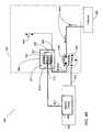
- FIG. 2Aillustrates an exemplary surgical system in a functional block diagram that shows the vacuum regulated aspiration components and interfaces that may be employed in accordance with an aspect of the present design
- FIG. 2Billustrates an exemplary surgical system in a functional block diagram that shows the pressure regulated infusion components and interfaces that may be employed in accordance with an aspect of the present design
- FIG. 3Aillustrates a capacitive fluid level sensing system for a surgical cassette reservoir including an electric circuit where a single pair of planar plates, i.e. two conductors, forms a capacitor;
- FIG. 3Billustrates a capacitive fluid level sensing system for a surgical cassette reservoir including an electric circuit where a single pair of interleaved plates, i.e. two conductors, forms a capacitor;
- FIG. 3Cillustrates a capacitive fluid level sensing system for a surgical cassette reservoir including an electric circuit where multiple planar plate pairs, i.e. two conductors, forms multiple capacitors;
- FIG. 3Dillustrates the horizontal cross-section for an embodiment where an optical fluid-sensing chamber forms part of the overall evacuation chamber and a single pair of capacitive plates are positioned in close proximity to the fluid sensing chamber;
- FIG. 3Eillustrates an exemplary electric circuit configured as a RC circuit in accordance with an aspect of the present design
- FIG. 3Fillustrates an approximate voltage response for the present design electric circuit in accordance with an aspect of the present design
- FIG. 3Gillustrates an exemplary electric circuit configured in accordance with an aspect of the present design
- FIG. 4Ais a functional block diagram illustrating a surgical cassette system configured for peristaltic pump outflow operation in accordance with the present design.
- FIG. 4Bis a functional block diagram illustrating a surgical cassette system configured for peristaltic pump inflow operation in accordance with the present design.
- the present designis directed to sensing fluid levels in a reservoir in a system, such as, but not limited to sensing the fluid level within a surgical cassette's integrated air-fluid reservoir and mechanized controlling of the fluid level within the reservoir.
- the present arrangementmay include a device, such as a pump (peristaltic, venturi, flow or vacuum based pump, etc.), configured to provide outflow/inflow of fluid from the air-fluid reservoir and move the fluid to/from a collector such as a collection bag for purposes of maintaining proper balance of air and fluid in the reservoir.
- Any pump known in the artmay be used with the present invention, including, but not limited to, peristaltic, venturi (wherein fluid flowing through a narrowing pipe produces vacuum as a result of the “Venturi effect”), and/or other flow or vacuum based pumps.
- the present designmay employ a capacitive fluid level-sensor device with the air-fluid reservoir for sensing the level of fluid within the cassette's reservoir.
- the capacitive fluid level-sensor devicemay be in any orientation with respect to a fluid maintaining device, such as a reservoir, including, but not limited to attached inside and/or outside the walls of the fluid maintaining device and/or external to the fluid maintaining device, but not attached to the device.
- a phacoemulsification system(“phaco system”) may provide for vacuum regulated aspiration, where a surgeon performing an ocular surgery may remove a large volume of fluid and material from the patient's eye. Vacuum regulated aspiration may increase the fluid level within the surgical cassette's reservoir in a relatively short amount of time. If the reservoir receives too much fluid, the level may rise above an acceptable level and may inhibit performance. For example, a rise in fluid level above certain reservoir fluid connections may cause the phaco system to operate improperly or stop.
- the phaco systemmoves fluid from the eye to a reservoir.
- the phaco systemmay operate a pump and/or valve configured to move the fluid from the reservoir and into a collector.
- the present design's capacitive fluid level sensing systemmay include an electric circuit configured to measure a change in capacitance, such as a rise in capacitance when the reservoir fluid level increases, and a fall in capacitance when the level decreases from the capacitive fluid level sensor device.
- the electric circuitcould be configured to measure a preset maximum and/or minimum threshold, or a change rate of capacitance.
- the systemproduces a control signal to start and stop a pump situated between the reservoir and collector.
- the systemcan operate the pump to add or remove fluid from the reservoir when the level falls outside of preset thresholds, either upper or lower, and stop the pump when the level is restored within the desired operational range.
- a surgeon performing an ocular surgical proceduremay input the desired thresholds via the instrument host system or GUI host prior to surgery. In this way, the present design may allow the surgeon to focus on the ocular procedure without the need to monitor and manually adjust the air-to-fluid ratio or balance within the reservoir.
- the present designcomprises a fluid level sensing arrangement that may be used with a medical instrument system, such as a phaco system.
- a medical instrument systemsuch as a phaco system.
- the systemcan be provided with a reservoir in a surgical cassette system together with a pump and/or valve to control the flow of fluid to and/or from the reservoir.
- Newer cassettescan support aspiration and irrigation functionality, enabling a surgeon to control the operation of the phacoemulsification/vitrectomy system handpiece.
- the present designis intended to provide reliable, noninvasive, and efficient fluid level sensing in a medical instrument system for use in efficiently controlling the flow of fluids between the reservoir and the collector during an ocular procedure.
- one embodiment of the present designis in or with a phaco system that comprises an independent graphical user interface (GUI) host module, an instrument host module, a GUI device, and a controller module, such as a foot switch, to control the phaco system.
- GUIgraphical user interface
- FIG. 1illustrates an exemplary phaco/vitrectomy system 100 in a functional block diagram to show the components and interfaces for a safety critical medical instrument system that may be employed in accordance with an aspect of the present invention.
- a serial communication cable 103connects GUT host 101 module and instrument host 102 module for the purposes of controlling surgical instrument host 102 by GUI host 101 .
- GUI host 101 and instrument host 102as well as any other component of system 100 may be connected wirelessly.
- Instrument host 102may be considered a computational device in the arrangement shown, but other arrangements are possible.
- An interface communications cable 120is connected to instrument host 102 module for distributing instrument sensor data 121 , and may include distribution of instrument settings and parameters information, to other systems, subsystems and modules within and external to instrument host 102 module. Although shown connected to instrument host 102 module, interface communications cable 120 may be connected or realized on any other subsystem (not shown) that could accommodate such an interface device able to distribute the respective data.
- a switch module associated with foot pedal 104may transmit control signals relating internal physical and virtual switch position information as input to the instrument host 102 over serial communications cable 105 (although footpedal 104 may be connected wirelessly).
- Instrument host 102may provide a database file system for storing configuration parameter values, programs, and other data saved in a storage device (not shown), such as upper and lower fluid level preset thresholds for the reservoir.
- the database file systemmay be realized on GUI host 101 or any other subsystem (not shown) that could accommodate such a file system.
- Phaco/vitrectomy system 100has a handpiece 110 that includes a needle and electrical means, typically a piezoelectric crystal, for ultrasonically vibrating the needle.
- Instrument host 102supplies power on line 111 to a phacoemulsification/vitrectomy handpiece 110 .
- An irrigation fluid source 112can be fluidly coupled to handpiece 110 through line 113 .
- the irrigation fluid and ultrasonic powerare applied by handpiece 110 to a patient's eye, or affected area or region, indicated diagrammatically by block 114 .
- the irrigation sourcemay be routed to eye 114 through a separate pathway independent of the handpiece.
- Aspirationis provided from eye 114 by a pump (not shown), via instrument host 102 , through lines 115 and 116 .
- a surgeon/operatormay select an amplitude of electrical pulses either using handpiece 110 or via instrument host 102 and GUI host 101 .
- the present systemenables aspiration or irrigation functionality in or with the phaco system and may comprise components including, but not limited to, a flow selector valve, one or more pumps, a reservoir, and a collector, such as a collection bag or a device having similar functionality.
- the fluid sensing employedis described with respect to a phaco system having dual pump capability and employing a reservoir, such as the “Signature” system available from Advanced Medical Optics, Inc., of Santa Ana, Calif.
- a phaco system having dual pump capability and employing a reservoirsuch as the “Signature” system available from Advanced Medical Optics, Inc., of Santa Ana, Calif.
- the present discussionreferences operational features and functionality in context with systems such as the AMO “Signature” System, the present design is not limited to designs involving dual pump capability or a replaceable cassette and may apply to virtually any fluid based medical design where accurate fluid level measurement is desirable.
- FIG. 2Aillustrates an exemplary surgical system in a functional block diagram that shows the vacuum regulated aspiration components and interfaces that may be employed in accordance with an aspect of the present design.
- FIG. 28illustrates the exemplary surgical system including components and interfaces for pressure regulated infusion functions.
- the present designeffectively connects the aspiration-infusion line from the handpiece to the air-fluid reservoir, and the reservoir is also connected to the collector through a peristaltic line.
- the peristaltic connection between the reservoir and collectorincludes a peristaltic pump configured to operate in the clockwise and counterclockwise directions.
- Surgical cassette venting system 200may include a fluid vacuum sensor 201 , flow selector valve 202 , reservoir 204 , collector 206 , and fluid pathways, such as interconnecting surgical tubing, as shown in FIG. 2 .
- Cassette arrangement 250may include connections to facilitate easy attachment to and removal from instrument host 102 as well as handpiece 110 and vacuum pump arrangement 207 .
- the present designcontemplates two pumps, where the surgical cassette arrangement may operate with fluid pathways or other appropriate fluid interconnections interfacing with the two pumps.
- Cassette arrangement 250is illustrated in FIGS. 2A and 2B to show components that may be enclosed within the cassette.
- the size and shape of cassette 250is not to scale nor accurately sized, and note that certain components, notably peristaltic pump 203 , interface with the cassette but in actuality form part of the device which the cassette attaches to. Further, more or fewer components may be included in the cassette than are shown in FIGS. 2A and 2B depending on the circumstances and implementation of cassette arrangement 250 .
- handpiece 110is connected to the input side of fluid vacuum sensor 201 , typically by fluid pathways such as fluid pathway 220 .
- the output side of fluid vacuum sensor 201is connected to flow selector valve 202 within cassette arrangement 250 via fluid pathway 221 .
- the present designmay configure flow selector valve 202 to interface between handpiece 110 , balanced saline solution (BSS) fluid bottle 112 , pump 203 , which is shown as a peristaltic pump but may be another type of pump, and reservoir 204 .
- BSSbalanced saline solution
- pump 203which is shown as a peristaltic pump but may be another type of pump
- reservoir 204the system may operate flow selector valve 202 to connect handpiece 110 with BSS fluid bottle 112 , reservoir 204 and/or with pump 203 based on signals received from instrument host 102 resulting from the surgeon's input to GUI host 101 .
- Flow selector valve 202 illustrated in FIGS. 2A and 2Bprovides a single input port and may connect port ‘0’ to one of three available ports numbered ‘1’, ‘2’, and ‘3’.
- Flow selector valve 202may also be one or more pinch valves.
- Reservoir 204may contain air in section 211 and fluid in section 212 and fluid may move up or down as indicated by arrow 245 .
- Surgical cassette system 200may connect reservoir 204 with collector 206 using fluid pathways, such as surgical tubing or similar items.
- pump 205may operate in a clockwise direction in the direction of arrow 228 to remove fluid from reservoir 204 through fluid pathway 227 and deliver the fluid to collector 206 using fluid pathway 229 .
- the present designillustrates a peristaltic pump as pump 205 , a component within instrument host 102 , but other types of pumps may be employed. This configuration may enable surgical cassette 200 to remove unwanted fluid and/or material from reservoir 204 . Fluid may alternately pass through fluid pathway 223 to pump 203 , fluid pathway 225 , and into collector 206 in certain situations.
- the fluid pathways or flow segments of surgical cassette system 200may include the fluid connections, for example flexible tubing, between each component represented with solid lines in FIGS. 2A and 2B .
- Vacuum pump arrangement 207is typically a component within instrument host 102 , and may be connected with reservoir 204 via fluid pathway or flow segment 230 .
- vacuum pump arrangement 207includes a pump 208 , such as a venturi pump and an optional pressure regulator 209 (and valve (not shown)), but other configurations are possible.
- vacuum pump arrangement 207may operate to remove air from the top of reservoir 204 and deliver the air to atmosphere (not shown). Removal of air from reservoir 204 in this manner may reduce the pressure within the reservoir, which reduces the pressure in the attached fluid pathway 226 , to a level less than the pressure within eye 114 .
- a lower reservoir pressure connected through flow selector valve 202may cause fluid to move from the eye, thereby providing aspiration.
- Vacuum pump arrangement 207 and reservoir 204can be used to control fluid flow into and out of reservoir 204 .
- the optional pressure regulator 209may operate to add air to the top of reservoir 204 which in turn increases pressure and may force air-fluid boundary 213 to move downward. Adding air into reservoir 204 in this manner may increase the air pressure within the reservoir, which increases the pressure in the attached fluid aspiration line 226 to a level greater than the pressure within eye 114 . A higher reservoir pressure connected through flow selector valve 203 may cause fluid to move toward eye 114 , thereby providing venting or reflux.
- FIG. 2Billustrates an optional embodiment illustrating a surgical cassette system 200 configured for venting and/or reflux operation.
- the FIG. 2B designmay configure flow selector valve 202 to connect handpiece 110 with reservoir 204 from port ‘2’ to port ‘0’.
- Vacuum pump arrangement 207may operate to provide pressure to reservoir 204 via pressure regulator 209 . Applying or increasing pressure using pressure regular 209 of vacuum pump arrangement 207 may move air-fluid boundary 213 downward in the direction of arrow 245 causing fluid to flow from reservoir 204 and/or fluid pathway 226 to eye 114 .
- the present designprovides an alternative to optical fluid level sensing techniques, for example infrared sensing, and sound sensing techniques, such as ultrasonic sensing techniques.
- the present designincludes a capacitive fluid level sensing technique wherein a capacitive fluid level-sensor device, typically a conductive plate pair forming a capacitor, is employed with a reservoir.
- the capacitive sensor devicemay connect to an electric circuit configured to measure the capacitance or electric charge stored by the capacitive sensor device, i.e. between the two conductive plates.
- the electric circuitmay communicate the measurement as a signal to a phacoemulsification instrument host for purposes of determining the fluid level based on the measured amount of charge stored.
- the circuitmay communicate the measurement as a signal to a separate or self-contained fluid level control circuit, such as, but not limited to that shown in FIG. 3G .
- a pumpmay be operated to add or remove fluid from the reservoir.
- Equation (1)shows that capacitance is directly proportional to permittivity of the dielectric material situated between the plates.
- the relative permittivity of air to a vacuumis 1.00054 or approximately 1.0.
- the relative permittivity of water relative to a vacuum, depending on temperature, etc.is approximately 80 times greater than air, and salt water is approximately 10 times greater.
- the relative permittivity of the balanced salt solution (BSS) fluid used for phacoemulsificationis significantly greater than air.
- the large difference in permittivity between air and BSSmay allow the present design's capacitive fluid level sensing system to measure the fluid level in a reservoir or tank.
- Arranging a capacitive fluid level-sensor device with the reservoirmay store an electric charge that changes proportional to the amount of fluid stored in the reservoir.
- the capacitive sensing devicemay include parallel or planar plates that may extend from the bottom to the top of the reservoir, but may also extend to any location in between.
- the capacitance formed by the present design's plate pairsis at a minimum when the reservoir is empty, i.e. full of air, and is at a maximum when the reservoir is full, i.e. full of fluid.
- FIGS. 3A-3Eillustrate various exemplary embodiments for the present design capacitive fluid sensing system 300 .
- Other configurations of the conductive platesare also envisioned by the present invention, including, but not limited to, different sizes (length, width, etc.), shapes, and/or orientations with respect to each conductive plate and/or each plate pair and with respect to the reservoir.
- conductive platesmay be positioned on opposite sides of the reservoir or at different areas within the same plane of the reservoir wall.
- FIG. 3Ashows conductive plate pairs oriented in a single plane.
- FIG. 3Bshows interleaving of plate pairs that may provide a higher capacitance
- FIG. 3Cshows multiple fluid level sensors configured at different heights.
- the present designmay provide conductive plate pairs along the walls of the reservoir, external to the reservoir, or otherwise within the reservoir for measuring fluid level in the reservoir.
- the present designmay sense fluid level at multiple distinct heights within the reservoir by arranging plate pairs at a number of discrete points, such as at a high, middle, and a low position within the reservoir.
- FIG. 3Dillustrates the horizontal cross-section for an existing embodiment in a representative system.
- an optical fluid-sensing chamberforms part of the overall evacuation chamber.
- the optical fluid level-sensing chambermay extend the full vertical length of the evacuation chamber, not shown in FIG. 3D .
- FIG. 3Aillustrates a capacitive fluid level sensing system 300 for a reservoir 204 that may be internal or external to a device such as a surgical cassette 250 .
- Electric circuit 350comprises a pair of plates, i.e. two conductors, forming a capacitor.
- the present designmay orient the two plates in a parallel orientation or planar alignment with respect to each other as illustrated in FIG. 3A .
- the plate orientation for the present designis not limited to parallel or planar arrangements, however planar plates may provide advantages when attached in close proximity to the outside of the cassette as illustrated in FIG. 3D .
- the platesnotably may be part of the instrument into which the cassette including the reservoir is inserted. Plates may therefore be positioned outside the reservoir, outside the cassette, and on the instrument into which the cassette is mounted. An example of this type of mounting or operation is provided in FIG. 3D .
- plates attached to the reservoirthey may be inside or outside the reservoir. Preference may be outside to prevent a direct connection through conductive fluid to the electronics. If inside, the plates are electrically isolated from the fluid, such as by use of insulation or other isolating methodology known in the art.
- capacitive fluid level sensing system 300includes plate 302 and plate 303 as a pair, and are attached to the outside of reservoir 204 within cassette 250 separated by a distance d as shown at point 304 .
- the present designmay electrically connect plate 302 to electric circuit 350 at point 351 and plate 303 may connect at point 352 .
- the connectionsmay be realized using a pogo pin male type connector, or equivalent connector, configured to plug into a companion pogo pin female connector provided as part of instrument host 102 circuit 350 .
- Electric circuit 350may include electrical components, such as passive devices such as resistors and active devices such as diodes connected to a signal source, such as a square-wave generator to drive the circuit between the two plates. Driving the electric circuit in this manner may allow for measuring the amount of electric charge stored, or capacitance, by the plate pair capacitor arrangement inside reservoir 204 .
- System 300may sense and determine the fluid level within reservoir 204 in relation to the amount of charge measured between the present design's plate pair, plate 302 and plate 303 .
- the plate pairmay be integrated with reservoir 204 by spraying or coating a conductive paint on the inside or outside of reservoir 204 .
- the platesmay be implemented by applying conductive tape, such as copper with an adhesive backing, to the inside or outside of reservoir 204 .
- the platesmay be implemented as conductive surfaces in close proximity to reservoir 204 but built into the surgical instrument. Other connection methods may be employed, including but not limited to suspending the plates in reservoir 204 .
- the present designmay include an electric circuit 350 to exhibit a typical resistor-capacitor (RC) circuit.
- V Iis the voltage of the square wave applied across the plates
- Ris the resistance of a resistor configured in series with the plate pair
- Cis the plate capacitance
- tequals time. Configuring an RC circuit in this manner may allow the present design to measure the RC voltage response of circuit 350 and thus determine the capacitance using Equation (2).
- Capacitive fluid level sensing system 300may measure the capacitance resulting from at least one plate pair using electric circuit 350 and communicate a signal, for example the voltage response, indicating an increase or decrease in capacitance to instrument host 102 as a result of an increase or decrease in fluid shown at 310 .
- Instrument host 102may control a pump to operate and move fluid from the reservoir to the collector based on a communicated increase in capacitance, preset maximum threshold, or capacitance change rate.
- the instrument host 102may control a pump to operate and move fluid from the collector to the reservoir based on a communicated decrease in capacitance, preset minimum threshold, or capacitance change rate.
- FIG. 3Billustrates a capacitive fluid level sensing system 300 for a surgical cassette 250 reservoir 204 including electric circuit 350 where a single pair of plates, i.e. two conductors, forms a capacitor.
- the illustration of FIG. 3Bshows two interleaved conductive plates oriented as illustrated in FIG. 3B .
- the plates in FIG. 3Bare termed stepped plates, where stepped plates comprise a main or base plate oriented at one angle with plate steps or protrusions oriented orthogonally to the main or base plate as shown. Operation may be as discussed above, wherein system 300 and the circuitry shown may sense and determine the fluid level within reservoir 204 in relation to the amount of charge measured between interleaved plate 305 and plate 306 .
- FIG. 3Cillustrates a further capacitive fluid level sensing system 300 where three pairs of conductive plates form three distinct capacitors.
- the present designmay orient the three pairs in a horizontal direction, each pair comprising two parallel plates, each pair at differing heights within reservoir 204 as illustrated n FIG. 3C .
- capacitive fluid level sensing system 300may fix or attach a first set of plates 309 , a mid level set of plates 308 , and a third lower level positioned set of plates 307 to the inside of reservoir 204 within cassette 250 separated in a multiple height configuration.
- Sets of plates 307 , 308 , and 309may be electrically connected to electric circuit 355 at 356 as shown in FIG. 3C .
- Driving the electric circuit in the manner as previously described for FIG. 3Amay allow for measuring the amount of electric charge stored, or capacitance, at each plate pair arrangement configured inside reservoir 204 .
- System 300may sense the fluid level within reservoir 204 in relation to the amount of charge measured between the present designs plates at 309 , 308 , and 307 as previously described for electric circuit 350 .
- capacitive fluid sensing system 300may measure the capacitance resulting from multiple plate pairs using electric circuit 355 and communicate a signal indicating a change (e.g. an increase or decrease in capacitance) at each measurement height to instrument host 102 as a result of an increase or decrease in fluid shown by arrow 310 .
- the present designmay individually detect capacitance at each plate pair, using individual measuring circuits, to indicate when fluid has reached and covered the plates.
- Instrument host 102may control a pump, such as a peristaltic pump, to operate and move fluid from reservoir 204 to the collector based on a communicated capacitance at each height. For example, if all three capacitors report a low capacitance value to instrument host 102 , the host may determine that the fluid level is low and may control the peristaltic pump to operate and move fluid from the collector or other fluid source to reservoir 204 .
- a pumpsuch as a peristaltic pump
- the previously described embodimentsdisclose designs that attach capacitive plates internally and/or externally to the reservoir. Designs that involve placement of plates, attached inside or outside of the reservoir, may reduce reliability and potentially become unsafe. Reliability in these designs may be reduced by the need to provide electrical connections from the plates within the cassette to the electric circuit. Designs that involve placement of the plates inside the reservoir may potentially complete a direct connection formed between the patient and conductive fluid to the electronics, which can be undesirable.
- the present designmay involve configuring the capacitive plates with and as part of the instrument host system. The plates may therefore be integrated in the instrument host system and may be arranged in close proximity to the holding mechanism, or cavity, where the cassette is located. This eliminates the need for electrical connections within the reservoir.
- FIG. 3Dillustrates the horizontal cross-section for one such integrated system where a fluid chamber 385 , such as a reservoir similar to reservoir 204 shown in FIG. 2A , forms part of the cassette design.
- the present designmay fix plate pair 360 , 370 on the outside of fluid chamber 385 as shown in FIG. 3D , where chamber wall 380 is shown, and an electrical connection may be provided between the plates and the electric circuit within instrument host 102 (not shown in FIG. 3D ).
- the systemmay include plates 360 , 370 on the outside of a small cavity associated with instrument host 102 configured to hold fluid chamber 385 flush between the plate pair once inserted into the cavity by an operator.
- Flush mounting fluid chamber 385 in this mannermay minimize the distance between the plates and maximize the change in capacitance observed while mitigating the need for unreliable electrical connections by using permanent connections between the plates and electric circuit configured with instrument host 102 .
- the capacitance formed between plates 360 , 370increases, and conversely, as fluid falls in fluid chamber 385 , the capacitance decreases between plates 360 , 370 .
- FIG. 3Eillustrates an exemplary electric circuit 350 configured as a RC circuit in accordance with an aspect of the present design.
- the present designmay arrange a resistor 390 and a signal source 391 with two conductive plates 392 .
- the voltage response for electric circuit 350is measured between ‘A’ at point 395 and point ‘B’ at point 394 .
- FIG. 3FAn approximate voltage response for the capacitive sensor is illustrated in FIG. 3F .
- the responseis plotted as voltage (on axis 396 ) versus time (on axis 397 ).
- the response curve for plates submerged by fluidis shown as response 398 and the voltage response for plates in air is shown as response 399 .
- Measurements for a pair of conductive plates in air versus submerged in BSSyield approximately a 2 to 1 change in the observed capacitance.
- FIG. 3Gillustrates an exemplary fluid level sensing system that may involve capacitive plates to realize variable capacitor 360 and may connect variable capacitor 360 to a capacitance to frequency converter 361 .
- Converter 361may vary frequency output signal 362 (f(C)) in response to the capacitance measured at capacitor 360 .
- Fluid level sensing and control circuit 363may receive frequency output signal 362 and based on this frequency output signal may operate pump 205 by turning it on or off using a control signal transmitted over line 364 .
- control circuit 363processes frequency output signal 362 and turns on pump 205 , fluid is removed from reservoir 204 and moved to collector 206 as previously described.
- Additional circuitsmay include, but are not limited to, varying output voltage, current, pulse width, or duty cycle in response to changes in input capacitance or a constant current charge measuring circuit.
- FIGS. 3A , 3 C, 3 D, and 3 Eillustrate or suggest a rectangular shape for the plates
- the shape of the platesare not limited to geometric or rectangular shapes, and may be realized using customized shapes.
- the illustrations that form FIGS. 3A-Dare generally not drawn to scale and are for illustrative purposes.
- FIGS. 4A and 4Billustrate two modes of operation for the present design.
- the first modeis illustrated in FIG. 4A , where capacitive fluid sensing system 400 with surgical cassette 250 may employ peristaltic pump 205 to move fluid from reservoir 404 to collector 206 as a result of a high level of fluid in reservoir 404 .
- plate pairs 306 , 307 , and 308all may report a high capacitance to electric circuit 406 via a connection 405 due to fluid covering the three plate pairs.
- Electric circuit 406may convert the reported capacitance into a voltage response sufficient to indicate to instrument host 102 to operate peristaltic pump 205 via connection 407 to pump fluid from reservoir 404 to collector 206 .
- capacitive fluid sensing system 400 with surgical cassette 250may configure peristaltic pump 205 for pumping or moving of fluid from collector 206 and/or fluid pathways between collector 206 and reservoir 404 , to reservoir 404 due to a low level of fluid in reservoir 404 .
- plate pairs 306 , 307 , and 308all may report a low capacitance to electric circuit 406 via a connection 405 when air-fluid boundary 215 is below plate pair 306 .
- Electric circuit 406may convert the reported capacitance into a voltage response sufficient to indicate to instrument host 102 to operate peristaltic pump 205 via connection 407 in a counter clock-wise direction 420 b to pump fluid from collector 206 and/or fluid pathways between collector 206 and reservoir 404 , to reservoir 404 .
- the present design of a capacitive fluid level sensing systemprovides for automatic draining or filling of fluid within a reservoir during an ocular procedure by operating a pump, for example a vacuum, venturi, or peristaltic pump, using capacitive sensing.
- a pumpfor example a vacuum, venturi, or peristaltic pump
- the present designdoes not require a fluid float mechanism and thus is free of incorrect measurements due to a stuck or “sunk” float condition.
- the presence of BSS beads and condensation on the sides of the reservoir tank that make optical level detection difficultgenerally do not sufficiently alter the measured capacitance because the fluid volume between the plates is not significantly changed.
- automatic or semi-automatic operationentails sensing a change in capacitance and either drains fluid from the reservoir or pumps fluid into the reservoir. In any circumstance, the surgeon or other personnel are provided with the ability to run the pumps in any available direction, such as for cleaning purposes.
Landscapes
- Health & Medical Sciences (AREA)
- Engineering & Computer Science (AREA)
- Physics & Mathematics (AREA)
- Power Engineering (AREA)
- Heart & Thoracic Surgery (AREA)
- Public Health (AREA)
- Life Sciences & Earth Sciences (AREA)
- Veterinary Medicine (AREA)
- Anesthesiology (AREA)
- Biomedical Technology (AREA)
- General Health & Medical Sciences (AREA)
- Hematology (AREA)
- Animal Behavior & Ethology (AREA)
- General Physics & Mathematics (AREA)
- Thermal Sciences (AREA)
- Electromagnetism (AREA)
- Fluid Mechanics (AREA)
- Vascular Medicine (AREA)
- Pulmonology (AREA)
- External Artificial Organs (AREA)
- Infusion, Injection, And Reservoir Apparatuses (AREA)
Abstract
Description
C=∈*A/d (1)
where C is capacitance, ∈ is permittivity of the dielectric between the two plates, A is the area of the plate, and d is the distance between conductive plates. Simply put, Equation (1) shows that capacitance is directly proportional to permittivity of the dielectric material situated between the plates. The relative permittivity of air to a vacuum is 1.00054 or approximately 1.0. The relative permittivity of water relative to a vacuum, depending on temperature, etc., is approximately 80 times greater than air, and salt water is approximately 10 times greater. The relative permittivity of the balanced salt solution (BSS) fluid used for phacoemulsification is significantly greater than air. The large difference in permittivity between air and BSS may allow the present design's capacitive fluid level sensing system to measure the fluid level in a reservoir or tank.
Vo=VI*(1−e−t/RC) (2)
where Vois the measured voltage between the top of
Claims (32)
VO(p)=VI(p)*(1−e−t/RC)
VO(p)=VI(p)*(1−e−t/RC)
VO(p)=VI(p)*(1−e−t/RC)
Priority Applications (6)
| Application Number | Priority Date | Filing Date | Title |
|---|---|---|---|
| US12/267,214US8469050B2 (en) | 2008-11-07 | 2008-11-07 | Capacitive fluid level sensing |
| CA2733111ACA2733111C (en) | 2008-11-07 | 2009-11-06 | Capacitive fluid level sensing |
| PCT/US2009/063505WO2010054162A2 (en) | 2008-11-07 | 2009-11-06 | Capacitive fluid level sensing |
| EP09825454.3AEP2341877A4 (en) | 2008-11-07 | 2009-11-06 | Capacitive fluid level sensing |
| AU2009313433AAU2009313433B2 (en) | 2008-11-07 | 2009-11-06 | Capacitive fluid level sensing |
| US13/899,917US9604043B2 (en) | 2008-11-07 | 2013-05-22 | Capacitive fluid level sensing |
Applications Claiming Priority (1)
| Application Number | Priority Date | Filing Date | Title |
|---|---|---|---|
| US12/267,214US8469050B2 (en) | 2008-11-07 | 2008-11-07 | Capacitive fluid level sensing |
Related Child Applications (1)
| Application Number | Title | Priority Date | Filing Date |
|---|---|---|---|
| US13/899,917DivisionUS9604043B2 (en) | 2008-11-07 | 2013-05-22 | Capacitive fluid level sensing |
Publications (2)
| Publication Number | Publication Date |
|---|---|
| US20100121257A1 US20100121257A1 (en) | 2010-05-13 |
| US8469050B2true US8469050B2 (en) | 2013-06-25 |
Family
ID=42153571
Family Applications (2)
| Application Number | Title | Priority Date | Filing Date |
|---|---|---|---|
| US12/267,214Active2029-08-31US8469050B2 (en) | 2008-11-07 | 2008-11-07 | Capacitive fluid level sensing |
| US13/899,917Active2030-07-24US9604043B2 (en) | 2008-11-07 | 2013-05-22 | Capacitive fluid level sensing |
Family Applications After (1)
| Application Number | Title | Priority Date | Filing Date |
|---|---|---|---|
| US13/899,917Active2030-07-24US9604043B2 (en) | 2008-11-07 | 2013-05-22 | Capacitive fluid level sensing |
Country Status (5)
| Country | Link |
|---|---|
| US (2) | US8469050B2 (en) |
| EP (1) | EP2341877A4 (en) |
| AU (1) | AU2009313433B2 (en) |
| CA (1) | CA2733111C (en) |
| WO (1) | WO2010054162A2 (en) |
Cited By (5)
| Publication number | Priority date | Publication date | Assignee | Title |
|---|---|---|---|---|
| US20120184932A1 (en)* | 2011-01-17 | 2012-07-19 | Medela Holding Ag | Drainage pump unit |
| US20180321072A1 (en)* | 2017-05-03 | 2018-11-08 | Nypro Inc. | Apparatus, system, and method of providing a liquid level monitor |
| US11723801B2 (en)* | 2017-11-10 | 2023-08-15 | Crea Ip B.V. | Method and system for active irrigation of an ophthalmic surgical site |
| US11982558B2 (en) | 2018-05-03 | 2024-05-14 | Nypro Inc. | Apparatus, system, and method of providing a content level monitor |
| US11982557B2 (en) | 2018-05-03 | 2024-05-14 | Nypro Inc. | Apparatus, system, and method of providing a solids level monitor |
Families Citing this family (55)
| Publication number | Priority date | Publication date | Assignee | Title |
|---|---|---|---|---|
| US10912869B2 (en) | 2008-05-21 | 2021-02-09 | Smith & Nephew, Inc. | Wound therapy system with related methods therefor |
| US8414519B2 (en) | 2008-05-21 | 2013-04-09 | Covidien Lp | Wound therapy system with portable container apparatus |
| US8827983B2 (en) | 2008-08-21 | 2014-09-09 | Smith & Nephew, Inc. | Sensor with electrical contact protection for use in fluid collection canister and negative pressure wound therapy systems including same |
| US9526920B2 (en) | 2010-10-12 | 2016-12-27 | Smith & Nephew, Inc. | Medical device |
| ES2912362T3 (en) | 2010-11-09 | 2022-05-25 | Aegea Medical Inc | Method of placement and apparatus for delivering steam to the uterus |
| CN103619374B (en)* | 2010-12-07 | 2017-07-11 | 措尔生命桥梁有限责任公司 | Method and system for filling and venting a device for extracorporeal blood treatment with a stepwise filling of the filter |
| GB201100044D0 (en)* | 2011-01-04 | 2011-02-16 | Avelec Ltd | Fluid level sensor apparatus |
| DE102011053407A1 (en)* | 2011-09-08 | 2013-03-14 | Beko Technologies Gmbh | level monitoring |
| CA2851355C (en) | 2011-10-07 | 2020-02-18 | Aegea Medical Inc. | Integrity testing method and apparatus for delivering vapor to the uterus |
| US8585636B2 (en)* | 2011-11-18 | 2013-11-19 | Abbott Medical Optics Inc. | Medical device receptacle filling method and apparatus |
| WO2013122677A1 (en)* | 2012-02-17 | 2013-08-22 | Sabic Innovative Plastics Ip B.V. | Apparatus and method for liquid level measurement in electrolytic cells |
| EP2852333B1 (en) | 2012-05-22 | 2021-12-15 | Smith & Nephew plc | Apparatuses for wound therapy |
| US9119701B2 (en) | 2012-10-22 | 2015-09-01 | Alcon Research, Ltd. | Pressure control in phacoemulsification system |
| JP2016517318A (en) | 2013-03-14 | 2016-06-16 | スミス アンド ネフュー インコーポレーテッド | System and method for administering decompression therapy |
| US9737649B2 (en) | 2013-03-14 | 2017-08-22 | Smith & Nephew, Inc. | Systems and methods for applying reduced pressure therapy |
| US9898584B2 (en)* | 2013-03-15 | 2018-02-20 | Abbott Medical Optics Inc. | System and method for providing a common medical device architecture |
| WO2015023515A1 (en) | 2013-08-13 | 2015-02-19 | Smith & Nephew, Inc. | Systems and methods for applying reduced pressure therapy |
| US20150129039A1 (en)* | 2013-11-12 | 2015-05-14 | Hamilton Beach Brands, Inc. | Beverage Maker with Capacitance Fluid Level Sensor |
| US9347813B2 (en) | 2014-01-28 | 2016-05-24 | Analog Devices GmbH | Capacitive sensing probe motion control system |
| US10617805B2 (en) | 2014-03-20 | 2020-04-14 | Exploramed Nc7, Inc. | Fluid measuring reservoir for breast pumps |
| US10179019B2 (en) | 2014-05-22 | 2019-01-15 | Aegea Medical Inc. | Integrity testing method and apparatus for delivering vapor to the uterus |
| CA3179001A1 (en) | 2014-07-31 | 2016-02-04 | Smith & Nephew, Inc. | Systems and methods for applying reduced pressure therapy |
| US12133789B2 (en) | 2014-07-31 | 2024-11-05 | Smith & Nephew, Inc. | Reduced pressure therapy apparatus construction and control |
| US9476752B2 (en)* | 2014-10-01 | 2016-10-25 | Sealed Air Corporation | Fluid level sensor |
| KR102342565B1 (en) | 2014-12-30 | 2021-12-23 | 삼성전자주식회사 | Oil level detecting apparatus and control method thereof, oil flow detecting apparatus and control method thereof, method for control oil return using oil level and oil flow |
| CA2972701A1 (en) | 2014-12-30 | 2016-07-07 | Smith & Nephew, Inc. | Systems and methods for applying reduced pressure therapy |
| US10463780B2 (en)* | 2015-01-29 | 2019-11-05 | Johnson & Johnson Surgical Vision, Inc. | Fluid depletion warning system for phacoemulsification surgical applications |
| WO2016164853A1 (en)* | 2015-04-08 | 2016-10-13 | Naya Health, Inc. | Fluid measuring reservoir for breast pumps |
| US10744712B2 (en)* | 2015-08-28 | 2020-08-18 | Formlabs, Inc. | Techniques for fluid sensing during additive fabrication and related systems and methods |
| EP4393526A3 (en) | 2016-02-12 | 2024-08-14 | Smith & Nephew, Inc | Systems and methods for detecting operational conditions of reduced pressure therapy |
| EP3416551B1 (en) | 2016-02-19 | 2022-10-12 | Aegea Medical Inc. | Apparatus for determining the integrity of a bodily cavity |
| WO2017197021A1 (en)* | 2016-05-11 | 2017-11-16 | Siemens Healthcare Diagnostics Inc. | Quick connection for liquid level sense-enabled metering probe |
| EP3465107A4 (en)* | 2016-06-03 | 2020-01-22 | The Regents of the University of California | WIRELESS REMOTE DETECTION OF CHANGES IN FLUID FILLED CONTAINERS |
| SE541236C2 (en)* | 2016-06-23 | 2019-05-14 | Resaroe Event Ab | Body drainage system comprising a peristaltic pump device |
| FR3071054B1 (en)* | 2017-09-13 | 2021-01-29 | Intersens | PROBE FOR FILLING LIMITER DEVICE FOR LIQUID OIL FUEL TRANSPORT TANK AND CORRESPONDING FILLING LIMITER DEVICE |
| EP3457096B1 (en)* | 2017-09-13 | 2021-07-07 | Intersens | Improved probe for fill limiting device for petroleum fuel transport tank and corresponding fill limiting device |
| US11906336B2 (en) | 2018-01-31 | 2024-02-20 | Hydroacoustics Inc. | Pumpjack production well including venturi fluid sensor and capacitive flow sensor |
| WO2019152591A1 (en)* | 2018-01-31 | 2019-08-08 | Hydroacoustics Inc. | Fluid sensor and pumpjack control system |
| US12173587B2 (en) | 2018-02-07 | 2024-12-24 | Hydroacoustics Inc. | Oil recovery tool and system |
| WO2019157155A1 (en) | 2018-02-07 | 2019-08-15 | Hydroacoustics Inc. | Oil recovery tool and system |
| US11821293B2 (en) | 2018-02-07 | 2023-11-21 | Hydroacoustics. Inc. | Oil recovery tool and system |
| CN112074710B (en)* | 2018-02-08 | 2023-10-13 | 阿札姆家用电器公司 | Device for sensing a liquid level, apparatus using said device and calibration method |
| WO2019160987A2 (en)* | 2018-02-13 | 2019-08-22 | L-3 Technologies, Inc. | Dipstick and electronic fluid level sensor |
| ES2985920T3 (en)* | 2018-03-16 | 2024-11-07 | Pitco Frialator Inc | Fluid level detection and control system |
| US10898640B2 (en) | 2018-07-11 | 2021-01-26 | Flex, Ltd. | Visual detection for IV pump tube calibration |
| US11504469B2 (en) | 2018-07-11 | 2022-11-22 | Flex Ltd. | Reed switch detection for IV pump tube calibration |
| US10905821B2 (en)* | 2018-07-11 | 2021-02-02 | Flex, Ltd. | Capacitor detection for IV pump tube calibration |
| US11674838B2 (en) | 2019-04-04 | 2023-06-13 | Poseidon Systems Llc | Capacitive fringe field oil level sensor with integrated humidity and temperature sensing |
| GB201914283D0 (en) | 2019-10-03 | 2019-11-20 | Smith & Nephew | Apparatuses and methods for negative pressure wound therapy |
| US20230103467A1 (en)* | 2019-12-17 | 2023-04-06 | Merck Sharp & Dohme Llc | Non-invasive continuous capacitance level detector |
| CN111150890B (en)* | 2020-01-20 | 2022-07-08 | 西南医科大学附属医院 | An adjustable automatic negative pressure drainage device |
| CN116249566A (en)* | 2020-05-26 | 2023-06-09 | 弗劳恩霍夫应用研究促进协会 | Drug delivery system |
| EP4466532A1 (en) | 2022-01-18 | 2024-11-27 | Fluid Handling LLC. | Fluid sensor |
| WO2023193862A1 (en)* | 2022-04-08 | 2023-10-12 | Coloplast A/S | Fluid detection in irrigation system |
| US20240050274A1 (en)* | 2022-08-09 | 2024-02-15 | Twenty Twenty Therapeutics Llc | Proximal ultrasonic water pressure device for ultrafine gauge vitrectomy in combined sampling and drug delivery device |
Citations (43)
| Publication number | Priority date | Publication date | Assignee | Title |
|---|---|---|---|---|
| GB2040464A (en) | 1979-01-05 | 1980-08-28 | Larson R G | Measuring Liquid Level |
| US4464172A (en)* | 1979-04-30 | 1984-08-07 | Lichtenstein Eric Stefan | Computer-control medical care system |
| US4475904A (en)* | 1982-12-29 | 1984-10-09 | Medical Instrument Dev. Labs., Inc. | Fast response vacuum aspiration collection system |
| US4626248A (en)* | 1985-12-16 | 1986-12-02 | Storz Instrument Company | Ophthalmic cassette |
| US4713051A (en)* | 1985-05-21 | 1987-12-15 | Coopervision, Inc. | Cassette for surgical irrigation and aspiration and sterile package therefor |
| US4756238A (en)* | 1986-12-12 | 1988-07-12 | Kyoho Machine Works, Ltd. | Apparatus for performing plural operations on a common workpiece |
| US4773897A (en)* | 1986-11-06 | 1988-09-27 | Storz Instrument Company | Collection container for ophthalmic surgical system |
| US4790816A (en)* | 1985-09-26 | 1988-12-13 | Allon Laboratories, Inc. | Surgical cassette proximity sensing and latching apparatus |
| US5125891A (en)* | 1987-04-27 | 1992-06-30 | Site Microsurgical Systems, Inc. | Disposable vacuum/peristaltic pump cassette system |
| US5135485A (en) | 1991-02-25 | 1992-08-04 | Louis Cohen | Capacitance-type fluid level sensor for i.v. and catheter bags |
| US5324180A (en)* | 1992-09-04 | 1994-06-28 | Allergan, Inc. | Surgical instrument with drawer loading cassette system |
| US5342293A (en)* | 1993-06-22 | 1994-08-30 | Allergan, Inc. | Variable vacuum/variable flow phacoemulsification method |
| US5364342A (en)* | 1992-02-05 | 1994-11-15 | Nestle S.A. | Microsurgical cassette |
| US5568395A (en)* | 1994-06-29 | 1996-10-22 | Lsi Logic Corporation | Modeling and estimating crosstalk noise and detecting false logic |
| US5582601A (en)* | 1994-09-12 | 1996-12-10 | Surgin Surgical Instrumentation, Inc. | Cassette for receiving aspirated fluids |
| US5700240A (en)* | 1994-01-28 | 1997-12-23 | Barwick, Jr.; Billie John | Phacoemulsification system having ultrasonic power controlled by aspiration vacuum sensor |
| US5733256A (en)* | 1996-09-26 | 1998-03-31 | Micro Medical Devices | Integrated phacoemulsification system |
| EP1384945A1 (en) | 2001-04-02 | 2004-01-28 | Autoflame Engineering Limited | Pressurised steam boilers and their control |
| US20050172712A1 (en)* | 2004-02-06 | 2005-08-11 | Nyce David S. | Isolated capacitive fluid level sensor |
| US20050245888A1 (en)* | 2004-04-29 | 2005-11-03 | Cull Laurence J | Combined peristaltic and vacuum aspiration cassette |
| US6971076B2 (en)* | 2001-12-18 | 2005-11-29 | Cadence Design Systems, Inc. | Method for estimating peak crosstalk noise based on separate crosstalk model |
| US20060200068A1 (en)* | 2002-10-21 | 2006-09-07 | Advanced Medical Optics, Inc. | Novel enhanced microburst ultrasonic power delivery system and method |
| US7107837B2 (en)* | 2002-01-22 | 2006-09-19 | Baxter International Inc. | Capacitance fluid volume measurement |
| US20070005029A1 (en) | 2005-06-21 | 2007-01-04 | Hopkins Mark A | Aspiration control |
| WO2007062714A1 (en) | 2005-11-30 | 2007-06-07 | Sie Sensorik Industrie-Elektronik Gmbh | Sensor for the contactless detection of the level of a liquid and adhering high-conductivity medium, especially blood, through a non-metal wall of a container and corresponding method |
| US7326183B2 (en)* | 2005-09-28 | 2008-02-05 | Alcon, Inc. | Intraocular pressure control |
| US20080112842A1 (en)* | 2006-11-09 | 2008-05-15 | Advanced Medical Optics, Inc. | Monitor drape with vents |
| US20080114300A1 (en)* | 2006-11-09 | 2008-05-15 | Advanced Medical Optics, Inc. | Fluidics cassette for ocular surgical system |
| US20080114291A1 (en)* | 2006-11-09 | 2008-05-15 | Advanced Medical Optics, Inc. | Surgical fluidics cassette supporting multiple pumps |
| US20080114290A1 (en)* | 2006-11-09 | 2008-05-15 | Advanced Medical Optics, Inc. | Reversible peristaltic pump and other structures for reflux in eye surgery |
| US20080114311A1 (en)* | 2006-11-09 | 2008-05-15 | Advanced Medical Optics, Inc. | Critical alignment of fluidics cassetts |
| US20080112828A1 (en)* | 2006-11-09 | 2008-05-15 | Advanced Medical Optics, Inc. | Fluidics cassette for ocular surgical system |
| US20080114372A1 (en)* | 2006-11-09 | 2008-05-15 | Advanced Medical Optics, Inc. | Eye treatment system with multiple pumps |
| US20080112889A1 (en)* | 2006-11-14 | 2008-05-15 | Pharmacyclics, Inc. | Uses of Selective Inhibitors of HDAC8 for Treatment of T-Cell Proliferative Disorders |
| US20080114312A1 (en)* | 2006-11-09 | 2008-05-15 | Advanced Medical Optics, Inc. | Eye treatment system with fluidics pump interface |
| US20080114301A1 (en)* | 2006-11-09 | 2008-05-15 | Advanced Medical Optics, Inc. | Holding tank devices, systems, and methods for surgical fluidics cassette |
| US20080125698A1 (en)* | 2006-09-08 | 2008-05-29 | Advanced Medical Optics, Inc. | Systems and methods for power and flow rate control |
| WO2008119993A1 (en) | 2007-04-02 | 2008-10-09 | Huntleigh Technology Limited | Fluid level sensor |
| US20090048607A1 (en)* | 2007-08-13 | 2009-02-19 | Advanced Medical Optics, Inc. | Systems and methods for phacoemulsification with vacuum based pumps |
| US7594901B2 (en)* | 2005-06-21 | 2009-09-29 | Alcon, Inc. | Surgical cassette with multi area fluid chamber |
| US20100249693A1 (en)* | 2009-03-31 | 2010-09-30 | Abbott Medical Optics Inc. | Cassette capture mechanism |
| US20100280434A1 (en)* | 2008-11-07 | 2010-11-04 | Abbott Medical Optics Inc. | Automatically pulsing different aspiration levels to an ocular probe |
| US20100280435A1 (en)* | 2008-11-07 | 2010-11-04 | Abbott Medical Optics Inc. | Automatically switching different aspiration levels and/or pumps to an ocular probe |
Family Cites Families (8)
| Publication number | Priority date | Publication date | Assignee | Title |
|---|---|---|---|---|
| US4083038A (en)* | 1975-06-09 | 1978-04-04 | Elkay Electronics Ltd. | Condenser plate assembly |
| US4933843A (en)* | 1986-11-06 | 1990-06-12 | Storz Instrument Company | Control system for ophthalmic surgical instruments |
| US4749988A (en)* | 1986-11-20 | 1988-06-07 | Imtec Products, Inc. | Non-invasive liquid level sensor |
| US5017909A (en)* | 1989-01-06 | 1991-05-21 | Standex International Corporation | Capacitive liquid level sensor |
| US5406843A (en)* | 1993-10-27 | 1995-04-18 | Kdi Corporation, Inc. | Digital liquid level sensing apparatus |
| US6130377A (en)* | 1998-01-20 | 2000-10-10 | Carlos Avila Rivera | Thermoelectric battery and power plant using the same |
| US7559914B2 (en)* | 2005-12-14 | 2009-07-14 | Alcon, Inc. | Priming a microsurgical system |
| US8465467B2 (en)* | 2006-09-14 | 2013-06-18 | Novartis Ag | Method of controlling an irrigation/aspiration system |
- 2008
- 2008-11-07USUS12/267,214patent/US8469050B2/enactiveActive
- 2009
- 2009-11-06CACA2733111Apatent/CA2733111C/ennot_activeExpired - Fee Related
- 2009-11-06WOPCT/US2009/063505patent/WO2010054162A2/enactiveApplication Filing
- 2009-11-06EPEP09825454.3Apatent/EP2341877A4/ennot_activeWithdrawn
- 2009-11-06AUAU2009313433Apatent/AU2009313433B2/ennot_activeCeased
- 2013
- 2013-05-22USUS13/899,917patent/US9604043B2/enactiveActive
Patent Citations (44)
| Publication number | Priority date | Publication date | Assignee | Title |
|---|---|---|---|---|
| GB2040464A (en) | 1979-01-05 | 1980-08-28 | Larson R G | Measuring Liquid Level |
| US4464172A (en)* | 1979-04-30 | 1984-08-07 | Lichtenstein Eric Stefan | Computer-control medical care system |
| US4475904A (en)* | 1982-12-29 | 1984-10-09 | Medical Instrument Dev. Labs., Inc. | Fast response vacuum aspiration collection system |
| US4713051A (en)* | 1985-05-21 | 1987-12-15 | Coopervision, Inc. | Cassette for surgical irrigation and aspiration and sterile package therefor |
| US4790816A (en)* | 1985-09-26 | 1988-12-13 | Allon Laboratories, Inc. | Surgical cassette proximity sensing and latching apparatus |
| US4626248A (en)* | 1985-12-16 | 1986-12-02 | Storz Instrument Company | Ophthalmic cassette |
| US4773897A (en)* | 1986-11-06 | 1988-09-27 | Storz Instrument Company | Collection container for ophthalmic surgical system |
| US4756238A (en)* | 1986-12-12 | 1988-07-12 | Kyoho Machine Works, Ltd. | Apparatus for performing plural operations on a common workpiece |
| US5125891A (en)* | 1987-04-27 | 1992-06-30 | Site Microsurgical Systems, Inc. | Disposable vacuum/peristaltic pump cassette system |
| US5135485A (en) | 1991-02-25 | 1992-08-04 | Louis Cohen | Capacitance-type fluid level sensor for i.v. and catheter bags |
| US5364342A (en)* | 1992-02-05 | 1994-11-15 | Nestle S.A. | Microsurgical cassette |
| US5324180A (en)* | 1992-09-04 | 1994-06-28 | Allergan, Inc. | Surgical instrument with drawer loading cassette system |
| US5342293A (en)* | 1993-06-22 | 1994-08-30 | Allergan, Inc. | Variable vacuum/variable flow phacoemulsification method |
| US5700240A (en)* | 1994-01-28 | 1997-12-23 | Barwick, Jr.; Billie John | Phacoemulsification system having ultrasonic power controlled by aspiration vacuum sensor |
| US5568395A (en)* | 1994-06-29 | 1996-10-22 | Lsi Logic Corporation | Modeling and estimating crosstalk noise and detecting false logic |
| US5582601A (en)* | 1994-09-12 | 1996-12-10 | Surgin Surgical Instrumentation, Inc. | Cassette for receiving aspirated fluids |
| US5733256A (en)* | 1996-09-26 | 1998-03-31 | Micro Medical Devices | Integrated phacoemulsification system |
| EP1384945A1 (en) | 2001-04-02 | 2004-01-28 | Autoflame Engineering Limited | Pressurised steam boilers and their control |
| US6971076B2 (en)* | 2001-12-18 | 2005-11-29 | Cadence Design Systems, Inc. | Method for estimating peak crosstalk noise based on separate crosstalk model |
| US7107837B2 (en)* | 2002-01-22 | 2006-09-19 | Baxter International Inc. | Capacitance fluid volume measurement |
| EP1469895B1 (en) | 2002-01-22 | 2008-04-09 | Baxter International Inc. | Device for providing a medical fluid using capacitance fluid volume measurement and method |
| US20060200068A1 (en)* | 2002-10-21 | 2006-09-07 | Advanced Medical Optics, Inc. | Novel enhanced microburst ultrasonic power delivery system and method |
| US20050172712A1 (en)* | 2004-02-06 | 2005-08-11 | Nyce David S. | Isolated capacitive fluid level sensor |
| US20050245888A1 (en)* | 2004-04-29 | 2005-11-03 | Cull Laurence J | Combined peristaltic and vacuum aspiration cassette |
| US20070005029A1 (en) | 2005-06-21 | 2007-01-04 | Hopkins Mark A | Aspiration control |
| US7594901B2 (en)* | 2005-06-21 | 2009-09-29 | Alcon, Inc. | Surgical cassette with multi area fluid chamber |
| US7326183B2 (en)* | 2005-09-28 | 2008-02-05 | Alcon, Inc. | Intraocular pressure control |
| WO2007062714A1 (en) | 2005-11-30 | 2007-06-07 | Sie Sensorik Industrie-Elektronik Gmbh | Sensor for the contactless detection of the level of a liquid and adhering high-conductivity medium, especially blood, through a non-metal wall of a container and corresponding method |
| US20080125698A1 (en)* | 2006-09-08 | 2008-05-29 | Advanced Medical Optics, Inc. | Systems and methods for power and flow rate control |
| US20080112828A1 (en)* | 2006-11-09 | 2008-05-15 | Advanced Medical Optics, Inc. | Fluidics cassette for ocular surgical system |
| US20080114301A1 (en)* | 2006-11-09 | 2008-05-15 | Advanced Medical Optics, Inc. | Holding tank devices, systems, and methods for surgical fluidics cassette |
| US20080114311A1 (en)* | 2006-11-09 | 2008-05-15 | Advanced Medical Optics, Inc. | Critical alignment of fluidics cassetts |
| US20080114291A1 (en)* | 2006-11-09 | 2008-05-15 | Advanced Medical Optics, Inc. | Surgical fluidics cassette supporting multiple pumps |
| US20080114372A1 (en)* | 2006-11-09 | 2008-05-15 | Advanced Medical Optics, Inc. | Eye treatment system with multiple pumps |
| US20080112842A1 (en)* | 2006-11-09 | 2008-05-15 | Advanced Medical Optics, Inc. | Monitor drape with vents |
| US20080114312A1 (en)* | 2006-11-09 | 2008-05-15 | Advanced Medical Optics, Inc. | Eye treatment system with fluidics pump interface |
| US20080114290A1 (en)* | 2006-11-09 | 2008-05-15 | Advanced Medical Optics, Inc. | Reversible peristaltic pump and other structures for reflux in eye surgery |
| US20080114300A1 (en)* | 2006-11-09 | 2008-05-15 | Advanced Medical Optics, Inc. | Fluidics cassette for ocular surgical system |
| US20080112889A1 (en)* | 2006-11-14 | 2008-05-15 | Pharmacyclics, Inc. | Uses of Selective Inhibitors of HDAC8 for Treatment of T-Cell Proliferative Disorders |
| WO2008119993A1 (en) | 2007-04-02 | 2008-10-09 | Huntleigh Technology Limited | Fluid level sensor |
| US20090048607A1 (en)* | 2007-08-13 | 2009-02-19 | Advanced Medical Optics, Inc. | Systems and methods for phacoemulsification with vacuum based pumps |
| US20100280434A1 (en)* | 2008-11-07 | 2010-11-04 | Abbott Medical Optics Inc. | Automatically pulsing different aspiration levels to an ocular probe |
| US20100280435A1 (en)* | 2008-11-07 | 2010-11-04 | Abbott Medical Optics Inc. | Automatically switching different aspiration levels and/or pumps to an ocular probe |
| US20100249693A1 (en)* | 2009-03-31 | 2010-09-30 | Abbott Medical Optics Inc. | Cassette capture mechanism |
Cited By (11)
| Publication number | Priority date | Publication date | Assignee | Title |
|---|---|---|---|---|
| US20120184932A1 (en)* | 2011-01-17 | 2012-07-19 | Medela Holding Ag | Drainage pump unit |
| US9333281B2 (en)* | 2011-01-17 | 2016-05-10 | Medela Holding Ag | Drainage pump unit |
| US20180321072A1 (en)* | 2017-05-03 | 2018-11-08 | Nypro Inc. | Apparatus, system, and method of providing a liquid level monitor |
| US11280042B2 (en)* | 2017-05-03 | 2022-03-22 | Nypro Inc. | Apparatus, system, and method of providing a liquid level monitor |
| US20220282421A1 (en)* | 2017-05-03 | 2022-09-08 | Nypro Inc. | Apparatus, system, and method of providing a liquid level monitor |
| US11807978B2 (en)* | 2017-05-03 | 2023-11-07 | Nypro Inc. | Apparatus, system, and method of providing a liquid level monitor |
| US20240035224A1 (en)* | 2017-05-03 | 2024-02-01 | Nypro Inc. | Apparatus, system, and method of providing a liquid level monitor |
| US11723801B2 (en)* | 2017-11-10 | 2023-08-15 | Crea Ip B.V. | Method and system for active irrigation of an ophthalmic surgical site |
| US11982558B2 (en) | 2018-05-03 | 2024-05-14 | Nypro Inc. | Apparatus, system, and method of providing a content level monitor |
| US11982557B2 (en) | 2018-05-03 | 2024-05-14 | Nypro Inc. | Apparatus, system, and method of providing a solids level monitor |
| US12203792B2 (en) | 2018-05-03 | 2025-01-21 | Nypro Inc. | Apparatus, system, and method of providing a solids level monitor |
Also Published As
| Publication number | Publication date |
|---|---|
| CA2733111C (en) | 2017-06-27 |
| US20130261539A1 (en) | 2013-10-03 |
| US9604043B2 (en) | 2017-03-28 |
| AU2009313433A1 (en) | 2010-05-14 |
| WO2010054162A2 (en) | 2010-05-14 |
| EP2341877A2 (en) | 2011-07-13 |
| CA2733111A1 (en) | 2010-05-14 |
| US20100121257A1 (en) | 2010-05-13 |
| EP2341877A4 (en) | 2017-12-13 |
| WO2010054162A3 (en) | 2010-08-12 |
| AU2009313433B2 (en) | 2015-03-26 |
Similar Documents
| Publication | Publication Date | Title |
|---|---|---|
| US8469050B2 (en) | Capacitive fluid level sensing | |
| CA2780745C (en) | Fluid level detection system | |
| US10265443B2 (en) | Surgical cassette apparatus | |
| CA2564709C (en) | Fluid pressure sensing chamber | |
| EP1779878B1 (en) | Fluid pressure sensing chamber | |
| EP4267058B1 (en) | Processor-controlled pump in irrigation line of phacoemulsification probe | |
| BR112015005502B1 (en) | surgical system | |
| BR112015008307B1 (en) | METHOD FOR CONTROLLING A SURGICAL SYSTEM HAVING A FLUID FLOW PATH | |
| WO2024141812A1 (en) | Pressure sensing array in phacoemulsification handpiece | |
| AU2015202370B2 (en) | Fluid level detection system |
Legal Events
| Date | Code | Title | Description |
|---|---|---|---|
| AS | Assignment | Owner name:ADVANCED MEDICAL OPTICS, INC,CALIFORNIA Free format text:ASSIGNMENT OF ASSIGNORS INTEREST;ASSIGNOR:KING, DAVID A;REEL/FRAME:021869/0703 Effective date:20081120 Owner name:ADVANCED MEDICAL OPTICS, INC, CALIFORNIA Free format text:ASSIGNMENT OF ASSIGNORS INTEREST;ASSIGNOR:KING, DAVID A;REEL/FRAME:021869/0703 Effective date:20081120 | |
| AS | Assignment | Owner name:ABBOTT MEDICAL OPTICS INC.,CALIFORNIA Free format text:MERGER;ASSIGNOR:ADVANCED MEDICAL OPTICS, INC.;REEL/FRAME:023234/0277 Effective date:20090226 Owner name:ABBOTT MEDICAL OPTICS INC., CALIFORNIA Free format text:MERGER;ASSIGNOR:ADVANCED MEDICAL OPTICS, INC.;REEL/FRAME:023234/0277 Effective date:20090226 | |
| STCF | Information on status: patent grant | Free format text:PATENTED CASE | |
| FPAY | Fee payment | Year of fee payment:4 | |
| AS | Assignment | Owner name:JOHNSON & JOHNSON SURGICAL VISION, INC., CALIFORNI Free format text:CHANGE OF NAME;ASSIGNOR:ABBOTT MEDICAL OPTICS INC.;REEL/FRAME:047151/0070 Effective date:20180209 | |
| MAFP | Maintenance fee payment | Free format text:PAYMENT OF MAINTENANCE FEE, 8TH YEAR, LARGE ENTITY (ORIGINAL EVENT CODE: M1552); ENTITY STATUS OF PATENT OWNER: LARGE ENTITY Year of fee payment:8 | |
| MAFP | Maintenance fee payment | Free format text:PAYMENT OF MAINTENANCE FEE, 12TH YEAR, LARGE ENTITY (ORIGINAL EVENT CODE: M1553); ENTITY STATUS OF PATENT OWNER: LARGE ENTITY Year of fee payment:12 |