US8467911B2 - Energy management device and method - Google Patents
Energy management device and methodDownload PDFInfo
- Publication number
- US8467911B2 US8467911B2US12/915,060US91506010AUS8467911B2US 8467911 B2US8467911 B2US 8467911B2US 91506010 AUS91506010 AUS 91506010AUS 8467911 B2US8467911 B2US 8467911B2
- Authority
- US
- United States
- Prior art keywords
- monitored
- areas
- plc modem
- area identifier
- monitored areas
- Prior art date
- Legal status (The legal status is an assumption and is not a legal conclusion. Google has not performed a legal analysis and makes no representation as to the accuracy of the status listed.)
- Expired - Fee Related, expires
Links
Images


Classifications
- G—PHYSICS
- G05—CONTROLLING; REGULATING
- G05B—CONTROL OR REGULATING SYSTEMS IN GENERAL; FUNCTIONAL ELEMENTS OF SUCH SYSTEMS; MONITORING OR TESTING ARRANGEMENTS FOR SUCH SYSTEMS OR ELEMENTS
- G05B15/00—Systems controlled by a computer
- G05B15/02—Systems controlled by a computer electric
- H—ELECTRICITY
- H02—GENERATION; CONVERSION OR DISTRIBUTION OF ELECTRIC POWER
- H02J—CIRCUIT ARRANGEMENTS OR SYSTEMS FOR SUPPLYING OR DISTRIBUTING ELECTRIC POWER; SYSTEMS FOR STORING ELECTRIC ENERGY
- H02J13/00—Circuit arrangements for providing remote indication of network conditions, e.g. an instantaneous record of the open or closed condition of each circuitbreaker in the network; Circuit arrangements for providing remote control of switching means in a power distribution network, e.g. switching in and out of current consumers by using a pulse code signal carried by the network
- H02J13/00002—Circuit arrangements for providing remote indication of network conditions, e.g. an instantaneous record of the open or closed condition of each circuitbreaker in the network; Circuit arrangements for providing remote control of switching means in a power distribution network, e.g. switching in and out of current consumers by using a pulse code signal carried by the network characterised by monitoring
- H—ELECTRICITY
- H02—GENERATION; CONVERSION OR DISTRIBUTION OF ELECTRIC POWER
- H02J—CIRCUIT ARRANGEMENTS OR SYSTEMS FOR SUPPLYING OR DISTRIBUTING ELECTRIC POWER; SYSTEMS FOR STORING ELECTRIC ENERGY
- H02J13/00—Circuit arrangements for providing remote indication of network conditions, e.g. an instantaneous record of the open or closed condition of each circuitbreaker in the network; Circuit arrangements for providing remote control of switching means in a power distribution network, e.g. switching in and out of current consumers by using a pulse code signal carried by the network
- H02J13/00004—Circuit arrangements for providing remote indication of network conditions, e.g. an instantaneous record of the open or closed condition of each circuitbreaker in the network; Circuit arrangements for providing remote control of switching means in a power distribution network, e.g. switching in and out of current consumers by using a pulse code signal carried by the network characterised by the power network being locally controlled
- H—ELECTRICITY
- H02—GENERATION; CONVERSION OR DISTRIBUTION OF ELECTRIC POWER
- H02J—CIRCUIT ARRANGEMENTS OR SYSTEMS FOR SUPPLYING OR DISTRIBUTING ELECTRIC POWER; SYSTEMS FOR STORING ELECTRIC ENERGY
- H02J13/00—Circuit arrangements for providing remote indication of network conditions, e.g. an instantaneous record of the open or closed condition of each circuitbreaker in the network; Circuit arrangements for providing remote control of switching means in a power distribution network, e.g. switching in and out of current consumers by using a pulse code signal carried by the network
- H02J13/00006—Circuit arrangements for providing remote indication of network conditions, e.g. an instantaneous record of the open or closed condition of each circuitbreaker in the network; Circuit arrangements for providing remote control of switching means in a power distribution network, e.g. switching in and out of current consumers by using a pulse code signal carried by the network characterised by information or instructions transport means between the monitoring, controlling or managing units and monitored, controlled or operated power network element or electrical equipment
- H02J13/00007—Circuit arrangements for providing remote indication of network conditions, e.g. an instantaneous record of the open or closed condition of each circuitbreaker in the network; Circuit arrangements for providing remote control of switching means in a power distribution network, e.g. switching in and out of current consumers by using a pulse code signal carried by the network characterised by information or instructions transport means between the monitoring, controlling or managing units and monitored, controlled or operated power network element or electrical equipment using the power network as support for the transmission
- H—ELECTRICITY
- H02—GENERATION; CONVERSION OR DISTRIBUTION OF ELECTRIC POWER
- H02J—CIRCUIT ARRANGEMENTS OR SYSTEMS FOR SUPPLYING OR DISTRIBUTING ELECTRIC POWER; SYSTEMS FOR STORING ELECTRIC ENERGY
- H02J3/00—Circuit arrangements for AC mains or AC distribution networks
- H02J3/12—Circuit arrangements for AC mains or AC distribution networks for adjusting voltage in AC networks by changing a characteristic of the network load
- H02J3/14—Circuit arrangements for AC mains or AC distribution networks for adjusting voltage in AC networks by changing a characteristic of the network load by switching loads on to, or off from, network, e.g. progressively balanced loading
- H—ELECTRICITY
- H04—ELECTRIC COMMUNICATION TECHNIQUE
- H04B—TRANSMISSION
- H04B3/00—Line transmission systems
- H04B3/54—Systems for transmission via power distribution lines
- H—ELECTRICITY
- H04—ELECTRIC COMMUNICATION TECHNIQUE
- H04Q—SELECTING
- H04Q9/00—Arrangements in telecontrol or telemetry systems for selectively calling a substation from a main station, in which substation desired apparatus is selected for applying a control signal thereto or for obtaining measured values therefrom
- G—PHYSICS
- G05—CONTROLLING; REGULATING
- G05B—CONTROL OR REGULATING SYSTEMS IN GENERAL; FUNCTIONAL ELEMENTS OF SUCH SYSTEMS; MONITORING OR TESTING ARRANGEMENTS FOR SUCH SYSTEMS OR ELEMENTS
- G05B2219/00—Program-control systems
- G05B2219/10—Plc systems
- G05B2219/11—Plc I-O input output
- G05B2219/1198—Activate output only if power of the output signal is sufficient
- G—PHYSICS
- G05—CONTROLLING; REGULATING
- G05B—CONTROL OR REGULATING SYSTEMS IN GENERAL; FUNCTIONAL ELEMENTS OF SUCH SYSTEMS; MONITORING OR TESTING ARRANGEMENTS FOR SUCH SYSTEMS OR ELEMENTS
- G05B2219/00—Program-control systems
- G05B2219/20—Pc systems
- G05B2219/26—Pc applications
- G05B2219/2642—Domotique, domestic, home control, automation, smart house
- H—ELECTRICITY
- H02—GENERATION; CONVERSION OR DISTRIBUTION OF ELECTRIC POWER
- H02J—CIRCUIT ARRANGEMENTS OR SYSTEMS FOR SUPPLYING OR DISTRIBUTING ELECTRIC POWER; SYSTEMS FOR STORING ELECTRIC ENERGY
- H02J2310/00—The network for supplying or distributing electric power characterised by its spatial reach or by the load
- H02J2310/10—The network having a local or delimited stationary reach
- H02J2310/12—The local stationary network supplying a household or a building
- H02J2310/14—The load or loads being home appliances
- H—ELECTRICITY
- H02—GENERATION; CONVERSION OR DISTRIBUTION OF ELECTRIC POWER
- H02J—CIRCUIT ARRANGEMENTS OR SYSTEMS FOR SUPPLYING OR DISTRIBUTING ELECTRIC POWER; SYSTEMS FOR STORING ELECTRIC ENERGY
- H02J2310/00—The network for supplying or distributing electric power characterised by its spatial reach or by the load
- H02J2310/50—The network for supplying or distributing electric power characterised by its spatial reach or by the load for selectively controlling the operation of the loads
- H02J2310/56—The network for supplying or distributing electric power characterised by its spatial reach or by the load for selectively controlling the operation of the loads characterised by the condition upon which the selective controlling is based
- H02J2310/58—The condition being electrical
- H02J2310/60—Limiting power consumption in the network or in one section of the network, e.g. load shedding or peak shaving
- H—ELECTRICITY
- H04—ELECTRIC COMMUNICATION TECHNIQUE
- H04B—TRANSMISSION
- H04B2203/00—Indexing scheme relating to line transmission systems
- H04B2203/54—Aspects of powerline communications not already covered by H04B3/54 and its subgroups
- H04B2203/5429—Applications for powerline communications
- H04B2203/5445—Local network
- H—ELECTRICITY
- H04—ELECTRIC COMMUNICATION TECHNIQUE
- H04B—TRANSMISSION
- H04B2203/00—Indexing scheme relating to line transmission systems
- H04B2203/54—Aspects of powerline communications not already covered by H04B3/54 and its subgroups
- H04B2203/5429—Applications for powerline communications
- H04B2203/5458—Monitor sensor; Alarm systems
- Y—GENERAL TAGGING OF NEW TECHNOLOGICAL DEVELOPMENTS; GENERAL TAGGING OF CROSS-SECTIONAL TECHNOLOGIES SPANNING OVER SEVERAL SECTIONS OF THE IPC; TECHNICAL SUBJECTS COVERED BY FORMER USPC CROSS-REFERENCE ART COLLECTIONS [XRACs] AND DIGESTS
- Y02—TECHNOLOGIES OR APPLICATIONS FOR MITIGATION OR ADAPTATION AGAINST CLIMATE CHANGE
- Y02B—CLIMATE CHANGE MITIGATION TECHNOLOGIES RELATED TO BUILDINGS, e.g. HOUSING, HOUSE APPLIANCES OR RELATED END-USER APPLICATIONS
- Y02B70/00—Technologies for an efficient end-user side electric power management and consumption
- Y02B70/30—Systems integrating technologies related to power network operation and communication or information technologies for improving the carbon footprint of the management of residential or tertiary loads, i.e. smart grids as climate change mitigation technology in the buildings sector, including also the last stages of power distribution and the control, monitoring or operating management systems at local level
- Y—GENERAL TAGGING OF NEW TECHNOLOGICAL DEVELOPMENTS; GENERAL TAGGING OF CROSS-SECTIONAL TECHNOLOGIES SPANNING OVER SEVERAL SECTIONS OF THE IPC; TECHNICAL SUBJECTS COVERED BY FORMER USPC CROSS-REFERENCE ART COLLECTIONS [XRACs] AND DIGESTS
- Y02—TECHNOLOGIES OR APPLICATIONS FOR MITIGATION OR ADAPTATION AGAINST CLIMATE CHANGE
- Y02B—CLIMATE CHANGE MITIGATION TECHNOLOGIES RELATED TO BUILDINGS, e.g. HOUSING, HOUSE APPLIANCES OR RELATED END-USER APPLICATIONS
- Y02B90/00—Enabling technologies or technologies with a potential or indirect contribution to GHG emissions mitigation
- Y02B90/20—Smart grids as enabling technology in buildings sector
- Y—GENERAL TAGGING OF NEW TECHNOLOGICAL DEVELOPMENTS; GENERAL TAGGING OF CROSS-SECTIONAL TECHNOLOGIES SPANNING OVER SEVERAL SECTIONS OF THE IPC; TECHNICAL SUBJECTS COVERED BY FORMER USPC CROSS-REFERENCE ART COLLECTIONS [XRACs] AND DIGESTS
- Y02—TECHNOLOGIES OR APPLICATIONS FOR MITIGATION OR ADAPTATION AGAINST CLIMATE CHANGE
- Y02E—REDUCTION OF GREENHOUSE GAS [GHG] EMISSIONS, RELATED TO ENERGY GENERATION, TRANSMISSION OR DISTRIBUTION
- Y02E60/00—Enabling technologies; Technologies with a potential or indirect contribution to GHG emissions mitigation
- Y—GENERAL TAGGING OF NEW TECHNOLOGICAL DEVELOPMENTS; GENERAL TAGGING OF CROSS-SECTIONAL TECHNOLOGIES SPANNING OVER SEVERAL SECTIONS OF THE IPC; TECHNICAL SUBJECTS COVERED BY FORMER USPC CROSS-REFERENCE ART COLLECTIONS [XRACs] AND DIGESTS
- Y04—INFORMATION OR COMMUNICATION TECHNOLOGIES HAVING AN IMPACT ON OTHER TECHNOLOGY AREAS
- Y04S—SYSTEMS INTEGRATING TECHNOLOGIES RELATED TO POWER NETWORK OPERATION, COMMUNICATION OR INFORMATION TECHNOLOGIES FOR IMPROVING THE ELECTRICAL POWER GENERATION, TRANSMISSION, DISTRIBUTION, MANAGEMENT OR USAGE, i.e. SMART GRIDS
- Y04S10/00—Systems supporting electrical power generation, transmission or distribution
- Y04S10/30—State monitoring, e.g. fault, temperature monitoring, insulator monitoring, corona discharge
- Y—GENERAL TAGGING OF NEW TECHNOLOGICAL DEVELOPMENTS; GENERAL TAGGING OF CROSS-SECTIONAL TECHNOLOGIES SPANNING OVER SEVERAL SECTIONS OF THE IPC; TECHNICAL SUBJECTS COVERED BY FORMER USPC CROSS-REFERENCE ART COLLECTIONS [XRACs] AND DIGESTS
- Y04—INFORMATION OR COMMUNICATION TECHNOLOGIES HAVING AN IMPACT ON OTHER TECHNOLOGY AREAS
- Y04S—SYSTEMS INTEGRATING TECHNOLOGIES RELATED TO POWER NETWORK OPERATION, COMMUNICATION OR INFORMATION TECHNOLOGIES FOR IMPROVING THE ELECTRICAL POWER GENERATION, TRANSMISSION, DISTRIBUTION, MANAGEMENT OR USAGE, i.e. SMART GRIDS
- Y04S20/00—Management or operation of end-user stationary applications or the last stages of power distribution; Controlling, monitoring or operating thereof
- Y04S20/20—End-user application control systems
- Y—GENERAL TAGGING OF NEW TECHNOLOGICAL DEVELOPMENTS; GENERAL TAGGING OF CROSS-SECTIONAL TECHNOLOGIES SPANNING OVER SEVERAL SECTIONS OF THE IPC; TECHNICAL SUBJECTS COVERED BY FORMER USPC CROSS-REFERENCE ART COLLECTIONS [XRACs] AND DIGESTS
- Y04—INFORMATION OR COMMUNICATION TECHNOLOGIES HAVING AN IMPACT ON OTHER TECHNOLOGY AREAS
- Y04S—SYSTEMS INTEGRATING TECHNOLOGIES RELATED TO POWER NETWORK OPERATION, COMMUNICATION OR INFORMATION TECHNOLOGIES FOR IMPROVING THE ELECTRICAL POWER GENERATION, TRANSMISSION, DISTRIBUTION, MANAGEMENT OR USAGE, i.e. SMART GRIDS
- Y04S40/00—Systems for electrical power generation, transmission, distribution or end-user application management characterised by the use of communication or information technologies, or communication or information technology specific aspects supporting them
- Y04S40/12—Systems for electrical power generation, transmission, distribution or end-user application management characterised by the use of communication or information technologies, or communication or information technology specific aspects supporting them characterised by data transport means between the monitoring, controlling or managing units and monitored, controlled or operated electrical equipment
- Y04S40/121—Systems for electrical power generation, transmission, distribution or end-user application management characterised by the use of communication or information technologies, or communication or information technology specific aspects supporting them characterised by data transport means between the monitoring, controlling or managing units and monitored, controlled or operated electrical equipment using the power network as support for the transmission
Definitions
- the present disclosurerelates to network communications, and more particularly to an energy management device and method.
- Office and home electric appliancesare widely used all over the world. Energy consumption of the electric appliances has greatly increased, as well as carbon dioxide generated by the electrical appliances. The consumed energy requires more resources, and the generated carbon dioxide is destroying the environment of the Earth. In order to obtain sustainable development of the earth in the future and meet the requirement for the electric appliances in our daily life, one solution is to develop power saving technology.
- FIG. 1is a schematic diagram of an application environment and functional modules of one embodiment of an energy management device in accordance with the present disclosure
- FIG. 2is a schematic diagram of an application environment and functional modules of another embodiment of an energy management device in accordance with the present disclosure
- FIG. 3is a schematic diagram of one embodiment of a transport control protocol packet used by an energy management device in according with the present disclosure.
- FIG. 4is a flowchart of one embodiment of an energy management method in accordance with the present disclosure.
- All of the processes describedmay be embodied in, and fully automated via, software code modules executed by one or more general purpose computers or processors.
- the code modulesmay be stored in any type of computer-readable medium or other storage device. Some or all of the methods may alternatively be embodied in specialized computer hardware or communication apparatus.
- FIG. 1is a schematic diagram of an application environment and functional modules of one embodiment of an energy management device 110 in accordance with the present disclosure.
- the energy management device 110is located in a monitoring area 100 including a monitoring power line communication (PLC) modem 120 .
- the energy management device 110manages a plurality of monitored devices 230 distributed in a plurality of monitored area 200 .
- Each monitored area 200has an area identifier (ID) to identify itself from other monitored areas.
- IDarea identifier
- One monitored area 200 with 1 #may be a research and design (R&D) room and another monitored area 200 with 2 # may be a test lab when the preset disclosure is applied to office.
- Each monitored area 200includes a monitored PLC modem 210 , a monitoring device 220 , and one or more monitored devices 230 .
- the monitoring device 220helps the energy management device 110 to manage the plurality of monitored devices 230 .
- Each electronic device (such as the energy management device 110 and the monitoring PLC modem 120 ) located in the monitoring area 100 and each electronic device (such as the monitored PLC modem 210 , the monitoring device 220 , and one or more monitored devices 230 ) located in the monitored area 200are connected via a power line 300 to establish a PLC.
- plugs of all the electronic devicesare inserted in sockets of the power line 300 , and then all the electronic devices establish the PLC without additional power lines.
- each monitored area 200may be under control or not under control.
- One monitored area 200 under controlindicates that the monitored devices 230 located in the one monitored area 200 can be powered off if no person is present in the one monitored area 200 during a monitored time of the energy management device 100 .
- the monitored timemay be from 00:01 to 07:30 and from 23:00 to 24:00 if the energy management device 110 is applied to manage office energy.
- One monitored area 200 not under controlindicates that the monitored devices 230 located in the one monitored area 200 cannot be powered off even if no person is present in the one monitored area 200 during the monitored time.
- the energy management device 110when the energy management device 110 is applied to manage office energy, the energy management device 110 may be a server, the monitoring area 100 may be a central machine room, and the plurality of monitored areas 200 may include a research and design (R&D) room with an area identifier 1 #, a test lab with an area identifier 2 #, a human resource office room with an area identifier 3 #, a production line area with an area identifier 4 #, for example.
- Part of the monitored areas 200such as the R&D room and the human resource office room, may be under control, so the energy management device 110 can power off the monitored devices 230 located in the part of the monitored areas 200 if no person is present in the part of the monitored areas 200 during the monitored time.
- the remaining of the monitored areas 200may be not under control, so the energy management device 110 cannot power off the monitored devices 230 located in the remaining of monitored areas 200 even if no person is present in the remaining of the monitored areas 200 .
- the energy management device 110when the energy management device 110 is applied to manage home energy, the energy management device 110 may be a home gateway or a set-top box, the monitoring area 100 may be a living room, and the plurality of monitored areas 200 may include a dining room with an area identifier 11 #, a bedroom with an area identifier 12 #, a study room with an area identifier 13 #, for example.
- all the monitored areas 200such as the dining room, the bedroom, the study room, may be under control, so the energy management device 110 can power off the monitored devices 230 located in all the monitored areas 200 if no person is present in the monitored areas 200 during monitored time.
- Each monitoring device 220detects whether a human body is present in each monitored area 200 via a body sensor 221 , and transmits body presence information of each monitored area 200 to the energy management device 110 via the monitored PLC modem 210 and the monitoring PLC modem 120 .
- the body sensor 221is a physical sensor employing software to detect a human body using any one of conventional means, such as a heat sensor or a movement sensor.
- each monitoring device 220may actively multi-cast the body presence information of each monitored area 200 to the energy management device 110 via the monitored PLC modem 210 and the monitoring PLC modem 120 .
- each monitoring device 220may passively respond the body presence information of each monitored area 200 to the energy management device 110 according to a request from the energy management device 110 .
- Each monitored PLC modem 210acquires working states (such as turning on/off) of the plurality of monitored devices 230 in each monitored area 200 , and determines whether one or more monitored devices 230 are turned on in each monitored area 200 . If one or more monitored devices 230 are turned on in one monitored area 200 , the monitored PLC modem 210 transmits the area identifier of the one monitored area 200 to the energy management device 110 via the monitoring PLC modem 120 . In one embodiment, the monitored PLC modem 210 may actively multi-cast the area identifier of the one monitored area 200 to the energy management device 110 . In another embodiment, the monitoring device 220 may passively respond the area identifier of the one monitored area 200 to the energy management device 110 according to a request from the energy management device 110 .
- the energy management device 110acquires the area identifier and the body presence information from each monitored area 200 during the monitored time, and determines whether one or more monitored areas 200 are under control and without body presence. If one or more monitored areas 200 are under control and without body presence, the energy management device 110 transmits one or more power-off commands to turn off the monitored devices 230 located in the one or more monitored areas 200 , such that power consumption is reduced.
- the monitoring PLC modem 120can not only be a device independent of the energy management device 110 shown in FIG. 1 , but also be integrated in the energy management device 110 a shown in FIG. 2 .
- the monitored PLC modem 210can not only be a device independent of the monitored devices 230 (shown in FIG. 1 ), but also be integrated in any one of the monitored devices 230 (not shown).
- the monitoring device 220can not only be a device independent of the monitored devices 230 (shown in FIG. 1 ), but also be integrated in any one of the monitored devices 230 (not shown).
- the energy management device 110includes a time control module 111 , a data processing module 113 , at least one processor 115 , and a memory 117 .
- the modules 111 and 113may comprise computerized code in the form of one or more programs that are stored in the memory 117 .
- the computerized codeincludes instructions that are executed by the at least one processor 115 to provide functions for the modules 111 and 113 .
- the memory 117is further operable to store a plurality of area identifiers of the monitored areas 200 under control.
- one monitored area 200 under controlindicates that the monitored devices 230 located in the one monitored area 200 can be powered off if no person is present in the one monitored areas 200 during the monitored time.
- the monitored timemay be from 00:01 to 07:30 and from 23:00 to 24:00 if the energy management device 100 is applied to manage office energy.
- the monitored areas 200 under controlmay include part of the monitored areas 200 of the office, such as a human resource office room and a research and design (R&D) room. If the energy management device 100 is applied to manage home energy, the monitored areas 200 under control may include all the monitored areas 200 of the home, such as a dining room, a bedroom, and a study room.
- R&Dresearch and design
- the time control module 111is operable to determine whether a current time of each monitored area 200 is during a monitored time of the energy management device 110 .
- the data processing module 113is operable to acquire the area identifier and the body presence information from each monitored area 200 when the current time is during the monitored time.
- the data processing module 113is further operable to determine whether one or more monitored areas 200 are under control and without body presence according to the area identifier and the body presence information from each monitored area 200 , and transmit one or more power-off commands to turn off the monitored devices 230 located in the one or more monitored areas 200 under control without body presence.
- each monitored PLC modem 210determines whether at least one monitored device 230 is turned on in each monitored area 200 , and multi-casts the area identifier of each monitored area 200 with at least one monitored device 230 turned on. Then, the monitoring PLC modem 120 receives the area identifier of each monitored area 200 from the monitored PLC modem 210 , and transmits the area identifier of each monitored area 200 to the data processing module 113 . Accordingly, the data processing module 113 receives the area identifier of each monitored area 200 from the monitoring PLC modem 120 .
- the data processing module 113transmits a first multi-cast request to each monitored area 200 via the monitoring PLC modem 120 so as to request the area identifier of each monitored area 200 .
- each monitored PLC modem 210determines whether at least one monitored device 230 is turned on in each monitored area 200 . If at least one monitored device 230 is turned on in one monitored area 200 , the monitored PLC modem 210 responds the area identifier of the one monitored area 200 to the monitoring PLC modem 120 . Then, the monitoring PLC modem 120 transmits the area identifier of the one monitored area 200 to the data processing module 113 . Accordingly, the data processing module 113 receives the area identifier of the one monitored area 200 from the monitoring PLC modem 120 .
- each monitored PLC modem 210detects whether a human body is present in each monitored area 200 via the body sensor 221 , and multi-casts body presence information of each monitored area 200 . Then, the monitoring PLC modem 120 receives the body presence information of each monitored area 200 from the monitored PLC modem 210 , and transmits the area identifier of each monitored area 200 to the data processing module 113 . Accordingly, the data processing module 113 receives the body presence information of each monitored area 200 from the monitoring PLC modem 120 .
- the data processing module 113transmits a second multi-cast request to each monitored area 200 via the monitoring PLC modem 120 so as to request the body presence information of each monitored area 200 .
- each monitored PLC modem 210responds the body presence information of each monitored area 200 to the data processing module 113 via the monitoring PLC modem 120 .
- the data processing module 113receives the body presence information of each monitored area 200 from each monitored PLC modem 210 via each monitoring PLC modem 120 .
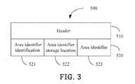
- FIG. 3is a schematic diagram of one embodiment of a transport control protocol (TCP) packet 500 used by the energy management device 110 in accordance with the present disclosure.
- the TCP packet 500may be the first multi-cast request transmitted from the energy management device 110 to the monitored area 200 , or a response transmitted from the monitored PLC modem 210 of the monitored area 200 to the energy management device 110 .
- the TCP packet 500includes a header field 510 and a data field 520 .
- the header field 510is set according to the TCP.
- the data field 520includes an area identifier identification field 521 , an area identifier storage location field 522 , and an area identifier field 523 .
- the area identifier identification field 521is used to inform the monitored area 200 to respond its area identifier to the energy management device 110
- the area identifier storage location field 522is used to inform the monitored area 200 to put its area identifier in the area identifier field 523 .
- the monitored PLC modem 210 of the monitored area 200parses the area identifier identification field 521 and the area identifier storage location field 522 of the first multi-cast request, and puts the area identifier of the monitored area 200 in the area identifier field 530 of a response, and transmits the response with the area identifier of the monitored area 200 to the energy management device 110 .
- FIG. 4is a flowchart of one embodiment of an energy management method in accordance with the present disclosure.
- the methodmay be embodied in the energy management device 110 , and is executed by the functional modules such as those of FIG. 1 .
- additional blocksmay be added, others deleted, and the ordering of the blocks may be changed while remaining well within the scope of the disclosure.
- the time control module 111determines whether a current time of each monitored area 200 is during a monitored time of the energy management device 110 .
- the data processing module 113acquires the area identifier and the body presence information from each monitored area 200 shown in block S 102 .
- the data processing module 113determines whether one or more monitored areas 200 are under control and without body presence according to the area identifier and the body presence information from each monitored area 200 .
- the data processing module 113transmits one or more power-off commands to turn off the monitored devices 230 located in the one or more monitored areas 200 , such that energy consumption is reduced.
Landscapes
- Engineering & Computer Science (AREA)
- Power Engineering (AREA)
- Computer Networks & Wireless Communication (AREA)
- General Engineering & Computer Science (AREA)
- Physics & Mathematics (AREA)
- General Physics & Mathematics (AREA)
- Automation & Control Theory (AREA)
- Signal Processing (AREA)
- Remote Monitoring And Control Of Power-Distribution Networks (AREA)
- Small-Scale Networks (AREA)
- Selective Calling Equipment (AREA)
Abstract
Description
Claims (8)
Applications Claiming Priority (3)
| Application Number | Priority Date | Filing Date | Title |
|---|---|---|---|
| CN201010274593.2ACN102403785B (en) | 2010-09-07 | 2010-09-07 | Power supply management device and power supply management method |
| CN201010274593 | 2010-09-07 | ||
| CN201010274593.2 | 2010-09-07 |
Publications (2)
| Publication Number | Publication Date |
|---|---|
| US20120059530A1 US20120059530A1 (en) | 2012-03-08 |
| US8467911B2true US8467911B2 (en) | 2013-06-18 |
Family
ID=45771289
Family Applications (1)
| Application Number | Title | Priority Date | Filing Date |
|---|---|---|---|
| US12/915,060Expired - Fee RelatedUS8467911B2 (en) | 2010-09-07 | 2010-10-29 | Energy management device and method |
Country Status (2)
| Country | Link |
|---|---|
| US (1) | US8467911B2 (en) |
| CN (1) | CN102403785B (en) |
Cited By (2)
| Publication number | Priority date | Publication date | Assignee | Title |
|---|---|---|---|---|
| US20150073568A1 (en)* | 2013-09-10 | 2015-03-12 | Kt Corporation | Controlling electronic devices based on footstep pattern |
| US9802789B2 (en) | 2013-10-28 | 2017-10-31 | Kt Corporation | Elevator security system |
Families Citing this family (12)
| Publication number | Priority date | Publication date | Assignee | Title |
|---|---|---|---|---|
| US10180713B2 (en) | 2012-08-28 | 2019-01-15 | BCP Controls, LLC | Method and system for utilizing proximity lighting and plug controls for real time location sensing |
| US9897989B2 (en) | 2012-08-28 | 2018-02-20 | BCP Controls, LLC | Method and system for utilizing a device's user location to monitor and control the device power usage |
| US9342125B1 (en) | 2012-08-28 | 2016-05-17 | BCP Controls, LLC | Method and system for utilizing a device's user location to monitor and control the device power usage |
| CN102932427B (en)* | 2012-09-29 | 2016-08-24 | 周万荣 | A kind of based on the control system limiting region |
| US10079506B2 (en) | 2013-01-18 | 2018-09-18 | Philips Lighting Holding B.V. | System and method for distribution of electrical power and control data in temporary lighting installations |
| CN104076754B (en)* | 2013-03-29 | 2017-02-08 | 鸿富锦精密工业(深圳)有限公司 | Power control device, system and method for controlling power on-off of power equipment |
| JP6190296B2 (en)* | 2014-03-13 | 2017-08-30 | アズビル株式会社 | Device management system, apparatus, and method |
| WO2016081511A2 (en)* | 2014-11-17 | 2016-05-26 | Curb Inc. | Managing resource consumption with device-specific notifications |
| JP6721677B2 (en)* | 2016-05-25 | 2020-07-15 | 株式会社東芝 | Energy management device, information device management device, management system, power consumption reduction method and program |
| JP7126187B2 (en)* | 2016-11-08 | 2022-08-26 | パナソニックIpマネジメント株式会社 | Information output system, equipment control system, information output method, and program |
| CN106707868B (en)* | 2016-12-30 | 2019-07-12 | 安徽朋德信息科技有限公司 | The power control method and power control system of shared laboratory apparatus |
| CN107168093A (en)* | 2017-07-18 | 2017-09-15 | 梧州井儿铺贸易有限公司 | A kind of intelligent home device regulator control system |
Citations (11)
| Publication number | Priority date | Publication date | Assignee | Title |
|---|---|---|---|---|
| US20020065583A1 (en)* | 2000-11-30 | 2002-05-30 | Matsushita Electric Works, Ltd. | Setting apparatus and setting method each for setting setting information in electric power line carrier communication terminal apparatus |
| US20040148632A1 (en)* | 2003-01-23 | 2004-07-29 | Ji-Hyun Park | Remote controller and set-top-box therefor |
| US20040257237A1 (en)* | 2003-02-24 | 2004-12-23 | George Bialecki | Room monitoring and lighting system |
| US20050009498A1 (en)* | 2003-07-07 | 2005-01-13 | Lg Electronics Inc. | Control system and method for home network system |
| US20050267605A1 (en)* | 2004-01-07 | 2005-12-01 | Lee Paul K | Home entertainment, security, surveillance, and automation control system |
| US7009348B2 (en)* | 2002-06-03 | 2006-03-07 | Systel Development & Industries Ltd. | Multiple channel ballast and networkable topology and system including power line carrier applications |
| US20080157938A1 (en)* | 2007-01-03 | 2008-07-03 | Sehat Sutardja | Time updating and load management systems |
| US7499978B2 (en)* | 2003-03-03 | 2009-03-03 | Lg Electronics Inc. | Apparatus for restoring network information for home network system and method thereof |
| US7504938B2 (en)* | 2005-07-15 | 2009-03-17 | Funai Electric Co., Ltd. | Security system and monitoring method using power line communication technology |
| US7813842B2 (en)* | 2006-03-09 | 2010-10-12 | Sony Corporation | Systems and methods for use in providing local power line communication |
| US8212883B2 (en)* | 2008-10-15 | 2012-07-03 | At&T Ip I, Lp | System and method for distributing video data over an electrical power line |
Family Cites Families (2)
| Publication number | Priority date | Publication date | Assignee | Title |
|---|---|---|---|---|
| CN1831717A (en)* | 2005-03-11 | 2006-09-13 | 广达电脑股份有限公司 | Power Saving and Security Method Applicable to Computer System |
| CN101458560B (en)* | 2008-12-25 | 2011-06-29 | 南京壹进制信息技术有限公司 | Computer intelligent energy-conserving method |
- 2010
- 2010-09-07CNCN201010274593.2Apatent/CN102403785B/ennot_activeExpired - Fee Related
- 2010-10-29USUS12/915,060patent/US8467911B2/ennot_activeExpired - Fee Related
Patent Citations (13)
| Publication number | Priority date | Publication date | Assignee | Title |
|---|---|---|---|---|
| US20020065583A1 (en)* | 2000-11-30 | 2002-05-30 | Matsushita Electric Works, Ltd. | Setting apparatus and setting method each for setting setting information in electric power line carrier communication terminal apparatus |
| US8036321B2 (en)* | 2002-06-03 | 2011-10-11 | S.T.L. Energy Solutions And Technologies Ltd. | Multiple channel ballast and networkable topology and system including power line carrier applications |
| US7009348B2 (en)* | 2002-06-03 | 2006-03-07 | Systel Development & Industries Ltd. | Multiple channel ballast and networkable topology and system including power line carrier applications |
| US7573372B2 (en)* | 2002-06-03 | 2009-08-11 | Systel Development & Industries Ltd. | Multiple channel ballast and networkable topology and system including power line carrier applications |
| US20040148632A1 (en)* | 2003-01-23 | 2004-07-29 | Ji-Hyun Park | Remote controller and set-top-box therefor |
| US20040257237A1 (en)* | 2003-02-24 | 2004-12-23 | George Bialecki | Room monitoring and lighting system |
| US7499978B2 (en)* | 2003-03-03 | 2009-03-03 | Lg Electronics Inc. | Apparatus for restoring network information for home network system and method thereof |
| US20050009498A1 (en)* | 2003-07-07 | 2005-01-13 | Lg Electronics Inc. | Control system and method for home network system |
| US20050267605A1 (en)* | 2004-01-07 | 2005-12-01 | Lee Paul K | Home entertainment, security, surveillance, and automation control system |
| US7504938B2 (en)* | 2005-07-15 | 2009-03-17 | Funai Electric Co., Ltd. | Security system and monitoring method using power line communication technology |
| US7813842B2 (en)* | 2006-03-09 | 2010-10-12 | Sony Corporation | Systems and methods for use in providing local power line communication |
| US20080157938A1 (en)* | 2007-01-03 | 2008-07-03 | Sehat Sutardja | Time updating and load management systems |
| US8212883B2 (en)* | 2008-10-15 | 2012-07-03 | At&T Ip I, Lp | System and method for distributing video data over an electrical power line |
Cited By (3)
| Publication number | Priority date | Publication date | Assignee | Title |
|---|---|---|---|---|
| US20150073568A1 (en)* | 2013-09-10 | 2015-03-12 | Kt Corporation | Controlling electronic devices based on footstep pattern |
| US10203669B2 (en)* | 2013-09-10 | 2019-02-12 | Kt Corporation | Controlling electronic devices based on footstep pattern |
| US9802789B2 (en) | 2013-10-28 | 2017-10-31 | Kt Corporation | Elevator security system |
Also Published As
| Publication number | Publication date |
|---|---|
| CN102403785B (en) | 2014-07-16 |
| US20120059530A1 (en) | 2012-03-08 |
| CN102403785A (en) | 2012-04-04 |
Similar Documents
| Publication | Publication Date | Title |
|---|---|---|
| US8467911B2 (en) | Energy management device and method | |
| CN109450704B (en) | A plug-and-play intelligent distribution transformer terminal and distribution data communication system | |
| US9198217B2 (en) | Method for maintaining connection between terminal and network server, terminal and network server | |
| WO2022001674A1 (en) | Communication system, method and device for miniature intelligent sensor | |
| CN108012312B (en) | Paged device, paging device and method | |
| US20110264294A1 (en) | Set-top box and energy management method | |
| CN105005201A (en) | Multi-mobile-terminal data synchronization and push system for intelligent household | |
| CN103857072A (en) | Home gateway device based on zigbee and wifi networks | |
| CN104267701B (en) | The control method and device of smart home newly added equipment | |
| CN107484232A (en) | Message method, system, the network equipment and readable storage medium storing program for executing | |
| CN108449246A (en) | A kind of intelligent domestic system based on instant message applications Yu Internet of Things Network Communication | |
| CN105262599B (en) | A remote power control system based on WiFi | |
| CN111935517B (en) | Awakening method and device of intelligent set top box, electronic equipment and storage medium | |
| CN106330632A (en) | Intelligent home Internet of Things communication device | |
| CN106066658B (en) | Internet of things intelligent household temperature control system | |
| CN104113560A (en) | Intelligent household security monitoring system based on internet of things technology | |
| CN103888556A (en) | Home terminal device and home terminal device control method | |
| CN109327560A (en) | IP address re-rents method, apparatus, network system and electronic equipment | |
| CN106027347A (en) | Embedded smart gateway device applicable to smart home system and application method thereof | |
| CN202551356U (en) | IOT (Internet Of Things) access transmission module | |
| CN214901321U (en) | Lock networking system based on Bluetooth router and lock networking system applied to hotel | |
| Li et al. | Development of mobile application for smart home energy management: iSHome | |
| TWI416837B (en) | Power management device and method therefor | |
| CN203311249U (en) | Network center computer room cloud-monitoring system | |
| JP2010109928A (en) | Repeater |
Legal Events
| Date | Code | Title | Description |
|---|---|---|---|
| AS | Assignment | Owner name:HONG FU JIN PRECISION INDUSTRY (SHENZHEN) CO., LTD Free format text:ASSIGNMENT OF ASSIGNORS INTEREST;ASSIGNORS:LUO, YI;DING, SHANG-JUE;REEL/FRAME:025223/0714 Effective date:20101028 Owner name:HON HAI PRECISION INDUSTRY CO., LTD., TAIWAN Free format text:ASSIGNMENT OF ASSIGNORS INTEREST;ASSIGNORS:LUO, YI;DING, SHANG-JUE;REEL/FRAME:025223/0714 Effective date:20101028 | |
| STCF | Information on status: patent grant | Free format text:PATENTED CASE | |
| FPAY | Fee payment | Year of fee payment:4 | |
| AS | Assignment | Owner name:NANNING FUGUI PRECISION INDUSTRIAL CO., LTD., CHIN Free format text:ASSIGNMENT OF ASSIGNORS INTEREST;ASSIGNORS:HONG FU JIN PRECISION INDUSTRY (SHENZHEN) CO., LTD.;HON HAI PRECISION INDUSTRY CO., LTD.;REEL/FRAME:045171/0433 Effective date:20171229 | |
| FEPP | Fee payment procedure | Free format text:MAINTENANCE FEE REMINDER MAILED (ORIGINAL EVENT CODE: REM.); ENTITY STATUS OF PATENT OWNER: LARGE ENTITY | |
| LAPS | Lapse for failure to pay maintenance fees | Free format text:PATENT EXPIRED FOR FAILURE TO PAY MAINTENANCE FEES (ORIGINAL EVENT CODE: EXP.); ENTITY STATUS OF PATENT OWNER: LARGE ENTITY | |
| STCH | Information on status: patent discontinuation | Free format text:PATENT EXPIRED DUE TO NONPAYMENT OF MAINTENANCE FEES UNDER 37 CFR 1.362 | |
| FP | Lapsed due to failure to pay maintenance fee | Effective date:20210618 |