US8467540B2 - Electronic device and method thereof for switching audio input channel of the electronic device - Google Patents
Electronic device and method thereof for switching audio input channel of the electronic deviceDownload PDFInfo
- Publication number
- US8467540B2 US8467540B2US12/826,677US82667710AUS8467540B2US 8467540 B2US8467540 B2US 8467540B2US 82667710 AUS82667710 AUS 82667710AUS 8467540 B2US8467540 B2US 8467540B2
- Authority
- US
- United States
- Prior art keywords
- level
- headphone
- electronic device
- input channel
- audio input
- Prior art date
- Legal status (The legal status is an assumption and is not a legal conclusion. Google has not performed a legal analysis and makes no representation as to the accuracy of the status listed.)
- Expired - Fee Related, expires
Links
Images


Classifications
- H—ELECTRICITY
- H04—ELECTRIC COMMUNICATION TECHNIQUE
- H04B—TRANSMISSION
- H04B3/00—Line transmission systems
- H—ELECTRICITY
- H04—ELECTRIC COMMUNICATION TECHNIQUE
- H04R—LOUDSPEAKERS, MICROPHONES, GRAMOPHONE PICK-UPS OR LIKE ACOUSTIC ELECTROMECHANICAL TRANSDUCERS; DEAF-AID SETS; PUBLIC ADDRESS SYSTEMS
- H04R1/00—Details of transducers, loudspeakers or microphones
- H04R1/10—Earpieces; Attachments therefor ; Earphones; Monophonic headphones
- H04R1/1041—Mechanical or electronic switches, or control elements
- H—ELECTRICITY
- H04—ELECTRIC COMMUNICATION TECHNIQUE
- H04R—LOUDSPEAKERS, MICROPHONES, GRAMOPHONE PICK-UPS OR LIKE ACOUSTIC ELECTROMECHANICAL TRANSDUCERS; DEAF-AID SETS; PUBLIC ADDRESS SYSTEMS
- H04R5/00—Stereophonic arrangements
- H04R5/033—Headphones for stereophonic communication
- H—ELECTRICITY
- H04—ELECTRIC COMMUNICATION TECHNIQUE
- H04R—LOUDSPEAKERS, MICROPHONES, GRAMOPHONE PICK-UPS OR LIKE ACOUSTIC ELECTROMECHANICAL TRANSDUCERS; DEAF-AID SETS; PUBLIC ADDRESS SYSTEMS
- H04R5/00—Stereophonic arrangements
- H04R5/04—Circuit arrangements, e.g. for selective connection of amplifier inputs/outputs to loudspeakers, for loudspeaker detection, or for adaptation of settings to personal preferences or hearing impairments
- H—ELECTRICITY
- H04—ELECTRIC COMMUNICATION TECHNIQUE
- H04R—LOUDSPEAKERS, MICROPHONES, GRAMOPHONE PICK-UPS OR LIKE ACOUSTIC ELECTROMECHANICAL TRANSDUCERS; DEAF-AID SETS; PUBLIC ADDRESS SYSTEMS
- H04R2420/00—Details of connection covered by H04R, not provided for in its groups
- H04R2420/01—Input selection or mixing for amplifiers or loudspeakers
- H—ELECTRICITY
- H04—ELECTRIC COMMUNICATION TECHNIQUE
- H04R—LOUDSPEAKERS, MICROPHONES, GRAMOPHONE PICK-UPS OR LIKE ACOUSTIC ELECTROMECHANICAL TRANSDUCERS; DEAF-AID SETS; PUBLIC ADDRESS SYSTEMS
- H04R2420/00—Details of connection covered by H04R, not provided for in its groups
- H04R2420/05—Detection of connection of loudspeakers or headphones to amplifiers
Definitions
- the present disclosurerelates to an electronic device and a method thereof for switching an audio input channel of the electronic device.
- Electronic devicessuch as mobile phones, personal digital assistants (PDAs), digital still cameras (DSCs), and others, supporting audio input and output, are widely used.
- PDAspersonal digital assistants
- DSCsdigital still cameras
- two types of headphonesare suitable for the electronic device.
- One type of headphonehas no microphone and only supports audio output.
- the other type of headphonecombines with the microphone, so-called headset, and supports both the audio input and output.
- the audio input and output of the electronic deviceare still assigned to the headphone having no microphone when the headphone having no microphone is inserted into the electronic device.
- the audio inputis unacceptably disable.
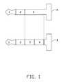
- FIG. 1shows an exemplary embodiment of audio connectors of two types of headphones.
- FIG. 2is a block diagram of one embodiment of an electronic device.
- FIG. 3is an exemplary diagram showing four operating states of the present disclosure.
- FIG. 4is a flowchart illustrating one embodiment of a method for switching an audio input channel of an electronic device.
- unit and modulerefers to logic embodied in hardware or firmware, or to a collection of software instructions, written in a programming language, such as, for example, Java, C, or assembly.
- One or more software instructions in the unitmay be integrated in firmware, such as an EPROM.
- modulemay comprise connected logic units, such as gates and flip-flops, and may comprise programmable units, such as programmable gate arrays or processors.
- the unit described hereinmay be implemented as either software and/or hardware unit and may be stored in any type of computer-readable medium or other computer storage device.
- FIG. 1shows an exemplary embodiment of two types of audio connectors of a headphone.
- the audio connectorsare operable to connect with electronic devices.
- the audio connector of the headphone having no microphoneis an audio jack A.
- a first pole of the audio jack Ais operable to transmit a left channel of an audio signal.
- a second pole of the audio jack Ais operable to transmit a right channel of the audio signal.
- a third pole of the audio jack Ais operable to connect to ground.
- the audio connector of a headsetcomprising a headphone with a microphone and a control button, is an audio jack B.
- the first pole of the audio jack Bis operable to transmit the left channel of the audio signal.
- the second pole of the audio jack Bis operable to transmit the right channel of the audio signal.
- the third pole of the audio jack Bis operable to connect to ground.
- a fourth pole of the audio jack Bis operable to transmit an audio input signal of the microphone and a button signal of the control button.
- the sum of the lengths of the third and fourth poles of the audio jack Bis equal to the length of the third pole of the audio jack A.
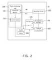
- FIG. 2is a block diagram of one embodiment of an electronic device 10 .
- the electronic device 10includes a headphone interface 20 , a signal processing unit 100 , a detection circuit 103 , an internal microphone 104 , a multiplexer 105 , and an audio processing unit 106 .
- the electronic device 10is operable to switch the audio input channel based on different types of audio connectors connected with the electronic device.
- the electronic device 10is generally controlled and coordinated by an operating system, such as UNIX, Linux, Windows, Mac OS, an embedded operating, or any other compatible system. Alternatively, the electronic device 10 may be controlled by a proprietary operating system. Typical operating systems control and schedule computer processes for execution, perform memory management, provide file system, networking, and I/O services, and provide a user interface, such as a graphical user interface (GUI), among other tasks.
- an operating systemsuch as UNIX, Linux, Windows, Mac OS, an embedded operating, or any other compatible system.
- Typical operating systemscontrol and schedule computer processes for execution, perform memory management, provide file system, networking, and I/O services, and provide a user interface, such as a graphical user interface (GUI), among other tasks.
- GUIgraphical user interface
- the headphone interface 20is operable to connect with the audio connector of the headphone.
- the detection circuit 103includes a headphone pin HD and a button pin PTT.
- the detection circuit 103is operable to detect a level of a last pole of the audio connector, transfer the level of the last pole into a first level of the headphone pin HD and a second level of the button pin PTT, and output the first level and the second level to the signal processing unit 100 .
- the last pole of the audio connectorrepresents the third pole of the audio jack A, or the fourth pole of the audio jack B.
- the microphone of the headphoneis disabled when the control button is pressed, such that the audio signal is merely inputted into the electronic device through the internal microphone 104 .
- the signal processing unit 100includes an acquisition module 101 and a control module 102 .
- the acquisition module 101is operable to receive the first level and the second level from the headphone pin HD and the button pin PTT of the detection circuit 103 .
- the acquisition module 101further determines whether the first level is the same as the second level and outputs the result to the control module 102 .
- the control module 102is operable to control the multiplexer 105 to switch the audio input channel of the electronic device in response to the first level and the second level.
- the control module 102is further operable to transmit a first command to the multiplexer 105 if the first level is the same as the second level, and transmit a second command to the multiplexer 105 if the first level is different from the second level.
- the multiplexer 105is further operable to set a first input of the internal microphone 104 as the audio input channel based on the first command, and set a second input of the headphone interface 20 as the audio input channel based on the second command.
- the audio processing circuit 106is operable to process the audio signal from the audio input channel.
- the audio processing circuit 106electronically connects with internal microphone 104 through the multiplexer 105 when the first input is set as the audio input channel.
- the audio processing circuit 106electronically connects with headphone interface 20 through the multiplexer 105 when the second input is set as the audio input channel.
- FIG. 3is a diagram showing four operating states of the present disclosure.
- the operating stateis changed from the first state to the second state.
- the operating statechanges from the first state to the third state.
- the electronic device 10determines the operating state is the second state. Once the control button is released, the electronic device 10 transfers the operating state from the second state to the fourth state.
- FIG. 4is a flowchart illustrating one embodiment of a method for switching the audio input channel of the electronic device 10 .
- additional blocks in the flow of FIG. 4may be added, others removed, and the ordering of the blocks may be changed.
- the detection circuit 103detects the level of the last pole of the headphone connecting with the headphone interface 20 .
- the detection circuit 103transfers the level of the last pole into the first level of the headphone pin HD and the second level of the button pin PTT.
- the detection circuit 103outputs the first level and the second level to the acquisition module 101 .
- the acquisition module 101determines whether the first level is the same as the second level and outputs the result to the control module 102 .
- the control module 102transmits the first command to the multiplexer 105 .
- the multiplexer 105sets the first input of the internal microphone 104 as the audio input channel based on the first command.
- control module 102transmits the second command to the multiplexer 105 .
- the multiplexer 105sets the second input of the headphone interface 20 as the audio input channel based on the second command.
- the present disclosureprovides a method for efficiently switching audio input channels of an electronic device when a headphone or headset is connected.
Landscapes
- Engineering & Computer Science (AREA)
- Signal Processing (AREA)
- Physics & Mathematics (AREA)
- Acoustics & Sound (AREA)
- Computer Networks & Wireless Communication (AREA)
- Circuit For Audible Band Transducer (AREA)
- Headphones And Earphones (AREA)
Abstract
Description
Claims (12)
Applications Claiming Priority (3)
| Application Number | Priority Date | Filing Date | Title |
|---|---|---|---|
| CN201010301150.8 | 2010-02-03 | ||
| CN201010301150 | 2010-02-03 | ||
| CN201010301150.8ACN102143262B (en) | 2010-02-03 | 2010-02-03 | Electronic device and method for switching audio input channel thereof |
Publications (2)
| Publication Number | Publication Date |
|---|---|
| US20110188669A1 US20110188669A1 (en) | 2011-08-04 |
| US8467540B2true US8467540B2 (en) | 2013-06-18 |
Family
ID=44341667
Family Applications (1)
| Application Number | Title | Priority Date | Filing Date |
|---|---|---|---|
| US12/826,677Expired - Fee RelatedUS8467540B2 (en) | 2010-02-03 | 2010-06-30 | Electronic device and method thereof for switching audio input channel of the electronic device |
Country Status (2)
| Country | Link |
|---|---|
| US (1) | US8467540B2 (en) |
| CN (1) | CN102143262B (en) |
Cited By (1)
| Publication number | Priority date | Publication date | Assignee | Title |
|---|---|---|---|---|
| US9678909B1 (en) | 2016-05-19 | 2017-06-13 | Motorola Solutions, Inc. | Methods and systems of exchanging data between an electronic device and an external accessory |
Families Citing this family (23)
| Publication number | Priority date | Publication date | Assignee | Title |
|---|---|---|---|---|
| KR101646964B1 (en)* | 2009-10-14 | 2016-08-09 | 삼성전자주식회사 | Circuit apparatus and method for recognition earphone in electronic device |
| CN101980513A (en)* | 2010-08-05 | 2011-02-23 | 上海闻泰电子科技有限公司 | Mobile phone with anti-wiretapping function and anti-wiretapping implementation method for same |
| KR101469545B1 (en)* | 2011-09-06 | 2014-12-05 | 삼성전자주식회사 | Method for processing and audio signal and apparatus for processing an audio signal thereof |
| CN102544953B (en)* | 2011-12-06 | 2014-07-30 | 深圳市文鼎创数据科技有限公司 | Self-adaptive audio frequency switching device and method |
| US20130232282A1 (en) | 2012-03-05 | 2013-09-05 | Jihwan Kim | Electronic device and method of controlling the same |
| CA2869856C (en) | 2012-04-13 | 2017-07-11 | Twisted Pair Solutions, Inc. | Pulsed input push-to-talk systems, methods and apparatus |
| CN103379420B (en)* | 2012-04-18 | 2016-10-05 | 华为终端有限公司 | A kind of method determining earphone line sequence and electronic equipment |
| CN103916151B (en)* | 2012-12-30 | 2016-03-30 | 北京握奇数据系统有限公司 | A kind of methods, devices and systems obtaining tone frequency channel wire sequence |
| US10043535B2 (en) | 2013-01-15 | 2018-08-07 | Staton Techiya, Llc | Method and device for spectral expansion for an audio signal |
| CN103327433B (en)* | 2013-05-27 | 2014-08-27 | 腾讯科技(深圳)有限公司 | Audio input interface detection method and system thereof |
| US9210555B2 (en) | 2013-10-15 | 2015-12-08 | Twisted Pair Solutions, Inc. | Pulsed input push-to-talk wireless adapter systems and methods |
| US10045135B2 (en) | 2013-10-24 | 2018-08-07 | Staton Techiya, Llc | Method and device for recognition and arbitration of an input connection |
| US10043534B2 (en) | 2013-12-23 | 2018-08-07 | Staton Techiya, Llc | Method and device for spectral expansion for an audio signal |
| TWI559783B (en)* | 2015-03-13 | 2016-11-21 | 華碩電腦股份有限公司 | Sound interface circuit |
| CN106412760B (en)* | 2015-07-30 | 2019-02-01 | 成都鼎桥通信技术有限公司 | Earphone compatible device |
| CN105554631B (en)* | 2015-12-22 | 2019-06-28 | 小米科技有限责任公司 | Audio switching method, device and electronic equipment |
| CN207010908U (en)* | 2016-07-20 | 2018-02-13 | 中兴通讯股份有限公司 | Terminal and earphone |
| CN106254993B (en)* | 2016-09-27 | 2019-09-10 | 依偎科技(南昌)有限公司 | A kind of earphone left and right acoustic channels self-adaptation control method and device |
| CN108769847A (en)* | 2018-08-20 | 2018-11-06 | 深圳市爱图仕影像器材有限公司 | A kind of microphone and implementation method with intelligent conversion interface |
| CN111200767B (en)* | 2018-11-20 | 2022-06-03 | 成都鼎桥通信技术有限公司 | Earphone detection method, earphone detection device, terminal and storage medium |
| CN111245696B (en)* | 2019-12-23 | 2021-06-29 | 上海微波技术研究所(中国电子科技集团公司第五十研究所) | Device and method for improving command communication capability in high-noise environment in vehicle |
| CN112738307B (en)* | 2020-12-29 | 2023-02-24 | 维沃移动通信有限公司 | Electronic equipment |
| CN116261081B (en)* | 2023-05-16 | 2023-08-01 | 合肥联宝信息技术有限公司 | Headphone circuit and control method thereof |
Citations (9)
| Publication number | Priority date | Publication date | Assignee | Title |
|---|---|---|---|---|
| US20050201568A1 (en)* | 2004-03-11 | 2005-09-15 | Texas Instruments Incorporated | Headset Detector in a Device Generating Audio Signals |
| CN101198192A (en) | 2006-12-08 | 2008-06-11 | 启碁科技股份有限公司 | Electronic device capable of automatically judging earphone type and related method thereof |
| CN201349247Y (en) | 2008-12-22 | 2009-11-18 | 宇龙计算机通信科技(深圳)有限公司 | Earphone interface circuit and movable termination |
| US20090296952A1 (en)* | 2008-05-30 | 2009-12-03 | Achim Pantfoerder | Headset microphone type detect |
| US7836216B2 (en)* | 2005-08-23 | 2010-11-16 | Palm, Inc. | Connector system for supporting multiple types of plug carrying accessory devices |
| US7869608B2 (en)* | 2008-01-14 | 2011-01-11 | Apple Inc. | Electronic device accessory |
| US7912501B2 (en)* | 2007-01-05 | 2011-03-22 | Apple Inc. | Audio I/O headset plug and plug detection circuitry |
| US8155337B2 (en)* | 2007-11-28 | 2012-04-10 | Samsung Electronics Co., Ltd | Compatible circuit and method for 4- and 5-pole earphones and portable device using the same |
| US8180397B2 (en)* | 2009-10-28 | 2012-05-15 | Research In Motion Limited | Mobile communications device accessory identification system, an improved accessory for use with a mobile communications device, and a method of identifying same |
Family Cites Families (1)
| Publication number | Priority date | Publication date | Assignee | Title |
|---|---|---|---|---|
| CN201142743Y (en)* | 2007-12-08 | 2008-10-29 | 青岛海信移动通信技术股份有限公司 | Headphone interface circuit and mobile phone with the same |
- 2010
- 2010-02-03CNCN201010301150.8Apatent/CN102143262B/enactiveActive
- 2010-06-30USUS12/826,677patent/US8467540B2/ennot_activeExpired - Fee Related
Patent Citations (9)
| Publication number | Priority date | Publication date | Assignee | Title |
|---|---|---|---|---|
| US20050201568A1 (en)* | 2004-03-11 | 2005-09-15 | Texas Instruments Incorporated | Headset Detector in a Device Generating Audio Signals |
| US7836216B2 (en)* | 2005-08-23 | 2010-11-16 | Palm, Inc. | Connector system for supporting multiple types of plug carrying accessory devices |
| CN101198192A (en) | 2006-12-08 | 2008-06-11 | 启碁科技股份有限公司 | Electronic device capable of automatically judging earphone type and related method thereof |
| US7912501B2 (en)* | 2007-01-05 | 2011-03-22 | Apple Inc. | Audio I/O headset plug and plug detection circuitry |
| US8155337B2 (en)* | 2007-11-28 | 2012-04-10 | Samsung Electronics Co., Ltd | Compatible circuit and method for 4- and 5-pole earphones and portable device using the same |
| US7869608B2 (en)* | 2008-01-14 | 2011-01-11 | Apple Inc. | Electronic device accessory |
| US20090296952A1 (en)* | 2008-05-30 | 2009-12-03 | Achim Pantfoerder | Headset microphone type detect |
| CN201349247Y (en) | 2008-12-22 | 2009-11-18 | 宇龙计算机通信科技(深圳)有限公司 | Earphone interface circuit and movable termination |
| US8180397B2 (en)* | 2009-10-28 | 2012-05-15 | Research In Motion Limited | Mobile communications device accessory identification system, an improved accessory for use with a mobile communications device, and a method of identifying same |
Cited By (1)
| Publication number | Priority date | Publication date | Assignee | Title |
|---|---|---|---|---|
| US9678909B1 (en) | 2016-05-19 | 2017-06-13 | Motorola Solutions, Inc. | Methods and systems of exchanging data between an electronic device and an external accessory |
Also Published As
| Publication number | Publication date |
|---|---|
| CN102143262A (en) | 2011-08-03 |
| US20110188669A1 (en) | 2011-08-04 |
| CN102143262B (en) | 2014-03-26 |
Similar Documents
| Publication | Publication Date | Title |
|---|---|---|
| US8467540B2 (en) | Electronic device and method thereof for switching audio input channel of the electronic device | |
| US11985464B2 (en) | Wireless audio output devices | |
| US11129221B2 (en) | Bluetooth connection method, device and smart terminal | |
| EP3822801B1 (en) | Method and apparatus for providing interface | |
| CN108540193B (en) | Front-end module and electronics supporting device-to-device communication using multiple frequency bands | |
| US9749730B2 (en) | Method for processing data and electronic device therefor | |
| JP7462657B2 (en) | Method for transmitting indication signal, terminal and network device | |
| US20130101132A1 (en) | Method and Device for Earphone and USB to Share Micro-USB Interface | |
| CN113194450B (en) | Bluetooth device management method and device | |
| US9749748B2 (en) | Electronic device and method for detecting plug type of audio device inserted into electronic device | |
| EP3644671A1 (en) | Method and device for indicating radio bearer | |
| CN106463897B (en) | Apparatus and method for preventing malfunctions in electronic equipment | |
| CN110958662B (en) | An access control method, terminal and network side equipment | |
| KR20120084666A (en) | Apparatus and method for switching multi-channel audio in a portable terminal | |
| KR20180123879A (en) | Electronic device and method for controlling audio output according to type of earphone | |
| WO2021047116A1 (en) | Wireless earphone synchronization detection method, apparatus, wireless earphones and storage medium | |
| US9621986B2 (en) | Electronic device, audio device, and method for supplying power to the audio device | |
| CN114374959B (en) | Bluetooth connection method, device, electronic device and storage medium | |
| CN105323680A (en) | audio device | |
| CN110879792A (en) | Electronic device and interface control method thereof | |
| US20160253273A1 (en) | Hub, operation system, and control method thereof | |
| US8407390B2 (en) | Method and apparatus for data processing | |
| CN104461952A (en) | An interface sharing method and terminal | |
| KR102240526B1 (en) | Contents download method of electronic apparatus and electronic appparatus thereof | |
| CN116054870A (en) | Wireless communication circuit, bluetooth communication switching method and electronic equipment |
Legal Events
| Date | Code | Title | Description |
|---|---|---|---|
| AS | Assignment | Owner name:FOXCONN COMMUNICATION TECHNOLOGY CORP., TAIWAN Free format text:ASSIGNMENT OF ASSIGNORS INTEREST;ASSIGNOR:LU, YEN-KUANG;REEL/FRAME:024613/0641 Effective date:20100608 | |
| AS | Assignment | Owner name:FIH (HONG KONG) LIMITED, HONG KONG Free format text:ASSIGNMENT OF ASSIGNORS INTEREST;ASSIGNOR:FOXCONN COMMUNICATION TECHNOLOGY CORP.;REEL/FRAME:028439/0786 Effective date:20120605 | |
| STCF | Information on status: patent grant | Free format text:PATENTED CASE | |
| FPAY | Fee payment | Year of fee payment:4 | |
| MAFP | Maintenance fee payment | Free format text:PAYMENT OF MAINTENANCE FEE, 8TH YEAR, LARGE ENTITY (ORIGINAL EVENT CODE: M1552); ENTITY STATUS OF PATENT OWNER: LARGE ENTITY Year of fee payment:8 | |
| FEPP | Fee payment procedure | Free format text:MAINTENANCE FEE REMINDER MAILED (ORIGINAL EVENT CODE: REM.); ENTITY STATUS OF PATENT OWNER: LARGE ENTITY | |
| LAPS | Lapse for failure to pay maintenance fees | Free format text:PATENT EXPIRED FOR FAILURE TO PAY MAINTENANCE FEES (ORIGINAL EVENT CODE: EXP.); ENTITY STATUS OF PATENT OWNER: LARGE ENTITY | |
| STCH | Information on status: patent discontinuation | Free format text:PATENT EXPIRED DUE TO NONPAYMENT OF MAINTENANCE FEES UNDER 37 CFR 1.362 | |
| FP | Lapsed due to failure to pay maintenance fee | Effective date:20250618 |