US8467175B2 - System and method for an optimizable rack solution - Google Patents
System and method for an optimizable rack solutionDownload PDFInfo
- Publication number
- US8467175B2 US8467175B2US13/022,211US201113022211AUS8467175B2US 8467175 B2US8467175 B2US 8467175B2US 201113022211 AUS201113022211 AUS 201113022211AUS 8467175 B2US8467175 B2US 8467175B2
- Authority
- US
- United States
- Prior art keywords
- rack
- frame
- space
- optimizable
- primary
- Prior art date
- Legal status (The legal status is an assumption and is not a legal conclusion. Google has not performed a legal analysis and makes no representation as to the accuracy of the status listed.)
- Active, expires
Links
Images


Classifications
- G—PHYSICS
- G06—COMPUTING OR CALCULATING; COUNTING
- G06F—ELECTRIC DIGITAL DATA PROCESSING
- G06F1/00—Details not covered by groups G06F3/00 - G06F13/00 and G06F21/00
- G06F1/16—Constructional details or arrangements
- G06F1/1601—Constructional details related to the housing of computer displays, e.g. of CRT monitors, of flat displays
- H—ELECTRICITY
- H05—ELECTRIC TECHNIQUES NOT OTHERWISE PROVIDED FOR
- H05K—PRINTED CIRCUITS; CASINGS OR CONSTRUCTIONAL DETAILS OF ELECTRIC APPARATUS; MANUFACTURE OF ASSEMBLAGES OF ELECTRICAL COMPONENTS
- H05K7/00—Constructional details common to different types of electric apparatus
- H05K7/14—Mounting supporting structure in casing or on frame or rack
- H05K7/1485—Servers; Data center rooms, e.g. 19-inch computer racks
- H05K7/1488—Cabinets therefor, e.g. chassis or racks or mechanical interfaces between blades and support structures
- H05K7/1492—Cabinets therefor, e.g. chassis or racks or mechanical interfaces between blades and support structures having electrical distribution arrangements, e.g. power supply or data communications
- H—ELECTRICITY
- H05—ELECTRIC TECHNIQUES NOT OTHERWISE PROVIDED FOR
- H05K—PRINTED CIRCUITS; CASINGS OR CONSTRUCTIONAL DETAILS OF ELECTRIC APPARATUS; MANUFACTURE OF ASSEMBLAGES OF ELECTRICAL COMPONENTS
- H05K7/00—Constructional details common to different types of electric apparatus
- H05K7/14—Mounting supporting structure in casing or on frame or rack
- H05K7/1485—Servers; Data center rooms, e.g. 19-inch computer racks
- H05K7/1498—Resource management, Optimisation arrangements, e.g. configuration, identification, tracking, physical location
Definitions
- the present disclosurerelates generally to the operation of computer systems and information handling systems, and, more particularly, to a system and method for an optimizable rack solution.
- An information handling systemgenerally processes, compiles, stores, and/or communicates information or data for business, personal, or other purposes thereby allowing users to take advantage of the value of the information. Because technology and information handling needs and requirements vary between different users or applications, information handling systems may vary with respect to the type of information handled; the methods for handling the information; the methods for processing, storing or communicating the information; the amount of information processed, stored, or communicated; and the speed and efficiency with which the information is processed, stored, or communicated.
- information handling systemsallow for information handling systems to be general or configured for a specific user or specific use such as financial transaction processing, airline reservations, enterprise data storage, or global communications.
- information handling systemsmay include or comprise a variety of hardware and software components that may be configured to process, store, and communicate information and may include one or more computer systems, data storage systems, and networking systems.
- Information handling systemsare commonly designed for mounting in racks. Data centers typically require numerous racks populated with many information handling systems to provide the necessary computing power.
- the most common type of information handling system to be included in a data centeris a standard 19-inch wide server, which is widely available and generally interchangeable across brands.
- the height of the standard 19-inch wide serverdepends on the server design, but is measured in terms of rack units, or “U”, where one U is approximately 1.75 inches.
- the standard 19-inch serversare typically housed in standard racks, which generally include a box-like frame in which the standard servers are mounted horizontally in a vertically stacked arrangement. The equipment capacity of a standard rack thus depends on the height of the rack, and standard racks typically hold 42 U worth of standard 19-inch servers.
- Standard racksare beneficial because they are widely available.
- One problem with standard racksis that they have a fixed structure, which fixes the footprint and the capacity of the rack. This is particularly problematic where space and computing density are primary concerns, such as in a containerized data center, which is typically constructed in a shipping container.
- space and computing densityare primary concerns, such as in a containerized data center, which is typically constructed in a shipping container.
- fully populating a containerized data centers with standard racksmay not provide the necessary computing density, and standard racks cannot be optimized to increase the density.
- the structure of the standard rackgenerally cannot be optimized for design concerns prevalent in a containerized data center, where space is at a premium, such as how to integrate the rack within a containerized data center and how to account for the power and cooling needs of the information handling systems within the rack.
- a system and method for an optimizable rack solutionis presented.
- the system and methodis directed to an optimizable rack that includes a frame.
- the framehas both a primary portion and a detachable portion.
- the primary portionmay contain a primary enclosure and the detachable portion may container a secondary enclosure.
- Each of the primary enclosure and secondary enclosureare sized to hold a plurality of computing systems. Detaching the detachable portion of the frame both reduces the size and computing systems capacity of the frame.
- the system and method disclosed hereinis technically advantageous because it provides a system and method for a rack that can be optimized for a given solution.
- the size and computing system capacitycan be optimized according to space limitations in a data center.
- the optimizable rackmay offer computing systems capacity that is higher than a standard server.
- the computing system density of the optimized rackmay be higher than that of a standard server, because the floorspace occupied by the optimized rack may be narrowed.
- the optimizable rackis beneficial because it can be sized to fit standard 19-inch wide servers, meaning that the capacity and density of computing systems within a data center can be increased, without requiring proprietary or custom sized computing solutions.
- the rackis optimizable, it can be optimized for a variety of different data centers, including modular data centers, and the frame of the optimizable rack may be optimized to include mounting and integration elements.
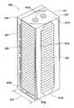
- FIG. 1is one example of a prior art standard rack.
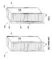
- FIG. 2is one embodiment of an optimizable rack according to one aspect of the present invention.
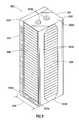
- FIG. 3is another embodiment of an optimizable rack according to aspects of the present invention.
- FIG. 4is another embodiment of an optimizable rack according to aspects of the present invention.
- FIG. 5is a preferred embodiment of an optimizable rack according to aspects of the present invention.
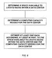
- FIG. 6is a flow diagram for a method of optimizing a modular data center according to aspect of the present invention.
- FIG. 7is a flow diagram of a preferred method of optimizing a modular data center according to aspects of the present invention.
- an information handling systemmay include any instrumentality or aggregate of instrumentalities operable to compute, classify, process, transmit, receive, retrieve, originate, switch, store, display, manifest, detect, record, reproduce, handle, or utilize any form of information, intelligence, or data for business, scientific, control, or other purposes.
- an information handling systemmay be a personal computer, a network storage device, or any other suitable device and may vary in size, shape, performance, functionality, and price.
- the information handling systemmay include random access memory (RAM), one or more processing resources such as a central processing unit (CPU) or hardware or software control logic, ROM, and/or other types of nonvolatile memory.
- Additional components of the information handling systemmay include one or more disk drives, one or more network ports for communication with external devices as well as various input and output (I/O) devices, such as a keyboard, a mouse, and a video display.
- the information handling systemmay also include one or more buses operable to transmit communications between the various hardware components.
- the standard rack 100includes a frame 101 , a rectangular cuboid, with an outside width 102 of approximately 24 inches.
- the frame 101includes an enclosure 103 , which is approximately 19 inches wide.
- Standard 19-inch servers 104may be inserted into the enclosure 103 and mounted in the standard rack 100 , as shown.
- the standard 19-inch servers 104are each 2 U tall. As can be seen, there are 21 of the standard 19-inch servers 104 , meaning that the computing capacity of standard rack 100 is 42 U, as is typical. Stated another way, the enclosure 103 is 42 U tall. As can also be seen, the standard 19-inch servers 104 do not fill the entire 24 inch width of the standard rack 100 .
- zero U spacethere is a similarly sized space on both sides of the standard 19-inch servers called “zero U” space, which is defined by the sides of the standard 19-inch servers and the frame 101 .
- This spaceis problematic in limited space environments, because it wastes space within footprint of the standard rack. Utilizing and/or minimizing this “zero U” space is one benefit of the present invention.
- FIG. 2is an optimizable rack 200 according to one embodiment of the present invention.
- the optimizable rack 200includes a frame 201 , with dimensions that are generally the same as that of the frame 101 of the standard rack. Namely, the frame 201 includes an outer width 202 of 24 inches.
- the frame 201also includes a primary portion 203 and a detachable portion 204 .
- the primary portionincludes a primary enclosure 205 , which has a computing capacity of 42 U, like the enclosure 103 of the standard rack 100 , holding 21 2 U standard 19-inch wide racks 206 .
- the primary enclosure 205 of optimizable rack 200is offset across the width 202 of the frame 201 . Offsetting the primary enclosure 205 across the width 202 of frame 201 is beneficial, because it forms one large “zero U” space on one side of the frame 201 in which additional elements may be installed.
- the “zero U” space of the optimizable rack 200may be populated with a variety of computing equipment, such as additional servers, repackaged power distribution devices, switches, etc.
- the “zero U” space of the optimizable rack 200includes a detachable portion 204 of frame 201 .
- the detachable portion 204 of frame 201may be attached—on either side of the primary portion—with any well known attachment mechanism, including bolts that extend through the primary portion 203 and into the detachable portion 204 or vice versa.
- the detachable portion 204includes a secondary enclosure 207 .
- the secondary enclosure 207may be populated with three additional 2 U standard 19-inch servers 208 , installed vertically within the optimizable rack 200 .
- the secondary enclosure 207can be customized to hold either servers 208 , power distribution equipment, other optimized equipment, or some combination thereof, as will be shown. In either case, as is clearly shown, offsetting the primary enclosure 205 across the width of the frame, and including a secondary enclosure 207 may increase the computing system capacity by 6 U compared to a standard rack, thereby providing an overall computing capacity for the optimizable rack of 48 U on the same footprint as that of standard rack 100 , which has a capacity of 42 U.
- FIG. 3illustrates the optimizable rack 200 of FIG. 2 with the detachable portion 204 removed.
- This configurationmay be referred to as a “narrow rack” configuration, because without the detachable portion 204 , the width of the optimizable rack is decreased, as the optimizable rack now only include the primary portion 203 of the frame 201 .
- the width of just the primary enclosure 203 portion of the optimizable rackmay be approximately 20.5 inches (24 inches with the detachable portion 204 included—at least 3.5 inches, or the 2 U worth of space provided via the secondary enclosure 207 ).
- the narrow rack configurationmay be highly beneficial when multiple racks are needed and computing density is of the highest concern. For example, in the “narrow rack” configuration shown in FIG.
- the computing density of the “narrow rack”may be approximately 2.05 U/inch of width (42 U/20.5 inch width) compared to 2 U/inch of width for the optimizable rack with the detachable portion 204 included (48 U/24 inch width) and 1.75 U/inch of width in a standard rack (42 U/24 inch width).
- FIG. 4illustrates another embodiment of a optimizable rack.
- FIG. 4shows a optimizable rack 400 with a frame 401 .
- the frame 401may include an outer width 402 of 24 inches, like the standard rack shown earlier.
- the frame 401also includes a primary portion 403 and a detachable portion 404 .
- the optimizable rack 400also includes a primary enclosure 405 offset across the width 402 of the frame 401 , such that it is disposed in the primary portion 403 of frame 401 .
- the computing system capacity of primary enclosure 405is 54 U, accommodating up to 27 separate 2 U standard 19-inch servers 406 , as shown.
- Other embodimentsmay include optimizable racks including primary enclosures with a variety of U capacities, and the examples shown herein should not be seen as limiting.
- Detachable portion 404includes a plurality of power distribution elements attached on the outside of the detachable portion 404 .
- the power distribution elementsinclude power connection points 407 .
- the power connection pointsmay be included on a strip that extends some or all of the height of detachable portion 404 .
- the power connection pointsmay be wired to provide power to the servers 406 within the primary enclosure or to any servers within a secondary enclosure of the detachable portion 404 .
- the power distribution elementsalso include a power distribution unit 408 , which connects some or all of the power connection points 407 .
- the power distribution unit 408may be included so that power can be included in one of the power connection points 407 and transmitted to each of the other power connection points 408 via the power distribution unit 408 .
- the detachable portion 404 of the optimizable rack 400may also include a secondary enclosure that is reachable through the side of the detachable portion 404 opposite the power distribution elements. Because of the increased height of the detachable unit 404 , the secondary enclosure may include a computing capacity of up to 8 U, including space for up to 4 standard 19-inch servers. With the 4 standard 19-inch servers included, the optimizable rack 400 has a capacity of approximately 2.59 U/inch of width (62 U/24 inch width). With the detachable portion removed, the optimizable rack has a capacity of approximately 2.63 U/inch of width (54 U/20.5).
- FIG. 5is one embodiment of an optimizable rack according to one aspect of the present invention.
- the optimizable rack 500includes a frame 501 .
- the width 502 of frame 501may be 24 inches.
- the frame 501includes primary portion 503 and detachable portion 504 .
- Primary portion 503may include a top 503 a , which incorporate a mounting element, mounting rollers 503 b .
- the primary portion 503may also include side members 503 c .
- Side members 503 cmay also be included on the side of the primary portion 503 adjacent to the detachable portion 504 .
- Each of the side members 503 cmay be attached to the top of the primary portion 503 a and the base of the primary portion 503 d .
- the base of the primary portion 503 emay include integration elements, such as fork lift slots 503 e .
- the fork lift slotsmay be covered on the side of the rack facing away, to prevent a fork lift from stabbing through.
- the integration elementsmay also include a channel disposed between the fork lift slots, open on the side of the rack facing away and covered by plate 503 f , which includes bores for bolts.
- Each of the mounting elements and the integration elementscan be optimized to fit a mounting solution and an integration solution for a particular data center.
- the mounting rollers 503 b , fork lift slots 503 f , and channel with plate 503 fare preferred embodiments for mounting element and integration element for the modular data center described in cross-referenced application entitled “System and Method for Designing a Configurable Modular Data Center” and the integration process described in cross-referenced application entitled “System and Method for Concurrent Manufacturing, Testing, and Integration of a Modular Data Center,” respectively.
- an optimizable rackcan be optimized to include a variety of different mounting and integration elements, as opposed to a standard rack, such as the one shown in FIG. 1 , which is designed to fit into a variety of locations instead of being optimized to a particular one.
- the primary portion 503includes a primary enclosure 505 , disposed within it. Mounted within the primary enclosure are standard 19-inch servers 506 , that are 2 U tall. Like the optimizable rack of FIG. 4 , the optimizable rack 500 includes 27 separate 2 U servers, for an overall computing capacity of 54 U. Each of the servers 506 may be mounted in the primary enclosure 505 by any of a number of well known mounting features, including tracks, shelves, etc.
- the detachable portion 504 of optimizable rack 500may be attached to the top 503 a , side members 503 c , base 503 e of the primary portion 503 , or any combination thereof.
- the detachable portion 503 of the optimizable rack 500includes power distribution elements mounted on the face of the detachable portion 503 .
- the power distribution elements shown in FIG. 5are power connection points 507 .
- the power distributionis not included, so as to give a better view of the power connection points 507 .
- An optimizable racksuch as those described above, may be used in a process to optimize a data center.
- the processmay include determining an amount of space available to locate racks in a data center.
- Standard brick and mortar data centerstypically have a large amount of space to locate racks, but using optimizable racks may still be beneficial to increase the computing density of the data center.
- Modular data centerssuch as a containerized data center built in a shipping container or a modular data center as described in the cross-referenced application entitled “System and Method for Designing a Configurable Modular Data Center”, are typically limited in usable space. As such, determining the amount of space available to place the racks is critical to determining how to optimize the data center using an optimizable rack.
- the methodmay also include determining a computing capacity needed for the data center.
- Computing capacitymay be determined in terms of computational power, storage space, or other metrics well known in the art. This computing capacity can be translated into the number of U of computing equipment, such as standard 19-inch wide servers, that need to be included in the data center. Knowing both the amount of space to locate the racks and the amount of computing capacity needed in the data center, the computing density can be determined and used as one factor in optimizing the data center.
- the methodalso includes the step of optimizing at least one rack according, at least in part, to the space available to locate racks with a data center and the computing capacity needed for the data center.
- This stepmay include, for example, deciding whether or not to include the detachable portion of an optimizable rack as described above. For example, for the optimizable rack shown in FIGS. 2 and 3 , if the data center requires a computing density of over 2 U per inch of rack width, then the “narrow rack” configuration may be used, whereas if a computing density of 2 U or less is required, the detachable portion can be included.
- Optimizing at least one rackmay also include choosing between one of a plurality of pre-designed racks.
- the optimizable rack shown in FIGS. 2 and 3 , and the optimizable rack shown in FIG. 4may be two options of the plurality of pre-designed racks.
- optimizing the at least one rackmay include selecting the optimizable rack from FIG. 4 , instead of the optimizable rack from FIGS. 2 and 3 , so as to maximize the computing density per unit of rack width.
- the optimizable rack from FIGS. 2 and 3may be chosen.
- Each of the optimizable rack from FIG. 4 and the optimizable rack from FIGS. 2 and 3can then be further optimized, such as determining whether to include the detachable portion of the optimizable rack and whether to populate the optimizable rack with servers or other computing equipment, such as power distribution elements or switched.
- the methodmay include determining the space available and computing capacity for a modular data center.
- the methodmay also include determining at least one mounting solution and at least one integration solution for the modular data center.
- the methodmay include the step of including a plurality of optimized racks within the modular data center, wherein each of the plurality of racks are optimized according to at least the space available within the modular data center, the computing capacity needed for the modular data center, the at least one mounting solution and the at least one integration solution.
- the optimizable rack shown in FIG. 4may be an embodiment of one of the plurality of optimized racks. In particular, the optimizable rack of FIG.
- the detachable portion 504may be optimized to include the detachable portion 504 and may be optimized according to specific mounting and integration solutions to include mounting tongues 503 b and fork lift slots 503 e . This is, however, but one example of an according to this invention. Many other optimizations are possible, including the removal of the detachable portion, the selection of a shorter rack, and the variability of both the mounting element and the integration element.
- Optimizable racks according to aspects of the present inventionare advantageous because they can sized and designed according to the requirements of the data center in which they are to be used. This can lead to the better use of space, an increase in computing density, and a variability in the way in which the racks are mounted to and integrated in data center. Other advantages will be apparent to those of ordinary skill in the art.
Landscapes
- Engineering & Computer Science (AREA)
- General Engineering & Computer Science (AREA)
- Computer Hardware Design (AREA)
- Microelectronics & Electronic Packaging (AREA)
- Theoretical Computer Science (AREA)
- Human Computer Interaction (AREA)
- Physics & Mathematics (AREA)
- General Physics & Mathematics (AREA)
- Cooling Or The Like Of Electrical Apparatus (AREA)
Abstract
Description
Claims (13)
Priority Applications (2)
| Application Number | Priority Date | Filing Date | Title |
|---|---|---|---|
| US13/022,211US8467175B2 (en) | 2011-02-07 | 2011-02-07 | System and method for an optimizable rack solution |
| US13/905,744US8976515B2 (en) | 2011-02-07 | 2013-05-30 | System and method for an optimizable rack solution |
Applications Claiming Priority (1)
| Application Number | Priority Date | Filing Date | Title |
|---|---|---|---|
| US13/022,211US8467175B2 (en) | 2011-02-07 | 2011-02-07 | System and method for an optimizable rack solution |
Related Child Applications (1)
| Application Number | Title | Priority Date | Filing Date |
|---|---|---|---|
| US13/905,744DivisionUS8976515B2 (en) | 2011-02-07 | 2013-05-30 | System and method for an optimizable rack solution |
Publications (2)
| Publication Number | Publication Date |
|---|---|
| US20120201002A1 US20120201002A1 (en) | 2012-08-09 |
| US8467175B2true US8467175B2 (en) | 2013-06-18 |
Family
ID=46600516
Family Applications (2)
| Application Number | Title | Priority Date | Filing Date |
|---|---|---|---|
| US13/022,211Active2031-08-27US8467175B2 (en) | 2011-02-07 | 2011-02-07 | System and method for an optimizable rack solution |
| US13/905,744Active2031-02-15US8976515B2 (en) | 2011-02-07 | 2013-05-30 | System and method for an optimizable rack solution |
Family Applications After (1)
| Application Number | Title | Priority Date | Filing Date |
|---|---|---|---|
| US13/905,744Active2031-02-15US8976515B2 (en) | 2011-02-07 | 2013-05-30 | System and method for an optimizable rack solution |
Country Status (1)
| Country | Link |
|---|---|
| US (2) | US8467175B2 (en) |
Cited By (2)
| Publication number | Priority date | Publication date | Assignee | Title |
|---|---|---|---|---|
| US10091906B2 (en)* | 2016-02-18 | 2018-10-02 | Intel Corporation | Off-center component racking |
| US12041744B2 (en) | 2020-08-31 | 2024-07-16 | Ovh | Rack for a data center |
Families Citing this family (14)
| Publication number | Priority date | Publication date | Assignee | Title |
|---|---|---|---|---|
| US8708736B2 (en) | 2012-02-01 | 2014-04-29 | Dell Products L.P. | Systems and methods for coupling AC power to a rack-level power infrastructure |
| US9439328B2 (en) | 2012-07-31 | 2016-09-06 | Dell Products L.P. | System and method for directing exhaust from a modular data center |
| US10107518B2 (en) | 2012-07-31 | 2018-10-23 | Dell Products L.P. | Combination air handler and airflow mixing module for use in a modular data center |
| CN102841585A (en)* | 2012-08-31 | 2012-12-26 | 上海银音信息科技有限公司 | Intelligent monitoring and managing system and containerized data center with same |
| US10846257B2 (en)* | 2014-04-01 | 2020-11-24 | Endance Technology Limited | Intelligent load balancing and high speed intelligent network recorders |
| US9606316B1 (en)* | 2014-05-01 | 2017-03-28 | Amazon Technologies, Inc. | Data center infrastructure |
| US9861004B2 (en)* | 2015-12-03 | 2018-01-02 | International Business Machines Corporation | Zero-U rack keyboard and monitor |
| US10433464B1 (en)* | 2016-06-06 | 2019-10-01 | ZT Group Int'l, Inc. | Air duct for cooling a rear-mounted switch in a rack |
| CN107683061A (en)* | 2017-08-04 | 2018-02-09 | 国网浙江海盐县供电公司 | A data center capacity management system and its working principle |
| US10709034B2 (en)* | 2018-02-21 | 2020-07-07 | Google Llc | Supporting rack-mounted computing devices |
| US11186410B2 (en) | 2018-11-05 | 2021-11-30 | International Business Machines Corporation | Flexible dynamic packaging of product entities |
| US11856736B1 (en)* | 2020-03-02 | 2023-12-26 | Core Scientific Operating Company | Computing device system and method with racks connected together to form a sled |
| US20230269900A1 (en)* | 2022-02-18 | 2023-08-24 | Panduit Corp. | Cabinet Air Dam Enclosure |
| US20240237255A9 (en)* | 2022-10-20 | 2024-07-11 | Dell Products L.P. | Over-rack component track system for modular data centers |
Citations (9)
| Publication number | Priority date | Publication date | Assignee | Title |
|---|---|---|---|---|
| US5216579A (en)* | 1992-01-29 | 1993-06-01 | International Business Machines Corporation | Rack based packaging system for computers with cable, cooling and power management module |
| US5938302A (en)* | 1995-09-22 | 1999-08-17 | Amco Engineering Co. | Multiple enclosures and method |
| US6421243B1 (en)* | 2000-10-13 | 2002-07-16 | Hewlett-Packard Company | Signal and power routing apparatus and methods |
| US6443542B1 (en)* | 2000-05-23 | 2002-09-03 | Compaq Computer Corporation | Cabinet system and method of assembling same |
| US6678161B1 (en)* | 2001-11-29 | 2004-01-13 | Emc Corporation | Frame connecting techniques for use in electronic systems |
| US6769551B2 (en)* | 2002-07-26 | 2004-08-03 | Dell Products L.P. | System and method for utilizing non-dedicated rack space |
| US6955410B1 (en)* | 2003-03-28 | 2005-10-18 | Emc Corporation | Techniques for interconnecting electronic cabinet frames |
| US20060119239A1 (en)* | 2004-06-22 | 2006-06-08 | Werwick V P | Modular frame and enclosure system |
| US20110115345A1 (en)* | 2009-11-17 | 2011-05-19 | Mu Chang Kang | Extendable instrument cabinet |
Family Cites Families (44)
| Publication number | Priority date | Publication date | Assignee | Title |
|---|---|---|---|---|
| CA1198803A (en)* | 1984-01-23 | 1985-12-31 | Frederick T. Cogan | Equipment cabinet |
| US5897400A (en)* | 1997-06-30 | 1999-04-27 | Digital Equipment Corporation | Tower building block system |
| US6272573B1 (en)* | 1997-12-24 | 2001-08-07 | International Business Machines Corporation | Scalable modular data storage system |
| US6469901B1 (en)* | 2000-05-15 | 2002-10-22 | 3C Interactive, Inc. | System and method for cartridge-based, geometry-variant scalable electronic systems |
| US6487080B2 (en)* | 2000-09-22 | 2002-11-26 | Linux Networx, Inc. | Sub rack based vertical housing for computer systems |
| US6469899B2 (en)* | 2000-12-20 | 2002-10-22 | Compaq Information Technologies Group, L.P. | Modular rack-mount server arrangement |
| US6868449B1 (en)* | 2001-03-16 | 2005-03-15 | Veritas Operating Corporation | Model for cost optimization and QoS tuning in hosted computing environments |
| US6945616B2 (en)* | 2001-04-02 | 2005-09-20 | Emerson Network Power, Energy Systems, North America, Inc. | Modular enclosure system for electronic equipment |
| US7020586B2 (en)* | 2001-12-17 | 2006-03-28 | Sun Microsystems, Inc. | Designing a data center |
| US7610206B2 (en)* | 2002-05-15 | 2009-10-27 | International Business Machines Corporation | Provision of custom configured assemblies |
| US20040083017A1 (en)* | 2002-10-18 | 2004-04-29 | Terrence Brown | Process and method for a dynamic rack creator and editor |
| US20040080244A1 (en)* | 2002-10-28 | 2004-04-29 | Lowther Robert J. | Expandable server cabinet |
| US8798964B2 (en)* | 2002-11-06 | 2014-08-05 | Hewlett-Packard Development Company, L. P. | Methods and apparatus for designing the racking and wiring configurations for pieces of hardware |
| US6968958B2 (en)* | 2002-11-07 | 2005-11-29 | Hewlett-Packard Development Company, L.P. | Stackable and detachably coupled electronic device modules |
| US20040264145A1 (en)* | 2003-05-08 | 2004-12-30 | Miller Greg F. | Compact electronic component system and method |
| US7286969B2 (en)* | 2003-07-18 | 2007-10-23 | Hewlett Packard Development Company, L.P. | Method for determining placement of components in rack |
| US7379305B2 (en)* | 2004-01-23 | 2008-05-27 | American Power Conversion Corporation | Modular UPS |
| US20050278151A1 (en)* | 2004-05-28 | 2005-12-15 | William Bechtel Stayer | Computer rack diagram creation |
| US7797739B2 (en)* | 2004-12-14 | 2010-09-14 | International Business Machines Corporation | Automated verification of correctness of aspects of an information technology system |
| US7523092B2 (en)* | 2004-12-14 | 2009-04-21 | International Business Machines Corporation | Optimization of aspects of information technology structures |
| US7472043B1 (en)* | 2005-02-18 | 2008-12-30 | Tellabs Bedford, Inc. | Mass customization configurator |
| US7315456B2 (en)* | 2005-08-29 | 2008-01-01 | Hewlett-Packard Development Company, L.P. | Configurable IO subsystem |
| US7821790B2 (en)* | 2006-03-24 | 2010-10-26 | Slt Logic, Llc | Modular chassis providing scalable mechanical, electrical and environmental functionality for MicroTCA and Advanced TCA boards |
| CN100549961C (en)* | 2006-05-12 | 2009-10-14 | 上海惠普有限公司 | Rack space allocation method and device |
| US7949992B2 (en)* | 2006-06-27 | 2011-05-24 | International Business Machines Corporation | Development of information technology system |
| US7656669B2 (en)* | 2006-08-15 | 2010-02-02 | Mitac International Corp. | Scalable computer system and reconfigurable chassis module thereof |
| US8328026B2 (en)* | 2007-02-22 | 2012-12-11 | Tellabs Operations, Inc. | Apparatus and method for configuring a dual rack-mountable chassis |
| US20080231151A1 (en)* | 2007-03-22 | 2008-09-25 | International Business Machines Corporation | Assembly and method for ruggedizing computer racks |
| US20090097200A1 (en)* | 2007-04-11 | 2009-04-16 | Viswa Sharma | Modular blade for providing scalable mechanical, electrical and environmental functionality in the enterprise using advancedtca boards |
| US20080264880A1 (en)* | 2007-04-26 | 2008-10-30 | Wagner Tod A | Apparatus and Method for Housing Electronic Equipment and Increasing Floor Space Utilization |
| US7688578B2 (en)* | 2007-07-19 | 2010-03-30 | Hewlett-Packard Development Company, L.P. | Modular high-density computer system |
| US9141154B2 (en)* | 2007-11-07 | 2015-09-22 | Lenovo Enterprise Solutions (Singapore) Pte. Ltd. | Data communications and power distribution in a computer equipment rack |
| US8131515B2 (en)* | 2007-11-20 | 2012-03-06 | Hewlett-Packard Development Company, L.P. | Data center synthesis |
| US7787253B1 (en)* | 2008-03-18 | 2010-08-31 | Sprint Communications Company L.P. | Data center rack mount loading system |
| US8783336B2 (en)* | 2008-12-04 | 2014-07-22 | Io Data Centers, Llc | Apparatus and method of environmental condition management for electronic equipment |
| US8219362B2 (en)* | 2009-05-08 | 2012-07-10 | American Power Conversion Corporation | System and method for arranging equipment in a data center |
| US20100321874A1 (en)* | 2009-06-18 | 2010-12-23 | Neeloy Bhattacharyya | Computer server chassis |
| US8261118B2 (en)* | 2009-09-25 | 2012-09-04 | International Business Machines Corporation | Energy-efficient server location determination |
| CN102169527B (en)* | 2010-02-26 | 2015-04-08 | 国际商业机器公司 | Method and system for determining mounting machine frame for equipment in data center |
| US8448860B2 (en)* | 2010-02-28 | 2013-05-28 | Hewlett-Packard Development Company, L.P. | System and method for determining asset location in a rack |
| US8560291B2 (en)* | 2010-06-22 | 2013-10-15 | International Business Machines Corporation | Data center physical infrastructure threshold analysis |
| US8838286B2 (en)* | 2010-11-04 | 2014-09-16 | Dell Products L.P. | Rack-level modular server and storage framework |
| US8582299B1 (en)* | 2010-12-23 | 2013-11-12 | Amazon Technologies, Inc. | System with movable computing devices |
| US20120215373A1 (en)* | 2011-02-17 | 2012-08-23 | Cisco Technology, Inc. | Performance optimization in computer component rack |
- 2011
- 2011-02-07USUS13/022,211patent/US8467175B2/enactiveActive
- 2013
- 2013-05-30USUS13/905,744patent/US8976515B2/enactiveActive
Patent Citations (9)
| Publication number | Priority date | Publication date | Assignee | Title |
|---|---|---|---|---|
| US5216579A (en)* | 1992-01-29 | 1993-06-01 | International Business Machines Corporation | Rack based packaging system for computers with cable, cooling and power management module |
| US5938302A (en)* | 1995-09-22 | 1999-08-17 | Amco Engineering Co. | Multiple enclosures and method |
| US6443542B1 (en)* | 2000-05-23 | 2002-09-03 | Compaq Computer Corporation | Cabinet system and method of assembling same |
| US6421243B1 (en)* | 2000-10-13 | 2002-07-16 | Hewlett-Packard Company | Signal and power routing apparatus and methods |
| US6678161B1 (en)* | 2001-11-29 | 2004-01-13 | Emc Corporation | Frame connecting techniques for use in electronic systems |
| US6769551B2 (en)* | 2002-07-26 | 2004-08-03 | Dell Products L.P. | System and method for utilizing non-dedicated rack space |
| US6955410B1 (en)* | 2003-03-28 | 2005-10-18 | Emc Corporation | Techniques for interconnecting electronic cabinet frames |
| US20060119239A1 (en)* | 2004-06-22 | 2006-06-08 | Werwick V P | Modular frame and enclosure system |
| US20110115345A1 (en)* | 2009-11-17 | 2011-05-19 | Mu Chang Kang | Extendable instrument cabinet |
Non-Patent Citations (1)
| Title |
|---|
| The rack shown in the document attached to this statement was offered for sale as early as Jul. 2009. |
Cited By (2)
| Publication number | Priority date | Publication date | Assignee | Title |
|---|---|---|---|---|
| US10091906B2 (en)* | 2016-02-18 | 2018-10-02 | Intel Corporation | Off-center component racking |
| US12041744B2 (en) | 2020-08-31 | 2024-07-16 | Ovh | Rack for a data center |
Also Published As
| Publication number | Publication date |
|---|---|
| US8976515B2 (en) | 2015-03-10 |
| US20130265705A1 (en) | 2013-10-10 |
| US20120201002A1 (en) | 2012-08-09 |
Similar Documents
| Publication | Publication Date | Title |
|---|---|---|
| US8467175B2 (en) | System and method for an optimizable rack solution | |
| US20090257187A1 (en) | Information Handling System with Chassis Design for Storage Device Access | |
| US7660112B2 (en) | Component bay | |
| US20200333859A1 (en) | Data storage system with parallel array of dense memory cards and high airflow | |
| US9585281B2 (en) | System and method for flexible storage and networking provisioning in large scalable processor installations | |
| US8089754B2 (en) | Computer server system and server thereof | |
| US8317037B2 (en) | Rail including a shelf for supporting an information handling system | |
| US9483089B2 (en) | System and method for integrating multiple servers into single full height bay of a server rack chassis | |
| US9282660B2 (en) | Modular data center cabinet rack | |
| US20100027213A1 (en) | Server | |
| US8441788B2 (en) | Server | |
| EP2673682A1 (en) | System and method for designing a configurable modular data center | |
| US9958911B2 (en) | 1U to NxU expandable server chassis using interchangeable flexible covers of varying size | |
| WO2018106355A1 (en) | Data storage system with array of front fans and moving doors for airflow control | |
| US10025357B2 (en) | Enclosure system for computing equipment | |
| US20180352679A1 (en) | Memory device carrier for high density front serviceable rack drive chassis | |
| US9055691B2 (en) | Assembly for server rack chassis | |
| US7948747B2 (en) | Hard drive rail for hard drive carrier | |
| US20100027214A1 (en) | Motherboard module array | |
| US20090016016A1 (en) | Chassis Having an Internal Air Plenum and an Arrangement of Multiple Chassis to Form a Vertical Air Plenum | |
| US11930612B2 (en) | Configurable multi-orientation device mount rack system | |
| US20200375056A1 (en) | Flexible mid-chassis extension module | |
| US20250234475A1 (en) | Multi-device rack width adapter system | |
| US20240260223A1 (en) | Multi-shelf mounting solution | |
| US20060012953A1 (en) | Chassis and method for directing the flow of air through a chassis |
Legal Events
| Date | Code | Title | Description |
|---|---|---|---|
| AS | Assignment | Owner name:DELL PRODUCTS L.P., TEXAS Free format text:ASSIGNMENT OF ASSIGNORS INTEREST;ASSIGNORS:SCHMITT, TY;BAILEY, MARK M.;MIDDLETON, ANTHONY;AND OTHERS;SIGNING DATES FROM 20110125 TO 20110204;REEL/FRAME:025754/0566 | |
| FEPP | Fee payment procedure | Free format text:PAYOR NUMBER ASSIGNED (ORIGINAL EVENT CODE: ASPN); ENTITY STATUS OF PATENT OWNER: LARGE ENTITY | |
| STCF | Information on status: patent grant | Free format text:PATENTED CASE | |
| AS | Assignment | Owner name:BANK OF AMERICA, N.A., AS ADMINISTRATIVE AGENT, TE Free format text:PATENT SECURITY AGREEMENT (ABL);ASSIGNORS:DELL INC.;APPASSURE SOFTWARE, INC.;ASAP SOFTWARE EXPRESS, INC.;AND OTHERS;REEL/FRAME:031898/0001 Effective date:20131029 Owner name:BANK OF NEW YORK MELLON TRUST COMPANY, N.A., AS FIRST LIEN COLLATERAL AGENT, TEXAS Free format text:PATENT SECURITY AGREEMENT (NOTES);ASSIGNORS:APPASSURE SOFTWARE, INC.;ASAP SOFTWARE EXPRESS, INC.;BOOMI, INC.;AND OTHERS;REEL/FRAME:031897/0348 Effective date:20131029 Owner name:BANK OF AMERICA, N.A., AS COLLATERAL AGENT, NORTH CAROLINA Free format text:PATENT SECURITY AGREEMENT (TERM LOAN);ASSIGNORS:DELL INC.;APPASSURE SOFTWARE, INC.;ASAP SOFTWARE EXPRESS, INC.;AND OTHERS;REEL/FRAME:031899/0261 Effective date:20131029 Owner name:BANK OF AMERICA, N.A., AS ADMINISTRATIVE AGENT, TEXAS Free format text:PATENT SECURITY AGREEMENT (ABL);ASSIGNORS:DELL INC.;APPASSURE SOFTWARE, INC.;ASAP SOFTWARE EXPRESS, INC.;AND OTHERS;REEL/FRAME:031898/0001 Effective date:20131029 Owner name:BANK OF NEW YORK MELLON TRUST COMPANY, N.A., AS FI Free format text:PATENT SECURITY AGREEMENT (NOTES);ASSIGNORS:APPASSURE SOFTWARE, INC.;ASAP SOFTWARE EXPRESS, INC.;BOOMI, INC.;AND OTHERS;REEL/FRAME:031897/0348 Effective date:20131029 Owner name:BANK OF AMERICA, N.A., AS COLLATERAL AGENT, NORTH Free format text:PATENT SECURITY AGREEMENT (TERM LOAN);ASSIGNORS:DELL INC.;APPASSURE SOFTWARE, INC.;ASAP SOFTWARE EXPRESS, INC.;AND OTHERS;REEL/FRAME:031899/0261 Effective date:20131029 | |
| AS | Assignment | Owner name:APPASSURE SOFTWARE, INC., VIRGINIA Free format text:RELEASE BY SECURED PARTY;ASSIGNOR:BANK OF AMERICA, N.A., AS ADMINISTRATIVE AGENT;REEL/FRAME:040065/0216 Effective date:20160907 Owner name:DELL SOFTWARE INC., CALIFORNIA Free format text:RELEASE BY SECURED PARTY;ASSIGNOR:BANK OF AMERICA, N.A., AS ADMINISTRATIVE AGENT;REEL/FRAME:040065/0216 Effective date:20160907 Owner name:WYSE TECHNOLOGY L.L.C., CALIFORNIA Free format text:RELEASE BY SECURED PARTY;ASSIGNOR:BANK OF AMERICA, N.A., AS ADMINISTRATIVE AGENT;REEL/FRAME:040065/0216 Effective date:20160907 Owner name:SECUREWORKS, INC., GEORGIA Free format text:RELEASE BY SECURED PARTY;ASSIGNOR:BANK OF AMERICA, N.A., AS ADMINISTRATIVE AGENT;REEL/FRAME:040065/0216 Effective date:20160907 Owner name:DELL PRODUCTS L.P., TEXAS Free format text:RELEASE BY SECURED PARTY;ASSIGNOR:BANK OF AMERICA, N.A., AS ADMINISTRATIVE AGENT;REEL/FRAME:040065/0216 Effective date:20160907 Owner name:FORCE10 NETWORKS, INC., CALIFORNIA Free format text:RELEASE BY SECURED PARTY;ASSIGNOR:BANK OF AMERICA, N.A., AS ADMINISTRATIVE AGENT;REEL/FRAME:040065/0216 Effective date:20160907 Owner name:DELL INC., TEXAS Free format text:RELEASE BY SECURED PARTY;ASSIGNOR:BANK OF AMERICA, N.A., AS ADMINISTRATIVE AGENT;REEL/FRAME:040065/0216 Effective date:20160907 Owner name:ASAP SOFTWARE EXPRESS, INC., ILLINOIS Free format text:RELEASE BY SECURED PARTY;ASSIGNOR:BANK OF AMERICA, N.A., AS ADMINISTRATIVE AGENT;REEL/FRAME:040065/0216 Effective date:20160907 Owner name:COMPELLANT TECHNOLOGIES, INC., MINNESOTA Free format text:RELEASE BY SECURED PARTY;ASSIGNOR:BANK OF AMERICA, N.A., AS ADMINISTRATIVE AGENT;REEL/FRAME:040065/0216 Effective date:20160907 Owner name:PEROT SYSTEMS CORPORATION, TEXAS Free format text:RELEASE BY SECURED PARTY;ASSIGNOR:BANK OF AMERICA, N.A., AS ADMINISTRATIVE AGENT;REEL/FRAME:040065/0216 Effective date:20160907 Owner name:DELL USA L.P., TEXAS Free format text:RELEASE BY SECURED PARTY;ASSIGNOR:BANK OF AMERICA, N.A., AS ADMINISTRATIVE AGENT;REEL/FRAME:040065/0216 Effective date:20160907 Owner name:DELL MARKETING L.P., TEXAS Free format text:RELEASE BY SECURED PARTY;ASSIGNOR:BANK OF AMERICA, N.A., AS ADMINISTRATIVE AGENT;REEL/FRAME:040065/0216 Effective date:20160907 Owner name:CREDANT TECHNOLOGIES, INC., TEXAS Free format text:RELEASE BY SECURED PARTY;ASSIGNOR:BANK OF AMERICA, N.A., AS ADMINISTRATIVE AGENT;REEL/FRAME:040065/0216 Effective date:20160907 | |
| AS | Assignment | Owner name:COMPELLENT TECHNOLOGIES, INC., MINNESOTA Free format text:RELEASE BY SECURED PARTY;ASSIGNOR:BANK OF AMERICA, N.A., AS COLLATERAL AGENT;REEL/FRAME:040040/0001 Effective date:20160907 Owner name:DELL MARKETING L.P., TEXAS Free format text:RELEASE BY SECURED PARTY;ASSIGNOR:BANK OF AMERICA, N.A., AS COLLATERAL AGENT;REEL/FRAME:040040/0001 Effective date:20160907 Owner name:APPASSURE SOFTWARE, INC., VIRGINIA Free format text:RELEASE BY SECURED PARTY;ASSIGNOR:BANK OF AMERICA, N.A., AS COLLATERAL AGENT;REEL/FRAME:040040/0001 Effective date:20160907 Owner name:SECUREWORKS, INC., GEORGIA Free format text:RELEASE BY SECURED PARTY;ASSIGNOR:BANK OF AMERICA, N.A., AS COLLATERAL AGENT;REEL/FRAME:040040/0001 Effective date:20160907 Owner name:PEROT SYSTEMS CORPORATION, TEXAS Free format text:RELEASE BY SECURED PARTY;ASSIGNOR:BANK OF AMERICA, N.A., AS COLLATERAL AGENT;REEL/FRAME:040040/0001 Effective date:20160907 Owner name:DELL INC., TEXAS Free format text:RELEASE BY SECURED PARTY;ASSIGNOR:BANK OF AMERICA, N.A., AS COLLATERAL AGENT;REEL/FRAME:040040/0001 Effective date:20160907 Owner name:CREDANT TECHNOLOGIES, INC., TEXAS Free format text:RELEASE BY SECURED PARTY;ASSIGNOR:BANK OF AMERICA, N.A., AS COLLATERAL AGENT;REEL/FRAME:040040/0001 Effective date:20160907 Owner name:WYSE TECHNOLOGY L.L.C., CALIFORNIA Free format text:RELEASE BY SECURED PARTY;ASSIGNOR:BANK OF AMERICA, N.A., AS COLLATERAL AGENT;REEL/FRAME:040040/0001 Effective date:20160907 Owner name:DELL SOFTWARE INC., CALIFORNIA Free format text:RELEASE BY SECURED PARTY;ASSIGNOR:BANK OF AMERICA, N.A., AS COLLATERAL AGENT;REEL/FRAME:040040/0001 Effective date:20160907 Owner name:DELL PRODUCTS L.P., TEXAS Free format text:RELEASE BY SECURED PARTY;ASSIGNOR:BANK OF AMERICA, N.A., AS COLLATERAL AGENT;REEL/FRAME:040040/0001 Effective date:20160907 Owner name:FORCE10 NETWORKS, INC., CALIFORNIA Free format text:RELEASE BY SECURED PARTY;ASSIGNOR:BANK OF AMERICA, N.A., AS COLLATERAL AGENT;REEL/FRAME:040040/0001 Effective date:20160907 Owner name:ASAP SOFTWARE EXPRESS, INC., ILLINOIS Free format text:RELEASE BY SECURED PARTY;ASSIGNOR:BANK OF AMERICA, N.A., AS COLLATERAL AGENT;REEL/FRAME:040040/0001 Effective date:20160907 Owner name:DELL USA L.P., TEXAS Free format text:RELEASE BY SECURED PARTY;ASSIGNOR:BANK OF AMERICA, N.A., AS COLLATERAL AGENT;REEL/FRAME:040040/0001 Effective date:20160907 Owner name:DELL PRODUCTS L.P., TEXAS Free format text:RELEASE BY SECURED PARTY;ASSIGNOR:BANK OF NEW YORK MELLON TRUST COMPANY, N.A., AS COLLATERAL AGENT;REEL/FRAME:040065/0618 Effective date:20160907 Owner name:PEROT SYSTEMS CORPORATION, TEXAS Free format text:RELEASE BY SECURED PARTY;ASSIGNOR:BANK OF NEW YORK MELLON TRUST COMPANY, N.A., AS COLLATERAL AGENT;REEL/FRAME:040065/0618 Effective date:20160907 Owner name:WYSE TECHNOLOGY L.L.C., CALIFORNIA Free format text:RELEASE BY SECURED PARTY;ASSIGNOR:BANK OF NEW YORK MELLON TRUST COMPANY, N.A., AS COLLATERAL AGENT;REEL/FRAME:040065/0618 Effective date:20160907 Owner name:FORCE10 NETWORKS, INC., CALIFORNIA Free format text:RELEASE BY SECURED PARTY;ASSIGNOR:BANK OF NEW YORK MELLON TRUST COMPANY, N.A., AS COLLATERAL AGENT;REEL/FRAME:040065/0618 Effective date:20160907 Owner name:CREDANT TECHNOLOGIES, INC., TEXAS Free format text:RELEASE BY SECURED PARTY;ASSIGNOR:BANK OF NEW YORK MELLON TRUST COMPANY, N.A., AS COLLATERAL AGENT;REEL/FRAME:040065/0618 Effective date:20160907 Owner name:DELL SOFTWARE INC., CALIFORNIA Free format text:RELEASE BY SECURED PARTY;ASSIGNOR:BANK OF NEW YORK MELLON TRUST COMPANY, N.A., AS COLLATERAL AGENT;REEL/FRAME:040065/0618 Effective date:20160907 Owner name:ASAP SOFTWARE EXPRESS, INC., ILLINOIS Free format text:RELEASE BY SECURED PARTY;ASSIGNOR:BANK OF NEW YORK MELLON TRUST COMPANY, N.A., AS COLLATERAL AGENT;REEL/FRAME:040065/0618 Effective date:20160907 Owner name:APPASSURE SOFTWARE, INC., VIRGINIA Free format text:RELEASE BY SECURED PARTY;ASSIGNOR:BANK OF NEW YORK MELLON TRUST COMPANY, N.A., AS COLLATERAL AGENT;REEL/FRAME:040065/0618 Effective date:20160907 Owner name:SECUREWORKS, INC., GEORGIA Free format text:RELEASE BY SECURED PARTY;ASSIGNOR:BANK OF NEW YORK MELLON TRUST COMPANY, N.A., AS COLLATERAL AGENT;REEL/FRAME:040065/0618 Effective date:20160907 Owner name:COMPELLENT TECHNOLOGIES, INC., MINNESOTA Free format text:RELEASE BY SECURED PARTY;ASSIGNOR:BANK OF NEW YORK MELLON TRUST COMPANY, N.A., AS COLLATERAL AGENT;REEL/FRAME:040065/0618 Effective date:20160907 Owner name:DELL MARKETING L.P., TEXAS Free format text:RELEASE BY SECURED PARTY;ASSIGNOR:BANK OF NEW YORK MELLON TRUST COMPANY, N.A., AS COLLATERAL AGENT;REEL/FRAME:040065/0618 Effective date:20160907 Owner name:DELL USA L.P., TEXAS Free format text:RELEASE BY SECURED PARTY;ASSIGNOR:BANK OF NEW YORK MELLON TRUST COMPANY, N.A., AS COLLATERAL AGENT;REEL/FRAME:040065/0618 Effective date:20160907 Owner name:DELL INC., TEXAS Free format text:RELEASE BY SECURED PARTY;ASSIGNOR:BANK OF NEW YORK MELLON TRUST COMPANY, N.A., AS COLLATERAL AGENT;REEL/FRAME:040065/0618 Effective date:20160907 | |
| AS | Assignment | Owner name:CREDIT SUISSE AG, CAYMAN ISLANDS BRANCH, AS COLLATERAL AGENT, NORTH CAROLINA Free format text:SECURITY AGREEMENT;ASSIGNORS:ASAP SOFTWARE EXPRESS, INC.;AVENTAIL LLC;CREDANT TECHNOLOGIES, INC.;AND OTHERS;REEL/FRAME:040134/0001 Effective date:20160907 Owner name:THE BANK OF NEW YORK MELLON TRUST COMPANY, N.A., AS NOTES COLLATERAL AGENT, TEXAS Free format text:SECURITY AGREEMENT;ASSIGNORS:ASAP SOFTWARE EXPRESS, INC.;AVENTAIL LLC;CREDANT TECHNOLOGIES, INC.;AND OTHERS;REEL/FRAME:040136/0001 Effective date:20160907 Owner name:CREDIT SUISSE AG, CAYMAN ISLANDS BRANCH, AS COLLAT Free format text:SECURITY AGREEMENT;ASSIGNORS:ASAP SOFTWARE EXPRESS, INC.;AVENTAIL LLC;CREDANT TECHNOLOGIES, INC.;AND OTHERS;REEL/FRAME:040134/0001 Effective date:20160907 Owner name:THE BANK OF NEW YORK MELLON TRUST COMPANY, N.A., A Free format text:SECURITY AGREEMENT;ASSIGNORS:ASAP SOFTWARE EXPRESS, INC.;AVENTAIL LLC;CREDANT TECHNOLOGIES, INC.;AND OTHERS;REEL/FRAME:040136/0001 Effective date:20160907 | |
| FPAY | Fee payment | Year of fee payment:4 | |
| AS | Assignment | Owner name:THE BANK OF NEW YORK MELLON TRUST COMPANY, N.A., T Free format text:SECURITY AGREEMENT;ASSIGNORS:CREDANT TECHNOLOGIES, INC.;DELL INTERNATIONAL L.L.C.;DELL MARKETING L.P.;AND OTHERS;REEL/FRAME:049452/0223 Effective date:20190320 Owner name:THE BANK OF NEW YORK MELLON TRUST COMPANY, N.A., TEXAS Free format text:SECURITY AGREEMENT;ASSIGNORS:CREDANT TECHNOLOGIES, INC.;DELL INTERNATIONAL L.L.C.;DELL MARKETING L.P.;AND OTHERS;REEL/FRAME:049452/0223 Effective date:20190320 | |
| AS | Assignment | Owner name:THE BANK OF NEW YORK MELLON TRUST COMPANY, N.A., TEXAS Free format text:SECURITY AGREEMENT;ASSIGNORS:CREDANT TECHNOLOGIES INC.;DELL INTERNATIONAL L.L.C.;DELL MARKETING L.P.;AND OTHERS;REEL/FRAME:053546/0001 Effective date:20200409 | |
| MAFP | Maintenance fee payment | Free format text:PAYMENT OF MAINTENANCE FEE, 8TH YEAR, LARGE ENTITY (ORIGINAL EVENT CODE: M1552); ENTITY STATUS OF PATENT OWNER: LARGE ENTITY Year of fee payment:8 | |
| AS | Assignment | Owner name:WYSE TECHNOLOGY L.L.C., CALIFORNIA Free format text:RELEASE BY SECURED PARTY;ASSIGNOR:CREDIT SUISSE AG, CAYMAN ISLANDS BRANCH;REEL/FRAME:058216/0001 Effective date:20211101 Owner name:SCALEIO LLC, MASSACHUSETTS Free format text:RELEASE BY SECURED PARTY;ASSIGNOR:CREDIT SUISSE AG, CAYMAN ISLANDS BRANCH;REEL/FRAME:058216/0001 Effective date:20211101 Owner name:MOZY, INC., WASHINGTON Free format text:RELEASE BY SECURED PARTY;ASSIGNOR:CREDIT SUISSE AG, CAYMAN ISLANDS BRANCH;REEL/FRAME:058216/0001 Effective date:20211101 Owner name:MAGINATICS LLC, CALIFORNIA Free format text:RELEASE BY SECURED PARTY;ASSIGNOR:CREDIT SUISSE AG, CAYMAN ISLANDS BRANCH;REEL/FRAME:058216/0001 Effective date:20211101 Owner name:FORCE10 NETWORKS, INC., CALIFORNIA Free format text:RELEASE BY SECURED PARTY;ASSIGNOR:CREDIT SUISSE AG, CAYMAN ISLANDS BRANCH;REEL/FRAME:058216/0001 Effective date:20211101 Owner name:EMC IP HOLDING COMPANY LLC, TEXAS Free format text:RELEASE BY SECURED PARTY;ASSIGNOR:CREDIT SUISSE AG, CAYMAN ISLANDS BRANCH;REEL/FRAME:058216/0001 Effective date:20211101 Owner name:EMC CORPORATION, MASSACHUSETTS Free format text:RELEASE BY SECURED PARTY;ASSIGNOR:CREDIT SUISSE AG, CAYMAN ISLANDS BRANCH;REEL/FRAME:058216/0001 Effective date:20211101 Owner name:DELL SYSTEMS CORPORATION, TEXAS Free format text:RELEASE BY SECURED PARTY;ASSIGNOR:CREDIT SUISSE AG, CAYMAN ISLANDS BRANCH;REEL/FRAME:058216/0001 Effective date:20211101 Owner name:DELL SOFTWARE INC., CALIFORNIA Free format text:RELEASE BY SECURED PARTY;ASSIGNOR:CREDIT SUISSE AG, CAYMAN ISLANDS BRANCH;REEL/FRAME:058216/0001 Effective date:20211101 Owner name:DELL PRODUCTS L.P., TEXAS Free format text:RELEASE BY SECURED PARTY;ASSIGNOR:CREDIT SUISSE AG, CAYMAN ISLANDS BRANCH;REEL/FRAME:058216/0001 Effective date:20211101 Owner name:DELL MARKETING L.P., TEXAS Free format text:RELEASE BY SECURED PARTY;ASSIGNOR:CREDIT SUISSE AG, CAYMAN ISLANDS BRANCH;REEL/FRAME:058216/0001 Effective date:20211101 Owner name:DELL INTERNATIONAL, L.L.C., TEXAS Free format text:RELEASE BY SECURED PARTY;ASSIGNOR:CREDIT SUISSE AG, CAYMAN ISLANDS BRANCH;REEL/FRAME:058216/0001 Effective date:20211101 Owner name:DELL USA L.P., TEXAS Free format text:RELEASE BY SECURED PARTY;ASSIGNOR:CREDIT SUISSE AG, CAYMAN ISLANDS BRANCH;REEL/FRAME:058216/0001 Effective date:20211101 Owner name:CREDANT TECHNOLOGIES, INC., TEXAS Free format text:RELEASE BY SECURED PARTY;ASSIGNOR:CREDIT SUISSE AG, CAYMAN ISLANDS BRANCH;REEL/FRAME:058216/0001 Effective date:20211101 Owner name:AVENTAIL LLC, CALIFORNIA Free format text:RELEASE BY SECURED PARTY;ASSIGNOR:CREDIT SUISSE AG, CAYMAN ISLANDS BRANCH;REEL/FRAME:058216/0001 Effective date:20211101 Owner name:ASAP SOFTWARE EXPRESS, INC., ILLINOIS Free format text:RELEASE BY SECURED PARTY;ASSIGNOR:CREDIT SUISSE AG, CAYMAN ISLANDS BRANCH;REEL/FRAME:058216/0001 Effective date:20211101 | |
| AS | Assignment | Owner name:SCALEIO LLC, MASSACHUSETTS Free format text:RELEASE OF SECURITY INTEREST IN PATENTS PREVIOUSLY RECORDED AT REEL/FRAME (040136/0001);ASSIGNOR:THE BANK OF NEW YORK MELLON TRUST COMPANY, N.A., AS NOTES COLLATERAL AGENT;REEL/FRAME:061324/0001 Effective date:20220329 Owner name:EMC IP HOLDING COMPANY LLC (ON BEHALF OF ITSELF AND AS SUCCESSOR-IN-INTEREST TO MOZY, INC.), TEXAS Free format text:RELEASE OF SECURITY INTEREST IN PATENTS PREVIOUSLY RECORDED AT REEL/FRAME (040136/0001);ASSIGNOR:THE BANK OF NEW YORK MELLON TRUST COMPANY, N.A., AS NOTES COLLATERAL AGENT;REEL/FRAME:061324/0001 Effective date:20220329 Owner name:EMC CORPORATION (ON BEHALF OF ITSELF AND AS SUCCESSOR-IN-INTEREST TO MAGINATICS LLC), MASSACHUSETTS Free format text:RELEASE OF SECURITY INTEREST IN PATENTS PREVIOUSLY RECORDED AT REEL/FRAME (040136/0001);ASSIGNOR:THE BANK OF NEW YORK MELLON TRUST COMPANY, N.A., AS NOTES COLLATERAL AGENT;REEL/FRAME:061324/0001 Effective date:20220329 Owner name:DELL MARKETING CORPORATION (SUCCESSOR-IN-INTEREST TO FORCE10 NETWORKS, INC. AND WYSE TECHNOLOGY L.L.C.), TEXAS Free format text:RELEASE OF SECURITY INTEREST IN PATENTS PREVIOUSLY RECORDED AT REEL/FRAME (040136/0001);ASSIGNOR:THE BANK OF NEW YORK MELLON TRUST COMPANY, N.A., AS NOTES COLLATERAL AGENT;REEL/FRAME:061324/0001 Effective date:20220329 Owner name:DELL PRODUCTS L.P., TEXAS Free format text:RELEASE OF SECURITY INTEREST IN PATENTS PREVIOUSLY RECORDED AT REEL/FRAME (040136/0001);ASSIGNOR:THE BANK OF NEW YORK MELLON TRUST COMPANY, N.A., AS NOTES COLLATERAL AGENT;REEL/FRAME:061324/0001 Effective date:20220329 Owner name:DELL INTERNATIONAL L.L.C., TEXAS Free format text:RELEASE OF SECURITY INTEREST IN PATENTS PREVIOUSLY RECORDED AT REEL/FRAME (040136/0001);ASSIGNOR:THE BANK OF NEW YORK MELLON TRUST COMPANY, N.A., AS NOTES COLLATERAL AGENT;REEL/FRAME:061324/0001 Effective date:20220329 Owner name:DELL USA L.P., TEXAS Free format text:RELEASE OF SECURITY INTEREST IN PATENTS PREVIOUSLY RECORDED AT REEL/FRAME (040136/0001);ASSIGNOR:THE BANK OF NEW YORK MELLON TRUST COMPANY, N.A., AS NOTES COLLATERAL AGENT;REEL/FRAME:061324/0001 Effective date:20220329 Owner name:DELL MARKETING L.P. (ON BEHALF OF ITSELF AND AS SUCCESSOR-IN-INTEREST TO CREDANT TECHNOLOGIES, INC.), TEXAS Free format text:RELEASE OF SECURITY INTEREST IN PATENTS PREVIOUSLY RECORDED AT REEL/FRAME (040136/0001);ASSIGNOR:THE BANK OF NEW YORK MELLON TRUST COMPANY, N.A., AS NOTES COLLATERAL AGENT;REEL/FRAME:061324/0001 Effective date:20220329 Owner name:DELL MARKETING CORPORATION (SUCCESSOR-IN-INTEREST TO ASAP SOFTWARE EXPRESS, INC.), TEXAS Free format text:RELEASE OF SECURITY INTEREST IN PATENTS PREVIOUSLY RECORDED AT REEL/FRAME (040136/0001);ASSIGNOR:THE BANK OF NEW YORK MELLON TRUST COMPANY, N.A., AS NOTES COLLATERAL AGENT;REEL/FRAME:061324/0001 Effective date:20220329 | |
| AS | Assignment | Owner name:SCALEIO LLC, MASSACHUSETTS Free format text:RELEASE OF SECURITY INTEREST IN PATENTS PREVIOUSLY RECORDED AT REEL/FRAME (045455/0001);ASSIGNOR:THE BANK OF NEW YORK MELLON TRUST COMPANY, N.A., AS NOTES COLLATERAL AGENT;REEL/FRAME:061753/0001 Effective date:20220329 Owner name:EMC IP HOLDING COMPANY LLC (ON BEHALF OF ITSELF AND AS SUCCESSOR-IN-INTEREST TO MOZY, INC.), TEXAS Free format text:RELEASE OF SECURITY INTEREST IN PATENTS PREVIOUSLY RECORDED AT REEL/FRAME (045455/0001);ASSIGNOR:THE BANK OF NEW YORK MELLON TRUST COMPANY, N.A., AS NOTES COLLATERAL AGENT;REEL/FRAME:061753/0001 Effective date:20220329 Owner name:EMC CORPORATION (ON BEHALF OF ITSELF AND AS SUCCESSOR-IN-INTEREST TO MAGINATICS LLC), MASSACHUSETTS Free format text:RELEASE OF SECURITY INTEREST IN PATENTS PREVIOUSLY RECORDED AT REEL/FRAME (045455/0001);ASSIGNOR:THE BANK OF NEW YORK MELLON TRUST COMPANY, N.A., AS NOTES COLLATERAL AGENT;REEL/FRAME:061753/0001 Effective date:20220329 Owner name:DELL MARKETING CORPORATION (SUCCESSOR-IN-INTEREST TO FORCE10 NETWORKS, INC. AND WYSE TECHNOLOGY L.L.C.), TEXAS Free format text:RELEASE OF SECURITY INTEREST IN PATENTS PREVIOUSLY RECORDED AT REEL/FRAME (045455/0001);ASSIGNOR:THE BANK OF NEW YORK MELLON TRUST COMPANY, N.A., AS NOTES COLLATERAL AGENT;REEL/FRAME:061753/0001 Effective date:20220329 Owner name:DELL PRODUCTS L.P., TEXAS Free format text:RELEASE OF SECURITY INTEREST IN PATENTS PREVIOUSLY RECORDED AT REEL/FRAME (045455/0001);ASSIGNOR:THE BANK OF NEW YORK MELLON TRUST COMPANY, N.A., AS NOTES COLLATERAL AGENT;REEL/FRAME:061753/0001 Effective date:20220329 Owner name:DELL INTERNATIONAL L.L.C., TEXAS Free format text:RELEASE OF SECURITY INTEREST IN PATENTS PREVIOUSLY RECORDED AT REEL/FRAME (045455/0001);ASSIGNOR:THE BANK OF NEW YORK MELLON TRUST COMPANY, N.A., AS NOTES COLLATERAL AGENT;REEL/FRAME:061753/0001 Effective date:20220329 Owner name:DELL USA L.P., TEXAS Free format text:RELEASE OF SECURITY INTEREST IN PATENTS PREVIOUSLY RECORDED AT REEL/FRAME (045455/0001);ASSIGNOR:THE BANK OF NEW YORK MELLON TRUST COMPANY, N.A., AS NOTES COLLATERAL AGENT;REEL/FRAME:061753/0001 Effective date:20220329 Owner name:DELL MARKETING L.P. (ON BEHALF OF ITSELF AND AS SUCCESSOR-IN-INTEREST TO CREDANT TECHNOLOGIES, INC.), TEXAS Free format text:RELEASE OF SECURITY INTEREST IN PATENTS PREVIOUSLY RECORDED AT REEL/FRAME (045455/0001);ASSIGNOR:THE BANK OF NEW YORK MELLON TRUST COMPANY, N.A., AS NOTES COLLATERAL AGENT;REEL/FRAME:061753/0001 Effective date:20220329 Owner name:DELL MARKETING CORPORATION (SUCCESSOR-IN-INTEREST TO ASAP SOFTWARE EXPRESS, INC.), TEXAS Free format text:RELEASE OF SECURITY INTEREST IN PATENTS PREVIOUSLY RECORDED AT REEL/FRAME (045455/0001);ASSIGNOR:THE BANK OF NEW YORK MELLON TRUST COMPANY, N.A., AS NOTES COLLATERAL AGENT;REEL/FRAME:061753/0001 Effective date:20220329 | |
| AS | Assignment | Owner name:DELL MARKETING L.P. (ON BEHALF OF ITSELF AND AS SUCCESSOR-IN-INTEREST TO CREDANT TECHNOLOGIES, INC.), TEXAS Free format text:RELEASE OF SECURITY INTEREST IN PATENTS PREVIOUSLY RECORDED AT REEL/FRAME (053546/0001);ASSIGNOR:THE BANK OF NEW YORK MELLON TRUST COMPANY, N.A., AS NOTES COLLATERAL AGENT;REEL/FRAME:071642/0001 Effective date:20220329 Owner name:DELL INTERNATIONAL L.L.C., TEXAS Free format text:RELEASE OF SECURITY INTEREST IN PATENTS PREVIOUSLY RECORDED AT REEL/FRAME (053546/0001);ASSIGNOR:THE BANK OF NEW YORK MELLON TRUST COMPANY, N.A., AS NOTES COLLATERAL AGENT;REEL/FRAME:071642/0001 Effective date:20220329 Owner name:DELL PRODUCTS L.P., TEXAS Free format text:RELEASE OF SECURITY INTEREST IN PATENTS PREVIOUSLY RECORDED AT REEL/FRAME (053546/0001);ASSIGNOR:THE BANK OF NEW YORK MELLON TRUST COMPANY, N.A., AS NOTES COLLATERAL AGENT;REEL/FRAME:071642/0001 Effective date:20220329 Owner name:DELL USA L.P., TEXAS Free format text:RELEASE OF SECURITY INTEREST IN PATENTS PREVIOUSLY RECORDED AT REEL/FRAME (053546/0001);ASSIGNOR:THE BANK OF NEW YORK MELLON TRUST COMPANY, N.A., AS NOTES COLLATERAL AGENT;REEL/FRAME:071642/0001 Effective date:20220329 Owner name:EMC CORPORATION, MASSACHUSETTS Free format text:RELEASE OF SECURITY INTEREST IN PATENTS PREVIOUSLY RECORDED AT REEL/FRAME (053546/0001);ASSIGNOR:THE BANK OF NEW YORK MELLON TRUST COMPANY, N.A., AS NOTES COLLATERAL AGENT;REEL/FRAME:071642/0001 Effective date:20220329 Owner name:DELL MARKETING CORPORATION (SUCCESSOR-IN-INTEREST TO FORCE10 NETWORKS, INC. AND WYSE TECHNOLOGY L.L.C.), TEXAS Free format text:RELEASE OF SECURITY INTEREST IN PATENTS PREVIOUSLY RECORDED AT REEL/FRAME (053546/0001);ASSIGNOR:THE BANK OF NEW YORK MELLON TRUST COMPANY, N.A., AS NOTES COLLATERAL AGENT;REEL/FRAME:071642/0001 Effective date:20220329 Owner name:EMC IP HOLDING COMPANY LLC, TEXAS Free format text:RELEASE OF SECURITY INTEREST IN PATENTS PREVIOUSLY RECORDED AT REEL/FRAME (053546/0001);ASSIGNOR:THE BANK OF NEW YORK MELLON TRUST COMPANY, N.A., AS NOTES COLLATERAL AGENT;REEL/FRAME:071642/0001 Effective date:20220329 | |
| MAFP | Maintenance fee payment | Free format text:PAYMENT OF MAINTENANCE FEE, 12TH YEAR, LARGE ENTITY (ORIGINAL EVENT CODE: M1553); ENTITY STATUS OF PATENT OWNER: LARGE ENTITY Year of fee payment:12 |