US8465465B2 - Dynamic, reduced-pressure treatment systems and methods - Google Patents
Dynamic, reduced-pressure treatment systems and methodsDownload PDFInfo
- Publication number
- US8465465B2 US8465465B2US12/621,340US62134009AUS8465465B2US 8465465 B2US8465465 B2US 8465465B2US 62134009 AUS62134009 AUS 62134009AUS 8465465 B2US8465465 B2US 8465465B2
- Authority
- US
- United States
- Prior art keywords
- reduced
- pressure
- lumen
- liquid
- wave generator
- Prior art date
- Legal status (The legal status is an assumption and is not a legal conclusion. Google has not performed a legal analysis and makes no representation as to the accuracy of the status listed.)
- Expired - Fee Related, expires
Links
Images


Classifications
- A—HUMAN NECESSITIES
- A61—MEDICAL OR VETERINARY SCIENCE; HYGIENE
- A61H—PHYSICAL THERAPY APPARATUS, e.g. DEVICES FOR LOCATING OR STIMULATING REFLEX POINTS IN THE BODY; ARTIFICIAL RESPIRATION; MASSAGE; BATHING DEVICES FOR SPECIAL THERAPEUTIC OR HYGIENIC PURPOSES OR SPECIFIC PARTS OF THE BODY
- A61H7/00—Devices for suction-kneading massage; Devices for massaging the skin by rubbing or brushing not otherwise provided for
- A—HUMAN NECESSITIES
- A61—MEDICAL OR VETERINARY SCIENCE; HYGIENE
- A61M—DEVICES FOR INTRODUCING MEDIA INTO, OR ONTO, THE BODY; DEVICES FOR TRANSDUCING BODY MEDIA OR FOR TAKING MEDIA FROM THE BODY; DEVICES FOR PRODUCING OR ENDING SLEEP OR STUPOR
- A61M1/00—Suction or pumping devices for medical purposes; Devices for carrying-off, for treatment of, or for carrying-over, body-liquids; Drainage systems
- A61M1/71—Suction drainage systems
- A61M1/74—Suction control
- A61M1/75—Intermittent or pulsating suction
- A—HUMAN NECESSITIES
- A61—MEDICAL OR VETERINARY SCIENCE; HYGIENE
- A61M—DEVICES FOR INTRODUCING MEDIA INTO, OR ONTO, THE BODY; DEVICES FOR TRANSDUCING BODY MEDIA OR FOR TAKING MEDIA FROM THE BODY; DEVICES FOR PRODUCING OR ENDING SLEEP OR STUPOR
- A61M1/00—Suction or pumping devices for medical purposes; Devices for carrying-off, for treatment of, or for carrying-over, body-liquids; Drainage systems
- A61M1/71—Suction drainage systems
- A61M1/74—Suction control
- A—HUMAN NECESSITIES
- A61—MEDICAL OR VETERINARY SCIENCE; HYGIENE
- A61M—DEVICES FOR INTRODUCING MEDIA INTO, OR ONTO, THE BODY; DEVICES FOR TRANSDUCING BODY MEDIA OR FOR TAKING MEDIA FROM THE BODY; DEVICES FOR PRODUCING OR ENDING SLEEP OR STUPOR
- A61M1/00—Suction or pumping devices for medical purposes; Devices for carrying-off, for treatment of, or for carrying-over, body-liquids; Drainage systems
- A61M1/84—Drainage tubes; Aspiration tips
- A—HUMAN NECESSITIES
- A61—MEDICAL OR VETERINARY SCIENCE; HYGIENE
- A61M—DEVICES FOR INTRODUCING MEDIA INTO, OR ONTO, THE BODY; DEVICES FOR TRANSDUCING BODY MEDIA OR FOR TAKING MEDIA FROM THE BODY; DEVICES FOR PRODUCING OR ENDING SLEEP OR STUPOR
- A61M1/00—Suction or pumping devices for medical purposes; Devices for carrying-off, for treatment of, or for carrying-over, body-liquids; Drainage systems
- A61M1/90—Negative pressure wound therapy devices, i.e. devices for applying suction to a wound to promote healing, e.g. including a vacuum dressing
- A61M1/96—Suction control thereof
- A61M1/962—Suction control thereof having pumping means on the suction site, e.g. miniature pump on dressing or dressing capable of exerting suction
- A—HUMAN NECESSITIES
- A61—MEDICAL OR VETERINARY SCIENCE; HYGIENE
- A61N—ELECTROTHERAPY; MAGNETOTHERAPY; RADIATION THERAPY; ULTRASOUND THERAPY
- A61N1/00—Electrotherapy; Circuits therefor
- A61N1/18—Applying electric currents by contact electrodes
- A61N1/32—Applying electric currents by contact electrodes alternating or intermittent currents
- A—HUMAN NECESSITIES
- A61—MEDICAL OR VETERINARY SCIENCE; HYGIENE
- A61M—DEVICES FOR INTRODUCING MEDIA INTO, OR ONTO, THE BODY; DEVICES FOR TRANSDUCING BODY MEDIA OR FOR TAKING MEDIA FROM THE BODY; DEVICES FOR PRODUCING OR ENDING SLEEP OR STUPOR
- A61M2205/00—General characteristics of the apparatus
- A61M2205/75—General characteristics of the apparatus with filters
- A61M2205/7536—General characteristics of the apparatus with filters allowing gas passage, but preventing liquid passage, e.g. liquophobic, hydrophobic, water-repellent membranes
- Y—GENERAL TAGGING OF NEW TECHNOLOGICAL DEVELOPMENTS; GENERAL TAGGING OF CROSS-SECTIONAL TECHNOLOGIES SPANNING OVER SEVERAL SECTIONS OF THE IPC; TECHNICAL SUBJECTS COVERED BY FORMER USPC CROSS-REFERENCE ART COLLECTIONS [XRACs] AND DIGESTS
- Y10—TECHNICAL SUBJECTS COVERED BY FORMER USPC
- Y10T—TECHNICAL SUBJECTS COVERED BY FORMER US CLASSIFICATION
- Y10T29/00—Metal working
- Y10T29/49—Method of mechanical manufacture
- Y10T29/49229—Prime mover or fluid pump making
- Y10T29/49236—Fluid pump or compressor making
Definitions
- present inventionrelates generally to medical treatment systems and, more particularly, to dynamic, reduced-pressure systems and methods.
- tissue siteaugments and accelerates the growth of new tissue at the tissue site.
- the applications of this phenomenonare numerous, but application of reduced pressure has been particularly successful in treating wounds.
- This treatment(frequently referred to in the medical community as “negative pressure wound therapy,” “NPWT,” “reduced pressure therapy,” or “vacuum therapy”) provides a number of benefits, which may include faster healing and increased formulation of granulation tissue.
- reduced pressureis applied to tissue through a porous pad or other manifold device.
- the porous padcontains cells or pores that are capable of distributing reduced pressure to the tissue site and channeling fluids that are drawn from the tissue site.
- the possible benefits of treating a tissue site with reduced pressureinclude reduction in edema, enhanced blood flow, promotion of granulation of tissue, decreasing of bacterial colonization, removing of inhibiting agents, promotion of a moist healing environment, and enhanced epithelial migration.
- a dynamic, reduced-pressure treatment system for treating a tissue site on a patientincludes a manifold for placing adjacent to the tissue site, a sealing member for coupling to the patient's epidermis to form a fluid seal over the tissue site, a reduced-pressure source for producing reduced pressure, a reduced-pressure delivery member for delivering reduced pressure from the reduced-pressure source to the manifold, and a wave generator associated with the reduced-pressure delivery member.
- the wave generatorimparts a wave to the reduced pressure developed by the reduced-pressure source.
- a method for manufacturing a dynamic, reduced-pressure treatment system for treating a tissue site on a patientincludes the steps of: providing a manifold for placing adjacent to the tissue site, providing a sealing member for coupling to the patient's epidermis and operable to form a fluid seal over the tissue site, providing a reduced-pressure source for developing a reduced pressure, and providing a reduced-pressure delivery member for delivering reduced pressure from the reduced-pressure source to the manifold.
- the methodfurther includes the steps of providing a wave generator and associating the wave generator with the reduced-pressure delivery member. The wave generator imparts a wave to the reduced pressure developed by the reduced-pressure source.
- a method for treating a tissue site on a patientincludes the steps of: disposing a manifold adjacent to the tissue site, placing a sealing member on the patient's epidermis to form a fluid seal over the tissue site, fluidly coupling a reduced-pressure delivery member to the manifold, and fluidly coupling the reduced-pressure delivery member to a reduced-pressure source for providing reduced pressure to the manifold.
- the methodfurther includes associating a wave generator with the reduced-pressure delivery member. The wave generator imparts a wave to the reduced pressure developed by the reduced-pressure source.
- a reduced-pressure delivery memberincludes a first lumen for transmitting a liquid and a second lumen for transmitting a gas.
- the first lumenhas a first interior space and the second lumen has a second interior space.
- a first liquid-impermeable-and-gas-permeable memberis coupled to the second lumen in at least a portion of the second interior space.
- a reduced-pressure delivery memberincludes a first lumen for transmitting a gas and a second lumen for transmitting a liquid.
- the first lumenhas a first interior space and the second lumen has a second interior space.
- the first lumenis formed at least in part from a fluid impermeable material.
- the second lumenis formed from a gas-permeable-and-liquid-impermeable material and is disposed within the first interior space.
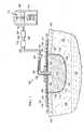
- FIG. 1is a schematic diagram with a portion shown in cross section of an illustrative, non-limiting embodiment of a dynamic, reduced-pressure treatment system
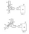
- FIG. 2is a schematic diagram with a portion shown in cross section of an illustrative, non-limiting embodiment of a wave generator for use with an embodiment of a dynamic, reduced-pressure treatment system;
- FIG. 3is a schematic diagram with a portion shown in cross section of another illustrative, non-limiting embodiment of a wave generator for use with an embodiment of a dynamic, reduced-pressure treatment system;
- FIG. 4is a schematic diagram of another illustrative embodiment of a wave generator for use with an embodiment of a dynamic, reduced-pressure treatment system
- FIG. 5is a schematic, perspective view of an illustrative embodiment of a reduced-pressure delivery member for use with an embodiment of a reduced-pressure treatment system
- FIG. 6is a schematic, perspective view of an illustrative, non-limiting embodiment of a reduced-pressure delivery member for use with an embodiment of a reduced-pressure treatment system;
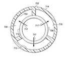
- FIG. 7is a schematic, perspective view of an illustrative, non-limiting embodiment of a reduced-pressure delivery member for use with an embodiment of a reduced-pressure treatment system.
- FIG. 8is a schematic cross section of the reduced-pressure delivery member of FIG. 7 taken along line 8 - 8 .
- a dynamic, reduced-pressure treatment system 100for treating a tissue site 104 , e.g., a wound 102 , a damaged area of tissue.
- the wound 102may involve epidermis 103 , dermis 105 , and subcutaneous tissue 107 .
- the dynamic, reduced-pressure treatment system 100may also be used at other tissue sites.
- the tissue site 104may be the bodily tissue of any human, animal, or other organism, including bone tissue, adipose tissue, muscle tissue, dermal tissue, vascular tissue, connective tissue, cartilage, tendons, ligaments, or any other tissue.
- the dynamic, reduced-pressure treatment system 100may include a manifold 112 , an sealing member 111 , a reduced-pressure delivery member 144 , a reduced-pressure subsystem 113 , and a wave generator 110 .
- the manifold 112distributes reduced pressure and may be formed from any manifold material suitable for distributing reduced pressure.
- the manifold 112is made from a porous and permeable foam material and, more particularly, a reticulated, open-cell polyurethane or polyether foam that allows good permeability of wound fluids while under a reduced pressure.
- foam materialthat has been used is the VAC GranuFoam® Dressing available from Kinetic Concepts, Inc. (KCI) of San Antonio, Tex. Any material or combination of materials may be used for the manifold material provided that the manifold material is operable to distribute the reduced pressure. Unless otherwise indicated, as used herein, “or” does not require mutual exclusivity.
- manifoldgenerally refers to a substance or structure that is provided to assist in applying reduced pressure to, delivering fluids to, or removing fluids from a tissue site.
- a manifoldtypically includes a plurality of flow channels or pathways. The plurality of flow channels may be interconnected to improve distribution of fluids provided to and removed from the area of tissue around the manifold.
- manifoldsmay include, without limitation, devices that have structural elements arranged to form flow channels, cellular foam, such as open-cell foam, porous tissue collections, and liquids, gels, and foams that include, or cure to include, flow channels.
- the manifold materialmay also be a combination or layering of materials. For example, a first manifold layer of hydrophilic foam may be disposed adjacent to a second manifold layer of hydrophobic foam to form the manifold 112 .
- the reticulated pores of the GranuFoam® materialare helpful in carrying out the manifold function, but again other materials may be used.
- a material with a higher or lower density (smaller pore size) than GranuFoam® materialmay be desirable in some situations.
- the followingmay be used: GranuFoam® material or a Foamex® technical foam (www.foamex.com).
- the manifold 112may be a bio-absorbable material or an anisotropic material.
- the sealing member 111covers the manifold 112 and extends past a peripheral edge 114 of the manifold 112 to form an extension 116 on an intact portion of the epidermis 103 .
- the extension 116has a first side 118 and a second, patient-facing side 120 .
- the extension 116may form a fluid seal against the epidermis 103 or against a gasket (e.g., another drape portion near wound edge 109 ) by a sealing apparatus 124 , and any references to forming a seal with the epidermis 103 should be regarded as also including a seal formed against such a gasket.
- the sealing apparatus 124may take numerous forms, such as an adhesive sealing tape, or drape tape or strip; a double-side drape tape; an adhesive 126 ; a paste; a hydrocolloid; a hydrogel; or other sealing device. If a tape is used, the tape may be formed of the same material as the sealing member 111 with a pre-applied, pressure-sensitive adhesive. The adhesive 126 may be applied on a second, patient-facing side 120 of the extension 116 . The adhesive 126 provides a fluid seal between the sealing member 111 and the epidermis 103 . “Fluid seal,” or “seal,” means a seal adequate to maintain reduced pressure at a desired site given the particular reduced-pressure source or subsystem involved.
- the sealing member 111may be an elastomeric material.
- “Elastomeric”means having the properties of an elastomer and generally refers to a polymeric material that has rubber-like properties. More specifically, most elastomers have elongation rates greater than 100% and a significant amount of resilience. The resilience of a material refers to the material's ability to recover from an elastic deformation.
- elastomersmay include, but are not limited to, natural rubbers, polyisoprene, styrene butadiene rubber, chloroprene rubber, polybutadiene, nitrile rubber, butyl rubber, ethylene propylene rubber, ethylene propylene diene monomer, chlorosulfonated polyethylene, polysulfide rubber, polyurethane, EVA film, co-polyester, and silicones.
- sealing member materialsmay include a silicone drape material, such as a 3M Tegaderm® drape material, an acrylic drape material, such as one available from Avery Dennison, or an incise drape material.
- the reduced-pressure subsystem 113includes a reduced-pressure source 140 , which can take many different forms, and may include the reduced-pressure interface 150 or other components to provide reduced pressure to the manifold 112 .
- the reduced-pressure source 140provides reduced pressure as a part of the dynamic, reduced-pressure treatment system 100 .
- reduced pressuregenerally refers to a pressure less than the ambient pressure at a tissue site that is being subjected to treatment. In most cases, this reduced pressure will be less than the atmospheric pressure at which the patient is located. Alternatively, the reduced pressure may be less than a hydrostatic pressure at the tissue site 104 . Unless otherwise indicated, values of pressure stated herein are gauge pressures.
- the reduced pressure deliveredmay be constant or varied (patterned or random) and may be delivered continuously or intermittently.
- vacuumand “negative pressure” may be used to describe the pressure applied to the tissue site, the actual pressure applied to the tissue site may be more than the pressure normally associated with a complete vacuum. Consistent with the use herein, an increase in reduced pressure or vacuum pressure typically refers to a relative reduction in absolute pressure.
- the reduced-pressure source 140provides reduced pressure.
- the reduced-pressure source 140may be any device for supplying a reduced pressure, such as a vacuum pump, wall suction, or other source. While the amount and nature of reduced pressure applied to a tissue site will typically vary according to the application, the reduced pressure will typically be between ⁇ 5 mm Hg and ⁇ 500 mm Hg and more typically between ⁇ 100 mm Hg and ⁇ 300 mm Hg.
- the reduced-pressure source 140is shown having a reservoir region 142 , or canister region.
- An interposed membrane filtersuch as a hydrophobic or an oleophobic filter, may be interspersed between reduced-pressure delivery member 144 and the reduced-pressure source 140 .
- a first portion 146 of reduced-pressure delivery member 144may have one or more devices, such as device 148 .
- the device 148may be another fluid reservoir, or collection member to hold exudates and other fluids removed.
- a pressure-feedback devicea volume detection system, a blood detection system, an infection detection system, a flow monitoring system, a temperature monitoring system, etc.
- Some of these devicesmay be formed integrally with the reduced-pressure source 140 .
- a reduced-pressure port 141 on reduced-pressure source 140may include a filter member that includes one or more filters, e.g., an odor filter.
- the reduced pressure developed by reduce-pressured subsystem 113is delivered through the reduced-pressure delivery member 144 to a reduced-pressure interface 150 , which may be an elbow port 152 .
- the elbow port 152is a TRAC® pad available from Kinetic Concepts, Inc. of San Antonio, Tex.
- the reduced-pressure interface 150allows the reduced pressure to be delivered through the sealing member 111 to the manifold 112 , as well as to a sealed space 154 in which the manifold 112 is located.
- the sealed space 154is formed by the sealing member 111 over the tissue site 104 .
- the reduced-pressure interface 150extends through the sealing member 111 and into the manifold 112 . Reduced pressure is supplied by the reduced-pressure delivery member 144 to the manifold 112 .
- the supply of reduced pressuremay be direct or in conjunction with reduced-pressure interface 150 .
- the wave generator 110is typically associated with the reduced-pressure delivery member 144 .
- the wave generator 110may be fluidly coupled to the reduced-pressure delivery member 144 on a second portion 138 or with a tributary conduit (see, e.g., tributary conduit 302 in FIG. 3 ).
- the wave generator 110imposes a wave form on the reduced pressure supplied by the reduced-pressure subsystem 113 ; that is, the wave generator 110 develops a wave.
- the wavetypically causes the pressure to vary at the tissue site 104 .
- the wave generator 110allows for a wide frequency range with respect to the absolute value of the pressure experienced at the tissue site 104 .
- the frequency range of the wavemay be about 0.5 Hz to about 20 Hz and greater.
- the wave generator 110may also control the amplitude of the wave.
- the wave generator 110may take many forms, such a piezoelectric transducer, a diaphragm member, a valve arrangement, etc.
- the wave generator 110creates a wave, or change in the pressure or energy in the reduced pressure in the reduced-pressure delivery member 144 .
- the changecould be accomplished with a sonic wave or a pressure wave, and so the term “wave generator” has been used.
- the wave generator 110may function to develop a sonic wave or a pressure wave by electrical means or mechanical means.
- the wave generator 110may utilize a reduced-pressure source, gear set using kinetic motion, piezoelectric transducer, a diaphragm member, a valve arrangement, etc. With respect to mechanical options, anything that produces a mechanical variation may be used, such as a displacement device.
- the wave generator 110may also be an electrically-powered membrane. Other non-limiting examples of devices and arrangements that may be used as the wave generator 110 will be presented further below in connection with FIGS. 2-4 .
- the manifold 112is placed adjacent to the tissue site 104 , and the sealing member 111 is placed over the tissue site 104 , manifold 112 , and a portion of the epidermis 103 to form a fluid seal.
- the fluid sealcreates the sealed space 154 .
- the reduced-pressure interface 150is fluidly coupled to the sealed space 154 .
- the reduced-pressure delivery member 144is fluidly coupled to the reduced-pressure source 140 and the reduced-pressure interface 150 .
- the wave generator 110is associated with the reduced-pressure delivery member 144 .
- reduced pressuremay be provided to the manifold 112 and ultimately to tissue site 104 , and when the wave generator 110 is activated, the wave generator 110 imparts a wave and provides dynamic pressure or energy variation at the wound site 104 .
- the wave generator 110may take many forms, such as a piezoelectric transducer, a diaphragm member, or an arrangement of valves, such as solenoid-operated valves.
- a piezoelectric transducersuch as a piezoelectric transducer, a diaphragm member, or an arrangement of valves, such as solenoid-operated valves.
- a wave generator 200for use as part of a dynamic, reduced-pressure treatment system is presented.
- the wave generator 200may be used as the wave generator 110 in the dynamic, reduced-pressure treatment system of FIG. 1 .
- a piezoelectric transducer 202is fluidly coupled, i.e., is placed in fluid communication with, a reduced-pressure delivery member 204 .
- the reduced-pressure delivery member 204receives reduced pressure from a reduced pressure subsystem 206 , which includes a reduced-pressure source 208 .
- the reduced-pressure subsystem 206introduces reduced pressure into the reduced-pressure delivery member 204 .
- the reduced-pressure subsystem 206also receives fluids through the reduced-pressure delivery member 204 as suggested by arrows 210 .
- the wave generator 200has been fluidly coupled to the reduced-pressure delivery member 204 .
- the wave generator 200has a movable face member 212 that extends into an interior portion of the reduced-pressure delivery member 204 or is otherwise fluidly coupled to fluid within the reduced-pressure delivery member 204 .
- the movable face member 212moves relative to the reduced-pressure delivery member 204 at a frequency that may be controlled by a power-and-control connection 214 .
- the power-and-control connection 214may be a separate power cord and a device for setting and controlling the frequency of the movable face member 212 or the amplitude of the movement of the movable face member 212 .
- the movable face member 212imparts a wave onto the fluid already present in reduced-pressure delivery member 204 .
- the wavecauses the absolute pressure or energy delivered to vary with a frequency in the range of 0.5 Hz to 20 Hz or greater.
- the wave generator 200may be a piezoelectric transducer with a piezoelectric member comprising the movable face member 212 .
- the movable face member 212is electrically driven.
- the wave generator 200may develop a wave form in the fluid of the reduced-pressure delivery member 204 with the desired frequency or wave form using physical displacement of the movable face member 212 .
- the possible frequency range, or spectrum, for the wave developed within the reduced-pressure delivery member 204 with this approachis large from 0.5 Hertz to 20 Hertz and higher.
- the frequencymay include any subset of the previously stated range, e.g., 5-20 Hz, 10-20 Hz, 5-15 Hz, etc.
- the wave generatormay take numerous other forms.
- the wave generatormay be a mechanically or electrically activated wave generator or the wave generator may utilize a diaphragm or may utilize a system of valves that turn on and off to achieve the desired effect.
- a devicecould be added to the reduced-pressure delivery conduit to press and close, i.e., pinch, the conduit or delivery member, e.g., the reduced-pressure delivery member 144 in FIG. 1 , in a pattern that causes a pressure wave.
- Another illustrative, non-limiting embodimentfollows.
- the wave generator 300includes a tributary conduit (or lumen) 302 that is fluidly coupled to a reduced-pressure delivery member 304 .
- the reduced-pressure delivery member 304is fluidly coupled to a reduced-pressure subsystem 306 .
- the reduced-pressure subsystem 306includes a reduced-pressure source 308 .
- the reduced-pressure subsystem 306delivers reduced pressure to the reduced-pressure delivery member 304 .
- the reduced-pressure subsystem 306pulls and receives fluid as suggested by arrow 310 .
- the wave generator 300includes a wave-imparting member 312 , which may be a diaphragm pump, a piston, a piezoelectric member, or any device that is operable to produce a pressure or energy wave on the fluid within the reduced-pressure delivery member 304 .
- a power-and-control connection members 314may be coupled to the wave generator 300 to provide electrical power and to control the amplitude or frequency of the energy or pressure wave imparted.
- the wave generator 400is fluidly coupled to a reduced-pressure delivery member 404 .
- the wave generator 400includes a plurality of valves, e.g., a first valve 416 , a second valve 418 , and a third valve 420 .
- the wave generator 400may further include a plurality of chambers, e.g., a first chamber 422 , second chamber 424 , and third chamber 426 .
- a plurality of regulatorse.g., a first regulator 428 , a second regulator 430 , and a third regulator 432 , is associated with the plurality of chambers.
- the first pressure regulator 428is fluidly coupled to the first chamber 422 .
- the second pressure regulator 430is fluidly coupled to the second chamber 424 .
- the third pressure regulator 432is fluidly coupled to the third chamber 426 .
- Each pressure regulator 428 , 430 , 432is operable to regulate pressure, e.g., operable to step down the pressure to a desired level.
- a manifold chamber 434is fluidly coupled to the pressure regulators 428 , 430 , 432 and provides reduced pressure thereto.
- the reduced pressureis supplied by a reduced-pressure subsystem 406 through a reduced-pressure supply conduit 405 to the manifold chamber 434 .
- the reduced-pressure subsystem 406may include a reduced-pressure source 408 .
- the pressurecan be controlled in each of the chambers 422 , 424 , and 426 to establish the desired pressure level.
- the pressure regulators 428 , 430 , and 432may reduce or increase the pressure as needed.
- the pressure regulatorse.g., regulators 428 , 430 , and 432 , increase the absolute value of the pressure in the chambers, e.g., chambers 422 , 424 , and 426 .
- the pressure in the first chamber 422may be P 1
- the pressure in the second chamber 424may be P 2
- the pressure in the third chamber 426may be P 3
- opening and closing of the valves 416 , 418 , 420may be sequenced to expose the fluid in reduced-pressure delivery member 404 to different pressures (P 1 , P 2 , and P 3 ), and thereby creates a wave.
- a controllermay be associated with the valves 416 , 418 , 420 , which may be solenoid valves, to coordinate the opening and closing of the valves 416 , 418 , 420 .
- the opening and closing of the valves 416 , 418 , and 420may allow for a wave to be generated with a frequency in the range of 0.5 Hz to 20 Hz and greater.
- the frequency rangemay be any subset of the previously stated range.
- the dynamic variation of pressure or energy by the wave generatormay help with the healing process.
- the wave generatormay help to debride or clean the wound in a continuous fashion.
- the wave generatormay generally help keep the wound cleaner by removing dead tissue.
- the wave generatormay de-sensitize nerves and thereby help reduce the patient's pain.
- the wave generatormay also help provide a dynamic motion to the tissue that causes tissue to form with a certain orientation.
- the wave generatore.g., wave generator 110 , 200 , 300 , 400
- the wave generatormay be located at various locations. Depending on how rigid aspects of the dynamic, reduced-pressure treatment system are, the wave generator may need to be close to the tissue site or may be positioned further from the tissue site. Thus, if the maximum amplitude of the wave generator is not adequate for a given location, the wave generator may need to be moved closer, and if the maximum amplitude of the wave generator is more than adequate, the wave generator could be positioned further away from the tissue site.
- the compressibility of the fluid in the reduced-pressure delivery memberwill also be a factor in determining the position of the wave generator with respect to the tissue site.
- the reduced-pressure delivery member 144may be formed in such a way as to provide a segregated portion for the liquid and another portion for any gases. By segregating the fluid from any gases, a substantially incompressible fluid or more incompressible fluid than would otherwise exist may result and be utilized with the wave generator 110 .
- the reduced-pressure delivery conduit 144may be formed in a number of ways to achieve this desired performance, and illustrative, non-limiting embodiments are described below in connection with FIGS. 5-8 .
- a reduced-pressure delivery member 500may be formed as a conduit 502 that includes at least one lumen, e.g., first lumen 504 , for transmitting a liquid (a substantially incompressible fluid), and at least one lumen, e.g., second lumen 506 , for transmitting a gas.
- the first lumen 504has a first interior space 508 .
- the second lumen 506has a second interior space 510 that is covered proximate a distal end 512 by a first liquid-impermeable-and-gas-permeable member 514 .
- the liquid-impermeable-and-gas-permeable member 514is operable to substantially restrict liquid while substantially allowing gas to enter.
- one or more additional liquid-impermeable-and-gas-permeable members 514may be located at discrete locations on the interior of the second lumen 506 or disposed continuously throughout the second interior space 510 of the second lumen 506 .
- the first liquid-impermeable-and-gas-permeable member 514may be made from any material that is liquid impermeable but gas permeable.
- the first liquid-impermeable-and-gas-permeable member 514may be formed, as one non-limiting example, from a synthetic fluoropolymer such as a poly-tetrafluoroethylene material (PTFE).
- PTFEpoly-tetrafluoroethylene material
- a third lumen 516 and a fourth lumen 518which are both analogous to first lumen 504 , are provided and are available to transmit a fluid.
- the lumens 504 , 506 , 516 , 518may be made of any fluid impermeable, flexible material, such as high-density polyethylene (HDPE), high impact polystyrene (HIPS), low-density polyethylene (LDPE), nylon, polycarbonate, polypropylene, polyethylene, polyvinyl chloride (PVC), urethanes, etc.
- HDPEhigh-density polyethylene
- HIPShigh impact polystyrene
- LDPElow-density polyethylene
- nylonpolycarbonate
- polypropylenepolyethylene
- PVCpolyvinyl chloride
- urethanesetc.
- the first liquid-impermeable-and-gas-permeable member 514substantially restricts entry into the second lumen 506 to gas while liquids may enter the first lumen 504 (and lumens 516 and 518 ).
- the liquid in the first lumen 504(or lumens 516 and 518 ) may be used with a wave generator to transmit a wave or may be used to efficiently remove fluids.
- the wave generatore.g., wave generator 110 in FIG. 1 , may be fluidly coupled to the first interior space 508 of the first lumen 504 and may also be fluidly coupled to the third lumen 516 and the fourth lumen 518 .
- the wave generated by the wave generatoris delivered through the liquid, or incompressible fluid, in the first lumen 504 or other lumens.
- the reduced-pressure delivery member 600may be formed as a conduit 602 that includes at a first lumen 604 for transmitting a liquid and a second lumen 606 for transmitting gases.
- the first lumen 604has a first interior space 608 .
- the second lumen 606has a second interior space 610 that is covered proximate a distal end 612 by a first liquid-impermeable-and-gas-permeable member 614 , which is operable to substantially restrict liquid while substantially allowing gas to enter.
- additional liquid-impermeable-and-gas-permeable membersmay be distributed at discrete locations or continuously throughout the second interior space 610 of the second lumen 606 .
- the first liquid-impermeable-and-gas-permeable member 614may be made from the same material as the first liquid-impermeable-and-gas-permeable member 514 in FIG. 5 .
- the lumens 604 and 606may be made of any fluid impermeable, flexible material.
- a wave generatore.g., wave generator 110 in FIG. 1 , may be fluidly coupled to the first lumen 604 for imparting a wave.
- the reduced-pressure delivery member 700may be formed as a conduit 702 that includes a first lumen 704 for transmitting gases (substantially compressible fluid), e.g., air, and a second lumen 706 for transmitting a liquid (substantially incompressible fluid).
- the first lumen 704has a first interior space 708 .
- a third lumen 710 and a fourth lumen 712are provided for transmitting a gas.
- the first lumen 704 , third lumen 710 , and fourth lumen 712are spaced and concentrically disposed about the second lumen 706 .
- the second lumen 706is disposed within an interior space of the other lumens 704 , 710 , 712 and defines an interior conduit therein.
- An exterior wall 714 of the conduit 702which makes up the exterior walls of the first lumen 704 , third lumen 710 , and fourth lumen 712 , is made from a fluid impermeable, flexible material, such as the materials previously mentioned.
- the exterior wall 716 of the second lumen 706is made from a liquid-impermeable-gas-permeable material, such as a synthetic fluoropolymer, e.g., a poly-tetrafluoroethylene material (PTFE).
- the exterior wall 716 of the second lumen 706is also an interior wall of the first lumen 704 , third lumen 710 , and fourth lumen 712 .
- the first lumen 704may be a 360 degree conduit with a first interior space into which the second lumen 706 is inserted.
- a wave generatormay more easily or efficiently impart a wave on the fluid when the fluid is more incompressible, and a wave generator, e.g., wave generator 110 in FIG. 1 , may be fluidly coupled to the first lumen 704 or lumens 710 and 712 for imparting a wave thereto.
- the systems and methods hereinmay allow reduced-pressure treatment of a wound site with dynamic pressure or energy that preferably allows high frequency variation and controls the pressure or energy wave amplitude. Moreover, it does so with reliability and with minimal energy requirements.
Landscapes
- Health & Medical Sciences (AREA)
- Heart & Thoracic Surgery (AREA)
- Life Sciences & Earth Sciences (AREA)
- Veterinary Medicine (AREA)
- Public Health (AREA)
- General Health & Medical Sciences (AREA)
- Animal Behavior & Ethology (AREA)
- Biomedical Technology (AREA)
- Engineering & Computer Science (AREA)
- Hematology (AREA)
- Anesthesiology (AREA)
- Vascular Medicine (AREA)
- Surgery (AREA)
- Epidemiology (AREA)
- Radiology & Medical Imaging (AREA)
- Dermatology (AREA)
- Nuclear Medicine, Radiotherapy & Molecular Imaging (AREA)
- Pain & Pain Management (AREA)
- Physical Education & Sports Medicine (AREA)
- Rehabilitation Therapy (AREA)
- Surgical Instruments (AREA)
- Media Introduction/Drainage Providing Device (AREA)
- Infusion, Injection, And Reservoir Apparatuses (AREA)
- External Artificial Organs (AREA)
- Reciprocating Pumps (AREA)
Abstract
Description
Claims (25)
Priority Applications (2)
| Application Number | Priority Date | Filing Date | Title |
|---|---|---|---|
| US12/621,340US8465465B2 (en) | 2008-11-19 | 2009-11-18 | Dynamic, reduced-pressure treatment systems and methods |
| US13/896,779US9186442B2 (en) | 2008-11-19 | 2013-05-17 | Dynamic, reduced-pressure treatment systems and methods |
Applications Claiming Priority (2)
| Application Number | Priority Date | Filing Date | Title |
|---|---|---|---|
| US11612108P | 2008-11-19 | 2008-11-19 | |
| US12/621,340US8465465B2 (en) | 2008-11-19 | 2009-11-18 | Dynamic, reduced-pressure treatment systems and methods |
Related Child Applications (1)
| Application Number | Title | Priority Date | Filing Date |
|---|---|---|---|
| US13/896,779DivisionUS9186442B2 (en) | 2008-11-19 | 2013-05-17 | Dynamic, reduced-pressure treatment systems and methods |
Publications (2)
| Publication Number | Publication Date |
|---|---|
| US20100125259A1 US20100125259A1 (en) | 2010-05-20 |
| US8465465B2true US8465465B2 (en) | 2013-06-18 |
Family
ID=42172590
Family Applications (2)
| Application Number | Title | Priority Date | Filing Date |
|---|---|---|---|
| US12/621,340Expired - Fee RelatedUS8465465B2 (en) | 2008-11-19 | 2009-11-18 | Dynamic, reduced-pressure treatment systems and methods |
| US13/896,779Active2030-07-15US9186442B2 (en) | 2008-11-19 | 2013-05-17 | Dynamic, reduced-pressure treatment systems and methods |
Family Applications After (1)
| Application Number | Title | Priority Date | Filing Date |
|---|---|---|---|
| US13/896,779Active2030-07-15US9186442B2 (en) | 2008-11-19 | 2013-05-17 | Dynamic, reduced-pressure treatment systems and methods |
Country Status (12)
| Country | Link |
|---|---|
| US (2) | US8465465B2 (en) |
| EP (2) | EP2346468B2 (en) |
| JP (2) | JP5638532B2 (en) |
| KR (1) | KR20110097852A (en) |
| CN (1) | CN102209515B (en) |
| AU (1) | AU2009316627A1 (en) |
| BR (1) | BRPI0916007A2 (en) |
| CA (1) | CA2740817C (en) |
| MX (1) | MX2011005192A (en) |
| RU (1) | RU2011113997A (en) |
| TW (1) | TW201026346A (en) |
| WO (1) | WO2010059730A2 (en) |
Cited By (1)
| Publication number | Priority date | Publication date | Assignee | Title |
|---|---|---|---|---|
| US9770369B2 (en) | 2014-08-08 | 2017-09-26 | Neogenix, Llc | Wound care devices, apparatus, and treatment methods |
Families Citing this family (87)
| Publication number | Priority date | Publication date | Assignee | Title |
|---|---|---|---|---|
| GB0224986D0 (en) | 2002-10-28 | 2002-12-04 | Smith & Nephew | Apparatus |
| US11298453B2 (en) | 2003-10-28 | 2022-04-12 | Smith & Nephew Plc | Apparatus and method for wound cleansing with actives |
| GB0508531D0 (en) | 2005-04-27 | 2005-06-01 | Smith & Nephew | Sai with ultrasound |
| GB0715259D0 (en) | 2007-08-06 | 2007-09-12 | Smith & Nephew | Canister status determination |
| US9408954B2 (en) | 2007-07-02 | 2016-08-09 | Smith & Nephew Plc | Systems and methods for controlling operation of negative pressure wound therapy apparatus |
| US12121648B2 (en) | 2007-08-06 | 2024-10-22 | Smith & Nephew Plc | Canister status determination |
| ES2715605T3 (en) | 2007-11-21 | 2019-06-05 | Smith & Nephew | Wound dressing |
| EP2214612B1 (en) | 2007-11-21 | 2019-05-01 | Smith & Nephew PLC | Wound dressing |
| GB0723872D0 (en) | 2007-12-06 | 2008-01-16 | Smith & Nephew | Apparatus for topical negative pressure therapy |
| GB2455962A (en) | 2007-12-24 | 2009-07-01 | Ethicon Inc | Reinforced adhesive backing sheet, for plaster |
| AU2009221772B2 (en) | 2008-03-05 | 2015-01-22 | Solventum Intellectual Properties Company | Dressing and method for applying reduced pressure to and collecting and storing fluid from a tissue site |
| US8298200B2 (en) | 2009-06-01 | 2012-10-30 | Tyco Healthcare Group Lp | System for providing continual drainage in negative pressure wound therapy |
| US9033942B2 (en) | 2008-03-07 | 2015-05-19 | Smith & Nephew, Inc. | Wound dressing port and associated wound dressing |
| ES2658263T3 (en) | 2008-08-08 | 2018-03-09 | Smith & Nephew, Inc. | Continuous fiber wound dressing |
| GB0900423D0 (en)* | 2009-01-12 | 2009-02-11 | Smith & Nephew | Negative pressure device |
| US8162907B2 (en) | 2009-01-20 | 2012-04-24 | Tyco Healthcare Group Lp | Method and apparatus for bridging from a dressing in negative pressure wound therapy |
| US20100324516A1 (en) | 2009-06-18 | 2010-12-23 | Tyco Healthcare Group Lp | Apparatus for Vacuum Bridging and/or Exudate Collection |
| AU2010341491B2 (en) | 2009-12-22 | 2015-05-14 | Smith & Nephew, Inc. | Apparatuses and methods for negative pressure wound therapy |
| JP6013921B2 (en) | 2010-02-23 | 2016-10-25 | エル−ヴイエイディー テクノロジー インコーポレイティッドL−Vad Technology,Inc. | Vacuum-assisted transcutaneous device |
| US8814842B2 (en) | 2010-03-16 | 2014-08-26 | Kci Licensing, Inc. | Delivery-and-fluid-storage bridges for use with reduced-pressure systems |
| USRE48117E1 (en) | 2010-05-07 | 2020-07-28 | Smith & Nephew, Inc. | Apparatuses and methods for negative pressure wound therapy |
| GB201011173D0 (en) | 2010-07-02 | 2010-08-18 | Smith & Nephew | Provision of wound filler |
| USD642594S1 (en) | 2010-10-14 | 2011-08-02 | Smith & Nephew Plc | Portable pump |
| CA140189S (en) | 2010-10-15 | 2011-11-07 | Smith & Nephew | Medical dressing |
| CA140188S (en) | 2010-10-15 | 2011-11-07 | Smith & Nephew | Medical dressing |
| GB201020005D0 (en) | 2010-11-25 | 2011-01-12 | Smith & Nephew | Composition 1-1 |
| CA2819032C (en) | 2010-11-25 | 2020-06-23 | Smith & Nephew Plc | Composition i-ii and products and uses thereof |
| RU2016111981A (en) | 2010-12-22 | 2018-11-27 | Смит Энд Нефью, Инк. | DEVICE AND METHOD FOR TREATING RAS WITH NEGATIVE PRESSURE |
| USD714433S1 (en) | 2010-12-22 | 2014-09-30 | Smith & Nephew, Inc. | Suction adapter |
| GB2488749A (en) | 2011-01-31 | 2012-09-12 | Systagenix Wound Man Ip Co Bv | Laminated silicone coated wound dressing |
| GB201106491D0 (en) | 2011-04-15 | 2011-06-01 | Systagenix Wound Man Ip Co Bv | Patterened silicone coating |
| US20150159066A1 (en) | 2011-11-25 | 2015-06-11 | Smith & Nephew Plc | Composition, apparatus, kit and method and uses thereof |
| US10940047B2 (en) | 2011-12-16 | 2021-03-09 | Kci Licensing, Inc. | Sealing systems and methods employing a hybrid switchable drape |
| CN103987348B (en) | 2011-12-16 | 2016-05-11 | 凯希特许有限公司 | Releasable Medical Drapes |
| JP6250571B2 (en) | 2012-03-12 | 2017-12-20 | スミス アンド ネフュー ピーエルシーSmith & Nephew Public Limited Company | Pressure reducing apparatus and method |
| JP6400570B2 (en) | 2012-05-23 | 2018-10-10 | スミス アンド ネフュー ピーエルシーSmith & Nephew Public Limited Company | Apparatus and method for local negative pressure closure therapy |
| CN108186200B (en) | 2012-08-01 | 2021-08-10 | 史密夫及内修公开有限公司 | Wound dressing |
| WO2014020440A1 (en) | 2012-08-01 | 2014-02-06 | Smith & Nephew Plc | Wound dressing |
| AU2013344686B2 (en) | 2012-11-16 | 2018-06-21 | Solventum Intellectual Properties Company | Medical drape with pattern adhesive layers and method of manufacturing same |
| GB201222770D0 (en) | 2012-12-18 | 2013-01-30 | Systagenix Wound Man Ip Co Bv | Wound dressing with adhesive margin |
| EP2968012B1 (en) | 2013-03-14 | 2017-04-26 | KCI Licensing, Inc. | Absorbent dressing with hybrid drape |
| EP2968647B1 (en) | 2013-03-15 | 2022-06-29 | Smith & Nephew plc | Wound dressing sealant and use thereof |
| US20160120706A1 (en) | 2013-03-15 | 2016-05-05 | Smith & Nephew Plc | Wound dressing sealant and use thereof |
| US10010658B2 (en) | 2013-05-10 | 2018-07-03 | Smith & Nephew Plc | Fluidic connector for irrigation and aspiration of wounds |
| KR101528401B1 (en)* | 2013-07-01 | 2015-06-12 | 고려대학교 산학협력단 | Wound healing apparatus negative pressure and micro current |
| EP3038667B1 (en) | 2013-08-26 | 2019-10-09 | KCI Licensing, Inc. | Dressing interface with moisture controlling feature and sealing function |
| US10946124B2 (en) | 2013-10-28 | 2021-03-16 | Kci Licensing, Inc. | Hybrid sealing tape |
| AU2014342903B2 (en) | 2013-10-30 | 2018-09-20 | Solventum Intellectual Properties Company | Dressing with differentially sized perforations |
| EP3527237B1 (en)* | 2013-10-30 | 2020-09-09 | KCI Licensing, Inc. | Absorbent conduit and system |
| EP3062751B1 (en) | 2013-10-30 | 2017-08-09 | KCI Licensing, Inc. | Condensate absorbing and dissipating system |
| US9956120B2 (en) | 2013-10-30 | 2018-05-01 | Kci Licensing, Inc. | Dressing with sealing and retention interface |
| EP3110379B1 (en) | 2014-02-28 | 2019-04-03 | KCI Licensing, Inc. | Hybrid drape having a gel-coated perforated mesh |
| US11026844B2 (en) | 2014-03-03 | 2021-06-08 | Kci Licensing, Inc. | Low profile flexible pressure transmission conduit |
| WO2015168681A1 (en) | 2014-05-02 | 2015-11-05 | Kci Licensing, Inc. | Fluid storage devices, systems, and methods |
| JP6640748B2 (en) | 2014-06-05 | 2020-02-05 | ケーシーアイ ライセンシング インコーポレイテッド | Dressing with fluid acquisition and dispensing features |
| WO2016100098A1 (en) | 2014-12-17 | 2016-06-23 | Kci Licensing, Inc. | Dressing with offloading capability |
| DK3288508T3 (en) | 2015-04-27 | 2020-03-09 | Smith & Nephew | REDUCED PRESSURE DEVICES |
| EP3574877B1 (en) | 2015-05-08 | 2022-08-17 | 3M Innovative Properties Company | Low-acuity dressing with integral pump |
| US10076594B2 (en) | 2015-05-18 | 2018-09-18 | Smith & Nephew Plc | Fluidic connector for negative pressure wound therapy |
| EP3741335B1 (en) | 2015-09-01 | 2023-05-24 | KCI Licensing, Inc. | Dressing with increased apposition force |
| EP3349807B1 (en) | 2015-09-17 | 2021-02-24 | 3M Innovative Properties Company | Hybrid silicone and acrylic adhesive cover for use with wound treatment |
| WO2017132144A1 (en)* | 2016-01-28 | 2017-08-03 | Kci Licensing, Inc. | Sequential collapse waveform dressing |
| JP1586116S (en) | 2016-02-29 | 2017-09-19 | ||
| USD796735S1 (en) | 2016-02-29 | 2017-09-05 | Smith & Nephew Plc | Mount apparatus for portable negative pressure apparatus |
| EP3426206B1 (en) | 2016-03-07 | 2023-05-10 | Smith & Nephew plc | Wound treatment apparatuses and methods with negative pressure source integrated into wound dressing |
| CA3022184A1 (en) | 2016-04-26 | 2017-11-02 | Smith & Nephew Plc | Wound dressings and methods of use with integrated negative pressure source having a fluid ingress inhibition component |
| CA3038206A1 (en) | 2016-05-03 | 2017-11-09 | Smith & Nephew Plc | Optimizing power transfer to negative pressure sources in negative pressure therapy systems |
| WO2017191158A1 (en) | 2016-05-03 | 2017-11-09 | Smith & Nephew Plc | Systems and methods for driving negative pressure sources in negative pressure therapy systems |
| US11096831B2 (en) | 2016-05-03 | 2021-08-24 | Smith & Nephew Plc | Negative pressure wound therapy device activation and control |
| WO2018037075A1 (en) | 2016-08-25 | 2018-03-01 | Smith & Nephew Plc | Absorbent negative pressure wound therapy dressing |
| EP3519001B1 (en) | 2016-09-30 | 2025-05-21 | Smith & Nephew plc | Negative pressure wound treatment apparatuses and methods with integrated electronics |
| EP3551244A1 (en) | 2016-12-12 | 2019-10-16 | Smith & Nephew PLC | Pressure wound therapy status indication via external device |
| EP3592312B1 (en) | 2017-03-08 | 2024-01-10 | Smith & Nephew plc | Negative pressure wound therapy device control in presence of fault condition |
| JP7121050B2 (en) | 2017-05-09 | 2022-08-17 | スミス アンド ネフュー ピーエルシー | Redundant control of negative pressure wound therapy systems |
| CA3074780A1 (en) | 2017-09-13 | 2019-03-21 | Smith & Nephew Plc | Negative pressure wound treatment apparatuses and methods with integrated electronics |
| GB201718070D0 (en) | 2017-11-01 | 2017-12-13 | Smith & Nephew | Negative pressure wound treatment apparatuses and methods with integrated electronics |
| GB201718072D0 (en) | 2017-11-01 | 2017-12-13 | Smith & Nephew | Negative pressure wound treatment apparatuses and methods with integrated electronics |
| GB201718014D0 (en) | 2017-11-01 | 2017-12-13 | Smith & Nephew | Dressing for negative pressure wound therapy with filter |
| GB201718054D0 (en) | 2017-11-01 | 2017-12-13 | Smith & Nephew | Sterilization of integrated negative pressure wound treatment apparatuses and sterilization methods |
| US11497653B2 (en) | 2017-11-01 | 2022-11-15 | Smith & Nephew Plc | Negative pressure wound treatment apparatuses and methods with integrated electronics |
| GB201811449D0 (en) | 2018-07-12 | 2018-08-29 | Smith & Nephew | Apparatuses and methods for negative pressure wound therapy |
| USD898925S1 (en) | 2018-09-13 | 2020-10-13 | Smith & Nephew Plc | Medical dressing |
| WO2020056014A1 (en)* | 2018-09-14 | 2020-03-19 | Kci Licensing, Inc. | Differential collapse wound dressings |
| GB201903774D0 (en) | 2019-03-20 | 2019-05-01 | Smith & Nephew | Negative pressure wound treatment apparatuses and methods with integrated electronics |
| GB201907716D0 (en) | 2019-05-31 | 2019-07-17 | Smith & Nephew | Systems and methods for extending operational time of negative pressure wound treatment apparatuses |
| GB202000574D0 (en) | 2020-01-15 | 2020-02-26 | Smith & Nephew | Fluidic connectors for negative pressure wound therapy |
| EP4585249A1 (en)* | 2024-01-12 | 2025-07-16 | BIOTRONIK SE & Co. KG | A capillary-force based approach to reducing the need for flush support on lumens in catheter systems |
Citations (123)
| Publication number | Priority date | Publication date | Assignee | Title |
|---|---|---|---|---|
| US1355846A (en) | 1920-02-06 | 1920-10-19 | David A Rannells | Medical appliance |
| US2547758A (en) | 1949-01-05 | 1951-04-03 | Wilmer B Keeling | Instrument for treating the male urethra |
| US2632443A (en) | 1949-04-18 | 1953-03-24 | Eleanor P Lesher | Surgical dressing |
| GB692578A (en) | 1949-09-13 | 1953-06-10 | Minnesota Mining & Mfg | Improvements in or relating to drape sheets for surgical use |
| US2682873A (en) | 1952-07-30 | 1954-07-06 | Johnson & Johnson | General purpose protective dressing |
| US2910763A (en) | 1955-08-17 | 1959-11-03 | Du Pont | Felt-like products |
| US2969057A (en) | 1957-11-04 | 1961-01-24 | Brady Co W H | Nematodic swab |
| US3066672A (en) | 1960-09-27 | 1962-12-04 | Jr William H Crosby | Method and apparatus for serial sampling of intestinal juice |
| US3367332A (en) | 1965-08-27 | 1968-02-06 | Gen Electric | Product and process for establishing a sterile area of skin |
| US3520300A (en) | 1967-03-15 | 1970-07-14 | Amp Inc | Surgical sponge and suction device |
| US3568675A (en) | 1968-08-30 | 1971-03-09 | Clyde B Harvey | Fistula and penetrating wound dressing |
| US3585964A (en) | 1968-06-04 | 1971-06-22 | Electrolux Ab | Apparatus operable by pressure fluid to generate pressure waves in a medium |
| US3648692A (en) | 1970-12-07 | 1972-03-14 | Parke Davis & Co | Medical-surgical dressing for burns and the like |
| US3682180A (en) | 1970-06-08 | 1972-08-08 | Coilform Co Inc | Drain clip for surgical drain |
| US3826254A (en) | 1973-02-26 | 1974-07-30 | Verco Ind | Needle or catheter retaining appliance |
| DE2640413A1 (en) | 1976-09-08 | 1978-03-09 | Wolf Gmbh Richard | CATHETER MONITORING DEVICE |
| US4080970A (en) | 1976-11-17 | 1978-03-28 | Miller Thomas J | Post-operative combination dressing and internal drain tube with external shield and tube connector |
| US4096853A (en) | 1975-06-21 | 1978-06-27 | Hoechst Aktiengesellschaft | Device for the introduction of contrast medium into an anus praeter |
| US4139004A (en) | 1977-02-17 | 1979-02-13 | Gonzalez Jr Harry | Bandage apparatus for treating burns |
| US4165748A (en) | 1977-11-07 | 1979-08-28 | Johnson Melissa C | Catheter tube holder |
| US4184510A (en) | 1977-03-15 | 1980-01-22 | Fibra-Sonics, Inc. | Valued device for controlling vacuum in surgery |
| US4233969A (en) | 1976-11-11 | 1980-11-18 | Lock Peter M | Wound dressing materials |
| US4245630A (en) | 1976-10-08 | 1981-01-20 | T. J. Smith & Nephew, Ltd. | Tearable composite strip of materials |
| US4256109A (en) | 1978-07-10 | 1981-03-17 | Nichols Robert L | Shut off valve for medical suction apparatus |
| US4261363A (en) | 1979-11-09 | 1981-04-14 | C. R. Bard, Inc. | Retention clips for body fluid drains |
| US4275721A (en) | 1978-11-28 | 1981-06-30 | Landstingens Inkopscentral Lic, Ekonomisk Forening | Vein catheter bandage |
| US4284079A (en) | 1979-06-28 | 1981-08-18 | Adair Edwin Lloyd | Method for applying a male incontinence device |
| US4297995A (en) | 1980-06-03 | 1981-11-03 | Key Pharmaceuticals, Inc. | Bandage containing attachment post |
| US4333468A (en) | 1980-08-18 | 1982-06-08 | Geist Robert W | Mesentery tube holder apparatus |
| US4373519A (en) | 1981-06-26 | 1983-02-15 | Minnesota Mining And Manufacturing Company | Composite wound dressing |
| US4382441A (en) | 1978-12-06 | 1983-05-10 | Svedman Paul | Device for treating tissues, for example skin |
| US4392858A (en) | 1981-07-16 | 1983-07-12 | Sherwood Medical Company | Wound drainage device |
| US4392853A (en) | 1981-03-16 | 1983-07-12 | Rudolph Muto | Sterile assembly for protecting and fastening an indwelling device |
| US4419097A (en) | 1981-07-31 | 1983-12-06 | Rexar Industries, Inc. | Attachment for catheter tube |
| EP0100148A1 (en) | 1982-07-06 | 1984-02-08 | Dow Corning Limited | Medical-surgical dressing and a process for the production thereof |
| US4465485A (en) | 1981-03-06 | 1984-08-14 | Becton, Dickinson And Company | Suction canister with unitary shut-off valve and filter features |
| EP0117632A2 (en) | 1983-01-27 | 1984-09-05 | Johnson & Johnson Products Inc. | Adhesive film dressing |
| US4475909A (en) | 1982-05-06 | 1984-10-09 | Eisenberg Melvin I | Male urinary device and method for applying the device |
| US4480638A (en) | 1980-03-11 | 1984-11-06 | Eduard Schmid | Cushion for holding an element of grafted skin |
| US4525166A (en) | 1981-11-21 | 1985-06-25 | Intermedicat Gmbh | Rolled flexible medical suction drainage device |
| US4525374A (en) | 1984-02-27 | 1985-06-25 | Manresa, Inc. | Treating hydrophobic filters to render them hydrophilic |
| US4540412A (en) | 1983-07-14 | 1985-09-10 | The Kendall Company | Device for moist heat therapy |
| US4543100A (en) | 1983-11-01 | 1985-09-24 | Brodsky Stuart A | Catheter and drain tube retainer |
| US4548202A (en) | 1983-06-20 | 1985-10-22 | Ethicon, Inc. | Mesh tissue fasteners |
| US4551139A (en) | 1982-02-08 | 1985-11-05 | Marion Laboratories, Inc. | Method and apparatus for burn wound treatment |
| EP0161865A2 (en) | 1984-05-03 | 1985-11-21 | Smith and Nephew Associated Companies p.l.c. | Adhesive wound dressing |
| US4569348A (en) | 1980-02-22 | 1986-02-11 | Velcro Usa Inc. | Catheter tube holder strap |
| US4605399A (en) | 1984-12-04 | 1986-08-12 | Complex, Inc. | Transdermal infusion device |
| US4608041A (en) | 1981-10-14 | 1986-08-26 | Frese Nielsen | Device for treatment of wounds in body tissue of patients by exposure to jets of gas |
| US4640688A (en) | 1985-08-23 | 1987-02-03 | Mentor Corporation | Urine collection catheter |
| US4655754A (en) | 1984-11-09 | 1987-04-07 | Stryker Corporation | Vacuum wound drainage system and lipids baffle therefor |
| US4664662A (en) | 1984-08-02 | 1987-05-12 | Smith And Nephew Associated Companies Plc | Wound dressing |
| US4710165A (en) | 1985-09-16 | 1987-12-01 | Mcneil Charles B | Wearable, variable rate suction/collection device |
| US4733659A (en) | 1986-01-17 | 1988-03-29 | Seton Company | Foam bandage |
| GB2195255A (en) | 1986-09-30 | 1988-04-07 | Vacutec Uk Limited | Method and apparatus for vacuum treatment of an epidermal surface |
| US4743232A (en) | 1986-10-06 | 1988-05-10 | The Clinipad Corporation | Package assembly for plastic film bandage |
| GB2197789A (en) | 1986-11-28 | 1988-06-02 | Smiths Industries Plc | Anti-foaming disinfectants used in surgical suction apparatus |
| US4758220A (en) | 1985-09-26 | 1988-07-19 | Alcon Laboratories, Inc. | Surgical cassette proximity sensing and latching apparatus |
| US4787888A (en) | 1987-06-01 | 1988-11-29 | University Of Connecticut | Disposable piezoelectric polymer bandage for percutaneous delivery of drugs and method for such percutaneous delivery (a) |
| US4826494A (en) | 1984-11-09 | 1989-05-02 | Stryker Corporation | Vacuum wound drainage system |
| US4838883A (en) | 1986-03-07 | 1989-06-13 | Nissho Corporation | Urine-collecting device |
| US4840187A (en) | 1986-09-11 | 1989-06-20 | Bard Limited | Sheath applicator |
| US4863449A (en) | 1987-07-06 | 1989-09-05 | Hollister Incorporated | Adhesive-lined elastic condom cathether |
| US4872450A (en) | 1984-08-17 | 1989-10-10 | Austad Eric D | Wound dressing and method of forming same |
| US4878901A (en) | 1986-10-10 | 1989-11-07 | Sachse Hans Ernst | Condom catheter, a urethral catheter for the prevention of ascending infections |
| GB2220357A (en) | 1988-05-28 | 1990-01-10 | Smiths Industries Plc | Medico-surgical containers |
| US4897081A (en) | 1984-05-25 | 1990-01-30 | Thermedics Inc. | Percutaneous access device |
| US4906233A (en) | 1986-05-29 | 1990-03-06 | Terumo Kabushiki Kaisha | Method of securing a catheter body to a human skin surface |
| US4906240A (en) | 1988-02-01 | 1990-03-06 | Matrix Medica, Inc. | Adhesive-faced porous absorbent sheet and method of making same |
| US4919654A (en) | 1988-08-03 | 1990-04-24 | Kalt Medical Corporation | IV clamp with membrane |
| CA2005436A1 (en) | 1988-12-13 | 1990-06-13 | Glenda G. Kalt | Transparent tracheostomy tube dressing |
| US4941882A (en) | 1987-03-14 | 1990-07-17 | Smith And Nephew Associated Companies, P.L.C. | Adhesive dressing for retaining a cannula on the skin |
| US4953565A (en) | 1986-11-26 | 1990-09-04 | Shunro Tachibana | Endermic application kits for external medicines |
| US4969880A (en) | 1989-04-03 | 1990-11-13 | Zamierowski David S | Wound dressing and treatment method |
| US4985019A (en) | 1988-03-11 | 1991-01-15 | Michelson Gary K | X-ray marker |
| GB2235877A (en) | 1989-09-18 | 1991-03-20 | Antonio Talluri | Closed wound suction apparatus |
| US5037397A (en) | 1985-05-03 | 1991-08-06 | Medical Distributors, Inc. | Universal clamp |
| US5086170A (en) | 1989-01-16 | 1992-02-04 | Roussel Uclaf | Process for the preparation of azabicyclo compounds |
| US5092858A (en) | 1990-03-20 | 1992-03-03 | Becton, Dickinson And Company | Liquid gelling agent distributor device |
| US5100396A (en) | 1989-04-03 | 1992-03-31 | Zamierowski David S | Fluidic connection system and method |
| US5134994A (en) | 1990-02-12 | 1992-08-04 | Say Sam L | Field aspirator in a soft pack with externally mounted container |
| US5149331A (en) | 1991-05-03 | 1992-09-22 | Ariel Ferdman | Method and device for wound closure |
| US5167613A (en) | 1992-03-23 | 1992-12-01 | The Kendall Company | Composite vented wound dressing |
| US5176663A (en) | 1987-12-02 | 1993-01-05 | Pal Svedman | Dressing having pad with compressibility limiting elements |
| US5215522A (en) | 1984-07-23 | 1993-06-01 | Ballard Medical Products | Single use medical aspirating device and method |
| US5232453A (en) | 1989-07-14 | 1993-08-03 | E. R. Squibb & Sons, Inc. | Catheter holder |
| US5261893A (en) | 1989-04-03 | 1993-11-16 | Zamierowski David S | Fastening system and method |
| US5278100A (en) | 1991-11-08 | 1994-01-11 | Micron Technology, Inc. | Chemical vapor deposition technique for depositing titanium silicide on semiconductor wafers |
| US5279550A (en) | 1991-12-19 | 1994-01-18 | Gish Biomedical, Inc. | Orthopedic autotransfusion system |
| US5298015A (en) | 1989-07-11 | 1994-03-29 | Nippon Zeon Co., Ltd. | Wound dressing having a porous structure |
| US5342376A (en) | 1993-05-03 | 1994-08-30 | Dermagraphics, Inc. | Inserting device for a barbed tissue connector |
| US5344415A (en) | 1993-06-15 | 1994-09-06 | Deroyal Industries, Inc. | Sterile system for dressing vascular access site |
| DE4306478A1 (en) | 1993-03-02 | 1994-09-08 | Wolfgang Dr Wagner | Drainage device, in particular pleural drainage device, and drainage method |
| US5358494A (en) | 1989-07-11 | 1994-10-25 | Svedman Paul | Irrigation dressing |
| US5437651A (en) | 1993-09-01 | 1995-08-01 | Research Medical, Inc. | Medical suction apparatus |
| US5437622A (en) | 1992-04-29 | 1995-08-01 | Laboratoire Hydrex (Sa) | Transparent adhesive dressing with reinforced starter cuts |
| DE29504378U1 (en) | 1995-03-15 | 1995-09-14 | MTG Medizinisch, technische Gerätebau GmbH, 66299 Friedrichsthal | Electronically controlled low-vacuum pump for chest and wound drainage |
| US5527293A (en) | 1989-04-03 | 1996-06-18 | Kinetic Concepts, Inc. | Fastening system and method |
| US5549584A (en) | 1994-02-14 | 1996-08-27 | The Kendall Company | Apparatus for removing fluid from a wound |
| US5556375A (en) | 1994-06-16 | 1996-09-17 | Hercules Incorporated | Wound dressing having a fenestrated base layer |
| US5607388A (en) | 1994-06-16 | 1997-03-04 | Hercules Incorporated | Multi-purpose wound dressing |
| US5636643A (en) | 1991-11-14 | 1997-06-10 | Wake Forest University | Wound treatment employing reduced pressure |
| US5645081A (en) | 1991-11-14 | 1997-07-08 | Wake Forest University | Method of treating tissue damage and apparatus for same |
| GB2333965A (en) | 1997-09-12 | 1999-08-11 | Kci Medical Ltd | Surgical drape |
| US6071267A (en) | 1998-02-06 | 2000-06-06 | Kinetic Concepts, Inc. | Medical patient fluid management interface system and method |
| US6135116A (en) | 1997-07-28 | 2000-10-24 | Kci Licensing, Inc. | Therapeutic method for treating ulcers |
| US6241747B1 (en) | 1993-05-03 | 2001-06-05 | Quill Medical, Inc. | Barbed Bodily tissue connector |
| US6287316B1 (en) | 1999-03-26 | 2001-09-11 | Ethicon, Inc. | Knitted surgical mesh |
| US6398767B1 (en) | 1997-05-27 | 2002-06-04 | Wilhelm Fleischmann | Process and device for application of active substances to a wound surface area |
| US20020077661A1 (en) | 2000-12-20 | 2002-06-20 | Vahid Saadat | Multi-barbed device for retaining tissue in apposition and methods of use |
| US20020115951A1 (en) | 2001-02-22 | 2002-08-22 | Core Products International, Inc. | Ankle brace providing upper and lower ankle adjustment |
| US20020120185A1 (en) | 2000-05-26 | 2002-08-29 | Kci Licensing, Inc. | System for combined transcutaneous blood gas monitoring and vacuum assisted wound closure |
| US20020143286A1 (en) | 2001-03-05 | 2002-10-03 | Kci Licensing, Inc. | Vacuum assisted wound treatment apparatus and infection identification system and method |
| US6488643B1 (en) | 1998-10-08 | 2002-12-03 | Kci Licensing, Inc. | Wound healing foot wrap |
| US6493568B1 (en) | 1994-07-19 | 2002-12-10 | Kci Licensing, Inc. | Patient interface system |
| AU755496B2 (en) | 1997-09-12 | 2002-12-12 | Kci Licensing, Inc. | Surgical drape and suction head for wound treatment |
| US6695823B1 (en) | 1999-04-09 | 2004-02-24 | Kci Licensing, Inc. | Wound therapy device |
| US6994702B1 (en) | 1999-04-06 | 2006-02-07 | Kci Licensing, Inc. | Vacuum assisted closure pad with adaptation for phototherapy |
| US7004915B2 (en) | 2001-08-24 | 2006-02-28 | Kci Licensing, Inc. | Negative pressure assisted tissue treatment system |
| US20070167927A1 (en) | 1995-11-14 | 2007-07-19 | Kci Licensing, Inc. | Portable wound treatment apparatus having pressure feedback capabilities |
| US20070239078A1 (en)* | 2006-01-23 | 2007-10-11 | Kci Licensing, Inc. | System and method for treating a wound using ultrasonic debribement |
| JP4129536B2 (en) | 2000-02-24 | 2008-08-06 | ヴェネテック インターナショナル,インコーポレイテッド | Highly compatible catheter anchoring system |
| US20080269651A1 (en)* | 2007-04-25 | 2008-10-30 | General Patent Llc | Wound care vacuum bandaging in combination with acoustic shock wave applications |
Family Cites Families (27)
| Publication number | Priority date | Publication date | Assignee | Title |
|---|---|---|---|---|
| FR14151E (en) | 1909-12-14 | 1911-09-27 | Oscar Helmer | Method and device for the sphygmorythmic control of apparatus used in physiotherapy |
| US2159164A (en) | 1934-12-24 | 1939-05-23 | Electrolux Corp | Suction nozzle |
| CH315458A (en) | 1952-09-01 | 1956-08-15 | Adam Dipl Ing Demeny | Massage machine |
| US4266545A (en) | 1979-04-06 | 1981-05-12 | Moss James P | Portable suction device for collecting fluids from a closed wound |
| EP0256060A1 (en) | 1986-01-31 | 1988-02-24 | OSMOND, Roger L. W. | Suction system for wound and gastro-intestinal drainage |
| US4748973A (en) | 1987-02-02 | 1988-06-07 | Cho Robert J | Pneumatic massage device |
| US4985055A (en) | 1988-12-19 | 1991-01-15 | The Boc Group, Inc. | Liquid/gas separation device |
| GB8906100D0 (en) | 1989-03-16 | 1989-04-26 | Smith & Nephew | Laminates |
| JPH0711764Y2 (en)* | 1992-06-10 | 1995-03-22 | 三浦工業株式会社 | Gas separation membrane module |
| DE69505545T2 (en) | 1994-08-22 | 1999-03-11 | Kinetic Concepts Inc | WOUND DRAINAGE DEVICE |
| JPH1060339A (en)* | 1996-08-23 | 1998-03-03 | Ricoh Co Ltd | Ink degassing apparatus and ink degassing method |
| DE19935521C2 (en)* | 1999-07-28 | 2001-07-19 | Kone Corp | Method for controlling the brake (s) of an escalator or moving walk |
| IL137689A0 (en)* | 2000-08-03 | 2001-10-31 | L R Res & Dev Ltd | System for enhanced chemical debridement |
| US20030032900A1 (en)* | 2001-08-08 | 2003-02-13 | Engii (2001) Ltd. | System and method for facial treatment |
| GB0508531D0 (en) | 2005-04-27 | 2005-06-01 | Smith & Nephew | Sai with ultrasound |
| GB0508528D0 (en)* | 2005-04-27 | 2005-06-01 | Smith & Nephew | SAI with macrostress |
| GB0409292D0 (en)* | 2004-04-27 | 2004-06-02 | Smith & Nephew | Apparatus with ultrasound |
| JP2009525087A (en)* | 2006-02-02 | 2009-07-09 | コロプラスト アクティーゼルスカブ | Suction method and wound suction system |
| US20090005746A1 (en)* | 2006-02-02 | 2009-01-01 | Brian Nielsen | Suction System |
| KR101164293B1 (en)* | 2006-03-14 | 2012-07-09 | 케이씨아이 라이센싱 인코포레이티드 | System and method for purging a reduced pressure apparatus during the administration of reduced pressure treatment |
| US7779625B2 (en)* | 2006-05-11 | 2010-08-24 | Kalypto Medical, Inc. | Device and method for wound therapy |
| US20080097252A1 (en)* | 2006-08-25 | 2008-04-24 | Eilaz Babaev | Ultrasound and Pressure Therapy Wound Care Device |
| US8377016B2 (en) | 2007-01-10 | 2013-02-19 | Wake Forest University Health Sciences | Apparatus and method for wound treatment employing periodic sub-atmospheric pressure |
| WO2008100446A2 (en) | 2007-02-09 | 2008-08-21 | Kci Licensing Inc. | Apparatus and method for administering reduced pressure treatment to a tissue site |
| CA2920159A1 (en) | 2007-02-09 | 2008-08-21 | Selective Broadcasting Corporation | System and method for providing telephonic access to an audio stream |
| US8057446B2 (en)* | 2007-05-01 | 2011-11-15 | The Brigham And Women's Hospital, Inc. | Wound healing device |
| US8366692B2 (en)* | 2008-01-08 | 2013-02-05 | Richard Scott Weston | Sustained variable negative pressure wound treatment and method of controlling same |
- 2009
- 2009-11-18MXMX2011005192Apatent/MX2011005192A/ennot_activeApplication Discontinuation
- 2009-11-18EPEP09828171.0Apatent/EP2346468B2/enactiveActive
- 2009-11-18CNCN2009801445546Apatent/CN102209515B/ennot_activeExpired - Fee Related
- 2009-11-18AUAU2009316627Apatent/AU2009316627A1/ennot_activeAbandoned
- 2009-11-18JPJP2011536619Apatent/JP5638532B2/ennot_activeExpired - Fee Related
- 2009-11-18BRBRPI0916007Apatent/BRPI0916007A2/ennot_activeApplication Discontinuation
- 2009-11-18RURU2011113997/14Apatent/RU2011113997A/enunknown
- 2009-11-18CACA2740817Apatent/CA2740817C/ennot_activeExpired - Fee Related
- 2009-11-18USUS12/621,340patent/US8465465B2/ennot_activeExpired - Fee Related
- 2009-11-18WOPCT/US2009/064993patent/WO2010059730A2/enactiveApplication Filing
- 2009-11-18EPEP18188688.8Apatent/EP3427712A1/ennot_activeWithdrawn
- 2009-11-18KRKR1020117014056Apatent/KR20110097852A/ennot_activeWithdrawn
- 2009-11-19TWTW098139370Apatent/TW201026346A/enunknown
- 2013
- 2013-05-17USUS13/896,779patent/US9186442B2/enactiveActive
- 2014
- 2014-07-17JPJP2014147034Apatent/JP5878210B2/ennot_activeExpired - Fee Related
Patent Citations (129)
| Publication number | Priority date | Publication date | Assignee | Title |
|---|---|---|---|---|
| US1355846A (en) | 1920-02-06 | 1920-10-19 | David A Rannells | Medical appliance |
| US2547758A (en) | 1949-01-05 | 1951-04-03 | Wilmer B Keeling | Instrument for treating the male urethra |
| US2632443A (en) | 1949-04-18 | 1953-03-24 | Eleanor P Lesher | Surgical dressing |
| GB692578A (en) | 1949-09-13 | 1953-06-10 | Minnesota Mining & Mfg | Improvements in or relating to drape sheets for surgical use |
| US2682873A (en) | 1952-07-30 | 1954-07-06 | Johnson & Johnson | General purpose protective dressing |
| US2910763A (en) | 1955-08-17 | 1959-11-03 | Du Pont | Felt-like products |
| US2969057A (en) | 1957-11-04 | 1961-01-24 | Brady Co W H | Nematodic swab |
| US3066672A (en) | 1960-09-27 | 1962-12-04 | Jr William H Crosby | Method and apparatus for serial sampling of intestinal juice |
| US3367332A (en) | 1965-08-27 | 1968-02-06 | Gen Electric | Product and process for establishing a sterile area of skin |
| US3520300A (en) | 1967-03-15 | 1970-07-14 | Amp Inc | Surgical sponge and suction device |
| US3585964A (en) | 1968-06-04 | 1971-06-22 | Electrolux Ab | Apparatus operable by pressure fluid to generate pressure waves in a medium |
| US3568675A (en) | 1968-08-30 | 1971-03-09 | Clyde B Harvey | Fistula and penetrating wound dressing |
| US3682180A (en) | 1970-06-08 | 1972-08-08 | Coilform Co Inc | Drain clip for surgical drain |
| US3648692A (en) | 1970-12-07 | 1972-03-14 | Parke Davis & Co | Medical-surgical dressing for burns and the like |
| US3826254A (en) | 1973-02-26 | 1974-07-30 | Verco Ind | Needle or catheter retaining appliance |
| US4096853A (en) | 1975-06-21 | 1978-06-27 | Hoechst Aktiengesellschaft | Device for the introduction of contrast medium into an anus praeter |
| DE2640413A1 (en) | 1976-09-08 | 1978-03-09 | Wolf Gmbh Richard | CATHETER MONITORING DEVICE |
| US4245630A (en) | 1976-10-08 | 1981-01-20 | T. J. Smith & Nephew, Ltd. | Tearable composite strip of materials |
| US4233969A (en) | 1976-11-11 | 1980-11-18 | Lock Peter M | Wound dressing materials |
| US4080970A (en) | 1976-11-17 | 1978-03-28 | Miller Thomas J | Post-operative combination dressing and internal drain tube with external shield and tube connector |
| US4139004A (en) | 1977-02-17 | 1979-02-13 | Gonzalez Jr Harry | Bandage apparatus for treating burns |
| US4184510A (en) | 1977-03-15 | 1980-01-22 | Fibra-Sonics, Inc. | Valued device for controlling vacuum in surgery |
| US4165748A (en) | 1977-11-07 | 1979-08-28 | Johnson Melissa C | Catheter tube holder |
| US4256109A (en) | 1978-07-10 | 1981-03-17 | Nichols Robert L | Shut off valve for medical suction apparatus |
| US4275721A (en) | 1978-11-28 | 1981-06-30 | Landstingens Inkopscentral Lic, Ekonomisk Forening | Vein catheter bandage |
| US4382441A (en) | 1978-12-06 | 1983-05-10 | Svedman Paul | Device for treating tissues, for example skin |
| US4284079A (en) | 1979-06-28 | 1981-08-18 | Adair Edwin Lloyd | Method for applying a male incontinence device |
| US4261363A (en) | 1979-11-09 | 1981-04-14 | C. R. Bard, Inc. | Retention clips for body fluid drains |
| US4569348A (en) | 1980-02-22 | 1986-02-11 | Velcro Usa Inc. | Catheter tube holder strap |
| US4480638A (en) | 1980-03-11 | 1984-11-06 | Eduard Schmid | Cushion for holding an element of grafted skin |
| US4297995A (en) | 1980-06-03 | 1981-11-03 | Key Pharmaceuticals, Inc. | Bandage containing attachment post |
| US4333468A (en) | 1980-08-18 | 1982-06-08 | Geist Robert W | Mesentery tube holder apparatus |
| US4465485A (en) | 1981-03-06 | 1984-08-14 | Becton, Dickinson And Company | Suction canister with unitary shut-off valve and filter features |
| US4392853A (en) | 1981-03-16 | 1983-07-12 | Rudolph Muto | Sterile assembly for protecting and fastening an indwelling device |
| US4373519A (en) | 1981-06-26 | 1983-02-15 | Minnesota Mining And Manufacturing Company | Composite wound dressing |
| US4392858A (en) | 1981-07-16 | 1983-07-12 | Sherwood Medical Company | Wound drainage device |
| US4419097A (en) | 1981-07-31 | 1983-12-06 | Rexar Industries, Inc. | Attachment for catheter tube |
| US4608041A (en) | 1981-10-14 | 1986-08-26 | Frese Nielsen | Device for treatment of wounds in body tissue of patients by exposure to jets of gas |
| US4525166A (en) | 1981-11-21 | 1985-06-25 | Intermedicat Gmbh | Rolled flexible medical suction drainage device |
| US4551139A (en) | 1982-02-08 | 1985-11-05 | Marion Laboratories, Inc. | Method and apparatus for burn wound treatment |
| US4475909A (en) | 1982-05-06 | 1984-10-09 | Eisenberg Melvin I | Male urinary device and method for applying the device |
| EP0100148A1 (en) | 1982-07-06 | 1984-02-08 | Dow Corning Limited | Medical-surgical dressing and a process for the production thereof |
| EP0117632A2 (en) | 1983-01-27 | 1984-09-05 | Johnson & Johnson Products Inc. | Adhesive film dressing |
| US4548202A (en) | 1983-06-20 | 1985-10-22 | Ethicon, Inc. | Mesh tissue fasteners |
| US4540412A (en) | 1983-07-14 | 1985-09-10 | The Kendall Company | Device for moist heat therapy |
| US4543100A (en) | 1983-11-01 | 1985-09-24 | Brodsky Stuart A | Catheter and drain tube retainer |
| US4525374A (en) | 1984-02-27 | 1985-06-25 | Manresa, Inc. | Treating hydrophobic filters to render them hydrophilic |
| EP0161865A2 (en) | 1984-05-03 | 1985-11-21 | Smith and Nephew Associated Companies p.l.c. | Adhesive wound dressing |
| US4897081A (en) | 1984-05-25 | 1990-01-30 | Thermedics Inc. | Percutaneous access device |
| US5215522A (en) | 1984-07-23 | 1993-06-01 | Ballard Medical Products | Single use medical aspirating device and method |
| US4664662A (en) | 1984-08-02 | 1987-05-12 | Smith And Nephew Associated Companies Plc | Wound dressing |
| US4872450A (en) | 1984-08-17 | 1989-10-10 | Austad Eric D | Wound dressing and method of forming same |
| US4655754A (en) | 1984-11-09 | 1987-04-07 | Stryker Corporation | Vacuum wound drainage system and lipids baffle therefor |
| US4826494A (en) | 1984-11-09 | 1989-05-02 | Stryker Corporation | Vacuum wound drainage system |
| US4605399A (en) | 1984-12-04 | 1986-08-12 | Complex, Inc. | Transdermal infusion device |
| US5037397A (en) | 1985-05-03 | 1991-08-06 | Medical Distributors, Inc. | Universal clamp |
| US4640688A (en) | 1985-08-23 | 1987-02-03 | Mentor Corporation | Urine collection catheter |
| US4710165A (en) | 1985-09-16 | 1987-12-01 | Mcneil Charles B | Wearable, variable rate suction/collection device |
| US4758220A (en) | 1985-09-26 | 1988-07-19 | Alcon Laboratories, Inc. | Surgical cassette proximity sensing and latching apparatus |
| US4733659A (en) | 1986-01-17 | 1988-03-29 | Seton Company | Foam bandage |
| US4838883A (en) | 1986-03-07 | 1989-06-13 | Nissho Corporation | Urine-collecting device |
| US4906233A (en) | 1986-05-29 | 1990-03-06 | Terumo Kabushiki Kaisha | Method of securing a catheter body to a human skin surface |
| US4840187A (en) | 1986-09-11 | 1989-06-20 | Bard Limited | Sheath applicator |
| GB2195255A (en) | 1986-09-30 | 1988-04-07 | Vacutec Uk Limited | Method and apparatus for vacuum treatment of an epidermal surface |
| US4743232A (en) | 1986-10-06 | 1988-05-10 | The Clinipad Corporation | Package assembly for plastic film bandage |
| US4878901A (en) | 1986-10-10 | 1989-11-07 | Sachse Hans Ernst | Condom catheter, a urethral catheter for the prevention of ascending infections |
| US4953565A (en) | 1986-11-26 | 1990-09-04 | Shunro Tachibana | Endermic application kits for external medicines |
| GB2197789A (en) | 1986-11-28 | 1988-06-02 | Smiths Industries Plc | Anti-foaming disinfectants used in surgical suction apparatus |
| US4941882A (en) | 1987-03-14 | 1990-07-17 | Smith And Nephew Associated Companies, P.L.C. | Adhesive dressing for retaining a cannula on the skin |
| US4787888A (en) | 1987-06-01 | 1988-11-29 | University Of Connecticut | Disposable piezoelectric polymer bandage for percutaneous delivery of drugs and method for such percutaneous delivery (a) |
| US4863449A (en) | 1987-07-06 | 1989-09-05 | Hollister Incorporated | Adhesive-lined elastic condom cathether |
| US5176663A (en) | 1987-12-02 | 1993-01-05 | Pal Svedman | Dressing having pad with compressibility limiting elements |
| US4906240A (en) | 1988-02-01 | 1990-03-06 | Matrix Medica, Inc. | Adhesive-faced porous absorbent sheet and method of making same |
| US4985019A (en) | 1988-03-11 | 1991-01-15 | Michelson Gary K | X-ray marker |
| EP0358302A2 (en) | 1988-05-28 | 1990-03-14 | Smiths Industries Public Limited Company | Medico-surgical suction container |
| GB2220357A (en) | 1988-05-28 | 1990-01-10 | Smiths Industries Plc | Medico-surgical containers |
| US4919654A (en) | 1988-08-03 | 1990-04-24 | Kalt Medical Corporation | IV clamp with membrane |
| CA2005436A1 (en) | 1988-12-13 | 1990-06-13 | Glenda G. Kalt | Transparent tracheostomy tube dressing |
| US5086170A (en) | 1989-01-16 | 1992-02-04 | Roussel Uclaf | Process for the preparation of azabicyclo compounds |
| US5527293A (en) | 1989-04-03 | 1996-06-18 | Kinetic Concepts, Inc. | Fastening system and method |
| US5100396A (en) | 1989-04-03 | 1992-03-31 | Zamierowski David S | Fluidic connection system and method |
| US5261893A (en) | 1989-04-03 | 1993-11-16 | Zamierowski David S | Fastening system and method |
| US4969880A (en) | 1989-04-03 | 1990-11-13 | Zamierowski David S | Wound dressing and treatment method |
| US5298015A (en) | 1989-07-11 | 1994-03-29 | Nippon Zeon Co., Ltd. | Wound dressing having a porous structure |
| US5358494A (en) | 1989-07-11 | 1994-10-25 | Svedman Paul | Irrigation dressing |
| US5232453A (en) | 1989-07-14 | 1993-08-03 | E. R. Squibb & Sons, Inc. | Catheter holder |
| GB2235877A (en) | 1989-09-18 | 1991-03-20 | Antonio Talluri | Closed wound suction apparatus |
| US5134994A (en) | 1990-02-12 | 1992-08-04 | Say Sam L | Field aspirator in a soft pack with externally mounted container |
| US5092858A (en) | 1990-03-20 | 1992-03-03 | Becton, Dickinson And Company | Liquid gelling agent distributor device |
| US5149331A (en) | 1991-05-03 | 1992-09-22 | Ariel Ferdman | Method and device for wound closure |
| US5278100A (en) | 1991-11-08 | 1994-01-11 | Micron Technology, Inc. | Chemical vapor deposition technique for depositing titanium silicide on semiconductor wafers |
| US5636643A (en) | 1991-11-14 | 1997-06-10 | Wake Forest University | Wound treatment employing reduced pressure |
| US5645081A (en) | 1991-11-14 | 1997-07-08 | Wake Forest University | Method of treating tissue damage and apparatus for same |
| US5279550A (en) | 1991-12-19 | 1994-01-18 | Gish Biomedical, Inc. | Orthopedic autotransfusion system |
| US5167613A (en) | 1992-03-23 | 1992-12-01 | The Kendall Company | Composite vented wound dressing |
| US5437622A (en) | 1992-04-29 | 1995-08-01 | Laboratoire Hydrex (Sa) | Transparent adhesive dressing with reinforced starter cuts |
| DE4306478A1 (en) | 1993-03-02 | 1994-09-08 | Wolfgang Dr Wagner | Drainage device, in particular pleural drainage device, and drainage method |
| US6241747B1 (en) | 1993-05-03 | 2001-06-05 | Quill Medical, Inc. | Barbed Bodily tissue connector |
| US5342376A (en) | 1993-05-03 | 1994-08-30 | Dermagraphics, Inc. | Inserting device for a barbed tissue connector |
| US5344415A (en) | 1993-06-15 | 1994-09-06 | Deroyal Industries, Inc. | Sterile system for dressing vascular access site |
| US5437651A (en) | 1993-09-01 | 1995-08-01 | Research Medical, Inc. | Medical suction apparatus |
| US5549584A (en) | 1994-02-14 | 1996-08-27 | The Kendall Company | Apparatus for removing fluid from a wound |
| US5556375A (en) | 1994-06-16 | 1996-09-17 | Hercules Incorporated | Wound dressing having a fenestrated base layer |
| US5607388A (en) | 1994-06-16 | 1997-03-04 | Hercules Incorporated | Multi-purpose wound dressing |
| US6493568B1 (en) | 1994-07-19 | 2002-12-10 | Kci Licensing, Inc. | Patient interface system |
| DE29504378U1 (en) | 1995-03-15 | 1995-09-14 | MTG Medizinisch, technische Gerätebau GmbH, 66299 Friedrichsthal | Electronically controlled low-vacuum pump for chest and wound drainage |
| US20070167927A1 (en) | 1995-11-14 | 2007-07-19 | Kci Licensing, Inc. | Portable wound treatment apparatus having pressure feedback capabilities |
| US6398767B1 (en) | 1997-05-27 | 2002-06-04 | Wilhelm Fleischmann | Process and device for application of active substances to a wound surface area |
| US6135116A (en) | 1997-07-28 | 2000-10-24 | Kci Licensing, Inc. | Therapeutic method for treating ulcers |
| US6814079B2 (en) | 1997-09-12 | 2004-11-09 | Kci Licensing, Inc. | Surgical drape and suction head for wound treatment |
| GB2329127B (en) | 1997-09-12 | 2000-08-16 | Kci Medical Ltd | Surgical drape and suction head for wound treatment |
| AU745271B2 (en) | 1997-09-12 | 2002-03-14 | Kci Licensing, Inc. | Surgical drape and suction head for wound treatment |
| GB2333965A (en) | 1997-09-12 | 1999-08-11 | Kci Medical Ltd | Surgical drape |
| US6345623B1 (en) | 1997-09-12 | 2002-02-12 | Keith Patrick Heaton | Surgical drape and suction head for wound treatment |
| US6553998B2 (en) | 1997-09-12 | 2003-04-29 | Kci Licensing, Inc. | Surgical drape and suction head for wound treatment |
| AU755496B2 (en) | 1997-09-12 | 2002-12-12 | Kci Licensing, Inc. | Surgical drape and suction head for wound treatment |
| US6071267A (en) | 1998-02-06 | 2000-06-06 | Kinetic Concepts, Inc. | Medical patient fluid management interface system and method |
| US6488643B1 (en) | 1998-10-08 | 2002-12-03 | Kci Licensing, Inc. | Wound healing foot wrap |
| US6287316B1 (en) | 1999-03-26 | 2001-09-11 | Ethicon, Inc. | Knitted surgical mesh |
| US6994702B1 (en) | 1999-04-06 | 2006-02-07 | Kci Licensing, Inc. | Vacuum assisted closure pad with adaptation for phototherapy |
| US6695823B1 (en) | 1999-04-09 | 2004-02-24 | Kci Licensing, Inc. | Wound therapy device |
| JP4129536B2 (en) | 2000-02-24 | 2008-08-06 | ヴェネテック インターナショナル,インコーポレイテッド | Highly compatible catheter anchoring system |
| US20020120185A1 (en) | 2000-05-26 | 2002-08-29 | Kci Licensing, Inc. | System for combined transcutaneous blood gas monitoring and vacuum assisted wound closure |
| US20020077661A1 (en) | 2000-12-20 | 2002-06-20 | Vahid Saadat | Multi-barbed device for retaining tissue in apposition and methods of use |
| US20020115951A1 (en) | 2001-02-22 | 2002-08-22 | Core Products International, Inc. | Ankle brace providing upper and lower ankle adjustment |
| US20020143286A1 (en) | 2001-03-05 | 2002-10-03 | Kci Licensing, Inc. | Vacuum assisted wound treatment apparatus and infection identification system and method |
| US7004915B2 (en) | 2001-08-24 | 2006-02-28 | Kci Licensing, Inc. | Negative pressure assisted tissue treatment system |
| US20070239078A1 (en)* | 2006-01-23 | 2007-10-11 | Kci Licensing, Inc. | System and method for treating a wound using ultrasonic debribement |
| US20080269651A1 (en)* | 2007-04-25 | 2008-10-30 | General Patent Llc | Wound care vacuum bandaging in combination with acoustic shock wave applications |
Non-Patent Citations (42)
| Title |
|---|
| A.A. Safronov, Dissertation Abstract, Vacuum Therapy of Trophic Ulcers of the Lower Leg with Simultaneous Autoplasty of the Skin (Central Scientific Research Institute of Traumatology and Orthopedics, Moscow, U.S.S.R. 1967). |
| Arnljots, Björn et al.: "Irrigation Treatment in Split-Thickness Skin Grafting of Intractable Leg Ulcers", Scand J. Plast Reconstr. Surg., No. 19, 1985, pp. 211-213. |
| C.E. Tennants, "The Use of Hypermia in the Postoperative Treatment of Lesions of the Extremities and Thorax," Journal of the American Medical Association 64 (1915), pp. 1548-1549. |
| Chariker, Mark E., M.D., et al; "Effective Management of incisional and cutaneous fistulae with closed suction wound drainage"; Contemporary Surgery, vol. 34, Jun. 1989, pp. 59-63. |
| Chinn, Steven D. et al.: "Closed Wound Suction Drainage", The Journal of Foot Surgery, vol. 24, No. 1, 1985, pp. 76-81. |
| D.E. Tribble, An Improved Sump Drain-Irrigation Device of Simple Construction, Archives of Surgery 105 (1972) pp. 511-513. |
| Dattilo, Philip P., Jr., et al; "Medical Textiles: Application of an Absorbable Barbed Bi-directional Surgical Suture"; Journal of Textile and Apparel, Technology and Management, vol. 2, Issue 2, Spring 2002, pp. 1-5. |
| Davydov, Yu. A., et al; "Bacteriological and Cytological Assessment of Vacuum Therapy for Purulent Wounds"; Vestnik Khirurgi, Oct 1988, pp. 48-52, and 8 page English translation thereof. |
| Davydov, Yu. A., et al; "Concepts for the Clinical-Biological Management of the Wound Process in the Treatment of Purulent Wounds by Means of Vacuum Therapy"; Vestnik Khirurgi, Jul. 7, 1980, pp. 132-136, and 8 page English translation thereof. |
| Davydov, Yu. A., et al; "Vacuum Therapy in the Treatment of Purulent Lactation Mastitis"; Vestnik Khirurgi, May 14, 1986, pp. 66-70, and 9 page English translation thereof. |
| Egnell Minor, Instruction Book, First Edition, 300 7502, Feb. 1975, pp. 24. |
| Egnell Minor: Addition to the Users Manual Concerning Overflow Protection-Concerns all Egnell Pumps, Feb. 3, 1983, pp. 2. |
| F.E. Johnson, "An Improved Technique for Skin Graft Placement Using a Suction Drain," Surgery, Gynecology, and Obstetrics 159 (1984), pp. 584-585. |
| G. {hacek over (Z)}ivadinovic, V. ukic, {hacek over (Z)}. Maksimovic, . Radak, and P. Pe{hacek over (s)}ka, "Vacuum Therapy in the Treatment of Peripheral Blood Vessels," Timok Medical Journal 11 (1986), pp. 161-164. |
| G. {hacek over (Z)}ivadinović, V. ukić, {hacek over (Z)}. Maksimović, . Radak, and P. Pe{hacek over (s)}ka, "Vacuum Therapy in the Treatment of Peripheral Blood Vessels," Timok Medical Journal 11 (1986), pp. 161-164. |
| George V. Letsou, MD., et al; "Stimulation of Adenylate Cyclase Activity in Cultured Endothelial Cells Subjected to Cyclic Stretch"; Journal of Cardiovascular Surgery, 31, 1990, pp. 634-639. |
| International Search Report and Written Opinion date mailed Jul. 5, 2010 for PCT International Application No. PCT/US2009/064993. |
| International Search Report for PCT International Application PCT/GB95/01983; Nov. 23, 1995. |
| James H. Blackburn, II, MD, et al; "Negative-Pressure Dressings as a Bolster for Skin Grafts"; Annals of Plastic Surgery, vol. 40, No. 5, May 1998, pp. 453-457. |
| John Masters; "Reliable, Inexpensive and Simple Suction Dressings"; Letter to the Editor, British Journal of Plastic Surgery, 1998, vol. 51 (3), p. 267; Elsevier Science/The British Association of Plastic Surgeons, UK. |
| K.F. Jeter, T.E. Tintle, and M. Chariker, Managing Draining Wounds and Fistulae: "New and Established Methods," Chronic Wound Care, edited by D. Krasner (Health Management Publications, Inc., King of Prussia, PA 1990), pp. 240-246. |
| Kostyuchenok, B.M., et al; "Vacuum Treatment in the Surgical Management of Purulent Wounds"; Vestnik Khirurgi, Sep. 1986, pp. 18-21 and 6 page English translation thereof. |
| Louis C. Argenta, MD and Michael J. Morykwas, PhD; "Vacuum-Assisted Closure: A New Method for Wound Control and Treatment: Clinical Experience"; Annals of Plastic Surgery, vol. 38, No. 6, Jun. 1997; pp. 563-576. |
| M. Schein, R. Saadia, J.R. Jamieson, and G.A.G. Decker, "The 'Sandwich Technique' in the Management of the Open Abdomen," British Journal of Surgery 73 (1986), pp. 369-370. |
| M.J. Morykwas, L.C. Argenta, E.I. Shelton-Brown, and W. McGuirt, "Vacuum-Assisted Closure: A New Method for Wound Control and Treatment: Animal Studies and Basic Foundation," Annals of Plastic Surgery 38 (1997), pp. 553-562 (Morykwas I). |
| N. A. Bagautdinov, "Variant of External Vacuum Aspiration in the Treatment of Purulent Diseases of the Soft Tissues," Current Problems in Modem Clinical Surgery: Interdepartmental Collection, edited by V. Ye Volkov et al. (Chuvashia State University, Cheboksary, U.S.S.R. 1986);pp. 94-96 (certified translation). |
| Orringer, Jay, et al; "Management of Wounds in Patients with Complex Enterocutaneous Fistulas"; Surgery, Gynecology & Obstetrics, Jul. 1987, vol. 165, pp. 79-80. |
| PCT International Examination and Search Report, PCT International Application PCT/GB96/02802; Jan. 15, 1998 & Apr. 29, 1997. |
| PCT International Search Report for PCT International Application PCT/GB98/02713; Jan. 8, 1999. |
| PCT Written Opinion, PCT International Application PCT/GB96/02802; Sep. 3, 1997. |
| PCT Written Opinion; PCT International Application PCT/GB98/02713; Jun. 8, 1999. |
| S.E. Greer, et al "The Use of Subatmospheric Pressure Dressing Therapy to Close Lymphocutaneous Fistulas of the Groin" British Journal of Plastic Surgery (2000), 53, pp. 484-487. |
| Selections from W. Meyer and V. Schmieden, Bier's Hyperemic Treatment in Surgery, Medicine, and the Specialties: A Manual of Its Practical Application, (W.B. Saunders Co., Philadelphia, PA 1909), pp. 17-25, 44-64, 90-96, 167-170, and 210-211. |
| Susan Mendez-Eastmen, RN; "When Wounds Won't Heal" RN Jan. 1998, vol. 61 (1); Medical Economics Company, Inc., Montvale, NJ, USA; pp. 20-24. |
| Svedman, P. et al.: "A Dressing System Providing Fluid Supply and Suction Drainage Used for Continuous or Intermittent Irrigation", Annals of Plastic Surgery, vol. 17, No. 2, Aug. 1986, pp. 125-133. |
| Svedman, P.: "A Dressing Allowing Continuous Treatment of a Biosurface", IRCS Medical Science: Biomedical Technology, Clinical Medicine, Surgery and Transplantation, vol. 7, 1979, p. 221. |
| Svedman, P.: "Irrigation Treatment of Leg Ulcers", The Lancet, Sep. 3, 1983, pp. 532-534. |
| V.A. Kuznetsov & N. A. Bagautdinov, "Vacuum and Vacuum-Sorption Treatment of Open Septic Wounds," in II All-Union Conference on Wounds and Wound Infections: Presentation Abstracts, edited by B.M. Kostyuchenok et al. (Moscow, U.S.S.R. Oct. 28-29, 1986) pp. 91-92 ("Bagautdinov II"). |
| V.A. Solovev et al., Guidelines, The Method of Treatment of Immature External Fistulas in the Upper Gastrointestinal Tract, editor-in-chief Prov. V.I. Parahonyak (S.M. Kirov Gorky State Medical Institute, Gorky, U.S.S.R. 1987) ("Solovev Guidelines"). |
| V.A. Solovev, Dissertation Abstract, Treatment and Prevention of Suture Failures after Gastric Resection (S.M. Kirov Gorky State Medical Institute, Gorky, U.S.S.R. 1988) ("Solovev Abstract"). |
| V.A.C.® Therapy Clinical Guidelines: A Reference Source for Clinicians (Jul. 2007). |
| Yusupov. Yu. N., et al; "Active Wound Drainage", Vestnik Khirurgi, vol. 138, Issue 4, 1987, and 7 page English translation thereof. |
Cited By (1)
| Publication number | Priority date | Publication date | Assignee | Title |
|---|---|---|---|---|
| US9770369B2 (en) | 2014-08-08 | 2017-09-26 | Neogenix, Llc | Wound care devices, apparatus, and treatment methods |
Also Published As
| Publication number | Publication date |
|---|---|
| CA2740817A1 (en) | 2010-05-27 |
| AU2009316627A1 (en) | 2010-05-27 |
| JP5878210B2 (en) | 2016-03-08 |
| RU2011113997A (en) | 2012-12-27 |
| MX2011005192A (en) | 2011-06-01 |
| BRPI0916007A2 (en) | 2015-11-03 |
| CA2740817C (en) | 2017-04-18 |
| WO2010059730A3 (en) | 2010-08-26 |
| JP2012509112A (en) | 2012-04-19 |
| CN102209515A (en) | 2011-10-05 |
| EP2346468B2 (en) | 2025-03-26 |
| JP2014237000A (en) | 2014-12-18 |
| US20130253453A1 (en) | 2013-09-26 |
| EP2346468B1 (en) | 2018-09-26 |
| WO2010059730A2 (en) | 2010-05-27 |
| TW201026346A (en) | 2010-07-16 |
| EP3427712A1 (en) | 2019-01-16 |
| KR20110097852A (en) | 2011-08-31 |
| US9186442B2 (en) | 2015-11-17 |
| US20100125259A1 (en) | 2010-05-20 |
| EP2346468A2 (en) | 2011-07-27 |
| JP5638532B2 (en) | 2014-12-10 |
| CN102209515B (en) | 2013-12-11 |
| EP2346468A4 (en) | 2016-12-14 |
Similar Documents
| Publication | Publication Date | Title |
|---|---|---|
| US9186442B2 (en) | Dynamic, reduced-pressure treatment systems and methods | |
| US9345821B2 (en) | Reduced-pressure sources, systems, and methods employing a polymeric, porous, hydrophobic material | |
| US9050210B2 (en) | Laminar dressings, systems, and methods for applying reduced pressure at a tissue site | |
| EP2659915B2 (en) | Anisotropic drapes and systems | |
| US9352075B2 (en) | Wound healing apparatus for promoting granulation and epithelialization at a tissue site | |
| US20170296714A1 (en) | Reduced-Pressure Sources, Systems, And Methods Employing A Polymeric, Porous, Hydrophobic Material | |
| AU2015227407B2 (en) | Dynamic, reduced-pressure treatment systems and methods | |
| HK1160375A (en) | Dynamic, reduced-pressure treatment systems and methods |
Legal Events
| Date | Code | Title | Description |
|---|---|---|---|
| FEPP | Fee payment procedure | Free format text:PAYOR NUMBER ASSIGNED (ORIGINAL EVENT CODE: ASPN); ENTITY STATUS OF PATENT OWNER: LARGE ENTITY | |
| STCF | Information on status: patent grant | Free format text:PATENTED CASE | |
| FEPP | Fee payment procedure | Free format text:PAYOR NUMBER ASSIGNED (ORIGINAL EVENT CODE: ASPN); ENTITY STATUS OF PATENT OWNER: LARGE ENTITY Free format text:PAYER NUMBER DE-ASSIGNED (ORIGINAL EVENT CODE: RMPN); ENTITY STATUS OF PATENT OWNER: LARGE ENTITY | |
| AS | Assignment | Owner name:WILMINGTON TRUST, NATIONAL ASSOCIATION, AS COLLATERAL AGENT, MINNESOTA Free format text:SECOND LIEN SECURITY AGREEMENT;ASSIGNORS:KCI USA, INC.;LIFECELL CORPORATION;KCI LICENSING, INC.;REEL/FRAME:040098/0268 Effective date:20160920 Owner name:WILMINGTON TRUST, NATIONAL ASSOCIATION, AS COLLATE Free format text:SECOND LIEN SECURITY AGREEMENT;ASSIGNORS:KCI USA, INC.;LIFECELL CORPORATION;KCI LICENSING, INC.;REEL/FRAME:040098/0268 Effective date:20160920 | |
| AS | Assignment | Owner name:WILMINGTON TRUST, NATIONAL ASSOCIATION, AS COLLATERAL AGENT, MINNESOTA Free format text:LIMITED THIRD LIEN INTELLECTUAL PROPERTY SECURITY AGREEMENT;ASSIGNORS:KCI USA, INC.;LIFECELL CORPORATION;KCI LICENSING, INC.;REEL/FRAME:040291/0237 Effective date:20161006 Owner name:WILMINGTON TRUST, NATIONAL ASSOCIATION, AS COLLATE Free format text:LIMITED THIRD LIEN INTELLECTUAL PROPERTY SECURITY AGREEMENT;ASSIGNORS:KCI USA, INC.;LIFECELL CORPORATION;KCI LICENSING, INC.;REEL/FRAME:040291/0237 Effective date:20161006 | |
| FPAY | Fee payment | Year of fee payment:4 | |
| AS | Assignment | Owner name:KCI USA, INC., TEXAS Free format text:RELEASE OF SECURITY INTEREST REEL/FRAME 040098/0268;ASSIGNOR:WILMINGTON TRUST;REEL/FRAME:041666/0320 Effective date:20170203 | |
| AS | Assignment | Owner name:KCI LICENSING, INC., TEXAS Free format text:RELEASE OF SECURITY INTEREST IN PATENTS;ASSIGNOR:WILMINGTON TRUST, NATIONAL ASSOCIATION;REEL/FRAME:050966/0547 Effective date:20191011 Owner name:KCI USA, INC., TEXAS Free format text:RELEASE OF SECURITY INTEREST IN PATENTS;ASSIGNOR:WILMINGTON TRUST, NATIONAL ASSOCIATION;REEL/FRAME:050966/0547 Effective date:20191011 | |
| FEPP | Fee payment procedure | Free format text:MAINTENANCE FEE REMINDER MAILED (ORIGINAL EVENT CODE: REM.); ENTITY STATUS OF PATENT OWNER: LARGE ENTITY | |
| LAPS | Lapse for failure to pay maintenance fees | Free format text:PATENT EXPIRED FOR FAILURE TO PAY MAINTENANCE FEES (ORIGINAL EVENT CODE: EXP.); ENTITY STATUS OF PATENT OWNER: LARGE ENTITY | |
| STCH | Information on status: patent discontinuation | Free format text:PATENT EXPIRED DUE TO NONPAYMENT OF MAINTENANCE FEES UNDER 37 CFR 1.362 | |
| FP | Lapsed due to failure to pay maintenance fee | Effective date:20210618 |