US8465151B2 - Eyewear with multi-part temple for supporting one or more electrical components - Google Patents
Eyewear with multi-part temple for supporting one or more electrical componentsDownload PDFInfo
- Publication number
- US8465151B2 US8465151B2US12/806,312US80631210AUS8465151B2US 8465151 B2US8465151 B2US 8465151B2US 80631210 AUS80631210 AUS 80631210AUS 8465151 B2US8465151 B2US 8465151B2
- Authority
- US
- United States
- Prior art keywords
- temple
- connector
- rearward
- recited
- electrical components
- Prior art date
- Legal status (The legal status is an assumption and is not a legal conclusion. Google has not performed a legal analysis and makes no representation as to the accuracy of the status listed.)
- Expired - Fee Related, expires
Links
Images


Classifications
- G—PHYSICS
- G02—OPTICS
- G02C—SPECTACLES; SUNGLASSES OR GOGGLES INSOFAR AS THEY HAVE THE SAME FEATURES AS SPECTACLES; CONTACT LENSES
- G02C11/00—Non-optical adjuncts; Attachment thereof
- G02C11/10—Electronic devices other than hearing aids
- F—MECHANICAL ENGINEERING; LIGHTING; HEATING; WEAPONS; BLASTING
- F21—LIGHTING
- F21V—FUNCTIONAL FEATURES OR DETAILS OF LIGHTING DEVICES OR SYSTEMS THEREOF; STRUCTURAL COMBINATIONS OF LIGHTING DEVICES WITH OTHER ARTICLES, NOT OTHERWISE PROVIDED FOR
- F21V33/00—Structural combinations of lighting devices with other articles, not otherwise provided for
- F21V33/0004—Personal or domestic articles
- G—PHYSICS
- G02—OPTICS
- G02C—SPECTACLES; SUNGLASSES OR GOGGLES INSOFAR AS THEY HAVE THE SAME FEATURES AS SPECTACLES; CONTACT LENSES
- G02C11/00—Non-optical adjuncts; Attachment thereof
- G02C11/06—Hearing aids
- G—PHYSICS
- G02—OPTICS
- G02C—SPECTACLES; SUNGLASSES OR GOGGLES INSOFAR AS THEY HAVE THE SAME FEATURES AS SPECTACLES; CONTACT LENSES
- G02C5/00—Constructions of non-optical parts
- G02C5/14—Side-members
- G02C5/143—Side-members having special ear pieces
- G—PHYSICS
- G02—OPTICS
- G02C—SPECTACLES; SUNGLASSES OR GOGGLES INSOFAR AS THEY HAVE THE SAME FEATURES AS SPECTACLES; CONTACT LENSES
- G02C5/00—Constructions of non-optical parts
- G02C5/14—Side-members
- G02C5/146—Side-members having special front end
- H—ELECTRICITY
- H02—GENERATION; CONVERSION OR DISTRIBUTION OF ELECTRIC POWER
- H02J—CIRCUIT ARRANGEMENTS OR SYSTEMS FOR SUPPLYING OR DISTRIBUTING ELECTRIC POWER; SYSTEMS FOR STORING ELECTRIC ENERGY
- H02J7/00—Circuit arrangements for charging or depolarising batteries or for supplying loads from batteries
- H02J7/0042—Circuit arrangements for charging or depolarising batteries or for supplying loads from batteries characterised by the mechanical construction
- H02J7/0045—Circuit arrangements for charging or depolarising batteries or for supplying loads from batteries characterised by the mechanical construction concerning the insertion or the connection of the batteries
- F—MECHANICAL ENGINEERING; LIGHTING; HEATING; WEAPONS; BLASTING
- F21—LIGHTING
- F21W—INDEXING SCHEME ASSOCIATED WITH SUBCLASSES F21K, F21L, F21S and F21V, RELATING TO USES OR APPLICATIONS OF LIGHTING DEVICES OR SYSTEMS
- F21W2111/00—Use or application of lighting devices or systems for signalling, marking or indicating, not provided for in codes F21W2102/00 – F21W2107/00
- F21W2111/10—Use or application of lighting devices or systems for signalling, marking or indicating, not provided for in codes F21W2102/00 – F21W2107/00 for personal use, e.g. hand-held
- F—MECHANICAL ENGINEERING; LIGHTING; HEATING; WEAPONS; BLASTING
- F21—LIGHTING
- F21Y—INDEXING SCHEME ASSOCIATED WITH SUBCLASSES F21K, F21L, F21S and F21V, RELATING TO THE FORM OR THE KIND OF THE LIGHT SOURCES OR OF THE COLOUR OF THE LIGHT EMITTED
- F21Y2115/00—Light-generating elements of semiconductor light sources
- F21Y2115/10—Light-emitting diodes [LED]
- G—PHYSICS
- G02—OPTICS
- G02C—SPECTACLES; SUNGLASSES OR GOGGLES INSOFAR AS THEY HAVE THE SAME FEATURES AS SPECTACLES; CONTACT LENSES
- G02C2200/00—Generic mechanical aspects applicable to one or more of the groups G02C1/00 - G02C5/00 and G02C9/00 - G02C13/00 and their subgroups
- G02C2200/08—Modular frames, easily exchangeable frame parts and lenses
Definitions
- eyeglasseshave not contained or made any use of electrical components.
- attempts to include electrical components within eyeglasseshave had limited success.
- Even incorporating a small electrical component, such as a microphone, into an eyeglass framemay not be a simple task because, for example, of the necessary electrical connections with the electrical component.
- larger scale electrical componentswould be more difficult to be provided in or attached to eyeglass frames.
- Many eyeglasses framestend to be very compact and lightweight and thus may not have a lot of space for electrical components.
- eyeglass framesare often fashionable items whose designs are important, there are substantial design tradeoffs involved with providing or attaching electrical components to eyeglass frames.
- the inventionpertains to techniques for providing eyewear with electrical components.
- the electrical componentscan provide electrical technology to eyewear (e.g., eyeglasses) without having to substantially compromise aesthetic design principles of the eyewear.
- the electrical componentscan be attached to the eyewear as an after-market enhancement.
- the electrical componentscan operate independently or together with other electrical components provided elsewhere. Apparatus can also be provided to present after-market electrical components.
- a temple arrangementfor use with eyeglasses.
- a temple arrangementincludes one or more electrical components.
- the one or more electrical componentsare attached to or at least partially embedded in the temple arrangement.
- a temple adapterfor use with eyeglasses.
- a temple adapterincludes one or more electrical components that are able to be mechanically (and optionally electrically) coupled to a temple (including a temple tip) of the eyeglasses.
- Still another aspect of the inventionrelates to one or more swappable temple portions for a pair of glasses.
- a templehas a forward portion and a rearward portion which can removably couple to one another.
- different rearward portionscan be used with the same forward portion.
- the different rearward portionscan be swapped with one another.
- the different rearward portionscan offer different electrical components/functionalities to the pair of glasses.
- the different rearward portionscan provide different electrical components/functionalities such as: battery/power, wireless communication, radio, headset, GPS, pedometer, sun sensor, hearing enhancement, image/video capturing, etc.
- different forward portionscan be used with the same rearward portion.
- Yet still another aspect of the inventionrelates to eyewear having an extended endpiece so as to facilitate placement of one or more electrical components at the extended endpiece.
- the one or more electrical componentscan operate independently or together with other electrical components provided elsewhere.
- other electrical componentscan be provided in other regions of the frame for the eyewear.
- the other electrical componentscan be located in a bridge area of the frame for the eyewear.
- the one or more electrical componentscan be placed at the endpiece and thereby communicate with other electrical components in a front area or the other endpiece without having to communicate through a hinge or connector.
- the electrical componentscan support signal capturing, signal processing, signal transmission, signal display, signal storage and/or power provision.
- the signalscan be, for example, analog or digital signals.
- the electrical componentscan, for example, be used to provide audio output and/or audio pick-up.
- the electrical componentsmay include and/or control one or more sensors to monitor and/or signal the conditions of a user of the eyewear.
- the electrical componentsmay also include and/or control one or more operation indicators to signal operational status of at least some other electrical components.
- the electrical componentscan be or pertain to a circuit board or module, which includes a plurality of electrical components.
- the inventioncan be implemented in numerous ways, including a method, system, device, apparatus, and a computer readable medium. Several embodiments of the invention are discussed below.
- FIG. 1is a perspective view of a pair of glasses according to one embodiment of the invention.
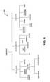
- FIG. 2illustrates a diagram of a number of different embodiments of temple arrangements according to the invention.
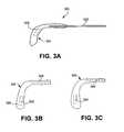
- FIG. 3Ais a diagram of a temple arrangement according to one embodiment of the invention.
- FIG. 3Bis a diagram of a temple cover that at least partially covers a temple (e.g., temple and/or temple tip) according to one embodiment of the invention.
- FIG. 3Cis a diagram of a fit-over temple that at least partially fits over a temple (e.g., temple and/or temple tip) according to one embodiment of the invention.
- a templee.g., temple and/or temple tip
- FIGS. 3D and 3Eare diagrams of a temple arrangement according to another embodiment of the invention.
- FIGS. 3F-3Hare diagrams of exemplary multi-part temples according to different embodiments of the invention.
- FIGS. 3I-3Kare diagrams of exemplary rearward portions of multi-part temples according to several embodiments of the invention.
- FIGS. 3L-3Oare diagrams of exemplary forward portions of multi-part temples according to several embodiments of the invention.
- FIG. 3Pis a diagram of an eyewear products display apparatus according to one embodiment of the invention.
- FIG. 4shows examples of different electrical components according to the invention.
- FIG. 5is a chart that depicts examples of sensors suitable for use according to the invention.
- FIG. 6illustrates a diagram of a number of different embodiments of temple adapters according to the invention.
- FIG. 7Ais a diagram of a temple adapter according to one embodiment of the invention.
- FIG. 7Bis a diagram of a temple adapter according to another embodiment of the invention.
- FIGS. 8A and 8Bare diagrams of a temple adapter according to another embodiment of the invention.
- FIG. 9Ais a diagram of a temple adapter according to one embodiment of the invention.
- FIGS. 9B and 9Care diagrams of a temple adapter according to another embodiment of the invention.
- FIG. 9Dis a diagram of a temple adapter according to still another embodiment of the invention.
- FIGS. 10A-10Care diagrams of a temple having a bone conducting element according to still other embodiments of the invention.
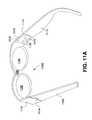
- FIG. 11Aillustrates a pair of glasses according to one embodiment of the invention.
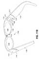
- FIG. 11Billustrates a pair of glasses according to another embodiment of the invention.
- FIGS. 12A-12Eillustrate a side view of eyeglass frames having an extended temples according to several embodiment of the invention.
- FIG. 13Aillustrates a temple having multiple parts according to one embodiment of the invention.
- FIG. 13Billustrates a portion of an eyeglass frame according to one embodiment of the invention.
- FIG. 13Cillustrates a portion of an eyeglass frame according to another embodiment of the invention.
- the inventionpertains to techniques for providing eyewear with electrical components.
- the electrical componentscan provide electrical technology to eyewear (e.g., eyeglasses) without having to substantially compromise aesthetic design principles of the eyewear.
- the electrical componentscan be attached to the eyewear as an after-market enhancement.
- the electrical componentscan operate independently or together with other electrical components provided elsewhere. Apparatus can also be provided to present after-market electrical components.
- a temple arrangementfor use with eyeglasses.
- a temple arrangementincludes one or more electrical components.
- the one or more electrical componentsare attached to or at least partially embedded in the temple arrangement.
- a temple adapterfor use with eyeglasses.
- a temple adapterincludes one or more electrical components that are able to be mechanically (and optionally electrically) coupled to a temple (including a temple tip) of the eyeglasses.
- a templehas a forward portion and a rearward portion which can removably couple to one another.
- different rearward portionscan be used with the same forward portion.
- the different rearward portionscan be swapped with one another.
- the different rearward portionscan offer different electrical components/functionalities to the pair of glasses.
- the different rearward portionscan provide different electrical components/functionalities such as: battery/power, wireless communication, radio, headset, GPS, pedometer, sun sensor, hearing enhancement, image/video capturing, etc.
- different forward portionscan be used with the same rearward portion.
- the electrical componentscan support signal capturing, signal processing, signal transmission, signal display, signal storage and/or power provision.
- the signalscan be, for example, analog or digital signals.
- the electrical componentscan, for example, be used to provide audio output and/or audio pick-up.
- the electrical componentsmay include and/or control one or more sensors to monitor and/or signal the conditions of a user of the eyewear.
- the electrical componentsmay also include and/or control one or more operation indicators to signal operational status of at least some other electrical components.
- the electrical componentscan be or pertain to a circuit board or module, which includes a plurality of electrical components.
- FIGS. 1-13CEmbodiments of different aspects of the invention are discussed below with reference to FIGS. 1-13C . However, those skilled in the art will readily appreciate that the detailed description given herein with respect to these figures is for explanatory purposes as the invention extends beyond these limited embodiments.
- FIG. 1is a perspective view of a pair of glasses 100 according to one embodiment of the invention.
- the glasses 100include a frame and a pair of lenses 102 .
- the framehas lens holders 104 that hold the lenses 102 in position.
- the framealso has a bridge 106 .
- the glasses 100further include a pair of temples (or arms) 108 .
- the temples 108are considered part of the frame.
- each of the temples 108is coupled to one of the lens holders 104 by a hinge 109 .
- the temples 108can be removed from the frame (e.g., at the hinge 109 ).
- temple arrangements 110are attached to the temples 108 .
- one or both of the temples 108can include a temple arrangement 110 .
- a temple arrangement 110can include one or more electrical components 112 .
- the temple arrangements 110can be considered separate parts that can be attached to respective temples 108 . Once attached, the temple arrangements 110 can be considered part of, or an extension to, the temples 108 .
- electrical capabilitiescan be provided to the glasses 100 without burdensome impact to the design of other parts of the frames.
- electrical capabilitiescan be added to eyeglasses in an after-market manner. Still further, by replacing temple arrangements, a user could alter the electrical capabilities of his eyeglasses.
- the glasses 100do not have any other embedded electrical components, such as within the frame, except those in one or both of the temple arrangements 112 .
- the glasses 100include one or more other electrical components embedded or attached to the frame of the glasses 100 and the components are electrically coupled to the one or more electrical components 112 in one or both of the temple arrangements 110 .
- the glasses 100can be, for example, a pair of sunglasses, fit-over glasses, prescription glasses, reading glasses, or safety glasses.
- FIG. 2illustrates a diagram of a number of different embodiments of temple arrangements 200 according to the invention.
- a temple arrangement 200can be a temple tip, a temple fit-over, or a temple cover.
- a temple tipis a structure that attaches to a rearward portion of a temple.
- a temple tipcan pertain to an enclosure that grabs onto a rearward portion of a temple.
- a temple tipis particularly common for wire frame eyeglass where the temple tip attaches to the rearward end of the temple and provides a surface suitable for positioning proximate to the user's ear.
- FIG. 1illustrates the temple arrangement 112 implemented as a temple tip.
- a temple tipis removable from its corresponding temple so that it can be replaced.
- the temple tipcan be originally provided with the purchase of a pair of eyeglasses.
- the temple tipcan be a replacement part that can be purchased separately and subsequently mounted onto a rearward portion of a temple of a pair of eyeglasses after removing any original temple tip.
- a temple tipis permanently held onto the corresponding temple, for example, by an adhesive (e.g., epoxy, glue, etc.).
- a temple fit-overfits over at least a portion of the rearward end of a temple. If the rearward end of the temple has a temple tip, at least a portion of the temple tip can be fitted over by the temple fit-over. In one embodiment, a temple cover slides over and at least partially covers a portion of the rearward end of a temple. If the rearward end of the temple has a temple tip, at least a portion of the temple tip can be covered by the temple cover.
- a temple coveris typically made of a material that is more flexible than a temple fit-over.
- a temple covercan be made of a fabric or other materials, such as a sock or sleeve; while a temple fit-over can be made of plastic.
- a temple arrangement 200can be made of the same or different materials than the temple or other parts of the frame of the pair of eyeglasses. To illustrate, a pair of glasses with a metal frame can have non-metallic temple tips. A temple arrangement 200 can be of a color that is the same as, or similar to, or different from, that of the temple.
- a temple arrangement 200can be held onto a temple by frictional force.
- the temple arrangement 200can be held onto an existing temple or temple tip by frictional force.
- the temple fit-overis often removable.
- the temple arrangement 200can be permanently held onto its corresponding temple or temple tip.
- the temple arrangementcan be permanently held onto the corresponding temple or temple tip, for example, by an adhesive (e.g., epoxy, glue, etc.).
- a temple arrangementcan be of different shapes.
- the shapecan depend on the type of glasses.
- a temple arrangement for fit-over glassescan be bigger than a temple arrangement for prescription glasses.
- the shape of the temple arrangementcan also depend on applications for the electronic component(s) that are fully or partially embedded in the temple arrangement. Of course, aesthetic reasons can also influence shape (e.g., design, size, style) of a temple arrangement.
- the temple arrangementis a structure that has at least one electrical component attached thereto or at least partially embedded therein. In another embodiment, all of the electrical components to be provided with the temple arrangement are at least partially embedded in the temple arrangement.
- FIG. 3Ais a diagram of a portion 300 of a pair of eyeglasses according to one embodiment of the invention.
- the portion 300includes a temple 302 that is associated with a pair of eyeglasses. Over the end of the temple 302 that is opposite the associated lens holder, a temple tip 304 is provided.
- the temple tip 304can, for example, be held to the temple 302 by frictional forces and/or adhesive.
- the temple tip 304includes at least one electrical component 306 that is at least partially embedded therein. A wide range of functionalities can be provided by the at least one electrical component 306 .
- the temple tip 304can be considered separate from or part of the temple 302 .
- the temple tip 304when the temple tip 304 is not attached to the temple 302 , the temple tip 304 is considered a separate part. As another example, when the temple tip 304 is attached to the temple 302 , the temple tip 304 can be considered separate from or part of the temple 302 .
- the temple tip 304can be manufactured and delivered to resellers or retailers and thereafter sold attached to eyeglasses. Alternatively, the temple tip 304 can be separately provided as an optional replacement temple tip for an original temple tip. Hence, after or during purchasing a pair of eyeglasses, upgrade of the eyeglasses can be had by replacing an existing temple tip with a replacement temple tip.
- the colors and shapes of the temple tip 304can vary widely. In the after manufacturing environment, the reseller or retailer can be provided with a range of different colors and shapes so that a user can receive a replacement temple tip that reasonably matches the color and shape of the temple or that provides an altered appearance as desired by the user.
- one or more electrical componentsare at least partially embedded in a temple tip of a pair of glasses.
- Temple tipsare relatively common for wire or metal frames which have wire or metal temples.
- the pair of glasseshas a first and a second lens holders for receiving lenses. Each of the lens holders has a first side and a second side.
- the pair of glasseshas a bridge element that couples the first side of the first lens holder to the second side of the second lens holder.
- the pair of glassesalso includes a first temple and a second temple.
- the first templeis pivotally secured to the second side of the first lens holder through a joint, while the second temple is pivotally secured to the first side of the second lens holder through another joint.
- a templetypically has two ends, a first end and a second end. The first end can be the end that is pivotally secured to a lens holder through a joint, and the second end can be the other end of the temple.
- a templeincludes a main body and an enclosure that grabs onto the main body of the temple. The second end is typically where the enclosure grabs onto the main body.
- the enclosurecan be made of a different material than the main body of the temple. In one embodiment, such an enclosure is a temple tip, and there is an electrical component, partially or fully, embedded in the temple tip.
- the temple tipcan include a female connector.
- a connector at the temple tip(such as a female connector) can make electrical contact with another connector (such as a male connector) at the main body of the temple.
- the temple tipcan be removed and re-inserted back on to the main body of the temple without much difficulty.
- Such a temple tipcan be an after-market component, with different temple tips having different electrical components to serve different functions.
- a temple tipcan also be effectively modified by a fit-over temple or temple cover.
- FIG. 3Bis a diagram of a temple cover 320 that at least partially covers a temple (e.g., temple and/or temple tip) according to one embodiment of the invention.
- the temple cover 320can be made of a fabric or other material, such as a sock or sleeve, that slides over and at least partially covers a temple or a temple tip.
- the temple cover 320can include at least one electrical component 322 that is either attached thereto or at least partially embedded therein.
- the temple cover 320can also include an opening 324 so as to receive a temple or a temple tip.
- the temple cover 320is placed over a substantial portion of a temple tip, and the opening 324 can extend to a far end 326 so as to receive all or a substantial part of the temple tip.
- the temple cover 320can, for example, be held to a temple or a temple tip by frictional forces and/or adhesive.
- FIG. 3Cis a diagram of a fit-over temple 340 that at least partially fits over a temple (e.g., temple and/or temple tip) according to one embodiment of the invention.
- the fit-over temple 340can at least partially fit-over a temple tip.
- the fit-over temple 340includes at least one electrical component 342 that is either attached thereto or at least partially embedded therein.
- the fit-over temple 340can also include an opening 344 so as to receive a temple or a temple tip.
- the depth and/or width of the opening 344 within the fit-over temple 340can vary depending on the extent to which it is being fit over a temple or a temple tip.
- the fit-over temple 340can, for example, be held to a temple or temple tip by frictional forces and/or adhesive.
- the fit-over temple 340can be plastic or other material.
- the colors and shapes of the fit-over temple 340can have a lot of variations.
- a wide range of functionalitiescan be provided by the at least one electrical component (e.g., electrical component 322 and 342 ).
- the reseller or retailercan be provided with a range of different colors and shapes so that a user can receive a replacement temple cover or fit-over temple that reasonably matches the color and shape of the temple or that provides an altered appearance as desired by the user.
- FIGS. 3D and 3Eare diagrams of a temple arrangement 360 according to another embodiment of the invention.
- FIG. 3Dis a side view of the temple arrangement 360
- FIG. 3Eis a front view of the temple arrangement 360 .
- the temple arrangement 360is a temple tip that can be attached to a temple (e.g., temple body) of a pair of eyeglasses.
- the temple arrangement 360includes a speaker housing 362 allowing a speaker 364 to be at least partially embedded within the temple arrangement 360 .
- An audio sound output by the speaker 364is coupled to an ear plug 366 by way of the speaker housing 362 and a tube 368 .
- the tube 368is a flexible tube, such as a flexible plastic tube.
- a user of the eyeglasses having the temple arrangement 360can place the ear plug 366 within her ear to facilitate coupling of the audio sound from the speaker 364 to the ear.
- the tube 368can have a disconnection region 370 whereby at least a section of the tube 368 and the attached ear plug 366 can be removed from the temple arrangement 360 , such as when audio output is not being listened to.
- the tube 368 and/or the speaker housing 362can also be capable of rotating with respect to the temple arrangement 360 to facilitate ease of use.
- the temple arrangement 360can include a connector 372 , such as a male audio connector (e.g., 2.5 mm, stereo mini-phone connector).
- the connector 372provides a means to electrically connect an external audio source to the speaker 364 within the temple arrangement 360 .
- at least one wire (not shown) that is internal to the temple arrangement 360can be used to electrically connect the speaker 364 to the connector 372 .
- an electrical componentis a component of an electrical circuit or system, and the electrical circuit or system is for performing at least a desired, intended or predetermined function.
- a temple tip, fit-over temple or temple cover according to the inventioncan further include a connector or cable to facilitate electrical connection with the at least one electrical component that is either attached to a temple or a temple tip or at least partially embedded therein.
- a templehas a forward portion and a rearward portion which can removably couple to one another.
- different rearward portionscan be used with the same forward portion.
- the different rearward portionscan be swapped with one another.
- the different rearward portionscan offer different electrical components/functionalities to the pair of glasses.
- the different rearward portionscan provide different electrical components/functionalities such as: battery/power, wireless communication, radio, headset, GPS, pedometer, sun sensor, hearing enhancement, image/video capturing, etc.
- different forward portionscan be used with the same rearward portion.
- each of the swappable parts at a templecan be viewed as a removable peripheral device to the eyeglass frame.
- a templeis a multi-part temple.
- the multi-part templeincludes at least a forward (or first) part and a rearward (or second) part.
- the forward partis typically integral with or coupled to an eyeglass frame (such as at the lens holder or hinge region of an eyeglass frame).
- the rearward partremovably connects with the forward part.
- the removable connectionallows the rearward part to be removed for any of a variety of reasons.
- the rearward partcan be removed to: (1) connect a different rearward part; (2) connect to a peripheral bus (e.g., for data download); or (3) charge a battery (e.g., located in forward or rearward part).
- the removable connection between the forward and rearward parts of the multi-part templephysically attaches and secures the rearward part to the forward part by way of at least a mechanical connection.
- the mechanical connectioncan be provided in a variety of ways, such as through use of one or more connectors, snaps, detents, bayonets, etc.
- the removable connection between the forward and the rearward parts of the multi-part templecan provide (or facilitate) an electrical connection between the forward and rearward parts.
- the forward part of the temple(or some other part of the eyeglass frame) includes one or more electrical components
- the rearward partincludes one or more electrical components.
- the electrical connectionserves to electrically connect one or more of the electrical components of the forward part (or other part of the eyeglass frame) with one or more of the electrical components of the rearward part.
- the forward part of the templecan include one or more electronic components (e.g., integrated circuit) that are electrically connected to one or more electronic components in the rearward part.
- eyewearcan utilize the multi-part temples to provided electrical components to eyeglass frames in a convenient and user friendly manner.
- the electrical componentscan include an image sensor, a memory, a microcontroller, and a battery.
- One or more of these electrical componentscan be in the forward part (or other part of the eyeglass frame) and the remaining one or more electrical components can be in the rearward part.
- the image sensor and the microcontrollercan be in the forward part and the battery and the memory can be in the rearward part.
- the displaye.g., LCD
- the eyeglass framemight also include other electrical components for additional functionality.
- additional functionalityexamples include: global positioning system, antenna, user interface (e.g., buttons, switches, etc), display, microphone, earphone, etc.
- user interfacee.g., buttons, switches, etc
- displaye.g., microphone
- microphonee.g., earphone
- all of the electrical components supporting the camera functionalitycan be provided in the rearward part of the multi-part temple.
- the electrical components provided in the forward partare able to be shared with different rearward parts.
- different rearward partscan be swapped.
- a different rearward partcan be connected to the forward part to provide the eyeglass frame with different functionality.
- examples of some of the different functionality that can be provided in this matterinclude: radio receiver (e.g., satellite radio), media player, pedometer, wireless communication, sun monitor, hearing enhancement, global positioning, etc.
- the forward partcan include a display
- the rearward partcan include a tuner, a rechargeable battery, an amplifier, and earphones or earphone connectors.
- the forward partin the case of a media player, can include a display, while the rearward part can include a media player module, a memory, a rechargeable battery, a switch and earphones or earphone connectors.
- the forward partin the case of a pedometer, can include a display, while the rearward part can include an accelerometer, a rechargeable battery, a memory and a microcontroller.
- the forward partin the case of a wireless communication device, the forward part can include a display, while the rearward part can include a battery, an antenna, a wireless module, earphones or earphone connectors, and a user interface.
- the user interfacecan include buttons, which, for example, can facilitate user input with respect to on/off, volume, and accept or decline call.
- information displayedcan include battery status, device status, caller ID, etc.
- the forward partincludes a display and thus the forward part can be used (i.e., shared) with any of the different rearward parts to thereby provide different functionality to the eyeglass frames. Hence, by swapping one of these different rearward parts, the same pair of eyeglasses can provide different functionality.
- a multi-part templecan be manufactured and delivered to resellers or retailers and thereafter sold attached to eyeglasses.
- a rearward partcan be separately provided as a separate part or as an optional rearward part that can be swapped with an original rearward part.
- alteration, upgrade or conversion of the eyeglassescan be had by swapping in another rearward part.
- the electrical components or functions supported by the rearward partcan vary widely.
- the colors and shapes of the rearward partsalso can vary widely.
- the reseller or retailercan be provided with a range of different colors and shapes so that a user can receive a rearward part that reasonably matches the color and shape of the multi-part temple or that provides an altered appearance as desired by the user.
- FIG. 3Fis a diagram of a multi-part temple 1300 according to one embodiment of the invention.
- the multi-part temple 1300has a forward part 1302 and a rearward part 1304 .
- the rearward part 1304is removably connected to the forward part 1302 such that the rearward part 1304 is removable. Once removed, the same rearward part or a different rearward part can be later connected to the forward part 1302 .
- a cablecan be connected to the forward part 1302 when the rearward part 1304 is removed. The cable can facilitate data transfer, battery charging, etc, depending on the electrical components in the forward part 1302 .
- FIG. 3Gis a diagram of a multi-part temple 1310 according to one embodiment of the invention.
- the multi-part temple 1310can represent the multi-part temple 1300 shown in FIG. 1 in one embodiment.
- a forward part 1312 and a rearward part 1314are shown disconnected.
- the forward part 1312has a mechanical element 1316 and the rearward part 1314 has a corresponding opening 1318 .
- the mechanical element 1316 of the forward part 1312is inserted into the opening 1318 , thereby mechanically coupling the rearward part 1314 to the forward part 1312 .
- Once mechanically coupled the rearward part 1314is secured to the forward part 1312 , but remains removable.
- FIG. 3His a diagram of a multi-part temple 1320 according to one embodiment of the invention.
- the multi-part temple 1320can represent the multi-part temple 1300 shown in FIG. 1 in one embodiment.
- a forward part 1322 and a rearward part 1324are shown disconnected.
- the forward part 1322has a connector 1326 and the rearward part 1324 has a corresponding connector 1328 embedded therein.
- the connector 1326 of the forward part 1322is inserted into the corresponding connector 1328 , thereby mechanically coupling the rearward part 1324 to the forward part 1322 .
- Once mechanically coupled the rearward part 1324is secured to the forward part 1322 , but remains removable.
- connection of the connector 1326 and the corresponding connector 1328can also provide an electrical connection.
- An electrical connectionwould serve to enable electrical components in the forward part 1322 (or other parts of an eyeglass frame) to electrically connect to electrical components in the rearward part 1324 .
- the electrical connectioncan provide electrical connections for one or more electrical wires.
- An example of one suitable type of connectoris a USB connector which can provide mechanical and electrical connection.
- FIG. 3Iis a diagram of a rearward part 1330 of a multi-part temple according to one embodiment of the invention.
- the rearward part 1330has a body 1332 with electrical circuitry 1334 internal to the body 1332 .
- the electrical circuitry 1334can pertain to data storage (e.g., memory).
- the rearward part 1330can be considered a memory stick or a memory card.
- the electrical circuitry 1334can pertain to a battery/power source, a sun sensor, a pedometer, a media player, a wireless module, etc.
- FIG. 3Jis a diagram of a rearward part 1340 of a multi-part temple according to another embodiment of the invention.
- the rearward part 1340has a body 1342 with an ear bud 1344 and an ear bud arm 1346 extending therefrom.
- the body 1342includes at least one conductor 1347 and electrical circuitry 1348 internal to the body 1342 .
- the at least one conductor 1347can electrically connect the electrical circuitry 1348 with the ear bud 1344 , where the at least one conductor 1347 extends through the ear bud arm 1346 to the ear bud 1344 .
- the body 1342can further include an antenna 1349 internal to the body 1342 .
- the antenna 1349can enhance reception.
- the electrical circuitry 1348can be a wireless module for wireless communications or a receiver for XM or FM signals. Additionally or alternatively, the electrical circuitry 1348 can, for example, pertain to one or more of a data storage device, battery/power source, a sun sensor, a pedometer, a media player, etc.
- FIG. 3Kis a diagram of a rearward part 1350 of a multi-part temple according to another embodiment of the invention.
- the rearward part 1330has a body 1352 with a printed circuit board 1354 internal to the body 1352 .
- a display device 1356e.g., LCD
- the display device 1356can be mounted to the circuit board 1354 and exposed through an opening in the body 1352 so as to be visible by a user of the eyeglasses using the multi-part temple.
- at least a portion of the printed circuit board 1354can conform to the shape of the body 1352 . The ability to conform, even partially, allows the printed circuit board 1354 to yield greater surface area within a temple, which tends to be small and stylized.
- the integrated circuit board 1354can have one or more electronic components (e.g., integrated circuits) mounted thereon.
- FIGS. 3L-3Oare diagrams of representative forward parts for multi-part temples according to different embodiments of the invention.
- FIG. 3Lis a diagram of an exemplary forward part 1360 having a mechanical element 1362 that includes one or more detents 1364 .
- the mechanical element 1362is inserted into an opening (e.g., opening 1318 ) and held securely in place by mechanical forces facilitated by the mechanical element 1362 and the detents 1364 .
- Thiscan be accomplished through different methods, such as with corresponding protruding portions in the opening that can, for example, be aligned with the detents 1364 .
- the protruding portionscan snap into place or biased by springs (e.g., spring-loaded).
- FIG. 3Mis a diagram of an exemplary forward part 1370 having a mechanical element 1372 that includes one or more protrusions 1374 .
- the mechanical element 1372When a rearward part is connected to the forward part 1370 , the mechanical element 1372 is inserted into an opening (e.g., opening 1318 ) and held securely in place by mechanical forces facilitated by the mechanical element 1372 and the protrusions 1374 .
- the protrusions 1374are spring-loaded to facilitate connection with the opening.
- FIG. 3Nis a diagram of an exemplary forward part 1380 having a mechanical element 1382 that includes one or more bayonet structures 1384 .
- the mechanical element 1382is inserted into an opening (e.g., opening 1318 ) that has groves (in the direction substantially parallel to the axis of the mechanical element 1382 ) for receiving the bayonet structures 1384 .
- the rearward partcan be connected with the forward part 1380 when the groves within the opening of the rearward part are aligned with the bayonet structures 1384 .
- the rearward partcan be rotated with respect to the forward part 1380 . The rotation causes the bayonet structures 1384 to no longer be aligned with the grooves.
- the rearward partis mechanically secured to the forward part 1380 (and thus the eyeglass frame) in a bayonet like manner.
- a connectoris used to removably couple the rearward portion to the forward portion of a multi-part temple.
- the connectorcan be standard connector.
- a suitable connectoris a Universal Serial Bus (USB) connector.
- FIG. 3Ois a diagram of an exemplary forward part 1390 having an electrical connector 1392 .
- the connector 1392facilitates mechanical and/or electrical connections between the forward part 1390 and a rearward part.
- the connector 1392is inserted into an opening (e.g., opening 1328 ) and held securely in place by mechanical forces. There can be additional mechanical connecting mechanisms to further secure the connection.
- the opening receiving the connector 1392can include a corresponding (i.e., counterpart) connector.
- the connector 1392When the connector 1392 is connected with the corresponding connector within the opening, the rearward part is physically secured to the forward part 1390 .
- mechanical forcescan hold the connector 1392 and the corresponding connector in a connected position.
- the connector 1392 and the corresponding counterpart connectorare coupled together, one or more electrical connections are facilitated.
- each connectorcan be coupled to one or more electrical wires at the other connector so that wires from one part are able to be connected to corresponding wires on the other part.
- the connectorspertain to or resemble a Universal Serial Bus (USB) type connector.
- USBUniversal Serial Bus
- the opening receiving the connector 1392does include a corresponding counterpart connector.
- mechanical forcescan hold the connector 1392 within the opening.
- electrical connectionsare not facilitated.
- FIGS. 3G-3Npertain to connections having a male connector at the forward part and a female connector at the rearward part, it should be understood that alternatively the male connector can be at the rearward part and the female connector can be at the forward part.
- FIGS. 3G-3Npertain to connections showing only one elongated portion (like a male connector) to be received by an opening (like a female connector), in other embodiments, there can be more than one elongated portion to be received by more than one opening.
- the connectionscan be formed on the sides (i.e., outer surface), instead of by having elongated portions and openings positioned in the middle of (i.e., internal to) the forward and rearward parts.
- Each prongcan be received by a counterpart detent in a rearward part, such as the prong on the top surface of the forward part to be received by a detent on the top surface of the rearward part.
- the forward part of the multi-part templeis substantially smaller than the rearward part.
- the forward part 1302is substantially smaller than the rearward part 1304 .
- a forward partis large enough to house a connection mechanism used to couple with a rearward part and not too much larger.
- a forward part and a rearward partare about the same size.
- a forward partis larger than a rearward part.
- neither the forward part nor the rearward part of a multi-part templecontains any electrical components.
- the rearward partcan still be removable from the forward part.
- Such an embodimentenables a user to swap one (which can be substantially all of the temple) or both the rearward portions of both temples, with another rearward portion(s), such as for aesthetic, configuration or design reasons.
- a connectoris used to removably couple the rearward portion to the forward portion of the multi-part temple.
- the connectorcan be a Universal Serial Bus (USB) connector.
- a forward partcan be part of or integral with a corresponding region of a lens holder. In such case, there need not be any hinges for coupling the temples to the lens holders.
- connectorscan be use to removably attach a temple to an eyeglass frame (e.g., lens holder) or to removably attach different portion(s) of a temple.
- These connectorscan be provided for one or both temples of the eyeglass frames. With such temples being easily removable by users without the need for any special skill or tools, the temple parts can be interchangeable and can be separately sold or leased.
- an eyewear products display apparatuscan include corresponding connectors or connector structures so that (i) separate temples (ii) separate parts of temples and/or (iii) eyeglass frames without temples can be connected to the eyewear products display apparatus for display.
- the eyewear productse.g., frames, temples, etc.
- the eyewear products display apparatuscan support those same connectors (e.g., USB connectors) or compatible structures.
- This eyewear products display apparatusopens up new ways to organize and present eyewear products at retail stores. It also allows users to separately select a base eyewear frame and temples to be used therewith. The temples and the frames can be displayed detached from one another, such that a user can separately select and try different temples with frames.
- FIG. 3Pis a diagram of an eyewear products display apparatus 1400 according to one embodiment of the invention.
- the apparatus 1400has a first region 1404 of first type connectors (or compatible protrusions) integral with the apparatus 1400 .
- a plurality of eyeglass frames having second type connectorscan be attached and displayed on the apparatus 1400 by connecting one or two of the second type connector of the eyeglass frames to those of the first type connectors of the first region of the apparatus 1400 .
- the apparatus 1400also can include a second region 1402 of second type connectors (or compatible openings) integral with the apparatus 1400 .
- a plurality of removable temples (and/or removable temple parts) having first type connectorscan be attached and displayed on the apparatus 1400 by connecting the first type connectors of the removable temples (and/or removable temple parts) to those of the second type connectors (or compatible openings) in the second region 1402 of the apparatus 1400 .
- first type connectorsare male connectors and the second type connectors are corresponding female connectors which provide a secure mechanical connection.
- first type connectors and/or the second type connectors provided integral with the apparatus 1400are not electrical connectors but compatible structures (e.g., protrusions and openings) such that a secure mechanical connect can be had.
- the orientation of at least some of the connectors in the apparatus 1400is substantially horizontal. In other words, for example, when a rearward part of a temple is inserted into such a connector in the apparatus 1400 , the rearward part is substantially perpendicular to the surface of the apparatus 1400 as shown. In another embodiment, the orientation of at least some of the connectors in the apparatus 1400 is substantially facing upward or downward in a vertical manner. In other words, for example, when a rearward part of a temple is inserted into such a connector in the apparatus 1400 , the rearward part is substantially parallel to the surface of the apparatus 1400 as shown. In yet another embodiment, the orientation is at an acute angle relative to the surface of the apparatus 1400 as shown.
- the rearward part of a templewhen inserted into a connector in the apparatus 1400 , the rearward part is at an acute angle relative to the surface of the apparatus 1440 as shown.
- the connectors in the apparatus 1400can also be rotatable or movable, such as between different positions and/or angles.
- FIG. 3Ponly depicts one side of the eyewear products display apparatus 1400 , the apparatus can have other like sides.
- the apparatus 1400can be a one, two, three or four sided apparatus.
- At least one connector of the apparatus 1400is connected to at least one electrical component in the apparatus 1400 .
- the at least one electrical component in the apparatus 1400is electrically connected to an electrical component in the temple part, and together can perform an electrical operation.
- At least one connector of the apparatus 1400is connected to another connector of the apparatus 1400 .
- Thisallows electrical connection between the different eyewear parts connected to the apparatus 1400 .
- an electrical components within the eyeglass frameis electrically connected to an electrical component in the temple part, and together can perform an electrical operation.
- FIG. 4shows examples of different electrical components according to the present invention. Different embodiments of temple arrangements, temple adapters or temple parts according to the invention can use one or more of these different electrical components.
- the electrical componentis an electrical connector.
- the connectorcan be a male connector or a female connector. Examples of different types of connectors have previously been described in the related patent applications, which have been incorporated by reference.
- the embedded electrical componentis an electrical switch, such as one or more of those previously described in the related patent applications, which have been incorporated by reference.
- one electrical componentcan be a power source.
- the power sourcecan be a battery, a solar cell or other type of power source.
- one electrical componentcan include a circuit board.
- the circuit boardcan be a rigid or a flexible circuit board.
- one electrical componentcan be an indicator.
- the indicatorcan be audio, visual, or physical (e.g., vibration).
- the indicatorcan signal an event or condition to a user of the glasses.
- one electrical componentcan be a display, such as a LCD display.
- one electrical componentcan be a speaker.
- the speakercan provide an audio output for the benefit of the wearer of the glasses.
- the speakercan directly transmit sound to a user, such as a speaker mounted on an exterior surface of an eyeglass frame, or partially or fully embedded in an eyeglass frame, or a bone conducting type of speaker.
- the speakercan indirectly transmit sound to a user, such as through the use of a tube to deliver audio output proximate to a user's ear.
- one electrical componentcan be a controller.
- the controllercan, for example, be a microprocessor.
- one electrical componentcan be a memory device.
- the memory devicecan be non-volatile memory, such as FLASH memory.
- the data stored in the memory devicecan be user data or data provided by other electrical components.
- one electrical componentis a frequency receiver or a frequency transmitter. They can be in the radio frequency range.
- one electrical componentcan be a sensor.
- the sensorcan be a temperature sensor.
- the temperature sensorcan be used to sense the temperature of the wearer.
- such a temperature sensoris in a temple tip. In measuring the temperature, the user can further press the temple tip towards his head to ensure better connection. One can also put the temple under one's tongue to measure body temperature.
- one electrical componentcan be a motion detector, a speed sensor, a rate of ascent (or descent) detector, a pressure detector, or a detector for radiation, such as an ultraviolet (UV) detector.
- one electrical componentis a radio frequency identification (RFID) tag.
- RFID tagtypically includes a memory chip and a radio antenna.
- the memory chipusually has a small storage capacity and thus does not include a large amount of information. A portion of such information can provide identifying information for the glasses.
- the memory chipmay only have a few kilobytes, sufficient to encode information, such as a serial number, where and when the product (such as eyeglasses) was manufactured, and other relevant information.
- the RFID tagscan come in a number of configurations.
- an active taguses a battery-powered transponder to constantly emit signals which can carry information programmed into the memory chip. Active tags are more applicable to situations where readers are not close to the tags.
- a semi-passive taglikewise has a battery, but may not be activated until it receives a signal from a reader. They are more applicable to situations that do not need continuous connection and accessing.
- a passive taghas no battery; its antenna extracts power from a reader's radio wave signal to transmit the identifying information. Passive tags are typically relatively inexpensive, but may have to be within a few feet of a reader to extract power.
- the electrical componentcan be a passive RFID tag, or some other type of tag.
- one electrical componentcan be for locating the corresponding glasses.
- the electrical componentcan produce a beeping tone when it receives a specific radio signal.
- a handheld device(such as a key chain accessory, can generate the specific radio signal (e.g., when a button is pushed). Through the beeping tone, one can locate the glasses.
- the electrical componentcan be a sensor. More generally, a pair of glasses can include one or more sensors that can be used individually or in combination.
- FIG. 5is a chart 500 that depicts examples of sensors suitable for use in or attached to the glasses.
- the senoris a “being worn” sensor.
- the “being worn” sensorindicates whether the glasses are being worn by its user.
- the “being worn” operationcan be performed using, for example, a thermal sensor, a motion detector, a stress sensor or a switch.
- a motion detectoris used as a “being worn” sensor.
- a thresholdcan be set, such that if the amount of motion exceeds the threshold, the glasses are assumed to be worn.
- the motion detectorcan, for example, be achieved by a mechanical mechanism or an accelerometer.
- the “being worn” sensorincludes two thermal sensors.
- One sensorcan be at approximately the middle of a temple, such as in a region that touches the head of the user wearing the glasses.
- the other sensorcan be at one end of the temple, the end that is close to its hinge. If the temperature differential between the two sensors is beyond a certain preset value, the glasses would be assumed to be worn. The differential is presumed to be caused by a person wearing the pair of glasses.
- the “being worn” sensorincludes a stress sensor at the hinge of the temple.
- the assumptionis that when the eyewear is worn, the hinge is typically slightly stretched because typically, the width of the head of the user is slightly wider than the width between the temples when the two temples are in the extended positions. If the value of the stress sensor is beyond a certain preset value, the glasses would be assumed to be worn.
- the “being worn” sensorcan be a switch.
- a switchFor example, at the hinge between a temple and its corresponding lens holder, there is a switch. When that temple is in its extended position, i.e., fully extended outwards, the switch is turned on.
- the switchcan be a pin-type switch. When the temple is fully extended outwards, the pin is pressed. When both temples are fully extended outwards, in one embodiment, the glasses would be assumed to be worn by the user.
- another type of sensoris an environmental sensor.
- the environmental sensorcan sense environmental conditions, such as one or more of radiation (e.g., ultraviolet radiation or light), temperature (e.g., ambient temperature), pressure, humidity and toxins (e.g., chemicals, etc.).
- radiatione.g., ultraviolet radiation or light
- temperaturee.g., ambient temperature
- pressuree.g., pressure
- humiditye.g., humidity
- toxinse.g., chemicals, etc.
- another type of sensoris a condition sensor.
- the condition sensorcan sense the conditions of the user of the glasses. Examples of condition sensors include sensing one or more of distance traveled, location, speed, calories consumed, temperature and vital signs associated with the user of the glasses.
- the distance traveledcould represent the horizontal distance traveled or the vertical distance (i.e., elevation) traveled.
- the speedcan be the rate of movement along the horizontal distance traveled and/or the vertical distance.
- the condition sensorcan indirectly sense emotional conditions of the user of the glasses.
- the sensorscan be provided in a redundant or fault-tolerant manner.
- sensorscan come in pairs in the glasses. When one malfunctions, the other one will take over its operation.
- the sensor informationcan be processed in a differential manner to examine changes to the sensor information. The differential can be based on time.
- the sensorscan be powered by a battery, solar energy, or kinetic energy. For reduced power consumption, the sensors can remain in a low-power state unless data is being acquired by the sensors.
- two or more of the sensorscan communicate with one another (wired or wirelessly) to exchange data or control information.
- FIG. 6illustrates a diagram of a number of different embodiments of temple adapters 600 according to the invention.
- the temple adapters 600serve to adapt a temple (i.e., a temple body or temple tip) of a pair of eyeglasses to provide for at least one electrical component.
- a temple adaptercan clip onto a temple body or a temple tip.
- a temple adaptercan mount to a post provided on a temple body or a temple tip.
- a temple adaptercan mount to a hole provided in a temple body or a temple tip.
- a temple adaptercan be bonded (or adhered) to a temple body or a temple tip.
- the temple adapteris particularly well suited to adapt a pair of eyeglasses with communication components, such as a speaker and/or a microphone.
- a standard pair of eyeglassescan be transformed into an operational headset by attaching a temple adapter to a temple body or temple tip of the pair of eyeglasses, wherein the temple adapter includes at least one speaker and at least one microphone.
- the temple adaptercan be rigid or malleable.
- the benefit of being malleableis that the particular geometric arrangement/assembly of the temple adapter can be altered by its user for better user comfort or operation.
- the temple adapteris a structure that has at least one electrical component attached thereto or at least partially embedded therein. In another embodiment, all of the electrical components to be provided with the temple adapter are at least partially embedded in the temple adapter.
- FIG. 7Ais a diagram of a temple adapter 700 according to one embodiment of the invention.
- the temple adapter 700attaches to a temple 702 (including any temple tip using a clip 704 .
- the clip 704can use force, such as an interference fit force or spring-induced force, to attach the temple adapter 700 to the temple 702 .
- the temple adapter 700includes an angled arm 706 and an ear bud 708 .
- the angled arm 706can be malleable.
- the ear bud 708can be placed in or near the user's ear canal.
- the ear bud 708contains a speaker and receives electrical signals via a wire, such wire can be provided internal or external to the temple adapter 700 and can originate at the temple 702 or external to the temple 702 .
- FIG. 7Bis a diagram of a temple adapter 720 according to another embodiment of the invention.
- the temple adapter 720attaches to a temple 722 (including any temple tip) using a clip 724 .
- the clip 724can use force, such as an interference fit force or spring-induced force, to hold the temple adapter 720 to the temple 722 .
- the temple adapter 720includes an angled arm 726 , an ear bud 728 , a microphone 730 , an extension arm 732 and a cord 734 .
- the cord 734includes a wire that connects to the speaker within the ear bud 728 and another wire that connects to the microphone 730 .
- a wiremight have one conductor serving as a signal line and another conductor serving as ground.
- Such wirescan be provided internal to the extension arm 732 and the angled arm 726 .
- the arm 732can serve to guide the cord 734 away from the user's ear or rearward.
- the angled arm 726can be malleable.
- the placement or position of the microphone 730can vary with implementation. As shown in FIG. 7B , the microphone 730 is directed forward to a user's front when a pair of eyeglasses associated with the temple 722 are being worn. Alternatively, the microphone 730 could be directed outward away from the user's head when the pair of eyeglasses are being worn.
- the ear bud 728When a pair of eyeglasses associated with the temple 722 is being worn by a user, the ear bud 728 can be placed in or near the user's ear canal.
- the ear bud 728contains a speaker and receives electrical signals via a wire of the cord 734 .
- the cord 734can have another end (not shown) with a connector for coupling with an audio output device (e.g., radio, MP3 player) or a communication device (e.g., mobile phone).
- an audio output devicee.g., radio, MP3 player
- a communication devicee.g., mobile phone
- FIGS. 8A and 8Bare diagrams of a temple adapter 800 according to another embodiment of the invention.
- FIG. 8Ais a side view of the temple adapter 800
- FIG. 8Bis a front view of the temple adapter 800 .
- the temple adapter 800has a support body 802 which has a support arm 803 .
- An ear bud 804is attached to an end of the support arm 803 .
- a connector 806such as a male audio connector, is attached to one end of the support body 802 .
- a microphone 808can be optionally provided and attached to the support body 802 or the support arm 803 .
- an elastic member 810can be provided to facilitate attachment of the support body 802 to a temple 812 of a pair of eyeglasses.
- the temple 812can have a tip region 814 , which can be referred to as a temple tip.
- the tip region 814is placed in or through an opening 816 in the elastic member 810 , as shown, for example, in FIG. 8 B.
- the temple adapter 800is thereby held in place relative to the tip region 814 .
- the support body 802would carry a first internal wire from the connector 806 to the microphone 808
- the support body 802 and the support arm 803would carry a second internal wire from the connector 806 to the ear bud 804 .
- FIG. 9Ais a diagram of a temple adapter 900 according to another embodiment of the invention.
- a side-view of the temple adapter 900is depicted.
- the temple adapter 900attaches to a temple 902 of a pair of eyeglasses.
- the temple 902can have a tip region 904 , which can be referred to as a temple tip.
- the temple adapter 900has a support member 906 .
- a first end 908 of the support member 906couples to the temple 902 of a pair of eyeglasses. In one embodiment, the first end 908 serves to attach the temple adapter 900 to the temple 902 .
- the first end 908can provide a clip, clamp, post, or hole to provide or assist with the attachment.
- the first end 908can alternatively or additionally use an adhesive, bonding or fastener (e.g., hook and loop system, such as Velcro) to provide or assist with the attachment.
- a second end 910 of the support member 906provides an opening through which an arm 912 extends.
- One end of the arm 912has an ear bud 914 attached thereto.
- the arm 912can be angled and/or malleable.
- the ear bud 914can be placed in or near the user's ear canal.
- the ear bud 914contains a speaker and receives electrical signals via a wire, such wire can be provided internal or external to the temple adapter 900 and can originate at the temple 902 or external to the temple 902 .
- FIGS. 9B and 9Care diagrams of a temple adapter 920 according to still another embodiment of the invention.
- FIG. 9Bis a side view of the temple adapter 920
- FIG. 9Cis a front view of the temple adapter 920 .
- the temple adapter 920attaches to a temple 922 of a pair of eyeglasses.
- the temple 922can have a tip region 924 , which can be referred to as a temple tip.
- the temple adapter 920has a support member 926 .
- a first end 928 of the support member 926couples to the temple 922 of a pair of eyeglasses. In one embodiment, the first end 928 serves to attach the temple adapter 920 to the temple 922 .
- the first end 928can provide a clip, clamp, post, or hole to provide or assist with the attachment.
- the first end 928can alternatively or additionally use an adhesive, bonding or fastener (e.g., hook and loop system, e.g., Velcro) to provide or assist with the attachment.
- the first end 928also has a bracket 930 having a connector 932 at one end, and an elastic member 934 for coupling about the tip region 924 .
- the connector 932such as a male audio connector, is attached to one end of the bracket 930 .
- a microphone 936can be optionally provided and, for example, attached to the support body 926 .
- a second end 938 of the support member 926provides an opening through which an arm 940 extends.
- One end of the arm 940has an ear bud 942 attached thereto.
- the arm 940can be angled and/or malleable.
- the arm 940is also re-positionable within the opening at the second end 938 so as to permit user adjustment.
- the ear bud 942can be placed in or near the user's ear canal.
- the ear bud 942contains a speaker and receives electrical signals via a wire, such wire can be provided internal or external to the temple adapter 920 and can originate at the temple 902 or external to the temple 902 .
- a wire 944is shown as passing through the arm 940 to provide signals to the speaker within the ear bud 942 . More particularly, in one embodiment, although not shown in FIGS. 9B and 9C , a first wire would connect the speaker within the ear bud 942 to the connector 932 (e.g., wire 944 ), and a second wire would connect the microphone 936 to the connector 932 .
- Such wirescan be internal or external, or partially internal and partially external, to the temple adapter 920 .
- FIG. 9Dis a diagram of a temple adapter 960 according to still another embodiment of the invention.
- a side-view of the temple adapter 960is depicted.
- the temple adapter 960attaches to a temple 962 of a pair of eyeglasses.
- the temple 962can have a tip region 964 , which can be referred to as a temple tip.
- the temple adapter 900has a support member 966 .
- a first end 968 of the support member 966couples to the temple 962 of a pair of eyeglasses. In one embodiment, the first end 968 serves to attach the temple adapter 960 to the temple 962 .
- the first end 968can provide a clip, clamp, post, or hole to provide or assist with the attachment.
- the first end 968can alternatively or additionally use an adhesive, bonding or fastener (e.g., hook and loop system, e.g., Velcro) to provide or assist with the attachment.
- a second end 970 of the support member 906provides an opening through which an arm 972 extends.
- One end of the arm 972has an ear bud 974 attached thereto.
- the arm 972can be angled and/or malleable. When a pair of eyeglasses associated with the temple 962 is being worn by a user, the ear bud 974 can be placed in or near the user's ear canal.
- the ear bud 974contains a speaker and receives electrical signals via a wire, such wire can be provided internal or external to the temple adapter 960 and can originate at the temple 962 or external to the temple 962 .
- the temple adapter 960can include a microphone 976 .
- the microphone 976is attached to the support member 966 .
- an arm 978is used to support an end of a cable 980 that is coupled to the arm 978 .
- the cable 980can include at least one wire for the microphone 976 and one wire for the speaker within the ear bud 974 .
- a tubecan be optionally attached to the microphone to facilitate voice pick-up of the user.
- One end of the tubecan be placed over the microphone, and the other end of the tube is then positioned closer to the user's mouth than is the microphone.
- a temple adapteron both temples, each providing a microphone and speaker to a pair of eyeglasses, only one temple adapter would typically make use of such a tube.
- the tube and the microphonecould be replaced by a boom microphone.
- FIG. 10A-10Care diagrams of a temple having a bone conducting element according to still other embodiments of the invention.
- the bone conducting elementscan replace a traditional speaker to provide audio output to a user.
- electrical signalswould be internally or externally supplied to the bone conducting element.
- FIG. 10Aillustrates a temple 1000 for a pair of eyeglasses.
- the temple 1000includes a bone conducting element 1002 that can provide audio sound to a user by coupling vibrations to at least one bone of the user's face.
- the bone conducting element 1002is held relative to the temple 1000 by an arm 1004 .
- the temple 1000 , the arm 1004 and the bone conducting element 1002can all be integrally formed.
- FIG. 10Billustrates a temple 1020 for a pair of eyeglasses.
- the temple 1020includes a bone conducting element 1022 that can provide audio sound to a user by coupling vibrations to at least one bone of the user's face.
- the bone conducting element 1022is held relative to the temple 1020 by a support 1024 that removably attaches to the temple 1020 .
- FIG. 10Cillustrates a temple 1040 for a pair of eyeglasses.
- the temple 1040includes a bone conducting element 1042 that can provide audio sound to a user by coupling vibrations to at least one bone of the user's head.
- the bone conducting element 1042is positioned in the vicinity of the user's ear, such as behind the user's ear. The placement of the bone conducting element 1042 in this embodiment can reduce impact to the design of the eyeglasses.
- the electrical components associated with a temple arrangement, a temple adapter or a removable temple partis for enhancing the hearing of the person wearing the corresponding pair of glasses.
- the microphonecan be close to an ear of the user when the glasses are worn by the user, and can be a directional microphone.
- the microphonescan be a microphone in a temple adapter, such as the microphone 730 in FIG. 7B , 808 in FIG. 8A , 936 in FIG. 9B , or 976 in FIG. 9D .
- the microphonescan be in a temple arrangement.
- the microphone in a temple arrangementcan be attached to a temple tip, a temple fit-over or a temple cover.
- the microphonescan be positioned to be in front of the user's ears so that the microphones will not be affected by the shadowing effect of the ears.
- the speakercan be inserted into the ear, as in some of the speakers previously described.
- there are two sets of microphones and speakerssuch as in two temple arrangements, temple adapters or removable temple part.
- a temple arrangement, temple adapter or removable temple partIn the vicinity of each ear, there is a temple arrangement, temple adapter or removable temple part with its corresponding microphone and speaker.
- the microphonesagain can be directional, one pointing generally outwards in a position close to the left ear, and one pointing generally outwards in a position close to the right ear.
- the microphonescan point forward.
- the microphone and the speaker close to an eardo not have to be in very close proximity to each other, as in many hearing aids existing nowadays. They can be spaced apart by, such as, one to several inches, with the microphone being directional and pointing to the front and to either the left or the right of the user, and with the speaker pointing toward or inserted into the corresponding ear of the user. Such a distance apart can significantly reduce feedback effect of existing hearing aids.
- Another advantage of such a hearing enhancement deviceis that users may not need to be fitted into ears with ear molds.
- additional details on hearing enhancementare further described in the related applications that have been incorporated herein by reference, such as U.S. Provisional Patent Application No. 60/620,238, filed Oct. 18, 2004, and entitled “EYEGLASSES WITH HEARING ENHANCED AND OTHER AUDIO SIGNAL-GENERATING CAPABILITIES.”
- temple arrangementcan have a cable or cord attached or attachable thereto.
- the cable or cordhas one or more conductors.
- the cable or cordcan serve to provide electrical signals to or receive electrical signals from the temple arrangement, the temple adapter or removable temple part.
- one end of a cable or cordattaches to a temple arrangement, temple adapter or removable temple part (either permanently or via a connector) and the other end of the cable or cord attaches (either permanently or via a connector) to an electronic device.
- the electronic devicecan be an audio output device (e.g., audio player) or a communication device (e.g., mobile telephone).
- the cable or cordcould provide a male audio (stereo) connector at one end, and a pair of female audio connectors at the opposite end, each being for use with a different temple.
- the cable or cordcould provide a set of connectors, such as a male mini-phone connector (2.5 mm) and a male audio (stereo) connector, at one end, and one or a pair of female phone connectors at the opposite end.
- the cable or cordcan also have a switch coupled thereto so as to permit a user to switch modes.
- a switch on a cable or cord that connects the temple arrangement or temple adapter to an electronic devicecould provide different switch positions for different electronic devices or different functional modes of operation of a single electronic device.
- a first switch positioncould be used.
- a second switch positioncould be used. Additional discussion of suitable cables and cords is provided in the related applications that have been incorporated herein by reference.
- the electronic modulecan provide radiation monitoring, wireless communication, enhanced hearing, etc.
- a radiation monitoring systemcan be partially or fully contained in a temple arrangement, temple adapter or removable temple part associated with a temple of a pair of glasses.
- the temple arrangement or temple adaptercan be removable from the temple.
- the removable temple partis obviously removable from a corresponding remaining temple part.
- an electronic component in a temple arrangement, temple adapter or removable temple partinteracts with another electronic component in another part (e.g., frame) of the glasses or in a device tethered to the glasses.
- a temple of a pair of glassesholds one portion of an electronic circuit. That portion can include generic parts, such as a battery, that are applicable to different applications.
- Another portion of the electronic circuitis in a temple arrangement, temple adapter or removable temple part. This portion can be application specific, such as an electronic clock without a battery, or a temperature sensor.
- the electrical componentscan provide audio player capabilities.
- the electrical componentscan include audio file storage, an audio player and a battery.
- the electrical componentsmay or may not include wireless communication circuitry.
- the output of an operation indicatorcan be audio.
- the audio outputcan be from one or more speakers associated with the frame of the eyeglasses. Such audio output can signal the user using natural language, voice synthesis, pre-recorded messages, etc.
- the electrical componentscan include a memory module.
- the memory moduleprovides non-volatile data storage.
- the memory modulecan be a portable (or removable) memory device (e.g., memory card).
- the memory modulecan, for example, store sensor information (which can be over an extended period of time).
- Such memory modulecan be remotely interrogated using wireless communication circuitry, or can be accessed through a wired connection with a tethered device.
- the electrical connection(s)can alternatively be used to allow information stored in the electrical components to be accessed or queried by a device.
- the electrical componentsinclude a memory module
- the memory modulecan be accessed to read data (e.g., status information) stored therein.
- the electrical components associated with a temple arrangement, a temple adapter and/or removable temple partcan pertain to radiation monitoring circuitry.
- the electrical components within the temple arrangement, temple adapter or removable temple part alone or together with eyeglass electrical componentscan implement a radiation monitoring system.
- the radiation being monitoredcan, for example, pertain to one or more of UV, infrared and gamma radiation. In one embodiment, sunlight is considered as a type of radiation. In any case, additional details on radiation monitoring are further described in the related applications that have been incorporated herein by reference.
- the electrical componentscan pertain to health or fitness monitoring circuitry.
- the electrical components within the temple arrangement, the temple adapter removable temple part alone or together with eyeglass electrical componentscan implement a health or fitness monitoring system. Additional details on health or fitness monitoring are further described in the related applications that have been incorporated herein by reference.
- an electronic component in a temple arrangementa temple adapter or removable temple part of a frame of eyeglasses interacts with an electronic component of an apparatus tethered to the eyeglasses to perform an operation.
- a temple arrangement, a temple adapter removable temple part of a pair of eyeglassesholds one portion of an electronic system, and a tethered apparatus that tethers to the pair of eyeglasses includes another portion of the electronic system.
- the inventioncan provide a new approach to marketing accessories, namely, electrical accessories, for eyewear.
- the methodcan initially provide a plurality of temple arrangements, temple adapters and/or removable temple part for a customer. This enables the customer to browse and select at least one temple arrangement, temple adapter or removable temple part.
- Each of the temple arrangements, temple adapters or removable temple partcan have one or more electrical components at least partially embedded therein, with different temple arrangements, temple adapters or removable temple parts providing different electrical capabilities.
- the selected temple arrangement, temple adapter or removable temple partcan be coupled to one of the corresponding temples of the eyewear (e.g., a pair of glasses).
- the selected temple arrangementis a temple tip
- the selected temple tipis inserted onto (e.g., slid over) an end of the corresponding temple (after removing any previously installed temple tip if there was one).
- the selected temple adaptercan be attached to the corresponding temple.
- the selected removable temple partcan be attached to a remaining part (e.g., forward part) of the corresponding temple. Thereafter, the customer can make use of the eyewear with its associated electrical capabilities provided by the temple arrangement, temple adapters or removable temple part.
- a temple adapter and/or removable temple partcan test the electrical capabilities of the pair of glasses. If the customer does not like the current selected temple arrangement, temple adapter or removable temple part, the customer can repeat the process by selecting and testing another temple arrangement, temple adapter or removable temple part. Before providing the eyewear with the temple arrangement, temple adapter or removable temple part, the customer can be required to pay a purchase (or rental) price for at least the temple arrangement, temple adapter or removable temple part. Thereafter, the customer can be permitted to return and replace the temple arrangement, temple adapter or removable temple part with another temple arrangement, temple adapter or removable temple part. Such returns or replacements can be available only for a limited period of time following their purchase.
- a conventional pair of glasseshas two endpieces, one on its left and the other on its right side of the frame.
- the left endpieceis the region of the frame approximately between the left hinge (or joint) and the left lens holder of the frame.
- the right endpieceis the region of the frame approximately between the right hinge (or joint) and the right lens holder of the frame.
- the one or more electrical components at an extended endpiececan operate independently or together with other electrical components provided elsewhere.
- other electrical componentscan be provided in other regions of the frame for the eyewear.
- the other electrical componentscan be located in a bridge area of the frame for the eyewear.
- the one or more electrical componentscan be placed at the endpiece and thereby communicate with other electrical components in a front area (e.g., lens holder region or bridge region) or the other endpiece (which can also be extended) without having to communicate through a hinge or connector.
- FIG. 11Aillustrates a pair of glasses 1100 according to one embodiment of the invention.
- the pair of glasses 1100includes a first lens holder 1102 and a second lens holder 1104 .
- the lens holders 1102 and 1104are capable of receiving lenses.
- the lensescan be prescription lenses or non-prescription lenses.
- the first lens holder 1102has a first side and a second side.
- the second lens holder 1104has a first side and a second side.
- the pair of glasses 1100also has a bridge 1106 in between the first lens holder 1102 and the second lens holder 1104 .
- the bridge 1106is coupled to the second side of the first lens holder 1102 and the first side of the second lens holder 1104 .
- the lens holders 1102 and 1104 and the bridge 1106can be separate pieces or a single integral piece.
- the glasses 1100can also be referred to as eyeglasses.
- the pair of glasses 1100also includes a first extended endpiece 1112 and a second extended endpiece 1113 .
- the pair of glasses 1100includes a pair of temples, namely, a first temple 1108 and a second temple 1110 .
- the first extended endpiece 1112connects to the first temple 1108 via a joint (or hinge) 1114 .
- the second extended endpiece 1113connects to the second temple 1110 via a joint (or hinge) 1115 .
- the extended endpieces 1112 and 1113are larger as compared to conventional endpieces.
- the respective joints (or hinges) 1114 and 1115are set back from the respective lens holders 1102 and 1104 .
- the hinge 1115is set back from the lens holder 1104 by about 1 to 5 centimeters.
- One advantage of utilizing enlarged (or extended) endpieces 1112 and 1113 as illustrated in FIG. 11Ais that electrical components 1116 are able to be comfortably provided in the extended endpieces 1112 and 1113 .
- another advantageis that the electrical components 1116 within the extended endpiece 1113 can electrically couple to other electrical components provided within the forward portion or front area of the frame without having to electrically connect through a joint or hinge.
- the extended endpiece 1113provides electrical components 1116 with at least a portion at an inner surface of the extended endpiece 1113 .
- the electrical components 1116include a display 1118 and a plurality of switches 1120 (e.g., buttons).
- the electrical components 1116can, for example, implement an electrical system (e.g., pedometer system, UV monitoring system, or other physical condition monitoring system, etc.).
- the electrical components 1116are provided in the extended endpiece 1113 .
- FIG. 11Billustrates the pair of glasses 1100 according to another embodiment of the invention. More particularly, FIG. 11B illustrates the pair of glasses 1100 illustrated in FIG. 11A where the electrical components 1116 are provided as a module 1122 embedded internal to the extended endpiece 1113 .
- the module 1122includes a plurality of interconnected electrical components, including the display 1118 and the switches 1120 .
- the glasses 1100further include a separate electrical component 1124 . As illustrated in FIG. 11B , the separate electrical component 1124 can be provided at the bridge 1106 .
- a conductive elemente.g., a wire
- the separate electrical component 1124can pertain to a sensor used to measure the heart rate of the user of the glasses 1100 .
- the extended end piece 1113can also include a cavity (or opening) and a cover or a door. The module 1122 can be inserted or removed from the cavity by way of the cover or door.
- FIGS. 12A-12Eillustrate a side view of eyeglass frames having an extended temples according to several embodiment of the invention.
- a side view of an eyeglass frame 1200includes a lens holder (or a region immediately proximate to a lens holder) 1202 , an extended endpiece 1204 and a temple 1206 .
- the extended endpiece 1204includes one or more electrical components 1208 partially or completely internal to the extended endpiece 1204 .
- the manner by which the temple 1206 connects to the extended endpiece 1204is not depicted.
- the temple 1206can be integral with the extended endpiece 1200 , can be permanently coupled to the extended endpiece 1204 , or can be removably or pivotally coupled to the extended endpiece 1204 .
- FIG. 12BThe side view of an eyeglass frame 1220 illustrated in FIG. 12B is similar to the eyeglass frame 1200 illustrated in FIG. 12A .
- the temple 1206is coupled to the extended endpiece 1204 by way of a joint (or hinge) 1210 .
- FIG. 12Cillustrates the eyeglass frame 1220 with the temple 1206 being substantially closed with respect to the eyeglass frame 1220 .
- the temple 1206can rotate (or pivot) with respect to the extended endpiece 1204 by way of the joint (or hinge) 1210 .
- the temple 1206is able to be rotated (or pivoted) as in conventional eyewear such that (i) the temples can be closed or folded inwards towards the lens holders when not being worn, which can facilitate storage or (ii) the temples can be extended to an open position or extended outwards away from the lens holders, so that the eyeglasses can be worn.
- the eyeglass frame 1220causes the joint 1210 to be set back from the lens holder 1202 so that the endpiece is extended, which can facilitate including or storing one or more electoral components within the endpiece.
- the side view of an eyeglass frame 1230 illustrated in FIG. 12Dis similar to the eyeglass frame 1200 illustrated in FIG. 12A .
- the temple 1206is coupled to the extended endpiece 1204 by a linking temple piece 1232 .
- the linking temple piece 1232couples to the extended endpiece 1204 by way of a joint (or hinge) 1234 .
- the joint 1234allows the linking temple piece 1232 to rotate (or pivot) with respect to the extended endpiece 1204 .
- the linking temple piece 1232includes a connector 1236 that is capable of receiving a corresponding connector 1238 associated with the temple 1206 .
- the temple 1206couples to the linking temple piece 1232 using the connectors 1236 and 1238 which provide physical connection (and optionally also electrical connection).
- the linking temple piece 1232in turn can couple to the extended endpiece 1204 by way of the joint (or hinge) 1234 .
- the temple 1206is thus easily removable from the linking temple piece 1232 of the eyeglass frame 1230 .
- FIG. 12EThe side view of an eyeglass frame 1240 illustrated in FIG. 12E is similar to the eyeglass frame 1200 illustrated in FIG. 12A .
- the extended endpiece 1204includes a first connector 1242
- the temple 1206includes a corresponding connector 1244 .
- the temple 1206can be removably connected to the extended endpiece 1204 by way of the connectors 1242 and 1244 .
- temples for eyeglass framescan be not only removable but also piecewise replaceable.
- an entire templecan be removed and replaced with respect to an eyeglass frame.
- a portion of a templecan be removed and replaced with another portion. Allowing temples of eyeglass frames to be removed and replaced facilitates incorporating different electronic modules that are internal to, integral with, or at least partially embedded in the temples (or temple portions) to the changed.
- the different temple portionscan have different design appearances that allow the design of the eyeglasses, namely the temples, to be altered as desired by a user. In other words, the temples or temple portions can be swappable.
- FIG. 13Aillustrates a temple 1400 having multiple parts according to one embodiment of the invention.
- the temple 1400includes a temple base 1402 that couples to a forward portion 1404 of an eyeglass frame.
- the forward portion 1404can, for example, pertain to an endpiece or a portion in the vicinity of a hinge (or joint) of a temple.
- the temple 1400includes a temple tip 1406 (or rearward portion).
- One end of the temple base 1402can connect to the forward portion 1404 and the other end of the temple base can connect to the temple tip (or rearward portion) 1406 .
- the temple base 1402 and the temple tip 1406 of an eyeglass framecan be replaced (individually or in combination) with other temple bases and temple tips.
- the temple base 1402 and/or the temple tip 1406could be removed and replaced with another temple base and/or temple tip having a different functional capability or a different ornamental appearance.
- FIG. 13Billustrates a portion of an eyeglass frame 1420 according to one embodiment of the invention.
- the portion of the eyeglass frame 1420is similar to a portion of the eyeglass frames 1200 illustrated in FIG. 12A .
- One differenceis that the temple 1206 now explicitly illustrates a temple base 1422 and a temple tip 1424 .
- the temple base 1422 and the temple tip 1424can be removed and replaced (individually or in combination) with respect to the eyeglass frame, such as the extended endpiece 1204 .
- FIG. 13Cillustrates a portion of an eyeglass frame 1340 according to another embodiment of the invention.
- the portion of the eyeglass frame 1440is similar to a portion of the eyeglass frame 1200 illustrated in FIG. 12A .
- the portion of the eyeglass frame 1440includes a temple insert 1442 .
- the temple insert 1442can include one or more electrical components 1444 internal to, integral with, or at least partially embedded in the temple insert 1442 .
- the temple insert 1442can be provided between the extended endpiece 1204 and the temple 1206 or the rearward portion of the temple.
- the connection between the temple insert 1442 and the extended endpiece 1204 or the temple 1206can be through use of a joint (or hinge) or by way of connectors as discussed above.
- the temple insert 1442can provide electrical components that can interact with the electrical components 1208 within the extended endpiece 1204 or elsewhere within the eyeglass frame.
- a usercan optionally include the temple insert 1442 between the temple 1206 and the extended endpiece 1204 to provide additional functionality to the eyeglasses.
- the temple insert 1442can be removed from the temple configuration, or the one or more electrical components 1444 can be removed from the temple insert 1442 .
- Certain aspects of the inventioncan be implemented in software, hardware or a combination of hardware and software. Certain aspects of the invention can also be embodied as computer readable code on a computer readable medium.
- the computer readable mediumis any data storage device that can store data which can thereafter be read by a computer system. Examples of the computer readable medium include read-only memory, random-access memory, CD-ROMs, magnetic tape, optical data storage devices, and carrier waves.
- the computer readable mediumcan also be distributed over network-coupled computer systems so that the computer readable code is stored and executed in a distributed fashion.
- One advantage of the inventionis that electrical components can be provided integral with or attached to a temple arrangement, a temple adapter or a removable temple part for use with a pair of eyeglasses. Another advantage of the invention is that after-market changes to electrical capabilities of eyeglasses can be relatively easily achieved. Another advantage of the invention is that communication, computation, information capturing or sensing, and/or operational capabilities can be provided for eyeglasses without substantial interference to style or design choices of the glasses. Still another advantage of the invention is that wireless communications, radiation monitoring, fitness monitoring and/or health monitoring can be supported by the electrical components. Yet another advantage of the invention is the ability to provide hands-free wireless communications capability.
- references to “one embodiment” or “an embodiment”means that a particular feature, structure, or characteristic described in connection with the embodiment can be included in at least one embodiment of the invention.
- the appearances of the phrase “in one embodiment” in various places in the specificationare not necessarily all referring to the same embodiment, nor are separate or alternative embodiments mutually exclusive of other embodiments. Further, the order of blocks in process flowcharts or diagrams representing one or more embodiments of the invention do not inherently indicate any particular order nor imply any limitations in the invention.
Landscapes
- Physics & Mathematics (AREA)
- Health & Medical Sciences (AREA)
- General Physics & Mathematics (AREA)
- Ophthalmology & Optometry (AREA)
- Optics & Photonics (AREA)
- Acoustics & Sound (AREA)
- General Health & Medical Sciences (AREA)
- Otolaryngology (AREA)
- Engineering & Computer Science (AREA)
- Power Engineering (AREA)
- General Engineering & Computer Science (AREA)
- Eyeglasses (AREA)
Abstract
Description
Claims (28)
Priority Applications (9)
| Application Number | Priority Date | Filing Date | Title |
|---|---|---|---|
| US12/806,312US8465151B2 (en) | 2003-04-15 | 2010-08-10 | Eyewear with multi-part temple for supporting one or more electrical components |
| US13/831,512US9690121B2 (en) | 2003-04-15 | 2013-03-14 | Eyewear supporting one or more electrical components |
| US15/396,428US20170146829A1 (en) | 2003-04-15 | 2016-12-31 | Eyewear supporting one or more electrical components |
| US15/409,723US20170131575A1 (en) | 2003-04-15 | 2017-01-19 | Eyewear housing for charging embedded battery in eyewear frame |
| US16/182,969US12078870B2 (en) | 2003-04-15 | 2018-11-07 | Eyewear housing for charging embedded battery in eyewear frame |
| US18/375,893US12044901B2 (en) | 2005-10-11 | 2023-10-02 | System for charging embedded battery in wireless head-worn personal electronic apparatus |
| US18/597,874US12313913B1 (en) | 2005-10-11 | 2024-03-06 | System for powering head-worn personal electronic apparatus |
| US18/948,670US12345955B2 (en) | 2005-10-11 | 2024-11-15 | Head-worn eyewear structure with internal fan |
| US18/991,006US20250130441A1 (en) | 2005-10-11 | 2024-12-20 | Head-worn eyewear structure with fitness monitoring |
Applications Claiming Priority (25)
| Application Number | Priority Date | Filing Date | Title |
|---|---|---|---|
| US46259103P | 2003-04-15 | 2003-04-15 | |
| US50963103P | 2003-10-09 | 2003-10-09 | |
| US52756503P | 2003-12-08 | 2003-12-08 | |
| US10/822,218US7792552B2 (en) | 2003-04-15 | 2004-04-12 | Eyeglasses for wireless communications |
| US56279804P | 2004-04-15 | 2004-04-15 | |
| US58316904P | 2004-06-26 | 2004-06-26 | |
| US59204504P | 2004-07-28 | 2004-07-28 | |
| US60519104P | 2004-08-28 | 2004-08-28 | |
| US61810704P | 2004-10-12 | 2004-10-12 | |
| US10/964,011US7192136B2 (en) | 2003-04-15 | 2004-10-12 | Tethered electrical components for eyeglasses |
| US62023804P | 2004-10-18 | 2004-10-18 | |
| US64782605P | 2005-01-31 | 2005-01-31 | |
| US64783605P | 2005-01-31 | 2005-01-31 | |
| US11/183,276US7255437B2 (en) | 2003-10-09 | 2005-07-15 | Eyeglasses with activity monitoring |
| US11/183,269US7922321B2 (en) | 2003-10-09 | 2005-07-15 | Eyewear supporting after-market electrical components |
| US72599905P | 2005-10-11 | 2005-10-11 | |
| US72589605P | 2005-10-11 | 2005-10-11 | |
| US78785006P | 2006-04-01 | 2006-04-01 | |
| US84615006P | 2006-09-20 | 2006-09-20 | |
| US11/580,222US7581833B2 (en) | 2003-10-09 | 2006-10-11 | Eyewear supporting after-market electrical components |
| US11/891,411US7401918B2 (en) | 2003-10-09 | 2007-08-09 | Eyeglasses with activity monitoring |
| US12/214,435US7481531B2 (en) | 2003-10-09 | 2008-06-19 | Eyeglasses with user monitoring |
| US12/317,043US7771046B2 (en) | 2003-10-09 | 2008-12-18 | Eyewear with monitoring capability |
| US12/462,286US8109629B2 (en) | 2003-10-09 | 2009-07-31 | Eyewear supporting electrical components and apparatus therefor |
| US12/806,312US8465151B2 (en) | 2003-04-15 | 2010-08-10 | Eyewear with multi-part temple for supporting one or more electrical components |
Related Parent Applications (3)
| Application Number | Title | Priority Date | Filing Date |
|---|---|---|---|
| US10/822,218Continuation-In-PartUS7792552B2 (en) | 2003-04-15 | 2004-04-12 | Eyeglasses for wireless communications |
| US12/317,043Continuation-In-PartUS7771046B2 (en) | 2003-04-15 | 2008-12-18 | Eyewear with monitoring capability |
| US12/462,286Continuation-In-PartUS8109629B2 (en) | 2003-04-15 | 2009-07-31 | Eyewear supporting electrical components and apparatus therefor |
Related Child Applications (3)
| Application Number | Title | Priority Date | Filing Date |
|---|---|---|---|
| US11/183,269Continuation-In-PartUS7922321B2 (en) | 2003-04-15 | 2005-07-15 | Eyewear supporting after-market electrical components |
| US11/183,276Continuation-In-PartUS7255437B2 (en) | 2003-04-15 | 2005-07-15 | Eyeglasses with activity monitoring |
| US13/831,512ContinuationUS9690121B2 (en) | 2003-04-15 | 2013-03-14 | Eyewear supporting one or more electrical components |
Publications (2)
| Publication Number | Publication Date |
|---|---|
| US20100309426A1 US20100309426A1 (en) | 2010-12-09 |
| US8465151B2true US8465151B2 (en) | 2013-06-18 |
Family
ID=43300514
Family Applications (4)
| Application Number | Title | Priority Date | Filing Date |
|---|---|---|---|
| US12/806,312Expired - Fee RelatedUS8465151B2 (en) | 2003-04-15 | 2010-08-10 | Eyewear with multi-part temple for supporting one or more electrical components |
| US13/831,512Expired - Fee RelatedUS9690121B2 (en) | 2003-04-15 | 2013-03-14 | Eyewear supporting one or more electrical components |
| US15/396,428AbandonedUS20170146829A1 (en) | 2003-04-15 | 2016-12-31 | Eyewear supporting one or more electrical components |
| US15/409,723AbandonedUS20170131575A1 (en) | 2003-04-15 | 2017-01-19 | Eyewear housing for charging embedded battery in eyewear frame |
Family Applications After (3)
| Application Number | Title | Priority Date | Filing Date |
|---|---|---|---|
| US13/831,512Expired - Fee RelatedUS9690121B2 (en) | 2003-04-15 | 2013-03-14 | Eyewear supporting one or more electrical components |
| US15/396,428AbandonedUS20170146829A1 (en) | 2003-04-15 | 2016-12-31 | Eyewear supporting one or more electrical components |
| US15/409,723AbandonedUS20170131575A1 (en) | 2003-04-15 | 2017-01-19 | Eyewear housing for charging embedded battery in eyewear frame |
Country Status (1)
| Country | Link |
|---|---|
| US (4) | US8465151B2 (en) |
Cited By (59)
| Publication number | Priority date | Publication date | Assignee | Title |
|---|---|---|---|---|
| US20140168349A1 (en)* | 2012-12-13 | 2014-06-19 | Samsung Electronics Co., Ltd. | Glasses apparatus and method for controlling glasses apparatus, audio apparatus and method for providing audio signal and display apparatus |
| US8770742B2 (en) | 2004-04-15 | 2014-07-08 | Ingeniospec, Llc | Eyewear with radiation detection system |
| US8905542B2 (en) | 2003-10-09 | 2014-12-09 | Ingeniospec, Llc | Eyewear supporting bone conducting speaker |
| US8915588B2 (en) | 2004-11-02 | 2014-12-23 | E-Vision Smart Optics, Inc. | Eyewear including a heads up display |
| US9033493B2 (en) | 2003-10-09 | 2015-05-19 | Ingeniospec, Llc | Eyewear supporting electrical components and apparatus therefor |
| US9122083B2 (en) | 2005-10-28 | 2015-09-01 | E-Vision Smart Optics, Inc. | Eyewear docking station and electronic module |
| US9124796B2 (en) | 2004-11-02 | 2015-09-01 | E-Vision Smart Optics, Inc. | Eyewear including a remote control camera |
| US9207515B2 (en) | 2013-03-15 | 2015-12-08 | Ashwin-Ushas Corporation, Inc. | Variable-emittance electrochromic devices and methods of preparing the same |
| US9274395B2 (en) | 2011-11-15 | 2016-03-01 | Ashwin-Ushas Corporation, Inc. | Complimentary polymer electrochromic device |
| US9405135B2 (en) | 2011-09-15 | 2016-08-02 | Ipventure, Inc. | Shutter eyewear |
| US9451068B2 (en) | 2001-06-21 | 2016-09-20 | Oakley, Inc. | Eyeglasses with electronic components |
| US9482880B1 (en) | 2015-09-15 | 2016-11-01 | Ashwin-Ushas Corporation, Inc. | Electrochromic eyewear |
| US9494807B2 (en) | 2006-12-14 | 2016-11-15 | Oakley, Inc. | Wearable high resolution audio visual interface |
| US9599824B2 (en) | 2014-02-18 | 2017-03-21 | Merge Labs, Inc. | Soft head mounted display goggles for use with mobile computing devices |
| US9619201B2 (en) | 2000-06-02 | 2017-04-11 | Oakley, Inc. | Eyewear with detachable adjustable electronics module |
| US9632059B2 (en) | 2015-09-03 | 2017-04-25 | Ashwin-Ushas Corporation, Inc. | Potentiostat/galvanostat with digital interface |
| US9649052B2 (en) | 2014-09-05 | 2017-05-16 | Vision Service Plan | Systems, apparatus, and methods for using eyewear, or other wearable item, to confirm the identity of an individual |
| US20170164092A1 (en)* | 2014-08-28 | 2017-06-08 | Samsung Electronics Co., Ltd. | Wearable electronic device |
| US9690121B2 (en) | 2003-04-15 | 2017-06-27 | Ingeniospec, Llc | Eyewear supporting one or more electrical components |
| US9720258B2 (en) | 2013-03-15 | 2017-08-01 | Oakley, Inc. | Electronic ornamentation for eyewear |
| US9720260B2 (en) | 2013-06-12 | 2017-08-01 | Oakley, Inc. | Modular heads-up display system |
| US20180055203A1 (en)* | 2012-07-27 | 2018-03-01 | Freebit As | Ear-mounted device |
| US9910298B1 (en) | 2017-04-17 | 2018-03-06 | Vision Service Plan | Systems and methods for a computerized temple for use with eyewear |
| US10042186B2 (en) | 2013-03-15 | 2018-08-07 | Ipventure, Inc. | Electronic eyewear and display |
| US10215568B2 (en) | 2015-01-30 | 2019-02-26 | Vision Service Plan | Systems and methods for tracking motion, performance, and other data for an individual such as a winter sports athlete |
| US10222617B2 (en) | 2004-12-22 | 2019-03-05 | Oakley, Inc. | Wearable electronically enabled interface system |
| US10306036B2 (en)* | 2008-09-30 | 2019-05-28 | Apple Inc. | Head-mounted display apparatus for retaining a portable electronic device with display |
| US10310296B2 (en) | 2003-10-09 | 2019-06-04 | Ingeniospec, Llc | Eyewear with printed circuit board |
| US10345625B2 (en) | 2003-10-09 | 2019-07-09 | Ingeniospec, Llc | Eyewear with touch-sensitive input surface |
| US10602255B2 (en) | 2012-07-27 | 2020-03-24 | Freebit As | Sub tragic ear unit |
| US10613355B2 (en) | 2007-05-04 | 2020-04-07 | E-Vision, Llc | Moisture-resistant eye wear |
| US10617342B2 (en) | 2014-09-05 | 2020-04-14 | Vision Service Plan | Systems, apparatus, and methods for using a wearable device to monitor operator alertness |
| US10624790B2 (en) | 2011-09-15 | 2020-04-21 | Ipventure, Inc. | Electronic eyewear therapy |
| US10722128B2 (en) | 2018-08-01 | 2020-07-28 | Vision Service Plan | Heart rate detection system and method |
| US10777048B2 (en) | 2018-04-12 | 2020-09-15 | Ipventure, Inc. | Methods and apparatus regarding electronic eyewear applicable for seniors |
| US11061252B2 (en) | 2007-05-04 | 2021-07-13 | E-Vision, Llc | Hinge for electronic spectacles |
| US11166093B2 (en) | 2019-03-19 | 2021-11-02 | Logitech Europe S.A. | Earphone device support and case |
| US11258197B2 (en)* | 2019-06-24 | 2022-02-22 | Wistron Corporation | Wearable display device |
| USD969772S1 (en) | 2020-12-02 | 2022-11-15 | Logitech Europe S.A. | Earphone |
| US11513371B2 (en) | 2003-10-09 | 2022-11-29 | Ingeniospec, Llc | Eyewear with printed circuit board supporting messages |
| USD974038S1 (en) | 2020-12-02 | 2023-01-03 | Logitech Europe S.A. | Earphone case |
| US11630331B2 (en) | 2003-10-09 | 2023-04-18 | Ingeniospec, Llc | Eyewear with touch-sensitive input surface |
| US11644693B2 (en) | 2004-07-28 | 2023-05-09 | Ingeniospec, Llc | Wearable audio system supporting enhanced hearing support |
| US11709376B2 (en) | 2018-12-12 | 2023-07-25 | Solos Technology Limited | Hardware architecture for modularized eyewear systems, apparatuses, and methods |
| US11733549B2 (en) | 2005-10-11 | 2023-08-22 | Ingeniospec, Llc | Eyewear having removable temples that support electrical components |
| US11796833B2 (en) | 2018-12-12 | 2023-10-24 | Solos Technology Limited | Modularized eyewear systems, apparatuses, and methods |
| USD1002583S1 (en) | 2020-12-02 | 2023-10-24 | Logitech Europe S.A. | Combined earphone and earphone case |
| US11829518B1 (en) | 2004-07-28 | 2023-11-28 | Ingeniospec, Llc | Head-worn device with connection region |
| US11835798B2 (en) | 2018-12-12 | 2023-12-05 | Solos Technology Limited | Eyewear systems, apparatuses, and methods for providing assistance to a user |
| US11852901B2 (en) | 2004-10-12 | 2023-12-26 | Ingeniospec, Llc | Wireless headset supporting messages and hearing enhancement |
| US11871174B1 (en) | 2018-12-12 | 2024-01-09 | Solos Technology Limited | Personalized directional audio for head-worn audio projection systems, apparatuses, and methods |
| US11867981B1 (en)* | 2023-02-27 | 2024-01-09 | Maurice Matthew Trentel | Systems, methods, and devices for modular eyewear |
| US11918375B2 (en) | 2014-09-05 | 2024-03-05 | Beijing Zitiao Network Technology Co., Ltd. | Wearable environmental pollution monitor computer apparatus, systems, and related methods |
| US12044901B2 (en) | 2005-10-11 | 2024-07-23 | Ingeniospec, Llc | System for charging embedded battery in wireless head-worn personal electronic apparatus |
| US12181732B2 (en)* | 2019-02-22 | 2024-12-31 | Snap Inc. | Modular eyewear temple |
| US12216341B2 (en) | 2018-06-28 | 2025-02-04 | Lucyd Ltd. | Wireless smartglasses with quick connect front frames |
| US12216339B2 (en) | 2018-12-12 | 2025-02-04 | Solos Technology Limited | Eyewear systems, apparatus, and methods for providing assistance to a user |
| US12353255B2 (en)* | 2022-02-18 | 2025-07-08 | Solos Technology (Shenzhen) Limited | Easy-disassemble smart wearables and connecting assembly thereof |
| US12436411B2 (en) | 2010-07-02 | 2025-10-07 | E-Vision Optics, Llc | Moisture-resistant eye wear |
Families Citing this family (100)
| Publication number | Priority date | Publication date | Assignee | Title |
|---|---|---|---|---|
| US7806525B2 (en) | 2003-10-09 | 2010-10-05 | Ipventure, Inc. | Eyeglasses having a camera |
| US8337013B2 (en) | 2004-07-28 | 2012-12-25 | Ipventure, Inc. | Eyeglasses with RFID tags or with a strap |
| US8979259B2 (en) | 2010-07-02 | 2015-03-17 | Mitsui Chemicals, Inc. | Electro-active spectacle frames |
| US8801174B2 (en) | 2011-02-11 | 2014-08-12 | Hpo Assets Llc | Electronic frames comprising electrical conductors |
| US20120002160A1 (en) | 2010-07-02 | 2012-01-05 | Pixel Optics, Inc. | Frame design for electronic spectacles |
| US8905541B2 (en) | 2010-07-02 | 2014-12-09 | Mitsui Chemicals, Inc. | Electronic spectacle frames |
| US8944590B2 (en) | 2010-07-02 | 2015-02-03 | Mitsui Chemicals, Inc. | Electronic spectacle frames |
| US9158116B1 (en) | 2014-04-25 | 2015-10-13 | Osterhout Group, Inc. | Temple and ear horn assembly for headworn computer |
| KR100930964B1 (en)* | 2008-12-08 | 2009-12-10 | 이경복 | Anti drowsiness glasses |
| US9715112B2 (en) | 2014-01-21 | 2017-07-25 | Osterhout Group, Inc. | Suppression of stray light in head worn computing |
| US9298007B2 (en) | 2014-01-21 | 2016-03-29 | Osterhout Group, Inc. | Eye imaging in head worn computing |
| US9965681B2 (en) | 2008-12-16 | 2018-05-08 | Osterhout Group, Inc. | Eye imaging in head worn computing |
| US9229233B2 (en) | 2014-02-11 | 2016-01-05 | Osterhout Group, Inc. | Micro Doppler presentations in head worn computing |
| JP5729878B2 (en)* | 2009-01-09 | 2015-06-03 | 三井化学株式会社 | Electroactive glasses and related electronic equipment |
| JP5170144B2 (en) | 2010-03-29 | 2013-03-27 | ブラザー工業株式会社 | Glasses-type image display device |
| WO2012122046A1 (en)* | 2011-03-04 | 2012-09-13 | ZionEyez, LLC | Eyeglasses with integrated camera for video streaming |
| WO2013025933A1 (en) | 2011-08-17 | 2013-02-21 | Pixeloptics, Inc. | Moisture-resistant electronic spectacle frames |
| JP5319803B2 (en)* | 2012-02-10 | 2013-10-16 | オリンパス株式会社 | Head-mounted display device, eyeglass display device, and eyeglass modern for display device |
| CN204331191U (en) | 2012-02-17 | 2015-05-13 | 奥克利有限公司 | Glasses and dual attachment members |
| WO2013185224A1 (en)* | 2012-06-12 | 2013-12-19 | Recon Instruments Inc. | Heads up display systems for glasses |
| JP6021582B2 (en)* | 2012-10-24 | 2016-11-09 | オリンパス株式会社 | Glasses-type wearable device and front part of glasses-type wearable device |
| USD723097S1 (en) | 2013-02-28 | 2015-02-24 | Kevin Alexander Maurer | Eyeglass frame with angled proximal and distal temples |
| EP3000243A2 (en)* | 2013-05-22 | 2016-03-30 | Starkey Laboratories, Inc. | Augmented reality multisensory display device incorporated with hearing assistance device features |
| US9264824B2 (en) | 2013-07-31 | 2016-02-16 | Starkey Laboratories, Inc. | Integration of hearing aids with smart glasses to improve intelligibility in noise |
| KR102102643B1 (en)* | 2013-11-12 | 2020-04-21 | 엘지전자 주식회사 | Glass Type Terminal |
| US10191279B2 (en) | 2014-03-17 | 2019-01-29 | Osterhout Group, Inc. | Eye imaging in head worn computing |
| US9841599B2 (en) | 2014-06-05 | 2017-12-12 | Osterhout Group, Inc. | Optical configurations for head-worn see-through displays |
| US11103122B2 (en) | 2014-07-15 | 2021-08-31 | Mentor Acquisition One, Llc | Content presentation in head worn computing |
| US9594246B2 (en) | 2014-01-21 | 2017-03-14 | Osterhout Group, Inc. | See-through computer display systems |
| US10684687B2 (en) | 2014-12-03 | 2020-06-16 | Mentor Acquisition One, Llc | See-through computer display systems |
| US9746686B2 (en) | 2014-05-19 | 2017-08-29 | Osterhout Group, Inc. | Content position calibration in head worn computing |
| US9829707B2 (en) | 2014-08-12 | 2017-11-28 | Osterhout Group, Inc. | Measuring content brightness in head worn computing |
| US9939934B2 (en) | 2014-01-17 | 2018-04-10 | Osterhout Group, Inc. | External user interface for head worn computing |
| US9575321B2 (en) | 2014-06-09 | 2017-02-21 | Osterhout Group, Inc. | Content presentation in head worn computing |
| US20160019715A1 (en) | 2014-07-15 | 2016-01-21 | Osterhout Group, Inc. | Content presentation in head worn computing |
| US10649220B2 (en) | 2014-06-09 | 2020-05-12 | Mentor Acquisition One, Llc | Content presentation in head worn computing |
| US10254856B2 (en) | 2014-01-17 | 2019-04-09 | Osterhout Group, Inc. | External user interface for head worn computing |
| US9299194B2 (en) | 2014-02-14 | 2016-03-29 | Osterhout Group, Inc. | Secure sharing in head worn computing |
| US9753288B2 (en) | 2014-01-21 | 2017-09-05 | Osterhout Group, Inc. | See-through computer display systems |
| US20150205135A1 (en) | 2014-01-21 | 2015-07-23 | Osterhout Group, Inc. | See-through computer display systems |
| US9811152B2 (en) | 2014-01-21 | 2017-11-07 | Osterhout Group, Inc. | Eye imaging in head worn computing |
| US9836122B2 (en) | 2014-01-21 | 2017-12-05 | Osterhout Group, Inc. | Eye glint imaging in see-through computer display systems |
| US12093453B2 (en) | 2014-01-21 | 2024-09-17 | Mentor Acquisition One, Llc | Eye glint imaging in see-through computer display systems |
| US9494800B2 (en) | 2014-01-21 | 2016-11-15 | Osterhout Group, Inc. | See-through computer display systems |
| US11669163B2 (en) | 2014-01-21 | 2023-06-06 | Mentor Acquisition One, Llc | Eye glint imaging in see-through computer display systems |
| US9651788B2 (en) | 2014-01-21 | 2017-05-16 | Osterhout Group, Inc. | See-through computer display systems |
| US11892644B2 (en) | 2014-01-21 | 2024-02-06 | Mentor Acquisition One, Llc | See-through computer display systems |
| US9766463B2 (en) | 2014-01-21 | 2017-09-19 | Osterhout Group, Inc. | See-through computer display systems |
| US9740280B2 (en) | 2014-01-21 | 2017-08-22 | Osterhout Group, Inc. | Eye imaging in head worn computing |
| US11487110B2 (en) | 2014-01-21 | 2022-11-01 | Mentor Acquisition One, Llc | Eye imaging in head worn computing |
| US9401540B2 (en) | 2014-02-11 | 2016-07-26 | Osterhout Group, Inc. | Spatial location presentation in head worn computing |
| US20150261013A1 (en)* | 2014-03-15 | 2015-09-17 | Dobbe Enterprise, Inc. | Eyewear device and method of use |
| US20160187651A1 (en) | 2014-03-28 | 2016-06-30 | Osterhout Group, Inc. | Safety for a vehicle operator with an hmd |
| US9672210B2 (en) | 2014-04-25 | 2017-06-06 | Osterhout Group, Inc. | Language translation with head-worn computing |
| US10853589B2 (en) | 2014-04-25 | 2020-12-01 | Mentor Acquisition One, Llc | Language translation with head-worn computing |
| US9423842B2 (en) | 2014-09-18 | 2016-08-23 | Osterhout Group, Inc. | Thermal management for head-worn computer |
| US9651787B2 (en) | 2014-04-25 | 2017-05-16 | Osterhout Group, Inc. | Speaker assembly for headworn computer |
| US20150309534A1 (en) | 2014-04-25 | 2015-10-29 | Osterhout Group, Inc. | Ear horn assembly for headworn computer |
| US10663740B2 (en) | 2014-06-09 | 2020-05-26 | Mentor Acquisition One, Llc | Content presentation in head worn computing |
| CA2956795C (en) | 2014-08-03 | 2020-06-30 | PogoTec, Inc. | Wearable camera systems and apparatus and method for attaching camera systems or other electronic devices to wearable articles |
| US20160062137A1 (en)* | 2014-08-29 | 2016-03-03 | Rodrigo Perez | Extreme sports glasses |
| US9590293B2 (en) | 2014-09-16 | 2017-03-07 | Google Inc. | GPS/WiFi battery antenna |
| US9684172B2 (en) | 2014-12-03 | 2017-06-20 | Osterhout Group, Inc. | Head worn computer display systems |
| CA2972064A1 (en) | 2014-12-23 | 2016-06-30 | PogoTec, Inc. | Wireless camera system and methods |
| USD751552S1 (en) | 2014-12-31 | 2016-03-15 | Osterhout Group, Inc. | Computer glasses |
| US20160239985A1 (en) | 2015-02-17 | 2016-08-18 | Osterhout Group, Inc. | See-through computer display systems |
| US10481417B2 (en) | 2015-06-10 | 2019-11-19 | PogoTec, Inc. | Magnetic attachment mechanism for electronic wearable device |
| EP3308216B1 (en) | 2015-06-10 | 2021-04-21 | Pogotec, Inc. | Eyewear with magnetic track for electronic wearable device |
| US10025119B2 (en)* | 2015-06-18 | 2018-07-17 | Osterhout Group, Inc. | Mechanical arrangement for head-worn computer |
| US20160377882A1 (en)* | 2015-06-23 | 2016-12-29 | George Balabagno | Ba'go' Eyewear |
| TW201729610A (en) | 2015-10-29 | 2017-08-16 | 帕戈技術股份有限公司 | Hearing aid adapted for wireless power reception |
| KR20180096795A (en)* | 2016-01-05 | 2018-08-29 | 사필로 소시에타 아지오나리아 화브리카 이탈리아나 라보라지온 옥치알리 에스. 피. 에이. | Glasses with bio-signal sensors |
| US9851585B2 (en)* | 2016-02-29 | 2017-12-26 | Snap Inc. | Heat sink configuration for wearable electronic device |
| US10042187B2 (en) | 2016-02-29 | 2018-08-07 | Snap Inc. | Heat management for electronic devices |
| US9880441B1 (en) | 2016-09-08 | 2018-01-30 | Osterhout Group, Inc. | Electrochromic systems for head-worn computer systems |
| US11558538B2 (en) | 2016-03-18 | 2023-01-17 | Opkix, Inc. | Portable camera system |
| US10466491B2 (en) | 2016-06-01 | 2019-11-05 | Mentor Acquisition One, Llc | Modular systems for head-worn computers |
| US10824253B2 (en) | 2016-05-09 | 2020-11-03 | Mentor Acquisition One, Llc | User interface systems for head-worn computers |
| US10684478B2 (en) | 2016-05-09 | 2020-06-16 | Mentor Acquisition One, Llc | User interface systems for head-worn computers |
| WO2018031684A1 (en)* | 2016-08-09 | 2018-02-15 | PogoTec, Inc. | Connectors for attaching one or more wearable devices to eyewear |
| US10690936B2 (en) | 2016-08-29 | 2020-06-23 | Mentor Acquisition One, Llc | Adjustable nose bridge assembly for headworn computer |
| WO2018058130A1 (en) | 2016-09-26 | 2018-03-29 | Snap Inc. | Multifunctional case for electronics enabled eyewear |
| USD840395S1 (en) | 2016-10-17 | 2019-02-12 | Osterhout Group, Inc. | Head-worn computer |
| EP3539285A4 (en) | 2016-11-08 | 2020-09-02 | Pogotec, Inc. | A smart case for electronic wearable device |
| USD864959S1 (en) | 2017-01-04 | 2019-10-29 | Mentor Acquisition One, Llc | Computer glasses |
| US11707403B1 (en) | 2017-09-03 | 2023-07-25 | Sandeep Samudre | Systems and methods for treatment of abnormal visual development |
| US10009679B1 (en)* | 2018-01-03 | 2018-06-26 | Wen-Tse HUANG | Bluetooth earphone combined with a pair of eyeglasses |
| US11474373B2 (en)* | 2018-01-26 | 2022-10-18 | Ken Wilson | Eyewear |
| US20200029140A1 (en)* | 2018-06-25 | 2020-01-23 | Champions Centre | Wearable microphone |
| US11226500B2 (en)* | 2018-06-25 | 2022-01-18 | Catherine Lamprakes | Eyewear location apparatus |
| US20200064654A1 (en)* | 2018-08-23 | 2020-02-27 | Carlos de la Fuente | Eyeglasses with interchangeable power source and hearing device |
| US11300857B2 (en) | 2018-11-13 | 2022-04-12 | Opkix, Inc. | Wearable mounts for portable camera |
| US10642050B1 (en)* | 2018-12-14 | 2020-05-05 | Google Llc | Modular accessory systems for wearable devices |
| WO2020154047A1 (en)* | 2019-01-22 | 2020-07-30 | Snap Inc. | Electrical connector in eyewear |
| NL2022592B1 (en)* | 2019-02-15 | 2020-08-28 | Morrow N V | Method of integrating an electronic device into an eyeglass frame, and electronic glasses |
| US10847016B1 (en)* | 2019-09-11 | 2020-11-24 | Tatiana De Jesus | Eyeglasses with finder |
| EP4386979A4 (en)* | 2021-10-18 | 2025-01-08 | Samsung Electronics Co., Ltd. | WEARABLE ELECTRONIC DEVICE COMPRISING AN ANTENNA |
| CN116661170A (en)* | 2022-02-18 | 2023-08-29 | 所乐思(深圳)科技有限公司 | Smart glasses equipment and smart hinge components |
| WO2023192316A1 (en)* | 2022-03-31 | 2023-10-05 | Apple Inc. | Head-mountable electronic device |
| TWI840005B (en)* | 2022-08-10 | 2024-04-21 | 宏達國際電子股份有限公司 | Head mounted display device |
Citations (224)
| Publication number | Priority date | Publication date | Assignee | Title |
|---|---|---|---|---|
| US320558A (en) | 1885-06-23 | Combined | ||
| US669949A (en) | 1899-07-07 | 1901-03-12 | James Reid Williams | Facially-supported lighting device. |
| US1255265A (en) | 1916-04-12 | 1918-02-05 | Ladislaus Zachara | Electric spectacle lamp and frame. |
| US1917745A (en) | 1931-05-29 | 1933-07-11 | Frank L Weiss | Electric connecter |
| US2249572A (en) | 1933-07-18 | 1941-07-15 | Dora Lieber | Wearable bone-conduction hearing aid |
| US2638532A (en) | 1949-03-23 | 1953-05-12 | Thomas L Brady | Combined spectacle frame and light |
| US2794085A (en) | 1955-08-04 | 1957-05-28 | American Optical Corp | Ophthalmic mounts |
| US2818511A (en) | 1953-10-13 | 1957-12-31 | Itt | Radiation detector |
| US2830132A (en) | 1953-03-16 | 1958-04-08 | Edward M Borg | Hearing aid and spectacles combination |
| US2874230A (en) | 1954-10-18 | 1959-02-17 | Carlson Arthur Godfrey | Combined spectacles and hearing-aid with automatic self-seating earphone |
| US2904670A (en) | 1957-04-12 | 1959-09-15 | Calmes Andre | Illuminating spectacles |
| US3060308A (en) | 1959-05-08 | 1962-10-23 | Anton J Fortuna | Illuminated optical device |
| US3597054A (en) | 1969-12-17 | 1971-08-03 | Peter Mcgowin Winter | Ultraviolet warning spectacles |
| US3710115A (en) | 1969-08-04 | 1973-01-09 | J Jubb | Sunburn warning device comprising detecting the ultra-violet component of solar radiation |
| US3883701A (en) | 1971-03-18 | 1975-05-13 | Anthony Delorenzo | Eyeglass frame with hearing aid |
| GB1467982A (en) | 1974-04-30 | 1977-03-23 | Sullivan J | Reading aid |
| US4165487A (en) | 1978-04-10 | 1979-08-21 | Corderman Roy C | Low power system and method for communicating audio information to patrons having portable radio receivers |
| US4254451A (en) | 1978-10-27 | 1981-03-03 | Cochran James A Jun | Sequential flashing device for personal ornamentation |
| US4283127A (en) | 1979-11-29 | 1981-08-11 | Marvin Glass & Associates | Novelty eyeglasses |
| US4322585A (en) | 1980-05-05 | 1982-03-30 | Liautaud James P | Personal electronic listening system with an air and bone transducer mounted on the clothing collar |
| US4348664A (en) | 1978-10-30 | 1982-09-07 | Elder Pharmaceuticals, Inc. | Device for measuring ultraviolet light exposure |
| US4389217A (en) | 1979-05-11 | 1983-06-21 | Allied Corporation | Integrated time-temperature or radiation-dosage history recording device |
| FR2530039A1 (en) | 1982-07-06 | 1984-01-13 | Cuvelier Antoine | Safety (protective) glasses having automatically adjustable transmission using liquid crystals |
| US4526473A (en) | 1983-11-21 | 1985-07-02 | Zahn Iii Norman E | Heads up sports timer with electronic time display |
| US4535244A (en) | 1983-05-19 | 1985-08-13 | Bpa Calscan, Inc. | Photodosimeter |
| US4608492A (en) | 1983-05-19 | 1986-08-26 | Teledyne Industries, Inc. | Ultraviolet monitor suntan alarm with self test routines |
| US4683587A (en) | 1985-06-11 | 1987-07-28 | Silverman Michael D | Submersible personal stereo |
| US4751691A (en) | 1987-07-01 | 1988-06-14 | Perera Kalukapuge T | Optical projection time-piece attachment for spectacles or combination thereof |
| US4757714A (en) | 1986-09-25 | 1988-07-19 | Insight, Inc. | Speed sensor and head-mounted data display |
| US4773095A (en) | 1985-10-16 | 1988-09-20 | Siemens Aktiengesellschaft | Hearing aid with locating microphones |
| CN88203065U (en) | 1988-02-04 | 1988-11-09 | 任道宏 | Illuminated spectacles |
| US4806011A (en) | 1987-07-06 | 1989-02-21 | Bettinger David S | Spectacle-mounted ocular display apparatus |
| US4822161A (en) | 1988-01-19 | 1989-04-18 | Jimmy Michael F | Illuminating spectacle apparatus |
| US4822160A (en) | 1988-06-08 | 1989-04-18 | James Tsai | Flashing spectacles |
| US4851686A (en) | 1985-11-26 | 1989-07-25 | Pearson Anthony P | Ultraviolet radiation monitoring device |
| US4856086A (en) | 1987-11-20 | 1989-08-08 | Mccullough Gene | Radio glasses |
| US4859047A (en) | 1987-03-30 | 1989-08-22 | Badewitz Charles J | Glare reducing night driving glasses |
| US4942629A (en) | 1988-05-30 | 1990-07-24 | Optyl Eyewear Fashion International Corporation | Ski goggles with heated lens |
| US4962469A (en) | 1988-04-18 | 1990-10-09 | Casio Computer Co., Ltd. | Exercise measuring instrument |
| US4967268A (en) | 1989-07-31 | 1990-10-30 | Stereographics | Liquid crystal shutter system for stereoscopic and other applications |
| US4985632A (en) | 1989-05-31 | 1991-01-15 | Elexis Corporation | Suntan indicator |
| US5008548A (en) | 1989-08-01 | 1991-04-16 | Nahum Gat | Personal UV radiometer |
| US5015086A (en) | 1989-04-17 | 1991-05-14 | Seiko Epson Corporation | Electronic sunglasses |
| US5020150A (en) | 1989-11-07 | 1991-05-28 | John Shannon | Combination radio and eyeglasses |
| US5026151A (en) | 1989-06-23 | 1991-06-25 | Mentor O & O, Inc. | Visual function tester with binocular vision testing |
| US5036311A (en) | 1988-02-29 | 1991-07-30 | Dan Moran | UV Exposure monitoring system |
| US5050150A (en) | 1989-09-29 | 1991-09-17 | Kabushiki Kaisha Toshiba | Information disc apparatus |
| US5064410A (en) | 1984-12-12 | 1991-11-12 | Frenkel Richard E | Stress control system and method |
| US5093576A (en) | 1991-03-15 | 1992-03-03 | Cree Research | High sensitivity ultraviolet radiation detector |
| US5148023A (en) | 1989-04-12 | 1992-09-15 | Toray Industries, Inc. | Ultraviolet ray measuring apparatus for predicting sunburn level and for obtaining spf values of cosmetics |
| US5151600A (en) | 1992-04-13 | 1992-09-29 | Reliant Laser Corporation | Noseshade for monitoring exposure to ultraviolet radiation |
| US5161250A (en) | 1990-04-12 | 1992-11-03 | Play Action Inc. | Single use radio device and method for using the same |
| US5172256A (en) | 1988-01-19 | 1992-12-15 | Sethofer Nicholas L | Liquid crystal variable color density lens and eye protective devices incorporating the same |
| US5306917A (en) | 1992-08-12 | 1994-04-26 | Reliant Laser Corporation | Electro-optical system for measuring and analyzing accumulated short-wave and long-wave ultraviolet radiation exposure |
| US5353378A (en) | 1993-04-16 | 1994-10-04 | Hilco Corporation | Sound and light emitting face apparel |
| US5359370A (en) | 1992-11-12 | 1994-10-25 | Mugnier Design | Multi-component eyewear |
| US5359444A (en) | 1992-12-24 | 1994-10-25 | Motorola, Inc. | Auto-focusing optical apparatus |
| US5367345A (en) | 1992-02-14 | 1994-11-22 | Da Silva Jean Pierre M | Audio-adapted eyeglass retainer |
| US5379464A (en) | 1992-07-24 | 1995-01-10 | Schleger; Linda | Facial shield, particularly for protection from the sun |
| US5382986A (en) | 1992-11-04 | 1995-01-17 | Reliant Laser Corporation | Liquid-crystal sunglasses indicating overexposure to UV-radiation |
| US5394005A (en) | 1992-05-05 | 1995-02-28 | General Electric Company | Silicon carbide photodiode with improved short wavelength response and very low leakage current |
| US5452480A (en) | 1994-04-15 | 1995-09-26 | Electric Eyewear Systems, Inc. | Ski goggles |
| US5455640A (en) | 1994-01-13 | 1995-10-03 | Gertsikov; Daniel G. | Eye glass systems with integral time/temperature components |
| US5457751A (en) | 1992-01-15 | 1995-10-10 | Such; Ronald W. | Ergonomic headset |
| US5463428A (en) | 1994-02-08 | 1995-10-31 | Stereographics Corporation | Wireless active eyewear for stereoscopic applications |
| US5500532A (en) | 1994-08-18 | 1996-03-19 | Arizona Board Of Regents | Personal electronic dosimeter |
| US5510961A (en) | 1995-05-31 | 1996-04-23 | Peng; Yu-Lin | Cap structure with sound recording and generating functions and warning lights |
| USD369167S (en) | 1994-03-25 | 1996-04-23 | Hanson Wayne H | Disposable radio headset |
| US5513384A (en) | 1993-11-09 | 1996-04-30 | Inner Ear Communications, Inc. | System and method for providing multiple broadcasts of audio information to spectators |
| US5533130A (en) | 1994-08-15 | 1996-07-02 | Staton; Ed | Cosmetically disguised hearing aid |
| US5581090A (en) | 1995-10-25 | 1996-12-03 | Solartech Enterprises, Llc | Photochromic ultraviolet detector |
| US5585871A (en) | 1995-05-26 | 1996-12-17 | Linden; Harry | Multi-function display apparatus |
| US5589398A (en) | 1993-11-15 | 1996-12-31 | Boehringer Mannheim Gmbh | Use of test strips to determine the UV intensity or to pre-determine the duration of stay in the sun without sunburn |
| US5590417A (en) | 1993-06-03 | 1996-12-31 | Ericsson Inc. | Radiotelephone apparatus including a wireless headset |
| US5608808A (en) | 1992-02-14 | 1997-03-04 | Da Silva; Jean-Pierre M. | Audio-adapted eyeglass retainer |
| WO1997012205A1 (en) | 1995-09-28 | 1997-04-03 | Casio Computer Co., Ltd. | Electronic device with sensor |
| US5634201A (en) | 1995-05-30 | 1997-05-27 | Mooring; Jonathon E. | Communications visor |
| US5671035A (en) | 1995-06-07 | 1997-09-23 | Barnes; Elwood E. | Light intensity reduction apparatus and method |
| US5673692A (en) | 1995-02-03 | 1997-10-07 | Biosignals Ltd. Co. | Single site, multi-variable patient monitor |
| US5686727A (en) | 1994-09-28 | 1997-11-11 | Seeuv | Ultraviolet exposure detection apparatus |
| US5694475A (en) | 1995-09-19 | 1997-12-02 | Interval Research Corporation | Acoustically transparent earphones |
| US5715323A (en) | 1996-10-07 | 1998-02-03 | Walker; John D. | Radio attachable to spectacles |
| US5737436A (en) | 1995-09-19 | 1998-04-07 | Interval Research Corporation | Earphones with eyeglass attatchments |
| US5818381A (en) | 1994-06-24 | 1998-10-06 | Roscoe C. Williams Limited | Electronic viewing aid |
| US5835185A (en) | 1993-09-10 | 1998-11-10 | Kallman; William R. | Spring-hinged frame for eyeware |
| US5900720A (en) | 1993-09-10 | 1999-05-04 | Kallman; William R. | Micro-electronic power supply for electrochromic eyewear |
| US5903395A (en) | 1994-08-31 | 1999-05-11 | I-O Display Systems Llc | Personal visual display system |
| US5941837A (en) | 1995-12-18 | 1999-08-24 | Seiko Epson Corporation | Health management device and exercise support device |
| US5946071A (en) | 1998-07-14 | 1999-08-31 | Live Wire Enterprises, Inc. | Eyeglasses with illuminated frame |
| US5949516A (en) | 1998-06-15 | 1999-09-07 | Mccurdy; Clarence | Eyeglass locator system |
| US5966746A (en) | 1998-01-16 | 1999-10-19 | Board Of Regents Of University Of Nebraska | Safety goggles with active ventilation system |
| US5980037A (en) | 1997-02-06 | 1999-11-09 | Luxottica Leasing S.P.A. | Electric connection configuration for electro-optical device |
| US5988812A (en) | 1997-10-27 | 1999-11-23 | Sony Corporation | Headphone eyeglasses |
| US5991085A (en) | 1995-04-21 | 1999-11-23 | I-O Display Systems Llc | Head-mounted personal visual display apparatus with image generator and holder |
| US5995592A (en) | 1995-04-20 | 1999-11-30 | Sony Corporation | Portable telephone unit and indication adapter |
| US5992996A (en) | 1998-08-10 | 1999-11-30 | Sawyer; Robert N. | Protective eyewear including an integral thermoluminescent dosimetry chip for measuring facial exposure to ionizing radiation |
| US6010216A (en) | 1993-01-19 | 2000-01-04 | Jesiek; Daniel Stephen | "Hear speak" two-way voice radio communications eyeglasses |
| US6013919A (en) | 1998-03-13 | 2000-01-11 | General Electric Company | Flame sensor with dynamic sensitivity adjustment |
| JP2000039595A (en) | 1998-07-24 | 2000-02-08 | Katsuyoshi Naito | Spectacles with light |
| US6028627A (en) | 1997-06-04 | 2000-02-22 | Helmsderfer; John A. | Camera system for capturing a sporting activity from the perspective of the participant |
| US6046455A (en) | 1998-01-30 | 2000-04-04 | Segan Industries | Integrating ultraviolet exposure detection devices |
| US6061580A (en) | 1997-02-28 | 2000-05-09 | Randice-Lisa Altschul | Disposable wireless telephone and method for call-out only |
| US6060321A (en) | 1997-07-11 | 2000-05-09 | Hovorka; George B. | Sun tan dosimeter |
| US6091832A (en) | 1996-08-12 | 2000-07-18 | Interval Research Corporation | Wearable personal audio loop apparatus |
| US6091546A (en) | 1997-10-30 | 2000-07-18 | The Microoptical Corporation | Eyeglass interface system |
| US6115177A (en) | 1999-04-06 | 2000-09-05 | Gateway, Inc. | Interactive 3-D viewing glasses |
| US6132681A (en) | 1997-09-16 | 2000-10-17 | Skyrad Ltd. | Disposable dosimeter for sun radiation |
| US6154552A (en) | 1997-05-15 | 2000-11-28 | Planning Systems Inc. | Hybrid adaptive beamformer |
| US6176576B1 (en) | 1997-06-06 | 2001-01-23 | Radians, Inc. | Eyewear supported by a wearer's concha of an ear |
| WO2001006298A1 (en) | 1999-07-20 | 2001-01-25 | Smartspecs, Llc. | Integrated method and system for communication |
| US6225897B1 (en) | 1998-02-25 | 2001-05-01 | Gordon Helm | Telephone in-use indicator system |
| US6231181B1 (en) | 2000-03-23 | 2001-05-15 | Qr Spex, Inc. | Exchangeable eyeglass temple pieces utilizing quick-connect attachment |
| US6236969B1 (en) | 1998-07-31 | 2001-05-22 | Jonathan P. Ruppert | Wearable telecommunications apparatus with voice/speech control features |
| US6243578B1 (en) | 1997-06-24 | 2001-06-05 | Kunihiko Koike | Transmitting/receiving unit for use with a mobile communication device |
| US20010005230A1 (en) | 1999-12-27 | 2001-06-28 | Yoshihiro Ishikawa | Image sensing apparatus and method |
| US6259367B1 (en) | 1999-09-28 | 2001-07-10 | Elliot S. Klein | Lost and found system and method |
| US6270466B1 (en) | 1996-05-24 | 2001-08-07 | Bruxcare, L.L.C. | Bruxism biofeedback apparatus and method including acoustic transducer coupled closely to user's head bones |
| US6292213B1 (en) | 1997-03-30 | 2001-09-18 | Michael J. Jones | Micro video camera usage and usage monitoring |
| US6292685B1 (en) | 1998-09-11 | 2001-09-18 | Exergen Corporation | Temporal artery temperature detector |
| EP1134491A2 (en) | 2000-03-13 | 2001-09-19 | Kansai Technology Licensing Organization Co., Ltd. | Gazing point illuminating device and surgical operation illuminating system using the same |
| US6301367B1 (en) | 1995-03-08 | 2001-10-09 | Interval Research Corporation | Wearable audio system with acoustic modules |
| US6307526B1 (en) | 1998-02-02 | 2001-10-23 | W. Steve G. Mann | Wearable camera system with viewfinder means |
| WO2002006881A2 (en) | 2000-07-13 | 2002-01-24 | Ets, Inc. | Ultraviolet radiation protective eyewear and packaging |
| US6343858B1 (en) | 1998-11-02 | 2002-02-05 | Revolution Eyewear | Auxiliary eyewear attachment methods and apparatus |
| US20020017997A1 (en) | 2000-07-24 | 2002-02-14 | Steven Felkowitz | Method and apparatus for determining the temperature of an infant |
| US20020021407A1 (en) | 2000-08-01 | 2002-02-21 | Scott Elliott | Eye-wear video game |
| TW484711U (en) | 2001-06-14 | 2002-04-21 | Guo-Ren Ye | Spectacles with illumination function |
| US6409338B1 (en) | 2000-09-25 | 2002-06-25 | Frank Saleem Jewell | Air-generating audible spectacles device |
| US20020081982A1 (en) | 2000-11-03 | 2002-06-27 | Lobeman Group, Llc | Portable ear devices |
| US20020084990A1 (en) | 2001-01-02 | 2002-07-04 | Peterson Frederick A. | Wearable computer system |
| US20020090103A1 (en) | 2001-01-08 | 2002-07-11 | Russell Calisto | Personal wearable audio system |
| US20020089639A1 (en) | 2000-07-27 | 2002-07-11 | Thad Starner | Magnetic mount eyeglasses display system |
| US20020098877A1 (en) | 2001-01-25 | 2002-07-25 | Abraham Glezerman | Boom actuated communication headset |
| US6426719B1 (en) | 1999-04-07 | 2002-07-30 | Casio Computer Co., Ltd. | Position measurement apparatus that detects location by receiving external signals |
| US6431705B1 (en) | 1999-11-10 | 2002-08-13 | Infoeye | Eyewear heart rate monitor |
| US20020109600A1 (en) | 2000-10-26 | 2002-08-15 | Mault James R. | Body supported activity and condition monitor |
| US20020140899A1 (en) | 2000-06-23 | 2002-10-03 | Blum Ronald D. | Electro-optic lens with integrated components |
| US6474816B2 (en) | 2000-12-29 | 2002-11-05 | Intel Corporation | Integrated retinal display |
| US6478736B1 (en) | 1999-10-08 | 2002-11-12 | Healthetech, Inc. | Integrated calorie management system |
| DE10123226A1 (en) | 2001-05-12 | 2002-11-14 | Eschenbach Optik Gmbh & Co | Spectacles comprising a sensor arrangement for monitoring physiological parameters, such as pulse rate, blood pressure, body temperature, etc., with the arrangement including wireless communications means |
| JP2002341059A (en) | 2001-05-15 | 2002-11-27 | Mitsubishi Materials Corp | Wristwatch with built-in tag |
| US20020197961A1 (en) | 2001-06-21 | 2002-12-26 | Peter Warren | Eyeglasses with wireless communication features |
| US6506142B2 (en) | 2000-05-11 | 2003-01-14 | Combi Corp. | Health maintenance system |
| US20030018274A1 (en) | 2001-07-19 | 2003-01-23 | Yoshikazu Takahashi | Heart rate monitor and heart rate measuring method |
| US20030022690A1 (en) | 2001-07-27 | 2003-01-30 | Siemens Information And Communication Networks, Inc. | Concealed wireless telephone |
| US6513532B2 (en) | 2000-01-19 | 2003-02-04 | Healthetech, Inc. | Diet and activity-monitoring device |
| US6517203B1 (en) | 1999-07-02 | 2003-02-11 | E-Vision, Llc | System, apparatus, and method for correcting vision using electro-active spectacles |
| US20030032449A1 (en) | 2001-08-13 | 2003-02-13 | Giobbi John J. | Personal digital assistant telephone with wireless headset |
| US6539336B1 (en) | 1996-12-12 | 2003-03-25 | Phatrat Technologies, Inc. | Sport monitoring system for determining airtime, speed, power absorbed and other factors such as drop distance |
| US6542081B2 (en) | 1996-08-19 | 2003-04-01 | William C. Torch | System and method for monitoring eye movement |
| US20030062046A1 (en) | 1998-08-14 | 2003-04-03 | Wiesmann William Paul | Integrated physiologic sensor system |
| US6546101B1 (en) | 2000-06-02 | 2003-04-08 | Motorola, Inc. | Communication device having illuminated audio indicator |
| US20030067585A1 (en) | 2001-10-06 | 2003-04-10 | Optimize Incorporated | Eyewear for two-way communication |
| US20030068057A1 (en) | 2001-10-06 | 2003-04-10 | Miller Eric C. | Information system using eyewear for communication |
| US6554763B1 (en) | 1996-07-09 | 2003-04-29 | Seiko Epson Corporation | Relaxation guidance device and biofeedback guidance device |
| US20030083591A1 (en) | 2001-10-12 | 2003-05-01 | Edwards Brent W. | System and method for remotely administered, interactive hearing tests |
| US6582075B1 (en) | 2001-10-18 | 2003-06-24 | Qr Spex, Inc. | Eyeglass temple attachment mechanism |
| WO2003069394A1 (en) | 2002-02-11 | 2003-08-21 | Siemens Aktiengesellschaft | Integration of semiconductor components in eyeglasses |
| US6619799B1 (en) | 1999-07-02 | 2003-09-16 | E-Vision, Llc | Optical lens system with electro-active lens having alterably different focal lengths |
| US6629076B1 (en) | 2000-11-27 | 2003-09-30 | Carl Herman Haken | Method and device for aiding speech |
| US20030214630A1 (en) | 2002-05-17 | 2003-11-20 | Winterbotham Chloe Tyler | Interactive occlusion system |
| WO2003100368A1 (en) | 1996-12-30 | 2003-12-04 | Optix Tech Inc. | Optical array converting uv radiation |
| US20030226978A1 (en) | 1998-01-30 | 2003-12-11 | Segan Industries | Integrating ultraviolet exposure detection devices |
| US20040000733A1 (en) | 2001-04-30 | 2004-01-01 | Q.R. Spex, Inc. | Eyewear with exchangeable temples housing bluetooth enabled apparatus |
| WO2004012477A2 (en) | 2002-07-26 | 2004-02-05 | Oakley, Inc. | Wireless interactive headset |
| WO2004025554A1 (en) | 2002-09-12 | 2004-03-25 | Rf Tags Limited | Radio frequency identification tagging |
| US20040063378A1 (en) | 2002-10-01 | 2004-04-01 | Nelson Webb T. | Body suspended novelty music system |
| US6736759B1 (en) | 1999-11-09 | 2004-05-18 | Paragon Solutions, Llc | Exercise monitoring system and methods |
| US20040096078A1 (en) | 2002-11-15 | 2004-05-20 | Titan Lin | Information display device assembled with spectacle frame |
| US20040100384A1 (en) | 2002-11-21 | 2004-05-27 | Fung-Jou Chen | RFID system and method for ensuring personnel safety |
| US20040128737A1 (en) | 2003-01-08 | 2004-07-08 | Gesten Jeffrey L. | Audio assembly and connection system for hats |
| US6764194B1 (en) | 2002-08-09 | 2004-07-20 | Ira J. Cooper | Headlight with universal mounting |
| US20040150986A1 (en) | 2003-01-30 | 2004-08-05 | Hsien-Tsung Chang | Magnetically attachable light assembly for glasses |
| US20040160573A1 (en) | 2000-06-02 | 2004-08-19 | James Jannard | Wireless interactive headset |
| US6792401B1 (en) | 2000-10-31 | 2004-09-14 | Diamond Visionics Company | Internet-based modeling kiosk and method for fitting and selling prescription eyeglasses |
| US20040227219A1 (en) | 2003-05-13 | 2004-11-18 | Chi-Yang Su | Intelligent tag for glasses |
| US6824265B1 (en) | 2003-03-31 | 2004-11-30 | Wesley Stephen Harper | Illuminated safety and work glasses |
| US20050067580A1 (en) | 2003-07-23 | 2005-03-31 | L'oreal | Device to prevent the risk of overexposure to harmful solar radiation |
| US20050088365A1 (en) | 2003-10-28 | 2005-04-28 | Shunpei Yamazaki | Display device and telecommunication system |
| US6912386B1 (en) | 2001-11-13 | 2005-06-28 | Nokia Corporation | Method for controlling operation of a mobile device by detecting usage situations |
| US6932090B1 (en) | 2003-02-06 | 2005-08-23 | The United States Of America As Represented By The United States National Aeronautics And Space Administration | Motion sickness treatment apparatus and method |
| US6947219B1 (en) | 2004-06-02 | 2005-09-20 | Universal Vision Biotechnology Co., Ltd. | Focus adjustable head mounted display system for displaying digital contents and device for realizing the system |
| US20050230596A1 (en) | 2004-04-15 | 2005-10-20 | Howell Thomas A | Radiation monitoring system |
| US20050238194A1 (en) | 2003-04-01 | 2005-10-27 | Chornenky T E | Ear associated machine-human interface |
| US20050248717A1 (en) | 2003-10-09 | 2005-11-10 | Howell Thomas A | Eyeglasses with hearing enhanced and other audio signal-generating capabilities |
| US20050248719A1 (en) | 2003-10-09 | 2005-11-10 | Howell Thomas A | Event eyeglasses |
| US20050264752A1 (en) | 2003-10-09 | 2005-12-01 | Howell Thomas A | Eyewear supporting after-market electrical components |
| US20060003803A1 (en) | 2003-04-15 | 2006-01-05 | Thomas C D | Eyeglasses for wireless communications |
| US20060001827A1 (en) | 2003-10-09 | 2006-01-05 | Howell Thomas A | Eyeglasses with a clock or other electrical component |
| US20060023158A1 (en) | 2003-10-09 | 2006-02-02 | Howell Thomas A | Eyeglasses with electrical components |
| US7030902B2 (en) | 2001-01-23 | 2006-04-18 | Kenneth Jacobs | Eternalism, a method for creating an appearance of sustained three-dimensional motion-direction of unlimited duration, using a finite number of pictures |
| US7031667B2 (en) | 2000-08-25 | 2006-04-18 | Nec Corporation | Portable telephone |
| US20060107822A1 (en) | 2004-11-24 | 2006-05-25 | Apple Computer, Inc. | Music synchronization arrangement |
| US7059717B2 (en) | 2003-08-11 | 2006-06-13 | Bloch Nigel K | Eyeglasses with interchangable temple-members |
| US20060132382A1 (en) | 2004-12-22 | 2006-06-22 | Jannard James H | Data input management system for wearable electronically enabled interface |
| US7073905B2 (en) | 2002-01-24 | 2006-07-11 | Fovs S.R.L. | Eyeglasses preset for connection to cellular telephones for transmitting and receiving calls |
| US7079876B2 (en) | 2003-12-23 | 2006-07-18 | Isaac Levy | Wireless telephone headset built into eyeglasses |
| US7123215B2 (en) | 2002-11-28 | 2006-10-17 | Nec Corporation | Glasses type display and controlling method thereof |
| US20070030442A1 (en) | 2003-10-09 | 2007-02-08 | Howell Thomas A | Eyeglasses having a camera |
| US20070046887A1 (en) | 2003-10-09 | 2007-03-01 | Howell Thomas A | Eyewear supporting after-market electrical components |
| US7192136B2 (en) | 2003-04-15 | 2007-03-20 | Howell Thomas A | Tethered electrical components for eyeglasses |
| US20070098192A1 (en) | 2002-09-18 | 2007-05-03 | Sipkema Marcus K | Spectacle hearing aid |
| US20070109491A1 (en) | 2003-10-09 | 2007-05-17 | Howell Thomas A | Eyeglasses with a heart rate monitor |
| US7255437B2 (en) | 2003-10-09 | 2007-08-14 | Howell Thomas A | Eyeglasses with activity monitoring |
| US20070186330A1 (en) | 2004-04-15 | 2007-08-16 | Howell Thomas A | Hat with a radiation sensor |
| US20070208531A1 (en) | 1997-10-02 | 2007-09-06 | Nike, Inc. | Monitoring activity of a user in locomotion on foot |
| US7274292B2 (en) | 2004-06-25 | 2007-09-25 | Intel Corporation | Proximity management system and method using radio-frequency identification tags |
| US7289767B2 (en) | 2004-01-16 | 2007-10-30 | Chia Song Lai | Wireless communication glasses |
| US20070270663A1 (en) | 2006-05-22 | 2007-11-22 | Apple Computer, Inc. | System including portable media player and physiologic data gathering device |
| US20070271065A1 (en) | 2006-05-22 | 2007-11-22 | Apple Computer, Inc. | Portable media device with workout support |
| US20070271116A1 (en) | 2006-05-22 | 2007-11-22 | Apple Computer, Inc. | Integrated media jukebox and physiologic data handling application |
| US20070271387A1 (en) | 2006-05-22 | 2007-11-22 | Apple Computer, Inc. | Communication protocol for use with portable electronic devices |
| US20080068559A1 (en) | 2006-09-20 | 2008-03-20 | Howell Thomas A | Eyeglasses with activity monitoring and acoustic dampening |
| US7376238B1 (en) | 1998-09-18 | 2008-05-20 | Rivas Technologies International, Inc. | Pulse rate, pressure and heart condition monitoring glasses |
| US20080144854A1 (en) | 2006-12-13 | 2008-06-19 | Marcio Marc Abreu | Biologically fit wearable electronics apparatus and methods |
| US20080151179A1 (en) | 2003-10-09 | 2008-06-26 | Howell Thomas A | Tethered electrical components for eyeglasses |
| US20080218684A1 (en) | 2004-07-28 | 2008-09-11 | Howell Thomas A | Eyeglasses with RFID tags |
| US7429965B2 (en) | 2000-05-19 | 2008-09-30 | Technology Innovations, Llc | Apparatus for the display of embedded information |
| US7438409B2 (en) | 2005-07-15 | 2008-10-21 | Jordan Lonnie Leroy | Illuminated reading glasses |
| US20080262392A1 (en) | 2006-05-22 | 2008-10-23 | Apple Inc. | Calibration techniques for activity sensing devices |
| US20090059159A1 (en) | 2004-04-15 | 2009-03-05 | Howell Thomas A | Eyewear with radiation detection system |
| US7527374B2 (en) | 2006-07-12 | 2009-05-05 | Chia-Lin Chou | Slim frame of spectacle having electronic device thereon, and spectacle having the same |
| US20090296044A1 (en) | 2003-10-09 | 2009-12-03 | Howell Thomas A | Eyewear supporting electrical components and apparatus therefor |
| US20100296045A1 (en)* | 2007-10-01 | 2010-11-25 | Marchon Eyeware, Inc. | Digital memory device imbedded in the temple pieces of eyewear |
Family Cites Families (56)
| Publication number | Priority date | Publication date | Assignee | Title |
|---|---|---|---|---|
| US3858001A (en) | 1973-05-11 | 1974-12-31 | Honeywell Inc | Stereoscopic display system |
| JPS58113912A (en)* | 1981-12-26 | 1983-07-07 | Seiko Epson Corp | Spectacles provided with additional function |
| JPS58113914A (en) | 1981-12-26 | 1983-07-07 | Seiko Epson Corp | Glasses with display device |
| AT383428B (en)* | 1984-03-22 | 1987-07-10 | Goerike Rudolf | EYEGLASSES TO IMPROVE NATURAL HEARING |
| US4882769A (en) | 1988-07-05 | 1989-11-21 | Gallimore Bruce A | AM/FM radio with sunglass housing |
| JPH02181722A (en) | 1989-01-06 | 1990-07-16 | Susumu Nemoto | Spectacle frame with light emitting function |
| US5264877A (en) | 1989-07-27 | 1993-11-23 | Hussey Eric S | Eyeglasses for use in the treatment/diagnosis of certain malfunctions of the eye |
| JP3000621B2 (en) | 1990-05-17 | 2000-01-17 | ソニー株式会社 | Visual aid |
| CA2059597A1 (en)* | 1991-01-22 | 1992-07-23 | Paul A. Vogt | Radio eyewear |
| US5455637A (en)* | 1993-09-10 | 1995-10-03 | Comdisco, Inc. | Electrochromic eyewear system, rechargeable eyewear and external charger therefor |
| US5452026A (en) | 1994-05-19 | 1995-09-19 | Marcy, Iii; Henry O. | Depth perception improvement for persons having a weak eye |
| JPH0917204A (en) | 1995-06-29 | 1997-01-17 | Hitoshi Isobe | Glasses mounted luminaire |
| JPH10161072A (en) | 1996-11-29 | 1998-06-19 | Horikawa:Kk | Metallic spectacle parts provided with light emitting pattern and its decorating method |
| US5963294A (en) | 1997-05-16 | 1999-10-05 | Schiffer; Fredric | Method for using therapeutic glasses for stimulating a change in the psychological state of a subject |
| IT1298975B1 (en) | 1998-03-31 | 2000-02-07 | Egidio Renna | FRAME OF EYEWEAR WITH EARPHONES |
| US6409335B1 (en) | 1999-11-30 | 2002-06-25 | Steven R. Lipawsky | Foldable eyewear |
| US6511175B2 (en) | 2000-01-10 | 2003-01-28 | Sam H. Hay | Apparatus and method for treatment of amblyopia |
| US7278734B2 (en)* | 2000-06-02 | 2007-10-09 | Oakley, Inc. | Wireless interactive headset |
| US6788309B1 (en) | 2000-10-03 | 2004-09-07 | Ati International Srl | Method and apparatus for generating a video overlay |
| US7604348B2 (en) | 2001-01-23 | 2009-10-20 | Kenneth Martin Jacobs | Continuous adjustable 3deeps filter spectacles for optimized 3deeps stereoscopic viewing and its control method and means |
| US7405801B2 (en) | 2001-01-23 | 2008-07-29 | Kenneth Jacobs | System and method for Pulfrich Filter Spectacles |
| DE10103922A1 (en) | 2001-01-30 | 2002-08-01 | Physoptics Opto Electronic Gmb | Interactive data viewing and operating system |
| US6879930B2 (en) | 2001-03-30 | 2005-04-12 | Microsoft Corporation | Capacitance touch slider |
| JP3532537B2 (en)* | 2001-07-05 | 2004-05-31 | 株式会社テムコジャパン | Bone conduction headset |
| ITFI20020058U1 (en)* | 2002-05-24 | 2003-11-24 | Polidori Franco | BUILT-IN GLASSES A MOBILE PHONE |
| JP3794986B2 (en)* | 2002-05-28 | 2006-07-12 | 株式会社テムコジャパン | Bone conduction speaker |
| US8465151B2 (en) | 2003-04-15 | 2013-06-18 | Ipventure, Inc. | Eyewear with multi-part temple for supporting one or more electrical components |
| US10345625B2 (en) | 2003-10-09 | 2019-07-09 | Ingeniospec, Llc | Eyewear with touch-sensitive input surface |
| US10310296B2 (en) | 2003-10-09 | 2019-06-04 | Ingeniospec, Llc | Eyewear with printed circuit board |
| US8142015B2 (en) | 2003-10-28 | 2012-03-27 | Venetian Holdings, Llc. | Baby and toddler sunglasses |
| WO2005043224A2 (en) | 2003-11-03 | 2005-05-12 | Ophthocare Ltd | Liquid-crystal eyeglass system |
| JP2005151292A (en)* | 2003-11-18 | 2005-06-09 | Tdk Corp | Bone conduction speaker and glasses employing the same |
| US20060034478A1 (en)* | 2004-08-11 | 2006-02-16 | Davenport Kevin E | Audio eyeglasses |
| US7809954B2 (en) | 2005-03-31 | 2010-10-05 | Brian Scott Miller | Biometric control of equipment |
| WO2007008777A2 (en) | 2005-07-11 | 2007-01-18 | Neurok Optics Llc | Two-panel liquid crystal system with circular polarization and polarizer glasses suitable for three dimensional imaging |
| US8668334B2 (en) | 2006-02-27 | 2014-03-11 | Vital Art And Science Incorporated | Vision measurement and training system and method of operation thereof |
| US8485661B2 (en) | 2006-08-31 | 2013-07-16 | Nike, Inc. | Adjustable flicker rate vision training and testing |
| US7648236B1 (en) | 2006-09-18 | 2010-01-19 | Motion Research Technologies, Inc. | Multi-use eyeglasses with human I/O interface embedded |
| US10908421B2 (en) | 2006-11-02 | 2021-02-02 | Razer (Asia-Pacific) Pte. Ltd. | Systems and methods for personal viewing devices |
| US7452067B2 (en) | 2006-12-22 | 2008-11-18 | Yossi Gross | Electronic transparency regulation element to enhance viewing through lens system |
| US7547101B2 (en) | 2007-01-02 | 2009-06-16 | Hind-Sight Industries, Inc. | Eyeglasses with integrated telescoping video display |
| GB0700033D0 (en) | 2007-01-02 | 2007-02-07 | Ami Semiconductor Belgium Bvba | Method and apparatus for driving a brushless dc motor |
| US7798638B2 (en) | 2007-01-02 | 2010-09-21 | Hind-Sight Industries, Inc. | Eyeglasses with integrated video display |
| US20090156128A1 (en) | 2007-12-12 | 2009-06-18 | Motorola, Inc. | Eyewear communications system |
| US8243973B2 (en) | 2008-09-09 | 2012-08-14 | Rickards Thomas M | Communication eyewear assembly |
| US8957835B2 (en) | 2008-09-30 | 2015-02-17 | Apple Inc. | Head-mounted display apparatus for retaining a portable electronic device with display |
| WO2010062479A1 (en) | 2008-11-02 | 2010-06-03 | David Chaum | System and apparatus for eyeglass appliance platform |
| JP2010231119A (en) | 2009-03-30 | 2010-10-14 | Brother Ind Ltd | Glasses-type image display device |
| WO2010141514A2 (en) | 2009-06-01 | 2010-12-09 | Bit Cauldron Corporation | Method of stereoscopic synchronization of active shutter glasses |
| US8421851B2 (en) | 2010-01-04 | 2013-04-16 | Sony Corporation | Vision correction for high frame rate TVs with shutter glasses |
| CN102918443B (en) | 2010-04-27 | 2016-01-13 | 寇平公司 | wearable electronic display |
| US20140176902A1 (en) | 2011-09-15 | 2014-06-26 | Ipventure, Inc. | Shutter and polarized eyewear |
| US20140198293A1 (en) | 2011-09-15 | 2014-07-17 | Ipventure, Inc. | Electronic eyewear |
| US9405135B2 (en) | 2011-09-15 | 2016-08-02 | Ipventure, Inc. | Shutter eyewear |
| US10624790B2 (en) | 2011-09-15 | 2020-04-21 | Ipventure, Inc. | Electronic eyewear therapy |
| US10042186B2 (en) | 2013-03-15 | 2018-08-07 | Ipventure, Inc. | Electronic eyewear and display |
- 2010
- 2010-08-10USUS12/806,312patent/US8465151B2/ennot_activeExpired - Fee Related
- 2013
- 2013-03-14USUS13/831,512patent/US9690121B2/ennot_activeExpired - Fee Related
- 2016
- 2016-12-31USUS15/396,428patent/US20170146829A1/ennot_activeAbandoned
- 2017
- 2017-01-19USUS15/409,723patent/US20170131575A1/ennot_activeAbandoned
Patent Citations (262)
| Publication number | Priority date | Publication date | Assignee | Title |
|---|---|---|---|---|
| US320558A (en) | 1885-06-23 | Combined | ||
| US669949A (en) | 1899-07-07 | 1901-03-12 | James Reid Williams | Facially-supported lighting device. |
| US1255265A (en) | 1916-04-12 | 1918-02-05 | Ladislaus Zachara | Electric spectacle lamp and frame. |
| US1917745A (en) | 1931-05-29 | 1933-07-11 | Frank L Weiss | Electric connecter |
| US2249572A (en) | 1933-07-18 | 1941-07-15 | Dora Lieber | Wearable bone-conduction hearing aid |
| US2638532A (en) | 1949-03-23 | 1953-05-12 | Thomas L Brady | Combined spectacle frame and light |
| US2830132A (en) | 1953-03-16 | 1958-04-08 | Edward M Borg | Hearing aid and spectacles combination |
| US2818511A (en) | 1953-10-13 | 1957-12-31 | Itt | Radiation detector |
| US2874230A (en) | 1954-10-18 | 1959-02-17 | Carlson Arthur Godfrey | Combined spectacles and hearing-aid with automatic self-seating earphone |
| US2794085A (en) | 1955-08-04 | 1957-05-28 | American Optical Corp | Ophthalmic mounts |
| US2904670A (en) | 1957-04-12 | 1959-09-15 | Calmes Andre | Illuminating spectacles |
| US3060308A (en) | 1959-05-08 | 1962-10-23 | Anton J Fortuna | Illuminated optical device |
| US3710115A (en) | 1969-08-04 | 1973-01-09 | J Jubb | Sunburn warning device comprising detecting the ultra-violet component of solar radiation |
| US3597054A (en) | 1969-12-17 | 1971-08-03 | Peter Mcgowin Winter | Ultraviolet warning spectacles |
| US3883701A (en) | 1971-03-18 | 1975-05-13 | Anthony Delorenzo | Eyeglass frame with hearing aid |
| GB1467982A (en) | 1974-04-30 | 1977-03-23 | Sullivan J | Reading aid |
| US4165487A (en) | 1978-04-10 | 1979-08-21 | Corderman Roy C | Low power system and method for communicating audio information to patrons having portable radio receivers |
| US4254451A (en) | 1978-10-27 | 1981-03-03 | Cochran James A Jun | Sequential flashing device for personal ornamentation |
| US4348664A (en) | 1978-10-30 | 1982-09-07 | Elder Pharmaceuticals, Inc. | Device for measuring ultraviolet light exposure |
| US4389217A (en) | 1979-05-11 | 1983-06-21 | Allied Corporation | Integrated time-temperature or radiation-dosage history recording device |
| US4283127A (en) | 1979-11-29 | 1981-08-11 | Marvin Glass & Associates | Novelty eyeglasses |
| US4322585A (en) | 1980-05-05 | 1982-03-30 | Liautaud James P | Personal electronic listening system with an air and bone transducer mounted on the clothing collar |
| FR2530039A1 (en) | 1982-07-06 | 1984-01-13 | Cuvelier Antoine | Safety (protective) glasses having automatically adjustable transmission using liquid crystals |
| US4535244A (en) | 1983-05-19 | 1985-08-13 | Bpa Calscan, Inc. | Photodosimeter |
| US4608492A (en) | 1983-05-19 | 1986-08-26 | Teledyne Industries, Inc. | Ultraviolet monitor suntan alarm with self test routines |
| US4526473A (en) | 1983-11-21 | 1985-07-02 | Zahn Iii Norman E | Heads up sports timer with electronic time display |
| US5064410A (en) | 1984-12-12 | 1991-11-12 | Frenkel Richard E | Stress control system and method |
| US4683587A (en) | 1985-06-11 | 1987-07-28 | Silverman Michael D | Submersible personal stereo |
| US4773095A (en) | 1985-10-16 | 1988-09-20 | Siemens Aktiengesellschaft | Hearing aid with locating microphones |
| US4851686A (en) | 1985-11-26 | 1989-07-25 | Pearson Anthony P | Ultraviolet radiation monitoring device |
| US4757714A (en) | 1986-09-25 | 1988-07-19 | Insight, Inc. | Speed sensor and head-mounted data display |
| US4859047A (en) | 1987-03-30 | 1989-08-22 | Badewitz Charles J | Glare reducing night driving glasses |
| US4751691A (en) | 1987-07-01 | 1988-06-14 | Perera Kalukapuge T | Optical projection time-piece attachment for spectacles or combination thereof |
| US4806011A (en) | 1987-07-06 | 1989-02-21 | Bettinger David S | Spectacle-mounted ocular display apparatus |
| US4856086A (en) | 1987-11-20 | 1989-08-08 | Mccullough Gene | Radio glasses |
| US4822161A (en) | 1988-01-19 | 1989-04-18 | Jimmy Michael F | Illuminating spectacle apparatus |
| US5172256A (en) | 1988-01-19 | 1992-12-15 | Sethofer Nicholas L | Liquid crystal variable color density lens and eye protective devices incorporating the same |
| CN88203065U (en) | 1988-02-04 | 1988-11-09 | 任道宏 | Illuminated spectacles |
| US5036311A (en) | 1988-02-29 | 1991-07-30 | Dan Moran | UV Exposure monitoring system |
| US4962469A (en) | 1988-04-18 | 1990-10-09 | Casio Computer Co., Ltd. | Exercise measuring instrument |
| US4942629A (en) | 1988-05-30 | 1990-07-24 | Optyl Eyewear Fashion International Corporation | Ski goggles with heated lens |
| US4822160A (en) | 1988-06-08 | 1989-04-18 | James Tsai | Flashing spectacles |
| US5148023A (en) | 1989-04-12 | 1992-09-15 | Toray Industries, Inc. | Ultraviolet ray measuring apparatus for predicting sunburn level and for obtaining spf values of cosmetics |
| US5015086A (en) | 1989-04-17 | 1991-05-14 | Seiko Epson Corporation | Electronic sunglasses |
| US4985632A (en) | 1989-05-31 | 1991-01-15 | Elexis Corporation | Suntan indicator |
| US5026151A (en) | 1989-06-23 | 1991-06-25 | Mentor O & O, Inc. | Visual function tester with binocular vision testing |
| US4967268A (en) | 1989-07-31 | 1990-10-30 | Stereographics | Liquid crystal shutter system for stereoscopic and other applications |
| US5008548A (en) | 1989-08-01 | 1991-04-16 | Nahum Gat | Personal UV radiometer |
| US5050150A (en) | 1989-09-29 | 1991-09-17 | Kabushiki Kaisha Toshiba | Information disc apparatus |
| US5020150A (en) | 1989-11-07 | 1991-05-28 | John Shannon | Combination radio and eyeglasses |
| US5161250A (en) | 1990-04-12 | 1992-11-03 | Play Action Inc. | Single use radio device and method for using the same |
| US5093576A (en) | 1991-03-15 | 1992-03-03 | Cree Research | High sensitivity ultraviolet radiation detector |
| US5457751A (en) | 1992-01-15 | 1995-10-10 | Such; Ronald W. | Ergonomic headset |
| US5367345A (en) | 1992-02-14 | 1994-11-22 | Da Silva Jean Pierre M | Audio-adapted eyeglass retainer |
| US5608808A (en) | 1992-02-14 | 1997-03-04 | Da Silva; Jean-Pierre M. | Audio-adapted eyeglass retainer |
| US5151600A (en) | 1992-04-13 | 1992-09-29 | Reliant Laser Corporation | Noseshade for monitoring exposure to ultraviolet radiation |
| US5394005A (en) | 1992-05-05 | 1995-02-28 | General Electric Company | Silicon carbide photodiode with improved short wavelength response and very low leakage current |
| US6349422B1 (en) | 1992-07-24 | 2002-02-26 | Hubert Greenway | Facial shield, particularly for protection from the sun |
| US5379464A (en) | 1992-07-24 | 1995-01-10 | Schleger; Linda | Facial shield, particularly for protection from the sun |
| US5306917A (en) | 1992-08-12 | 1994-04-26 | Reliant Laser Corporation | Electro-optical system for measuring and analyzing accumulated short-wave and long-wave ultraviolet radiation exposure |
| US5382986A (en) | 1992-11-04 | 1995-01-17 | Reliant Laser Corporation | Liquid-crystal sunglasses indicating overexposure to UV-radiation |
| US5359370A (en) | 1992-11-12 | 1994-10-25 | Mugnier Design | Multi-component eyewear |
| US5359444A (en) | 1992-12-24 | 1994-10-25 | Motorola, Inc. | Auto-focusing optical apparatus |
| US6010216A (en) | 1993-01-19 | 2000-01-04 | Jesiek; Daniel Stephen | "Hear speak" two-way voice radio communications eyeglasses |
| US5353378A (en) | 1993-04-16 | 1994-10-04 | Hilco Corporation | Sound and light emitting face apparel |
| US5590417A (en) | 1993-06-03 | 1996-12-31 | Ericsson Inc. | Radiotelephone apparatus including a wireless headset |
| US5835185A (en) | 1993-09-10 | 1998-11-10 | Kallman; William R. | Spring-hinged frame for eyeware |
| US5900720A (en) | 1993-09-10 | 1999-05-04 | Kallman; William R. | Micro-electronic power supply for electrochromic eyewear |
| US5513384A (en) | 1993-11-09 | 1996-04-30 | Inner Ear Communications, Inc. | System and method for providing multiple broadcasts of audio information to spectators |
| US5589398A (en) | 1993-11-15 | 1996-12-31 | Boehringer Mannheim Gmbh | Use of test strips to determine the UV intensity or to pre-determine the duration of stay in the sun without sunburn |
| US5455640A (en) | 1994-01-13 | 1995-10-03 | Gertsikov; Daniel G. | Eye glass systems with integral time/temperature components |
| US5463428A (en) | 1994-02-08 | 1995-10-31 | Stereographics Corporation | Wireless active eyewear for stereoscopic applications |
| USD369167S (en) | 1994-03-25 | 1996-04-23 | Hanson Wayne H | Disposable radio headset |
| US5452480A (en) | 1994-04-15 | 1995-09-26 | Electric Eyewear Systems, Inc. | Ski goggles |
| US5818381A (en) | 1994-06-24 | 1998-10-06 | Roscoe C. Williams Limited | Electronic viewing aid |
| US5533130A (en) | 1994-08-15 | 1996-07-02 | Staton; Ed | Cosmetically disguised hearing aid |
| US5500532A (en) | 1994-08-18 | 1996-03-19 | Arizona Board Of Regents | Personal electronic dosimeter |
| US5903395A (en) | 1994-08-31 | 1999-05-11 | I-O Display Systems Llc | Personal visual display system |
| US5686727A (en) | 1994-09-28 | 1997-11-11 | Seeuv | Ultraviolet exposure detection apparatus |
| US5673692A (en) | 1995-02-03 | 1997-10-07 | Biosignals Ltd. Co. | Single site, multi-variable patient monitor |
| US6301367B1 (en) | 1995-03-08 | 2001-10-09 | Interval Research Corporation | Wearable audio system with acoustic modules |
| US5995592A (en) | 1995-04-20 | 1999-11-30 | Sony Corporation | Portable telephone unit and indication adapter |
| US5991085A (en) | 1995-04-21 | 1999-11-23 | I-O Display Systems Llc | Head-mounted personal visual display apparatus with image generator and holder |
| US5585871A (en) | 1995-05-26 | 1996-12-17 | Linden; Harry | Multi-function display apparatus |
| US5634201A (en) | 1995-05-30 | 1997-05-27 | Mooring; Jonathon E. | Communications visor |
| US5510961A (en) | 1995-05-31 | 1996-04-23 | Peng; Yu-Lin | Cap structure with sound recording and generating functions and warning lights |
| US5671035A (en) | 1995-06-07 | 1997-09-23 | Barnes; Elwood E. | Light intensity reduction apparatus and method |
| US5694475A (en) | 1995-09-19 | 1997-12-02 | Interval Research Corporation | Acoustically transparent earphones |
| US5737436A (en) | 1995-09-19 | 1998-04-07 | Interval Research Corporation | Earphones with eyeglass attatchments |
| WO1997012205A1 (en) | 1995-09-28 | 1997-04-03 | Casio Computer Co., Ltd. | Electronic device with sensor |
| US5581090A (en) | 1995-10-25 | 1996-12-03 | Solartech Enterprises, Llc | Photochromic ultraviolet detector |
| US5941837A (en) | 1995-12-18 | 1999-08-24 | Seiko Epson Corporation | Health management device and exercise support device |
| US6270466B1 (en) | 1996-05-24 | 2001-08-07 | Bruxcare, L.L.C. | Bruxism biofeedback apparatus and method including acoustic transducer coupled closely to user's head bones |
| US6554763B1 (en) | 1996-07-09 | 2003-04-29 | Seiko Epson Corporation | Relaxation guidance device and biofeedback guidance device |
| US6091832A (en) | 1996-08-12 | 2000-07-18 | Interval Research Corporation | Wearable personal audio loop apparatus |
| US6542081B2 (en) | 1996-08-19 | 2003-04-01 | William C. Torch | System and method for monitoring eye movement |
| US5715323A (en) | 1996-10-07 | 1998-02-03 | Walker; John D. | Radio attachable to spectacles |
| US6539336B1 (en) | 1996-12-12 | 2003-03-25 | Phatrat Technologies, Inc. | Sport monitoring system for determining airtime, speed, power absorbed and other factors such as drop distance |
| WO2003100368A1 (en) | 1996-12-30 | 2003-12-04 | Optix Tech Inc. | Optical array converting uv radiation |
| US5980037A (en) | 1997-02-06 | 1999-11-09 | Luxottica Leasing S.P.A. | Electric connection configuration for electro-optical device |
| US6061580A (en) | 1997-02-28 | 2000-05-09 | Randice-Lisa Altschul | Disposable wireless telephone and method for call-out only |
| US6292213B1 (en) | 1997-03-30 | 2001-09-18 | Michael J. Jones | Micro video camera usage and usage monitoring |
| US6154552A (en) | 1997-05-15 | 2000-11-28 | Planning Systems Inc. | Hybrid adaptive beamformer |
| US6028627A (en) | 1997-06-04 | 2000-02-22 | Helmsderfer; John A. | Camera system for capturing a sporting activity from the perspective of the participant |
| US6176576B1 (en) | 1997-06-06 | 2001-01-23 | Radians, Inc. | Eyewear supported by a wearer's concha of an ear |
| US6243578B1 (en) | 1997-06-24 | 2001-06-05 | Kunihiko Koike | Transmitting/receiving unit for use with a mobile communication device |
| US6060321A (en) | 1997-07-11 | 2000-05-09 | Hovorka; George B. | Sun tan dosimeter |
| US6132681A (en) | 1997-09-16 | 2000-10-17 | Skyrad Ltd. | Disposable dosimeter for sun radiation |
| US20070208531A1 (en) | 1997-10-02 | 2007-09-06 | Nike, Inc. | Monitoring activity of a user in locomotion on foot |
| US5988812A (en) | 1997-10-27 | 1999-11-23 | Sony Corporation | Headphone eyeglasses |
| US6091546A (en) | 1997-10-30 | 2000-07-18 | The Microoptical Corporation | Eyeglass interface system |
| US6349001B1 (en) | 1997-10-30 | 2002-02-19 | The Microoptical Corporation | Eyeglass interface system |
| US5966746A (en) | 1998-01-16 | 1999-10-19 | Board Of Regents Of University Of Nebraska | Safety goggles with active ventilation system |
| US20030226978A1 (en) | 1998-01-30 | 2003-12-11 | Segan Industries | Integrating ultraviolet exposure detection devices |
| US6046455A (en) | 1998-01-30 | 2000-04-04 | Segan Industries | Integrating ultraviolet exposure detection devices |
| US6307526B1 (en) | 1998-02-02 | 2001-10-23 | W. Steve G. Mann | Wearable camera system with viewfinder means |
| US6225897B1 (en) | 1998-02-25 | 2001-05-01 | Gordon Helm | Telephone in-use indicator system |
| US6013919A (en) | 1998-03-13 | 2000-01-11 | General Electric Company | Flame sensor with dynamic sensitivity adjustment |
| US5949516A (en) | 1998-06-15 | 1999-09-07 | Mccurdy; Clarence | Eyeglass locator system |
| US5946071A (en) | 1998-07-14 | 1999-08-31 | Live Wire Enterprises, Inc. | Eyeglasses with illuminated frame |
| JP2000039595A (en) | 1998-07-24 | 2000-02-08 | Katsuyoshi Naito | Spectacles with light |
| US6236969B1 (en) | 1998-07-31 | 2001-05-22 | Jonathan P. Ruppert | Wearable telecommunications apparatus with voice/speech control features |
| US5992996A (en) | 1998-08-10 | 1999-11-30 | Sawyer; Robert N. | Protective eyewear including an integral thermoluminescent dosimetry chip for measuring facial exposure to ionizing radiation |
| US20030062046A1 (en) | 1998-08-14 | 2003-04-03 | Wiesmann William Paul | Integrated physiologic sensor system |
| US6292685B1 (en) | 1998-09-11 | 2001-09-18 | Exergen Corporation | Temporal artery temperature detector |
| US7376238B1 (en) | 1998-09-18 | 2008-05-20 | Rivas Technologies International, Inc. | Pulse rate, pressure and heart condition monitoring glasses |
| US6343858B1 (en) | 1998-11-02 | 2002-02-05 | Revolution Eyewear | Auxiliary eyewear attachment methods and apparatus |
| US6115177A (en) | 1999-04-06 | 2000-09-05 | Gateway, Inc. | Interactive 3-D viewing glasses |
| US6426719B1 (en) | 1999-04-07 | 2002-07-30 | Casio Computer Co., Ltd. | Position measurement apparatus that detects location by receiving external signals |
| US6619799B1 (en) | 1999-07-02 | 2003-09-16 | E-Vision, Llc | Optical lens system with electro-active lens having alterably different focal lengths |
| US6517203B1 (en) | 1999-07-02 | 2003-02-11 | E-Vision, Llc | System, apparatus, and method for correcting vision using electro-active spectacles |
| WO2001006298A1 (en) | 1999-07-20 | 2001-01-25 | Smartspecs, Llc. | Integrated method and system for communication |
| US6259367B1 (en) | 1999-09-28 | 2001-07-10 | Elliot S. Klein | Lost and found system and method |
| US6478736B1 (en) | 1999-10-08 | 2002-11-12 | Healthetech, Inc. | Integrated calorie management system |
| US6736759B1 (en) | 1999-11-09 | 2004-05-18 | Paragon Solutions, Llc | Exercise monitoring system and methods |
| US6431705B1 (en) | 1999-11-10 | 2002-08-13 | Infoeye | Eyewear heart rate monitor |
| US20010005230A1 (en) | 1999-12-27 | 2001-06-28 | Yoshihiro Ishikawa | Image sensing apparatus and method |
| US20030065257A1 (en) | 2000-01-19 | 2003-04-03 | Mault James R. | Diet and activity monitoring device |
| US6513532B2 (en) | 2000-01-19 | 2003-02-04 | Healthetech, Inc. | Diet and activity-monitoring device |
| EP1134491A2 (en) | 2000-03-13 | 2001-09-19 | Kansai Technology Licensing Organization Co., Ltd. | Gazing point illuminating device and surgical operation illuminating system using the same |
| US6231181B1 (en) | 2000-03-23 | 2001-05-15 | Qr Spex, Inc. | Exchangeable eyeglass temple pieces utilizing quick-connect attachment |
| US6506142B2 (en) | 2000-05-11 | 2003-01-14 | Combi Corp. | Health maintenance system |
| US7429965B2 (en) | 2000-05-19 | 2008-09-30 | Technology Innovations, Llc | Apparatus for the display of embedded information |
| US20040160573A1 (en) | 2000-06-02 | 2004-08-19 | James Jannard | Wireless interactive headset |
| US6546101B1 (en) | 2000-06-02 | 2003-04-08 | Motorola, Inc. | Communication device having illuminated audio indicator |
| US6871951B2 (en) | 2000-06-23 | 2005-03-29 | E-Vision, Llc | Electro-optic lens with integrated components |
| US20020140899A1 (en) | 2000-06-23 | 2002-10-03 | Blum Ronald D. | Electro-optic lens with integrated components |
| WO2002006881A2 (en) | 2000-07-13 | 2002-01-24 | Ets, Inc. | Ultraviolet radiation protective eyewear and packaging |
| US20020017997A1 (en) | 2000-07-24 | 2002-02-14 | Steven Felkowitz | Method and apparatus for determining the temperature of an infant |
| US20020089639A1 (en) | 2000-07-27 | 2002-07-11 | Thad Starner | Magnetic mount eyeglasses display system |
| US20020021407A1 (en) | 2000-08-01 | 2002-02-21 | Scott Elliott | Eye-wear video game |
| US7031667B2 (en) | 2000-08-25 | 2006-04-18 | Nec Corporation | Portable telephone |
| US6409338B1 (en) | 2000-09-25 | 2002-06-25 | Frank Saleem Jewell | Air-generating audible spectacles device |
| US20020109600A1 (en) | 2000-10-26 | 2002-08-15 | Mault James R. | Body supported activity and condition monitor |
| US6792401B1 (en) | 2000-10-31 | 2004-09-14 | Diamond Visionics Company | Internet-based modeling kiosk and method for fitting and selling prescription eyeglasses |
| US20020081982A1 (en) | 2000-11-03 | 2002-06-27 | Lobeman Group, Llc | Portable ear devices |
| US6629076B1 (en) | 2000-11-27 | 2003-09-30 | Carl Herman Haken | Method and device for aiding speech |
| US6474816B2 (en) | 2000-12-29 | 2002-11-05 | Intel Corporation | Integrated retinal display |
| US20020084990A1 (en) | 2001-01-02 | 2002-07-04 | Peterson Frederick A. | Wearable computer system |
| US20020090103A1 (en) | 2001-01-08 | 2002-07-11 | Russell Calisto | Personal wearable audio system |
| US7030902B2 (en) | 2001-01-23 | 2006-04-18 | Kenneth Jacobs | Eternalism, a method for creating an appearance of sustained three-dimensional motion-direction of unlimited duration, using a finite number of pictures |
| US20020098877A1 (en) | 2001-01-25 | 2002-07-25 | Abraham Glezerman | Boom actuated communication headset |
| US6929365B2 (en) | 2001-04-30 | 2005-08-16 | Q.R. Spex, Inc. | Eyewear with exchangeable temples housing bluetooth enable apparatus |
| US20040000733A1 (en) | 2001-04-30 | 2004-01-01 | Q.R. Spex, Inc. | Eyewear with exchangeable temples housing bluetooth enabled apparatus |
| US7331666B2 (en) | 2001-04-30 | 2008-02-19 | Q.R. Spex, Inc. | Eyewear with a mounted radio frequency transceiver |
| DE10123226A1 (en) | 2001-05-12 | 2002-11-14 | Eschenbach Optik Gmbh & Co | Spectacles comprising a sensor arrangement for monitoring physiological parameters, such as pulse rate, blood pressure, body temperature, etc., with the arrangement including wireless communications means |
| JP2002341059A (en) | 2001-05-15 | 2002-11-27 | Mitsubishi Materials Corp | Wristwatch with built-in tag |
| TW484711U (en) | 2001-06-14 | 2002-04-21 | Guo-Ren Ye | Spectacles with illumination function |
| US7013009B2 (en) | 2001-06-21 | 2006-03-14 | Oakley, Inc. | Eyeglasses with wireless communication features |
| US20020197961A1 (en) | 2001-06-21 | 2002-12-26 | Peter Warren | Eyeglasses with wireless communication features |
| US20030018274A1 (en) | 2001-07-19 | 2003-01-23 | Yoshikazu Takahashi | Heart rate monitor and heart rate measuring method |
| US20030022690A1 (en) | 2001-07-27 | 2003-01-30 | Siemens Information And Communication Networks, Inc. | Concealed wireless telephone |
| US20030032449A1 (en) | 2001-08-13 | 2003-02-13 | Giobbi John J. | Personal digital assistant telephone with wireless headset |
| US6729726B2 (en) | 2001-10-06 | 2004-05-04 | Stryker Corporation | Eyewear for hands-free communication |
| US20030068057A1 (en) | 2001-10-06 | 2003-04-10 | Miller Eric C. | Information system using eyewear for communication |
| US20030067585A1 (en) | 2001-10-06 | 2003-04-10 | Optimize Incorporated | Eyewear for two-way communication |
| US20030083591A1 (en) | 2001-10-12 | 2003-05-01 | Edwards Brent W. | System and method for remotely administered, interactive hearing tests |
| US6582075B1 (en) | 2001-10-18 | 2003-06-24 | Qr Spex, Inc. | Eyeglass temple attachment mechanism |
| US6912386B1 (en) | 2001-11-13 | 2005-06-28 | Nokia Corporation | Method for controlling operation of a mobile device by detecting usage situations |
| US7073905B2 (en) | 2002-01-24 | 2006-07-11 | Fovs S.R.L. | Eyeglasses preset for connection to cellular telephones for transmitting and receiving calls |
| WO2003069394A1 (en) | 2002-02-11 | 2003-08-21 | Siemens Aktiengesellschaft | Integration of semiconductor components in eyeglasses |
| US20030214630A1 (en) | 2002-05-17 | 2003-11-20 | Winterbotham Chloe Tyler | Interactive occlusion system |
| US20040160572A1 (en) | 2002-07-26 | 2004-08-19 | James Jannard | Eyeglass with MP3 player |
| US20040157649A1 (en) | 2002-07-26 | 2004-08-12 | James Jannard | Wireless interactive headset |
| WO2004012477A2 (en) | 2002-07-26 | 2004-02-05 | Oakley, Inc. | Wireless interactive headset |
| US20040160571A1 (en) | 2002-07-26 | 2004-08-19 | James Jannard | Electronically enabled eyewear |
| US7445332B2 (en) | 2002-07-26 | 2008-11-04 | Oakley, Inc. | Wireless interactive headset |
| US7512414B2 (en) | 2002-07-26 | 2009-03-31 | Oakley, Inc. | Wireless interactive headset |
| US20040156012A1 (en) | 2002-07-26 | 2004-08-12 | James Jannard | Electronic eyewear with hands-free operation |
| US6764194B1 (en) | 2002-08-09 | 2004-07-20 | Ira J. Cooper | Headlight with universal mounting |
| WO2004025554A1 (en) | 2002-09-12 | 2004-03-25 | Rf Tags Limited | Radio frequency identification tagging |
| US20070098192A1 (en) | 2002-09-18 | 2007-05-03 | Sipkema Marcus K | Spectacle hearing aid |
| US20040063378A1 (en) | 2002-10-01 | 2004-04-01 | Nelson Webb T. | Body suspended novelty music system |
| US20040096078A1 (en) | 2002-11-15 | 2004-05-20 | Titan Lin | Information display device assembled with spectacle frame |
| US20040100384A1 (en) | 2002-11-21 | 2004-05-27 | Fung-Jou Chen | RFID system and method for ensuring personnel safety |
| US7123215B2 (en) | 2002-11-28 | 2006-10-17 | Nec Corporation | Glasses type display and controlling method thereof |
| US20040128737A1 (en) | 2003-01-08 | 2004-07-08 | Gesten Jeffrey L. | Audio assembly and connection system for hats |
| US20040150986A1 (en) | 2003-01-30 | 2004-08-05 | Hsien-Tsung Chang | Magnetically attachable light assembly for glasses |
| US6932090B1 (en) | 2003-02-06 | 2005-08-23 | The United States Of America As Represented By The United States National Aeronautics And Space Administration | Motion sickness treatment apparatus and method |
| US6824265B1 (en) | 2003-03-31 | 2004-11-30 | Wesley Stephen Harper | Illuminated safety and work glasses |
| US7312699B2 (en) | 2003-04-01 | 2007-12-25 | Chornenky T Eric | Ear associated machine-human interface |
| US20050238194A1 (en) | 2003-04-01 | 2005-10-27 | Chornenky T E | Ear associated machine-human interface |
| US20060003803A1 (en) | 2003-04-15 | 2006-01-05 | Thomas C D | Eyeglasses for wireless communications |
| US7192136B2 (en) | 2003-04-15 | 2007-03-20 | Howell Thomas A | Tethered electrical components for eyeglasses |
| US7792552B2 (en) | 2003-04-15 | 2010-09-07 | Ipventure, Inc. | Eyeglasses for wireless communications |
| US20040227219A1 (en) | 2003-05-13 | 2004-11-18 | Chi-Yang Su | Intelligent tag for glasses |
| US7265358B2 (en) | 2003-07-23 | 2007-09-04 | L'oreal | Device to prevent the risk of overexposure to harmful solar radiation |
| US20050067580A1 (en) | 2003-07-23 | 2005-03-31 | L'oreal | Device to prevent the risk of overexposure to harmful solar radiation |
| US7059717B2 (en) | 2003-08-11 | 2006-06-13 | Bloch Nigel K | Eyeglasses with interchangable temple-members |
| US20070030442A1 (en) | 2003-10-09 | 2007-02-08 | Howell Thomas A | Eyeglasses having a camera |
| US20060001827A1 (en) | 2003-10-09 | 2006-01-05 | Howell Thomas A | Eyeglasses with a clock or other electrical component |
| US20090141233A1 (en) | 2003-10-09 | 2009-06-04 | Howell Thomas A | Eyewear with monitoring capability |
| US20120133885A1 (en) | 2003-10-09 | 2012-05-31 | Howell Thomas A | Eyewear supporting electrical components and apparatus therefor |
| US20070109491A1 (en) | 2003-10-09 | 2007-05-17 | Howell Thomas A | Eyeglasses with a heart rate monitor |
| US7255437B2 (en) | 2003-10-09 | 2007-08-14 | Howell Thomas A | Eyeglasses with activity monitoring |
| US20120050668A1 (en) | 2003-10-09 | 2012-03-01 | Howell Thomas A | Eyewear with touch-sensitive input surface |
| US8109629B2 (en) | 2003-10-09 | 2012-02-07 | Ipventure, Inc. | Eyewear supporting electrical components and apparatus therefor |
| US20060023158A1 (en) | 2003-10-09 | 2006-02-02 | Howell Thomas A | Eyeglasses with electrical components |
| US20110187990A1 (en) | 2003-10-09 | 2011-08-04 | Howell Thomas A | Eyewear supporting after-market electrical components |
| US7581833B2 (en) | 2003-10-09 | 2009-09-01 | Ipventure, Inc. | Eyewear supporting after-market electrical components |
| US20110102734A1 (en) | 2003-10-09 | 2011-05-05 | Howell Thomas A | Eyeglasses with a printed circuit board |
| US7922321B2 (en) | 2003-10-09 | 2011-04-12 | Ipventure, Inc. | Eyewear supporting after-market electrical components |
| US7806525B2 (en) | 2003-10-09 | 2010-10-05 | Ipventure, Inc. | Eyeglasses having a camera |
| US7481531B2 (en) | 2003-10-09 | 2009-01-27 | Ipventure, Inc. | Eyeglasses with user monitoring |
| US7500747B2 (en) | 2003-10-09 | 2009-03-10 | Ipventure, Inc. | Eyeglasses with electrical components |
| US20050264752A1 (en) | 2003-10-09 | 2005-12-01 | Howell Thomas A | Eyewear supporting after-market electrical components |
| US7771046B2 (en) | 2003-10-09 | 2010-08-10 | I p Venture, Inc. | Eyewear with monitoring capability |
| US20050248719A1 (en) | 2003-10-09 | 2005-11-10 | Howell Thomas A | Event eyeglasses |
| US7380936B2 (en) | 2003-10-09 | 2008-06-03 | Ipventure, Inc. | Eyeglasses with a clock or other electrical component |
| US7760898B2 (en) | 2003-10-09 | 2010-07-20 | Ip Venture, Inc. | Eyeglasses with hearing enhanced and other audio signal-generating capabilities |
| US20080151179A1 (en) | 2003-10-09 | 2008-06-26 | Howell Thomas A | Tethered electrical components for eyeglasses |
| US7401918B2 (en) | 2003-10-09 | 2008-07-22 | Ipventure, Inc. | Eyeglasses with activity monitoring |
| US7677723B2 (en) | 2003-10-09 | 2010-03-16 | Ipventure, Inc. | Eyeglasses with a heart rate monitor |
| US20050248717A1 (en) | 2003-10-09 | 2005-11-10 | Howell Thomas A | Eyeglasses with hearing enhanced and other audio signal-generating capabilities |
| US20090296044A1 (en) | 2003-10-09 | 2009-12-03 | Howell Thomas A | Eyewear supporting electrical components and apparatus therefor |
| US7438410B1 (en) | 2003-10-09 | 2008-10-21 | Ip Venture, Inc. | Tethered electrical components for eyeglasses |
| US7621634B2 (en) | 2003-10-09 | 2009-11-24 | Ipventure, Inc. | Tethered electrical components for eyeglasses |
| US20070046887A1 (en) | 2003-10-09 | 2007-03-01 | Howell Thomas A | Eyewear supporting after-market electrical components |
| US20050088365A1 (en) | 2003-10-28 | 2005-04-28 | Shunpei Yamazaki | Display device and telecommunication system |
| US7079876B2 (en) | 2003-12-23 | 2006-07-18 | Isaac Levy | Wireless telephone headset built into eyeglasses |
| US7289767B2 (en) | 2004-01-16 | 2007-10-30 | Chia Song Lai | Wireless communication glasses |
| US20050230596A1 (en) | 2004-04-15 | 2005-10-20 | Howell Thomas A | Radiation monitoring system |
| US7500746B1 (en) | 2004-04-15 | 2009-03-10 | Ip Venture, Inc. | Eyewear with radiation detection system |
| US20070186330A1 (en) | 2004-04-15 | 2007-08-16 | Howell Thomas A | Hat with a radiation sensor |
| US20090147215A1 (en) | 2004-04-15 | 2009-06-11 | Howell Thomas A | Eyewear with radiation detection system |
| US20090059159A1 (en) | 2004-04-15 | 2009-03-05 | Howell Thomas A | Eyewear with radiation detection system |
| US6947219B1 (en) | 2004-06-02 | 2005-09-20 | Universal Vision Biotechnology Co., Ltd. | Focus adjustable head mounted display system for displaying digital contents and device for realizing the system |
| US7274292B2 (en) | 2004-06-25 | 2007-09-25 | Intel Corporation | Proximity management system and method using radio-frequency identification tags |
| US20080218684A1 (en) | 2004-07-28 | 2008-09-11 | Howell Thomas A | Eyeglasses with RFID tags |
| US20060107822A1 (en) | 2004-11-24 | 2006-05-25 | Apple Computer, Inc. | Music synchronization arrangement |
| US20060132382A1 (en) | 2004-12-22 | 2006-06-22 | Jannard James H | Data input management system for wearable electronically enabled interface |
| US7438409B2 (en) | 2005-07-15 | 2008-10-21 | Jordan Lonnie Leroy | Illuminated reading glasses |
| US20070270663A1 (en) | 2006-05-22 | 2007-11-22 | Apple Computer, Inc. | System including portable media player and physiologic data gathering device |
| US20070271387A1 (en) | 2006-05-22 | 2007-11-22 | Apple Computer, Inc. | Communication protocol for use with portable electronic devices |
| US20070271116A1 (en) | 2006-05-22 | 2007-11-22 | Apple Computer, Inc. | Integrated media jukebox and physiologic data handling application |
| US20070271065A1 (en) | 2006-05-22 | 2007-11-22 | Apple Computer, Inc. | Portable media device with workout support |
| US20080262392A1 (en) | 2006-05-22 | 2008-10-23 | Apple Inc. | Calibration techniques for activity sensing devices |
| US7527374B2 (en) | 2006-07-12 | 2009-05-05 | Chia-Lin Chou | Slim frame of spectacle having electronic device thereon, and spectacle having the same |
| US20080068559A1 (en) | 2006-09-20 | 2008-03-20 | Howell Thomas A | Eyeglasses with activity monitoring and acoustic dampening |
| US7543934B2 (en) | 2006-09-20 | 2009-06-09 | Ipventures, Inc. | Eyeglasses with activity monitoring and acoustic dampening |
| US20080144854A1 (en) | 2006-12-13 | 2008-06-19 | Marcio Marc Abreu | Biologically fit wearable electronics apparatus and methods |
| US20100296045A1 (en)* | 2007-10-01 | 2010-11-25 | Marchon Eyeware, Inc. | Digital memory device imbedded in the temple pieces of eyewear |
Non-Patent Citations (122)
| Title |
|---|
| "±1.5g Dual Axis Micromachined Accelerometer", Freescale Semiconductor, Inc., Motorola Semiconductor Technical Data, MMA6260Q, Jun. 2004, pp. 1-7. |
| "�1.5g Dual Axis Micromachined Accelerometer", Freescale Semiconductor, Inc., Motorola Semiconductor Technical Data, MMA6260Q, Jun. 2004, pp. 1-7. |
| "APA Announces Shipment of the SunUV(TM) Personal UV Monitor", Press Release, Nov. 7, 2003, pp. 1-3. |
| "APA Announces Shipment of the SunUV™ Personal UV Monitor", Press Release, Nov. 7, 2003, pp. 1-3. |
| "Camera Specs Take Candid Snaps", BBC News, Sep. 18, 2003, pp. 1-3. |
| "Cardo Wireless Attaching Clips and Wearing Headset", Cardo Systems, Inc., http://www.cardowireless.com/clips.php, downloaded Nov. 27, 2004, pp. 1-3. |
| "Environmental Health Criteria 14: Ultraviolet Radiation", International Programme on Chemical Safety, World Health Organization Geneva, 1979 http://www.ichem.org., pp. 1-102. |
| "Exclusive Media Event Marks Debut of Oakley Thump: World's First Digital Audio Eyewear", Oakley Investor Relations, Press Release, Nov. 15, 2004, pp. 1-2. |
| "Eyetop", Product-Features, eyetop eyewear, eyetop belt worn, http://www.eyetop.net/products/eyetop/features.asp., downloaded Nov. 6, 2003, pp. 1-2. |
| "Heart Rate Monitors", http://www.healthgoods.com, downloaded Dec. 4, 2004. |
| "How is the UV Index Calculated", SunWise Program, U.S. Environmental Protection Agency, http://www.epa.gov/sunwise/uvcalc.html, downloaded Oct. 14, 2004, pp. 1-2. |
| "Industrial UV Measurements", APA Optics, Inc., http://www.apaoptics.com/uv/, downloaded Jul. 12, 2004, p. 1. |
| "Motorola and Oakley Introduce First Bluetooth Sunglasses-Cutting Edge RAZRWire Line Offers Consumers On-The-Go Connections", Motorola Mediacenter-Press Release, Feb. 14, 2005, pp. 1-2. |
| "Oakley Thump: Sunglasses Meet MP3 Player", with image, http://news.designtechnica.com/article4665.html, Jul. 13, 2004. |
| "Personal UV monitor," Optics.org, http://optics.org/articles/news/6/6/7/1 (downloaded Dec. 20, 2003), Jun. 9, 2000, pp. 1-2. |
| "SafeSun Personal Ultraviolet Light Meter", http://healthchecksystems.com/safesun.htm, downloaded Jul. 12, 2004, pp. 1-4. |
| "SafeSun Personal UV Meter", Introduction, Optix Tech Inc., http://www.safesun.com, downloaded Feb. 5, 2004, pp. 1-2. |
| "Sharper Image-The FM Pedometer", e-Corporate Gifts.com, http://www.e-corporategifts.com/sr353.html, downloaded Jan. 22, 2005, pp. 1-2. |
| "Sun UV(TM) Personal UV Monitor", APA Optics, Inc., http://www.apaoptics.com/sunuv/uvfacts.html, downloaded Dec. 20, 2003, pp. 1-3. |
| "Sun UV™ Personal UV Monitor", APA Optics, Inc., http://www.apaoptics.com/sunuv/uvfacts.html, downloaded Dec. 20, 2003, pp. 1-3. |
| "Ultraviolet Light and Sunglasses", Oberon's Frequently Asked Questions, http://www.oberoncompany.com/OBEnglish/FAQUV.html, downloaded Feb. 5, 2004, pp. 1-2. |
| "Ultraviolet Light Sensor", Barrett & Associates Engineering, http://www.barrettengineering.com/project-uvs.htm, downloaded Feb. 5, 2004, pp. 1-3. |
| "Ultraviolet Radiation (UVR)", Forum North, Ontario Ministry of Labour, http://www3.mb.sympatico.ca/~ericc/ULTRAVIOLET%20RADIATION.htm, downloaded Feb. 5, 2004, pp. 1-6. |
| "Ultraviolet Radiation (UVR)", Forum North, Ontario Ministry of Labour, http://www3.mb.sympatico.ca/˜ericc/ULTRAVIOLET%20RADIATION.htm, downloaded Feb. 5, 2004, pp. 1-6. |
| "What Are Gripples?", Gripping Eyewear, Inc., http://www.grippingeyewear.com/whatare.html, downloaded Nov. 2, 2005. |
| "With Racing Heart", Skaloud et al., GPS World, Oct. 1, 2001, http://www.gpsworld,com/gpsworld/content/printContentPopup.jsp?id=1805, pp. 1-5. |
| Abrisa Product Information: Cold Mirrors, Abrisa, Jun. 2001, p. 1. |
| Abrisa Product Information: Commercial Hot Mirror, Abrisa, Jun. 2001, p. 1. |
| Alps Spectable, Air Conduction Glass, Bone Conduction Glass, htt;://www.alps-inter.com/spec.htm, downloaded Dec. 10, 2003, pp. 1-2. |
| Altimeter and Compass Watches, http://store.yahoo.com/snowshack/altimeter-watches.html, downloaded May 3, 2004, pp. 1-2. |
| Bone Conduction Headgear HG16 Series, "Voiceducer," http://www.temco-j.co.jp/html/English/HG16.html, downloaded Dec. 10, 2003, pp. 1-3. |
| Carnoy, David, "The Ultimate MP3 Player for Athletes? Could be.", CNET Reviews, May 14, 2004, pp. 1-4. |
| Clifford, Michelle A., "Acccelerometers Jump into the Consumer Goods Market", Sensors Online, http://www.sensorsmag.com, Aug. 2004. |
| Comfees.com, Adjustable Sports Band Style No. 1243, http://shop.store.yahoo.com/comfees/adsportbansty.html, downloaded Apr. 18, 2003, pp. 1-2. |
| Cool Last Minute Gift Ideas!, UltimateFatBurner Reviews and Articles, http://www.ultimatefatburner.com/gift-ideas.html, downloaded May 10, 2005, pp. 1-3. |
| Dickie et al. "Eye Contact Sensing Glasses for Attention-Sensitive Wearable Video Blogging," Human Media Lab, Queen's University, Kingston, ON K7L 3N6, Canada, est. Apr. 2004, pp. 1-2. |
| Dixen, Brian, "ear-catching", Supertesten, Mobil, Apr. 2003 (estimated), pp. 37-41. |
| Final Office Action for U.S. Appl. No. 11/183,269, dated Feb. 17, 2010. |
| Final Office Action for U.S. Appl. No. 11/183,269, dated Jun. 5, 2008. |
| Global Solar UV Index, A Practical Guide, World Health Organization, 2002, pp. 1-28. |
| Grobart, Sam, "Digit-Sizing Your Computer Data", News Article, Sep. 2004, p. 1. |
| Life Monitor V1.1, Rhusoft Technologies Inc., http://www.rhusoft.com/lifemonitor/, Mar. 1, 2003, pp. 1-6. |
| Manes, Stephen, "Xtreme Cam", Forbes Magazine, Sep. 5, 2005, p. 96. |
| Mio, PhysiCal, http://www.gophysical.com/, downloaded Jan. 27, 2004, 5 pages. |
| Monitoring Athletes Performance-2002 Winter Olympic News from KSL, Jan. 23, 2002, http://2002.ksl.com/news-3885i, pp. 1-3. |
| NIWA, "UV Index Information", http://www.niwa.cri.nz/services/uvozone/uvi-info, downloaded Jul. 15, 2004, pp. 1-2. |
| Notice of Allowance for U.S. Appl. No. 11/183,256, dated Jan. 13, 2009. |
| Notice of Allowance for U.S. Appl. No. 11/183,256, dated Jul. 8, 2008. |
| Notice of Allowance for U.S. Appl. No. 11/183,269, dated Dec. 10, 2010. |
| Notice of Allowance for U.S. Appl. No. 11/546,685, dated Feb. 17, 2010. |
| Notice of Allowance for U.S. Appl. No. 11/546,685, dated Sep. 18, 2009. |
| Notice of Allowance for U.S. Appl. No. 11/580,222, dated Apr. 20, 2009. |
| Notice of Allowance for U.S. Appl. No. 12/462,286, dated Jun. 24, 2011. |
| Notice of Allowance for U.S. Appl. No. 12/462,286, dated Nov. 22, 2011. |
| Notice of Allowance for U.S. Appl. No. 12/803,732, dated Apr. 17, 2012. |
| Notice of Allowance for U.S. Appl. No. 12/803,732, dated Feb. 13, 2013. |
| Notice of Allowance for U.S. Appl. No. 12/803,732, dated Jan. 30, 2012. |
| Notice of Allowance for U.S. Appl. No. 12/803,732, dated Nov. 15, 2011. |
| Notice of Allowance for U.S. Appl. No. 12/803,732, dated Oct. 19, 2012. |
| Notice of Allowance for U.S. Appl. No. 12/803,732, dated Sep. 1, 2011. |
| Notice of Allowance for U.S. Appl. No. 13/085,402, dated Aug. 2, 2012. |
| Notice of Allowance for U.S. Appl. No. 13/085,402, dated Feb. 20, 2013. |
| Notice of Allowance for U.S. Appl. No. 13/085,402, dated Nov. 13, 2012. |
| Notice of Allowance for U.S. Appl. No. 13/291,020, dated Aug. 2, 2012. |
| Notice of Allowance for U.S. Appl. No. 13/291,020, dated Feb. 11, 2013. |
| Notice of Allowance for U.S. Appl. No. 13/291,020, dated Nov. 2, 2012. |
| NuVision 60GX Steroscopic Wireless Glasses, Product Information, NuVision by MacNaughton, c. 1997, MacNaughton, Inc., pp. 1-2. |
| Office Action for U.S. Appl. No. 11/183,256, dated Jan. 25, 2008. |
| Office Action for U.S. Appl. No. 11/183,256, dated Sep. 12, 2008. |
| Office Action for U.S. Appl. No. 11/183,269, dated Dec. 4, 2008. |
| Office Action for U.S. Appl. No. 11/183,269, dated Jun. 23, 2009. |
| Office Action for U.S. Appl. No. 11/183,269, dated May 25, 2010. |
| Office Action for U.S. Appl. No. 11/183,269, dated Oct. 18, 2007. |
| Office Action for U.S. Appl. No. 11/546,685, dated Mar. 5, 2009. |
| Office Action for U.S. Appl. No. 11/580,222, dated Jan. 28, 2009. |
| Office Action for U.S. Appl. No. 11/580,222, dated Sep. 12, 2008. |
| Office Action for U.S. Appl. No. 12/462,286, dated Jan. 13, 2011. |
| Office Action for U.S. Appl. No. 13/085,402, dated Apr. 19, 2012. |
| Office Action for U.S. Appl. No. 13/291,020, dated Apr. 23, 2012. |
| Office Action for U.S. Appl. No. 13/291,020, dated Jun. 4, 2012. |
| Office Action re Chinese application No. 2005100671435, (with translation). |
| Pärkkä, Juha, et al., "A Wireless Wellness Monitor for Personal Weight Management", VTT Information Technology, Tampere, Finland, Nov. 2000, p. 1. |
| Pedometer, Model HJ-112, Omron Instruction Manual, Omron Healthcare, Inc., 2003, pp. 1-27. |
| PNY Announces Executive Attach� USB 2.0 Flash Drive and Pen Series, Press Release, PNY Technologies, Las Vegas, Jan. 8, 2004, pp. 1-2. |
| PNY Announces Executive Attaché USB 2.0 Flash Drive and Pen Series, Press Release, PNY Technologies, Las Vegas, Jan. 8, 2004, pp. 1-2. |
| PNY Technologies, "Executive Attach�" http://www.pny.com/products/flash/execattache.asp downloaded Nov. 16, 2005. |
| PNY Technologies, "Executive Attaché" http://www.pny.com/products/flash/execattache.asp downloaded Nov. 16, 2005. |
| Polar WM41 and 42 weight management monitor, http://www.simplysports/polar/weight-management/wm41-42.htm, downloaded Jan. 28, 2004, pp. 1-3. |
| P�rkk�, Juha, et al., "A Wireless Wellness Monitor for Personal Weight Management", VTT Information Technology, Tampere, Finland, Nov. 2000, p. 1. |
| Questions Answers, Pedometer.com, http:/www.pedometer.com, downloaded May 5, 2005. |
| RazrWire, copyright Motorola, Inc., Jul. 2005, 1 page. |
| Restriction Requirement for U.S. Appl. No. 11/183,256, dated Jun. 28, 2007. |
| Restriction Requirement for U.S. Appl. No. 11/183,256, dated Oct. 17, 2007. |
| Restriction Requirement for U.S. Appl. No. 11/183,269, dated Jun. 25, 2007. |
| Restriction Requirement for U.S. Appl. No. 11/546,685, dated Jan. 27, 2009. |
| Restriction Requirement for U.S. Appl. No. 11/580,222, dated Jun. 18, 2008. |
| Restriction Requirement for U.S. Appl. No. 12/462,286, dated Sep. 17, 2010. |
| SafeSun Personal UV Meter, features, Optix Tech Inc., http://www.safesun.com/features.html, downloaded May 1, 2004, pp. 1-2. |
| SafeSun Personal UV Meter, Scientific Data, Optix Tech Inc., http://www.safesun.com/scientific.html, downloaded May 1, 2004, pp. 1-3. |
| SafeSun Sensor, User's Manual, Optix Tech Inc., Jun. 1998, 2 pages. |
| SafeSun, Personal UV Meter, "Technical Specifications", Optix Tech Inc., http://www.safesun.com/technical.html, downloaded Jul. 12, 2004, pp. 1-2. |
| SafeSun, Personal UV Meter, Experiments, Optix Tech Inc., http://www.safesun.com/experiments.html, downloaded Feb. 5, 2004, pp. 1-2. |
| Shades of Fun, Blinking Light Glasses, http://www.shadesoffun.com/Nov/Novpgs-14.html, downloaded Jul. 9, 2005, pp. 1-4. |
| SportLine Fitness Pedometer-Model 360, UltimateFatBurner Superstore, http://www.ultimatefatburner-store.com/ac-004.html, downloaded May 10, 2005, pp. 1-2. |
| Steele, Bonnie G. et al., "Bodies in motion: Monitoring daily activity and exercise with motion sensors in people with chronic pulmonary disease", VA Research & Development, Journal of Rehabilitation Research & Development, vol. 40, No. 5, Sep./Oct. 2003, Supplement 2, pp. 45-58. |
| Stevens, Kathy, "Should I Use a Pedometer When I Walk?", Healtheon/WebMD, Apr. 14, 2000. |
| Sundgot, Jørgen "2nd-gen Motorola Bluetooth headset", InfoSync World, Mar. 1, 2003, http://www.infosync.no/news/2002/n/2841.html, pp. 1-2. |
| Sundgot, J�rgen "2nd-gen Motorola Bluetooth headset", InfoSync World, Mar. 1, 2003, http://www.infosync.no/news/2002/n/2841.html, pp. 1-2. |
| SunSensors, Segan Industries, Inc., http://www.segan-ind.com/sunsensor.htm, downloaded Feb. 5, 2004, pp. 1-3. |
| SunUV(TM), Personal UV Monitor User's Guide, APA Optics, Inc., 2003 pp. 1-52. |
| SunUV(TM), Personal UV Monitor, APA Optics, Inc., http://www.apaoptics.com/sunuv/models.html, downloaded Dec. 20, 2003. |
| SunUV™, Personal UV Monitor User's Guide, APA Optics, Inc., 2003 pp. 1-52. |
| SunUV™, Personal UV Monitor, APA Optics, Inc., http://www.apaoptics.com/sunuv/models.html, downloaded Dec. 20, 2003. |
| Talking Pedometer, Sportline, Inc., Jun. 2001 (Possibly earlier), 1 page. |
| The unofficial ELSA 3D Revelator page, Dec. 30, 1999, pp. 1-15. |
| Top Silicon PIN Photodiode, PD93-21C, Technical Data Sheet, Everlight Electronics Co., Ltd., 2004, pp. 1-9. |
| U.S. Appl. No. 12/462,286, filed Jul. 31, 2009. |
| U.S. Appl. No. 12/803,732, filed Jul. 1, 2010. |
| UV Light Meter, UVA and UVB measurement, UV-340, Instruction Manual, Lutron, Jun. 2003 (estimated), pp. 1-5. |
| UV-Smart, UVA/B Monitor, Model EC-960-PW, Instruction Manual, Tanita Corporation of America, Inc., downloaded Nov. 16, 2001. |
| Vitaminder Personal Carb Counter, http://www.auravita.com/products/AURA/ORBU11420.asp. Downloaded Nov. 15, 2005, pp. 1-4. |
| Yamada et al. "Development of an eye-movement analyser possessing functions for wireless transmission and autocalibration," Med. Biol. Eng. Comput., No. 28, v.4, Jul. 28, 1990, http://link.springer.com/article/10.1007%2FBF02446149?Ll=true, pp. 1-2. |
Cited By (136)
| Publication number | Priority date | Publication date | Assignee | Title |
|---|---|---|---|---|
| US9619201B2 (en) | 2000-06-02 | 2017-04-11 | Oakley, Inc. | Eyewear with detachable adjustable electronics module |
| US9451068B2 (en) | 2001-06-21 | 2016-09-20 | Oakley, Inc. | Eyeglasses with electronic components |
| US12078870B2 (en) | 2003-04-15 | 2024-09-03 | Ingeniospec, Llc | Eyewear housing for charging embedded battery in eyewear frame |
| US9690121B2 (en) | 2003-04-15 | 2017-06-27 | Ingeniospec, Llc | Eyewear supporting one or more electrical components |
| US11762224B2 (en) | 2003-10-09 | 2023-09-19 | Ingeniospec, Llc | Eyewear having extended endpieces to support electrical components |
| US11243416B2 (en) | 2003-10-09 | 2022-02-08 | Ingeniospec, Llc | Eyewear supporting embedded electronic components |
| US10310296B2 (en) | 2003-10-09 | 2019-06-04 | Ingeniospec, Llc | Eyewear with printed circuit board |
| US11204512B2 (en) | 2003-10-09 | 2021-12-21 | Ingeniospec, Llc | Eyewear supporting embedded and tethered electronic components |
| US12164180B2 (en) | 2003-10-09 | 2024-12-10 | Ingeniospec, Llc | Eyewear supporting distributed and embedded electronic components |
| US11803069B2 (en) | 2003-10-09 | 2023-10-31 | Ingeniospec, Llc | Eyewear with connection region |
| US10061144B2 (en) | 2003-10-09 | 2018-08-28 | Ingeniospec, Llc | Eyewear supporting embedded electronic components |
| US11086147B2 (en) | 2003-10-09 | 2021-08-10 | Ingeniospec, Llc | Eyewear supporting electrical components and apparatus therefor |
| US11513371B2 (en) | 2003-10-09 | 2022-11-29 | Ingeniospec, Llc | Eyewear with printed circuit board supporting messages |
| US11630331B2 (en) | 2003-10-09 | 2023-04-18 | Ingeniospec, Llc | Eyewear with touch-sensitive input surface |
| US10330956B2 (en) | 2003-10-09 | 2019-06-25 | Ingeniospec, Llc | Eyewear supporting electrical components and apparatus therefor |
| US9033493B2 (en) | 2003-10-09 | 2015-05-19 | Ingeniospec, Llc | Eyewear supporting electrical components and apparatus therefor |
| US9547184B2 (en) | 2003-10-09 | 2017-01-17 | Ingeniospec, Llc | Eyewear supporting embedded electronic components |
| US10345625B2 (en) | 2003-10-09 | 2019-07-09 | Ingeniospec, Llc | Eyewear with touch-sensitive input surface |
| US11536988B2 (en) | 2003-10-09 | 2022-12-27 | Ingeniospec, Llc | Eyewear supporting embedded electronic components for audio support |
| US8905542B2 (en) | 2003-10-09 | 2014-12-09 | Ingeniospec, Llc | Eyewear supporting bone conducting speaker |
| US9488520B2 (en) | 2004-04-12 | 2016-11-08 | Ingeniospec, Llc | Eyewear with radiation detection system |
| US10060790B2 (en) | 2004-04-12 | 2018-08-28 | Ingeniospec, Llc | Eyewear with radiation detection system |
| US10359311B2 (en) | 2004-04-15 | 2019-07-23 | Ingeniospec, Llc | Eyewear with radiation detection system |
| US10539459B2 (en) | 2004-04-15 | 2020-01-21 | Ingeniospec, Llc | Eyewear with detection system |
| US8770742B2 (en) | 2004-04-15 | 2014-07-08 | Ingeniospec, Llc | Eyewear with radiation detection system |
| US11644361B2 (en) | 2004-04-15 | 2023-05-09 | Ingeniospec, Llc | Eyewear with detection system |
| US11326941B2 (en) | 2004-04-15 | 2022-05-10 | Ingeniospec, Llc | Eyewear with detection system |
| US12001599B2 (en) | 2004-07-28 | 2024-06-04 | Ingeniospec, Llc | Head-worn device with connection region |
| US11829518B1 (en) | 2004-07-28 | 2023-11-28 | Ingeniospec, Llc | Head-worn device with connection region |
| US12238494B1 (en) | 2004-07-28 | 2025-02-25 | Ingeniospec, Llc | Head-worn device with connection region |
| US12140819B1 (en) | 2004-07-28 | 2024-11-12 | Ingeniospec, Llc | Head-worn personal audio apparatus supporting enhanced audio output |
| US11644693B2 (en) | 2004-07-28 | 2023-05-09 | Ingeniospec, Llc | Wearable audio system supporting enhanced hearing support |
| US12025855B2 (en) | 2004-07-28 | 2024-07-02 | Ingeniospec, Llc | Wearable audio system supporting enhanced hearing support |
| US11921355B2 (en) | 2004-07-28 | 2024-03-05 | Ingeniospec, Llc | Head-worn personal audio apparatus supporting enhanced hearing support |
| US11852901B2 (en) | 2004-10-12 | 2023-12-26 | Ingeniospec, Llc | Wireless headset supporting messages and hearing enhancement |
| US12242138B1 (en) | 2004-10-12 | 2025-03-04 | Ingeniospec, Llc | Wireless headset supporting messages and hearing enhancement |
| US11822155B2 (en) | 2004-11-02 | 2023-11-21 | E-Vision Smart Optics, Inc. | Eyewear including a remote control camera |
| US10795411B2 (en) | 2004-11-02 | 2020-10-06 | E-Vision Smart Optics, Inc. | Eyewear including a remote control camera and a docking station |
| US11262796B2 (en) | 2004-11-02 | 2022-03-01 | E-Vision Smart Optics, Inc. | Eyewear including a detachable power supply and display |
| US10159563B2 (en) | 2004-11-02 | 2018-12-25 | E-Vision Smart Optics, Inc. | Eyewear including a detachable power supply and a display |
| US10172704B2 (en) | 2004-11-02 | 2019-01-08 | E-Vision Smart Optics, Inc. | Methods and apparatus for actuating an ophthalmic lens in response to ciliary muscle motion |
| US10092395B2 (en) | 2004-11-02 | 2018-10-09 | E-Vision Smart Optics, Inc. | Electro-active lens with crossed linear electrodes |
| US11144090B2 (en) | 2004-11-02 | 2021-10-12 | E-Vision Smart Optics, Inc. | Eyewear including a camera or display |
| US11422389B2 (en) | 2004-11-02 | 2022-08-23 | E-Vision Smart Optics, Inc. | Eyewear including a remote control camera |
| US10379575B2 (en) | 2004-11-02 | 2019-08-13 | E-Vision Smart Optics, Inc. | Eyewear including a remote control camera and a docking station |
| US12066695B2 (en) | 2004-11-02 | 2024-08-20 | E-Vision Smart Optics, Inc. | Ophthalmic systems and methods with lateral focus shifting |
| US8915588B2 (en) | 2004-11-02 | 2014-12-23 | E-Vision Smart Optics, Inc. | Eyewear including a heads up display |
| US9124796B2 (en) | 2004-11-02 | 2015-09-01 | E-Vision Smart Optics, Inc. | Eyewear including a remote control camera |
| US8931896B2 (en) | 2004-11-02 | 2015-01-13 | E-Vision Smart Optics Inc. | Eyewear including a docking station |
| US10852766B2 (en) | 2004-11-02 | 2020-12-01 | E-Vision Smart Optics, Inc. | Electro-active elements with crossed linear electrodes |
| US10222617B2 (en) | 2004-12-22 | 2019-03-05 | Oakley, Inc. | Wearable electronically enabled interface system |
| US10120646B2 (en) | 2005-02-11 | 2018-11-06 | Oakley, Inc. | Eyewear with detachable adjustable electronics module |
| US11733549B2 (en) | 2005-10-11 | 2023-08-22 | Ingeniospec, Llc | Eyewear having removable temples that support electrical components |
| US12248198B2 (en) | 2005-10-11 | 2025-03-11 | Ingeniospec, Llc | Eyewear having flexible printed circuit substrate supporting electrical components |
| US12345955B2 (en) | 2005-10-11 | 2025-07-01 | Ingeniospec, Llc | Head-worn eyewear structure with internal fan |
| US12313913B1 (en) | 2005-10-11 | 2025-05-27 | Ingeniospec, Llc | System for powering head-worn personal electronic apparatus |
| US12044901B2 (en) | 2005-10-11 | 2024-07-23 | Ingeniospec, Llc | System for charging embedded battery in wireless head-worn personal electronic apparatus |
| US9122083B2 (en) | 2005-10-28 | 2015-09-01 | E-Vision Smart Optics, Inc. | Eyewear docking station and electronic module |
| US10114235B2 (en) | 2005-10-28 | 2018-10-30 | E-Vision Smart Optics, Inc. | Eyewear docking station and electronic module |
| US9494807B2 (en) | 2006-12-14 | 2016-11-15 | Oakley, Inc. | Wearable high resolution audio visual interface |
| US10288886B2 (en) | 2006-12-14 | 2019-05-14 | Oakley, Inc. | Wearable high resolution audio visual interface |
| US9720240B2 (en) | 2006-12-14 | 2017-08-01 | Oakley, Inc. | Wearable high resolution audio visual interface |
| US11061252B2 (en) | 2007-05-04 | 2021-07-13 | E-Vision, Llc | Hinge for electronic spectacles |
| US11586057B2 (en) | 2007-05-04 | 2023-02-21 | E-Vision, Llc | Moisture-resistant eye wear |
| US10613355B2 (en) | 2007-05-04 | 2020-04-07 | E-Vision, Llc | Moisture-resistant eye wear |
| US11716412B2 (en) | 2008-09-30 | 2023-08-01 | Apple Inc. | Head-mounted display apparatus for retaining a portable electronic device with display |
| US10306036B2 (en)* | 2008-09-30 | 2019-05-28 | Apple Inc. | Head-mounted display apparatus for retaining a portable electronic device with display |
| US10686922B2 (en) | 2008-09-30 | 2020-06-16 | Apple Inc. | Head-mounted display apparatus for retaining a portable electronic device with display |
| US10530915B2 (en) | 2008-09-30 | 2020-01-07 | Apple Inc. | Head-mounted display apparatus for retaining a portable electronic device with display |
| US10530914B2 (en) | 2008-09-30 | 2020-01-07 | Apple Inc. | Head-mounted display apparatus for retaining a portable electronic device with display |
| US12126748B2 (en) | 2008-09-30 | 2024-10-22 | Apple Inc. | Head-mounted display apparatus for retaining a portable electronic device with display |
| US11258891B2 (en) | 2008-09-30 | 2022-02-22 | Apple Inc. | Head-mounted display apparatus for retaining a portable electronic device with display |
| US10897528B2 (en) | 2008-09-30 | 2021-01-19 | Apple Inc. | Head-mounted display apparatus for retaining a portable electronic device with display |
| US11089144B2 (en) | 2008-09-30 | 2021-08-10 | Apple Inc. | Head-mounted display apparatus for retaining a portable electronic device with display |
| US12436411B2 (en) | 2010-07-02 | 2025-10-07 | E-Vision Optics, Llc | Moisture-resistant eye wear |
| US9405135B2 (en) | 2011-09-15 | 2016-08-02 | Ipventure, Inc. | Shutter eyewear |
| US10624790B2 (en) | 2011-09-15 | 2020-04-21 | Ipventure, Inc. | Electronic eyewear therapy |
| US9274395B2 (en) | 2011-11-15 | 2016-03-01 | Ashwin-Ushas Corporation, Inc. | Complimentary polymer electrochromic device |
| US10197881B2 (en) | 2011-11-15 | 2019-02-05 | Ashwin-Ushas Corporation, Inc. | Complimentary polymer electrochromic device |
| US9594284B2 (en) | 2011-11-15 | 2017-03-14 | Ashwin-Ushas Corporation, Inc. | Complimentary polymer electrochromic device |
| US12271056B2 (en) | 2012-01-06 | 2025-04-08 | E-Vision Smart Optics, Inc. | Eyewear docking station and electronic module |
| US11971612B2 (en) | 2012-01-06 | 2024-04-30 | E-Vision Smart Optics, Inc. | Eyewear docking station and electronic module |
| US11487138B2 (en) | 2012-01-06 | 2022-11-01 | E-Vision Smart Optics, Inc. | Eyewear docking station and electronic module |
| US10598960B2 (en) | 2012-01-06 | 2020-03-24 | E-Vision Smart Optics, Inc. | Eyewear docking station and electronic module |
| US20180055203A1 (en)* | 2012-07-27 | 2018-03-01 | Freebit As | Ear-mounted device |
| US10602255B2 (en) | 2012-07-27 | 2020-03-24 | Freebit As | Sub tragic ear unit |
| US20140168349A1 (en)* | 2012-12-13 | 2014-06-19 | Samsung Electronics Co., Ltd. | Glasses apparatus and method for controlling glasses apparatus, audio apparatus and method for providing audio signal and display apparatus |
| US9712910B2 (en) | 2012-12-13 | 2017-07-18 | Samsung Electronics Co., Ltd. | Glasses apparatus and method for controlling glasses apparatus, audio apparatus and method for providing audio signal and display apparatus |
| US9113029B2 (en)* | 2012-12-13 | 2015-08-18 | Samsung Electronics Co., Ltd. | Glasses apparatus and method for controlling glasses apparatus, audio apparatus and method for providing audio signal and display apparatus |
| US11042045B2 (en) | 2013-03-15 | 2021-06-22 | Ingeniospec, Llc | Electronic eyewear and display |
| US10042186B2 (en) | 2013-03-15 | 2018-08-07 | Ipventure, Inc. | Electronic eyewear and display |
| US9720258B2 (en) | 2013-03-15 | 2017-08-01 | Oakley, Inc. | Electronic ornamentation for eyewear |
| US9207515B2 (en) | 2013-03-15 | 2015-12-08 | Ashwin-Ushas Corporation, Inc. | Variable-emittance electrochromic devices and methods of preparing the same |
| US9720260B2 (en) | 2013-06-12 | 2017-08-01 | Oakley, Inc. | Modular heads-up display system |
| US10288908B2 (en) | 2013-06-12 | 2019-05-14 | Oakley, Inc. | Modular heads-up display system |
| US9599824B2 (en) | 2014-02-18 | 2017-03-21 | Merge Labs, Inc. | Soft head mounted display goggles for use with mobile computing devices |
| US9696553B2 (en) | 2014-02-18 | 2017-07-04 | Merge Labs, Inc. | Soft head mounted display goggles for use with mobile computing devices |
| US10302951B2 (en) | 2014-02-18 | 2019-05-28 | Merge Labs, Inc. | Mounted display goggles for use with mobile computing devices |
| US9955248B2 (en)* | 2014-08-28 | 2018-04-24 | Samsung Electronics Co., Ltd. | Wearable electronic device |
| US20170164092A1 (en)* | 2014-08-28 | 2017-06-08 | Samsung Electronics Co., Ltd. | Wearable electronic device |
| US10694981B2 (en) | 2014-09-05 | 2020-06-30 | Vision Service Plan | Wearable physiology monitor computer apparatus, systems, and related methods |
| US10307085B2 (en) | 2014-09-05 | 2019-06-04 | Vision Service Plan | Wearable physiology monitor computer apparatus, systems, and related methods |
| US9649052B2 (en) | 2014-09-05 | 2017-05-16 | Vision Service Plan | Systems, apparatus, and methods for using eyewear, or other wearable item, to confirm the identity of an individual |
| US9795324B2 (en) | 2014-09-05 | 2017-10-24 | Vision Service Plan | System for monitoring individuals as they age in place |
| US10542915B2 (en) | 2014-09-05 | 2020-01-28 | Vision Service Plan | Systems, apparatus, and methods for using a wearable device to confirm the identity of an individual |
| US10188323B2 (en) | 2014-09-05 | 2019-01-29 | Vision Service Plan | Systems, apparatus, and methods for using eyewear, or other wearable item, to confirm the identity of an individual |
| US10617342B2 (en) | 2014-09-05 | 2020-04-14 | Vision Service Plan | Systems, apparatus, and methods for using a wearable device to monitor operator alertness |
| US10448867B2 (en) | 2014-09-05 | 2019-10-22 | Vision Service Plan | Wearable gait monitoring apparatus, systems, and related methods |
| US11918375B2 (en) | 2014-09-05 | 2024-03-05 | Beijing Zitiao Network Technology Co., Ltd. | Wearable environmental pollution monitor computer apparatus, systems, and related methods |
| US10533855B2 (en) | 2015-01-30 | 2020-01-14 | Vision Service Plan | Systems and methods for tracking motion, performance, and other data for an individual such as a winter sports athlete |
| US10215568B2 (en) | 2015-01-30 | 2019-02-26 | Vision Service Plan | Systems and methods for tracking motion, performance, and other data for an individual such as a winter sports athlete |
| US9632059B2 (en) | 2015-09-03 | 2017-04-25 | Ashwin-Ushas Corporation, Inc. | Potentiostat/galvanostat with digital interface |
| US10444544B2 (en) | 2015-09-15 | 2019-10-15 | Ashwin-Ushas Corporation | Electrochromic eyewear |
| US9482880B1 (en) | 2015-09-15 | 2016-11-01 | Ashwin-Ushas Corporation, Inc. | Electrochromic eyewear |
| US9910298B1 (en) | 2017-04-17 | 2018-03-06 | Vision Service Plan | Systems and methods for a computerized temple for use with eyewear |
| US10777048B2 (en) | 2018-04-12 | 2020-09-15 | Ipventure, Inc. | Methods and apparatus regarding electronic eyewear applicable for seniors |
| US11721183B2 (en) | 2018-04-12 | 2023-08-08 | Ingeniospec, Llc | Methods and apparatus regarding electronic eyewear applicable for seniors |
| US12216341B2 (en) | 2018-06-28 | 2025-02-04 | Lucyd Ltd. | Wireless smartglasses with quick connect front frames |
| US10722128B2 (en) | 2018-08-01 | 2020-07-28 | Vision Service Plan | Heart rate detection system and method |
| US11871174B1 (en) | 2018-12-12 | 2024-01-09 | Solos Technology Limited | Personalized directional audio for head-worn audio projection systems, apparatuses, and methods |
| US12276867B2 (en) | 2018-12-12 | 2025-04-15 | Solos Technology Limited | Modularized eyewear systems, apparatus, and methods |
| US11796833B2 (en) | 2018-12-12 | 2023-10-24 | Solos Technology Limited | Modularized eyewear systems, apparatuses, and methods |
| US12216339B2 (en) | 2018-12-12 | 2025-02-04 | Solos Technology Limited | Eyewear systems, apparatus, and methods for providing assistance to a user |
| US11835798B2 (en) | 2018-12-12 | 2023-12-05 | Solos Technology Limited | Eyewear systems, apparatuses, and methods for providing assistance to a user |
| US11709376B2 (en) | 2018-12-12 | 2023-07-25 | Solos Technology Limited | Hardware architecture for modularized eyewear systems, apparatuses, and methods |
| US12282206B2 (en) | 2018-12-12 | 2025-04-22 | Solos Technology Limited | Modularized eyewear systems, apparatuses, and methods |
| US12181732B2 (en)* | 2019-02-22 | 2024-12-31 | Snap Inc. | Modular eyewear temple |
| US11166093B2 (en) | 2019-03-19 | 2021-11-02 | Logitech Europe S.A. | Earphone device support and case |
| US11172280B2 (en) | 2019-03-19 | 2021-11-09 | Logitech Europe S.A. | Earphone device support and case |
| US11258197B2 (en)* | 2019-06-24 | 2022-02-22 | Wistron Corporation | Wearable display device |
| USD969772S1 (en) | 2020-12-02 | 2022-11-15 | Logitech Europe S.A. | Earphone |
| USD974038S1 (en) | 2020-12-02 | 2023-01-03 | Logitech Europe S.A. | Earphone case |
| USD1002583S1 (en) | 2020-12-02 | 2023-10-24 | Logitech Europe S.A. | Combined earphone and earphone case |
| US12353255B2 (en)* | 2022-02-18 | 2025-07-08 | Solos Technology (Shenzhen) Limited | Easy-disassemble smart wearables and connecting assembly thereof |
| WO2024182389A1 (en)* | 2023-02-27 | 2024-09-06 | Maurice Matthew Trentel | Systems, methods, and devices for modular eyewear |
| US11867981B1 (en)* | 2023-02-27 | 2024-01-09 | Maurice Matthew Trentel | Systems, methods, and devices for modular eyewear |
Also Published As
| Publication number | Publication date |
|---|---|
| US20100309426A1 (en) | 2010-12-09 |
| US20170131575A1 (en) | 2017-05-11 |
| US20170146829A1 (en) | 2017-05-25 |
| US9690121B2 (en) | 2017-06-27 |
| US20130201440A1 (en) | 2013-08-08 |
Similar Documents
| Publication | Publication Date | Title |
|---|---|---|
| US11762224B2 (en) | Eyewear having extended endpieces to support electrical components | |
| US8465151B2 (en) | Eyewear with multi-part temple for supporting one or more electrical components | |
| US7581833B2 (en) | Eyewear supporting after-market electrical components | |
| US11243416B2 (en) | Eyewear supporting embedded electronic components | |
| US12248198B2 (en) | Eyewear having flexible printed circuit substrate supporting electrical components | |
| US20240036361A1 (en) | System for charging embedded battery in wireless head-worn personal electronic apparatus | |
| US7438410B1 (en) | Tethered electrical components for eyeglasses | |
| US20050078274A1 (en) | Tethered electrical components for eyeglasses |
Legal Events
| Date | Code | Title | Description |
|---|---|---|---|
| AS | Assignment | Owner name:IPVENTURE, INC., CALIFORNIA Free format text:ASSIGNMENT OF ASSIGNORS INTEREST;ASSIGNORS:HOWELL, THOMAS A.;CHAO, DAVID;THOMAS, C. DOUGLASS;AND OTHERS;SIGNING DATES FROM 20100728 TO 20100805;REEL/FRAME:024907/0821 | |
| STCF | Information on status: patent grant | Free format text:PATENTED CASE | |
| AS | Assignment | Owner name:TONG, PETER P, CALIFORNIA Free format text:ASSIGNMENT OF ASSIGNORS INTEREST;ASSIGNOR:IPVENTURE, INC.;REEL/FRAME:038965/0750 Effective date:20121031 Owner name:THOMAS, C DOUGLASS, CALIFORNIA Free format text:ASSIGNMENT OF ASSIGNORS INTEREST;ASSIGNOR:IPVENTURE, INC.;REEL/FRAME:038965/0750 Effective date:20121031 Owner name:SMART IGLASSES, LLC, CALIFORNIA Free format text:ASSIGNMENT OF ASSIGNORS INTEREST;ASSIGNORS:TONG, PETER P;THOMAS, C DOUGLASS;REEL/FRAME:038965/0985 Effective date:20121030 | |
| AS | Assignment | Owner name:INGENIOSPEC, LLC, CALIFORNIA Free format text:CHANGE OF NAME;ASSIGNOR:SMART IGLASSES, LLC;REEL/FRAME:039113/0596 Effective date:20121220 | |
| FPAY | Fee payment | Year of fee payment:4 | |
| CC | Certificate of correction | ||
| MAFP | Maintenance fee payment | Free format text:PAYMENT OF MAINTENANCE FEE, 8TH YR, SMALL ENTITY (ORIGINAL EVENT CODE: M2552); ENTITY STATUS OF PATENT OWNER: SMALL ENTITY Year of fee payment:8 | |
| FEPP | Fee payment procedure | Free format text:MAINTENANCE FEE REMINDER MAILED (ORIGINAL EVENT CODE: REM.); ENTITY STATUS OF PATENT OWNER: SMALL ENTITY | |
| LAPS | Lapse for failure to pay maintenance fees | Free format text:PATENT EXPIRED FOR FAILURE TO PAY MAINTENANCE FEES (ORIGINAL EVENT CODE: EXP.); ENTITY STATUS OF PATENT OWNER: SMALL ENTITY | |
| STCH | Information on status: patent discontinuation | Free format text:PATENT EXPIRED DUE TO NONPAYMENT OF MAINTENANCE FEES UNDER 37 CFR 1.362 | |
| FP | Lapsed due to failure to pay maintenance fee | Effective date:20250618 |