US8464430B2 - Retractable safety knife - Google Patents
Retractable safety knifeDownload PDFInfo
- Publication number
- US8464430B2 US8464430B2US12/068,494US6849408AUS8464430B2US 8464430 B2US8464430 B2US 8464430B2US 6849408 AUS6849408 AUS 6849408AUS 8464430 B2US8464430 B2US 8464430B2
- Authority
- US
- United States
- Prior art keywords
- blade
- tilt
- pusher
- handle
- pin
- Prior art date
- Legal status (The legal status is an assumption and is not a legal conclusion. Google has not performed a legal analysis and makes no representation as to the accuracy of the status listed.)
- Active, expires
Links
Images


Classifications
- A—HUMAN NECESSITIES
- A61—MEDICAL OR VETERINARY SCIENCE; HYGIENE
- A61B—DIAGNOSIS; SURGERY; IDENTIFICATION
- A61B17/00—Surgical instruments, devices or methods
- A61B17/32—Surgical cutting instruments
- A61B17/3209—Incision instruments
- A61B17/3211—Surgical scalpels, knives; Accessories therefor
- A—HUMAN NECESSITIES
- A61—MEDICAL OR VETERINARY SCIENCE; HYGIENE
- A61F—FILTERS IMPLANTABLE INTO BLOOD VESSELS; PROSTHESES; DEVICES PROVIDING PATENCY TO, OR PREVENTING COLLAPSING OF, TUBULAR STRUCTURES OF THE BODY, e.g. STENTS; ORTHOPAEDIC, NURSING OR CONTRACEPTIVE DEVICES; FOMENTATION; TREATMENT OR PROTECTION OF EYES OR EARS; BANDAGES, DRESSINGS OR ABSORBENT PADS; FIRST-AID KITS
- A61F9/00—Methods or devices for treatment of the eyes; Devices for putting in contact-lenses; Devices to correct squinting; Apparatus to guide the blind; Protective devices for the eyes, carried on the body or in the hand
- A61F9/007—Methods or devices for eye surgery
- A61F9/013—Instruments for compensation of ocular refraction ; Instruments for use in cornea removal, for reshaping or performing incisions in the cornea
- A61F9/0133—Knives or scalpels specially adapted therefor
- A—HUMAN NECESSITIES
- A61—MEDICAL OR VETERINARY SCIENCE; HYGIENE
- A61B—DIAGNOSIS; SURGERY; IDENTIFICATION
- A61B17/00—Surgical instruments, devices or methods
- A61B17/32—Surgical cutting instruments
- A61B17/3209—Incision instruments
- A61B17/3211—Surgical scalpels, knives; Accessories therefor
- A61B2017/32113—Surgical scalpels, knives; Accessories therefor with extendable or retractable guard or blade
Definitions
- the present inventionrelates to a retractable safety knife, and more particularly, to a apparatus and method for a surgical retractable safety knife, for both ophthalmic and non-ophthalmic applications, in which a blade is retracted within a handle of the knife.
- the surgeontypically has to make an incision in the patient to remove unwanted tissue, repair damaged tissue, or implant a device to improve the patient's well being. In certain cases, all three of these activities, or a combination thereof, must be done in a single procedure.
- cataract surgerythe surgeon removes a natural, ocular lens that has been clouded by a cataract and replaces it with an artificial lens that will improve the patient's eyesight.
- an incisionis made in the cornea using a scalpel. This provides the surgeon with access to the patient's natural lens. The clouded lens is cut loose and removed.
- Two of the more common techniquesare known as extracapsular surgery and phacoemulsification.
- the surgeonremoves the lens leaving behind the back half of the capsule.
- the surgeonfragments the lens by ultrasonic vibrations and the lens is simultaneously irrigated and aspirated.
- the surgeoninserts an artificial lens, known as an intraocular lens (IOL), into the eye either behind or in front of the iris.
- IOLintraocular lens
- Two C-shaped arms connected to the IOLeventually become scarred into the side of the eye and hold the IOL firmly in place.
- ICLImplantable Contact Lens procedure
- a nurse or other surgical assistantmanages the devices used during such delicate surgeries.
- the assistantensures that the appropriate sterile devices are available in the operating suite for the particular procedure that is to be performed.
- the nurseoften hands the scalpel to the surgeon in a predetermined orientation so that the surgeon can grip the scalpel's handle without taking his or her eyes away from the patient. This also minimizes the possibility that the surgeon may be cut with the blade on the scalpel.
- the scalpelis handed back to the assistant for proper disposal or sterilization. While the procedure is being performed, this requires the assistant to place the used scalpel on a particular tray that will be removed after the procedure is completed. The devices on the tray are then disposed of or are sterilized for reuse.
- used bladesare disposed of in an appropriate sharps container that allows used needles and blades to be inserted into the container but prevents access by hospital personnel to the sharp end of a needle or the sharp cutting surface of the blade. However, during cleanup of the operating suite, the used blades may be exposed prior to their placement in the appropriate sharps container. If hospital personnel are not paying close attention to their activities, or if the exposed blades are hidden from view because they are buried in a pile of other devices or hospital linen, these hospital personnel may come into contact with the sharp cutting surface of the blade and be cut or nicked.
- Cuts and nicks from bladesare uncomfortable and distracting at best.
- cuts and nicks from used bladesmay result in blood or body fluid exposure which can result in the spread of infectious diseases between the patient and hospital personnel.
- Concern over this situationhas become especially acute in recent years because of such diseases as acquired immunodeficiency syndrome, i.e. AIDS, and hepatitis.
- AIDSacquired immunodeficiency syndrome
- hepatitishepatitis
- the blade of the scalpelmust be protected from accidental damage prior to intended use.
- scalpelsIn view of the need for a scalpel that can at least minimize the chances of accidental cuts or nicks, while also protecting the cutting edge of the blade, numerous scalpels have been designed. These designs typically take the form of a scalpel having a guard that shields the sharp cutting surface of the blade from undesired contact with hospital personnel and surrounding surfaces. The guard in these devices can be extended to a position shielding the blade or retracted exposing the blade for use. Alternatively, the scalpel may be designed to allow the blade to move into or out of the scalpel handle, to either shield or expose the sharp cutting surface.
- a safety knifethat protects people from accidental cuts and protects the blade from accidental damage, as well as affords a clear view of the blade during use, and affords good tactile feedback to a user.
- an apparatusincluding a hollow handle having an opening at an end thereof, a pusher movably disposed within the handle and operable by a user, and a blade connected with an end of the pusher.
- a pusherWhen the pusher moves from a blade-retracted position to a blade-extended position, the blade extends outwardly from the handle opening and rotates from a nested position to an extended position.
- an apparatusincluding a hollow handle having an opening at an end thereof, and a tilt track; a pusher movably disposed within the handle and operable by a user, the pusher comprising a main portion connected with a tilt beam, the tilt beam having a tilt pin disposed thereon, the tilt pin engaging the tilt track; and a blade connected with an end of the tilt beam.
- the tilt trackdefines a guide path for the tilt pin during extension and retraction of the blade, to deflect the tilt beam, thereby rotating the blade relative to the handle and translating the blade relative to the handle.
- an apparatusincluding a hollow handle having an opening at an end thereof, and a tilt track; a pusher movably disposed within the handle and operable by a user, the pusher comprising a main portion connected with a tilt beam, the tilt beam having a tilt pin disposed thereon, the tilt pin engaging the tilt track; and a blade connected with an end of the tilt beam.
- the tilt pinmoves in the slot, deflecting the tilt beam, and the blade rotates relative to the handle, from an extended position to a nested position, and retracts through the handle opening; and/or when the pusher moves from the blade-retracted position to the blade-extended position, the tilt pin moves in the slot, deflecting the tilt beam, and the blade extends through the handle opening and rotates from the nested position to the extended position.
- an apparatusincluding a substantially cylindrical handle defining a chamber therein and having at least one slot extending along a longitudinal axis accessing the chamber, the chamber being open at a distal end of the handle, the chamber having a tilt track disposed therein defining a guide path; a pusher movably disposed within the chamber and having a control mechanism protruding through the longitudinal handle slot, the pusher comprising a main portion connected with a tilt beam, the tilt beam having a tilt pin disposed thereon, the tilt pin engaging the tilt track and being guided along the guide path; and a blade connected with an end of the tilt beam.
- Moving the pusher control mechanism between opposing ends of the longitudinal handle slottranslates the main portion of the pusher, moves the tilt pin along the guide path, deflects the tilt beam, and translates and rotates the blade between a nested position, retracted within the chamber, and an extended position external to the chamber, via the distal opening of the handle.
- a method for shielding and exposing a blade in a surgical instrumentcomprising at least one of rotating the blade relative to a handle of the surgical instrument, from an extended position to a nested position, and retracting the blade through a handle opening; and extending the blade through the handle opening and rotating from the nested position to the extended position.
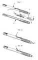
- FIG. 1illustrates an exploded view of a related art safety knife with a retractable guard
- FIGS. 2A and Brespectively illustrate the safety knife of FIG. 1 with the guard in retracted and extended positions
- FIG. 3illustrates an exploded view of a retractable safety knife according to a first embodiment of the present invention
- FIGS. 4A and Brespectively illustrate the retractable safety knife of FIG. 3 in blade-extended and blade-retracted positions
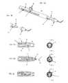
- FIGS. 5A and Billustrate top and bottom views of a base of the safety knife of FIG. 3 ;
- FIGS. 6A and Billustrate top and bottom views of a cover of the safety knife of FIG. 3 ;
- FIG. 7Aillustrates a pusher of the safety knife of FIG. 3
- FIG. 7Billustrates a pusher according to another embodiment of the present invention
- FIG. 8Aillustrates cutaway and end views of an end of a handle of the safety knife of FIG. 3 ;
- FIG. 8Billustrates cutaway and end views of the pusher, a blade, and the end of the handle of the safety knife of FIG. 3 in the blade-extended and extended positions;
- FIG. 8Cillustrates cutaway and end views of the pusher, the blade, and the end of the handle of the safety knife of FIG. 3 in the blade-retracted and nested positions;
- FIG. 9Aillustrates enlarged cutaway and end views of the pusher, the blade, and the end of the handle of the retractable safety knife of FIG. 3 between the blade-extended/extended positions and blade-retracted/nested positions;
- FIG. 9Billustrates enlarged cutaway and end views of the pusher, the blade, and the end of the handle of the retractable safety knife of FIG. 3 in the blade-retracted and nested positions;
- FIG. 10illustrates a cutaway view of a modified tilt track according to a second embodiment of the present invention
- FIG. 11Aillustrates a cutaway view of the handle and the head showing an annular groove and an annular protrusion according to a third embodiment of the present invention
- FIG. 11Billustrates a cutaway view of the handle and the head showing an annular groove and an annular protrusion according to another embodiment of the present invention
- FIGS. 12A 12 Eillustrate a modified pusher of a safety knife according to a fourth embodiment of the present invention, and an interaction of a slot of the pusher with an alignment pin of the handle;
- FIGS. 13A and 13Brespectively illustrate safety knife 10 of FIG. 1 and retractable safety knife 40 of FIG. 3 in position for a typical clear corneal incision.
- FIGS. 1 , 2 A, and 2 BA device in accordance with the last-mentioned application is shown in FIGS. 1 , 2 A, and 2 B.
- FIG. 1illustrates an exploded view of a safety knife with a retractable guard
- FIGS. 2A and Brespectively illustrate the safety knife of FIG. 1 with the guard in retracted and extended positions.
- the safety knife 10includes a cover 12 and a base 14 , which together form a hollow handle 16 .
- the base 14includes a blade 18 , which in the illustrated embodiment is a bent blade.
- a pusher 20is disposed within the handle 16 , and includes a shield or guard 22 , which selectively covers the blade 18 , and a button 24 , which extends through slot 26 of cover 12 .
- the guard 22includes an enlarged distal end 28 , due to the angled nature of the bent blade 18 .
- guard 22slides forward so that enlarged distal end 28 covers the blade 18 , thereby protecting a user from an accidental injury, and protecting the blade 18 .
- the safety knife 10accomplishes these goals, in the extended position, it may be possible to deflect the guard 22 into the blade. Further, while the enlarged distal end 28 may be made of a transparent material, the curved surface may distort a surgeon's view of the blade 18 (see, e.g., FIG. 13B ).
- FIG. 3illustrates an exploded view of a retractable safety knife according to an embodiment of the present invention.
- FIGS. 4A and Brespectively illustrate the retractable safety knife of FIG. 3 in blade-extended and blade-retracted positions.
- retractable safety knife 40includes a cover 42 , a base 44 , a pusher 46 , and a blade 48 .
- the cover 42 and the base 44are ultrasonically welded together to form a handle 50 .
- the retractable safety knife 40is distributed as a product with the pusher 46 and blade 48 in the retracted or safe position.
- FIGS. 5A and Billustrate top and bottom views of base 44 .
- FIGS. 6A and Billustrate top and bottom views of cover 42 .
- cover 42has a plurality of alignment pins 90 and base 44 has a corresponding plurality of alignment holes or alignment bushings 92 .
- the alignment pins 90are inserted into the alignment bushings 92 to align the cover 42 and the base 44 to form the handle 50 .
- alignment pins 90are disposed on base 44 , and alignment bushings 92 are disposed on cover 42 , According to yet another embodiment, alignment pins 90 and alignment bushings 92 are disposed on base 44 , and corresponding alignment bushings 92 and alignment pins 90 are disposed on cover 42 .
- the handle 50is substantially cylindrical, and is hollow to define a chamber therein. Additionally, as best shown in FIG. 4B , handle 50 has an opening 52 at a distal end thereof, and a slot or opening 54 that extends along a longitudinal axis of the handle 50 and accesses the chamber. As shown in FIG. 4B , according to one embodiment, the opening 52 is substantially circular. Slot 54 has detents 56 and 58 , corresponding, respectively, to the blade-extended and blade-retracted positions. According to one embodiment, detents 56 and 58 are each formed as respective pairs disposed on opposing transverse sides of the slot 54 (see, e.g., FIG. 13B )
- the pusher 46is disposed substantially within the handle 50 to slide within the chamber, and has a button 60 disposed on a top of a main portion or beam 64 thereof, corresponding with the slot 54 .
- Button 60has a projection or button stop 62 disposed on a side thereof.
- projection 62is one of a pair of projections disposed on opposing sides of button 60 .
- the projection 62selectively engages the detents 56 and 58 to secure the pusher 46 (and the blade 48 , as will be discussed in greater detail below) in the blade-retracted and blade-extended positions.
- the projection 62is designed to ease disengagement with the detents 56 or 58 .
- the userdepresses the button 60 (pushing inwardly with respect to the handle 50 ) to disengage from the current detent. Then, the user slides the button 60 to advance it toward the target detent, and there is an audible click, as the projection 62 snaps into the target detent, to confirm positioning therein.
- the usermoves the button 60 sideways to disengage the projection from a detent, either 56 or 58 , (thereby elastically deforming the projection 62 and/or the handle 50 ) and slides the button 60 to advance it toward the target detent.
- the positioning of the detents and the projectionis reversed, i.e., the slot 54 has projections corresponding, respectively, to the blade-extended and blade-retracted positions, and the button has a detent that selectively engages the projections.
- FIG. 7Aillustrates the pusher 46 of the safety knife 40 .
- a tilt beam 66made of plastic, metal, or other rigid, but resilient material extends from an end of the main portion 64 of the pusher 46 , and the blade 48 is connected with an end of the tilt beam 66 .
- the tilt beamhas a tilt pin 70 disposed thereon.
- the bladeis connected with a first end of a head 68 , and a second end of the head, opposite to the first end, is connected with the tilt beam 66 .
- the blade 48can be connected with the head 68 in any desired manner, e.g., by being glued, press fitted, snapped, screwed, and/or molded to the head 68 .
- the head 68is detachable from the tilt beam 66 .
- the head 68can be connected with the tilt beam 66 by being glued, press fitted, snapped, and/or screwed to the tilt beam 66 .
- FIG. 8Aillustrates cutaway and end views of an end of the handle 50 .
- FIG. 8Billustrates cutaway and end views of the pusher 46 , the blade 48 , and the end of the handle 50 in the blade-extended and extended positions.
- FIG. 8Cillustrates cutaway and end views of the pusher 46 , the blade 48 , and the end of the handle 50 in the blade-retracted and nested positions.
- FIG. 9Aillustrates enlarged cutaway and end views of the pusher 46 , the blade 48 , and the end of the handle 50 between the blade-extended/extended positions and blade-retracted/nested positions.
- FIG. 9Billustrates enlarged cutaway and end views of the pusher 46 , the blade 48 , and the end of the handle 50 in the blade-retracted and nested positions.
- the handle 50includes a tilt track 72 , which may alternately be referred to as a cam track or tilt slot.
- a tilt track 72which may alternately be referred to as a cam track or tilt slot.
- respective portions of the tilt track 72are molded in the base 44 and cover 42 during manufacture thereof.
- respective portions of the tilt track 72are milled in the base 44 and cover 42 during manufacture thereof.
- the tilt track 72defines an inclined (i.e., with respect to the handle axis) guide path for the tilt pin 70 .
- the tilt pin 70is engaged with tilt track 72 .
- the handle 50has a pair of tilt tracks 72 on opposing sides of the chamber, to guide opposing ends of the tilt pin 70 .
- the tilt pin 70is forced upward by riding in the tilt track 72 .
- the tilt pin 70is forced up the tilt beam 66 is deflected, that is, its shape is changed, such as by deformation (preferably elastic deformation) of the tilt beam 66 , as shown in FIGS.
- FIGS. 9A and 9Brespectively show the head 68 and the blade 48 in the nested position between the blade-extended and blade-retracted positions, and in the blade-retracted/nested positions.
- the guide path of tilt track 72preferably includes a first guide path portion 74 and a second guide path portion 76 .
- the first guide path portion 74is inclined at an angle of about 5-10° with respect to the substantially linear travel path of the main portion 64 of the pusher 46 .
- the first guide path portion 74is inclined at an angle of about 6.24° with respect to the substantially linear travel path of the main portion 64 of the pusher 46 .
- the second guide path portion 76adjoins the first guide path portion 74 and is substantially parallel to the travel path of the main portion 64 .
- tilt track 72(and in the specific case of the embodiment of FIG. 8A , the angle of the first guide path portion 74 ) dictates how fast and far the head 68 and blade 48 move.
- the tip of blade 48dives down towards the handle's 50 centerline during retraction.
- embodiments of the present inventionare not limited to the first and second guide paths 74 and 76 shown in FIG. 8A .
- tilt track 72 Ais curvilinear.
- the blade 48 shown, for example, in FIGS. 3-9Bis depicted as being a round stock blade about 3.2 mm in width and having a bend height of about 0.205 inches (about 5.2 mm). These are substantially the same dimensions as the blade 18 that is depicted in FIGS. 1 , 2 A, and 2 B.
- the retractable safety knife 40With the retractable safety knife 40 however, as shown, e.g., in FIGS. 9A and 9B , such a blade achieves a tip clearance 73 of about 0.039 inches and a side clearance 75 of about 0.031 inches when in the nested and blade-retracted/nested positions.
- a guarddoes not have to be accommodated within the chamber of handle 50 , even if an internal diameter handle 50 is the same as that of handle 16 , a larger blade can be accommodated within handle 50 .
- a blade approximately 4.0 mm wide, with a bend height increase of 0.02 inches (total of about 0.225 inches)can be accommodated within handle 50 .
- embodiments of the present inventionare not limited to the above-described blades, and that differently sized blades may be employed. Additionally, it will be understood that flat stock blades may be employed.
- a portion of the head 68has a cylindrical diameter that has minimal clearance with respect to a bore of the chamber of the handle 50 . Additionally, as shown in FIGS. 8A and 8B , when the pusher 46 is moved from the blade-retracted position to the blade-extended position, the tilt pin 70 crosses the longitudinal centerline of the handle 50 , tensioning the tilt beam 66 .
- the handle 50has an annular groove 78
- the head 68has an annular protrusion 79 .
- the annular protrusion 79positively engages the annular groove 78 , to stabilize the blade 48 in the extended position.
- the handle 50has the annular protrusion 79 and the head 68 has the annular groove 78 .
- the main portion 64 of the pusher 46has a slot 80 therein extending along a longitudinal axis of the pusher 46 , the slot having detents 82 and 84 corresponding to the blade-extended and blade-retracted positions.
- the handle 50has an inwardly-directed alignment pin 86 (see FIGS. 12B-12E ) that is stationary and engages the pusher slot 80 when the safety knife 40 is assembled. Beginning, for example, at the blade-retracted position ( FIG. 12B ), as the pusher 46 is moved ( FIG. 12C ) to the blade-extended position ( FIG. 12D ), the slot 80 moves relative to the alignment pin 86 .
- the alignment pindoes not fully engage the detent 82 , thereby creating a force that urges the pusher 46 toward the blade-extended position.
- a portion of the alignment pin 86is still engaged with a constricted portion of the slot 80 disposed between the detents 82 and 84 . Because the constricted portion of the slot 80 elastically deforms during relative passage of the alignment pin 86 therethrough (as shown, for example, in FIG.
- the portion of the alignment pin 86 still engaged with the constricted portion of the slot 80 when the pusher 46 is moved to the blade-extended positionelastically deforms the end of the constricted portion adjacent to the detent 82 .
- the constricted portion of the slot 80exerts a force relative to the alignment pin 86 to bias the alignment pin 86 toward the detent 82 , and thereby urge the pusher 46 toward the blade-extended position.
- FIGS. 13A and 13Brespectively illustrate related art safety knife 10 and retractable safety knife 40 in position for a typical clear corneal incision.
- the configuration of retractable safety knife 40provides a clear view of the blade 48 for a surgeon, whereas in contrast, the enlarged distal end 28 of related art safety knife 10 ( FIG. 13A ) may partially obscure the view of blade 18 .
- the enlarged distal end 28may be made of a transparent material, the curved surface may distort a surgeon's view of the blade 18 .
Landscapes
- Health & Medical Sciences (AREA)
- Life Sciences & Earth Sciences (AREA)
- Surgery (AREA)
- Veterinary Medicine (AREA)
- Engineering & Computer Science (AREA)
- Biomedical Technology (AREA)
- Heart & Thoracic Surgery (AREA)
- Animal Behavior & Ethology (AREA)
- General Health & Medical Sciences (AREA)
- Public Health (AREA)
- Nuclear Medicine, Radiotherapy & Molecular Imaging (AREA)
- Ophthalmology & Optometry (AREA)
- Medical Informatics (AREA)
- Molecular Biology (AREA)
- Vascular Medicine (AREA)
- Surgical Instruments (AREA)
Abstract
Description
Claims (20)
Priority Applications (5)
| Application Number | Priority Date | Filing Date | Title |
|---|---|---|---|
| US12/068,494US8464430B2 (en) | 2008-02-07 | 2008-02-07 | Retractable safety knife |
| CA2652749ACA2652749C (en) | 2008-02-07 | 2009-02-05 | Retractable safety knife |
| EP09152288.8AEP2087845B1 (en) | 2008-02-07 | 2009-02-06 | Retractable Safety Knife |
| JP2009027174AJP5149216B2 (en) | 2008-02-07 | 2009-02-09 | Retractable safety knife |
| US12/929,016US9044265B2 (en) | 2008-02-07 | 2010-12-22 | Retractable safety knife |
Applications Claiming Priority (1)
| Application Number | Priority Date | Filing Date | Title |
|---|---|---|---|
| US12/068,494US8464430B2 (en) | 2008-02-07 | 2008-02-07 | Retractable safety knife |
Related Child Applications (1)
| Application Number | Title | Priority Date | Filing Date |
|---|---|---|---|
| US12/929,016ContinuationUS9044265B2 (en) | 2008-02-07 | 2010-12-22 | Retractable safety knife |
Publications (2)
| Publication Number | Publication Date |
|---|---|
| US20090204135A1 US20090204135A1 (en) | 2009-08-13 |
| US8464430B2true US8464430B2 (en) | 2013-06-18 |
Family
ID=40602429
Family Applications (2)
| Application Number | Title | Priority Date | Filing Date |
|---|---|---|---|
| US12/068,494Active2028-10-27US8464430B2 (en) | 2008-02-07 | 2008-02-07 | Retractable safety knife |
| US12/929,016ActiveUS9044265B2 (en) | 2008-02-07 | 2010-12-22 | Retractable safety knife |
Family Applications After (1)
| Application Number | Title | Priority Date | Filing Date |
|---|---|---|---|
| US12/929,016ActiveUS9044265B2 (en) | 2008-02-07 | 2010-12-22 | Retractable safety knife |
Country Status (4)
| Country | Link |
|---|---|
| US (2) | US8464430B2 (en) |
| EP (1) | EP2087845B1 (en) |
| JP (1) | JP5149216B2 (en) |
| CA (1) | CA2652749C (en) |
Cited By (9)
| Publication number | Priority date | Publication date | Assignee | Title |
|---|---|---|---|---|
| US20110098734A1 (en)* | 2008-02-07 | 2011-04-28 | Dana Michael Cote | Retractable safety knife |
| US20120215241A1 (en)* | 2010-04-09 | 2012-08-23 | Oasis Medical, Inc. | Micro surgical knife with safety feature |
| US20130158574A1 (en)* | 2010-06-28 | 2013-06-20 | Medipurpose Pte Ltd. | Safety Scalpel |
| US20140157604A1 (en)* | 2011-02-10 | 2014-06-12 | Samuel George | Hand-held cutting implements |
| US20150073449A1 (en)* | 2010-04-21 | 2015-03-12 | Ravi Nallakrishnan | Safety Knife With Retractable And Extendable Blade And Guard |
| US20160249947A1 (en)* | 2015-02-27 | 2016-09-01 | Medipurpose Pte Ltd | Safety Scalpel with Replaceable Blade Cartridge |
| US9901367B2 (en)* | 2014-03-05 | 2018-02-27 | Spectra Medical Devices, Inc. | Safety scalpel |
| US20180125520A1 (en)* | 2015-06-03 | 2018-05-10 | Surgical Specialties Corporation | Retractable knife |
| US11109886B2 (en)* | 2004-10-20 | 2021-09-07 | Beaver-Visitec International (Us), Inc. | Surgical knife safety handle having user operable lock |
Families Citing this family (26)
| Publication number | Priority date | Publication date | Assignee | Title |
|---|---|---|---|---|
| US7022128B2 (en) | 2003-04-22 | 2006-04-04 | Becton, Dickinson And Company | Surgical knife safety handle |
| US7434317B2 (en)* | 2004-09-23 | 2008-10-14 | Irwin Industrial Tool Company | Slide assembly device for a snap-off blade utility knife |
| US20100217297A1 (en)* | 2009-02-26 | 2010-08-26 | Anita Nevyas-Wallace | Surgical Knife Providing Enhanced Blade Visualization |
| PT2475342T (en)* | 2009-09-10 | 2020-06-25 | Core Surgical Ltd | Surgical knife handle and knife |
| JP4730920B2 (en)* | 2009-11-26 | 2011-07-20 | 正一 中村 | Medical knife |
| USD639432S1 (en)* | 2010-08-31 | 2011-06-07 | Oasis Medical, Inc. | Handle for use with a micro surgical knife |
| USD642682S1 (en)* | 2010-05-21 | 2011-08-02 | Surgistar, Inc. | Retractable surgical safety knife |
| DK2941209T3 (en)* | 2013-01-07 | 2020-01-06 | Taryag Medical Ltd | Expandable atherectomy device |
| US9968372B2 (en)* | 2013-10-02 | 2018-05-15 | Medical Instrument Development Laboratories, Inc. | Cannula insertion tool |
| JP6563940B2 (en)* | 2014-02-06 | 2019-08-21 | ノバルティス アーゲー | Manufacture of articulating ophthalmic surgical probes |
| USD750780S1 (en) | 2014-02-18 | 2016-03-01 | Mani, Inc. | Surgical knife |
| WO2015129461A1 (en)* | 2014-02-28 | 2015-09-03 | マニー株式会社 | Medical knife |
| USD740421S1 (en)* | 2014-08-29 | 2015-10-06 | Osteomed Llc | Surgical knife |
| US9629747B2 (en) | 2014-09-17 | 2017-04-25 | Iantech, Inc. | Devices and methods for cutting lenticular tissue |
| CN112826657B (en) | 2014-09-17 | 2023-10-17 | 卡尔蔡司白内障医疗技术公司 | Device and method for removing lens tissue |
| US10555755B2 (en) | 2015-03-27 | 2020-02-11 | Richard S. Werner | Retractable device |
| US10624785B2 (en) | 2016-01-30 | 2020-04-21 | Carl Zeiss Meditec Cataract Technology Inc. | Devices and methods for ocular surgery |
| AU2017232627B2 (en)* | 2016-03-17 | 2021-07-29 | Carl Zeiss Meditec Cataract Technology Inc. | Devices and methods for cutting lenticular tissue |
| CA3041813A1 (en) | 2016-10-26 | 2018-05-03 | Carl Zeiss Meditec Cataract Technology Inc. | Methods and devices for cutting a lens in an eye |
| JP6820214B2 (en)* | 2017-03-02 | 2021-01-27 | 株式会社貝印刃物開発センター | Medical knife |
| US11141188B2 (en) | 2017-11-10 | 2021-10-12 | Andrea CHINI | Safety scalpel |
| JP7312177B2 (en) | 2017-12-14 | 2023-07-20 | カール・ツァイス・メディテック・キャタラクト・テクノロジー・インコーポレイテッド | Apparatus and method for ophthalmic surgery |
| CN112089478B (en)* | 2020-09-08 | 2025-07-04 | 上海瑛泰医疗器械股份有限公司 | A joint intervention device and system thereof |
| CN113100886B (en)* | 2021-03-23 | 2022-05-24 | 张宾 | Cutting knife with function of preventing accidental touch for hospital |
| WO2024261583A1 (en)* | 2023-06-22 | 2024-12-26 | Alcon Inc. | Surgical knife with retractable blade |
| US20240423662A1 (en)* | 2023-06-22 | 2024-12-26 | Alcon Inc. | Surgical round knife with adjustable blade |
Citations (121)
| Publication number | Priority date | Publication date | Assignee | Title |
|---|---|---|---|---|
| US1195169A (en) | 1916-08-22 | Masvin e | ||
| US1914153A (en) | 1931-09-08 | 1933-06-13 | John J Ogden | Surgical knife |
| US2207296A (en) | 1940-03-11 | 1940-07-09 | Albert D Lee | Refillable typewriter eraser |
| US2304332A (en) | 1939-11-10 | 1942-12-08 | Conrad Razor Blade Co Inc | Scraping device |
| US2409589A (en)* | 1945-08-29 | 1946-10-15 | Cons Vultee Aircraft Corp | Rivet removing device |
| US2512237A (en) | 1948-03-12 | 1950-06-20 | Edward E Mravik | Pocket implement |
| US2885780A (en) | 1957-12-03 | 1959-05-12 | Floyd A Campbell | Marking tool |
| US2885779A (en)* | 1957-12-13 | 1959-05-12 | Gadget Of The Month Club Inc | Penknife clipper |
| US2896317A (en)* | 1958-03-28 | 1959-07-28 | Vaive Victor Alex | Bottle seal cutter |
| US3002273A (en)* | 1960-09-12 | 1961-10-03 | Earl L Merritt | Carton opening tool |
| US3176395A (en)* | 1963-12-27 | 1965-04-06 | David H Warner | Photoengraver's saber |
| US3518758A (en)* | 1967-10-24 | 1970-07-07 | Robert A Bennett | Utility knife with movable and rotatable blade |
| US3706106A (en) | 1971-01-18 | 1972-12-19 | Norbert Leopoldi | Surgical knife |
| US3905101A (en) | 1974-04-19 | 1975-09-16 | Becton Dickinson Co | Disposable surgical scalpel |
| US3906626A (en) | 1974-04-19 | 1975-09-23 | Becton Dickinson Co | Disposable surgical scalpel |
| US3943627A (en) | 1973-11-28 | 1976-03-16 | Stanley Jr Conrad | Front loading utility knife |
| US3967377A (en) | 1975-03-17 | 1976-07-06 | Wells Royzell F | Precision positioning device for tool blades and the like |
| US4091537A (en) | 1977-04-26 | 1978-05-30 | Stevenson Machine Shop | Safety utility knife |
| US4096629A (en)* | 1977-05-16 | 1978-06-27 | Levine Alfred B | Multiple bladed retractable claw weapon |
| US4167811A (en)* | 1978-03-13 | 1979-09-18 | Imperial Knife Associated Companies, Inc. | Folding knife |
| US4265017A (en)* | 1979-09-07 | 1981-05-05 | Jenkins Metal Corporation | Pocket knife with retractable blade |
| US4356631A (en)* | 1980-10-15 | 1982-11-02 | Guth Kenneth W | Foldable push dagger |
| US4375218A (en) | 1981-05-26 | 1983-03-01 | Digeronimo Ernest M | Forceps, scalpel and blood coagulating surgical instrument |
| US4393587A (en) | 1981-04-23 | 1983-07-19 | Kloosterman William A | Spring shielded safety knife |
| US4414974A (en) | 1981-06-09 | 1983-11-15 | General Conveyors Limited | Microsurgical knife |
| US4491132A (en) | 1982-08-06 | 1985-01-01 | Zimmer, Inc. | Sheath and retractable surgical tool combination |
| US4499898A (en) | 1982-08-23 | 1985-02-19 | Koi Associates | Surgical knife with controllably extendable blade and gauge therefor |
| US4500220A (en) | 1982-09-20 | 1985-02-19 | Pentel Kabushiki Kaisha | Mechanical pencil with removable lead feed cover |
| US4516575A (en) | 1982-06-03 | 1985-05-14 | Coopervision, Inc. | Surgical scalpel |
| US4523379A (en) | 1984-05-02 | 1985-06-18 | Tekna | Knife with retractable sheath |
| US4538356A (en) | 1982-08-23 | 1985-09-03 | Koi Associates, Inc. | Surgical knife with controllably extendable blade and gauge therefor |
| US4576164A (en) | 1983-11-14 | 1986-03-18 | Richeson W George | Knife with locking shroud |
| US4630378A (en) | 1985-06-13 | 1986-12-23 | Pilling Co. | Gauge for extensible-blade surgical knife |
| US4660287A (en) | 1985-11-01 | 1987-04-28 | Decker John R | Knife with replaceable blade |
| US4662075A (en) | 1985-08-22 | 1987-05-05 | Magnum Diamond Reclamation, Inc. | Apparatus and method for setting knife blade depth |
| US4719915A (en) | 1985-05-05 | 1988-01-19 | Michael Porat | Scalpel |
| US4735202A (en) | 1986-10-06 | 1988-04-05 | Alcon Laboratories, Inc. | Microsurgical knife with locking blade guard |
| US4757612A (en) | 1985-03-21 | 1988-07-19 | Preposreve S.A.R.L. | Fixed-blade knife with retractable blade cover |
| DE3722899A1 (en) | 1987-07-08 | 1989-01-19 | Peters Tim | Scalpel |
| US4815218A (en) | 1986-06-13 | 1989-03-28 | Cilco, Inc. | Gauge for calibrating surgical scalpel |
| US4823457A (en) | 1988-04-20 | 1989-04-25 | American Safety Razor Company | Disposable surgical scalpel |
| US4825545A (en) | 1986-03-18 | 1989-05-02 | Sabre International Products Limited | Knives with molded protective cover and handle |
| US4826339A (en) | 1987-02-06 | 1989-05-02 | Pentel Kabushiki Kaisha | Dispenser having a flexible nib, slidable sleeve and cap |
| US4910821A (en) | 1989-04-24 | 1990-03-27 | Kieferle Ralph M | Screen installers tool |
| US4958625A (en) | 1989-07-18 | 1990-09-25 | Boston Scientific Corporation | Biopsy needle instrument |
| US4985034A (en) | 1989-06-01 | 1991-01-15 | Board Of Regents, The University Of Texas System | Safety surgical blade, handle and shield |
| US5015252A (en) | 1990-08-13 | 1991-05-14 | Jones Mark W | Surgical forceps with suture cutters |
| US5035703A (en) | 1990-05-09 | 1991-07-30 | Baskas Morris J | Disposable syringe needle and scalpel holder |
| US5071426A (en) | 1989-04-06 | 1991-12-10 | Stuart Dolgin | Surgical scalpel with retractable blade guard |
| US5139507A (en) | 1989-04-06 | 1992-08-18 | Stuart Dolgin | Surgical scalpel with retractable blade guard |
| US5203865A (en) | 1990-08-23 | 1993-04-20 | Siepser Steven B | Surgical knives for use in ophthalmic surgery |
| US5207696A (en) | 1992-04-30 | 1993-05-04 | Medical Sterile Products, Inc. | Surgical scalpel |
| US5222951A (en) | 1992-04-13 | 1993-06-29 | Leonard Bloom | Guarded skin hook for surgical use |
| EP0555196A1 (en) | 1992-01-24 | 1993-08-11 | Michael R. Abidin | Surgical scalpel with retractable guard |
| US5254128A (en) | 1990-10-11 | 1993-10-19 | Micro Engineering, Inc. | Surgical knife with attached, movable blade protector |
| US5292329A (en) | 1992-12-04 | 1994-03-08 | Werner Richard S | Retractable surgical knife |
| US5299357A (en) | 1991-12-18 | 1994-04-05 | American Safety Razor Company | Disposable surgical scalpel with safety guard |
| US5309641A (en) | 1991-12-18 | 1994-05-10 | American Safety Razor Company | Disposable surgical scalpel with safety guard |
| US5312429A (en) | 1992-07-27 | 1994-05-17 | Devon Industries, Inc. | Scalpel handle and blade release assembly |
| US5330493A (en) | 1992-11-27 | 1994-07-19 | Haining Michael L | Disposable scalpel |
| US5330492A (en) | 1992-10-21 | 1994-07-19 | Dlh Concepts, Inc. | Safety scalpel |
| US5336235A (en) | 1991-07-23 | 1994-08-09 | Myers William D | Keratome |
| US5344424A (en) | 1993-03-12 | 1994-09-06 | Roberts Philip L | Selectively retractable, disposable surgical knife |
| US5361902A (en) | 1992-06-05 | 1994-11-08 | Leonard Bloom | Surgical blade dispenser and disposal system for use during an operating procedure and method thereof |
| US5370654A (en) | 1993-06-18 | 1994-12-06 | Leonard Bloom | Disposable guarded finger scalpel for inserting a line in a patient and method of use thereof |
| US5411512A (en) | 1992-01-24 | 1995-05-02 | Leonard Bloom | Guarded surgical scalpel |
| US5431672A (en) | 1994-05-09 | 1995-07-11 | Becton, Dickinson And Company | Surgical scalpel with retractable blade |
| US5431671A (en)* | 1993-05-28 | 1995-07-11 | Nallakrishnan; Ravi | Surgical knife with retractable and angularly adjustable blade |
| US5433321A (en) | 1994-05-18 | 1995-07-18 | Bloom & Kreten | Article and method for safely mounting a blade on a surgical scalpel |
| US5496340A (en) | 1992-01-24 | 1996-03-05 | Leonard Bloom | Combination guarded surgical scalpel and blade stripper |
| US5545175A (en) | 1993-06-18 | 1996-08-13 | Leonard Bloom | Disposable quarded finger scalpel for inserting a line in a patent and lock off therefor |
| US5571128A (en)* | 1995-07-24 | 1996-11-05 | Shapiro; Henry | Safety surgical instrument |
| US5577850A (en) | 1992-07-31 | 1996-11-26 | Pentel Kabushiki Kaisha | Rodlike body feeding device |
| US5601572A (en) | 1989-08-16 | 1997-02-11 | Raychem Corporation | Device or apparatus for manipulating matter having a elastic ring clip |
| US5613300A (en) | 1993-01-12 | 1997-03-25 | Pacific Handy Cutter | Ergonomic utility knife/box cutter and method of making |
| US5620454A (en) | 1994-10-25 | 1997-04-15 | Becton, Dickinson And Company | Guarded surgical scalpel |
| US5662221A (en) | 1994-05-18 | 1997-09-02 | Bloom & Kreten | Low-cost safe blade package for surgical purposes |
| US5665099A (en) | 1995-05-12 | 1997-09-09 | Pilo; Giuseppe | Surgical scalpel with automatically retractable blade |
| US5664668A (en) | 1994-09-14 | 1997-09-09 | Motorola, Inc. | Tactile button with snapped on pivot and deflecting mechanism |
| US5683407A (en) | 1995-10-19 | 1997-11-04 | Becton, Dickinson And Company | Cleanable guarded surgical scalpel with scalpel blade remover |
| USD386526S (en) | 1995-01-27 | 1997-11-18 | Pentel Kabushiki Kaisha | Holder for a rubber eraser |
| US5727682A (en) | 1994-05-18 | 1998-03-17 | Bloom & Kreten | Low-cost safe blade package for surgical purposes |
| US5749886A (en) | 1993-06-18 | 1998-05-12 | Leonard Bloom | Disposable guarded finger scalpel for inserting a line in a patient and blade therefor |
| US5827309A (en) | 1994-10-25 | 1998-10-27 | Becton, Dickinson And Company | Guarded surgical scalpel with scalpel blade remover |
| US5891105A (en)* | 1993-08-23 | 1999-04-06 | Mahurkar; Sakharam D. | Hypodermic needle assembly |
| US5893845A (en)* | 1996-06-21 | 1999-04-13 | Becton Dickinson & Company | Telescoping needle shield |
| US5908432A (en) | 1998-03-27 | 1999-06-01 | Pan; Huai C. | Scalpel with retractable blade |
| US5919201A (en) | 1993-12-08 | 1999-07-06 | Becton, Dickinson And Company | Surgical scalpel |
| US5924206A (en) | 1997-09-30 | 1999-07-20 | Becton, Dickinson And Company | Reusable device handle |
| USD421303S (en) | 1998-09-30 | 2000-02-29 | Becton, Dickinson And Company | Surgical knife handle |
| US6065889A (en) | 1995-01-30 | 2000-05-23 | Pentel Kabushiki Kaisha | Side-knock type mechanical pencil |
| US6079106A (en)* | 1999-09-28 | 2000-06-27 | Vallotton; Alney K. | Knife blade locking mechanism |
| US6089775A (en) | 1997-01-31 | 2000-07-18 | Pentel Kabushiki Kaisha | Retractable-lead mechanical pencil |
| US6145202A (en)* | 1998-03-10 | 2000-11-14 | Kai U.S.A. Ltd. | Opening and closing assisting mechansim for folding knife |
| US6308420B1 (en)* | 2000-06-17 | 2001-10-30 | Taylor Cutlery Llc | Folding knife with spring and cam |
| US20020065532A1 (en) | 2000-11-29 | 2002-05-30 | Lewis Harrold | Keratome blade holder |
| US20020143352A1 (en) | 2001-03-29 | 2002-10-03 | Newman Craig D. | Shielded surgical scalpel |
| US6569175B1 (en) | 2001-11-14 | 2003-05-27 | Alcon, Inc. | Surgical knife |
| US20030225428A1 (en) | 2002-05-30 | 2003-12-04 | Kai R&D Center Co., Ltd. | Surgical knife |
| US20040040159A1 (en)* | 2001-07-23 | 2004-03-04 | Gregory Fossella | Utility knife |
| USD496730S1 (en) | 2003-03-17 | 2004-09-28 | Becton, Dickinson & Company | Surgical knife safety handle |
| US20040215174A1 (en) | 2003-04-22 | 2004-10-28 | Morawski Michael J. | Surgical knife safety handle |
| US20050015104A1 (en) | 2003-04-22 | 2005-01-20 | Morawski Michael J. | Surgical knife safety handle |
| US6884240B1 (en) | 2001-12-07 | 2005-04-26 | Ronald Dykes | Protection system for surgical instruments |
| US20050138816A1 (en)* | 2002-12-10 | 2005-06-30 | Great Neck Saw Manufacturers, Inc. | Utility knife |
| US6948250B1 (en) | 2003-03-06 | 2005-09-27 | Caiafa Jr Gerard | Retractable/disposable craft knife and blade insert therefor |
| US20050267502A1 (en) | 2003-12-18 | 2005-12-01 | Hochman Mark N | Disposable safety cutting tool |
| US7028406B2 (en)* | 2003-06-04 | 2006-04-18 | Martor Kg | Deburring tool with replaceable blade |
| US20060085019A1 (en) | 2004-10-20 | 2006-04-20 | Becton, Dickinson And Company | Surgical knife safety handle having user operable lock |
| US7055248B2 (en) | 2004-04-30 | 2006-06-06 | Becton, Dickinson And Company | Surgical knife blade attachment and method for using same |
| US7059053B2 (en)* | 2000-11-07 | 2006-06-13 | Kimi Sakai | Folding knife with blade lock |
| US7121005B2 (en)* | 2002-07-31 | 2006-10-17 | Mark Hughes | Hand held device comprising a handle and an operational member which folds into and out of a side of the handle |
| US7146736B1 (en)* | 2004-08-30 | 2006-12-12 | Collins Walter W | Folding knife with cantilevered spring |
| USD537528S1 (en) | 2005-06-22 | 2007-02-27 | Oasis Medical, Inc. | Guarded blade assembly |
| US7185435B1 (en)* | 2005-11-09 | 2007-03-06 | Awi Acquisition Company | Utility knife with dual blades |
| US7284329B1 (en)* | 2004-12-16 | 2007-10-23 | Randall King Knives, Inc. | Folding knife with cantilevered retainer |
| US7520059B2 (en)* | 2005-08-02 | 2009-04-21 | The Stanley Works | Compact utility knife |
| US20090113720A1 (en)* | 2007-11-07 | 2009-05-07 | Delillo Dominick D | Utility Knife |
| US20090204136A1 (en)* | 2006-09-08 | 2009-08-13 | Kai R&D Center Co., Ltd. | Hand Tool |
| US7797836B2 (en)* | 2005-08-02 | 2010-09-21 | The Stanley Works | Compact utility knife |
| USD642682S1 (en) | 2010-05-21 | 2011-08-02 | Surgistar, Inc. | Retractable surgical safety knife |
Family Cites Families (29)
| Publication number | Priority date | Publication date | Assignee | Title |
|---|---|---|---|---|
| US3192624A (en)* | 1963-10-30 | 1965-07-06 | Allway Mfg Co Inc | Knife handle with adjustable blade |
| US3383763A (en) | 1966-06-29 | 1968-05-21 | Helge J. Strandfors | Razor with replaceable blade |
| USD283544S (en) | 1982-12-23 | 1986-04-22 | Sharpoint Inc. | Surgical knife handle |
| US5779724A (en)* | 1992-12-04 | 1998-07-14 | Werner; Richard S. | Retractable surgical knife |
| US5330494A (en) | 1993-01-22 | 1994-07-19 | Cornelis A. van der Westhuizen | Knife |
| US5342379A (en) | 1993-06-01 | 1994-08-30 | Volinsky Fredric G | Safety scalpel |
| US5599351A (en)* | 1993-12-08 | 1997-02-04 | Habley Medical Technology Corporation | Scalpels having permanent blade retraction |
| US5938676A (en)* | 1993-12-08 | 1999-08-17 | Becton, Dickinson & Company | Surgical scalpel |
| US5475925A (en) | 1994-03-21 | 1995-12-19 | Newman; Philip H. | Three-piece retractable-bladed knife |
| US5571127A (en)* | 1995-03-08 | 1996-11-05 | Decampli; William M. | Scalpel handle having retractable blade support and method of use |
| FR2767469B1 (en)* | 1997-08-25 | 2000-06-16 | Raphael Mosseri | PROTECTION DEVICE FOR A CUTTING AND / OR PERFORATING TOOL |
| US6048354A (en)* | 1999-02-01 | 2000-04-11 | Lawrence; Jeffrey M. | Sliding knife and needle assembly for making a portal for endoscopic or arthroscopic surgery |
| AU712212B3 (en) | 1999-07-15 | 1999-10-28 | Occupational & Medical Innovations Ltd | A surgical scalpel with retractable guard |
| US6112420A (en) | 1999-08-10 | 2000-09-05 | S-B Power Tool Company | Blade clamp for reciprocating saw |
| US6503262B1 (en) | 2000-07-19 | 2003-01-07 | Escalon Medical Corporation | Retractable micro-surgical tool |
| US6391041B1 (en) | 2000-07-19 | 2002-05-21 | Escalon Medical Corporation | Retractable ophthalmic surgical tool |
| USD460185S1 (en) | 2000-10-26 | 2002-07-09 | Grieshaber & Co. Ag Schaffhausen | Ophthalmologic surgical instrument |
| USD470938S1 (en) | 2001-03-29 | 2003-02-25 | Becton Dickinson And Company | Disposable scalpel |
| USD466214S1 (en) | 2001-04-25 | 2002-11-26 | Feather Safety Razor Co., Ltd. | Disposable surgical blade holder |
| TR200402634T2 (en)* | 2002-04-10 | 2005-10-21 | Fisher&Paykel Appliances Limited | A washing machine |
| CN1382423A (en) | 2002-05-27 | 2002-12-04 | 钱倚天 | Surgical knife with protecting slide sleeve |
| EP1393685B1 (en) | 2002-08-30 | 2005-06-15 | SIS AG Surgical Instrument Systems | Scalpel blade holder and scalpel |
| CN1278809C (en) | 2003-01-13 | 2006-10-11 | 苏州宝时得电动工具有限公司 | Quickly changeng and clamping mechanism of saw blade |
| USD533944S1 (en) | 2004-08-17 | 2006-12-19 | Sullivan Stephen J | Surgical scalpel |
| US8114103B2 (en)* | 2005-09-14 | 2012-02-14 | James Edwin Rasco | Scalpel blade protector |
| USD571010S1 (en) | 2006-10-17 | 2008-06-10 | Becton, Dickinson And Company | Surgical knife safety handle |
| CN200991904Y (en)* | 2006-12-15 | 2007-12-19 | 亿品(香港)有限公司 | Art designing knife capable of automatically replacing blade |
| US8464430B2 (en)* | 2008-02-07 | 2013-06-18 | Beaver-Visitec International (Us), Inc. | Retractable safety knife |
| US8256331B2 (en)* | 2008-11-20 | 2012-09-04 | Alcon Research, Ltd. | Guarded surgical knife handle |
- 2008
- 2008-02-07USUS12/068,494patent/US8464430B2/enactiveActive
- 2009
- 2009-02-05CACA2652749Apatent/CA2652749C/enactiveActive
- 2009-02-06EPEP09152288.8Apatent/EP2087845B1/enactiveActive
- 2009-02-09JPJP2009027174Apatent/JP5149216B2/enactiveActive
- 2010
- 2010-12-22USUS12/929,016patent/US9044265B2/enactiveActive
Patent Citations (141)
| Publication number | Priority date | Publication date | Assignee | Title |
|---|---|---|---|---|
| US1195169A (en) | 1916-08-22 | Masvin e | ||
| US1914153A (en) | 1931-09-08 | 1933-06-13 | John J Ogden | Surgical knife |
| US2304332A (en) | 1939-11-10 | 1942-12-08 | Conrad Razor Blade Co Inc | Scraping device |
| US2207296A (en) | 1940-03-11 | 1940-07-09 | Albert D Lee | Refillable typewriter eraser |
| US2409589A (en)* | 1945-08-29 | 1946-10-15 | Cons Vultee Aircraft Corp | Rivet removing device |
| US2512237A (en) | 1948-03-12 | 1950-06-20 | Edward E Mravik | Pocket implement |
| US2885780A (en) | 1957-12-03 | 1959-05-12 | Floyd A Campbell | Marking tool |
| US2885779A (en)* | 1957-12-13 | 1959-05-12 | Gadget Of The Month Club Inc | Penknife clipper |
| US2896317A (en)* | 1958-03-28 | 1959-07-28 | Vaive Victor Alex | Bottle seal cutter |
| US3002273A (en)* | 1960-09-12 | 1961-10-03 | Earl L Merritt | Carton opening tool |
| US3176395A (en)* | 1963-12-27 | 1965-04-06 | David H Warner | Photoengraver's saber |
| US3518758A (en)* | 1967-10-24 | 1970-07-07 | Robert A Bennett | Utility knife with movable and rotatable blade |
| US3706106A (en) | 1971-01-18 | 1972-12-19 | Norbert Leopoldi | Surgical knife |
| US3943627A (en) | 1973-11-28 | 1976-03-16 | Stanley Jr Conrad | Front loading utility knife |
| US3906626A (en) | 1974-04-19 | 1975-09-23 | Becton Dickinson Co | Disposable surgical scalpel |
| US3905101A (en) | 1974-04-19 | 1975-09-16 | Becton Dickinson Co | Disposable surgical scalpel |
| US3967377A (en) | 1975-03-17 | 1976-07-06 | Wells Royzell F | Precision positioning device for tool blades and the like |
| US4091537A (en) | 1977-04-26 | 1978-05-30 | Stevenson Machine Shop | Safety utility knife |
| US4096629A (en)* | 1977-05-16 | 1978-06-27 | Levine Alfred B | Multiple bladed retractable claw weapon |
| US4167811A (en)* | 1978-03-13 | 1979-09-18 | Imperial Knife Associated Companies, Inc. | Folding knife |
| US4265017A (en)* | 1979-09-07 | 1981-05-05 | Jenkins Metal Corporation | Pocket knife with retractable blade |
| US4356631A (en)* | 1980-10-15 | 1982-11-02 | Guth Kenneth W | Foldable push dagger |
| US4393587A (en) | 1981-04-23 | 1983-07-19 | Kloosterman William A | Spring shielded safety knife |
| US4375218A (en) | 1981-05-26 | 1983-03-01 | Digeronimo Ernest M | Forceps, scalpel and blood coagulating surgical instrument |
| US4414974A (en) | 1981-06-09 | 1983-11-15 | General Conveyors Limited | Microsurgical knife |
| US4516575A (en) | 1982-06-03 | 1985-05-14 | Coopervision, Inc. | Surgical scalpel |
| US4491132A (en) | 1982-08-06 | 1985-01-01 | Zimmer, Inc. | Sheath and retractable surgical tool combination |
| US4499898A (en) | 1982-08-23 | 1985-02-19 | Koi Associates | Surgical knife with controllably extendable blade and gauge therefor |
| US4538356A (en) | 1982-08-23 | 1985-09-03 | Koi Associates, Inc. | Surgical knife with controllably extendable blade and gauge therefor |
| US4500220A (en) | 1982-09-20 | 1985-02-19 | Pentel Kabushiki Kaisha | Mechanical pencil with removable lead feed cover |
| US4576164A (en) | 1983-11-14 | 1986-03-18 | Richeson W George | Knife with locking shroud |
| EP0162170A1 (en) | 1984-05-02 | 1985-11-27 | Tekna | Knife with retractable sheath |
| US4523379A (en) | 1984-05-02 | 1985-06-18 | Tekna | Knife with retractable sheath |
| US4757612A (en) | 1985-03-21 | 1988-07-19 | Preposreve S.A.R.L. | Fixed-blade knife with retractable blade cover |
| US4719915A (en) | 1985-05-05 | 1988-01-19 | Michael Porat | Scalpel |
| US4630378A (en) | 1985-06-13 | 1986-12-23 | Pilling Co. | Gauge for extensible-blade surgical knife |
| US4662075A (en) | 1985-08-22 | 1987-05-05 | Magnum Diamond Reclamation, Inc. | Apparatus and method for setting knife blade depth |
| US4660287A (en) | 1985-11-01 | 1987-04-28 | Decker John R | Knife with replaceable blade |
| US4825545A (en) | 1986-03-18 | 1989-05-02 | Sabre International Products Limited | Knives with molded protective cover and handle |
| US4815218A (en) | 1986-06-13 | 1989-03-28 | Cilco, Inc. | Gauge for calibrating surgical scalpel |
| US4735202A (en) | 1986-10-06 | 1988-04-05 | Alcon Laboratories, Inc. | Microsurgical knife with locking blade guard |
| US4826339A (en) | 1987-02-06 | 1989-05-02 | Pentel Kabushiki Kaisha | Dispenser having a flexible nib, slidable sleeve and cap |
| DE3722899A1 (en) | 1987-07-08 | 1989-01-19 | Peters Tim | Scalpel |
| US4823457A (en) | 1988-04-20 | 1989-04-25 | American Safety Razor Company | Disposable surgical scalpel |
| US5071426A (en) | 1989-04-06 | 1991-12-10 | Stuart Dolgin | Surgical scalpel with retractable blade guard |
| US5139507A (en) | 1989-04-06 | 1992-08-18 | Stuart Dolgin | Surgical scalpel with retractable blade guard |
| US4910821A (en) | 1989-04-24 | 1990-03-27 | Kieferle Ralph M | Screen installers tool |
| US4985034A (en) | 1989-06-01 | 1991-01-15 | Board Of Regents, The University Of Texas System | Safety surgical blade, handle and shield |
| US4958625A (en) | 1989-07-18 | 1990-09-25 | Boston Scientific Corporation | Biopsy needle instrument |
| US5601572A (en) | 1989-08-16 | 1997-02-11 | Raychem Corporation | Device or apparatus for manipulating matter having a elastic ring clip |
| US5035703A (en) | 1990-05-09 | 1991-07-30 | Baskas Morris J | Disposable syringe needle and scalpel holder |
| US5015252A (en) | 1990-08-13 | 1991-05-14 | Jones Mark W | Surgical forceps with suture cutters |
| US5203865A (en) | 1990-08-23 | 1993-04-20 | Siepser Steven B | Surgical knives for use in ophthalmic surgery |
| US5254128A (en) | 1990-10-11 | 1993-10-19 | Micro Engineering, Inc. | Surgical knife with attached, movable blade protector |
| US5336235A (en) | 1991-07-23 | 1994-08-09 | Myers William D | Keratome |
| US5417704A (en) | 1991-12-18 | 1995-05-23 | American Safety Razor Company | Disposable surgical scalpel with safety guard |
| US5299357A (en) | 1991-12-18 | 1994-04-05 | American Safety Razor Company | Disposable surgical scalpel with safety guard |
| US5309641A (en) | 1991-12-18 | 1994-05-10 | American Safety Razor Company | Disposable surgical scalpel with safety guard |
| US5411512A (en) | 1992-01-24 | 1995-05-02 | Leonard Bloom | Guarded surgical scalpel |
| US5569281A (en) | 1992-01-24 | 1996-10-29 | Leonard Bloom | Guarded surgical scalpel |
| US5275606A (en) | 1992-01-24 | 1994-01-04 | Leonard Bloom | Guarded scalpel for surgical use |
| US5662669A (en) | 1992-01-24 | 1997-09-02 | Bloom & Kreten | Combination guarded surgical scalpel and blade stripper |
| US5496340A (en) | 1992-01-24 | 1996-03-05 | Leonard Bloom | Combination guarded surgical scalpel and blade stripper |
| EP0555196A1 (en) | 1992-01-24 | 1993-08-11 | Michael R. Abidin | Surgical scalpel with retractable guard |
| US5250063A (en) | 1992-01-24 | 1993-10-05 | Leonard Bloom | Surgical scalpel with retractable guard |
| US5352220A (en) | 1992-04-13 | 1994-10-04 | Leonard Bloom | Guarded skin hook for surgical purposes and method thereof |
| US5222951A (en) | 1992-04-13 | 1993-06-29 | Leonard Bloom | Guarded skin hook for surgical use |
| US5207696A (en) | 1992-04-30 | 1993-05-04 | Medical Sterile Products, Inc. | Surgical scalpel |
| US5507762A (en) | 1992-06-05 | 1996-04-16 | Leonard Bloom | Method of dispensing and disposing of blades during a surgical procedure and guarding against inadvertent cuts during use thereof |
| US5361902A (en) | 1992-06-05 | 1994-11-08 | Leonard Bloom | Surgical blade dispenser and disposal system for use during an operating procedure and method thereof |
| US5312429A (en) | 1992-07-27 | 1994-05-17 | Devon Industries, Inc. | Scalpel handle and blade release assembly |
| US5577850A (en) | 1992-07-31 | 1996-11-26 | Pentel Kabushiki Kaisha | Rodlike body feeding device |
| US5330492A (en) | 1992-10-21 | 1994-07-19 | Dlh Concepts, Inc. | Safety scalpel |
| US5330493A (en) | 1992-11-27 | 1994-07-19 | Haining Michael L | Disposable scalpel |
| US5292329A (en) | 1992-12-04 | 1994-03-08 | Werner Richard S | Retractable surgical knife |
| US5613300A (en) | 1993-01-12 | 1997-03-25 | Pacific Handy Cutter | Ergonomic utility knife/box cutter and method of making |
| US5344424A (en) | 1993-03-12 | 1994-09-06 | Roberts Philip L | Selectively retractable, disposable surgical knife |
| US5431671A (en)* | 1993-05-28 | 1995-07-11 | Nallakrishnan; Ravi | Surgical knife with retractable and angularly adjustable blade |
| US5749886A (en) | 1993-06-18 | 1998-05-12 | Leonard Bloom | Disposable guarded finger scalpel for inserting a line in a patient and blade therefor |
| US5545175A (en) | 1993-06-18 | 1996-08-13 | Leonard Bloom | Disposable quarded finger scalpel for inserting a line in a patent and lock off therefor |
| US5370654A (en) | 1993-06-18 | 1994-12-06 | Leonard Bloom | Disposable guarded finger scalpel for inserting a line in a patient and method of use thereof |
| US5891105A (en)* | 1993-08-23 | 1999-04-06 | Mahurkar; Sakharam D. | Hypodermic needle assembly |
| EP0653190B1 (en) | 1993-11-12 | 1997-03-05 | Michael R. Abidin | Guarded surgical scalpel |
| US5919201A (en) | 1993-12-08 | 1999-07-06 | Becton, Dickinson And Company | Surgical scalpel |
| US5431672A (en) | 1994-05-09 | 1995-07-11 | Becton, Dickinson And Company | Surgical scalpel with retractable blade |
| US5727682A (en) | 1994-05-18 | 1998-03-17 | Bloom & Kreten | Low-cost safe blade package for surgical purposes |
| US5662221A (en) | 1994-05-18 | 1997-09-02 | Bloom & Kreten | Low-cost safe blade package for surgical purposes |
| US5528811A (en) | 1994-05-18 | 1996-06-25 | Bloom & Kreten | Article and method for safely mounting a blade on a surgical scalpel |
| US5433321A (en) | 1994-05-18 | 1995-07-18 | Bloom & Kreten | Article and method for safely mounting a blade on a surgical scalpel |
| EP0701798A1 (en) | 1994-07-19 | 1996-03-20 | Michael R. Abidin | Combination guarded surgical scalpel and blade stripper |
| US5664668A (en) | 1994-09-14 | 1997-09-09 | Motorola, Inc. | Tactile button with snapped on pivot and deflecting mechanism |
| US5752968A (en) | 1994-10-25 | 1998-05-19 | Becton, Dickinson And Company | Guarded surgical scalpel with scalpel blade remover |
| US5792162A (en) | 1994-10-25 | 1998-08-11 | Becton, Dickinson And Company | Guarded surgical scalpel with scalpel blade remover |
| US5827309A (en) | 1994-10-25 | 1998-10-27 | Becton, Dickinson And Company | Guarded surgical scalpel with scalpel blade remover |
| US5620454A (en) | 1994-10-25 | 1997-04-15 | Becton, Dickinson And Company | Guarded surgical scalpel |
| USD386526S (en) | 1995-01-27 | 1997-11-18 | Pentel Kabushiki Kaisha | Holder for a rubber eraser |
| US6065889A (en) | 1995-01-30 | 2000-05-23 | Pentel Kabushiki Kaisha | Side-knock type mechanical pencil |
| US5665099A (en) | 1995-05-12 | 1997-09-09 | Pilo; Giuseppe | Surgical scalpel with automatically retractable blade |
| US5571128A (en)* | 1995-07-24 | 1996-11-05 | Shapiro; Henry | Safety surgical instrument |
| US5741289A (en) | 1995-10-19 | 1998-04-21 | Becton, Dickinson And Company | Cleanable guarded surgical scalpel with scalpel blade remover |
| US5683407A (en) | 1995-10-19 | 1997-11-04 | Becton, Dickinson And Company | Cleanable guarded surgical scalpel with scalpel blade remover |
| US5893845A (en)* | 1996-06-21 | 1999-04-13 | Becton Dickinson & Company | Telescoping needle shield |
| US6089775A (en) | 1997-01-31 | 2000-07-18 | Pentel Kabushiki Kaisha | Retractable-lead mechanical pencil |
| US5924206A (en) | 1997-09-30 | 1999-07-20 | Becton, Dickinson And Company | Reusable device handle |
| US6145202A (en)* | 1998-03-10 | 2000-11-14 | Kai U.S.A. Ltd. | Opening and closing assisting mechansim for folding knife |
| US5908432A (en) | 1998-03-27 | 1999-06-01 | Pan; Huai C. | Scalpel with retractable blade |
| USD421303S (en) | 1998-09-30 | 2000-02-29 | Becton, Dickinson And Company | Surgical knife handle |
| US6079106A (en)* | 1999-09-28 | 2000-06-27 | Vallotton; Alney K. | Knife blade locking mechanism |
| US6308420B1 (en)* | 2000-06-17 | 2001-10-30 | Taylor Cutlery Llc | Folding knife with spring and cam |
| US7059053B2 (en)* | 2000-11-07 | 2006-06-13 | Kimi Sakai | Folding knife with blade lock |
| US20020065532A1 (en) | 2000-11-29 | 2002-05-30 | Lewis Harrold | Keratome blade holder |
| US20020143352A1 (en) | 2001-03-29 | 2002-10-03 | Newman Craig D. | Shielded surgical scalpel |
| US6626925B2 (en) | 2001-03-29 | 2003-09-30 | Becton Dickinson And Company | Shielded surgical scalpel |
| US20040040159A1 (en)* | 2001-07-23 | 2004-03-04 | Gregory Fossella | Utility knife |
| US6569175B1 (en) | 2001-11-14 | 2003-05-27 | Alcon, Inc. | Surgical knife |
| US20050119680A1 (en) | 2001-12-07 | 2005-06-02 | Diamatrix Limited, Inc. | Surgical device with a moveable instrument protector |
| US6884240B1 (en) | 2001-12-07 | 2005-04-26 | Ronald Dykes | Protection system for surgical instruments |
| US20030225428A1 (en) | 2002-05-30 | 2003-12-04 | Kai R&D Center Co., Ltd. | Surgical knife |
| US7121005B2 (en)* | 2002-07-31 | 2006-10-17 | Mark Hughes | Hand held device comprising a handle and an operational member which folds into and out of a side of the handle |
| US20050138816A1 (en)* | 2002-12-10 | 2005-06-30 | Great Neck Saw Manufacturers, Inc. | Utility knife |
| US6948250B1 (en) | 2003-03-06 | 2005-09-27 | Caiafa Jr Gerard | Retractable/disposable craft knife and blade insert therefor |
| USD504513S1 (en) | 2003-03-17 | 2005-04-26 | Becton, Dickinson And Company | Surgical knife safety handle |
| USD496730S1 (en) | 2003-03-17 | 2004-09-28 | Becton, Dickinson & Company | Surgical knife safety handle |
| US20040215174A1 (en) | 2003-04-22 | 2004-10-28 | Morawski Michael J. | Surgical knife safety handle |
| US7022128B2 (en) | 2003-04-22 | 2006-04-04 | Becton, Dickinson And Company | Surgical knife safety handle |
| US20050015104A1 (en) | 2003-04-22 | 2005-01-20 | Morawski Michael J. | Surgical knife safety handle |
| US7387637B2 (en) | 2003-04-22 | 2008-06-17 | Becton, Dickinson And Company | Surgical knife safety handle |
| US7028406B2 (en)* | 2003-06-04 | 2006-04-18 | Martor Kg | Deburring tool with replaceable blade |
| US20050267502A1 (en) | 2003-12-18 | 2005-12-01 | Hochman Mark N | Disposable safety cutting tool |
| US7055248B2 (en) | 2004-04-30 | 2006-06-06 | Becton, Dickinson And Company | Surgical knife blade attachment and method for using same |
| US7146736B1 (en)* | 2004-08-30 | 2006-12-12 | Collins Walter W | Folding knife with cantilevered spring |
| US20060085019A1 (en) | 2004-10-20 | 2006-04-20 | Becton, Dickinson And Company | Surgical knife safety handle having user operable lock |
| US7284329B1 (en)* | 2004-12-16 | 2007-10-23 | Randall King Knives, Inc. | Folding knife with cantilevered retainer |
| USD537528S1 (en) | 2005-06-22 | 2007-02-27 | Oasis Medical, Inc. | Guarded blade assembly |
| US7520059B2 (en)* | 2005-08-02 | 2009-04-21 | The Stanley Works | Compact utility knife |
| US7797836B2 (en)* | 2005-08-02 | 2010-09-21 | The Stanley Works | Compact utility knife |
| US7185435B1 (en)* | 2005-11-09 | 2007-03-06 | Awi Acquisition Company | Utility knife with dual blades |
| US20090204136A1 (en)* | 2006-09-08 | 2009-08-13 | Kai R&D Center Co., Ltd. | Hand Tool |
| US8136251B2 (en)* | 2006-09-08 | 2012-03-20 | Kai R&D Center Co., Ltd. | Hand tool |
| US20090113720A1 (en)* | 2007-11-07 | 2009-05-07 | Delillo Dominick D | Utility Knife |
| USD642682S1 (en) | 2010-05-21 | 2011-08-02 | Surgistar, Inc. | Retractable surgical safety knife |
Cited By (16)
| Publication number | Priority date | Publication date | Assignee | Title |
|---|---|---|---|---|
| US11109886B2 (en)* | 2004-10-20 | 2021-09-07 | Beaver-Visitec International (Us), Inc. | Surgical knife safety handle having user operable lock |
| US12161361B2 (en) | 2004-10-20 | 2024-12-10 | Beaver-Visitec International (Us), Inc. | Surgical knife safety handle having user operable lock |
| US11779368B2 (en) | 2004-10-20 | 2023-10-10 | Beaver-Visitec International (Us), Inc. | Surgical knife safety handle having user operable lock |
| US20110098734A1 (en)* | 2008-02-07 | 2011-04-28 | Dana Michael Cote | Retractable safety knife |
| US9044265B2 (en)* | 2008-02-07 | 2015-06-02 | Beaver-Visitec International (Us), Inc. | Retractable safety knife |
| US20120215241A1 (en)* | 2010-04-09 | 2012-08-23 | Oasis Medical, Inc. | Micro surgical knife with safety feature |
| US8875405B2 (en)* | 2010-04-09 | 2014-11-04 | Oasis Medical, Inc. | Micro surgical knife with safety feature |
| US20150073449A1 (en)* | 2010-04-21 | 2015-03-12 | Ravi Nallakrishnan | Safety Knife With Retractable And Extendable Blade And Guard |
| US9247954B2 (en)* | 2010-04-21 | 2016-02-02 | Ravi Nallakrishnan Revocable Trust | Safety knife with retractable and extendable blade and guard |
| US20130158574A1 (en)* | 2010-06-28 | 2013-06-20 | Medipurpose Pte Ltd. | Safety Scalpel |
| US8567072B2 (en)* | 2010-06-28 | 2013-10-29 | Medipurpose Pte Ltd | Safety scalpel |
| US20140157604A1 (en)* | 2011-02-10 | 2014-06-12 | Samuel George | Hand-held cutting implements |
| US9901367B2 (en)* | 2014-03-05 | 2018-02-27 | Spectra Medical Devices, Inc. | Safety scalpel |
| US10092314B2 (en)* | 2015-02-27 | 2018-10-09 | Medipurpose Pte Ltd | Safety scalpel with replaceable blade cartridge |
| US20160249947A1 (en)* | 2015-02-27 | 2016-09-01 | Medipurpose Pte Ltd | Safety Scalpel with Replaceable Blade Cartridge |
| US20180125520A1 (en)* | 2015-06-03 | 2018-05-10 | Surgical Specialties Corporation | Retractable knife |
Also Published As
| Publication number | Publication date |
|---|---|
| CA2652749C (en) | 2016-08-09 |
| US9044265B2 (en) | 2015-06-02 |
| US20090204135A1 (en) | 2009-08-13 |
| JP2009183718A (en) | 2009-08-20 |
| US20110098734A1 (en) | 2011-04-28 |
| JP5149216B2 (en) | 2013-02-20 |
| CA2652749A1 (en) | 2009-08-07 |
| EP2087845B1 (en) | 2014-10-29 |
| EP2087845A1 (en) | 2009-08-12 |
Similar Documents
| Publication | Publication Date | Title |
|---|---|---|
| US8464430B2 (en) | Retractable safety knife | |
| US12161361B2 (en) | Surgical knife safety handle having user operable lock | |
| US7905894B2 (en) | Surgical knife safety handle | |
| US7022128B2 (en) | Surgical knife safety handle | |
| US20220015794A1 (en) | Surgical knife safety handle |
Legal Events
| Date | Code | Title | Description |
|---|---|---|---|
| AS | Assignment | Owner name:BECTON, DICKINSON AND COMPANY, NEW JERSEY Free format text:ASSIGNMENT OF ASSIGNORS INTEREST;ASSIGNOR:COTE, DANA MICHAEL;REEL/FRAME:020658/0190 Effective date:20080205 | |
| AS | Assignment | Owner name:BEAVER-VISITEC INTERNATIONAL (US), INC., MASSACHUS Free format text:ASSIGNMENT OF ASSIGNORS INTEREST;ASSIGNOR:BECTON, DICKINSON AND COMPANY;REEL/FRAME:024776/0755 Effective date:20100730 | |
| AS | Assignment | Owner name:GENERAL ELECTRIC CAPITAL CORPORATION, AS ADMINISTR Free format text:SECURITY AGREEMENT;ASSIGNOR:BEAVER-VISITEC INTERNATIONAL (US), INC.;REEL/FRAME:024804/0362 Effective date:20100730 | |
| FEPP | Fee payment procedure | Free format text:PAYOR NUMBER ASSIGNED (ORIGINAL EVENT CODE: ASPN); ENTITY STATUS OF PATENT OWNER: LARGE ENTITY | |
| STCF | Information on status: patent grant | Free format text:PATENTED CASE | |
| AS | Assignment | Owner name:GENERAL ELECTRIC CAPITAL CORPORATION, AS AGENT, MA Free format text:SECURITY INTEREST;ASSIGNOR:BEAVER-VISITEC INTERNATIONAL (US), INC.;REEL/FRAME:032738/0320 Effective date:20140422 | |
| AS | Assignment | Owner name:HEALTHCARE FINANCIAL SOLUTIONS, LLC, AS SUCCESSOR Free format text:ASSIGNMENT OF INTELLECTUAL PROPERTY SECURITY AGREEMENT;ASSIGNOR:GENERAL ELECTRIC CAPITAL CORPORATION, AS RETIRING AGENT;REEL/FRAME:037145/0503 Effective date:20151116 | |
| AS | Assignment | Owner name:BECTON DICKINSON ACUTECARE, INC., ILLINOIS Free format text:RELEASE BY SECURED PARTY;ASSIGNOR:HEALTHCARE FINANCIAL SOLUTIONS, LLC;REEL/FRAME:039771/0931 Effective date:20160819 Owner name:BEAVER-VISTEC INTERNATIONAL (US), INC., ILLINOIS Free format text:RELEASE BY SECURED PARTY;ASSIGNOR:HEALTHCARE FINANCIAL SOLUTIONS, LLC;REEL/FRAME:039771/0931 Effective date:20160819 Owner name:TURNER ACQUISITION, LLC, MASSACHUSETTS Free format text:RELEASE BY SECURED PARTY;ASSIGNOR:HEALTHCARE FINANCIAL SOLUTIONS, LLC;REEL/FRAME:039771/0931 Effective date:20160819 Owner name:ULTRACELL MEDICAL TECHNOLOGIES, INC., CONNECTICUT Free format text:RELEASE BY SECURED PARTY;ASSIGNOR:HEALTHCARE FINANCIAL SOLUTIONS, LLC;REEL/FRAME:039771/0931 Effective date:20160819 | |
| AS | Assignment | Owner name:UBS AG, STAMFORD BRANCH, AS COLLATERAL AGENT, CONN Free format text:FIRST LIEN SECURITY AGREEMENT;ASSIGNOR:BEAVER-VISITEC INTERNATIONAL (US), INC.;REEL/FRAME:039781/0437 Effective date:20160819 | |
| AS | Assignment | Owner name:CORTLAND CAPITAL MARKET SERVICES, LLC, ILLINOIS Free format text:SECURITY INTEREST;ASSIGNOR:BEAVER-VISITEC INTERNATIONAL (US), INC.;REEL/FRAME:039808/0810 Effective date:20160819 | |
| FPAY | Fee payment | Year of fee payment:4 | |
| AS | Assignment | Owner name:BEAVER-VISITEC INTERNATIONAL (US), INC., ILLINOIS Free format text:RELEASE BY SECURED PARTY;ASSIGNOR:CORTLAND CAPITAL MARKET SERVICES LLC, AS COLLATERAL AGENT;REEL/FRAME:043648/0696 Effective date:20170821 | |
| AS | Assignment | Owner name:BEAVER-VISITEC INTERNATIONAL (US), INC., ILLINOIS Free format text:RELEASE BY SECURED PARTY;ASSIGNOR:UBS AG, STAMFORD BRANCH;REEL/FRAME:048490/0020 Effective date:20190228 Owner name:GOLDMAN SACHS BANK USA, AS FIRST LIEN COLLATERAL A Free format text:FIRST LIEN PATENT SECURITY AGREEMENT;ASSIGNORS:BEAVER-VISITEC INTERNATIONAL (US), INC.;BEAVER-VISITEC INTERNATIONAL, INC.;REEL/FRAME:048473/0367 Effective date:20190228 Owner name:WILMINGTON TRUST, NATIONAL ASSOCIATION, AS SECOND Free format text:SECOND LIEN PATENT SECURITY AGREEMENT;ASSIGNORS:BEAVER-VISITEC INTERNATIONAL (US), INC.;BEAVER-VISITEC INTERNATIONAL, INC.;REEL/FRAME:048478/0301 Effective date:20190228 Owner name:GOLDMAN SACHS BANK USA, AS FIRST LIEN COLLATERAL AGENT, NEW YORK Free format text:FIRST LIEN PATENT SECURITY AGREEMENT;ASSIGNORS:BEAVER-VISITEC INTERNATIONAL (US), INC.;BEAVER-VISITEC INTERNATIONAL, INC.;REEL/FRAME:048473/0367 Effective date:20190228 Owner name:WILMINGTON TRUST, NATIONAL ASSOCIATION, AS SECOND LIEN COLLATERAL AGENT, DELAWARE Free format text:SECOND LIEN PATENT SECURITY AGREEMENT;ASSIGNORS:BEAVER-VISITEC INTERNATIONAL (US), INC.;BEAVER-VISITEC INTERNATIONAL, INC.;REEL/FRAME:048478/0301 Effective date:20190228 | |
| MAFP | Maintenance fee payment | Free format text:PAYMENT OF MAINTENANCE FEE, 8TH YEAR, LARGE ENTITY (ORIGINAL EVENT CODE: M1552); ENTITY STATUS OF PATENT OWNER: LARGE ENTITY Year of fee payment:8 | |
| AS | Assignment | Owner name:SANNE AGENSYND, S.L.U., SPAIN Free format text:SECOND LIEN PATENT SECURITY AGREEMENT;ASSIGNORS:BEAVER-VISITEC INTERNATIONAL (US), INC.;BEAVER-VISITEC INTERNATIONAL, INC.;REEL/FRAME:060541/0858 Effective date:20220629 | |
| MAFP | Maintenance fee payment | Free format text:PAYMENT OF MAINTENANCE FEE, 12TH YEAR, LARGE ENTITY (ORIGINAL EVENT CODE: M1553); ENTITY STATUS OF PATENT OWNER: LARGE ENTITY Year of fee payment:12 | |
| AS | Assignment | Owner name:ARES CAPITAL CORPORATION, AS COLLATERAL AGENT, NEW YORK Free format text:SECURITY INTEREST;ASSIGNORS:BEAVER-VISITEC INTERNATIONAL (US), INC.;BEAVER-VISITEC INTERNATIONAL, INC.;BENZ RESEARCH AND DEVELOPMENT, LLC;AND OTHERS;REEL/FRAME:070442/0001 Effective date:20250307 Owner name:BEAVER-VISITEC INTERNATIONAL, INC., MASSACHUSETTS Free format text:RELEASE BY SECURED PARTY;ASSIGNOR:APEX FINANCIAL SERVICES SPAIN, S.L.U. (FORMERLY SANNE AGENSYND, S.L.U.), AS COLLATERAL AGENT;REEL/FRAME:070442/0729 Effective date:20250307 Owner name:BEAVER-VISITEC INTERNATIONAL (US), INC., MASSACHUSETTS Free format text:RELEASE BY SECURED PARTY;ASSIGNOR:APEX FINANCIAL SERVICES SPAIN, S.L.U. (FORMERLY SANNE AGENSYND, S.L.U.), AS COLLATERAL AGENT;REEL/FRAME:070442/0729 Effective date:20250307 Owner name:BEAVER-VISITEC INTERNATIONAL, INC., MASSACHUSETTS Free format text:RELEASE BY SECURED PARTY;ASSIGNOR:GOLDMAN SACHS BANK USA, AS COLLATERAL AGENT;REEL/FRAME:070442/0705 Effective date:20250307 Owner name:BEAVER-VISITEC INTERNATIONAL (US), INC., MASSACHUSETTS Free format text:RELEASE BY SECURED PARTY;ASSIGNOR:GOLDMAN SACHS BANK USA, AS COLLATERAL AGENT;REEL/FRAME:070442/0705 Effective date:20250307 |