US8464079B2 - Battery life extending power supply system - Google Patents
Battery life extending power supply systemDownload PDFInfo
- Publication number
- US8464079B2 US8464079B2US12/839,797US83979710AUS8464079B2US 8464079 B2US8464079 B2US 8464079B2US 83979710 AUS83979710 AUS 83979710AUS 8464079 B2US8464079 B2US 8464079B2
- Authority
- US
- United States
- Prior art keywords
- battery
- power
- power source
- level
- external power
- Prior art date
- Legal status (The legal status is an assumption and is not a legal conclusion. Google has not performed a legal analysis and makes no representation as to the accuracy of the status listed.)
- Active, expires
Links
Images


Classifications
- G—PHYSICS
- G06—COMPUTING OR CALCULATING; COUNTING
- G06F—ELECTRIC DIGITAL DATA PROCESSING
- G06F1/00—Details not covered by groups G06F3/00 - G06F13/00 and G06F21/00
- G06F1/26—Power supply means, e.g. regulation thereof
- G06F1/263—Arrangements for using multiple switchable power supplies, e.g. battery and AC
- H—ELECTRICITY
- H02—GENERATION; CONVERSION OR DISTRIBUTION OF ELECTRIC POWER
- H02J—CIRCUIT ARRANGEMENTS OR SYSTEMS FOR SUPPLYING OR DISTRIBUTING ELECTRIC POWER; SYSTEMS FOR STORING ELECTRIC ENERGY
- H02J7/00—Circuit arrangements for charging or depolarising batteries or for supplying loads from batteries
- H02J7/0029—Circuit arrangements for charging or depolarising batteries or for supplying loads from batteries with safety or protection devices or circuits
- H02J7/0031—Circuit arrangements for charging or depolarising batteries or for supplying loads from batteries with safety or protection devices or circuits using battery or load disconnect circuits
- H—ELECTRICITY
- H02—GENERATION; CONVERSION OR DISTRIBUTION OF ELECTRIC POWER
- H02J—CIRCUIT ARRANGEMENTS OR SYSTEMS FOR SUPPLYING OR DISTRIBUTING ELECTRIC POWER; SYSTEMS FOR STORING ELECTRIC ENERGY
- H02J7/00—Circuit arrangements for charging or depolarising batteries or for supplying loads from batteries
- H02J7/0068—Battery or charger load switching, e.g. concurrent charging and load supply
- H—ELECTRICITY
- H02—GENERATION; CONVERSION OR DISTRIBUTION OF ELECTRIC POWER
- H02J—CIRCUIT ARRANGEMENTS OR SYSTEMS FOR SUPPLYING OR DISTRIBUTING ELECTRIC POWER; SYSTEMS FOR STORING ELECTRIC ENERGY
- H02J7/00—Circuit arrangements for charging or depolarising batteries or for supplying loads from batteries
- H02J7/02—Circuit arrangements for charging or depolarising batteries or for supplying loads from batteries for charging batteries from AC mains by converters
Definitions
- the present disclosurerelates generally to information handling systems, and more particularly to battery life extending power supply system in an information handling system.
- IHSinformation handling system
- An IHSgenerally processes, compiles, stores, and/or communicates information or data for business, personal, or other purposes. Because technology and information handling needs and requirements may vary between different applications, IHSs may also vary regarding what information is handled, how the information is handled, how much information is processed, stored, or communicated, and how quickly and efficiently the information may be processed, stored, or communicated. The variations in IHSs allow for IHSs to be general or configured for a specific user or specific use such as financial transaction processing, airline reservations, enterprise data storage, or global communications. In addition, IHSs may include a variety of hardware and software components that may be configured to process, store, and communicate information and may include one or more computer systems, data storage systems, and networking systems.
- Some IHSssuch as, for example, portable IHSs, include rechargeable battery packs that may be used along with non-mobile external power supplies (e.g., external AC power supplied through an AC adapter from an external power source) to supply power to the IHS.
- non-mobile external power suppliese.g., external AC power supplied through an AC adapter from an external power source
- a non-mobile external power supplyis coupled to the IHS to power the IHS.
- the non-mobile external power supplyis decoupled from the IHS and the battery pack is used to power the IHS.
- the non-mobile external power supplyis coupled to the IHS, it is used to charge the battery pack in preparation for providing battery pack power to the IHS when the user requires mobility. This charging of the battery pack with the non-mobile external power supply can raise a number of issues.
- a power supply systemincludes a battery and a power management system that is coupled to the battery and to an external power source that is operable to charge the battery using a first charge level, wherein the power management system is operable to: determine that a battery power level of the battery is greater than a first predetermined level that depends on a battery storage option and, in response, disable power from being supplied from the external power source such that power is supplied from the battery until the battery power level is below the first predetermined level, and determine that the battery power level of the battery is less than the first predetermined level and, in response, charge the battery with a second charge level that is less than the first charge level until the battery power level is above a second predetermined level that depends on the battery storage option.
- FIG. 1is a schematic of an embodiment of an information handling system.
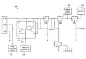
- FIG. 2is a schematic of an embodiment of a power management circuit used with the information handling system of FIG. 1 .
- FIG. 3is a flow chart of an embodiment of a method for managing power.
- FIG. 4is a flow chart of an embodiment of a method for providing a desktop battery storage option in the method of managing power of FIG. 3 .
- FIG. 5is a flow chart of an embodiment of a method for providing a partially mobile battery storage option in the method of managing power of FIG. 3 .
- an IHSmay include any instrumentality or aggregate of instrumentalities operable to compute, classify, process, transmit, receive, retrieve, originate, switch, store, display, manifest, detect, record, reproduce, handle, or utilize any form of information, intelligence, or data for business, scientific, control, entertainment, or other purposes.
- an IHSmay be a personal computer, a PDA, a consumer electronic device, a display device or monitor, a network server or storage device, a switch router or other network communication device, or any other suitable device and may vary in size, shape, performance, functionality, and price.
- the IHSmay include memory, one or more processing resources such as a central processing unit (CPU) or hardware or software control logic.
- CPUcentral processing unit
- Additional components of the IHSmay include one or more storage devices, one or more communications ports for communicating with external devices as well as various input and output (I/O) devices, such as a keyboard, a mouse, and a video display.
- the IHSmay also include one or more buses operable to transmit communications between the various hardware components.
- IHS 100includes a processor 102 , which is connected to a bus 104 .
- Bus 104serves as a connection between processor 102 and other components of IHS 100 .
- An input device 106is coupled to processor 102 to provide input to processor 102 .
- Examples of input devicesmay include keyboards, touchscreens, pointing devices such as mouses, trackballs, and trackpads, and/or a variety of other input devices known in the art.
- Programs and dataare stored on a mass storage device 108 , which is coupled to processor 102 . Examples of mass storage devices may include hard discs, optical disks, magneto-optical discs, solid-state storage devices, and/or a variety other mass storage devices known in the art.
- IHS 100further includes a display 110 , which is coupled to processor 102 by a video controller 112 .
- a system memory 114is coupled to processor 102 to provide the processor with fast storage to facilitate execution of computer programs by processor 102 .
- Examples of system memorymay include random access memory (RAM) devices such as dynamic RAM (DRAM), synchronous DRAM (SDRAM), solid state memory devices, and/or a variety of other memory devices known in the art. It should be understood that other buses and intermediate circuits can be deployed between the components described above and processor 102 to facilitate interconnection between the components and the processor 102 .
- a power supply system 116is coupled to some or all of the components of the IHS 100 in order to provide power to those components.
- the power supply system 116includes a power management system 118 that is coupled to a battery 120 .
- the battery 120may include a battery pack made up of a plurality of batteries.
- the battery 120may include a variety of electrochemical batteries known in the art. However, one of skill in the art will recognize that other battery technologies may be used without departing from the scope of the present disclosure.
- An adapter 122 that is coupled to an external power source 124is coupled to the power management system 118 through an external power source coupling 126 .
- the adapter 122may be an AC/DC adapter known in the art that is operable to convert an alternating current (AC) from the external power source 124 to a direct current (DC).
- ACalternating current
- DCdirect current
- the power supply system 116may include other components such as, for example, a battery management unit (BMU) that is coupled to the battery 120 .
- a chassis 128houses some or all of the components of IHS 100 and the power supply system 116 .
- the illustrated embodimentmay be appropriate for a portable IHS, with the chassis 128 housing the IHS components and the power supply system 116 , and including the external power source coupling 126 on a chassis surface such that the adapter 122 may be coupled to the external power source coupling 126 to couple the external power source 124 to the power management system 118 .
- the adapter 122may be coupled to the external power source coupling 126 to couple the external power source 124 to the power management system 118 .
- other configurationsmay be used without departing from the scope of the present disclosure.
- the power management circuit 200may be included on a circuit board that is housed by the chassis 128 , described above with reference to FIG. 1 , and may be coupled to or included in the power management system 118 .
- the power management circuit 200includes a power supply detection and identification circuit 202 that is coupled to an external power source 204 and a battery 206 , which may be the external power source 124 and the battery 120 described above with reference to FIG. 1 .
- a controller 208is coupled to the power supply detection and identification circuit 202 , the external power source 204 , and the battery 206 through a power source control circuit 210 .
- the power management circuit 200may also include metal oxide semiconductor field effect transistors (MOSFETs), resistors, capacitors, and a variety of other components known in the art, as illustrated in FIG. 2 .
- MOSFETsmetal oxide semiconductor field effect transistors
- resistorsresistors
- capacitorscapacitors
- power management circuit 200may be modified from the embodiment illustrated in FIG. 2 without departing from the scope of the present disclosure.
- the method 300begins by determining a battery storage option.
- the method 300may begin at decision block 302 where it is determined whether a battery power level in the battery 120 has exceeded a first predetermined level for a predetermined time.
- the battery power levelmay be the relative state of charge (RSOC) of the battery.
- RSOCrelative state of charge
- the RSOC of a batteryis a close approximation of the remaining capacity of the battery and may depend on a number of battery factors such as the age, the number of charge/discharge cycles, the voltage level, the current consumption, the temperature, and/or other factors known in the art.
- the controller 208may be programmed to determine whether the battery power level in the battery 120 has exceeded the first predetermined level for the predetermined time.
- the controller 208may determine whether the RSOC of the battery 120 has exceeded 93% (i.e., the first predetermined level) for over 3 days (i.e., the predetermined time.) If the battery power level in the battery 120 has not exceeded the first predetermined level for the predetermined time, the method 300 returns to decision block 302 to continue to check the battery power level in the battery 120 to determine if it has exceeded the first predetermined level for the predetermined time.
- the method 300determines that the battery power level in the battery 120 has exceeded the first predetermined level for the predetermined time.
- the method 300proceeds to block 304 where a user is prompted to select a battery storage option.
- the usermay be presented with a plurality of battery storage options, which will be explained in further detail below, that may include, for example, a desktop battery storage option for portable IHSs that are predominantly connected to an external power source, a partially mobile battery storage option for portable IHSs that typically use battery power for only relatively short periods of time, and a fully mobile storage option for portable IHSs that regularly use battery power for relatively significant periods of time.
- the usermay be presented the battery storage options, for example, through a graphical user interface (GUI) on the display 110 of the IHS 100 .
- GUIgraphical user interface
- the controller 208may be programmed to help present the battery storage options to the user (e.g., codes and for the desktop battery storage option, the partially mobile battery storage option, and/or the fully mobile battery storage option may be included in the controller 208 to be sent to the BMU or other components of the system.)
- the battery storage optionsmay be presented to the user as a ‘pop-up’ window on the IHS 100 upon the method 300 determining in decision block 302 that the battery power level in the battery 120 has exceeded the first predetermined level for the predetermined time.
- decision block 302may be skipped, and the user of the IHS 100 may access controls in the IHS 100 to select the battery storage option.
- the method 300may automatically select the battery storage option (e.g., desktop battery storage option, the partially mobile battery storage option, or the fully mobile battery storage option) upon the battery power level in the battery 120 exceeding a specific predetermined level for a predetermined time, as will be described in further detail below. While only three battery storage options will be described, one of skill in the art will recognize that any number of battery storage options may be provided without departing from the scope of the present disclosure.
- the method 300then proceeds to decision block 306 , where the method 300 determines whether the user selected the desktop battery storage option. If, at decision block 306 , the method 300 determines that the user selected the desktop battery storage option, the method 300 proceeds to a method 400 , illustrated in FIG. 4 . In another embodiment, the method 300 may automatically proceed to the method 400 upon the battery power level in the battery 120 exceeding a predetermined level for a predetermined time.
- the method 400begins at decision block 402 where the method 400 determines whether a battery power level in the battery 120 is greater than a second predetermined level.
- the controller 208may be programmed to determine whether the battery power level in the battery 120 is greater than the second predetermined level. For example, at decision block 402 , the controller 208 may determine whether the RSOC of the battery 120 is greater than 50% (i.e., the second predetermined level).
- the method 400determines whether the battery power level in the battery 120 is greater than the second predetermined level. If, at decision block 402 , the method 400 determines that the battery power level in the battery 120 is greater than the second predetermined level, the method 400 proceeds to decision block 404 where the method 400 determines whether the battery 120 is coupled to the power management system 118 .
- the power supply detection and identification circuit 202is operable to detect whether the battery 102 is coupled to the power management system 118 . If, at decision block 404 , the method 400 determines that the battery 120 is not coupled to the power management system 118 , the method 400 proceeds to block 410 where the external power source 124 is enabled to supply power to the IHS 100 .
- the method 400may disable the external power source 124 from supplying power to the IHS 100 during the method 400 , and the combination of decision block 404 and block 410 of the method 400 enable the external power source 124 to supply power through the power supply system 116 to the IHS 100 in the event the battery 120 is removed from the power supply system 116 during the method 400 .
- the power source control circuit 210is operable to enable a DC power path from the external power source 124 and/or the adapter 122 such that power may be supplied to the IHS 100 from the external power source 124 .
- a MOSFET in the power management circuit 200may be turned on by the power source control circuit 210 in order to provide a DC power path between the IHS 100 and the external power source 124 and/or the adapter 122 .
- charge voltage and currentis read from the Electronically Erasable Programmable Read Only Memory (EEPROM) of the BMU. If, at decision block 404 , the method 400 determines that the battery 120 is present in the power supply system 116 , the method 400 proceeds to block 406 where the external power source 124 is disabled from supplying power to the IHS 100 .
- EEPROMElectronically Erasable Programmable Read Only Memory
- the power source control circuit 210is operable to disable a DC power path from the external power source 124 and/or the adapter 122 such that power may not be supplied to the IHS 100 from the external power source 124 , and power is then supplied to the IHS 100 from the battery 120 .
- a MOSFET in the power management circuit 200may be turned off by the power source control circuit 210 to remove a DC power path between the IHS 100 and the external power source 124 and/or the adapter 122 .
- the method 400then proceeds to decision block 408 where the method 400 determines whether the external power source 124 is coupled to the power management system 118 .
- the power supply detection and identification circuit 202is operable to detect whether the external power source 124 is coupled to the power management system 118 . If, at decision block 408 , the method 400 determines that the external power source 124 is not coupled to the power management system 118 (e.g., the external power source 124 and/or adapter 122 have been decoupled from the external power source coupling 126 on the IHS 100 ), the method 400 proceeds to block 410 where the external power source 124 is enabled to supply power to the IHS 100 .
- the external power source control circuit 210is operable to enable a DC power path (e.g., a DC power path between the external power source coupling 126 and one or more components of the IHS 100 ) such that, when the external power source 124 and/or the adapter 122 are recoupled to the external power source coupling 126 , power may be supplied to the IHS 100 from the external power source 124 (i.e., the external power source 124 is enabled to supply power to the IHS 100 .)
- a MOSFET in the power management circuit 200may be turned on by the power source control circuit 210 in order to provide a DC power path to the external power source 124 and/or the adapter 122 .
- charge voltage and currentis read from the Electronically Erasable Programmable Read Only Memory (EEPROM) of the BMU.
- the method 400then proceeds to block 412 where the method 400 sets a charge to a normal charge level.
- the power management system 118is operable to charge the battery 120 using a normal charge level which may be, for example, a normal charge current or a normal charge voltage.
- a normal charge levelmay be a normal charge current that is used to charge the battery 120 when the battery storage option is the fully mobile battery storage option.
- a normal charge currentis the typical charge current provided to charge conventional batteries in portable information handling systems, and may differ depending on the portable information handling system and the battery used.
- a normal charge currentmay range between 2 and 3.6 amps.
- the normal charge currentmay vary without departing from the scope of the present disclosure, and the term ‘normal charge level’ is meant to be relative to a ‘reduced charge level’ that is provided in the method 400 to help extend the life of the battery 120 , as will be described in further detail below.
- the method 400may disable the external power source 124 from supplying power to the IHS 100 and reduce the charge provided to the battery 120 to a reduced charge level during the method 400 , and the combination of decision block 408 and blocks 410 and 412 of the method 400 enable power to be supplied from the external power source 124 through the power supply system 116 to the IHS 100 , and enable the charge provided to the battery 120 to be returned to a normal charge level in the event the external power source 124 and/or the adapter 122 are decoupled from the power management system 118 during the method 400 .
- the decoupling of the external power source 124 from the power management system 118 during the method 400returns the battery storage option from the desktop battery storage option to the fully mobile battery storage option.
- decision block 408the method 400 determines that the external power source 124 is coupled to the power management system 118 , the method 400 returns to decision block 402 to determine whether the battery power level in the battery 120 is greater than the second predetermined level.
- decision blocks 402 and 408 and blocks 404 and 406result in power being supplied from the battery 120 to the IHS 100 as long as the battery power level in the battery 120 is above the second predetermined level, the battery is coupled to the power management system 118 , and the external power source 124 is coupled to the power management system 118 .
- the method 400will draw power from the battery 120 until the battery power level is below the second predetermined level.
- the method 400determines that the battery power level in the battery 120 is not greater than the second predetermined level, the method 400 proceeds to block 414 where the external power source 124 is enabled to supply power to the IHS 100 .
- the external power source control circuit 210is operable to enable the external power source 124 to supply power to the IHS 100 . For example, if power is being supplied by the battery 120 to the IHS 100 , at block 414 of the method 400 the power source control circuit 210 may enable a DC power path between the external power source 124 and the IHS 100 such that the external power source 124 provides power to the IHS 100 and the battery 120 no longer provides power to the IHS 100 .
- a MOSFET in the power management circuit 200may be turned on by the power source control circuit 210 in order to provide a DC power path to the external power source 124 and/or the adapter 122 .
- the method 400then proceeds to block 416 where the method 400 sets a charge for the battery 120 to a reduced charge level.
- the power management system 118is operable to charge the battery 120 using a reduced charge level which is less than a normal charge level that may include a normal charge current or a normal charge voltage, described above.
- a normal charge levelmay be a normal charge current that is used to charge the battery 120 when the battery storage option is the fully mobile battery storage option
- the reduced charge levelmay be a reduced charge current that is less than the normal charge current.
- a normal charge currentis the typical charge current provided to charge conventional batteries in portable information handling systems, and may differ depending on the portable information handling system and the battery involved.
- a normal charge currentmay range between 2 and 3.6 amps.
- the normal charge currentmay vary without departing from the scope of the present disclosure, and the term ‘normal charge level’ is meant to be relative to the reduced charge level that the charge is set at in block 416 of the method 400 .
- the reduced charge currentmay be approximately 64 milliamps.
- the method 400then proceeds to decision block 418 where the method 400 determines whether the external power source 124 is coupled to the power management system 118 .
- the power supply detection and identification circuit 202is operable to detect whether the external power source 124 is coupled to the power management system 118 .
- the method 400determines that the external power source 124 is not coupled to the power management system 118 (e.g., the external power source 124 and/or adapter 122 have been decoupled from the external power source coupling 126 on the IHS 100 ), the method 400 proceeds to blocks 410 and 412 where the external power source 124 is enabled to supply power to the IHS 100 and the method 400 sets a charge for the battery 120 to a normal charge level, as described above.
- the combination of decision block 418 and blocks 410 and 412 of the method 400enable power to be supplied from the external power source 124 through the power supply system 116 to the IHS 100 , and enable the charge provided to the battery 120 to be returned to a normal charge level, in the event the external power source 124 and/or the adapter 122 are decoupled from the power management system 118 during the method 400 .
- the decoupling of the external power source 124 from the power management system 118 during the method 400returns the battery storage option from the desktop battery storage option to the fully mobile battery storage option.
- the method 400determines whether the battery power level in the battery 120 is greater than a third predetermined level.
- the controller 208may be programmed to determine whether the battery power level in the battery 120 is greater than the third predetermined level. For example, at decision block 420 , the controller 208 may determine whether the RSOC of the battery 120 is greater than 75% (i.e., the third predetermined level).
- the method 400determines that the battery power level in the battery 120 is not greater than the third predetermined level, the method 400 returns to decision block 418 to determine whether the external power source 124 is coupled to the power management system 118 . If, at decision block 420 , the method 400 determines that the battery power level in the battery 120 is greater than the third predetermined level, the method 400 returns to decision block 402 to determine whether the battery power level in the battery 120 is greater than the second predetermined level.
- decision blocks 418 and 420result in power being supplied from the external power source 124 to the IHS 100 and the charge being supplied to the battery 120 at the reduced charge level as long as the battery power level in the battery 120 is below the third predetermined level and the external power source 408 is coupled to the power management system 118 .
- the battery 120will be charged at the reduced charge level until the battery power level in the battery 120 is greater than the third predetermined level.
- the method 400provides a desktop battery storage option that will disable power supply to the IHS 100 from the external power source 124 such that power is supplied to the IHS 100 from the battery 120 until the battery power level in the battery 120 is below a second predetermined level (e.g., 50% the RSOC of the battery 120 ).
- a second predetermined levele.g. 50% the RSOC of the battery 120
- the method 400will enable power supply to the IHS 100 from the external power source 124 such that the battery 120 is no longer supplying power to the IHS 100 , and provide the battery 120 with a charge at a reduced charge level (e.g., 64 milliamps) until the battery power level in the battery 120 is above a third predetermined level (e.g., 75% the RSOC of the battery 120 ).
- the method 400will continue discharging the battery 120 and then charging the battery 120 at a reduced charge level between the second predetermined level and the third predetermined level as long as the battery 120 and the external power source 124 are coupled to the power management system 118 .
- the method 400will enable power supply from the external power source 124 to the IHS 100 and reset the charge to be provided to the battery 120 to a normal charge level.
- the method 400will enable power to be supplied from the external power source 124 to the IHS 100 when the external power source 124 is recoupled to the power management system 118 , and reset the charge to be provided to the battery 120 to a normal charge level.
- the method 300determines whether the user selected the partially mobile battery storage option. If, at decision block 308 , the method 300 determines that the user selected the partially mobile battery storage option, the method 300 proceeds to a method 500 , illustrated in FIG. 5 . In another embodiment, the method 300 may automatically proceed to the method 500 upon the battery power level in the battery 120 exceeding a predetermined level for a predetermined time. The method 500 begins at decision block 502 where the method 400 determines whether a battery power level in the battery 120 is greater than a fourth predetermined level.
- the controller 208may be programmed to determine whether the battery power level in the battery 120 is greater than the fourth predetermined level. For example, at decision block 502 , the controller 208 may determine whether the RSOC of the battery 120 is greater than 80% (i.e., the fourth predetermined level).
- the method 500determines whether the battery power level in the battery 120 is greater than the fourth predetermined level. If, at decision block 502 , the method 500 determines that the battery power level in the battery 120 is greater than the fourth predetermined level, the method 500 proceeds to decision block 504 where the method 500 determines whether the battery 120 is coupled to the power management system 118 .
- the power supply detection and identification circuit 202is operable to detect whether the battery 102 is coupled to the power management system 118 . If, at decision block 504 , the method 500 determines that the battery 120 is not coupled to the power management system 118 , the method 500 proceeds to block 510 where the external power source 124 is enabled to supply power to the IHS 100 .
- the method 500may disable the external power source 124 from supplying power to the IHS 100 during the method 500 , and the combination of decision block 504 and block 510 of the method 500 enable the external power source 124 to supply power through the power supply system 116 to the IHS 100 in the event the battery 120 is removed from the power supply system 116 during the method 500 .
- the power source control circuit 210is operable to enable a DC power path from the external power source 124 and/or the adapter 122 such that power may be supplied to the IHS 100 from the external power source 124 .
- a MOSFET in the power management circuit 200may be turned on by the power source control circuit 210 in order to provide a DC power path between the IHS 100 and the external power source 124 and/or the adapter 122 .
- charge voltage and currentis read from the Electronically Erasable Programmable Read Only Memory (EEPROM) of the BMU. If, at decision block 504 , the method 500 determines that the battery 120 is present in the power supply system 116 , the method 500 proceeds to block 506 where the external power source 124 is disabled from supplying power to the IHS 100 .
- EEPROMElectronically Erasable Programmable Read Only Memory
- the power source control circuit 210is operable to disable a DC power path from the external power source 124 and/or the adapter 122 such that power may not be supplied to the IHS 100 from the external power source 124 , and power is then supplied to the IHS 100 from the battery 120 .
- a MOSFET in the power management circuit 200may be turned off by the power source control circuit 210 to remove a DC power path between the IHS 100 and the external power source 124 and/or the adapter 122 .
- the method 500then proceeds to decision block 508 where the method 500 determines whether the external power source 124 is coupled to the power management system 118 .
- the power supply detection and identification circuit 202is operable to detect whether the external power source 124 is coupled to the power management system 118 . If, at decision block 508 , the method 500 determines that the external power source 124 is not coupled to the power management system 118 (e.g., the external power source 124 and/or adapter 122 have been decoupled from the external power source coupling 126 on the IHS 100 ), the method 500 proceeds to block 510 where the external power source 124 is enabled to supply power to the IHS 100 .
- the external power source control circuit 210is operable to enable a DC power path (e.g., a DC power path between the external power source coupling 126 and one or more components of the IHS 100 ) such that, when the external power source 124 and/or the adapter 122 are recoupled to the external power source coupling 126 , power may be supplied to the IHS 100 from the external power source 124 (i.e., the external power source 124 is enabled to supply power to the IHS 100 .)
- a MOSFET in the power management circuit 200may be turned on by the power source control circuit 210 in order to provide a DC power path between the IHS 100 and the external power source 124 and/or the adapter 122 .
- charge voltage and currentis read from the Electronically Erasable Programmable Read Only Memory (EEPROM) of the BMU.
- the method 500then proceeds to block 512 where the method 500 sets a charge to a normal charge level.
- the power management system 118is operable to charge the battery 120 using a normal charge level which may be, for example, a normal charge current or a normal charge voltage.
- a normal charge levelmay be a normal charge current that is used to charge the battery 120 when the battery storage option is the fully mobile battery storage option.
- a normal charge currentis the typical charge current provided to charge conventional batteries in portable information handling systems, and may differ depending on the portable information handling system and the battery used.
- a normal charge currentmay range between 2 and 3.6 amps.
- the normal charge currentmay vary without departing from the scope of the present disclosure, and the term ‘normal charge level’ is meant to be relative to a ‘reduced charge level’ that is provided in the method 500 to help extend the life of the battery 120 , as will be described in further detail below.
- the method 500may disable the external power source 124 from supplying power to the IHS 100 and reduce the charge provided to the battery 120 to a reduced charge level during the method 500 , and the combination of decision block 508 and blocks 510 and 512 of the method 500 enable power to be supplied from the external power source 124 through the power supply system 116 to the IHS 100 , and enable the charge provided to the battery 120 to be returned to a normal charge level in the event the external power source 124 and/or the adapter 122 are decoupled from the power management system 118 during the method 500 .
- the decoupling of the external power source 124 from the power management system 118 during the method 500returns the battery storage option from the partially mobile battery storage option to the fully mobile battery storage option.
- the method 500determines that the external power source 124 is coupled to the power management system 118 , the method 500 returns to decision block 502 to determine whether the battery power level in the battery 120 is greater than the fourth predetermined level.
- decision blocks 502 and 508 and blocks 504 and 506result in the power being supplied from the battery 120 to the IHS 100 as long as the battery power level in the battery 120 is above the fourth predetermined level, the battery is coupled to the power management system 118 , and the external power source 124 is coupled to the power management system 118 .
- the method 500will draw power from the battery 120 until the battery power level is below the fourth predetermined level.
- the method 500determines that the battery power level in the battery 120 is not greater than the fourth predetermined level, the method 500 proceeds to block 514 where the external power source 124 is enabled to supply power to the IHS 100 .
- the external power source control circuit 210is operable to enable the external power source 124 to supply power to the IHS 100 . For example, if power is being supplied by the battery 120 to the IHS 100 , at block 514 of the method 500 the power source control circuit 210 may enable a DC power path between the external power source 124 and the IHS 100 such that the external power source 124 provides power to the IHS 100 and the battery 120 no longer provides power to the IHS 100 .
- a MOSFET in the power management circuit 200may be turned on by the power source control circuit 210 in order to provide a DC power path between the IHS 100 and the external power source 124 and/or the adapter 122 .
- the method 500then proceeds to block 516 where the method 500 sets a charge for the battery 120 to a reduced charge level.
- the power management system 118is operable to charge the battery 120 using a reduced charge level which is less than a normal charge level that may include a normal charge current or a normal charge voltage, described above.
- a normal charge levelmay be a normal charge current that is used to charge the battery 120 when the battery storage option is the fully mobile battery storage option
- the reduced charge levelmay be a reduced charge current that is less than the normal charge current.
- a normal charge currentis the typical charge current provided to charge conventional batteries in portable information handling systems, and may differ depending on the portable information handling system and the battery involved.
- a normal charge currentmay range between 2 and 3.6 amps.
- the normal charge currentmay vary without departing from the scope of the present disclosure, and the term ‘normal charge level’ is meant to be relative to the reduced charge level that the charge is set at in block 416 of the method 500 .
- the reduced charge currentmay be approximately 64 milliamps.
- the method 500then proceeds to decision block 518 where the method 500 determines whether the external power source 124 is coupled to the power management system 118 .
- the power supply detection and identification circuit 202is operable to detect whether the external power source 124 is coupled to the power management system 118 .
- the method 500determines that the external power source 124 is not coupled to the power management system 118 (e.g., the external power source 124 and/or adapter 122 have been decoupled from the external power source coupling 126 on the IHS 100 ), the method 500 proceeds to blocks 510 and 512 where the external power source 124 is enabled to supply power to the IHS 100 and the method 500 sets a charge for the battery 120 to a normal charge level, as described above.
- the combination of decision block 518 and blocks 510 and 512 of the method 500enable power to be supplied from the external power source 124 through the power supply system 116 to the IHS 100 , and enable the charge provided to the battery 120 to be returned to a normal charge level, in the event the external power source 124 and/or the adapter 122 are decoupled from the power management system 118 during the method 500 .
- the decoupling of the external power source 124 from the power management system 118 during the method 500returns the battery storage option from the partially mobile battery storage option to the fully mobile battery storage option.
- the method 500determines whether the battery power level in the battery 120 is greater than a fifth predetermined level.
- the controller 208may be programmed to determine whether the battery power level in the battery 120 is greater than the fifth predetermined level. For example, at decision block 520 , the controller 208 may determine whether the RSOC of the battery 120 is greater than 95% (i.e., the fifth predetermined level).
- the method 500determines that the battery power level in the battery 120 is not greater than the fifth predetermined level, the method 500 returns to decision block 518 to determine whether the external power source 124 is coupled to the power management system 118 . If, at decision block 520 , the method 500 determines that the battery power level in the battery 120 is greater than the fifth predetermined level, the method 500 returns to decision block 502 to determine whether the battery power level in the battery 120 is greater than the fourth predetermined level.
- decision blocks 518 and 520result in power being supplied from the external power source 124 to the IHS 100 and the charge being supplied to the battery 120 at the reduced charge level as long as the battery power level in the battery 120 is below the fifth predetermined level and the external power source 408 is coupled to the power management system 118 .
- the battery 120will be charged at the reduced charge level until the battery power level in the battery 120 is greater than the fifth predetermined level.
- the method 500provides a partially mobile battery storage option that will disable power supply to the IHS 100 from the external power source 124 such that power is supplied to the IHS 100 from the battery 120 until the battery power level in the battery 120 is below a fourth predetermined level (e.g., 80% the RSOC of the battery).
- a fourth predetermined levele.g., 80% the RSOC of the battery.
- the method 500will enable power supply to the IHS 100 from the external power source 124 such that the battery 120 is no longer supplying power to the IHS 100 , and provide the battery 120 with a charge at a reduced charge level (e.g., 64 milliamps) until the battery power level in the battery 120 is above a fifth predetermined level (e.g., 95% the RSOC of the battery 120 ).
- the method 500will continue discharging the battery 120 and then charging the battery 120 at a reduced charge level between the fourth predetermined level and the fifth predetermined level as long as the battery 120 and the external power source 124 are coupled to the power management system 118 .
- the method 500will enable power supply from the external power source 124 to the IHS 100 and reset the charge to be provided to the battery 120 to a normal charge level.
- the method 500will enable power to be supplied from the external power source 124 to the IHS 100 when the external power source 124 is recoupled to the power management system 118 , and reset the charge to be provided to the battery 120 to a normal charge level.
- the method 300proceeds to block 310 where the method 300 determines that the user selected a fully mobile battery storage option.
- the fully mobile battery storage optionis a convention battery storage option for a portable IHS in which the battery 120 is continually charged at a normal charge level, described above, and kept at a substantially full battery power level (e.g., 100% the RSOC of the battery 120 ).
- the methods 300 , 400 , or 500may proceed to block 312 of the method 300 , where a timer is reset.
- the timermay be part of or coupled to the controller 208 and may be operable to keep track of the predetermined time for decision block 302 of the method 300 .
- a battery life extending power supply systemthat provides a plurality of battery storage options for extending the life of a battery.
- a batteryis kept at a substantially full battery power level and continually charged at a normal charge level for extended periods of time, while only being discharged occasionally, the cycle life of that battery is reduced relative to batteries that are discharged more regularly.
- the cycle life of such batteries that are only discharged occasionallycan be improved with the battery life extending power supply system described above.
- the battery life extending power supply systemallows users that seldom discharge their batteries to select a desktop or partially mobile battery storage option to extend the life of their battery.
- the desktop battery storage optionwill keep the battery power level of the battery in a predetermined battery power level range (e.g., between 50-75% of the RSOC of the battery) while charging the battery at a reduced charge level (e.g., 64 milliamps).
- the partially mobile battery storage optionwill keep the battery power level of the battery in a predetermined battery power level range (e.g., between 80-95% of the RSOC of the battery) while charging the battery at a reduced charge level (e.g., 64 milliamps).
- a predetermined battery power level rangee.g., between 80-95% of the RSOC of the battery
- Such battery storage optionshave been found to more than double the battery watt-hours for a given battery cycle count, and increase the battery cycle count by over 50% for a given battery watt-hours.
- the battery life extending power supply systemprovides safeguards for transferring power supply between an external power source and the battery so that the system always provides power, while also providing for the automatic resetting of the battery storage
Landscapes
- Engineering & Computer Science (AREA)
- Power Engineering (AREA)
- Theoretical Computer Science (AREA)
- Physics & Mathematics (AREA)
- General Engineering & Computer Science (AREA)
- General Physics & Mathematics (AREA)
- Charge And Discharge Circuits For Batteries Or The Like (AREA)
- Secondary Cells (AREA)
Abstract
Description
Claims (20)
Priority Applications (2)
| Application Number | Priority Date | Filing Date | Title |
|---|---|---|---|
| US12/839,797US8464079B2 (en) | 2010-07-20 | 2010-07-20 | Battery life extending power supply system |
| US13/892,927US8726052B2 (en) | 2010-07-20 | 2013-05-13 | Battery life extending power supply system |
Applications Claiming Priority (1)
| Application Number | Priority Date | Filing Date | Title |
|---|---|---|---|
| US12/839,797US8464079B2 (en) | 2010-07-20 | 2010-07-20 | Battery life extending power supply system |
Related Child Applications (1)
| Application Number | Title | Priority Date | Filing Date |
|---|---|---|---|
| US13/892,927ContinuationUS8726052B2 (en) | 2010-07-20 | 2013-05-13 | Battery life extending power supply system |
Publications (2)
| Publication Number | Publication Date |
|---|---|
| US20120023339A1 US20120023339A1 (en) | 2012-01-26 |
| US8464079B2true US8464079B2 (en) | 2013-06-11 |
Family
ID=45494522
Family Applications (2)
| Application Number | Title | Priority Date | Filing Date |
|---|---|---|---|
| US12/839,797Active2031-06-30US8464079B2 (en) | 2010-07-20 | 2010-07-20 | Battery life extending power supply system |
| US13/892,927ActiveUS8726052B2 (en) | 2010-07-20 | 2013-05-13 | Battery life extending power supply system |
Family Applications After (1)
| Application Number | Title | Priority Date | Filing Date |
|---|---|---|---|
| US13/892,927ActiveUS8726052B2 (en) | 2010-07-20 | 2013-05-13 | Battery life extending power supply system |
Country Status (1)
| Country | Link |
|---|---|
| US (2) | US8464079B2 (en) |
Cited By (11)
| Publication number | Priority date | Publication date | Assignee | Title |
|---|---|---|---|---|
| US20130132747A1 (en)* | 2011-11-21 | 2013-05-23 | Canon Kabushiki Kaisha | Information processing apparatus with power control unit, control method therefor, and storage medium storing control program therefor |
| US20130232348A1 (en)* | 2012-03-02 | 2013-09-05 | Van Winston Oler | Multi-Stage Power Adapter |
| US20130339757A1 (en)* | 2012-06-13 | 2013-12-19 | Karunakar P. Reddy | Systems and methods for providing supplemental power to battery powered information handling systems |
| US20140111014A1 (en)* | 2012-10-23 | 2014-04-24 | Hon Hai Precision Industry Co., Ltd. | Charging and discharging system and method for battery |
| US9098117B2 (en) | 2012-03-02 | 2015-08-04 | Microsoft Technology Licensing, Llc | Classifying the intent of user input |
| US9268373B2 (en) | 2012-03-02 | 2016-02-23 | Microsoft Technology Licensing, Llc | Flexible hinge spine |
| US9304549B2 (en) | 2013-03-28 | 2016-04-05 | Microsoft Technology Licensing, Llc | Hinge mechanism for rotatable component attachment |
| US9348605B2 (en) | 2012-05-14 | 2016-05-24 | Microsoft Technology Licensing, Llc | System and method for accessory device architecture that passes human interface device (HID) data via intermediate processor |
| US9870066B2 (en) | 2012-03-02 | 2018-01-16 | Microsoft Technology Licensing, Llc | Method of manufacturing an input device |
| US10031556B2 (en) | 2012-06-08 | 2018-07-24 | Microsoft Technology Licensing, Llc | User experience adaptation |
| US20200052519A1 (en)* | 2018-08-13 | 2020-02-13 | Dell Products L.P. | Information Handling Systems And Improved Battery Charge Control Methods |
Families Citing this family (8)
| Publication number | Priority date | Publication date | Assignee | Title |
|---|---|---|---|---|
| CN102016755B (en)* | 2008-04-23 | 2014-03-05 | 惠普开发有限公司 | Method and system for imposing one or more power states on a display |
| JP5623090B2 (en)* | 2010-01-29 | 2014-11-12 | キヤノン株式会社 | Information processing apparatus, control method for information processing apparatus, and control program |
| US9575527B2 (en)* | 2014-09-16 | 2017-02-21 | Micron Technology, Inc. | Power delivery circuitry |
| TWI547796B (en)* | 2014-11-13 | 2016-09-01 | 鴻海精密工業股份有限公司 | Motherboard supply circuit |
| US9747957B1 (en) | 2016-05-31 | 2017-08-29 | Micron Technology, Inc. | Power delivery circuitry |
| CN111525650B (en)* | 2020-05-27 | 2025-07-25 | 浙江德施曼科技智能股份有限公司 | Intelligent lock, battery management system and method |
| US11340684B2 (en) | 2020-06-05 | 2022-05-24 | Dell Products L.P. | System and method for predictive battery power management |
| US20230093974A1 (en)* | 2021-09-24 | 2023-03-30 | Intel Corporation | Power supply modes for computing systems |
Citations (7)
| Publication number | Priority date | Publication date | Assignee | Title |
|---|---|---|---|---|
| US5982146A (en)* | 1998-05-15 | 1999-11-09 | Intel Corporation | Method and apparatus for conditioning battery while external power is applied |
| US6657415B2 (en)* | 2001-01-19 | 2003-12-02 | Fujitsu Limited | Portable apparatus |
| US6895516B2 (en)* | 2000-08-16 | 2005-05-17 | International Business Machines Corporation | Switching between source power supply and battery of a system based upon connection status of source power supply and battery and a system parameter indicative of the status of the system |
| US7282891B2 (en)* | 2002-12-30 | 2007-10-16 | Motorola, Inc. | Method for charging a battery |
| US20080116854A1 (en)* | 2006-11-20 | 2008-05-22 | Samsung Electronics Co., Ltd. | Current control in rechargeable electronic devices |
| US7612536B2 (en)* | 2005-10-17 | 2009-11-03 | Hewlett-Packard Development Company, L.P. | Pre-set discharging of batteries |
| US8030890B2 (en)* | 2008-02-15 | 2011-10-04 | Sony Ericsson Mobile Communications Ab | Automatic disconnect of an AC source from a converter |
Family Cites Families (1)
| Publication number | Priority date | Publication date | Assignee | Title |
|---|---|---|---|---|
| US9300015B2 (en) | 2010-05-04 | 2016-03-29 | Dell Products Lp | Systems and methods for monitoring and characterizing information handling system use behavior |
- 2010
- 2010-07-20USUS12/839,797patent/US8464079B2/enactiveActive
- 2013
- 2013-05-13USUS13/892,927patent/US8726052B2/enactiveActive
Patent Citations (7)
| Publication number | Priority date | Publication date | Assignee | Title |
|---|---|---|---|---|
| US5982146A (en)* | 1998-05-15 | 1999-11-09 | Intel Corporation | Method and apparatus for conditioning battery while external power is applied |
| US6895516B2 (en)* | 2000-08-16 | 2005-05-17 | International Business Machines Corporation | Switching between source power supply and battery of a system based upon connection status of source power supply and battery and a system parameter indicative of the status of the system |
| US6657415B2 (en)* | 2001-01-19 | 2003-12-02 | Fujitsu Limited | Portable apparatus |
| US7282891B2 (en)* | 2002-12-30 | 2007-10-16 | Motorola, Inc. | Method for charging a battery |
| US7612536B2 (en)* | 2005-10-17 | 2009-11-03 | Hewlett-Packard Development Company, L.P. | Pre-set discharging of batteries |
| US20080116854A1 (en)* | 2006-11-20 | 2008-05-22 | Samsung Electronics Co., Ltd. | Current control in rechargeable electronic devices |
| US8030890B2 (en)* | 2008-02-15 | 2011-10-04 | Sony Ericsson Mobile Communications Ab | Automatic disconnect of an AC source from a converter |
Non-Patent Citations (1)
| Title |
|---|
| Chia-Fa Chang, Hua Chung, Ligong Wang and Yung Fa Chueh; "Systems and Methods for Monitoring and Characterizing Information Handling System Use Behavior;" U.S. Appl. No. 12/799,871, filed May 4, 2010, 29 Pages. |
Cited By (40)
| Publication number | Priority date | Publication date | Assignee | Title |
|---|---|---|---|---|
| US9277078B2 (en)* | 2011-11-21 | 2016-03-01 | Canon Kabushiki Kaisha | Information processing apparatus with power control unit, control method therefor, and storage medium storing control program therefor |
| US20130132747A1 (en)* | 2011-11-21 | 2013-05-23 | Canon Kabushiki Kaisha | Information processing apparatus with power control unit, control method therefor, and storage medium storing control program therefor |
| US9852855B2 (en) | 2012-03-02 | 2017-12-26 | Microsoft Technology Licensing, Llc | Pressure sensitive key normalization |
| US20130232348A1 (en)* | 2012-03-02 | 2013-09-05 | Van Winston Oler | Multi-Stage Power Adapter |
| US10963087B2 (en) | 2012-03-02 | 2021-03-30 | Microsoft Technology Licensing, Llc | Pressure sensitive keys |
| US9098117B2 (en) | 2012-03-02 | 2015-08-04 | Microsoft Technology Licensing, Llc | Classifying the intent of user input |
| US9116550B2 (en) | 2012-03-02 | 2015-08-25 | Microsoft Technology Licensing, Llc | Device kickstand |
| US9134808B2 (en) | 2012-03-02 | 2015-09-15 | Microsoft Technology Licensing, Llc | Device kickstand |
| US9134807B2 (en) | 2012-03-02 | 2015-09-15 | Microsoft Technology Licensing, Llc | Pressure sensitive key normalization |
| US9146620B2 (en) | 2012-03-02 | 2015-09-29 | Microsoft Technology Licensing, Llc | Input device assembly |
| US9158383B2 (en) | 2012-03-02 | 2015-10-13 | Microsoft Technology Licensing, Llc | Force concentrator |
| US9411751B2 (en) | 2012-03-02 | 2016-08-09 | Microsoft Technology Licensing, Llc | Key formation |
| US9176900B2 (en) | 2012-03-02 | 2015-11-03 | Microsoft Technology Licensing, Llc | Flexible hinge and removable attachment |
| US9176901B2 (en) | 2012-03-02 | 2015-11-03 | Microsoft Technology Licensing, Llc | Flux fountain |
| US9268373B2 (en) | 2012-03-02 | 2016-02-23 | Microsoft Technology Licensing, Llc | Flexible hinge spine |
| US10013030B2 (en) | 2012-03-02 | 2018-07-03 | Microsoft Technology Licensing, Llc | Multiple position input device cover |
| US9275809B2 (en) | 2012-03-02 | 2016-03-01 | Microsoft Technology Licensing, Llc | Device camera angle |
| US9298236B2 (en)* | 2012-03-02 | 2016-03-29 | Microsoft Technology Licensing, Llc | Multi-stage power adapter configured to provide a first power level upon initial connection of the power adapter to the host device and a second power level thereafter upon notification from the host device to the power adapter |
| US9304948B2 (en) | 2012-03-02 | 2016-04-05 | Microsoft Technology Licensing, Llc | Sensing user input at display area edge |
| US9304949B2 (en) | 2012-03-02 | 2016-04-05 | Microsoft Technology Licensing, Llc | Sensing user input at display area edge |
| US9946307B2 (en) | 2012-03-02 | 2018-04-17 | Microsoft Technology Licensing, Llc | Classifying the intent of user input |
| US9904327B2 (en) | 2012-03-02 | 2018-02-27 | Microsoft Technology Licensing, Llc | Flexible hinge and removable attachment |
| US9158384B2 (en) | 2012-03-02 | 2015-10-13 | Microsoft Technology Licensing, Llc | Flexible hinge protrusion attachment |
| US9460029B2 (en) | 2012-03-02 | 2016-10-04 | Microsoft Technology Licensing, Llc | Pressure sensitive keys |
| US9465412B2 (en) | 2012-03-02 | 2016-10-11 | Microsoft Technology Licensing, Llc | Input device layers and nesting |
| US9618977B2 (en) | 2012-03-02 | 2017-04-11 | Microsoft Technology Licensing, Llc | Input device securing techniques |
| US9619071B2 (en) | 2012-03-02 | 2017-04-11 | Microsoft Technology Licensing, Llc | Computing device and an apparatus having sensors configured for measuring spatial information indicative of a position of the computing devices |
| US9678542B2 (en) | 2012-03-02 | 2017-06-13 | Microsoft Technology Licensing, Llc | Multiple position input device cover |
| US9710093B2 (en) | 2012-03-02 | 2017-07-18 | Microsoft Technology Licensing, Llc | Pressure sensitive key normalization |
| US9766663B2 (en) | 2012-03-02 | 2017-09-19 | Microsoft Technology Licensing, Llc | Hinge for component attachment |
| US9870066B2 (en) | 2012-03-02 | 2018-01-16 | Microsoft Technology Licensing, Llc | Method of manufacturing an input device |
| US9348605B2 (en) | 2012-05-14 | 2016-05-24 | Microsoft Technology Licensing, Llc | System and method for accessory device architecture that passes human interface device (HID) data via intermediate processor |
| US9959241B2 (en) | 2012-05-14 | 2018-05-01 | Microsoft Technology Licensing, Llc | System and method for accessory device architecture that passes via intermediate processor a descriptor when processing in a low power state |
| US10031556B2 (en) | 2012-06-08 | 2018-07-24 | Microsoft Technology Licensing, Llc | User experience adaptation |
| US20130339757A1 (en)* | 2012-06-13 | 2013-12-19 | Karunakar P. Reddy | Systems and methods for providing supplemental power to battery powered information handling systems |
| US8793518B2 (en)* | 2012-06-13 | 2014-07-29 | Dell Products Lp | Systems and methods for providing supplemental power to battery powered information handling systems |
| US20140111014A1 (en)* | 2012-10-23 | 2014-04-24 | Hon Hai Precision Industry Co., Ltd. | Charging and discharging system and method for battery |
| US9304549B2 (en) | 2013-03-28 | 2016-04-05 | Microsoft Technology Licensing, Llc | Hinge mechanism for rotatable component attachment |
| US20200052519A1 (en)* | 2018-08-13 | 2020-02-13 | Dell Products L.P. | Information Handling Systems And Improved Battery Charge Control Methods |
| US11909243B2 (en)* | 2018-08-13 | 2024-02-20 | Dell Products L.P. | Information handling systems and improved battery charge control methods |
Also Published As
| Publication number | Publication date |
|---|---|
| US20120023339A1 (en) | 2012-01-26 |
| US20130254564A1 (en) | 2013-09-26 |
| US8726052B2 (en) | 2014-05-13 |
Similar Documents
| Publication | Publication Date | Title |
|---|---|---|
| US8464079B2 (en) | Battery life extending power supply system | |
| US20070279004A1 (en) | Portable charging system | |
| US10693197B2 (en) | System and method of cell block voltage analytics to improve balancing effectiveness and identify self-discharge rate | |
| US7595609B2 (en) | Battery system power path configuration and methods for implementing same | |
| US9753094B2 (en) | Battery performance under high temperature exposure | |
| US8154255B2 (en) | Systems and methods for waking up a battery system | |
| US7436149B2 (en) | Systems and methods for interfacing a battery-powered information handling system with a battery pack of a physically separable battery-powered input or input/output device | |
| US7202631B2 (en) | Battery and system power selector integration scheme | |
| US20070247107A1 (en) | Trickle charging and pre-charging hybrid cells smart battery | |
| US20150067362A1 (en) | Adaptive Integral Battery Pack and Voltage Regulator | |
| US9007025B2 (en) | Systems and methods for configuring and charging hybrid battery systems | |
| US11909243B2 (en) | Information handling systems and improved battery charge control methods | |
| US10491014B2 (en) | Battery management system and method for extending time until a battery reaches an over-discharged state during storage of an information handling system | |
| US9037877B2 (en) | System and method for operating a plurality of components according to first or second operating characteristics in response to a detected first or second power input characteristic associated with a first or second power input respectively | |
| US20060181244A1 (en) | Systems and methods for integration of charger regulation within a battery system | |
| US20100097118A1 (en) | Activating an Information Handling System Battery From a Ship Mode | |
| TWI578661B (en) | Power supply apparatus, method and system | |
| US11073885B2 (en) | Battery architecture for variable loads and output topologies in an information handling system | |
| US20070106913A1 (en) | Implementing power over network data link for systems utilizing multiple power sources | |
| US7589497B2 (en) | Field expandable battery systems and related methods | |
| US8022671B2 (en) | Battery under-voltage protection | |
| US20240126358A1 (en) | Low power management for erp6 compliance | |
| US8041468B2 (en) | Method for dynamically cooling when detecting RAID controller with battery present in computer system | |
| US20050242773A1 (en) | Battery pack including multiple battery cell technologies | |
| US11921164B2 (en) | Intelligent battery power discharge management |
Legal Events
| Date | Code | Title | Description |
|---|---|---|---|
| AS | Assignment | Owner name:DELL PRODUCTS L.P., TEXAS Free format text:ASSIGNMENT OF ASSIGNORS INTEREST;ASSIGNORS:CHUEH, YUNG FA;CHANG, CHIA-FA;CHANG, WEN-YUNG;REEL/FRAME:024721/0635 Effective date:20100719 | |
| FEPP | Fee payment procedure | Free format text:PAYOR NUMBER ASSIGNED (ORIGINAL EVENT CODE: ASPN); ENTITY STATUS OF PATENT OWNER: LARGE ENTITY | |
| STCF | Information on status: patent grant | Free format text:PATENTED CASE | |
| AS | Assignment | Owner name:BANK OF AMERICA, N.A., AS ADMINISTRATIVE AGENT, TE Free format text:PATENT SECURITY AGREEMENT (ABL);ASSIGNORS:DELL INC.;APPASSURE SOFTWARE, INC.;ASAP SOFTWARE EXPRESS, INC.;AND OTHERS;REEL/FRAME:031898/0001 Effective date:20131029 Owner name:BANK OF AMERICA, N.A., AS COLLATERAL AGENT, NORTH CAROLINA Free format text:PATENT SECURITY AGREEMENT (TERM LOAN);ASSIGNORS:DELL INC.;APPASSURE SOFTWARE, INC.;ASAP SOFTWARE EXPRESS, INC.;AND OTHERS;REEL/FRAME:031899/0261 Effective date:20131029 Owner name:BANK OF NEW YORK MELLON TRUST COMPANY, N.A., AS FIRST LIEN COLLATERAL AGENT, TEXAS Free format text:PATENT SECURITY AGREEMENT (NOTES);ASSIGNORS:APPASSURE SOFTWARE, INC.;ASAP SOFTWARE EXPRESS, INC.;BOOMI, INC.;AND OTHERS;REEL/FRAME:031897/0348 Effective date:20131029 Owner name:BANK OF AMERICA, N.A., AS ADMINISTRATIVE AGENT, TEXAS Free format text:PATENT SECURITY AGREEMENT (ABL);ASSIGNORS:DELL INC.;APPASSURE SOFTWARE, INC.;ASAP SOFTWARE EXPRESS, INC.;AND OTHERS;REEL/FRAME:031898/0001 Effective date:20131029 Owner name:BANK OF AMERICA, N.A., AS COLLATERAL AGENT, NORTH Free format text:PATENT SECURITY AGREEMENT (TERM LOAN);ASSIGNORS:DELL INC.;APPASSURE SOFTWARE, INC.;ASAP SOFTWARE EXPRESS, INC.;AND OTHERS;REEL/FRAME:031899/0261 Effective date:20131029 Owner name:BANK OF NEW YORK MELLON TRUST COMPANY, N.A., AS FI Free format text:PATENT SECURITY AGREEMENT (NOTES);ASSIGNORS:APPASSURE SOFTWARE, INC.;ASAP SOFTWARE EXPRESS, INC.;BOOMI, INC.;AND OTHERS;REEL/FRAME:031897/0348 Effective date:20131029 | |
| AS | Assignment | Owner name:DELL MARKETING L.P., TEXAS Free format text:RELEASE BY SECURED PARTY;ASSIGNOR:BANK OF AMERICA, N.A., AS ADMINISTRATIVE AGENT;REEL/FRAME:040065/0216 Effective date:20160907 Owner name:COMPELLANT TECHNOLOGIES, INC., MINNESOTA Free format text:RELEASE BY SECURED PARTY;ASSIGNOR:BANK OF AMERICA, N.A., AS ADMINISTRATIVE AGENT;REEL/FRAME:040065/0216 Effective date:20160907 Owner name:DELL INC., TEXAS Free format text:RELEASE BY SECURED PARTY;ASSIGNOR:BANK OF AMERICA, N.A., AS ADMINISTRATIVE AGENT;REEL/FRAME:040065/0216 Effective date:20160907 Owner name:APPASSURE SOFTWARE, INC., VIRGINIA Free format text:RELEASE BY SECURED PARTY;ASSIGNOR:BANK OF AMERICA, N.A., AS ADMINISTRATIVE AGENT;REEL/FRAME:040065/0216 Effective date:20160907 Owner name:PEROT SYSTEMS CORPORATION, TEXAS Free format text:RELEASE BY SECURED PARTY;ASSIGNOR:BANK OF AMERICA, N.A., AS ADMINISTRATIVE AGENT;REEL/FRAME:040065/0216 Effective date:20160907 Owner name:DELL USA L.P., TEXAS Free format text:RELEASE BY SECURED PARTY;ASSIGNOR:BANK OF AMERICA, N.A., AS ADMINISTRATIVE AGENT;REEL/FRAME:040065/0216 Effective date:20160907 Owner name:ASAP SOFTWARE EXPRESS, INC., ILLINOIS Free format text:RELEASE BY SECURED PARTY;ASSIGNOR:BANK OF AMERICA, N.A., AS ADMINISTRATIVE AGENT;REEL/FRAME:040065/0216 Effective date:20160907 Owner name:DELL PRODUCTS L.P., TEXAS Free format text:RELEASE BY SECURED PARTY;ASSIGNOR:BANK OF AMERICA, N.A., AS ADMINISTRATIVE AGENT;REEL/FRAME:040065/0216 Effective date:20160907 Owner name:FORCE10 NETWORKS, INC., CALIFORNIA Free format text:RELEASE BY SECURED PARTY;ASSIGNOR:BANK OF AMERICA, N.A., AS ADMINISTRATIVE AGENT;REEL/FRAME:040065/0216 Effective date:20160907 Owner name:DELL SOFTWARE INC., CALIFORNIA Free format text:RELEASE BY SECURED PARTY;ASSIGNOR:BANK OF AMERICA, N.A., AS ADMINISTRATIVE AGENT;REEL/FRAME:040065/0216 Effective date:20160907 Owner name:WYSE TECHNOLOGY L.L.C., CALIFORNIA Free format text:RELEASE BY SECURED PARTY;ASSIGNOR:BANK OF AMERICA, N.A., AS ADMINISTRATIVE AGENT;REEL/FRAME:040065/0216 Effective date:20160907 Owner name:CREDANT TECHNOLOGIES, INC., TEXAS Free format text:RELEASE BY SECURED PARTY;ASSIGNOR:BANK OF AMERICA, N.A., AS ADMINISTRATIVE AGENT;REEL/FRAME:040065/0216 Effective date:20160907 Owner name:SECUREWORKS, INC., GEORGIA Free format text:RELEASE BY SECURED PARTY;ASSIGNOR:BANK OF AMERICA, N.A., AS ADMINISTRATIVE AGENT;REEL/FRAME:040065/0216 Effective date:20160907 | |
| AS | Assignment | Owner name:FORCE10 NETWORKS, INC., CALIFORNIA Free format text:RELEASE BY SECURED PARTY;ASSIGNOR:BANK OF AMERICA, N.A., AS COLLATERAL AGENT;REEL/FRAME:040040/0001 Effective date:20160907 Owner name:CREDANT TECHNOLOGIES, INC., TEXAS Free format text:RELEASE BY SECURED PARTY;ASSIGNOR:BANK OF AMERICA, N.A., AS COLLATERAL AGENT;REEL/FRAME:040040/0001 Effective date:20160907 Owner name:DELL PRODUCTS L.P., TEXAS Free format text:RELEASE BY SECURED PARTY;ASSIGNOR:BANK OF AMERICA, N.A., AS COLLATERAL AGENT;REEL/FRAME:040040/0001 Effective date:20160907 Owner name:COMPELLENT TECHNOLOGIES, INC., MINNESOTA Free format text:RELEASE BY SECURED PARTY;ASSIGNOR:BANK OF AMERICA, N.A., AS COLLATERAL AGENT;REEL/FRAME:040040/0001 Effective date:20160907 Owner name:DELL INC., TEXAS Free format text:RELEASE BY SECURED PARTY;ASSIGNOR:BANK OF AMERICA, N.A., AS COLLATERAL AGENT;REEL/FRAME:040040/0001 Effective date:20160907 Owner name:DELL SOFTWARE INC., CALIFORNIA Free format text:RELEASE BY SECURED PARTY;ASSIGNOR:BANK OF AMERICA, N.A., AS COLLATERAL AGENT;REEL/FRAME:040040/0001 Effective date:20160907 Owner name:PEROT SYSTEMS CORPORATION, TEXAS Free format text:RELEASE BY SECURED PARTY;ASSIGNOR:BANK OF AMERICA, N.A., AS COLLATERAL AGENT;REEL/FRAME:040040/0001 Effective date:20160907 Owner name:SECUREWORKS, INC., GEORGIA Free format text:RELEASE BY SECURED PARTY;ASSIGNOR:BANK OF AMERICA, N.A., AS COLLATERAL AGENT;REEL/FRAME:040040/0001 Effective date:20160907 Owner name:DELL USA L.P., TEXAS Free format text:RELEASE BY SECURED PARTY;ASSIGNOR:BANK OF AMERICA, N.A., AS COLLATERAL AGENT;REEL/FRAME:040040/0001 Effective date:20160907 Owner name:WYSE TECHNOLOGY L.L.C., CALIFORNIA Free format text:RELEASE BY SECURED PARTY;ASSIGNOR:BANK OF AMERICA, N.A., AS COLLATERAL AGENT;REEL/FRAME:040040/0001 Effective date:20160907 Owner name:ASAP SOFTWARE EXPRESS, INC., ILLINOIS Free format text:RELEASE BY SECURED PARTY;ASSIGNOR:BANK OF AMERICA, N.A., AS COLLATERAL AGENT;REEL/FRAME:040040/0001 Effective date:20160907 Owner name:APPASSURE SOFTWARE, INC., VIRGINIA Free format text:RELEASE BY SECURED PARTY;ASSIGNOR:BANK OF AMERICA, N.A., AS COLLATERAL AGENT;REEL/FRAME:040040/0001 Effective date:20160907 Owner name:DELL MARKETING L.P., TEXAS Free format text:RELEASE BY SECURED PARTY;ASSIGNOR:BANK OF AMERICA, N.A., AS COLLATERAL AGENT;REEL/FRAME:040040/0001 Effective date:20160907 Owner name:DELL INC., TEXAS Free format text:RELEASE BY SECURED PARTY;ASSIGNOR:BANK OF NEW YORK MELLON TRUST COMPANY, N.A., AS COLLATERAL AGENT;REEL/FRAME:040065/0618 Effective date:20160907 Owner name:APPASSURE SOFTWARE, INC., VIRGINIA Free format text:RELEASE BY SECURED PARTY;ASSIGNOR:BANK OF NEW YORK MELLON TRUST COMPANY, N.A., AS COLLATERAL AGENT;REEL/FRAME:040065/0618 Effective date:20160907 Owner name:DELL PRODUCTS L.P., TEXAS Free format text:RELEASE BY SECURED PARTY;ASSIGNOR:BANK OF NEW YORK MELLON TRUST COMPANY, N.A., AS COLLATERAL AGENT;REEL/FRAME:040065/0618 Effective date:20160907 Owner name:WYSE TECHNOLOGY L.L.C., CALIFORNIA Free format text:RELEASE BY SECURED PARTY;ASSIGNOR:BANK OF NEW YORK MELLON TRUST COMPANY, N.A., AS COLLATERAL AGENT;REEL/FRAME:040065/0618 Effective date:20160907 Owner name:DELL MARKETING L.P., TEXAS Free format text:RELEASE BY SECURED PARTY;ASSIGNOR:BANK OF NEW YORK MELLON TRUST COMPANY, N.A., AS COLLATERAL AGENT;REEL/FRAME:040065/0618 Effective date:20160907 Owner name:COMPELLENT TECHNOLOGIES, INC., MINNESOTA Free format text:RELEASE BY SECURED PARTY;ASSIGNOR:BANK OF NEW YORK MELLON TRUST COMPANY, N.A., AS COLLATERAL AGENT;REEL/FRAME:040065/0618 Effective date:20160907 Owner name:DELL SOFTWARE INC., CALIFORNIA Free format text:RELEASE BY SECURED PARTY;ASSIGNOR:BANK OF NEW YORK MELLON TRUST COMPANY, N.A., AS COLLATERAL AGENT;REEL/FRAME:040065/0618 Effective date:20160907 Owner name:FORCE10 NETWORKS, INC., CALIFORNIA Free format text:RELEASE BY SECURED PARTY;ASSIGNOR:BANK OF NEW YORK MELLON TRUST COMPANY, N.A., AS COLLATERAL AGENT;REEL/FRAME:040065/0618 Effective date:20160907 Owner name:DELL USA L.P., TEXAS Free format text:RELEASE BY SECURED PARTY;ASSIGNOR:BANK OF NEW YORK MELLON TRUST COMPANY, N.A., AS COLLATERAL AGENT;REEL/FRAME:040065/0618 Effective date:20160907 Owner name:SECUREWORKS, INC., GEORGIA Free format text:RELEASE BY SECURED PARTY;ASSIGNOR:BANK OF NEW YORK MELLON TRUST COMPANY, N.A., AS COLLATERAL AGENT;REEL/FRAME:040065/0618 Effective date:20160907 Owner name:CREDANT TECHNOLOGIES, INC., TEXAS Free format text:RELEASE BY SECURED PARTY;ASSIGNOR:BANK OF NEW YORK MELLON TRUST COMPANY, N.A., AS COLLATERAL AGENT;REEL/FRAME:040065/0618 Effective date:20160907 Owner name:PEROT SYSTEMS CORPORATION, TEXAS Free format text:RELEASE BY SECURED PARTY;ASSIGNOR:BANK OF NEW YORK MELLON TRUST COMPANY, N.A., AS COLLATERAL AGENT;REEL/FRAME:040065/0618 Effective date:20160907 Owner name:ASAP SOFTWARE EXPRESS, INC., ILLINOIS Free format text:RELEASE BY SECURED PARTY;ASSIGNOR:BANK OF NEW YORK MELLON TRUST COMPANY, N.A., AS COLLATERAL AGENT;REEL/FRAME:040065/0618 Effective date:20160907 | |
| AS | Assignment | Owner name:CREDIT SUISSE AG, CAYMAN ISLANDS BRANCH, AS COLLATERAL AGENT, NORTH CAROLINA Free format text:SECURITY AGREEMENT;ASSIGNORS:ASAP SOFTWARE EXPRESS, INC.;AVENTAIL LLC;CREDANT TECHNOLOGIES, INC.;AND OTHERS;REEL/FRAME:040134/0001 Effective date:20160907 Owner name:THE BANK OF NEW YORK MELLON TRUST COMPANY, N.A., AS NOTES COLLATERAL AGENT, TEXAS Free format text:SECURITY AGREEMENT;ASSIGNORS:ASAP SOFTWARE EXPRESS, INC.;AVENTAIL LLC;CREDANT TECHNOLOGIES, INC.;AND OTHERS;REEL/FRAME:040136/0001 Effective date:20160907 Owner name:CREDIT SUISSE AG, CAYMAN ISLANDS BRANCH, AS COLLAT Free format text:SECURITY AGREEMENT;ASSIGNORS:ASAP SOFTWARE EXPRESS, INC.;AVENTAIL LLC;CREDANT TECHNOLOGIES, INC.;AND OTHERS;REEL/FRAME:040134/0001 Effective date:20160907 Owner name:THE BANK OF NEW YORK MELLON TRUST COMPANY, N.A., A Free format text:SECURITY AGREEMENT;ASSIGNORS:ASAP SOFTWARE EXPRESS, INC.;AVENTAIL LLC;CREDANT TECHNOLOGIES, INC.;AND OTHERS;REEL/FRAME:040136/0001 Effective date:20160907 | |
| FPAY | Fee payment | Year of fee payment:4 | |
| AS | Assignment | Owner name:THE BANK OF NEW YORK MELLON TRUST COMPANY, N.A., T Free format text:SECURITY AGREEMENT;ASSIGNORS:CREDANT TECHNOLOGIES, INC.;DELL INTERNATIONAL L.L.C.;DELL MARKETING L.P.;AND OTHERS;REEL/FRAME:049452/0223 Effective date:20190320 Owner name:THE BANK OF NEW YORK MELLON TRUST COMPANY, N.A., TEXAS Free format text:SECURITY AGREEMENT;ASSIGNORS:CREDANT TECHNOLOGIES, INC.;DELL INTERNATIONAL L.L.C.;DELL MARKETING L.P.;AND OTHERS;REEL/FRAME:049452/0223 Effective date:20190320 | |
| AS | Assignment | Owner name:THE BANK OF NEW YORK MELLON TRUST COMPANY, N.A., TEXAS Free format text:SECURITY AGREEMENT;ASSIGNORS:CREDANT TECHNOLOGIES INC.;DELL INTERNATIONAL L.L.C.;DELL MARKETING L.P.;AND OTHERS;REEL/FRAME:053546/0001 Effective date:20200409 | |
| MAFP | Maintenance fee payment | Free format text:PAYMENT OF MAINTENANCE FEE, 8TH YEAR, LARGE ENTITY (ORIGINAL EVENT CODE: M1552); ENTITY STATUS OF PATENT OWNER: LARGE ENTITY Year of fee payment:8 | |
| AS | Assignment | Owner name:WYSE TECHNOLOGY L.L.C., CALIFORNIA Free format text:RELEASE BY SECURED PARTY;ASSIGNOR:CREDIT SUISSE AG, CAYMAN ISLANDS BRANCH;REEL/FRAME:058216/0001 Effective date:20211101 Owner name:SCALEIO LLC, MASSACHUSETTS Free format text:RELEASE BY SECURED PARTY;ASSIGNOR:CREDIT SUISSE AG, CAYMAN ISLANDS BRANCH;REEL/FRAME:058216/0001 Effective date:20211101 Owner name:MOZY, INC., WASHINGTON Free format text:RELEASE BY SECURED PARTY;ASSIGNOR:CREDIT SUISSE AG, CAYMAN ISLANDS BRANCH;REEL/FRAME:058216/0001 Effective date:20211101 Owner name:MAGINATICS LLC, CALIFORNIA Free format text:RELEASE BY SECURED PARTY;ASSIGNOR:CREDIT SUISSE AG, CAYMAN ISLANDS BRANCH;REEL/FRAME:058216/0001 Effective date:20211101 Owner name:FORCE10 NETWORKS, INC., CALIFORNIA Free format text:RELEASE BY SECURED PARTY;ASSIGNOR:CREDIT SUISSE AG, CAYMAN ISLANDS BRANCH;REEL/FRAME:058216/0001 Effective date:20211101 Owner name:EMC IP HOLDING COMPANY LLC, TEXAS Free format text:RELEASE BY SECURED PARTY;ASSIGNOR:CREDIT SUISSE AG, CAYMAN ISLANDS BRANCH;REEL/FRAME:058216/0001 Effective date:20211101 Owner name:EMC CORPORATION, MASSACHUSETTS Free format text:RELEASE BY SECURED PARTY;ASSIGNOR:CREDIT SUISSE AG, CAYMAN ISLANDS BRANCH;REEL/FRAME:058216/0001 Effective date:20211101 Owner name:DELL SYSTEMS CORPORATION, TEXAS Free format text:RELEASE BY SECURED PARTY;ASSIGNOR:CREDIT SUISSE AG, CAYMAN ISLANDS BRANCH;REEL/FRAME:058216/0001 Effective date:20211101 Owner name:DELL SOFTWARE INC., CALIFORNIA Free format text:RELEASE BY SECURED PARTY;ASSIGNOR:CREDIT SUISSE AG, CAYMAN ISLANDS BRANCH;REEL/FRAME:058216/0001 Effective date:20211101 Owner name:DELL PRODUCTS L.P., TEXAS Free format text:RELEASE BY SECURED PARTY;ASSIGNOR:CREDIT SUISSE AG, CAYMAN ISLANDS BRANCH;REEL/FRAME:058216/0001 Effective date:20211101 Owner name:DELL MARKETING L.P., TEXAS Free format text:RELEASE BY SECURED PARTY;ASSIGNOR:CREDIT SUISSE AG, CAYMAN ISLANDS BRANCH;REEL/FRAME:058216/0001 Effective date:20211101 Owner name:DELL INTERNATIONAL, L.L.C., TEXAS Free format text:RELEASE BY SECURED PARTY;ASSIGNOR:CREDIT SUISSE AG, CAYMAN ISLANDS BRANCH;REEL/FRAME:058216/0001 Effective date:20211101 Owner name:DELL USA L.P., TEXAS Free format text:RELEASE BY SECURED PARTY;ASSIGNOR:CREDIT SUISSE AG, CAYMAN ISLANDS BRANCH;REEL/FRAME:058216/0001 Effective date:20211101 Owner name:CREDANT TECHNOLOGIES, INC., TEXAS Free format text:RELEASE BY SECURED PARTY;ASSIGNOR:CREDIT SUISSE AG, CAYMAN ISLANDS BRANCH;REEL/FRAME:058216/0001 Effective date:20211101 Owner name:AVENTAIL LLC, CALIFORNIA Free format text:RELEASE BY SECURED PARTY;ASSIGNOR:CREDIT SUISSE AG, CAYMAN ISLANDS BRANCH;REEL/FRAME:058216/0001 Effective date:20211101 Owner name:ASAP SOFTWARE EXPRESS, INC., ILLINOIS Free format text:RELEASE BY SECURED PARTY;ASSIGNOR:CREDIT SUISSE AG, CAYMAN ISLANDS BRANCH;REEL/FRAME:058216/0001 Effective date:20211101 | |
| AS | Assignment | Owner name:SCALEIO LLC, MASSACHUSETTS Free format text:RELEASE OF SECURITY INTEREST IN PATENTS PREVIOUSLY RECORDED AT REEL/FRAME (040136/0001);ASSIGNOR:THE BANK OF NEW YORK MELLON TRUST COMPANY, N.A., AS NOTES COLLATERAL AGENT;REEL/FRAME:061324/0001 Effective date:20220329 Owner name:EMC IP HOLDING COMPANY LLC (ON BEHALF OF ITSELF AND AS SUCCESSOR-IN-INTEREST TO MOZY, INC.), TEXAS Free format text:RELEASE OF SECURITY INTEREST IN PATENTS PREVIOUSLY RECORDED AT REEL/FRAME (040136/0001);ASSIGNOR:THE BANK OF NEW YORK MELLON TRUST COMPANY, N.A., AS NOTES COLLATERAL AGENT;REEL/FRAME:061324/0001 Effective date:20220329 Owner name:EMC CORPORATION (ON BEHALF OF ITSELF AND AS SUCCESSOR-IN-INTEREST TO MAGINATICS LLC), MASSACHUSETTS Free format text:RELEASE OF SECURITY INTEREST IN PATENTS PREVIOUSLY RECORDED AT REEL/FRAME (040136/0001);ASSIGNOR:THE BANK OF NEW YORK MELLON TRUST COMPANY, N.A., AS NOTES COLLATERAL AGENT;REEL/FRAME:061324/0001 Effective date:20220329 Owner name:DELL MARKETING CORPORATION (SUCCESSOR-IN-INTEREST TO FORCE10 NETWORKS, INC. AND WYSE TECHNOLOGY L.L.C.), TEXAS Free format text:RELEASE OF SECURITY INTEREST IN PATENTS PREVIOUSLY RECORDED AT REEL/FRAME (040136/0001);ASSIGNOR:THE BANK OF NEW YORK MELLON TRUST COMPANY, N.A., AS NOTES COLLATERAL AGENT;REEL/FRAME:061324/0001 Effective date:20220329 Owner name:DELL PRODUCTS L.P., TEXAS Free format text:RELEASE OF SECURITY INTEREST IN PATENTS PREVIOUSLY RECORDED AT REEL/FRAME (040136/0001);ASSIGNOR:THE BANK OF NEW YORK MELLON TRUST COMPANY, N.A., AS NOTES COLLATERAL AGENT;REEL/FRAME:061324/0001 Effective date:20220329 Owner name:DELL INTERNATIONAL L.L.C., TEXAS Free format text:RELEASE OF SECURITY INTEREST IN PATENTS PREVIOUSLY RECORDED AT REEL/FRAME (040136/0001);ASSIGNOR:THE BANK OF NEW YORK MELLON TRUST COMPANY, N.A., AS NOTES COLLATERAL AGENT;REEL/FRAME:061324/0001 Effective date:20220329 Owner name:DELL USA L.P., TEXAS Free format text:RELEASE OF SECURITY INTEREST IN PATENTS PREVIOUSLY RECORDED AT REEL/FRAME (040136/0001);ASSIGNOR:THE BANK OF NEW YORK MELLON TRUST COMPANY, N.A., AS NOTES COLLATERAL AGENT;REEL/FRAME:061324/0001 Effective date:20220329 Owner name:DELL MARKETING L.P. (ON BEHALF OF ITSELF AND AS SUCCESSOR-IN-INTEREST TO CREDANT TECHNOLOGIES, INC.), TEXAS Free format text:RELEASE OF SECURITY INTEREST IN PATENTS PREVIOUSLY RECORDED AT REEL/FRAME (040136/0001);ASSIGNOR:THE BANK OF NEW YORK MELLON TRUST COMPANY, N.A., AS NOTES COLLATERAL AGENT;REEL/FRAME:061324/0001 Effective date:20220329 Owner name:DELL MARKETING CORPORATION (SUCCESSOR-IN-INTEREST TO ASAP SOFTWARE EXPRESS, INC.), TEXAS Free format text:RELEASE OF SECURITY INTEREST IN PATENTS PREVIOUSLY RECORDED AT REEL/FRAME (040136/0001);ASSIGNOR:THE BANK OF NEW YORK MELLON TRUST COMPANY, N.A., AS NOTES COLLATERAL AGENT;REEL/FRAME:061324/0001 Effective date:20220329 | |
| AS | Assignment | Owner name:SCALEIO LLC, MASSACHUSETTS Free format text:RELEASE OF SECURITY INTEREST IN PATENTS PREVIOUSLY RECORDED AT REEL/FRAME (045455/0001);ASSIGNOR:THE BANK OF NEW YORK MELLON TRUST COMPANY, N.A., AS NOTES COLLATERAL AGENT;REEL/FRAME:061753/0001 Effective date:20220329 Owner name:EMC IP HOLDING COMPANY LLC (ON BEHALF OF ITSELF AND AS SUCCESSOR-IN-INTEREST TO MOZY, INC.), TEXAS Free format text:RELEASE OF SECURITY INTEREST IN PATENTS PREVIOUSLY RECORDED AT REEL/FRAME (045455/0001);ASSIGNOR:THE BANK OF NEW YORK MELLON TRUST COMPANY, N.A., AS NOTES COLLATERAL AGENT;REEL/FRAME:061753/0001 Effective date:20220329 Owner name:EMC CORPORATION (ON BEHALF OF ITSELF AND AS SUCCESSOR-IN-INTEREST TO MAGINATICS LLC), MASSACHUSETTS Free format text:RELEASE OF SECURITY INTEREST IN PATENTS PREVIOUSLY RECORDED AT REEL/FRAME (045455/0001);ASSIGNOR:THE BANK OF NEW YORK MELLON TRUST COMPANY, N.A., AS NOTES COLLATERAL AGENT;REEL/FRAME:061753/0001 Effective date:20220329 Owner name:DELL MARKETING CORPORATION (SUCCESSOR-IN-INTEREST TO FORCE10 NETWORKS, INC. AND WYSE TECHNOLOGY L.L.C.), TEXAS Free format text:RELEASE OF SECURITY INTEREST IN PATENTS PREVIOUSLY RECORDED AT REEL/FRAME (045455/0001);ASSIGNOR:THE BANK OF NEW YORK MELLON TRUST COMPANY, N.A., AS NOTES COLLATERAL AGENT;REEL/FRAME:061753/0001 Effective date:20220329 Owner name:DELL PRODUCTS L.P., TEXAS Free format text:RELEASE OF SECURITY INTEREST IN PATENTS PREVIOUSLY RECORDED AT REEL/FRAME (045455/0001);ASSIGNOR:THE BANK OF NEW YORK MELLON TRUST COMPANY, N.A., AS NOTES COLLATERAL AGENT;REEL/FRAME:061753/0001 Effective date:20220329 Owner name:DELL INTERNATIONAL L.L.C., TEXAS Free format text:RELEASE OF SECURITY INTEREST IN PATENTS PREVIOUSLY RECORDED AT REEL/FRAME (045455/0001);ASSIGNOR:THE BANK OF NEW YORK MELLON TRUST COMPANY, N.A., AS NOTES COLLATERAL AGENT;REEL/FRAME:061753/0001 Effective date:20220329 Owner name:DELL USA L.P., TEXAS Free format text:RELEASE OF SECURITY INTEREST IN PATENTS PREVIOUSLY RECORDED AT REEL/FRAME (045455/0001);ASSIGNOR:THE BANK OF NEW YORK MELLON TRUST COMPANY, N.A., AS NOTES COLLATERAL AGENT;REEL/FRAME:061753/0001 Effective date:20220329 Owner name:DELL MARKETING L.P. (ON BEHALF OF ITSELF AND AS SUCCESSOR-IN-INTEREST TO CREDANT TECHNOLOGIES, INC.), TEXAS Free format text:RELEASE OF SECURITY INTEREST IN PATENTS PREVIOUSLY RECORDED AT REEL/FRAME (045455/0001);ASSIGNOR:THE BANK OF NEW YORK MELLON TRUST COMPANY, N.A., AS NOTES COLLATERAL AGENT;REEL/FRAME:061753/0001 Effective date:20220329 Owner name:DELL MARKETING CORPORATION (SUCCESSOR-IN-INTEREST TO ASAP SOFTWARE EXPRESS, INC.), TEXAS Free format text:RELEASE OF SECURITY INTEREST IN PATENTS PREVIOUSLY RECORDED AT REEL/FRAME (045455/0001);ASSIGNOR:THE BANK OF NEW YORK MELLON TRUST COMPANY, N.A., AS NOTES COLLATERAL AGENT;REEL/FRAME:061753/0001 Effective date:20220329 | |
| AS | Assignment | Owner name:DELL MARKETING L.P. (ON BEHALF OF ITSELF AND AS SUCCESSOR-IN-INTEREST TO CREDANT TECHNOLOGIES, INC.), TEXAS Free format text:RELEASE OF SECURITY INTEREST IN PATENTS PREVIOUSLY RECORDED AT REEL/FRAME (053546/0001);ASSIGNOR:THE BANK OF NEW YORK MELLON TRUST COMPANY, N.A., AS NOTES COLLATERAL AGENT;REEL/FRAME:071642/0001 Effective date:20220329 Owner name:DELL INTERNATIONAL L.L.C., TEXAS Free format text:RELEASE OF SECURITY INTEREST IN PATENTS PREVIOUSLY RECORDED AT REEL/FRAME (053546/0001);ASSIGNOR:THE BANK OF NEW YORK MELLON TRUST COMPANY, N.A., AS NOTES COLLATERAL AGENT;REEL/FRAME:071642/0001 Effective date:20220329 Owner name:DELL PRODUCTS L.P., TEXAS Free format text:RELEASE OF SECURITY INTEREST IN PATENTS PREVIOUSLY RECORDED AT REEL/FRAME (053546/0001);ASSIGNOR:THE BANK OF NEW YORK MELLON TRUST COMPANY, N.A., AS NOTES COLLATERAL AGENT;REEL/FRAME:071642/0001 Effective date:20220329 Owner name:DELL USA L.P., TEXAS Free format text:RELEASE OF SECURITY INTEREST IN PATENTS PREVIOUSLY RECORDED AT REEL/FRAME (053546/0001);ASSIGNOR:THE BANK OF NEW YORK MELLON TRUST COMPANY, N.A., AS NOTES COLLATERAL AGENT;REEL/FRAME:071642/0001 Effective date:20220329 Owner name:EMC CORPORATION, MASSACHUSETTS Free format text:RELEASE OF SECURITY INTEREST IN PATENTS PREVIOUSLY RECORDED AT REEL/FRAME (053546/0001);ASSIGNOR:THE BANK OF NEW YORK MELLON TRUST COMPANY, N.A., AS NOTES COLLATERAL AGENT;REEL/FRAME:071642/0001 Effective date:20220329 Owner name:DELL MARKETING CORPORATION (SUCCESSOR-IN-INTEREST TO FORCE10 NETWORKS, INC. AND WYSE TECHNOLOGY L.L.C.), TEXAS Free format text:RELEASE OF SECURITY INTEREST IN PATENTS PREVIOUSLY RECORDED AT REEL/FRAME (053546/0001);ASSIGNOR:THE BANK OF NEW YORK MELLON TRUST COMPANY, N.A., AS NOTES COLLATERAL AGENT;REEL/FRAME:071642/0001 Effective date:20220329 Owner name:EMC IP HOLDING COMPANY LLC, TEXAS Free format text:RELEASE OF SECURITY INTEREST IN PATENTS PREVIOUSLY RECORDED AT REEL/FRAME (053546/0001);ASSIGNOR:THE BANK OF NEW YORK MELLON TRUST COMPANY, N.A., AS NOTES COLLATERAL AGENT;REEL/FRAME:071642/0001 Effective date:20220329 | |
| MAFP | Maintenance fee payment | Free format text:PAYMENT OF MAINTENANCE FEE, 12TH YEAR, LARGE ENTITY (ORIGINAL EVENT CODE: M1553); ENTITY STATUS OF PATENT OWNER: LARGE ENTITY Year of fee payment:12 |