US8463604B2 - Speech encoding utilizing independent manipulation of signal and noise spectrum - Google Patents
Speech encoding utilizing independent manipulation of signal and noise spectrumDownload PDFInfo
- Publication number
- US8463604B2 US8463604B2US12/455,100US45510009AUS8463604B2US 8463604 B2US8463604 B2US 8463604B2US 45510009 AUS45510009 AUS 45510009AUS 8463604 B2US8463604 B2US 8463604B2
- Authority
- US
- United States
- Prior art keywords
- signal
- filter
- noise shaping
- input
- quantization
- Prior art date
- Legal status (The legal status is an assumption and is not a legal conclusion. Google has not performed a legal analysis and makes no representation as to the accuracy of the status listed.)
- Active, expires
Links
Images


Classifications
- G—PHYSICS
- G10—MUSICAL INSTRUMENTS; ACOUSTICS
- G10L—SPEECH ANALYSIS TECHNIQUES OR SPEECH SYNTHESIS; SPEECH RECOGNITION; SPEECH OR VOICE PROCESSING TECHNIQUES; SPEECH OR AUDIO CODING OR DECODING
- G10L19/00—Speech or audio signals analysis-synthesis techniques for redundancy reduction, e.g. in vocoders; Coding or decoding of speech or audio signals, using source filter models or psychoacoustic analysis
- G10L19/04—Speech or audio signals analysis-synthesis techniques for redundancy reduction, e.g. in vocoders; Coding or decoding of speech or audio signals, using source filter models or psychoacoustic analysis using predictive techniques
- G10L19/08—Determination or coding of the excitation function; Determination or coding of the long-term prediction parameters
- G10L19/087—Determination or coding of the excitation function; Determination or coding of the long-term prediction parameters using mixed excitation models, e.g. MELP, MBE, split band LPC or HVXC
- G—PHYSICS
- G10—MUSICAL INSTRUMENTS; ACOUSTICS
- G10L—SPEECH ANALYSIS TECHNIQUES OR SPEECH SYNTHESIS; SPEECH RECOGNITION; SPEECH OR VOICE PROCESSING TECHNIQUES; SPEECH OR AUDIO CODING OR DECODING
- G10L19/00—Speech or audio signals analysis-synthesis techniques for redundancy reduction, e.g. in vocoders; Coding or decoding of speech or audio signals, using source filter models or psychoacoustic analysis
- G10L19/02—Speech or audio signals analysis-synthesis techniques for redundancy reduction, e.g. in vocoders; Coding or decoding of speech or audio signals, using source filter models or psychoacoustic analysis using spectral analysis, e.g. transform vocoders or subband vocoders
- G—PHYSICS
- G10—MUSICAL INSTRUMENTS; ACOUSTICS
- G10L—SPEECH ANALYSIS TECHNIQUES OR SPEECH SYNTHESIS; SPEECH RECOGNITION; SPEECH OR VOICE PROCESSING TECHNIQUES; SPEECH OR AUDIO CODING OR DECODING
- G10L19/00—Speech or audio signals analysis-synthesis techniques for redundancy reduction, e.g. in vocoders; Coding or decoding of speech or audio signals, using source filter models or psychoacoustic analysis
- G10L19/04—Speech or audio signals analysis-synthesis techniques for redundancy reduction, e.g. in vocoders; Coding or decoding of speech or audio signals, using source filter models or psychoacoustic analysis using predictive techniques
- G10L19/06—Determination or coding of the spectral characteristics, e.g. of the short-term prediction coefficients
- G—PHYSICS
- G10—MUSICAL INSTRUMENTS; ACOUSTICS
- G10L—SPEECH ANALYSIS TECHNIQUES OR SPEECH SYNTHESIS; SPEECH RECOGNITION; SPEECH OR VOICE PROCESSING TECHNIQUES; SPEECH OR AUDIO CODING OR DECODING
- G10L19/00—Speech or audio signals analysis-synthesis techniques for redundancy reduction, e.g. in vocoders; Coding or decoding of speech or audio signals, using source filter models or psychoacoustic analysis
- G10L19/04—Speech or audio signals analysis-synthesis techniques for redundancy reduction, e.g. in vocoders; Coding or decoding of speech or audio signals, using source filter models or psychoacoustic analysis using predictive techniques
- G10L19/26—Pre-filtering or post-filtering
Definitions
- the present inventionrelates to the process of quantization in the encoding of speech, e.g. for transmission over a transmission medium such as by means of an electronic signal over a wired connection or electro-magnetic signal over a wireless connection.
- Quantizationis the process of converting a continuous range of values into a set of discrete values; or more realistically in the case of a digital system, converting a larger set of approximately-continuous discrete values into a smaller set of more substantially discrete values.
- the quantized discrete valuesare typically selected from predetermined representation levels.
- Types of quantizationinclude scalar quantization, trellis quantization, lattice quantization, vector quantization, algebraic codebook quantization, and others.
- the quantizationhas the effect that the quantized version of the signal requires fewer bits per unit time, and therefore takes less signalling overhead to transmit or less storage space to store.
- noise shaping quantizermay be used to quantize the signal.
- the idea behind a noise shaping quantizeris to quantize the signal in a manner that weights or biases the noise effect created by the quantization into less noticeable parts of the frequency spectrum, e.g. where the human ear is more tolerant to noise, and/or where the speech energy is high such that the relative effect of the noise is less. That is, noise shaping is a technique to produce a quantized signal with a spectrally shaped coding noise.
- the coding noisemay be defined quantitatively as the difference between input and output signals of the overall quantizing system, i.e. of the whole codec, and this typically has a spectral shape (whereas the quantization error usually refers to the difference between the immediate inputs and outputs of the actual quantization unit, which is typically spectrally flat).
- FIG. 1 ais a schematic block diagram showing one example of a noise shaping quantizer 11 , which receives an input signal x(n) and produces a quantized output signal y(n).
- the noise shaping quantizer 11comprises a quantization unit 13 , a noise shaping filter 15 , an addition stage 17 and a subtraction stage 19 .
- the subtraction stage 19calculates an error signal in the form of the coding noise q(n) by taking the difference between the quantized output signal y(n) and the input to the quantization unit 13 , where n is the sample number.
- the coding noise q(n)is supplied to the noise shaping filter 15 where it is filtered to produce a filtered output.
- the addition stage 17then adds this filtered output to the input signal x(n) and supplies the resulting signal to the input of the quantization unit 13 .
- the input, output and error signalsare represented in FIG. 1 a in the time domain as functions of time x(n), y(n) and q(n) respectively (with time being measured in number of samples n).
- the same signalscan also be represented in the frequency domain as functions of frequency X(z), Y(z) and Q(z) respectively (z representing frequency).
- the quantization error Q(z)typically has a spectrum that is approximately white (i.e. approximately constant energy across its frequency spectrum). Therefore the coding noise has a spectrum approximately proportional to 1+F(z).
- FIG. 1 bAnother example of a noise shaping quantizer 21 is shown schematically in FIG. 1 b .
- the noise shaping quantizer 21comprises a quantization unit 23 , a noise shaping filter 25 , an addition stage 27 and a subtraction stage 29 .
- an error signal in the form of the coding noise q(n)is supplied to the noise shaping filter 25 where it is filtered to produce a filtered output, and the addition stage 27 then adds this filtered output to the input signal x(n) and supplies the resulting signal to the input of the quantization unit 13 .
- the quantized output signal y(n)can be described in the frequency domain as:
- Y ⁇ ( z )X ⁇ ( z ) + Q ⁇ ( z ) 1 - F ⁇ ( z ) .
- the coding noisehas a spectrum proportional to (1 ⁇ F(z)) ⁇ 1 .
- FIG. 1 cis a schematic block diagram of an analysis-by-synthesis quantizer 31 .
- Analysis-by-synthesisis a method in speech coding whereby a quantizer codebook is searched to minimize a weighted coding error signal (the codebook defines the possible representation levels for the quantization). This works by trying representing samples of the input signal according to a plurality of different possible representation levels in the codebook, and selecting the levels which produce the least energy in the weighted coding error signal. The weighting is to bias the coding error towards less noticeable parts of the frequency spectrum.
- the analysis-by-synthesis quantizer 31receives an input signal x(n) and produces a quantized output signal y(n). It comprises a controllable quantization unit 33 , a weighting filter 35 , an energy minimization block 37 , and a subtraction stage 39 .
- the quantization unit 33generates a plurality of possible versions of a portion of the quantized output signal y(n). For each possible version, the subtraction stage 39 subtracts the quantized output y(n) from the input signal x(n) to produce an error signal, which is supplied to the weighting filter 35 .
- the weighting filter 35filters the error signal to produce a weighted error signal, and supplies this filtered output to the energy minimization block 37 .
- the energy minimization block 37determines the energy in the weighted error signal for each possible version of the quantized output signal y(n), and selects the version resulting in the least energy in the weighted error signal.
- the weighted coding error signalis computed by filtering the coding error with a weighting filter 35 , which can be represented in the frequency domain by a function W(z).
- W(z)For a well-constructed codebook able to approximate the input signal, the weighted coding noise signal with minimum energy is approximately white. That means that the coding noise signal itself has a noise spectrum shaped proportional the inverse of the weighting filter: W(z) ⁇ 1 .
- indices corresponding to the representation levels selected to represent the samples of the signalare transmitted to the decoder in the encoded signal, such that the quantized signal y(n) can be reconstructed again from those indices in the decoding.
- the input to the quantizeris commonly whitened with a prediction filter.
- a prediction filtergenerates predicted values of samples in a signal based on previous samples.
- speech codingit is possible to do this because of correlations present in speech samples (correlation being a statistical measure of a degree of relationship between groups of data). These correlations could be “long-term” correlations between quasi-periodic portions of the speech signal, or “short-term” correlations on a timescale shorter than such periods.
- the predicted samplesare then subtracted from the actual samples to produce a residual signal.
- This residual signali.e. the difference between the predicted and actual samples, typically has a lower energy than the original speech samples and therefore requires fewer bits to quantize. That is, it is only necessary to quantize the difference between the original and predicted signals.
- FIG. 1 dshows an example of a noise shaping quantizer 41 where the quantizer input is whitened using linear prediction filter P(z).
- the predictoroperates in closed-loop, meaning that a prediction of the input signal is based on the quantized output signal.
- the output of the prediction filteris subtracted from the quantizer input and added to the quantizer output to form the quantized output signal.
- the noise shaping quantizer 41comprises a quantization unit 42 , a prediction filter 44 , a noise shaping filter 45 , a first addition stage 46 , a second addition stage 47 , a first subtraction stage 48 and a second subtraction stage 49 .
- the first subtraction stage 48calculates the coding error (i.e. coding noise) by taking the difference between the quantized output signal y(n) and the input signal x(n), and supplies the coding noise to the noise shaping filter 45 where it is filtered to generate a filtered output.
- the quantized output signal y(n)is also supplied to the prediction filter 44 where it is filtered to generate another filtered output.
- the output of the noise shaping filter 45is added to the input signal x(n) at the first addition stage 46 and the output of the prediction filter 44 is subtracted from the input signal x(n) at the second subtraction stage 49 .
- the resulting signalis input to the quantization unit 42 , to generate an output being a quantized version of its input, and also to generate quantization indices i(n) corresponding to the representation levels selected to represent that input in the quantization.
- the output of the prediction filter 44is then added back to the output of the quantization unit 42 at the second addition stage 47 to produce the quantized output signal y(n).
- the quantized output signal y(n)is generated only for feedback to the prediction filter 44 and noise shaping filter 45 : it is the quantization indices i(n) that are transmitted to the decoder in the encoded signal.
- the decoderwill then reconstruct the quantized signal y(n) using those indices i(n).
- FIG. 1 eshows another example of a noise shaping quantizer 51 where the quantizer input is whitened using a linear prediction filter P(z).
- the predictoroperates in open-loop manner, meaning that a prediction of the input signal is based on the input signal and a prediction of the output is based on the quantized output signal.
- the output of the input prediction filteris subtracted from the quantizer input and the output of the output prediction filter is added to the quantizer output to form the quantized output signal.
- the noise shaping quantizer 51comprises a quantization unit 52 , a first instance of a prediction filter 54 , a second instance of the same prediction filter 54 ′, a noise shaping filter 55 , a first addition stage 56 , a second addition stage 57 , a first subtraction stage 58 and a second subtraction stage 59 .
- the quantization unit 52 , noise shaping filter 55 , and first addition and subtraction stages 56 and 58are arranged to operate similarly to those of FIG. 1 d . However, in contrast to FIG.
- the output of the first addition stage 54is supplied to the first instance of the prediction filter 54 where it is filtered to generate a filtered output, and this output of the first instance of the prediction filter 54 is then subtracted from the output of the first addition stage 56 at the second subtraction stage 59 before the resulting signal is input to the quantization unit 52 .
- the output of the second instance of the prediction filter 54 ′is added to the output of the quantization unit 52 at the second addition stage 57 to generate the quantized output signal y(n), and this quantized output signal y(n) is supplied to the second instance of the prediction filter 54 ′ to generate its filtered output.
- a method of encoding speechcomprising: receiving an input signal representing a property of speech; quantizing the input signal, thus generating a quantized output signal; prior to said quantization, supplying a version of the input signal to a first noise shaping filter having a first set of filter coefficients, thus generating a first filtered signal based on that version of the input signal and the first set of filter coefficients; following said quantization, supplying a version of the quantized output signal to a second noise shaping filter having a second set of filter coefficients different than said first set, thus generating a second filter signal based on that version of the quantized output signal and the second set of filter coefficients; performing a noise shaping operation to control a frequency spectrum of a noise effect in the quantized output signal caused by said quantization, wherein the noise shaping operation is performed based on both the first and second filtered signals; and transmitting the quantised output signal in an encoded signal.
- the methodmay further comprise updating at least one of the first and second filter coefficients based on a property of the input signal.
- Said propertymay comprise at least one of a signal spectrum and a noise spectrum of the input signal.
- Said updatingmay be performed at regular time intervals.
- the methodmay further comprise multiplying the input signal by an adjustment gain prior to said quantization, in order to compensate for a difference between said input signal and a signal decoded from said quantized signal that would otherwise be caused by the difference between the first and second noise shaping filters.
- Said noise shaping operationmay comprise, prior to said quantization, subtracting the first filtered signal from the input signal and adding the second filtered signal to the input signal.
- the first noise shaping filtermay be an analysis filter and the second noise shaping filter may be a synthesis filter.
- Said noise shaping operationmay comprise generating a plurality of possible quantized output signals and selecting that having least energy in a weighted error relative to the input signal.
- Said noise shaping filtersmay comprise weighting filters of an analysis-by-synthesis quantizer.
- the methodmay comprise subtracting the output of a prediction filter from the input signal prior to said quantization, and adding the output of a prediction filter to the quantized output signal following said quantization.
- an encoder for encoding speechcomprising: an input arranged to receive an input signal representing a property of speech; a quantization unit operatively coupled to said input configured to quantize the input signal, thus generating a quantized output signal; a first noise shaping filter having a first set of filter coefficients and being operatively coupled to said input, arranged to receive a version of the input signal prior to said quantization, and configured to generate a first filtered signal based on that version of the input signal and the first set of filter coefficients; a second noise shaping filter having a second set of filter coefficients different from the first set and being operatively coupled to an output of said quantization unit, arranged to receive a version of the quantized output signal following said quantization, and configured to generate a second filter signal based on that version of the quantized output signal and the second set of filter coefficients; a noise shaping element operatively coupled to the first and second noise shaping filters, and configured to perform a noise shaping operation to control
- a computer program productfor encoding speech, the program comprising code configured so as when executed on a processor to:
- corresponding computer program productssuch as client application products configured so as when executed on a processor to perform the methods described above.
- a communication systemcomprising a plurality of end-user terminals each comprising a corresponding encoder.
- FIG. 1 ais a schematic diagram of a noise shaping quantizer
- FIG. 1 bis a schematic diagram of another noise shaping quantizer
- FIG. 1 cis a schematic diagram of an analysis-by-synthesis quantizer
- FIG. 1 dis a schematic diagram of a noise shaping predictive quantizer
- FIG. 1 eis a schematic diagram of another noise shaping predictive quantizer
- FIG. 2 ais a schematic diagram of another noise shaping predictive quantizer
- FIG. 2 bis a schematic diagram of another noise shaping predictive quantizer
- FIG. 2 cis a schematic diagram of a predictive analysis-by-synthesis quantizer
- FIG. 3illustrates a modification to a signal frequency spectrum
- FIG. 4 ais a schematic representation of a source-filter model of speech
- FIG. 4 bis a schematic representation of a frame
- FIG. 4 cis a schematic representation of a source signal
- FIG. 4 dis a schematic representation of variations in a spectral envelope
- FIG. 5is a schematic diagram of an encoder
- FIG. 6 ais another schematic diagram of a noise shaping predictive quantizer
- FIG. 6 bis another schematic diagram of a noise shaping predictive quantizer
- FIG. 7 ais another schematic diagram of a decoder
- FIG. 7 bshows more detail of the decoder of FIG. 7 a.
- the present inventionapplies one filter to a signal before quantization and another filter with different filter coefficients to a signal after quantization. As will be discussed in more detail below, this advantageously allows a signal spectrum and coding noise spectrum to be manipulated separately, and can be applied in order to improve coding efficiency and/or reduce noise.
- either the filter outputscan be combined to create an input to a quantization unit, or the filter outputs can be subtracted to create a weighted speech signal that is minimized by searching a codebook.
- both filtersare updated over time based on a noise shaping analysis of the input signal.
- the noise shaping analysisdetermines exactly how the signal and coding noise should be shaped over spectrum and time such that the perceived quality of the resulting quantized output signal is maximized.
- the noise shaping predictive quantizer 200comprises a quantization unit 202 , a prediction filter 204 in a closed-loop configuration, a first noise shaping filter 206 having first filter coefficients, and a second noise shaping filter 208 having second filter coefficients different from the first filter coefficients.
- the noise shaping predictive quantizer 200also comprises an amplifier 210 , a first subtraction stage 212 , a first addition stage 214 , a second subtraction stage 216 and a second addition stage 218 .
- the first noise shaping filter 206 and the first subtraction stage 212each have inputs arranged to receive an input signal x(n) representing speech or some property of speech.
- the other input of the first subtraction stage 212is coupled to the output of the first noise shaping filter 206 , and the output of the first subtraction stage 212 is coupled to the input of the amplifier 210 .
- the output of the amplifier 210is coupled to an input of the first addition stage 214 , and the other input of the first addition stage 214 is coupled to the output of the second noise shaping filter 208 .
- the output of the first addition stage 214is coupled to an input of the second subtraction stage 216 , and the other input of the second subtraction stage is coupled to the output of the prediction filter 204 .
- the output of the second subtraction stageis coupled to the input of the quantization unit 202 , which has an output arranged to supply quantization indices i(n) for transmission in an encoded signal over a transmission medium.
- the quantization unit 202also has an output arranged to generate a quantized version of its input, and that output is coupled to an input of the second addition stage 218 .
- the other input of the second addition stage 218is coupled to the output of the prediction filter 204 .
- the output of the second addition stageis thus arranged to generate a quantized output signal y(n), and that output is coupled to the inputs of both the prediction filter 204 and the second noise shaping filter 208 .
- the input signal x(n)is filtered by the first noise shaping filter 206 , which is an analysis shaping filter which may be represented by a function F 1 ( z ) in the frequency domain.
- the output of this filteringis subtracted from the input signal x(n) at the first subtraction stage 212 , and the result of the subtraction is then multiplied by a compensation gain G at the amplifier 210 .
- the second noise shaping filter 208is a synthesis shaping filter which may be represented by a function F 2 ( z ) in the frequency domain.
- the predictive filter 204may be represented by a function P(z) in the frequency domain.
- the output of the second noise shaping filter 208is added to the output of the amplifier 210 at the first addition stage 214 , and the output of the prediction filter 204 is subtracted from the output of the amplifier 210 at the second subtraction stage 216 to obtain the difference between actual and predicted versions of the signal at this point, thus producing the input to the quantization unit 202 .
- the quantization unit 202quantizes its input, thus producing quantization indices for transmission to a decoder over a transmission medium as part of an encoded signal, and also producing an output which is quantized version of its input.
- the output of the prediction filter 204is added to this output of the quantization unit 202 at the second addition stage 218 , thus producing the quantized output signal y(n).
- the quantized output signalis fed back for input to each of the second noise shaping filter 208 F 2 ( z ) and the prediction filter 204 to produce their respective filtered outputs (note again that the quantized output y is produced in the encoder only for feedback: it is the quantization indices i which form part of the encoded signal, and these will be used at the decoder to reconstruct the quantised signal y).
- the quantized output signal of this examplecan be described as:
- Y ⁇ ( z )G ⁇ 1 - F ⁇ ⁇ 1 ⁇ ( z ) 1 - F ⁇ ⁇ 2 ⁇ ( z ) ⁇ X ⁇ ( z ) + 1 1 - F ⁇ ⁇ 2 ⁇ ( z ) ⁇ Q ⁇ ( z ) .
- the noise spectrumis shaped according to (1 ⁇ F 2 ( z )) ⁇ 1 .
- the first effectis to suppress, or deemphasize, the values in between speech formants using short-term shaping and the valleys in between speech harmonics using long-term shaping.
- the effect of this suppressionis to reduce the entropy of the signal relative to the coding noise level, thereby increasing the efficiency of the encoder.
- FIG. 3is a frequency spectrum graph (i.e. of signal power or energy vs. frequency) showing a reduced entropy by de-emphasizing the valleys in between speech formants.
- the top curveshows an input signal
- the middle curveshows the de-emphasised valleys
- the lower curveshows the coding noise.
- the second effect that can be achieved by modifying the signal spectrumis to reduce noise in the input signal.
- the analysis and synthesis shaping filtersi.e. first and second noise shaping filters 206 and 208
- the analysis and synthesis shaping filterscan be configured such that the parts of the spectrum with a low signal-to-noise ratio are attenuated while parts of the spectrum with a high signal-to-noise ratio are left substantially unchanged.
- a noise shaping analysisis preferably performed to update the analysis and synthesis shaping filters F 1 ( z ) and F 2 ( z ) in a joint manner.
- FIG. 2 bshows an alternative implementation of a noise shaping predictive quantizer 230 , again with different filters for input and output signals but this time based on open-loop prediction instead of closed loop.
- the noise shaping predictive quantizer 230comprises a quantization unit 232 , a first instance of a prediction filter 234 , a second instance of the prediction filter 234 ′, a first noise shaping filter 236 having first filter coefficients, an a second noise shaping filter 238 having second filter coefficients.
- the noise shaping predictive quantizer 230further comprises a first subtraction stage 240 , a first addition stage 242 , a second subtraction stage 244 and a second addition stage 246 .
- the first subtraction stage 240 and the first instance of the prediction filter 234each have inputs arranged to receive the input signal x(n).
- the other input of the first subtraction stage 240is coupled to the output of the first instance of the prediction filter 234 , and the output of the first subtraction stage is coupled to the input of the first addition stage 242 .
- the other input of the first addition stage 242is coupled to the output of the second subtraction stage 244 , and the output of the first addition stage 242 is coupled to the inputs of the quantization unit 232 and the first noise shaping filter 236 .
- the quantization unit 232has an output arranged to supply quantization indices i(n), and another output arranged to generate a quantized version of its input.
- the latter outputis coupled to an input of the second addition stage 246 and to the input of the second noise shaping filter 238 .
- the outputs of the first and second noise shaping filters 236 and 238are coupled to respective inputs of the second subtraction stage 244 .
- the output of the second addition stage 246is coupled to the input of the second instance of the prediction filter 234 ′, and the output of the second instance of the prediction filter 234 ′ fed back to the other input of the second addition stage 246 .
- the signal output from the second addition stage 246is the quantized output signal y(n), as will be reconstructed using the indices i(n) at the decoder.
- the predictionis done open loop, meaning that a prediction of the input signal is based on the input signal and a prediction of the output is based on the quantized output signal.
- noise shapingis done by filtering the input and output of the quantizer instead of the input and output of the codec.
- the input signal x(n)is supplied to the first instance of the prediction filter 234 , which may be represented by a function P(z) in the frequency domain.
- the first instance of the prediction filter 234thus produces a filtered output based on the input signal x(n), which is then subtracted from the input signal x(n) at the first subtraction stage 240 to obtain the difference between the actual and predicted input signals.
- the second subtraction stage 244takes the difference between the filtered outputs of the first and second noise shaping filters 236 and 238 , which may be represented by functions F 1 ( z ) and F 2 ( z ) respectively in the frequency domain. These two differences are added together at the first addition stage 242 .
- the resulting signalis supplied as an input to the quantization unit 232 , and also supplied to the input of the first noise shaping filter 236 in order to produce its respective filtered output.
- the quantization unit 202quantizes its input, thus producing quantization indices for transmission to a decoder, and also producing an output which is quantized version of its input.
- This quantized outputis supplied to an input of the second addition stage 246 , and also supplied to the second noise shaping filter 238 in order to produce its respective filtered output.
- the output of the second instance of the prediction filter 234 ′is added to the quantized output of the quantization unit 232 , thus producing the quantized output signal y(n), which is fed back to the input of the second instance of the prediction filter 234 ′ to produce its respective filtered output.
- the quantized output signal of this examplecan be described as:
- Y ⁇ ( z )1 1 + F ⁇ ⁇ 1 ⁇ ( z ) - F ⁇ ⁇ 2 ⁇ ( z ) ⁇ X ⁇ ( z ) + 1 + F ⁇ ⁇ 1 ⁇ ( z ) 1 + F ⁇ ⁇ 1 ⁇ ( z ) - F ⁇ ⁇ 2 ⁇ ( z ) ⁇ Q ⁇ ( z ) .
- FIG. 2 cshows an analysis-by-synthesis predictive quantizer 260 with different filters for input and output signals.
- the analysis-by-synthesis predictive quantizer 260comprises a controllable quantization unit 262 , a prediction filter 264 , a first weighting filter 266 , a second weighting filter 268 , an energy minimization block 270 , a subtraction stage 272 and an addition stage 274 .
- the first weighting filterhas its input arranged to receive the input signal x(n), and its output coupled to an input of the subtraction stage 272 .
- the other input of the subtraction stage 272is coupled to the output of the second weighting filter 268 .
- the output of the subtraction stageis coupled to the input of the energy minimization block 270 , and the output of the energy minimization block 270 is coupled to a control input of the quantization unit 262 .
- the quantization unit 262has outputs arranged to supply quantization indices i(n) and a quantized output respectively.
- the latter output of the quantization unit 262is coupled to an input of the addition stage 274 , and the other input of the addition stage is coupled to the output of the prediction filter 264 .
- the output of the addition stage 274is coupled to the inputs of the prediction filter 264 and the second weighting filter 268 .
- the signal output from the addition stage 264is the quantized output signal y(n), as will be reconstructed using the indices i(n) at the decoder.
- the input and output signalsare filtered with analysis and synthesis weighting filters.
- the quantization unit 262generates a plurality of possible versions of a portion of the quantized output signal y(n). For each possible version, the addition stage 274 adds the quantized output of the quantization unit 262 to the filtered output of the prediction filter 264 , thus producing the quantized output signal y(n) which is fed back to the inputs of the prediction filter 264 and the second weighting filter 268 to produce their respective filtered outputs. Also, the input signal x(n) is filtered by the first weighting filter 266 to produce a respective filtered output.
- the prediction filter 264 and first and second weighting filters 266 and 268may be represented by functions P(z), W 1 ( z ) and W 2 ( z ) respectively in the frequency domain.
- the subtraction stage 272takes the difference between the filtered outputs of the first and second weighting filters 266 and 268 to produce an error signal, which is supplied to the input of energy minimization block 270 .
- the energy minimization block 270determines the energy in this error signal for each possible version of the quantized output signal y(n), and selects the version resulting in the least energy in the error signal.
- the output signal of this examplecan be described as:
- Y ⁇ ( z )W ⁇ ⁇ 1 ⁇ ( z ) W ⁇ ⁇ 2 ⁇ ( z ) ⁇ X ⁇ ( z ) + 1 W ⁇ ⁇ 2 ⁇ ( z ) ⁇ Q ⁇ ( z ) .
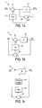
- a source-filter model speechcan be modelled as comprising a signal from a source 402 passed through a time-varying filter 404 .
- the source signalrepresents the immediate vibration of the vocal chords
- the filterrepresents the acoustic effect of the vocal tract formed by the shape of the throat, mouth and tongue.
- the effect of the filteris to alter the frequency profile of the source signal so as to emphasise or diminish certain frequencies.
- speech encodingworks by representing the speech using parameters of a source-filter model.
- the encoded signalwill be divided into a plurality of frames 406 , with each frame comprising a plurality of subframes 408 .
- speechmay be sampled at 16 kHz and processed in frames of 20 ms, with some of the processing done in subframes of 5 ms (four subframes per frame).
- Each framecomprises a flag 407 by which it is classed according to its respective type. Each frame is thus classed at least as either “voiced” or “unvoiced”, and unvoiced frames are encoded differently than voiced frames.
- Each subframe 408then comprises a set of parameters of the source-filter model representative of the sound of the speech in that subframe.
- the source signalhas a degree of long-term periodicity corresponding to the perceived pitch of the voice.
- the source signalcan be modelled as comprising a quasi-periodic signal, with each period corresponding to a respective “pitch pulse” comprising a series of peaks of differing amplitudes.
- the source signalis said to be “quasi” periodic in that on a timescale of at least one subframe it can be taken to have a single, meaningful period which is approximately constant; but over many subframes or frames then the period and form of the signal may change.
- the approximated period at any given pointmay be referred to as the pitch lag.
- An example of a modelled source signal 402is shown schematically in FIG. 4 c with a gradually varying period P 1 , P 2 , P 3 , etc., each comprising a pitch pulse of four peaks which may vary gradually in form and amplitude from one period to the next.
- prediction filteringmay be used to derive a residual signal having less energy that an input speech signal and therefore requiring fewer bits to quantize.
- a short-term prediction filteris used to separate out the speech signal into two separate components: (i) a signal representative of the effect of the time-varying filter 404 ; and (ii) the remaining signal with the effect of the filter 404 removed, which is representative of the source signal.
- the signal representative of the effect of the filter 404may be referred to as the spectral envelope signal, and typically comprises a series of sets of LPC parameters describing the spectral envelope at each stage.
- FIG. 4 dshows a schematic example of a sequence of spectral envelopes 404 1 , 404 2 , 404 3 , etc. varying over time.
- the remaining signal representative of the source alonemay be referred to as the LPC residual signal, as shown schematically in FIG. 4 c .
- the LPC short-term filteringworks by using an LPC analysis to determine a short-term correlation in recently received samples of the speech signal (i.e. short-term compared to the pitch period), then passing coefficients of that correlation to an LPC synthesis filter to predict following samples. The predicted samples are fed back to the input where they are subtracted from the speech signal, thus removing the effect of the spectral envelope and thereby deriving an LTP residual signal representing the modelled source of the speech.
- the LPC residual signalhas less energy that the input speech signal and therefore requiring fewer bits to quantize.
- each subframe 406would contain: (i) a set of parameters representing the spectral envelope 404 ; and (ii) an LPC residual signal representing the source signal 402 with the effect of the short-term correlations removed.
- LPClong-term prediction
- the source signalcan be said to be “quasi” periodic in that on a timescale of at least one correlation calculation it can be taken to have a meaningful period which is approximately (but not exactly) constant; but over many such calculations then the period and form of the source signal may change more significantly.
- a set of parameters derived from this correlationare determined to at least partially represent the source signal for each subframe.
- an LTP analysisis used to determine a correlation between successive received pitch pulses in the LPC residual signal, then coefficients of that correlation are passed to an LTP synthesis filter where they are used to generate a predicted version of the later of those pitch pulses from the last stored one of the preceding pitch pulses.
- the predicted pitch pulseis fed back to the input where it is subtracted from the corresponding portion of the actual LPC residual signal, thus removing the effect of the periodicity and thereby deriving an LTP residual signal.
- the LTP synthesis filteruses a long-term prediction to effectively remove or reduce the pitch pulses from the LPC residual signal, leaving an LTP residual signal having lower energy than the LPC residual.
- the LTP vectors and LTP residual signalare encoded separately for transmission.
- the sets of LPC parameters, the LTP vectors and the LTP residual signalare each quantised prior to transmission (quantisation being the process of converting a continuous range of values into a set of discrete values, or a larger approximately continuous set of discrete values into a smaller set of discrete values).
- quantisationbeing the process of converting a continuous range of values into a set of discrete values, or a larger approximately continuous set of discrete values into a smaller set of discrete values.
- each subframe 406would comprise: (i) a quantised set of LPC parameters representing the spectral envelope, (ii)(a) a quantised LTP vector related to the correlation between pitch periods in the source signal, and (ii)(b) a quantised LTP residual signal representative of the source signal with the effects of this inter-period correlation removed.
- LPClong-term prediction
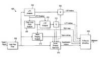
- the encoder 500comprises a high-pass filter 502 , a linear predictive coding (LPC) analysis block 504 , a first vector quantizer 506 , an open-loop pitch analysis block 508 , a long-term prediction (LTP) analysis block 510 , a second vector quantizer 512 , a noise shaping analysis block 514 , a noise shaping quantizer 516 , and an arithmetic encoding block 518 .
- the noise shaping quantizer 516could be of the type of any of the quantizers 200 , 230 or 260 discussed in relation to FIGS. 2 a , 2 b and 2 c respectively.
- the high pass filter 502has an input arranged to receive an input speech signal from an input device such as a microphone, and an output coupled to inputs of the LPC analysis block 504 , noise shaping analysis block 514 and noise shaping quantizer 516 .
- the LPC analysis blockhas an output coupled to an input of the first vector quantizer 506 , and the first vector quantizer 506 has outputs coupled to inputs of the arithmetic encoding block 518 and noise shaping quantizer 516 .
- the LPC analysis block 504has outputs coupled to inputs of the open-loop pitch analysis block 508 and the LTP analysis block 510 .
- the LTP analysis block 510has an output coupled to an input of the second vector quantizer 512
- the second vector quantizer 512has outputs coupled to inputs of the arithmetic encoding block 518 and noise shaping quantizer 516 .
- the open-loop pitch analysis block 508has outputs coupled to inputs of the LTP 510 analysis block 510 and the noise shaping analysis block 514 .
- the noise shaping analysis block 514has outputs coupled to inputs of the arithmetic encoding block 518 and the noise shaping quantizer 516 .
- the noise shaping quantizer 516has an output coupled to an input of the arithmetic encoding block 518 .
- the arithmetic encoding block 518is arranged to produce an output bitstream based on its inputs, for transmission from an output device such as a wired modem or wireless transceiver.
- the encoderprocesses a speech input signal sampled at 16 kHz in frames of 20 milliseconds, with some of the processing done in subframes of 5 milliseconds.
- the output bitsream payloadcontains arithmetically encoded parameters, and has a bitrate that varies depending on a quality setting provided to the encoder and on the complexity and perceptual importance of the input signal.
- the speech input signalis input to the high-pass filter 504 to remove frequencies below 80 Hz which contain almost no speech energy and may contain noise that can be detrimental to the coding efficiency and cause artifacts in the decoded output signal.
- the high-pass filter 504is preferably a second order auto-regressive moving average (ARMA) filter.
- the high-pass filtered input x HPis input to the linear prediction coding (LPC) analysis block 504 , which calculates 16 LPC coefficients a(i) using the covariance method which minimizes the energy of the LPC residual r LPC :
- the LPC coefficientsare transformed to a line spectral frequency (LSF) vector.
- LSFsare quantized using the first vector quantizer 506 , a multi-stage vector quantizer (MSVQ) with 10 stages, producing 10 LSF indices that together represent the quantized LSFs.
- MSVQmulti-stage vector quantizer
- the quantized LSFsare transformed back to produce the quantized LPC coefficients a Q for use in the noise shaping quantizer 516 .
- the LPC residualis input to the open loop pitch analysis block 508 , producing one pitch lag for every 5 millisecond subframe, i.e., four pitch lags per frame.
- the pitch lagsare chosen between 32 and 288 samples, corresponding to pitch frequencies from 56 to 500 Hz, which covers the range found in typical speech signals.
- the pitch analysisproduces a pitch correlation value which is the normalized correlation of the signal in the current frame and the signal delayed by the pitch lag values. Frames for which the correlation value is below a threshold of 0.5 are classified as unvoiced, i.e., containing no periodic signal, whereas all other frames are classified as voiced.
- the pitch lagsare input to the arithmetic coder 518 and noise shaping quantizer 516 .
- LPC residual r LPCis supplied from the LPC analysis block 504 to the LTP analysis block 510 .
- the LTP analysis block 510solves normal equations to find 5 linear prediction filter coefficients b(i) such that the energy in the LTP residual r LTP for that subframe:
- the LTP residualis computed as the LPC residual in the current subframe minus a filtered and delayed LPC residual.
- the LPC residual in the current subframe and the delayed LPC residualare both generated with an LPC analysis filter controlled by the same LPC coefficients. That means that when the LPC coefficients were updated, an LPC residual is computed not only for the current frame but also a new LPC residual is computed for at least lag+2 samples preceding the current frame.
- the LTP coefficients for each frameare quantized using a vector quantizer (VQ).
- VQvector quantizer
- the resulting VQ codebook indexis input to the arithmetic coder, and the quantized LTP coefficients b Q are input to the noise shaping quantizer 516 .
- the high-pass filtered inputis analyzed by the noise shaping analysis block 514 to find filter coefficients and quantization gains used in the noise shaping quantizer.
- the filter coefficientsdetermine the distribution of the coding noise over the spectrum, and are chose such that the quantization is least audible.
- the quantization gainsdetermine the step size of the residual quantizer and as such govern the balance between bitrate and coding noise level.
- All noise shaping parametersare computed and applied per subframe of 5 milliseconds, except for the quantization offset which is determines once per frame of 20 milliseconds.
- a 16 th order noise shaping LPC analysisis performed on a windowed signal block of 16 milliseconds.
- the signal blockhas a look-ahead of 5 milliseconds relative to the current subframe, and the window is an asymmetric sine window.
- the noise shaping LPC analysisis done with the autocorrelation method.
- the quantization gainis found as the square-root of the residual energy from the noise shaping LPC analysis, multiplied by a constant to set the average bitrate to the desired level.
- the quantization gainis further multiplied by 0.5 times the inverse of the pitch correlation determined by the pitch analyses, to reduce the level of coding noise which is more easily audible for voiced signals.
- the quantization gain for each subframeis quantized, and the quantization indices are input to the arithmetically encoder 518 .
- the quantized quantization gainsare input to the noise shaping quantizer 516 .
- the noise shaping analysis block 514determines separate analysis and synthesis noise shaping filter coefficients.
- the short-term and long-term noise shaping coefficientsare determined by the noise shaping analysis block 514 and input to the noise shaping quantizer 516 .
- an adjustment gain Gserves to correct any level mismatch between original and decoded signal that might arise from the noise shaping and de-emphasis.
- This gainis computed as the ratio of the prediction gain of the short-term analysis and synthesis shaping filter coefficients.
- the prediction gain of an LPC synthesis filteris the square-root of the output energy when the filter is excited by a unit-energy impulse on the input.
- the high-pass filtered input x HP (n)is input to the noise shaping quantizer 516 , discussed in more detail in relation to FIG. 6 b below. All gains and filter coefficients and gains are updated for every subframe, except for the LPC coefficients which are updated once per frame.
- noise shaping quantizer 600without separate noise shaping filters at the inputs and outputs is first described in relation to FIG. 6 a.
- the noise shaping quantizer 600comprises a first addition stage 602 , a first subtraction stage 604 , a first amplifier 606 , a quantization unit 608 , a second amplifier 609 , a second addition stage 610 , a shaping filter 612 , a prediction filter 614 and a second subtraction stage 616 .
- the shaping filter 612comprises a third addition stage 618 , a long-term shaping block 620 , a third subtraction stage 622 , and a short-term shaping block 624 .
- the prediction filter 614comprises a fourth addition stage 626 , a long-term prediction block 628 , a fourth subtraction stage 630 , and a short-term prediction block 632 .
- the first addition stage 602has an input that would be arranged to receive the high-pass filtered input from the high-pass filter 502 , and another input coupled to an output of the third addition stage 618 .
- the first subtraction stagehas inputs coupled to outputs of the first addition stage 602 and fourth addition stage 626 .
- the first amplifierhas a signal input coupled to an output of the first subtraction stage and an output coupled to an input of the quantization unit 608 .
- the first amplifier 606also has a control input which would be coupled to the output of the noise shaping analysis block 514 .
- the quantization unit 608has an output coupled to input of the second amplifier 609 and would also have an output coupled to the arithmetic encoding block 518 .
- the second amplifier 609would also have a control input coupled to the output of the noise shaping analysis block 514 , and an output coupled to the an input of the second addition stage 610 .
- the other input of the second addition stage 610is coupled to an output of the fourth addition stage 626 .
- An output of the second addition stageis coupled back to the input of the first addition stage 602 , and to an input of the short-term prediction block 632 and the fourth subtraction stage 630 .
- An output of the short-term prediction block 632is coupled to the other input of the fourth subtraction stage 630 .
- the output of the fourth subtraction stage 630is coupled to the input of the long-term prediction block 628 .
- the fourth addition stage 626has inputs coupled to outputs of the long-term prediction block 628 and short-term prediction block 632 .
- the output of the second addition stage 610is further coupled to an input of the second subtraction stage 616 , and the other input of the second subtraction stage 616 is coupled to the input from the high-pass filter 502 .
- An output of the second subtraction stage 616is coupled to inputs of the short-term shaping block 624 and the third subtraction stage 622 .
- An output of the short-term shaping block 624is coupled to the other input of the third subtraction stage 622 .
- the output of the third subtraction stage 622is coupled to the input of the long-term shaping block 620 .
- the third addition stage 618has inputs coupled to outputs of the long-term shaping block 620 and short-term shaping block 624 .
- the short-term and long-term shaping blocks 624 and 620would each also be coupled to the noise shaping analysis block 514
- the long-term shaping block 620would also be coupled to the open-loop pitch analysis block 508 (connections not shown).
- the short-term prediction block 632would be coupled to the LPC analysis block 504 via the first vector quantizer 506
- the long-term prediction block 628would be coupled to the LTP analysis block 510 via the second vector quantizer 512 (connections also not shown).
- the noise shaping quantizer 600generates a quantized output signal that is identical to the output signal ultimately generated in the decoder.
- the input signalis subtracted from this quantized output signal at the second subtraction stage 616 to obtain the coding noise signal d(n).
- the coding noise signalis input to a shaping filter 612 , described in detail later.
- the output of the shaping filter 612is added to the input signal at the first addition stage 602 in order to effect the spectral shaping of the coding noise.
- the output of the prediction filter 614is subtracted at the first subtraction stage 604 to create a residual signal.
- the residual signalwould be multiplied at the first amplifier 606 by the inverse quantized quantization gain from the noise shaping analysis block 514 , and input to the scalar quantizer 608 .
- the quantization indices of the scalar quantizer 608represent an excitation signal that would be input to the arithmetically encoder 518 .
- the scalar quantizer 608also outputs a quantization signal, which would be multiplied at the second amplifier 609 by the quantized quantization gain from the noise shaping analysis block 514 to create an excitation signal.
- the output of the prediction filter 614is added at the second addition stage to the excitation signal to form the quantized output signal.
- the quantized output signalis input to the prediction filter 614 .
- residualis obtained by subtracting a prediction from the input speech signal.
- excitationis based on only the quantizer output. Often, the residual is simply the quantizer input and the excitation is its output.
- the shaping filter 612inputs the coding noise signal d(n) to a short-term shaping filter 624 , which uses the short-term shaping coefficients a shape to create a short-term shaping signal s short (n), according to the formula:
- the short-term shaping signalis subtracted at the third addition stage 622 from the coding noise signal to create a shaping residual signal f(n).
- the shaping residual signalis input to a long-term shaping filter 620 which uses the long-term shaping coefficients b shape to create a long-term shaping signal s long (n), according to the formula:
- the short-term and long-term shaping signalsare added together at the third addition stage 618 to create the shaping filter output signal.
- the prediction filter 614inputs the quantized output signal y(n) to a short-term prediction filter 632 , which uses the quantized LPC coefficients a i to create a short-term prediction signal p short (n), according to the formula:
- the short-term prediction signalis subtracted at the fourth subtraction stage 630 from the quantized output signal to create an LPC excitation signal e LPC (n).
- the LPC excitation signalis input to a long-term prediction filter 628 which uses the quantized long-term prediction coefficients b i to create a long-term prediction signal p long (n), according to the formula:
- the short-term and long-term prediction signalsare added together at the fourth addition stage 626 to create the prediction filter output signal.
- the LSF indices, LTP indices, quantization gains indices, pitch lags and excitation quantization indiceswould each be arithmetically encoded and multiplexed by the arithmetic encoder 518 to create the payload bitstream.
- noise shaping predictive quantizer 516having separate noise shaping filters at the input and output is now described in relation to FIG. 6 b.
- the noise shaping quantizer 516comprises: a first subtraction stage 652 , a first amplifier 654 , a first addition stage 656 , a second subtraction stage 658 , a second amplifier 660 , a quantization unit 662 , a third amplifier 664 , a second addition stage 666 , a first noise shaping filter in the form of an analysis shaping filter 668 , a second noise shaping filter in the form of a synthesis shaping filter 670 , and a prediction filter 672 .
- the analysis shaping filter 668comprises a third addition stage 674 , a first long-term shaping block 676 , a third subtraction stage 678 , and a first short-term shaping block 680 .
- the synthesis shaping filter 670comprises a fourth addition stage 682 , a second long-term shaping block 684 , a fourth subtraction stage 686 , and a second short-term shaping block 688 .
- the prediction filter 672comprises a fifth addition stage 690 , a long-term prediction block 692 , a fifth subtraction stage 694 , and a short-term prediction block 696 .
- the first subtraction stage 652has an input arranged to receive the high-pass filtered input signal x HP (n) from the high-pass filter 502 . Its other input is coupled to the output of the third addition stage 674 in the analysis shaping filter 668 .
- the output of the first subtraction stage 652is coupled to a signal input of the first amplifier 654 .
- the first amplifieralso has a control input coupled to the noise shaping analysis block 514 .
- the output of the first amplifier 654is coupled to an input of the first addition stage 656 .
- the other input of the first addition stage 656is coupled to the output of the fourth addition stage 682 in the synthesis shaping filter 670 .
- the output of the first addition stage 656is coupled to an input of the second subtraction stage 658 .
- the other input of the second subtraction stage 658is coupled to the output of the fifth addition stage 690 in the prediction filter 672 .
- the output of the second subtraction stage 658is coupled to a signal input of the second amplifier 660 .
- the second amplifier 660also has a control input coupled to the noise shaping analysis block 514 .
- the output of the second amplifier 660is coupled to the input of the quantization unit 662 .
- the quantization unit 662has an output coupled to a signal input of the third amplifier 664 and also has an output coupled to the arithmetic encoding block 518 .
- the third amplifier 664also has a control input coupled to the noise shaping analysis block 514 .
- the output of the third amplifier 664is coupled to an input of the second addition stage 666 .
- the other input of the second addition stage 666is coupled to the output of the fifth addition stage 690 in the prediction filter 672 .
- the output of the second addition stage 666is coupled to the inputs of the short-term prediction block 696 and fifth subtraction stage 694 in the prediction filter 672 , and of the second short-term shaping filter 688 and fourth subtraction stage 686 in the synthesis shaping filter 670 .
- the signal output from the second addition stage 666is the quantized output y(n) fed back to the analysis, synthesis and prediction filters.
- the first short-term shaping block 680 and third subtraction stage 678each have inputs arranged to receive the input signal x HP (n).
- the output of the first short-term shaping block 680is coupled to the other input of the third subtraction stage 678 and an input of the third addition stage 674 .
- the output of the third subtraction stage 678is coupled to the input of the first long-term shaping block 676
- the output of the first short-term shaping block 676is coupled to the other input of the third addition stage 674 .
- the first short-term and long-term shaping blocks 680 and 676are each also coupled to the noise shaping analysis block 514 , and the first long-term shaping block 676 is further coupled to the open-loop pitch analysis block 508 (connections not shown).
- the second short-term shaping block 688 and the fourth subtraction stage 686each have inputs arranged to receive the quantized output signal y(n) from the output of the second addition stage 666 .
- the output of the second short-term shaping block 688is coupled to the other input of the fourth subtraction stage 686 , and to an input of the fourth addition stage 682 .
- the output of the fourth subtraction stage 686is coupled to the input of the second long-term shaping block 684
- the output of the second long-term shaping block 684is coupled to the other input of the fourth addition stage 682 .
- the second short-term and long-term shaping blocks 688 and 684are each also coupled to the noise shaping analysis block 514
- the second long-term shaping block 684is further coupled to the open-loop pitch analysis block 508 (connections not shown).
- the short-term prediction block 696 and fifth subtraction stage 694each have inputs arranged to receive the quantized output signal y(n) from the output of the second addition stage 666 .
- the output of the short-term prediction block 696is coupled to the other input of the fifth subtraction stage 694 , and to an input of the fifth addition stage 690 .
- the output of the fifth subtraction stage 694is coupled to the input of the long-term prediction block 692 , and the output of the long-term prediction block is coupled to the other input of the fifth addition stage 690 .
- the noise shaping quantizer 516generates a quantized output signal y(n) that is identical to the output signal ultimately generated in the decoder.
- the output of the analysis shaping filter 668is subtracted from the input signal x(n) at the first subtraction stage 652 .
- the resultis multiplied by the compensation gain G computed in the noise shaping analysis block 514 .
- the output of the synthesis shaping filter 670is added at the first addition stage 656 , and the output of the prediction filter 672 is subtracted at the second subtraction stage 658 to create a residual signal.
- the residual signalis multiplied by the inverse quantized quantization gain from the noise shaping analysis block 514 , and input to the quantization unit 662 , preferably a scalar quantizer.
- the quantization indices of the quantization unitform a signal that is input to the arithmetic encoder 518 for transmission to a decoder in an encoded signal.
- the quantization unit 662also outputs a quantization signal, which is multiplied at the third amplifier 664 by the quantized quantization gain from the noise shaping analysis block 514 to create an excitation signal.
- the output of the prediction filter 672is added to the excitation signal to form the quantized output signal y(n).
- the quantized output signalis fed back to the prediction filter 672 and synthesis shaping filter 670 .
- the analysis shaping filter 668inputs the input signal x HP (n) to a short-term analysis shaping filter (the first short term shaping block 680 ), which uses the short-term analysis shaping coefficients a shape,ana to create a short-term analysis shaping signal s short,ana (n), according to the formula:
- the short-term analysis shaping signalis subtracted from the input signal x HP (n) at the third subtraction stage 678 to create an analysis shaping residual signal f ana (n).
- the analysis shaping residual signalis input to a long-term analysis shaping filter (the first long-term shaping block 676 ) which uses the long-term shaping coefficients b shape,ana to create a long-term analysis shaping signal s long,ana (n), according to the formula:
- the short-term and long-term analysis shaping signalsare added together at the thiord addition stage 674 to create the analysis shaping filter output signal.
- the synthesis shaping filterinputs 670 the quantized output signal y(n) to a short-term shaping filter (the second short-term shaping block 688 ), which uses the short-term synthesis shaping coefficients a shape,syn to create a short-term synthesis shaping signal s short,syn (n), according to the formula:
- the short-term synthesis shaping signalis subtracted from the quantized output signal y(n) at the fourth subtraction stage 686 to create an synthesis shaping residual signal f syn (n).
- the synthesis shaping residual signalis input to a long-term synthesis shaping filter (the second long-term shaping block 684 ) which uses the long-term shaping coefficients b shape,syn to create a long-term synthesis shaping signal s long,syn (n), according to the formula:
- the short-term and long-term synthesis shaping signalsare added together at the fourth addition stage 682 to create the synthesis shaping filter output signal.
- the prediction filter 672inputs the quantized output signal y(n) to a short-term predictor (the short term prediction block 696 ), which uses the quantized LPC coefficients a Q to create a short-term prediction signal p short (n), according to the formula:
- the short-term prediction signalis subtracted from the quantized output signal y(n) at the fifth subtraction stage 694 to create an LPC excitation signal e LPC (n):
- the LPC excitation signalis input to a long-term predictor (long term prediction block 692 ) which uses the quantized long-term prediction coefficients b Q to create a long-term prediction signal p long (n), according to the formula:
- the short-term and long-term prediction signalsare added together at the fifth addition stage 690 to create the prediction filter output signal.
- the LSF indices, LTP indices, quantization gains indices, pitch lags, and excitation quantization indicesare each arithmetically encoded and multiplexed by the arithmetic encoder 518 to create the payload bitstream.
- the arithmetic encoder 518uses a look-up table with probability values for each index.
- the look-up tablesare created by running a database of speech training signals and measuring frequencies of each of the index values. The frequencies are translated into probabilities through a normalization step.
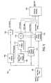
- a predictive speech decoder 700 for use in decoding such a signalis now discussed in relation to FIGS. 7 a and 7 b.
- the decoder 700comprises an arithmetic decoding and dequantizing block 702 , an excitation generation block 704 , an LTP synthesis filter 706 , and an LPC synthesis filter 708 .
- the arithmetic decoding and dequantizing blockhas an input arranged to receive an encoded bitstream from an input device such as a wired modem or wireless transceiver, and has outputs coupled to inputs of each of the excitation generation block 704 , LTP synthesis filter 706 and LPC synthesis filter 708 .
- the excitation generation block 704has an output coupled to an input of the LTP synthesis filter 706
- the LTP synthesis filter 706has an output connected to an input of the LPC synthesis filter 708 .
- the LPC synthesis filterhas an output arranged to provide a decoded output for supply to an output device such as a speaker or headphones.
- the arithmetically encoded bitstreamis demultiplexed and decoded to create LSF indices, LTP indices, quantization gains indices, pitch lags and a signal of excitation quantization indices.
- the LSF indicesare converted to quantized LSFs by adding the codebook vectors of the ten stages of the MSVQ.
- the quantized LSFsare transformed to quantized LPC coefficients.
- the LTP indicesare converted to quantized LTP coefficients.
- the gains indicesare converted to quantization gains, through look ups in the gain quantization codebook.
- the quantization indicesare input to the excitation generator 704 which generates an excitation signal.
- the excitation quantization indicesare multiplied with the quantized quantization gain to produce the excitation signal e(n).
- the excitation signal e(n)is input to the LTP synthesis filter 706 to create the LPC excitation signal e LPC (n).
- the output of a long term predictor 710 in the LTP synthesis filter 708is added to the excitation signal, which creates the LPC excitation signal e LPC (n) according to:
- the LPC excitation signalis input to the LPC synthesis filter 708 , preferably a strictly causal MA filter controlled by the pitch lag and quantized LTP coefficients, to create the decoded speech signal y(n).
- the output of a short term predictor 712 in the LPC synthesis filter 708is added to the LPC excitation signal, which creates the quantized output signal according to:
- the encoder 500 and decoder 700are preferably implemented in software, such that each of the components 502 to 518 , 652 to 696 , and 702 to 712 comprise modules of software stored on one or more memory devices and executed on a processor.
- a preferred application of the present inventionis to encode speech for transmission over a packet-based network such as the Internet, preferably using a peer-to-peer (P2P) system implemented over the Internet, for example as part of a live call such as a Voice over IP (VoIP) call.
- P2Ppeer-to-peer
- VoIPVoice over IP
- the encoder 500 and decoder 700are preferably implemented in client application software executed on end-user terminals of two users communicating over the P2P system.
- the above embodimentsare described only by way of example.
- some or all of the modules of the encoder and/or decodercould be implemented in dedicated hardware units.
- the inventionis not limited to use in a client application, but could be used for any other speech-related purpose such as cellular mobile telephony.
- the input speech signalcould be received by the encoder from some other source such as a storage device and potentially be transcoded from some other form by the encoder; and/or instead of a user output device such as a speaker or headphones, the output signal from the decoder could be sent to another source such as a storage device and potentially be transcoded into some other form by the decoder.
- Other applications and configurationsmay be apparent to the person skilled in the art given the disclosure herein. The scope of the invention is not limited by the described embodiments, but only by the following claims.
Landscapes
- Engineering & Computer Science (AREA)
- Physics & Mathematics (AREA)
- Computational Linguistics (AREA)
- Signal Processing (AREA)
- Health & Medical Sciences (AREA)
- Audiology, Speech & Language Pathology (AREA)
- Human Computer Interaction (AREA)
- Acoustics & Sound (AREA)
- Multimedia (AREA)
- Spectroscopy & Molecular Physics (AREA)
- Compression, Expansion, Code Conversion, And Decoders (AREA)
Abstract
Description
Y(z)=X(z)+(1+F(z))·Q(z)
- receive an input signal representing a property of speech;
- quantize the input signal, thus generating a quantized output signal;
- prior to said quantization, filter a version of the input signal using a first noise shaping filter having a first set of filter coefficients, thus generating a first filtered signal based on that version of the input signal and the first set of filter coefficients;
- following said quantization, filter a version of the quantized output signal using a second noise shaping filter having a second set of filter coefficients different than said first set, thus generating a second filter signal based on that version of the quantized output signal and the second set of filter coefficients;
- perform a noise shaping operation to control a frequency spectrum of a noise effect in the quantized output signal caused by said quantization, wherein the noise shaping operation is performed based on both the first and second filtered signals; and
- output the quantised output signal in an encoded signal.
is minimized. The normal equations are solved as:
b=WLTP−1CLTP,
where WLTPis a weighting matrix containing correlation values
and CLTPis a correlation vector:
ashape,ana(i)=aautocorr(i)ganai
and
ashape,syn(i)=aautocorr(i)gsyni
bshape,ana=0.4sqrt(PitchCorrelation)[0.25,0.5,0.25]
and
bshape,syn=0.5sqrt(PitchCorrelation)[0.25,0.5,0.25].
where rkare the reflection coefficients.
using the pitch lag and quantized LTP coefficients bQ.
using the quantized LPC coefficients aQ.
Claims (21)
Priority Applications (3)
| Application Number | Priority Date | Filing Date | Title |
|---|---|---|---|
| US13/905,864US8639504B2 (en) | 2009-01-06 | 2013-05-30 | Speech encoding utilizing independent manipulation of signal and noise spectrum |
| US14/162,707US8849658B2 (en) | 2009-01-06 | 2014-01-23 | Speech encoding utilizing independent manipulation of signal and noise spectrum |
| US14/459,984US10026411B2 (en) | 2009-01-06 | 2014-08-14 | Speech encoding utilizing independent manipulation of signal and noise spectrum |
Applications Claiming Priority (2)
| Application Number | Priority Date | Filing Date | Title |
|---|---|---|---|
| GB0900143.9AGB2466673B (en) | 2009-01-06 | 2009-01-06 | Quantization |
| GB0900143.9 | 2009-01-06 |
Related Child Applications (1)
| Application Number | Title | Priority Date | Filing Date |
|---|---|---|---|
| US13/905,864ContinuationUS8639504B2 (en) | 2009-01-06 | 2013-05-30 | Speech encoding utilizing independent manipulation of signal and noise spectrum |
Publications (2)
| Publication Number | Publication Date |
|---|---|
| US20100174541A1 US20100174541A1 (en) | 2010-07-08 |
| US8463604B2true US8463604B2 (en) | 2013-06-11 |
Family
ID=40379222
Family Applications (4)
| Application Number | Title | Priority Date | Filing Date |
|---|---|---|---|
| US12/455,100Active2031-08-10US8463604B2 (en) | 2009-01-06 | 2009-05-28 | Speech encoding utilizing independent manipulation of signal and noise spectrum |
| US13/905,864ActiveUS8639504B2 (en) | 2009-01-06 | 2013-05-30 | Speech encoding utilizing independent manipulation of signal and noise spectrum |
| US14/162,707ActiveUS8849658B2 (en) | 2009-01-06 | 2014-01-23 | Speech encoding utilizing independent manipulation of signal and noise spectrum |
| US14/459,984ActiveUS10026411B2 (en) | 2009-01-06 | 2014-08-14 | Speech encoding utilizing independent manipulation of signal and noise spectrum |
Family Applications After (3)
| Application Number | Title | Priority Date | Filing Date |
|---|---|---|---|
| US13/905,864ActiveUS8639504B2 (en) | 2009-01-06 | 2013-05-30 | Speech encoding utilizing independent manipulation of signal and noise spectrum |
| US14/162,707ActiveUS8849658B2 (en) | 2009-01-06 | 2014-01-23 | Speech encoding utilizing independent manipulation of signal and noise spectrum |
| US14/459,984ActiveUS10026411B2 (en) | 2009-01-06 | 2014-08-14 | Speech encoding utilizing independent manipulation of signal and noise spectrum |
Country Status (4)
| Country | Link |
|---|---|
| US (4) | US8463604B2 (en) |
| EP (1) | EP2384503B1 (en) |
| GB (1) | GB2466673B (en) |
| WO (1) | WO2010079170A1 (en) |
Cited By (6)
| Publication number | Priority date | Publication date | Assignee | Title |
|---|---|---|---|---|
| US20100174532A1 (en)* | 2009-01-06 | 2010-07-08 | Koen Bernard Vos | Speech encoding |
| US20100174542A1 (en)* | 2009-01-06 | 2010-07-08 | Skype Limited | Speech coding |
| US20100174538A1 (en)* | 2009-01-06 | 2010-07-08 | Koen Bernard Vos | Speech encoding |
| US8639504B2 (en) | 2009-01-06 | 2014-01-28 | Skype | Speech encoding utilizing independent manipulation of signal and noise spectrum |
| US20170178649A1 (en)* | 2014-03-28 | 2017-06-22 | Samsung Electronics Co., Ltd. | Method and device for quantization of linear prediction coefficient and method and device for inverse quantization |
| US11295750B2 (en)* | 2018-09-27 | 2022-04-05 | Fraunhofer-Gesellschaft zur Förderung der angewandten Forschung e.V. | Apparatus and method for noise shaping using subspace projections for low-rate coding of speech and audio |
Families Citing this family (22)
| Publication number | Priority date | Publication date | Assignee | Title |
|---|---|---|---|---|
| GB2466674B (en) | 2009-01-06 | 2013-11-13 | Skype | Speech coding |
| GB2466672B (en) | 2009-01-06 | 2013-03-13 | Skype | Speech coding |
| GB2466669B (en) | 2009-01-06 | 2013-03-06 | Skype | Speech coding |
| US8452606B2 (en) | 2009-09-29 | 2013-05-28 | Skype | Speech encoding using multiple bit rates |
| US9591374B2 (en) | 2010-06-30 | 2017-03-07 | Warner Bros. Entertainment Inc. | Method and apparatus for generating encoded content using dynamically optimized conversion for 3D movies |
| US10326978B2 (en) | 2010-06-30 | 2019-06-18 | Warner Bros. Entertainment Inc. | Method and apparatus for generating virtual or augmented reality presentations with 3D audio positioning |
| US8917774B2 (en)* | 2010-06-30 | 2014-12-23 | Warner Bros. Entertainment Inc. | Method and apparatus for generating encoded content using dynamically optimized conversion |
| US8755432B2 (en) | 2010-06-30 | 2014-06-17 | Warner Bros. Entertainment Inc. | Method and apparatus for generating 3D audio positioning using dynamically optimized audio 3D space perception cues |
| US9082416B2 (en)* | 2010-09-16 | 2015-07-14 | Qualcomm Incorporated | Estimating a pitch lag |
| BR112013020769B1 (en) | 2011-02-16 | 2021-03-09 | Dolby Laboratories Licensing Corporation | method for encoding an incoming audio signal using a prediction filter, audio encoding device and audio decoding device |
| KR20130032980A (en)* | 2011-09-26 | 2013-04-03 | 한국전자통신연구원 | Coding apparatus and method using residual bits |
| US9842598B2 (en)* | 2013-02-21 | 2017-12-12 | Qualcomm Incorporated | Systems and methods for mitigating potential frame instability |
| US10148468B2 (en)* | 2015-06-01 | 2018-12-04 | Huawei Technologies Co., Ltd. | Configurable architecture for generating a waveform |
| JP6932439B2 (en)* | 2017-07-11 | 2021-09-08 | 日本無線株式会社 | Digital signal processor |
| EP3483884A1 (en) | 2017-11-10 | 2019-05-15 | Fraunhofer-Gesellschaft zur Förderung der angewandten Forschung e.V. | Signal filtering |
| WO2019091576A1 (en) | 2017-11-10 | 2019-05-16 | Fraunhofer-Gesellschaft zur Förderung der angewandten Forschung e.V. | Audio encoders, audio decoders, methods and computer programs adapting an encoding and decoding of least significant bits |
| EP3483883A1 (en) | 2017-11-10 | 2019-05-15 | Fraunhofer-Gesellschaft zur Förderung der angewandten Forschung e.V. | Audio coding and decoding with selective postfiltering |
| EP3483878A1 (en) | 2017-11-10 | 2019-05-15 | Fraunhofer-Gesellschaft zur Förderung der angewandten Forschung e.V. | Audio decoder supporting a set of different loss concealment tools |
| EP3483879A1 (en) | 2017-11-10 | 2019-05-15 | Fraunhofer-Gesellschaft zur Förderung der angewandten Forschung e.V. | Analysis/synthesis windowing function for modulated lapped transformation |
| EP3483882A1 (en) | 2017-11-10 | 2019-05-15 | Fraunhofer-Gesellschaft zur Förderung der angewandten Forschung e.V. | Controlling bandwidth in encoders and/or decoders |
| EP3483886A1 (en) | 2017-11-10 | 2019-05-15 | Fraunhofer-Gesellschaft zur Förderung der angewandten Forschung e.V. | Selecting pitch lag |
| EP3483880A1 (en) | 2017-11-10 | 2019-05-15 | Fraunhofer-Gesellschaft zur Förderung der angewandten Forschung e.V. | Temporal noise shaping |
Citations (90)
| Publication number | Priority date | Publication date | Assignee | Title |
|---|---|---|---|---|
| US4857927A (en) | 1985-12-27 | 1989-08-15 | Yamaha Corporation | Dither circuit having dither level changing function |
| US5125030A (en)* | 1987-04-13 | 1992-06-23 | Kokusai Denshin Denwa Co., Ltd. | Speech signal coding/decoding system based on the type of speech signal |
| EP0501421A2 (en) | 1991-02-26 | 1992-09-02 | Nec Corporation | Speech coding system |
| EP0550990A2 (en) | 1992-01-07 | 1993-07-14 | Hewlett-Packard Company | Combined and simplified multiplexing with dithered analog to digital converter |
| US5240386A (en) | 1989-06-06 | 1993-08-31 | Ford Motor Company | Multiple stage orbiting ring rotary compressor |
| US5253269A (en) | 1991-09-05 | 1993-10-12 | Motorola, Inc. | Delta-coded lag information for use in a speech coder |
| US5327250A (en) | 1989-03-31 | 1994-07-05 | Canon Kabushiki Kaisha | Facsimile device |
| EP0610906A1 (en) | 1993-02-09 | 1994-08-17 | Nec Corporation | Device for encoding speech spectrum parameters with a smallest possible number of bits |
| US5357252A (en) | 1993-03-22 | 1994-10-18 | Motorola, Inc. | Sigma-delta modulator with improved tone rejection and method therefor |
| US5487086A (en) | 1991-09-13 | 1996-01-23 | Comsat Corporation | Transform vector quantization for adaptive predictive coding |
| EP0720145A2 (en) | 1994-12-27 | 1996-07-03 | Nec Corporation | Speech pitch lag coding apparatus and method |
| EP0724252A2 (en) | 1994-12-27 | 1996-07-31 | Nec Corporation | A CELP-type speech encoder having an improved long-term predictor |
| US5646961A (en)* | 1994-12-30 | 1997-07-08 | Lucent Technologies Inc. | Method for noise weighting filtering |
| US5649054A (en) | 1993-12-23 | 1997-07-15 | U.S. Philips Corporation | Method and apparatus for coding digital sound by subtracting adaptive dither and inserting buried channel bits and an apparatus for decoding such encoding digital sound |
| US5680508A (en) | 1991-05-03 | 1997-10-21 | Itt Corporation | Enhancement of speech coding in background noise for low-rate speech coder |
| EP0849724A2 (en) | 1996-12-18 | 1998-06-24 | Nec Corporation | High quality speech coder and coding method |
| US5774842A (en) | 1995-04-20 | 1998-06-30 | Sony Corporation | Noise reduction method and apparatus utilizing filtering of a dithered signal |
| EP0877355A2 (en) | 1997-05-07 | 1998-11-11 | Nokia Mobile Phones Ltd. | Speech coding |
| US5867814A (en) | 1995-11-17 | 1999-02-02 | National Semiconductor Corporation | Speech coder that utilizes correlation maximization to achieve fast excitation coding, and associated coding method |
| EP0957472A2 (en) | 1998-05-11 | 1999-11-17 | Nec Corporation | Speech coding apparatus and speech decoding apparatus |
| US6104992A (en) | 1998-08-24 | 2000-08-15 | Conexant Systems, Inc. | Adaptive gain reduction to produce fixed codebook target signal |
| US6122608A (en) | 1997-08-28 | 2000-09-19 | Texas Instruments Incorporated | Method for switched-predictive quantization |
| US6173257B1 (en) | 1998-08-24 | 2001-01-09 | Conexant Systems, Inc | Completed fixed codebook for speech encoder |
| US6188980B1 (en) | 1998-08-24 | 2001-02-13 | Conexant Systems, Inc. | Synchronized encoder-decoder frame concealment using speech coding parameters including line spectral frequencies and filter coefficients |
| EP1093116A1 (en) | 1994-08-02 | 2001-04-18 | Nec Corporation | Autocorrelation based search loop for CELP speech coder |
| US20010001320A1 (en) | 1998-05-29 | 2001-05-17 | Stefan Heinen | Method and device for speech coding |
| US20010005822A1 (en) | 1999-12-13 | 2001-06-28 | Fujitsu Limited | Noise suppression apparatus realized by linear prediction analyzing circuit |
| US6260010B1 (en) | 1998-08-24 | 2001-07-10 | Conexant Systems, Inc. | Speech encoder using gain normalization that combines open and closed loop gains |
| US20010039491A1 (en) | 1996-11-07 | 2001-11-08 | Matsushita Electric Industrial Co., Ltd. | Excitation vector generator, speech coder and speech decoder |
| CN1337042A (en) | 1999-01-08 | 2002-02-20 | 诺基亚移动电话有限公司 | Method and apparatus for determining speech coding parameters |
| US20020032571A1 (en) | 1996-09-25 | 2002-03-14 | Ka Y. Leung | Method and apparatus for storing digital audio and playback thereof |
| US6363119B1 (en) | 1998-03-05 | 2002-03-26 | Nec Corporation | Device and method for hierarchically coding/decoding images reversibly and with improved coding efficiency |
| US6408268B1 (en) | 1997-03-12 | 2002-06-18 | Mitsubishi Denki Kabushiki Kaisha | Voice encoder, voice decoder, voice encoder/decoder, voice encoding method, voice decoding method and voice encoding/decoding method |
| US20020120438A1 (en) | 1993-12-14 | 2002-08-29 | Interdigital Technology Corporation | Receiver for receiving a linear predictive coded speech signal |
| US6456964B2 (en) | 1998-12-21 | 2002-09-24 | Qualcomm, Incorporated | Encoding of periodic speech using prototype waveforms |
| US6470309B1 (en) | 1998-05-08 | 2002-10-22 | Texas Instruments Incorporated | Subframe-based correlation |
| EP1255244A1 (en) | 2001-05-04 | 2002-11-06 | Nokia Corporation | Memory addressing in the decoding of an audio signal |
| US6493665B1 (en) | 1998-08-24 | 2002-12-10 | Conexant Systems, Inc. | Speech classification and parameter weighting used in codebook search |
| US6502069B1 (en) | 1997-10-24 | 2002-12-31 | Fraunhofer-Gesellschaft Zur Forderung Der Angewandten Forschung E.V. | Method and a device for coding audio signals and a method and a device for decoding a bit stream |
| US6523002B1 (en) | 1999-09-30 | 2003-02-18 | Conexant Systems, Inc. | Speech coding having continuous long term preprocessing without any delay |
| US6574593B1 (en) | 1999-09-22 | 2003-06-03 | Conexant Systems, Inc. | Codebook tables for encoding and decoding |
| EP1326235A2 (en) | 2002-01-04 | 2003-07-09 | Broadcom Corporation | Efficient excitation quantization in noise feedback coding with general noise shaping |
| US20030200092A1 (en) | 1999-09-22 | 2003-10-23 | Yang Gao | System of encoding and decoding speech signals |
| US20040102969A1 (en) | 1998-12-21 | 2004-05-27 | Sharath Manjunath | Variable rate speech coding |
| US6757654B1 (en) | 2000-05-11 | 2004-06-29 | Telefonaktiebolaget Lm Ericsson | Forward error correction in speech coding |
| US6775649B1 (en) | 1999-09-01 | 2004-08-10 | Texas Instruments Incorporated | Concealment of frame erasures for speech transmission and storage system and method |
| US6862567B1 (en) | 2000-08-30 | 2005-03-01 | Mindspeed Technologies, Inc. | Noise suppression in the frequency domain by adjusting gain according to voicing parameters |
| US20050141721A1 (en) | 2002-04-10 | 2005-06-30 | Koninklijke Phillips Electronics N.V. | Coding of stereo signals |
| CN1653521A (en) | 2002-03-12 | 2005-08-10 | 迪里辛姆网络控股有限公司 | Method for adaptive codebook pitch-lag computation in audio transcoders |
| US20050278169A1 (en) | 2003-04-01 | 2005-12-15 | Hardwick John C | Half-rate vocoder |
| US20050285765A1 (en) | 2004-06-24 | 2005-12-29 | Sony Corporation | Delta-sigma modulator and delta-sigma modulation method |
| US6996523B1 (en) | 2001-02-13 | 2006-02-07 | Hughes Electronics Corporation | Prototype waveform magnitude quantization for a frequency domain interpolative speech codec system |
| US20060074643A1 (en) | 2004-09-22 | 2006-04-06 | Samsung Electronics Co., Ltd. | Apparatus and method of encoding/decoding voice for selecting quantization/dequantization using characteristics of synthesized voice |
| US20060271356A1 (en) | 2005-04-01 | 2006-11-30 | Vos Koen B | Systems, methods, and apparatus for quantization of spectral envelope representation |
| US7149683B2 (en) | 2002-12-24 | 2006-12-12 | Nokia Corporation | Method and device for robust predictive vector quantization of linear prediction parameters in variable bit rate speech coding |
| US7151802B1 (en)* | 1998-10-27 | 2006-12-19 | Voiceage Corporation | High frequency content recovering method and device for over-sampled synthesized wideband signal |
| US7171355B1 (en) | 2000-10-25 | 2007-01-30 | Broadcom Corporation | Method and apparatus for one-stage and two-stage noise feedback coding of speech and audio signals |
| US20070043560A1 (en) | 2001-05-23 | 2007-02-22 | Samsung Electronics Co., Ltd. | Excitation codebook search method in a speech coding system |
| EP1758101A1 (en) | 2001-12-14 | 2007-02-28 | Nokia Corporation | Signal modification method for efficient coding of speech signals |
| US20070055503A1 (en) | 2002-10-29 | 2007-03-08 | Docomo Communications Laboratories Usa, Inc. | Optimized windows and interpolation factors, and methods for optimizing windows, interpolation factors and linear prediction analysis in the ITU-T G.729 speech coding standard |
| US20070088543A1 (en) | 2000-01-11 | 2007-04-19 | Matsushita Electric Industrial Co., Ltd. | Multimode speech coding apparatus and decoding apparatus |
| US20070136057A1 (en) | 2005-12-14 | 2007-06-14 | Phillips Desmond K | Preamble detection |
| US20070225971A1 (en) | 2004-02-18 | 2007-09-27 | Bruno Bessette | Methods and devices for low-frequency emphasis during audio compression based on ACELP/TCX |
| JP2007279754A (en) | 1999-08-23 | 2007-10-25 | Matsushita Electric Ind Co Ltd | Speech encoding device |
| US20070255561A1 (en) | 1998-09-18 | 2007-11-01 | Conexant Systems, Inc. | System for speech encoding having an adaptive encoding arrangement |
| US20080004869A1 (en)* | 2006-06-30 | 2008-01-03 | Juergen Herre | Audio Encoder, Audio Decoder and Audio Processor Having a Dynamically Variable Warping Characteristic |
| US20080015866A1 (en) | 2006-07-12 | 2008-01-17 | Broadcom Corporation | Interchangeable noise feedback coding and code excited linear prediction encoders |
| EP1903558A2 (en) | 2006-09-20 | 2008-03-26 | Fujitsu Limited | Audio signal interpolation method and device |
| US20080091418A1 (en) | 2006-10-13 | 2008-04-17 | Nokia Corporation | Pitch lag estimation |
| WO2008046492A1 (en) | 2006-10-20 | 2008-04-24 | Dolby Sweden Ab | Apparatus and method for encoding an information signal |
| WO2008056775A1 (en) | 2006-11-10 | 2008-05-15 | Panasonic Corporation | Parameter decoding device, parameter encoding device, and parameter decoding method |
| US20080126084A1 (en) | 2006-11-28 | 2008-05-29 | Samsung Electroncis Co., Ltd. | Method, apparatus and system for encoding and decoding broadband voice signal |
| US20080140426A1 (en) | 2006-09-29 | 2008-06-12 | Dong Soo Kim | Methods and apparatuses for encoding and decoding object-based audio signals |
| US20080154588A1 (en) | 2006-12-26 | 2008-06-26 | Yang Gao | Speech Coding System to Improve Packet Loss Concealment |
| US20090043574A1 (en) | 1999-09-22 | 2009-02-12 | Conexant Systems, Inc. | Speech coding system and method using bi-directional mirror-image predicted pulses |
| US7505594B2 (en) | 2000-12-19 | 2009-03-17 | Qualcomm Incorporated | Discontinuous transmission (DTX) controller system and method |
| JP4312000B2 (en) | 2003-07-23 | 2009-08-12 | パナソニック株式会社 | Buck-boost DC-DC converter |
| US20090222273A1 (en) | 2006-02-22 | 2009-09-03 | France Telecom | Coding/Decoding of a Digital Audio Signal, in Celp Technique |
| US7684981B2 (en) | 2005-07-15 | 2010-03-23 | Microsoft Corporation | Prediction of spectral coefficients in waveform coding and decoding |
| GB2466672A (en) | 2009-01-06 | 2010-07-07 | Skype Ltd | Modifying the LTP state synchronously in the encoder and decoder when LPC coefficients are updated |
| GB2466671A (en) | 2009-01-06 | 2010-07-07 | Skype Ltd | Speech Encoding |
| GB2466674A (en) | 2009-01-06 | 2010-07-07 | Skype Ltd | Speech coding |
| GB2466669A (en) | 2009-01-06 | 2010-07-07 | Skype Ltd | Encoding speech for transmission over a transmission medium taking into account pitch lag |
| GB2466673A (en) | 2009-01-06 | 2010-07-07 | Skype Ltd | Manipulating signal spectrum and coding noise spectrums separately with different coefficients pre and post quantization |
| GB2466670A (en) | 2009-01-06 | 2010-07-07 | Skype Ltd | Transmit line spectral frequency vector and interpolation factor determination in speech encoding |
| US20100174542A1 (en) | 2009-01-06 | 2010-07-08 | Skype Limited | Speech coding |
| US20100174531A1 (en) | 2009-01-06 | 2010-07-08 | Skype Limited | Speech coding |
| US7869993B2 (en) | 2003-10-07 | 2011-01-11 | Ojala Pasi S | Method and a device for source coding |
| US20110077940A1 (en) | 2009-09-29 | 2011-03-31 | Koen Bernard Vos | Speech encoding |
| US20110173004A1 (en)* | 2007-06-14 | 2011-07-14 | Bruno Bessette | Device and Method for Noise Shaping in a Multilayer Embedded Codec Interoperable with the ITU-T G.711 Standard |
Family Cites Families (29)
| Publication number | Priority date | Publication date | Assignee | Title |
|---|---|---|---|---|
| US4605961A (en) | 1983-12-22 | 1986-08-12 | Frederiksen Jeffrey E | Video transmission system using time-warp scrambling |
| EP0163829B1 (en) | 1984-03-21 | 1989-08-23 | Nippon Telegraph And Telephone Corporation | Speech signal processing system |
| US4916449A (en) | 1985-07-09 | 1990-04-10 | Teac Corporation | Wide dynamic range digital to analog conversion method and system |
| US4922537A (en) | 1987-06-02 | 1990-05-01 | Frederiksen & Shu Laboratories, Inc. | Method and apparatus employing audio frequency offset extraction and floating-point conversion for digitally encoding and decoding high-fidelity audio signals |
| JPH0783316B2 (en) | 1987-10-30 | 1995-09-06 | 日本電信電話株式会社 | Mass vector quantization method and apparatus thereof |
| JPH0228740A (en) | 1988-07-18 | 1990-01-30 | Mitsubishi Electric Corp | data transfer processing device |
| ATE191987T1 (en) | 1989-09-01 | 2000-05-15 | Motorola Inc | NUMERICAL VOICE ENCODER WITH IMPROVED LONG-TERM PREDICTION THROUGH SUB-SAMPLING RESOLUTION |
| JP2667924B2 (en) | 1990-05-25 | 1997-10-27 | 東芝テスコ 株式会社 | Aircraft docking guidance device |
| GB9216659D0 (en) | 1992-08-05 | 1992-09-16 | Gerzon Michael A | Subtractively dithered digital waveform coding system |
| JPH06306699A (en) | 1993-04-23 | 1994-11-01 | Nippon Steel Corp | Electrolytic polishing method for stainless steel |
| IT1270438B (en) | 1993-06-10 | 1997-05-05 | Sip | PROCEDURE AND DEVICE FOR THE DETERMINATION OF THE FUNDAMENTAL TONE PERIOD AND THE CLASSIFICATION OF THE VOICE SIGNAL IN NUMERICAL CODERS OF THE VOICE |
| JPH08179796A (en) | 1994-12-21 | 1996-07-12 | Sony Corp | Voice coding method |
| GB9509831D0 (en)* | 1995-05-15 | 1995-07-05 | Gerzon Michael A | Lossless coding method for waveform data |
| FI973873A7 (en) | 1997-10-02 | 1999-04-03 | Nokia Mobile Phones Ltd | Speech coding |
| US6141639A (en)* | 1998-06-05 | 2000-10-31 | Conexant Systems, Inc. | Method and apparatus for coding of signals containing speech and background noise |
| EP1370114A3 (en) | 1999-04-07 | 2004-03-17 | Dolby Laboratories Licensing Corporation | Matrix improvements to lossless encoding and decoding |
| FI116992B (en) | 1999-07-05 | 2006-04-28 | Nokia Corp | Methods, systems, and devices for enhancing audio coding and transmission |
| US6782360B1 (en) | 1999-09-22 | 2004-08-24 | Mindspeed Technologies, Inc. | Gain quantization for a CELP speech coder |
| US20020049586A1 (en) | 2000-09-11 | 2002-04-25 | Kousuke Nishio | Audio encoder, audio decoder, and broadcasting system |
| US6856961B2 (en) | 2001-02-13 | 2005-02-15 | Mindspeed Technologies, Inc. | Speech coding system with input signal transformation |
| GB0110449D0 (en)* | 2001-04-28 | 2001-06-20 | Genevac Ltd | Improvements in and relating to the heating of microtitre well plates in centrifugal evaporators |
| US7143032B2 (en) | 2001-08-17 | 2006-11-28 | Broadcom Corporation | Method and system for an overlap-add technique for predictive decoding based on extrapolation of speech and ringinig waveform |
| US7206740B2 (en) | 2002-01-04 | 2007-04-17 | Broadcom Corporation | Efficient excitation quantization in noise feedback coding with general noise shaping |
| EP1630790B1 (en) | 2003-05-20 | 2008-09-03 | Matsushita Electric Industrial Co., Ltd. | Method and device for extending the audio signal band |
| WO2005009019A2 (en) | 2003-07-16 | 2005-01-27 | Skype Limited | Peer-to-peer telephone system and method |
| WO2006116024A2 (en) | 2005-04-22 | 2006-11-02 | Qualcomm Incorporated | Systems, methods, and apparatus for gain factor attenuation |
| US7930176B2 (en) | 2005-05-20 | 2011-04-19 | Broadcom Corporation | Packet loss concealment for block-independent speech codecs |
| US7778476B2 (en) | 2005-10-21 | 2010-08-17 | Maxim Integrated Products, Inc. | System and method for transform coding randomization |
| US8682652B2 (en)* | 2006-06-30 | 2014-03-25 | Fraunhofer-Gesellschaft Zur Foerderung Der Angewandten Forschung E.V. | Audio encoder, audio decoder and audio processor having a dynamically variable warping characteristic |
- 2009
- 2009-01-06GBGB0900143.9Apatent/GB2466673B/ennot_activeExpired - Fee Related
- 2009-05-28USUS12/455,100patent/US8463604B2/enactiveActive
- 2010
- 2010-01-05WOPCT/EP2010/050060patent/WO2010079170A1/enactiveApplication Filing
- 2010-01-05EPEP10700158.8Apatent/EP2384503B1/enactiveActive
- 2013
- 2013-05-30USUS13/905,864patent/US8639504B2/enactiveActive
- 2014
- 2014-01-23USUS14/162,707patent/US8849658B2/enactiveActive
- 2014-08-14USUS14/459,984patent/US10026411B2/enactiveActive
Patent Citations (118)
| Publication number | Priority date | Publication date | Assignee | Title |
|---|---|---|---|---|
| US4857927A (en) | 1985-12-27 | 1989-08-15 | Yamaha Corporation | Dither circuit having dither level changing function |
| US5125030A (en)* | 1987-04-13 | 1992-06-23 | Kokusai Denshin Denwa Co., Ltd. | Speech signal coding/decoding system based on the type of speech signal |
| US5327250A (en) | 1989-03-31 | 1994-07-05 | Canon Kabushiki Kaisha | Facsimile device |
| US5240386A (en) | 1989-06-06 | 1993-08-31 | Ford Motor Company | Multiple stage orbiting ring rotary compressor |
| EP0501421A2 (en) | 1991-02-26 | 1992-09-02 | Nec Corporation | Speech coding system |
| US5680508A (en) | 1991-05-03 | 1997-10-21 | Itt Corporation | Enhancement of speech coding in background noise for low-rate speech coder |
| US5253269A (en) | 1991-09-05 | 1993-10-12 | Motorola, Inc. | Delta-coded lag information for use in a speech coder |
| US5487086A (en) | 1991-09-13 | 1996-01-23 | Comsat Corporation | Transform vector quantization for adaptive predictive coding |
| EP0550990A2 (en) | 1992-01-07 | 1993-07-14 | Hewlett-Packard Company | Combined and simplified multiplexing with dithered analog to digital converter |
| EP0610906A1 (en) | 1993-02-09 | 1994-08-17 | Nec Corporation | Device for encoding speech spectrum parameters with a smallest possible number of bits |
| US5357252A (en) | 1993-03-22 | 1994-10-18 | Motorola, Inc. | Sigma-delta modulator with improved tone rejection and method therefor |
| US20020120438A1 (en) | 1993-12-14 | 2002-08-29 | Interdigital Technology Corporation | Receiver for receiving a linear predictive coded speech signal |
| US5649054A (en) | 1993-12-23 | 1997-07-15 | U.S. Philips Corporation | Method and apparatus for coding digital sound by subtracting adaptive dither and inserting buried channel bits and an apparatus for decoding such encoding digital sound |
| EP1093116A1 (en) | 1994-08-02 | 2001-04-18 | Nec Corporation | Autocorrelation based search loop for CELP speech coder |
| EP0720145A2 (en) | 1994-12-27 | 1996-07-03 | Nec Corporation | Speech pitch lag coding apparatus and method |
| EP0724252A2 (en) | 1994-12-27 | 1996-07-31 | Nec Corporation | A CELP-type speech encoder having an improved long-term predictor |
| US5699382A (en)* | 1994-12-30 | 1997-12-16 | Lucent Technologies Inc. | Method for noise weighting filtering |
| US5646961A (en)* | 1994-12-30 | 1997-07-08 | Lucent Technologies Inc. | Method for noise weighting filtering |
| US5774842A (en) | 1995-04-20 | 1998-06-30 | Sony Corporation | Noise reduction method and apparatus utilizing filtering of a dithered signal |
| US5867814A (en) | 1995-11-17 | 1999-02-02 | National Semiconductor Corporation | Speech coder that utilizes correlation maximization to achieve fast excitation coding, and associated coding method |
| US20020032571A1 (en) | 1996-09-25 | 2002-03-14 | Ka Y. Leung | Method and apparatus for storing digital audio and playback thereof |
| US20070100613A1 (en) | 1996-11-07 | 2007-05-03 | Matsushita Electric Industrial Co., Ltd. | Excitation vector generator, speech coder and speech decoder |
| US20060235682A1 (en) | 1996-11-07 | 2006-10-19 | Matsushita Electric Industrial Co., Ltd. | Excitation vector generator, speech coder and speech decoder |
| US20020099540A1 (en) | 1996-11-07 | 2002-07-25 | Matsushita Electric Industrial Co. Ltd. | Modified vector generator |
| US8036887B2 (en) | 1996-11-07 | 2011-10-11 | Panasonic Corporation | CELP speech decoder modifying an input vector with a fixed waveform to transform a waveform of the input vector |
| US20010039491A1 (en) | 1996-11-07 | 2001-11-08 | Matsushita Electric Industrial Co., Ltd. | Excitation vector generator, speech coder and speech decoder |
| US20080275698A1 (en) | 1996-11-07 | 2008-11-06 | Matsushita Electric Industrial Co., Ltd. | Excitation vector generator, speech coder and speech decoder |
| EP0849724A2 (en) | 1996-12-18 | 1998-06-24 | Nec Corporation | High quality speech coder and coding method |
| US6408268B1 (en) | 1997-03-12 | 2002-06-18 | Mitsubishi Denki Kabushiki Kaisha | Voice encoder, voice decoder, voice encoder/decoder, voice encoding method, voice decoding method and voice encoding/decoding method |
| CN1255226A (en) | 1997-05-07 | 2000-05-31 | 诺基亚流动电话有限公司 | Speech coding |
| EP0877355A2 (en) | 1997-05-07 | 1998-11-11 | Nokia Mobile Phones Ltd. | Speech coding |
| US6122608A (en) | 1997-08-28 | 2000-09-19 | Texas Instruments Incorporated | Method for switched-predictive quantization |
| US6502069B1 (en) | 1997-10-24 | 2002-12-31 | Fraunhofer-Gesellschaft Zur Forderung Der Angewandten Forschung E.V. | Method and a device for coding audio signals and a method and a device for decoding a bit stream |
| US6363119B1 (en) | 1998-03-05 | 2002-03-26 | Nec Corporation | Device and method for hierarchically coding/decoding images reversibly and with improved coding efficiency |
| US6470309B1 (en) | 1998-05-08 | 2002-10-22 | Texas Instruments Incorporated | Subframe-based correlation |
| EP0957472A2 (en) | 1998-05-11 | 1999-11-17 | Nec Corporation | Speech coding apparatus and speech decoding apparatus |
| US20010001320A1 (en) | 1998-05-29 | 2001-05-17 | Stefan Heinen | Method and device for speech coding |
| US6260010B1 (en) | 1998-08-24 | 2001-07-10 | Conexant Systems, Inc. | Speech encoder using gain normalization that combines open and closed loop gains |
| US6188980B1 (en) | 1998-08-24 | 2001-02-13 | Conexant Systems, Inc. | Synchronized encoder-decoder frame concealment using speech coding parameters including line spectral frequencies and filter coefficients |
| US6173257B1 (en) | 1998-08-24 | 2001-01-09 | Conexant Systems, Inc | Completed fixed codebook for speech encoder |
| US6493665B1 (en) | 1998-08-24 | 2002-12-10 | Conexant Systems, Inc. | Speech classification and parameter weighting used in codebook search |
| US6104992A (en) | 1998-08-24 | 2000-08-15 | Conexant Systems, Inc. | Adaptive gain reduction to produce fixed codebook target signal |
| US20070255561A1 (en) | 1998-09-18 | 2007-11-01 | Conexant Systems, Inc. | System for speech encoding having an adaptive encoding arrangement |
| US7151802B1 (en)* | 1998-10-27 | 2006-12-19 | Voiceage Corporation | High frequency content recovering method and device for over-sampled synthesized wideband signal |
| US7136812B2 (en) | 1998-12-21 | 2006-11-14 | Qualcomm, Incorporated | Variable rate speech coding |
| US20040102969A1 (en) | 1998-12-21 | 2004-05-27 | Sharath Manjunath | Variable rate speech coding |
| US6456964B2 (en) | 1998-12-21 | 2002-09-24 | Qualcomm, Incorporated | Encoding of periodic speech using prototype waveforms |
| US7496505B2 (en) | 1998-12-21 | 2009-02-24 | Qualcomm Incorporated | Variable rate speech coding |
| CN1337042A (en) | 1999-01-08 | 2002-02-20 | 诺基亚移动电话有限公司 | Method and apparatus for determining speech coding parameters |
| JP2007279754A (en) | 1999-08-23 | 2007-10-25 | Matsushita Electric Ind Co Ltd | Speech encoding device |
| US6775649B1 (en) | 1999-09-01 | 2004-08-10 | Texas Instruments Incorporated | Concealment of frame erasures for speech transmission and storage system and method |
| US20030200092A1 (en) | 1999-09-22 | 2003-10-23 | Yang Gao | System of encoding and decoding speech signals |
| US6757649B1 (en) | 1999-09-22 | 2004-06-29 | Mindspeed Technologies Inc. | Codebook tables for multi-rate encoding and decoding with pre-gain and delayed-gain quantization tables |
| US20090043574A1 (en) | 1999-09-22 | 2009-02-12 | Conexant Systems, Inc. | Speech coding system and method using bi-directional mirror-image predicted pulses |
| US6574593B1 (en) | 1999-09-22 | 2003-06-03 | Conexant Systems, Inc. | Codebook tables for encoding and decoding |
| US6523002B1 (en) | 1999-09-30 | 2003-02-18 | Conexant Systems, Inc. | Speech coding having continuous long term preprocessing without any delay |
| US20010005822A1 (en) | 1999-12-13 | 2001-06-28 | Fujitsu Limited | Noise suppression apparatus realized by linear prediction analyzing circuit |
| US20070088543A1 (en) | 2000-01-11 | 2007-04-19 | Matsushita Electric Industrial Co., Ltd. | Multimode speech coding apparatus and decoding apparatus |
| US6757654B1 (en) | 2000-05-11 | 2004-06-29 | Telefonaktiebolaget Lm Ericsson | Forward error correction in speech coding |
| US6862567B1 (en) | 2000-08-30 | 2005-03-01 | Mindspeed Technologies, Inc. | Noise suppression in the frequency domain by adjusting gain according to voicing parameters |
| US7171355B1 (en) | 2000-10-25 | 2007-01-30 | Broadcom Corporation | Method and apparatus for one-stage and two-stage noise feedback coding of speech and audio signals |
| US7505594B2 (en) | 2000-12-19 | 2009-03-17 | Qualcomm Incorporated | Discontinuous transmission (DTX) controller system and method |
| US6996523B1 (en) | 2001-02-13 | 2006-02-07 | Hughes Electronics Corporation | Prototype waveform magnitude quantization for a frequency domain interpolative speech codec system |
| EP1255244A1 (en) | 2001-05-04 | 2002-11-06 | Nokia Corporation | Memory addressing in the decoding of an audio signal |
| US20070043560A1 (en) | 2001-05-23 | 2007-02-22 | Samsung Electronics Co., Ltd. | Excitation codebook search method in a speech coding system |
| EP1758101A1 (en) | 2001-12-14 | 2007-02-28 | Nokia Corporation | Signal modification method for efficient coding of speech signals |
| EP1326235A2 (en) | 2002-01-04 | 2003-07-09 | Broadcom Corporation | Efficient excitation quantization in noise feedback coding with general noise shaping |
| US6751587B2 (en) | 2002-01-04 | 2004-06-15 | Broadcom Corporation | Efficient excitation quantization in noise feedback coding with general noise shaping |
| CN1653521A (en) | 2002-03-12 | 2005-08-10 | 迪里辛姆网络控股有限公司 | Method for adaptive codebook pitch-lag computation in audio transcoders |
| US20050141721A1 (en) | 2002-04-10 | 2005-06-30 | Koninklijke Phillips Electronics N.V. | Coding of stereo signals |
| US20070055503A1 (en) | 2002-10-29 | 2007-03-08 | Docomo Communications Laboratories Usa, Inc. | Optimized windows and interpolation factors, and methods for optimizing windows, interpolation factors and linear prediction analysis in the ITU-T G.729 speech coding standard |
| US7149683B2 (en) | 2002-12-24 | 2006-12-12 | Nokia Corporation | Method and device for robust predictive vector quantization of linear prediction parameters in variable bit rate speech coding |
| US20050278169A1 (en) | 2003-04-01 | 2005-12-15 | Hardwick John C | Half-rate vocoder |
| JP4312000B2 (en) | 2003-07-23 | 2009-08-12 | パナソニック株式会社 | Buck-boost DC-DC converter |
| US7869993B2 (en) | 2003-10-07 | 2011-01-11 | Ojala Pasi S | Method and a device for source coding |
| US20070225971A1 (en) | 2004-02-18 | 2007-09-27 | Bruno Bessette | Methods and devices for low-frequency emphasis during audio compression based on ACELP/TCX |
| US20050285765A1 (en) | 2004-06-24 | 2005-12-29 | Sony Corporation | Delta-sigma modulator and delta-sigma modulation method |
| US20060074643A1 (en) | 2004-09-22 | 2006-04-06 | Samsung Electronics Co., Ltd. | Apparatus and method of encoding/decoding voice for selecting quantization/dequantization using characteristics of synthesized voice |
| US8069040B2 (en) | 2005-04-01 | 2011-11-29 | Qualcomm Incorporated | Systems, methods, and apparatus for quantization of spectral envelope representation |
| US8078474B2 (en) | 2005-04-01 | 2011-12-13 | Qualcomm Incorporated | Systems, methods, and apparatus for highband time warping |
| US20060271356A1 (en) | 2005-04-01 | 2006-11-30 | Vos Koen B | Systems, methods, and apparatus for quantization of spectral envelope representation |
| US7684981B2 (en) | 2005-07-15 | 2010-03-23 | Microsoft Corporation | Prediction of spectral coefficients in waveform coding and decoding |
| US20070136057A1 (en) | 2005-12-14 | 2007-06-14 | Phillips Desmond K | Preamble detection |
| US20090222273A1 (en) | 2006-02-22 | 2009-09-03 | France Telecom | Coding/Decoding of a Digital Audio Signal, in Celp Technique |
| US7873511B2 (en)* | 2006-06-30 | 2011-01-18 | Fraunhofer-Gesellschaft Zur Foerderung Der Angewandten Forschung E.V. | Audio encoder, audio decoder and audio processor having a dynamically variable warping characteristic |
| US20080004869A1 (en)* | 2006-06-30 | 2008-01-03 | Juergen Herre | Audio Encoder, Audio Decoder and Audio Processor Having a Dynamically Variable Warping Characteristic |
| US20080015866A1 (en) | 2006-07-12 | 2008-01-17 | Broadcom Corporation | Interchangeable noise feedback coding and code excited linear prediction encoders |
| EP1903558A2 (en) | 2006-09-20 | 2008-03-26 | Fujitsu Limited | Audio signal interpolation method and device |
| US20080140426A1 (en) | 2006-09-29 | 2008-06-12 | Dong Soo Kim | Methods and apparatuses for encoding and decoding object-based audio signals |
| US20080091418A1 (en) | 2006-10-13 | 2008-04-17 | Nokia Corporation | Pitch lag estimation |
| WO2008046492A1 (en) | 2006-10-20 | 2008-04-24 | Dolby Sweden Ab | Apparatus and method for encoding an information signal |
| WO2008056775A1 (en) | 2006-11-10 | 2008-05-15 | Panasonic Corporation | Parameter decoding device, parameter encoding device, and parameter decoding method |
| US20080126084A1 (en) | 2006-11-28 | 2008-05-29 | Samsung Electroncis Co., Ltd. | Method, apparatus and system for encoding and decoding broadband voice signal |
| US20080154588A1 (en) | 2006-12-26 | 2008-06-26 | Yang Gao | Speech Coding System to Improve Packet Loss Concealment |
| US20110173004A1 (en)* | 2007-06-14 | 2011-07-14 | Bruno Bessette | Device and Method for Noise Shaping in a Multilayer Embedded Codec Interoperable with the ITU-T G.711 Standard |
| US20100174547A1 (en) | 2009-01-06 | 2010-07-08 | Skype Limited | Speech coding |
| WO2010079165A1 (en) | 2009-01-06 | 2010-07-15 | Skype Limited | Speech encoding |
| US20100174534A1 (en) | 2009-01-06 | 2010-07-08 | Koen Bernard Vos | Speech coding |
| US20100174531A1 (en) | 2009-01-06 | 2010-07-08 | Skype Limited | Speech coding |
| US20100174532A1 (en) | 2009-01-06 | 2010-07-08 | Koen Bernard Vos | Speech encoding |
| WO2010079170A1 (en) | 2009-01-06 | 2010-07-15 | Skype Limited | Quantization |
| WO2010079166A1 (en) | 2009-01-06 | 2010-07-15 | Skype Limited | Speech coding |
| WO2010079167A1 (en) | 2009-01-06 | 2010-07-15 | Skype Limited | Speech coding |
| WO2010079171A1 (en) | 2009-01-06 | 2010-07-15 | Skype Limited | Speech encoding |
| WO2010079164A1 (en) | 2009-01-06 | 2010-07-15 | Skype Limited | Speech coding |
| WO2010079163A1 (en) | 2009-01-06 | 2010-07-15 | Skype Limited | Speech coding |
| GB2466672A (en) | 2009-01-06 | 2010-07-07 | Skype Ltd | Modifying the LTP state synchronously in the encoder and decoder when LPC coefficients are updated |
| US20100174542A1 (en) | 2009-01-06 | 2010-07-08 | Skype Limited | Speech coding |
| GB2466670A (en) | 2009-01-06 | 2010-07-07 | Skype Ltd | Transmit line spectral frequency vector and interpolation factor determination in speech encoding |
| US8433563B2 (en) | 2009-01-06 | 2013-04-30 | Skype | Predictive speech signal coding |
| GB2466673A (en) | 2009-01-06 | 2010-07-07 | Skype Ltd | Manipulating signal spectrum and coding noise spectrums separately with different coefficients pre and post quantization |
| GB2466669A (en) | 2009-01-06 | 2010-07-07 | Skype Ltd | Encoding speech for transmission over a transmission medium taking into account pitch lag |
| GB2466674A (en) | 2009-01-06 | 2010-07-07 | Skype Ltd | Speech coding |
| GB2466671A (en) | 2009-01-06 | 2010-07-07 | Skype Ltd | Speech Encoding |
| US8392178B2 (en) | 2009-01-06 | 2013-03-05 | Skype | Pitch lag vectors for speech encoding |
| GB2466675B (en) | 2009-01-06 | 2013-03-06 | Skype | Speech coding |
| US8396706B2 (en) | 2009-01-06 | 2013-03-12 | Skype | Speech coding |
| US20110077940A1 (en) | 2009-09-29 | 2011-03-31 | Koen Bernard Vos | Speech encoding |
Non-Patent Citations (61)
| Title |
|---|
| "Coding of Speech at 8 kbit/s Using Conjugate-Structure Algebraic-Code-Excited Linear-Preduction (CS-ACELP)", International Telecommunication Union, ITUT, (1996), 39 pages. |
| "Examination Report under Section 18(3)", Great Britain Application No. 0900143.9, (May 21, 2012), 2 pages. |
| "Examination Report", GB Application No. 0900140.5, (Aug. 29, 2012), 3 pages. |
| "Examination Report", GB Application No. 0900141.3, (Oct. 8, 2012), 2 pages. |
| "Final Office Action", U.S. Appl. No. 12/455,478, (Jun. 28, 2012), 8 pages. |
| "Final Office Action", U.S. Appl. No. 12/455,632, (Jan. 18, 2013),15 pages. |
| "Final Office Action", U.S. Appl. No. 12/455,752, (Nov. 23, 2012), 8 pages. |
| "Foreign Office Action", Chinese Application No. 201080010209, (Jan. 30, 2013), 12 pages. |
| "Foreign Office Action", CN Application No. 201080010208.1, (Dec. 28, 2012), 12 pages. |
| "Foreign Office Action", Great Britain Application No. 0900145.4, (May 28, 2012), 2 pages. |
| "International Search Report and Written Opinion", Application No. PCT/EP2010/050051, (Mar. 15, 2010), 13 pages. |
| "International Search Report and Written Opinion", Application No. PCT/EP2010/050052, (Jun. 21, 2010), 13 pages. |
| "International Search Report and Written Opinion", Application No. PCT/EP2010/050053, (May 17, 2010), 17 pages. |
| "International Search Report and Written Opinion", Application No. PCT/EP2010/050056, (Mar. 29, 2010), 8 pages. |
| "International Search Report and Written Opinion", Application No. PCT/EP2010/050057, (Jun. 24, 2010), 11 pages. |
| "International Search Report and Written Opinion", Application No. PCT/EP2010/050061, (Apr. 12, 2010), 13 pages. |
| "Non-Final Office Action", U.S. Appl. No. 12/455,157, (Aug. 6, 2012), 15 pages. |
| "Non-Final Office Action", U.S. Appl. No. 12/455,632, (Aug. 22, 2012), 14 pages. |
| "Non-Final Office Action", U.S. Appl. No. 12/455,632, (Feb. 6, 2012), 18 pages. |
| "Non-Final Office Action", U.S. Appl. No. 12/455,632, (Oct. 18, 2011), 14 pages. |
| "Non-Final Office Action", U.S. Appl. No. 12/455,712, (Jun. 20, 2012), 8 pages. |
| "Non-Final Office Action", U.S. Appl. No. 12/455,752, (Jun. 15, 2012), 8 pages. |
| "Non-Final Office Action", U.S. Appl. No. 12/583,998, (Oct. 18, 2012), 16 pages. |
| "Non-Final Office Action", U.S. Appl. No. 12/586,915, (May 8, 2012), 10 pages. |
| "Non-Final Office Action", U.S. Appl. No. 12/586,915, (Sep. 25, 2012), 10 pages. |
| "Notice of Allowance", U.S. Appl. No. 12/455,157, (Nov. 29, 2012), 9 pages. |
| "Notice of Allowance", U.S. Appl. No. 12/455,478, (Dec. 7, 2012), 7 pages. |
| "Notice of Allowance", U.S. Appl. No. 12/455,632, (May 15, 2012), 7 pages. |
| "Notice of Allowance", U.S. Appl. No. 12/455,712, (Oct. 23, 2012), 7 pages. |
| "Notice of Allowance", U.S. Appl. No. 12/586,915, (Jan. 22, 2013),8 pages. |
| "Search Report", Application No. GB 0900139.7, (Apr. 17, 2009), 3 pages. |
| "Search Report", Application No. GB 0900141.3, (Apr. 30, 2009), 3 pages. |
| "Search Report", Application No. GB 0900142.1, (Apr. 21, 2009), 2 pages. |
| "Search Report", Application No. GB 0900144.7, (Apr. 24, 2009), 2 pages. |
| "Search Report", Application No. GB0900145.4, (Apr. 27, 2009), 1 page. |
| "Search Report", GB Application No. 0900140.5, (May 5, 2009),3 pages. |
| "Supplemental Notice of Allowance", U.S. Appl. No. 12/455,157, (Feb. 8, 2013), 2 pages. |
| "Supplemental Notice of Allowance", U.S. Appl. No. 12/455,157, (Jan. 22, 2013), 2 pages. |
| "Supplemental Notice of Allowance", U.S. Appl. No. 12/455,478, (Jan. 11, 2013), 2 pages. |
| "Supplemental Notice of Allowance", U.S. Appl. No. 12/455,478, (Mar. 28, 2013), 3 pages. |
| "Supplemental Notice of Allowance", U.S. Appl. No. 12/455,712, (Dec. 19, 2012), 2 pages. |
| "Supplemental Notice of Allowance", U.S. Appl. No. 12/455,712, (Feb. 5, 2013), 2 pages. |
| "Supplemental Notice of Allowance", U.S. Appl. No. 12/455,712, (Jan. 14, 2013), 2 pages. |
| "Wideband Coding of Speech at Around 1 kbit/sUsing Adaptive Multi-rate Wideband (AMR-WB)", International Telecommunication Union G.722.2, (2002), pp. 1-65. |
| Bishnu, S et al., "Predictive Coding of Speech Signals and Error Criteria", IEEE, Transactions on Acoustics, Speech and Signal Processing, ASSP 27 (3), (1979), pp. 247-254. |
| Chen, J.H., "Novel Codec Structures for Noise Feedback Coding of Speech, ," IEEE, pp. 681-684. |
| Chen, L "Subframe Interpolation Optimized Coding of LSF Parameters", IEEE, (Jul. 2007), pp. 725-728. |
| Denckla, Ben "Subtractive Dither for Internet Audio", Journal of the Audio Engineering Society, vol. 46, Issue 7/8, (Jul. 1998), pp. 654-656. |
| Ferreira, C R., et al., "Modified Interpolation of LSFs Based on Optimization of Distortion Measures", IEEE, (Sep. 2006), pp. 777-782. |
| Gerzon, et al., "A High-Rate Buried-Data Channel for Audio CD", Journal of Audio Engineering Society, vol. 43, No. 1/2,(Jan. 1995), 22 pages. |
| Haagen, J et al., "Improvements in 2.4 KBPS High-Quality Speech Coding", IEEE, (Mar. 1992), pp. 145-148. |
| Islam, T et al., "Partial-Energy Weighted Interpolation of Linear Prediction Coefficients", IEEE, (Sep. 2000), pp. 105-107. |
| Jayant, N S., et al., "The Application of Dither to the Quantization of Speech Signals", Program of the 84th Meeting of the Acoustical Society of America. (Abstract Only), (Nov.-Dec. 1972), pp. 1293-1304. |
| Lupini, Peter et al., "A Multi-Mode Variable Rate Celp Coder Based on Frame Classification", Proceedings of the International Conference on Communications (ICC), IEEE 1, (1993), pp. 406-409. |
| Mahe, G et al., "Quantization Noise Spectral Shaping in Instantaneous Coding of Spectrally Unbalanced Speech Signals", IEEE, Speech Coding Workshop, (2002), pp. 56-58. |
| Makhoul, John et al., "Adaptive Noise Spectral Shaping and Entropy Coding of Speech", (Feb. 1979), pp. 63-73. |
| Martins Da Silva, L et al., "Interpolation-Based Differential Vector Coding of Speech LSF Parameters", IEEE, (Nov. 1996), pp. 2049-2052. |
| Notification of Transmittal of The International Search Report and The Written Opinion of the International Searching Authority, or the Declaration, for PCT/EP2010/050060, mailed Apr. 14, 2010. |
| Rao, A V., et al., "Pitch Adaptive Windows for Improved Excitation Coding in Low-Rate CELP Coders", IEEE Transactions on Speech and Audio Processing, (Nov. 2003), pp. 648-659. |
| Salami, R "Design and Description of CS-ACELP: A Toll Quality 8 kb/s Speech Coder", IEEE, 6(2), (Mar. 1998), pp. 116-130. |
| Search Report of GB 0900143.9, date of search Apr. 28, 2009. |
Cited By (15)
| Publication number | Priority date | Publication date | Assignee | Title |
|---|---|---|---|---|
| US8849658B2 (en) | 2009-01-06 | 2014-09-30 | Skype | Speech encoding utilizing independent manipulation of signal and noise spectrum |
| US10026411B2 (en) | 2009-01-06 | 2018-07-17 | Skype | Speech encoding utilizing independent manipulation of signal and noise spectrum |
| US20100174538A1 (en)* | 2009-01-06 | 2010-07-08 | Koen Bernard Vos | Speech encoding |
| US8639504B2 (en) | 2009-01-06 | 2014-01-28 | Skype | Speech encoding utilizing independent manipulation of signal and noise spectrum |
| US8655653B2 (en) | 2009-01-06 | 2014-02-18 | Skype | Speech coding by quantizing with random-noise signal |
| US8670981B2 (en) | 2009-01-06 | 2014-03-11 | Skype | Speech encoding and decoding utilizing line spectral frequency interpolation |
| US20100174542A1 (en)* | 2009-01-06 | 2010-07-08 | Skype Limited | Speech coding |
| US9530423B2 (en) | 2009-01-06 | 2016-12-27 | Skype | Speech encoding by determining a quantization gain based on inverse of a pitch correlation |
| US20100174532A1 (en)* | 2009-01-06 | 2010-07-08 | Koen Bernard Vos | Speech encoding |
| US9263051B2 (en) | 2009-01-06 | 2016-02-16 | Skype | Speech coding by quantizing with random-noise signal |
| US20170178649A1 (en)* | 2014-03-28 | 2017-06-22 | Samsung Electronics Co., Ltd. | Method and device for quantization of linear prediction coefficient and method and device for inverse quantization |
| US10515646B2 (en)* | 2014-03-28 | 2019-12-24 | Samsung Electronics Co., Ltd. | Method and device for quantization of linear prediction coefficient and method and device for inverse quantization |
| US11450329B2 (en) | 2014-03-28 | 2022-09-20 | Samsung Electronics Co., Ltd. | Method and device for quantization of linear prediction coefficient and method and device for inverse quantization |
| US11848020B2 (en) | 2014-03-28 | 2023-12-19 | Samsung Electronics Co., Ltd. | Method and device for quantization of linear prediction coefficient and method and device for inverse quantization |
| US11295750B2 (en)* | 2018-09-27 | 2022-04-05 | Fraunhofer-Gesellschaft zur Förderung der angewandten Forschung e.V. | Apparatus and method for noise shaping using subspace projections for low-rate coding of speech and audio |
Also Published As
| Publication number | Publication date |
|---|---|
| EP2384503A1 (en) | 2011-11-09 |
| EP2384503B1 (en) | 2014-11-05 |
| US8639504B2 (en) | 2014-01-28 |
| WO2010079170A1 (en) | 2010-07-15 |
| US20140142936A1 (en) | 2014-05-22 |
| GB2466673A (en) | 2010-07-07 |
| US20100174541A1 (en) | 2010-07-08 |
| US20130262100A1 (en) | 2013-10-03 |
| GB2466673B (en) | 2012-11-07 |
| US10026411B2 (en) | 2018-07-17 |
| GB0900143D0 (en) | 2009-02-11 |
| US8849658B2 (en) | 2014-09-30 |
| US20140358531A1 (en) | 2014-12-04 |
Similar Documents
| Publication | Publication Date | Title |
|---|---|---|
| US8463604B2 (en) | Speech encoding utilizing independent manipulation of signal and noise spectrum | |
| US9530423B2 (en) | Speech encoding by determining a quantization gain based on inverse of a pitch correlation | |
| US9263051B2 (en) | Speech coding by quantizing with random-noise signal | |
| US8396706B2 (en) | Speech coding | |
| US8670981B2 (en) | Speech encoding and decoding utilizing line spectral frequency interpolation | |
| US8433563B2 (en) | Predictive speech signal coding | |
| US8392178B2 (en) | Pitch lag vectors for speech encoding | |
| US8392182B2 (en) | Speech coding |
Legal Events
| Date | Code | Title | Description |
|---|---|---|---|
| AS | Assignment | Owner name:SKYPE LIMITED, IRELAND Free format text:ASSIGNMENT OF ASSIGNORS INTEREST;ASSIGNOR:VOS, KOEN BERNARD;REEL/FRAME:022795/0536 Effective date:20090408 | |
| AS | Assignment | Owner name:JPMORGAN CHASE BANK, N.A., NEW YORK Free format text:SECURITY AGREEMENT;ASSIGNOR:SKYPE LIMITED;REEL/FRAME:023854/0805 Effective date:20091125 | |
| AS | Assignment | Owner name:SKYPE LIMITED, CALIFORNIA Free format text:RELEASE OF SECURITY INTEREST;ASSIGNOR:JPMORGAN CHASE BANK, N.A.;REEL/FRAME:027289/0923 Effective date:20111013 | |
| AS | Assignment | Owner name:SKYPE, IRELAND Free format text:CHANGE OF NAME;ASSIGNOR:SKYPE LIMITED;REEL/FRAME:028691/0596 Effective date:20111115 | |
| STCF | Information on status: patent grant | Free format text:PATENTED CASE | |
| FPAY | Fee payment | Year of fee payment:4 | |
| MAFP | Maintenance fee payment | Free format text:PAYMENT OF MAINTENANCE FEE, 8TH YEAR, LARGE ENTITY (ORIGINAL EVENT CODE: M1552); ENTITY STATUS OF PATENT OWNER: LARGE ENTITY Year of fee payment:8 | |
| AS | Assignment | Owner name:MICROSOFT TECHNOLOGY LICENSING, LLC, WASHINGTON Free format text:ASSIGNMENT OF ASSIGNORS INTEREST;ASSIGNOR:SKYPE;REEL/FRAME:054586/0001 Effective date:20200309 | |
| MAFP | Maintenance fee payment | Free format text:PAYMENT OF MAINTENANCE FEE, 12TH YEAR, LARGE ENTITY (ORIGINAL EVENT CODE: M1553); ENTITY STATUS OF PATENT OWNER: LARGE ENTITY Year of fee payment:12 |