US8462668B2 - System and method for implementation of layer 2 redundancy protocols across multiple networks - Google Patents
System and method for implementation of layer 2 redundancy protocols across multiple networksDownload PDFInfo
- Publication number
- US8462668B2 US8462668B2US10/261,946US26194602AUS8462668B2US 8462668 B2US8462668 B2US 8462668B2US 26194602 AUS26194602 AUS 26194602AUS 8462668 B2US8462668 B2US 8462668B2
- Authority
- US
- United States
- Prior art keywords
- network
- bpdu
- customer
- layer
- unique identifier
- Prior art date
- Legal status (The legal status is an assumption and is not a legal conclusion. Google has not performed a legal analysis and makes no representation as to the accuracy of the status listed.)
- Expired - Fee Related, expires
Links
Images


Classifications
- H—ELECTRICITY
- H04—ELECTRIC COMMUNICATION TECHNIQUE
- H04L—TRANSMISSION OF DIGITAL INFORMATION, e.g. TELEGRAPHIC COMMUNICATION
- H04L45/00—Routing or path finding of packets in data switching networks
- H04L45/74—Address processing for routing
- H—ELECTRICITY
- H04—ELECTRIC COMMUNICATION TECHNIQUE
- H04L—TRANSMISSION OF DIGITAL INFORMATION, e.g. TELEGRAPHIC COMMUNICATION
- H04L12/00—Data switching networks
- H04L12/66—Arrangements for connecting between networks having differing types of switching systems, e.g. gateways
Definitions
- the invention disclosed hereinrelates generally to network configuration protocols. More specifically, the invention relates to providing redundancy and eliminating loops in disparate interconnected networks each implementing one or more independent instances of a layer 2 redundancy protocol or protocols.
- the spanning tree protocoldefined in IEEE 802.1, is used by bridges in a network to dynamically discover a subset of the network topology that provides path redundancy while preventing loops.
- Spanning tree protocolprovides redundancy by defining a single tree that spans the bridges and maintaining all other paths and connections in a standby or blocked state. The protocol allows bridges to transmit messages to one another to thereby allow each bridge to select its place in the tree and which states should be applied to each of its ports to maintain that place.
- a port in a given bridge that is connected to an active path at a given timeis kept in a forwarding state in which all data traffic is received and transmitted to the next portion of the network; ports in the bridge that are connected to inactive paths are kept in a non-forwarding state, such as a blocking state, in which traffic is blocked through that port.
- Bridges in a spanning tree networkpass bridge protocol data units, or BPDUs, amongst themselves.
- Each BDPUcomprises information including root, bridge and port identifiers, and path cost data. This information is used by the bridges, among other things, to “elect” one of the bridges in the spanning tree network to be a unique root bridge for the network, calculate the shortest least cost path from each bridge to the root bridge, select which ports will be blocking, and for each LAN, elect one of the bridges residing in the LAN to be a designated bridge.
- each bridgeinitially assuming itself to be the root bridge, each bridge transmitting root BPDUs, each bridge comparing its BDPU information with that received from other bridges, and each bridge deciding whether to stop serving as a root and stop transmitting BPDUs when the configuration of another bridge as root is more advantageous than the bridge itself serving as root.
- the networkstabilizes or converges, thereby becoming loop-free.
- a similar processis followed after a link failure occurs in the network, in which case a new root and/or new active paths must be identified.
- the spanning tree protocolsuffers from several limitations when implemented in multiple large interconnected networks.
- Standard spanning tree protocolis prone to slow convergence times, sometimes upward of 30 to 50 seconds, and does not scale well as a topology expands to include additional spanning tree nodes.
- spanning tree domainsmust be continuous in order to ensure a loop free data path—changes within the spanning tree domain can affect all spanning tree members of that domain. Such ripple effects, for example, can cause problems in one city to affect other cites where large metroring topologies are implemented.
- the present inventionprovides a network configuration protocol and algorithm that resolves deficiencies with prior protocols. Accordingly, the invention disclosed herein presents a method for providing an independent loop free Layer 2 convergence for an interconnected external network and a customer network.
- the external networkmay be any network that is external to the customer network, including but not limited to a service provider network that provides wide area connectivity to the customer network, e.g., connectivity to the Internet.
- layer 2 topology control packets originating on the customer networkare tagged with a unique identifier as they enter the external network.
- the control packetsmay be any type of data packets used to control connectivity provided by network devices comprising a network infrastructure, for example Bridge Protocol Data Units (BPDUs) utilized by the spanning tree protocol.
- BPDUsBridge Protocol Data Units
- the external networkreceives control packets from the customer network and tunnels them between a plurality of boundary interface devices at the external network, e.g., by flooding the control packets through the external network.
- the boundary interface devicesmay be network devices, such as switches, routers or hubs, which are connected to the customer network.
- the network devices comprising the external networkenter a “preforwarding” state in the event of a topology change in the external network whereby interfaces on the network devices comprising the external network should transition into a forwarding state according to the new topology.
- the network devicesonly forward tunneled control packets from a customer network while preventing the forwarding of general data traffic. Forwarding only control packets back to the customer network when in the preforwarding state ensures that the Layer 2 loop is detected and one or more ports within the customer network are blocked while the service provider network remains unblocked
- each network deviceselectively blocks one or more paths within the customer network, e.g., sets a given port's state to blocking or forwarding in accordance with the Layer 2 redundancy protocol being implemented.
- the blocking of ports at the customer networkis based at least in part on the presence of control packets on more than one port on the customer network.
- the customer networkselectively blocks ports on its network by implementing the spanning tree protocol, wherein the control packets are BPDUs.
- the methodfurther comprises tagging control packets originating on a second customer network with a second unique identifier.
- the control packets generated by the second customer networkare flooded through the external network such that the control packets are routed back to the second customer network based at least in part on the presence of the second unique identifier in the control packets.
- the second customer networkselectively blocks one or more paths within the second customer network in accordance with the Layer 2 redundancy protocol being implemented, e.g., based on the presence of control packets bearing the second unique identifier on more than one port on the second customer network.
- tunneling or floodingmay comprise modifying a destination MAC address of the control packets received from the customer network to indicate an originating boundary interface device.
- the MAC address of the tunneled control packetsare again modified to restore the original destination address before transmitting the control packets back to the customer network.
- the modificationneed not necessarily be made to the MAC address, the present invention also contemplates providing the necessary data by modifying other fields of the control packet or adding additional fields.
- a single spanning treeis implemented on the external network and a single spanning tree on the customer network, each spanning tree identified by a unique identifier.
- a single spanning treemay be implemented on the customer network and multiple spanning trees on the external network, each spanning tree identified by a unique identifier.
- a plurality of spanning treesare implemented on the customer network and a single spanning tree on the external network each spanning tree identified by a unique identifier.
- a plurality of spanning treesmay be implemented on the customer network and a plurality of spanning trees on the external network wherein each of the plurality of spanning trees on the customer network and external network are implemented in separate VLANs.
- the present inventionalso discloses a system for providing a loop free Layer 2 topology between a customer network and an external network.
- the system of the present inventioncomprises a customer network implementing a layer 2 redundancy protocol, such as the spanning tree protocol, whereby control packets are propagated throughout the customer network and used by one or more network devices comprising the customer network to maintain a topology free of Layer 2 loops, the customer network further comprising a plurality of connections to the external network.
- a layer 2 redundancy protocolsuch as the spanning tree protocol
- a unique identifier used to modify each control packet propagated throughout the external networkthe unique identifier used to identify a source network of each control packet.
- a plurality of boundary interface devicesare maintained as part of the external network whereby the boundary interface devices define the physical boundary between the customer network and the external network. Control packets are received by the boundary interface devices and flooded through the external network and routed through a boundary interface device back to the customer network based at least on the unique identifier to alert the customer network to a Layer 2 loop.
- a second customer networkmay further be provided.
- the second customer networkimplements the spanning tree protocol whereby control packets are propagated throughout the external network and used by one or more network devices comprising the second customer network to maintain a topology free of Layer 2 loops.
- the second customer networkis provided with a plurality of connections to the external network.
- Each control packet propagated throughout the external networkis modified to include a second unique identifier, which is used to identify a source network of each control packet. Control packets are received by the boundary interface devices and flooded through the external network and routed through a boundary interface device back to the second customer network based at least in part on the second unique identifier to alert the second customer network of a Layer 2 loop.
- the systemmay comprise the customer network implementing a single spanning tree and the external network implementing a single spanning tree.
- the systemmay also comprise the customer implementing a single spanning tree and the external network implementing a plurality of spanning trees, each spanning tree identified by a unique identifier.
- the customermay implement a plurality of spanning trees and the external implementing a single spanning tree, each spanning tree identified by a unique identifier.
- a further embodimentcontemplates the customer implementing a plurality of spanning trees and the external implementing a plurality of spanning trees.
- the present inventionalso discloses a system for providing a loop free Layer 2 topology between a plurality of customer networks and an external network.
- the systemcomprises a plurality of customer networks, each customer network implementing a layer 2 redundancy protocol whereby control packets are propagated throughout the plurality of customer networks and used by one or more network devices comprising the plurality of customer networks to maintain a topology free of Layer 2 loops.
- Each of the plurality of customer networksfurther comprises a plurality of connections to the external network.
- Each control packet propagated throughout the plurality of customer networksis modified to include a unique identifier, which used to identify a source network of each control packet.
- a unique identifier used to modify a BPDU propagated throughout the external networkthe unique identifier used to identify a source network of each BPDU.
- each control packetmay be assigned a unique identifier that may be used to determine a source network for the control packet.
- the systemfurther comprises a plurality of boundary interface devices maintained as part of the external network, which define the physical boundary between the plurality of customer networks and the external network. Control packets are received by the boundary interface devices and flooded through the external network and routed through a boundary interface device back to a given customer network based at least in part on the unique identifier to alert the given customer network to a Layer 2 loop.
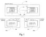
- FIG. 1is a block diagram presenting a configuration in which multiple networks each independently implement a Layer 2 redundancy protocol are connected to a common external network according to one embodiment of the present invention
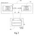
- FIG. 2is a block diagram presenting a customer spanning tree network connected to network devices maintained by an external network that are in a preforwarding state according to one embodiment of the present invention
- FIG. 3is a block diagram presenting a customer network and external network each implementing multiple spanning trees according to one embodiment of the present invention
- FIG. 4is a block diagram presenting a customer network implementing a plurality of spanning trees and a external network implementing a single spanning tree according to one embodiment of the present invention
- FIG. 5is a block diagram presenting a customer network implementing a single spanning tree and a external network implementing a plurality of spanning trees according to one embodiment of the present invention
- FIG. 6is a block diagram presenting a customer network implementing a single spanning tree and a external network implementing a single spanning tree according to one embodiment of the present invention
- FIG. 7is a block diagram presenting multiple interconnected networks, each instantiating one or more independent layer 2 redundancy protocols according to one embodiment of the present invention
- FIG. 8is a flow diagram presenting a method of configuring a external network device to operate according to one embodiment of the present invention.
- FIG. 9is a flow diagram presenting a method of operating various embodiments of the system of the present invention according to one embodiment of the present invention.
- Embodiments of a method, system, and article of manufacturecomprising software programs for instantiating a plurality of instances of a layer 2 (L2) redundancy protocol or protocols across multiple networks to ensure that each network topology is free of layer 2 loops in accordance with the present invention are described herein with reference to the drawings in FIGS. 1 through 9 .
- L2layer 2
- FIG. 1a network topology comprising hardware and software components configured according to one embodiment of the present invention is illustrated.
- the network topology presentedcomprises a number of network devices 102 , 104 , 106 and 108 performing layer 2 aggregation and switching functionality.
- each of these layer 2 devices 102 , 104 , 106 and 108may comprise hubs, switches, bridges or other network interconnection devices.
- each network deviceimplements one or more instances of a layer 2 redundancy protocol or protocols.
- network devices 102 , 104 , 106 and 108implement the spanning tree protocol, which continually provides a root device connected to a loop free layer 2 topology specifically in the event of a failure of the root device or any active layer 2 path in the topology.
- the network devicesmay implement other layer 2 redundancy protocols, such as the Metro Ring Protocol (MRP) or per-VLAN spanning tree plus protocol (PVST+).
- MRPMetro Ring Protocol
- PVST+per-VLAN spanning tree plus protocol
- each network device 106 and 108 in the external network 110further implements superspan protocol enhancements as provided by the present invention.
- the use of the superspan protocolallows both an external network 110 and one or more customer networks 100 a or 100 b to implement one or more instances of a layer 2 protocol or protocols without each implementation interfering with others.
- An exemplary Layer 2 device 102 , 104 , 106 and 108is the FastIron switch available from Foundry Networks of San Jose, Calif.
- Each customer network 100 a and 100 bcomprises one or more network devices 102 and 104 comprising a plurality of connections to network devices 106 and 108 that form part of an external network 110 .
- the connections to the external network 110provide each customer network 100 a and 100 b with routes to the external network 110 and other networks that the external network 110 is connected to, such as the Internet.
- each customer network 100 a and 100 bimplements one or more instances of a layer 2 redundancy protocol or protocols. As illustrated in FIG. 1 , it is common to construct Layer 2 networks with redundant connections to improve reliability.
- a network device 102 operating on customer network 100 amaintains two connections to the external network 110 , one connection to network device 106 via port 1 / 1 and one connection to network device 108 via port 1 / 2 . Where both ports are actively passing data packets, however, this redundancy can lead to broadcast storms with data packets looping throughout the network.
- a layer 2 redundancy protocolsuch as the spanning tree protocol, provides a mechanism for network devices, e.g., network devices 102 and 104 , to learn the network topology, elect a root bridge, and selectively block ports to thereby form a loop free topology.
- Two initial requirementmust be met by the network devices participating in the layer 2 redundancy protocol: (1) all network devices exchange information by way of control packets, e.g., Bridge Protocol Data Units (BPDUs), that are transmitted on all routes or ports maintained by the network device and (2) a single root network device be elected based on the exchange of the control packets.
- the root network deviceis selected on the basis that it has the lowest bridge identifier value, which is a combination of the network device's unique Media Access Controller (MAC) address and a priority value defined for the given network device.
- MACMedia Access Controller
- the root network device on each network 102 and 104propagates control packets on each of its ports at regular intervals; all other network devices have a root port that is the port with the least cost route to the root network device and is used for receiving control packets from the root network device.
- all network devices in the networkhave determined the configuration of their ports, e.g., blocking or forwarding, each network device only forwards data packets between the root port and the ports that are designated as bridge ports for each network segment to which they are attached. All other ports are blocked so as to prevent them from forwarding data packets, thereby preventing a Layer 2 loop.
- each customer network 100 a and 100 bimplements one or more instances of its own layer 2 redundancy protocol or protocols.
- the primary obstacle to implementing a plurality of instances of a layer 2 redundancy protocol or protocols in the architecture of FIG. 1is that there is no mechanism to restrict control packets intended for a first customer network 100 a from another customer network, e.g., customer network 100 b . That is, control packets generated by network devices comprising customer network 100 a are propagated over links to network devices 106 and 108 comprising the external network 110 without a mechanism to prevent these control packets from inappropriately being forwarded to another customer network 100 b .
- the present inventionovercomes these limitations by implementing so-called “superspan” enhancements to a given layer 2 redundancy protocol that allows distinct instances of the given protocol to be simultaneously implemented in both the external network 110 and customer networks 100 a and 100 b .
- superspan enhancementsmay be found in the Foundry BigIron® network switching devices implementing SuperSpanTM.
- the superspan enhancementuses the concept of “virtual hubs” and “spanning tree domains” to scale the layer 2 network, thereby allowing a single large layer 2 redundancy domain to be organized into a collection of small, easy-to-manage, and faster-converging domains.
- each layer 2 redundancy protocol instantiated in a given domain at a customer network 100 a and 100 bgenerates its own control packets, e.g., Bridge Protocol Data Units (BPDUs), which are used to by network devices 102 and 104 to decide which of its redundant interfaces providing a route to the external network 110 should be placed in active or blocking state for that domain.
- BPDUsBridge Protocol Data Units
- each network device 106 and 108 at the external network 110 that connects to a layer 2 redundancy domaine.g., a spanning tree instantiated at customer network 100 a
- Software 112 resident on each network device 106 and 108 at the external network 110 that connects to a layer 2 redundancy domainare configured to recognize their situation as a boundary between the external network 110 and the customer networks 100 a and 100 b .
- Network devices 106 and 108 at the boundaryare referred to as boundary devices, each device comprising boundary interfaces that connect to one or more customer networks.
- Boundary devices and their interfacespartition the control packets in one layer 2 redundancy domain from the other to thereby effectively decouple the layer 2 redundancy protocol implemented in one domain from the other domains, making each domain a self-contained network topology with its own layer 2 redundancy.
- the external network 110comprises two network devices 106 and 108 implementing superspan enhancements by way of a superspan software module 112 .
- Each network device 106 and 108 comprising the external network 110is symmetrically connected to two customer networks 100 a and 100 b , each customer network implementing its own instance of a layer 2 redundancy protocol.
- the superspan enhancementsprevent layer 2 loops in the traffic flow with each customer while at the same time isolating traffic to and from each customer network 102 and 104 .
- the network device 102 connecting customer network 100 a to the external network 110has two interfaces to the external network 110 , ports 1 / 1 and 1 / 2 .
- the external network devices 106 and 108 comprising the external network 110behave similar to a non-blocking hub whereby control packets from both customer networks 100 a and 100 b are tunneled through the external network 110 back to a given source network for the control packet.
- the customer network 102places port 1 / 2 into a blocking state.
- Network devices 106 and 108 on the external network 100execute a superspan software module 112 to tunnel packets and thereby route them back to a given origination network.
- the superspan software module 112utilizes a unique identifier to identify and ensure proper tunneling of control packets received at the external network 110 from customer networks 100 a and 100 b .
- the layer 2 redundancy protocol or protocols that the customer networks 100 a and 100 b implementdo not interfere with one another because the superspan software 112 executing at external network devices 106 and 108 isolate each network's control packets based on the unique identifier generated by network devices 102 and 104 comprising each customer network 100 a and 100 b and associated with a given network's control packets.
- the superspan software module 112changes the MAC address of the received control packet.
- the control packetsis a spanning tree BPDU and the superspan software module 112 modifies the MAC address of the received BPDU such that the first byte (locally administered bit) is changed from 01 to 03 to indicate that the BPDU needs to be tunneled between the boundary interfaces.
- the superspan software module 112modifies the fourth and fifth bytes to include the transmitting customer network's 100 a and 100 b unique identifier as specified on the boundary interface 106 and 108 .
- the superspan software module 112may modify the address to indicate the origination network of the control packet, e.g., customer network 100 a , thereby resulting in a modified MAC address of 03-08-c2-00-01-00 and preventing the control packet from being forwarded to a network other than the origination network.
- Each network device 106 and 108 in the external network 110 implementing the superspan enhancementsfloods the control packets through the external network using the modified destination MAC address.
- the superspan software module 112changes the destination MAC address back to the bridge group address to indicate to the customer network that identical traffic is appearing on two ports, thereby allowing the customer network to block one port and resolve the Layer 2 loop.
- This techniqueis referred to a “tunneling” as each customer network's control packets are flooded through the external network in a distinct tunnel based on the customer identifier for the customer network.
- control packets received from customer network 100 amay be received at network device 106 , flooded through the external network 110 and passed back through the boundary interface at network device 108 to the customer network 100 a .
- the control packetsare flooded through the external network 110 , there is a logical link 114 between the network devices 106 and 108 comprising the boundary interface.
- floodingmay comprise selectively forwarding packets throughout the network or selectively forwarding only toward interested recipients, e.g., through the use of GARP Multicast Registration Protocol (GMRP, wherein GARP stands for Generic Attribute Registration Protocol).
- GMRPGARP Multicast Registration Protocol
- FIG. 2builds on the embodiment introduced in FIG. 1 by illustrating the convergence of a one or more layer 2 redundancy protocols implemented at single customer network comprising symmetrical connections to network devices maintained by an external network.
- the superspan software module 210forces each external network device, e.g., network devices 204 and 206 , to enter a special state referred to as “preforwarding”, occurring between the learning and forwarding states, which lasts long enough to tolerate minimal control packet loss.
- preforwardingmay last 2H+1. If the hello timer is two seconds, the preforwarding state is entered into for a duration of five seconds.
- the external network devices 204 and 206During the preforwarding state, the external network devices 204 and 206 only forward tunneled control packets from the customer network 202 and prevent the forwarding of general data packet traffic. Forwarding only control packet traffic back to the customer network 202 ensures that the customer network 202 detects the layer 2 loop and blocks one or more ports within the customer network 202 , while the external network remains unblocked.
- the external network devices 204 and 206switch over to the forwarding state and continue to forward control packets in addition to general data packet traffic.
- the superspan software module 210must be enabled on at least the VLANs that are tunneling customer traffic.
- FIGS. 3 through 6present embodiments of the invention whereby various combinations of single and multiple layer 2 redundancy protocols are implemented on external and customer networks.
- FIG. 3an illustration of the superspan enhancements is presented wherein both the customer network 302 and the external network 310 implement multiple instances of a layer 2 redundancy protocol or protocols, e.g., a separate spanning tree in each port-based VLAN.
- both the customer network 302 and the external network 310are running multiple instances of a layer 2 redundancy protocol, one per port-based VLAN in a layer 2 switched network.
- the customer network 302comprises VLANs 10 ( 306 ) and 20 ( 308 ) while the external network comprises VLANs 100 ( 312 ) and 200 ( 314 ). Traffic from the customer network from VLANs 10 and 20 is aggregated by VLAN 100 at the external network because the boundary ports 312 and 314 are untagged members of VLAN 100 .
- the administrator of the customer networkmay select a different root bridge for each layer 2 redundancy protocol running on the customer network.
- the layer 2 redundancy protocol implemented in VLAN 10transmits control packets over the network 302 , which are passed to the external network.
- the control packetsare modified and flooded throughout network device 312 , 314 and 316 comprising the network 310 .
- Boundary interface network device 314receives the control packets and restores them to their original states, which are then passed back to the customer network 302 .
- network device 306is transitions to become the root bridge for the VLAN, thereby setting port 1 / 1 on network device 306 to forwarding while blocking port 3 / 1 on network device 308 .
- the opposite implementationoccurs for the layer 2 redundancy protocol implemented on VLAN 20 ( 308 ).
- both links 306 and 308 connecting the customer network 302 and the external network 310are fully utilized and serve as backup links at the same time, thereby providing a loop free, non-blocking topology.
- multiple instances of a layer 2 redundancy protocolare running, one for VLAN 100 ( 312 ) and one for VLAN 200 ( 314 ) to ensure a loop free, non-blocking topology is maintained for each VLAN.
- Boundary interfacesare configured at network devices 312 and 314 . Because traffic from the customer network 302 is aggregated into a single network device 312 , the external network 310 appears to the customer network 302 as a loop free non-blocking hub when port 2 / 2 on R 200 ( 314 ) is blocked by the layer 2 redundancy protocol operating in VLAN 100 ( 312 ). Furthermore, according to the present invention, boundary interfaces 2 / 1 ( 312 ) and 2 / 1 ( 314 ) do not transmit layer 2 redundancy protocol control packets generated at the external network out towards the customer network 302 .
- FIG. 4presents an alternative embodiment of the invention whereby the customer network 402 implements multiple instances of a layer 2 redundancy protocol while the external network 410 implements a single instance of a layer 2 redundancy protocol.
- an instance of a layer 2 redundancy protocolis implemented on each VLAN, identified by root network device 406 , which is the root network device for the layer 2 redundancy protocol implemented on VLAN 10 , and root network device 408 , which is the root network device for the layer 2 redundancy protocol implemented on VLAN 20 .
- the external network 410implements a single spanning tree with one root network device 416 .
- the external network 410is free to implement multiple VLANs at the network core to segregate traffic on a per customer basis. All VLANs, however, have the same network topology because the route for each VLAN is calculated by the single instance of a layer 2 redundancy protocol implementation, e.g., a single spanning tree ending at the root network device 416 for the spanning tree.
- the loop free, non-blocking network provided by the external network 410is treated as a hub by the customer network 402 , with boundary ports 2 / 1 on each boundary interface 414 and 416 being an untagged member of a common VLAN, e.g., VLAN 100 ; traffic from all VLANs maintained by the customer network is aggregated through the common VLAN at the boundary interface network devices.
- This configurationlaves the customer network's switching pattern virtually unchanged from the scenario presented in FIG. 3 as the external network 410 is perceived as a virtual hub by the customer network 402 , with maintenance of the virtual hub's loop free topology remaining transparent to the customer network 402 .
- FIG. 5A third embodiment of an architecture implementing the superspan enhancements is presented in FIG. 5 whereby the customer network 502 implements a single instance of a layer 2 redundancy protocol with a single root network device 508 , while the external network maintains multiple instances of a layer 2 redundancy protocol, identified by root network device 514 , which is the root network device for the layer 2 redundancy protocol implemented in VLAN 100 , and root network device 516 , which is the root network device for the layer 2 redundancy protocol implemented in VLAN 200 .
- root network device 514which is the root network device for the layer 2 redundancy protocol implemented in VLAN 100
- root network device 516which is the root network device for the layer 2 redundancy protocol implemented in VLAN 200 .
- Traffic from the VLANs maintained on the customer network 502all pass through the root network device 508 for the single implemented instance of a layer 2 redundancy protocol and are carried, or aggregated, at VLAN 100 maintained by external network device 516 at the boundary interface on the external network 510 .
- the main difference between the scenarios presented in FIG. 5 and those of FIGS. 3 and 4is that all traffic at the customer network 502 follows the same path, each path having the same layer 2 redundancy protocol root network device in all VLANs.
- Loop free, non-blocking topologiesare still separately maintained at the customer network 502 via a single instance of a layer 2 redundancy protocol and at the external network 510 via per-VLAN instances of a layer 2 redundancy protocol, VLAN 100 identified by root network device 516 and VLAN 200 identified by root network device 514 .
- both the customer network and the external networkimplement their own single instance of a layer 2 redundancy protocol in order to provide loop free, non-blocking Layer 2 topologies.
- Traffic from all VLANs maintained at the customer network 602is routed through the single layer 2 redundancy protocol's root network device 608 , which is carried, or aggregated, to the external network device 616 as in the previous scenario.
- Loop free, non-blocking topologiesare still separately maintained by a single instance of a layer 2 redundancy protocol on the customer network 602 and a single instance of a layer 2 redundancy protocol on the external network 610 .
- the superspan enhancements of the present inventionmay also operate in a “ladder” configuration as presented in FIG. 7 whereby a first network is an external network as to a first set of customer networks and a customer network as to a second external network, e.g., a network is both a customer network and an external network.
- Two customer networksare provided 700 a and 700 b , each comprising network devices implementing one or more instances of a layer 2 redundancy protocol or protocols, e.g., network devices 702 and 704 , respectively.
- the layer 2 network devices 702 and 704generate control packets as part of their implementation of the layer 2 redundancy protocol, which are propagated from the customer networks 700 a and 700 b to a first external network 706 .
- the control packetsare manipulated by the receiving network device 708 and 710 and flooded through the external network 706 .
- a network device 708 and 710that is configured as a boundary interface with a given client network 700 a and 700 b intercepts the flooded control packet based on the packet's destination and customer identification information.
- the intercepting network device 708 and 710reverts the data in the control packet to its original state and the control packet is passed back to the originating customer network 700 a and 700 b .
- control packets for various networks 700 a and 700 b connecting to the external network 706are advantageously isolated from one another, e.g., they are tunneled through the external network 706 based on their associated customer identifier, in addition to be isolated from control packets generated at the external network 706 .
- the external network 706It is also possible to implement one or more instances of a layer 2 redundancy protocol at the external network 706 . Because the external network 706 is attached to a core region, e.g., the external network 706 is a secondary core, the external network 706 appears as a customer network to the second external or core network 716 .
- Network devices 708 and 710 at the external network 706are configured with a unique customer identifier that is associated with control packets generated by the one or more layer 2 redundancy protocol or protocols that are implemented at the external network 706 .
- Superspan software 712 operating on each network device 708 and 710prevents the control packets from being propagated to the external network's 706 customer networks 700 a and 700 b.
- the control packetsare manipulated by the receiving network device 718 and 720 and flooded through the external network 716 .
- the network device 718 and 720that is configured as a boundary interface with a given client network 706 intercepts the flooded control packets based on the packet's destination and customer identification information.
- the intercepting network device 718 and 720reverts the data in the control packet to its original state and the control packet is passed back to the originating customer network 706 .
- control packets for various networks connecting to the external network 716are advantageously isolated from one another, e.g., they are tunneled through the external network 716 based on their associated customer identifier.
- each region 700 a and 700 b , 706 and 716is assigned a priority or customer identifier (CID) value that is associated with control packets generated by any given layer 2 redundancy protocol implemented in one of the networks 700 a and 700 b , 706 and 716700 a and 700 b , 706 and 716 .
- the core network 716tunnels control packets from the edge 700 a and 700 b through the secondary core 706 .
- progressively higher CID valuesare assigned to the interfaces between the networks 722 and 724 .
- control packetscomprising non-matching CID values—non-matching in that the CID carried by the received control packet does not match the CID for the receiving boundary port—where (CID control packet >CID boundary ) are propagated through the receiving network unchanged
- FIG. 8One embodiment of a method for configuring network devices comprising the external network is presented in FIG. 8 .
- a network device administrator at the external networkconfigures superspan software resident on all devices in the same broadcast domain in the external network that are connected to a customer network, step 802 .
- Superspan softwaremay comprise program code stored in an EEPROM or any other suitable memory media that may be accessed by the external network device in order to execute the program code contained therein and execute methods of the present invention.
- the administratordefines the unique customer identifiers that represent customer networks to which each boundary interface connects, step 804 .
- the same unique identifieris defined at each boundary interface that connects to a given customer network.
- the network devicesuse the identifier to ensure that control packets are forwarded only to the intended customer network.
- the superspan softwareis enabled, step 806 , allowing the network device to enter preforwarding mode thereby indicating to a connected customer network that a loop is present and a selected port must be set to blocking mode.
- Exemplary commands for configuring one of the two boundary interfaces presented in FIG. 1are introduced in Table 1 below. These commands may be supplied via a command line or other interface provided by the superspan software or other operating software executing on the network device. Alternatively, an administrator may execute commands through the use of one or more scripts as is well known to those of skill in the art.
- Interface 1/1 stp-boundary 1 interface 1/2 stp-boundary 2These commands configure two interfaces on the network device as superspan boundaries.
- Interface 1 / 1is a boundary interface for a first customer whereas interface 1 / 2 is a boundary interface with a second customer.
- Each boundaryis associated with a unique number that identifies the customer network for which the network device is acting as a boundary interface.
- the unique identifiermay be a more complex alpha or alphanumeric character or characters.
- Each customeris allocated a unique identifier used at every boundary interface to identify and distinguish each customer's control packets.
- FIG. 9One embodiment of a method for operating embodiments of the systems presented in FIGS. 1 through 7 is presented in FIG. 9 .
- a customer networkis initialized and all Layer 2 devices cycle their power or are otherwise initialized from a non-initialized state, step 902 , thereby initiating the layer 2 redundancy protocol that the layer 2 devices support.
- All network devices comprising the external networkincluding those boundary interface network devices that comprise a connection to a customer network, initialize their superspan software as previously described in order for the external network to appear as a single non-blocking virtual hub, step 904 .
- the network devices that form the boundary interface for the given customerenter preforwarding mode, step 906 , whereby control packets are received at one port of the interface, tunneled through the network devices comprising the external network, and transmitted back to the customer network across other connections between the customer network and the boundary interface, thereby alerting the customer network to a loop, step 908 .
- the control packet propagation of step 908is conducted for each customer network attached to the external network whereby each customer network's control packets are isolated from each other via a unique identifier that is associated with each control packet that a customer network generates.
- network devices in the customer networkenter a converges; ports are selectively blocked in order to prevent loops in the topology, step 910 .
- thisallows multiple customers that share a boundary interface with an external network to each implement one or more instances of a layer 2 redundancy protocol or protocols for loop avoidance while not interfering with the other.
Landscapes
- Engineering & Computer Science (AREA)
- Computer Networks & Wireless Communication (AREA)
- Signal Processing (AREA)
- Data Exchanges In Wide-Area Networks (AREA)
Abstract
Description
| TABLE 1 | ||
| stp- | ||
| stp- | ||
These commands configure two interfaces on the network device as superspan boundaries.
Claims (13)
Priority Applications (2)
| Application Number | Priority Date | Filing Date | Title |
|---|---|---|---|
| US10/261,946US8462668B2 (en) | 2002-10-01 | 2002-10-01 | System and method for implementation of layer 2 redundancy protocols across multiple networks |
| US13/893,111US9391888B2 (en) | 2002-10-01 | 2013-05-13 | System and method for implementation of layer 2 redundancy protocols across multiple networks |
Applications Claiming Priority (1)
| Application Number | Priority Date | Filing Date | Title |
|---|---|---|---|
| US10/261,946US8462668B2 (en) | 2002-10-01 | 2002-10-01 | System and method for implementation of layer 2 redundancy protocols across multiple networks |
Related Child Applications (1)
| Application Number | Title | Priority Date | Filing Date |
|---|---|---|---|
| US13/893,111ContinuationUS9391888B2 (en) | 2002-10-01 | 2013-05-13 | System and method for implementation of layer 2 redundancy protocols across multiple networks |
Publications (2)
| Publication Number | Publication Date |
|---|---|
| US20090274153A1 US20090274153A1 (en) | 2009-11-05 |
| US8462668B2true US8462668B2 (en) | 2013-06-11 |
Family
ID=41257039
Family Applications (2)
| Application Number | Title | Priority Date | Filing Date |
|---|---|---|---|
| US10/261,946Expired - Fee RelatedUS8462668B2 (en) | 2002-10-01 | 2002-10-01 | System and method for implementation of layer 2 redundancy protocols across multiple networks |
| US13/893,111Expired - Fee RelatedUS9391888B2 (en) | 2002-10-01 | 2013-05-13 | System and method for implementation of layer 2 redundancy protocols across multiple networks |
Family Applications After (1)
| Application Number | Title | Priority Date | Filing Date |
|---|---|---|---|
| US13/893,111Expired - Fee RelatedUS9391888B2 (en) | 2002-10-01 | 2013-05-13 | System and method for implementation of layer 2 redundancy protocols across multiple networks |
Country Status (1)
| Country | Link |
|---|---|
| US (2) | US8462668B2 (en) |
Cited By (6)
| Publication number | Priority date | Publication date | Assignee | Title |
|---|---|---|---|---|
| US20060007869A1 (en)* | 2004-07-09 | 2006-01-12 | Fujitsu Limited | Method for preventing control packet loop and bridge apparatus using the method |
| US20120076151A1 (en)* | 2002-10-29 | 2012-03-29 | Finn Norman W | Multi-Bridge LAN Aggregation |
| US20130250815A1 (en)* | 2012-03-22 | 2013-09-26 | Fujitsu Limited | Distributed spanning tree protocol |
| US9450893B2 (en) | 2002-04-16 | 2016-09-20 | Brocade Communications Systems, Inc. | System and method for providing network route redundancy across layer 2 devices |
| CN106713084A (en)* | 2016-12-01 | 2017-05-24 | 上海雍敏信息科技有限公司 | multi-gateway system of Internet of Things |
| US11791120B2 (en) | 2021-05-21 | 2023-10-17 | G&W Electric Company | Status indicator for switchgear |
Families Citing this family (36)
| Publication number | Priority date | Publication date | Assignee | Title |
|---|---|---|---|---|
| US8462668B2 (en) | 2002-10-01 | 2013-06-11 | Foundry Networks, Llc | System and method for implementation of layer 2 redundancy protocols across multiple networks |
| US7379429B1 (en)* | 2002-12-20 | 2008-05-27 | Foundry Networks, Inc. | Optimizations and enhancements to the IEEE RSTP 802.1w implementation |
| US7627654B2 (en)* | 2003-06-09 | 2009-12-01 | Foundry Networks, Inc. | System and method for multiple spanning tree protocol domains in a virtual local area network |
| JP4704120B2 (en)* | 2005-06-13 | 2011-06-15 | 富士通株式会社 | Network failure detection apparatus and network failure detection method |
| US7835378B2 (en)* | 2006-02-02 | 2010-11-16 | Cisco Technology, Inc. | Root node redundancy for multipoint-to-multipoint transport trees |
| US8391185B2 (en)* | 2007-05-29 | 2013-03-05 | Cisco Technology, Inc. | Method to transport bidir PIM over a multiprotocol label switched network |
| US7864712B2 (en)* | 2007-07-20 | 2011-01-04 | Cisco Technology, Inc. | Preventing loops in networks operating different protocols to provide loop-free topology |
| US7936754B2 (en)* | 2008-12-12 | 2011-05-03 | At&T Intellectual Property I, L.P. | Methods and apparatus to dynamically store network routes for a communication network |
| US8538919B1 (en)* | 2009-05-16 | 2013-09-17 | Eric H. Nielsen | System, method, and computer program for real time remote recovery of virtual computing machines |
| US9270487B1 (en)* | 2009-10-13 | 2016-02-23 | Teradata Us, Inc. | Full bisection bandwidth network |
| US8428062B2 (en)* | 2010-02-16 | 2013-04-23 | Juniper Networks, Inc. | Network provider bridge MMRP registration snooping |
| US8654630B2 (en) | 2010-03-19 | 2014-02-18 | Brocade Communications Systems, Inc. | Techniques for link redundancy in layer 2 networks |
| US8774010B2 (en) | 2010-11-02 | 2014-07-08 | Cisco Technology, Inc. | System and method for providing proactive fault monitoring in a network environment |
| US8559341B2 (en)* | 2010-11-08 | 2013-10-15 | Cisco Technology, Inc. | System and method for providing a loop free topology in a network environment |
| US8982733B2 (en) | 2011-03-04 | 2015-03-17 | Cisco Technology, Inc. | System and method for managing topology changes in a network environment |
| US8687649B2 (en)* | 2011-03-08 | 2014-04-01 | International Business Machines Corporation | Message forwarding toward a source end node in a converged network environment |
| US8842684B2 (en) | 2011-03-10 | 2014-09-23 | Extreme Networks, Inc. | Forwarding inter-switch connection (ISC) frames in a network-to-network interconnect topology |
| US8670326B1 (en) | 2011-03-31 | 2014-03-11 | Cisco Technology, Inc. | System and method for probing multiple paths in a network environment |
| US8724517B1 (en) | 2011-06-02 | 2014-05-13 | Cisco Technology, Inc. | System and method for managing network traffic disruption |
| CN102821033B (en)* | 2011-06-10 | 2017-04-12 | 中兴通讯股份有限公司 | Message transmission method and device |
| US8830875B1 (en) | 2011-06-15 | 2014-09-09 | Cisco Technology, Inc. | System and method for providing a loop free topology in a network environment |
| JP5821815B2 (en)* | 2012-09-11 | 2015-11-24 | 日立金属株式会社 | Communication system and communication system processing method |
| US9450846B1 (en) | 2012-10-17 | 2016-09-20 | Cisco Technology, Inc. | System and method for tracking packets in a network environment |
| US9450891B2 (en)* | 2013-02-20 | 2016-09-20 | Marvell World Trade Ltd. | System and method for enabling G.HN nodes to support 1905.1 relaying (MAC relaying) while supporting legacy G.HN relaying according to the G.HN standards |
| US10009371B2 (en)* | 2013-08-09 | 2018-06-26 | Nicira Inc. | Method and system for managing network storm |
| US9729432B2 (en)* | 2015-11-25 | 2017-08-08 | Cisco Technology, Inc. | Different forwarding of packets based on whether received from a core or customer network |
| US10812289B2 (en)* | 2016-03-18 | 2020-10-20 | Hewlett Packard Enterprise Development Lp | Responses to loops in networks having a ring topology |
| US11689455B2 (en) | 2020-05-28 | 2023-06-27 | Oracle International Corporation | Loop prevention in virtual layer 2 networks |
| US11876708B2 (en) | 2020-07-14 | 2024-01-16 | Oracle International Corporation | Interface-based ACLs in a layer-2 network |
| US11552821B2 (en)* | 2020-12-15 | 2023-01-10 | Arista Networks, Inc. | Spanning tree protocol with ethernet virtual private network all-active multihoming |
| US11909636B2 (en) | 2020-12-30 | 2024-02-20 | Oracle International Corporation | Layer-2 networking using access control lists in a virtualized cloud environment |
| EP4272379B1 (en) | 2020-12-30 | 2024-10-02 | Oracle International Corporation | Layer-2 networking using access control lists in a virtualized cloud environment |
| US11671355B2 (en) | 2021-02-05 | 2023-06-06 | Oracle International Corporation | Packet flow control in a header of a packet |
| WO2022173552A1 (en) | 2021-02-13 | 2022-08-18 | Oracle International Corporation | Cloud infrastructure resources for connecting a service provider private network to a customer private network |
| US11777897B2 (en) | 2021-02-13 | 2023-10-03 | Oracle International Corporation | Cloud infrastructure resources for connecting a service provider private network to a customer private network |
| US20240146641A1 (en)* | 2022-10-26 | 2024-05-02 | Schweitzer Engineering Laboratories, Inc. | Communication device operable under multiple control planes |
Citations (40)
| Publication number | Priority date | Publication date | Assignee | Title |
|---|---|---|---|---|
| US5473599A (en) | 1994-04-22 | 1995-12-05 | Cisco Systems, Incorporated | Standby router protocol |
| US6032194A (en) | 1997-12-24 | 2000-02-29 | Cisco Technology, Inc. | Method and apparatus for rapidly reconfiguring computer networks |
| US6285656B1 (en) | 1999-08-13 | 2001-09-04 | Holontech Corporation | Active-passive flow switch failover technology |
| US6304575B1 (en) | 1998-08-31 | 2001-10-16 | Cisco Technology, Inc. | Token ring spanning tree protocol |
| US6373826B1 (en) | 1998-12-15 | 2002-04-16 | Nortel Networks Limited | Spanning tree algorithm |
| US6397260B1 (en) | 1999-03-08 | 2002-05-28 | 3Com Corporation | Automatic load sharing for network routers |
| US6470395B1 (en)* | 1998-10-21 | 2002-10-22 | Alcatel | Method to impose execution of a predefined command, first terminal and second terminal realizing such a method and a communication network including such a first terminal and such a second terminal |
| US20020184376A1 (en) | 2001-05-30 | 2002-12-05 | Sternagle Richard Henry | Scalable, reliable session initiation protocol (SIP) signaling routing node |
| US6493825B1 (en) | 1998-06-29 | 2002-12-10 | Emc Corporation | Authentication of a host processor requesting service in a data processing network |
| US6501756B1 (en) | 1998-06-30 | 2002-12-31 | Kabushiki Kaisha Toshiba | Method of managing hop-count in label switching network and node apparatus |
| US20030037165A1 (en) | 2001-07-06 | 2003-02-20 | Daisuke Shinomiya | Dynamic load sharing system using a virtual router |
| US20030048746A1 (en) | 2001-09-12 | 2003-03-13 | Michael Guess | Metropolitan area local access service system |
| US6535490B1 (en) | 1999-03-04 | 2003-03-18 | 3Com Corporation | High availability spanning tree with rapid reconfiguration with alternate port selection |
| US6556541B1 (en)* | 1999-01-11 | 2003-04-29 | Hewlett-Packard Development Company, L.P. | MAC address learning and propagation in load balancing switch protocols |
| US20030086422A1 (en)* | 2001-11-02 | 2003-05-08 | Netvmg, Inc. | System and method to provide routing control of information over networks |
| US20030193959A1 (en)* | 2002-01-20 | 2003-10-16 | General Instrument Corporation | Method and apparatus for priority-based load balancing for use in an extended local area network |
| US20030225908A1 (en)* | 2002-06-04 | 2003-12-04 | Shriram Srinivasan | Loop elimination in a communications network |
| US6717922B2 (en) | 2002-03-04 | 2004-04-06 | Foundry Networks, Inc. | Network configuration protocol and method for rapid traffic recovery and loop avoidance in ring topologies |
| US6728777B1 (en)* | 1999-06-02 | 2004-04-27 | Nortel Networks Limited | Method for engineering paths for multicast traffic |
| US6766482B1 (en) | 2001-10-31 | 2004-07-20 | Extreme Networks | Ethernet automatic protection switching |
| US6813250B1 (en)* | 1997-12-23 | 2004-11-02 | Cisco Technology, Inc. | Shared spanning tree protocol |
| US6839348B2 (en)* | 1999-04-30 | 2005-01-04 | Cisco Technology, Inc. | System and method for distributing multicasts in virtual local area networks |
| US6850531B1 (en) | 1999-02-23 | 2005-02-01 | Alcatel | Multi-service network switch |
| US6856591B1 (en) | 2000-12-15 | 2005-02-15 | Cisco Technology, Inc. | Method and system for high reliability cluster management |
| US6879594B1 (en)* | 1999-06-07 | 2005-04-12 | Nortel Networks Limited | System and method for loop avoidance in multi-protocol label switching |
| US6891808B2 (en) | 2000-03-10 | 2005-05-10 | Anritsu Corporation | Spanning tree bridge and route change method using the same |
| US6952397B2 (en) | 2001-06-07 | 2005-10-04 | Corrigent Systems Ltd. | Communication in a bidirectional ring network with single-direction receiving |
| US6954436B1 (en) | 2001-02-28 | 2005-10-11 | Extreme Networks, Inc. | Method and apparatus for selecting redundant routers using tracking |
| US6987740B1 (en)* | 2000-09-11 | 2006-01-17 | Cisco Technology, Inc. | STP root guard |
| US7027406B1 (en) | 1998-04-16 | 2006-04-11 | Avaya Communication Israel Ltd. | Distributed port-blocking method |
| US7126923B1 (en)* | 2002-05-28 | 2006-10-24 | Extreme Networks, Inc. | Method and system for inter-domain loop protection using a hierarchy of loop resolving protocols |
| US7154861B1 (en) | 2002-04-22 | 2006-12-26 | Extreme Networks | Method and system for a virtual local area network to span multiple loop free network topology domains |
| US20070008942A1 (en)* | 2002-09-11 | 2007-01-11 | Ocepek Steven R | Security apparatus and method for local area networks |
| US7209435B1 (en) | 2002-04-16 | 2007-04-24 | Foundry Networks, Inc. | System and method for providing network route redundancy across Layer 2 devices |
| US7289496B2 (en) | 2001-12-22 | 2007-10-30 | 3Com Corporation | Cascade system for network units |
| US7340535B1 (en) | 2002-06-04 | 2008-03-04 | Fortinet, Inc. | System and method for controlling routing in a virtual router system |
| US7359984B1 (en)* | 2002-07-15 | 2008-04-15 | Packeteer, Inc. | Management of network quality of service |
| US7389359B2 (en) | 2001-10-19 | 2008-06-17 | Foundry Networks, Inc. | Method and system for intelligently forwarding multicast packets |
| US7389496B2 (en) | 2003-07-02 | 2008-06-17 | Agere Systems Inc. | Condition management system and a method of operation thereof |
| US20090003213A1 (en) | 2000-11-14 | 2009-01-01 | Broadcom Corporation | Linked network switch configuration |
Family Cites Families (27)
| Publication number | Priority date | Publication date | Assignee | Title |
|---|---|---|---|---|
| US5920566A (en)* | 1997-06-30 | 1999-07-06 | Sun Microsystems, Inc. | Routing in a multi-layer distributed network element |
| US6014380A (en)* | 1997-06-30 | 2000-01-11 | Sun Microsystems, Inc. | Mechanism for packet field replacement in a multi-layer distributed network element |
| US6366557B1 (en) | 1997-10-31 | 2002-04-02 | Nortel Networks Limited | Method and apparatus for a Gigabit Ethernet MAC (GMAC) |
| US6826616B2 (en) | 1998-10-30 | 2004-11-30 | Science Applications International Corp. | Method for establishing secure communication link between computers of virtual private network |
| US6631134B1 (en) | 1999-01-15 | 2003-10-07 | Cisco Technology, Inc. | Method for allocating bandwidth in an optical network |
| CA2261323A1 (en) | 1999-02-05 | 2000-08-05 | Newbridge Networks Corporation | Backup procedure for dss2-based signalling links |
| US6788681B1 (en)* | 1999-03-16 | 2004-09-07 | Nortel Networks Limited | Virtual private networks and methods for their operation |
| US6934795B2 (en) | 1999-09-23 | 2005-08-23 | Netlogic Microsystems, Inc. | Content addressable memory with programmable word width and programmable priority |
| CA2393451C (en) | 1999-12-10 | 2010-05-25 | Diva Systems Corporation | Method and apparatus of load sharing and improving fault tolerance in an interactive video distribution system |
| US7463581B1 (en) | 2000-02-07 | 2008-12-09 | Cisco Technology, Inc. | Re-routing connections using redundant path connections and loopbacks |
| EP1316017A2 (en) | 2000-08-07 | 2003-06-04 | Inrange Technologies Corporation | Method and apparatus for imparting fault tolerance in a director switch |
| US7072303B2 (en) | 2000-12-11 | 2006-07-04 | Acme Packet, Inc. | System and method for assisting in controlling real-time transport protocol flow through multiple networks |
| US7130303B2 (en) | 2001-03-15 | 2006-10-31 | Lucent Technologies Inc. | Ethernet packet encapsulation for metropolitan area ethernet networks |
| US7065041B2 (en) | 2001-12-14 | 2006-06-20 | Siemens Communications, Inc. | Method for resilient call setup through ATM networks for Softswitch applications |
| US7319664B2 (en) | 2002-01-10 | 2008-01-15 | Accton Technology Corporation | Redundant link management switch for use in a stack of switches and method thereof |
| US7161935B2 (en) | 2002-01-31 | 2007-01-09 | Brocade Communications Stystems, Inc. | Network fabric management via adjunct processor inter-fabric service link |
| US20030174725A1 (en) | 2002-03-15 | 2003-09-18 | Broadcom Corporation | IP multicast packet replication process and apparatus therefore |
| US7269135B2 (en) | 2002-04-04 | 2007-09-11 | Extreme Networks, Inc. | Methods and systems for providing redundant connectivity across a network using a tunneling protocol |
| US8462668B2 (en) | 2002-10-01 | 2013-06-11 | Foundry Networks, Llc | System and method for implementation of layer 2 redundancy protocols across multiple networks |
| US7428214B2 (en) | 2004-03-04 | 2008-09-23 | Cisco Technology, Inc. | Methods and devices for high network availability |
| US7603480B2 (en) | 2004-09-16 | 2009-10-13 | Nec Corporation | System using pseudo redundant configurator to switch network devices between operating and standby states |
| KR100603599B1 (en) | 2004-11-25 | 2006-07-24 | 한국전자통신연구원 | Redundancy control device of redundant switch board and its method |
| JP4461175B2 (en) | 2005-03-31 | 2010-05-12 | 富士通株式会社 | Transmission apparatus and redundancy method between transmission apparatus and layer 2 switch |
| US8400912B2 (en) | 2007-06-27 | 2013-03-19 | World Wide Packets, Inc. | Activating a tunnel upon receiving a control packet |
| US7751329B2 (en) | 2007-10-03 | 2010-07-06 | Avaya Inc. | Providing an abstraction layer in a cluster switch that includes plural switches |
| US8107360B2 (en) | 2009-03-23 | 2012-01-31 | International Business Machines Corporation | Dynamic addition of redundant network in distributed system communications |
| US8654630B2 (en) | 2010-03-19 | 2014-02-18 | Brocade Communications Systems, Inc. | Techniques for link redundancy in layer 2 networks |
- 2002
- 2002-10-01USUS10/261,946patent/US8462668B2/ennot_activeExpired - Fee Related
- 2013
- 2013-05-13USUS13/893,111patent/US9391888B2/ennot_activeExpired - Fee Related
Patent Citations (47)
| Publication number | Priority date | Publication date | Assignee | Title |
|---|---|---|---|---|
| US5473599A (en) | 1994-04-22 | 1995-12-05 | Cisco Systems, Incorporated | Standby router protocol |
| US6813250B1 (en)* | 1997-12-23 | 2004-11-02 | Cisco Technology, Inc. | Shared spanning tree protocol |
| US6032194A (en) | 1997-12-24 | 2000-02-29 | Cisco Technology, Inc. | Method and apparatus for rapidly reconfiguring computer networks |
| US7027406B1 (en) | 1998-04-16 | 2006-04-11 | Avaya Communication Israel Ltd. | Distributed port-blocking method |
| US6493825B1 (en) | 1998-06-29 | 2002-12-10 | Emc Corporation | Authentication of a host processor requesting service in a data processing network |
| US6501756B1 (en) | 1998-06-30 | 2002-12-31 | Kabushiki Kaisha Toshiba | Method of managing hop-count in label switching network and node apparatus |
| US6304575B1 (en) | 1998-08-31 | 2001-10-16 | Cisco Technology, Inc. | Token ring spanning tree protocol |
| US6470395B1 (en)* | 1998-10-21 | 2002-10-22 | Alcatel | Method to impose execution of a predefined command, first terminal and second terminal realizing such a method and a communication network including such a first terminal and such a second terminal |
| US6373826B1 (en) | 1998-12-15 | 2002-04-16 | Nortel Networks Limited | Spanning tree algorithm |
| US6556541B1 (en)* | 1999-01-11 | 2003-04-29 | Hewlett-Packard Development Company, L.P. | MAC address learning and propagation in load balancing switch protocols |
| US20030179707A1 (en)* | 1999-01-11 | 2003-09-25 | Bare Ballard C. | MAC address learning and propagation in load balancing switch protocols |
| US6850531B1 (en) | 1999-02-23 | 2005-02-01 | Alcatel | Multi-service network switch |
| US6535490B1 (en) | 1999-03-04 | 2003-03-18 | 3Com Corporation | High availability spanning tree with rapid reconfiguration with alternate port selection |
| US6397260B1 (en) | 1999-03-08 | 2002-05-28 | 3Com Corporation | Automatic load sharing for network routers |
| US6839348B2 (en)* | 1999-04-30 | 2005-01-04 | Cisco Technology, Inc. | System and method for distributing multicasts in virtual local area networks |
| US6728777B1 (en)* | 1999-06-02 | 2004-04-27 | Nortel Networks Limited | Method for engineering paths for multicast traffic |
| US6879594B1 (en)* | 1999-06-07 | 2005-04-12 | Nortel Networks Limited | System and method for loop avoidance in multi-protocol label switching |
| US6285656B1 (en) | 1999-08-13 | 2001-09-04 | Holontech Corporation | Active-passive flow switch failover technology |
| US6891808B2 (en) | 2000-03-10 | 2005-05-10 | Anritsu Corporation | Spanning tree bridge and route change method using the same |
| US20060092862A1 (en)* | 2000-09-11 | 2006-05-04 | Benedetto Marco D | STP root guard |
| US6987740B1 (en)* | 2000-09-11 | 2006-01-17 | Cisco Technology, Inc. | STP root guard |
| US20090003213A1 (en) | 2000-11-14 | 2009-01-01 | Broadcom Corporation | Linked network switch configuration |
| US6856591B1 (en) | 2000-12-15 | 2005-02-15 | Cisco Technology, Inc. | Method and system for high reliability cluster management |
| US6954436B1 (en) | 2001-02-28 | 2005-10-11 | Extreme Networks, Inc. | Method and apparatus for selecting redundant routers using tracking |
| US20020184376A1 (en) | 2001-05-30 | 2002-12-05 | Sternagle Richard Henry | Scalable, reliable session initiation protocol (SIP) signaling routing node |
| US6952397B2 (en) | 2001-06-07 | 2005-10-04 | Corrigent Systems Ltd. | Communication in a bidirectional ring network with single-direction receiving |
| US20030037165A1 (en) | 2001-07-06 | 2003-02-20 | Daisuke Shinomiya | Dynamic load sharing system using a virtual router |
| US20030048501A1 (en) | 2001-09-12 | 2003-03-13 | Michael Guess | Metropolitan area local access service system |
| US20030048746A1 (en) | 2001-09-12 | 2003-03-13 | Michael Guess | Metropolitan area local access service system |
| US7389359B2 (en) | 2001-10-19 | 2008-06-17 | Foundry Networks, Inc. | Method and system for intelligently forwarding multicast packets |
| US6766482B1 (en) | 2001-10-31 | 2004-07-20 | Extreme Networks | Ethernet automatic protection switching |
| US7003705B1 (en) | 2001-10-31 | 2006-02-21 | Extreme Networks, Inc. | Ethernet automatic protection switching |
| US20030086422A1 (en)* | 2001-11-02 | 2003-05-08 | Netvmg, Inc. | System and method to provide routing control of information over networks |
| US7289496B2 (en) | 2001-12-22 | 2007-10-30 | 3Com Corporation | Cascade system for network units |
| US20030193959A1 (en)* | 2002-01-20 | 2003-10-16 | General Instrument Corporation | Method and apparatus for priority-based load balancing for use in an extended local area network |
| US6717922B2 (en) | 2002-03-04 | 2004-04-06 | Foundry Networks, Inc. | Network configuration protocol and method for rapid traffic recovery and loop avoidance in ring topologies |
| US8014301B2 (en) | 2002-04-16 | 2011-09-06 | Brocade Communications Systems, Inc. | System and method for providing network route redundancy across layer 2 devices |
| US7209435B1 (en) | 2002-04-16 | 2007-04-24 | Foundry Networks, Inc. | System and method for providing network route redundancy across Layer 2 devices |
| US7558195B1 (en) | 2002-04-16 | 2009-07-07 | Foundry Networks, Inc. | System and method for providing network route redundancy across layer 2 devices |
| US20090296565A1 (en) | 2002-04-16 | 2009-12-03 | Foundry Networks, Inc. | System and method for providing network route redundancy across layer 2 devices |
| US7154861B1 (en) | 2002-04-22 | 2006-12-26 | Extreme Networks | Method and system for a virtual local area network to span multiple loop free network topology domains |
| US7126923B1 (en)* | 2002-05-28 | 2006-10-24 | Extreme Networks, Inc. | Method and system for inter-domain loop protection using a hierarchy of loop resolving protocols |
| US7340535B1 (en) | 2002-06-04 | 2008-03-04 | Fortinet, Inc. | System and method for controlling routing in a virtual router system |
| US20030225908A1 (en)* | 2002-06-04 | 2003-12-04 | Shriram Srinivasan | Loop elimination in a communications network |
| US7359984B1 (en)* | 2002-07-15 | 2008-04-15 | Packeteer, Inc. | Management of network quality of service |
| US20070008942A1 (en)* | 2002-09-11 | 2007-01-11 | Ocepek Steven R | Security apparatus and method for local area networks |
| US7389496B2 (en) | 2003-07-02 | 2008-06-17 | Agere Systems Inc. | Condition management system and a method of operation thereof |
Non-Patent Citations (108)
| Title |
|---|
| "BlackDiamond 6800 Series Switch Hardware Installation Guide," Extreme Networks, Apr. 201, 93 pages. |
| "Functional Description: Health Check/Fabric Checksum," printed on Feb. 12, 2002, available at http://www.extremenetworks.com/services/HealthCheck.aspx (5 pages). |
| Brocade Communication Systems, Inc. v. A10 Networks, Inc., Civil Action 10-332-Civil Cover Sheet, filed on Apr. 23, 2010, 1 page. |
| Brocade Communication Systems, Inc. v. A10 Networks, Inc., Civil Action 10-332-Complaint for Patent Infringement, filed on Apr. 23, 2010, 14 pages. |
| Brocade Communication Systems, Inc. v. A10 Networks, Inc., Civil Action 10-332-Exhibit A to the Complaint (U.S. Patent No. 7,558,195 B1, issued on Jul. 7, 2009, Kuo et al.), 29 pages. |
| Brocade Communication Systems, Inc. v. A10 Networks, Inc., Civil Action 10-332-Exhibit B to the Complaint (U.S. Patent No. 7,581,009 B1, issued on Aug. 25, 2009, Hsu et al.), 15 pages. |
| Brocade Communication Systems, Inc. v. A10 Networks, Inc., Civil Action 10-332-Exhibit C to the Complaint (U.S. Patent No. 7,454,500 B1, issued on Nov. 18, 2008, Hsu et al.), 12 pages. |
| Brocade Communication Systems, Inc. v. A10 Networks, Inc., Civil Action 10-332-Exhibit D to the Complaint (U.S. Patent No. 7,574,508 B1, issued on Aug. 11, 2009, Kommula), 15 pages. |
| Brocade Communication Systems, Inc. v. A10 Networks, Inc., Civil Action 10-332-Exhibit E to the Complaint (U.S. 7,647,427 B1, issued on Jan. 12, 2010, Devarapalli), 10 pages. |
| Brocade Communication Systems, Inc. v. A10 Networks, Inc., Civil Action 10-332-Exhibit F to the Complaint (U.S. 7,657,629 B1, issued on Feb. 2, 2010, Kommula), 20 pages. |
| Brocade Communication Systems, Inc. v. A10 Networks, Inc., Civil Action 10-332-Exhibit G to the Complaint (U.S. 7,584,301 B1, issued on Sep. 1, 2009, Joshi), 16 pages. |
| Chakraborty et al, "Improvement in Reliability of the Token Ring Network by Reversal of Token in Case of a Single Component Failure". IEEE. 1993. pp. 1152-1154. |
| Cisco Systems Inc., "Understanding Spanning-Tree Protocol," 8 pages, Copyright 1989-1997. |
| Civil Action 10-332-Notice of Voluntary Dismissal Without Prejudice, filed on Aug. 5, 2010, 2 pages. |
| Civil Action 10-332-Report on the Filing or Determination of an Action Regarding a Patent or Trademark, filed on Aug. 5, 2010, 2 pages. |
| Civil Action 10-332-Second Amended and Supplemental Complaint for Patent Infringement, filed on Jul. 16, 2010, with Exhibits A through I, 158 pages. |
| Civil Action CV10-03428-A10 Networks, Inc.'s Answer to Plaintiffs Brocade Communications Systems, Inc. and Foundry Networks, LLC's Counterclaims, Filed Jun. 17, 2011, 4 pages. |
| Civil Action CV10-03428-A10 Networks, Inc.'s, Lee Chen's, Rajkumar Jalan's, Ron Szeto's, Liang Han's, and Steve Hwang's Answer to Third Amended Complaint, Affirmative Defenses, and A10's Counterclaims, Filed May 16, 2011, 40 pages. |
| Civil Action CV10-03428-Administrative Motion to Consider Whether Cases Should be Related, filed by Brocade Communications Systems, Inc., Foundry Networks, LLC, filed Nov. 21, 2011, 8 pages, including Declaration and Proposed Order. |
| Civil Action CV10-03428-Administrative Motion to File Under Seal Brocade Communications Systems, Inc. and Foundry Networks, LLC's Administrative Motion for Leave to File Under Seal Notice of Errata and Submission of Corrected Brief filed by Brocade Communications Systems, Inc., Foundry Networks, LLC, filed Oct. 13, 2011, 8 pages including Proposed Order and Declaration. |
| Civil Action CV10-03428-Declaration of Andrew (Andy) Guerrero in Support of Motion for Temporary Restraining Order [Redacted Version] of Plaintiffs' Memorandum in Support of Motion for Temporary Restraining Order and Preliminary Injunction [Redacted Version] of Andrew (Andy) Guerrero ISO Plaintiffs' Motion for TRO and Preliminary Injunction filed by Brocade Communications Systems, Inc., Foundry Networks, LLC, filed Jul. 26, 2011, 3 pages. |
| Civil Action CV10-03428-Declaration of Fabio E. Marino in Support of Motion for Temporary Restraining Order [Redacted Version] of Plaintiffs' Memorandum in Support of Motion for Temporary Restraining Order and Preliminary Injunction [Redacted Version] of Declaration of Fabio E. Marino ISO Plaintiffs' Motion for TRO and Preliminary Injunction filed by Brocade Communications Systems, Inc., Foundry Networks, LLC, filed Jul. 26, 2011, 2 pages. |
| Civil Action CV10-03428-Declaration of J. Douglas Tygar, Ph.D. in Support of Defendant and Counterclaimant A10 Networks, Inc.'s and Defendants Lee Chen's and Rajkumar Jalan's Responsive Claim Construction Brief (PLR 4-5(b)) filed by A10 Networks, Inc., Lee Chen, Rajkumar Jalan, filed on Nov. 15, 2011, 77 pages. |
| Civil Action CV10-03428-Declaration of John Chiong in Support of Defendant and Counterclaim-Plaintiff A10 Networks, Inc.'s and Defendants Lee Chen's and Rajkumar Jalan's Motion for Summary Judgment of Noninfringement of U.S. Patent No. 7,558,195 filed by A10 Networks, Inc., Lee Chen, Rajkumar Jalan, filed Oct. 11, 2011, 3 pages. |
| Civil Action CV10-03428-Declaration of Keith Stewart in Support of Motion for Temporary Restraining Order [Redacted Version] of Plaintiffs' Memorandum in Support of Motion for Temporary Restraining Order and Preliminary Injunction [Redacted Version] of Declaration of Fabio E. Marino ISO Plaintiffs' Motion for TRO and Preliminary Injunction filed by Brocade Communications Systems, Inc., Foundry Networks, LLC, filed Jul. 26, 2011, 5 pages. |
| Civil Action CV10-03428-Declaration of Lisa McGill in Support of Motion for Temporary Restraining Order [Redacted Version] of Plaintiffs' Memorandum in Support of Motion for Temporary Restraining Order and Preliminary Injunction [Redacted Version] of Declaration of Fabio E. Marino ISO Plaintiffs' Motion for TRO and Preliminary Injunction filed by Brocade Communications Systems, Inc., Foundry Networks, LLC, filed Jul. 26, 2011, 165 pages, including Exhibits 1-30. (due to size, reference will be uploaded in three parts). |
| Civil Action CV10-03428-Declaration of Mani Prasad Kancherla in Support of Motion for Temporary Restraining Order [Redacted Version] of Plaintiffs' Memorandum in Support of Motion for Temporary Restraining Order and Preliminary Injunction [Redacted Version] of Declaration of Fabio E. Marino ISO Plaintiffs' Motion for TRO and Preliminary Injunction filed by Brocade Communications Systems, Inc., Foundry Networks, LLC, filed Jul. 26, 2011, 5 pages. |
| Civil Action CV10-03428-Declaration of Nitin Gambhir in Support of Brocade Communications Systems, Inc.'s and Foundry Networks, LLC's (1) Motion for Partial Summary Judgment of Infringement of U.S. Patent Nos. 7,647,427 and 7,716,370 [Filed Under Seal]; (2) Opposition to Defendants' Motion for Summary Judgment of Non-Infringement of U.S. Patent Nos. 7,647,427 and 7,716,370 [Filed Under Seal]; and (3) Opposition to Defendants' Motion for Summary Judgment of Non-Infringement of U.S. Patent No. 7,558,195 [Filed Under Seal] filed by Brocade Communications Systems, Inc., Foundry Networks, LLC, filed Nov. 8, 2011, 136 pages. Included: Exhibits D, F, G, H, I, L, and M. |
| Civil Action CV10-03428-Declaration of Nitin Gambhir in Support of Reply Claim Construction Brief, filed by Brocade Communications Systems, Inc., Foundry Networks, LLC, filed Nov. 22, 2011, 12 pages including Exhibit A. |
| Civil Action CV10-03428-Declaration of Nitin Gambhir of Brocade Communications Systems, Inc. and Foundry Networks, LLC's Motion for Summary Judgment of Infringement of U.S. Patent Nos. 7,454,500; 7,581,009; 7,657,629; 7,584,301; 7,840,678; 7,716,370; 7,647,427; and 7,558,195 filed by Brocade Communications Systems, Inc., Foundry Networks, LLC., filed Oct. 11, 2011, 251 pages. Included: Exhibits A through H and Proposed Order. |
| Civil Action CV10-03428-Declaration of Prasad Aluri in Support of Motion for Temporary Restraining Order [Redacted Version] of Plaintiffs' Memorandum in Support of Motion for Temporary Restraining Order and Preliminary Injunction [Redacted Version] of Declaration of Fabio E. Marino ISO Plaintiffs' Motion for TRO and Preliminary Injunction filed by Brocade Communications Systems, Inc., Foundry Networks, LLC, filed Jul. 26, 2011, 3 pages. |
| Civil Action CV10-03428-Declaration of Robert D. Young in Support of Motion for Temporary Restraining Order [Redacted Version] of Plaintiffs' Memorandum in Support of Motion for Temporary Restraining Order and Preliminary Injunction [Redacted Version] of Declaration of Fabio E. Marino ISO Plaintiffs' Motion for TRO and Preliminary Injunction filed by Brocade Communications Systems, Inc., Foundry Networks, LLC, filed Jul. 26, 2011, 46 pages, including Redacted Exhibits 1-8. |
| Civil Action CV10-03428-Declaration of Scott A. Herbst Declaration of Scott A. Herbst in Support of Defendant and Counterclaimant A10 Networks, Inc.s and Defendants Lee Chens, Rajkumar Jalans, Ron Szetos, and Steve Hwangs Renewed Motion to Stay All Proceedings Pending Inter Partes Reexamination (All Patents Asserted by Plaintiffs) filed byA10 Networks, Inc., Lee Chen, Steve Hwang, Rajkumar Jalan, Ron Szeto, filed Nov. 23, 2011, 25 pages, with exhibits 1-6. |
| Civil Action CV10-03428-Declaration of Scott A. Herbst in Support of Defendant and Counterclaim-Plaintiff A10 Networks, Inc.'s and Defendants Lee Chen's and Rajkumar Jalan's Motion for Summary Judgment of Noninfringement of U.S. Patent No. 7,558,195 filed byA10 Networks, Inc., Lee Chen, Rajkumar Jalan, filed Oct. 11, 2011, 119 pages. Included: Exhibits 1 through 4. |
| Civil Action CV10-03428-Declaration of Scott R. Mosko in Support of Defendant and Counterclaimant A10 Networks, Inc.'s and Defendants Lee Chen's and Rajkumar Jalan's Responsive Claim Construction Brief (PLR 4-5(b)) filed byA10 Networks, Inc., Lee Chen, Rajkumar Jalan, filed Nov. 15, 2011, 70 pages. |
| Civil Action CV10-03428-Declaration of Scott R. Mosko in Support of Motion to Dismiss First Amended Complaint filed by A10 Networks, Inc., Lee Chen, Rajkumar Jalan, Ron Szeto, filed Nov. 12, 2010, 56 pages, with Exhibits A and B. |
| Civil Action CV10-03428-Declaration of Siddhartha M. Venkatesan in Support of Opposition/Response to Motion, Plaintiffs' Opposition to Defendants' Motion to Stay Proceedings filed by Brocade Communications Systems, Inc., Foundry Networks, LLC, filed Jul. 15, 2011, 70 pages, including Exhibits A-E. |
| Civil Action CV10-03428-Declaration of Teri H.P. Nguyen in Support of Motion for Partial Summary Judgment Notice of Motion and Motion for Partial Summary Judgment on Assignor Estoppel filed by Brocade Communications Systems, Inc., Foundry Networks, LLC, filed Oct. 11, 2011, 259 pages, including Exhibits A-R. |
| Civil Action CV10-03428-Defendant's A10 Networks, Inc.'s, Lee Chen's, Rajkumar Jalan's, Ron Szeto's, David Cheung's, Liang Han's, and Steven Hwang's Invalidity Contentions, No Filing Date, 779 pages, Including Exhibits A through M. (due to size, reference will be uploaded in two parts), Jun. 27, 2011. |
| Civil Action CV10-03428-First Amended Complaint for Patent Infringement, Copyright Infringement, Trade Secret Misappropriation, Breach of Contract, Breach of Fiduciary Duty, Breach of the Duty of Loyalty, Interference with Prospective Economic Advantage, Interference with Contract, and Unfair Competition Under Cal. Bus. & Prof. Code §§ 17200 et seq., filed on Oct. 29, 2010, 237 pages, with Exhibits A through P. |
| Civil Action CV10-03428-Initial Claim Construction Brief, filed by Brocade Communications Systems, Inc., Foundry Networks, LLC, filed Oct. 11, 2011, 31 pages. |
| Civil Action CV10-03428-Joint Claim Construction, Filed Aug. 26, 2011, 29 pages. |
| Civil Action CV10-03428-Litigation Docket, printed on Nov. 26, 2011, 44 pages. |
| Civil Action CV10-03428-Memorandum in Opposition re Motion to Dismiss First Amended Complaint filed by Brocade Communications Systems, Inc., Foundry Networks, LLC, filed Jan. 27, 2011, 33 pages. |
| Civil Action CV10-03428-Memorandum in Support of Motion for Temporary Restraining Order and Preliminary Injunction [Redacted Version] filed by Brocade Communications Systems, Inc., Foundry Networks, LLC, filed Jul. 26, 2011, 34 pages, including Proposed Order for Temporary Restraining Order and Order to Show Cause and Proposed Preliminary Injunction. |
| Civil Action CV10-03428-Motion for Summary Judgment of Noninfringement of U.S. Patent No. 7,558,195, filed by A10 Networks, Inc., Lee Chen, Rajkumar Jalan, filed Oct. 11, 2011, 12 pages. Included: Proposed Order. |
| Civil Action CV10-03428-Motion to Stay Defendant and Counterclaimant A10 Networks, Inc.'s and Defendants Lee Chen's Rajkumar Jalan's, Ron Szeto's and Steve Hwang's Renewed Motion to Stay All Proceedings Pending Inter Partes Reexamination (All Patents Asserted by Plaintiffs) filed by A10 Networks, Inc., Lee Chen, Steve Hwang, Rajkumar Jalan, Ron Szeto, filed Nov. 23, 2011, 15 pages. Included: Proposed Order. |
| Civil Action CV10-03428-Motion to Stay Defendants' Motion to Stay Proceedings Pending Reexaminations filed by A10 Networks, Inc., Lee Chen, Liang Han, Steve Hwang, Rajkumar Jalan, Ron Szeto, filed Jul. 1, 2011, 26 pages. Included: Affidavit Declaration of Scott R. Mosko in Support of Motion; Proposed Order, Exhibits 1 and 2. |
| Civil Action CV10-03428-Notice of Errata re Reply Memorandum in Further Support of Motion for Temporary Restraining Order and Preliminary Injunction by Brocade Communications Systems, Inc., Foundry Networks, LLC, filed Aug. 5, 2011, 2 pages. |
| Civil Action CV10-03428-Notice of Granted Requests for Reexamination of Patents 7,558,195, 7,657,629, 7,840,678, Filed Aug. 5, 2011, 316 pages. Included: Exhibits A through C. |
| Civil Action CV10-03428-Notice of Motion and Motion to Dismiss First Amended Complaint filed by A10 Networks, Inc., Lee Chen, Rajkumar Jalan, Ron Szeto. Motion Hearing set for Feb. 17, 2011 01:30 PM in Courtroom 4, 5th Floor, San Jose, filed Nov. 12, 2010, 34 pages. |
| Civil Action CV10-03428-Notice of Motion for Partial Summary Judgment on Assignor Estoppel, filed by Brocade Communications Systems, Inc., Foundry Networks, LLC, filed Oct. 11, 2011, 21 pages. |
| Civil Action CV10-03428-Opposition re Motion for Partial Summary Judgment on Assignor Estoppel Defendant and Counterclaimant A10 Networks, Inc.'s, and Defendants Lee Chen's, Rajkumar Jalan's, and Ron Szeto's Opposition to Plaintiffs Brocade Communications Systems, Inc.'s and Foundry Networks, LLC's Motion for Partial Summary Judgment on Assignor Estoppel filed by A10 Networks, Inc., Lee Chen, Rajkumar Jalan, Ron Szeto, filed Nov. 8, 2011, 17 pages. |
| Civil Action CV10-03428-Opposition to Motion to Stay Proceedings Pending Reexaminations filed by Brocade Communications Systems, Inc., Foundry Networks, LLC, filed Jul. 15, 2011, 20 pages, including Proposed Order. |
| Civil Action CV10-03428-Order by Judge Lucy H. Koh denying Motion for Leave to File Excess Pages and Striking Plaintiffs' Motion for Summary Judgment on Infringement, filed Oct. 18, 2011, 2 pages. |
| Civil Action CV10-03428-Order by Judge Lucy H. Koh denying Motion to Stay; finding as moot Motion to Compel; denying Motion to Qualify Expert Kevin Jeffay Under the Protective Order; granting in part and denying in part Motion for Sanctions; granting Motion to Order A10 to File Confidential Information Under Seal; granting Motion for Leave to File Supplemental Authority, filed Aug. 12, 2011, 2 pages. |
| Civil Action CV10-03428-Order by Judge Lucy H. Koh granting in part and denying in part Motion to Dismiss First Amended Complaint, filed Mar. 23, 2011, 19 pages. |
| Civil Action CV10-03428-Order Denying Motion for Temporary Restraining Order [Redacted Version] of Plaintiffs' Memorandum in Support of Motion for Temporary Restraining Order and Preliminary Injunction filed by Brocade Communications Systems, Inc., Foundry Networks, LLC, filed Aug. 16, 2011, 5 pages. |
| Civil Action CV10-03428-Plaintiffs and Counterclaim Defendants Brocade Communications Systems, Inc. and Foundry Networks, LLC's Answer to Defendant A10 Networks, Inc.'s Counterclaims, Filed May 27, 2011, 12 pages. |
| Civil Action CV10-03428-Plaintiffs' Reply Memorandum in Further Support of Motion for Temporary Restraining Order and Preliminary Injunction[Redacted Version] filed by Brocade Communications Systems, Inc., Foundry Networks, LLC, filed Aug. 4, 2011, 22 pages. |
| Civil Action CV10-03428-Redacted Declaration of David Klausner in Support of Opposition to Plaintiffs' Motion for Temporary Restraining Order and Preliminary Injunction, by A10 Networks, Inc., filed Sep. 28, 2011, 9 pages. |
| Civil Action CV10-03428-Redacted Declaration of Dr. Chi Zhang in Support of Opposition to Plaintiffs' Motion for Temporary Restraining Order and Preliminary Injunction, by A10 Networks, Inc., filed Sep. 28, 2011, 4 pages. |
| Civil Action CV10-03428-Reply Claim Construction Brief filed by Brocade Communications Systems, Inc., Foundry Networks, LLC, filed Nov. 22, 2011, 22 pages. |
| Civil Action CV10-03428-Reply in Support of Motion for Summary Judgment of Noninfringement of U.S. Patent No. 7,558,195 filed by A10 Networks, Inc., Lee Chen, Rajkumar Jalan, filed Nov. 22, 2011, 11 pages. |
| Civil Action CV10-03428-Reply to Opposition re Motion to Dismiss First Amended Complaint filed by A10 Networks, Inc., Lee Chen, Liang Han, Steve Hwang, Rajkumar Jalan, Ron Szeto, filed Feb. 3, 2011, 20 pages. |
| Civil Action CV10-03428-Reply to Plaintiffs' Opposition to Defendants' Motion to Stay Proceedings Pending Reexaminations filed by A10 Networks, Inc., filed Jul. 22, 2011, 34 pages, including Mosko Declaration, Exhibits A, C, and D. |
| Civil Action CV10-03428-Responsive Claim-Construction Brief (PLR 4-5(b)) by A10 Networks, Inc., Lee Chen, Rajkumar Jalan, filed Nov. 15, 2011, 28 pages. |
| Civil Action CV10-03428-Second Amended Complaint for Patent Infringement, Copyright Infringement, Trade Secret Misappropriation, Breach of Contract, Breach of Fiduciary Duty, Breach of the Duty of Loyalty, Interference with Prospective Economic Advantage, Inference with Contract, and Unfair Competition Under Cal. Bus. & Prof. Code §§ 17200 et seq., Filed Apr. 13, 2011, 238 pages, with Exhibits A through P. |
| Civil Action CV10-03428-Third Amended Complaint for Patent Infringement, Copyright Infringement, Trade Secret Misappropriation, Breach of Contract, Breach of Fiduciary Duty, Breach of the Duty of Loyalty, Interference with Prospective Economic Advantage, Inference with Contract, and Unfair Competition Under Cal. Bus. & Prof. Code §§ 17200 et seq., Filed Apr. 29, 2011, 318 pages, with Exhibits A through T. |
| Civil Action-Case No. CV10-03443-Complaint for Declaratory Judgment, filed on Aug. 6, 2010, with Exhibits A through I, 153 pages. |
| Civil Action-Case No. CV10-03443-Notice of Voluntary Dismissal Without Prejudice, filed Aug. 16, 2010, 2 pages. |
| Civil Action-CV10-03428-Complaint for Patent Infringement, Trade Secret Misappropriation, Breach of Contract, Interference with Contract, and Unfair Competition Under Cal. Bus. & Prof. Code §§ 17200 et seq., filed on Aug. 4, 2010, with Exhibits A through M, 196 pages. |
| Civil Action-CV10-03428-Motion to Dismiss Complaint filed by A10 Networks, Inc., Lee Chen, Rajkumar Jalan, Ron Szeto, filed Oct. 11, 2010, 30 pages. |
| Civil Action-CV10-03428-Order Reassigning Case. Case reassigned to Judge Hon. Lucy H. Koh for all further proceedings. Judge Magistrate Judge Elizabeth D. Laporte no longer assigned to the case, filed Aug. 16, 2010, 1 page. |
| Ex Parte Reexamination Interview Summary for Control No. 90/011,771, mailed Jul. 14, 2011, 3 pages. |
| ExtremeWare Software User Guide, Extreme Networks, Inc., Apr. 1999, 291 pages. |
| Final Office Action for Ex Parte Reexamination of U.S. Patent No. 7,558,195, U.S. Appl. No. 90/011,771, mailed Jul. 19, 2012, 67 pages. |
| Final Office Action for U.S. Appl. No. 10/090,669, mailed Sep. 18, 2003. |
| Final Office Action for U.S. Appl. No. 11/695,458, mailed Mar. 19, 2009, 8 pages. |
| IEEE Std 802.1D, IEEE Standard for Information Technology-Telecommunications and Information Exchange Between Systems-Local and Metropolitan Area Networks-Common Specifications, Part 3: Media Access Control (MAC) Bridges, ANSI/IEEE Std 802.1D, 1998. |
| IEEE Std 802.1w, IEEE Standard for Local and Metropolitan Area Networks-Common Specifications, Part 3: Media Access Control (MAC) Bridges-Amendment 2: Rapid Reconfiguration, IEEE Std 802.w-2001[Amendment to IEEE Std 802.1D, 1998 Edition (ISO/IEC 15802-3:1998) and IEEE Std 802.1t-2001]. |
| IEEE Std P802.1s, Draft Standard for Local and Metropolitan Area Networks-Amendment 3 to 802.1q Virtual Bridged Local Area Networks: Multiple Spanning Tree, IEEE, P802.1s, D14.1, Jul. 2002. |
| Intel. RTM. Express 460T Standalone Switch Description of Spanning Tree Protocol, 1 page, http://support.intel.com/support/express/switches/460/30280.htm., Aug. 15, 2002. |
| Latif et al. "The IBM 8209 LAN Bridge," IEEE Network. May 1992. pp. 28-37. |
| Lei, et al., "Method and Apparatus for Link Redundancy in Virtual Switch Redundancy Protocol," U.S. Appl. No. 61/315,889, filed Mar. 19, 2010, 21 pages. |
| Li et al., "Cisco Hot Standby Router Protocol" (HSRP), pp. 1-15, Mar. 1998. |
| Minimum Spanning Tree Demonstration Program; 1 page, http://www.engr.orst.edu/.about.girardma/javaProgs/minST/MinST.html., Feb. 12, 2002. |
| Non-Final Office Action for U.S. Appl. No. 10/090,669, mailed May 27, 2003. |
| Non-Final Office Action for U.S. Appl. No. 10/124,449, mailed Jun. 13, 2006, 17 pages. |
| Non-Final Office Action for U.S. Appl. No. 11/695,458, mailed Oct. 2, 2008, 11 pages. |
| Non-Final Office Action for U.S. Appl. No. 12/477,069, mailed on Jan. 11, 2011, 25 pages. |
| Notice of Allowance for U.S. Appl. No. 10/090,669, mailed Nov. 13, 2003. |
| Notice of Allowance for U.S. Appl. No. 10/124,449, mailed Feb. 28, 2007, 9 pages. |
| Notice of Allowance for U.S. Appl. No. 11/695,458, mailed Apr. 16, 2009, 5 pages. |
| Notice of Allowance for U.S. Appl.No. 12/477,069, mailed on Apr. 22, 2011, 13 pages. |
| Notice of Assignment of Inter Partes Reexamination Request for Control No. 95/001,815, mailed Nov. 30, 2011, 1 page. |
| Notice of Inter Partes Reexamination Request Filing Date for Control No. 95/001,815, mailed Nov. 30, 2011, 1 page. |
| Office Action in Inter Partes Reexamination for Control No. 95/001,815, mailed Dec. 16, 2011, 14 pages. |
| Office Action is Ex Parte Reexamination for Control No. 90/011,771, mailed Nov. 18, 2011, 15 pages. |
| Order Granting Request for Ex Parte Reexamination for Control No. 90/011,771, mailed Jul. 22, 2011, 13 pages. |
| Perry et al., "Novell, Source Routing and the Spanning-Tree Protocol," Aug. 1991, 38 pages, http://developer.nov/research/appnotes/1991/august/01. |
| Reexamination Documents for U.S. Patent No. 7,558,195, filed Jun. 27, 2011, 63 pages, included: Request for Reexamination Transmittal Form; Request for Ex Parte Reexamination; Form PTO/SB/08; Exhibit A-U.S. Patent No. 7,558,195; Exhibit B-Terminal Disclaimer; and Exhibit C-U.S. Patent Publication No. 2003/0048501. |
| Request for Inter Partes Reexamination for U.S. Patent No. 7,558,195 B1, request filed on Nov. 10, 2011, 104 pages. Included: Exhibits A and B. |
| Spanning Tree Software Package, Products, 3 pages, http://www.tassogroup.com/products.html., Feb. 12, 2002. |
| Tech Brief, "Redundancy in the Application-Aware Data Center," Extreme Networks, 6 pages; www.extremenetworks.com., Copyright 2001. |
| Terminal Disclaimer for U.S. Appl. No. 11/695,458, filed Apr. 1, 2009, 1 page. |
| Virtual Router Redundancy Protocol (vrrp), 31 pages, http://www.ietf.org/html.charters/vrrp-charter.html., Feb. 13, 2002. |
| Whatis.com Word of the Day, 2 pages, Copyright 2000-2002, Tech Target. |
Cited By (12)
| Publication number | Priority date | Publication date | Assignee | Title |
|---|---|---|---|---|
| US9450893B2 (en) | 2002-04-16 | 2016-09-20 | Brocade Communications Systems, Inc. | System and method for providing network route redundancy across layer 2 devices |
| US20120076151A1 (en)* | 2002-10-29 | 2012-03-29 | Finn Norman W | Multi-Bridge LAN Aggregation |
| US10530607B2 (en) | 2002-10-29 | 2020-01-07 | Cisco Technology, Inc. | Multi-bridge LAN aggregation |
| US10536296B2 (en)* | 2002-10-29 | 2020-01-14 | Cisco Technology, Inc. | Multi-bridge LAN aggregation |
| US20060007869A1 (en)* | 2004-07-09 | 2006-01-12 | Fujitsu Limited | Method for preventing control packet loop and bridge apparatus using the method |
| US8582467B2 (en)* | 2004-07-09 | 2013-11-12 | Fujitsu Limited | Method for preventing control packet looping and bridge apparatus using the method |
| US20130250815A1 (en)* | 2012-03-22 | 2013-09-26 | Fujitsu Limited | Distributed spanning tree protocol |
| US8824338B2 (en)* | 2012-03-22 | 2014-09-02 | Fujitsu Limited | Distributed spanning tree protocol |
| CN106713084A (en)* | 2016-12-01 | 2017-05-24 | 上海雍敏信息科技有限公司 | multi-gateway system of Internet of Things |
| CN106713084B (en)* | 2016-12-01 | 2020-06-09 | 杭州鸿信智能工程有限公司 | Multi-gateway system of Internet of things |
| US11791120B2 (en) | 2021-05-21 | 2023-10-17 | G&W Electric Company | Status indicator for switchgear |
| US12211661B2 (en) | 2021-05-21 | 2025-01-28 | G & W Electric Company | Status indicator for switchgear |
Also Published As
| Publication number | Publication date |
|---|---|
| US20140153567A1 (en) | 2014-06-05 |
| US20090274153A1 (en) | 2009-11-05 |
| US9391888B2 (en) | 2016-07-12 |
Similar Documents
| Publication | Publication Date | Title |
|---|---|---|
| US8462668B2 (en) | System and method for implementation of layer 2 redundancy protocols across multiple networks | |
| US7929427B2 (en) | Ring rapid spanning tree protocol | |
| US6717922B2 (en) | Network configuration protocol and method for rapid traffic recovery and loop avoidance in ring topologies | |
| US7558878B2 (en) | Optimal sync for rapid spanning tree protocol | |
| US7626930B2 (en) | Hash-based multi-homing | |
| US7983150B2 (en) | VPLS failure protection in ring networks | |
| CN101999224B (en) | Redundant Ethernet automatic protection switching access for virtual private LAN services | |
| US7969915B2 (en) | Technical enhancements to STP (IEEE 802.1D) implementation | |
| US7903586B2 (en) | Ring rapid multiple spanning tree protocol system and method | |
| US8274919B2 (en) | System and method for implementing multiple ring networks using a common link | |
| US20080279203A1 (en) | Method of Operating a Node in a Communications Network | |
| US6724734B1 (en) | Creating a spanning tree of a network including clusters | |
| EP1672847B1 (en) | Ring rapid spanning tree protocol | |
| US11025527B2 (en) | Topology change processing in bridged networks using a spanning tree protocol |
Legal Events
| Date | Code | Title | Description |
|---|---|---|---|
| AS | Assignment | Owner name:FOUNDRY NETWORKS, INC., CALIFORNIA Free format text:ASSIGNMENT OF ASSIGNORS INTEREST;ASSIGNORS:TAI-CHIN KUO, ANDREW;KAMAT, GURUDEEP;MONCADA-ELIAS, JORDI;AND OTHERS;REEL/FRAME:013359/0864 Effective date:20021001 | |
| AS | Assignment | Owner name:BANK OF AMERICA, N.A. AS ADMINISTRATIVE AGENT, CAL Free format text:SECURITY AGREEMENT;ASSIGNORS:BROCADE COMMUNICATIONS SYSTEMS, INC.;FOUNDRY NETWORKS, INC.;INRANGE TECHNOLOGIES CORPORATION;AND OTHERS;REEL/FRAME:022012/0204 Effective date:20081218 Owner name:BANK OF AMERICA, N.A. AS ADMINISTRATIVE AGENT,CALI Free format text:SECURITY AGREEMENT;ASSIGNORS:BROCADE COMMUNICATIONS SYSTEMS, INC.;FOUNDRY NETWORKS, INC.;INRANGE TECHNOLOGIES CORPORATION;AND OTHERS;REEL/FRAME:022012/0204 Effective date:20081218 | |
| AS | Assignment | Owner name:WELLS FARGO BANK, NATIONAL ASSOCIATION, AS COLLATE Free format text:SECURITY AGREEMENT;ASSIGNORS:BROCADE COMMUNICATIONS SYSTEMS, INC.;FOUNDRY NETWORKS, LLC;INRANGE TECHNOLOGIES CORPORATION;AND OTHERS;REEL/FRAME:023814/0587 Effective date:20100120 | |
| AS | Assignment | Owner name:FOUNDRY NETWORKS, LLC, CALIFORNIA Free format text:CHANGE OF NAME;ASSIGNOR:FOUNDRY NETWORKS, INC.;REEL/FRAME:024733/0739 Effective date:20090511 | |
| FEPP | Fee payment procedure | Free format text:PAYOR NUMBER ASSIGNED (ORIGINAL EVENT CODE: ASPN); ENTITY STATUS OF PATENT OWNER: LARGE ENTITY | |
| STCF | Information on status: patent grant | Free format text:PATENTED CASE | |
| AS | Assignment | Owner name:FOUNDRY NETWORKS, LLC, CALIFORNIA Free format text:RELEASE BY SECURED PARTY;ASSIGNOR:BANK OF AMERICA, N.A., AS ADMINISTRATIVE AGENT;REEL/FRAME:034792/0540 Effective date:20140114 Owner name:INRANGE TECHNOLOGIES CORPORATION, CALIFORNIA Free format text:RELEASE BY SECURED PARTY;ASSIGNOR:BANK OF AMERICA, N.A., AS ADMINISTRATIVE AGENT;REEL/FRAME:034792/0540 Effective date:20140114 Owner name:BROCADE COMMUNICATIONS SYSTEMS, INC., CALIFORNIA Free format text:RELEASE BY SECURED PARTY;ASSIGNOR:BANK OF AMERICA, N.A., AS ADMINISTRATIVE AGENT;REEL/FRAME:034792/0540 Effective date:20140114 | |
| AS | Assignment | Owner name:BROCADE COMMUNICATIONS SYSTEMS, INC., CALIFORNIA Free format text:RELEASE BY SECURED PARTY;ASSIGNOR:WELLS FARGO BANK, NATIONAL ASSOCIATION, AS COLLATERAL AGENT;REEL/FRAME:034804/0793 Effective date:20150114 Owner name:FOUNDRY NETWORKS, LLC, CALIFORNIA Free format text:RELEASE BY SECURED PARTY;ASSIGNOR:WELLS FARGO BANK, NATIONAL ASSOCIATION, AS COLLATERAL AGENT;REEL/FRAME:034804/0793 Effective date:20150114 | |
| FPAY | Fee payment | Year of fee payment:4 | |
| AS | Assignment | Owner name:AVAGO TECHNOLOGIES INTERNATIONAL SALES PTE. LIMITED, SINGAPORE Free format text:ASSIGNMENT OF ASSIGNORS INTEREST;ASSIGNOR:BROCADE COMMUNICATIONS SYSTEMS LLC;REEL/FRAME:047270/0247 Effective date:20180905 Owner name:AVAGO TECHNOLOGIES INTERNATIONAL SALES PTE. LIMITE Free format text:ASSIGNMENT OF ASSIGNORS INTEREST;ASSIGNOR:BROCADE COMMUNICATIONS SYSTEMS LLC;REEL/FRAME:047270/0247 Effective date:20180905 | |
| MAFP | Maintenance fee payment | Free format text:PAYMENT OF MAINTENANCE FEE, 8TH YEAR, LARGE ENTITY (ORIGINAL EVENT CODE: M1552); ENTITY STATUS OF PATENT OWNER: LARGE ENTITY Year of fee payment:8 | |
| FEPP | Fee payment procedure | Free format text:MAINTENANCE FEE REMINDER MAILED (ORIGINAL EVENT CODE: REM.); ENTITY STATUS OF PATENT OWNER: LARGE ENTITY | |
| LAPS | Lapse for failure to pay maintenance fees | Free format text:PATENT EXPIRED FOR FAILURE TO PAY MAINTENANCE FEES (ORIGINAL EVENT CODE: EXP.); ENTITY STATUS OF PATENT OWNER: LARGE ENTITY | |
| STCH | Information on status: patent discontinuation | Free format text:PATENT EXPIRED DUE TO NONPAYMENT OF MAINTENANCE FEES UNDER 37 CFR 1.362 | |
| FP | Lapsed due to failure to pay maintenance fee | Effective date:20250611 |